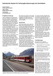
Project description Background Technology after reconstruction
Project description Background Technology after reconstruction
Project description Background Technology after reconstruction

You also want an ePaper? Increase the reach of your titles
YUMPU automatically turns print PDFs into web optimized ePapers that Google loves.
Refurbishment and Revision of two MOB Gm 4/4<br />
Pascal Tritten<br />
Railtec Systems GmbH<br />
Paul Baillif<br />
MOB / Golden Pass Services<br />
<strong>Project</strong> <strong>description</strong><br />
In the course of reconstructing the<br />
two diesel-electric shunting<br />
locomotives of type Gm 4/4 for MOB/<br />
Golden Pass Services the vehicle<br />
control systems were renewed. This<br />
involved complete refurbishment of<br />
the motor control system, generator<br />
controller, relay control, drive and<br />
braking control as well as the control<br />
systems for the auxiliary hydraulic<br />
plant. Railtec Systems GmbH<br />
performed these tasks in cooperation<br />
with the MOB workshop in Chernex.<br />
<strong>Background</strong><br />
MOB Golden Pass Services own two<br />
diesel-electric locomotives of type Gm<br />
4/4. These locomotives,<br />
manufactured in 1976 and 1982, were<br />
each equipped with a V12 Poyaud<br />
diesel engine rated at 485kW, which<br />
in turn powered a 3 phase<br />
synchronous generator supplied by<br />
Leroy-Somer. Two rectifiers supplied<br />
two direct current traction motors.<br />
The accelerator lever had a direct<br />
effect on the injection pump, altering<br />
the injection quantity and therefore<br />
indirectly the engine speed. A relay<br />
switch controlled the generator via a<br />
resistor switch, depending amongst<br />
other things on the engine- and<br />
vehicle speed.<br />
<strong>Technology</strong> <strong>after</strong><br />
<strong>reconstruction</strong><br />
Observation of normal operation<br />
showed that the locomotives are<br />
generally operated at low speeds. For<br />
this reason the decision was made to<br />
supply the current using two smaller<br />
The body of the Gm 4/4 2004 under construction, all electric components are still<br />
missing, the engines (at the back) are already installed. (Photo: Railtec Systems)<br />
'gensets' (one diesel engine with its<br />
coupled generator each) with their<br />
rectifiers in serial connection. This<br />
means that at low speeds only one<br />
diesel engine needs to be used, as<br />
the current passing through the serial<br />
coupling of the motors supplies<br />
sufficient traction force. Only when<br />
higher speeds or<br />
maximum traction<br />
force are required<br />
both diesel engines<br />
need to be used. The<br />
engines selected for<br />
use were new sixcylinder<br />
straight<br />
engines supplied by<br />
Scania with an<br />
electronically<br />
controlled unit injector<br />
system, each rated at<br />
316kW and powering<br />
a Leroy-Somer<br />
synchronous<br />
generator. Each of<br />
the diesel engines<br />
are connected to two<br />
hydraulic pumps to<br />
provide hydrostatic<br />
fans, traction motor fan and the<br />
vacuum pump for the vacuum brake.<br />
In each case, one of the pumps is<br />
used for the diesel engine's fan unit<br />
and the other for the traction motor<br />
fan and the vacuum pump for the<br />
brake.<br />
drive force for cooling<br />
3D-drawing of the engine's installation (Graphics: MOB)
Front view: On the right diesel engine 1 with flange-mounted hydraulic pump (Photo:<br />
MOB)<br />
Mechanical features<br />
It was decided to use the available<br />
space to accommodate the new<br />
drives without any significant<br />
alterations of the vehicle's frame. This<br />
was accomplished without raising<br />
problems of noise and heat<br />
generation. Owing to circumstances<br />
the two gensets had to be installed<br />
opposite to each other. Another<br />
requirement to be met was to allow,<br />
despite the cramped conditions, easy<br />
access to all components needing<br />
maintenance.<br />
Through the use of hydrostatic force<br />
for the operation of fans and vacuum<br />
pump, components could be freely<br />
positioned. This way, the driver's cab<br />
could be significantly lengthened.<br />
The entire drive chain – from the<br />
electric motor over the bogie to the<br />
transmission – could be used for the<br />
currently rated maximum load without<br />
Hydraulic contol, vehicle control,<br />
underneath the extension modules<br />
(Photo: MOB)<br />
any modifications.<br />
Control devices<br />
The vehicle control system consists of<br />
components selected from the<br />
Selectron MAS-T product range. A<br />
CPU 854 is used as master vehicle<br />
controller. The speed acquisition is<br />
performed by a module with RPM<br />
inputs. An additional CPU 723 serves<br />
as diesel engine coupler with two<br />
CAN interfaces. Finally, a separate I/<br />
O module with linked input and output<br />
extension units provides the required<br />
number of digital I/O. The hydraulic<br />
control system consists of two control<br />
devices supplied by Bosch-Rexroth.<br />
They are part of a package of<br />
hydraulic pumps and engines which<br />
includes configurable standard<br />
software for fan control.<br />
Drive-, brake- and serial/parallel<br />
contactors (Photo: MOB)<br />
Instead of the instrument panel<br />
supplied by the motor manufacturer, it<br />
was decided to provide the relevant<br />
motor information using a display. On<br />
one hand the panels would have<br />
taken up a considerable amount of<br />
space, on the other hand the control<br />
and monitoring of the individual diesel<br />
engines via CAN bus would not have<br />
been possible. Instead, the<br />
generation of digital and analogue<br />
signals would have become<br />
necessary. The display solution is less<br />
expensive than using two instrument<br />
panels and also provides<br />
considerably more flexibility in respect<br />
of operation and provided information.<br />
Also, data can be displayed which<br />
has nothing to do with the engines<br />
and which would otherwise have<br />
made one or more extra display<br />
devices or control lamps necessary.<br />
Finally, the conversion costs could<br />
also be reduced because the cabling<br />
is less complicated and only one<br />
installation recess for the display is<br />
needed.<br />
CAN Bus<br />
The CAN bus was divided into three<br />
sections, i.e. engine bus 1, engine<br />
bus 2 (each J1939) and the vehicle<br />
bus (CANopen). This division is<br />
necessary because it is not possible<br />
to modify the diesel engines' CAN bus<br />
node-ID, which made parallel<br />
operation of two engine control<br />
devices on one and the same bus<br />
impossible. The diesel engine coupler<br />
serves only to transmit data from<br />
diesel engine 2 to engine bus 2 and<br />
vice versa. Also, the possibility of<br />
connecting extension modules directly<br />
to the engine coupler has been<br />
implemented to interface digital input<br />
and output signals. Engine bus 1 is<br />
Motor power supply with rectifiers (Photo:<br />
MOB)
connected directly to the second CAN<br />
interface of the master vehicle<br />
controller. The protocol used for the<br />
two engine buses is the standard<br />
protocol used for serial<br />
communication within vehicle<br />
networks, written in SAE J1939.<br />
The hydraulic controls are also<br />
connected to the engine bus. The<br />
master vehicle controller, the<br />
computer for speed acquisition, the<br />
engine coupler, additional I/O nodes<br />
and the display are connected to the<br />
vehicle bus.<br />
Control<br />
In exceptional cases, e.g. when a<br />
genset or a traction motor is defect,<br />
the driver can manually select the<br />
diesel engine to be used. Then only<br />
one genset is in operation, supplying<br />
power to one of the two traction<br />
motors.<br />
In automatic operation one or the<br />
other of the engines is in operation<br />
and the traction motors are coupled in<br />
series.<br />
The automatic diesel engine selection<br />
is managed by the master vehicle<br />
controller. When both engines are<br />
cold, the engine with fewer operating<br />
hours is selected. If one of the<br />
Busaufteilung (Grafik: Railtec Systems)<br />
engines has already warmed up, then<br />
this one is used on every subsequent<br />
start-up so as to reduce the number<br />
of cold starts and therefore help<br />
protect both the engines and the<br />
environment.<br />
In dual engine mode both gensets are<br />
in operation and the rectifiers and<br />
2 March 2008: Comissioning on the line Blonay-Chamby (Photo: Railtec Systems)<br />
traction motors are switched in series.<br />
This mode is required to attain<br />
maximum speed.<br />
In both operating modes the master<br />
vehicle controller calculates the<br />
engine activity according to the<br />
position of the accelerator lever and<br />
the diesel engine's rated RPM. The<br />
necessary voltage (0..40V DC) for<br />
excitation of the synchronous<br />
generators is provided by an<br />
excitation device supplied by Syko<br />
Power. The excitation device is<br />
powered through the vehicle's 24V<br />
system. The desired value is set via<br />
an analogue voltage signal 0..5V.<br />
The diesel engine's speed is<br />
optimised for fuel economy. The<br />
master vehicle controller monitors and<br />
limits motor voltages and currents as<br />
well as cooling water, generator,<br />
rectifier and traction motor<br />
temperatures. If the limiting values<br />
are exceeded the speed and<br />
generator excitation are automatically<br />
adjusted or the respective drive<br />
component is switched off. The<br />
master vehicle controller also controls<br />
the slip and overspeed protection<br />
systems (only for the electric brake).<br />
All relays are switched by the master<br />
vehicle controller (traction and braking<br />
relay, direction of travel relay,<br />
switching from parallel to series<br />
operation, shunt relay). All relays are<br />
equipped with auxiliary contacts<br />
which allow the relay state to be<br />
monitored. If the return signal does<br />
not match the command given, then<br />
either the activation is cancelled or<br />
only an error message is issued.<br />
The master vehicle controller also<br />
controls the driver's safety device<br />
(dead man's switch), the sand<br />
dispenser, battery levels and other<br />
functions.<br />
The software for the two hydraulic<br />
controls is an adapted version of the<br />
automatic AFC20 fan control program<br />
supplied by Bosch-Rexroth.<br />
The option to provide for an<br />
emergency power supply (using a<br />
genset to generate 3x400V 50Hz, for<br />
instance for electrical equipment in<br />
the field) was not implemented due to<br />
cost and absence of urgent necessity.
Test run on 15 March 2008 in Sonzier (Photo: Railtec Systems)<br />
However, it can be implemented<br />
subsequently without difficulty.<br />
Error recognition and<br />
diagnosis<br />
All the relay states are registered and<br />
compared with the commands issued<br />
for their activation. If a discrepancy is<br />
found, an error message is issued<br />
and an appropriate action triggered.<br />
Diesel engine malfunctions are<br />
detected and stored by the respective<br />
engine control devices. For the<br />
purposes of reading these error<br />
entries, part of the diagnostic protocol<br />
UDS on CAN (as per ISO 15765) was<br />
implemented. This protocol is<br />
increasingly displacing the KWP2000<br />
(Key Word Protocol 2000) protocol<br />
widely used in road vehicles. This<br />
means that the data from<br />
neighbouring components can be<br />
queried corresponding to the point in<br />
time when the error has occurred.<br />
Also, it is possible to delete individual<br />
errors or the whole error memory. It is<br />
no longer necessary to buy an<br />
expensive proprietary test and<br />
diagnostic device.<br />
Display<br />
The display is PC based and supplied<br />
by Pixy AG from Aargau, Switzerland.<br />
As operating system a Linux kernel is<br />
installed. All texts and labels are<br />
provided in German and French.<br />
The items displayed are modelled as<br />
conventional instruments. Process<br />
values displayed in this fashion can<br />
generally be more easily and quickly<br />
interpreted than numeric displays,<br />
and the interface can be configured<br />
more clearly.<br />
The display is also used for the<br />
storage and display of vehicle-,<br />
motor- or engine malfunctions.<br />
Malfunctions are stored in non-volatile<br />
memory together with the relevant<br />
data from neighbouring components.<br />
This information can be used for<br />
subsequent localisation and<br />
correction of faults.<br />
Summary<br />
The conversion has provided MOB<br />
with diesel locomotives equipped with<br />
most modern technology. During the<br />
conversion, environmental aspects<br />
such as fuel consumption, exhaust<br />
and noise emissions were treated<br />
with high priority. The two Gm 4/4 can<br />
now continue to fulfil their tasks for<br />
another 20 years.<br />
16 March 2008: Gm 4/4 2004 in Les<br />
Cases (Photo: Railtec Systems)