A Spoked Wheel Structure for the World's largest - IABSE E - Learning
A Spoked Wheel Structure for the World's largest - IABSE E - Learning
A Spoked Wheel Structure for the World's largest - IABSE E - Learning

You also want an ePaper? Increase the reach of your titles
YUMPU automatically turns print PDFs into web optimized ePapers that Google loves.
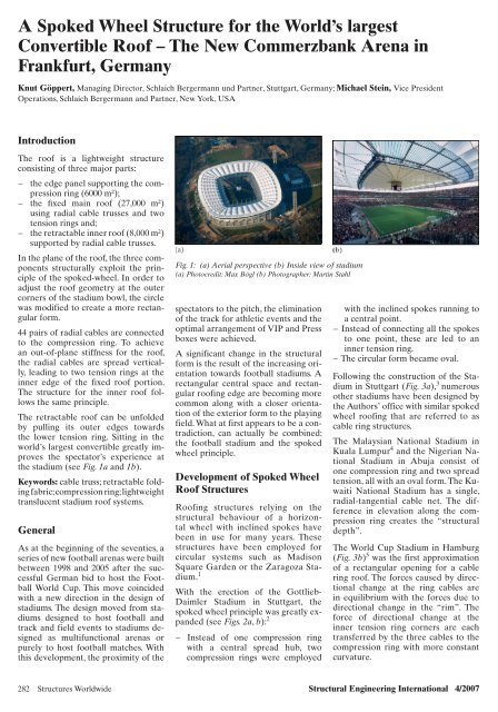
A <strong>Spoked</strong> <strong>Wheel</strong> <strong>Structure</strong> <strong>for</strong> <strong>the</strong> World’s <strong>largest</strong><br />
Convertible Roof – The New Commerzbank Arena in<br />
Frankfurt, Germany<br />
Knut Göppert, Managing Director, Schlaich Bergermann und Partner, Stuttgart, Germany; Michael Stein, Vice President<br />
Operations, Schlaich Bergermann and Partner, New York, USA<br />
Introduction<br />
The roof is a lightweight structure<br />
consisting of three major parts:<br />
− <strong>the</strong> edge panel supporting <strong>the</strong> compression<br />
ring (6000 m²);<br />
− <strong>the</strong> fi xed main roof (27,000 m²)<br />
using radial cable trusses and two<br />
tension rings and;<br />
− <strong>the</strong> retractable inner roof (8,000 m²)<br />
supported by radial cable trusses.<br />
In <strong>the</strong> plane of <strong>the</strong> roof, <strong>the</strong> three components<br />
structurally exploit <strong>the</strong> principle<br />
of <strong>the</strong> spoked-wheel. In order to<br />
adjust <strong>the</strong> roof geometry at <strong>the</strong> outer<br />
corners of <strong>the</strong> stadium bowl, <strong>the</strong> circle<br />
was modified to create a more rectangular<br />
<strong>for</strong>m.<br />
44 pairs of radial cables are connected<br />
to <strong>the</strong> compression ring. To achieve<br />
an out-of-plane stiffness <strong>for</strong> <strong>the</strong> roof,<br />
<strong>the</strong> radial cables are spread vertically,<br />
leading to two tension rings at <strong>the</strong><br />
inner edge of <strong>the</strong> fixed roof portion.<br />
The structure <strong>for</strong> <strong>the</strong> inner roof follows<br />
<strong>the</strong> same principle.<br />
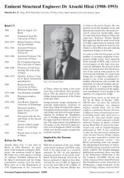
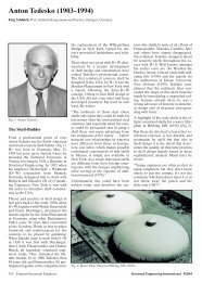
The retractable roof can be unfolded<br />
by pulling its outer edges towards<br />
<strong>the</strong> lower tension ring. Sitting in <strong>the</strong><br />
world’s <strong>largest</strong> convertible greatly improves<br />
<strong>the</strong> spectator’s experience at<br />
<strong>the</strong> stadium (see Fig. 1a and 1b).<br />
Keywords: cable truss; retractable folding<br />
fabric; compression ring; lightweight<br />
translucent stadium roof systems.<br />
General<br />
As at <strong>the</strong> beginning of <strong>the</strong> seventies, a<br />
series of new football arenas were built<br />
between 1998 and 2005 after <strong>the</strong> successful<br />
German bid to host <strong>the</strong> Football<br />
World Cup. This move coincided<br />
with a new direction in <strong>the</strong> design of<br />
stadiums. The design moved from stadiums<br />
designed to host football and<br />
track and field events to stadiums designed<br />
as multifunctional arenas or<br />
purely to host football matches. With<br />
this development, <strong>the</strong> proximity of <strong>the</strong><br />
Fig. 1: (a) Aerial perspective (b) Inside view of stadium<br />
(a) Photocredit: Max Bögl (b) Photographer: Martin Stahl<br />
spectators to <strong>the</strong> pitch, <strong>the</strong> elimination<br />
of <strong>the</strong> track <strong>for</strong> athletic events and <strong>the</strong><br />
optimal arrangement of VIP and Press<br />
boxes were achieved.<br />
A significant change in <strong>the</strong> structural<br />
<strong>for</strong>m is <strong>the</strong> result of <strong>the</strong> increasing orientation<br />
towards football stadiums. A<br />
rectangular central space and rectangular<br />
roofing edge are becoming more<br />
common along with a closer orientation<br />
of <strong>the</strong> exterior <strong>for</strong>m to <strong>the</strong> playing<br />
field. What at first appears to be a contradiction,<br />
can actually be combined:<br />
<strong>the</strong> football stadium and <strong>the</strong> spoked<br />
wheel principle.<br />
Development of <strong>Spoked</strong> <strong>Wheel</strong><br />
Roof <strong>Structure</strong>s<br />
Roofing structures relying on <strong>the</strong><br />
structural behaviour of a horizontal<br />
wheel with inclined spokes have<br />
been in use <strong>for</strong> many years. These<br />
structures have been employed <strong>for</strong><br />
circular systems such as Madison<br />
Square Garden or <strong>the</strong> Zaragoza Stadium.<br />
1<br />
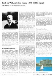
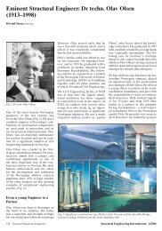
With <strong>the</strong> erection of <strong>the</strong> Gottlieb-<br />
Daimler Stadium in Stuttgart, <strong>the</strong><br />
spoked wheel principle was greatly expanded<br />
(see Figs. 2a, b): 2<br />
− Instead of one compression ring<br />
with a central spread hub, two<br />
compression rings were employed<br />
with <strong>the</strong> inclined spokes running to<br />
a central point.<br />
− Instead of connecting all <strong>the</strong> spokes<br />
to one point, <strong>the</strong>se are led to an<br />
inner tension ring.<br />
− The circular <strong>for</strong>m became oval.<br />
Following <strong>the</strong> construction of <strong>the</strong> Stadium<br />
in Stuttgart (Fig. 3a), 3 numerous<br />
o<strong>the</strong>r stadiums have been designed by<br />
<strong>the</strong> Authors’ office with similar spoked<br />
wheel roofing that are referred to as<br />
cable ring structures.<br />
The Malaysian National Stadium in<br />
Kuala Lumpur 4 and <strong>the</strong> Nigerian National<br />
Stadium in Abuja consist of<br />
one compression ring and two spread<br />
tension, all with an oval <strong>for</strong>m. The Kuwaiti<br />
National Stadium has a single,<br />
radial-tangential cable net. The difference<br />
in elevation along <strong>the</strong> compression<br />
ring creates <strong>the</strong> “structural<br />
depth”.<br />
The World Cup Stadium in Hamburg<br />
(Fig. 3b) 5 was <strong>the</strong> first approximation<br />
of a rectangular opening <strong>for</strong> a cable<br />
ring roof. The <strong>for</strong>ces caused by directional<br />
change at <strong>the</strong> ring cables are<br />
in equilibrium with <strong>the</strong> <strong>for</strong>ces due to<br />
directional change in <strong>the</strong> “rim”. The<br />
<strong>for</strong>ce of directional change at <strong>the</strong><br />
inner tension ring corners are each<br />
transferred by <strong>the</strong> three cables to <strong>the</strong><br />
compression ring with more constant<br />
curvature.<br />
282 <strong>Structure</strong>s Worldwide Structural Engineering International 4/2007
(a) (b)<br />
Fig. 2: Viable spoked wheel arrangements (Photocredit: sbp)<br />
Fig. 3: (a) Gottlieb Daimler stadium (b) World Cup Stadium Hamburg<br />
(a) Photocredit: Manfred Storck (b) Photographer: euroluftbild<br />
In order to eliminate any important bending<br />
stresses in <strong>the</strong> rim under self weight,<br />
<strong>the</strong> following conditions must be met:<br />
− The self weight of <strong>the</strong> light structure<br />
has a negligible impact on <strong>the</strong> <strong>for</strong>ces<br />
in <strong>the</strong> supporting elements.<br />
− The <strong>for</strong>m of <strong>the</strong> tension and compression<br />
chords are funicular with<br />
respect to one ano<strong>the</strong>r.<br />
The possibilities opened up by this<br />
construction principle can be fur<strong>the</strong>r<br />
developed and combined. Two current<br />
examples of this fur<strong>the</strong>r development,<br />
in Durban, South Africa and Delhi,<br />
India, are currently being designed and<br />
executed in close collaboration with<br />
<strong>the</strong> architects.<br />
The Stadium Roof <strong>Structure</strong><br />
The compression ring along <strong>the</strong> circumference<br />
of <strong>the</strong> stadium bowl <strong>for</strong>ms<br />
<strong>the</strong> rim of <strong>the</strong> cable ring system. The<br />
central hub is replaced by a cable ring<br />
in which <strong>the</strong> tension <strong>for</strong>ces are carefully<br />
balanced with <strong>the</strong> <strong>for</strong>ces of <strong>the</strong><br />
compression ring. Radial cable girders<br />
make up <strong>the</strong> spokes and connect <strong>the</strong><br />
rings.<br />
In elevation, several combinations<br />
of compression ring(s) and tension<br />
ring(s) have been explored. The results<br />
of detailed analysis led to a system<br />
having one compression ring above<br />
<strong>the</strong> outer edge of <strong>the</strong> bowl with radial<br />
cables spreading out towards <strong>the</strong><br />
inside of <strong>the</strong> stadium and ending in<br />
two parallel tension rings running on<br />
top of each o<strong>the</strong>r. From <strong>the</strong>re <strong>the</strong> radial<br />
cables of <strong>the</strong> inner roof start and<br />
meet at <strong>the</strong> centre of <strong>the</strong> stadium at –<br />
<strong>the</strong>oretically – one point. The vertical<br />
components of <strong>the</strong> upper and lower<br />
tension ring are balanced by means of<br />
vertical struts.<br />
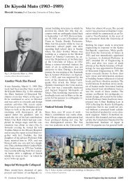
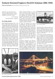
The complete roof structure is supported<br />
by slender vertical columns<br />
of 8,5 m height in each axis. The roof<br />
<strong>the</strong>re<strong>for</strong>e appears to be floating almost<br />
weightlessly above <strong>the</strong> stands<br />
(see Fig. 4a, b).<br />
The roof cladding consists of a combination<br />
of four different materials:<br />
– The metal cladding at <strong>the</strong> outer<br />
edge hides <strong>the</strong> slightly different<br />
curvature of <strong>the</strong> stadium bowl and<br />
compression ring. More curvature is<br />
necessary <strong>for</strong> <strong>the</strong> compression ring<br />
to create a viable structural system<br />
with moderate <strong>for</strong>ces. The edges<br />
of <strong>the</strong> metal cladding are arranged<br />
parallel to <strong>the</strong> bowl’s edges.<br />
– The material of <strong>the</strong> fi xed roof is a<br />
PTFE (Polytetrafl uoroethylene) coated<br />
glass fabric, which is located on<br />
<strong>the</strong> lower cable level reducing <strong>the</strong><br />
vertical distance to <strong>the</strong> stands.<br />
– To improve <strong>the</strong> interior lighting<br />
situation, a 15-m wide area of polycarbonate<br />
sheets is arranged parallel<br />
to <strong>the</strong> tension ring. These sheets<br />
have a high level of translucency<br />
(85%) whereas <strong>the</strong> roof achieves<br />
15%. The polycarbonate also closes<br />
<strong>the</strong> catenary-shaped gap between<br />
<strong>the</strong> inner and outer fabrics.<br />
– The material of <strong>the</strong> retractable roof<br />
is PVC (polymer of vinyl chloride)<br />
coated polyester with additional<br />
PVDF (Polyvinylidene Flouride)<br />
coating on <strong>the</strong> upper side. It is<br />
situated at <strong>the</strong> lower cable level of<br />
<strong>the</strong> inner roof.<br />
In standard spoked wheel structures,<br />
ring geometries and ring <strong>for</strong>ces are<br />
strongly dependent on each o<strong>the</strong>r and<br />
cannot be chosen freely. The inner<br />
roof of <strong>the</strong> Frankfurt Stadium helps to<br />
overcome this design limitation.<br />
The structure of <strong>the</strong> inner roof follows<br />
<strong>the</strong> same principles as <strong>the</strong> outer roof,<br />
resulting in two interlocked spoke<br />
wheels with one outer compression<br />
ring, two tension rings and <strong>the</strong> central<br />
hub. This combination allows a<br />
choice of <strong>the</strong> geometry of <strong>the</strong> tension<br />
ring freely as <strong>the</strong> balancing <strong>for</strong>ces<br />
<strong>for</strong> <strong>the</strong> compression ring could be assigned<br />
to <strong>the</strong> tension ring or <strong>the</strong> hub<br />
Structural Engineering International 4/2007 <strong>Structure</strong>s Worldwide 283
200,15<br />
(a)<br />
(b)<br />
60,72 78,70 60,72<br />
8,90<br />
Fig. 4: (a) Plan view (b) Section of stadium structure, Units: m (a+b Photocredit: sbp)<br />
respectively. Not only <strong>the</strong> horizontal<br />
position could be adjusted but also<br />
<strong>the</strong> vertical shape of <strong>the</strong> roof, leading<br />
to several architectural options<br />
as well as <strong>the</strong> possibility of arranging<br />
<strong>the</strong> drainage in <strong>the</strong> corner areas of<br />
<strong>the</strong> roof.<br />
Structural Analysis<br />
All primary structural members, i.e. columns,<br />
compression ring, radial cables<br />
and ring cables of <strong>the</strong> inner and outer<br />
roof and <strong>the</strong> flying struts, were simulated<br />
in one computer model. Using a<br />
high end software package, this model<br />
was analysed using geometrically non-<br />
238,55<br />
62,35 113,85 62,35<br />
Centrol node<br />
Radial cables<br />
Inner roof<br />
Membrane<br />
fixed roof<br />
Radial cables<br />
Outer roof<br />
linear solvers as recommended <strong>for</strong> all<br />
major tensile structures.<br />
The columns and <strong>the</strong> compression ring<br />
were modeled as beam elements, <strong>the</strong><br />
flying masts as strut elements and all<br />
cables including <strong>the</strong> bracing diagonals<br />
as cable elements. The covering as secondary<br />
element was not considered in<br />
<strong>the</strong> global model.<br />
The most important step at <strong>the</strong> beginning<br />
of <strong>the</strong> analysis of a tensile structure<br />
is <strong>the</strong> <strong>for</strong>m-finding in which <strong>the</strong><br />
geometry and <strong>for</strong>ces of <strong>the</strong> primary<br />
elements are coordinated in <strong>the</strong> most<br />
efficient way under a chosen loading<br />
condition. The results of this iterative<br />
Compression Ring<br />
1500 x 1000<br />
Inner roof:<br />
PVC/PES A = 8500 m 2<br />
Outer roof:<br />
PTFE/GLASFASER A = 22000 m<br />
Polycarbonate<br />
A = 6000 m 2<br />
Metal cladding<br />
A = 6200 m 2<br />
240,50<br />
58,90 61,34 61,34 58,90<br />
8,90 Fixed roof Inner roof Inner roof Fixed roof<br />
8,90<br />
Upper ring cable<br />
4xVVS<br />
Flying mast<br />
Lower ring cable<br />
6xVVS<br />
Central node<br />
Videocube<br />
Upper ring cable<br />
Hanger cable<br />
Membran - fixed roof<br />
Lower radial cable<br />
Connection girder<br />
Compression ring<br />
+36,01<br />
Roof column<br />
∅355,6<br />
process, i.e. geometry and <strong>for</strong>ces, constitutes<br />
<strong>the</strong> basis <strong>for</strong> all <strong>the</strong> following<br />
calculations (see Fig. 5).<br />
DIN German Standard was used to<br />
define <strong>the</strong> standard loading provisions.<br />
The wind loads on <strong>the</strong> roof were<br />
derived in a wind tunnel test considering<br />
local topography and urban environment.<br />
The retractable roof was<br />
designed to withstand summer loading<br />
conditions only as <strong>the</strong> roof should only<br />
be deployed between May and October<br />
of each year. However, as extreme<br />
summer conditions like hail storms<br />
had to be considered in <strong>the</strong> design, <strong>the</strong><br />
load could only be reduced to 65% of<br />
<strong>the</strong> full snow load. During <strong>the</strong> moving<br />
284 <strong>Structure</strong>s Worldwide Structural Engineering International 4/2007<br />
+27,51<br />
±0,00
Fig. 5: Retractable roof area (Photocredit: sbp)<br />
operation itself <strong>the</strong> loads due to wind<br />
or rain were restricted to a practical<br />
minimum. This requires responsible operational<br />
management to close <strong>the</strong> roof<br />
<strong>for</strong> one event and includes contacting<br />
<strong>the</strong> local meteorological institutions <strong>for</strong><br />
specific wea<strong>the</strong>r <strong>for</strong>ecasts. As <strong>the</strong> moving<br />
operations take 15 minutes, <strong>the</strong>se<br />
provisions were found to be practical.<br />
One of <strong>the</strong> most challenging parts of<br />
<strong>the</strong> structural analysis is <strong>the</strong> stability<br />
check <strong>for</strong> <strong>the</strong> compression ring, as standards<br />
or o<strong>the</strong>r provisions are hardly<br />
applicable. The well-established process,<br />
which was used <strong>for</strong> <strong>the</strong> compression<br />
ring here, is to calculate maximum<br />
stresses in <strong>the</strong> ring under factored loading<br />
including imperfections. The imperfections<br />
should be adopted by using <strong>the</strong><br />
scaled deflections under <strong>the</strong> first eigenfrequency<br />
of <strong>the</strong> system. Special attention<br />
is required to scale <strong>the</strong> deflections<br />
carefully and coordinate <strong>the</strong>m with <strong>the</strong><br />
specified tolerances. As a final step, a<br />
standard buckling check was carried<br />
out <strong>for</strong> each compression ring element.<br />
Several sub-models were created to account<br />
<strong>for</strong> secondary structural systems<br />
such as <strong>the</strong> structure of <strong>the</strong> inner and<br />
outer roof, <strong>the</strong> catwalk including <strong>the</strong><br />
support structure <strong>for</strong> <strong>the</strong> polycarbonate<br />
cover and <strong>the</strong> video cube.<br />
Special attention was given to <strong>the</strong> central<br />
hub, where a total of 96 cables<br />
are connected in <strong>the</strong> minimum possible<br />
area. The maximum total <strong>for</strong>ce<br />
which was introduced into <strong>the</strong> hub<br />
was 30,000 kN from both main axes of<br />
<strong>the</strong> stadium. One quarter of <strong>the</strong> node<br />
was reproduced with a finite element<br />
model using a Software and analysed,<br />
considering <strong>the</strong> main cable <strong>for</strong>ces from<br />
<strong>the</strong> global model. Special welding and<br />
erection procedures were developed<br />
to guarantee <strong>the</strong> safe transmission of<br />
<strong>the</strong> predicted <strong>for</strong>ces.<br />
Retractable Roof<br />
Upper/Lower<br />
Radial cable inner roof<br />
Hanger<br />
Upper/Lower<br />
Radial cable fixed roof<br />
Connection girder<br />
Upper ring cable<br />
Column<br />
Wind bracing<br />
Compression ring 1500x1000<br />
Lower ring cable<br />
Flying mast<br />
Central node<br />
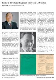
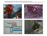
The retractable roof can be unfolded<br />
along <strong>the</strong> inner radial cables. The nondeployed<br />
position of <strong>the</strong> roof is folded<br />
up in <strong>the</strong> central video cube of <strong>the</strong> stadium.<br />
The video cube and its roof have<br />
to be designed properly to withstand<br />
all possible loading conditions during<br />
<strong>the</strong> entire year and to protect <strong>the</strong><br />
membrane package from severe environmental<br />
conditions (Fig. 6).<br />
The fabric is connected by means of<br />
polyester straps to gliding steel trolleys<br />
in distances varying from approximately<br />
6–9 m. The steel trolleys are<br />
hooked to <strong>the</strong> primary steel cables of<br />
<strong>the</strong> inner roof. These are double cables<br />
spaced 250 mm apart to provide stable<br />
gliding conditions. To avoid any direct<br />
gliding of steel on steel, <strong>the</strong> trolleys are<br />
equipped with hard-wearing blocks of<br />
syn<strong>the</strong>tic material at <strong>the</strong> contact zone<br />
to <strong>the</strong> steel cables.<br />
At <strong>the</strong> outer edges of <strong>the</strong> fabric, <strong>the</strong><br />
driving trolley is connected to an endless<br />
steel cable which is guided along<br />
each radial cable and looped around<br />
a winch located near <strong>the</strong> tension ring.<br />
Using a motor-operated winch, <strong>the</strong><br />
cable can be moved, and so can <strong>the</strong><br />
driving trolley. When deploying <strong>the</strong><br />
roof, <strong>the</strong> driving trolley pulls all gliding<br />
trolleys, as <strong>the</strong>y are connected via<br />
<strong>the</strong> fabric. Folding <strong>the</strong> roof toge<strong>the</strong>r<br />
<strong>the</strong> driving trolley pushes <strong>the</strong> o<strong>the</strong>r<br />
trolleys by direct contact (see Figs. 7<br />
a,b).<br />
The motor-operated winch allows fast<br />
traveling, but cannot be used to introduce<br />
<strong>the</strong> prestress into <strong>the</strong> fabric,<br />
required to provide a stable load carrying<br />
system. For this reason <strong>the</strong> driving<br />
trolley is mechanically locked to a<br />
stressing device at <strong>the</strong> very end of <strong>the</strong><br />
deploying process. The stressing device<br />
Fig. 6: Retractable roof operation<br />
(Photographer: Heiner Leiska)<br />
consists of a pair of hydraulic cylinders.<br />
These cylinders introduce high local<br />
<strong>for</strong>ces at <strong>the</strong> outer edge to stress <strong>the</strong><br />
entire fabric properly and to withstand<br />
<strong>the</strong> concentrated local <strong>for</strong>ces under<br />
loading conditions.<br />
The travelling process requires coordination<br />
between <strong>the</strong> 34 inner roof axes<br />
to avoid uncontrollable side-effects due<br />
to uneven driving velocities or local<br />
interferences. The mechanical devices<br />
and <strong>the</strong> software had to pass extensive<br />
long term tests at <strong>the</strong> fabrication site<br />
Structural Engineering International 4/2007 <strong>Structure</strong>s Worldwide 285
(a)<br />
(b)<br />
Fig. 7 (a, b): Mechanical devices (Trolleys)<br />
of retractable roof (a+b Photocredit: sbp)<br />
be<strong>for</strong>e <strong>the</strong> system was approved by <strong>the</strong><br />
authorities and <strong>the</strong> engineers.<br />
The required volume of <strong>the</strong> video cube<br />
to store <strong>the</strong> folded package of <strong>the</strong> inner<br />
fabric was investigated in three different<br />
ways:<br />
− The physical model of <strong>the</strong> inner roof,<br />
to get a deeper understanding of<br />
<strong>the</strong> complex geometrical processes<br />
during folding of <strong>the</strong> membrane<br />
(Fig. 8a).<br />
As <strong>for</strong> most scaled models, it is necessary<br />
to find a material with <strong>the</strong> correct<br />
weight and <strong>the</strong> correct bending stiffness<br />
as <strong>the</strong> folding is strongly dependent<br />
on both parameters. Ultimately,<br />
special fabrics from <strong>the</strong> apparel industry<br />
were used to obtain useful results.<br />
− Computer model using software of<br />
<strong>the</strong> automobile industry (airbag<br />
folding).<br />
To gain practical results with computer<br />
models, very detailed finite element<br />
systems are required. The finite<br />
elements must be defined as contact<br />
elements, simulating <strong>the</strong> folding process,<br />
not a standard software in <strong>the</strong><br />
(a)<br />
(b)<br />
Fig. 8 (a, b): Scaled model and 1:1 Mock-up (a+b Photocredit: sbp)<br />
construction industry. To reduce <strong>the</strong><br />
necessary calculation time, only half a<br />
bay was modeled and calculated first.<br />
This calculation proved <strong>the</strong> results of<br />
<strong>the</strong> scaled physical model, so bigger<br />
computer models were unnecessary.<br />
− Mock-up of one eighth of <strong>the</strong> roof<br />
checking <strong>the</strong> folded condition<br />
(Fig. 8b).<br />
The final step was <strong>the</strong> 1:1 model with<br />
part of <strong>the</strong> actual roof itself at <strong>the</strong><br />
fabrication site. This final check has<br />
proved that <strong>the</strong> chosen volume of <strong>the</strong><br />
video cube could be considered as sufficient.<br />
Some uncertainty remained as<br />
<strong>the</strong> influences of temperature and <strong>the</strong><br />
repeated folding and unfolding on <strong>the</strong><br />
volume of <strong>the</strong> fabric package could not<br />
be estimated exactly. Now, all testing<br />
operations have certified <strong>the</strong> design<br />
volume as adequate.<br />
Fabrication and Erection<br />
As <strong>the</strong> complete renovation of <strong>the</strong> stadium<br />
was per<strong>for</strong>med while <strong>the</strong> stadium<br />
was in service, well-coordinated erection<br />
procedures, not only <strong>for</strong> <strong>the</strong> stands<br />
but also <strong>for</strong> <strong>the</strong> roof, were crucial <strong>for</strong><br />
<strong>the</strong> successful completion of <strong>the</strong> project.<br />
Increasing <strong>the</strong> amount of prefabrication<br />
and reducing <strong>the</strong> required<br />
time at <strong>the</strong> site during erection, proved<br />
286 <strong>Structure</strong>s Worldwide Structural Engineering International 4/2007
to be <strong>the</strong> right approach to <strong>the</strong> coordination<br />
problem. This led to unique<br />
fabrication and erection methods.<br />
To meet <strong>the</strong> assumptions of <strong>the</strong> structural<br />
analysis, <strong>the</strong> compression ring has<br />
to be fabricated following strict tolerance<br />
requirements both in <strong>the</strong> length<br />
of each element and angular deviation<br />
of <strong>the</strong> end plates. One effective method,<br />
also applied in previous stadium<br />
projects, is to sequentially machine <strong>the</strong><br />
end plates of each compression ring<br />
element and to per<strong>for</strong>m immediate<br />
trial assemblies at <strong>the</strong> fabrication site.<br />
Intolerable deviation at one element<br />
can be settled by correcting adjacent<br />
elements. This approach, which might<br />
sound complex and costly with respect<br />
to <strong>the</strong> fabrication, pays off during erection.<br />
The compression ring elements<br />
can be quickly erected one after <strong>the</strong><br />
o<strong>the</strong>r and fixed toge<strong>the</strong>r, after <strong>the</strong> columns<br />
and linking girders are installed<br />
and temporarily fixed. The placement<br />
is very precise and major surveying<br />
during erection can be avoided by <strong>the</strong><br />
attention during fabrication, saving immense<br />
time and money at <strong>the</strong> site.<br />
The complete compression ring must be<br />
finished to start with <strong>the</strong> installation of<br />
<strong>the</strong> cable structure. The cables are completely<br />
pre-fabricated, cut to extremely<br />
tight tolerances, connected with <strong>the</strong> end<br />
sockets and delivered at <strong>the</strong> site.<br />
In <strong>the</strong> next step, <strong>the</strong> cables are laid out<br />
on <strong>the</strong> stands and <strong>the</strong> field. All cables<br />
are connected to each o<strong>the</strong>r with cast<br />
steel clamps and ring connectors, producing<br />
one single cable net. The radial<br />
cables are connected by means of temporary<br />
strands to lifting jacks fixed to<br />
<strong>the</strong> compression ring. By pulling <strong>the</strong>se<br />
temporary strands, <strong>the</strong> complete cable<br />
net can be lifted off <strong>the</strong> floor towards<br />
its final position (Fig. 9a).<br />
As all 44 axes are pulled at <strong>the</strong> same<br />
time <strong>the</strong> jacks have to be carefully coordinated<br />
from a control panel, checking<br />
geometry and <strong>the</strong> corresponding <strong>for</strong>ces.<br />
After a certain height is reached, <strong>the</strong><br />
flying masts are installed and <strong>the</strong> lifting<br />
of <strong>the</strong> cable net completed (Fig. 9b).<br />
During <strong>the</strong> complete lifting process <strong>the</strong><br />
cable net represents a stable structural<br />
system. After <strong>the</strong> cable net is installed,<br />
Fig. 9: (a) Central node be<strong>for</strong>e lift-off (b)<br />
Radial cables during erection (a + b Photocredit:<br />
sbp)<br />
<strong>the</strong> arches and <strong>the</strong> fabric are erected<br />
bay by bay, following structural and<br />
operational requirements. The catwalk,<br />
including <strong>the</strong> polycarbonate roof,<br />
is erected in parallel. In <strong>the</strong> middle of<br />
<strong>the</strong> roof <strong>the</strong> steel skeleton of <strong>the</strong> video<br />
cube is connected to <strong>the</strong> central hub of<br />
<strong>the</strong> cable structure and all mechanical<br />
devices are installed and tested.<br />
Finally, <strong>the</strong> inner roof is installed. It<br />
was delivered in a single piece of approximately<br />
8,500 m 2 . After waiting<br />
<strong>for</strong> low winds and reconfirming <strong>the</strong><br />
wea<strong>the</strong>r conditions, <strong>the</strong> raising of <strong>the</strong><br />
entire inner roof is begun by connecting<br />
<strong>the</strong> polyester straps sequentially<br />
to <strong>the</strong> trolleys located near <strong>the</strong> central<br />
hub. The procedure is finished after an<br />
uninterrupted construction period of<br />
approximately two days.<br />
Conclusion<br />
The roof of <strong>the</strong> Commerzbank Arena<br />
was a technical challenge requiring<br />
<strong>the</strong> innovative solutions of all project<br />
participants. Described as “<strong>the</strong> world’s<br />
biggest convertible” it has proved itself<br />
over <strong>the</strong> last two years in a series of<br />
sports and o<strong>the</strong>r events including <strong>the</strong><br />
football World Cup in 2006.<br />
The roof demonstrates that lightweight<br />
designs with modern materials<br />
are definitely attractive alternatives to<br />
standard structures. The final layout of<br />
<strong>the</strong> structural members proved again<br />
<strong>the</strong> tremendous adaptability of cable<br />
supported roof structures.<br />
References<br />
[1] Göppert K, Schlaich J. The essence of Lightweight<br />
<strong>Structure</strong>s. Brussels University Press,<br />
2002.<br />
[2] Bergermann R, Göppert K. Das Speichenrad–<br />
Ein Konstruktionsprinzip für weitgespannte<br />
Dachkonstruktionen. Stahlbau 2000; 69, Heft 8.<br />
[3] Schlaich J., Bergermann R. Light <strong>Structure</strong>s.<br />
Prestel: München, 2003.<br />
[4] Schlaich J, Bergermann R, Göppert K. Textile<br />
Überdachungen für die Sportstätten der Commonwealth<br />
Games 1998 in Kuala Lumpur/Malaysia.<br />
Bauen mit Textilien 1999; 2.<br />
[5] Koch K-M, Habermann KJ. Membrane <strong>Structure</strong>s.<br />
Prestel Verlag: München, 2004.<br />
SEI Data Block<br />
Owner/Client:<br />
Waldstadion Frankfurt an Main,<br />
Gesellschaft für Projektentwicklungen<br />
mbH<br />
Main Contractor:<br />
Max Bögl Bauunternehmung GmbH<br />
& Co. KG, Neumarkt<br />
Architect:<br />
von Gerkan, Marg und Partner, Berlin<br />
Structural engineers of roof structure:<br />
Schlaich Bergermann und Partner,<br />
Stuttgart Knut Göppert, Michael Stein,<br />
Markus Balz, Bernd Ruhnke,<br />
Uli Dillmann<br />
Structural engineers of r/c structure:<br />
Krebs und Kiefer, Karlsruhe<br />
Total Cost (USD millions):<br />
200 USD Mill. <strong>for</strong> <strong>the</strong> total project / 30<br />
USD Mill. <strong>for</strong> <strong>the</strong> roof structure<br />
Service Date: August, 2005<br />
Structural Engineering International 4/2007 <strong>Structure</strong>s Worldwide 287