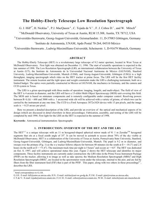
The Hobby-Eberly Telescope Low Resolution Spectrograph
The Hobby-Eberly Telescope Low Resolution Spectrograph
The Hobby-Eberly Telescope Low Resolution Spectrograph

You also want an ePaper? Increase the reach of your titles
YUMPU automatically turns print PDFs into web optimized ePapers that Google loves.
<strong>The</strong> <strong>Hobby</strong>-<strong>Eberly</strong> <strong>Telescope</strong> <strong>Low</strong> <strong>Resolution</strong> <strong>Spectrograph</strong><br />
G. J. Hill a* , H. Nicklas b , P.J. MacQueen a , C. Tejada de V. c , F. J. Cobos D. c , and W. Mitsch d<br />
a McDonald Observatory, University of Texas at Austin, RLM 15.308, Austin, TX 78712, USA<br />
b Universitäts-Sternwarte, Georg-August-Universität, Geismarlandstr. 11, D-37083 Göttingen, Germany<br />
c Instituto de Astronomía, UNAM, Apdo Postal 70-264, 04510 México<br />
d Universitäts-Sternwarte , Ludwig-Maximillians-Universität, Scheinerstr. 1, D-91679 Munich, Germany<br />
ABSTRACT<br />
<strong>The</strong> <strong>Hobby</strong>-<strong>Eberly</strong> <strong>Telescope</strong> (HET) is a revolutionary large telescope of 9.2 meter aperture, located in West Texas at<br />
McDonald Observatory. First light was obtained on December 11, 1996. <strong>The</strong> start of scientific operations is expected in the<br />
late summer of 1998. <strong>The</strong> <strong>Low</strong> <strong>Resolution</strong> <strong>Spectrograph</strong> (LRS, an international collaboration between the University of Texas<br />
at Austin (UT), the Instituto de Astronomía de la Universidad Nacional Autónoma de México (IAUNAM), Stanford<br />
University, Ludwig-Maximillians-Universität, Munich (USM), and Georg-August-Universität, Göttingen (USG)) is a high<br />
throughput, imaging spectrograph which rides on the HET tracker at prime focus. <strong>The</strong> LRS will be the first HET facility<br />
instrument. <strong>The</strong> remote location and the tight space and weight constraints make the LRS a challenging instrument, built on a<br />
limited budget. <strong>The</strong> optics were partially constructed in Mexico at IAUNAM, the mechanics in Germany, and the camera and<br />
CCD system in Texas.<br />
<strong>The</strong> LRS is a grism spectrograph with three modes of operation: imaging, longslit, and multi-object. <strong>The</strong> field of view of<br />
the HET is 4 arcmin in diameter, and the LRS will have a 13-slitlet Multi Object Spectroscopy (MOS) unit covering this field.<br />
<strong>The</strong> MOS unit is based on miniature components and is remotely configurable under computer control. Resolving powers<br />
between R=λ/Δλ ~ 600 and 3000 with a 1 arcsecond wide slit will be achieved with a variety of grisms, of which two can be<br />
carried by the instrument at any one time. <strong>The</strong> CCD is a Ford Aerospace 3072x1024 device with 15 μm pixels, and the image<br />
scale is ~ 0.25 arcsec per pixel.<br />
Here we present a detailed description of the LRS, and provide an overview of the optical and mechanical aspects of its<br />
design (which are discussed in detail elsewhere in these proceedings). Fabrication, assembly, and testing of the LRS will be<br />
completed by mid 1998. First light for the LRS on the HET is expected in the summer of 1998.<br />
Keywords: Astronomical instrumentation: <strong>Spectrograph</strong>s<br />
1. INTRODUCTION: OVERVIEW OF THE HET AND THE LRS<br />
<strong>The</strong> HET 1,2 is a unique telescope with an 11 m hexagonal-shaped spherical mirror made of 91 1 m Zerodur TM hexagonal<br />
segments that sits at a fixed zenith angle of 35 ο . It can be moved in azimuth to access about 70% of the sky visible at<br />
McDonald Observatory. HET is a collaboration of the University of Texas at Austin, Pennsylvania State University, Stanford,<br />
Georg-August-Universität, Göttingen, and Ludwig-Maximillians-Universität, Munich. <strong>The</strong> pupil is 9.2 m in diameter, and<br />
sweeps over the primary (Fig. 1) as the x-y tracker follows objects for between 40 minutes (in the south at δ = -10.3 o ) and 2.8<br />
hours (in the north at δ = +71.6 o ). <strong>The</strong> maximum track time per night is 5 hours 3 and occurs at ~+63 o . <strong>The</strong> HET was dedicated<br />
on Oct. 8, 1997, and will achieve operational status this year. Figure 2 shows the HET telescope and identifies its major<br />
components. Three facility instruments are currently under construction: the LRS rides in the Prime Focus Instrument Package<br />
(PFIP) on the tracker, allowing it to image as well as take spectra; the Medium <strong>Resolution</strong> <strong>Spectrograph</strong> (MRS) 4 and High<br />
<strong>Resolution</strong> <strong>Spectrograph</strong> (HRS) 5 , are located in the spectrometer room under the telescope, internal to the pier, and are fed by<br />
fibers from the fiber instrument feed (FIF) that is part of the PFIP. This paper, along with two others in these proceedings 6,7 ,<br />
describes the LRS.<br />
* Send correspondence to G.J.H.<br />
G.J.H.: E-mail: hill@astro.as.utexas.edu; H.N.: E-mail: nicklas@uni-sw.gwdg.de; P.J.M.: E-mail: pjm@wairau.as.utexas.edu;<br />
C.T.de V.: E-mail: tejada@astroscu.unam.mx; F.J.C.D.: E-mail: cobos@astroscu.unam.mx; W.M.: E-mail: mitsch@usm.uni-muenchen.de
SPECTROSCOPIC<br />
SURVEY TELESCOPE<br />
Control & Service<br />
Building (2,100 s.f.)<br />
Figure 1: Motion of the pupil on the HET Mirror with Tracker Position.<br />
90 ft. Mirror<br />
Alignment Tower<br />
Visitors Gallery<br />
<strong>Telescope</strong><br />
Structure<br />
Primary<br />
Mirror<br />
Dome Vents<br />
86 ft. Dia. Dome<br />
Tracker Beam<br />
<strong>Telescope</strong><br />
Pier<br />
Main Instrument<br />
Room<br />
Dome<br />
Opening<br />
Figure 2. <strong>The</strong> HET and its major components
<strong>The</strong> primary mirror has a radius of curvature of 26164 mm, and a 4-mirror double-Gregorian type corrector produces<br />
images with FWHM < 0.6 arcsec over a 4 arcmin diameter science field of view 2, 6 . A moving baffle at a pupil on the fourth<br />
mirror of the corrector blocks stray light as the pupil tracks off the primary. Another mirror folds the light-path towards the<br />
LRS, for a total of six reflections to reach the LRS slit. <strong>The</strong> FIF is fed directly without a further reflection. <strong>The</strong> HET is<br />
currently operating with a two-mirror diamond-turned surrogate corrector for testing purposes 2 .<br />
<strong>The</strong> HET optics are silver-coated (Denton Vacuum FS99 TM enhanced silver) and its throughput (with 6 reflections to<br />
reach the LRS) drops rapidly below 400 nm (see section 4, below). <strong>The</strong> LRS is hence principally designed for the wavelength<br />
region between 400 and 1000 nm. However, a number of science projects would benefit from coverage down to 370 nm (to<br />
include the [OII]λ3727 line, for example), and the LRS will be the only HET facility instrument able to work that blue.<br />
Figure 3 shows the PFIP and LRS out of the tracker. <strong>The</strong> PFIP, LRS and FIF will be lifted onto the HET tracker this<br />
summer. <strong>The</strong> PFIP framework is divided into two: an outer structure takes the load of the LRS and other instrumentation,<br />
while the 4-mirror corrector has its own frame of Invar 36 TM , supported on a gimbal in the outer frame so as to decouple the<br />
stresses exerted on the outer frame from the mirrors. <strong>The</strong> PFIP includes an optical bench which houses pick-off mirrors, the<br />
acquisition camera and the guide system. Three guide-probes, with 2 mm coherent fiber bundles 7 mm in front of the HET<br />
focal plane, feed a guide camera. <strong>The</strong> FIF for the HRS and MRS is mounted on the optical bench, and has its own set of three<br />
guide probes. <strong>The</strong> PFIP ring mounts to the tracker rotator, which in turn is supported by hexapod positioning legs that<br />
produce the wide range of motions required to follow the HET focal surface during a track 8 .<br />
Figure 3. <strong>The</strong> PFIP and LRS<br />
2. DESIGN DRIVERS<br />
2.1 Science Drivers<br />
<strong>The</strong> principal niches for the HET will be large surveys and temporal phenomena, taking advantage of the queue-scheduling of<br />
the telescope 1 . As a result, the LRS (the first of the facility instruments to be commissioned) must be a very robust instrument<br />
with high throughput in order to take greatest advantage of the limited track-times on any given source. <strong>The</strong> LRS is a versatile
instrument which will be used for a wide variety of projects, so the science drivers are quite diverse. <strong>The</strong> HET LRS will be<br />
trained upon the following projects when it enters full operations:<br />
• Spectroscopy of supernovae locally and at cosmological distances with optimal temporal coverage.<br />
• Echo-mapping of AGN, on time-scales of months.<br />
• Dynamics of galaxies using planetary nebulae.<br />
• Distances to local galaxies using blue supergiant stars.<br />
• Studies of the fundamental plane in galaxy clusters at redshifts up to z~1.<br />
• Confirmation of outer halo RR Lyrae candidates.<br />
• High-speed spectroscopy of X-ray binary stars etc.<br />
• Identifications and spectroscopy of sources from the FIRST and WIRE surveys (for example).<br />
<strong>The</strong>se projects and others produce the following design requirements:<br />
• Identification of objects from satellite and other surveys: R ~ 500 with broad wavelength coverage (370 - 1000 nm).<br />
• Multi-object spectroscopy (MOS) of galaxies in clusters and in the field.<br />
• Deep imaging over the HET 4 arcmin field of view: good image quality for broad and narrow band filters.<br />
• Studies of galaxy kinematics over a wide range of redshifts: R > 2000 echelle with MOS capability.<br />
• High speed spectroscopy of periodic and transient phenomena.<br />
2.2 Specifications<br />
<strong>The</strong> capabilities of the LRS design are as follows:<br />
• R ~ 600 to 1500 in first order with a 1 arcsec wide slit and a variety of grisms. <strong>Low</strong>er resolution with wider slits.<br />
• Wavelength range from 360 to 1000 nm. Refractive collimator composed of a doublet and a triplet 6 .<br />
• Very high throughput, exceeding 40% for spectroscopy (25% on the sky).<br />
• MOS capability with 13 remotely-configurable slitlets of 15 x 1.5 arcsec dimension on 20 arcsec centers.<br />
• High speed readout of the CCD for high-speed spectroscopy.<br />
• Slit width variations less than 3% to ensure good sky subtraction in the red.<br />
• <strong>Low</strong> flexure, and repeatability of configurations to allow some calibrations at the end of the night.<br />
Additionally, the following constraints and operational requirements are imposed by the HET environment and other factors:<br />
• Operating temperature from -10 to +25 o C, survival from -20 to 35 o C.<br />
• Entirely remote operation during a given night.<br />
• No open heat source greater than 10 W.<br />
• Tight space constraints, and a weight limit of 150 kg.<br />
• Available funding of ~$350,000 plus labor.<br />
3. OPTOMECHANICAL DESIGN<br />
<strong>The</strong> optical design 6 and mechanical design 7 of the LRS are described elsewhere in the proceedings. Here we discuss the<br />
general features of the design, rather than going into great detail. <strong>The</strong> optical design and part of the fabrication was done at<br />
IAUNAM, the mechanical design, the electronics, and most of the fabrication was done at USM and USG, and the software,
camera and CCD system are the Texas contribution. Management of efforts in three countries on two continents in three<br />
languages was non-trivial.<br />
3.1 LRS and the HET PFIP<br />
<strong>The</strong> LRS mounts as part of the PFIP, which rides on the HET tracker. Figure 3 shows the PFIP and the limited space available<br />
for the instrument. In addition there is a weight limit of approx. 150 kg for the LRS. <strong>The</strong> principal consequence of these<br />
constraints is to limit the range of configurations that may be carried by the LRS at any one time. <strong>The</strong> HET will be queuescheduled,<br />
so the limited configurations will be factored into the queue-selection of projects executable on any given night.<br />
While it might be desirable to have all components available at any time, the overhead of calibrating a large number of<br />
possible configurations used on a given night might result in considerable inefficiency. We do not consider this limitation to<br />
be a significant drawback given the overall operating philosophy for the HET.<br />
<strong>The</strong> HET focus, produced by the 4-mirror corrector, is f/4.58 (image scale 4.889 arcsec/mm), and can be directed to a<br />
fiber instrument feed (FIF) that supplies the MRS and HRS, to a general acquisition camera, or to the LRS. <strong>The</strong> FIF and LRS<br />
foci each have atmospheric dispersion correctors (ADCs) and a set of three guide-probes which feed the images of stars via 2<br />
mm square coherent fiber bundles to the guide camera. <strong>The</strong> guide probes will primarily access the focal surface in an annulus<br />
between 4- and 6 -arcmin diameter, but can be moved into the 4 arcmin diameter science field if desired (for example in longslit<br />
spectroscopy, or if a single fiber probe is in use). <strong>The</strong> ADCs are relatively simple due to the fixed zenith angle of the<br />
telescope, but will be installed after the initial evaluation period for the instruments.<br />
<strong>The</strong> HET sits at 35 o to the zenith, so there is an approximately constant gravity loading along the axis of the LRS. <strong>The</strong><br />
PFIP can rotate about the axis of the corrector in order to access different position angles (PAs) on the sky, but during a<br />
typical track the rotation will only change by a few degrees. As a result, flexure during a track is not an issue, but we wish to<br />
be able to calibrate observations taken at a range of PAs with a single set of calibration exposures, so it is important that the<br />
variation in the direction of the component of gravity loading perpendicular to the instrument axis (approximately 0.6g), not<br />
cause flexure of the instrument. This situation is comparable to that for a Nasmyth mounted instrument.<br />
<strong>The</strong> physical constraints of the PFIP dictated that the LRS design be linear with a fold, so a refractive collimator and grism<br />
disperser were adopted. <strong>The</strong> PFIP rides on the hexapod structure 8 of the tracker which moves the payload through the range<br />
of angles and rotations required for tracking and the range of rotations required for science. As a result, there is a collision<br />
envelope surrounding the lower part of the PFIP, starting at the mount ring, beyond which the LRS must not protrude, due to<br />
the risk of hitting the camera against parts of the hexapod legs at certain rotation angles.<br />
<strong>The</strong> refractive collimator of the LRS has a doublet 85.5 mm behind the slit plane and a triplet 740 mm behind the slit<br />
plane 6 . A mirror folds the collimator to conform to the space envelope. <strong>The</strong> fold is 85 o , rather than a right angle, due to the<br />
need to raise the body of the LRS sufficiently (about 25 mm) to avoid the collision envelope. This angle change indicates the<br />
tightness of the space constraints within which we were forced to work. <strong>The</strong> space between the collimator triplet and the<br />
camera is 330 mm to allow room for even the largest echelle grisms (see below). Two grisms can be carried in the LRS at any<br />
one time, and are inserted into the beam against hard stops by pneumatic cylinders. Here again the space limitations were<br />
severe and drove the mechanical design (see below). <strong>The</strong> camera is a f/1.4 catadioptric design 6 using all spherical surfaces,<br />
rather than a Schmidt. <strong>The</strong> CCD is housed in a small head with the field-flattener lens as the cryostat window, rather than<br />
requiring the entire camera to be evacuated, which simplifies the engineering and setup of the camera.<br />
3.2 Components of the LRS<br />
<strong>The</strong> LRS has three main sections. <strong>The</strong> top unit consists of the slit slide with longslit and mulit-object spectroscopy (MOS)<br />
units, and a filter wheel housing that also includes the shutter. This unit is removable for maintenance as it contains most of<br />
the complex units of the spectrograph. It mounts repeatably on the LRS frame, and can be removed in a few minutes and<br />
brought down to ground level for maintenance and trouble-shooting. <strong>The</strong> main body of the LRS, the mid section, has an<br />
aluminum frame to which all components mount. This section houses two grisms which can be inserted into the beam for<br />
spectroscopy. <strong>The</strong> frame mounts to the PFIP at two lower points which carry most of the weight, and an upper point just<br />
below the slit unit, which primarily adjusts focus. <strong>The</strong> camera, which includes the CCD head, mounts to the bottom of the<br />
frame and is removable for maintenance. A detailed description of the mechanical design and figures can be found elsewhere<br />
in these proceedings 7 .
3.2.1 Slit slide<br />
Three modes are available for imaging and spectroscopy: the longslit (LS) unit that allows remote changes between 5 fixed<br />
slits of different widths, the multi-object spectroscopy (MOS) unit with 13 individually configurable slitlets, and an open<br />
position for imaging. <strong>The</strong> LS and MOS units are mounted on linear ways and inserted into the beam with pneumatic cylinders.<br />
This simple approach (also adopted for the grism insertion, see below) fits in the restricted envelope around the HET focus at<br />
the LRS port, and is extremely simple to control. Particular space constraints include the avoidance of protruding features<br />
more than 5 mm in front of the HET focal plane, to avoid collision with the guide-probes, and a limited cross-section for the<br />
unit, which forced it to have a long, linear structure. Very accurate repeatability of insertion of the slit units is assured by the<br />
use of hard stops, against which the pneumatic cylinders push. <strong>The</strong> force exerted by the cylinders is far in excess of any<br />
varying loads due to gravity, so flexure is avoided. <strong>The</strong> slit units may be configured while out of the beam, and then inserted<br />
accurately and rapidly on axis. This feature allows the LRS to be used in imaging mode for setup on faint objects without<br />
disturbing the slits at all, thus ensuring the greatest repeatability for calibrations and repeat setups. <strong>The</strong> slides and cylinders<br />
are mounted to an aluminum back-plate, and a sheet aluminum cover provides protection for the mechanisms and light<br />
tightness. <strong>The</strong> back plate mounts to the filter unit.<br />
<strong>The</strong> LS unit has seven positions. Since there is no mechanism to vary the insertion position of the LS unit in the beam, it<br />
has a small crossed-roller linear slide on which the long-slit mask is mounted. <strong>The</strong> photochemically-etched mask will have<br />
slits of dimension (0.205, 0.307, 0.409, 0.511, 2.05) mm x 50 mm, or (1.0, 1.5, 2.0, 2.5, 10) arcsec x 4.1 arcmin <strong>The</strong><br />
remaining two positions will have a set of 0.1 mm diameter holes for focusing the LRS and a single 0.3 mm diameter hole for<br />
high speed spectroscopy. <strong>The</strong> variation in width over the length of the slits is expected to be about 10 μm, resulting in ~3% or<br />
better variation for all slits except the 1.0 arcsec, which will have a 5% variation.<br />
<strong>The</strong> MOS unit has 13 independent slitlets moved by miniature geared stepper motors and lead screws on precision<br />
miniature cross-roller ways. <strong>The</strong> slits are each 1.5 arcsec. wide by 15 arcsec long, spaced on 19.6 arcsec (4 mm) centers. This<br />
remotely configurable unit is significantly more complicated than the usual method of mounting punched or etched slit-masks<br />
in the instrument (e.g. Keck LRIS 9 ), but is necessitated by the flexibility demanded by the queue-scheduling of the HET. On<br />
any given night, a number of multi-object projects may be executed , and managing the setup of the instrument to allow for all<br />
the possibilities is a daunting task. <strong>The</strong> MOS unit can be configured in less than 5 minutes, allowing scientists to adjust slitlet<br />
coordinates up to the time of the observation (if necessary), and allowing small adjustments to be made to the setup which<br />
would be impossible with masks. <strong>The</strong> drawback of the MOS unit is the loss of some flexibility in placing slitlets of varying<br />
lengths or widths, or in multiple sets (if only a limited wavelength range is needed). <strong>The</strong> other alternative was to use an<br />
instrument-mounted slit punch (as in the ESO EMMI instrument 10 ), and generate masks in real time. However, analysis of<br />
EMMI slit masks revealed that, while the slitlets are of high quality and failures seem relatively rare, the irregularity of the slit<br />
jaws (~5%) was larger than desired (a maximum of 3% width variation for a 1.5 arcsec (300 μm) wide slit).<br />
<strong>The</strong> doublet of the collimator mounts in a cell that is attached to the ground plate of the slit unit, thus ensuring accurate<br />
alignment and spacing between it and the focal plane 7 . <strong>The</strong> doublet and triplet of the collimator have similar powers, so an<br />
axial translation of either will produce a change in focus. <strong>The</strong> principal focus adjustment will be to move the triplet, as<br />
described below. It is conceivable that errors in manufacturing may put the required focus range outside the range of<br />
adjustment of the focus unit, so shimming the position of the doublet will overcome any such errors. <strong>The</strong> collimator design is<br />
very forgiving in this respect. Tolerance analysis of the collimator shows that once the two multiplets are bonded accurately,<br />
the delivered image quality is not very sensitive to their relative positions. <strong>The</strong> doublet cell includes adjustments for centering<br />
the two lenses during bonding (with Norland 61 TM UV-curable optical adhesive), and holes around the circumference for the<br />
injection of a silicon RTV compound (to provide the radial constraint and to seal the lenses in the cell).<br />
3.2.2 Filter unit<br />
<strong>The</strong> slit unit mounts to the body of the top unit, which contains the filter wheel, fold-flat, and shutter. <strong>The</strong> filter wheel has<br />
twelve positions, one of which is a path equalization element of UBK7 which is used for spectroscopy, when no filter is<br />
present. <strong>The</strong> filters are φ100 mm by 8 mm thick. <strong>The</strong> focal ratio through the filter is f/5.6. <strong>The</strong> top of the filter cover is<br />
removed to provide access for changing filters. <strong>The</strong> top section also includes a FS99 TM coated fold mirror which can be<br />
adjusted for internal alignment of the LRS optics, and a φ100 mm shutter.<br />
3.2.3 Focus<br />
<strong>The</strong> triplet of the collimator consists of a CaF2 biconvex lens sandwiched between K5 and LLF1 mensicus elements 6 . <strong>The</strong><br />
large wavelength coverage of the LRS required the use of CaF2, which is a fragile material, sensitive to thermally-induced
shock breakage. <strong>The</strong> alternative, Schott FK54, is less expensive but has lower transmission and is also fragile. <strong>The</strong> space<br />
around the collimator cell is also severely constrained, resulting from the need to provide clearance for the insertion of grisms.<br />
<strong>The</strong> adopted cell design consists of a titanium barrel with aluminum end plates. <strong>The</strong> barrel wall is only 5 mm thick due to the<br />
space constraints. Titanium was adopted due to its great strength and because its CTE (8.8 x 10 -6 / o C) is a close match to those<br />
of K5 and LLF1 radially, and to the composite CTE of the triplet in the axial direction. <strong>The</strong> CTEs of LLF1, K5, and CaF2 are<br />
(8.1, 8.2, 18.9) x 10 -6 / o C respectively 11 . As a result, the triplet can be mounted in the cell with close tolerances that will ensure<br />
the relative registration of the elements. <strong>The</strong> triplet will be bonded with Dow Corning Q2-3067 TM optical couplant, which was<br />
suggested to us by H. Epps 12 , and has a consistency similar to that of motor grease. No permanent cements were found that<br />
combined good transmission down to 350 nm with sufficient resiliency to be safe. <strong>The</strong> concern is relative expansion of the<br />
CaF2 with respect to the outer glass elements, which requires the bond to give, or flex, quite significantly over the expected<br />
temperature excursions. <strong>The</strong> end plates make tangential contact with the outer elements, and the radial constraint is further<br />
reinforced by injecting silicon RTV into 28 holes around the circumference of the cell to secure the LLF1 and K5 elements.<br />
<strong>The</strong> CaF2 lens is not constrained, but will be held in good registration by its position in the sandwich. <strong>The</strong> triplet will be<br />
bonded and mounted in its cell in April after the outer elements are AR coated. We have chosen a durable single-layer MgF2<br />
AR coating for the collimator as we intend to ultimately extend the wavelength coverage of the LRS to 1.35 μm with a<br />
separate camera (see Sec. 5).<br />
Instrument focus is achieved with small motions of the collimator triplet, and a range of +/-2 mm is sufficient to account<br />
for differences in filter thickness and changes in temperature. <strong>The</strong>re is no active compensation of the positions of optics or the<br />
distance between the camera mirror and CCD, so the temperature of the instrument will be sensed, and small adjustments<br />
made to the focus. Here again the very tight space constraints required an innovative solution. We adopted a parallelogram<br />
support for the triplet cell, driven by a cam at one edge 7 .<br />
3.2.4 Grisms<br />
<strong>The</strong> LRS was designed to use grisms of 150 mm width, the largest available in a wide range of blaze-angles and groove<br />
densities. Table 1 summarizes the properties of the initial compliment of grisms, based on currently available masters. No<br />
funds are available in the LRS project to generate new masters. G3 uses a master ruled by Hyperfine Inc. for the spectrograph<br />
of the Sloan Digital Sky Survey. <strong>The</strong> echelles have previously been used successfully in the EFOSC 13 and DFOSC 14<br />
instruments. Orders for G3, and the echelles are still contingent on future funding. <strong>The</strong> resolutions R=λ/Δλ, quoted in the<br />
table are for a 1.0 arcsec wide slit (approx. 4 pixels), and the coverage is for the long dimension of the 3072 x 1024 @ 15 μm<br />
pixel CCD.<br />
Grism Blaze l/mm R @λ(nm) Coverage<br />
(nm)<br />
G1 17.5 o<br />
G2 34.0 o<br />
G3 39.5 o<br />
E1 63.5 o<br />
E2 63.5 o<br />
Table 1. Grisms for the LRS.<br />
300 600 @ 550 360 - 900 MR 35-53-*-770<br />
(Richardson Gr. Lab)<br />
600 1300 @ 550 425 - 740 MR 35-53-*-660<br />
(Richardson Gr. Lab)<br />
440 1500 @ 770 600 - 1000 SDSS Master<br />
(Hyperfine Inc.)<br />
79 3200 @ 500 425 - 740 MR 35-13-*-401<br />
(Richardson Gr. Lab)<br />
316 3800 @ 400 425 - 740 MR 35-13-*-451<br />
(Richardson Gr. Lab)<br />
Master ruling Comment<br />
λ1=360nm limited by LRS optics<br />
available initially<br />
available initially<br />
not yet ordered:<br />
Echelle (EFOSC) orders 6-14<br />
Echelle (DFOSC) orders 2-4<br />
<strong>The</strong> grism cells are discussed in Ref. 7. <strong>The</strong> exact angle of incidence on the grating for maximum efficiency departs from<br />
the blaze angle (towards smaller angles) as the groove density increases 13 . This effect becomes significant as the scale of the<br />
grooves approaches that of the wavelength of the light 15 . <strong>The</strong> angles of the substrates were based on test data from ESO 16 . <strong>The</strong>
orientation of the grisms is opposite to that usually adopted: the light is first incident upon the grating surface instead of on the<br />
glass surface. This configuration was adopted for all grisms except G1 which will be mounted in the conventional orientation.<br />
<strong>The</strong> principal advantages of the ‘reverse’ orientation are smaller divergence of the diffracted beam within the glass, and hence<br />
less vignetting at the camera, and the ability to use the angle of the exit face of the grism to refract the wavelength range of<br />
interest onto the detector 17 . <strong>The</strong> disadvantages are collection of dust on the upturned grating, and the potential for ghost<br />
reflections between the exit face of the grism and the camera corrector elements. Space constraints forced us to adopt this<br />
configuration, but we believe that with good AR coatings the advantages outweigh the disadvantages.<br />
Two grisms are carried at a time, on independent carriages. <strong>The</strong> grism exchange is made with pneumatic cylinders, in the<br />
same way as for the slit units, against hard stops to provide excellent repeatability. <strong>The</strong> grisms can mount in either carriage,<br />
and the grism cells include four adjustable conical registration fixtures, a pair for each carriage, to allow their positions to be<br />
adjusted and then fixed. In this way the grisms can be mounted on either side without changing their rotation or centering.<br />
Figure 4: LRS camera<br />
3.3.5 Camera<br />
<strong>The</strong> camera is an integral unit which includes the CCD head and cryocooler. <strong>The</strong> CCD system is being developed by<br />
McDonald Observatory, and will be discussed in detail elsewhere. <strong>The</strong> camera accepts the collimated beam, so its alignment<br />
with the rest of the instrument is not critical, and we envision removing it for maintenance and swapping it with an IR camera<br />
(see below) in the future. <strong>The</strong> camera is a f/1.4 catadioptric with all spherical surfaces 6 . For the LRS, this design is preferred<br />
over a refractive design due to the required fast focal ratio, the ability to tolerate a central obstruction, and the relatively low<br />
cost. Indeed, analysis of the throughput of suitable (but slower) refractive designs indicated that when glass transmission and<br />
reflection losses are considered, a refractive camera would have only a minor throughput advantage, at best.<br />
<strong>The</strong> camera is divided into three sections to allow relative adjustment of the position of the corrector lens doublet, the<br />
camera mirror, and the CCD head for optical alignment. <strong>The</strong> corrector lenses are both fused silica and will have a multi-layer<br />
AR coating covering 360-1000 nm. Tolerance analysis indicates that the image quality is sensitive to the relative positions of<br />
the two lenses, but not to the position of the doublet as a unit. Once the doublet is set in its cell, using silicon RTV to seal the<br />
lenses into the mount, the cell can be located to normal machine tolerances, without further need for adjustment.<br />
<strong>The</strong> mirror is Zerodur TM with a diameter-to-thickness ratio of ~6. Avoidance of the lower collision envelope requires two<br />
cords to be cut off the mirror (Fig. 4). <strong>The</strong> mirror will be overcoated with the Denton FS99 TM enhanced silver coating used on<br />
the rest of the HET. <strong>The</strong> images are most sensitive to deformations of the mirror, so we adopted a conservative approach to
the mounting. <strong>The</strong> axial support consists of six contact points in pairs on levers. Each point supports 1/6 of the mass, and has<br />
a Newport screw to adjust the mirror. <strong>The</strong>re is always a component of gravity directly along the optical axis, so there is no<br />
need for a pre-load to hold the mirror on the axial supports. <strong>The</strong> central radial support is a flexure assembly, fabricated from<br />
Invar 36 TM , bonded into a through-hole in the mirror with a 0.1 mm thick layer of epoxy. <strong>The</strong> central region of the mirror is<br />
not illuminated. <strong>The</strong> flexure attaches to the end of a hardened ground shaft which is free to move axially in a pre-loaded<br />
sleeve bearing. <strong>The</strong> range of adjustment is limited to +/- 0.5 o or +/- 2 mm, far more than should be needed.<br />
3.3.6 CCD head<br />
Figure 4 shows the CCD head, which is a miniature cryostat similar in design to those in air-Schmidt cameras at CTIO 18 . <strong>The</strong><br />
field-flattener lens is the cryostat window. We adopted this approach to simplify the camera, at the expense of some extra<br />
obscuration (~28%; 14% in over that of the HET). <strong>The</strong> CCD head is adjustable in tip and tilt to align the field flattener with<br />
the optical axis, but the axis will be defined to go through the center of the lens, so translation adjustments are not necessary.<br />
<strong>The</strong> mount allows these adjustments while maintaining the center of rotation at the center of the CCD, to minimize their effect<br />
on focus. <strong>The</strong> CCD is cooled with a cryocooler.<br />
<strong>The</strong> CCD is a 3072 x 1024 @ 15 μm pixel (pxl) Ford Aerospace device fabricated circa 1995, thinned and AR coated by<br />
the Steward Observatory CCD lab. It is blue-optimized with a platinum flash gate and a 500 Angstrom thick hafnium oxide<br />
AR coating. We thank Ohio State University for swapping this device with us for a UT Austin device of different format.<br />
Similar CCDs have excellent blue through far red response. <strong>The</strong> cosmetics are good, with only a few traps at the very ends of<br />
the long dimension. <strong>The</strong> chip has a slight convex shape, probably around 25 μm peak-to-valley, but ray tracing shows that this<br />
has a negligible effect on the LRS image quality. <strong>The</strong> anticipated readout noise with the new electronics being developed by<br />
McDonald Observatory is 5-6 electrons at 25 kpxl/second. <strong>The</strong> maximum readout rate will be 100 kpxl/sec/channel through<br />
two channels (there are four working amplifiers on the device), giving a 4 second readout time for the full frame, when binned<br />
2x2. <strong>The</strong> unbinned plate scale is ~0.25 arcsec/pixel, so we expect to bin under most circumstances. <strong>The</strong> 3k x 1k format is<br />
ideal for the present application, with the f/1.4 focal ratio, since the 4 arcmin science field falls within the short dimension<br />
and wide wavelength coverage is possible without using a very fast camera, or encountering excessive central obstruction<br />
from the head. <strong>The</strong> other alternatives, driven by readily available CCD formats, would be a 4k x 2k pxl chip at f/1.8 or an<br />
Nk x 512 pxl chip at f/0.7. <strong>The</strong> former has too great an obstruction (and would have been beyond the available budget), and<br />
the camera for the latter is much too fast. Due to limited funds, the option of a custom foundry run was not possible. <strong>The</strong><br />
disadvantage of the 3k x 1k format are that it is not currently favored, so without a foundry run we cannot obtain new chips.<br />
4.1 Performance of the HET<br />
Efficiency<br />
0.7<br />
0.6<br />
0.5<br />
0.4<br />
0.3<br />
0.2<br />
0.1<br />
0<br />
350 450 550 650 750 850 950 1050<br />
Wavelength (nm)<br />
Figure 5: HET and LRS throughput over 350 - 1050 nm<br />
wavelength range: HET + atmosphere (top curve); LRS<br />
imaging mode (second curve from top); LRS with grism 1<br />
(third curve from top); LRS with grism 2 (bottom curve).<br />
4. PERFORMANCE<br />
On axis at 600 nm, the HET transmits an average of 57%<br />
of the light incident upon the atmosphere to the slit of the<br />
LRS over the 4 arcmin diameter science field of view<br />
(Fig. 5). This efficiency rises to 65% at 1 μm. Even<br />
though the telescope has Denton Vacuum FS99 TM<br />
enhanced silver coatings (with specified ~97% peak<br />
reflectivity), the central holes in the 4-mirror corrector<br />
present a significant central obscuration of 14% (by area),<br />
and vignetting in the corrector causes the transmission to<br />
range from 70% on axis to 55% at the edge of the science<br />
field. <strong>The</strong> corrector mirrors have yet to be coated, and we<br />
are optimistic that the 97% minimum peak reflectivity<br />
specification will be exceeded for these mirrors,<br />
improving the throughput of the telescope somewhat. <strong>The</strong><br />
transmission of the atmosphere at 35 o zenith angle (1.22<br />
airmasses) is under 90% for λ < 600 nm, an additional<br />
loss, but most observations from fully steerable telescopes<br />
are obtained at similar airmass. For comparison,<br />
observations at the Cassegrain focus of a typical telescope<br />
with aluminum coatings, at similar airmass, would have
comparable efficiency. For comparison, the HET over an<br />
entire track (with 8 m effective aperture) should deliver<br />
the same number of photons (to the LRS) as delivered by<br />
Keck I at its Cassegrain focus, in ~ 1.8 x the time. This<br />
demonstrates the cost-effectiveness of the HET concept,<br />
which cost roughly 1/6 as much as the first Keck. Figure 6<br />
(upper curve) shows the fraction of photons delivered to<br />
the LRS slit as a function of wavelength, including<br />
atmospheric losses for the average field position. <strong>The</strong><br />
HET pupil accepts light from a 9.2 m diameter area on the<br />
primary, but the effective aperture for long tracks (track<br />
times as quoted in the introduction) is ~ 8 m.<br />
4.2 Performance of the LRS<br />
Efficiency<br />
0.7<br />
0.6<br />
0.5<br />
0.4<br />
0.3<br />
0.2<br />
0.1<br />
0<br />
350 450 550 650 750 850 950 1050<br />
Wavelength (nm)<br />
Figure 6: Efficiency of the LRS over 350 - 1050 nm<br />
wavelength range: imaging (top curve); LRS with grism 1<br />
(middle curve); LRS with grism 2 (bottom curve).<br />
4.2.1 Optical performance<br />
Details of the predicted spot diagrams for the LRS are given in a companion paper in these proceedings 6 , so here we<br />
summarize the properties of the optical performance rather than provide figures. <strong>The</strong> LRS optics succeed in surpassing the<br />
original specifications 6 , and deliver the following:<br />
• High throughput over 360 - 1000 nm, see next section for details.<br />
• Polychromatic (400 - 1000 nm) images which are significantly better than those produced by the HET over the entire<br />
4 arcmin science field. FWHM ~ 0.3 arcsec. and EE(80%) < 0.6 arcsec. over the whole field.<br />
• Imaging of the slit which does not degrade the resolution by more than 7% (for a 1.0 arcsec slit) over the entire CCD.<br />
• <strong>Resolution</strong>s approaching R=1500 in first order, and exceeding R=3000 with the echelle grisms.<br />
Good images are important for the LRS because the illumination of the pupil is a function of the position of the tracker. As a<br />
result rays in different parts of the pupil are systematically blocked, changing the point-spread function. If the image quality<br />
produced by the LRS is poor, the point-spread function will be a function of HET tracker position, and the resolution element<br />
of the spectrograph will be time-variable. It is difficult to predict the effects of this systematic on real data, and we await ontelescope<br />
tests.<br />
4.2.2 Throughput<br />
Figure 6 shows the predicted efficiency of the LRS without the HET, including all losses due to reflection, absorption and<br />
obstruction, but ignoring slit losses. <strong>The</strong> efficiency of the LRS in imaging mode (without a filter) peaks at about 55%. <strong>The</strong><br />
dominant losses are the obstruction of the camera, which is almost independent of field angle at ~28%, reflection losses from<br />
the 12 AR coated surfaces and 2 mirrors with FS99 TM , and the CCD. Absorption in the glasses is negligible except at the blue<br />
edge of the response curve. <strong>The</strong> drop-off in the blue is dominated by the telescope, and in the red by the CCD quantum<br />
efficiency. <strong>The</strong>se throughput estimates are likely to be quite accurate, but we await on-star tests this summer.<br />
5. SUMMARY AND PLANS<br />
<strong>The</strong> HET LRS is nearing completion and will see first light this summer. Optical design started in 1995, mechanical design in<br />
mid 1996, and construction in spring 1997. This has been an aggressive schedule given the limited funding available from the<br />
HET partner institutions. <strong>The</strong> LRS will undergo testing on the HET this summer and enter operations by autumn 1998. This<br />
paper has summarized the present status of the LRS.
Future plans include the development of a J-band IR extension. During the development of the LRS we were careful to<br />
design for a wavelength range extending to 1.35 μm, through the choice of coatings and materials for the collimator. We will<br />
produce a second camera, to be swapped for the optical one, with a HgCdTe HAWAII array. <strong>The</strong> IR camera has a smaller<br />
field of view to cover and will be f/1 (using 1024 x 512 of the array pixels). <strong>The</strong> cryostat head will include a cold filter to<br />
exclude longer wavelengths since the spectrograph will not be cooled. With this camera we will cover λ = 950 - 1350 nm at R<br />
~ 1500 with multi-object capability. We expect to change cameras to follow the lunar cycle. <strong>The</strong> science drivers for this<br />
extension include a redshift survey of field galaxies at 1.5 < z < 2, and we plan to have this camera in operation in 1999.<br />
APPENDIX A<br />
We summarize the division of effort between the various individuals, institutions and companies that have worked on the LRS<br />
Area Item Individual, Institution or Company Completion status<br />
Optics optical design Cobos, Tejada, (IAUNAM, Mexico) complete<br />
collimator doublet Perez, (IAUNAM, Mexico) complete<br />
CaF2 element, prisms B. Halle Nachfl. GmbH, Berlin, Germany complete<br />
K5, LLF1 elements High Lonesome Optics, TX complete<br />
camera corrector Perez (IAUNAM, Mexico) complete<br />
mirrors High Lonesome Optics, TX due 4/98<br />
camera field flattener Perez, (IAUNAM, Mexico) due 5/98<br />
MOS substrates High Lonesome Optics, TX due 6/98<br />
grating replication Richardson Grating Lab, NY due 4/98<br />
Top unit design Hill, Konstruktionsburo W. Altmann complete<br />
fabrication USM, G. Töppelt Feinmechanik, Munich complete<br />
MOS unit fabrication Schneeberger GmbH, A. Steinmeyer GmbH, Germany complete<br />
MOS unit assembly USM, UT due 7/98<br />
Mid section design Hill, Nicklas, W. Wellem (USG), F. Ray (UT) complete<br />
fabrication USM, G. Töppelt Feinmechanik, Munich complete<br />
frame USG, Windelband GmbH complete<br />
grism cells USM due 4/98<br />
Camera design Hill, MacQueen, G. Wesley (UT) due 3/98<br />
fabrication UT due 5/98<br />
CCD system UT due 6/98<br />
electronics main Mitsch, USM complete<br />
MOS Mitsch, USM due 6/98<br />
software writing S. Odoms (UT) complete<br />
testing UT 3/98-4/98
ACKNOWLEDGEMENTS<br />
<strong>The</strong> LRS has been internally funded by UT Austin, Stanford, IAUNAM, USM and USG, and we are extremely grateful to the<br />
following individuals who made the funding a reality, and without whom there would be no LRS: Frank Bash, Greg Shields,<br />
and Mary Ann Rankin (UT Austin), Jeff Willick and Roger Romani (Stanford), Gloria Koenigsberger (IAUNAM), Ralf<br />
Bender and Rolf Peter Kudritski (USM), and Klaus Fricke and Klaus Beuermann (USG). Darren DePoy (Ohio State) kindly<br />
supplied the CCD in exchange for a device of different format. <strong>The</strong> design of the LRS was improved through excellent<br />
discussions with Hans Dekker (ESO), Jim McCarthy (Caltech), Harland Epps (UCSC), Salvador Cuevas (IAUNAM), Rick<br />
Hessman (USG), and Per Kjaergaard Rasmussen (Copenhagen). Walter Seifert (Landessternwarte, Heidelberg) produced an<br />
initial optical design which helped to prove the LRS concept, and Keith Thompson (Royal Greenwich Obs.) helped with the<br />
initial concept for the MOS. We particularly thank Mike Jones (Lockheed Martin, Dallas) for advice on the optics fabrication<br />
and on scattering in some of our glass choices. Victor Krabbendam and John Booth of the HET project bore with us through<br />
the near endless adjustments necessary to fit the LRS into the tight space on the HET tracker. Franco Perez (IAUNAM) and<br />
Mike Marcario (High Lonesome Optics) fabricated most of the optics to superb tolerances. Sam Odoms (UT Austin) wrote<br />
the control software. Frank Ray (UT Austin) provided finite-element modeling and produced Figs. 1 and 2.<br />
GJH thanks Ralf Bender, Rolf Kudritski and everyone at USM for their hospitality during the year he spent in Munich<br />
building the LRS. Special thanks to Werner Altmann and Walter Wellem who did the drafting and contributed enormously to<br />
the design, and to Walter König, Franz Mittermaier, Toni Mittermaier, and Peter Well of the USM machine shop, for their<br />
beautiful work. We thank Heinz Barwig for his logistical assistance also.<br />
REFERENCES<br />
1. G. J. Hill, “Science with the <strong>Hobby</strong> <strong>Eberly</strong> <strong>Telescope</strong>,” in Wide Field Spectroscopy, S.J. Maddox & A. Aragon-<br />
Salamanca eds., World Scientific, Singapore, pp. 49-54, 1995.<br />
2. L. W. Ramsey, M. T. Adams, T. G. Barnes III, J. A. Booth, M. E. Cornell, N. I. Gaffney, J. W. Glaspey, J. M. Good, J.<br />
R. Fowler, P. W. Kelton, V. L. Krabbendam, L. Long, F. B., Ray, R. L. Ricklefs, J. Sage, T. A. Sebring, W. Spiesman,<br />
and M. Steiner, “Early performance and present status of the <strong>Hobby</strong>-<strong>Eberly</strong> <strong>Telescope</strong>,” in Advanced Technology<br />
Optical/IR <strong>Telescope</strong>s VI, Proc. SPIE 3352, paper 06, 1998.<br />
3. D. Vanden Berk, private communication, 1998<br />
4. S. D. Horner and L. W. Ramsey, “<strong>Hobby</strong> <strong>Eberly</strong> <strong>Telescope</strong> medium-resolution spectrograph and fiber instrument feed,”<br />
in Optical Astronomical Instrumentation, Proc. SPIE 3355, paper 22, 1998.<br />
5. R. G. Tull, “High-resolution fiber-coupled spectrograph of the <strong>Hobby</strong>-<strong>Eberly</strong> <strong>Telescope</strong>,” in Optical Astronomical<br />
Instrumentation, Proc. SPIE 3355, paper 21, 1998.<br />
6. F. J. Cobos D, C. Tejada de V., G. J. Hill, and F. Perez G., “<strong>Hobby</strong>-<strong>Eberly</strong> <strong>Telescope</strong> low resolution spectrograph:<br />
optical design,” in Optical Astronomical Instrumentation, Proc. SPIE 3355, paper 71, 1998.<br />
7. G. J. Hill, H. Nicklas, P. J. MacQueen, W. Mitsch, W. Wellem, W. Altmann, G. L. Wesley, and F. B. Ray, “<strong>Hobby</strong>-<br />
<strong>Eberly</strong> <strong>Telescope</strong> low resolution spectrograph: mechanical design,” in Optical Astronomical Instrumentation, Proc.<br />
SPIE 3355, paper 74, 1998.<br />
8. J. A. Booth, F. B. Ray, and D. S. Porter, “Development of a star tracker for the <strong>Hobby</strong> <strong>Eberly</strong> <strong>Telescope</strong>”, in <strong>Telescope</strong><br />
Control Systems, Proc. SPIE 3351, paper 20, 1998.<br />
9. J. B. Oke, J. G. Cohen, M. Carr, J. Cromer, A. Dingizian, F.H. Harris, S. Labrecque, R. Lucinio, and W. Schaal, “<strong>The</strong><br />
Keck <strong>Low</strong>-<strong>Resolution</strong> Imaging Spectrometer,” Pub. Astr. Soc. Pac., 107, 375-385, 1995.<br />
10. H. Dekker, B. Delabre, and S. D’Odorico, “ESO’s MultiMode Instrument for the Nasmyth Focus of the 3.5 m New<br />
Technology <strong>Telescope</strong>,” in Instrumentation in Astronomy VI, D. L. Crawford, ed., Proc. SPIE, 627, pp. 339-348, 1986.<br />
11. P.R. Yoder Jr., Mounting Lenses in Optical Instruments, SPIE Optical Engineering Press, Bellingham, 1995.<br />
12. H. W. Epps, private communication, 1997.<br />
13. H. Dekker, S. D. D’Odorico, and R. Arsenault, “First results with a transmission echelle grating on the ESO Faint<br />
Object <strong>Spectrograph</strong>,” Astron. & Astroph., 189, 353-360, 1988.<br />
14. P. Kjaergaard Rasmussen, private communication, 1997.<br />
15. M. Neviere, “Echelle grisms: an old challenge to electromagnetic theory of gratings now resolved,” Appl. Optics, 31,<br />
427-429, 1992.<br />
16. H. Dekker, private communication, 1996.<br />
17. J. K. McCarthy, private communication, 1996.<br />
18. R. Elston, private communication, 1995.