The MAAG Synchronizing Clutch Coupling ... - RENK-MAAG GmbH
The MAAG Synchronizing Clutch Coupling ... - RENK-MAAG GmbH
The MAAG Synchronizing Clutch Coupling ... - RENK-MAAG GmbH

You also want an ePaper? Increase the reach of your titles
YUMPU automatically turns print PDFs into web optimized ePapers that Google loves.
<strong>The</strong> <strong>MAAG</strong> <strong>Synchronizing</strong><br />
<strong>Clutch</strong> <strong>Coupling</strong> Program<br />
and its Applications<br />
Innovative Power Transmission
2<br />
<strong>The</strong> <strong>MAAG</strong> <strong>Synchronizing</strong> <strong>Clutch</strong> <strong>Coupling</strong> Program<br />
and its Applications<br />
In 1960 <strong>MAAG</strong> decided to develop and<br />
manufacture synchronizing clutch couplings.<br />
After extensive research and design<br />
work, including the testing of a proto type<br />
on a special testbed, the first unit was sold<br />
in 1964. Since then, continuous development<br />
of this product has resulted in a<br />
prod uct line that now enables us to offer<br />
a range of different synchronizing clutch<br />
couplings. All types can be supplied with<br />
features tailored to the specific requirements<br />
of the synchronizing clutch coupling<br />
applications.<br />
<strong>Synchronizing</strong> clutch couplings are required<br />
in a wide range of application.<br />
Marine Applications<br />
• combined propulsion systems such as<br />
CODOG, COGOG, CODAG, COGAG,<br />
CODAD, etc.<br />
• efficiency booster drives for diesel<br />
engine propulsion<br />
Power Generation<br />
• generator drives<br />
• peaking power stations<br />
• air storage power stations<br />
Energy Recovery, Combined Cycle<br />
Technologies, Cogeneration and<br />
others<br />
• connecting expander turbines to main<br />
drives in petrochemical plants<br />
• blower drives in nuclear power stations<br />
for use during starting sequence<br />
• starting device for gas turbines<br />
• automatic turning gears<br />
<strong>Synchronizing</strong> clutch couplings are couplings<br />
which engage and disengage automatically.<br />
<strong>The</strong>y are capable of automatic<br />
engagement at any speed within the<br />
operating range as soon as the driving<br />
machine overruns the driven machine.<br />
Basically the synchronizing clutch coupling<br />
is a disengageable coupling equipped with<br />
a synchronizing mechanism.<br />
<strong>The</strong> synchronizing clutch coupling consists<br />
of two main elements:<br />
A) <strong>The</strong> gear coupling part for the power<br />
transmission. This is the same as in a<br />
standard tooth coupling, i. e. the external<br />
coupling teeth are hardened and ground<br />
with longitudinal corrections allowing for<br />
angular misalignment.<br />
B) <strong>The</strong> synchronizing mechanism detects<br />
synchronism of both shafts and initiates<br />
subsequently the engagement. This synchronizing<br />
mechanism is an assembly consisting<br />
mainly of a number of pawls and a<br />
multiple notched ratchet wheel. Together<br />
they act as a free wheel drive.
Today, <strong>RENK</strong><strong>MAAG</strong> offers three main<br />
sychronizing clutch coupling lines.<br />
Type MS Type DS Type HS<br />
• <strong>The</strong> clutch engages<br />
automatically when<br />
the input shaft<br />
overruns the output<br />
shaft.<br />
• Positive torque can<br />
be transmitted.<br />
• <strong>The</strong> clutch disengages<br />
automatically<br />
when the torque<br />
becomes negative.<br />
• After the «ENGAGE»<br />
command is given,<br />
the clutch engages<br />
automatically when<br />
the two shafts overrun<br />
each other, irrespective<br />
of direction.<br />
• Positive and negative<br />
torque can be transmitted.<br />
• After the «FREE<br />
WHEEL» command is<br />
given, the clutch disengagesautomatically<br />
when the torque<br />
becomes negative.<br />
Once disengaged, the<br />
two shafts are free to<br />
overrun each other.<br />
• <strong>The</strong> clutch engages<br />
automatically when<br />
the input shaft<br />
overruns the output<br />
shaft.<br />
• Positive and negative<br />
torque can be transmitted.<br />
• <strong>The</strong> clutch disengages<br />
only upon<br />
command.<br />
1<br />
<strong>The</strong> synchronizing mechanism is designed for unlimited operation of the clutch in<br />
disengaged position at any speed difference between the input and output shafts.<br />
2<br />
<strong>The</strong> synchronizing mechanism is of relatively light but still robust construction.<br />
<strong>The</strong>refore, high angular accelerations at engagement are permissible.<br />
3<br />
<strong>The</strong> synchronizing mechanism plays no part whatever in power transmission. It is<br />
simple, compact and incorporated into the coupling sleeve, suitable for high speed<br />
operation.<br />
4<br />
Torque transmission is the same as in standard toothed couplings, combining<br />
torsional rigidity with axial and angular flexibility.<br />
5<br />
Suitable for transmitting practically any torque at any speed for which toothed<br />
couplings can be employed.<br />
6<br />
Angular and parallel misalignment of the shafts is easily accommodated by the<br />
coupling components.<br />
3
4<br />
Each synchronizing clutch coupling can<br />
also be supplied with a variety of distinctive<br />
options. <strong>The</strong> diagram below gives some ex<br />
MS-R MS-S<br />
amples of possible features combinations<br />
for two of the designs, Type MS and Type<br />
HS.<br />
<strong>Synchronizing</strong> <strong>Clutch</strong> <strong>Coupling</strong><br />
MS<br />
Basic Design<br />
DS<br />
Additional Features<br />
MS-H HS-H<br />
J<br />
X<br />
F<br />
Q<br />
E<br />
T<br />
A<br />
HS<br />
HS-N<br />
R: locking mechanism<br />
S: rigid when engaged<br />
H: integrated fluid coupling<br />
for startup<br />
N: engagement at low speed<br />
J: electrical insulation<br />
X: limited end float<br />
F: isolating device (pawl free)<br />
Q: quill shaft arrangement<br />
E: encased<br />
T: for turning gears<br />
A: for starter drives
Applications for<br />
<strong>MAAG</strong> <strong>Synchronizing</strong> <strong>Clutch</strong> <strong>Coupling</strong>s<br />
In light of the information on page 4, the<br />
following information can be ob tained<br />
from the type designation of a particular<br />
synchronizing clutch coupling:<br />
basic design:<br />
M<br />
H<br />
S<br />
S<br />
M = mechanical automatic<br />
disengagement<br />
H = hydraulic disengagement<br />
S = synchronizing<br />
clutch coupling<br />
coupling size<br />
26<br />
60 / 7<br />
R<br />
H<br />
...<br />
additional features<br />
(see legend on the left)<br />
...<br />
...<br />
...<br />
coupling / synchronizer size<br />
5
6<br />
Marine Applications<br />
Installation of a <strong>MAAG</strong> synchronizing clutch<br />
coupling type HS40F in a <strong>MAAG</strong> marine<br />
gearbox type DTA260W CODOG.<br />
<strong>The</strong> synchronizing clutch coupling is<br />
mounted between the gas turbine and the<br />
first reduction pinion shaft, whereas the<br />
diesel engine is connected to the gearbox<br />
through a friction clutch.<br />
At cruising speed, the diesel engine is<br />
clutched to the gearbox and the gas turbine<br />
is stationary with the synchronizing<br />
clutch coupling disengaged. If maximum<br />
speed is demanded the gas turbine will<br />
be started and accelerated. When the turbine<br />
shaft overruns the primary pinion, the<br />
clutch engages. <strong>The</strong> ship’s propulsion power<br />
is now delivered by the gas turbine, the<br />
Isolating device (manually operated)<br />
<strong>Clutch</strong> coupling<br />
Output (pinion shaft) Input (gas turbine)<br />
diesel engine is disconnected and the gas<br />
turbine accelerates further up to full speed.<br />
When changing back to cruising speed,<br />
the gas turbine will be decelerated, the<br />
diesel engine started and clutched to the<br />
gearbox as soon as the speed is within the<br />
operating range of the diesel engine. After<br />
the load has been transferred from the gas<br />
turbine to the diesel engine, the disengage<br />
signal is given to the synchronizing clutch<br />
coupling, the clutch disengages and the<br />
gas turbine, disconnected from the main<br />
gear, runs down to standstill.<br />
Diesel<br />
engine<br />
Friction<br />
clutch<br />
Gearbox<br />
<strong>Synchronizing</strong><br />
clutch coupling<br />
type HS40F<br />
Gas turbine
Typical arrangement of two synchronizing<br />
clutch couplings in CODOG marine gearbox.<br />
<strong>The</strong> type MS36RF which connect/disconnect<br />
the gas turbine from the main gear<br />
train is equipped with a locking mechanism<br />
and an isolating device (pawl free<br />
posi tion). <strong>The</strong> other type MS36RQ to<br />
connect/disconnect the diesel engine from<br />
the main drive is of the quill shaft mounted<br />
design.<br />
<strong>The</strong> operating characteristics of this installation<br />
are basically the same as the previous<br />
application. However, because type<br />
MS clutches are installed no disengaging<br />
signal is needed to disengage the clutch.<br />
After the power transfer has been accom<br />
Diesel<br />
engine<br />
Gearbox<br />
Hydraulic<br />
coupling<br />
<strong>Synchronizing</strong><br />
clutch coupling<br />
type MS36RQ<br />
<strong>Synchronizing</strong><br />
clutch coupling<br />
type MS36RF<br />
Gas turbine<br />
plished, the changeover is achieved by reducing<br />
the speed of the driver to be shut<br />
down.<br />
A clutch is required in the diesel engine<br />
drive train because the output members of<br />
the hydraulic coupling cannot sustain the<br />
higher speed in propulsion mode.<br />
In the installation described here, each of<br />
the clutches is equipped with a locking<br />
mech anism. Prior to a propulsion mode<br />
changeover the clutch to be disengaged<br />
has to be unlocked. This is initiated by an<br />
electric signal.<br />
Diesel clutch in disengaged (quill shaft mounted) position<br />
Output<br />
(pinion shaft)<br />
Output<br />
(pinion shaft)<br />
Spool<br />
piece<br />
Input<br />
(diesel engine)<br />
<strong>Coupling</strong><br />
sleeve<br />
Turbine clutch in disengaged position<br />
Input<br />
(gas turbine)<br />
Lube<br />
oil feed<br />
7
8<br />
<strong>The</strong> diagram below shows an arrangement<br />
for a CODAG marine propulsion system.<br />
This system requires three synchronizing<br />
clutches, 2 MS types and 1 DS type. <strong>The</strong> arrangement<br />
combines a gas turbine with a<br />
diesel engine.<br />
Normally, a speed change gearset (gearbox<br />
A) is required at the cruise diesel engine<br />
when the booster is added to the drive<br />
system to be operated in combined mode<br />
(CODAG). This is necessary to prevent the<br />
diesel engine overspeeding.<br />
<strong>The</strong> gas turbine booster drive is clutched<br />
to the main gearbox by an MS clutch (B).<br />
<strong>The</strong> + sign indicates that the clutch engages<br />
automatically when the turbine input speed<br />
overruns the input pinion speed.<br />
View of DS synchronizing clutch coupling<br />
In cruising mode when the Diesel only is driving<br />
clutch C and A (+ end) are engaged and locked,<br />
clutch B and A ( end) are disengaged. Torque is<br />
transmitted by clutch C only.<br />
In GT only driving mode clutch B and A ( end)<br />
are engaged and locked, clutch C and A (+ end)<br />
are disengaged. Torque is transmitted by clutch B<br />
only. Gearbox A is at standstill.<br />
In CODAG mode, Diesel and GT driving, clutch A<br />
(+ and – end) and B are engaged and locked,<br />
clutch C is disengaged.<br />
<strong>The</strong> diesel engine cruise drive is clutched to<br />
the main gearbox by an MS clutch (C). <strong>The</strong><br />
+ sign again indicates the same functions<br />
as above.<br />
For both drivers to operate together, it is necessary<br />
to transmit the power of the diesel<br />
engine through a ratio matching gearset,<br />
(gearbox A) such that the engine can operate<br />
in its most efficient operating condition.<br />
This requires a DS clutch (A) which is freewheeling<br />
in either gas turbine only mode or<br />
diesel engine only mode, and which is engaged<br />
and locked (both the + and – ends)<br />
when operating in CODAG mode. <strong>Clutch</strong>es<br />
B and C also have a locking capability in their<br />
respective modes to prevent disengage ment<br />
if negative torques are encountered during<br />
normal propulsion mode operation.<br />
Main Gearbox<br />
<strong>Synchronizing</strong><br />
clutch coupling<br />
type MS<br />
bull gear<br />
<strong>Synchronizing</strong><br />
clutch coupling<br />
type MS<br />
<strong>Synchronizing</strong><br />
clutch coupling<br />
type DS<br />
Gearbox A<br />
Hydraulic<br />
coupling<br />
Gas<br />
turbine<br />
Diesel<br />
engine
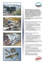
Power Generation<br />
<strong>MAAG</strong> synchronizing clutch coupling type<br />
HS85 installed in a power plant between<br />
the gas turbine and generator.<br />
<strong>The</strong> generator is on line permanently. If<br />
pow er is needed, the gas turbine is started<br />
by its starting system and further accelerated<br />
to full speed. When the gas turbine shaft<br />
overruns the generator shaft, the clutch<br />
engages and power is transmitted. When<br />
pow er is no longer required, the gas turbine<br />
power is reduced to approx. zero, and the<br />
disengage signal is sent to the clutch, which<br />
disengages immediately. <strong>The</strong> gas turbine<br />
is shut down and the generator to rotate,<br />
operating as a synchronous condenser.<br />
<strong>Synchronizing</strong><br />
clutch coupling<br />
type HS85<br />
Gas turbine Generator<br />
Input<br />
(gas turbine)<br />
Spool piece with<br />
synchronizing mechanism<br />
Servo mechanism<br />
Output<br />
(generator)<br />
9
10<br />
<strong>MAAG</strong> synchronizing clutch coupling type<br />
HS85H installed in a power plant between<br />
gas turbine and generator.<br />
As its designation indicates, this type<br />
HS85H is combined with a fluid coupling.<br />
This fluid coupling will be used to start the<br />
gas turbine when the generator is working<br />
as a synchronous condensor. <strong>The</strong> gener ator<br />
rotates at synchronous speed, i. e. 3000<br />
rpm, in the case of a 50 Hz grid, the clutch<br />
coupling is disengaged and the gas turbine<br />
is stationary.<br />
If power is required from the gas turbine,<br />
the turbine is accelerated by filling the fluid<br />
coupling. Above a certain speed, the turbine<br />
accelerates under its own power, after<br />
which the fluid coupling is emptied. <strong>The</strong><br />
<strong>Synchronizing</strong> clutch coupling<br />
type HS85<br />
Special frame<br />
(mounted on site)<br />
turbine accelerates further until it overruns<br />
the generator. <strong>The</strong> clutch coupling engages<br />
automatically. Power can now be transmitted<br />
from the turbine to the generator.<br />
This arrangement avoids the need for an expensive<br />
separate starting device for the gas<br />
turbine.<br />
Fluid<br />
coupling H<br />
<strong>Synchronizing</strong><br />
clutch coupling<br />
type HS85H<br />
Gas turbine Integrated<br />
fluid<br />
coupling<br />
Generator
This is an example of a synchronizing clutch<br />
application in an air storage power plant.<br />
<strong>The</strong> synchronizing clutch coupling type<br />
MS85S is mounted between the gas<br />
turbine (power turbine only) and the generator.<br />
In this case the MStype coupling<br />
has the Sfeature which means that the<br />
cou pling will behave like a rigid coupling<br />
when engaged.<br />
Centrifugal<br />
compressor<br />
Disgengageable<br />
coupling<br />
Generator/<br />
motor<br />
<strong>Synchronizing</strong><br />
clutch coupling<br />
type MS85S<br />
Output<br />
(generator/motor)<br />
Gas Turbine<br />
(power turbine<br />
only)<br />
Input<br />
(gas turbine)<br />
Exploded view of the type<br />
MS85S synchronizing clutch coupling<br />
11
12<br />
Energy Recovery, Combined Cycle Technology,<br />
Cogeneration<br />
This shows a typical energy recovery application<br />
for the type MS14 synchronizing<br />
clutch coupling in a compressor installation<br />
where surplus process gases, instead<br />
of being released by a valve, are used to<br />
drive a gas expander. This gas expander is<br />
cou pled to a centrifugal compressor via the<br />
type MS14 clutch. If no surplus process<br />
gases are available, the gas expander is<br />
automatically disconnected thus avoiding<br />
windage losses in the gas expander.<br />
Output coupling hub<br />
with synchronizing mechanism<br />
(centrifugal compressor)<br />
<strong>Coupling</strong> assembly<br />
Spacer<br />
<strong>Coupling</strong> sleeve<br />
Input coupling<br />
hub (expander)<br />
Steam<br />
turbine<br />
<strong>Synchronizing</strong> clutch<br />
coupling type MS14<br />
Centrifugal<br />
compressor<br />
Gas<br />
expander
This is a typical example of a synchronizing<br />
clutch coupling application in the field of<br />
combined cycle technology in a chemical<br />
plant. Steam is generated by a conventional<br />
boiler, which can be used for the process<br />
technology or power generation. If steam<br />
is available, the steam turbine will be<br />
started and automatically coupled to the<br />
generator.<br />
In the original arrangement, without overrunning<br />
clutch, cooling steam was required<br />
to windmill the steam turbine (no power<br />
generation by steam turbine). By installing<br />
the clutch coupling the steam turbine can<br />
be shut down, no cooling steam is re quired<br />
and overall efficiency is considerably increased.<br />
In this example installation, the<br />
MS36J is electrically insulated and in<br />
Gas turbine Generator Steam turbine<br />
Gearbox<br />
<strong>Synchronizing</strong><br />
clutch coupling<br />
type MS36J<br />
stalled between the steam turbine and the<br />
gener ator. In this particular case the synchronizing<br />
clutch coupling was installed as<br />
a replacement for a gear coupling.<br />
Output coupling<br />
hub with synchronizing<br />
mechanism (generator)<br />
<strong>Clutch</strong> assembly with mounting frame<br />
Spacer<br />
Input<br />
coupling sleeve<br />
(steam turbine)<br />
13
14<br />
Other Applications<br />
<strong>Synchronizing</strong> <strong>Clutch</strong>es for Automatic<br />
Turning Gears Type MS-…-T<br />
<strong>The</strong> <strong>MAAG</strong> synchronizing clutches for<br />
turn ing gears are of simple construction,<br />
suit able for turbomachinery installations,<br />
and combine outstanding reliability with<br />
high torque transmitting capacity.<br />
<strong>The</strong> clutch automatically engages at the<br />
instant the input speed tends to overtake<br />
that of the output shaft. Conversely, the<br />
clutch will automatically disengage when<br />
the output shaft speed exceeds the speed<br />
of the input shaft. A full range of turning<br />
gear clutches is available.<br />
Design principle of a <strong>MAAG</strong> freestanding<br />
synchronizing clutch coupling<br />
for high power transmission<br />
(e. g. 131.5 MW/60 Hz or<br />
125.0 MW/50 Hz)<br />
Output shaft<br />
Free-Standing <strong>Synchronizing</strong><br />
<strong>Clutch</strong> <strong>Coupling</strong>s Type MS-…-E<br />
<strong>The</strong> encased <strong>MAAG</strong> synchronizing clutch<br />
couplings have been developed for installations<br />
where the driving machine has<br />
to be totally isolated for «onsite» maintenance<br />
while the driven machine continues<br />
to rotate. Typical applications for the<br />
encased clutches are fan drives with two<br />
driving machines.<br />
<strong>The</strong> input and output shaft are each supported<br />
by two amply dimensioned bearings.<br />
<strong>The</strong> type MSclutch is mounted inside<br />
the casing between the two shafts. <strong>The</strong><br />
cas ing is of fabricated steel plates. Standard<br />
fle xible couplings such as diaphragm couplings<br />
can be used to connect the clutch<br />
unit to the driving and driven machines.<br />
Automatic turning gear clutch type<br />
MS8T installed in gearbox between<br />
turning gear and pinion shaft<br />
MS clutch<br />
Input shaft
Typical Examples of Applications<br />
ANZAC CODOG gear system<br />
on testbed<br />
<strong>MAAG</strong> synchronizing clutch<br />
type MS-76/E<br />
ANZAC frigate<br />
15
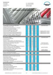
Customer Service / Spare Parts / Maintenance / Testbed<br />
<strong>RENK</strong>-<strong>MAAG</strong> cares for the customer<br />
during and after the sales: Our efficient<br />
sales team is prepared to give<br />
advice regarding new equipment<br />
and original spare parts for couplings<br />
and gearboxes of <strong>MAAG</strong> type.<br />
On-site support is provided worldwide<br />
for all <strong>MAAG</strong>-turbo and Marine<br />
gearboxes by our experienced and<br />
certified field service engineers. Periodical<br />
and/or preventive maintenance<br />
assure the safe and reliable<br />
operation of equipment. Our service<br />
field engineers are at your disposal<br />
for inspections and maintenance.<br />
<strong>RENK</strong>-<strong>MAAG</strong><br />
is at your disposal<br />
Production and other activities are<br />
monitored by the internal quality<br />
assurance system and in strict<br />
compliance with ISO 9001 : 2000.<br />
In case of need to fully refurbish or<br />
revamp a gearbox, coupling or components<br />
at our facility, we provide a<br />
full range of support with the delivery<br />
of a re-warranted unit.<br />
New gearboxes and components<br />
can thoroughly be tested applying<br />
the latest technology in diagnostic<br />
mon itoring equipment for vibration,<br />
temperature and sound.<br />
Test runs of refurbished gearboxes<br />
are also concluded where verification<br />
of repair work must be certified.<br />
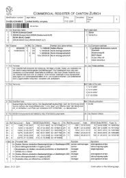
<strong>RENK</strong>-<strong>MAAG</strong> <strong>GmbH</strong><br />
P. O. Box 3068 • Sulzer-Allee 46 • CH-8404 Winterthur<br />
Tel. +41 (0) 52 262 89 88 • Fax +41 (0) 52 262 89 89<br />
info@renk-maag.ch • www.renk-maag.ch