Zetex - AN23 - Zetex SPICE models - understanding ... - Diodes, Inc.
Zetex - AN23 - Zetex SPICE models - understanding ... - Diodes, Inc.
Zetex - AN23 - Zetex SPICE models - understanding ... - Diodes, Inc.

You also want an ePaper? Increase the reach of your titles
YUMPU automatically turns print PDFs into web optimized ePapers that Google loves.
This application note is a guide to the<br />
<strong>understanding</strong> and use of <strong>Zetex</strong> <strong>SPICE</strong><br />
<strong>models</strong>. It includes sections on how<br />
some of these <strong>models</strong> are derived - the<br />
measurements/optimisation necessary,<br />
how to customise <strong>models</strong> for those<br />
cases where a model is not available,<br />
and the limitations to be aware of.<br />
Measurement of Model<br />
Parameters<br />
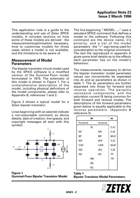
The bipolar transistor circuit model used<br />
by the <strong>SPICE</strong> software is a modified<br />
version of the Gummel-Poon model<br />
formulated in 1970. The schematic of<br />
this model is shown in Figure 1. For a<br />
comprehensive description of the<br />
model, including physical definitions of<br />
the model components, please refer to<br />
Appendix B, references 1 and 2.<br />
Figure 2 shows a typical model for a<br />
<strong>Zetex</strong> bipolar transistor.<br />
Lines beginning with an asterisk indicate<br />
a non-executable comment; so device<br />
details, date of creation, line spaces, and<br />
copyright messages all start with this<br />
symbol.<br />
B<br />
r'b<br />
B'<br />
CJC<br />
CJE<br />
CDC<br />
CDE<br />
Figure 1<br />
Gummel-Poon Bipolar Transistor Model.<br />
E'<br />
C'<br />
C<br />
E<br />
r'c<br />
r'e<br />
<strong>AN23</strong> - 2<br />
Application Note 23<br />
Issue 2 March 1996<br />
The line beginning “.MODEL ....” uses a<br />
standard <strong>SPICE</strong> command that defines a<br />
model to the software. Following this<br />
command are the device name, it’s<br />
polarity, and a list of the model<br />
parameters - the “+” sign being used for<br />
concatenation to the original command.<br />
The text file reproduced in appendix A<br />
gives some brief details as to the effects<br />
each parameter has on the model’s<br />
behaviour.<br />
The measurements necessary to derive<br />
the bipolar transistor model parameter<br />
values can conveniently be separated<br />
into dc and ac parameters as shown in<br />
table 1. The dc parameters are further<br />
separated into those for forward and<br />
reverse operation. The parasitic<br />
resistance components, and the<br />
saturation current IS being common for<br />
both forward and reverse modes. The<br />
descriptions of the forward parameters<br />
given below is equally applicable to the<br />
reverse parameters. (Appendix B<br />
reference 3).<br />
dc ac<br />
forward reverse<br />
IS CJC<br />
NF NR CJE<br />
BF BR MJC<br />
IKF IKR VJC<br />
VAF VAR MJE<br />
ISE ISC VJE<br />
NE NC TF<br />
RB<br />
RE<br />
RC<br />
TR<br />
Table 1<br />
Bipolar Transistor Model Parameters.