CVB-EX - Gimota
CVB-EX - Gimota
CVB-EX - Gimota

Create successful ePaper yourself
Turn your PDF publications into a flip-book with our unique Google optimized e-Paper software.
VD 09/2006<br />
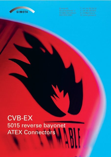
<strong>CVB</strong>-<strong>EX</strong><br />
5015 reverse bayonet<br />
AT<strong>EX</strong> Connectors<br />
<strong>Gimota</strong> AG<br />
Chrummacherstr. 3<br />
CH-8954 Geroldswil<br />
SWITZERLAND<br />
T: +41 44 749 30 10<br />
F: +41 44 749 3015<br />
E: info@gimota.ch<br />
W: www.gimota.ch<br />
1
2<br />
VD 09/2006
VD 09/2006<br />
<strong>CVB</strong>-<strong>EX</strong> <strong>CVB</strong>-<strong>EX</strong><br />
5015 reverse bayonet AT<strong>EX</strong> Connectors<br />
5015 reverse bayonet AT<strong>EX</strong> Connectors<br />
Standards<br />
Certification<br />
Standards<br />
Standards: 94/9/EC (AT<strong>EX</strong>) Directive<br />
According to European Standards<br />
Certification<br />
Certification:<br />
94/9/EC EN 60079-0<br />
94/9/EC (AT<strong>EX</strong>)<br />
EN 60079-1 (AT<strong>EX</strong>) Directive Directive<br />
EN 61241-0<br />
According EN 61241-1 to European Standards<br />
EN 60079-0<br />
Certificate EN ICEPI 60079-0 08 AT<strong>EX</strong> 03C002X<br />
EN 60079-1 EN 60079-1<br />
EN 61241-0 EN I M2 61241-0 Ex d I<br />
EN 61241-1 EN 61241-1<br />
II 2G Ex d IIC<br />
Certificate II 2GD ICEPI Ex d IIC 08 tD AT<strong>EX</strong> A21 IP66/IP67 03C002X<br />
<strong>CVB</strong>-<strong>EX</strong><br />
5015 reverse bayonet AT<strong>EX</strong> Connectors<br />
According to European Standards<br />
Certificate ICEPI 08 AT<strong>EX</strong> 03C002X<br />
I M2 Ex d I<br />
II 2G Ex d IIC<br />
II 2GD Ex d IIC tD A21 IP66/IP67<br />
<strong>Gimota</strong> AG<br />
Chrummacherstr. 3<br />
CH-8954 Geroldswil<br />
SWITZERLAND<br />
T: +41 44 749 30 10<br />
F: +41 44 749 3015<br />
E: info@gimota.ch<br />
W: www.gimota.ch<br />
Application area<br />
Suitable for surface applications<br />
Group II Zones Application 1, 21, 2 and area 22 (Gas and Dust)<br />
Gas Application Group IIC<br />
Suitable area for surface applications<br />
Suitable for Group underground II Zones applications 1, 21, 2 and 22 (Gas and Dust)<br />
Group Suitable I category for surface M2 applications<br />
Group II Zones Gas Group 1, 21, IIC 2 and 22 (Gas and Dust)<br />
Can be installed on devices and enclosures<br />
designed with following type of protection<br />
Gas Group Suitable IIC for underground applications<br />
Explosion proof Group Ex I category d – EN60079-1 M2<br />
Increased Suitable safety for underground Ex e – EN60079-7 applications<br />
Intrinsic Group safety I category Can be Ex installed M2 i – EN60079-11 on devices and enclosures<br />
Pressurization designed Ex p with – EN60079-2 following type of protection<br />
Can be installed on devices and enclosures<br />
designed Explosion with following proof type Ex of d protection – EN60079-1<br />
Increased safety Ex e – EN60079-7<br />
Explosion Intrinsic proof safety Ex d Ex – EN60079-1 i – EN60079-11<br />
Increased Pressurization safety Ex e Ex – EN60079-7 p – EN60079-2<br />
Intrinsic safety Ex i – EN60079-11<br />
Pressurization Ex p – EN60079-2<br />
Dynamin s.r.l.<br />
T : +39 02 901 11 052<br />
Piazza Venini, 8 F : +39 02 902 14 99<br />
20010 Vittuone <strong>CVB</strong>-<strong>EX</strong> (Mi) E : info@dynamin-srl.it<br />
ITALIA<br />
W: www.dynamin-srl.it<br />
5015 reverse bayonet AT<strong>EX</strong> Connectors<br />
3
4<br />
Approval:<br />
Reverse bayonet coupling system<br />
VD 09/2006<br />
General Characteristi<br />
o Working Temp<br />
o Protection deg<br />
60529<br />
o Hard anodized<br />
brass<br />
o Hundreds of a<br />
Mil-C-5015<br />
o from size 16s t<br />
o 2 to 150 conta<br />
o Crimp or solde<br />
o Safety lock by<br />
socket screw<br />
The reverse bayonet connectors are derived from the threaded Mil-C-5015 s<br />
anti-vibration resistance.<br />
In this series the coupling system is composed of 3 bayonet ramps (see draw<br />
side of the receptacle connector and 3 stainless steel studs mounted inside th
VD 09/2006<br />
o Working Temperature: -40ºC / +135ºC<br />
General Characteristics<br />
o Protection degree IP66/IP67 according to EN<br />
60529<br />
o Working Temperature: -40ºC / +135ºC<br />
o Hard anodized aluminium alloy or nickel plated<br />
brass<br />
o Protection degree IP66/IP67 according to o EN60529 Hundreds of available arrangements according to<br />
o Hard anodized aluminium alloy or nickel plated Mil-C-5015 brass<br />
o from size 16s to size 40<br />
o Hundreds of available arrangements according o 2 to 150 to Mil-C-5015<br />
contacts<br />
o from size 16s to size 40<br />
o Crimp or solder contacts<br />
o 2 to 150 contacts<br />
o Safety lock by threaded stainless steel hexagon<br />
o Crimp or solder contacts<br />
socket screw<br />
o Safety lock by threaded stainless steel hexagon socket screw<br />
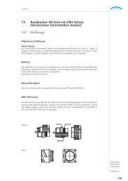
Reverse bayonet coupling system<br />
The reverse bayonet connectors are derived from the threaded Mil-C-5015 series<br />
to provide faster coupling and anti-vibration resistance.<br />
In this series the coupling system is composed of 3 bayonet ramps (see drawing<br />
below) machined on the external side of the receptacle connector and 3 stainless<br />
Reverse steel bayonet studs coupling mounted system inside the plug connector’s coupling nut.<br />
The reverse bayonet connectors are derived from the threaded Mil-C-5015 series to provide faster coupling and<br />
anti-vibration resistance.<br />
In this series the coupling system is composed of 3 bayonet ramps (see drawing below) machined on the external<br />
side of the receptacle connector and 3 stainless steel studs mounted inside the plug connector’s coupling nut.<br />
Characteristic<br />
Characteristics<br />
Advantages against the thread coupling<br />
To mate connectors rotate coupling-nut 120° only Fast coupling and uncoupling<br />
Audible, visible and tactile mating. Security of coupling is guaranteed and consequently<br />
To mate connectors rotate coupling-nut 120° improved only audible, reliability visible and tactile ma-<br />
The bayonet ting. ramps The bayonet are resistant ramps to damage are resistant to damage Higher number of mating cycles<br />
Van-System s.r.l.<br />
Via zambeletti, 19<br />
20021 Baranzate (Mi)<br />
ITALIA<br />
Advantages against the thread coupling<br />
T : +39 02 356 993 1<br />
F : +39 02 38 204 205<br />
E : info@vansystem.eu<br />
W: www.vansystem.eu<br />
General Characteristics<br />
Dynamin s.r.l.<br />
Piazza Venini, 8<br />
20010 Vittuone (Mi)<br />
ITALIA<br />
o Fast coupling and uncoupling<br />
o Security of coupling is guaranteed and consequently improved reliability<br />
o Higher number of mating cycles<br />
T : +39 02 901 11 052<br />
F : +39 02 902 14 99<br />
E : info@dynamin-srl.it<br />
W: www.dynamin-srl.it<br />
5
6<br />
Contact rating<br />
Contact Size Pin diameter mm. Max. operating<br />
current (A)<br />
20 1 3<br />
18 1.42 6<br />
16s 1.58 10<br />
16 1.58 10<br />
12 2.38 20<br />
8 3.6 40<br />
4 5.7 63<br />
0 9.05 125<br />
Available arrangemets<br />
5015 arrangements normally available<br />
VD 09/2006<br />
Arrangement totct 0 4 8 12 16 17 18<br />
16S-1 7 7<br />
16S-4 2 2<br />
16S-5 3 3<br />
16S-8 5 5<br />
18-1 10 10<br />
18-3 2 2<br />
18-4 4 4<br />
18-8 8 1 7<br />
18-9 7 2 5<br />
18-10 4 4<br />
18-11 5 5<br />
18-12 6 6<br />
18-19 10 10<br />
18-20 5 5<br />
18A-5 5 5<br />
20-3 3 3<br />
20-4 4 4<br />
20-7 8 8<br />
20-11 13 13<br />
20-15 7 7<br />
20-18 9 3 6<br />
20-24 4 2 2<br />
20-27 14 14<br />
20-29 17 17<br />
20-33 11 11<br />
20A-48 19 19<br />
20B-8 8 4 4
VD 09/2006<br />
<strong>CVB</strong>-<strong>EX</strong> 09<br />
<strong>CVB</strong>-<strong>EX</strong> 09 can be screwed indirectly the equipment enclosure or fixed into a wall<br />
trough a nut.<br />
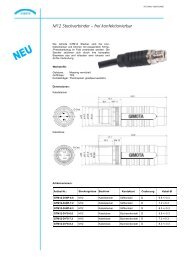
<strong>CVB</strong>-<strong>EX</strong> 09<br />
Provided<br />
<strong>CVB</strong>-<strong>EX</strong><br />
with<br />
09 can<br />
metric<br />
be screwed<br />
thread<br />
indirectly the equipment enclosure or fixed into a wall trough a nut.<br />
Provided with metric thread<br />
<strong>CVB</strong>-<strong>EX</strong> 09<br />
<strong>CVB</strong>-<strong>EX</strong> 09 can be screwed indirectly the equipment enclosure or fixed into a wall trough a nut.<br />
Provided with metric thread<br />
Size A B C L D E F G H I<br />
16s<br />
Size 18<br />
37<br />
40 A<br />
32<br />
34 B<br />
M25x1.5<br />
M28x1.5 C<br />
3.1<br />
3.1 L<br />
27.4<br />
30.8 D<br />
33<br />
E 38<br />
40.6<br />
F 45.1 G<br />
6.5<br />
8 H<br />
53.8<br />
66.8 I<br />
16<br />
21.7<br />
20 44 40 M32x1.5 3.1 34.2 40.5 45.1 8 66.8 21.7<br />
16s 37 32 M25x1.5 3.1 27.4 33 40.6 6.5 53.8 16<br />
18 <strong>CVB</strong>-<strong>EX</strong> 04 40 34 M28x1.5 3.1 30.8 38 45.1 8 66.8 21.7<br />
20 <strong>CVB</strong>-<strong>EX</strong> 09 can 44be screwed 40 M32x1.5 indirectly the 3.1 equipment 34.2 enclosure. 40.5 45.1<br />
Provided with NPT thread<br />
8 66.8 21.7<br />
Size A B C L D E F G H I<br />
16s 37 32 M25x1.5 3.1 27.4 33 40.6 6.5 53.8 16<br />
18 40 34 M28x1.5 3.1 30.8 38 45.1 8 66.8 21.7<br />
20 44 40 M32x1.5 3.1 34.2 40.5 45.1 8 66.8 21.7<br />
<strong>CVB</strong>-<strong>EX</strong> 04<br />
<strong>CVB</strong>-<strong>EX</strong> 09 can be screwed indirectly the equipment enclosure.<br />
Provided <strong>CVB</strong>-<strong>EX</strong> with 04 NPT thread<br />
<strong>CVB</strong>-<strong>EX</strong> 09 can be screwed indirectly the equipment enclosure.<br />
Provided with NPT thread<br />
Size A B C L D E F G H I<br />
16s 37 32 3.1 27.4 33 40.6 6.5 53.8 16<br />
18 40 34 ¾” NPT 3.1 30.8 38 45.1 8 66.8 21.7<br />
20 44 40 3.1 34.2 40.5 45.1 8 66.8 21.7<br />
Size A B C L D E F G H I<br />
16s<br />
Size 18<br />
37<br />
40 A<br />
32<br />
34 B ¾” C NPT<br />
3.1<br />
3.1 L<br />
27.4<br />
30.8 D<br />
33<br />
E 38<br />
40.6<br />
F 45.1 G<br />
6.5<br />
8 H<br />
53.8<br />
66.8 I<br />
16<br />
21.7<br />
20 44<br />
16s Van-System s.r.l. 37<br />
40<br />
32 T : +39 02 356 993 1<br />
3.1<br />
3.1<br />
34.2<br />
27.4<br />
40.5 45.1<br />
33 Dynamin 40.6 s.r.l. 6.5<br />
8 66.8 21.7<br />
53.8T : +39 1602<br />
901 11 052<br />
Via zambeletti, 19<br />
18 20021 Baranzate (Mi) 40<br />
F : +39 02 38 204 205<br />
34 E : info@vansystem.eu ¾” NPT 3.1 30.8 38<br />
Piazza Venini, 8<br />
F : +39 02 902 14 99<br />
20010 45.1Vittuone 8 (Mi) 66.8E : info@dynamin-srl.it<br />
21.7<br />
ITALIA<br />
W: www.vansystem.eu<br />
ITALIA<br />
W: www.dynamin-srl.it<br />
20 44 40 3.1 34.2 40.5 45.1 8 66.8 21.7<br />
Van-System s.r.l.<br />
Via zambeletti, 19<br />
20021 Baranzate (Mi)<br />
ITALIA<br />
T : +39 02 356 993 1<br />
F : +39 02 38 204 205<br />
E : info@vansystem.eu<br />
W: www.vansystem.eu<br />
Dynamin s.r.l.<br />
Piazza Venini, 8<br />
20010 Vittuone (Mi)<br />
ITALIA<br />
T : +39 02 901 11 052<br />
F : +39 02 902 14 99<br />
E : info@dynamin-srl.it<br />
W: www.dynamin-srl.it<br />
7
8<br />
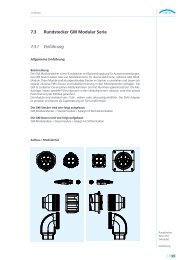
<strong>CVB</strong>-<strong>EX</strong> 02<br />
Flange mounted receptacle<br />
<strong>CVB</strong>-<strong>EX</strong> 02<br />
Flange mounted receptacle<br />
<strong>CVB</strong>-<strong>EX</strong> 02<br />
Flange mounted receptacle<br />
VD 09/2006<br />
Size A B C L D E F G H I<br />
16s 32.5 24.6 22.4 3.1 27.4 33 3.2 16<br />
18 34.9 27 25.6 3.1 30.8 38 45.1 4 63.1 21.7<br />
20 38.1 29.4 28.8 3.1 34.2 40.5 45.1 4 63.1 21.7<br />
Size A B C L D E F G H I<br />
16s 32.5 24.6 22.4 3.1 27.4 33 3.2 16<br />
18 34.9 27 25.6 3.1 30.8 38 45.1 4 63.1 21.7<br />
20 <strong>CVB</strong>-<strong>EX</strong> 06 38.1<br />
Inline Plug<br />
29.4 28.8 3.1 34.2 40.5 45.1 4 63.1 21.7<br />
Size A B C L D E F G H I<br />
16s 32.5 24.6 22.4 3.1 27.4 33 3.2 16<br />
18 34.9 27 25.6 3.1 30.8 38 45.1 4 63.1 21.7<br />
20 38.1 29.4 28.8 3.1 34.2 40.5 45.1 4 63.1 21.7<br />
<strong>CVB</strong>-<strong>EX</strong> 06<br />
Inline Plug<br />
<strong>CVB</strong>-<strong>EX</strong> 06<br />
Inline Plug<br />
SIZE A B C D E F<br />
16S 29.8 43.2 38 33.5 27.4<br />
18 33 50.2 41.6 41.5 30.8<br />
20 36.5 5.02 45 41.5 34.2<br />
Van-System s.r.l. T : +39 02 356 993 1<br />
Dynamin s.r.l.<br />
T : +39 02 901 11 052<br />
Via zambeletti, 19<br />
SIZE A<br />
20021 Baranzate (Mi)<br />
16S ITALIA<br />
29.8<br />
18 33<br />
F : +39 02 38 204 205<br />
B<br />
E : info@vansystem.eu<br />
W: www.vansystem.eu 43.2<br />
50.2<br />
C<br />
38<br />
41.6<br />
Piazza Venini, 8<br />
D E<br />
20010 Vittuone (Mi)<br />
33.5 ITALIA<br />
41.5<br />
F : +39 02 902 14 99<br />
F<br />
E : info@dynamin-srl.it<br />
W: www.dynamin-srl.it 27.4<br />
30.8<br />
20 36.5 5.02 45 41.5 34.2<br />
Size A B C D E F<br />
16S 29.8 43.2 38 33.5 27.4<br />
18 33 50.2 41.6 41.5 30.8<br />
20 36.5 5.02 45 41.5 34.2<br />
Van-System s.r.l.<br />
Via zambeletti, 19<br />
20021 Baranzate (Mi)<br />
ITALIA<br />
T : +39 02 356 993 1<br />
F : +39 02 38 204 205<br />
E : info@vansystem.eu<br />
W: www.vansystem.eu<br />
Dynamin s.r.l.<br />
Piazza Venini, 8<br />
20010 Vittuone (Mi)<br />
ITALIA<br />
T : +39 02 901 11 052<br />
F : +39 02 902 14 99<br />
E : info@dynamin-srl.it<br />
W: www.dynamin-srl.it
Serie Type Shell<br />
VD 09/2006<br />
Material<br />
Serie<br />
<strong>CVB</strong>-<strong>EX</strong> Surface applications<br />
<strong>CVB</strong>M-<strong>EX</strong> Underground Applications<br />
Type<br />
1 Inline receptacle UNEF thread<br />
2 Flanged panel mount<br />
3 Flanged rear panel mount<br />
4 NPT Threaded panel mount<br />
6 Inline plug<br />
7 Panel Jamnut<br />
9 Inline receptacle Metric ISO 261 thread<br />
K Inline receptacle UNI 6125 7/1 Rc thread<br />
R Inline receptacle UNI 338 7/1 Rp thread<br />
Shell material<br />
A Alluminium Anodized<br />
O Nickel palted brass<br />
S AISI 316<br />
C Nickel plated stainless steel<br />
B Bronze<br />
Working temperature<br />
1 -20°C/100°C<br />
2 -20°C/135°C<br />
3 -40°C/100°C<br />
4 -40°C/135°C<br />
Arrangement<br />
See page 2<br />
Contact type<br />
P Pin Contact<br />
S Socket contact<br />
Service rating<br />
I Max 200 Vcc/ca<br />
A Max 500 Vca, 700Vcc<br />
Backshell Identification<br />
- Absent no Backshell<br />
000 Standard<br />
001-999 Special<br />
Cable assembly ID<br />
- Absent no cable assembly<br />
0000 Standard cable assembly<br />
0001-9999 Cable assembly ID<br />
Cable termiantion<br />
Working<br />
temp.<br />
Arrangement<br />
G Flexible conduit<br />
S Waterproof cable clamp (MS 3057-C)<br />
E Cable clamp Ex e<br />
D Cable clamp Ex d<br />
Contact<br />
type<br />
Service<br />
rating<br />
Back<br />
shell ID<br />
Cable assembly<br />
ID<br />
<strong>CVB</strong>-XE 6 A 1 18-20 P A 0 2 S<br />
<strong>CVB</strong>M-<strong>EX</strong> 7 O 2 18-20 P A 0 2 D<br />
Cable<br />
termination<br />
9
10<br />
<strong>CVB</strong>-<strong>EX</strong><br />
5015 reverse bayonet AT<strong>EX</strong> Connectors<br />
Standards<br />
Certification<br />
94/9/EC (AT<strong>EX</strong>) Directive<br />
According to European Standards<br />
EN 60079-0<br />
EN 60079-1<br />
EN 61241-0<br />
EN 61241-1<br />
Certificate ICEPI 08 AT<strong>EX</strong> 03C002X<br />
I M2 Ex d I<br />
II 2G Ex d IIC<br />
II 2GD Ex d IIC tD A21 IP66/IP67<br />
<strong>Gimota</strong> AG<br />
Chrummacherstr. 3<br />
CH-8954 Geroldswil<br />
SWITZERLAND<br />
T: +41 44 749 30 10<br />
F: +41 44 749 3015<br />
E: info@gimota.ch<br />
W: www.gimota.ch<br />
Application area<br />
Suitable for surface applications<br />
Group II Zones 1, 21, 2 and 22 (Gas and Dust)<br />
Gas Group IIC<br />
Suitable for underground applications<br />
Group I category M2<br />
Can be installed on devices and enclosures<br />
designed with following type of protection<br />
Explosion proof Ex d – EN60079-1<br />
Increased safety Ex e – EN60079-7<br />
Intrinsic safety Ex i – EN60079-11<br />
Pressurization Ex p – EN60079-2<br />
VD 09/2006<br />
Dynamin s.r.l.<br />
T : +39 02 901 11 052<br />
Piazza Venini, 8 F : +39 02 902 14 99<br />
20010 Vittuone <strong>CVB</strong>-<strong>EX</strong> (Mi) E : info@dynamin-srl.it<br />
ITALIA<br />
W: www.dynamin-srl.it<br />
5015 reverse bayonet AT<strong>EX</strong> Connectors