TDRSS DEMAND ACCESS SERVICE: APPLICATION OF ...
TDRSS DEMAND ACCESS SERVICE: APPLICATION OF ...
TDRSS DEMAND ACCESS SERVICE: APPLICATION OF ...

Create successful ePaper yourself
Turn your PDF publications into a flip-book with our unique Google optimized e-Paper software.
3<br />
Paper ID: 5a003<br />
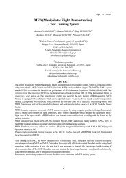
Figure 2 provides an overview of the currently existing <strong>TDRSS</strong> MA return link architecture showing relevant<br />
equipment within a single WSC SGLT along with an outline of the data flow to the user control centers. Within<br />
the SGLT, the 30 FDM MA return channels from a single TDRS are first separated into 30 analog channels at a<br />
common intermediate frequency by the Element Separator. Next, each of the 30 channels is digitized within the<br />
A/D Quad Splitter and output as two channels of 8-bit digital data representing In-phase and Quadrature<br />
components sampled at 8.5 Msps. These 60 digital channels are then distributed to each beamformer/receiver.<br />
As illustrated, a single WSC SGLT supporting MA return service contains six beamformer/receiver<br />
combinations. Of these six, five are made available for user service and one set of equipment is dedicated to<br />
array calibration. Thus five simultaneous MA return link users can be supported and each user receives the full<br />
gain of the TDRS phased array. These five links per TDRS have been fully adequate to support the community<br />
of orbiting spacecraft using an operations concept based on prior scheduling. But, as described below, new<br />
operations concepts become feasible if more return links can be provided.<br />
3 THE RETURN LINK DA CONCEPT<br />
3.1 STATEMENT <strong>OF</strong> NEED<br />
The evolution towards smaller, lower cost space missions has led to an increased user need for streamlined<br />
mission support and a strong desire for autonomous spacecraft operation. Toward these goals, NASA GSFC has<br />
6<br />
6<br />
Amplify/<br />
Convert to IF<br />
Element<br />
Separator<br />
A/D Quad<br />
Splitter<br />
MA Return<br />
Link Equipment<br />
30<br />
2 Beamformer<br />
1<br />
2 1 Integrated<br />
Receiver<br />
Controller<br />
SGLT<br />
Control/Data<br />
Interface<br />
&<br />
Data<br />
Handling<br />
Functions<br />
GSFC<br />
Network<br />
Control<br />
User Control<br />
Centers<br />
Figure 2: The Existing MA Return Link Architecture