TDRSS DEMAND ACCESS SERVICE: APPLICATION OF ...
TDRSS DEMAND ACCESS SERVICE: APPLICATION OF ...
TDRSS DEMAND ACCESS SERVICE: APPLICATION OF ...

Create successful ePaper yourself
Turn your PDF publications into a flip-book with our unique Google optimized e-Paper software.
1<br />
2<br />
•<br />
•<br />
•<br />
30<br />
A /<br />
D<br />
Q UADSPLITTER<br />
I,Q-1<br />
I,Q-6<br />
I,Q-25<br />
I,Q-30<br />
A/D Quad digitizes<br />
into 30 channels each<br />
@:<br />
1. I &Q<br />
2. 8 bits<br />
3. Rate = 8.5 MHz<br />
EMC Node<br />
Board -1<br />
(Mux)<br />
•<br />
•<br />
•<br />
EMC Node<br />
Board -5<br />
(Mux)<br />
1.0625<br />
Gbps<br />
1<br />
5<br />
Network<br />
Transparent<br />
Switch (NTS)<br />
‘5’ to 15x’5’<br />
(Creates 15<br />
copies)<br />
EMC Node Board<br />
Muxes 6 Channel I,Q<br />
pairs<br />
= 6x(8+8+1)x8.5 MHz<br />
+ Overhead<br />
= 1.0625 Gbps<br />
1<br />
2<br />
15<br />
5 x1.0625<br />
Gbps<br />
•<br />
•<br />
•<br />
5<br />
5<br />
EMC IBUG<br />
5<br />
To other<br />
IBUGs<br />
EMC NTS<br />
Provides 15<br />
sets of the<br />
5 1.0625<br />
Gbps Data<br />
5<br />
Network<br />
Transparent<br />
Switch (NTS)<br />
‘5’ to 5x’5’<br />
(Creates 5<br />
Copies)<br />
IBUG NTS<br />
Provides 5<br />
sets of the<br />
5 1.0625<br />
Gbps Data<br />
5 x1.0625<br />
Gbps<br />
5<br />
1<br />
Transition<br />
Module -1<br />
(Serial to<br />
Parallel)<br />
Paper ID: 5a003<br />
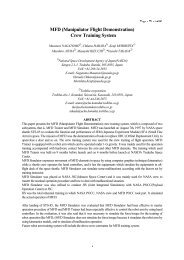
The NTS, in conjunction with modern high speed digital processing, greatly facilitates the beamformer<br />
implementation. A single EMC can support fifteen IBUGs for a total of 75 IBUs in the illustrated configuration.<br />
It is also possible, however, to use a single output from the EMC Network Transparent Switch transmitter to feed<br />
a distribution unit (based again on the same NTS switch) that regenerates the data for transmission to still more<br />
IBUGs. This flexible architecture can support hundreds of beamformers per SGLT – far more than are currently<br />
anticipated.<br />
Demand Access demodulators, currently being prototyped, will also be relatively inexpensive and much smaller<br />
than the current units and will also offer some performance improvements relative to the current WSC<br />
demodulators. Not only will the demodulator realize cost improvements due to advances in technology since the<br />
1980s, the relatively large number of demodulators that will be produced will lower production costs by<br />
distributing non-recurring engineering costs over more units.<br />
One potential performance gain is in acquisition time. The ongoing NASA demodulator prototyping effort has<br />
centered around Charge Coupled Device (CCD) technology which allows rapid PN code correlation evaluations<br />
in the analog domain.<br />
Figure 4 illustrates the planned architecture of the new beamformers and demodulators within an SGLT of the<br />
WSC. The existing A/D Quad Splitters of the WSC have spare outputs available for connection of the new<br />
equipment. Existing beamformers and receivers within the WSC will not be affected by the service expansion.<br />
5<br />
5<br />
•<br />
•<br />
•<br />
Transition<br />
Module -5<br />
(Serial to<br />
Parallel)<br />
1<br />
•<br />
•<br />
20 IBU -1<br />
5<br />
•<br />
20<br />
(Weight<br />
& Sum)<br />
20 Parallel<br />
Lines Each<br />
53.125 MHz<br />
1<br />
•<br />
•<br />
20 IBU -5<br />
5<br />
•<br />
20<br />
(Weight<br />
& Sum)<br />
Transition Module<br />
Converts Serial to 20<br />
bit Parallel<br />
Reduces each 1.0625<br />
Gbps to 20 53.125 MHz<br />
lines<br />
Figure 3: The Beamformer Signal Multiplexing Architecture<br />
•<br />
•<br />
•<br />
IBU<br />
Combines all<br />
30 channels;<br />
Output is a 6<br />
MHz Signal