HP 4280A 1MHz C Meter / C-V Plotter - TekNet Electronics
HP 4280A 1MHz C Meter / C-V Plotter - TekNet Electronics
HP 4280A 1MHz C Meter / C-V Plotter - TekNet Electronics

Create successful ePaper yourself
Turn your PDF publications into a flip-book with our unique Google optimized e-Paper software.
H428OA Applications<br />
l capacitance and Conductance With or Without<br />
Constant DC Bias<br />
<strong>HP</strong>’s <strong>4280A</strong> <strong>1MHz</strong> C <strong>Meter</strong>/C-V <strong>Plotter</strong> can measure and<br />
display capacitance and conductance. A 1 MHz test signal with<br />
level of 1OmVrms or 30mVrms is used.<br />
Internal DC bias ( f 1OOV) can be applied when needed.<br />
4280 Front Panel Displays C,G and DC bias<br />
n Test Floating and Grounded Devices<br />
Both Floating and Grounded devices can be tested. This<br />
is important because wafer probers will have either floating or<br />
grounded chucks. Both configurations are in common use.<br />
n capacitance and Conductance Using Staircase<br />
Bias Sweep<br />
4280’s built-in + IOOV DC bias supply can be controlled<br />
from the front panel to sweep in staircase fashion. Capacitance<br />
and conductance can be measured at each step.<br />
m Hard Copy Output<br />
C-V and G-V measurements require no external equipment<br />
and are internally synchronized. Results can be output to analog<br />
X-Y recorders or to computers via <strong>HP</strong>-IB (IEEE 488).<br />
n Capacitance and Conductance vs. Time<br />
(Pulse Bias)<br />
Minority carrier lifetime and surface generation velocity in<br />
MIS structures can be obtained using C-t results. <strong>4280A</strong> uses<br />
two different C-t methods depending on measurement resolu-<br />
tion required on the time axis.<br />
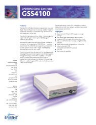
Delay time is the time between measurements. When delay<br />
time is set to 10 milliseconds or greater, the <strong>4280A</strong> will apply<br />
a single pulse to the device under test. Then a BURST of<br />
measurements are made.<br />
START<br />
Time (5) 4<br />
STOP<br />
When delay time is less than 10 milliseconds, an external<br />
pulse generator like <strong>HP</strong>’s 8112A must be used. The external<br />
pulse generator applies repetitive pulses to the device under<br />
test. The <strong>4280A</strong> makes a single measurement after each pulse.<br />
In the SAMPLING MODE, the <strong>4280A</strong> provides synchronization<br />
signals to the external pulse generator.<br />
Deep Level Transcient Spectroscopy<br />
(DL TS) - Example of Pulse Bias Application<br />
DLTS is used to analyze semiconductor imperfections which<br />
effect IC performance. Small imperfection concentrations which<br />
are too small for analysis by C-V techniques can often be analyz-<br />
ed by DLTS.<br />
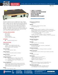
High speed Gt testing and variable supercooled temperature<br />
are major requirements of DLTS test systems. Shown here is<br />
system hardware including <strong>HP</strong>’s <strong>4280A</strong> for Gt testing with<br />
pulses of IOms to 32 set in duration. <strong>HP</strong>’s 8112A pulse gen-<br />
erator is added when pulse duration shorter than 10m set is<br />
required.<br />
DLTS is a high-frequency capacitance transient thermal<br />
scanning method useful for observing a wide variety of traps<br />
in semiconductors. This new technique, aimed at studying these<br />
centers, uses the capacitance of a p-n junction or Schottky bar-<br />
rier as a probe to monitor the changes in the charge state of<br />
the centers. Complete Gt characteristics are obtained at multi-<br />
ple supercooled temperatures.<br />
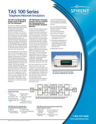
Real devices have multiple trap levels and different trap<br />
concentrations. Resulting DLTS curve has multiple peaks as<br />
shown below.<br />
Temperature (deg C)<br />
Important parameters which can be derived from DLTS in-<br />
clude: 1) surface state density, 2) trap concentration, 3) energy<br />
level of traps, and 4) trap capture cross section.<br />
Advantages offered by <strong>HP</strong>’s <strong>4280A</strong> are to expand the range<br />
of analysis to shallower energy levels by offering resolution to<br />
1 O,us when synchronized to an external pulse generator like <strong>HP</strong>’s<br />
8112A.
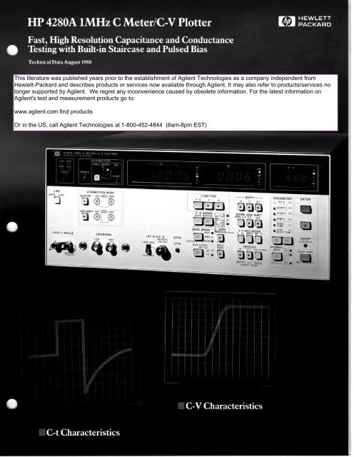
<strong>HP</strong>’S <strong>4280A</strong> Offers New Measurement C;<br />
Wntroduction<br />
Hewlett-Packard’s Model <strong>4280A</strong> 1 MHz C <strong>Meter</strong>/C-V<br />
<strong>Plotter</strong> offers new measurement capability and flexibility<br />
for the design and production of IC’s. Benefits are im-<br />
proved IC quality and improved engineering productivity.<br />
<strong>HP</strong>’s <strong>4280A</strong> has capability previously requiring the<br />
following complicated test set up: 1) capacitancelconduc-<br />
tance meter, 2) function generator, and 3) computer for<br />
test synchronization.<br />
New measurement capability is featured in transient<br />
C-t measurements with 10 microsecond resolution. Such<br />
testing is used to analyze deep level impurity concentra-<br />
tions which effect IC performance. Transient C-t resolu-<br />
tion of 10 microseconds is up to 1000 times better than<br />
ever before available. <strong>4280A</strong> features 10ms C-t resolu-<br />
tion using internal pulse generator. Add <strong>HP</strong> 8112A pulse<br />
generator or equivalent to achieve 10,~s resolution.<br />
Convenience features include the ability to test both<br />
floating and grounded devices. Also 428OA’s has capabili-<br />
ty to compensate a wide range of stray impedances. This<br />
helps eliminate the effect of test fixture residuals.<br />
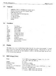
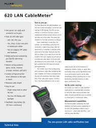
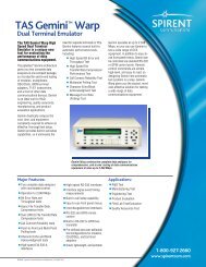
W428OA Front Panel<br />
Features<br />
1 <strong>HP</strong>-IB - Construct Your Own System<br />
Standard on <strong>4280A</strong>, <strong>HP</strong>-IB can help you construct an automatic<br />
system. Such systems are used in applications ranging from<br />
materials research, device R&D, process engineering, wafer pro-<br />
duction and quality assurance.<br />
2 Residual Compensation and Capacitance Offset<br />
Compensate test fixture residuals including up to 5 meters of stan-<br />
dard cable (<strong>HP</strong> P/N 81204195). Also use with Option 001 when off-<br />
setting large values of capacitance to obtain extra digit of resolu-<br />
tion on 100pFllnF ranges.<br />
3 Capacitance Digital Display<br />
Standard capacitance display resolution will be 3% digits or 4%<br />
digits depending on test conditions. Option 001 features 5% digit<br />
capacitance resolution using capacitance offset function. This<br />
display also can show deviation.<br />
4 Wide Capacitance Measurement Range<br />
Capacitance measurement range is from 0.001 pF to 1 .QOOOnF.<br />
5 Conductance Digital Display<br />
Standard conductance display resolution will be 3% digits or 4%<br />
digits depending on test conditions. This display also shows<br />
deviation.<br />
6 Wide Conductance Measurement Range<br />
Conductance measurement range is from 0.01~5 to 12.000mS.<br />
7 DC Bias and Time Display<br />
DC bias parameters in volts or time in seconds is displayed depen-<br />
ding on operating mode.<br />
8 Wide Range of DC Bias and Time<br />
DC bias can be varied in + IOOV range. Bias can be 1) constant,<br />
2) staircase sweep (C/G-V) or 3) pulsed (C/G-t).<br />
V-t display shows values of voltage staircase sweep parameters<br />
in C/G-V modes. These parameters include hold time, and step delay<br />
time. V-t display also shows C/G-t parameters like delay time.<br />
3<br />
OFFn nON &OATlNG<br />
cl<br />
:42V = MAXA UNKNOWN<br />
9 Enter Numedc Values of Voltage and Time<br />
After selecting bias and time parameters and keying in numeric<br />
values, this key enters value into <strong>4280A</strong> memory.<br />
10 Numeric Data Ready to Enter<br />
This LED must be lit before numeric sweep parameter can be<br />
entered.<br />
11 Sweep StartLStop<br />
Start/Stop key controls DC bias and time sweep output. V output<br />
LED lights when bias voltage is applied.<br />
12 Se/act Sweep Parameter or Constant DC Bias<br />
Use up/down keys to select constant DC bias voltage or time sweep<br />
parameter. Enter numeric values using numeric keys.<br />
13 Select Bias Mod&Limit Output Voltage%ld Range<br />
Multi function key selects DC bias mode. Also allows entry of DC<br />
bias voltage limit from numeric keys and acts as Range Hold key.<br />
14 Dispfay Deviation, Percent or Deviation Percent<br />
Perform math operations and display results on C/G displays.<br />
15 Change Number of Display D&its<br />
Reduce number of display counts to less than 1000. Use before<br />
X-Y recording<br />
16 Setup X-Y Recorder<br />
Analog output voltage represents C/G display counts and DC<br />
bias/time sweep. Establish origin and size of X-Y plotting area.<br />
26<br />
R6<br />
MC<br />
Tc<br />
meni<br />
Func<br />
Th<br />
millis<br />
parer<br />
MC<br />
MC<br />
2<br />
W<br />
M<br />
VC<br />
i<br />
Note<br />
ME.<br />
S<br />
n<br />
A<br />
tc<br />
FC<br />
(2‘<br />
S.,<br />
Prir
Dability for Design and Production of /C’S<br />
25<br />
“is:,.<br />
“...<br />
ZERO<br />
gPEN<br />
24<br />
18<br />
EUtjCTlON<br />
C-G c G<br />
‘2.G RANGE , , ,r~ e<br />
&UT0 MANUAL inn hls,<br />
SELF<br />
TEST<br />
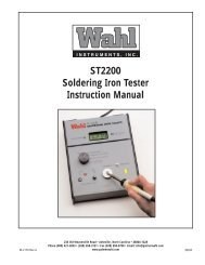
17TdggarandSwasptUodeContml<br />
In sweep mode, this key selects single or repetative sweep , trig- .*<br />
gered from front panel, or select single sweep tnggerea externally.<br />
Also can trigger single measurement internally or externally.<br />
18 Be&t Displav Function<br />
In C only function, G displays blanks and vice versa. Advantage<br />
is test speed approximately doubles.<br />
79 Measulement Range control<br />
Manual ranging may be needed during X-Y recording. Also needed<br />
using C offset capability to obtain one extra digit of C resolution.<br />
20 Measumment speed Control<br />
Fast mode requires approximately 70ms per measurement in C or<br />
G only modes and 150ms per measurement in C and G mode.<br />
Medium mode requires approximately 100ms per measurement in<br />
C or G only modes and 1 QOms per measurement in C and G mode.<br />
Slow mode requires approximately 330ms per measurement in C<br />
or G only mode and 520ms in C and G mode. (Advantage is noise<br />
rejection and in some cases 1 more digit display resolution).<br />
2 1 Add One D&it to Capacitanca Resolution<br />
Option 001 and C-offset enables one extra digit of resolution on<br />
1OOpF and InF ranges.<br />
22 select Fmm Two Test Levels<br />
Choose 30mVrms or 1OmVrms AC test level.<br />
- hJ/JTH -<br />
A % A %<br />
STORE DIGIT SHIFT<br />
X-Y RECORDER<br />
TRIGGER<br />
4<br />
ENTER<br />
23 Vettfy Normal Operation<br />
Self test does not check calibration.<br />
24 Compensate Fixture Residuals<br />
With fixture open, store residual capacitance and conductance.<br />
Residuals are compensated when CORRECTION ENABLE is turn-<br />
ed on.<br />
25 Pmtaction Fmm High Voltaga Bias.<br />
When switch is in + 42V position, shorting cap has no effect. Max<br />
output is &42V.<br />
When switch is in + 1OOV position - center pin and shield of<br />
Remote on/off connector must be shorted to turn bias on. This<br />
should be accomplished by removing shorting cap and shorting<br />
center pin to shield through remote switch.<br />
26 Test Floating or Gtvundad Devices<br />
Floating devices can be tested over <strong>4280A</strong>’s entire measurement<br />
range. Grounded devices can be tested in top two ranges only<br />
(1 OOpF/l mS and 1 nF/l OmS ranges).<br />
27 Two Ten&al Pair<br />
Hi and Low terminals have guard on coaxial shields.<br />
28 Mounting Guides for l&WA and 16081A Fixwas<br />
1608OA, 16081 A and 16082A fixtures mounts directly on <strong>4280A</strong> front<br />
panel. These guide holes accept fixture guide pins.<br />
29 Connect Circuit Ground to Chassis Ground<br />
I<br />
I<br />
9
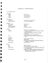
n <strong>4280A</strong> Specifications<br />
n 428OA Measurement Functions: II C-V Measurement:<br />
Capacitance (C), conductance (G), capacitance and con-<br />
ductance (C&G), capacitance vs. DC bias (C-V), conduc-<br />
tance vs. DC bias (G-V), capacitance and conductance vs.<br />
DC bias (C&G-V), capacitance vs. time (C-t), conductance<br />
vs. time (G-t) and capacitance and conductance vs. time<br />
(C&G-t).<br />
AC Test Signal:<br />
Frequency: 1 MHz + 0.01 %<br />
OSC Level: 30mVrms If: 10% or 1 OmVrms + 10 %<br />
Display: Max 4% digits (5% digits for Opt 001)<br />
Maximum Display Counts: C = 19000,<br />
G = 12000<br />
Measurement Terminals: Two-terminal pair<br />
Configuration: High and Guard, Low and Guard<br />
Max Offset Voltage: + 1mV (DC Bias OFF)<br />
Max Resistance: + 20R<br />
Max Allowable Current: + 1 OOmA<br />
Connection Mode: Set connection configuration<br />
between DUT and Measurement circuit.<br />
Connection Mode<br />
Floating Grounded<br />
Usage To measure To meawre<br />
Floated Device Grounded Device<br />
Connection<br />
To measure<br />
strays for<br />
compensation<br />
I I I I I<br />
v1 = Internal DC bias source when an external bias source<br />
(pulse generator) is used. V1 and Va can be set either from internal<br />
or external DC bias source.<br />
n C/G Measurement Range (Error Compensation Of9<br />
C/G<br />
Range<br />
Measurement Range<br />
C= IOpF C=OOO1pF to 19000pF<br />
G = 1 OOllS G = 0 OIBS to 120.00&<br />
Floating DUT Grounded DUT<br />
This C/G range IS not<br />
available<br />
mode<br />
in Grounded DUT<br />
C=lOOpF C=O.OlpF to 19O.OOpF C = 0 01 pF to 50 OOpF’<br />
G=lmS G = 0.0001 mS to 1 2000mS G = 0.0001 mS to 1 2000mS<br />
C=lnF C = 0 0001 nF to 1.9000nF C = 0 0001 nF to 1 7600nF’<br />
G = 1 OmS G = 0 001 mS to 12 OOOmS G = 0.001 mS to 1200CmS<br />
‘Typical values<br />
Measures C-V, G-V or C&G-V characteristics using inter-<br />
nal staircase bias.<br />
n C-t Measurement:<br />
Measures C-t, G-t or C&G-t characteristics using internal<br />
bias source, external pulse bias source, or combination of<br />
internal and external bias sources.<br />
Burst Mode: One pulse is applied then<br />
repetative measurements are made with specified<br />
time interval between measurements. Used when<br />
delay time setting >lOmS.<br />
Sampling Mode: Repetative pulses are applied with<br />
single samples taken between pulses. Delay be-<br />
tween application of measure voltage and sample<br />
can be specified. Used when delay time setting is<br />
less than 1Oms. This mode requires addition of an<br />
external pulse generator like <strong>HP</strong>’s 8112A.<br />
Measurement Speed vs. Oscillator Level and<br />
Display Resolution:<br />
Measurement Speed OSC Level Display Digit<br />
pgiigq<br />
W Measurement Accuracy:<br />
Measurement accuracy in the following tables is valid<br />
when these conditions are met: 1) r30-minute warm up, 2)<br />
ZERO/OPEN calibration is performed, 3) CORRECTION<br />
ENABLE IS ON, and 4) Temperature 23”C+5”C. Note that<br />
correction enable compensates for measurement residuals<br />
and reduces measurement range by the amount of residual<br />
compensation.<br />
Accuracy is valid at <strong>4280A</strong> front panel with cable length<br />
switch in “0” position. Additional error must be added<br />
when using the 16082A test cables and with cable length<br />
switch in the “lm” position. Add 0.1 % of reading for C<br />
and 0.2% of reading for G when 16082A is used.<br />
C accuracies are specified when D I 0.05 when using<br />
C&G, C&G-V and C&G-t display modes. C accuracies are<br />
specified when D 5 0.01 when using C only, G only, C-V<br />
G-V, C-t and G-t display modes. See page 10 Reference<br />
Data for more.<br />
ACCUIX~ Tab/e 1 -C&G Display Modes: Use this table in the following measurement modes: 1) C&G,<br />
2) C&G-V and 3) C&G-t when not applying external fast pulses. See tables 3 and 4 for accuracy when<br />
applying external fast pulses.<br />
DUT<br />
Connection Floating DUT Mode Grounded DUT Mode<br />
Mode<br />
Available<br />
Bias Modes<br />
*INT Bias OFF,=== 2 /or A ‘INT Bias OFF, = .q ./or A<br />
‘EXT SLOW Bias = or JL *EXT SLOW Bias = 0rJ-L<br />
*lNT+ EXT SLOW Bias ‘INT+ EXT SLOW Bias<br />
0% = 3OmVrms O!X = IOmVrms OSC = 3OmVrms ES = 1OmVrms<br />
k (0 1 % rdg + 5 cnts) t(0 2% rdg + 5 cnts)<br />
This C/G range IS not wallable in Grounded DUT mode<br />
Range - ‘”<br />
?[02% rdg+(L+& cnts] c[O3% rdg+(i+& cnts]<br />
l- 10 OPF k (0 1 % rdg + 3 cnts) f (0 2% rdg + 3 + cnts) c[O 3% rdg + 3+ cnts) +(O 4% rdg + 30 + cnts)<br />
1<br />
1<br />
1mS ?[02% rag+@+& cntsl +[03% rdg+(3+% cnts] f[04% rdg+(30+$ cnts] ?[05% rdg+(30+% cnts]<br />
lnF2 + 10 1 O/o rda + 3 cntsi k (0 2% rdq + 3 cnts) i-(0 3% rdg+ 10 cnts) +(04% rdgc 10 cnts)<br />
1<br />
1 OmS ‘[1 2% rdg+(3+% cnts] k[l 2% rdg+(3+$ Cntsl +[I 4% rdg+(lO+$J cnts] k[l 4% rdg+(20+$ cnts]<br />
1 NC = C de&y counts m C & G mode with CORRECTION ENABLE OFF<br />
6
b<br />
C/G<br />
Measuring<br />
Range<br />
Accuracy Table 2 - C only and G only Display Modes: Use this table in the following measurement<br />
modes: 1) C only, 2) G only, 3) C-V, 4) G-V, 5) C-t and 6) G-t. Do not use this table when applying external fast<br />
pulse bias. See tables 3 and 4 for fast external pulse bias accuracy.<br />
DUT<br />
Connection<br />
Mode<br />
Floating DUT Mode Grounded DUT Mode 1<br />
AvaIlable *INT Bias OFF. -Y, 2, / or A *INT Bias OFF z, 2, / 01 A<br />
Boas Modes *EXT SLOW Boas z or q<br />
*EXT SLOW Boas = 01 q<br />
‘lNT+ EXT SLOW Boas<br />
*INT + EXT SLOW Bias<br />
0% = BOmVrms OSC = IOmVrms OSC = 3OmVrms OSC = 1OmVrms<br />
1 OpF<br />
NG’<br />
~[015% rdg+(5+& cnts] &[025% rdg+(5+$) cnts]<br />
This C/G range IS not awlable I” Grounded DUT mode<br />
C/G<br />
Measuring<br />
1 oofis k [O 25% rdg + (5 +& NC’ cnis] k[O35% rdg+(5+ $$ cnts]<br />
Range<br />
1 OOpF t[O 15% rdg+@+$ cnts] +[025% rdg+(3+$ cnts] -t [0 3 0 h rdg + (40 ++ NG’ cnls] ?[04% rdg+(40+$ cnts]<br />
1mS<br />
NC’<br />
+[025% rdg+(3++ cnts] +[035% rdg+(3+ s cnls] 2 [0 4% rdg + (40 + $ cnts] ?[05% rdg+(40+$ cnts]<br />
lnF2 i-[015X ,,:,+,3+$& cnts] ?[025O/a rdg+(3+ $ cnts] i- [O 3% rdg + (20 + $) cnls]<br />
1<br />
?[04% rdg+(ZO+& cnts]<br />
1 OmS3 k[l 25% rdg+(3+$ cnts] k[l 25% rdg+(3+ & cnts] ?[l 4% rdg+(ZO +$ cnts] t[l 4% rdg+(ZO+& cnts]<br />
1 NG = G display counts I” C&G mode with CORRECTION ENABLE OFF 2 C accuracy is not specified for C display rPOOpF<br />
NC = C display counts I” C&G mode with CORRECTION ENABLE OFF 3 G accuracy IS not speded for G display r2mS<br />
Accuracy Table 3 - C&G-t Modes: Use this table in the C&G-t display mode when applying fast pulses<br />
through external fast connector.<br />
DUT<br />
Connection<br />
Mode<br />
AvaIlable<br />
Bl%<br />
Modes<br />
1OpF<br />
1 oops<br />
1 OOpF<br />
1mS<br />
1nF<br />
1 OmS<br />
1 NC = C display tour<br />
Floating DUT Mode (Note: Grounded DUT Mode not available)<br />
‘EXT FAST Bias nL<br />
‘EM FAST + INT Bias q + =<br />
‘EXl FAST + EXT SLOW Bias 2 + =<br />
OSC = 30mVrms<br />
t[(O4++/0 idg+(40+~+2T1*10-6)cnts]<br />
i;[(O5++ rdg+(40+% +T+2T1.10-6) cnts]<br />
?[(04+$)% rdg+(33+3+2T1*10-6) cnts]<br />
+[(05++ rdg+(33+$$+F+2T’*106) cnts]<br />
5 0<br />
k [(l 4 + $ /o rdg + (43 + “+ 2T’ .10~6) cnls]<br />
+[(25+$)% rdg+(43+&+?+2T’&) cnts]<br />
I” C&G-t mode with CORRECTION ENABLE OFF<br />
T IS calculated at Nth measwement paint of a C&G-f cuive T = N*delay tome fld)*106 T is in seconds<br />
OSC = 1OmVrms<br />
?[(05+$)% rdg+(40+y+2T’*10-6) cnts]<br />
5 [(O 6 + +/o rdg + (40 + ,$ + + + 2T’ ~10~~) cnts]<br />
,[(05++ rdg+(33+?+2T’&) cnts]<br />
5 0<br />
N 1<br />
+[(06+Y)/0 rdg+(33+&+900+2T1.106<br />
T’ 1 cnts]<br />
k[(l 5+$)% rdg+(43+=$+2T’*@) cnts]<br />
t[(25++ rdg+(43+% +~+2T’*10~6) cnts]<br />
Accuracy Table 4 - C-t, G-t Modes: Use this table when in the C-t or G-t display mode and applying fast<br />
pulses through external fast bias connector<br />
DUT<br />
Connection<br />
Mode<br />
Available ‘EXT FAST Bias q<br />
Bl% ‘EXT FAST + INT Bias q+-=<br />
Modes ‘EXT FAST + EXT SLOW Bias 4 +=<br />
1 OpF<br />
1 oars<br />
Floating DUT Mode (Note: Grounded DUT Mode not available)<br />
OSC = 3OmVrms<br />
OSC = IOmVrms<br />
?[(06 +$/~rdg(40 +!$+= +2T’*lO”)cnts] i[(O7+~)~/~rdg+(40+~+~+2T~~,o-~)cnts]<br />
T’ T’ T’ T’<br />
?[(07 ++ rdg(40 +F+F +2T1*106)cnts] ?[(08 ++rdg+(40+ !!$+~+2T1.10-s)~,,~~]<br />
1OOpF + [(O 6 +$o rdg +(33 +s+3= + 2T’ *, O-6) cnts]<br />
T’ T’<br />
1mS<br />
1 nF*<br />
1OmS<br />
NC’ 300<br />
*I(07 +~)n/,rdg+(33+4n+il+2T’.10~6)cnts]<br />
T’<br />
?[(l 6 +$ rdg +(43+$+3$+2T’~@)cnts]<br />
T’<br />
?[(2 7 +$o rdg + (43 +s+3+ + 2T’ *, 06) cnts]<br />
T’<br />
1 NC = G display cwnts I” C&G mode with CORRECTION ENABLE OFF<br />
NC = C display CO”“& in C&G mode wllh CORRECTION ENABLE OFF<br />
T IS calculafed at Nfh meawrement point of a Gt or Gl c”we<br />
T = N*delay time (ld)*106 T IS in seconds<br />
t[(O8 +~)%rdg+(33+~+g~+2T1-,0”)cnts<br />
T’ T’<br />
+[(08 ++/a rdg+(33+~+903+2T1*10j~CnfS]<br />
T’<br />
5 0 NG’<br />
i[(l 7 +ii) /a rdg+(43 + 30+=+2T’+cnls<br />
T’<br />
5 0 NC’ 900<br />
?[(27 +.)/o rdg+(43 + 11+,+2T’*106)cnfs<br />
7
n Math Functions:<br />
Display measured C/G values as differential values (A),<br />
% ratio (%) or differential % (A%) of the reference value.<br />
A = C-C& or G-Gref<br />
% = k x 100% or Gx 100%<br />
Gref<br />
A% = p x 100% or $$@ x 100%<br />
n Self Test:<br />
Verifies functional operation but does not calibrate.<br />
H DC Bias Source:<br />
Output Mode: OFF, -= (DC), 9, /or /k<br />
/or A : Selected when using C-V, G-V,<br />
C&G-V modes<br />
q, = or OFF: SeSecztk?o;;;n using C-t, G-t or<br />
: or OFF : Selected when using C only or G<br />
only modes.<br />
Output Resistance: 10Q<br />
Max Output Current: +6mA<br />
Output Voltage Range/Resolution/Accuracy:<br />
~1<br />
Resolution *(% of setting + volts)<br />
‘Accuracy is specified at 23°C + 5°C. Error doubles at<br />
O”G55”C<br />
Ranging: Auto ranging. Fixed range is provided in<br />
= mode when V Limit/Range hold is in use.<br />
Staircase Sweep Parameter Settings<br />
(CV Function Only):<br />
Start/Stop Voltage: Any voltage within the output<br />
voltage range.<br />
Step Voltage: Resolution of step voltage is auto-<br />
matically set as lesser of Start or Stop voltage setting.<br />
Example, if Start is 1 .OOOV and Stop is 3O.OV,<br />
resolution of Step is O.OlV.<br />
OV to 3.999V: 1mV step<br />
4.OOV to 39.99V: 1OmV step<br />
4O.OV to 2OO.OV: 1OOmV step<br />
Hold Time, Step Delay Time (th, td ):<br />
3ms - 65ms: 1 ms step<br />
0.07s - 99.99s: 1 Oms step<br />
100.0s - 650.0: 1 OOms step<br />
Hold Time/Step Delay Time Setting<br />
Accuracy: + (% of setting + seconds)<br />
Time 565ms: +[0.02% setting + (loons + bias<br />
settling time)]<br />
Time z65ms: +[0.02% setting + (0.5ms + bias<br />
settling time)]<br />
Pulse Bias Parameter Settings (C-t Function Only):<br />
DC/Pulse/Measurement Voltage: Any voltage within<br />
the output voltage range.<br />
8<br />
DC Bias Source (continued)<br />
Number of Readings Which Can Be Obtained:<br />
Burst Mode: 1 to 9999<br />
~1<br />
Sampling Mode: 1 to 5/td (td = delay time)<br />
Hold Time (th):<br />
EXT BIAS SLOW 65mS 5th C 1 S = 500~s<br />
*Maxlmum Hold Time Setting I” sampling mode is llmited as<br />
follows.<br />
Function<br />
Measuring Maximum Hold Time<br />
Speed (whichever is shorter)<br />
N = Nth measuiement point, id = delay time<br />
Delay Time (t(f):<br />
Range: 1 Ops - 32s<br />
Resolution: 10~s Z&-j 565ms: 10~s<br />
65ms 5 td 5 1 S: 500/S<br />
fsstdslos: lms<br />
tOs&d~32s: l&tlS<br />
Delay Time Range in Burst Mode:<br />
Delay Time Range in Sampling Mode:<br />
EXT BIAS SLOW: 200~ to 5s<br />
EXT BIAS FAST: lO/zs to 5s<br />
Number of C/G-t Readings which can be<br />
obtained: This determines the resolution which can<br />
be obtained.<br />
Burst Mode: 1 to 9999 readings<br />
Sample Mode: 1 to delay tir?re in seconds (readings)<br />
Hold Time/Delay Time Setting Accuracy: + (% of<br />
setting + seconds)<br />
Time 165ms: +[0.02% + (1 OOms*t + Bias Settling<br />
Time)]**<br />
Time r65ms: + [0.2% + (0.5ms + Bias Settling<br />
mime)]**<br />
*I: 10ms when internal bias is used.<br />
l 2: 1Oms to 100ms delay will be added to delay time<br />
when doing C&G-t measurements.<br />
W DC Bias Sourn: Reference Data<br />
Settling Time: 0.05 * AV + 1.7 (ms) to within 99.9%<br />
of final value. AV = voltage Swing<br />
Ranging Time: 10ms<br />
Bias Voltage Output Set/Reset Logic Processing 41<br />
Time: I 20ms<br />
Bias Voltage Setting Change Logic<br />
Processing Time ( z mode): 120ms<br />
31
n Recorder Output:<br />
Output DC voltage proportional to C/G display counts<br />
and voltage/time sweep range.<br />
Output VOltgage: + 1OV for C, G and V/t data.<br />
C or G Data: f 1OV for + 1000 counts (lOmV/count)<br />
V Data: - 1OV for Start/Stop voltage, whichever is<br />
more negative. + IOV for Start/Stop voltage, whichever<br />
is more positive. Max 1000 data points (20mV<br />
resolution).<br />
Time (t) Data: - 1OV at the application of mea-<br />
surement voltage. + 1OV at the final data point. Max<br />
1000 data points (20mV resolution).<br />
Output Voltage Accuracy: + (% of output voltage +<br />
volts)<br />
C or G = *(0.5% + 20mV)<br />
V or t = +(0.5% + 40mV)<br />
Pen Lift Output: Normally +5V. OV during C-V/t<br />
measurement.<br />
Smoothing Function: Output filter time constant can<br />
be set 0.02s or 0.2s. Initial and post delay time of 2s<br />
and 1.5s can be inserted in C-V/t basic function.<br />
Scaling Output: L.L., Zero and U.R.<br />
m Data Outpui/Remote Contmk<br />
<strong>HP</strong> - IB: Not just IEEE-488, but the hardware,<br />
documentation and support that delivers the shortest<br />
path to a measurement system.<br />
Block Mode Output: Perform C-V/t characteristics<br />
measurement and store measured data in an internal<br />
data buffer. Then, packed data can be output. In this<br />
mode, front panel display, math function and recorder<br />
output do not function. Data with/without error com-<br />
pensation can be output.<br />
Maximum Number of Data Which Can be Stored:<br />
C, G, C-V/t or G-V/t Function: 680 data points<br />
C-G, C&G-V/t Function: 400 data points<br />
n Option lull High Resolution Offset<br />
Capacitance Measurement:<br />
Increase C measurement resolutions by one digit on<br />
1 OOpfll nF ranges using capacitance offset reference. This<br />
option cannot be field installed.<br />
c Offset Range: 0 to 1023 picofarads. C offset value<br />
can be set by measured data or numeric keys.<br />
C Offset Resolution: 1 picofarad<br />
C Offset Setting Accuracy: +(0.2% of reference<br />
value + 05pF). This error can be compensated using<br />
CORRECTION ENABLE key.<br />
Measurement Accuracy: Accuracy is the sum of 1)<br />
accuracy reading before offset plus 2) accuracy of<br />
reading after offset.<br />
High Resolution C Mode ON/OFF Time: 350m<br />
Measurement Range/Resolution/Display Digit:<br />
Measuring Osc Leve, Measurement Range From Reference Value<br />
Time Range of Offset Value<br />
lOOpF/lmS<br />
lnF/lOmS<br />
FAST lOmV/30mV<br />
k 19.OOpF + 19O.OpF<br />
MED<br />
1OmV<br />
-~~<br />
30mV<br />
* 120.0@<br />
+19.OOOpF<br />
kl 200mS<br />
k19OOOpF<br />
SLOW lOmV/30mV +120.00@s -cl 2000mS<br />
n Reference Data:<br />
Reference data are given for information purposes and<br />
should not be considered specifications.<br />
n Residual Impedance of the l&.WOA:<br />
Radial Lead Contact Block: 70nH, 50mh2<br />
Axial Lead Contact Block: 90nH, 50mQ<br />
n Additional Emrs Due to Test Lead Length:<br />
When using 16081A, 16082A or P/N 8120-4195 coaxial<br />
cable up to 5m long, use below figures to estimate addi-<br />
tional error.<br />
a Test Lead<br />
e<br />
Length (m)<br />
51<br />
m<br />
2<br />
b<br />
zi<br />
z 0.1<br />
.g<br />
B<br />
2<br />
0 0.01<br />
1<br />
1OP loop Ill<br />
lOOr lm 10m<br />
8 Emr Compensation:<br />
Cable Length Compensation: Om, lm or 0-5m.<br />
Residuals of standard cable (<strong>HP</strong> P/N 8120-4195) up to 5<br />
meters long can be internally compensated.<br />
Zero Open: Internally compensate stray capacitance<br />
and conductance of test fixture with fixture open.<br />
Additional L-R Compensation: Compensate residuals<br />
not included above using external computer.<br />
Measurement Conditions:<br />
Connection Mode: Grounded for compensation<br />
Test Signal Level: 30mVrms<br />
Compensation Range: L-R data will be displayed as<br />
L (in C display) and R (in G display).<br />
L: 19.000/4H<br />
R: 190.009<br />
Compensation Accuracy = -+(% rdg + counts):<br />
L: f [0.5% rdg + (20 +$$) counts]<br />
R: *[1.2% rdg + (lo+ &$-) counts]<br />
1NR = resistance display counts<br />
NL = inductance display counts<br />
C(F)
Reference Data: (Continued)<br />
l C/G Measurement Time:<br />
Total Measurement Time is the sum of 1) Net Measure-<br />
ment Time, 2) Internal Error Compensation Time, 3) Math<br />
Function Time, and 4) Display Time.<br />
The table below shows Total Measurement Time in<br />
milliseconds. Net Measurement Time is shown in<br />
parentheses.<br />
Ranging Time: 10Oms<br />
OSC Level Changing Time: 40ms<br />
Connection Mode Changing Time: 11 Oms<br />
Initial Setting Time: 650ms<br />
Time Constant of C/G Measurement Circuit:<br />
50~s when measurement time interval is l: Multiply G measurement error*(l + Q2)<br />
n Genera/ Specifications<br />
W Operating Temperature:<br />
0°C - 55°C and Relative Humidity 190% at 40°C<br />
n Power Requirement:<br />
1 OOV, 12OV, 220V rlr 10 O/o, 240V + 5% - 10% , 48 - 66H2,<br />
max 140VA<br />
n Dimensions:<br />
426mm (W) x 177mm (H) x 499mm (D) or 16.7” (W)<br />
x 7.0” (H) x 19.7” (D)<br />
n Weight;<br />
Approximately 15.6kg or 34.3 Ibs.<br />
n Ordering lnforma tion<br />
n Standard Instrument:<br />
<strong>4280A</strong> IMHz C <strong>Meter</strong>/C-V <strong>Plotter</strong>. . . . . . . . .<br />
moptions:<br />
Opt. WI: High Resolution Offset Capacitance<br />
Measurement increases C Resolution<br />
by 1 digit on lOOpFl1 nF Ranges.<br />
Cannot be field installed.<br />
Opt. 907: Front Handle Kit<br />
(<strong>HP</strong> P/N 5061-0090)<br />
Opt. 908: Rack Flange Kit<br />
(<strong>HP</strong> P/N 5061-0078)<br />
Opt 909: Rack Flange & Front Handle Kit<br />
(<strong>HP</strong> P/N 5061-0084)<br />
Opt 910: Extra Manual<br />
(<strong>HP</strong> P/N 04280-90000)<br />
n Accessories:<br />
16D58A: Test Fixture for Packaged Semicon-<br />
ductor Testing<br />
1609OA: Test Fixture (furnished with <strong>4280A</strong>)<br />
1609lA: Test Leads, 2 <strong>Meter</strong>, Double Shielded.<br />
16092A1 Test Leads, 1 <strong>Meter</strong>, Single Shielded.<br />
16083A: Pulse Bias Noise Clipper (for use with<br />
external Pulse Generator)<br />
<strong>HP</strong> P/N 12!50-0929: Remote ON/OFF Shorting Cap<br />
(furnished with <strong>4280A</strong>)<br />
For more information, call your local <strong>HP</strong> Sales Office or nearest Regional Office: l Eastern (201) 265-5000; l Midwestern (312) 2559600; l Southern (404) 9551500; l Western<br />
(213) 9707500; l Canadian (416) 676.9430. Ask the operator for instrument sales. Or write Hewlett-Packard, 1601 Page Mill Road, Palo Alto, CA 94304. In Europe: Hewlett-Packard<br />
.%A., 7, rue du Bois-du-&in, P.O. Box, CH 1217 Meyrin 2, Geneva, Switzerland. In Japan: Yokogawa-Hewlett-Packard Ltd., 29-21, Takaido-Higashi Scheme. Suginami-ku, Tokyo 168.<br />
Printed in USA Data Subject To Change 5953-6949