PhD thesis Alessandro Re - Università degli Studi di Torino
PhD thesis Alessandro Re - Università degli Studi di Torino
PhD thesis Alessandro Re - Università degli Studi di Torino

Create successful ePaper yourself
Turn your PDF publications into a flip-book with our unique Google optimized e-Paper software.
<strong>Università</strong> <strong>degli</strong> <strong>Stu<strong>di</strong></strong> <strong>di</strong> <strong>Torino</strong><br />
Dipartimento <strong>di</strong> Fisica Sperimentale<br />
Scuola <strong>di</strong> Dottorato in Scienza e Alta Tecnologia<br />
Ciclo XXIII<br />
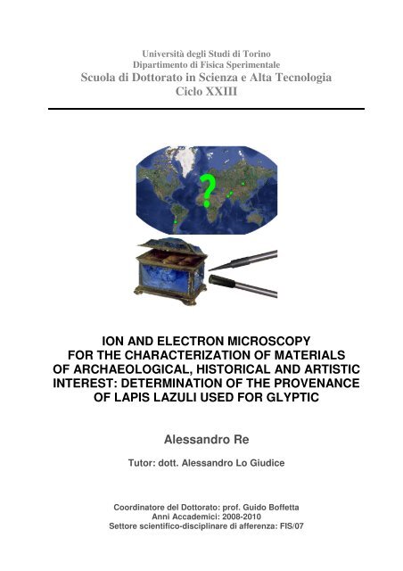
ION AND ELECTRON MICROSCOPY<br />
FOR THE CHARACTERIZATION OF MATERIALS<br />
OF ARCHAEOLOGICAL, HISTORICAL AND ARTISTIC<br />
INTEREST: DETERMINATION OF THE PROVENANCE<br />
OF LAPIS LAZULI USED FOR GLYPTIC<br />
<strong>Alessandro</strong> <strong>Re</strong><br />
Tutor: dott. <strong>Alessandro</strong> Lo Giu<strong>di</strong>ce<br />
Coor<strong>di</strong>natore del Dottorato: prof. Guido Boffetta<br />
Anni Accademici: 2008-2010<br />
Settore scientifico-<strong>di</strong>sciplinare <strong>di</strong> afferenza: FIS/07
<strong>Università</strong> <strong>degli</strong> <strong>Stu<strong>di</strong></strong> <strong>di</strong> <strong>Torino</strong><br />
Scuola <strong>di</strong> Dottorato in Scienza e Alta Tecnologia<br />
Tesi <strong>di</strong> Dottorato <strong>di</strong> Ricerca in Scienza e Alta Tecnologia<br />
In<strong>di</strong>rizzo: Fisica e Astrofisica<br />
ION AND ELECTRON MICROSCOPY<br />
FOR THE CHARACTERIZATION<br />
OF MATERIALS OF ARCHAEOLOGICAL,<br />
HISTORICAL AND ARTISTIC INTEREST:<br />
DETERMINATION OF THE PROVENANCE OF<br />
LAPIS LAZULI USED FOR GLYPTIC<br />
<strong>Alessandro</strong> <strong>Re</strong><br />
Tutor: Dott. <strong>Alessandro</strong> Lo Giu<strong>di</strong>ce<br />
XXIII Ciclo, Marzo 2011
[…] Then Gilgamesh issued a proclamation through the land, he<br />
summoned them all, the coppersmiths, the goldsmiths, the stone-workers,<br />
and commanded them, "Make a statue of my friend". The statue was<br />
fashioned with a great weight of lapis lazuli for the breast and of gold for<br />
the body. A table of hard-wood was set out, and on it a bowl of carnelian<br />
filled with honey, and a bowl of lapis lazuli filled with butter. These he<br />
exposed and offered to the Sun; and weeping he went away. […]<br />
The Epic Of Gilgamesh – “Ishtar and Gilgamesh, and the death of Enkidu”
TABLE OF CONTENTS<br />
Table of contents<br />
INTRODUCTION ......................................................................................................... 1<br />
THE HISTORICAL PROBLEM ....................................................................................... 3<br />
THE USES OF LAPIS LAZULI ................................................................................................... 3<br />
THE QUARRIES OF LAPIS LAZULI ............................................................................................. 5<br />
Badakhshan, Afghanistan............................................................................................. 6<br />
Pamir Mountains, Tajikistan ......................................................................................... 6<br />
Chagai Hills, Pakistan .................................................................................................. 7<br />
Lake Baikal, Siberia ..................................................................................................... 7<br />
Chile, Coquimbo region................................................................................................ 7<br />
Other quarries ............................................................................................................ 8<br />
PETROGRAPHY OF LAPIS LAZULI............................................................................... 9<br />
LAZURITE......................................................................................................................... 9<br />
DIOPSIDE ...................................................................................................................... 10<br />
OTHER MINERALOGICAL PHASES........................................................................................... 11<br />
THE SAMPLES ........................................................................................................... 16<br />
ROCKS .......................................................................................................................... 16<br />
Sample preparation ................................................................................................... 16<br />
ARTWORKS OF THE “COLLEZIONE MEDICEA DI PIETRE LAVORATE” ................................................ 18<br />
I
Table of contents<br />
ANALYTICAL TECHNIQUES ....................................................................................... 20<br />
II<br />
ION BEAM ANALYSIS ......................................................................................................... 21<br />
PIXE: Particle Induced X-ray Emission ......................................................................... 22<br />
IL: Ionoluminescence ................................................................................................ 24<br />
ELECTRON PROBE ANALYSIS................................................................................................ 26<br />
EPMA: Electron Probe Micro-Analysis........................................................................... 28<br />
CL: Cathodoluminescence .......................................................................................... 28<br />
RS: RAMAN SPECTROSCOPY................................................................................................ 29<br />
THE PREVIOUS PROVENANCE STUDIES ................................................................... 30<br />
EXPERIMENTAL SETUP ............................................................................................. 35<br />
ION BEAM MICROPROBE FACILITIES ...................................................................................... 35<br />
LNL (Legnaro)........................................................................................................... 35<br />
µ-PIXE set-up at LNL.............................................................................................. 36<br />
LABEC (Firenze) ........................................................................................................ 37<br />
µ-PIXE set-ups at LABEC ........................................................................................ 38<br />
µ-IL set-up at LABEC.............................................................................................. 39<br />
Defocused-IBIL setup at LABEC .................................................................................. 41<br />
ELECTRON PROBE INSTRUMENTS .......................................................................................... 42<br />
cold-CL..................................................................................................................... 42<br />
SEM-EDX .................................................................................................................. 43<br />
SEM-CL..................................................................................................................... 44<br />
SIMULATIONS.................................................................................................................. 46<br />
µ-RAMAN SPECTROSCOPY ................................................................................................... 48
Table of contents<br />
RESULTS ON ROCKS ................................................................................................. 49<br />
PRELIMINARY CHARACTERISATION ........................................................................................ 49<br />
LAZURITE....................................................................................................................... 55<br />
DIOPSIDE ...................................................................................................................... 59<br />
OTHER PHASES................................................................................................................ 63<br />
Wollastonite.............................................................................................................. 63<br />
Calcite...................................................................................................................... 64<br />
Phlogopite ................................................................................................................ 65<br />
K-feldspar................................................................................................................. 65<br />
Phase of the cancrinite group..................................................................................... 66<br />
Phase rich in titanium ................................................................................................ 68<br />
MARKERS....................................................................................................................... 70<br />
CHECK ON A SAMPLE OF UNKNOWN PROVENANCE...................................................................... 71<br />
RESULTS ON ARTWORKS.......................................................................................... 72<br />
EXPERIMENTAL PROCEDURE ................................................................................................ 72<br />
RESULTS........................................................................................................................ 73<br />
Oval bowl (13682)..................................................................................................... 74<br />
Small case (13684).................................................................................................... 76<br />
Saltcellar (13687)...................................................................................................... 76<br />
Oval panel (13688).................................................................................................... 76<br />
Summary.................................................................................................................. 77<br />
CONCLUSION............................................................................................................ 78<br />
BIBLIOGRAPHY ........................................................................................................ 80<br />
III
INTRODUCTION<br />
Introduction<br />
Ion and electron microscopy are widely used to characterize materials in many fields.<br />
The study of samples of archaeological, historical and artistic interest is a case in which these<br />
techniques are of extreme importance. In particular Ion Beam Analysis techniques are of great<br />
interest in the Cultural Heritage field for many reasons: they do not require any sample<br />
preparation, they can be performed in air and they do not damage the sample at low ion<br />
fluences.<br />
An interesting material to be analyzed by means of Ion Beam Analysis is lapis lazuli; it is<br />
a semi-precious blue stone widely used for <strong>di</strong>fferent purposes since the antiquity but, at<br />
present, there are still some lacking information about both its trade in ancient times and the<br />
quarries exploited from <strong>di</strong>fferent civilizations. Although the Badakhshan mines in Afghanistan<br />
(the most famous being Sar-e-Sang) are widely considered as now as the only sources of lapis<br />
lazuli in ancient times, other sources have been taken in consideration, even if a systematic and<br />
exhaustive provenance study of the raw material utilized in works of art is still lacking.<br />
To contribute in the solving of the lapis lazuli provenance problem we started a<br />
systematic study of this fascinating stone comparing physico-chemical properties of rocks and<br />
historical objects. Since often it is impossible to take a sample from the object under analysis<br />
due of its extreme value, it is fundamental to use only non-destructive techniques. Nowadays<br />
there are many instruments that permits not to damage the sample under analysis and among<br />
these we concentrate our efforts on Ion Beam Analysis, to identify the provenance of lapis lazuli<br />
only by means of them. We often used also destructive techniques, like Electron Microscopy,<br />
just to speed up the characterization of geological samples and to gain experience with the<br />
material, but these techniques are not necessary for the study of precious objects.<br />
With these bases we started to go deeper in the problem surveying all the bibliography<br />
about this stone, its characteristics and the stu<strong>di</strong>es done on it, both from the historical,<br />
geological, geochemical and archaeometrical points of view. As we will see, a lot of people<br />
already worked on lapis lazuli, but up to now nobody performed an exhaustive provenance<br />
study in a non destructive way.<br />
This work rose from the Solid State Physics group of the Experimental Physics<br />
Department of the University of <strong>Torino</strong> and is part of a wide experiment of the Italian National<br />
Institute of Nuclear Physics (INFN) called FARE (External Rarefied Beams) continuation of the<br />
experiment DANTE (Developments in Analytical Nuclear TEchniques). One of the main goals of<br />
1
Introduction<br />
these experiments is to develop, install and test new apparatuses (among which a<br />
Ionoluminescence device) on the external microbeam line at the LABEC in Firenze, an INFN<br />
laboratory mainly devoted to non-destructive analyses in the field of Cultural Heritage.<br />
2<br />
In this work we were lucky to have the support and the interest of the “Museo <strong>di</strong> Storia<br />
Naturale <strong>di</strong> Firenze” in studying its collections and in particular the section “Mineralogy and<br />
Lithology” very rich in lapis lazuli, featuring both precious objects of the “Collezione Me<strong>di</strong>cea”<br />
(16 th -17 th century) and rocks of various certain provenance. Besides the “Collezione Me<strong>di</strong>cea”<br />
this study can be extended to archaeological fin<strong>di</strong>ngs to try to reconstruct the old trade-routes<br />
between ancient populations that already used this material.<br />
Going into the structure of this work, the first chapter is about the historical problem<br />
and the open questions about the origin and the provenance of lapis lazuli; in particular we will<br />
focus on the uses of this stone and the main quarries in the world. In the second chapter we<br />
present a short mineralogical contextualization of the material, while the third one contains a<br />
short description of the samples available for this provenance study and how they have been<br />
treated to speed up the measurements. The fourth chapter details the analytical techniques<br />
employed in this work and in the previous provenance stu<strong>di</strong>es of lapis lazuli, while the results<br />
obtained using them are presented in the fifth chapter. The sixth chapter describes the<br />
instruments optimized for this work while in the seventh one the approach we used to face the<br />
problem is presented, trying to find some markers to identify the <strong>di</strong>fferent provenances. In the<br />
same chapter there are also the details of the experimental results we obtained and some tests<br />
we performed to check if our method works with samples of unknown provenance. The eighth<br />
chapter shows the results obtained on the artworks of the “Collezione Me<strong>di</strong>cea”, while in the<br />
last chapter I’ll try to summarize the results obtained in this work, conclu<strong>di</strong>ng with some<br />
proposals for future improvements and how to continue with this intriguing work.<br />
Most of the results presented in this work have already been published in two papers<br />
[Lo Giu<strong>di</strong>ce et al, 2009; <strong>Re</strong> et al, 2011] and have been presented at national and international<br />
conferences; among these there are TECHNART 2009 (Athens, Greece), ICNMTA 2010 (Leipzig,<br />
Germany), SEM2010 (London, UK) and in the near future it will be presented at TECHNART<br />
2011 (Berlin, Germany).
THE HISTORICAL PROBLEM<br />
The historical problem<br />
Semi-precious stones were used since Neolithic Age for the manufacture of jewels,<br />
objects of social prestige and veneration objects. The few fragments of Sumer cuneiform script,<br />
survived till now through clay tablets, exalts not only the beauty of the semi-precious stones<br />
but also their meaning in the connections between the people and the <strong>di</strong>vinity [Bulgarelli and<br />
Tosi, 1977]. Some of these stones are very rare, because they can be found in very few places<br />
on the Earth, and so they were procured through complex networks of exchanges and trades<br />
routes and transported thousands kilometres away from their origin. This has been proved by<br />
archaeological fin<strong>di</strong>ngs, mostly coming from rich graves, among which there were also many<br />
lapis lazuli, one of the first semi-precious stones used in Middle East, Asia and Europe. In next<br />
paragraph there is a brief description of the <strong>di</strong>fferent use of lapis lazuli by <strong>di</strong>fferent civilizations<br />
in <strong>di</strong>fferent periods. In any case, the rarity and the importance of the lapis lazuli in the culture<br />
of civilization is confirmed by two <strong>di</strong>scoveries. The first consisting in a systematically reuse, as<br />
can be observed in the progressive decrease in the average size of lapis lazuli cylinder seals in<br />
the third millennium B.C. [Bussers, 1984; Collon, 1986] and their reuse as beads [Herrmann,<br />
1968]. The second consisting in glass imitation (“lapis lazuli from the kiln”) of the genuine stone<br />
(“lapis lazuli from the mountain”) that begins to appear in the second half of the second<br />
millennium B.C. [Moorey, 1994].<br />
The uses of lapis lazuli<br />
In Mesopotamia the earliest archaeological evidence of lapis lazuli’s use was traced back<br />
to the 5 th millennium B.C. [Von Rosen, 1990] with the <strong>di</strong>scovery of beads at a cemetery outside<br />
the temple walls of Eridu (Sumer) in southern Babylonia. Artistic works containing lapis lazuli<br />
used between 2700 and 2500 B.C. were recovered in the 1920’s during excavations of the<br />
ancient Chaldean city of Ur. The most famous of these were recovered from the royal tomb of<br />
Queen Pu-abi (2500 BC), inclu<strong>di</strong>ng three gold headdresses, and two bead necklaces [Sofianides<br />
and Harlow, 1990; Sutherland, 1991], as well as two statues of male goats with shoulders, eyes<br />
and horns of lapis lazuli [Coenraads and Canut de Bon, 2000]. There were many other<br />
applications of lapis lazuli, some of them <strong>di</strong>scovered only in recent periods: small objects (such<br />
as seals, amulets and jewels), larger objects (such as vessels, votive cylinders, dagger handles,<br />
etc.) and fragments of inlays are just some examples [Herrmann and Moorey, 1983; Moorey,<br />
1994].<br />
3
The historical problem<br />
4<br />
In Egypt, prior to 3100 B.C., lapis lazuli was used for scarabs, pendants, beads and<br />
inlaid jewels [Sofianides and Harlow, 1990]. The tombs of Ramses II (about 1279 B.C.) and<br />
Tutankhamon (1361-1352 B.C.) revealed rings and other jewels made of lapis lazuli. In fact, the<br />
golden mask over the head and shoulders of Tutankhamon’s mummy has eyebrows and areas<br />
around the eyes that are inlaid with lapis lazuli [Silverman, 1978].<br />
Also in Asia lapis lazuli was known and used since long time: the Indus Valley Civilization<br />
used it together with other stones to manufacture beads from the 3300 B.C., as proved by<br />
some fin<strong>di</strong>ngs in the archaeological sites of Harappa, Pakistan [Kenoyer, 1997].<br />
In China the use of lapis lazuli was mentioned the first time in Chinese annuals of the 6 th<br />
and 8 th centuries B.C., as the stone was a favourite of Chinese carvers [Bowersox and<br />
Chamberlin, 1995]. Some Chinese hair and belt ornaments carved from lapis lazuli have been<br />
dated to 551-479 B.C. [Sofianides and Harlow, 1990].<br />
In Europe, from the eleventh century A.D. [Herrmann and Moorey, 1983] until last<br />
centuries, lapis lazuli was crushed to be used as a blue pigment called “ultramarine”. During the<br />
<strong>Re</strong>naissance, lapis lazuli, was used for cups, bowls and ums, and was inlaid into clock faces and<br />
tables. An example of application of lapis lazuli it is visible in Italy with the popular flowers, bird<br />
and butterfly mosaics of Florence [Hinks, 1975]. More recently, at the beginning of 20 th century,<br />
French jewellery and artist Peter Carl Fabergè (1846-1920 A.D.) used lapis lazuli in many of his<br />
major works. Among these was one of his 58 Imperia Easter Eggs, a gift from Czar Nicholas II<br />
of Russia to Czarina Alexandria in 1912 [Coenraads and Canut de Bon, 2000].<br />
In Russia, lapis lazuli was used as a decorative stone, as at the Winter Palace in St.<br />
Petersburg and the Palace of Catherine the Great in the city Pushkin [Bauer, 1904].<br />
In more recent times, during the 20 th century, lapis lazuli were used also in North and<br />
South America primarily for local ornamental use. In South America, there have been several<br />
recent references to the use of lapis lazuli by the Moche (800-100 B.C.) and the Inca (1100-<br />
1537 A.D.) cultures, which occupied present day Peru, Ecuador, Bolivia, Northern Chile and<br />
north-western Argentina [Sofianides and Harlow, 1990] but the Columbian artefacts stu<strong>di</strong>ed at<br />
the University of La Serena have been found to contain sodalite or other blue minerals, but not<br />
lapis lazuli [Canut de Bon, 1991]. However, evidences of ancient human activity near the lapis<br />
lazuli mining area suggest that the deposit could have been known to early inhabitants of the<br />
region, but further research is needed to determine if the Chilean deposit was worked in ancient<br />
time [Rivano, 1975; Rivano and Sepúlveda, 1991].
The quarries of lapis lazuli<br />
The historical problem<br />
Only few sources of Lapis Lazuli exist in the world due to the low probability of<br />
geological con<strong>di</strong>tions in which it can form (Figure 1) [Voskoboinikova, 1938; Wyart et al, 1981],<br />
so that the possibility to associate the raw material to man-made objects is helpful to<br />
reconstruct trade routes. Historical sources were in very inaccessible places, such as Afghan<br />
and Pamir Mountains, and stones were transported for thousand of kilometres, in times for<br />
which the knowledge of trade routes is still largely incomplete. This is especially true for ancient<br />
contexts where there is an absence or scarceness of written evidences [Tosi, 1974]. Although<br />
the Badakhshan mines in Afghanistan (the most famous being Sar-e-Sang) are widely<br />
considered till now as the only sources of the Lapis Lazuli in ancient times [Herrmann, 1968;<br />
Sariani<strong>di</strong>, 1971; Tosi, 1974; Bulgarelli and Tosi, 1977; Herrmann and Moorey, 1983], other<br />
sources have been considered: Tajikistan (Lyadzhuar Dara, Pamir Mountains), Pakistan (Chagai<br />
Hills), Siberia (Irkutsk, near Lake Baikal), Iran [Herrmann, 1968] and Egypt (Sinai) [Nibbi,<br />
1981]. The last two possibilities are not geologically confirmed and their interpretations are still<br />
debated [Herrmann and Moorey, 1983; Von Rosen, 1988; Delmas and Casanova, 1990;<br />
Nicholson and Shaw, 2000], so that the provenance of ancient lapis lazuli is still an open<br />
question. Other sources [Le Strange, 1919] are: Mazanderan (but there are many doubts about<br />
it and it seem quite unlikely [Herrmann, 1968]), Dizmar in Azerbaijan and Kerman (there are<br />
doubts about the presence of metamorphic rocks and there are no evidences of lapis lazuli<br />
[Herrmann, 1968; Bowersox and Chamberlin, 1995]). Moreover there are references to other<br />
Figure 1. Map of the geological occurrences of lapis lazuli in the world<br />
5
The historical problem<br />
sources [Von Rosen, 1988], in particular to northern China and Tibet, but neither in this case<br />
there are any geological confirmation.<br />
Badakhshan, Afghanistan<br />
6<br />
Badakhshan, in north-eastern Afghanistan, has been considered for long time the only<br />
historical source for the ancient Near East and is now considered as one of the principal<br />
sources. It is located at 2400 km from Mesopotamia in an inhospitable country of bare<br />
mountain and deep ravine. There are today four known mines in the Kerano-Munjan valley<br />
located at Chimlak, Shaga-Darra-i-Robat-i-Paskaran, Stromby and Sar-e-Sang, at altitudes<br />
ranging from 2000 to 5500 m. Of the four, the latter is the only one worked today.<br />
At Sar-e-Sang the materials required for the formation of lapis lazuli must have been<br />
deposited with the original limestone. The lapis lazuli occurs in a thick, rather ill-defined band<br />
varying considerably in the concentration of lazurite and the number of accessory minerals.<br />
The specimens of lapis lazuli collected at Sar-e-Sang cover a wide range of colours from<br />
a deep violet-blue through the royal blue of the gem quality to a light blue, a turquoise and<br />
finally, a few pieces of brilliant green. The finest quality should be a pure royal blue without<br />
blemish: impurities often present include iron pyrites, calcite and dark smudges [Herrmann,<br />
1968].<br />
One of the first explorer of this region reported the method to extract the lapis lazuli<br />
[Wood, 1841]: for mining camelthorn and tamarisk twigs were used, collected from the valley<br />
below and carried up the steep path to the mind. When sufficient fuel had been collected, it<br />
was piled against the rock face and a fire was lit. When the rock was hot, cold water, which<br />
also had to be carried up the 350 m ascent, was thrown onto it. The rock cracked and split,<br />
enabling further work to be done with the primitive tools available (pick, hammer and chisel) to<br />
extract the lapis lazuli from its marble host rock.<br />
Many other authors stu<strong>di</strong>ed and cited this quarry from many point of view [Tosi and<br />
Piperno, 1973; Tosi, 1974; Bulgarelli and Tosi, 1977; Wyart et al, 1981; Majidzadeh 1982;<br />
Herrmann and Moorey, 1983; Yurgenson and Sukharev, 1985; Grew, 1988; Von Rosen, 1988;<br />
Delmas and Casanova, 1990; Moorey, 1994; Faryad, 1999; Faryad, 2002].<br />
Pamir Mountains, Tajikistan<br />
Another source that could have been exploited in ancient time is in Pamir Mountains, on<br />
the Liadjuar-Dara (“River of Lazurite”) at an altitude of 5000 m. Legend had recorded a deposit<br />
of lapis lazuli high in the Pamir range and this source was authenticated in 1930 when it was<br />
located by a Russian expe<strong>di</strong>tion. They found the route extremely <strong>di</strong>fficult and had to leave their<br />
horses at 3500 m, climbing the remaining 1500 m. The lapis lazuli occurred in a steep wall of
The historical problem<br />
marble and gneiss, at the border of an immense glacier. In this white marble there are veins<br />
and lenses of lapis lazuli, some bright-blue, some delicately blue with beautiful passages into<br />
violet and green tints [Herrmann, 1968; Webster, 1975]. Pamir lapis lazuli results to have the<br />
same quality as those from Badakhshan [Goldstein, 1981; Delmas and Casanova, 1990]. Also<br />
other authors cite this quarry [Tosi, 1974; Hogarth and Griffin, 1978; Herrmann and Moorey,<br />
1983; Von Rosen, 1988; Casanova, 1992; Moorey, 1994].<br />
Chagai Hills, Pakistan<br />
Some deposits are reported in the Chagai Hills which are located in Pakistan at the<br />
northwest boundary with Afghanistan, between the Quetta <strong>di</strong>strict and the Iranian border.<br />
However, their existence is not recognized in the literature, probably because they are not<br />
subject to geological stu<strong>di</strong>es similar to those undertaken in Afghanistan. These deposits are<br />
very near to Shahr-i Sokhta from where several objects and cutting remain have been<br />
<strong>di</strong>scovered. Chagai Hills lapis lazuli are reported to have the same quality as those from<br />
Badakhshan [Delmas and Casanova, 1990]. Other authors cite this quarry [Berthoud et al,<br />
1982; Jarrige, 1988; Tosi and Vidale, 1990; Casanova, 1992; Ballirano and Maras, 2006].<br />
Lake Baikal, Siberia<br />
The Baikal source of lapis lazuli is the most <strong>di</strong>stant from Mesopotamia, lying some 4800<br />
km away. It is situated in the valley of the River Sljudjanka at the southwest end of Lake Baikal.<br />
The Malaja Bystraja deposits are situated on the right slope of the valley of the River Lazur<br />
where its outlet runs into the River Malaja Bystraja a southern tributary of the River Irkut,<br />
which is about 22 km from the Sljudjanka deposits [Korzinskij, 1947]. There are <strong>di</strong>fferent<br />
qualities of the stone attributed to this source: poor quality and "grainy" in texture [Herrmann,<br />
1968], but also fine quality [Hogarth, 1970]. Other authors stu<strong>di</strong>ed and cited this quarry [Tosi,<br />
1974; Webster, 1975; Hogarth and Griffin, 1976; Ivanov, 1976; Ivanov et al, 1976; Herrmann<br />
and Moorey, 1983, Von Rosen, 1988; Delmas and Casanova, 1990; Moorey, 1994].<br />
Chile, Coquimbo region<br />
This quarry has been taken into account in this work because of its possible use during<br />
ancient time in the American continent. Even if the first reference to Chilean lapis lazuli in<br />
“recent times” dates back to the 19 th century [Field, 1850], there are some hypo<strong>thesis</strong> that<br />
suggest the use of Chilean lapis lazuli before the 19 th century; this question has to be<br />
investigated in future researches [Coenraads and Canut de Bon, 2000].<br />
The only known source of lapis lazuli in Chile lies in the Coquimbo <strong>Re</strong>gion, near Ovalle,<br />
in the Andes Mountains at an altitude of 3500 m. Although reference is sometimes made to<br />
7
The historical problem<br />
another Chilean deposit at Vicuña Mackenna Mountain near Antofagasta [Webster, 1975;<br />
Sofianides and Harlow, 1990] but this material has been identified as dumortierite [Canut de<br />
Bon, 1991]. Once considered a minor or unimportant locality, with the lapis lazuli described as<br />
“at best me<strong>di</strong>ocre” [Wyart et al, 1981], the Chilean deposit has produced significant quantities<br />
of attractive material in recent years. Today, Chilean lapis lazuli is exported as raw material, or<br />
incorporated into jewelry, carvings and decorative buil<strong>di</strong>ng materials by local artisans<br />
[Coenraads and Canut de Bon, 2000]. Other authors stu<strong>di</strong>ed this quarry [Bruggen 1921; Tosi,<br />
1974; Hogarth and Griffin, 1976; Cuitiño, 1986; Moorey, 1994; Corona Esquivel and Benavides<br />
Muñoz, 2005].<br />
Other quarries<br />
8<br />
There are also other quarries mentioned but not very used because they produce some<br />
poor quality lapis or find out in lands far from Ancient East or exploited only in recent periods.<br />
Here is just a list of the places and some of the authors that cited them:<br />
- Russia (Ural Mountains) [Zöldföl<strong>di</strong> and Kasztovszky, 2003];<br />
- Myanmar or Burma (Mogok region) [Webster, 1975; Hogarth and Griffin, 1976; Von<br />
Rosen, 1988; Moorey, 1994];<br />
- Italy (Latium) [Hogarth and Griffin, 1975; Hogarth and Griffin, 1976; Von Rosen,<br />
1988];<br />
- Angola (Dattawa Valley) [Webster, 1975; Von Rosen, 1988];<br />
- North Africa (Atlas Mountains) [Kulke, 1976; Von Rosen, 1988];<br />
- California (Cascade Canyon) [Rogers, 1938; Webster, 1975; Hogarth and Griffin, 1976;<br />
Moorey, 1994];<br />
- Colorado/Wyoming/Utah (Italian Mountain and Green River) [Bradley, 1964; Webster,<br />
1975; Hogarth and Griffin, 1976; Hogarth and Griffin, 1980; Von Rosen, 1988;<br />
Moorey, 1994];<br />
- N.Y. State (Edwards) [Jensen, 1976];<br />
- Canada (Baffin Island) [Webster, 1975; Kulke, 1976; Hogarth and Griffin, 1976;<br />
Hogarth and Griffin, 1978; Von Rosen, 1988];<br />
- Cuba [Tosi, 1974];<br />
- Brazil [Tosi, 1974].
PETROGRAPHY OF LAPIS LAZULI<br />
Petrography of lapis lazuli<br />
Lapis lazuli is a metamorphic rock characterized by the presence of the mineral lazurite,<br />
combined with other types of minerals whose presence and relative amount varies from and<br />
within deposits. The typical blue colour of the rock is due to the mineral lazurite, that seldom<br />
presents well-formed crystals, since usually is an aggregate of quite small crystals. Lazurite is<br />
traversed by gray-white or yellowish veins, due to the presence of various accessory minerals<br />
such as calcite, wollastonite, phlogopite, plagioclase, <strong>di</strong>opside and others. There may be also<br />
other feldspathoids of the same lazurite family such as haüyne, sodalite or nosean.<br />
Furthermore, lapis lazuli of all deposits contain small inclusions of pyrite, mistaken in the past<br />
for golden inclusions.<br />
The first attempts to classify the lapis lazuli from a mineralogical point of view have<br />
been done in the 18 th century [Sage, 1777; Buffon, 1787] but there were still a lot of confusion<br />
between the rock lapis lazuli and the mineral lazurite, often mistaken. Only at the end of the<br />
19 th century there were the first scientific characterization [Brögger and Bäckström, 1891], with<br />
the analysis of the lazurite separated by all the other minerals.<br />
Also the metamorphic con<strong>di</strong>tions of the formation of lapis lazuli have been investigated<br />
in a lot of works, usually together with the mineralogical characterization of the rock; most of<br />
them are focused mainly on the deposit sited in Afghanistan [Blaise and Cesbron, 1966;<br />
Schreyer and Abraham, 1976; Wyart et al, 1981; Yurgenson and Sukharev, 1985; Grew, 1988;<br />
Faryad, 1999; Faryad, 2002], in Siberia [Ivanov, 1976; Ivanov et al, 1976], in Chile [Cuitiño,<br />
1986; Corona Esquivel and Benavides Muñoz, 2005], in Canada [Hogarth and Griffin, 1978] and<br />
in Colorado [Hogarth and Griffin, 1980], but more recent works try to compare the genesis of<br />
<strong>di</strong>fferent deposits [Aleksandrov and Senin, 2006; Dill, 2010].<br />
Due to the heterogeneity of lapis lazuli is convenient to analyse the single phases to find<br />
some marker useful for a provenance study. For this reason this work is mainly focused on two<br />
mineral phases, i.e. the main phase lazurite and the accessory phase <strong>di</strong>opside that is present in<br />
all the samples of the three Asian provenances under investigation.<br />
Lazurite<br />
Lazurite is a tectosilicate belonging to the feldspathoids family; more specifically, it<br />
belongs to the sodalite group. This group consists of eight minerals, among which the main<br />
ones are: sodalite (Na8Al6Si6O24Cl2), nosean (Na8Al6Si6O24(SO4)), haüyne ((Na,Ca)4-8Al6Si6(O,S)24<br />
9
Petrography of lapis lazuli<br />
(SO4,Cl)1-2) and lazurite (Na6Ca2Al6Si6O24[(SO4),S,Cl,(OH)]2) [Anthony et al, 2001], even if there<br />
is a tendency to consider the lazurite as a variety of haüyne rich in sulphur [Rogers, 1938; Van<br />
Peteghem and Burley, 1963] rather than a <strong>di</strong>stinct mineral; however it is better to keep its<br />
name for convenience [Cipriani et al, 1988]. The first description of the structure of the sodalite<br />
is dated back to 1930 [Pauling, 1930]; after that date there were many other works with a wide<br />
description of the first three minerals of the group [Deer et al, 1978; Taylor, 1967] and others<br />
centred on the lazurite [Bradley, 1964; Hogarth and Griffin, 1976; Hassan et al, 1985],<br />
reporting the fundamental data about this mineral, its structure, its chemical composition and<br />
its physical properties.<br />
10<br />
The <strong>di</strong>ffuse general chemical formula of lazurite is (Na,Ca)8Al6Si6O24(SO4,S,Cl)2 [Strunz<br />
1970]; the central part of the formula is the aluminosilicate framework (Al6Si6O24) 6- , the same of<br />
the whole group. It is well defined with a 1:1 ratio of AlO4 and SiO4 tetrahedra and consists of<br />
alternating AlO4 and SiO4 tetrahedra which are cornered-linked to give cubo-octahedral cavities<br />
called sodalite cages. The cages can accommodate a variety of cations and anions by adapting<br />
to <strong>di</strong>fferent sizes due to the cooperative rotations of the framework tetrahedra. The <strong>di</strong>versity of<br />
interframework ions is limited by spatial requirements and by the requirements of electrical<br />
neutrality of the negatively charged framework oxygens [Hassan et al, 1985].<br />
The blue colour of the lazurite and its intensity can be explained by an anion-anion<br />
charge transfer [Nassau, 1983]: the S3 - ion, the chromophore inside the sodalite cage, is<br />
composed by three atoms with the configuration 3 s 2 p 4 , so that the S3 - ion has a total number<br />
of 19 outer electrons in molecular orbitals. A transition among these orbitals produces a strong<br />
absorption band at 590 nm in the yellow, lea<strong>di</strong>ng the blue colour with purple overtones<br />
[Schwarz and Hofmann, 1970].<br />
Diopside<br />
A summary of the main features of lazurite is reported in Table 2 [Anthony et al, 2001].<br />
Diopside is a mineral belonging to the pyroxene family; in particular it is an inosilicate<br />
with a single calcium and magnesium chain, whose chemical formula is CaMgSi2O6. Historically,<br />
the first pyroxene structures determined was right that of <strong>di</strong>opside [Warren and Bragg, 1928]<br />
and after that work a lot of information about this mineral have been collected, with a good<br />
description of all its characteristics [Deer et al, 1978].<br />
Diopside forms a solid solution with hedembergite (CaFeSi2O6) and the mineral with the<br />
interme<strong>di</strong>ate composition is called salite. A common practice to evaluate the composition of a<br />
pyroxene from the chemical analysis of the mineral consists in calculating the end members<br />
(pure terms) percentage and to report the results on a triangular <strong>di</strong>agram [Morimoto, 1988]
Petrography of lapis lazuli<br />
shown in Figure 2. In the corners there are the pure terms (100% composition of the in<strong>di</strong>cated<br />
mineral), while inside the triangle the names of the interme<strong>di</strong>ate composition minerals are<br />
reported.<br />
About the paragenesis of <strong>di</strong>opside, it is a common constituent of igneous basic rocks,<br />
especially alkaline, and ultra-basic rocks; the terms more rich in iron are present in various<br />
metamorphic rocks, in particular contact-metamorphic ones rich in calcium, but can also be<br />
formed in con<strong>di</strong>tions of pressure and temperature typical of regional metamorphism.<br />
Despite it is a complete solid solution, many minerals belonging to this series contain<br />
other ions; aluminium can substitute silicon and the content of Al2O3 can vary between 1 and<br />
3%. Diopside can also contain titanium (a mean of 0.54% of TiO2), manganese (a mean of<br />
0.13% of MnO) and chromium (up to 1% of Cr2O3); besides, depen<strong>di</strong>ng on the provenance, it<br />
could contain also other elements, among which there are: vana<strong>di</strong>um, potassium, rubi<strong>di</strong>um,<br />
strontium and barium [Deer et al, 1978]. Other characteristic of <strong>di</strong>opside are reported in Table<br />
2.<br />
Other mineralogical phases<br />
Besides lazurite and <strong>di</strong>opside, many other mineralogical phases can be found in lapis<br />
lazuli, as shown in Table 1. The main ones are: sodalite, haüyne, pyrite, calcite, phlogopite,<br />
feldspars, scapolite, forsterite, nepheline, afghanite, and wollastonite. Their principal features<br />
are presented in Table 2.<br />
Figure 2. Composition ranges of the Ca-Mg-Fe Clinopyroxenes<br />
[Morimoto, 1988]<br />
11
Petrography of lapis lazuli<br />
Table 1. Mineralogical phases present in lapis lazuli samples coming from the same provenances<br />
analysed in this work.<br />
(•): principal minerals (more than 0.3%);<br />
(x): minor minerals (less than 0.3%);<br />
( ): secondary minerals.<br />
Minerals associated to lazurite-bearing rocks are in<strong>di</strong>cated with (*).<br />
12
Table 2. Main features of the principal phases of lapis lazuli [Anthony et al, 2001]<br />
Petrography of lapis lazuli<br />
13
Petrography of lapis lazuli<br />
14<br />
Table 2 (continue). Main features of the principal phases of lapis lazuli [Anthony et al, 2001]
Petrography of lapis lazuli<br />
Table 2 (continue). Main features of the principal phases of lapis lazuli [Anthony et al, 2001]<br />
15
The samples<br />
THE SAMPLES<br />
16<br />
All the lapis lazuli analysed in this work are part of the collections of the “Museo <strong>di</strong> Storia<br />
Naturale” of the University of Firenze. This museum conserves about fifty pieces of lapis lazuli:<br />
half of them are blocks of rock, rough or partially polished, but the other half consists of carved<br />
objects of exquisite workmanship and fragments or whole tessera for inlays. Some of them<br />
have already been stu<strong>di</strong>ed in the 1980’s [Borelli et al, 1986; Cipriani et al, 1988].<br />
Rocks<br />
The lapis lazuli stones of the section “Mineralogy and Lithology” of the museum are<br />
fragments, thin slices or pieces of <strong>di</strong>fferent sizes, some rough and other polished or partially<br />
polished. In Table 3 the catalogue number, a brief description of the starting material, the<br />
acquisition con<strong>di</strong>tions and the provenances of the <strong>di</strong>fferent samples are reported. As already<br />
pointed out by other authors [Ballirano and Maras, 2006; Cipriani et al, 1988], there is a lack of<br />
precise geographical information for some specimens. In our case, for most of the samples<br />
stu<strong>di</strong>ed only the provenance area is specified, but the exact mines are not known: 3 samples<br />
come from Badakhshan in Afghanistan (probably Sar-e-Sang mine), 4 samples from Chile (only<br />
2 samples are catalogued as Chilean, but probably are all from Ovalle), 1 sample from Irkutsk in<br />
Siberia, and 4 samples from Pamir mountains in Tajikistan (Lyadzhuar Dara lazurite deposit at<br />
4800 m above sea level and 76 km south of Khorugh in Gorno-Badakhshan). One more sample,<br />
RI 571, was catalogued as “South America”, but was later attributed to the Siberian provenance<br />
[Cipriani et al, 1988]: for this reason we will consider this sample as an “unknown provenance”<br />
sample and we’ll use it to test if our method is able to attribute a provenance to a doubt sample<br />
or not.<br />
Sample preparation<br />
Samples were prepared as semi-thin sections and mounted on special slides with a 3<br />
mm <strong>di</strong>ameter hole in the centre (Table 3). The holes were made to avoid any interference from<br />
the sample-holder during ion beam analysis, being the penetration depth of the proton probe<br />
up to about 60÷80 µm, depen<strong>di</strong>ng on the mineral (SRIM calculation). The choice to have<br />
thicker sections (from 60 to 100 µm) compared to classical thin sections (about 30 µm) is<br />
necessary because of the hole, that makes samples more fragile. Obviously this fact, essential<br />
for our purpose, makes impossible an accurate petrographical analysis by means of transmitted
Table 3. Catalogue number, description, acquisition, and provenance of the analysed<br />
samples; the last column is from a previous work on these samples [Cipriani et al,<br />
1988].<br />
The samples<br />
17
The samples<br />
light, but it is important to remember that this kind of measurements has to be excluded when<br />
analysing art-works and so it is not among the main techniques of this work.<br />
18<br />
It is worth stressing that this procedure for samples preparation was useful only in the<br />
first characterization stage, to permit the use of SEM-EDX and SEM-CL, simplifying and<br />
spee<strong>di</strong>ng up the measurements on rocks. The same semi-thin sections has been characterised<br />
also by means of IBA techniques, but just for convenience; it will not be necessary to perform<br />
this sample preparation when works of art are analysed by means of IBA techniques.<br />
Artworks of the “Collezione Me<strong>di</strong>cea <strong>di</strong> pietre lavorate”<br />
This collection has a great historical value: in fact almost all the objects are described in<br />
the catalogues since the end of the 18 th century. It is composed by precious stones, both<br />
polished and carved: part of them are present in the inventories of the 16 th century and part of<br />
them have been manufactured in the ancient glyptic school in the gardens of “S. Marco” in the<br />
middle of the 16 th century.<br />
In this work we analysed four of these precious objects made in lapis lazuli, whose main<br />
characteristic are reported in Table 4. The largest and more precious of them is an oval bowl<br />
(catalogue number: 13682) with the outline of a small palm and a big leaf. On the rear there<br />
are two carvings: the Grand-Ducal crown and the initials “FM 1600”. It was manufactured in the<br />
Table 4. Catalogue number, description, provenance and <strong>di</strong>mensions of the analysed samples of the<br />
"Collezione Me<strong>di</strong>cea" of "Museo <strong>di</strong> Storia Naturale" in Firenze. The column “Attribution” is referred to a<br />
previous work [Cipriani et al, 1988]
The samples<br />
workshops “Galleria dei Lavori” during the reign of Fer<strong>di</strong>nando I de’ Me<strong>di</strong>ci and it results in the<br />
list of objects delivered to the Gran Duke’s Private Secretariat in 1782.<br />
The second object is a “Small case”, rectangular, with carved faces (catalogue number:<br />
13684); its borders, base and feet are made in golden metal. The inside is sub<strong>di</strong>vided in six<br />
spaces and from the description results that it was used as a container for teeth. It has been<br />
realized in the end of the 16 th century or at the beginning of 17 th century in the Gran Duke’s<br />
workshops “Galleria dei Lavori” and it arrived at the “Imperial <strong>Re</strong>gio Museo <strong>di</strong> Fisica e Storia<br />
Naturale” in 1787.<br />
On the other two objects there are less historical information: both the “Saltcellar”<br />
(catalogue number: 13687) and the “Oval panel” (catalogue number: 13688) have been<br />
manufactured in the workshops “Galleria dei Lavori”. The period of realization of these objects<br />
is the end of the 16 th century or the beginning of 17 th century for the “Saltcellar”, while for the<br />
“Oval panel” it is probably the same, but the only certainty is that it comes from the Grand-<br />
Ducal collections.<br />
19
Analytical techniques<br />
ANALYTICAL TECHNIQUES<br />
20<br />
Many techniques can be used to study rocks and gems and each one can give <strong>di</strong>fferent<br />
information. In Table 5 a list of the techniques already used by various authors to study lapis<br />
lazuli is reported, together with the acronym used to identify them and the probe used. Most of<br />
these have been used both to recognize lapis lazuli from other stones [Da Cunha, 1989], and<br />
for provenance stu<strong>di</strong>es, as will be explained in next chapter. It is worth noting that the results<br />
that can be obtained with each technique mainly depend on the possibility to destroy the<br />
sample or to take a sample from the object to analyse. Since art objects produced using lapis<br />
lazuli are valuable, only non-destructive investigations can be carried out to identify the<br />
provenance of the raw materials used for their realization. Many techniques are good<br />
can<strong>di</strong>dates for this purpose and in this work we adopted a multi-technique approach: Ion Beam<br />
Analyses (IBA) have been chosen because of their absolute non-destructivity and because they<br />
can give a lot of information about a sample at the same time. In particular we can analyse a<br />
single crystal of interest thanks to the <strong>di</strong>mension of the beam (some microns) and obtain both<br />
the elemental composition up to trace elements using Particle Induced X-ray Emission (PIXE)<br />
Table 5. Some of the analytical techniques used for the study of lapis lazuli in many works from other<br />
authors (see next chapter); in bold type the techniques used in this work
Analytical techniques<br />
and the luminescence spectrum of it using Ionoluminescence (IL). In this work these<br />
techniques were preceded and completed by systematic measurements using both electron-<br />
beam analyses (SEM-EDX, SEM-CL, cold-Cathodoluminescence) and optical ones (Optical<br />
Microscopy, Raman Spectroscopy). The firsts are vacuum-operating techniques and normally<br />
are not suitable to art objects, but proved to be useful in the first stage of the work, in which<br />
rocks have been characterised. This characterisation was propaedeutic to IL/PIXE<br />
measurements, carried out on significant areas selected on the basis of results obtained by<br />
means of electron probe techniques. Such articulated use of complementary techniques is<br />
motivated by the less time required in measurements with respect to IBA techniques and by the<br />
fact that it is very <strong>di</strong>fficult to have a sure identification of a mineral phase using IBA only.<br />
In the following paragraphs there are some general information about the analytical<br />
techniques used in this work.<br />
Ion Beam Analysis<br />
In this paragraph I’ll introduce Ion Beam Analysis, mainly focusing on the main features<br />
of the IBA techniques I used, that are PIXE and IL. Obviously it will not be an exhaustive<br />
description, but IBA characteristic and potential are fully explained elsewhere [Breese et al,<br />
1996].<br />
IBA consists in the collection of <strong>di</strong>fferent signals (visible photons, X-rays, gamma-rays<br />
and charged particles) induced by MeV ion (usually protons) irra<strong>di</strong>ation. When a light MeV ion<br />
beam is aimed at a sample, every ion/projectile penetrates the matter losing energy<br />
continuously at a well-known rate. Along its trajectory there is a chance for collision with nuclei<br />
and electrons. The products of these interactions are emitted from the sample with probabilities<br />
determined by the respective interaction cross-sections and their energy is measured and<br />
collected as spectra carrying information on the sample chemical composition, structure,<br />
electrical and chemical properties [Bettiol, 1999].<br />
In principle, most of these information can be obtained with electrons or X-rays probes,<br />
but often where those ones are limited, IBA techniques are not. The <strong>di</strong>fferent interactions of<br />
light MeV ions with matter with respect to the other kind of probes make the nuclear<br />
microprobe technique a complementary method to investigate materials. Moreover, more than<br />
one IBA technique can be used simultaneously, improving materials characterization with<br />
respect to other single techniques, thanks to the possibility to gather several <strong>di</strong>fferent<br />
complementary information. Let’s consider for example the comparison between an ion probe<br />
and an electron probe: Figure 3 helps understan<strong>di</strong>ng which are the main <strong>di</strong>fferences: these<br />
simulations show a visible smaller lateral and longitu<strong>di</strong>nal straggling of ions with respect to<br />
21
Analytical techniques<br />
electrons and a deeper penetration. Moreover,<br />
modulating the energy of the ion beam,<br />
<strong>di</strong>fferent depths of a sample can be analyzed.<br />
22<br />
Another advantage, that also explain<br />
why IBA have been widely used in cultural<br />
heritage investigations, is the possibility to<br />
work in air on large objects without any pre-<br />
treatment. Moreover, IBA techniques<br />
exploiting proton beams, can be used in most<br />
materials without damaging. Particle-Induced Gamma ray Emission (PIGE), Backscattering<br />
Spectrometry (BS) and especially PIXE can be considered as the chief techniques, but also IL<br />
has been successfully employed in this field [Calvo del Castillo et al, 2007; Quaranta et al,<br />
2007; Mathis et al, 2010]. The availability of scanning micro-beam allows the investigation of<br />
details down to the micrometer scale which can be very useful in many cases [Dran et al, 2004]<br />
and in our case is generally sufficient to <strong>di</strong>stinguish mineral phases inside the samples.<br />
PIXE: Particle Induced X-ray Emission<br />
PIXE is the most commonly used nuclear microprobe technique since 1970, when the<br />
Lund (Sweden) group introduced it as a new powerful analytical method for trace element<br />
analysis. PIXE relies on the interaction of the incident ions, usually protons or alpha particles,<br />
with the inner-shell electrons of the sample, detecting characteristic X-rays generated in this<br />
process. This is a low probability process and for this reason it requires a large beam currents<br />
respect to other IBA, in order to achieve the sufficient statistics both for imaging and analysis<br />
through a reasonably fast measurement [Breese et al, 1996].<br />
There are four main physical processes of importance to PIXE: 1) when a charged<br />
particle enters the material, it encounters numerous inelastic collisions with the sample atoms;<br />
2) the energy of the ion along its trajectory decreases accor<strong>di</strong>ng to the specific energy loss<br />
(stopping power); 3) from some of the numerous ionised atoms along the particle path,<br />
characteristic X-rays are emitted with a probability given by the X-ray production cross section;<br />
4) finally, X-rays emerging from the sample are attenuated in the material. Target composition<br />
influences particle energy loss, X-rays attenuation and X-rays production probability. So, in a<br />
general case as schematically shown in Figure 4, the X-ray yield Yi for the characteristic X-ray of<br />
the i th element in the sample toward the <strong>di</strong>rection of the detector is [Breese et al, 1996]:<br />
d<br />
Q<br />
Yi<br />
= β i∫<br />
c(<br />
x)<br />
σ i(<br />
E(<br />
x))<br />
e<br />
e<br />
0<br />
−µ<br />
x / cos θ<br />
dx<br />
Figure 3. Comparison between 2 MeV protons<br />
and 20 keV electrons in lazurite by Monte Carlo<br />
simulations (software SRIM and Casino)
where Q is the total beam charge<br />
incident on the sample, e is the<br />
fundamental charge, c(x) is the<br />
concentration profile of the i th element, σi is<br />
the X-ray production cross section in the i th<br />
element, µ is the X-ray attenuation factor<br />
and βi is the transmission coefficient for the<br />
i th element, which takes into account the<br />
energy lost by the X-rays from the point of<br />
incidence to the detector.<br />
The incoming particles lose their<br />
energy while passing through the sample accor<strong>di</strong>ng to:<br />
E(<br />
x)<br />
=<br />
where<br />
x<br />
∫<br />
0<br />
S(<br />
E)<br />
dx'<br />
Analytical techniques<br />
dE<br />
S ( E)<br />
= is the stopping power. If c(x) is constant, while the X-ray detector<br />
dx'<br />
has efficiency ε, the relationship between the observed X-rays intensity and the element<br />
concentration is given by:<br />
I = QC K<br />
i<br />
i<br />
i<br />
The calibration parameter Ki is independent of the sample if both geometry of the<br />
experiment and the sample matrix composition do not change and is given by:<br />
i<br />
d<br />
∫<br />
K = ε σ ( E(<br />
x))<br />
e<br />
0<br />
i<br />
−µ<br />
x / cosθ<br />
dx<br />
Figure 4. Schematic presentation of the PIXE<br />
experiment for a sample of thickness d<br />
It is clear from previous equations that for a reliable PIXE analysis several con<strong>di</strong>tions<br />
have to be fulfilled. Successful analysis can be performed on well characterized sample (flat<br />
surface, known thickness and matrix composition), and fully controlled experimental con<strong>di</strong>tions<br />
(in case of thin samples, analysis is much simplified). For quantification procedure, one can<br />
either use the fundamental parameter approach by calculating Ki from X-rays production cross<br />
sections σi, particle stopping power S(E) and X-ray attenuation µ, or compare the unknown<br />
sample with standards, thus measuring Ki experimentally, which is most often the case.<br />
Another important aspect is related to the common detector employed for PIXE<br />
measurements. A germanium or a Si(Li) detector is generally used to measure the energy of<br />
the emitted X-rays. This Ge detector is usually kept separated from the vacuum chamber or<br />
from air, if an external beam is used, by a beryllium window which is normally less than 25 µm<br />
thick. Since X-rays suffer attenuation also from this Be window they have to pass through to be<br />
23
Analytical techniques<br />
Figure 5. Comparison of X-ray spectra of <strong>di</strong>opside measured using: a) EDX with 20 keV electrons probe;<br />
b) PIXE with 600 keV protons probe<br />
detected, the detection efficiency under 2 keV is poor. This low energy X-rays attenuation and<br />
the limited detector resolution (~ 160 eV) restrict the practical use of PIXE to the detection of<br />
elements with higher atomic number than fluorine. Moreover Ge detectors have intrinsic low<br />
efficiency for energies higher than 35 keV which, in ad<strong>di</strong>tion to the decrease of the X-rays<br />
cross-section production, gives the upper limit of the atomic number which can be detected. It<br />
should be noticed that the same kind of detectors are used for EPMA (Electron Probe Micro-<br />
Analysis) where X-rays emission is induced by electrons. The dominant source of background is<br />
either for PIXE and EPMA coming from brehmsstrahlung, but in the case of a nuclear<br />
microprobe it is orders of magnitude less than for electrons as shown in Figure 5. This feature<br />
brings for example the EPMA sensitivity of about 100 wppm to the PIXE one at 0.1 wppm for<br />
many elements in a low atomic number matrix. The determination of the elemental<br />
concentrations from the measured yield is usually carried out with the aid of software packages<br />
such as GUPIX [Maxwell et al, 1989; Maxwell et al, 1995].<br />
IL: Ionoluminescence<br />
24<br />
Ionoluminescence (IL) or Ion Beam Induced Luminescence (IBIL) are the names given<br />
to the photon emission in the IR/VIS/UV range from a material excited by an ion beam. This<br />
technique is much unusual with respect to PIXE and is involved with the interaction of the<br />
incident beam with the excited electrons from the outer-shells of the atoms; for this reason it is<br />
the only IBA technique which can give structural information about the probed sample because<br />
it is sensitive to local environment of emitting centres and can provide information both on<br />
material structure and activator impurity content. It is useful for the identification of chemical<br />
phases, as a check for the presence of certain trace elements and for monitoring the build-up of<br />
intrinsic and ion induced defects in luminescent materials.
Analytical techniques<br />
If MeV ion beams are used, IL can hardly provide quantitative data, owing the numerous<br />
ra<strong>di</strong>ative recombination mechanisms involved in the photon emission process induced by MeV<br />
ion bombardment and the degradation with ion dose due to the generation of non ra<strong>di</strong>ative<br />
recombination centres. However, the coupling of IL with other IBA techniques, like PIXE, PIGE<br />
and BS, provides complementary chemical and structural information to complement elemental<br />
analyses [Breese et al, 1996]. This synergistic combination has triggered the interest of the IBA<br />
community stimulated by the pioneering work of the Lund and Melbourne groups [Yang et al,<br />
1993], which first installed IL set-ups at IBA nuclear microprobe facilities correlating spatial<br />
<strong>di</strong>stribution of elements with maps of luminescence centres. In this work the first<br />
measurements were performed on zircons (ZrSiO4) and teeth but after that IL was successfully<br />
used to characterize a wide variety of advanced materials, minerals, stones and historical/art<br />
objects [Vittone et al, 2001; Teo et al, 2003; Calvo del Castillo et al, 2007]. In particular, the<br />
increasing interest in the application of IL to archaeometry has to be ascribed to the possibility<br />
of carrying out non invasive analysis in air or in controlled atmosphere (usually He), allowing<br />
the characterization of delicate or no-vacuum compatible art objects. Moreover, the presence of<br />
gas molecules flowing onto the sample surface, in spite of the degradation of the spatial<br />
resolution of the beam due to ion scattering in air or He atmosphere, allows a more effective<br />
heat <strong>di</strong>ssipation and charge neutralisation, resulting in a reduction of the IL spectral background<br />
[Sha et al, 2002]. Besides general peculiarities of IBA techniques, such as the possibility to work<br />
in air, the advantages with respect to other luminescence techniques like Photo-Luminescence<br />
(PL) or Cathodoluminescence (CL) are: the greater probing depth (up to 0.1 mm), that allows<br />
to analyse beyond the surface layers on works of art, and the possibility to perform<br />
simultaneous major and trace element analysis by means of PIXE and PIGE.<br />
Usually luminescence, independently from the particles or the ra<strong>di</strong>ation used to induce<br />
light emission, is <strong>di</strong>vided into two categories: intrinsic and extrinsic luminescence. The former is<br />
used to describe the luminescence that results from fundamental properties of the material,<br />
such as transitions across the band gap of <strong>di</strong>rect band gap semiconductors or free exciton<br />
recombination. The intrinsic luminescence is hardly found in minerals where impurities or<br />
defects are instead responsible for light emission. This is called extrinsic luminescence and<br />
impurities inducing luminescence are called activators. Of course not all the impurities are able<br />
to induce luminescence and rather they can even inhibit light emission (quenchers). These<br />
mechanisms are the result of energy transfer between two or more recombination centres in a<br />
crystal [Bettiol, 1999].<br />
The intensity of ion beam induced luminescence can be theoretically modelled by the<br />
relation [Yang, 1996]:<br />
25
Analytical techniques<br />
26<br />
∆x<br />
⎡⎛<br />
dE⎞<br />
⎛ dE⎞<br />
⎤<br />
YIL<br />
( c,<br />
λ ) = Nc<br />
R(<br />
λ)<br />
Fesc<br />
∫ FA(<br />
λ,<br />
x)<br />
Bc⎢⎜<br />
⎟ + fn⎜<br />
⎟ dx<br />
dx e dx<br />
⎥<br />
0 ⎣⎝<br />
⎠ ⎝ ⎠n⎦<br />
where: Nc is the total number of ra<strong>di</strong>ative recombination centres of type c; R(λ) is the<br />
signal collection efficiency of the experimental apparatus (light collection system and detector)<br />
depen<strong>di</strong>ng from the wavelength of emitted light; Fesc is the ratio of light that emerges from the<br />
sample after internal reflections, depen<strong>di</strong>ng from the refractive index and from the surface<br />
quality of the sample; FA represents the self-absorption term, which is proportional to exp(-αx),<br />
where α is the absorption coefficient of the material (depen<strong>di</strong>ng from the wavelength) and x is<br />
the generation depth; Bc is the ra<strong>di</strong>ative recombination efficiency (i.e. the fraction of generated<br />
electron/hole pairs that recombine with ra<strong>di</strong>ative processes); (dE/dx)e and (dE/dx)n are<br />
respectively the electronic and nuclear energy loss rates of ions inside the sample. Inside the<br />
above described relation there are many experimental parameters which are very <strong>di</strong>fficult to<br />
estimate, therefore it is nearly impossible to evaluate theoretically the signal intensity and a<br />
quantitative analysis is extremely arduous. Moreover, there are a number of physical and<br />
geometrical parameters which affect the detected IL signal. Sample temperature, internal<br />
reflection in the sample and beam damage can alter the IL efficiency and spectrum. In<br />
particular, with increasing ion fluence, therefore with increasing ion-induced lattice damage, the<br />
fraction of electron/hole pairs that recombine with ra<strong>di</strong>ative processes decreases, thus<br />
quenching the luminescence intensity as described by the following equation [Birks and Black,<br />
1951]:<br />
L0<br />
( F)<br />
= F<br />
1+<br />
k ( e −1)<br />
L σ<br />
where: L is the luminescence signal [a.u.] after the absorption of a fluence F [ions/cm 2 ];<br />
L0 is the initial luminescence signal; k is defined as the ratio between non-ra<strong>di</strong>ative and<br />
ra<strong>di</strong>ative recombination centres; σ is the effective ion-damage cross section [cm 2 ].<br />
Electron Probe Analysis<br />
A keV electron beam interacts with matter through a series of phenomena, lea<strong>di</strong>ng to<br />
the emission of backscattered and secondary electrons, of characteristic X-rays and<br />
luminescence, just to cite the most common events.<br />
The interactions between electrons and matter can be first grouped into elastic and<br />
inelastic scattering events, mainly depen<strong>di</strong>ng on the amplitude of the deflecting angle. The<br />
elastic scattering between electrons and the atoms of the material usually involve “big”<br />
deflecting angles and can be modellized with Rutherford’s formula:
σ<br />
( > φ )<br />
0<br />
= 1.<br />
62 ⋅10<br />
−20<br />
Z<br />
E<br />
2<br />
2<br />
cot<br />
2<br />
φ0<br />
2<br />
Analytical techniques<br />
where: σ is the cross section [cm 2 ] expressing the probability of scattering the electron<br />
at an angle grater than φ0; Z is the atomic number of sample atoms; E is the electron energy<br />
[eV]. From this equation we can infer that the inelastic mean free path of electrons increases<br />
with increasing electronic energies and decreasing sample atomic number. The electrons that<br />
exit from the sample after a series of elastic scatterings are defined as backscattered electrons.<br />
When inelastic scattering processes occur, the electrons lose a part of their energies<br />
through a series of phenomena inclu<strong>di</strong>ng:<br />
the excitation of valence electrons, that can leave the material to be detected as<br />
secondary electrons;<br />
the excitation of core level electrons, lea<strong>di</strong>ng to the emission of characteristic X-rays<br />
(detected in Electron Probe Micro-Analysis technique) or Auger electrons (detected in Auger<br />
Electron Spectroscopy);<br />
the emission of continuous Brehmsstralhung ra<strong>di</strong>ation due to the deceleration of<br />
electrons in the electrostatic atomic field;<br />
VIS-IR-UV light induced luminescence due to excitation and relaxation processes<br />
between extra- or intra-band electronic levels; this phenomenon is known as<br />
Cathodoluminescence (CL).<br />
Electron scatterings cause the deviation of electrons from their incidence trajectories and<br />
promote their <strong>di</strong>ffusion in the sample; on the other hand the inelastic processes progressively<br />
reduce the energies of the electrons, until they<br />
are captured by the solid. The shape of the<br />
interaction volume for <strong>di</strong>fferent electron<br />
energies and samples has been investigated<br />
both experimentally and theoretically, by means<br />
of Monte Carlo methods. Generally, it has a<br />
characteristic “pear” shape, as shown in Figure<br />
6.<br />
The elastic scattering processes<br />
determine the lateral straggling range and<br />
therefore the lateral resolution of the<br />
technique, while the inelastic scattering<br />
processes determine the penetration range and<br />
therefore the sampling depth. The<br />
Figure 6. Interaction volume of a keV electron<br />
probe beam [Goldstein et al, 1992].<br />
27
Analytical techniques<br />
characteristics of generation volume depend from the atomic number of sampled element(s),<br />
the electron energy and the incidence angle.<br />
28<br />
The penetration depth of a keV electron beam can be evaluated neglecting the elastic<br />
scattering processes, thus defining the electron range with a relation which is similar to the one<br />
used for MeV ions:<br />
R<br />
e<br />
=<br />
Ee<br />
∫<br />
0<br />
⎛ dE<br />
⎜<br />
⎝ dz<br />
⎞<br />
⎟<br />
⎠<br />
−1<br />
dE<br />
where: <strong>Re</strong> is the electronic range; Ee is the electronic energy; (dE/dz) is the inelastic<br />
scattering energy loss rate. A more sophisticated formula, in good agreement with experimental<br />
data, considers also the effect of elastic processes on the penetration range and it is defined as<br />
[Kanaya and Okayama, 1972]:<br />
RKO<br />
=<br />
0.<br />
0276<br />
A E<br />
Z<br />
1.<br />
67<br />
e<br />
0.<br />
889<br />
ρ<br />
where: RKO is the so called “Kanaya Okayama range” [µm]; A is the sample atomic<br />
weight [g mol -1 ]; Ee is the initial energy of electrons [keV]; Z is the sample atomic number; ρ is<br />
the sample density [g cm -3 ].<br />
EPMA: Electron Probe Micro-Analysis<br />
Characteristic X-rays emitted by the sample during an electron bombardment are very<br />
useful to qualitatively and quantitatively evaluate its elementary composition. Unluckily the<br />
continuous Brehmsstralhung background is always present and this fact degrades the detection<br />
limit for this technique. There are two main techniques to detect X-rays spectra: EDX (Energy<br />
Dispersive X-ray Spectrometry) and WDX (Wavelength Dispersive X-ray Spectrometry). The first<br />
is more <strong>di</strong>ffused because of its rapi<strong>di</strong>ty to obtain a spectrum; in fact few seconds are enough to<br />
recognize the main elements inside a sample. Instead WDX has a better spectral resolution<br />
(some eV compared to 100÷150 eV of EDX) but requires longer time to obtain a spectrum.<br />
CL: Cathodoluminescence<br />
Cathodoluminescence (CL) is extensively used in various fields, but its widest<br />
applications are in geosciences [Marshall, 1988; Pagel et al, 2000; Götze, 2002].<br />
The theory of electron beam induced luminescence is the same as that already<br />
described for ion-induced luminescence, since it has been demonstrated that for excitation<br />
energies above the band gap energy, the luminescence spectrum is essentially independent of<br />
the excitation probe [Klein, 1968]. The main peculiarities of this luminescence technique arise<br />
from the energy loss profile of electrons, influencing the penetration depth of the probe, and<br />
<strong>di</strong>fferent damage effects with respect to ions.
RS: Raman Spectroscopy<br />
Analytical techniques<br />
The physical process behind the Raman spectroscopy is the Raman effect, whose<br />
detailed description can be found elsewhere [Long 2002]. Raman spectroscopy probes<br />
molecular and crystal lattice vibrations and therefore is sensitive to the composition, bon<strong>di</strong>ng,<br />
chemical environment, phase, and crystalline structure of the sample material. The sample is<br />
illuminated with a monochromatic photon beam (usually a laser), most of which are either<br />
absorbed, reflected, or transmitted by the sample. A small fraction, however, interacts with the<br />
sample via the oscillating electric field of the incoming photons. The molecules so affected can<br />
be considered to reside in ‘virtual’ excited states, which are highly unstable, decaying<br />
instantaneously to the ground state by one of three <strong>di</strong>fferent processes. Most of the incoming<br />
photons that are scattered do so elastically, a phenomenon referred to as Rayleigh scattering,<br />
whereby the emission of a photon of the same energy allows the molecule to relax to its ground<br />
vibrational state. Rayleigh scattering, therefore, bears no information regar<strong>di</strong>ng the vibrational<br />
energy levels of the sample. However, for a molecule with certain vibrational frequencies, an<br />
even smaller proportion (approximately 1 in 10 6 ) is scattered inelastically at <strong>di</strong>fferent energies<br />
generating a set of frequency-shifted ‘Raman’ photons. The energy <strong>di</strong>fferences of the Stokes<br />
and anti-Stokes Raman photons with respect to the excitation energy relate to either energy<br />
lost, or more rarely gained, by a scattered photon as the molecule returns to either a higher or<br />
lower vibrational level, respectively. These vibrational energy levels are therefore probed<br />
in<strong>di</strong>rectly by Raman spectroscopy, but are the same as those probed <strong>di</strong>rectly by IR absorption<br />
spectroscopy. Although the vibrational information obtainable by Raman spectroscopy is similar<br />
to that obtained by IR spectroscopy, it is not identical, but rather complementary, owing to the<br />
<strong>di</strong>fferent selection rules governing vibrational Raman scattering (mandatory change in<br />
polarisation) and IR absorption (mandatory change in <strong>di</strong>pole moment) [Smith and Clark, 2004].<br />
29
The previous provenance stu<strong>di</strong>es<br />
THE PREVIOUS PROVENANCE STUDIES<br />
30<br />
Since the 1960’s a lot of people have attempted to perform some provenance stu<strong>di</strong>es of<br />
lapis lazuli for <strong>di</strong>fferent purposes and with <strong>di</strong>fferent approaches, obtaining some interesting<br />
results. However, at present, a systematic and exhaustive provenance study of the raw material<br />
utilized in artworks is still lacking, especially if it is necessary to use non-destructive techniques.<br />
The first thing to notice is the number of sample analysed, always limited if compared<br />
to provenance stu<strong>di</strong>es of other materials, where hundreds of samples are taken into account<br />
[Tykot, 2002]. This is due both to the preciousness and rarity of the material, and also to the<br />
localization of the mines, sited in impervious places very <strong>di</strong>fficult to reach because of their<br />
altitude, nuclear tests or wars. Another aspect already pointed out by other authors [Ballirano<br />
and Maras, 2006; Borelli et al, 1986; Cipriani et al, 1988], is that there is a lack of precise<br />
geographical information for many specimens archived in museums or private collections, and<br />
this fact makes most of them inadequate to be a reference for a provenance study.<br />
To have more information about these works it is necessary to read all of them (see the<br />
bibliography for details), but we can say some words about the main results obtained; the<br />
number, the provenance and the kind of samples analysed in each of them are summarized in<br />
Table 6, where there is also a <strong>di</strong>stinction if destructive or non-destructive techniques have been<br />
used. The first one trying a provenance study of lapis lazuli is Georgina Herrmann [Herrmann,<br />
1968], but in her work she says in few words that using Optical Microscopy (OM), X-Ray<br />
Fluorescence (XRF) and Optical Spectroscopy, is not possible to <strong>di</strong>stinguish between Afghan and<br />
Siberian Rocks. Few years later, in 1972, Keisch de<strong>di</strong>cate a short paragraph inside a book<br />
[Keisch, 1972] to Isotope Mass Spectrometry, a destructive technique, applied to lapis lazuli<br />
and artificial ultramarine pigments. He shows that using an isotope ratio of sulphur (S 32 /S 34 ) it is<br />
possible <strong>di</strong>stinguish the Afghan lapis lazuli both from artificial ultramarine and from Chilean and<br />
Siberian provenances. Unfortunately neither Herrmann nor Keisch explain the experimental<br />
procedure of their measurements and the details of the results.<br />
Four years later Hogarth and Griffin presented the characterisation of the lazurite of<br />
Baffin Island, in Canada, by means of Electron Probe Micro-Analysis (SEM-EPMA) [Hogarth and<br />
Griffin, 1976]; they focused only on the main phase of lapis lazuli, the lazurite, and compared it<br />
to some samples coming from other quarries and with the results obtained by previous stu<strong>di</strong>es<br />
on this mineral. They show that the concentrations of the main oxides in lazurite is slightly<br />
variable and maybe some variation could be related to the origin of the mineral; unluckily the<br />
number of samples of each provenance was too low to find some significant correlations.
The previous provenance stu<strong>di</strong>es<br />
Table 6. The provenance stu<strong>di</strong>es until now. The numbers represent the samples coming from each provenance; rocks are in bold type, pigments are in<br />
italic type, archaeological fin<strong>di</strong>ngs are underlined and the artworks are in normal type. (•) in<strong>di</strong>cates that the exact number is not reported explicitly. The<br />
last line represents this work.<br />
31
The previous provenance stu<strong>di</strong>es<br />
32<br />
Ten years later an Italian group has proposed another scientific approach to the origin<br />
of lapis lazuli based on the study the collection of the “Mineralogical Museum” of Firenze [Borelli<br />
et al, 1986; Cipriani et al, 1988]. In these two works they used destructive techniques like OM<br />
on thin sections, Scanning Electron Microscope with Energy Dispersive X-ray Spectrometry<br />
(SEM-EDX) and X-Ray Diffraction (XRD), but they also try to obtain information on some<br />
precious artworks in a non-destructive way, putting small objects in the chamber of the<br />
<strong>di</strong>ffractometer. The main result of these works is the mineralogical characterization of the<br />
samples, that is the recognition of all the <strong>di</strong>fferent minerals present in a rock and a valuation of<br />
how <strong>di</strong>ffuse they are in the sample. This analysis shows for the first time a <strong>di</strong>stinctive marker<br />
for the Chilean provenance: the presence of wollastonite as accessory mineral, while both in the<br />
Afghan and in the Siberian lapis lazuli it is replaced by <strong>di</strong>opside. To <strong>di</strong>stinguish the Siberian<br />
material from the other provenances, they had to focus on the lazurite only and they found that<br />
chlorine is not detectable with SEM-EDX inside Chilean and Afghan lazurite, while it is present at<br />
a low but significant concentration in the Siberian one. In these stu<strong>di</strong>es they also analysed<br />
Italian lazurite, that usually is of very low quality, and they found a high content of potassium<br />
compared to other provenances, probably due to the presence of K-feldspar during the<br />
formation of the rocks of this provenance.<br />
The next stu<strong>di</strong>es on lapis lazuli were devoted to understand the provenance of some cut<br />
wastes excavated from Shahr-i-Sokta [Delmas and Casanova, 1990; Casanova, 1992]. They<br />
took into account four of the main Asian quarries to find the best resemblance of these stones<br />
with their samples. They used Atomic Absorption Spectroscopy (AAS), a destructive physical-<br />
chemical technique, and they processed the data using Principal Component Analysis (PCA), a<br />
multivariate method to find similarities and <strong>di</strong>fferences between the results; with this technique<br />
they found that using only six variables (combining the content of Si, Al, Ca, Mg, Ba, Sr) it is<br />
possible to <strong>di</strong>stinguish between the four deposits. For the content of barium and strontium, they<br />
take inspiration from a previous work [Ivanov et al, 1976] that, analysing the geo-chemistry of<br />
the Siberian deposit, suggested these two elements as characteristic of this provenance. The<br />
results obtained on the archaeological samples are in agreement with a Pamir Mountains and<br />
Chagai Hills provenance, other than Afghanistan, confirming the fact that also other mines<br />
could have been exploited during the antiquity.<br />
A similar approach, exploiting PCA to elaborate data, was chosen in other successive<br />
works [Zöldföl<strong>di</strong> and Kasztovszky, 2003; Zöldföl<strong>di</strong> et al, 2006]; they focused on the use of a<br />
neutron reactor to perform Prompt Gamma Activation Analysis (PGAA), a technique that can<br />
give information on the chemical composition of the whole sample, but not on the single phases<br />
inside it. It must be underlined that this is the first approach that can be totally non-destructive,<br />
even though, for these works, some samples have been crushed and powder have been
The previous provenance stu<strong>di</strong>es<br />
stu<strong>di</strong>ed. With this method they obtained a first <strong>di</strong>stinction between provenances showing a<br />
graph of sulphur versus chlorine content, even if there is an overlap between some<br />
provenances. Apparently this graph can be in contrast with the one presented in a previous<br />
work [Borelli et al, 1986], since Zöldföl<strong>di</strong> and Kasztovszky found a higher content of chlorine in<br />
the Chilean samples, while in lapis lazuli from Afghanistan and from Siberia there is more or less<br />
the same lower amount of this element. But we have to remember that previous analyses were<br />
performed only on one mineral, the lazurite, while the new ones are referred to the whole rock<br />
of lapis lazuli and so the results are not <strong>di</strong>rectly comparable. Using the PCA they also found<br />
some combinations of elements content that permit to <strong>di</strong>vide the results in clusters related to<br />
provenances, isolating three main groups: one with the Chilean samples, another one with the<br />
samples coming from Afghanistan, and a third one containing samples both from Siberia and<br />
Ural Mountains. Unluckily they still do not show the results obtained on archaeological samples<br />
and for this reason we can not fully evaluate the vali<strong>di</strong>ty of this non-destructive approach to<br />
analyse objects. In the last paragraph of the second paper, they also suggest the use of Fourier<br />
Transform Infrared Spectroscopy (FTIR) to analyse pigments, a method that permits to<br />
recognize the natural ultramarine blue from the artificial one.<br />
Actually there are many other works on pigments, also wider and more detailed; some<br />
of them also try to find some markers useful for a provenance study, but it is important to note<br />
that pigments are less suitable for this purpose, due to the processes involved in their<br />
fabrication that could introduce contaminants or remove minerals. Anyway some good results<br />
have already been reached, usually combining FTIR with other techniques. Until now the only<br />
marker found is an infrared band (at about 2340 cm -1 ) that seemed to be peculiar of the Afghan<br />
provenance [Derrick, 1990; Bacci et al, 2009] or, better, of all the Asian provenances [Ajò et al,<br />
2004]. A recent work [Smith and Klinshaw, 2009] confirms this last hypo<strong>thesis</strong> with a lot of<br />
samples coming from <strong>di</strong>fferent provenances; in the same paper they also try to give a<br />
motivation for this band, but on this last question there are <strong>di</strong>fferent points of view and the<br />
debate is still open [Miliani et al, 2008; Bacci et al, 2009; Smith and Klinshaw, 2009].<br />
A very interesting work [Ballirano and Maras, 2006] tries to find the provenance of the<br />
pigment employed in the “The Last Judgment”, the Michelangelo’s fresco. Using various<br />
techniques, but all destructive, they find some analogies between the pigment and rocks<br />
coming from Asian sources. The result of this work is that the most similar source is the one in<br />
Chagai Hills; this fact proves that also in <strong>Re</strong>naissance the Pakistan deposits could be utilized as<br />
source of lapis lazuli to produce ultramarine blue pigments.<br />
Nevertheless lapis lazuli provenance is still an open question and a systematic study on<br />
lapis lazuli objects would be helpful in solving such a problem. In particular, because art-works<br />
produced using lapis lazuli are valuable, only non-destructive investigations can be carried out<br />
33
The previous provenance stu<strong>di</strong>es<br />
to identify the provenance of the raw materials. On this bases few years ago this work started<br />
with the analysis of few samples, two rocks and an art-work, using mainly Ion Beam Analysis<br />
(IBA) and in any case non-destructive techniques [Calusi et al, 2008; Colombo et al, 2008].<br />
Despite the low number of samples, the Ionoluminescence (IL) proved to be a very fast way to<br />
<strong>di</strong>stinguish between Chilean provenance and others; in fact wollastonite, the typical accessory<br />
mineral for the Chilean provenance [Borelli et al, 1986; Cipriani et al, 1988], shows a spectrum<br />
very easy to <strong>di</strong>stinguish from the <strong>di</strong>opside one, the accessory mineral peculiar of the Asian<br />
samples.<br />
34<br />
This work tries to continue on this way, analysing more samples coming from <strong>di</strong>fferent<br />
places, and looking for new markers detectable by means of only non-destructive techniques.
EXPERIMENTAL SETUP<br />
Experimental setup<br />
In this chapter we give some details about the instruments and the experimental<br />
con<strong>di</strong>tions used for the analyses of this work.<br />
Ion Beam Microprobe facilities<br />
The measurements involving the use of an ion microprobe have been performed at two<br />
Italian nuclear laboratories of INFN (the Italian National Institute of Nuclear Physics): the in-<br />
vacuum ion-beam facility of the 2.5 MV Van der Graaff accelerator AN2000 at LNL (Legnaro<br />
National Laboratories, Padova), and the external beam facility of the 3 MV Tandetron<br />
accelerator at the LABEC Laboratory (Firenze). In the following paragraphs the main features of<br />
these facilities are briefly summarized.<br />
LNL (Legnaro)<br />
The role of the Legnaro National Laboratories (Padova) is to propose, coor<strong>di</strong>nate and<br />
conduct experimental and theoretical research activities in the field of fundamental nuclear<br />
physics, as well as in other sectors regar<strong>di</strong>ng the study of interactions between matter and<br />
ra<strong>di</strong>ation or particle beams, such as those generated by the particle accelerators installed at the<br />
Laboratories. Nowadays research activities branch into fields that reach even beyond that of<br />
fundamental nuclear physics, to embrace issues regar<strong>di</strong>ng inter<strong>di</strong>sciplinary applied physics as<br />
well. At present, there are four accelerating machines of <strong>di</strong>fferent potentialities in operation at<br />
the Laboratories and one of them is the AN2000 which has been used for the measurements of<br />
this work. The AN2000 facility consists in a electrostatic Van de Graaff accelerator; it has a<br />
single stage-Belt charging system, and a maximum working voltage of 2.5 MV. Available<br />
accelerated ions are single charged 1 H and 4 He. The ion beam is continuous, with a maximum<br />
ion energy of 2.5 MeV. The AN2000 accelerator (Figure 7a) is used principally for<br />
inter<strong>di</strong>sciplinary stu<strong>di</strong>es in materials science, solid state physics, biome<strong>di</strong>cal analysis, ra<strong>di</strong>ation<br />
and environmental physics and geology. About 20 research groups coming from several<br />
national and international universities and research institutions use the LNL facility, for a total<br />
effective beam-time of about 2500 hours per year. The accelerator has five beam lines, among<br />
which we made use of 0° microprobe line, to perform micro-PIXE experiments [Bollini et al,<br />
1993]. The microprobe line is based on Oxford instrumentation and measurements are taken in<br />
vacuum (~10 -5 mbar). The analysis chamber includes experimental setups for Rutherford and<br />
35
Experimental setup<br />
Figure 7. The Legnaro National Laboratories facility: a) AN2000 accelerator ; b) microprobe beamline<br />
Non-Rutherford Backscattering, Ion Channeling, Proton Induced X-ray Emission (PIXE), Elastic<br />
<strong>Re</strong>coil Detection Analysis (ERDA), low energy Nuclear <strong>Re</strong>action Analysis (NRA) and Scanning<br />
Transmission Microscopy experiments; one optical microscope is available for sample<br />
positioning (Figure 8). The ion current is measured either using a faraday cup in front of the<br />
beam (or passing through the sample and then collected in the rear) or <strong>di</strong>rectly on the sample<br />
holder in case of conducting samples. The µ-<br />
beam is able to raster scan across the sample<br />
surface thanks to the Oxford Microbeam system<br />
which is also controlling the acquisition through<br />
OM-DAQ software. A remote control allows to<br />
move the sample holder along three <strong>di</strong>rections<br />
and also to rotate it, so the sample can be<br />
easily positioned and orientated with respect to<br />
the beam <strong>di</strong>rection. Typical beam spot <strong>di</strong>ameter<br />
is around 4 µm and the scanned area ranges<br />
from 30×30 µm 2 to 1200×1200 µm 2 . In Figure<br />
7b there is the terminal part of the microprobe<br />
beamline, where it is possible to note the PIXE<br />
detector.<br />
µ-PIXE set-up at LNL<br />
36<br />
Figure 8. Schematic top view of the AN2000<br />
micro-beam chamber<br />
The PIXE detector used is an iperpure Ge Ortec IGLET-X (crystal area 100 mm 2 , crystal<br />
thickness 7 mm) with a beryllium window of 12.5 µm and 150 keV resolution on Mn Kα line. It is<br />
positioned at 45° with respect to the beam <strong>di</strong>rection as can be seen in Figure 8 where a<br />
schematic view of the microbeam chamber is shown. To simultaneously analyse light and heavy<br />
elements with the same detector we used an aluminium funny filter [Gama et al, 2001], that is
a filter with a hole drilled at its centre and placed in<br />
front of the detector window. To evaluate the beam<br />
<strong>di</strong>mensions we’re used to perform a PIXE map (Cu) of<br />
a copper grid (pitch: 60 µm, bar: 15 µm).<br />
The current can be measured in two ways:<br />
using a Faraday cup positioned beneath the sample<br />
or with a pico-amperometer connected to the sample<br />
holder. Since the analyzed samples were not thin<br />
enough to allow ions to pass through them, the<br />
second method was used, integrating the charge<br />
deposited on the sample during the whole run. The<br />
Experimental setup<br />
first kind of measurement was performed only occasionally, to check the stability of the beam,<br />
when the sample was removed and the beam could reach <strong>di</strong>rectly the Faraday cup.<br />
Spectra analysis has been carried out through the Gupixwin software (version 2.1.3) and<br />
to valuate the H value curve a set of reference mineral standards shown in Table 7. Moreover a<br />
<strong>di</strong>fferent standard of <strong>di</strong>opside has been analysed to test the vali<strong>di</strong>ty of the quantitative<br />
analyses.<br />
LABEC (Firenze)<br />
LABEC is a laboratory of the INFN established with the main purpose of performing<br />
applications of nuclear techniques in the field of cultural heritage. However, applications of<br />
nuclear techniques also to other fields are currently being performed: stu<strong>di</strong>es on environmental<br />
problems (mainly, air quality monitoring), applications to geological stu<strong>di</strong>es such as<br />
chronological reconstruction of past volcanic eruptions or geochemical modelling of magma<br />
evolution, applications to material science in general, and others.<br />
The main equipment of LABEC is a Tandem accelerator, 3 MV terminal voltage (Figure<br />
9a). The accelerator has three independent ion sources, one of which is de<strong>di</strong>cated to<br />
measurements of Accelerator Mass Spectrometry (AMS); the other two sources are instead used<br />
to produce all kinds of beams (from protons to heavy ions) mainly for applications of Ion Beam<br />
Analysis (IBA), but also for other purposes such as stu<strong>di</strong>es of ra<strong>di</strong>ation damage to materials<br />
exposed to accurately controlled doses (even very weak), tests of ra<strong>di</strong>ation detectors<br />
responses, etc.<br />
Table 7. Set of mineral standard used for<br />
PIXE quantitative analyses of <strong>di</strong>opside<br />
crystals at LNL<br />
Among the available beam lines, the extracted microbeam line is the one which has<br />
been exploited during this work [Giuntini et al, 2007]. The peculiarity of this line, respect to<br />
many others micro-beam line in the world, is really the fact that it is an external beam and<br />
measurements are performed in air (Figure 9b). This microprobe line is also based on a Oxford<br />
37
Experimental setup<br />
Figure 9. The LABEC facility: a) Tandetron accelerator; b) exit stage of the external microbeam line<br />
Microbeam Ltd. system as well as the data acquisition system OM-DAQ. Typical beam spot<br />
<strong>di</strong>ameter in proximity of the exit window is ~10 µm and the beam is usually raster scanned<br />
along area ranging from 100x100µm 2 to 1000x1000µm 2 . A motorized stage allows a broad<br />
range in sample <strong>di</strong>splacement, therefore there are virtually no limits in the analysed object<br />
<strong>di</strong>mensions. The IBA techniques available by now to the external microprobe are PIXE, PIGE,<br />
IL, RBS and IBIC (Ion Beam Induced Charge).<br />
µ-PIXE set-ups at LABEC<br />
38<br />
For PIXE measurements two detectors<br />
(Figure 9b) are installed at LABEC which <strong>di</strong>ffer in<br />
detection efficiency: one suitable for energies<br />
below Ca Kα lines, which is a SDD Roentec, X Flash<br />
detector, Series 1000, with a resolution of 175 eV<br />
on Mn Kα line (Active area 10 mm 2 , 3.5 mm<br />
aperture Zr collimator and effective active area 9.6<br />
mm 2 ) and a Be window of 8 µm and another for<br />
high energy X-rays (Z > Ca). This second detector<br />
has recently been changed: for the measurements<br />
on semi-thin section a HPGe ORTEC IGLET-X-<br />
Table 8. Set of glass and mono-elemental<br />
standard used for PIXE quantitative analyses at<br />
LABEC<br />
11145-S with a resolution of 130 eV on Mn Kα line (Crystal <strong>di</strong>ameter 11 mm, crystal thickness<br />
10 mm) and a Be window of 25.4 µm has been used; for the measurements on the objects of<br />
the “Collezione Me<strong>di</strong>cea” a SiLi ORTEC SLP-10180-S with a resolution of 157 eV on Mn Kα line<br />
(Crystal <strong>di</strong>ameter 16 mm, crystal thickness 5.5 mm) and a Be window of 25.4 µm has been<br />
used. For both the measurements 425 µm of mylar and 14 µm of aluminium has been used as<br />
absorber. More details on LABEC experimental set-up for PIXE can be found in a previous work<br />
[Giuntini et al, 2007]. As described for µ-PIXE at LNL, a standard copper grid was used either
Experimental setup<br />
for the spatial calibration and for the evaluation of the beam spot size. Also in this case spectra<br />
analysis has been carried out through the Gupixwin software (version 2.1.3) and to valuate the<br />
H value curve a standard glass with known trace elements quantity and a set of reference<br />
mono-elemental standards have been used (see Table 8).<br />
µ-IL set-up at LABEC<br />
The IL apparatus of the external scanning microprobe facility of Firenze is integrated in<br />
the PIXE/PIGE/RBS set-up (Figure 9b) and has been developed in the last years mainly for<br />
cultural heritage applications. The first version of this system is widely described in [Calusi et al,<br />
2008; Colombo et al, 2008] and consists in a light collector connected to the common end of a<br />
Y-shaped optical fibre. One end of the fibre is connected to a spectrometer to quickly obtain a<br />
spectrum of an area, while the other end is connected to a photomultiplier tube (PMT), to<br />
collect luminescence maps. Besides the panchromatic mode, it is possible to acquire<br />
monochromatic maps, thanks to a monochromator system interposed between the fibre and the<br />
PMT. To obtain luminescence maps the PMT is connected to a standard amplification electronic<br />
chain which delivered TTL signals to the OM-DAQ system.<br />
This system has recently been upgraded, changing the optical fibre, the spectrometer,<br />
the monochromator system and the photomultiplier tube; now both systems are available, and<br />
can be used depen<strong>di</strong>ng on which spectral range has to be revealed. The scheme of the new<br />
setup is represented in Figure 10 while the main characteristic of the two systems and their<br />
Figure 10. Scheme of the new IL system of the microbeam line at LABEC in Firenze<br />
39
Experimental setup<br />
main <strong>di</strong>fferences are reported in<br />
Table 9.<br />
40<br />
In both the systems light<br />
was collected through an optical<br />
system (1” <strong>di</strong>ameter, 5 cm focal<br />
length) based on a Ocean Optics<br />
(OO) 84-UV-25 collimating lens,<br />
mounted on a manual multistage<br />
(xyz, 10 µm resolution; θ and ϕ,<br />
30” resolution) positioned ~10 cm<br />
from the sample and at ~120° with<br />
respect to the beam <strong>di</strong>rection. In<br />
this configuration the <strong>di</strong>stance from<br />
the entrance of the fibre to the collimating lens<br />
is ~10 cm and the magnification of the optical<br />
system is thus ~1.<br />
The spectrometers were calibrated in<br />
wavelengths using an OO HG1 Ar-He lamp<br />
while their spectral responsivity was evaluated<br />
with an OO LS1-CAL Tungsten Halogen Light<br />
Source. The resulting efficiencies of the two<br />
systems are shown in Figure 11 and have been<br />
used to correct all the spectra collected with<br />
each system.<br />
To achieve the optimal performances of<br />
the light collection system we perio<strong>di</strong>cally<br />
aligned the collector moving the manual<br />
multistage, to centre the area of maximum<br />
collection efficiency in the middle of the<br />
scanned area [Calusi et al, 2008]. Moreover, a structure supporting a black cloth was built<br />
around and above the beam end-stage to screen the light collection system and the PMT from<br />
sunlight during measurements.<br />
For both PIXE and IL measurements the signal was induced by an ion beam extracted in<br />
air or in He atmosphere through a silicon nitride window (100 nm thick, 1×1 mm 2 area) and the<br />
beam was raster scanned over the sample located 2.5 mm downstream of the exit window<br />
[Giuntini et al, 2007].<br />
Table 9. Characteristics of the two IL setup at the external<br />
microbeam line of LABEC in Firenze<br />
Figure 11. Normalized curves of efficiency of the<br />
two IL systems
Defocused-IBIL setup at LABEC<br />
Experimental setup<br />
As will be explained in next paragraph, cold-CL gives very quick and useful information<br />
to know the <strong>di</strong>stribution of the main phases in a sample, but it requires to put the sample in<br />
vacuum. For this reason we thought to design a similar instrument using a defocused ion beam,<br />
with the possibility to work in air. This is not just another way to obtain a luminescence map of<br />
the sample, but it permits to save a lot of time searching the point of interest on an unknown<br />
sample. In fact, due to the non uniformity of lapis lazuli, analysing it by means of a microbeam<br />
is very <strong>di</strong>fficult to find a point of interest using only µ-PIXE and µ-IL, since the scanned area is<br />
usually quite small and the time required to have a map big enough is high.<br />
To perform these measurements, that require <strong>di</strong>fferent con<strong>di</strong>tion respect to the<br />
microbeam, we moved aside the small PIXE detector and put instead of it a CCD colour camera<br />
equipped with a zoom lens, at 45° respect to the beam line (see Figure 12). The camera is a<br />
Prosilica GC2450C, with a 5 Mpixels detector and an exposure time varying from 25 µs to 60 s.<br />
The objective is a TECHSPEC VZM 1000 Zoom Imaging Lens, with a variable magnification from<br />
2.5 to 10× and a working <strong>di</strong>stance of 35 mm. To avoid to record <strong>di</strong>storted images, we put the<br />
analysed surface of the sample rotated at 45° respect to the beam trajectory and the zoom lens<br />
has been aligned to be in front of the object at a <strong>di</strong>stance of 35 mm, to obtain a focused image<br />
of the area hit by the beam. With the minimum magnification (2.5×) the recorded area is<br />
3.8×3.3 mm 2 and, since in this con<strong>di</strong>tions we do not need a micrometric beam, we could afford<br />
a thicker (500 nm) and larger (2×2 mm 2 ) silicon nitride window that permits to have a larger<br />
beam area. The “microbeam” has been aligned in the middle of the window, then the raster<br />
was stopped and the beam has been defocused until it hit all the surface of the window. In this<br />
way it was very easy to obtain maps of<br />
luminescence of quite large areas in a<br />
very short time (from 1 to 20 s with the<br />
maximum gain). With the same<br />
instrument, changing only the exposure<br />
time and the gain, a normal picture in<br />
reflection mode of the same area can be<br />
collected (after stopping the beam and<br />
turning on the light). These pictures are<br />
very useful to find exactly the same<br />
point on the sample during successive<br />
analyses with µ-PIXE and µ-IL.<br />
Figure 12. Defocused-IBIL setup at the microbeam line at<br />
LABEC in Firenze<br />
41
Experimental setup<br />
Electron probe instruments<br />
42<br />
All the measurement with electron probes have been performed in the laboratories of<br />
the University of <strong>Torino</strong>. For the compositional analysis we used a SEM-EDX instrument, while<br />
for luminescence measurements we used two <strong>di</strong>fferent instruments: a broad electron beam<br />
“cold cathode” apparatus and a SEM-CL system.<br />
cold-CL<br />
A typical cold-CL apparatus consist of an electron source (cold-cathode) and a<br />
microscope; the electron beam is not focused like in a SEM, but it is broad and hits the sample<br />
obliquely, in correspondence of the optical axe of the microscope. For this reason the analysed<br />
area is an ellipse, having an area of about 1 cm 2 .<br />
The cold-CL apparatus used in this<br />
work is shown in Figure 13 and it is located<br />
at the Petrology and Mineralogy Department<br />
of the University of <strong>Torino</strong>. It is a “CITL Cold<br />
Cathode Luminescence 8200 mk3”<br />
instrument equipped with a polarized optical<br />
microscope Olympus BH2 and a CCD camera<br />
Olympus E1 (5 Mpixel). The semi-thin<br />
sections were placed in a vacuum chamber<br />
with transparent windows and the pressure<br />
was maintained at about 0.8 mbar. At this<br />
Figure 13. The cold-cathodoluminescence<br />
instrument<br />
stage sample coating was not necessary because the working pressure was high enough to<br />
avoid charging effects. During the measurements, the accelerating voltage and current were 15<br />
kV and 500 µA respectively. Since the electron beam was about 1 cm 2 broad, the current<br />
density was approximately 5 µA/mm 2 . The penetration depth of the 15 keV electron beam<br />
probe is less than 2 µm and depends on the composition and the density of the mineral. Lapis<br />
lazuli showed an intense luminescence in the visible wavelengths so that acquisition time using<br />
standard camera con<strong>di</strong>tions ranged from only 1 s to 20 s. The total magnification is 10×, due to<br />
the microscope objective (4×) and a removable lens (2.5×). In this con<strong>di</strong>tions the recorded area<br />
of each picture is about 1.7 × 1.3 mm 2 and thanks to two micro-translators is possible to move<br />
the sample on a X-Y plane, taking many picture partially overlapped; putting them together one<br />
can obtain a luminescence map of the whole area of interest with a very high resolution.
SEM-EDX<br />
The SEM-EDX measurements for major<br />
elements evaluation were carried out using a Leica<br />
Stereoscan 420 equipped with an Oxford Pentafet<br />
EDX, placed at the I.F.M. Chemistry Department<br />
of the University of <strong>Torino</strong> (Figure 14). It is a<br />
standard Scanning Electron Microscope, equipped<br />
with both secondary electrons and back-scattered<br />
electrons detectors, useful to find the point to<br />
analyse. The EDX spectra were automatically<br />
corrected and calibrated both in energy and in<br />
intensity thanks to measurements performed<br />
perio<strong>di</strong>cally on cobalt. To obtain the chemical<br />
concentration of each phase we also measured a<br />
set of reference standards as presented in Table<br />
10. The certified standards were <strong>di</strong>vided in two<br />
blocks, one containing minerals and the other<br />
oxides; for each element under investigation the<br />
standard with the highest content of it was<br />
selected. Their EDX spectra were acquired once<br />
and then used for the quantification of all the<br />
elements, analyzing data by means of INCA<br />
Microanalysis Suite software package. The<br />
analysis of each crystal have been considered<br />
reliable if the sum of the elements was in the<br />
range 90÷110%. To compare the data a<br />
normalization at 100% have been done and the<br />
results presented in this work are always<br />
normalized.<br />
For all these measurements the samples<br />
have been partially carbon-coated to avoid<br />
charging effects; for this reason, except for calcite<br />
crystals, we excluded carbon from the<br />
quantification, because its quantity is affected by<br />
the coating.<br />
Experimental setup<br />
Figure 14. The SEM-EDX instrument<br />
Table 10. Set of standard used for SEM-EDX<br />
quantitative analyses on various phases. (*)<br />
Carbon quantification is always affected by<br />
the carbon coating of the samples<br />
Table 11. Set of standard used for SEM-EDX<br />
quantitative analyses of <strong>di</strong>opside crystals<br />
43
Experimental setup<br />
44<br />
The parameters used for all the acquisition were: beam energy of 20 keV, beam current<br />
of 200 pA and acquisition time of 120 s. The analysed areas were always very small: using a<br />
magnification of 2000×, we selected a uniform area with variable <strong>di</strong>mensions, depen<strong>di</strong>ng on the<br />
size of the crystal; the smallest area have been 3×3 µm 2 , but we’ve always taken into account<br />
the maximum penetration depth and lateral straggling of the beam in the crystal, to be sure not<br />
to probe outside or beneath crystals.<br />
For the run of measurements performed on <strong>di</strong>opside crystals we improve a bit the<br />
experimental procedure: to have a more precise quantification, we acquired a spectrum of the<br />
standard mineral (Table 11) each time we put a sample in the SEM chamber, without turning<br />
off the instrument, so to be sure to have absolutely the same experimental con<strong>di</strong>tions.<br />
Moreover, to have more accurate spectra, we doubled the acquisition time, passing to 240 s.<br />
We also decided to analyse areas always with the same <strong>di</strong>mension, to have measurement more<br />
comparable; for this reason we used a magnification of 2500×, selecting an area of 15×10 µm 2 .<br />
SEM-CL<br />
The instrument used in this work<br />
to analyse the cathodoluminescence of<br />
single crystals is shown in Figure 15 and<br />
it is located at the Petrology and<br />
Mineralogy Department of the University<br />
of <strong>Torino</strong>. The SEM apparatus is a<br />
“Cambridge Stereoscan S360” equipped<br />
with Oxford PentaFET EDX (Si(Li)<br />
detector) and a Oxford MONO-CL light<br />
collection system that can operate both<br />
in monochromatic (MC) or panchromatic<br />
(PC) mode (Figure 16). CL is collected with a <strong>di</strong>amond machined parabolic aluminium mirror<br />
which provides a large solid angle of collection and which is retractable for backscattered and<br />
secondary electrons imaging as well as EDX. This collector provides a parallel CL beam output<br />
incident on a quartz lens at the exit window and is used to improve the light throughput and<br />
the wavelength transmission efficiency.<br />
Figure 15. The SEM-CL instrument<br />
A front surface plane mirror allows the CL beam to be <strong>di</strong>rected towards the lens 1, which<br />
focuses it on one of the two detection system: the photomultiplier tube (PMT), in order to<br />
obtain a panchromatic CL image (PC mode), or the entrance slit of a grating spectrometer, for<br />
spectral analysis (MC mode). In both MC and PC modes, the exit light is focused onto a<br />
Hamamatsu R376 PMT with fused silica window (wavelength range: 160÷850 nm). In MC mode
Experimental setup<br />
Figure 16. Scheme of the Oxford Instruments monoCL optical collection system in monochromatic<br />
mode [Vittone et al, 2001]<br />
the monochromator uses a 1200 lines/mm <strong>di</strong>ffraction gratings, with a spectral range of about<br />
300÷900 nm. Combining the two effects, the instrument has a good response in the range<br />
300÷800 nm and a wavelength resolution of the order of few nanometres, depen<strong>di</strong>ng on<br />
monochromator slits aperture. The acquired<br />
spectra have to be corrected for the spectral<br />
response of the instrument shown in Figure 17.<br />
The range of the calibration where the<br />
response is reliable is about 350÷700 nm, even<br />
tough something can be <strong>di</strong>stinguished up to<br />
800 nm, despite the noise is higher in this<br />
region. The spectra presented in this work are<br />
already calibrated and are obtained subtracting<br />
a constant value to the data, due to the PMT<br />
noise, and then <strong>di</strong>vi<strong>di</strong>ng by the curve shown in<br />
Figure 17.<br />
In order to compare the relevant<br />
photons emissions, spectra were collected<br />
Figure 17. Curve of efficiency of the SEM-CL<br />
instrument<br />
45
Experimental setup<br />
using the same operating con<strong>di</strong>tions: working <strong>di</strong>stance, magnification (5000×, scanning an area<br />
of about 20×25 µm 2 ), probe current (1 nA and 20 nA) and voltage (15 kV). The probe current<br />
has two <strong>di</strong>fferent values because many spectra exhibit a strong dependence on beam current<br />
density and therefore such parameter was kept at about 2÷40 µA/mm 2 , similarly to the value<br />
adopted in cold-CL analysis. To measure the real current value a Faraday cup, connected to an<br />
external amperometer, was put in the SEM chamber with the sample and the current has been<br />
checked before and after the analyses of each sample.<br />
46<br />
It is worth noticing that besides spectra, both in MC and in PC modes also luminescence<br />
maps can be collected, even if CL maps have been acquired mainly in MC mode owing to<br />
fluorescence phenomena. During SEM-CL analysis samples were not cooled at liquid nitrogen<br />
temperature to simulate measurement con<strong>di</strong>tions on works of art. Also for these<br />
measurements, due to the low working pressure, semi-thin sections were carbon coated to<br />
avoid surface charging.<br />
Simulations<br />
We used two simulation codes to chose the proper probe energy, one for electrons and<br />
one for protons, to be sure to analyse only one crystal and not beneath it. The code for<br />
electrons is CASINO (version 2.42) [Drouin et al, 2007] that stands for “monte CArlo SImulation<br />
of electroN trajectory in sOlids”, while for protons we used SRIM (version 2008.04) [Ziegler et<br />
al, 2010]. This last one is by now used by the whole IBA community and is essential to<br />
understand and pre<strong>di</strong>ct ions interaction with matter. Its name, SRIM, stands for “the Stopping<br />
and Range of Ions in Matter” and it is actually a group of Monte Carlo programs which allow the<br />
simulation of a big variety of phenomena related to the interaction of MeV ions with matter: for<br />
example TRIM (Transport of Ions in Matter), one of the applications and the most popular, is<br />
able among other things to simulate ionisation profiles, ions 2D spatial <strong>di</strong>stribution, damage<br />
calculations, ion ranges, surface sputtering, etc. In this work we use it mainly to obtain the<br />
<strong>di</strong>mensions of the probed volume in <strong>di</strong>fferent minerals, valuating the penetration depth and the<br />
lateral straggling of ions of <strong>di</strong>fferent energies in <strong>di</strong>fferent mineral phases. In Table 12 the mean<br />
values (not the maximum) of both penetration depth and lateral straggling are reported: the<br />
Table 12. The mean penetration depths and lateral straggling of <strong>di</strong>fferent probes used in this work; the<br />
values are obtained by means of CASINO for electrons and SRIM for protons
Experimental setup<br />
energy values both for electrons and protons are the ones selected for this work. In fact, before<br />
to choose the experimental con<strong>di</strong>tions, other parameters to be valuated besides the probed<br />
volume are the maximum and minimum energies obtainable with the facility and the intensity of<br />
signal coming out from the sample at the selected energy, depen<strong>di</strong>ng mainly on the cross-<br />
section and the geometry. Usually one tries to use the highest energy as possible, where cross<br />
sections are higher and consequentially the intensity of the signal. In this work, at the external<br />
facility of Firenze, µ-PIXE measurements were carried out on lazurite using a 3 MeV proton<br />
beam, that means a maximum penetration depth of about 85 µm. In this way the samples were<br />
probed along all their thickness, but the <strong>di</strong>mensions of analysed lazurite crystals were<br />
sufficiently large to avoid the presence of other minerals beneath the investigated ones.<br />
For the characterisation of <strong>di</strong>opside, since this mineral shows luminescence, we try to<br />
find a correlation between luminescence peaks and trace element presence. For a more reliable<br />
comparison we choose to probe a volume the closest as possible of that analysed by means of<br />
CL (using a 15 keV electron beam), that has a maximum penetration depth of 2 µm and a<br />
maximum lateral straggling of about 2.5 µm. For this reason we used the minimum energy as<br />
possible, a 600 keV proton beam at the in vacuum facilities of LNL: it has a mean penetration<br />
depth of 5 µm and a lateral straggling below 1 µm (Figure 18). Such characteristics represent a<br />
good compromise between the reduction of cross section associated with the use of low-energy<br />
ions and the proximity to electron probed volume.<br />
Figure 18. Comparison between 15 keV electrons (on the left) and 600 keV protons (on the right) in<br />
<strong>di</strong>opside by Monte Carlo simulations (software Casino and SRIM)<br />
47
Experimental setup<br />
µ-Raman Spectroscopy<br />
48<br />
The µ-Raman Spectroscopy instrument used in this work is shown in Figure 19; it is<br />
property of the Interdepartmental Centre “G. Scansetti” and it is located at the Petrology and<br />
Mineralogy Department of the University of <strong>Torino</strong>. It is composed by the spectrometer “Jobin<br />
Yvon” (Mod. LABRAM HRVIS) and an optical microscope Olympus BX41. The confocal<br />
microscope permits transmitted<br />
light analyses, with the polarizer<br />
and can also acquire images<br />
with a colour camera. There are<br />
five objectives that permits up<br />
to 100× of magnification, with a<br />
spot of about 2 µm and the<br />
sample holder is motorized to<br />
easily find the point of interest.<br />
The spectrometer Horiba Jobin<br />
Yvon HR800 has two grating<br />
with 1800 and 600 lines/mm<br />
and the CCD detector is air-cooled (-70°C). The user can choose between two polarized laser:<br />
one HeNe red laser (with a wavelength of 633 nm and a power of 20 mW) and one Nd solid<br />
state green laser (with a wavelength of 532 nm and a power of 100 mW). The system is<br />
completed by two filters Super Notch Plus for laser lines (633 nm and 532 nm) and by a set of<br />
interferential filters. The spectral resolution achievable with the 1800 l/mm grating is 2 cm-1<br />
with the green laser and 1.5 cm-1 with the red laser. On the PC the software Labspec 5 permits<br />
to acquire and elaborate spectra.<br />
For our measurements we always used the green laser and the 600 l/mm grating; we<br />
changed the magnification (20× and 50×), the integration time (from 20 to 30 seconds) and<br />
each spectrum is the mean of a number of spectra varying from 1 to 5. To recognise the<br />
mineralogical phases we compared the acquired spectra with a reference database (RRUFF,<br />
University of Arizona).<br />
Figure 19. The µ-Raman Spectroscopy instrument
RESULTS ON ROCKS<br />
<strong>Re</strong>sults on rocks<br />
Due to the heterogeneity of lapis lazuli it is very <strong>di</strong>fficult to identify provenance markers<br />
analysing elemental composition of the whole rocks or works of art. At the same time it’ll<br />
require very long time to deeply analyse all the phases inside this stone. For this reason we<br />
analysed <strong>di</strong>fferences inside single phases instead of the whole stone, mainly focusing on two of<br />
the main phases: lazurite, the main phase of lapis lazuli responsible for the blue colour, and<br />
<strong>di</strong>opside, one of the more frequent accessory mineral characteristic of all the Asian samples.<br />
<strong>Re</strong>cently we’re studying a third phase, the pyrite, but the results are not conclusive yet. This<br />
study was performed by means of ion beam techniques (PIXE and IL) but was preceded and<br />
completed by means of microanalysis with scanning electron microscopy (SEM-EDX),<br />
cathodoluminescence spectra and maps (both cold-CL and SEM-CL) and µ-Raman Spectroscopy<br />
measurements. We demonstrated that results obtained by means of PIXE confirm SEM-EDX<br />
analyses, providng more information about trace elements; analogously IL spectra are very<br />
similar to CL spectra. This is the reason since we decided to use electron probe techniques as a<br />
preliminary characterisation and ion probe techniques as a confirmation of the results and to<br />
study works of art. Despite the limited number of analyzed samples, results are sufficient to<br />
exclude/suggest few features as provenance markers, partly confirming what previously<br />
published in literature.<br />
The structure of this chapter is the following: the next paragraph clarifies the procedure<br />
adopted for the measurements and presents the preliminary characterization of the samples; in<br />
the sequent paragraphs the best results obtained for each phase are collected, mainly focusing<br />
on lazurite and <strong>di</strong>opside; in the last two paragraphs we’ll summarize the markers found for each<br />
provenance and we’ll propose a protocol to <strong>di</strong>stinguish among the four provenances analysed in<br />
this work, testing it on a sample of unknown provenance.<br />
Preliminary characterisation<br />
The first step of the characterisation has been the observation of all the samples in<br />
reflection mode by means of an optical microscope to have some optical maps to use as a<br />
reference during the analyses and as a comparison with other mapping techniques (Figure 20).<br />
After this, even if it was not the aim of this work and the samples were not prepared for<br />
this kind of measurements, the semi-thin sections have been observed in transmitted light, to<br />
have some basic petrographical information (Figure 21). Because of their thickness, more than<br />
49
<strong>Re</strong>sults on rocks<br />
double respect to or<strong>di</strong>nary thin-sections, just one polarizer could be used and not all the<br />
samples give us information; in particular the Chilean ones were too thick (about 100 µm) to<br />
obtain significant images. From this characterization results that in samples coming from Pamir<br />
the <strong>di</strong>stribution of lazurite varies, depen<strong>di</strong>ng on the sample, from a concentration in nodule of<br />
millimetric and sub-millimetric <strong>di</strong>mensions, to a wide <strong>di</strong>ffusion in all the sample. It is associated<br />
to plagioclase and there is also a wide presence of a pyroxene, later recognised as <strong>di</strong>opside<br />
with other techniques. Other crystals that have been detected are: amphibole, calcite, pyrite<br />
and white mica. In Afghan samples the same minerals are present, but the texture is <strong>di</strong>fferent<br />
and there is a relevant presence of pyrite crystals uniformly <strong>di</strong>stributed, in some cases reaching<br />
<strong>di</strong>mension of 1 mm. Lazurite crystals, with <strong>di</strong>mensions of some tenth of microns, create an<br />
aggregate very fine, forming large areas of blue mineral, crossed by vein of other minerals or<br />
with small inclusions of other minerals <strong>di</strong>ffused in all the sample. The sample coming from<br />
50<br />
Figure 20. Optical reflection images of the samples: each square is 6 mm wide and is<br />
representative of the semi-thin section [Lo Giu<strong>di</strong>ce et al, 2009]
<strong>Re</strong>sults on rocks<br />
Figure 21. Optical transmission images of the samples: each square is 1.5 mm wide and is<br />
representative of the semi-thin section<br />
Siberia has a coarser grain, with big mono-mineral regions of lazurite and <strong>di</strong>opside, and greater<br />
crystals of pyrite respect to samples coming from other provenances. Finally, the sample of<br />
unknown provenance is characterised by a very fine grain, with lazurite and pyrite <strong>di</strong>stribution<br />
similar to the Afghan one.<br />
The next step for the characterisation have been the cold-CL measurements: images of<br />
the whole surface were acquired from all the samples using the experimental con<strong>di</strong>tions already<br />
mentioned; only camera integration time was mo<strong>di</strong>fied during the measurements. To map all<br />
the sample, many picture were necessary, since the area of each picture is just 1.3 × 1.7 mm 2 .<br />
After the acquisition all the images have been joined to form a complete map of the sample; an<br />
example is shown in Figure 22. In Figure 23 a representative collection of the obtained images<br />
for each sample is shown. Average luminescence intensity is similar in all samples except for<br />
the Siberian sample, which is more than five times less luminescent. From cold-CL images the<br />
<strong>di</strong>stribution and intensity of luminescent mineral phases are clear and minerals were later<br />
identified mainly by means of EDX analysis. With the exception of the Siberian sample, CL<br />
images are dominated by a white-yellow luminescent phase that was identified as wollastonite<br />
in Chilean Lapis Lazuli and as <strong>di</strong>opside in the other samples. Another abundant common mineral<br />
phase shows a blue-azure luminescence; it was attributed to K-feldspars and it is the main<br />
51
<strong>Re</strong>sults on rocks<br />
Figure 22. a) Optical image in reflection mode of the central part of the sample Afghanistan RI388; b)<br />
cold-CL image of the same area; the CL image is a join of many picture to map all the area of interest.<br />
feature of the Siberian sample. All the K-feldspars observed in lapis lazuli under investigation<br />
exhibit a lower luminescence with respect to <strong>di</strong>opside; this is the reason for the poor<br />
luminescence of this sample. Another significant feature is the orange-red colour that was<br />
associated to calcite crystals. Lazurite, which is responsible for the blue colour of Lapis Lazuli,<br />
shows a very weak luminescence and can be recognized as dark blue; for example in RI3065<br />
the three regularly shaped dark regions are well formed lazurite crystals. The latter phase is<br />
dominant in Afghanistan samples. Lastly, pyrite does not exhibit any luminescence and<br />
therefore appears as black. Crystal <strong>di</strong>mensions vary from few microns to hundred of microns<br />
but do not seem to be related to <strong>di</strong>fferent provenances. Apart from wollastonite found only in<br />
Chilean samples, all the above-mentioned phases were found in <strong>di</strong>fferent proportions in all the<br />
samples.<br />
52<br />
After this preliminary mapping we started the analysis on single crystals using a SEM<br />
and for this reason it was necessary to carbon-coat the samples to avoid charging effects<br />
during the measurements. In this phase we decided to cover only half the sample, leaving<br />
uncoated the other half for further analysis that can be influenced by this treatment. Moreover<br />
we stu<strong>di</strong>ed almost the central part of the samples, in correspondence of the hole done for IBA.<br />
The crystals to be analysed have been selected among the biggest for each colour on the base<br />
of cold-CL maps. We used both SEM-CL, to obtain a luminescence spectrum for each colour in<br />
cold-CL maps, and SEM-EDX, to have a quantitative analysis of the main elements in each<br />
phase. In order to acquire data with significant statistics, CL and EDX spectra for each<br />
luminescent phase were collected in all the samples, for a total of about 450 acquisitions for
<strong>Re</strong>sults on rocks<br />
Figure 23. <strong>Re</strong>presentative cold-CL images of the samples: each square is 1.3 mm wide; the<br />
exposition time is reported in square brackets [Lo Giu<strong>di</strong>ce et al, 2009]<br />
each technique. The quantitative analysis allowed to associate a chemical composition to each<br />
phase, obtaining in many cases a univocal correspondence between a certain composition and a<br />
colour of luminescence. It has often been possible to recognize the phase thanks to the<br />
chemical composition, comparing it to the phases already found in lapis lazuli by other authors<br />
(Table 2) and acquiring a Raman spectrum of the biggest crystals to confirm the identification<br />
of the phase. After this step, for the most important and <strong>di</strong>ffused phases, also the trace<br />
elements composition have been investigated, by means of PIXE. In parallel IL measurements<br />
have been performed, always confirming the results obtained by means of CL; combining PIXE<br />
and IL measurements sometimes it is possible to find a correlation between the presence (or<br />
absence) of an element and a certain peak of luminescence, confirming that an element is an<br />
activator (or a quencher) for the luminescence.<br />
53
<strong>Re</strong>sults on rocks<br />
Figure 24. µ-PIXE elemental maps complemented by optical reflection, cold-CL and SEM-BS maps of the<br />
same area of sample Pamir RI3065. The PIXE measurements were performed at the external microbeam<br />
line of LABEC in Firenze. It’s easy to recognize the <strong>di</strong>fferent phases of the lapis lazuli [<strong>Re</strong> et al, 2011].<br />
54<br />
To be sure to analyse the same crystal by means of all the techniques, a map was<br />
always collected to select the analysing point. For SEM-EDX measurement the point was<br />
selected using mainly back-scattered electrons images, while for SEM-CL measurement we used<br />
the monochromatic CL maps centred on the wavelength emission of the main mineral (<strong>di</strong>opside<br />
or wollastonite). In Figure 24 a comparison between optical microscopy in reflection mode, BS<br />
electron map, cold-CL map and µ-PIXE elemental maps of the same area is shown. The µ-PIXE<br />
maps have been obtained at the external microbeam line at LABEC: due to the good spatial<br />
resolution, the capability to <strong>di</strong>stinguish and then in<strong>di</strong>vidually analyse mineral phases in lapis<br />
lazuli is evident. The lazurite crystals can be identified thanks to the correlation of both so<strong>di</strong>um<br />
and sulphur <strong>di</strong>stributions. The upper lazurite crystal is embedded in a calcite formation, while<br />
one of the lower crystals is surrounded by <strong>di</strong>opside (characterized by a high magnesium<br />
content). All around, many veins of K-feldspars are visible that obviously show a high potassium<br />
content while the iron map shows few small pyrite grains.<br />
The last way we developed to rapidly obtain the luminescence map of a sample under<br />
IBA investigation is Defocused Ion Beam Induced Luminescence. This technique is suitable for<br />
artworks, but we also performed a test on one of the samples already stu<strong>di</strong>ed with cold-CL. In
<strong>Re</strong>sults on rocks<br />
Figure 25. Comparison of the same area of the sample Pamir RI3063 acquired by means of: (a) cold-CL;<br />
(b) defocused-IBIL, performed at the external microbeam line of LABEC in Firenze<br />
Figure 25 a comparison between cold-CL map (obtained with 15 keV electrons in vacuum) and<br />
defocused-IBIL map (obtained with 3 MeV protons in air) of the same area is shown: the two<br />
images present the same colour of luminescence, yellow for <strong>di</strong>opside, orange for calcite and<br />
dark blue for lazurite.<br />
Lazurite<br />
From the examination of cold-CL maps, more than a hundred points of interest in<br />
lazurite ((Na,Ca)8Al6Si6O24(SO4,S,Cl,OH)2) on all the samples were identified for quantitative<br />
SEM-EDX analysis. Some of these points have been analysed also by means of µ-Raman<br />
spectroscopy to confirm the identification of this phase comparing them with a reference<br />
Raman spectra; all the reference Raman spectra presented in this work have been taken from<br />
55
<strong>Re</strong>sults on rocks<br />
the RRUFF database<br />
(University of Arizona). In<br />
Figure 26 a comparison of<br />
lazurite Raman spectra with a<br />
reference one is shown; the<br />
main peaks are in the same<br />
position and have the same<br />
relative intensity of the<br />
standard; there are some<br />
<strong>di</strong>fferences only in small<br />
peaks, but these can be due<br />
both to a signal coming from<br />
crystals close to the one under analysis, both to the possibility of <strong>di</strong>fferent Raman response of<br />
<strong>di</strong>fferent crystals. We have not gone deeper on this aspect (until now) because it was not the<br />
main aim of this work.<br />
56<br />
With SEM-EDX analyses on lazurite only main elements were observed, with a<br />
percentage varying slightly inside the same samples and within samples of the same<br />
provenance. The presence of Cl – , OH – , SO4 2– and S 2– ions significantly complicates the<br />
calculation of the chemical formula of lazurite, since microprobe analysis does not determine<br />
the hydroxyl ion and the sulphate and sulphide ions are measured as total S [Aleksandrov and<br />
Senin, 2006]. In Table 13 the mean composition of lazurite is reported. It was compared to<br />
other two stu<strong>di</strong>es containing many measurements on lazurite from various provenances by<br />
means of EDX [Aleksandrov and Senin, 2006; Ballirano and Maras, 2006]: the values are<br />
comparable, even if in our<br />
samples we detected a lower<br />
mean amount of so<strong>di</strong>um. This<br />
fact has often been reported<br />
and could be caused by the<br />
volatilization of the so<strong>di</strong>um in<br />
the electron beam, even<br />
when it is defocused [Deer et<br />
al, 2004]. It is worth noting<br />
that this was the first run of<br />
measurements on these kind<br />
of samples and in the future<br />
Figure 26. Selection of Raman spectra of lazurite compared to a<br />
reference spectrum from the database RRUFF<br />
Table 13. SEM-EDX and µ-PIXE (3 MeV protons at the external<br />
microbeam line of LABEC in Firenze) analyses of lazurite crystals; the<br />
last two columns are calculated from [Aleksandrov and Senin, 2006;<br />
tables from 1 to 4] and [Ballirano and Maras, 2006; table 8]. The<br />
mean values are in bold type and the standard deviation are in italic<br />
type. All the values are normalized to 100%.
we will try to improve the so<strong>di</strong>um<br />
quantification. In Figure 27 the<br />
potassium vs sulphur content<br />
graph, normalized to the sum of<br />
aluminium and silicon contents, is<br />
reported in a logarithmic graph;<br />
these features represent the<br />
more interesting elements in<br />
terms of provenance markers. In<br />
fact, despite an overlapping of<br />
points relevant to Pamir<br />
Mountains and Siberia samples,<br />
the low concentration of<br />
potassium in Chilean stones and<br />
<strong>Re</strong>sults on rocks<br />
the practically linear correlation in Afghan samples are evident. In particular, it seems that<br />
Afghan samples are the only ones characterised by lazurite crystals with both low sulphur and<br />
high potassium contents. It is worth noting that 16 point (5 from Chile and 11 from Pamir)<br />
present a potassium content below the limit of detection of the instrument and for this reason<br />
does not come out in the graph.<br />
Figure 27. Elemental contents in lazurite from SEM-EDX<br />
analysis: potassium vs sulphur, normalized to the sum of<br />
aluminium and silicon (all expressed in %w) [<strong>Re</strong> et al, 2011].<br />
About ten points of interest investigated by means of SEM-EDX were also analysed using<br />
the µ-PIXE at the external beam facility of LABEC obtaining comparable results. In Table 13 the<br />
main elements concentration are reported, while in Figure 28 the results regar<strong>di</strong>ng trace<br />
elements in lazurite are shown; the coloured column in<strong>di</strong>cates the average elemental content<br />
and the dark points represent the in<strong>di</strong>vidual measurements. At present, significant PIXE<br />
information come from barium and strontium contents. In fact all the lapis lazuli samples show<br />
a barium contents that is below the instrument sensitivity, with the exception of the Siberian<br />
sample, in which the average content is higher than 2%. Also strontium concentration is more<br />
than ten times higher in Siberian lapis lazuli (3000 ppm) in comparison with other provenances.<br />
Unluckily for the moment we have just one Siberian sample, so we still do not know the<br />
variability of barium and strontium in rocks from this provenance, but it is our intention to<br />
improve the statistic on other samples with the same origin. In any case these results confirm<br />
previous works on Siberian lapis lazuli [Delmas and Casanova, 1990; Ivanov et al, 1976] and<br />
can be used to <strong>di</strong>stinguish this provenance from the others. It is important to observe that<br />
barium and strontium cannot be incorporated in lazurite but are present in small grains of<br />
another phase not yet identified (whose <strong>di</strong>mensions are below the resolution capabilities of the<br />
employed microbeam facilities), as observed by means of a SEM analysis. Similar grains were<br />
57
<strong>Re</strong>sults on rocks<br />
Figure 28. Minor and trace elements in lazurite from µ-PIXE measurements performed at the external<br />
microbeam line of LABEC in Firenze. The coloured columns in<strong>di</strong>cates the average elemental content and<br />
the dark points represent the in<strong>di</strong>vidual measurements [<strong>Re</strong> et al, 2011]<br />
observed also in other lapis lazuli phases. Further results consist in the higher quantity of<br />
arsenic in samples from Pamir Mountains, as well as of zirconium in Afghan samples, even if the<br />
latter seems to be present in small inclusions of a phase not yet identified. Other elements,<br />
detected only in few points are: titanium (in one point in an Afghan sample), iron (in few<br />
samples from all provenances), copper (in two points in one sample from Afghanistan),<br />
rubi<strong>di</strong>um (only in one point in an Afghan sample), lead (in two points in one sample from<br />
Pamir).<br />
58<br />
In all the samples, lazurite has a very weak luminescence and spectra show the same<br />
bands of the main luminescent phases, i.e. wollastonite in Chilean, K-feldspar in Siberian and<br />
<strong>di</strong>opside in the other samples. This can be attributed to the contaminations of these phases<br />
inside the lazurite or to luminescence generated by multiple scattering during measurements<br />
(i.e. electrons, during SEM-CL analyses, hit strong luminescent phases after backscattering from<br />
the detectors that is very close to the surface of the sample). In any case, such luminescence is<br />
too weak to be useful for any provenance study.
Diopside<br />
Diopside (CaMgSi2O6)<br />
is the second analysed phase;<br />
with the exception of Chilean<br />
samples, it was found in all<br />
lapis lazuli. More than eighty<br />
points of interest were<br />
selected to be analysed by<br />
means of quantitative SEM-<br />
EDX and among these a few<br />
number have been analysed<br />
also by means of µ-Raman<br />
<strong>Re</strong>sults on rocks<br />
Figure 29. Selection of Raman spectra of <strong>di</strong>opside compared to a<br />
reference spectrum from the database RRUFF<br />
spectroscopy. In Figure 29 a selection of Raman spectra of these points are shown, confirming<br />
that the crystals under analysis are <strong>di</strong>opside. As for the lazurite spectra, the positions and<br />
relative intensity of the peaks are the same of the reference spectrum, taken from the RRUFF<br />
database. The presence of some minor peaks in the spectra can be due to a crystal near to the<br />
one under analysis: for example the peak at 560 cm -1 present in the spectrum from Pamir<br />
(Figure 29) corresponds to the main peak of the lazurite (Figure 26).<br />
The mean composition of <strong>di</strong>opside obtained by means of SEM-EDX is reported in Table<br />
14 and is compared to the same two stu<strong>di</strong>es already used for comparison of lazurite<br />
[Aleksandrov and Senin, 2006; Ballirano and Maras, 2006]. They also contain some<br />
measurements on <strong>di</strong>opside from various provenances by means of EDX and the values are<br />
comparable. In Figure 30 the compositional <strong>di</strong>agram of pyroxenes is shown; the complete<br />
Table 14. SEM-EDX and µ-PIXE (600 keV protons at the in vacuum microbeam line of<br />
LNL in Legnaro and 3 MeV protons at the external microbeam line of LABEC in Firenze)<br />
analyses of <strong>di</strong>opside crystals; the last two columns are calculated from [Aleksandrov<br />
and Senin, 2006; table 6] and [Ballirano and Maras, 2006; table 9]. The mean values<br />
are in bold type and the standard deviation are in italic type. All the values are<br />
normalized to 100%.<br />
59
<strong>Re</strong>sults on rocks<br />
overlapping of the<br />
composition of the samples<br />
from <strong>di</strong>fferent origin is clear.<br />
It can be concluded that the<br />
concentration of major<br />
elements in <strong>di</strong>opside cannot<br />
be used as a useful criterion<br />
for provenance attribution.<br />
60<br />
µ-PIXE analysis was<br />
carried out both at Legnaro<br />
laboratory on about twenty<br />
points of interest and at the<br />
LABEC laboratory on 5 points<br />
of interest. There was a very<br />
good accordance with SEM-<br />
Figure 30. SEM-EDX analyses of major elements contents in <strong>di</strong>opside<br />
<strong>di</strong>splayed in the <strong>di</strong>agram of piroxenes [<strong>Re</strong> et al, 2011]<br />
EDX analysis about major elements contents, as shown in Table 14. The only <strong>di</strong>fference is the<br />
absence of so<strong>di</strong>um in the points analysed at the Legnaro laboratory: this is due to the fact that<br />
Figure 31. Minor and trace elements in <strong>di</strong>opside from µ-PIXE measurements performed at the in vacuum<br />
microbeam line of LNL in Legnaro with 600 keV protons (in black) and at the external microbeam line of<br />
LABEC in Firenze with 3 MeV protons (in white). The coloured columns in<strong>di</strong>cates the average elemental<br />
content and the points represent the in<strong>di</strong>vidual measurements [<strong>Re</strong> et al, 2011]
<strong>Re</strong>sults on rocks<br />
using one PIXE detector with an aluminium filter (to be more sensitive to heavier trace<br />
elements) we could not detect so<strong>di</strong>um because its characteristic X-rays are mainly absorbed by<br />
the filter and do not reach the detector. <strong>Re</strong>sults about trace elements are shown in Figure 31.<br />
Identified trace elements are common in all <strong>di</strong>opside crystals, but they are present at <strong>di</strong>fferent<br />
concentrations, if we compare samples from Pamir Mountains and from Afghanistan. In fact, all<br />
the samples coming from Pamir Mountains show concentration in titanium, vana<strong>di</strong>um and<br />
chromium lower than those found in Afghan samples, but on the other hand a higher quantity<br />
of iron is observed. Siberian sample does not show any evident <strong>di</strong>fference with respect to the<br />
other samples. It is worth stressing that the results have been obtained using two setups with<br />
many <strong>di</strong>fferences: measurements in vacuum with 600 keV protons at LNL and in air with 3 MeV<br />
at LABEC; mineral standard used as references at LNL and mono-elemental standard used at<br />
LABEC; one PIXE detector at LNL and two at LABEC. With the detector optimized for heavier<br />
elements at LABEC we detected also: zinc (in two points one from Pamir and one from<br />
Afghanistan), strontium (in one point from Pamir) and zirconium (in two points from<br />
Afghanistan and a very small quantity in one from Pamir).<br />
Almost the same number of points analysed by SEM-EDX (a mean of eight per sample)<br />
has also been analysed by means of SEM-CL. The spectra of each sample are quite similar<br />
among them, especially for presence or absence of a feature and shape and position of each<br />
bands; the only variable inside the sample<br />
were the intensity of the bands. A selection of<br />
calibrated spectra, one for each provenance, is<br />
shown in Figure 32. The position of the bands<br />
can be valuated qualitatively, but to compare<br />
spectra a fitting procedure is necessary; for<br />
this purpose the wavelength (λ) has to be<br />
converted in energy (E) with the formula:<br />
1239.<br />
8<br />
E ( eV ) = .<br />
λ ( nm)<br />
Then a sum of five Gaussian curves has<br />
been used to fit each spectrum, as shown in<br />
Figure 33 (since this spectrum is expressed in<br />
Energy, right and left are inverted respect to<br />
the previous one, expressed in wavelength).<br />
Two of them just help to fit the extreme parts<br />
Figure 32. Selection of calibrated CL spectra of<br />
<strong>di</strong>opside in <strong>di</strong>fferent samples (from Afghanistan<br />
12397, Pamir RI3063, and Siberia 390)<br />
61
<strong>Re</strong>sults on rocks<br />
Table 15. Parameters of CL bands in a selection<br />
of spectra of <strong>di</strong>opside; the values reported are<br />
mean ± standard deviation obtained by the fit<br />
of the spectrum, but have no physical<br />
meaning; the other three represent the<br />
luminescence bands and their parameters, obtained in Energy, have to be converted in<br />
wavelength, for convenience to compare them to other works. The formula used for the fit is:<br />
62<br />
y =<br />
5<br />
∑<br />
w<br />
i= 1 i<br />
Ai<br />
e<br />
π 2<br />
−2<br />
( x−<br />
x )<br />
w<br />
2<br />
i<br />
2<br />
i<br />
where the parameter xi is the central position of the band, wi its width and Ai its area. The<br />
values obtained for the main parameters are shown in Table 15 and have been compared to<br />
many previous stu<strong>di</strong>es of CL on <strong>di</strong>opside, whose references are collected in other two works<br />
[Marshall, 1988; Waychunas, 1988]. All the spectra present a 450 nm band (a), that can be<br />
ascribed to the silicate-based network [Abu-Hassan and Townsend, 1988; Moritani et al, 2003;<br />
Kitazawa et al, 2004]. Moreover there are an intense band at 585 nm (b) and a weaker band,<br />
ranging from 690 nm to 740 nm (c). The band at 585 nm can be ascribed to Mn 2+ ions in M2<br />
(Ca 2+ ) sites, while the one at 690 nm to Mn 2+ ions in M1 (Mg 2+ ) sites [Smith, 1949; Walker,<br />
1985]. The infrared part of the spectrum has a less clear origin for the moment: it can be due<br />
to Ti 3+ [Danger et al, 1997; Quaranta et al, 2007] or to Fe-related impurities [Herd et al, 2000].<br />
In our samples coming from Pamir and in the Siberian one the band c is centred at 690 nm,<br />
while for the afghan samples it seems to be shifted at higher wavelength; therefore it could<br />
represent a good criterion to <strong>di</strong>stinguish among provenances, but it is worth to stress that it is<br />
situated in a region of low sensitivity of the instrument used in this work, so further<br />
measurements are necessary to confirm this marker.<br />
Figure 33. Example of the fit on a calibrated CL<br />
spectrum of <strong>di</strong>opside (Sample Pamir RI3064)
In order to confirm the possibility to<br />
extend the CL results to IL, a number of<br />
crystals were selected to be analysed by means<br />
of IL. Spectra obtained using CL and IL were<br />
compared, exhibiting a good correlation for all<br />
the phases analysed (see for example Figure<br />
35 and Figure 36). Moreover we used the new<br />
IL apparatus to study the red/IR part the<br />
luminescence spectrum of <strong>di</strong>opside in a sample<br />
from Pamir (Figure 34); the band at 690 nm is<br />
clearly visible.<br />
At last, no evident correlations between<br />
luminescence peaks and trace elements were<br />
found. As already mentioned, Ti, Mn and Fe<br />
<strong>Re</strong>sults on rocks<br />
are the main responsible for luminescence in <strong>di</strong>opside but due to a competition process<br />
between activators and quenchers a <strong>di</strong>rect proportionality does not always exist between the<br />
intensity of a luminescence peak and element contents.<br />
Other phases<br />
Wollastonite<br />
Wollastonite (CaSiO3) is one of the strongest<br />
luminescent phases and it is common to all Chilean<br />
samples. More than forty points of interest were analysed<br />
by means of quantitative SEM-EDX and the mean<br />
composition is reported in Table 16. CL measurement on<br />
wollastonite have been performed in the same con<strong>di</strong>tion as<br />
on <strong>di</strong>opside and also a similar fit has been done. The<br />
spectra are very similar among them and are characterized<br />
by three bands (Table 17 and Figure 35) at about 449 nm,<br />
553 nm and 589 nm. The first band is characteristic of<br />
silicate matrix and is common to other phases such as<br />
<strong>di</strong>opside [Long and Agrell, 1965]. The other two closed<br />
bands are probably related to α-CaSiO3:Mn and β-<br />
CaSiO3:Mn polymorphic structures (560 and 620 nm)<br />
[Lange and Kressing, 1955; El Marraki et al, 2000]. Such<br />
Figure 34. Calibrated IL spectra of <strong>di</strong>opside (in a<br />
sample from Pamir) obtained with the new IL<br />
apparatus, more sensitive in the red/IR region<br />
Table 16. SEM-EDX<br />
analyses of wollastonite<br />
crystals. The mean<br />
values are in bold type<br />
and the standard<br />
deviation are in italic<br />
type<br />
Table 17. Parameters of CL bands in<br />
a selection of four spectra of<br />
wollastonite; the values reported are<br />
mean ± standard deviation obtained<br />
by the fit<br />
63
<strong>Re</strong>sults on rocks<br />
Figure 35. Comparison between calibrated CL<br />
spectra of <strong>di</strong>opside (in a sample from Afghanistan)<br />
and wollastonite (in a Chilean sample).<br />
manganese-related bands were not observed in any other samples and therefore represent a<br />
significant fingerprint for Chilean provenance, as already observed in previous works [Calusi et<br />
al, 2008; Colombo et al, 2008].<br />
Calcite<br />
64<br />
Also for this phase (CaCO3) many points have been selected to be analysed by means<br />
both of SEM-EDX and SEM-CL. A Raman spectrum have also been acquired, to check the<br />
identification of this phase comparing the spectrum with a reference database (Figure 37).<br />
A quantitative analysis of calcite is very <strong>di</strong>fficult because of the carbon coating of the<br />
samples; in Table 18 an evaluation of the quantity of elements inside crystals is proposed, but<br />
has to be considered<br />
qualitative.<br />
Luminescence spectra<br />
Table 18. SEM-EDX<br />
analyses of calcite<br />
crystals. The mean<br />
values are in bold type<br />
and the standard<br />
deviation are in italic<br />
type<br />
Figure 36. Comparison between calibrated IL<br />
spectra of <strong>di</strong>opside (in a sample from Pamir) and<br />
wollastonite (in a Chilean sample).<br />
Figure 37. A Raman spectrum of calcite compared to a reference<br />
spectrum from the database RRUFF
from calcite exhibit the same features in all the<br />
samples: they are characterized by two broad<br />
bands at 620 and 670 nm and another one at<br />
340 nm (Table 19 and Figure 38). These bands<br />
are due to Mn 2+ substituting Ca 2+ and to<br />
intrinsic luminescence, respectively<br />
[Habermann et al (pages: 331-358) in Pagel et al, 2000].<br />
Phlogopite<br />
At the moment Phlogopite has been identified only in one<br />
sample coming from Pamir. Even if in this sample it is very abundant,<br />
it is not useful for a provenance <strong>di</strong>scrimination. It shows a brownish<br />
luminescence and the results obtained by means of SEM-EDX are<br />
shown in Table 20.<br />
K-feldspar<br />
Table 19. Parameters of CL bands in<br />
a selection of five spectra of calcite;<br />
the values reported are mean ±<br />
standard deviation obtained by the fit<br />
K-feldspar (or<br />
Orthoclase, KAlSi3O8) is<br />
Table 21. SEM-EDX<br />
analyses of K-feldspar<br />
crystals. The mean<br />
values are in bold type<br />
and the standard<br />
deviation are in italic<br />
type<br />
<strong>Re</strong>sults on rocks<br />
Figure 38. Selection of calibrated CL spectra of<br />
calcite in <strong>di</strong>fferent samples (from Afghanistan<br />
12397, Pamir RI3065, and Siberia 390)<br />
Table 20. SEM-EDX<br />
analyses of phlogopite<br />
crystals. The mean<br />
values are in bold type<br />
and the standard<br />
deviation are in italic<br />
type<br />
Figure 39. A Raman spectra of K-feldspar compared to a reference<br />
spectrum from the database RRUFF<br />
65
<strong>Re</strong>sults on rocks<br />
Figure 40. Selection of calibrated CL spectra of<br />
K-feldspar in <strong>di</strong>fferent samples (from Afghanistan<br />
388, Pamir RI3065, and Siberia 390)<br />
present in sample from all provenances; a point has been<br />
analysed by means of Raman spectroscopy to check the<br />
identification of this phase comparing the resulting<br />
spectrum with a reference one from a database (Figure<br />
39). Moreover forty crystals have been analysed by means<br />
of SEM-EDX and the results are presented in Table 21:<br />
besides the potassium, the typical element of this phase,<br />
most of the points present also a small amount of so<strong>di</strong>um.<br />
The luminescence of this phase varies from light-blue to brownish, depen<strong>di</strong>ng on the intensity<br />
of the main band of emission. In fact CL and IL spectra from K-feldspar (Figure 40 and Figure<br />
41) exhibit the same features in all the samples and for this reason they are not useful for a<br />
provenance recognition: the main band observed is at 455 nm (Table 22); such emission is very<br />
common in this mineral and is due to Al-O-Al defects [Pagel et al, 2000 (pages: 245-270)].<br />
Phase of the cancrinite group<br />
66<br />
Figure 41. Calibrated IL spectrum of a K-feldspar<br />
in the sample Siberia RI390<br />
Table 22. Parameters of CL bands in<br />
a selection of four spectra of Kfeldspar;<br />
the values reported are<br />
mean ± standard deviation obtained<br />
by the fit<br />
The UV detection capabilities of the SEM-CL apparatus allowed the observation of a<br />
luminescent phase that was not visible in cold-CL images due to the low camera sensitivity in<br />
this wavelength range. SEM-EDX and µ-PIXE measurement of this phase are shown in Table 23:<br />
the main elements are clear even if there are some <strong>di</strong>fferences, mainly due to the <strong>di</strong>fficulty in<br />
the quantification of chlorine, that is very abundant in this phase. Its Raman spectrum is shown<br />
in Figure 42 and is compared to four other spectra of phases of the group. The main feature
are the same, so we’re<br />
confident that this phase<br />
belongs to this group, but<br />
none of them fit exactly with<br />
this phase. Also the<br />
composition obtained by<br />
means of SEM-EDX and PIXE<br />
confirm its compatibility with<br />
the cancrinite group, but<br />
further analysis are needed<br />
to exactly identify it.<br />
A SEM-CL image<br />
obtained at 350 nm (10 nm<br />
pass band) is shown in Figure 43 in comparison with a<br />
cold-CL image of a 200 µm cancrinite crystal. The<br />
luminescence spectrum (also shown in Figure 44 and<br />
Figure 45) is very interesting and can be attributed to<br />
the strong UV emission and to a vibronic structure with<br />
ZPL at 2.55 eV. This phase has been abundantly<br />
observed only in Pamir samples and therefore it could<br />
be used to <strong>di</strong>stinguish this provenance from the others.<br />
<strong>Re</strong>sults on rocks<br />
Figure 42. A Raman spectra of the cancrinite phase compared to four<br />
reference spectra of the cancrinite group from the database RRUFF<br />
Table 23. SEM-EDX and µ-PIXE (3 MeV<br />
protons at the external microbeam line of<br />
LABEC in Firenze) analyses of the phase<br />
of the Cancrinite group. The mean values<br />
are in bold type and the standard<br />
deviation are in italic type<br />
Figure 43. CL images of the sample RI3065 from Pamir: a cold-CL map (on the left) and a CL map (on<br />
the right) centred at 350 nm (10 nm band-pass) showing the UV emission of the phase of the Cancrinite<br />
group [Lo Giu<strong>di</strong>ce et al, 2009]<br />
67
<strong>Re</strong>sults on rocks<br />
Figure 44. Calibrated CL spectrum of the phase of<br />
the Cancrinite group in the sample Pamir RI3065<br />
Phase rich in titanium<br />
68<br />
Performing µ-PIXE mapping we detected a high<br />
quantity of titanium concentrated in some crystals of<br />
Afghan samples (see for example Figure 46). SEM-EDX<br />
and µ-PIXE analysis of these points are reported in<br />
Table 24: the PIXE quantification is quite <strong>di</strong>fferent from<br />
the EDX one, probably because of the probed volumes<br />
that maybe give some contribution also from the<br />
beneath phase in the PIXE spectra. In any case this<br />
Figure 45. Calibrated IL spectrum of the phase of<br />
the Cancrinite group in the sample Pamir RI3064<br />
Table 24. SEM-EDX and µ-PIXE (3 MeV<br />
protons at the external microbeam line of<br />
LABEC in Firenze) analyses of the phase<br />
rich in titanium. The mean values are in<br />
bold type and the standard deviation are<br />
in italic type<br />
Figure 46. µ-PIXE elemental maps complemented by a cold-CL map of the same area of sample<br />
Afghanistan 47860 containing the phase rich in titanium. The PIXE measurements were performed at the<br />
external microbeam line of LABEC in Firenze
Figure 47. Selection of calibrated CL spectra of<br />
the phase rich in Ti in <strong>di</strong>fferent samples from<br />
Afghanistan<br />
high quantity of titanium is peculiar of this phase.<br />
Comparing these point of analysis with cold-CL maps, this<br />
phase shows a weak brownish luminescence and spectra<br />
present a very broad band centred at 540 nm (Figure 47<br />
and Figure 48). Moreover, especially in the CL spectra,<br />
there is a contribution of <strong>di</strong>opside luminescence (band at<br />
585 nm) as shown in Table 25. As for the lazurite, this can<br />
be attributed to a contaminations or to luminescence<br />
<strong>Re</strong>sults on rocks<br />
Table 25. Parameters of CL bands in<br />
a selection of five spectra of the<br />
phase rich in Ti; the values reported<br />
are mean ± standard deviation<br />
obtained by the fit<br />
generated by multiple scattering during measurements. In any case, such luminescence is too<br />
weak to be rapidly detected for a provenance purpose, while the presence of this phase, that<br />
has been detected only in Afghan samples, is quite easy to find by means of µ-PIXE mapping<br />
and is a good marker for this provenance.<br />
Figure 48. Calibrated IL spectrum of the phase<br />
rich in titanium in the sample Afghanistan 47860<br />
69
<strong>Re</strong>sults on rocks<br />
Markers<br />
70<br />
The markers found in this work are summarized in Table 26, where results from<br />
literature are also reported. It is worth observing that in a complex material like lapis lazuli it is<br />
unlikely that only a marker or a technique can be sufficient to unequivocally <strong>di</strong>stinguish among<br />
<strong>di</strong>fferent provenances. Moreover some markers are “stronger” because they are a peculiar<br />
characteristic of a provenance, while some others can just give an in<strong>di</strong>cation if a sample can or<br />
cannot come from a certain provenance. The level of confidence of each marker is also<br />
in<strong>di</strong>cated in Table 26, but it is worth stressing that all of them has to be verified increasing the<br />
statistic on more samples.<br />
Table 26. Markers for provenance recognition of lapis lazuli with non-destructive techniques.<br />
The symbols mean:<br />
(•): probably from this provenance;<br />
(~): depends on the quantity of the elements or on the intensity of the bands;<br />
(×): probably not from this provenance;<br />
(-): nothing can be said.
Check on a sample of unknown provenance<br />
<strong>Re</strong>sults on rocks<br />
The capability to ascribe a lapis lazuli to a quarry using the markers in Table 26 was<br />
tested on a the sample RI 571 of unknown origin. A Chilean origin was excluded due to the<br />
absence of wollastonite phase and the correlated double luminescence band at around 600 nm.<br />
Moreover a value of K/(Si+Al) concentration ratio ranging from 0.028 to 0.047 was found by<br />
means of the major element analysis. These values are higher than the maximum value found<br />
for Chilean samples that is K/(Si+Al)=0.025 (Figure 27). Taking into account the values of<br />
S/(Si+Al) ranging from 0.25 to 0.33, the unknown rock falls in the main sequence of Afghan<br />
samples, but very close to Pamir Mountains and Siberian samples. Nevertheless, a Siberian<br />
origin was excluded by means of trace elements analysis, since lazurite does not contain barium<br />
(Figure 28). Other measured trace elements in lazurite were strontium (240 ppm) and arsenic<br />
(160 ppm), at the moment not significant for provenance attribution. The trace elements<br />
detected in <strong>di</strong>opside are compatible with the Afghan provenance, for the high quantity of<br />
titanium and vana<strong>di</strong>um and the absence of iron (Figure 31), while manganese and chromium<br />
are not useful for a provenance attribution in this case. Due to the absence of both the UV<br />
luminescence characteristic of the cancrinite phase and the 690 nm luminescence in <strong>di</strong>opside<br />
(Figure 32), the Pamir Mountains provenance was excluded. At last, we detected a crystal of<br />
the phase rich in titanium by means of SEM-EDX and we therefore conclude that probably the<br />
unknown sample comes from Afghanistan, as summarized in Table 27.<br />
Table 27. Test of the markers for provenance recognition<br />
of lapis lazuli on the sample RI571. The symbols mean:<br />
(•): probably from this provenance;<br />
(~): depends on the quantity of the elements or on the<br />
intensity of the bands;<br />
(×): probably not from this provenance;<br />
(-): nothing can be said.<br />
71
<strong>Re</strong>sults on artworks<br />
RESULTS ON ARTWORKS<br />
72<br />
In February 2011 a run of measurements have been performed at LABEC laboratory in<br />
Firenze, to test if the method developed on rocks works also an artworks. For this reason a<br />
special transport of some of the samples of the “Collezione Me<strong>di</strong>cea” has been organized from<br />
the museum to the laboratory. This was also the first time we tested some of the new<br />
instrumentation on works of art, and in particular the defocused IBIL apparatus.<br />
This run of measurements has to be considered as the first of a series, since has been<br />
impossible to check all the markers on all the objects. This is especially due to the fact that to<br />
check all the luminescence markers we need two <strong>di</strong>fferent setup, one optimized for the visible<br />
and UV detection and one for the visible and IR range.<br />
Experimental procedure<br />
The first step of the work consists in<br />
the selection of the points of analysis: we<br />
took many picture of the samples to easily<br />
select areas presenting large crystals (at least<br />
with the naked eye) both white and deep<br />
blue (Figure 49). We have to pay attention<br />
also to the geometry of the objects, because<br />
the same point should be analysed both with<br />
the defocused IBIL apparatus (with the<br />
object at 45° respect to the beam <strong>di</strong>rection)<br />
and later with µ-PIXE and µ-IL (with the<br />
object orthogonal to the beam <strong>di</strong>rection).<br />
With this constraints we acquired maps both<br />
in visible light and defocused IBIL of the<br />
same areas, selecting the bigger and more<br />
homogeneous crystals that for the yellow<br />
luminescence or the absence of luminescence<br />
could be <strong>di</strong>opside and lazurite (see Figure<br />
50).<br />
After this first step of mapping with<br />
Figure 49. Pictures to select areas of analysis on<br />
the oval bowl (13682) from the “Collezione Me<strong>di</strong>cea”<br />
of the “Museo <strong>di</strong> Storia Naturale” in Firenze
<strong>Re</strong>sults on artworks<br />
Figure 50. Visible light and defocused IBIL map of the same area of the oval bowl (13682) from the<br />
“Collezione Me<strong>di</strong>cea” of the “Museo <strong>di</strong> Storia Naturale” in Firenze<br />
defocused-IBIL we focused again the beam and started with the contemporaneous µ-PIXE and<br />
µ-IL acquisition exactly of the same areas. In this first run we decided to focus our attention<br />
mainly on <strong>di</strong>opside or, better, to the whitish crystals in visible light with a yellow luminescence.<br />
This is because the analysis of these crystals allows to easily <strong>di</strong>stinguish among Asian<br />
provenances, with the presence of <strong>di</strong>opside, and Chilean samples, presenting wollastonite.<br />
Moreover, analysing the band at 690÷740 nm in <strong>di</strong>opside we can <strong>di</strong>scriminate Afghan and<br />
Pamir lapis lazuli. For this reason we used the new apparatus for IL measurements, that is more<br />
sensitive in the red/IR region, but not in the UV region. With future measurements, using the<br />
other IL apparatus, we’ll be able to rapidly detect an UV emission to verify the presence or the<br />
absence of the phase of the cancrinite group, typical of the Pamir provenance.<br />
<strong>Re</strong>sults<br />
During this run of measurement we could analyse four samples: on the oval bowl we<br />
stu<strong>di</strong>ed one point of lazurite and two of <strong>di</strong>opside; on the small case and on the saltcellar two<br />
points of <strong>di</strong>opside on each one and on the oval panel one point of <strong>di</strong>opside. For all these points<br />
we acquired both a µ-PIXE and a µ-IL spectra. The results of the µ-PIXE analyses are reported<br />
in Table 28 for lazurite and in Table 29 for <strong>di</strong>opside: the main elements confirm the<br />
identification of the phase, while the trace elements can give us some information about<br />
provenance.<br />
73
<strong>Re</strong>sults on artworks<br />
Oval bowl (13682)<br />
74<br />
The trace elements found in the lazurite of this sample do not<br />
give a clear information about provenance (Table 28 and Figure 51); in<br />
fact, the high quantity of arsenic and the absence of barium suggest to<br />
exclude the Siberian provenance, but the content of strontium is closer<br />
to the level found in the Siberian sample respect to the others. Moving<br />
to the two <strong>di</strong>opside crystals analysed on this object (Table 29 and<br />
Figure 52), their trace elements contents are similar: in this case<br />
vana<strong>di</strong>um, chromium and iron do not give information about<br />
provenance, while titanium and manganese show the highest detected<br />
content until now, that suggest an Afghan provenance for this object.<br />
The absence of zirconium inclusions does not give any information<br />
about provenance. Looking at the luminescence spectra of <strong>di</strong>opside<br />
(Figure 53), the peak at 690 nm is clearly visible and this could<br />
suggest a Pamir Provenance. For this sample we can conclude that a<br />
certain attribution is still not possible on the base of the measurements<br />
performed until now, but we can exclude a Chilean provenance<br />
Table 28. µ-PIXE<br />
analysis of lazurite<br />
performed at the<br />
external microbeam line<br />
of LABEC in Firenze on<br />
the objects of the<br />
“Collezione Me<strong>di</strong>cea” of<br />
the “Museo <strong>di</strong> Storia<br />
Naturale” in Firenze<br />
Figure 51. Minor and trace elements in lazurite from µ-PIXE measurements on the oval bowl (13682)<br />
performed at the external microbeam line of LABEC in Firenze. The dark points and the coloured columns<br />
are previous measurements on rocks of certain provenance and their mean values
<strong>Re</strong>sults on artworks<br />
Table 29. µ-PIXE analysis of <strong>di</strong>opside performed at the external microbeam line of LABEC in Firenze on<br />
the objects of the “Collezione Me<strong>di</strong>cea” of the “Museo <strong>di</strong> Storia Naturale” in Firenze<br />
because of the presence of <strong>di</strong>opside and the absence of wollastonite. Further measurement on<br />
samples of certain provenance and a deeper study on this object can maybe give a more<br />
precise in<strong>di</strong>cation about the provenance of the material used for this object.<br />
Figure 52. Minor and trace elements in <strong>di</strong>opside from µ-PIXE measurements on the objects of the<br />
“Collezione Me<strong>di</strong>cea” performed at the external microbeam line of LABEC in Firenze. The dark points and<br />
the coloured columns are previous measurements on rocks of certain provenance and their mean values<br />
75
<strong>Re</strong>sults on artworks<br />
Small case (13684)<br />
76<br />
For this sample we analysed<br />
two points of <strong>di</strong>opside. The trace<br />
element content of iron,<br />
manganese, chromium and titanium<br />
does not give information about<br />
provenance (Table 29 and Figure<br />
52), while the vana<strong>di</strong>um can<br />
suggest an Afghan provenance,<br />
even if its quantity is close to that<br />
of other provenances. The clear<br />
presence of zirconium in both the<br />
points it is a good marker for the<br />
Afghan provenance. The<br />
luminescence spectra (Figure 53) does not show a strong band at 690 nm and this does not<br />
give a clear in<strong>di</strong>cation for provenance. Also for this sample a certain provenance can not be<br />
given, but we can just exclude the Chilean one.<br />
Saltcellar (13687)<br />
As on the previous sample, we acquired spectra from 2 points of <strong>di</strong>opside. From the<br />
trace element content it is impossible to say something about provenance (Table 29 and Figure<br />
52), also because we <strong>di</strong>d not detect neither titanium, nor vana<strong>di</strong>um, nor chromium. Also on this<br />
sample we detected zirconium in<strong>di</strong>cating an Afghan provenance. From the luminescence spectra<br />
of this sample (Figure 53) we can notice a strong band (respect to the other samples) near 700<br />
nm, that can suggest a Pamir Provenance. The conclusion for this sample is the same of the<br />
previous ones, exclu<strong>di</strong>ng Chile as a possible provenance but can not say anything about others.<br />
Oval panel (13688)<br />
Figure 53. Calibrated IL spectra of <strong>di</strong>opside in the samples of<br />
the “Collezione Me<strong>di</strong>cea” obtained with the new IL apparatus,<br />
more sensitive in the red/IR region<br />
On this sample just one point of <strong>di</strong>opside have been analysed. From the trace elements<br />
quantities (Table 29 and Figure 52) we can notice that the amount of vana<strong>di</strong>um is high as only<br />
in Afghan samples has been found; moreover, the presence of zirconium suggests the same<br />
conclusion. The luminescence spectrum (Figure 53) is typical of <strong>di</strong>opside, so we can exclude the<br />
Chilean provenance also for this sample, and the band typical of Pamir samples is not present,<br />
so we can exclude also this origin. For this sample all the markers that have been analysed until<br />
now converge on the Afghan provenance, suggesting a <strong>di</strong>fferent attribution respect to the
<strong>Re</strong>sults on artworks<br />
previous one that in<strong>di</strong>cates this sample as coming from Siberia. It is worth stressing that only<br />
further analysis considering all the markers can give a definitive answer.<br />
Summary<br />
In Table 30 a summary of the markers analysed until now on the objects of the<br />
“Collezione Me<strong>di</strong>cea” is reported. As a general consideration we can exclude the Chilean<br />
provenance for all the objects. The other markers up to now are not so strong to give a sure<br />
identification of the various objects, even if for the “Oval panel” (13688) the Pamir provenance<br />
seems to be excluded too. The “Small case” (13684) and the “Saltcellar” (13687) are<br />
compatible both with Afghan and Pamir provenance, while the Siberian provenance has not<br />
been explored yet. The “Oval bowl” (13682) is compatible both with Afghanistan, Pamir and<br />
Siberia provenances, and for this reason also the missing markers has to be analysed to reach a<br />
more reliable conclusion. We must note that in the only one Siberian rock sample we analysed<br />
in this work there was both high content of barium and strontium, so we actually do not know<br />
the variability of these two elements in Siberian samples, and for this reason at the moment we<br />
can not suggest or exclude the Siberian provenance for the oval bowl.<br />
Table 30. Test of the markers for provenance recognition of lapis lazuli on the<br />
samples of the “Collezione Me<strong>di</strong>cea”. The symbols mean:<br />
(•): probably from this provenance;<br />
(~): depends on the quantity of the elements or on the intensity of the bands;<br />
(×): probably not from this provenance;<br />
(-): nothing can be said.<br />
In gray the markers not yet analysed<br />
77
Conclusion<br />
CONCLUSION<br />
78<br />
In this work a systematic study by means of µ-PIXE and µ-IL on lapis lazuli is reported.<br />
This is useful to characterize both the elemental composition and the luminescent properties of<br />
some of the phases present in this stone. The final aim of the work is to identify useful markers<br />
to assign the provenance of raw materials on the basis of four of the main sources used in<br />
archaeological fin<strong>di</strong>ng and works of art.<br />
Despite the limited number of analyzed samples, results are promising and the<br />
experimental <strong>di</strong>fferences among <strong>di</strong>fferent samples are significant. All the proposed markers can<br />
be identified using external micro ion beam analysis, in particular by means of µ-IL and µ-PIXE.<br />
These techniques were applied simultaneously on rocks and objects by means of the external<br />
microbeam facility of LABEC in Firenze, where a new defocused-IBIL apparatus has been set-up<br />
and tested on artworks, showing its usefulness in the choice of the points to analyse by means<br />
of µ-beam techniques.<br />
Spectra obtained by means of CL and IL were compared showing a good correlation so<br />
that the possibility of exten<strong>di</strong>ng the results obtained by means of CL to IL was confirmed.<br />
Differences in luminescence spectra arise from the presence of peculiar mineral phases<br />
associated with lapis lazuli sources and can be used to <strong>di</strong>stinguish the provenance of the<br />
stones.<br />
The elemental analysis of the single phases is also useful to <strong>di</strong>stinguish among<br />
provenances: in fact the main elements of lazurite permit in some case to have a clear<br />
in<strong>di</strong>cation of the provenance of a sample, while in <strong>di</strong>opside the analysis of only the main<br />
elements do not give any information about the origin of a sample. Moreover the analysis of<br />
trace elements in the samples by means of µ-PIXE permits to have more markers to <strong>di</strong>stinguish<br />
among provenances.<br />
The main <strong>di</strong>stinctive mineral phase in Chilean Lapis Lazuli is wollastonite, which can be<br />
<strong>di</strong>stinguished by the intense luminescence at 560 nm and 620 nm. This behaviour was observed<br />
in all 4 samples we analysed and confirms what was obtained in previous works [Calusi et al,<br />
2008; Colombo et al, 2008].<br />
Lapis lazuli from Pamir exhibits a luminescence band at 690 nm in the emission spectra<br />
of <strong>di</strong>opside and it is also characterized by a cancrinite phase with a strong UV emission and a<br />
vibronic structure with ZPL at 2.55 eV. Moreover a higher quantity of Arsenic in the lazurite<br />
from this provenance is a good in<strong>di</strong>cation to <strong>di</strong>stinguish it from others.
Conclusion<br />
The samples from Afghanistan show a mean value of some trace elements (titanium,<br />
vana<strong>di</strong>um and chromium) in <strong>di</strong>opside higher than other provenances and a phase rich in<br />
titanium not yet identified has been found only in samples coming from this provenance.<br />
Moreover the presence of zirconium in some inclusions seems to be a peculiarity of these<br />
samples.<br />
Although <strong>di</strong>fferences exist in cold-CL images and relevant CL spectra from Afghanistan<br />
and Siberian samples, they are weak because they are based only on <strong>di</strong>fferent mineral phases<br />
ratio. However, Siberian lapis lazuli is characterized by a high content of barium and strontium<br />
and therefore the PIXE analysis allows the <strong>di</strong>scrimination of this provenance.<br />
It is worth stressing that all results in this work are related to a limited quantity of<br />
samples, and that the reliability of the present conclusion are to be confirmed investigating<br />
more samples in future works. However the capability to assign a lapis lazuli sample to a quarry<br />
using the identified markers has been tested on a sample of unknown origin and accor<strong>di</strong>ng to<br />
our analysis the sample has been attributed to an Afghan origin.<br />
Finally a run of measurements on artworks of the “Collezione Me<strong>di</strong>cea” have been<br />
performed: even if this was just the first of a series, it gave encouraging results, showing that<br />
this method can be applied to objects. In fact both the trace element content and the<br />
luminescence band positions are comparable with the ones already observed on rocks, even if<br />
more measurements are needed to reach a conclusive result. In fact the strongest markers<br />
we’ve found until now, that are the presence of a phase peculiar of one provenance, have not<br />
been checked systematically on these samples. It is worth noting that some objects present<br />
markers characteristic to more than one provenance: this is probably due to the low number of<br />
rocks samples we analysed until now, that do not cover all the variability that a marker can<br />
have in each provenance. For this reason in the future, with a greater statistic, some of the<br />
markers identified until now as peculiar of one provenance could be considered characteristic<br />
for more than one provenance or not a marker at all, depen<strong>di</strong>ng on the variability in each<br />
provenance. Another hypo<strong>thesis</strong>, even if this less probable but more fascinating, is that some of<br />
the analysed objects come from a provenance not yet analysed presenting the combination of<br />
markers we have found. Also in this case only more measurements on samples from <strong>di</strong>fferent<br />
provenances will give a more conclusive answer.<br />
In the last period, to continue this interesting work we already acquired some new<br />
samples from Afghanistan, Siberia and Chile, to increase the statistical significance of our<br />
results. In parallel we’re trying to find samples coming also from other provenances and we’re<br />
going to continue with measurements on artworks and hopefully also on archaeological<br />
samples.<br />
79
Bibliography<br />
BIBLIOGRAPHY<br />
80<br />
NOTE: (*) in<strong>di</strong>cates a reference taken from other works and not available to me<br />
Abu-Hassan L.H., Townsend P.D. (1988) “Luminescence efficiency of silica during ion beam excitation”.<br />
Nuclear Instruments and Methods in Physics <strong>Re</strong>search B, 32: 293-298<br />
Ajò D., Castellato U., Fiorin E., Vigato P.A. (2004) “Ciro Ferri’s frescoes: a study of painting materials and<br />
technique by SEM-EDS, X-ray <strong>di</strong>ffraction, micro FT-IR and photoluminescence spectroscopy”. Journal<br />
of Cultural Heritage, 5: 333-348.<br />
Aleksandrov S.M., Senin V.G. (2006) “Genesis and composition of lazurite in magnesian skarns”.<br />
Geochemistry International, 44(10): 976-988<br />
Anthony J.W., Bideaux R.A., Bladh K.W., Nichols M.C. (2001) “Handbook of Mineralogy”. Mineral Data<br />
Publishing (online free pdf files, version 1.2)<br />
Bacci M., Cucci C., Del Federico E., Ienco A., Jerschow A., Newman J.M., Picollo M. (2009) “An integrated<br />
spectroscopic approach for the identification of what <strong>di</strong>stinguishes Afghan lapis lazuli from others”.<br />
Vibrational Spectroscopy, 49(1): 80-83<br />
Ballirano P., Maras A. (2006) “Mineralogical characterization of the blue pigment of Michelangelo’s fresco<br />
‘The last judgment’”. American Mineralogist, 91: 997-1005<br />
Bauer M. (1904) “Precious stones: a popular account of their characters, occurrence and applications”.<br />
Charles Griffin & Co, London (*)<br />
Berthoud T., Cleuziou S., Hurtel L.P., Menu M., Volfovsky C. (1982) “Cuivres et alliages en Iran,<br />
Afghanistan, Oman au cours des IV e et III e Millénaires”. Paléorient, 8(2): 39-54 (in French)<br />
Bettiol A.A. (1999), “Ionoluminescence (IL) with a nuclear microprobe” (<strong>PhD</strong> <strong>thesis</strong>). School of physics,<br />
University of Melbourne, Australia (*)<br />
Birks J.B., Black F.A. (1951) “Deterioration of anthracene under α-particle irra<strong>di</strong>ation”. Procee<strong>di</strong>ngs of the<br />
Physical Society of London A, 64: 511-512<br />
Blaise J., Cesbron F. (1966) “Données minéralogiques et pétrographiques sur le gisement de lapis-lazuli<br />
de Sar-e-Sang, Hindou-Kouch, Afghanistan”. Bullettin de La Societé française de Minéralogie et<br />
Crystallographie, 89: 333-343 (*)<br />
Bollini D., Cervellera F., Egeni G.P., Mazzol<strong>di</strong> P., Moschini G., Rossi P., Budello V. (1993) “The microbeam<br />
facility of the AN-2000 accelerator of the Laboratori Nazionali <strong>di</strong> Legnaro”. Nuclear Instruments and<br />
Methods in Physics <strong>Re</strong>search A, 328: 173-176<br />
Borelli A., Cipriani C., Innocenti C., Trosti R. (1986) “Caratterizzazione del lapislazzuli”. La Gemmologia,<br />
XI: 24-27 (in Italian)<br />
Bowersox G.W., Chamberlin B.E. (1995) “Gemstones of Afghanistan”, Geoscience Press, Tucson, Arizona<br />
Bradley W.H. (1964), “Lazurite, talc and chlorite in the Green River formation of Wyoming”. The<br />
American Mineralogist, 49: 778-781<br />
Breese M.B.H., Jamieson D.J., King P.J.C. (1996) “Materials Analysis using a nuclear microprobe”. John<br />
Wiley & Sons, New York (*)
Bibliography<br />
Brögger W.C., Bäckström H. (1891) “Die Mineralien der Granatgruppe”. Zeitschrift für Krystallographie<br />
und Mineralogie, 18: 209-276<br />
Brüggen J. (1921) “Informe jeológico sobre el yacimiento de Lapis Lázuli Flor de Los Andes del señor<br />
Santiago M. Merry”. Unpublished report, Santiago, Chile, 10 pages (in Spanish)<br />
Buffon (Georges-Louis Leclerc, Count of Buffon) (1787). “Histoire Naturelle des Minéraux”. Imprimerie<br />
Royale, Paris: 251-259 (*)<br />
Bulgarelli G.M., Tosi M. (1977) “La lavorazione ed il commercio delle pietre semipreziose nelle città<br />
dell’Iran protostorico (3200-1800 a.C.)”. Geo-Archeologia, Japadre E<strong>di</strong>tore, L’Aquila, 1-2: 37-50 (in<br />
Italian)<br />
Bussers H. (1984) “Glyptique de Tell ed-Der”. Tell ed-Der, L. de Meyer (ed.), Louvain, IV: 63-79 (*)<br />
Calusi S., Colombo E., Giuntini L., Lo Giu<strong>di</strong>ce A., Manfredotti C., Massi M., Pratesi G., Vittone E. (2008)<br />
“The ionoluminescence apparatus at the LABEC external microbeam facility”. Nuclear Instruments and<br />
Methods in Physics <strong>Re</strong>search B, 266: 2306-2310<br />
Calvo del Castillo H., Ruvalcaba J.L., Calderón T. (2007) “Some new trends in the ionoluminescence of<br />
minerals”. Analytical and Bioanalytical Chemistry, 387(3): 869-878<br />
Canut de Bon C. (1991) “Apreciaciones sobre las reservas de lapislazzuli de yacimientos chilenos [<strong>Re</strong>serve<br />
estimates for the Chilean lapis lazuli deposits]”. Unpublished report for El Servicio Nacional de<br />
Geología y Minería, December 9, 1991 (*)<br />
Casanova M. (1992) “The Sources of the Lapis Lazuli found in Iran”. South Asian Archaeology,<br />
Monographs in World Archaeology, Prehistory Press, 14: 49-56 (Procee<strong>di</strong>ngs of the 10 th International<br />
Conference of South Asian Archaeologists in Western Europe, Paris - France, 1989)<br />
Cipriani C., Innocenti C., Trosti-Ferroni R. (1988) “Le collezioni del museo <strong>di</strong> mineralogia <strong>di</strong> Firenze: VI)<br />
Lapislazzuli”. Museologia Scientifica, V (1-2): 17-30 (in Italian)<br />
Coenraads R.R., Canut de Bon C. (2000) “Lapis lazuli from the Coquimbo <strong>Re</strong>gion, Chile”. Gems &<br />
Gemology, 36(1): 28-41.<br />
Collon D. (1986) “Western Asiatic Seals in the British Museum: Cylinder Seals III: Isin Larsa to Old<br />
Babylonian” (London) (*)<br />
Colombo E., Calusi S., Cossio R., Giuntini L., Lo Giu<strong>di</strong>ce A., Mandò P.A., Manfredotti C., Massi M., Mirto<br />
M.A., Vittone E. (2008) “<strong>Re</strong>cent developments of ion beam induced luminescence at the external<br />
scanning microbeam facility of the LABEC laboratory in Florence”. Nuclear Instruments and Methods in<br />
Physics <strong>Re</strong>search B, 266: 1527-1532<br />
Corona Esquivel R., Benavides Muñoz M.E. (2005) “Mineralogía y origen del yacimiento de lapislázuli Flor<br />
de los Andes, Chile”. Boletín de Mineralogía 16: 57-65 (in Spanish)<br />
Cuitiño G.L. (1986) “Mineralogía y génesis del yacimiento de lapislázuli Flor de los Andes, Coquimbo,<br />
Norte de Chile”. <strong>Re</strong>vista Geológica de Chile, 27: 57-67 (in Spanish)<br />
Da Cunha C. (1989) “Le lapis lazuli: son histoire, ses gisements, ses imitations”. E<strong>di</strong>tions du Rocher,<br />
Paris, France (in French)<br />
Danger T., Petermann K., Schwentner N., Sliwinski G., Wong W.C. (1997) “UV-spectroscopy and band<br />
structure of Ti:YAlO3”. Journal of Luminescence, 72-74: 171-173<br />
Deer W.A., Howie R.A., Zussman J. (1978) “Rock-forming minerals”. Longman<br />
81
Bibliography<br />
Deer W.A., Howie R.A., Zussman J. (2004) “Rock-forming minerals”. (2 nd ed.) Geological society, London<br />
Delmas A.B., Casanova M. (1990) “The Lapis Lazuli sources in the ancient east”. South Asian<br />
Archaeology, ed. Maurizio Taddei, Istituto Italiano per il Me<strong>di</strong>o ed Estremo Oriente, Roma, Serie<br />
Orientale Roma 66(1): 493-505 (Procee<strong>di</strong>ngs of the 9 th International Conference of South Asian<br />
Archaeologists in Western Europe, Venice - Italy, 1987)<br />
Derrick M. (1990) “Infrared Spectroscopy in Conservation Science”. The Getty Conservation Institute, Los<br />
Angeles: 134 (*)<br />
Dill H.G. (2010) “The “chessboard” classification scheme of mineral deposits: Mineralogy and geology<br />
from aluminum to zirconium”. Earth-Science <strong>Re</strong>views, 100: 1-420<br />
Dran J.C., Salomon J., Calligaro T., Walter P. (2004) “Ion beam analysis of art works: 14 years of use in<br />
the Louvre”. Nuclear Instruments and Methods in Physics <strong>Re</strong>search B, 219-220: 7-15<br />
Drouin D., Réal Couture A., Joly D., Tastet X., Aimez V., Gauvin R. (2007) “CASINO V2.42 - A Fast and<br />
Easy-to-use Modeling Tool for Scanning Electron Microscopy and Microanalysis Users”. Scanning, 29:<br />
92-101<br />
El Marraki A., Schvoerer M., Bechtel F. (2000), “Luminescence de cristaux de dévitrivication de<br />
wollastonite dans des verres non dopés et dopés en Eu, Dy et Tm”. Physica status soli<strong>di</strong> A, 181(2):<br />
491-507 (in French)<br />
Faryad S.W. (1999) “Metamorphic evolution of the Precambrian South Badakhshan block, based on<br />
mineral reactions in metapelites and metabasites associated with whiteschists from Sare Sang<br />
(Western Hindu Kush, Afghanistan)”. Precambrian <strong>Re</strong>search, 98: 223-241<br />
Faryad S.W. (2002) “Metamorphic con<strong>di</strong>tions and fluid compositions of scapolite-bearing rocks from the<br />
lapis lazuli deposit at Sare Sang, Afghanistan”. Journal of Petrology, 43(4): 725-747<br />
Field F. (1850) “Analisis de lapislazzuli de Elqui”. Los anales de la Universidad de Chile por 1850 (page<br />
386) (*)<br />
Gama S., Volfinger M., Ramboz C, Rouer O (2001) “Accuracy of PIXE analyses using a funny filter”.<br />
Nuclear Instruments and Methods in Physics <strong>Re</strong>search B, 181: 150-156<br />
Giuntini L., Massi M., Calusi S. (2007) “The external scanning proton microprobe of Firenze: A<br />
comprehensive description”. Nuclear Instruments and Methods in Physics <strong>Re</strong>search A, 576: 266-273<br />
Goldstein A.D. (1981) “The Gemstones of Russia, Pamir and Baikal”. Jewellery making gems and<br />
minerals, 528: 50-51 (*)<br />
Goldstein J. I., Newbury D. E., Echlin P., Joy D. C. (1992) “Scanning Electron Microscopy and X-Ray<br />
Microanalysis: A Text for Biologists, Materials Scientists, and Geologists”. Plenum Pub. Corp. (*)<br />
Götze J. (2002) “Potential of cathodoluminescence (CL) microscopy and spectroscopy for the analysis of<br />
minerals and materials”. Analytical and Bioanalytical Chemistry, 374: 703-708<br />
Grew E.S. (1988) “Kornerupine at the Sar-e-Sang, Afghanistan, whiteschist locality: Implications for<br />
tourmaline-kornerupine <strong>di</strong>stribution in metamorphic rocks”. American Mineralogist, 73: 345-357<br />
Hassan I., Peterson R.C., Grundy H.D. (1985) “The structure of lazurite, ideally Na6Ca2(Al6Si6O24)S2, a<br />
member of the sodalite group”. Acta Crystallographica, C41: 827-832<br />
Herd C.D.K., Peterson R.C., Rossman G.R. (2000) “Violet-colored <strong>di</strong>opside from Southern Baffin Island,<br />
Nunavut, Canada”. The Cana<strong>di</strong>an Mineralogist, 38: 1193-1199<br />
Herrmann G. (1968) “Lapis Lazuli: the early pahases of its trade”. Iraq, 30(1): 21-57<br />
82
Bibliography<br />
Herrmann G., Moorey P.R.S. (1983) “Lapis Lazuli”. <strong>Re</strong>allexikon der Assyriologie und Vorderasiatischen<br />
Archäologisch, ed. by W. de Gruyter, Berlin, 6: 489-492<br />
Hinks P. (1975) “Nineteenth Century Jewellery”. Faber and Faber, London (page 56) (*)<br />
Hogarth D.D. (1970) “Mineral occurrences in the Western Lake Baikal District U.S.S.R.”, The Mineralogical<br />
<strong>Re</strong>cord, 1(2): 58-64<br />
Hogarth D.D., Griffin W.L. (1975) “Further data on Lapis lazuli from Latium, Italy”. Cana<strong>di</strong>an Mineralogist,<br />
13: 89-90<br />
Hogarth D.D., Griffin W.L. (1976) “New data on lazurite”. Lithos, 9: 39-54<br />
Hogarth D.D., Griffin W.L. (1978) “Lapis lazuli from Baffin Island - a Precambrian meta-evaporite”. Lithos,<br />
11: 37-60<br />
Hogarth D.D., Griffin W.L. (1980) “Contact-metamorphic lapis lazuli: the Italian Mountain deposits,<br />
Colorado”. Cana<strong>di</strong>an Mineralogist, 18: 59-70<br />
Ivanov V.G. (1976) “The geochemistry of formation of the rocks of the lazurite deposits of the southern<br />
Baikal <strong>Re</strong>gion”. Geokhimiya, 1: 47-54<br />
Ivanov V.G., Samoylov V.S., Petrov L.L., Yaroshenko S.K. (1976) “Geochemical features of the genesis of<br />
lazurite-bearing metasomatites in the South Baikal <strong>Re</strong>gion”. Doklady Earth Science Section, 227: 200-<br />
202<br />
Jarrige J.F. (1988) “Les cités oubliées de l’Indus: archéologie du Pakistan”, Association Française d’Action<br />
Artistique, Paris (page 28) (*)<br />
Jensen D.E. (1976) “Lapis lazuli from Edwards, New York”. Rocks and minerals, 51: 155 (*)<br />
Kanaya K., Okayama S. (1972) “Penetration and energy-loss theory of electrons in solid targets” Journal<br />
of Physics D: Applied Physics, 5(1): 43-58<br />
Keisch B. (1972) “Secrets of the past: Nuclear Energy Application in Art and Archaeology” published by<br />
the U.S. Atomic Energy Commission: 96-98<br />
Kenoyer J.M. (1997) “Trade and technology of the Indus Valley: New Insights from Harappa, Pakistan”<br />
World Archaeology, 29(2): 262-280<br />
Kitazawa S.I., Yamamoto S., Asano M., Ishiyama S. (2004) “Ra<strong>di</strong>ation-induced luminescence and<br />
photoluminescence from sol-gel silica glasses and phosphosilicate glasses by 1 MeV H+ irra<strong>di</strong>ations”.<br />
Physica B, 349: 159-165<br />
Klein C.A. (1968) “Bandgap Dependence and <strong>Re</strong>lated Features of Ra<strong>di</strong>ation Ionization Energies in<br />
Semiconductors”. Journal of Applied Physics, 39(4): 2029-2038<br />
Korzinskij D.S. (1947) “Bimetasomatism of phlogopite and lazurite in occurrences of the Archean,<br />
Pribaikal”. Akademija Nauk. SSSR. Trudy Instituta Geologiceskich Nauk, 29, Petrograficeskaja Serija<br />
10: 18-25 (*)<br />
Kostov R. (2004) “Lazurite from central Asia accor<strong>di</strong>ng to the Ethnonym Balkhara”. Bulgarian Geological<br />
Society, Annual Scientific Conference “Geology 2004”<br />
Kulke H. (1976) “Metamorphism of evaporate carbonate rocks (NW Africa and Afghanistan) and the<br />
formation of lapis lazuli”. International Geological Congress, Sydney, Section 3B, Abstract 25 (*)<br />
Lange H., Kressing G. (1955) “Der Einfluß der Kristallstruktur auf <strong>di</strong>e Lumineszenz des Calciumsilikates<br />
(Mn, Pb)”. Zeitschrift für Physik, 142: 380-386 (*)<br />
83
Bibliography<br />
Le Strange G. (1919) [translated by] Hamd-Allah Mustawfi of Qazvin, “The Geographical Part of the<br />
Nuzhat al-.Qulub”: 197 (*)<br />
Lo Giu<strong>di</strong>ce A., <strong>Re</strong> A., Calusi S., Giuntini L., Massi M., Olivero P., Pratesi G., Albonico M., Conz E. (2009)<br />
“Multitechnique characterization of lapis lazuli for provenance study”. Analytical and Bioanalytical<br />
Chemistry, 395(7): 2211-2217<br />
Long D.A. (2002) “The Raman Effect”. Wiley, Chichester (*)<br />
Long J.V.P., Agrell S. (1965) “The cathodoluminescence of minerals in thin section”. Mineralogical<br />
Magazine, 34: 318-326 (*)<br />
Majidzadeh Y. (1982) “Lapis lazuli and the Great Khorasan Road”. Paléorient, 8(1): 59-69<br />
Marshall D.J. (1988) “Cathodoluminescence of Geological Materials”. Unwin Hyman Ltd, Boston, US<br />
Mathis F., Othmane G., Vrielynck O., Calvo del Castillo H., Chêne G., Dupuis T., Strivay D. (2010)<br />
“Combined PIXE/PIGE and IBIL with external beam applied to the analysis of Merovingian glass<br />
beads”. Nuclear Instruments and Methods in Physics <strong>Re</strong>search B, 268: 2078-2082<br />
Maxwell J.A., Campbell J.L., Teesdale W.J. (1989) “The Guelph PIXE software package”. Nuclear<br />
Instruments and Methods in Physics <strong>Re</strong>search B, 43: 218-230<br />
Maxwell J.A., Teesdale W.J., Campbell J.L. (1995) “The Guelph PIXE software package II”. Nuclear<br />
Instruments and Methods in Physics <strong>Re</strong>search B, 95: 407-421<br />
Miliani C., Daveri A., Brunetti B.G., Sgamellotti A. (2008) “CO2 entrapment in natural ultramarine blue”.<br />
Chemical Physics Letters, 466(4-6): 148-151<br />
Moorey P.R.S. (1994) “Ancient mesopotamian materials and industries: the archaeological evidence”.<br />
Clarendon press, Oxford: 85-92<br />
Morimoto N. (1988) “Nomenclature of Pyroxenes”. Mineralogy and Petrology, 39: 55-76<br />
Moritani K., Takagi I., Moriyama H. (2003) “Production behavior of irra<strong>di</strong>ation defects in vitreous silica<br />
under ion beam irra<strong>di</strong>ation” . Journal of Nuclear Materials, 312: 97-102<br />
Nassau K. (1983) “The physics and chemistry of color: the fifteen causes of color”. Wiley & Sons, New<br />
York: 149 (*)<br />
Nibbi A. (1981) “Ancient Egypt and some Eastern Neighbours”. Park Ridge, Noyes Publication, chap. 2:<br />
33-55<br />
Nicholson P.T., Shaw I. (2000) “Ancient Egyptian Materials and Technology”. Cambridge University Press:<br />
39-40<br />
Pagel M., Barbin V., Blanc P., Ohnenstetter D. (2000) “Cathodoluminescence in Geosciences”. Springer-<br />
Verlag Berlin Heidelberg<br />
Pauling L. (1930) “The structure of sodalite and helvite”. Zeitschrift für Kristallographie”. 74: 213-225<br />
Quaranta A., Salomon J., Dran J.C., Tonezzer M., Della Mea G. (2007) “Ion beam induced luminescence<br />
analysis of painting pigments”. Nuclear Instruments and Methods in Physics <strong>Re</strong>search B, 254: 289-294<br />
<strong>Re</strong> A., Lo Giu<strong>di</strong>ce A., Angelici D., Calusi S., Giuntini L., Massi M., Pratesi G. (2011) “Lapis lazuli<br />
provenance study by means of micro-PIXE”. Nuclear Instruments and Methods in Physics <strong>Re</strong>search B,<br />
in press (DOI: 10.1016/j.nimb.2011.02.070)<br />
84
Bibliography<br />
Rivano S. (1975) “El lapislazuli de Ovalle (Provincia de Coquimbo, Chile [The lapis lazuli from Ovalle<br />
(Coquimbo Province, Chile)]”. 6°Congreso Geologico Argentino, 3:165-177 (*)<br />
Rivano S. and Sepúlveda P. (1991) “Illapel 1:250,000 Geological Map Sheet, Chile”. Servicio Nacional de<br />
Geología y Minería, Santiago, Chile (*)<br />
Rogers A.F. (1938) “Lapis lazuli from San Bernar<strong>di</strong>no County, California”. American Mineralogist, 23(2):<br />
111-115<br />
Sage B.G. (1777) “Eléments de minéralogie docimastique”. Imprimerie Royale, Paris (*)<br />
Sariani<strong>di</strong> V.I. (1971) “The lapis lazuli route in the ancient east”. Archaeology Magazine, 24(1): 12-15<br />
Schwarz K.H., Hofmann U. (1970) “Lapislazuli und Ultramarin. II”. Zeitschrift für anorganische und<br />
allgemeine Chemie, 378(2): 152-159 (in German)<br />
Schreyer W., Abraham K. (1976) “Three stage metamorphic history of white schist from Sare Sang,<br />
Afghanistan, as part of a former evaporate deposit”. Contributions to Mineralogy and Petrology, 59:<br />
111-130 (*)<br />
Sha Y., Zhang P., Wang G., Zhang X., Wang X. (2002) “Determination of the chemical states of iron in<br />
plagioclase by external beam ionoluminescence”. Nuclear Instruments and Methods in Physics<br />
<strong>Re</strong>search B, 189: 408-411<br />
Silverman D.P. (1978) “50 Wonders of Tutankhamun”. An Artabras Book, Crown Publishers, New York (*)<br />
Smith A.L. (1949) “Some new complex silicate phosphors containing Calcium, Magnesium and Beryllium”.<br />
Journal of The Electrochemical Society, 96(5): 287-296<br />
Smith G.D., Clark R.J.H. (2004) “Raman microscopy in archaeological science”. Journal of Archaeological<br />
Science, 31(8): 1137–1160<br />
Smith G.D., Klinshaw R.J. (2009) “The presence of trapped carbon <strong>di</strong>oxide in lapis lazuli and its potential<br />
use in geo-sourcing natural ultramarine pigment”. Journal of Cultural Heritage, 10: 415-421<br />
Sofianides A.S., Harlow G.E. (1990) “Gems and Crystals from the American Museum of Natural History”.<br />
Simon and Schuster, New York (*)<br />
Strunz H. (1970) “Mineralogische Tabellen”. Akademische Verlagsgesellschaft (5th ed.), Leipzig (*)<br />
Sutherland L. (1991) “Gemstones of the Southern Continents”. <strong>Re</strong>ed Books, Sydney, Australia (*)<br />
Taylor D. (1967) “The Sodalite Group of Minerals”. Contributions to Mineralogy and Petrology 16: 172-<br />
188<br />
Teo E.J., Bettiol A.A., Udalagama C.N.B., Watt F. (2003) “Ionoluminescence and ion beam induced<br />
secondary electron imaging of cubic boron nitride”. Nuclear Instruments and Methods in Physics<br />
<strong>Re</strong>search B, 210: 501-506<br />
Tikot R.H. (2002) “Chemical Fingerprinting and Source Tracing of Obsi<strong>di</strong>an: The Central Me<strong>di</strong>terranean<br />
Trade in Black Gold”. Accounts of Chemical <strong>Re</strong>search, 35(8): 618-627<br />
Tosi M., Piperno M. (1973) “Lithic Technology behind the ancient lapis lazuli trade”. Expe<strong>di</strong>tion, 16(1):<br />
15-23<br />
Tosi M. (1974) “The Lapis Lazuli trade across the Iranian plateau in the 3rd millennium B.C”.<br />
Gururājamañjarikā, <strong>Stu<strong>di</strong></strong> in onore <strong>di</strong> G. Tucci (extract), Istituto Universitario Orientale, Napoli: 3-22<br />
85
Bibliography<br />
Tosi M., Vidale M. (1990) “4 th Millennium BC Lapis Lazuli Working at Mehrgarh, Pakistan”. Paléorient,<br />
16(2): 89-99<br />
Van Peteghem J.K., Burley B.J. (1963) “<strong>Stu<strong>di</strong></strong>es on solid solution between sodalite, nosean and hauyne”.<br />
Cana<strong>di</strong>an Mineralogist, 7: 808-813 (*)<br />
Vittone E., Lo Giu<strong>di</strong>ce A., Manfredotti C., Egeni G., Rudello V., Rossi P., Gennaro G., Pratesi G., Corazza<br />
M. (2001) “Light detection with spectral analysis at the Legnaro nuclear microprobe: applications in<br />
material and earth sciences”. Nuclear Instruments and Methods in Physics <strong>Re</strong>search B, 181: 134-139<br />
Von Rosen L. (1988) “Lapis lazuli in geological contexts and in ancient written source”. <strong>Stu<strong>di</strong></strong>es in<br />
Me<strong>di</strong>terranean Archaeology and Literature, 65; ed. by Paul Aströms förlag, Partille, Sweden<br />
Von Rosen L. (1990) “Lapis lazuli in archaeological contexts”. <strong>Stu<strong>di</strong></strong>es in Me<strong>di</strong>terranean Archaeology and<br />
Literature, 93; ed. by Paul Aströms förlag, Partille, Sweden (*)<br />
Voskoboinikova, N. (1938) “The mineralogy of the Slyudyanka deposits of lazurite”. Zapiski<br />
Vserossiyskogo Mineralogicheskogo Obshchestva, 67: 601-622 (in Russian) (*)<br />
Walker G. (1985) “Mineralogical applications of luminescence techniques” (Chemical Bon<strong>di</strong>ng and<br />
Spectroscopy in Mineral Chemistry, F.J. Berry & D.L. Vaughan, eds.). Chapman & Hall, London, U.K.<br />
chap. 4: 103-140<br />
Warren B.E., Bragg, W.L. (1928) “The structure of <strong>di</strong>opside CaMg(SiO3)2”. Zeitschrift für Krystallographie<br />
und Mineralogie, 69: 168-193 (*)<br />
Waychunas G.A. (1988) “Luminescence, X-ray emission and new spectroscopies”. (Spectroscopic<br />
methods in mineralogy and geology). <strong>Re</strong>views in mineralogy, 18: 639-664<br />
Webster R. (1975) “Gems, their sources, descriptions and identification”. (3 rd ed.) Newnes, Butterworths,<br />
London: 219-222<br />
Wood J., Lt. (1841) “A journey to the Source of the River Oxus”, ed. John Murray, London, p.265<br />
Wyart J., Bariand P., Filippi J. (1981) “Lapis lazuli from Sar-i-Sang, Badakhshan, Afghanistan”. Gems and<br />
Gemmology, 17: 184-190<br />
Yang C. (1996) “Ionoluminescence techniques for geological applications” (<strong>PhD</strong> <strong>thesis</strong>). Department of<br />
Nuclear Physics, Lund Institute of Technology, Lund, Sweden (*)<br />
Yang C., Larsson N.P.O., Swietlicki E., Malmqvist K.G., Jamieson D.N., Ryan C.G. (1993) “Imaging with<br />
ionoluminescence (IL) in a nuclear microprobe”. Nuclear Instruments and Methods in Physics<br />
<strong>Re</strong>search B, 77: 188-194<br />
Yurgenson G.A., Sukharev B.P. (1985) “Localization of lapis lazuli bo<strong>di</strong>es of Badakhshan and their mineral<br />
zonation”. International geology review, 27: 230-237.<br />
Ziegler J.F., Ziegler M.D., Biersack J.P. (2010) “SRIM - The stopping and range of ions in matter (2010)”.<br />
Nuclear Instruments and Methods in Physics <strong>Re</strong>search B, 268(11-12): 1818-1823<br />
Zöldföl<strong>di</strong> J., Kasztovszky Zs. (2003) “Provenance study of Lapis lazuli by non-destructive Prompt Gamma<br />
Activation Analysis (PGAA)”. BCH Supplément 51: 677-691 (Procee<strong>di</strong>ng of the 7 th International<br />
Conference of Association for the Study of Marble and Other Stones in Antiquity, Thassos - Greece,<br />
2003)<br />
Zöldföl<strong>di</strong> J., Richter S., Kasztovszky Zs., Mihály J. (2006) “Where does Lapis lazuli come from? Nondestructive<br />
provenance analysis by PGAA”. 353-360 (Procee<strong>di</strong>ng of the 34 th International Symposium<br />
on Archaeometry, Zaragoza - Spain, 2004<br />
86
WEB BIBLIOGRAPHY<br />
Solid State Physics Group (University of <strong>Torino</strong>): http://www.dfs.unito.it/solid<br />
INFN: www.infn.it<br />
Fondazione per l’arte (Compagnia <strong>di</strong> San Paolo):<br />
http://www.compagnia<strong>di</strong>sanpaolo.it/fondazionearte/<br />
Museo <strong>di</strong> Storia Naturale (University of Firenze): http://www.msn.unifi.it/CMpro-v-p-114.html<br />
LNL: http://www.lnl.infn.it/index.html<br />
LABEC: http://labec.fi.infn.it/<br />
Interdepartmental Centre “G. Scansetti”: http://www.centroscansetti.unito.it/<br />
SRIM: http://www.srim.org/<br />
CASINO: http://www.gel.usherbrooke.ca/casino/index.html<br />
GUPIXwin: http://pixe.physics.uoguelph.ca/gupix/main/<br />
RRUFF, University of Arizona (Raman Spectra database): http://rruff.info/index.php<br />
Ocean Optics: http://www.oceanoptics.com<br />
Oxford Microbeams Ltd.: http://www.microbeams.co.uk/<br />
Bibliography<br />
87
ACKNOWLEDGEMENTS<br />
Acknowledgements<br />
This work has been carried out and financially supported in the framework of the INFN<br />
experiments “FARE” and “DANTE”. I gratefully acknowledge the “Compagnia <strong>di</strong> San Paolo” for<br />
the fun<strong>di</strong>ng of a <strong>PhD</strong> scholarship on Physics applied to Cultural Heritage that allowed me to<br />
carry out this complex as fascinating work.<br />
The first and biggest “thank you” is to my supervisor <strong>Alessandro</strong> Lo Giu<strong>di</strong>ce, to introduce<br />
me in the intriguing world of lapis lazuli and to always encourage me, transmitting all his<br />
knowledge and passion for research.<br />
I want to thank many other people that worked with me in these three years permitting<br />
me to obtain these results. For the “geological part”, I warmly thank Giovanni Pratesi, for his<br />
precious time and for the availability of the samples: without them this work could not be<br />
possible. I also acknowledge Luca Martire for the availability of his cold-CL apparatus,<br />
<strong>Alessandro</strong> Borghi for the precious advices and answers to our “geological” questions, Roberto<br />
Cossio for the constant availability of the mineral standards, Margherita Serra for the help with<br />
the pyroxenes triangle, Simona Ferrando for the help with the Raman measurements and<br />
Angelo Agostino for the availability of the optical microscope.<br />
For the IBA measurements I want to thank all the LABEC people: Silvia Calusi, Nicla<br />
Gelli, Lorenzo Giuntini, Novella Grassi, Mirko Massi, <strong>Alessandro</strong> Migliori, both for the help during<br />
the measurements and for the funny atmosphere always present at LABEC. Two special thanks<br />
to Silvia, for the commitment during the measurements on artworks and the analysis of the<br />
PIXE spectra, and to Novella, for the suggestions about PIXE measurements and Gupix analysis.<br />
For the LNL measurements I want to thank Leonardo La Torre and Luca for the help<br />
obtaining the micro-beam and Daniele Ceccato for his precious suggestions and help in the<br />
PIXE measurements and analyses at LNL.<br />
A big thanks to all the students that help me with their precious measurements: Maria,<br />
Elisa C., Chiara, Debora and Elisa M. (in chronological order); I warmly wish Debora to continue<br />
working on this topic with the same enthusiasm she has always shown.<br />
Many thanks to all the people of the group of Solid State Physics for the nice and funny<br />
time passed together, the precious advices, the great knowledge that each of you try to pass<br />
me and for the cultural growth we’ve done and we’re doing together.<br />
And finally I want to thank all the people that contribute <strong>di</strong>rectly and in<strong>di</strong>rectly to this<br />
work: sorry not to cite your names explicitly… Among these I want to thank in particular all my<br />
friends, old and new, with which I share many important moments of my life…
Ringraziamenti<br />
Un gran<strong>di</strong>ssimo grazie a tutta la mia famiglia, specialmente ai miei genitori e a mio<br />
fratello, che mi hanno sempre supportato e mi sono sempre stati vicino in tutti questi anni… E<br />
infine un grazie infinito a Roby, che ormai conoscerà a memoria questo lavoro a forza <strong>di</strong><br />
leggerlo: grazie per l’inesauribile impegno che hai <strong>di</strong>mostrato sopportandomi ed aiutandomi così<br />
tanto in questo ultimo periodo, sia per la stesura e la revisione della tesi, che per avermi<br />
alleggerito <strong>di</strong> tutto ciò che ci sta intorno… sei insostituibile…<br />
A ciascuno <strong>di</strong> voi una sola parola, ma dal più profondo del cuore: GRAZIE !!!