Wire Rope 101 - Hanes Supply, Inc
Wire Rope 101 - Hanes Supply, Inc
Wire Rope 101 - Hanes Supply, Inc

You also want an ePaper? Increase the reach of your titles
YUMPU automatically turns print PDFs into web optimized ePapers that Google loves.
AIRCRAFT<br />
Cable .......................................................1-18<br />
BRIDGE<br />
<strong>Wire</strong> <strong>Rope</strong> ...............................................1-16<br />
CABLE<br />
Aircraft.....................................................1-18<br />
Alloy.........................................................1-20<br />
Coated.....................................................1-20<br />
Stainless Steel ........................................1-19<br />
DRAG<br />
<strong>Rope</strong>........................................................1-13<br />
DRILLING AND WELL WIRE ROPE.........1-15<br />
ELEVATOR<br />
<strong>Wire</strong> <strong>Rope</strong> ...............................................1-14<br />
FLATTENED STRAND WIRE ROPE.........1-12<br />
HERRINGBONE<br />
<strong>Wire</strong> <strong>Rope</strong> ...............................................1-13<br />
LOGGING<br />
<strong>Wire</strong> <strong>Rope</strong> ...............................................1-15<br />
METRIC/ENGLISH<br />
Conversion Tables .....................................1-8<br />
MINING AND EXCAVATION WIRE ROPE 1-13<br />
MINING AND TRAMWAY WIRE ROPE.....1-14<br />
ROTATION<br />
Resistant <strong>Wire</strong> <strong>Rope</strong> ...............................1-11<br />
STAINLESS<br />
Steel Cable..............................................1-19<br />
STRAND<br />
Hoist <strong>Wire</strong> <strong>Rope</strong> ......................................1-13<br />
SWAGED<br />
<strong>Wire</strong> <strong>Rope</strong> ...............................................1-15<br />
TOWER CRANE<br />
<strong>Wire</strong> <strong>Rope</strong> ...............................................1-11<br />
Buffalo - Headquarters: 716.826.2636 FAX: 716.826.4412<br />
Albany/NE Division: 518.438.0139 FAX: 518.438.5343<br />
Rochester Division: 585.235.0160 FAX: 585.235.0229<br />
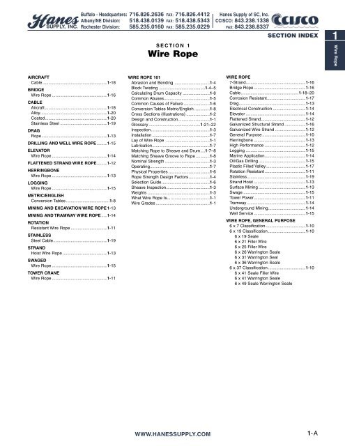
SECTION 1<br />
<strong>Wire</strong> <strong>Rope</strong><br />
WIRE ROPE <strong>101</strong><br />
Abrasion and Bending ..............................1-4<br />
Block Twisting .......................................1-4–5<br />
Calculating Drum Capacity .......................1-8<br />
Common Abuses.......................................1-5<br />
Common Causes of Failure ......................1-6<br />
Conversion Tables Metric/English .............1-8<br />
Cross Sections (Illustrations) ....................1-2<br />
Design and Construction...........................1-1<br />
Glossary ............................................1-21–22<br />
Inspection..................................................1-3<br />
Installation .................................................1-7<br />
Lay of <strong>Wire</strong> <strong>Rope</strong> .....................................1-1<br />
Lubrication.................................................1-7<br />
Matching <strong>Rope</strong> to Sheave and Drum....1-7–8<br />
Matching Sheave Groove to <strong>Rope</strong> ............1-8<br />
Nominal Strength ......................................1-3<br />
Operating...................................................1-7<br />
Physical Properties ...................................1-6<br />
<strong>Rope</strong> Strength Design Factors..................1-4<br />
Selection Guide.........................................1-6<br />
Sheave Inspection.....................................1-3<br />
Weights .....................................................1-3<br />
What <strong>Wire</strong> <strong>Rope</strong> Is... .................................1-1<br />
<strong>Wire</strong> Grades ..............................................1-1<br />
WWW.HANESSUPPLY.COM<br />
<strong>Hanes</strong> <strong>Supply</strong> of SC, <strong>Inc</strong>.<br />
CCISCO: 843.238.1338<br />
FAX: 843.238.8337<br />
SECTION INDEX<br />
WIRE ROPE<br />
7-Strand...................................................1-16<br />
Bridge <strong>Rope</strong> ............................................1-16<br />
Cable .................................................1-18–20<br />
Corrosion Resistant.................................1-17<br />
Drag.........................................................1-13<br />
Electrical Construction ............................1-14<br />
Elevator ...................................................1-14<br />
Flattened Strand......................................1-12<br />
Galvanized Structural Strand ..................1-16<br />
Galvanized <strong>Wire</strong> Strand ..........................1-12<br />
General Purpose.....................................1-10<br />
Herringbone ............................................1-13<br />
High Performance ...................................1-12<br />
Logging ...................................................1-15<br />
Marine Application...................................1-14<br />
Oil/Gas Drilling ........................................1-15<br />
Plastic Filled Valley..................................1-17<br />
Rotation Resistant...................................1-11<br />
Stainless..................................................1-19<br />
Strand Hoist ............................................1-13<br />
Surface Mining ........................................1-13<br />
Swage .....................................................1-15<br />
Tower Power............................................1-11<br />
Tramway ..................................................1-14<br />
Underground Mining................................1-14<br />
Well Service ............................................1-15<br />
WIRE ROPE, GENERAL PURPOSE<br />
6 x 7 Classification ..................................1-10<br />
6 x 19 Classification ................................1-10<br />
6 x 19 Seale<br />
6 x 21 Filler <strong>Wire</strong><br />
6 x 25 Filler <strong>Wire</strong><br />
6 x 26 Warrington Seale<br />
6 x 31 Warrington Seal<br />
6 x 36 Warrington Seale<br />
6 x 37 Classification ................................1-10<br />
6 x 41 Seale Filler <strong>Wire</strong><br />
6 x 41 Warrington Seale<br />
6 x 49 Seale Warrington Seale<br />
1-A<br />
1<br />
<strong>Wire</strong> <strong>Rope</strong>
1<br />
<strong>Wire</strong> <strong>Rope</strong><br />
NOTES<br />
1-B<br />
Buffalo - Headquarters: 716.826.2636 FAX: 716.826.4412<br />
Albany/NE Division: 518.438.0139 FAX: 518.438.5343<br />
Rochester Division: 585.235.0160 FAX: 585.235.0229<br />
WWW.HANESSUPPLY.COM<br />
<strong>Hanes</strong> <strong>Supply</strong> of SC, <strong>Inc</strong>.<br />
CCISCO: 843.238.1338<br />
FAX: 843.238.8337
What <strong>Wire</strong> <strong>Rope</strong> Is...<br />
A wire rope is a piece of flexible, multiwired,<br />
stranded machinery made of many<br />
precision parts.<br />
Usually a wire rope consists of a core<br />
member, around which a number of multiwired<br />
strands are “laid” or helically bent.<br />
There are two general types of cores for<br />
wire rope - fiber cores an wire cores. The<br />
fiber core may be made from natural or<br />
synthetic fibers. The wire core can be an<br />
Independent <strong>Wire</strong> <strong>Rope</strong> Core (IWRC), or<br />
a Strand Core (SC).<br />
The purpose of the core is to provide<br />
support and maintain the position of the<br />
outer strands during operation.<br />
Any number of multi-wired strands may<br />
be laid around the core. The most popular<br />
arrangement is six strands around the<br />
core, as this combination gives the best<br />
balance.<br />
The number of wires per strand may<br />
vary from 3 to 91, with the majority of wire<br />
ropes failing into the 7-wire, 19-wire, or<br />
37-wire strand categories.<br />
Buffalo - Headquarters: 716.826.2636 FAX: 716.826.4412<br />
Albany/NE Division: 518.438.0139 FAX: 518.438.5343<br />
Rochester Division: 585.235.0160 FAX: 585.235.0229<br />
Core Strand<br />
<strong>Wire</strong><br />
<strong>Wire</strong> <strong>Rope</strong><br />
The “lays” of <strong>Wire</strong> <strong>Rope</strong><br />
“Lay” of a wire rope is simply a description of the way wires and strands<br />
are placed during construction. Right lay and left lay refer to the direction<br />
of strands. Right lay means that the strands pass from left to right across<br />
the rope. Left lay means just the opposite: strands pass from right to left.<br />
Regular lay and lang lay describe the way wires are placed within each<br />
strand. Regular lay means that wires in the strands are laid opposite in<br />
direction to the lay of the strands. Lang lay means that wires are laid in<br />
the same direction as the lay of the strands.<br />
Most of the wire rope used is right<br />
lay, regular lay. This specification has<br />
the widest range of applications and<br />
meets the requirements of most<br />
equipment. In fact, other lay specifications<br />
are considered exceptions and<br />
must be requested when ordering.<br />
Left Lay REGULAR LAY<br />
Here are some exceptions<br />
Lang lay is recommended for many<br />
excavating, construction, and mining<br />
applications, including draglines, hoist<br />
lines, dredgelines and other similar Left Lay LANG LAY<br />
lines. Here's why: Lang lay ropes are<br />
more flexible than regular lay ropes.<br />
They also have greater wearing surface<br />
per wire than regular lay ropes.<br />
Where properly recommended,<br />
installed and used, lang lay ropes can<br />
Right Alternate Lay<br />
be used to greater advantage than<br />
regular lay ropes. However, lang lay<br />
ropes are more susceptible to the<br />
abuses of bending over small diameter<br />
sheaves, pinching in undersize<br />
sheave grooves, crushing when winding<br />
on drums, and failing due to<br />
Right Lay REGULAR LAY<br />
excessive rotation. Left lay rope has<br />
greatest usage in oil fields on rod and<br />
tubing lines, blast hole rigs, and spudders<br />
where rotation of right lay rope<br />
would loosen couplings. The rotation<br />
of a left lay rope tightens a standard<br />
coupling.<br />
Right Lay LANG LAY<br />
<strong>Wire</strong> <strong>Rope</strong> <strong>101</strong><br />
WWW.HANESSUPPLY.COM<br />
<strong>Hanes</strong> <strong>Supply</strong> of SC, <strong>Inc</strong>.<br />
CCISCO: 843.238.1338<br />
FAX: 843.238.8337<br />
<strong>Wire</strong> <strong>Rope</strong><br />
<strong>Wire</strong> <strong>Rope</strong> Design & Construction<br />
<strong>Wire</strong> ropes are composed of independent parts–wires, strands and coresthat<br />
continuously interact with each other during service.<br />
<strong>Wire</strong> rope engineers design those parts in differing steel grades, finishes<br />
and a variety of constructions to attain the best balance of strength,<br />
abrasion resistance, crush resistance, bending fatigue resistance and corrosion<br />
resistance for each application.<br />
To select the best wire rope for each application, one must know the<br />
required performance characteristics for the job and enough about wire<br />
rope design to select the optimum combination of wire rope properties.<br />
The following information is presented as a basic guide. <strong>Hanes</strong> <strong>Supply</strong><br />
engineers and field service specialists are available to provide more specific<br />
recommendations.<br />
Strand Constructions<br />
Strands are designed with various combinations of wires and wire sizes to<br />
produce the desired resistance to fatigue and abrasion. Generally, a small<br />
number of large wires will be more abrasion resistant and less fatigue<br />
resistant than a large number of small wires.<br />
Single Size<br />
The basic strand construction has wires of the same<br />
size wound around a center.<br />
Seale<br />
Large outer wires with the same number of smaller inner<br />
wires around a core wire. Provides excellent abrasion<br />
resistance but less fatigue resistance. When used with<br />
an IWRC, it offers excellent crush resistance over drums.<br />
Filler <strong>Wire</strong><br />
Small wires fill spaces between large wires to produce<br />
crush resistance and a good balance of strength, flexibility<br />
and resistance to abrasion.<br />
Warrington<br />
Outer layer of alternately large and small wires provides<br />
good flexibility and strength but low abrasion and crush<br />
resistance.<br />
Many commonly used wire ropes use combinations of these basic constructions.<br />
Seale Filler <strong>Wire</strong> Filler <strong>Wire</strong> Seale Warrington Seale Seale Warrington Seale<br />
Multiple Operation<br />
One of the above strand designs may be covered with<br />
one or more layers of uniform-sized wires.<br />
Finish<br />
Bright finish is suitable for most applications. Galvanized finish is available<br />
for corrosive environments. Plastic jacketing is also available on some<br />
constructions.<br />
<strong>Wire</strong> Grades<br />
The most common steel wire grades are: IPS (Improved Plow Steel), EIP<br />
(Extra Improved Plow Steel) and EEIP (Extra Extra Improved Plow Steel).<br />
Stainless Steels and other special grades are provided for special applications.<br />
Most wire ropes are made with round wires. Both triangular and shaped<br />
wires are also used for special constructions. Generally, the higher the<br />
strength of the wire, the lower its ductility will be.<br />
1-1<br />
1<br />
<strong>Wire</strong> <strong>Rope</strong>
1<br />
<strong>Wire</strong> <strong>Rope</strong><br />
<strong>Wire</strong> <strong>Rope</strong><br />
1-2<br />
Buffalo - Headquarters: 716.826.2636 FAX: 716.826.4412<br />
Albany/NE Division: 518.438.0139 FAX: 518.438.5343<br />
Rochester Division: 585.235.0160 FAX: 585.235.0229<br />
<strong>Wire</strong> <strong>Rope</strong> Cross Sections (past & present)<br />
6 x 7<br />
Poly Core<br />
6 x 24<br />
(Mooring Line)<br />
6 x 36<br />
Filler <strong>Wire</strong><br />
6 x 49*<br />
Filler <strong>Wire</strong>-Seale<br />
6 x 8<br />
Style D<br />
Flattened Strand<br />
18 x 7<br />
Non-Rotating<br />
1 x 3<br />
Strand<br />
* Not readily available any longer<br />
6 x 12<br />
(Marine <strong>Rope</strong>)<br />
6 x 25<br />
Filler <strong>Wire</strong><br />
6 x 36<br />
Warrington-Seale<br />
6 x 49<br />
Warrington-Seale<br />
6 x 25<br />
Style B<br />
Flattened Strand<br />
19 x 7<br />
Non-Rotating<br />
1 x 7<br />
Strand<br />
<strong>Wire</strong> <strong>Rope</strong> <strong>101</strong><br />
6 x 17<br />
Filler <strong>Wire</strong><br />
6 x 26<br />
Warrington-Seale<br />
6 x 37*<br />
Warrington<br />
6 x 55*<br />
Seale-Warrington<br />
6 x 30<br />
Style G<br />
Flattened Strand<br />
7 x 7<br />
Aircraft Cable<br />
1 x 19<br />
Strand<br />
6 x 19<br />
Seale<br />
6 x 27*<br />
Seale<br />
6 x 41<br />
Warrington-Seale<br />
6 x 61*<br />
Filler-<strong>Wire</strong> Seale<br />
6 x 42<br />
(Tiller <strong>Rope</strong>)<br />
7 x 19<br />
Aircraft Cable<br />
WWW.HANESSUPPLY.COM<br />
<strong>Hanes</strong> <strong>Supply</strong> of SC, <strong>Inc</strong>.<br />
CCISCO: 843.238.1338<br />
FAX: 843.238.8337<br />
1 x 37<br />
Strand<br />
6 x 19<br />
Warrington<br />
6 x 31*<br />
Filler <strong>Wire</strong><br />
6 x 41*<br />
Seale-Filler <strong>Wire</strong><br />
8 x 19*<br />
Seale<br />
5 x 19*<br />
(Marine Clad <strong>Rope</strong>)<br />
7 x 7 x 7<br />
Cable-Laid<br />
7 x 6 x 41<br />
IWRC Cable-Laid<br />
6 x 21<br />
Filler <strong>Wire</strong><br />
6 x 31<br />
Warrington-Seale<br />
6 x 46<br />
Seale-Filler <strong>Wire</strong><br />
8 x 25<br />
Filler <strong>Wire</strong><br />
6 x 3 x 19<br />
(Spring Lay <strong>Rope</strong>)<br />
7 x 7 x 19<br />
Cable-Laid
Buffalo - Headquarters: 716.826.2636 FAX: 716.826.4412<br />
Albany/NE Division: 518.438.0139 FAX: 518.438.5343<br />
Rochester Division: 585.235.0160 FAX: 585.235.0229<br />
Abrasion Resistance Fatigue Resistance<br />
...DECREASES<br />
with Smaller wires<br />
...INCREASES<br />
with Larger wires<br />
Nominal Strengths & Weights<br />
<strong>Wire</strong> <strong>Rope</strong> 6 x 19 Class - 6 x 37 Class<br />
...DECREASES<br />
with Fewer wires<br />
...INCREASES<br />
with More wires<br />
Nominal Strength (Tons)<br />
Dia.<br />
IPS EIPS Approx. Wt/Ft (lbs)<br />
(in) Fiber Core IWRC IWRC Fiber Core IWRC<br />
3/16 1.55 1.67 – .059 .065<br />
1/4 2.74 2.94 3.40 .105 .116<br />
5/16 4.26 4.58 5.27 .164 .18<br />
3/8 6.10 6.56 7.55 .236 .26<br />
7/16 8.27 8.89 10.2 .32 .35<br />
1/2 10.7 11.5 13.3 .42 .46<br />
9/16 13.5 14.5 16.8 .53 .59<br />
5/8 16.7 17.9 20.6 .66 .72<br />
3/4 23.8 25.6 29.4 .95 1.04<br />
7/8 32.2 34.6 39.8 1.29 1.42<br />
1 41.8 44.9 51.7 1.68 1.85<br />
1-1/8 52.6 56.5 65.0 2.13 2.34<br />
1-1/4 64.6 69.4 79.9 2.63 2.89<br />
1-3/8 77.7 83.5 96. 3.18 3.50<br />
1-1/2 92.0 98.9 114. 3.78 4.16<br />
1-5/8 107. 115. 132. 4.44 4.88<br />
1-3/4 124. 133. 153. 5.15 5.67<br />
1-7/8 141. 152. 174. 5.91 6.50<br />
2 160. 172. 198. 6.72 7.39<br />
2-1/8 179. 192. 221. 7.59 8.35<br />
2-1/4 200. 215. 247. 8.51 9.36<br />
2-3/8 222. 239. 274. 9.48 10.4<br />
2-1/2 244. 262. 302. 10.5 11.6<br />
2-5/8 268. 288. 331. 11.6 12.8<br />
2-3/4 292. 314. 361. 12.7 14.0<br />
2-7/8 317. 341. 393. 13.9 15.3<br />
3 – 370. 425. – 16.6<br />
3-1/8 – 399. 458. – 18.0<br />
3-1/4 – 429. 492. – 19.5<br />
3-3/8 – 459. 529. – 21.0<br />
3-1/2 – 491. 564. – 22.6<br />
Available galvanized at 10% lower strengths, or in equivalent strengths on special<br />
request<br />
Inspection–The key to longer, safer wire rope use<br />
Any wire rope in use should be inspected on a regular basis. You have too<br />
much at stake in lives and equipment to ignore thorough examination of<br />
the rope at prescribed intervals.<br />
The purpose of inspection is to accurately estimate the service life and<br />
strength remaining in a rope so that maximum service can be had within<br />
the limits of safety. Results of the inspection should be recorded to provide<br />
a history of rope performance on a particular job. On most jobs wire rope<br />
must be replaced before there is any risk of failure. A rope broken in service<br />
can destroy machinery and curtail production. It can also kill.<br />
Because of the great responsibility involved in ensuring safe rigging on<br />
equipment, the person assigned to inspect should know wire rope and its<br />
operation thoroughly. Inspections should be made regularly and the results<br />
recorded.<br />
When inspecting the rope, the condition of the drum, sheaves, guards,<br />
cable clamps and other end fittings should be noted. The condition of<br />
these parts affects rope wear: any defects detected should be repaired.<br />
To ensure rope soundness between inspections, all workers should participate.<br />
The operator can be most helpful by watching the ropes under his<br />
control. If any accident involving the ropes occurs, the operator should<br />
immediately shut down his equipment and report the accident to his supervisor.<br />
The equipment should be inspected before resuming operation.<br />
The Occupational Safety and Health Act has made periodic inspection<br />
mandatory for most wire rope applications. We can help you locate regulations<br />
that apply to most applications, give us a call!<br />
Just looking at the rope Is not enough<br />
When an inspector takes a look at a rope, he may see sections showing<br />
excessive wear. By flagging the rope, he can quickly determine where the<br />
rope is rubbing or contacting parts of the equipment, and then repair,<br />
replace, or modify the condition causing the wear.<br />
<strong>Wire</strong> <strong>Rope</strong> <strong>101</strong><br />
Sheave Inspection<br />
WWW.HANESSUPPLY.COM<br />
<strong>Hanes</strong> <strong>Supply</strong> of SC, <strong>Inc</strong>.<br />
CCISCO: 843.238.1338<br />
FAX: 843.238.8337<br />
<strong>Wire</strong> <strong>Rope</strong><br />
Inspection of sheaves is a relatively simple, yet very vital task. A sheave<br />
groove gauge, usually obtainable from a wire rope manufacturer, is used<br />
to check the grooves in a sheave. Hold the gauge perpendicular to the<br />
surface of the groove to observe properly the groove size and contour,<br />
as in this illustration.<br />
Allowable <strong>Rope</strong> 1/2 Allowable<br />
Nominal <strong>Rope</strong> oversize <strong>Rope</strong> Oversize<br />
Dia. (in) (in) (in)<br />
0 - 3/4 + 1/32 + 1/64<br />
13/16 - 1-1/8 +3/64 +3/128<br />
1-3/16 - 1-1/2 + 1/16 + 1/32<br />
1-9/16 - 2-1/4 +3/32 + 3/64<br />
2-5/16 - and larger +1/8 +1/16<br />
Photo shows new gauge and worn sheave. This new gauge<br />
is designed with one-half the allowable oversize (see table).<br />
Using the new gauge, when you do not see light, the sheave is OK. When you do see light under the<br />
new gauge, the sheave should be replaced.<br />
Sheaves Should be Checked for:<br />
1. Correct groove diameter<br />
2. Roundness or contour to give proper support to the rope<br />
3. Small holes, cracks, uneven surfaces, or other defects that might be<br />
detrimental to the rope<br />
4. Extreme deep wear<br />
A sheave should also be checked to make sure it turns freely, is<br />
properly aligned, has no broken or cracked flanges, and has bearings that<br />
work properly.<br />
Drums should also be inspected for signs of wear that could damage<br />
rope.<br />
Plain-faced or smooth drums can develop grooves or impressions that<br />
prevent rope from winding properly. Repair by resurfacing the face or<br />
replacing the lagging.<br />
Scrubbing will occur if the rope tends to close wind. If the tendency is to<br />
open winding, the rope will encounter abnormal abuse as the second layer<br />
forces itself down between the open wraps of the first layer on the drum.<br />
Operating with a smooth drum calls for special care. Be sure the rope is<br />
always tightly wound and thread layed on the first layer. Any loosening of<br />
the line is easily observed as the winding will be bad and the rope will be<br />
coming off with a series of “bad spots.”<br />
Grooved drums should be examined for tight or corrugated grooves and<br />
for differences in depth or pitch that could damage the second and subsequent<br />
layers. Worn grooves can develop extremely sharp edges that shave<br />
away small particles of steel from the rope. Correct this condition by grinding<br />
or filing a radius to replace the sharp edge.<br />
Drum flanges, as well as the starter, filler and riser strips, should be<br />
checked. Excessive wear here often causes unnecessary rope abuse at<br />
the change of layers and cross-over points.<br />
Other places of contact such as rollers, scrub boards, guides and end<br />
attachments should also be inspected.<br />
Measure the widest diameter<br />
<strong>Rope</strong>s and sheave grooves must be precisely fitted to each other to get<br />
the most service out of your wire rope<br />
dollar. Make measurement of rope<br />
diameter a normal part of your inspection<br />
program.<br />
There's only one right way to measure<br />
rope diameter: use machinist's<br />
calipers and be sure to measure the<br />
widest diameter. These drawings compare<br />
the right way with the wrong way.<br />
This method is not only useful for<br />
measuring the diameter of a new rope,<br />
but also for determining the amount of<br />
wear and compression that has<br />
occurred while the rope has been in<br />
use. Accurate recording of this information<br />
is essential in helping to decide<br />
when to replace wire rope.<br />
Right Way. Set<br />
the machinist’s<br />
caliper to read<br />
the widest diameter.<br />
Vernier<br />
scale reads to<br />
1/128th of an<br />
inch.<br />
Wrong Way.<br />
This is the<br />
wrong way to<br />
measure wire<br />
rope diameter.<br />
Widest diameter<br />
is not being<br />
read.<br />
1-3<br />
1<br />
<strong>Wire</strong> <strong>Rope</strong>
1<br />
<strong>Wire</strong> <strong>Rope</strong><br />
<strong>Wire</strong> <strong>Rope</strong><br />
1-4<br />
Buffalo - Headquarters: 716.826.2636 FAX: 716.826.4412<br />
Albany/NE Division: 518.438.0139 FAX: 518.438.5343<br />
Rochester Division: 585.235.0160 FAX: 585.235.0229<br />
Abrasion and Bending<br />
The “X-Chart” - Abrasion Resistance Vs. Bending Fatigue<br />
Resistance<br />
While there is a possibility, there is little likelihood that an application can<br />
be found for which there is a precisely suitable wire rope–one that can satisfy<br />
every indicated requirement.<br />
As with all engineering design problems, feasible solutions demand<br />
compromise to some degree. At times, it becomes necessary to settle for<br />
less than optimum resistance to abrasion in order to obtain maximum flexibility;<br />
the latter being a more important requirement for the given job. A<br />
typical example of this kind of trade-off would be in selecting a highly flexible<br />
rope on an overhead crane. Conversely, in a haulage installation, a<br />
rope with greater resistance to abrasion would be chosen despite the fact<br />
that such ropes are markedly less flexible.<br />
Two compelling factors that govern most decisions as to the selection of<br />
a wire rope are abrasion resistance, and resistance to bending fatigue.<br />
Striking a proper balance with respect to these two important characteristics<br />
demands judgment of a very high order. A graphic presentation of just<br />
such comparison of qualities between the most widely used rope constructions<br />
and others is given by means of X-chart.<br />
Referring to this chart when selecting a rope, the mid-point (at the X)<br />
comes closest to an even balance between abrasion resistance and resistance<br />
to bending fatigue. Reading up or down along either leg of the X, the<br />
inverse relationship becomes more apparent as one quality increases and<br />
the other decreases.<br />
Effect of Sheave Size<br />
<strong>Wire</strong> ropes are manufactured in a great variety of constructions to meet<br />
the varying demands of wire rope usage. Where abrasion is an important<br />
factor, the rope must be made of a coarse construction containing relatively<br />
large wires. In other cases, the great amount of bending to which the<br />
rope is subjected is more important. Here, a more flexible construction,<br />
containing many relatively small wires, is required. In either case, however,<br />
if the rope operates over inadequate size sheaves, the severe bending<br />
stresses imposed will cause the wires to break from fatigue, even though<br />
actual wear is slight. The smaller the diameter of the sheave, the sooner<br />
these fatigue breaks will occur and the shorter rope life becomes.<br />
Another undesirable effect of small sheaves is accelerated wear of both<br />
rope and sheave groove. The pressure per unit area of rope on sheave<br />
groove for a given load<br />
is inversely proportional<br />
No. of Outside <strong>Wire</strong>s Per Strand<br />
6 6x7<br />
9 6x19 S<br />
10 6 X 21 FW<br />
12<br />
Flattened<br />
Strand<br />
12 6x25 FW<br />
12 6x31 WS<br />
14 6x36 WS<br />
16 6x49 FWS<br />
18 6x64 SFWS<br />
The <strong>Wire</strong> <strong>Rope</strong> industry refers to this as the X-Chart. It<br />
serves to illustrate the inverse relationship between abrasion<br />
resistance & resistance to bending fatigue in a representative<br />
number of the most widely used wire ropes.<br />
Least Resistance to Bending Fatigue Greatest<br />
Least • Resistance to Abrasion Greatest<br />
Proper Sheave and Drum Sizes<br />
Suggested Min.<br />
Construction D/d* ratio D/d* ratio<br />
6x7 72 42<br />
19x7 or 18x7<br />
Rotation Resistant<br />
51 34<br />
6x19 Seale 51 34<br />
6x27 H flattened strand 45 30<br />
6x31 V flattened strand 45 30<br />
6x21 filler wire 45 30<br />
6x25 filler wire 39 26<br />
6x31 Warrington Seale 39 26<br />
6x36 Warrington Seale 35 23<br />
8x19 Seale 41 27<br />
8x25 filler wire 32 21<br />
6x41 Warrington Seale 32 21<br />
6x42 tiller 21 14<br />
*D = Tread Diameter of Sheave<br />
d = Nominal Diameter of <strong>Rope</strong><br />
<strong>Wire</strong> <strong>Rope</strong> <strong>101</strong><br />
to the size of the<br />
sheave. In other words,<br />
the smaller the sheave<br />
the greater the rope<br />
pressure per unit area<br />
on the groove. Both<br />
sheaves and rope life<br />
can obviously be prolonged<br />
by using the<br />
proper diameter sheave<br />
for the size and construction<br />
of rope.<br />
Sheave diameter can<br />
also influence rope<br />
strength. When a wire<br />
rope is bent around a<br />
sheave, there is a loss<br />
of effective strength due<br />
to the inability of the<br />
individual strands and<br />
wires to adjust themselves<br />
entirely to their<br />
changed position. Tests<br />
show that rope strength<br />
efficiency decreases to<br />
a marked degree as the<br />
sheave diameter is<br />
reduced with respect to<br />
the diameter of the<br />
rope.<br />
Therefore, it is evident<br />
that a definite relationship<br />
exists between<br />
rope service and<br />
sheave size. As a guide<br />
to rope users, wire rope<br />
WWW.HANESSUPPLY.COM<br />
<strong>Hanes</strong> <strong>Supply</strong> of SC, <strong>Inc</strong>.<br />
CCISCO: 843.238.1338<br />
FAX: 843.238.8337<br />
manufacturers have established standards for sheave sizes to be used<br />
with various rope constructions. To secure the most economical service,<br />
it is important that the suggested size of sheaves given here be used.<br />
<strong>Rope</strong> Strength Design Factors<br />
The rope strength design factor is the ratio of the rated strength of the<br />
rope to its operating stress. If a particular rope has a rated strength of<br />
100,000 lbs. and is working under an operating stress of 20,000 lbs., it<br />
has a rope strength design factor of 5. It is operating at one-fifth or 20%<br />
of its rated strength.<br />
Many codes refer to this factor as the “Safety Factor” which is a misleading<br />
term, since this ratio obviously does not include the many facets<br />
of an operation which must be considered in determining safety.<br />
<strong>Wire</strong> rope is an expendable item - a replacement part of a machine or<br />
installation. For economic and other reasons, some installations require<br />
ropes to operate at high stresses (low rope strength design factors). On<br />
some installations where high risk is involved, high rope strength design<br />
factors must be maintained. However, operating and safety codes exist for<br />
most applications and these codes give specific factors for usage. When a<br />
machine is working and large dynamic loadings (shock loadings) are<br />
imparted to the rope, the rope strength design factor will be reduced<br />
which could result in overstressing of the rope. Reduced rope strength<br />
design factors frequently result in reduced service life of wire rope.<br />
O.S.H.A. (A.N.S.I.) Removal Criteria 5. ANSI Safety Codes, Standards<br />
and Requirements–rope must be removed from service when diameter<br />
loss or wire breakage occurs as follows:<br />
Diameter Loss<br />
Original Loss<br />
Dia. (in) (in)<br />
5/16 & Smaller 1/64<br />
3/8 – 1/2 1/32<br />
9/16 –3/4 3/64<br />
7/8 – 1-1/8 1/16<br />
1-1/4 – 1-1/2 3/32<br />
No. of <strong>Wire</strong> Breaks<br />
No. broken <strong>Wire</strong>s No. Broken <strong>Wire</strong>s<br />
In Running <strong>Rope</strong>s In Standing <strong>Rope</strong>s<br />
ANSI In One In One In One At End<br />
No. Equipment <strong>Rope</strong> Lay Strand <strong>Rope</strong> Lay Connection<br />
B30.2 Overhead & Gantry Cranes 12 4 NS** NS**<br />
B30.4 Portal, Tower & Pillar Cranes 6 3 3 2<br />
B30.5 Crawler, Locomotive & Truck Cranes 6 3 3 2<br />
B30.6 Derricks 6 3 3 2<br />
B30.7 Base Mounted Drum Hoists 6 3 3 2<br />
B30.8 Floating Cranes & Derricks 6 3 3 2<br />
A10.4 Personnel Hoists 6* 3 2* 2<br />
A10.5 Material Hoists 6* NS** NS** NS**<br />
* Also remove for 1 valley break. OSHA requires monthly record keeping of wire rope<br />
condition.<br />
** NS = Not Specified<br />
Note: Current industry recommendations & OSHA standards based upon the use of<br />
steel sheaves. The manufacturer of plastic or synthetic sheaves or liners should be<br />
consulted to their recommendation on the safe application of their product, and possible<br />
revision in rope inspection criteria when used with their product.<br />
Block Twisting<br />
Block twisting or “cabling” is one of the most frequently encountered wire<br />
rope problems in the construction field. When this problem occurs, the<br />
wire rope is most often blamed, and other equally important factors in the<br />
operation are overlooked.<br />
Personnel experienced with handling of wire rope know that conventional<br />
wire ropes will twist or unlay slightly, when a load is applied. In a reeved<br />
hoisting system, subjected to loading and unloading, such as a load hoisting<br />
line, this results in block twisting and possibly distortion of the wire<br />
rope. Cabling of the block most frequently occurs as the load in the wire<br />
rope is released, and the "falls" are in a lowered position. Cabling may be<br />
considered as the twisting of the block beyond one-half of a revolution<br />
(180 O twisting) of the traveling block. When this condition occurs, the operator<br />
shows good judgment in not making additional lifts, until the conditions<br />
causing the problem are corrected.<br />
The following machine and site conditions should be investigated for<br />
possible improvement in block twisting.
Buffalo - Headquarters: 716.826.2636 FAX: 716.826.4412<br />
Albany/NE Division: 518.438.0139 FAX: 518.438.5343<br />
Rochester Division: 585.235.0160 FAX: 585.235.0229<br />
Block Twisting (cont.)<br />
1. Reduce wire rope length. Longer rope lengths cause more twisting than<br />
short rope lengths. This applies particularly to the amount of wire rope in<br />
the “falls.”<br />
2. Reduce the amount of load lifted. Heavily loaded ropes have more<br />
torque and twist than lightly loaded ropes. This condition would also<br />
apply to the speed of loading or “shock” loading, since this condition<br />
also causes higher wire rope loading.<br />
3. Eliminate “odd-part” reeving, where the wire rope “dead-end” is on the<br />
traveling block. <strong>Wire</strong> rope torque, from the application of load, is greatest<br />
at the rope dead-end.<br />
4. Relocate the rope dead-end at the boom, in order to increase the separation<br />
between the dead-end and the other rope parts. This applies a<br />
stabilizing load directly to the traveling block. The original equipment<br />
manufacturer should be consulted before making this modification.<br />
5. <strong>Inc</strong>rease sheave size. This increases the amount of separation between<br />
wire rope parts and may improve the situation by applying stabilizing<br />
loads and reducing the amount of rope torque transmitted to the traveling<br />
block.<br />
6. Restrain the twisting block with a “tag” line. One or more of the foregoing<br />
suggestions may eliminate the problem without resorting to “specialized”<br />
wire rope which may not only be difficult to locate but expensive as well.<br />
The use of special “rotation resistant” wire ropes will not likely be<br />
required unless the intended length of rope “falls” exceeds 100 feet, or the<br />
length of the load hoisting line exceeds 600 feet. In the event these latter<br />
conditions exist, the user should also anticipate using a combination of the<br />
“rotation resistant” wire rope and the foregoing field suggestions for the<br />
more severe problems.<br />
Common <strong>Wire</strong> <strong>Rope</strong> Abuses<br />
Neglect and abuse are the two chief enemies of wire rope life. One costly<br />
form of neglect is lack of proper field lubrication. Abuse takes many forms:<br />
improper reeling or unreeling, wrong size or worn sheaves, improper storage,<br />
bad splicing are a few.<br />
Condition of Machinery<br />
<strong>Wire</strong> rope performance depends upon the condition of the equipment on<br />
which it operates; poorly maintained equipment will usually result in<br />
reduced rope life.<br />
Effects of Shock-Loading and Vibration<br />
The destructive effects of jerking or shock-loading are visually noticeable.<br />
Vibration has somewhat the same effect, and is equally destructive. An<br />
individual shock may be slight but many rapidly repeated slight shocks<br />
can have the effect of several large shocks.<br />
Vibration which occurs directly above a load is often unavoidable.<br />
“Whipping” of the section of rope immediately above the load is also<br />
common. In these cases, rapid wire fatigue is possible. For reasons of<br />
safety, this section should be examined regularly.<br />
<strong>Wire</strong> rope failure is usually cumulative. Each repeated overstress brings<br />
the rope nearer to failure. Thus, a wire rope may become fatigued to a<br />
point close to failure under a heavy load and actually fail under a much<br />
lighter load.<br />
Overstressing<br />
In any hoisting operation, there should be no slack in the wire rope when<br />
the load is applied. Otherwise, the resulting stress will be excessive.<br />
Overstressing can also be the result of too-rapid acceleration or deceleration.<br />
<strong>Wire</strong> rope will withstand considerable stress if the load is applied<br />
slowly. As with ordinary twine, a quick snap will cause overstressing and<br />
breakage. This applies both when starting to lift a load, and when bringing<br />
it to a stop.<br />
Corrosion<br />
Corrosion can seriously shorten wire rope life, both by metal loss and by<br />
formation of corrosion pits in the wires. These pits act as stress-concentration<br />
points in the wires in much the same manner as do nicks.<br />
<strong>Wire</strong> rope left on machines shut down for long periods of time deteriorates<br />
rapidly. To preserve the rope for future use, it should be removed, cleaned<br />
and thoroughly lubricated.<br />
Causes of Corrosion Damage<br />
Pitting, erosion, and surface effects of many different types can all result<br />
in corrosion damage. Because they tend to increase corrosion, the following<br />
conditions should be considered and noted when applicable, during<br />
the ordering of wire rope - acid and alkaline solutions, gases, fumes, brine<br />
<strong>Wire</strong> <strong>Rope</strong> <strong>101</strong><br />
WWW.HANESSUPPLY.COM<br />
<strong>Hanes</strong> <strong>Supply</strong> of SC, <strong>Inc</strong>.<br />
CCISCO: 843.238.1338<br />
FAX: 843.238.8337<br />
<strong>Wire</strong> <strong>Rope</strong><br />
and salt air, sulphurous compounds, and high humidity and temperature.<br />
Lubricants are readily available to reduce the severity of attack of most of<br />
these conditions.<br />
Effects of Severe Heat<br />
Where wire rope is subjected to severe heat (e.g., foundry cranes) it will<br />
not give the service expected because it will deteriorate more quickly.<br />
<strong>Wire</strong> ropes exposed to hot-metal handling or other extreme heat<br />
sometimes require independent wire rope cores.<br />
Shifting <strong>Rope</strong>s From One Job to Another<br />
Sometimes an idle wire rope from one operation is installed on another<br />
to keep the rope in continuous service. This extremely poor practice is<br />
an expensive “economy.”<br />
Because wire rope tends to “set” to the conditions of its particular<br />
operating job, the differing bends, abrasions, and stresses of a new<br />
operation can produce premature failure. Therefore, for maximum life<br />
and efficiency, a rope should be used only on the job for which it has<br />
been specified.<br />
Machinery Operation<br />
Some operators are harder on their machinery than others and as a<br />
result they get shorter rope life. In certain instances, enough extra work<br />
is done to more than offset the additional wear-and-tear on equipment<br />
and wire rope. The operation may be more efficient from the production<br />
standpoint as a result, but those in charge of rope purchases should be<br />
made aware of the probable reduction in rope life and increased rope<br />
costs.<br />
Examples of Common <strong>Wire</strong> <strong>Rope</strong> Abuses<br />
Crushing. Because of loose winding<br />
on drum, rope was pulled in between<br />
underlying wraps and crushed out of<br />
shape.<br />
Too sudden load release. The sudden<br />
release of a load cause birdcaging.<br />
Here individual strands open away<br />
from each other, displacing the core.<br />
Lack of lubrication. Premature breakage<br />
of wires resulted from “locking” of<br />
strands, which was caused by insufficient<br />
lubrication.<br />
Infrequent Inspection. Neglect of periodical<br />
inspection left this rope in service<br />
too long, resulting in considerable<br />
abrasion.<br />
Improper handling. Kink or “dog leg”<br />
was caused by improper handling<br />
and/or installation. A kink causes<br />
excessive localized or spot abrasion.<br />
Reverse bending. Running this rope<br />
over one sheave and under another<br />
caused fatigue breaks in wires.<br />
Excessive exposure to elements.<br />
Too much exposure combined with<br />
surface wear and loss of lubrication<br />
caused corrosion and pitting.<br />
Too long in service. Repeated winding<br />
and overwinding of this rope on a<br />
drum while it was under heavy stress<br />
caused the unusually severe wear<br />
shown.<br />
Undersize sheave grooves. Sheaves<br />
were too small, causing strands to<br />
pinch. <strong>Wire</strong>s then fail in the valley<br />
between the strands.<br />
Poor work procedures. Damage to<br />
strands and wires resulted from electric<br />
arcing.<br />
Lack of knowledge. Here’s what<br />
occurs when a loop which has been<br />
“pulled through” and tightened remains<br />
in service.<br />
1-5<br />
1<br />
<strong>Wire</strong> <strong>Rope</strong>
1<br />
<strong>Wire</strong> <strong>Rope</strong><br />
<strong>Wire</strong> <strong>Rope</strong><br />
1-6<br />
Buffalo - Headquarters: 716.826.2636 FAX: 716.826.4412<br />
Albany/NE Division: 518.438.0139 FAX: 518.438.5343<br />
Rochester Division: 585.235.0160 FAX: 585.235.0229<br />
Physical Properties<br />
Elastic Properties of <strong>Wire</strong> <strong>Rope</strong><br />
The following discussion relates to conventional 6- or 8-strand ropes that<br />
have either fiber or steel cores; it is not applicable to rotation-resistant<br />
ropes since these constitute a separate case.<br />
<strong>Wire</strong> rope is an elastic member; it stretches or elongates under load.<br />
This stretch derives from two sources:<br />
1) constructional<br />
2) elastic<br />
In actuality, there may be a third source of stretching–a result of the<br />
rope rotating on its own axis. Such elongation, which may occur either as<br />
a result of using a swivel, or from the effect of a free-turning load, is<br />
brought about by the unlaying of the rope strands. Because the third<br />
source is a subject that is beyond the scope of this publication, discussion<br />
will be directed to constructional and elastic stretch.<br />
Constructional Stretch<br />
When a load is applied to wire rope, the helically-laid wires and strands<br />
act in a constricting manner thereby compressing the core and bringing all<br />
the rope elements into closer contact. The result is a slight reduction in<br />
diameter and an accompanying lengthening of the rope.<br />
Constructional stretch is influenced by the following factors:<br />
1) type of core (fiber or steel),<br />
2) rope construction (6x7, 6x25 FW, 6x41 WS, 8x19 S, etc.),<br />
3) length of lay,<br />
4) material.<br />
<strong>Rope</strong>s with wire strand core (WSC) or independent wire rope core<br />
(IWRC) have less constructional stretch than those with fiber core (FC).<br />
The reason for this is the fact that the steel cannot compress as much as<br />
the fiber core.<br />
Usually, constructional stretch will cease at an early stage in the rope's<br />
life. However, some fiber core ropes, if lightly loaded (as in the case of elevator<br />
ropes), may display a degree of constructional stretch over a considerable<br />
portion of their life.<br />
A definite value for determining<br />
constructional stretch cannot be<br />
assigned since it is influenced by<br />
several factors. The following table<br />
gives some idea of the approximate<br />
stretch as a percentage of<br />
rope under load.<br />
<strong>Rope</strong> Construction Approx. Stretch*<br />
6 strand FC 1/2% - 3/4%<br />
6 strand IWRC 1/4 % - 1/2%<br />
8 strand FC 3/4% - 1%<br />
* Varies with the magnitude of the loading.<br />
Elastic Stretch<br />
Elastic stretch results from recoverable deformation of the metal itself.<br />
Here, again, a quantity cannot be precisely calculated. However, the following<br />
equation can provide a reasonable approximation for a good many<br />
situations.<br />
Changes in length (ft) = Change in load (lb) x Length (ft)<br />
Area (inches2 ) x Modulus of Elasticity (psi)<br />
The modulus of elasticity is given below.<br />
Approximate Modulus of Elasticity (lbs. per square <strong>Inc</strong>h)<br />
<strong>Rope</strong> Classification Zero through 20% Loading 21 to 65% Loading*<br />
6 x 7 with fiber core 11,700,000 13,000,000<br />
6 x 19 with fiber core 10,800,000 12,000,000<br />
6 x 37 with fiber core 9,900,000 11,000,000<br />
8 x 19 with fiber core 8,100,000 9,000,000<br />
6 x 19 with IWRC 13,500,000 15,000,000<br />
6 x 37 with lWRC 12,600,000 14,000,000<br />
* Applicable to new rope, i.e., not previously loaded.<br />
General Guidelines for <strong>Wire</strong> <strong>Rope</strong> Selection<br />
Strength:<br />
<strong>Wire</strong> rope must have the strength required to handle the maximum load<br />
plus a design factor.<br />
The design factor is the ratio of the breaking strength of the rope to the<br />
maximum working load. To establish the proper design factor, several operating<br />
characteristics should be considered:<br />
speed of operation<br />
acceleration and deceleration<br />
length of rope<br />
<strong>Wire</strong> <strong>Rope</strong> <strong>101</strong><br />
number, size and<br />
location of<br />
sheaves and<br />
drums<br />
rope attachments<br />
conditions causing<br />
corrosion and<br />
abrasion<br />
danger to human<br />
life and property.<br />
WWW.HANESSUPPLY.COM<br />
<strong>Hanes</strong> <strong>Supply</strong> of SC, <strong>Inc</strong>.<br />
CCISCO: 843.238.1338<br />
FAX: 843.238.8337<br />
Fatigue Resistance<br />
Smaller wires are the key to bending performance<br />
when wire ropes are subjected<br />
to repeated bending over sheaves or<br />
drums. The more outer wires for a given<br />
size wire rope, the better the resistance<br />
to bending fatigue. The relative bending<br />
life factors of typical wire rope constructions<br />
are indicated in the following table.<br />
<strong>Rope</strong>s having a large number of small<br />
wires, however, should not be used<br />
where overwrapping on a drum takes<br />
place because they do not provide sufficient<br />
crush resistance.<br />
Abrasion Resistance<br />
Lang lay and large outer<br />
wires provide resistance to<br />
abrasion. The relationship<br />
between abrasion resistance<br />
and fatigue resistance is<br />
illustrated.<br />
Crush Resistance<br />
An IWRC (Independent <strong>Wire</strong><br />
<strong>Rope</strong> Core) and large outer<br />
wires will provide best crush<br />
resistance. Constructex rope<br />
provides the best crush<br />
resistance of any wire rope.<br />
Generally Accepted Design Factors<br />
Type of Service.......................................Minimum Factor<br />
Guy <strong>Rope</strong>s......................................................................3.5<br />
Overhead and Gantry Cranes.........................................3.5<br />
Jib and Pillar Cranes.......................................................3.5<br />
Derricks...........................................................................3.5<br />
<strong>Wire</strong> <strong>Rope</strong> Slings ...........................................................5.0<br />
Misc. Hoisting Equipment ..............................................5.0<br />
Ski Lift <strong>Rope</strong>s–slopes under 3,000 feet .........................5.0<br />
slopes over 3,000 feet ..........................4.5<br />
Haulage <strong>Rope</strong>s ...............................................................5.0<br />
Small Electric and Air Hoists ..........................................5.0<br />
Rotation Resistant <strong>Rope</strong>s–Minimum..............................5.0<br />
Recommended....................7.0<br />
Hot Ladle Cranes ...........................................................8.0<br />
Elevator Hoist and Counterweight <strong>Rope</strong>s (Passenger)<br />
500 FPM ................................................................10.25<br />
750 FPM.................................................................11.15<br />
1000 FPM...............................................................11.55<br />
Relative bending life<br />
factors of typical ropes<br />
<strong>Rope</strong> Construction Factor<br />
6x7 .57<br />
19x7 .67<br />
6x19 S .80<br />
6x21 FW .92<br />
Dyform-18 and 6 x 25 FW 1.00<br />
6x31 WS 1.09<br />
Dyform-6 and 6 x 36 WS 1.31<br />
8x25 FW 1.39<br />
6x41 WS 1.39<br />
6x49 SWS 1.54<br />
Min. Max.<br />
Resistance to Bending Fatigue<br />
x x x x x x x x x<br />
Resistance to Abrasion<br />
o o o o o o o o o<br />
6x7<br />
6x19 Seale<br />
6x21 FW<br />
6x19 Warrington<br />
6x25 FW<br />
8x19 Seale<br />
6x31<br />
6x36 WS<br />
8x25 FW<br />
6x41 WS<br />
Flexibility<br />
Fiber core, lang lay and smaller wires provide a more flexible wire rope.<br />
Installation, Operation and Maintenance<br />
Recommendation<br />
Common Causes of Failure<br />
The primary factor in wire rope performance is selecting a wire rope with<br />
the best combination of properties for the job. The service life of that rope<br />
can be greatly extended by following a planned program of installation,<br />
operation, maintenance and inspection to avoid the most common causes<br />
of wire rope failure:<br />
KINKING will result in permanent rope deformation and localized wear. It<br />
is generally caused by allowing a loop to form in a slack line and then<br />
pulling the loop down to a tight permanent set.<br />
OVERLOADING results in accelerated wear, abrasion, rope crushing and<br />
distortion on drums and sheaves, and could result in complete rope failure.<br />
DRAGGING wire rope over a bank or some other object results in localized<br />
wear, which means shorter life.<br />
IMPROPER SPOOLING results in crushed and distorted ropes and comes<br />
from careless installation and operation of the rope.<br />
WHIPPING a line, which results in many squared off broken wires, comes<br />
from jerking or running the line loose.<br />
The following recommendations are general guides for getting the<br />
longest life from your wire rope. Our engineers and field service specialists<br />
are available to provide advice in specific situations.
Installation, Operation and Maintenance<br />
Recommendation (cont.)<br />
Unloading, Unreeling and Uncoiling<br />
Suitable precautions should be taken to prevent<br />
dropping of reels or coils during unloading and moving.<br />
If the reel should collapse, it may be impossible<br />
to remove the rope without serious damage.<br />
Special care should be taken in unreeling wire<br />
rope to avoid kinking, which can result in permanent<br />
damage to the rope. The reel should be mounted on<br />
jacks or a turntable so that it will move freely. It<br />
should be unreeled straight and under enough tension<br />
to keep it from starting a loop.<br />
A coil should be unwound by rolling along the<br />
floor like a hoop. Coils should never be laid flat and<br />
the free end pulled out.<br />
Buffalo - Headquarters: 716.826.2636 FAX: 716.826.4412<br />
Albany/NE Division: 518.438.0139 FAX: 518.438.5343<br />
Rochester Division: 585.235.0160 FAX: 585.235.0229<br />
Winding on a Drum<br />
Reel<br />
Drum<br />
Proper practices for transferring<br />
rope from reel to drum:<br />
The reel should be placed<br />
as far from the drum as possible<br />
in order to avoid putting<br />
any turn into the rope.<br />
<strong>Rope</strong> should be wound<br />
Reel<br />
from top-to-top or bottom-to-<br />
Drum bottom to avoid reverse<br />
bends, which tend to make a<br />
rope harder to handle.<br />
Use enough tension to<br />
avoid kinking.<br />
There is usually only one way to install rope on a grooved drum.<br />
Right Lay <strong>Rope</strong><br />
Winding Over Drum Winding Under Drum<br />
Use Right Hand<br />
Index Finger on Top– Index Finger on Bottom–<br />
Thumb on Left Thumb on Right<br />
On ungrooved drums, the “rule of thumb” guides installation. The fist<br />
represents the drum; the index finger the wire rope; and the thumb the<br />
direction of the proper dead end location. Use the right hand for right lay<br />
ropes, the left hand for left lay ropes. For overwinding, the palm is down;<br />
for underwinding, the palm is up. Most drum anchors are set for right lay<br />
rope since it is the most common specification.<br />
Fleet<br />
Angle<br />
(Left)<br />
1-1/2"<br />
max.<br />
1/2"<br />
min.<br />
Fleet<br />
Angle<br />
(Right)<br />
1-1/2"<br />
max.<br />
1/2"<br />
min.<br />
Ungrooved Drum<br />
Left Lay <strong>Rope</strong><br />
Winding Over Drum Winding Under Drum<br />
Use Left Hand<br />
Index Finger on Top– Index Finger on Bottom–<br />
Thumb on Right Thumb on Left<br />
On installations where the rope passes over a<br />
sheave onto the drum, the maximum fleet angle<br />
(angle between the center line of the sheave<br />
and the rope) should be not more than 1-1/2<br />
degrees for a smooth-faced drum and 2<br />
degrees for a grooved drum. A 1-1/2 degree<br />
fleet angle is equivalent to 38 feet of lead for<br />
each foot of rope travel on either side of the<br />
center line of the sheave. Smaller fleet angles<br />
may result in the rope piling up on the drum.<br />
Larger fleet angles may cause excessive wear<br />
from rubbing against the flanges of the sheave<br />
as well as excessive crushing and abrasion of<br />
the rope on the drum.<br />
Break In<br />
A few trips through the working cycle at slow<br />
speed and light load will set the strands firmly in<br />
place for smooth, efficient operation.<br />
On applications using a wedge socket, such<br />
<strong>Wire</strong> <strong>Rope</strong> <strong>101</strong><br />
WWW.HANESSUPPLY.COM<br />
<strong>Hanes</strong> <strong>Supply</strong> of SC, <strong>Inc</strong>.<br />
CCISCO: 843.238.1338<br />
FAX: 843.238.8337<br />
<strong>Wire</strong> <strong>Rope</strong><br />
as drag and hoist ropes, it is also a good idea to cut off a short section of<br />
rope to allow twist to run out and to equalize the strands.<br />
Operation<br />
Skillful operation is important to wire rope performance. Rapid acceleration,<br />
shock loading and excessive vibration can cause premature rope failure.<br />
Smooth, steady application of power by the equipment operator can<br />
add significantly to wire rope service life.<br />
Shifting Wear Points<br />
Some sections of most wire ropes get more wear than others. A regular<br />
inspection program will identify points of wear and lead to wear-shift practices<br />
that will extend wire rope life.<br />
In many common situations, cutting off short lengths of the rope will<br />
redistribute the points of maximum wear:<br />
<strong>Rope</strong> on a drum with two or more layers will wear at the point where the<br />
rope starts each successive layer.<br />
Crane ropes will fatigue at an equalizer sheave. Careful inspection is<br />
required to identify fatigue points.<br />
Hoist ropes will frequently fail from vibration fatigue at sockets, clips and<br />
dead end points.<br />
On most installations, wear and fatigue are more severe on one half of<br />
the rope than the other. Changing a rope end-for-end more evenly distributes<br />
wear and fatigue from repeated bending and vibration.<br />
Lubrication<br />
Factory lubrication is not always sufficient to last the useful life of<br />
wire rope. Periodic field lubrication may be required to minimize<br />
friction and provide corrosion protection. Important guides for<br />
field lubrication:<br />
<strong>Rope</strong>s should be inspected frequently to determine the need for lubrication.<br />
Clean the rope thoroughly with a wire brush, scraper or compressed air<br />
to remove foreign material and old lubricant from the valleys between the<br />
strands and the spaces between the outer wires.<br />
The lubricant should be applied at a point where the rope is being bent in<br />
order to promote penetration within the strands. It may be applied by<br />
pouring, dripping or brushing.<br />
Used motor oil is not recommended as a wire rope lubricant.<br />
Bronze Lube ® is recommended for relubing ropes originally supplied with<br />
Bronze Lube. In other situations, the lubricant should be light bodied<br />
enough to penetrate the rope. It should also contain a corrosion inhibitor.<br />
Matching the <strong>Wire</strong> <strong>Rope</strong> with Sheaves and Drums<br />
The ratio of the diameter of the wire rope to the diameter of operating<br />
sheaves and drums (D/d ratio) is particularly important to service life. A<br />
sheave or drum that is too small for the rope diameter will cause premature<br />
failure due to bending stresses.<br />
Bending Efficiency<br />
50<br />
Efficiency<br />
60<br />
70<br />
80<br />
90<br />
100<br />
2 6 10 14 18 22 26 30 34 38<br />
D/d Ratio<br />
Efficiency falls as the D/d ratio becomes smaller. This curve, based on<br />
static test data only, illustrates the decline of bending efficiency for 6x19<br />
and 6x37 classification ropes as the D/d ratio is reduced.<br />
1-7<br />
1<br />
<strong>Wire</strong> <strong>Rope</strong>
1<br />
<strong>Wire</strong> <strong>Rope</strong><br />
<strong>Wire</strong> <strong>Rope</strong><br />
1-8<br />
Buffalo - Headquarters: 716.826.2636 FAX: 716.826.4412<br />
Albany/NE Division: 518.438.0139 FAX: 518.438.5343<br />
Rochester Division: 585.235.0160 FAX: 585.235.0229<br />
Installation, Operation and Maintenance<br />
Recommendation (cont.)<br />
Matching the <strong>Wire</strong> <strong>Rope</strong><br />
with Sheaves<br />
and Drums (cont.)<br />
Service life increases as the D/d<br />
ratio becomes larger. This curve,<br />
based on bending and tensile<br />
stresses only, illustrates the relative<br />
performance increase.<br />
Sheave Dia. Factors<br />
*D/d Ratios<br />
<strong>Rope</strong><br />
Construction Recommended Min.<br />
6 x 7 72 42<br />
19 x 7 51 34<br />
6 x 19 S 51 34<br />
6 x 21 FW 45 30<br />
6 x 25 FW 39 26<br />
6 x 36 WS 35 23<br />
8 x 25 FW 32 21<br />
6 x 41 WS 32 21<br />
*D-Sheave Tread Dia. d-Nominal <strong>Rope</strong> Dia.<br />
To calculate the recommended or minimum sheave diameter for any<br />
given rope, find the rope construction and multiply the rope diameter<br />
by the value shown. (Ex.: Recommended sheave diameter for a 6 x 19<br />
classification wire rope of 3/4" diameter would be 51 x.75 = 38-1/4")<br />
<strong>Rope</strong> speed also affects fatigue life. Higher operating rates require<br />
larger sheaves.<br />
Reverse bends from one sheave to another should be avoided.<br />
Other factors that affect bending fatigue life are load, number of cycles<br />
and condition of the sheaves and drums. Consult <strong>Hanes</strong> <strong>Supply</strong> for<br />
specific recommendations.<br />
Matching Grooves to the <strong>Wire</strong> <strong>Rope</strong><br />
Grooves should be spaced so that one wrap of rope does not rub against<br />
the next wrap during operation.<br />
Grooves in sheaves and drums should be slightly larger than the wire<br />
rope to permit the rope to adjust itself to the groove. Tight grooves will<br />
cause excessive wear to outer<br />
wires; large grooves do not support<br />
the rope properly.<br />
<strong>Wire</strong> ropes are manufactured<br />
slightly larger than nominal size.<br />
Maximum allowable oversize tolerances<br />
are shown in the table.<br />
100<br />
90<br />
80<br />
70<br />
60<br />
50<br />
40<br />
30<br />
20<br />
10<br />
0<br />
Service Life<br />
<strong>Wire</strong> <strong>Rope</strong> <strong>101</strong><br />
10 20 30 40 50 60<br />
D/d Ratio<br />
Nominal <strong>Rope</strong> Tolerance<br />
Dia. (in) Under Over<br />
up to 1/8 –0 + 8%<br />
over 1/8 to 3/16 –0 + 7 %<br />
over 3/16 to 1/4 –0 + 6%<br />
over 1/4 –0 + 5%<br />
As a rope is run through a<br />
groove, both become smaller.<br />
A used groove can be too<br />
Improper<br />
small for a new rope; thus<br />
accelerating rope wear. A compromise<br />
between rope life and<br />
machining frequency must be<br />
made.<br />
Grooves should have an arc<br />
of contact with the wire rope<br />
between 135 and 150 degrees.<br />
They should be tapered to permit the rope to enter and leave the groove<br />
smoothly. Field inspection groove gauges are made to the nominal diameter<br />
of the rope plus 1/2 of the allowable rope oversize tolerance. When the<br />
field inspection gauge fits perfectly, the groove is at the minimum permissible<br />
contour.<br />
Calculating Drum Capacity<br />
The length of rope that can be<br />
wound on a drum or reel may be<br />
calculated as follows. L = the length<br />
of rope in feet. All other dimensions<br />
are in inches.<br />
Relative <strong>Rope</strong> Service Life<br />
Conversion Tables<br />
WWW.HANESSUPPLY.COM<br />
<strong>Hanes</strong> <strong>Supply</strong> of SC, <strong>Inc</strong>.<br />
CCISCO: 843.238.1338<br />
FAX: 843.238.8337<br />
Values of K<br />
<strong>Rope</strong> <strong>Rope</strong><br />
Dia. (in) K Dia. (in) K<br />
1/4 3.29 1-1/8 .191<br />
5/16 2.21 1-1/4 .152<br />
3/8 1.58 1-3/8 .127<br />
7/16 1.19 1-1/2 .107<br />
1/2 .925 1-5/8 .0886<br />
9/16 .741 1-3/4 .0770<br />
5/8 .607 1-7/8 .0675<br />
3/4 .428 2 .0597<br />
7/8 .308 2-1/8 .0532<br />
1 .239 2-1/4 .0476<br />
L = (A+D) x A x B x K<br />
K = Constant obtained by dividing<br />
.2618 by the square of the<br />
actual rope diameter.<br />
H-D A = – Desired clearance (in)<br />
2<br />
B = Traverse in inches.<br />
D = Barrel Diameter (in).<br />
H = Flange Diameter (in).<br />
L = <strong>Rope</strong> length (ft).<br />
Weight<br />
1 KG - 2.2046 LB 1 LB = 0.4536 KG<br />
1 KG/M = 0.6720 LB/FT 1 LB/FT = 1.4881 KG/M<br />
1 TONNE (t) = 0.9842 UK TON 1 UK TON = 1.01605 TONNES (t)<br />
1 KG = 1000 G 1 KIP (US) = 1000 LB<br />
1 METRIC TON = 2204.62 LB 1 US TON = .9072 METRIC TON = 907.2 KG<br />
<strong>Rope</strong> Lengths...<strong>Rope</strong> & <strong>Wire</strong> Diameters<br />
1 M = 3.28O8 FT 1 FT = 0.3048M<br />
1 KM = 0.6124 MILE 1 MILE = 1.6093 KM<br />
1 MM = 0.0394 IN 1 IN = 25.3999 MM<br />
1 M = 39.3701 IN 1 IN = 0.0254 M<br />
<strong>Wire</strong> Tensile Grades, <strong>Rope</strong> Modulus & Sheave Pressures<br />
1 N/MM2 = 0.102 KGF/MM2 1 KG/MM2 = 9.8066 N/MM2 1 N/MM2 = 1 MPA<br />
1 KGF/MM2 = 1422.33 LBF/IN2 1 LBF/IN2 = 7.030 X 10⁻⁴ KGF/MM2 1 KGF-M = 7.233 FT-LBF 1 FT-LBF = 0.1383 KGF-M<br />
1 MPA = 145.038 LBF/IN2 1 LBF/IN2 = 0.0069 MPA<br />
Nominal Strengths & Breaking Strengths<br />
1 KN = 0.102 MPA<br />
1 N = 0.2248 LBF 1 LBF = 4.4482 N<br />
1 KN = 224.8 LBF 1 LBF = 0.00445 KN<br />
1 N = 0.1020 KGF 1 (2000 LB) TON F = 8.8964 KN<br />
1 KGF = 9.8066 N<br />
1 KN = <strong>101</strong>.972 KGF<br />
1 (2240 LB) TON F = 9.9640 KN<br />
1 KGF = 2.2046 LBF<br />
Zinc Coating Weights<br />
1 LBF = 0.4536 KGF<br />
1 G/M2 = 0.00328 OZ/FT2 1 OZ/FT2 = 304.88 G/M2 Metric Conversion Chart<br />
Diameter Diameter Diameter Diameter<br />
in. mm in. mm in. mm in. mm<br />
5/32 3.97 11/16 17.5 1-3/8 34.9 3 76.2<br />
3/16 4.76 3/4 19.0 1-1/2 38.1 3-1/4 82.6<br />
7/32 5.56 13/16 20.6 1-5/8 41.3 3-1/2 88.9<br />
1/4 6.35 7/8 22.2 1-3/4 44.5 3-3/4 95.3<br />
5/16 7.94 15/16 23.8 1-7/8 47.6 4 <strong>101</strong>.6<br />
3/8 9.53 1 25.4 2 50.8 4-1/4 108.0<br />
7/16 11.1 1-1/16 27.0 2-1/8 54.0 4-1/2 114.3<br />
1/2 12.7 1-1/8 28.6 2-1/4 57.2 4-3/4 120.7<br />
9/16 14.3 1-3/16 30.2 2-1/2 63.5 5 127.0<br />
5/8 15.9 1-1/4 31.8 2-3/4 69.9<br />
Inspection of <strong>Wire</strong> <strong>Rope</strong> & Structural Strand<br />
WIRE ROPE<br />
Carefully conducted inspections are necessary to ascertain the condition<br />
of wire rope at various stages of its useful life. The object of wire rope<br />
inspection is to allow for removal of the rope from service before the<br />
rope's condition, as a result of usage, could pose a hazard to continued<br />
normal operations.<br />
The individual making the inspection should be familiar with the product<br />
and the operation as his judgment is a most critical factor. Various<br />
safety codes, regulations, and publications give inspection requirements<br />
for specific applications.<br />
The following inspection procedure, taken from the ASME B-30 series,<br />
serves as a model of typical inspection requirements.
Buffalo - Headquarters: 716.826.2636 FAX: 716.826.4412<br />
Albany/NE Division: 518.438.0139 FAX: 518.438.5343<br />
Rochester Division: 585.235.0160 FAX: 585.235.0229<br />
Inspection of <strong>Wire</strong> <strong>Rope</strong> & Structural<br />
Strand (cont.)<br />
Frequent Inspection<br />
All running ropes and slings in service should be visually inspected once<br />
each working day. A visual inspection consists of observation of all rope<br />
and end connections which can reasonably be expected to be in use during<br />
daily operations. These visual observations should be concerned with<br />
discovering gross damage such as listed below, which may be an immediate<br />
hazard:<br />
Distortion of the rope such as kinking, crushing, unstranding, birdcaging,<br />
main strand displacement or core protrusion.<br />
General corrosion.<br />
Broken or cut strands.<br />
Number, distribution and type of visible broken wires.<br />
Lubrication.<br />
Special care should be taken when inspecting portions subjected to<br />
rapid deterioration such as flange points, crossover points and repetitive<br />
pickup points on drums.<br />
Special care should also be taken when inspecting certain ropes such as:<br />
Rotation resistant ropes such as 19x7 and 8x19, because of their higher<br />
susceptibility to damage and increased deterioration when working on<br />
equipment with limited design parameters.<br />
Boom Hoist <strong>Rope</strong>s because of the difficulties of inspection and important<br />
nature of these ropes.<br />
When damage is discovered, the rope should either be removed from<br />
service or given an inspection as detailed in the section below.<br />
Periodic Inspection<br />
The inspection frequency should be determined by a qualified person and<br />
should be based on such factors as: expected rope life as determined by<br />
experience on the particular installation or similar installations, severity of<br />
environment, percentage of capacity lifts, frequency rates of operation,<br />
and exposure to shock loads.<br />
Periodic inspections with a signed report should be performed by an<br />
appointed or authorized person. This inspection should cover the entire<br />
length of rope. The individual wires in the strands of the rope should be<br />
visible to this person during the inspection. Any deterioration resulting in<br />
appreciable loss of original strength, such as described below, should be<br />
noted and a determination made as to whether further use of the rope<br />
would constitute a hazard:<br />
Distortion of the rope such as kinking, birdcaging, crushing, unstranding,<br />
main strand displacement, or core protrusion.<br />
Reduction of rope diameter below normal diameter due to loss of core<br />
support, internal or external corrosion, or wear of outside wires.<br />
Severely corroded or broken wires at end connections.<br />
Severely corroded, cracked, bent, worn, or improperly applied end connections.<br />
Lubrication.<br />
Special care should be taken when inspecting portions subjected to<br />
rapid deterioration such as the following:<br />
Portions in contact with saddles, equalizer sheaves, or other sheaves<br />
where rope travel is limited.<br />
Portions of the rope at or near terminal ends where corroded or broken<br />
wires may protrude.<br />
<strong>Rope</strong> Replacement<br />
No precise rules can be given for determination of the exact time for<br />
replacement of rope, since many variable factors are involved. Continued<br />
use in this respect depends largely upon good judgment by an appointed<br />
or authorized person in evaluating remaining strength in a used rope, after<br />
allowance for deterioration disclosed by inspection. Continued rope operation<br />
depends upon this remaining strength.<br />
Conditions such as the following should be sufficient reason for questioning<br />
continued use of the rope or increasing the frequency of inspection:<br />
In running ropes, six randomly distributed broken wires in one lay, or<br />
three broken wires in one strand in one lay. (The number of wire breaks<br />
beyond which concern should be shown varies with rope usage and construction.<br />
For general application 6 and 3 are satisfactory. <strong>Rope</strong>s used<br />
on overhead and gantry cranes (as defined in ASME B-30, 2-1983) can<br />
be inspected to 12 and 4. Rotation resistant ropes should be inspected<br />
to 4 and 2.)<br />
<strong>Wire</strong> <strong>Rope</strong> <strong>101</strong><br />
WWW.HANESSUPPLY.COM<br />
<strong>Hanes</strong> <strong>Supply</strong> of SC, <strong>Inc</strong>.<br />
CCISCO: 843.238.1338<br />
FAX: 843.238.8337<br />
<strong>Wire</strong> <strong>Rope</strong><br />
<strong>Wire</strong> rope removal criteria are based on the use of steel sheaves. If synthetic<br />
sheaves are used, consult the sheave or equipment manufacturer.<br />
One outer wire broken at the contact point with the core of the rope<br />
which has worked its way out of the rope structure and protrudes or<br />
loops out from the rope structure.<br />
Wear of one-third the original diameter of outside individual wires.<br />
Kinking, crushing, birdcaging, or any other damage resulting in distortion<br />
of the rope structure.<br />
Evidence of any heat damage from any cause.<br />
Valley breaks.<br />
Reductions from nominal rope diameter of more than:<br />
Reduction of (in) Nominal <strong>Rope</strong> Dia. (in)<br />
1/64 Up to & inc. 5/16<br />
1/32 over 5/16" thru 1/2<br />
3/64 over 1/2" thru 3/4<br />
1/16 over 3/4" thru 1-1/8<br />
3/32 over 1-1/8<br />
In standing ropes, more than two broken wires in one lay in section<br />
beyond end connections or more than one broken wire at an end connection.<br />
Replacement rope shall have a strength rating at least as great as the<br />
original rope furnished by the equipment manufacturer or as originally<br />
specified. Any deviation from the original size, grade, or construction shall<br />
be specified by the equipment manufacturer, original design engineer, or a<br />
qualified person.<br />
<strong>Rope</strong>s Not In Regular Use<br />
All rope which has been idle for a period of a month or more due to shutdown<br />
or storage of equipment on which it is installed should be given<br />
inspections as previously described before being placed in service. This<br />
inspection should be for all types of deterioration and should be performed<br />
by an appointed or authorized person.<br />
Inspection Records<br />
Frequent Inspection–no records required.<br />
Periodic Inspection: In order to establish data as a basis for judging the<br />
proper time for replacement a signed report of rope condition at each periodic<br />
inspection should be kept on file. This report should include points of<br />
deterioration previously described.<br />
A long range inspection program should be established and include<br />
records of examination of ropes removed from service so a relationship<br />
can be established between visual observation and actual condition of the<br />
internal structure.<br />
GALVANIZED STRUCTURAL WIRE STRAND<br />
Carefully conducted inspections performed and recorded on a regular<br />
basis are necessary to ascertain the condition of structural strand at various<br />
stages of its useful life. The object of inspection is to allow for removal<br />
of the strand from service before its condition, as a result of usage, could<br />
pose a hazard to continued normal operations.<br />
The individual making the inspection should be familiar with the operation,<br />
as his judgment is a most critical factor. Special care should be taken<br />
at end terminations or at dampener devices, as these are generally the<br />
most critical areas. Conditions such as corrosion, number, type and distribution<br />
of broken wires, and diameter reduction should be evaluated and<br />
compared with previous inspection results.<br />
The actual condition of the strand and inspection history together can<br />
then be used to decide if continued use of the product is advisable.<br />
NOTE: Special methods and techniques may be used by wire rope engineers or<br />
qualified persons to determine the possible existence of internal corrosion or broken<br />
wires in structural strand or similar conditions which may exist out of sight in<br />
terminal connections.<br />
EXAMPLE: <strong>Wire</strong> breaks may sometimes occur just inside the nose of the socket<br />
making visual inspection difficult. Judgments on wire integrity can be made by tapping<br />
or “sounding” the wire by a person experienced in this inspection technique. If<br />
you have doubt about the method to use for inspection, or the condition of the<br />
strand or fitting, contact <strong>Hanes</strong> <strong>Supply</strong>.<br />
For assistance or more information on <strong>Wire</strong> <strong>Rope</strong> & <strong>Wire</strong> <strong>Rope</strong><br />
Inspection give us a call - our qualified representatives can help!<br />
1-9<br />
1<br />
<strong>Wire</strong> <strong>Rope</strong>
1<br />
<strong>Wire</strong> <strong>Rope</strong><br />
<strong>Wire</strong> <strong>Rope</strong><br />
1-10<br />
Buffalo - Headquarters: 716.826.2636 FAX: 716.826.4412<br />
Albany/NE Division: 518.438.0139 FAX: 518.438.5343<br />
Rochester Division: 585.235.0160 FAX: 585.235.0229<br />
General Purpose <strong>Wire</strong> <strong>Rope</strong><br />
WWW.HANESSUPPLY.COM<br />
<strong>Hanes</strong> <strong>Supply</strong> of SC, <strong>Inc</strong>.<br />
CCISCO: 843.238.1338<br />
FAX: 843.238.8337<br />
6 x 7 Classification Nominal Strength(Tons)* – Bright or Drawn Galvanized† Approx.<br />
EEIP EIP IPS Wt./Ft. (lbs)<br />
6 x 7 Classification <strong>Wire</strong> <strong>Rope</strong>s give long service in operating<br />
conditions where ropes are dragged along the ground or over<br />
rollers. Larger sheaves and drums (than those used for more<br />
flexible constructions) are required to avoid breakage from<br />
fatigue. 6 x 7 Classification <strong>Rope</strong>s contain 6 strands with 3<br />
through 14 wires, no more than 9 of which are outside wires.<br />
Characteristics: Excellent abrasion resistance; less bending fatigue resistance.<br />
Typical Applications: Dragging and and haulage in mines, inclined<br />
planes and tramways, sand lines. IWRC shown: fiber core available<br />
Order Guide: 6 x 7 classification wire ropes may be ordered in diameters<br />
from 1/4" to 1-1/2"... bright or galvanized... EEIP, EIP and IPS grades...<br />
fiber core or IWRC... right or left lay, regular or lang lay.<br />
6 x 19 Classification<br />
6 x 19 Classification ropes provide an excellent balance between fatigue<br />
and wear resistance. They give excellent service with sheaves and drums<br />
of moderate size. 6 x 19 Classification ropes contain 6 strands with 15<br />
through 26 wires per strand, no more than 12 of which are<br />
outside wires.<br />
6 x 19 Seale Characteristics: Resistant to abrasion and<br />
crushing; medium fatigue resistance. Typical Applications:<br />
Haulage rope, choker rope, rotary drilling line. IWRC shown:<br />
fiber core available<br />
6 x 21 Filler <strong>Wire</strong> Characteristics: Less abrasion resistance;<br />
more bending fatigue resistance. Typical Applications: Pull<br />
<strong>Rope</strong>s, load lines, backhaul ropes, draglines. IWRC shown; fiber<br />
core available<br />
6 x 25 Filler <strong>Wire</strong> Characteristics: Most flexible rope in classification;<br />
best balance of abrasion and fatigue resistance.<br />
Typical Applications: Most widely used of all wire ropes -<br />
cranes hoists, skip hoists, haulage, mooring lines, conveyors,<br />
etc. IWRC shown; fiber core available<br />
6 x 26 Warrington Seale Characteristics: Good balance of<br />
abrasion and fatigue resistance. Typical Applications: Boom<br />
hoists, logging and tubing lines. IWRC shown, fiber core available<br />
6 x 37 Classification<br />
6 x 37 classification ropes contain 6 strands with 27 through 49 wires, no<br />
more than 18 of which are outside wires. More flexible but less abrasion<br />
resistant than the 6 x 19 classification. Each strand contains numerous<br />
small diameter wires. As the number of wires increases, flexibility increases.<br />
Order Guide: 6 x 37 classification wire ropes may be ordered in diameters<br />
from 1/4" to 5"... bright or galvanized... EEIP, EIP or IPS grades... IWRC or<br />
fiber core... right or left lay, regular lang lay.<br />
6 x 31 Warrington Seal Characteristics: 12 outside wires.<br />
Slightly more flexible than 6 x 25 rope with the same abrasion<br />
resistance. Typical Applications: Overhead crane and mobile<br />
crane hoist ropes. IWRC shown; fiber core available<br />
6 x 36 Warrington Seale Characteristics: 14 outside wires.<br />
More fatigue resistance; but less abrasion resistance than<br />
6 x 25 rope. Typical Applications: Overhead crane and mobile<br />
crane hoist ropes; winch lines; large diameter towing lines.<br />
IWRC shown; fiber core available<br />
6 x 41 Warrington Seale Characteristics: 16 outside wires.<br />
Good combination of fatigue and abrasion resistance for<br />
operating ropes. Typical Applications: Overhead crane and<br />
mobile crane hoist ropes; shovel and dragline hoist ropes.<br />
IWRC shown; fiber core available<br />
6 x 41 Seale Filler <strong>Wire</strong> Characteristics: Same characteristics<br />
and applications as 6 x 41 Warrington Seale. IWRC shown;<br />
fiber core available<br />
6 x 49 Seale Warrington Seale Characteristics: 16 outside<br />
wires. Best fatigue resistance and abrasion resistance in<br />
6 x 37 classification Typical Applications: Mooring, towing<br />
and anchor lines. IWRC shown; fiber core available<br />
Dia.<br />
(in) IWRC Fiber Core IWRC Fiber Core IWRC Fiber Core IWRC Fiber Core<br />
1/4 3.59 3.17 3.27 2.90 2.84 2.64 0.10 0.094<br />
5/16 5.58 4.92 5.07 4.51 4.41 4.1 0.16 0.15<br />
3/8 7.97 7.03 7.25 6.45 6.3 5.86 0.23 0.21<br />
7/16 10.8 9.52 9.80 8.72 8.52 7.93 0.32 0.29<br />
1/2 14.0 12.4 12.8 11.3 11.1 10.3 0.42 0.38<br />
9/16 17.7 15.6 16.1 14.3 14.0 13.0 0.53 0.48<br />
5/8 21.6 19.1 19.7 17.5 17.1 15.9 0.65 0.59<br />
3/4 30.9 27.2 28.1 25.0 24.4 22.7 0.92 0.84<br />
7/8 41.7 36.8 38.0 33.8 33.0 30.7 1.27 1.15<br />
1 54.0 47.6 49.1 43.7 42.7 39.7 1.65 1.50<br />
1-1/8 67.7 59.8 61.5 54.8 53.5 49.8 2.09 1.90<br />
1-1/4 83.0 73.2 75.4 67.1 65.6 61.0 2.57 2.34<br />
1-3/8 99.4 87.7 90.4 80.4 78.6 73.1 3.12 2.84<br />
1-1/2 117.0 103.0 107.0 94.8 92.7 86.2 3.72 3.38<br />
Nominal Strength(Tons)* – Bright or Drawn Galvanized† Approx.<br />
Dia. EEIP EIP IPS Wt./Ft. (lbs)<br />
(in) IWRC Fiber Core IWRC Fiber Core IWRC Fiber Core IWRC Fiber Core<br />
1/4 – – 3.40 3.02 2.94 2.74 0.116 0.105<br />
5/16 – – 5.27 4.69 4.58 4.26 0.18 0.164<br />
3/8 – – 7.55 6.71 6.56 6.10 0.26 0.236<br />
7/16 11.2 9.90 10.2 9.09 8.89 8.27 0.35 0.32<br />
1/2 14.6 12.9 13.3 11.8 11.5 10.7 0.46 0.42<br />
9/16 18.5 16.2 16.8 14.9 14.5 13.5 0.59 0.53<br />
5/8 22.7 20.0 20.6 18.3 17.9 16.7 0.72 0.66<br />
3/4 32.4 28.6 29.4 26.2 25.6 23.8 1.04 0.95<br />
7/8 43.8 38.6 39.8 35.4 34.6 32.2 1.42 1.29<br />
1 57.5 50.0 51.7 46.0 44.9 41.8 1.85 1.68<br />
1-1/8 71.5 63.0 65.0 57.9 56.5 52.6 2.34 2.13<br />
1-1/4 87.9 77.5 79.9 71.0 69.4 64.6 2.89 2.63<br />
1-3/8 106.0 93.0 96.0 85.4 83.5 77.7 3.50 3.18<br />
1-1/2 125.0 111.0 114.0 <strong>101</strong>.0 98.9 92.0 4.16 3.78<br />
1-5/8 145.0 129.0 132.0 118.0 115.0 107.0 4.88 4.44<br />
1-3/4 168.0 149.0 153.0 136.0 133.0 124.0 5.67 5.15<br />
1-7/8 191.0 169.0 174.0 155.0 152.0 141.0 6.50 5.91<br />
2 218.0 192.0 198.0 176.0 172.0 160.0 7.39 6.72<br />
2-1/8 – – 221.0 197.0 192.0 179.0 8.35 7.59<br />
2-1/4 – – 247.0 220.0 215.0 200.0 9.36 8.51<br />
2-3/8 – – 274.0 244.0 239.0 222.0 10.4 9.48<br />
2-1/2 – – 302.0 269.0 262.0 244.0 11.6 10.5<br />
2-5/8 – – 331.0 – 288.0 268.0 12.8 11.6<br />
2-3/4 – – 361.0 – 314.0 292.0 14.0 12.7<br />
Nominal Strength(Tons)* – Bright or Drawn Galvanized† Approx.<br />
Dia.<br />
EEIP EIP IPS Wt./Ft. (lbs)<br />
(in) IWRC Fiber Core IWRC Fiber Core IWRC Fiber Core IWRC Fiber Core<br />
1/4 – – 3.40 3.02 2.94 2.74 0.116 0.105<br />
5/16 – – 5.27 4.69 4.58 4.26 0.180 0.164<br />
3/8 – – 7.55 6.71 6.56 6.10 0.260 0.236<br />
7/16 – – 10.2 9.09 8.89 8.27 0.35 0.32<br />
1/2 14.6 12.9 13.3 11.8 11.5 10.7 0.46 0.42<br />
9/16 18.5 16.2 16.8 14.9 14.5 13.5 0.59 0.53<br />
5/8 22.7 20.0 20.6 18.3 17.9 16.7 0.72 0.66<br />
3/4 32.4 28.6 29.4 26.2 25.6 23.8 1.04 0.95<br />
7/8 43.8 38.6 39.8 35.4 34.6 32.2 1.42 1.29<br />
1 57.5 50.0 51.7 46.0 44.9 41.8 1.85 1.68<br />
1-1/8 71.5 63.0 65.0 57.9 56.5 52.6 2.34 2.13<br />
1-1/4 87.9 77.5 79.9 71.0 69.4 64.6 2.89 2.63<br />
1-3/8 106.0 93.0 96.0 85.4 83.5 77.7 3.50 3.18<br />
1-1/2 125.0 111.0 114.0 <strong>101</strong>.0 98.9 92.0 4.16 3.78<br />
1-5/8 145.0 129.0 132.0 118.0 115.0 107.0 4.88 4.44<br />
1-3/4 168.0 149.0 153.0 136.0 133.0 124.0 5.67 5.15<br />
1-7/8 191.0 169.0 174.0 155.0 152.0 141.0 6.50 5.91<br />
2 218.0 192.0 198.0 176.0 172.0 160.0 7.39 6.72<br />
2-1/8 243.0 215.0 221.0 197.0 192.0 179.0 8.35 7.59<br />
2-1/4 272.0 240.0 247.0 220.0 215.0 200.0 9.36 8.51<br />
2-3/8 301.0 266.0 274.0 244.0 239.0 222.0 10.4 9.48<br />
2-1/2 332.0 293.0 302.0 269.0 262.0 244.0 11.6 10.5<br />
2-5/8 – – 331.0 – 288.0 268.0 12.8 11.6<br />
2-3/4 – – 361.0 – 314.0 292.0 14.0 12.7<br />
2-7/8 – – 392.0 – 341.0 317.0 15.3 13.9<br />
3 – – 425.0 – 370.0 344.0 16.6 15.1<br />
* Acceptance strength is not less than 2-1/2% below the nominal strengths listed.<br />
† Galvanizing: For class A galvanized wire rope (EIP and IPS grades only), deduct 10% from<br />
the nominal strength shown.
Rotation Resistant <strong>Wire</strong> <strong>Rope</strong><br />
Buffalo - Headquarters: 716.826.2636 FAX: 716.826.4412<br />
Albany/NE Division: 518.438.0139 FAX: 518.438.5343<br />
Rochester Division: 585.235.0160 FAX: 585.235.0229<br />
Rotation Resistant <strong>Rope</strong>s are available in a full range of sizes, grades<br />
and constructions:<br />
Standard constructions for single part and multi part lifting.<br />
Special wire rope constructions for increased service life in particularly<br />
demanding applications–DYFORM -18 HSLR, Dyform 34LR<br />
and 35LS.<br />
Note:<br />
1. Swivels are not recommended for use with rotation resistant ropes.<br />
2. Although B30 standards permit rotation resistant ropes to be used<br />
under certain conditions at design factors of 3.5:1, we recommend a<br />
minimum design factor of 5:1 and a design factor of 7:1 for extended<br />
rope life.<br />
Order Guide: 19 x 7 is a bright, IWRC, right regular wire rope. It may<br />
be ordered in diameters from 3/16" to 1-5/8"... EIP or IPS grade.<br />
8 x 19 is a bright, IWRC, right regular lay wire rope. It may be ordered<br />
in diameters from 7/16" to 1-1/2"... EIP or IPS.<br />
Dyform-18 HSLR is a bright, special grade, strand core, right regular<br />
lay wire rope. It may be ordered in diameters from 3/8" to 1-1/4".<br />
Dyform34LR and 35LS are specially constructed wire<br />
ropes. Call <strong>Hanes</strong> <strong>Supply</strong> for details.<br />
19 x 7 Rotation Resistant <strong>Rope</strong> Characteristics: Inner<br />
strands are left lang lay; outer strands are right regular<br />
lay; the natural rotation tendency of one layer is balanced<br />
by the other. Not recommended for multiple part<br />
lifting.<br />
<strong>Wire</strong> <strong>Rope</strong><br />
8 x 19 Rotation Resistant <strong>Rope</strong> Characteristics: Inner<br />
and outer strands are laid in opposing directions to counter rotation.<br />
More easily damaged in service than other ropes. Can be<br />
used for multiple part lifting.<br />
Dyform ® - 18 HSLR Rotation Resistant <strong>Rope</strong>s Characteristics:<br />
Compacted strands with outside and inside strands laid in opposite<br />
directions for superior rotation resistance. Can be, used for<br />
multiple part lifting. Dyform-18 HSLR, made with higher strength<br />
steel wires, offers 35% greater strength.<br />
Dyform ® - 34LR Characteristics: Strongest, most rotation resistant<br />
of all rotation resistant wire ropes; used for the most demanding<br />
hoisting applications.<br />
35LS Characteristics: Same rotation resistance as Dyform-34LR;<br />
used for demanding applications where highest strength is not<br />
mandatory.<br />
Tower Power - 35 TM 35 x 7 Non-Rotating Bright<br />
(Tower Crane <strong>Rope</strong>)<br />
Pendants Hoist Trolley <strong>Rope</strong><br />
Hoist <strong>Rope</strong><br />
Hoist<br />
<strong>Rope</strong><br />
WWW.HANESSUPPLY.COM<br />
<strong>Hanes</strong> <strong>Supply</strong> of SC, <strong>Inc</strong>.<br />
CCISCO: 843.238.1338<br />
FAX: 843.238.8337<br />
<strong>Wire</strong> <strong>Rope</strong><br />
Dyform ® -34LR & 35LS Rotation Resistance <strong>Rope</strong><br />
19 x 7 Rotation Resistant <strong>Rope</strong><br />
Diameter<br />
Min. Breaking Force**<br />
(Tons)<br />
1960 2160<br />
Approx.<br />
Wt./Ft.(lbs) Dia.<br />
(in)<br />
Nominal Strength*<br />
(Tons)<br />
EIP IPS<br />
Approx.<br />
Wt./Ft.<br />
(lbS)<br />
(mm)<br />
–<br />
13<br />
14<br />
–<br />
15<br />
16<br />
17<br />
18<br />
19<br />
20<br />
21<br />
22<br />
–<br />
23<br />
24<br />
25<br />
–<br />
26<br />
28<br />
–<br />
30<br />
32<br />
35<br />
38<br />
(in)<br />
1/2<br />
–<br />
–<br />
9/16<br />
–<br />
5/8<br />
–<br />
–<br />
3/4<br />
–<br />
–<br />
–<br />
7/8<br />
–<br />
–<br />
–<br />
1<br />
–<br />
–<br />
1-1/8<br />
–<br />
1-1/4<br />
1-3/8<br />
1-1/2<br />
34LR<br />
15.40<br />
16.19<br />
18.88<br />
19.67<br />
22.03<br />
25.18<br />
27.20<br />
30.80<br />
34.51<br />
38.33<br />
43.28<br />
46.65<br />
47.21<br />
50.69<br />
55.64<br />
60.59<br />
62.38<br />
66.09<br />
75.99<br />
77.45<br />
86.44<br />
98.13<br />
116.90<br />
138.26<br />
35LS<br />
13.60<br />
14.28<br />
16.52<br />
17.31<br />
19.11<br />
21.69<br />
24.28<br />
27.09<br />
30.91<br />
33.61<br />
37.43<br />
41.37<br />
41.59<br />
44.74<br />
49.35<br />
52.94<br />
54.40<br />
57.78<br />
66.99<br />
68.90<br />
75.99<br />
85.99<br />
105.89<br />
120.27<br />
34LR<br />
17.42<br />
18.21<br />
21.13<br />
22.03<br />
24.73<br />
28.21<br />
30.46<br />
34.62<br />
38.67<br />
42.94<br />
48.45<br />
52.38<br />
53.06<br />
56.88<br />
62.38<br />
67.89<br />
70.03<br />
74.19<br />
85.20<br />
86.89<br />
97.01<br />
110.16<br />
123.65<br />
147.25<br />
34LR<br />
0.54<br />
0.57<br />
0.65<br />
0.69<br />
0.77<br />
0.87<br />
0.94<br />
1.07<br />
1.20<br />
1.32<br />
1.49<br />
1.61<br />
1.65<br />
1.75<br />
1.92<br />
2.10<br />
2.16<br />
2.28<br />
2.63<br />
2.70<br />
2.99<br />
3.39<br />
4.05<br />
4.87<br />
35LS<br />
0.49<br />
0.51<br />
0.60<br />
0.62<br />
0.69<br />
0.78<br />
0.87<br />
0.97<br />
1.11<br />
1.21<br />
1.34<br />
1.49<br />
1.51<br />
1.61<br />
1.77<br />
1.91<br />
1.97<br />
2.08<br />
2.41<br />
2.50<br />
2.74<br />
3 10<br />
3.82<br />
4.35<br />
3/16 1.57 1.42 0.064<br />
1/4 2.77 2.51 0.113<br />
5/16 4.30 3.90 0.177<br />
3/8 6.15 5.59 0.25<br />
7/16 8.33 7.58 0.35<br />
1/2 10.8 9.85 0.45<br />
9/16 13.6 12.4 0.58<br />
5/8 16.8 15.3 0.71<br />
3/4 24.0 21.8 1.02<br />
7/8 32.5 29.5 1.39<br />
1 42.2 38.3 1.82<br />
1-1/8 53.1 48.2 2.30<br />
1-1/4 65.1 59.2 2.80<br />
1-3/8 78.4 71.3 3.43<br />
1-1/2 92.8 84.4 4.08<br />
1-5/8 108.0 98.4 4.80<br />
8 x 19 Rotation Resistant <strong>Rope</strong><br />
7/16 8.97 7.80 0.36<br />
1/2 11.7 10.2 0.47<br />
9/16 14.7 12.8 0.60<br />
5/8 18.1 15.7 0.73<br />
3/4 25.9 22.6 1.06<br />
7/8 35.0 30.5 1.44<br />
1 45.5 39.6 1.88<br />
1-1/8 57.3 49.8 2.39<br />
1-1/4 70.5 61.3 2.94<br />
Dyform<br />
1-3/8 84.9 73.8 3.56<br />
1-1/2 100.0 87.3 4.24<br />
® -18 HSLR<br />
Rotation Resistant <strong>Rope</strong><br />
Nominal Approx.<br />
Dia. Strength* Wl./Ft.<br />
(in)† (Tons) (lbs)<br />
3/8 8.3 .27<br />
7/16 11.2 .37<br />
1/2 14.6 .51<br />
9/16 18.5 .64<br />
5/8 22.7 .79<br />
3/4 32.4 1.1<br />
7/8 43.8 1.5<br />
1 57.5 2.0<br />
1-1/8 71.5 2.5<br />
* Acceptance strength is not less than 2-<br />
1/2% below the nominal breaking<br />
strengths listed.<br />
NOTE: These strengths apply only when a<br />
test is conducted with both ends fixed.<br />
When in use, the strength of these ropes<br />
may be reduced if one end is free to rotate.<br />
** Listed minimum breaking force is for<br />
1960 & 2160 grade bright (ungalvanized)<br />
ropes. Inquire for minimum breaking force<br />
of galvanized ropes.<br />
† Other sizes available on request.<br />
1-1/4 87.9 3.1<br />
Greater Rotation Resistance: The unique design<br />
of Tower Power 35TM is such that it produces lower<br />
torque than 19x7 rotation resistant wire ropes. The<br />
torque of the core and strands is minimized so that<br />
the tendency to turn does not occur at normal load<br />
ranges of 0-20% of the rope’s nominal strength.<br />
Greater Lifting Power: The increased number of<br />
wires and strands, combined with Its greater stability<br />
and balance, creates more metallic area and thus<br />
greater strength.<br />
Greater Fatigue Resistance: The same increase in<br />
number of wires and strands within a given diameter,<br />
also creates greater ability to withstand reverse<br />
bending.<br />
Greater Service Life: All of this allows the rope to<br />
have greater groove contact and reduced surface<br />
pressure. The result is increased service life.<br />
Dia. Approx. Nominal<br />
(mm) Wt./Ft. (lbs.) Strength (lbs.)<br />
10 .30 16,900<br />
11 .36 20,200<br />
12 .43 24,200<br />
13 .49 27,800<br />
14 .58 32,600<br />
15 .66 37,400<br />
16 .76 42,300<br />
17 .85 47,800<br />
18 .96 54,000<br />
19 1.06 59,800<br />
20 1.20 67,400<br />
21 1.27 72,200<br />
22 1.45 81,000<br />
23 1.58 87,300<br />
24 1.70 95,100<br />
25 1.81 103,300<br />
26 2.00 112,100<br />
27 2.15 120,500<br />
28 2.30 128,100<br />
– – –<br />
30 2.66 147,700<br />
32 3.00 167,100<br />
1-11<br />
1<br />
<strong>Wire</strong> <strong>Rope</strong>
1<br />
<strong>Wire</strong> <strong>Rope</strong><br />
<strong>Wire</strong> <strong>Rope</strong><br />
High Performance <strong>Wire</strong> <strong>Rope</strong><br />
High Performance <strong>Wire</strong> rope are specially designed wire ropes for extended<br />
service and economical performance in particularly demanding situations.<br />
Constructex ® Characteristics: Made of three different strand<br />
constructions (7-wire, 24-wire and 40-wire strands). The<br />
nine strands are closed in one operation and lightly swaged<br />
to postform the rope and give the strands a triangular<br />
shape. Compacting increases strength and resistance to<br />
crushing. The smooth outside surface enhances abrasion and scrubbing<br />
resistance. Constructex can provide 1-1/2 to 2 times the service life of<br />
other wire ropes in severely abusive applications. Typical Applications:<br />
Tubing lines. Logging lines. Winch lines. Boom hoists. Scrap yard, mobile<br />
and overhead traveling cranes. Ore unloaders and ore bridges. Hot bed<br />
conveyors and car haulage.<br />
Dyform ® -6 Characteristics: The Dyforming process produces<br />
high density wire rope made with compacted strands.<br />
Dyform-6 is a six strand construction with an Independent<br />
<strong>Wire</strong> <strong>Rope</strong> Core (IWRC). It meets or exceeds strength<br />
requirements of EEIPS rope. The compact strand construction<br />
provides better flexibility, bending life and crush resistance than standard<br />
6-strand ropes. Compacting also produces a smooth surface for<br />
reduced bearing pressure; and increases the steel area by 100% for higher<br />
abrasion resistance and less sheave wear. Typical Applications: Boom<br />
hoist, load hoist and winch lines. Holding, closing, crowd and retract lines.<br />
Blast furnace skip hoist and bell operating ropes. Ore bridges and ore<br />
unloaders. Stripper, soaking pit, hot metal, scrap yard, mobile and overhead<br />
traveling cranes. Hot bed conveyors. Car haulage. Marine cargo falls.<br />
Dyform ® -18 HSLR Characteristics: Dyform-18 HSLR is a<br />
multi-layer, compacted strand construction with outside<br />
strands laid opposite the inside strands. It offers better rotation<br />
resistance, better resistance to bending fatigue and up<br />
to 35% greater strength than conventional 19 x 7 EIPS wire<br />
rope. Dyform-18 may be used where strength limitations precluded rotation<br />
resistant wire rope in the past. The larger strand surface area gives<br />
excellent resistance to abrasion and reduced sheave and drum wear.<br />
Compacting also provides better resistance to crushing and allows multireeving<br />
of a rotation resistant rope. Typical Applications: Hoist lines on<br />
cranes with long lifts where block spinning occurs. Multi-part hoist line<br />
where drum crushing is a concern. Single part hoist lines where added<br />
Constructex ® <strong>Rope</strong><br />
Nominal Approx.<br />
Dia. Strength* Wt./Ft.<br />
(in)† (Tons) (lbs.)<br />
5/8 25.5 0.86<br />
3/4 36.5 1.1<br />
7/8 48.5 1.5<br />
1 62.5 2.0<br />
1-1/8 79.5 2.6<br />
1-1/4 97.6 3.2<br />
1-3/8 118.0 3.8<br />
1-1/2 139.0 4.6<br />
1-5/8 162.0 5.3<br />
† Other sizes available<br />
on request<br />
*Acceptance strength is not<br />
less than 2-1/2% below the<br />
nominal strengths listed.<br />
Flattened Strand <strong>Rope</strong><br />
This rope is particularly suitable where severe<br />
conditions of crushing and abrasion are encountered<br />
on the drum or where a higher strength<br />
design factor is required than can be obtained<br />
with a similar round strand rope.<br />
The triangular strand shape not only provides<br />
better resistance to crushing, but also offers a<br />
greater exposed surface area for contact with<br />
sheaves, drums, or underlying layers of spooled<br />
rope. This feature, in connection with the use of<br />
lang lay construction, distributes the abrasive<br />
wear over a greater number and length of wires.<br />
The smooth surface of the rope also helps to<br />
minimize wear on drums and sheaves.<br />
1-12<br />
Buffalo - Headquarters: 716.826.2636 FAX: 716.826.4412<br />
Albany/NE Division: 518.438.0139 FAX: 518.438.5343<br />
Rochester Division: 585.235.0160 FAX: 585.235.0229<br />
Dyform-6<br />
Nominal Approx.<br />
Strength* Wt/Ft<br />
(Tons) (lbs)<br />
Dia, Fiber Fiber<br />
(in)† IWRC Core IWRC Core<br />
3/8 8.8 - .31 -<br />
7/16 11.9 - .39 -<br />
1/2 15.3 - .49 -<br />
916 19.3 - .63 -<br />
5/8 22.7 20.0 .78 .71<br />
3/4 32.4 28.6 1.13 1.03<br />
7/8 43.8 38.6 1.54 1.40<br />
1 57.5 50.0 2.00 1.82<br />
1-1/8 71.5 63.0 2.54 2.31<br />
1-1/4 87.9 77.5 3.14 2.85<br />
1-3/8 106.0 93.0 3.80 3.45<br />
1-1/2 125.0 111.0 4.50 4.10<br />
6 x 27 Type H<br />
Flattened Strand <strong>Rope</strong><br />
with Fiber Core<br />
<strong>Wire</strong> <strong>Rope</strong><br />
WWW.HANESSUPPLY.COM<br />
strength is needed. Main and auxiliary hoist ropes where low rotation is<br />
required. Scrap yard, locomotive, truck and crawler cranes. Car haulage.<br />
Underground mine shaft sinking and counterweight ropes.<br />
Dyform ® -34LR Characteristics: Strongest, most rotation<br />
resistant of all rotation resistant wire ropes; used for the<br />
most demanding hoisting applications. Typical Applications:<br />
Tower crane hoist lines.<br />
35LS Characteristics: Same rotation resistance as Dyform-<br />
34LR; used for demanding applications where highest<br />
strength is not mandatory. Typical Applications: Tower crane<br />
hoist lines.<br />
DyexTM Characteristics: High density wire rope made with<br />
compacted strands. Meets or exceeds strength requirements<br />
of EIPS rope. Provides better bending life, crush resistance<br />
and abrasion resistance than EIPS rope. Typical Applications:<br />
Rotary drilling line. Riser-tensioner lines. Dragline hoist and<br />
drag ropes. Shovel hoist, crowd and retract ropes.<br />
Dyplex ® Characteristics: Combines the benefits of the<br />
Dyform manufacturing process with a plastic jacketed, cushioned<br />
steel core to create higher strength, reduced wire<br />
nicking and internal stresses, easier handling, greater bending<br />
fatigue life and extended service life. Dyplex can more<br />
than double conventional 6 x 37 classification rope life. It has also outperformed<br />
plastic filled ropes by 30%. Typical Applications: Shovel hoist rope.<br />
BriflexTM Characteristics: Multi-flat-stranded construction<br />
around a coreless strand that produces flexibility on one<br />
axis and rigidity along the other. It offers an exceptional<br />
combination of flexibility and rotation resistance.<br />
Typical Applications: Balance ropes for friction hoists.<br />
TIGER-8 ® Hoist and Drag <strong>Rope</strong> Characteristics: 8-strand<br />
wire ropes give longer life and reduced sheave wear<br />
because they have 33% greater bearing surface than 6strand<br />
ropes of the same diameter. Different constructions<br />
are used to produce the optimum outside wire size for various<br />
operating situations. Typical Applications: Dragline hoist and drag rope,<br />
shovel hoist line. (See chart on opposite page)<br />
Dyform ® -18HSLR<br />
Rotation Resistant <strong>Rope</strong><br />
Nominal Approx.<br />
Dia. Strength* Wt./Ft.<br />
(in)† (Tons) (lbs.)<br />
3/8 8.3 .27<br />
7/16 11.2 .37<br />
1/2 14.6 .51<br />
9/16 18.5 .64<br />
5/8 22.7 .79<br />
3/4 32.4 1.1<br />
7/8 43.8 1.5<br />
1 57.5 2.0<br />
1-1/8 71.5 2.5<br />
1-1/4 87.9 3.1<br />
Round Strand<br />
<strong>Rope</strong><br />
<strong>Hanes</strong> <strong>Supply</strong> of SC, <strong>Inc</strong>.<br />
CCISCO: 843.238.1338<br />
FAX: 843.238.8337<br />
Dyex TM Hoist & Drag <strong>Rope</strong><br />
Nominal Approx.<br />
Dia. Strength* Wt./Ft.<br />
(in)† (Tons) (lbs)<br />
7/8 39.8 1.54<br />
1 51.7 2.00<br />
1-1/8 65.0 2.54<br />
1-1/4 79.9 3.14<br />
1-3/8 96.0 3.80<br />
1-1/2 114.0 4.50<br />
1-5/8 132.0 5.27<br />
1-3/4 153.0 6.12<br />
1-7/8 174.0 7.02<br />
2 198.0 7.98<br />
2-1/8 221.0 9.02<br />
2-1/4 247.0 10.10<br />
2-3/8 274.0 11.20<br />
2-1/2 302.0 12.50<br />
2-5/8 331.0 13.80<br />
2-3/4 361.0 15.10<br />
Dyplex ® <strong>Rope</strong><br />
Nominal Approx.<br />
Dia. Strength* Wt./Ft.<br />
(in)† (Tons) (lbs)<br />
1-1/4 79.9 3.14<br />
1-3/8 96.0 3.80<br />
1-1/2 114.0 4.50<br />
1-5/8 132.0 5.27<br />
1-3/4 153.0 6.12<br />
1-7/8 174.0 7.02<br />
2 198.0 7.98<br />
2-1/8 221.0 9.02<br />
2-1/4 247.0 10.1<br />
2-3/8 274.0 11.2<br />
2-1/2 302.0 12.5<br />
2-5/8 331.0 13.8<br />
2-3/4 361.0 15.1<br />
Fiber Core IWRC<br />
Approx. Nominal Strength Approx. Nominal Strength<br />
Dia. Wt./Ft. (Tons) Wt./Ft. (Tons)<br />
(in) (lbs) IPS EIPS (lbs) IPS EIPS<br />
5/8 .70 – 20.2 .74 – 21.7<br />
3/4 1.01 – 28.8 1.06 – 31.0<br />
7/8 1.39 – 39.0 1.45 – 41.9<br />
1 1.80 – 50.6 1.89 – 54.4<br />
1-1/8 2.28 57.9 63.7 2.39 62.2 68.5<br />
1-1/4 2.81 71.0 78.1 2.95 76.3 84.0<br />
1-3/8 3.40 85.5 94.1 3.57 91.9 <strong>101</strong><br />
1-1/2 4.05 <strong>101</strong> 111 4.25 108 119<br />
1-5/8 4.75 118 130 4.99 127 140<br />
1-3/4 5.51 136 150 5.79 146 161<br />
1-7/8 6.33 155 171 6.65 167 184<br />
2 7.20 176 194 7.56 189 207<br />
2-1/8 8.13 197 217 8.54 212 233<br />
2-1/4 9.10 220 242 9.56 236 260
Buffalo - Headquarters: 716.826.2636 FAX: 716.826.4412<br />
Albany/NE Division: 518.438.0139 FAX: 518.438.5343<br />
Rochester Division: 585.235.0160 FAX: 585.235.0229<br />
<strong>Wire</strong> <strong>Rope</strong> for Surface Mining & Excavation<br />
6 & 8 Strand Hoist and Drag <strong>Rope</strong>s<br />
6 x 26 Warrington Seale Characteristics: 10<br />
outside wires. Good balance of abrasion and<br />
fatigue resistance.<br />
6 x 41 Warrington Seale TIGER ® Hoist <strong>Rope</strong><br />
Characteristics: 16 outside wires. More flexible<br />
construction for shovel and dragline hoist<br />
ropes.<br />
6 x 49 Seale Warrington Seale TIGER ® Hoist<br />
and Drag <strong>Rope</strong> Characteristics: 16 outside<br />
wires. Used for large diameter shovel hoist,<br />
dragline hoist and drag ropes.<br />
<strong>Wire</strong> <strong>Rope</strong><br />
Dyplex TM <strong>Rope</strong><br />
Nominal Approx.<br />
Dia. Strength Wt./Ft.<br />
(in)† (Tons) (lbs)<br />
1-1/4 79.9 3.14<br />
1-3/8 96.0 3.80<br />
1-1/2 114.0 4.50<br />
1-5/8 132.0 5.27<br />
1-3/4 153.0 6.12<br />
1-7/8 174.0 7.02<br />
2 198.0 7.98<br />
2-1/8 221.0 9.02<br />
2-1/4 247.0 10.1<br />
2-3/8 274.0 11.2<br />
2-1/2 302.0 12.5<br />
2-5/8 331.0 13.8<br />
2-3/4 361.0 15.1<br />
6 x 55 and 6 x 61* Seale Warrington Seale TIGER ® Hoist and Drag<br />
<strong>Rope</strong> Characteristics: 18 outside wires. Used for mining ropes over 4"<br />
diameter. (*construction not shown)<br />
Dyex TM Hoist and Drag <strong>Rope</strong> Characteristics: High density wire rope<br />
made with compacted strands. Meets or exceeds strength requirements<br />
of EIPS rope. Provides better bending life, crush resistance and abrasion<br />
resistance than standard 6-strand rope.<br />
Dyplex ® Excavator <strong>Rope</strong> Characteristics: Combines the benefits of<br />
the Dyform manufacturing process with plastic jacketed, cushioned<br />
steel core-higher strength, improved internal wear resistance, easier<br />
handling, greater bending fatigue life and extended service life.<br />
Tiger Blue Excavator <strong>Rope</strong> Characteristics: All standard Tiger Drag,<br />
Tiger Hoist & Dyex ropes can be manufactured as Tiger Blue. Tiger<br />
Blue is a combination steel/high impact thermoplastic pressure filled<br />
wire rope specially designed for applications requiring high performance.<br />
8 x 19 Tiger ® - 8 Hoist and Drpag <strong>Rope</strong> Characteristics:<br />
8-strand wire ropes give longer life and reduced sheave wear because<br />
they have 33% greater bearing surface than 6-strand ropes of the same<br />
diameter. Different constructions are used to produce the optimum outside<br />
wire size for various applications.<br />
8 x 37 Tiger ® - 8 Hoist and Drag <strong>Rope</strong> Characteristics:<br />
8-strand wire ropes give longer life and reduced sheave wear because<br />
they have 33% greater bearing surface than 6-strand ropes of the same<br />
diameter. Different constructions are used to produce the optimum outside<br />
wire size for various applications.<br />
Herringbone <strong>Wire</strong> <strong>Rope</strong><br />
Strands: 6<br />
<strong>Wire</strong>s per strand: 31<br />
Core: IWRC<br />
Standard Grade(s): Purple Plus<br />
Lay: Combination<br />
Finish: Bright<br />
Herringbone is a 6-strand wire rope comprised of four Lang and two regular<br />
lay strands. The Lang lay strands are arranged in pairs, with each pair of Lang<br />
lay alternating with one strand of regular lay.<br />
Herringbone wire rope has a Lang lay's extra flexibility and abrasion resistance<br />
in combination with the structural stability of regular lay. It unites the best features<br />
of two types of wire rope.<br />
Herringbone wire rope is made with relatively large outside wires to provide<br />
increased abrasion resistance to scrubbing against sheaves and drums. Finer<br />
inside wires add flexibility and enable Herringbone to absorb severe bending<br />
stresses. For these reasons it is well suited to winding applications where both<br />
crushing and abrasion occur.<br />
Herringbone wire rope is suited for boom hoist applications and numerous<br />
types of excavating equipment (clamshell rigs, shovels, cranes, winches and<br />
scrapers).<br />
WWW.HANESSUPPLY.COM<br />
<strong>Hanes</strong> <strong>Supply</strong> of SC, <strong>Inc</strong>.<br />
CCISCO: 843.238.1338<br />
FAX: 843.238.8337<br />
Dyex TM Hoist and Drag <strong>Rope</strong><br />
Nominal Approx.<br />
Dia. Strength Wt./Ft.<br />
(in)† (Tons) (lbs)<br />
7/8 39.8 1.54<br />
1 51.7 2.00<br />
1-1/8 65.0 2.54<br />
1-1/4 79.9 3.14<br />
1-3/8 96.0 3.80<br />
1-1/2 114. 0 4.50<br />
1-5/8 132.0 5.27<br />
1-3/4 153.0 6.12<br />
1-7/8 174.0 7.02<br />
2 198.0 7.98<br />
2-1/8 221.0 9.02<br />
2-1/4 247.0 10.10<br />
2-3/8 274.0 11.20<br />
2-1/2 302.0 12.50<br />
2-5/8 331.0 13.80<br />
2-3/4 361.0 15.10<br />
Tiger ® -8 Hoist & Drag <strong>Rope</strong>s<br />
Dia. Con- Approx.<br />
(in)† struction Wt./Ft. (lbs)<br />
1-3/4 8 x 19 5.77<br />
1-7/8 8 x 19 6.60<br />
2 8 x 19 7.50<br />
2-1/8 8 x 19 8.48<br />
2-1/4 8 x 19 9.50<br />
2-3/8 8 x 37 10.6<br />
2-1/2 8 x 37 11.8<br />
2-5/8 8 x 37 13.0<br />
2-3/4 8 x 37 14.2<br />
2-7/8 8 x 37 15.5<br />
3 8 x 37 16.8<br />
3-1/8 8 x 37 18.3<br />
3-1/4 8 x 37 19.8<br />
3-3/8 8 x 37 21.3<br />
3-1/2 8 x 37 23.0<br />
3-5/8 8 x 37 24.7<br />
3-3/4 8 x 37 26.4<br />
3-7/8 8 x 37 28.1<br />
4 8 x 37 30.0<br />
4-1/8 8 x 37 31.9<br />
4-1/4 8 x 37 33.9<br />
4-3/8 8 x 37 35.9<br />
Nominal strength available on<br />
request.<br />
† Other sizes available upon<br />
request<br />
* Acceptance strength is not<br />
less than 2-1/2% below the<br />
nominal strengths listed<br />
<strong>Rope</strong> Approx. Nominal Strength*,<br />
Dia. Weight tons<br />
(in) (lb/ft) Purple Plus<br />
1/2 0.46 13.3<br />
9/16 0.59 16.8<br />
5/8 0.72 20.6<br />
3/4 1.04 29.4<br />
7/8 1.42 39.8<br />
1 1.85 51.7<br />
1-1/8 2.34 65.0<br />
1-1/4 2.89 79.9<br />
*Acceptance strength is not less than 2-1/2% below<br />
the nominal strengths listed. Tons of 2,000 lbs.<br />
<strong>Wire</strong> <strong>Rope</strong><br />
TIGER Hoist & Drag <strong>Rope</strong><br />
6x25, 6x41, 6x49, 6x55 & 6x61<br />
Tiger Tiger Approx.<br />
Dia. Hoist Drag Wt./Ft.<br />
(in) <strong>Rope</strong> <strong>Rope</strong> (lbs)<br />
3/4 6 x 25 6 x 25 1.04<br />
7/8 6 x 25 6 x 25 1.42<br />
1 6 x 25 6 x 25 1.85<br />
1-1/8 6 x 26 6 x 26 2.34<br />
1-1/4 6 x 41<br />
6 x 49<br />
6 x 26 2.89<br />
1-3/8 6 x 41<br />
6 x 49<br />
6 x 26 3.50<br />
1-1/2 6 x 41<br />
6 x 49<br />
6 x 26 4.16<br />
1-5/8 6 x 41<br />
6 x 49<br />
6 x 26 4.88<br />
1-3/4 6 x 41<br />
6 x 49<br />
6 x 26 5.67<br />
1-7/8 6 x 41<br />
6 x 49<br />
6 x 26 6.50<br />
2 6 x 41<br />
6 x 49<br />
6 x 25 7.39<br />
2-1/8 6 x 41<br />
6 x 49<br />
6 x 25 8.35<br />
2-1/4 6 x 41<br />
6 x 49<br />
6 x 25 9.36<br />
2-3/8 6 x 41<br />
6 x 49<br />
6 x 25 10.4<br />
2-1/2 6 x 41<br />
6 x 49<br />
6 x 25 11.6<br />
2-5/8 6 x 49 6 x 25 12.8<br />
2-3/4 6 x 49 6 x 25 14.0<br />
2-7/8 6 x 49 6 x 49 15.3<br />
3 6 x 49 6 x 49 16.6<br />
3-1/8 6 x 49 6 x 49 18.0<br />
3-1/4 6 x 49 6 x 49 19.5<br />
3-3/8 6 x 49 6 x 49 21.0<br />
3-1/2 6 x 49 6 x 49 22.7<br />
3-5/8 6 x 49 6 x 49 24.3<br />
3-3/4 6 x 49 6 x 49 26.0<br />
3-7/8 6 x 49 6 x 49 27.7<br />
4 6 x 49 6 x 49 29.6<br />
4-1/8 6 x 55 6 x 55 31.4<br />
4-1/4 6 x 55 6 x 55 33.4<br />
4-3/8 6 x 55 6 x 55 35.4<br />
4-1/2 6 x 61 6 x 55 37.4<br />
4-5/8 6 x 61 6 x 55 39.5<br />
4-3/4 6 x 61 6 x 55 41.7<br />
4-7/8 6 x 61 6 x 55 43.9<br />
5 6 x 61 6 x 55 46.2<br />
Nominal strength available on request.<br />
1-13<br />
1<br />
<strong>Wire</strong> <strong>Rope</strong>
1<br />
<strong>Wire</strong> <strong>Rope</strong><br />
<strong>Wire</strong> <strong>Rope</strong><br />
1-14<br />
Buffalo - Headquarters: 716.826.2636 FAX: 716.826.4412<br />
Albany/NE Division: 518.438.0139 FAX: 518.438.5343<br />
Rochester Division: 585.235.0160 FAX: 585.235.0229<br />
8x25 Filler <strong>Wire</strong><br />
6x25 Filler <strong>Wire</strong> 8x19Warrington<br />
Fiber Core Fiber Core<br />
Nominal Approx.<br />
Dia. Strength Wt. Strength Wt/Ft<br />
(in) (lbs) lbs/ft (lbs) (lbs)<br />
3/8 5000 .23 4200 .20<br />
7/16 6400 .31 5600 .28<br />
1/2 8400 .40 7200 .36<br />
9/16 10600 .51 9200 .46<br />
5/8 12800 .63 11200 .57<br />
11/16 15500 .76 13400 .69<br />
3/4 18200 .90 16000 .82<br />
13/16 21500 1.06 18600 .96<br />
7/8 24800 1.23 21400 1.11<br />
15/16 28500 1.41 24600 1.27<br />
1 32000 1.60 28000 1.45<br />
1-1/16 36300 1.81 31400 1.64<br />
<strong>Wire</strong> <strong>Rope</strong> for Marine & Electrical Construction Applications<br />
6 x 37 Classification Hawser and Mooring<br />
Line Characteristics: Available in IWRC for<br />
strength and crush resistance; fiber core for<br />
flexibility; galvanized for corrosion resistance.<br />
IWRC shown, fiber core available<br />
Hawser and Anchor Line Characteristics:<br />
Same as above, bright finish.<br />
3-Strand Swaged <strong>Wire</strong> <strong>Rope</strong>s<br />
Characteristics: Used in transmission line<br />
pulling because smooth surface does not<br />
chew-up neoprene lined sheaves. Less<br />
torque than 6 strand ropes-resists kinking; better spooling.<br />
Good strength to diameter ratio. 3 x 21 Swaged Pulling Line<br />
Order Guide: 6 x 37 Classification may be ordered in<br />
diameters from 1" through 3-1/2"... Bright or Galvanized...<br />
EIP or IPS grade... IWRC or fiber core (IPS grade only)...<br />
right or left lay, regular lay only.<br />
3-Strand Swaged <strong>Wire</strong> <strong>Rope</strong>s are available in EIP grade<br />
and right lay only. They may be ordered in diameters from<br />
3/8" to 1"... in three constructions... bright or galvanized.<br />
<strong>Wire</strong> <strong>Rope</strong><br />
<strong>Wire</strong> <strong>Rope</strong> for Underground Mining & Tramway Operation<br />
6 x 25 Filler <strong>Wire</strong><br />
Dyform ® -6<br />
6 x 27 Flattened<br />
Strand<br />
Full Locked Coil<br />
Iron Elevator <strong>Rope</strong>s<br />
Made of low carbon wire; used as compensation,<br />
counterweight & governor ropes; also as<br />
hoist ropes on older installations.<br />
6x25 Filler <strong>Wire</strong><br />
8x25 Filler <strong>Wire</strong><br />
8x19 Warrington<br />
Round Strand Hoist <strong>Rope</strong> Used<br />
extensively for single layer winding<br />
applications.<br />
Dyform ® - 6 Hoist <strong>Rope</strong> Used<br />
where greater strength and wear<br />
characteristics are required. For<br />
inclined slopes, ropes with larger<br />
outer wires are used.<br />
Flattened Strand Hoist <strong>Rope</strong><br />
Triangular strand construction<br />
resists wear and crushing in multilayer<br />
drum hoists. Greater surface<br />
area and high strength make it<br />
suitable for friction hoist ropes to<br />
depths of 2,500 feet.<br />
Full Locked Coil Hoist <strong>Rope</strong><br />
Best rotation resistant properties<br />
with greater strength, size-for-size,<br />
than stranded ropes. Best construction<br />
for friction hoist applications<br />
for all feasible depths. Also<br />
used for sinking and stage ropes.<br />
Elevator <strong>Wire</strong> <strong>Rope</strong>s<br />
18 x 7<br />
Dyform ® -18 HSLR<br />
Dyform ® -18 HSLR<br />
6x19 Warrington<br />
6x25 Filler <strong>Wire</strong><br />
8x19 Warrington<br />
8x25 Filler <strong>Wire</strong><br />
Sinking and Counter Weight<br />
<strong>Rope</strong>s Because of their strength<br />
and resistance to bending, abrasion<br />
and crushing, 18x7 IWRC,<br />
Dyform-18 and higher strength<br />
Dyform-18 HSLR Rotation<br />
Resistant constructions may also<br />
be used for shaft sinking applications;<br />
as well as for counterweight<br />
ropes that are not on fixed guides.<br />
Balance <strong>Rope</strong>s Several wire<br />
rope constructions can be custom<br />
suited for friction hoist installations.<br />
Selection of the best construction<br />
for each application is<br />
based on present or proposed<br />
hoist ropes and<br />
conveyance centers<br />
to provide the best<br />
possible loop formation.<br />
Traction Steel Elevator <strong>Rope</strong>s<br />
<strong>Wire</strong> rope for hoist, governor & compensation<br />
applications where flexibility<br />
& better traction are required.<br />
8x19 Warrington<br />
8x19 Seale<br />
6x19 Warrington 8x21 Filler <strong>Wire</strong><br />
6x25 Filler <strong>Wire</strong> 8x25 Filler <strong>Wire</strong><br />
Fiber Core Fiber Core<br />
Nominal Approx.<br />
Dia. Strength Wt. Strength Wt/Ft<br />
(in) (lbs) lbs/ft (lbs) (lbs)<br />
3/8 8200 .23 8200 .20<br />
7/16 11000 .31 11000 .28<br />
1/2 14500 .40 14500 .36<br />
9/16 18500 .51 18500 .46<br />
5/8 23000 .63 23000 .57<br />
11/16 27000 .76 27000 .69<br />
3/4 32000 .90 32000 .82<br />
13/16 37000 1.06 37000 .96<br />
7/8 42000 1.23 42000 1.11<br />
15/16 48000 1.41 48000 1.27<br />
1 54000 1.60 54000 1.45<br />
1-1/16 61000 1.81 61000 1.64<br />
3-Strand Swaged <strong>Wire</strong> <strong>Rope</strong>s<br />
Max. Nominal Approx.<br />
Dia. Class- Length Strength* Wt/Ft<br />
(in) ification (ft) (tons) (lbs)<br />
3/8 3 x 18 23,000 8.50 .300<br />
7/16 3 x 18 17,500 11.80 .400<br />
1/2 3 x 18 13,500† 15.50 .520<br />
9/16 3 x 18 10,500† 18.50 .660<br />
5/8 3 x 21 8,500† 22.50 .800<br />
3/4 3 x 21 13,500 33.10 1.160<br />
7/8 3 x 21 9,500 44.00 1.640<br />
1 3 x 35 8,200 57.00 1.970<br />
*Acceptance strength is not less than 2-1/2%<br />
below the nominal strengths listed.<br />
** For nominal strengths of bright ropes see<br />
6 x 37 classification.<br />
† Longer lengths available at special prices.<br />
WWW.HANESSUPPLY.COM<br />
<strong>Hanes</strong> <strong>Supply</strong> of SC, <strong>Inc</strong>.<br />
CCISCO: 843.238.1338<br />
FAX: 843.238.8337<br />
Half Locked Coil<br />
Round <strong>Wire</strong><br />
Track Strand<br />
Full Locked Coil<br />
Extra High Strength Traction Steel<br />
Elevator <strong>Rope</strong>s<br />
Recommended for high-rise service for added<br />
strength & wear resistance w/i the physical confines<br />
of a standard elevator rope design. May be<br />
used for both V-groove & U-Groove service.<br />
6x25 Filler <strong>Wire</strong><br />
8x19 Seale<br />
† Formerly<br />
called High<br />
Rise Traction<br />
<strong>Rope</strong>s.<br />
Half Locked Coil Guide and<br />
Rubbing <strong>Rope</strong> Half locked coil<br />
construction offers the best locking<br />
and wear characteristics for<br />
guide and rubbing ropes. 1-3/4"<br />
diameter is commonly used in<br />
North America. Other diameters<br />
are available upon request.<br />
Round <strong>Wire</strong> Track Strand Made<br />
of concentric layers of round<br />
wires. Used on tramways and<br />
cableways; particularly on temporary<br />
installations to minimize cost.<br />
Does not provide the smoothness<br />
of full locked coil track strand.<br />
Full Locked Coil Aerial Track<br />
Strand Smooth surface, interlocking<br />
construction and greater<br />
cross-sectional area make this<br />
construction the best choice for<br />
aerial track strand.<br />
34 x 7 BriflexTM <strong>Wire</strong> <strong>Rope</strong>s for underground mine hoisting systems and aerial tramway operations are normally custom<br />
designed for each individual installation. We offer specialized design service on single or double drum hoists<br />
as well as multi-rope friction hoisting systems - Call for complete details!<br />
6x19 Filler <strong>Wire</strong> 8x19 Seale<br />
Fiber Core Fiber Core<br />
Nominal Approx.<br />
Dia. Strength Wt. Strength Wt/Ft<br />
(in) (lbs) lbs/ft (lbs) (lbs)<br />
3/8 11600 .23 9900 .20<br />
7/16 15700 .31 13500 .28<br />
1/2 20400 .40 17500 .36<br />
9/16 25700 .51 22100 .46<br />
5/8 31600 .63 27200 .57<br />
11/16† 38200 .76 32800 .69<br />
3/4 45200 .90 38900 .82<br />
13/16 52900 1.06 46000 .96<br />
7/8 61200 1.23 52600 1.11<br />
15/16† 70000 1.41 60000 1.27<br />
1 79500 1.60 68400 1.45<br />
1-1/16 89400 1.81 77000 1.64<br />
6 x 37 Galvanized** Hawser, Mooing & Anchor Lines<br />
Nominal Strength* (Tons) Approx. Wt./Ft.<br />
Dia. EIP IPS (lbs)<br />
(in) IWRC IWRC Fiber Core IWRC Fiber Core<br />
1 46.5 40.4 37.6 1 t85 1.68<br />
1-1/8 62.9 50.9 47.3 2.34 2.13<br />
1-1/4 77.5 62.5 58.1 2.89 2.63<br />
1-3/8 92.4 75.2 69.9 3.50 3.18<br />
1-1/2 108.0 89.0 82.8 4.16 3.78<br />
1-5/8 129.0 104.0 96.3 4.88 4.44<br />
1-3/4 145.0 120.0 112.0 5.67 5.15<br />
1-7/8 168.0 137.0 127.0 6.50 5.91<br />
2 190.0 155.0 144.0 7.39 6.72<br />
2-1/8 213.0 173.0 161.0 8.35 7.59<br />
2-1/4 238.0 193.0 180.0 9.36 8.51<br />
2-3/8 267.0 215.0 200.0 10.4 9.48<br />
2-1/2 292.0 236.0 220.0 11.6 10.5<br />
2-5/8 320.0 259.0 241.0 12.8 11.6<br />
2-3/4 348.0 283.0 263.0 14.0 12.7<br />
2-7/8 377.0 307.0 285.0 15.3 13.9<br />
3 406.0 333.0 310.0 16.6 15.1<br />
3-1/8 439.0 359.0 334.0 18.0 16.4<br />
3-1/4 473.0 386.0 359.0 19.5 17.7<br />
3-3/8 509.0 413.0 384.0 21.0 19.1<br />
3-1/2 545.0 442.0 411.0 22.7 20.6
<strong>Wire</strong> <strong>Rope</strong>s for Logging<br />
Buffalo - Headquarters: 716.826.2636 FAX: 716.826.4412<br />
Albany/NE Division: 518.438.0139 FAX: 518.438.5343<br />
Rochester Division: 585.235.0160 FAX: 585.235.0229<br />
<strong>Wire</strong> <strong>Rope</strong><br />
Logging <strong>Rope</strong>s are available in a full range of sizes, grades and constructions for<br />
logging applications in any type of terrain:<br />
Archline, boom loader, choker, haulback, inhaul, mainline, sawmill<br />
carriage, skidding, skyline, slackline, strawline, triple drum line and<br />
winch lines.<br />
6 x 19 Seale Characteristics: Resistant to abrasion and crushing;<br />
medium fatigue resistance. Typical Applications: Mainline, haulback<br />
and straw lines<br />
6 x 25 Filler <strong>Wire</strong> Characteristics: Good balance of flexibility, abrasion<br />
and fatigue resistance. Typical Applications: Sawmill carriage,<br />
loading and skylines<br />
6 x 26 Warrington Seale Characteristics: High resistance to abrasion;<br />
good fatigue resistance. Typical Applications: Most widely used<br />
rope construction for logging applications, mainlines, winch lines,<br />
chokers, archlines and haulbacks<br />
Constructex ® Logging <strong>Rope</strong> Characteristics: A special 9-strand<br />
compacted design with a smooth surface for high strength,<br />
improved wear and crush resistance and better spooling. Typical<br />
Applications: Heavy duty applications requiring maximum resistance<br />
to scrubbing, crushing and abrasion.<br />
6 x 36 Warrington Seale Characteristics: More fatigue resistance<br />
but less abrasion resistance than 6 x 25 rope. Typical Applications:<br />
Applications subject to fatigue and abrasions<br />
<strong>Wire</strong> <strong>Rope</strong> for Oil/Gas Drilling & Well Servicing<br />
<strong>Wire</strong> <strong>Rope</strong>s are available in a full range of sizes, grades and constructions:<br />
Standard constructions for on shore and offshore drilling.<br />
Special wire rope constructions for increased service life in particularly<br />
demanding applications–Dyex Compacted <strong>Wire</strong> <strong>Rope</strong>s and<br />
CONSTRUCTEX ® for Rotary Drilling or Tubing Lines.<br />
6 x 7 Sand and Swabbing Lines Characteristics: High<br />
abrasion resistance’ spools evenly; resists kinking.<br />
Galvanized coating recommended for hydrogen sulfide, sour<br />
crude and salt water environments.<br />
6 x 19 Seale Rotary Drilling Line Characteristics:<br />
Excellent balance between fatigue and wear resistance.<br />
Long service life with sheaves and drums of moderate size.<br />
IWRC shown; fiber core available<br />
6 x 21 Cable Tool Drilling Line Characteristics: Excellent<br />
resistance to bending fatigue.<br />
6 x 7 Sand Line, Swabbing Line<br />
Nominal<br />
Strength* Approx.<br />
Dia. (Tons) Wt/Ft<br />
(in) IPS (lbs)<br />
3/8 5.86 0.21<br />
1/2 10.3 0.38<br />
9/16 13.0 0.48<br />
5/8 15.9 0.59<br />
3/4 22.7 0.84<br />
*Acceptance strength is not less than<br />
2-1/2% below the nominal<br />
strengths listed.<br />
† Longer lengths available at special<br />
prices.<br />
Swaged <strong>Wire</strong> <strong>Rope</strong>s<br />
Dyex TM Rotary Drilling Line<br />
Nominal<br />
Strength* Approx.<br />
Dia. (Tons) Wt/Ft<br />
(in) IPS (lbs)<br />
7/8 39.8 1.54<br />
1 51.7 2.00<br />
1-1/8 65.0 2.54<br />
1-1/4 79.9 3.14<br />
1-3/8 96.0 3.80<br />
1-1/2 114.0 4.50<br />
1-5/8 132.0 5.27<br />
1-3/4 153.0 6.12<br />
1-7/8 174.0 7.02<br />
2 198.0 7.98<br />
Tuf-Swaged TM Logging <strong>Rope</strong>s<br />
If your application requires an even stronger rope,<br />
Tuf-Swaged rope’s 30% higher strength can lead<br />
to longer service life. These ropes are designed to<br />
resist abrasion and drum crushing in logging<br />
applications. The compact design with smoother<br />
wire surfaces allows you to spool a greater length<br />
of rope onto drums<br />
than an unswaged<br />
rope of comparable<br />
strength.<br />
Approx. Nominal<br />
Dia. Wt/Ft Strength<br />
(in.) (lbs.) (tons)<br />
9/16 .89 26.3<br />
5/8 1.04 32.1<br />
Constructex ® <strong>Rope</strong><br />
Nominal<br />
Strength* Approx.<br />
Dia. (Tons) Wt/Ft<br />
(in)† IPS (lbs)<br />
5/8 25.5 0.86<br />
3/4 36.5 1.1<br />
7/8 48.5 1.5<br />
1 62.5 2.0<br />
1-1/8 79.5 2.6<br />
1-1/4 97.6 3.2<br />
1-3/8 118.0 3.8<br />
1-1/2 139.0 4.6<br />
1-5/8 162.0 5.3<br />
WWW.HANESSUPPLY.COM<br />
Constructex ® <strong>Rope</strong><br />
Nominal<br />
Strength* Approx.<br />
Dia. (Tons) Wt/Ft<br />
(in)† IPS (lbs)<br />
5/8 25.5 0.86<br />
3/4 36.5 1.1<br />
7/8 48.5 1.5<br />
1 62.5 2.0<br />
1-1/8 79.5 2.6<br />
1-1/4 97.6 3.2<br />
1-3/8 118.0 3.8<br />
1-1/2 139.0 4.6<br />
1-5/8 162.0 5.3<br />
*Acceptance strength is not<br />
less than 2-1/2% below the<br />
nominal strengths listed.<br />
† Longer lengths available at<br />
special prices.<br />
6 x 19 and 6 x 36 Classification<br />
Swaged <strong>Wire</strong> <strong>Rope</strong><br />
These ropes offer greater strength than standard ropes<br />
of the same diameter while providing greater resistance<br />
to drum crushing, scrubbing and similar surface wear.<br />
To enhance the performance of our swaged ropes in<br />
the field, we utilize a special wire chemistry in the outer<br />
wires of the strands. Then during production, the rope is<br />
rotary swaged to produce a compact cross-section with<br />
minimum voids and greater surface area on outer wires.<br />
In addition to reducing rope surface wear, this compact<br />
design helps reduce wear to sheaves and minimizes<br />
crushing of the rope on the drum.<br />
<strong>Hanes</strong> <strong>Supply</strong> of SC, <strong>Inc</strong>.<br />
CCISCO: 843.238.1338<br />
FAX: 843.238.8337<br />
<strong>Wire</strong> <strong>Rope</strong><br />
6x19 Classification (6x19, 6x25 & 6x26)<br />
& 6x37 Classification (6x36) Logging Lines<br />
Nominal Strength* (Tons) Approx.<br />
Dia. EIP IPS Wt/Ft<br />
(in)† IWRC IWRC (lbs)<br />
1/4 3.40 2.94 0.116<br />
5/16 5.27 4.58 0.18<br />
3/8 7.55 6.56 0.26<br />
7/16 10.2 8.89 0.35<br />
1/2 13.3 11.5 0.46<br />
9/16 16.8 14.5 0.59<br />
5/8 20.6 17.9 0.72<br />
3/4 29.4 25.6 1.04<br />
7/8 39.8 34.6 1.42<br />
1 51.7 44.9 1.85<br />
1-1/8 65.0 56.5 2.34<br />
1-1/4 79.9 69.4 2.89<br />
1-3/8 96.0 83.5 3.50<br />
1-1/2 114.0 98.9 4.16<br />
1-5/8 132.0 115.0 4.88<br />
1-3/4 153.0 133.0 5.67<br />
1-7/8 174.0 152.0 6.50<br />
2 198.0 172.0 7.39<br />
2-1/8 221.0 192.0 8.35<br />
2-1/4 247.0 215.0 9.36<br />
2-3/8 274.0 239.0 10.4<br />
2-1/2 302.0 262.0 11.6<br />
2-5/8 331.0 288.0 12.8<br />
2-3/4 361.0 314.0 14.0<br />
6 x 26 Tubing Line Characteristics: Good balance of<br />
abrasion and fatigue resistance.<br />
DyexTM Rotary Drilling Line Characteristics: High density<br />
wire rope made with compacted strands. Meets or exceeds<br />
strength requirements of EIPS rope. Provides better bending<br />
life, crush resistance and abrasion resistance than EIPS<br />
rope.<br />
Constructex ® Characteristics: Swaged to increase wearing<br />
surface and density. Can provide 1-1/2 to 2 times service<br />
life of other tubing lines due to its resistance to scrubbing<br />
and crushing and increased strength. Greater flexibility provides<br />
easier handling.<br />
6 x 19 Classification <strong>Rope</strong> (6 x 19 Rotary Drilling Line, 6 x 21 Cable<br />
Tool Drilling Line & 6 x 26 Tubing Line)<br />
Nominal Strength* (tons) Approx.<br />
Dia. EIP IPS Wt/Ft (lbs)<br />
(in) IWRC Fiber Core lWRC Fiber Core IWRC Fiber Core<br />
5/8 20.6 18.3 17.9 16.7 0.72 0.66<br />
3/4 29.4 26.2 25.6 23.8 1.04 0.95<br />
7/8 39.8 35.4 34.6 32.2 1.42 1.29<br />
1 51.7 46.0 44.9 41.8 1.85 1.68<br />
1-1/8 65.0 57.9 56.5 52.6 2.34 2.13<br />
1-1/4 79.9 71.0 69.4 64.6 2.89 2.63<br />
1-3/8 96.0 85.4 83.5 77.7 3.50 3.18<br />
1-1/2 114.0 <strong>101</strong>.0 98.9 92.0 4.16 3.78<br />
1-5/8 132.0 118.0 115.0 107.0 4.88 4.44<br />
1-3/4 153.0 136.0 133.0 124.0 5.67 5.15<br />
1-7/8 174.0 155.0 152.0 141.0 6.50 5.91<br />
2 198.0 176.0 172.0 160.0 7.39 6.72<br />
6 x 19 Swaged<br />
6 x 36 Swaged<br />
Approx. Nominal<br />
Dia. Wt/Ft Strength<br />
(in.) (lbs.) (Tons)<br />
3/8 0.31 9.1<br />
7/16 0.42 12.2<br />
1/2 0.55 16.0<br />
9/16 0.71 20.2<br />
5/8 0.86 24.7<br />
3/4 1.25 35.3<br />
7/8 1.70 47.8<br />
1 2.22 62.0<br />
1-1/8 2.66 78.0<br />
1-15<br />
1<br />
<strong>Wire</strong> <strong>Rope</strong>
1<br />
<strong>Wire</strong> <strong>Rope</strong><br />
<strong>Wire</strong> <strong>Rope</strong><br />
7 Strand <strong>Wire</strong> <strong>Rope</strong>s<br />
726 <strong>Wire</strong> <strong>Rope</strong>s<br />
We offer 726 ropes for many applications<br />
that currently use 6x19 or 6x36<br />
classification ropes. Their operating characteristics<br />
are similar in many ways to 6x36 classification<br />
ropes. Typical applications such as container cranes,<br />
logging portal cranes and sawmill carriages have<br />
reported increased service life with the 726 rope.<br />
The 7 strand construction offers improved resistance<br />
to bending fatigue<br />
compared to a 6x26<br />
due to a combination<br />
of the outer wire size<br />
and the seventh<br />
strand. These products<br />
are also available in a<br />
TUF-KOTE ® option to<br />
further enhance their<br />
service characteristics.<br />
Galvanized Structural<br />
Strand to ASTM A-586<br />
Characteristics: Less flexible<br />
than structural rope; but<br />
stronger with a higher modulus<br />
of elasticity. Usually supplied<br />
prestressed, cut-to-length and paint<br />
striped. Polyethylene jacketing also available.<br />
Typical Applications: Main cables of<br />
suspension bridges; boom supports, guys<br />
for towers and load carrying members in<br />
building structures.<br />
Galvanized Structural<br />
Bridge <strong>Rope</strong> to ASTM<br />
A-603 Characteristics: Higher<br />
modulus of elasticity<br />
because strands have longer<br />
lays than hoisting ropes of<br />
similar construction.<br />
Furnished pre-stressed with<br />
20 x 106 7 x 7<br />
psi min modulus.<br />
Manufactured with Class A<br />
zinc coated, high strength<br />
wires. Typical Applications:<br />
6 x 7 Main supporting cables on<br />
short-span suspension<br />
bridges; suspension cables<br />
on large suspension bridges.<br />
Roof supports for large buildings<br />
.<br />
6 x 25<br />
Order Guide: Galvanized<br />
Structural Strand is a special<br />
grade strand. It may be<br />
ordered in diameters from<br />
1/2" thru 4-3/4"... the galvanized<br />
finishes shown in the<br />
6 x 43<br />
table above... and in right or<br />
left lay.<br />
Galvanized Structural Bridge <strong>Rope</strong> is a<br />
special grade, right regular lay wire rope<br />
manufactured of high strength, class A zinccoated<br />
wires. It may be ordered in diameters<br />
from 1/2" through 4"... in several constructions<br />
and cores.<br />
1-16<br />
Buffalo - Headquarters: 716.826.2636 FAX: 716.826.4412<br />
Albany/NE Division: 518.438.0139 FAX: 518.438.5343<br />
Rochester Division: 585.235.0160 FAX: 585.235.0229<br />
Approx. Nominal<br />
Dia, Wt/Ft strength<br />
(in.) (lbs.) (Tons)<br />
3/8 0.26 7.55<br />
1/2 0.46 13.3<br />
9/16 0.59 16.8<br />
5/8 0.72 20.6<br />
3/4 1.04 29.4<br />
7/8 1.42 39.8<br />
1 1.85 51.7<br />
1-1/8 2.34 65.0<br />
1-1/4 2.89 79.9<br />
Galvanized Structural Strand & Bridge <strong>Rope</strong><br />
<strong>Wire</strong> <strong>Rope</strong><br />
Galvanized <strong>Wire</strong> Strand<br />
to ASTM A-475<br />
These zinc-coated<br />
steel wire strands<br />
are tested for:<br />
- Minimum breaking<br />
strength.<br />
- Elongation (High<br />
Strength 5%; Extra<br />
High Strength and<br />
Utilities Grade 4%).<br />
- Individual wire<br />
tolerances.<br />
- <strong>Wire</strong> coating weight -<br />
ASTM Method A90.<br />
- <strong>Wire</strong> wrap test for<br />
coating adherence.<br />
- <strong>Wire</strong> wrap test for<br />
steel ductility.<br />
- Preforming check.<br />
Galvanized Structural Strand<br />
Nominal Strength (Tons)<br />
Class “A” Class “A”<br />
Coating Coating Approx.<br />
Strand Class “A” Inner <strong>Wire</strong>s Inner <strong>Wire</strong>s Metallic Approx.<br />
Dia. Coating Class “B” Class “C” Area Wt/Ft<br />
(in)† Throughout Outer <strong>Wire</strong>s Outer <strong>Wire</strong>s (In 2 ) (lbs)<br />
1/2 15.0 14.5 14.2 0.15 0.52<br />
9/16 19.0 18.4 18.0 0.19 0.66<br />
5/8 24.0 23.3 22.8 0.234 0.82<br />
11/16 29.0 28.1 27.5 0.284 0.99<br />
3/4 34.0 33.0 32.3 0.338 1.18<br />
13/16 40.0 38.8 38.0 0.396 1.39<br />
7/8 46.0 44.6 43.7 0.459 1.61<br />
15/16 54.0 52.4 51.3 0.527 1.85<br />
1 61.0 59.2 57.9 0.600 2.10<br />
1-1/16 69.0 66.9 65.5 0.677 2.37<br />
1-1/8 78.0 75.7 74.1 0.759 2.66<br />
1-3/16 86.0 83.4 81.7 0.846 2.96<br />
1-1/4 96.0 94.1 92.2 0.938 3.28<br />
1-5/16 106.0 104.0 102.0 1.03 3.62<br />
1-3/8 116.0 114.0 111.0 1.13 3.97<br />
1-7/16 126.0 123.0 121.0 1.24 4.34<br />
1-1/2 138.0 135.0 132.0 1.35 4.73<br />
1-9/16 150.0 147.0 144.0 1.47 5.13<br />
1-5/8 162.0 159.0 155.0 1.59 5.55<br />
1-11/16 176.0 172.0 169.0 1.71 5.98<br />
1-3/4 188.0 184.0 180.0 1.84 6.43<br />
1-13/16 202.0 198.0 194.0 1.97 6.90<br />
1-7/8 216.0 212.0 207.0 2.11 7.39<br />
1-15/16 230.0 226.0 221.0 2.25 7.89<br />
2 245.0 241.0 238.0 2.40 8.40<br />
2-1/16 261.0 257.0 253.0 2.55 8.94<br />
2-1/8 277.0 273.0 269.0 2.71 9.49<br />
2-3/16 293.0 289.0 284.0 2.87 10.05<br />
2-1/4 310.0 305.0 301.0 3.04 10.64<br />
2-5/16 327.0 322.0 317.0 3.21 11.24<br />
2-3/8 344.0 339.0 334.0 3.38 11.85<br />
2-7/16 360.0 355.0 349.0 3.57 12.48<br />
2-1/2 376.0 370.0 365.0 3.75 13.13<br />
2-9/16 392.0 386.0 380.0 3.94 13.80<br />
2-5/8 417.0 411.0 404.0 4.13 14.47<br />
2-11/16 432.0 425.0 419.0 4.33 15.16<br />
2-3/4 452.0 445.0 438.0 4.54 15.88<br />
2-7/8 494.0 486.0 479.0 4.96 17.36<br />
3 538.0 530.0 522.0 5.40 18.90<br />
3-1/8 584.0 575.0 566.0 5.86 20.51<br />
3-1/4 625.0 616.0 606.0 6.34 22.18<br />
3-3/8 673.0 663.0 653.0 6.83 23.92<br />
WWW.HANESSUPPLY.COM<br />
<strong>Hanes</strong> <strong>Supply</strong> of SC, <strong>Inc</strong>.<br />
CCISCO: 843.238.1338<br />
FAX: 843.238.8337<br />
Nominal Nominal Approx. Min. Breaking Strength(lbs)<br />
Dia. of Dia. of Wt. of High Extra-High<br />
Strand No. of of Coated Strand Utilities Strength Strength<br />
Strand (in.) <strong>Wire</strong>s <strong>Wire</strong>s (in.) (lb/1000 ft.) Grade Grade Grade<br />
3/16 7 .062 73 – 2,850 3,990<br />
7/32 7 .072 98 – 3,850 5,400<br />
1/4 7 .080 121 – 4,750 6,650<br />
9/32 7 .093 164 – 6,400 8,950<br />
5/16 7 .104 205 – 8,000* 11,200*<br />
3/8 7 .120 273 11,500* 10,800* 15,400*<br />
7/16 7 .145 399 18,000 14,500* 20,800*<br />
1/2 7 .165 517 25,000 18,800* 26,900*<br />
1/2 19 .100 504 – 19,100 26,700<br />
9/16 7 .188 671 – 24,500 35,000<br />
9/16 19 .113 637 – 24,100 33,700<br />
5/8 7 .207 813 – 29,600 42,400<br />
5/8 19 .125 796 – 28,100 40,200<br />
3/4 19 .150 1,155 – 40,800 58,300<br />
7/8 19 .177 1,581 – 55,800 79,700<br />
1 19 .200 2,073 – 73,200 104,500<br />
1-1/8 37 .161 2,691 – 91,600 130,800<br />
1-1/4 37 .179 3,248 – 113,600 162,200<br />
Galvanized Structural Strand (cont.)<br />
Nominal Strength (Tons)<br />
Class “A” Class “A”<br />
Coating Coating Approx.<br />
Strand Class “A” Inner <strong>Wire</strong>s Inner <strong>Wire</strong>s Metallic Approx.<br />
Dia. Coating Class “B” Class “C” Area Wt/Ft<br />
(in)† Throughout Outer <strong>Wire</strong>s Outer <strong>Wire</strong>s (In 2 ) (lbs)<br />
3-1/2 724.0 714.0 702.0 7.35 25.73<br />
3-5/8 768.0 757.0 745.0 7.88 27.60<br />
3-3/4 822.0 810.0 797.0 8.44 29.53<br />
3-7/8 878.0 865.0 852.0 9.01 31.53<br />
4 925.0 911.0 897.0 9.60 33.60<br />
4-1/8 980.0 – – 10.20 35.70<br />
4-1/4 1040.0 – – 10.80 37.90<br />
4-3/8 1100.0 – – 11.50 40.20<br />
4-1/2 1140.0 – – 11.80 41.30<br />
4-5/8 1230.0 – – 12.40 43.30<br />
4-3/4 1300.0 – – 13.00 45.50<br />
Galvanized Structural (Bridge) <strong>Rope</strong>s<br />
<strong>Rope</strong> Std. Nominal Approx. Approx.<br />
Dia. Con- Strength* Metallic Wt./Ft.<br />
(in) struction (Tons) Area(in. 2 ) (lbs)<br />
1/2 7 x 7 11.5 0.119 0.42<br />
5/8 7 x 7 18.0 0.182 0.65<br />
3/4 7 x 7 26.0 0.268 0.95<br />
7/8 7 x 7 35.0 0.361 1.28<br />
1 7 x 7 45.7 0.471 1.67<br />
1-1/8 7 x 7 57.8 0.596 2.11<br />
1-1/4<br />
1-3/8<br />
1-1/2<br />
6 x 7<br />
w/ IWRC<br />
72.2<br />
87.8<br />
104.0<br />
0.745<br />
0.906<br />
1.08<br />
2.64<br />
3.21<br />
3.82<br />
1-5/8 123.0 1.27 4.51<br />
1-3/4 143.0 1.47 5.24<br />
1-7/8 164.0 1.69 6.03<br />
2 6 x 25 FW 186.0 1.92 6.85<br />
2-1/8 with IWRC 210.0 2.17 7.73<br />
2-1/4 or Strand 235.0 2.42 8.66<br />
2-3/8 Core 261.0 2.69 9.61<br />
2-1/2 288.0 2.97 10.60<br />
2-5/8 317.0 3.27 11.62<br />
2-3/4 347.0 3.58 12.74<br />
2-7/8 379.0 3.91 13.90<br />
3 6 x 43 FW 412.0 4.25 15.11<br />
3-1/4 with IWRC 475.0 5.04 18.00<br />
3-1/2 or Strand 555.0 5.83 21.00<br />
3-3/4 Core 640.0 6.67 24.00<br />
4 730.0 7.59 27.00<br />
*Acceptance strength is not less than 2-1/2% below the<br />
nominal strengths listed.
Plastic Filled Valley <strong>Wire</strong> <strong>Rope</strong><br />
Buffalo - Headquarters: 716.826.2636 FAX: 716.826.4412<br />
Albany/NE Division: 518.438.0139 FAX: 518.438.5343<br />
Rochester Division: 585.235.0160 FAX: 585.235.0229<br />
<strong>Wire</strong> <strong>Rope</strong><br />
Key to PFV ® <strong>Wire</strong> <strong>Rope</strong>'s benefits lie in its exclusive patented<br />
fabrication. Standard, lubricated Macwhyte ® <strong>Wire</strong> <strong>Rope</strong> is used<br />
in the extrusion process where the “gaps” (or valleys) between<br />
the individual rope strands are impregnated with a sealing thermoplastic-material.<br />
Each strand “valley” (or interstice) in the finished<br />
rope is equally filled with plastic. The finished rope may<br />
have a thin “skin coating” of plastic but this has no significant effect on the<br />
outside diameter of the PFV rope or its serviceability.<br />
Result: PFV ® <strong>Wire</strong> <strong>Rope</strong> is balanced, sealed-lubricated wire rope that delivers<br />
exceptional performance and service life, particularly on applications that<br />
produce severe operating conditions such as: whipping, peening, slapping,<br />
scrubbing, poor spooling and heavy bearing pressure. Additional advantages<br />
of PFV ® <strong>Wire</strong> <strong>Rope</strong> include increased spark resistance (to reduce chance of<br />
fire or combustion)... noise reduction... and higher strength.<br />
Plastic Filled Valleys reduce wire-contact stress –<br />
PFV <strong>Wire</strong> <strong>Rope</strong> provides load transfer and sharing<br />
between wires and strands unequaled by conventional<br />
wire rope. This promotes continued flexibility, and<br />
reduces interstrand nicking.<br />
Plastic Filled Valleys keep lubrication<br />
inside wire rope –<br />
Macwhyte Plastic Filled Valley<br />
wire rope locks in lubrication to<br />
insure greater flexibility.<br />
<strong>Inc</strong>reased endurance. And<br />
improved wire-rope life.<br />
Corrosion Resistant Cable<br />
Plastic Filled Valleys provide greater<br />
wear area – Compared to ordinary<br />
wire rope, PFV <strong>Wire</strong> <strong>Rope</strong> assures<br />
smoother wearing surfaces. Adapts to<br />
grooves and close tolerances.<br />
Minimizes bend stress over<br />
sheaves. <strong>Inc</strong>reases fatigue life.<br />
Plastic Filled Valleys reduce<br />
internal corrosion – PFV <strong>Wire</strong><br />
<strong>Rope</strong>'s plastic impregnation acts<br />
as a shield to prevent infiltration of<br />
solid abrasives, which could cause<br />
internal deterioration.<br />
Materials Used<br />
Carbon Steel (Aircraft Cable), normally galvanized, has the highest<br />
strength and greatest fatigue resistance. Also available with tin coating. This<br />
material is the most widely used for small-diameter cables.<br />
Galvanized Iron, actually low carbon steel, is relatively soft and is suitable<br />
for light-duty applications. It is not a suitable grade for hoisting or for use<br />
over pulleys.<br />
1 x 7 - Available in sizes from<br />
below 1/64” to above 1/2” diameter.<br />
Small sizes are useful as dial<br />
cable, fishing lines and leaders;<br />
1/32” through 1/8” sizes are for<br />
light-duty guying; and larger sizes<br />
are sufficiently stiff for guy strand and messenger<br />
strand applications.<br />
1 x 19 - Designed primarily for<br />
standing rigging on boats, bracing<br />
and other non-flexible requirements,<br />
it is adaptable to use with<br />
swage-type cable terminals.<br />
3 x 3<br />
3 x 7<br />
7 x 3 - These constructions are<br />
used mainly for cables less than<br />
1/16” diameter. Extremely flexible<br />
in this range, they are suitable for<br />
commercial fishing cable, dial<br />
cable and light-duty controls in aircraft<br />
and aircraft components.<br />
6 x 7 (fiber core) - Its moderate flexibility<br />
is suitable for use over pulleys.<br />
This construction is also used for guying<br />
or standing rigging. It has less<br />
strength than 1 x 19 strand but is<br />
more flexible and more easily spliced.<br />
7 x 7 - The standard flexible “specification”<br />
aircraft cable in 1/16” and<br />
3/32” sizes. High strength and rugged<br />
construction make it useful for towing<br />
and transmission of mechanical<br />
power. Larger sizes are sufficiently<br />
stiff for guying and messenger cable, and strand<br />
core makes it suitable for use with swage-type terminals.<br />
6 x 19 (fiber core) - This fiber core<br />
construction, with excellent strength,<br />
flexibility, and resistance to abrasion<br />
and fatigue, is the standard hoisting<br />
cable.<br />
7 x 19 - The “specification” flexible aircraft<br />
cable in 1/8” through 3/8” sizes,<br />
this construction has high strength<br />
and resistance to crushing loads. It is<br />
available in some materials down to<br />
1/16” diameter for extreme flexibility<br />
but has less durability due to the very small wire<br />
necessary for construction.<br />
WWW.HANESSUPPLY.COM<br />
<strong>Hanes</strong> <strong>Supply</strong> of SC, <strong>Inc</strong>.<br />
CCISCO: 843.238.1338<br />
FAX: 843.238.8337<br />
<strong>Wire</strong> <strong>Rope</strong><br />
<strong>Rope</strong><br />
Dia. 6X19 IWRC<br />
PREmium GRADE<br />
6X37 IWRC 7-FLEX IWRC 19X7<br />
(in) N.S WT. N.S. WT. N.S. WT. N.S. WT.<br />
5/16 – – – – 5.19 .19 – –<br />
3/8 7.55 .27 7.55 .27 7.44 .27 6.15 .27<br />
7/16 10.20 .37 10.20 .37 10.10 .37 8.33 .36<br />
1/2 13.30 .49 13.30 .49 13.10 .49 10.80 .47<br />
9/16 16.80 .61 16.80 .61 16.50 .61 13.60 .60<br />
5/8 20.60 .76 20.60 .76 20.30 .76 16.80 .75<br />
3/4 29.40 1.09 29.40 1.09 29.00 1.09 24.00 1.07<br />
7/8 39.80 1.49 39.80 1.49 39.30 1.49 32.50 1.46<br />
1 51.70 1.94 51.70 1.94 51.00 1.94 42.20 1.91<br />
1-1/8 65.00 2.46 65.00 2.46 64.20 2.46 53.10 2.42<br />
1-1/4 79.90 3.03 79.90 3.03 78.90 3.03 65.10 2.98<br />
1-3/8 96.00 3.67 96.00 3.67 94.90 3.67 78.40 3.60<br />
1-1/2 114.00 4.37 114.00 4.37 112.00 4.37 92.80 4.28<br />
1-5/8 132.00 5.12 132.00 5.12 131.00 5.12 – –<br />
1-3/4 153.00 5.94 153.00 5.94 152.00 5.94 – –<br />
1-7/8 174.00 6.82 174.00 6.82 173.00 6.82 – –<br />
2 198.00 7.76 198.00 7.76 196.00 7.76 – –<br />
2-1/8 221.00 8.77 221.00 8.77 – – – –<br />
2-1/4 247.00 9.83 247.00 9.83 – – – –<br />
2-3/8 274.00 10.90 274.00 10.90 – – – –<br />
N.S. = Nominal Strengths are listed in Tons of 2,000 pounds.<br />
Wt. = Approximate weight in pounds per foot.<br />
NOTE: Nominal strengths apply only to new, unused PFV wire rope. Any performance<br />
specifications are conditional on proper rope size, construction, and grade; on proper<br />
design and maintenance of mechanical equipment on which wire rope products are used;<br />
and and on proper storage, handling, use, maintenance and periodic inspection of such<br />
products during the period of use.<br />
Stainless Steel - 18-8 grade is generally as strong as galvanized aircraft<br />
cable with added corrosion resistance to many substances. Type 302 is<br />
the standard alloy for cables. Molybdenum-bearing stainless steel (Type<br />
316) for extra corrosion resistance and non-magnetic stainless steel (Type<br />
305) are also available. Their strengths are 10 to 15% less than Type 302<br />
cables.<br />
Phosphor Bronze has less strength than stainless steel but is widely<br />
used for applications where resistance to salt water and atmospheric corrosion<br />
are important. Its non-sparking characteristic is also advantageous.<br />
6 x 19 – 7 x 7 IWRC - With the<br />
same characteristics as 7 x 19,<br />
plus greater flexibility, this construction<br />
is specified for aircraft<br />
use in the 7/16” and larger sizes.<br />
6 x 37 (fiber core)<br />
6 x 37 – 7 x 7 IWRC - More flexible<br />
than 6 x 19, although not as<br />
durable, these cables are useful<br />
where pulleys or drums must be<br />
limited in size.<br />
6 x 42 (fiber centers and core) -<br />
Also designated as 6 x 6 x 7 and<br />
widely known as “tiller rope” this is<br />
the most flexible of all standard<br />
constructions. Used primarily for<br />
hand lines or steering cables<br />
where crushing loads or abrasive factors are not<br />
heavy enough to require the more rugged types.<br />
19 x 7 - Designed to counteract<br />
the natural tendency of cable to<br />
rotate when freely suspended<br />
under load, this construction is<br />
useful for one-part hoists.<br />
1-17<br />
1<br />
<strong>Wire</strong> <strong>Rope</strong>
1<br />
<strong>Wire</strong> <strong>Rope</strong><br />
<strong>Wire</strong> <strong>Rope</strong><br />
Aircraft Cable<br />
Preformed, made in accordance with commercial<br />
specifications military and federal specification<br />
rope available.<br />
Carbon Steel (Aircraft Cable) - Galvanized<br />
cable has the highest strength and greatest<br />
fatigue life of the materials offered. It has good<br />
to fair corrosion resistance in rural to industrial<br />
atmosphere environments. This material is most<br />
widely used for small diameter cables. Tin over<br />
galvanized cable offers greater corrosion resistance<br />
and reduced friction over pulleys.<br />
Galvanized Iron (Low Carbon Steel) - This is<br />
relatively soft and suitable for light-duty applications.<br />
Very good for seizing, but not recommended<br />
for hoisting or use over pulleys.<br />
1-18<br />
7 x 7 7 x 19 1 x 19<br />
7 x 7 7 x 19<br />
Buffalo - Headquarters: 716.826.2636 FAX: 716.826.4412<br />
Albany/NE Division: 518.438.0139 FAX: 518.438.5343<br />
Rochester Division: 585.235.0160 FAX: 585.235.0229<br />
Cable<br />
7 x 7 Galvanized Stainless Steel<br />
Min. Min.<br />
Approx. Wt Breaking Breaking<br />
Dia. (In) 1000 Ft/lbs Strengths (lbs) Strength (lbs)<br />
1/16 7.5 480 480<br />
3/32 16. 920 920<br />
1/8 28.5 1,700 1,700<br />
5/32 43. 2.600 2,400<br />
3/16 62. 3,700 3,700<br />
1/4 106. 6,100 6,100<br />
5/16 167. 9,200 9,000<br />
3/8 236. 13,300 12,600<br />
7 x 19 Galvanized<br />
Min.<br />
Stainless Steel<br />
Min.<br />
Approx. Wt Breaking Breaking<br />
Dia. (In) 1000 Ft/lbs Strengths (lbs) Strength (lbs)<br />
3/32 17. 1,000 920<br />
1/8 29. 2,000 1,760<br />
5/32 45. 2,800 2,400<br />
3/16 65. 4,200 3,700<br />
7/32 86. 5,600 5,000<br />
1/4 110. 7,000 6,400<br />
9/32 139. 8,000 7,800<br />
5/16 173. 9,800 9,000<br />
3/8 243. 14,400 12,000<br />
1 x 19 Galvanized<br />
Min.<br />
Stainless Steel<br />
Min.<br />
Approx. Wt Breaking Breaking<br />
Dia. (In) 1000 Ft/lbs Strengths (lbs) Strength (lbs)<br />
1/16 8.5 500 500<br />
3/32 20 1,200 1,200<br />
1/8 35 2,100 2,100<br />
5/32 55 3,300 3,300<br />
3/16 77 4,700 4,700<br />
1/4 135 8,200 8,200<br />
5/16 210 12,500 12,500<br />
3/8 300 18,000 17,500<br />
WWW.HANESSUPPLY.COM<br />
<strong>Hanes</strong> <strong>Supply</strong> of SC, <strong>Inc</strong>.<br />
CCISCO: 843.238.1338<br />
FAX: 843.238.8337<br />
Vinyl Coated Galvanized Aircraft Cable<br />
Min.<br />
Coated Approx. Breaking<br />
Dia. to Wt/Ft Strength<br />
(in) (in) Construction (lbs) (lbs)<br />
3/32 3/16 7 x 7 28 920<br />
1/8 3/16 7 x 7 39 1,700<br />
1/8 3/16 7 x 19 39 2,000<br />
3/16 1/4 7 x 19 78 4,200<br />
1/4 5/16 7 x 19 125 7,000<br />
3/8 7/16 7 x 19 272 14,400<br />
Galvanized Extra High Strength Strand<br />
Nominal No.of Approx. Min. Breaking<br />
Dia. Strand <strong>Wire</strong>s Wt. of Strength of Strand<br />
Strand In Strand (lbs) Extra High<br />
(in) Strand lb/1000 ft Strength Grade<br />
1/8 1 x 7 32 1,830<br />
5/32 1 x 7 51 2,940<br />
3/16 1 x 7 73 3,990<br />
7/32 1 x 7 98 5,400<br />
1/4 1 x 7 121 6,650<br />
9/32 1 x 7 164 8,950<br />
5/16 1 x 7 205 11,200<br />
3/8 1 x 7 273 15,400<br />
7/16 1 x 7 399 20,800<br />
1/2 1 x 7 517 26,900<br />
1/2 1 x 19 504 26,700<br />
9/16 1 x 7 671 35,000<br />
9/16 1 x 19 637 33,700<br />
5/8 1 x 7 813 42,400<br />
5/8 1 x 19 796 40,200<br />
3/4 1 x 19 1155 58,300
Stainless Steel Cables<br />
Buffalo - Headquarters: 716.826.2636 FAX: 716.826.4412<br />
Albany/NE Division: 518.438.0139 FAX: 518.438.5343<br />
Rochester Division: 585.235.0160 FAX: 585.235.0229<br />
Type 302/304 - Type 302/304 stainless steel is the standard alloy for cable.<br />
It has about the same strength as galvanized aircraft cable and much better<br />
corrosion resistance. It has excellent corrosion resistance in most<br />
industrial atmospheres, and good corrosion resistance in sea water and<br />
marine atmospheres. Type 302/304 also has very good corrosion resistance<br />
to many chemicals including nitric acid.<br />
Type 305 - Type 305 has better corrosion resistance than Type 302 with 10-<br />
15% lower strength. This alloy is primarily used for nonmagnetic cable applications.<br />
When sufficiently cold worked, this alloy does not become magnetic.<br />
Type 316 - Type 316 is the standard high corrosion resistant alloy for<br />
Diameter Breaking Wt (lbs)<br />
(In) Strength (lbs) M Feet<br />
1 x 7 TYPE 302/304 - Stainless Steel Strand<br />
.012 25 0.33<br />
.015 40 0.55<br />
.018 55 0.73<br />
.021 80 1.00<br />
.024 100 1.30<br />
.027 125 1.70<br />
1/32 185 2.30<br />
.038 250 3.50<br />
3/64 375 5.50<br />
1/16 500 8.50<br />
5/64 800 14.00<br />
3/32 1200 20.00<br />
7/64 1600 27.00<br />
1/8 2100 35.00<br />
5/32 3300 55.00<br />
3/16 4700 77.00<br />
7/32 6300 103.00<br />
1/4 8500 135.00<br />
9/32 10700 170.00<br />
5/16 13200 212.00<br />
3/8 18000 282.00<br />
7/16 26000 416.00<br />
1/2 33700 535.00<br />
1 x 19<br />
1/32 185 2.5<br />
3/64 335 5.5<br />
1/16 500 8.5<br />
5/64 800 14.0<br />
3/32 1200 20.0<br />
7/64 1600 27.0<br />
1/8 2100 35.0<br />
5/32 3300 55.0<br />
3/16 4700 77.0<br />
7/32 6300 102.0<br />
1/4 8200 135.0<br />
9/32 10300 170.0<br />
5/16 12500 210.0<br />
3/8 17500 300.0<br />
7/16 22500 410.0<br />
1/2 30000 521.0<br />
9/16 36200 670.0<br />
5/8 47000 855.0<br />
3 x 3 TYPE 302/304 - Stainless Steel Cable<br />
.021 40 0.5<br />
3 x 7<br />
1/32 110 1.7<br />
5/64<br />
6 x 19 IWRC<br />
650 9.7<br />
7/16 16300 356.0<br />
1/2 22800 458.0<br />
9/16 28500 590.0<br />
5/8 35000 715.0<br />
3/4 49600 922.0<br />
7/8 66500 1430.0<br />
1 85400 1870.0<br />
1-1/8 106400 2400.0<br />
1-1/4<br />
6 x 37 IWRC<br />
129400 2900.0<br />
3/16 3000 65.0<br />
1/4 5400 100.0<br />
5/16 8300 180.0<br />
3/8 11700 240.0<br />
7/16 15800 330.0<br />
1/2 20800 430.0<br />
9/16 25600 540.0<br />
5/8 31400 670.0<br />
3/4 44400 960.0<br />
Cable<br />
Diameter Breaking Wt (lbs)<br />
(In) Strength (lbs) M Feet<br />
6 x 37 IWRC (continued)<br />
7/8 59700 1310.0<br />
1 77300 1700.0<br />
1-1/8 96600 2160.0<br />
1/1/4 118400 2660.0<br />
6 x 4 Non-Preformed<br />
1/8 700 18.0<br />
3/16 1600 40.0<br />
1/4 3200 70.0<br />
5/16 4900 110.0<br />
3/8 6900 160.0<br />
7/16 9300 210.0<br />
1/2 12000 280.0<br />
9/16 15000 350.0<br />
5/8 18400 430.0<br />
7 x 3<br />
.018 40 0.5<br />
.024 60 1.0<br />
.031 110 1.7<br />
7 x 7<br />
.031 115 2.0<br />
3/64 270 4.2<br />
1/16 480 7.5<br />
5/64 650 11.0<br />
3/32 920 16.0<br />
7/64 1260 22.0<br />
1/8 1700 28.5<br />
5/32 2400 43.0<br />
3/16 3700 62.0<br />
7/32 5000 83.0<br />
1/4 6400 106.0<br />
9/32 7800 134.0<br />
5/16 9000 167.0<br />
3/8 12000 236.0<br />
7/16 15600 342.0<br />
1/2 21300 440.0<br />
9/16 26600 550.0<br />
5/8 32500 680.0<br />
3/4<br />
7 x 19<br />
46000 970.0<br />
3/64 270 4.2<br />
1/16 480 7.5<br />
3/32 920 16.0<br />
7/64 1260 22.0<br />
1/8 1760 29.0<br />
5/32 2400 45.0<br />
3/16 3700 65.0<br />
7/32 5000 86.0<br />
1/4 6400 110.0<br />
9/32 7800 139.0<br />
5/16 9000 173.0<br />
3/8 12000 243.0<br />
19 x 7 Non-Rotating<br />
1/8 1500 29.0<br />
5/32 2160 45.0<br />
3/16 3330 65.0<br />
7/32 4500 86.0<br />
1/4 5760 110.0<br />
5/16 8100 173.0<br />
3/8 10800 243.0<br />
7/16 13800 356.0<br />
1/2 20520 458.0<br />
9/16 24200 590.0<br />
5/8 31500 715.0<br />
WWW.HANESSUPPLY.COM<br />
<strong>Hanes</strong> <strong>Supply</strong> of SC, <strong>Inc</strong>.<br />
CCISCO: 843.238.1338<br />
FAX: 843.238.8337<br />
<strong>Wire</strong> <strong>Rope</strong><br />
cable. It is resistant to many of the chemicals in the paper pulp, photographic,<br />
food processing and textiles industries. It has the best pitting resistance<br />
in marine use of the commonly used stainless steels. The breaking strength<br />
is 10-15% below Type 302. Excellent scale resistance allows its continuous<br />
use at temperatures up to 900 o F.<br />
Corrosion Resistance - Chromium in stainless steels is the primary reason<br />
for their corrosion resistance. The chrome protects the surface by quickly<br />
forming an impervious, tenacious oxide film. This acts as a protective barrier<br />
against attack. Nickel improves the oxide forming ability of chromium and also<br />
gives the stainless steel a broader range of corrosion resistance.<br />
Diameter Breaking Wt (lbs)<br />
(In) Strength (lbs) M Feet<br />
6 x 19 TYPE 305 - IWRC Stainless Steel<br />
Non-Magnetic<br />
7/16 14900 356.0<br />
1/2 19300 458.0<br />
9/16 24300 590.0<br />
5/8 30100 715.0<br />
3/4 42900 1052.0<br />
7/8 58000 1430.0<br />
1<br />
7 x 7<br />
75200 1870.0<br />
1/16 360 7.5<br />
3/32<br />
7 x 19<br />
700 16.0<br />
1/8 1300 29.0<br />
5/32 2000 45.0<br />
3/16 2900 65.0<br />
7/32 3800 86.0<br />
1/4 4900 110.0<br />
9/32 6100 139.0<br />
5/16 7600 173.0<br />
3/8 11000 243.0<br />
1 x 7 TYPE 316 - Stainless Steel Strand<br />
7/32 5700 103.0<br />
1/4 7650 135.0<br />
9/32 9650 170.0<br />
5/16 11900 212.0<br />
3/8 16200 282.0<br />
7/16 23400 416.0<br />
1/2 30200 535.0<br />
1 x 19<br />
1/8 1780 35.0<br />
5/32 2800 55.0<br />
3/16 4000 77.0<br />
7/32 5350 102.0<br />
1/4 6900 135.0<br />
9/32 9400 170.0<br />
5/16 10600 210.0<br />
3/8 14800 300.0<br />
7/16 20000 410.0<br />
1/2 27000 521.0<br />
9/16 32400 670.0<br />
5/8 42000 855.0<br />
6 x 19 Type 316 - IWRC Stainless Steel<br />
7/16 15000 356.0<br />
1/2 19300 458.0<br />
5/8<br />
7 x 7<br />
29800 715.0<br />
3/64 240 4.2<br />
1/16 360 7.5<br />
3/32 700 16.0<br />
1/8<br />
7 x 19<br />
1360 28.5<br />
1/8 1300 29.0<br />
5/32 2000 45.0<br />
3/16 2900 65.0<br />
1/4 4900 110.0<br />
5/16 7600 173.0<br />
3/8 11000 243.0<br />
1 x 7 Annealed Stainless Steel Seizing Strand<br />
1/32 60 2.3<br />
3/64 130 5.3<br />
1/16 230 8.5<br />
5/64 360 14.0<br />
3/32 500 20.0<br />
1/8 900 33.0<br />
5/32 1350 50.0<br />
1-19<br />
1<br />
<strong>Wire</strong> <strong>Rope</strong>
1<br />
<strong>Wire</strong> <strong>Rope</strong><br />
<strong>Wire</strong> <strong>Rope</strong><br />
Other Alloys<br />
Phosphor Bronze - Has less strength than<br />
stainless steel, and is often used in marine<br />
applications. It will tarnish, but has good corrosion<br />
resistance to saltwater. Bronze cable is<br />
also used for antenna applications. Its nonsparking<br />
property is advantageous in hazardous<br />
locations. Grade E is the standard material for<br />
phosphor bronze cables. When Federal<br />
Specification RRW410 is called for, Grade A<br />
Bronze material is required.<br />
Monel - Has a slightly hIgher strength than<br />
phosphor bronze and has very good corrosion<br />
resistance to many chemicals that attack stainless<br />
steels. Monel is used in hydrofluoric acid,<br />
caustic solutions and high velocity seawater<br />
applications.<br />
Specialty Alloys - Other grades of stainless<br />
steel, inconel or other alloys are available for<br />
cable production, where unusual factors justify<br />
their manufacture. Inquire for price, availability,<br />
and delivery.<br />
6 x 42 Monel Cable<br />
Non-Preformed<br />
Diameter Breaking Wt (lbs)<br />
(In) Strength (lbs) M Feet<br />
1/8 440 20.0<br />
3/16 995 45.0<br />
1/4 1750 80.0<br />
5/16 2750 120.0<br />
3/8 3950 180.0<br />
7 x 7 Preformed<br />
3/64 135 4.4<br />
1/16 220 8.5<br />
3/32 480 18.0<br />
1/8 850 32.0<br />
3/16 1900 70.0<br />
1/4<br />
7 x 19<br />
Preformed<br />
3400 118.0<br />
3/32 480 18.0<br />
1/8 875 33.0<br />
5/32 1350 52.0<br />
3/16 1950 70.0<br />
1/4 3500 124.0<br />
5/16 5450 195.0<br />
3/8 7850 270.0<br />
6 x 7 Grade E Phosphor Bronze<br />
Non-Preformed<br />
1/32 40 1.8<br />
3/64 85 4.1<br />
1/16 150 7.0<br />
3/32 340 16.0<br />
1/8 600 28.0<br />
5/32 910 44.0<br />
3/16 1320 63.0<br />
1/4 2280 106.0<br />
5/16 3520 170.0<br />
6 x 19 Non-Preformed<br />
1/8 615 29.0<br />
3/16 1370 66.0<br />
1/4 2380 112.0<br />
5/16 3670 175.0<br />
3/8 5240 252.0<br />
7/16 7080 343.0<br />
1/2 9210 450.0<br />
9/16 11500 570.0<br />
6 x 42 Non-Preformed<br />
1/8 335 20.0<br />
3/16 760 45.0<br />
1/4 1350 80.0<br />
5/16 2070 120.0<br />
3/8 2960 180.0<br />
7/16 4020 240.0<br />
1/2 5190 305.0<br />
1-20<br />
Buffalo - Headquarters: 716.826.2636 FAX: 716.826.4412<br />
Albany/NE Division: 518.438.0139 FAX: 518.438.5343<br />
Rochester Division: 585.235.0160 FAX: 585.235.0229<br />
7 x 7<br />
Preformed<br />
Grade E Phosphor Bronze<br />
Diameter Breaking Wt (lbs)<br />
(In) Strength (lbs) M Feet<br />
1/32 43 2.0<br />
3/64 90 4.4<br />
1/16 170 8.5<br />
3/32 375 18.0<br />
1/8 660 32.0<br />
5/32 1000 48.0<br />
3/16 1450 70.0<br />
7 x 19 Preformed<br />
1/8 660 35.0<br />
3/16 1470 70.0<br />
1/4 2560 124.0<br />
Coated Cable<br />
Cable<br />
The coating of cables with nylon or<br />
other plastic offers a number of<br />
advantages. It lengthens the life of a<br />
cable by protecting the wires from abrasion; it<br />
seals in cable lubricant and seals out grit, dirt<br />
and moisture. It protects pulleys and drums from<br />
abrasion. It also protects hands, clothing, fabrics<br />
or other soft materials which may come In contact<br />
with or be used in conjunction with cable.<br />
Nylon is the strongest and toughest coating<br />
material. It is available in several grades,<br />
depending on whether flexibility, toughness,<br />
hardness, outdoor exposure, high or low temperature<br />
or chemical resistance is the primary<br />
consideration. Vinyl coatings offer additional<br />
advantages. Generally, compared with nylon,<br />
they are more flexible, have better resistance to<br />
sunlight and are less expensive. Mechanically,<br />
however, their uses are somewhat more limited.<br />
7 x 7<br />
Preformed<br />
Galvanized NYLON COATED<br />
Bare Nylon Outer Breaking Wt. (lbs)<br />
Cable (In) Dia. (In) Strength (lbs) M Feet<br />
3/64 1/16 270 4.9<br />
1/16 3/32 480 9.3<br />
1/16 1/8 480 11.8<br />
3/32 1/8 920 18.5<br />
3/32 5/32 920 21.8<br />
3/32<br />
7 x 19<br />
3/16 920 25.8<br />
3/32 1/8 920 18.5<br />
1/8 3/16 2000 36.2<br />
3/16 1/4 4200 75.1<br />
3/16 5/16 4200 100.0<br />
1/4 5/16 7000 123.0<br />
1/4 3/8 7000 141.0<br />
5/16 13/32 9800 198.0<br />
3/8 15/32 14400 272.0<br />
7 x 7 Stainless Steel NYLON COATED<br />
Preformed Type 302<br />
Bare Nylon Outer Breaking Wt. (lbs)<br />
Cable (In) Dia. (In) Strength (lbs) M Feet<br />
3/64 1/16 270 4.9<br />
1/16 3/32 480 9.3<br />
1/16 1/8 480 11.8<br />
3/32 1/8 920 18.5<br />
3/32 5/32 920 21.8<br />
3/32<br />
7 x 19<br />
3/16 920 25.8<br />
1/16 3/32 480 9.3<br />
3/32 1/8 920 20.0<br />
3/32 5/32 920 23.0<br />
1/8 3/16 1760 36.2<br />
5/32 7/32 2400 61.0<br />
3/16 1/4 3700 75.1<br />
1/4 5/16 6400 128.0<br />
1/4 3/8 6400 141.0<br />
WWW.HANESSUPPLY.COM<br />
<strong>Hanes</strong> <strong>Supply</strong> of SC, <strong>Inc</strong>.<br />
CCISCO: 843.238.1338<br />
FAX: 843.238.8337<br />
Extra-Quality NYLON-COATED<br />
Stainless Steel Cable*<br />
Dia. Dia.<br />
Bare Nylon Strength Wt. (lbs)<br />
Cable O.D. Construction (lbs) 1000 ft.<br />
1/32 3/64 3 x 7 110 2.2<br />
3/64 1/16 7 x 7 270 4.9<br />
1/16 1/8 7 x 7 480 11.8<br />
3/32 3/16 7 x 7 920 25.8<br />
1/8 3/16 7 x 19 1760 36.2<br />
5/32 7/32 7 x 19 2400 53.7<br />
3/16 1/4 7 x 19 3700 75.1<br />
1/4 5/16 7 x 19 6400 123.<br />
Extra-Quality NYLON-COATED<br />
Galvanized Aircraft Cable*<br />
Dia. Dia.<br />
Bare Nylon Strength Wt. (lbs)<br />
Cable O.D. Construction (lbs) 1000 ft.<br />
1/32 3/64 3 x 7 110 2.2<br />
3/64 1/16 7 x 7 270 4.9<br />
3/64 3/32 7 x 7 270 6.6<br />
1/16 3/32 7 x 7 480 9.3<br />
1/16 1/8 7 x 7 480 11.8<br />
3/32 1/8 7 x 7 920 18.5<br />
3/32 5/32 7 x 7 920 21.8<br />
3/32 3/16 7 x 7 920 25.8<br />
3/32 1/8 7 x 19 920 18.5<br />
1/8 5/32 7 x 19 2000 32.3<br />
1/8 3/16 7 x 19 2000 36.2<br />
1/8 7/32 7 x 19 2000 41.<br />
5/32 1/4 7 x 19 2800 59.1<br />
3/16 1/4 7 x 19 4200 75.1<br />
3/16 5/16 7 x 19 4200 88.2<br />
3/16 3/8 7 x 19 4200 104.1<br />
7/32 9/32 7 x 19 5600 97.6<br />
1/4 5/16 7 x 19 7000 123.<br />
9/32 3/8 7 x 19 8000 161.8<br />
5/16 13/32 7 x 19 9800 198.<br />
3/8 15/32 7 x 19 14400 272.<br />
VINYL COATED Galvanized<br />
Aircraft Cable*<br />
Approx.<br />
Min.<br />
Breaking<br />
Dia. Coated to Wt 1000 Strength<br />
(In) (In) Construction ft/lbs (lbs)<br />
3/32 3/16 7 x 7 28 920<br />
1/8 3/16 7 x 7 39 1,700<br />
1/8 3/16 7 x 19 39 2,000<br />
3/16 1/4 7 x 19 78 4,200<br />
1/4 5/16 7 x 19 125 7,000<br />
3/8 7/16 7 x 19 272 14,400<br />
1 x 19 Stainless Steel<br />
Preformed WHITE VINYL COATED Type 302<br />
Bare Nylon Outer Breaking Wt. (lbs)<br />
Cable (In) Dia. (In) Strength (lbs) M Feet<br />
3/32 3/16 1200 30.0<br />
1/8 7/32 2100 47.0<br />
1/8 1/4 2100 51.0<br />
3/16 5/16 4700 103.0<br />
1/4<br />
7 x 7<br />
7/16 8200 189.0<br />
1/16 1/8 480 13.5<br />
3/32 1/8 920 20.0<br />
3/32 5/32 920 24.0<br />
3/32 3/16 920 28.0<br />
1/8 5/32 1700 33.0<br />
1/8 7/32 1700 41.0<br />
1/8 1/4 1700 45.0<br />
5/32 7/32 2400 59.0<br />
3/16 1/4 3700 80.0<br />
3/16 5/16 3700 92.0<br />
1/4 3/8 6100 145.0<br />
1/4<br />
7 x 19<br />
7/16 6100 154.0<br />
1/8 3/16 1700 43.0<br />
5/32 7/32 2400 61.0<br />
3/16 1/4 3700 83.0<br />
* Cables can be supplied with coatings to other diameters.<br />
Cables of other construction, size and material<br />
can also be manufactured with a nylon or other plastic<br />
coating.
ABRASION Frictional surface wear on the wires of<br />
a wire rope.<br />
ACCELERATION STRESS The additional stress<br />
that is imposed on a wire rope as a result of an<br />
increase in the load velocity.<br />
AGGREGATE STRENGTH The strength derived by<br />
totalling the individual breaking strengths of the elements<br />
of the strand or rope. This strength does not<br />
recognize the reduction in strength resulting from<br />
the angularity of the elements in the rope, or other<br />
factors that may affect efficiency.<br />
AIRCRAFT CABLES Strands, cords and wire<br />
ropes made of special-strength wire, designed primarily<br />
for use in various aircraft industry applications.<br />
AREA, METALLIC Sum of the cross-sectional<br />
areas of all the wires either in a wire rope or in a<br />
strand.<br />
BAIL a) U-shaped member of a bucket, or b) Ushaped<br />
portion of a socket or other fitting used on<br />
wire rope.<br />
BASKET OF SOCKET The conical portion of a<br />
socket into which a broomed-rope-end is inserted<br />
and then secured.<br />
BECKET An end attachment to facilitate wire rope<br />
installation.<br />
BECKET LOOP A loop of small rope or strand fastened<br />
to the end of a larger wire rope. Its function is<br />
to facilitate wire rope installation.<br />
BENDING STRESS Stress that is imposed on the<br />
wires of a strand or rope by a bending or curving<br />
action.<br />
BIRDCAGE A colloquialism descriptive of the<br />
appearance of a wire rope forced into compression.<br />
The outer strands form a cage and, at times, displace<br />
the core.<br />
BLOCK A term applied to a wire rope sheave (pulley)<br />
enclosed in side plates and fitted with some<br />
attachment such as a hook or shackle.<br />
BOOM HOIST LINE <strong>Wire</strong> rope that operates the<br />
boom hoist system of derricks, cranes, draglines,<br />
shovels, etc.<br />
BOOM PENDANTS A non-operating rope or strand<br />
with end termination to support the boom.<br />
BREAKING STRENGTH Breaking Strength is the<br />
ultimate load at which a tensile failure occurs in the<br />
sample of wire rope being tested. (Note: The term<br />
breaking strength is synonymous with actual<br />
strength.) Minimum Acceptance Strength is that<br />
strength which is 2-1/2% lower than the catalog or<br />
nominal strength. This tolerance is used to offset<br />
variables that occur during a sample preparation<br />
and actual physical test of a wire rope. Nominal<br />
Strength is the published (catalog) strength calculated<br />
by a standard procedure that is accepted by<br />
the wire rope industry. The wire rope manufacturer<br />
designs wire rope to this strength, and the user<br />
should consider this strength when making design<br />
calculations.<br />
BRIDGE CABLE (Structural <strong>Rope</strong> or Strand) The<br />
all-metallic wire rope or strand used as the catenary<br />
and suspenders on a suspension bridge.<br />
BRIDGE SOCKET A wire rope or strand end termination<br />
made of forged or cast steel that is designed<br />
with baskets-having adjustable bolts-for securing<br />
rope ends. There are two styles: 1) the closed type<br />
has a U-bolt with or without a bearing block in the U<br />
of the bolt, and 2) the open type has two eye-bolts<br />
and a pin.<br />
BRIGHT ROPE <strong>Wire</strong> rope fabricated from wires that<br />
are not coated.<br />
CABLE A term loosely applied to wire rope, wire<br />
strand and electrical conductors.<br />
CABLE-LAID WIRE ROPE A type of wire rope consisting<br />
of several wire ropes laid into a single wire<br />
rope (e.g., 6x42 (6x6x7) tiller rope).<br />
CABLE TOOL DRILLING LINE The wire rope used<br />
to operate the cutting tools in the cable tool drilling<br />
method (i.e., rope drilling).<br />
CENTER The axial member of a strand about which<br />
the wires are laid.<br />
CHOKER ROPE A short wire rope sling that forms<br />
a slip noose around an object that is to be moved<br />
Buffalo - Headquarters: 716.826.2636 FAX: 716.826.4412<br />
Albany/NE Division: 518.438.0139 FAX: 518.438.5343<br />
Rochester Division: 585.235.0160 FAX: 585.235.0229<br />
Glossary<br />
or lifted.<br />
CLASSIFICATION Group, or family designation<br />
based on wire rope constructions with common<br />
strengths and weights listed under the broad designation.<br />
CLIP Fitting for clamping two parts of wire rope to<br />
each other.<br />
CLOSED SOCKET A wire rope end termination<br />
consisting of basket and bail made integral.<br />
CLOSER A machine that lays strands around a<br />
core to form rope.<br />
CLOSING LINE <strong>Wire</strong> rope that performs two functions:<br />
1) closes a clamshell or orange peel bucket,<br />
and 2) operates as a hoisting rope.<br />
COIL Circular bundle or package of wire rope that<br />
is not affixed to a reel.<br />
CONSTRUCTION Geometric design description of<br />
the wire rope's cross section. This includes the<br />
number of STRANDS, the number of WIRES per<br />
strand and the pattern of wire arrangement in each<br />
STRAND.<br />
CONSTRUCTIONAL STRETCH The stretch that<br />
occurs when the rope is loaded-it is due to the helically<br />
laid wires and strands creating a constricting<br />
action that compresses the core and generally<br />
brings all of the rope's elements into close contact.<br />
CORE The axial member of a wire rope about<br />
which the strands are laid.<br />
CORROSION Chemical decomposition of the wires<br />
in a rope through the action of moisture, acids,<br />
alkalines or other destructive agents.<br />
CORROSION-RESISTING STEEL Chrome-nickel<br />
steel alloys designed for increased resistance to<br />
corrosion.<br />
CORRUGATED Term used to describe the grooves<br />
of a SHEAVE or DRUM after these have been worn<br />
down to a point where they show an impression of<br />
a wire rope.<br />
CREEP The unique movement of a wire rope with<br />
respect to a drum surface or sheave surface resulting<br />
from the asymmetrical load between one side<br />
of the sheave (drum) and the other. It is not dissimilar<br />
to the action of a caterpillar moving over a flat<br />
surface. It should be distinguished from slip which<br />
is yet another type of relative movement between<br />
rope and the sheave or drum surface.<br />
CROWD ROPE A wire rope used to drive or force a<br />
power shovel bucket into the material that is to be<br />
handled.<br />
DEAD-LINE In drilling, it is the end of the rotary<br />
drilling line fastened to the anchor or dead-line<br />
clamp.<br />
DECELERATION STRESS The additional stress<br />
that is imposed on a wire rope as a result of a<br />
decrease in the load velocity.<br />
DESIGN FACTOR In a wire rope, it is the ratio of<br />
the nominal strength to the total working load.<br />
DIAMETER A line segment which passes through<br />
the center of a circle and whose end points lie on<br />
the circle. As related to wire rope it would be the<br />
diameter of a circle which circumscribes the wire<br />
rope.<br />
DOG-LEG Permanent bend or kink, in a wire rope,<br />
caused by improper use or handling.<br />
DRAGLINE a) <strong>Wire</strong> rope used for pulling excavating<br />
or drag buckets, and b) name applied to a specific<br />
type of excavator.<br />
DRUM A cylindrical flanged barrel, either of uniform<br />
or tapering diameter, on which rope is wound either<br />
for operation or storage; its surface may be smooth<br />
or grooved.<br />
EFFICIENCY Ratio of a wire rope's actual breaking<br />
strength and the aggregate strength of all individual<br />
wires tested separately-usually expressed as a percentage.<br />
ELASTIC LIMIT Stress limit above which permanent<br />
deformation will take place within the material.<br />
END PREPARATION The treatment of the end of a<br />
length of wire rope designed primarily as an aid for<br />
pulling the rope through a reeving system or tight<br />
drum opening. Unlike END TERMINATIONS, these<br />
are not designed for use as a method for making a<br />
permanent connection.<br />
WWW.HANESSUPPLY.COM<br />
<strong>Hanes</strong> <strong>Supply</strong> of SC, <strong>Inc</strong>.<br />
CCISCO: 843.238.1338<br />
FAX: 843.238.8337<br />
<strong>Wire</strong> <strong>Rope</strong><br />
END TERMINATION The treatment at the end or<br />
ends of a length of wire rope, usually made by<br />
forming an eye or attaching a fitting and designed<br />
to be the permanent end termination on the wire<br />
rope that connects it to the load.<br />
ENDLESS ROPE <strong>Rope</strong> with ends spliced together<br />
to form a single continuous loop.<br />
EQUALIZING SHEAVE The sheave at the center<br />
of a rope system over which no rope movement<br />
occurs other than equalizing movement. It is frequently<br />
overlooked during crane inspections, with<br />
disastrous consequences. It can be a source of<br />
severe degradation.<br />
EXTRA IMPROVED PLOW, STEEL ROPE A specific<br />
wire rope grade.<br />
EYE OR EYE SPLICE A loop, with or without a<br />
thimble, formed at the end of a wire rope.<br />
FACTOR OF SAFETY In the wire rope industry,<br />
this term was originally used to express the ratio of<br />
nominal strength to the total working load. The term<br />
is no longer used since it implies a permanent existence<br />
for this ratio when, in actuality, the rope<br />
strength begins to reduce the moment it is placed<br />
in service. See DESIGN FACTOR.<br />
FATIGUE As applied to wire rope, the term usually<br />
refers to the process of progressive fracture resulting<br />
from the bending of individual wires. These<br />
fractures may and usually do occur at bending<br />
stresses well below the ultimate strength of the<br />
material; it is not an abnormality although it may be<br />
accelerated due to conditions in the rope such as<br />
rust or lack of lubrication.<br />
FIBER CENTER Cord or rope of vegetable or synthetic<br />
fiber used as the axial member of a strand.<br />
FIBER CORE Cord or rope of vegetable or synthetic<br />
fiber used as the axial member of a rope.<br />
FILLER WIRE Small spacer wires within a strand<br />
which help position and support other wires. Also<br />
the name for the type of strand pattern utilizing<br />
filler wires.<br />
FITTING Any functional accessory attached to a<br />
wire rope.<br />
FLAT ROPE <strong>Wire</strong> rope that is made of a series of<br />
parallel, alternating right-lay and left-lay ropes,<br />
sewn together with relatively soft wires.<br />
FLATTENED STRAND ROPE <strong>Wire</strong> rope that is<br />
made either of oval or triangular shaped strands in<br />
order to form a flattened rope surface.<br />
FLEET ANGLE That angle between the rope's<br />
position at the extreme end wrap on a drum, and a<br />
line drawn perpendicular to the axis of the drum<br />
through the center of the nearest fixed sheave. See<br />
DRUM and SHEAVE.<br />
GALVANIZED Zinc coating for corrosion resistance.<br />
GRADE <strong>Wire</strong> rope or strand classification by<br />
strength and/or type of material, i.e., Improved<br />
Plow Steel, Type 302 Stainless, Phosphor Bronze,<br />
etc. It does not imply a strength of the basic wire<br />
used to meet the rope's nominal strength.<br />
GRADES, ROPE Classification of wire rope by the<br />
wire's metallic composition and the rope's nominal<br />
strength.<br />
GROMMET An endless circle or ring fabricated<br />
from one continuous length of strand or rope.<br />
GROOVED DRUM Drum with a grooved surface<br />
that accommodates the rope and guides it for proper<br />
winding.<br />
GROOVES Depressions-helical or parallel-in the<br />
surface of a sheave or drum that are shaped to<br />
position and support the rope.<br />
GUY LINE Strand or rope, usually galvanized, for<br />
stabilizing or maintaining a structure in fixed position.<br />
HAULAGE ROPE <strong>Wire</strong> <strong>Rope</strong> used for pulling movable<br />
devices such as cars that roll on a track.<br />
HAWSER <strong>Wire</strong> rope, usually galvanized, used for<br />
towing or mooring marine vessels.<br />
HOLDING LINE <strong>Wire</strong> rope on a clamshell or<br />
orange peel bucket that suspends the bucket while<br />
the closing line is released to dump its load.<br />
IDLER Sheave or roller used to guide or support a<br />
rope.<br />
1-21<br />
1<br />
<strong>Wire</strong> <strong>Rope</strong>
1<br />
<strong>Wire</strong> <strong>Rope</strong><br />
<strong>Wire</strong> <strong>Rope</strong><br />
IMPROVED PLOW STEEL ROPE A specific grade<br />
of wire rope.<br />
INDEPENDENT WIRE ROPE CORE (IWRC) A<br />
wire rope used as the axial member of a larger<br />
wire rope.<br />
INNER WIRES All wires of a strand except the<br />
outer or cover wires.<br />
INTERNALLY LUBRICATED <strong>Wire</strong> rope or strand<br />
having all of its wire components coated with lubricants.<br />
KINK A unique deformation of a wire rope caused<br />
by a loop of rope being pulled down tight. It represents<br />
irreparable damage to and an indeterminate<br />
loss of strength in the rope.<br />
LAGGING a) External wood covering on a reel to<br />
protect the wire rope or strand, or b) the grooved<br />
shell of a drum.<br />
LAY a)The manner in which the wires in a strand<br />
or the strands in a rope are helically laid, or b) the<br />
distance measured parallel to the axis of the rope<br />
(or strand) in which a strand (or wire) makes one<br />
complete helical convolution about the core (or<br />
center). In this connection, lay is also referred to as<br />
LAY LENGTH or PITCH.<br />
LAY TYPES<br />
1) Right Lay: The direction of strand or wire helix<br />
corresponding to that of a right hand screw<br />
thread.<br />
2) Left Lay: The direction of strand or wire helix corresponding<br />
to that of a left hand screw thread.<br />
3) Cross Lay: <strong>Rope</strong> or strand in which one or more<br />
operations are performed in opposite directions.<br />
A multiple operation product is described according<br />
to the direction of the outside layer.<br />
4) Regular Lay: The type of rope wherein the lay of<br />
the wires in the strand is in the opposite direction<br />
to the lay of the strand in the rope. The<br />
crowns of the wires appear to be parallel to the<br />
axis of the rope.<br />
5) Lang Lay: The type of rope in which the lay of<br />
the wires in the strand is in the same direction<br />
as the lay of the strand in the rope. The crowns<br />
of the wires appear to be at an angle to the axis<br />
of the rope.<br />
6) Alternate Lay: Lay of a wire rope in which the<br />
strands are alternately regular and lang lay.<br />
7) Alberts Lay: An old, rarely used term for lang lay.<br />
8) Reverse Lay: Another term for alternate lay.<br />
9) Spring Lay: This is not definable as a unique lay;<br />
more properly, it refers to a specific wire rope<br />
construction.<br />
LEAD LINE That part of a rope tackle leading from<br />
the first, or fast, sheave to the drum.<br />
LINE Synonymous term for WIRE ROPE.<br />
LOCKED COIL STRAND Smooth-surfaced strand<br />
ordinarily constructed of shaped, outer wires<br />
arranged in concentric layers around a center of<br />
round wires.<br />
LOOP A 360 O change of direction in the course of<br />
a wire rope which when pulled down tight will result<br />
in a kink.<br />
MARTENSITE A brittle micro-constituent of steel<br />
formed when the steel is heated above its critical<br />
temperature and rapidly quenched. This occurs in<br />
wire rope as a result of frictional heating and the<br />
mass cooling effect of the cold metal beneath.<br />
Martensite cracks very easily, and such cracks can<br />
propagate from the surface through the entire wire.<br />
MILD PLOW STEEL ROPE A specific grade of<br />
wire rope.<br />
MILKING Sometimes called IRONING, it is the progressive<br />
movement of strands along the axis of the<br />
rope, resulting from the rope's movement through a<br />
restricted passage such as a tight sheave.<br />
MODULUS OF ELASTICITY Mathematical quantity<br />
expressing the ratio, within the elastic limit,<br />
between a definite range of unit stress on a wire<br />
rope and the corresponding unit elongation.<br />
MOORING LINES Galvanized wire rope, usually<br />
6x12, 6x24, or 6x37 class for holding ships to dock.<br />
1-22<br />
Buffalo - Headquarters: 716.826.2636 FAX: 716.826.4412<br />
Albany/NE Division: 518.438.0139 FAX: 518.438.5343<br />
Rochester Division: 585.235.0160 FAX: 585.235.0229<br />
Glossary<br />
NON-PREFORMED <strong>Rope</strong> or strand that is not preformed.<br />
See PREFORMED STRANDS and PRE-<br />
FORMED ROPE.<br />
NON-ROTATING WIRE ROPE Term, now abandoned,<br />
referring to 19 x 7 or 18 x 7 rope.<br />
NON-SPINNING WIRE ROPE See ROTATION<br />
RESISTANT ROPE.<br />
OPEN SOCKET A wire rope fitting that consists of<br />
a basket and two ears with a pin. See FITTING.<br />
OUTER WIRES Outer layer of wires.<br />
PEENING Permanent distortion resulting from cold<br />
plastic metal deformation of the outer wires. Usually<br />
caused by pounding against a sheave or machine<br />
member, or by heavy operating pressure between<br />
rope and sheave, rope and drum, or rope and adjacent<br />
wrap of rope.<br />
PLOW STEEL ROPE A specific grade of wire rope.<br />
PREFORMED STRANDS Strand in which the<br />
wires are permanently formed during fabrication<br />
into the helical shape they will assume in the<br />
strand.<br />
PREFORMED WIRE ROPE <strong>Wire</strong> rope in which the<br />
strands are permanently formed during fabrication<br />
into the helical shape they will assume in the wire<br />
rope.<br />
PRESTRESSING An incorrect reference to PRE-<br />
STRETCHING.<br />
PRESTRETCHING Subjecting a wire rope or<br />
strand to tension prior to its intended application,<br />
for an extent and over a period of time sufficient to<br />
remove most of the CONSTRUCTIONAL<br />
STRETCH.<br />
PROPORTIONAL LIMIT As used in the rope industry,<br />
this term has virtually the same meaning as<br />
ELASTIC LIMIT. It is the end of the load versus<br />
elongation relationship at which an increase in load<br />
no longer produces a proportional increase in elongation<br />
and from which point recovery to the rope's<br />
original length is unlikely.<br />
RATED CAPACITY The load which a new wire<br />
rope or wire rope sling may handle under given<br />
operating conditions and at an assumed DESIGN<br />
FACTOR.<br />
REEL A flanged spool on which wire rope or strand<br />
is wound for storage or shipment.<br />
REEVE To pass a rope through a hole or around a<br />
system of sheaves.<br />
RESERVE STRENGTH The strength of a rope<br />
exclusive of the outer wires.<br />
REVERSE BEND Reeving a wire rope over<br />
sheaves and drums so that it bends in opposing<br />
directions.<br />
ROLLERS Relatively small-diameter cylinders, or<br />
wide-faced sheaves, that serve as support for<br />
ropes.<br />
ROTARY LINE On a rotary drilling rig, it is the wire<br />
rope used for raising and lowering the drill pipe, as<br />
well as for controlling its position.<br />
ROTATION-RESISTANT ROPE A wire rope consisting<br />
of an inner layer of strand laid in one direction<br />
covered by a layer of strand laid in the opposite<br />
direction. This has the effect of counteracting<br />
torque by reducing the tendency of finished rope to<br />
rotate.<br />
ROUND-WIRE TRACK STRAND Strand composed<br />
of concentric layers of round WIRES, used as<br />
TRACK CABLE.<br />
SAFETY FACTOR See DESIGN FACTOR.<br />
SAFE WORKING LOAD This term is potentially<br />
misleading and is, therefore, in disfavor. Essentially,<br />
it refers to that portion of the nominal rope strength<br />
that can be applied either to move or sustain a<br />
load. It is misleading because it is only valid when<br />
the rope is new and equipment is in good condition.<br />
See RATED CAPACITY.<br />
SAND LINE In well drilling, it is the wire rope that<br />
operates the bailer that removes water and drill cuttings.<br />
SEALE The name for a type of strand pattern that<br />
has two adjacent layers laid in one operation with<br />
any number of uniform sized wires in the outer<br />
layer and with the same number of uniform but<br />
WWW.HANESSUPPLY.COM<br />
<strong>Hanes</strong> <strong>Supply</strong> of SC, <strong>Inc</strong>.<br />
CCISCO: 843.238.1338<br />
FAX: 843.238.8337<br />
smaller sized wires in the inner layer.<br />
SEIZE To make a secure binding at the end of a<br />
wire rope or strand with SEIZING WIRE or SEIZ-<br />
ING STRAND.<br />
SERVE To cover the surface of a wire rope or<br />
strand with a fiber cord or wire wrapping.<br />
SHACKLE A U-or anchor-shaped fitting with pin.<br />
SHEAVE A grooved pulley for wire rope.<br />
SLING, WIRE ROPE An assembly fabricated from<br />
WIRE ROPE which connects the load to the lifting<br />
device.<br />
SLING,BRAIDED A flexible sling, the body of which<br />
is made up of two or more WIRE ROPES braided<br />
together. See SLINGS.<br />
SMOOTH-FACED DRUM Drum with a plain,<br />
ungrooved surface. See DRUM.<br />
SOCKET Generic name for a type of wire rope fitting.<br />
SPIN RESISTANT An abandoned term referring to<br />
a ROTATION-RESISTANT rope of the 8 x 19 classification.<br />
SPIRAL GROOVE A continuous helical groove that<br />
follows a path on and around a drum face, similar<br />
to a screw thread. See DRUM.<br />
SPLICING<br />
1) Making a loop or eye in the end of a rope by<br />
tucking the ends of the strands back into the<br />
main body of the rope.<br />
2) Formation of loops or eyes in a rope by means<br />
of mechanical attachments pressed onto the<br />
rope.<br />
3) Joining of two rope ends so as to form a long or<br />
short splice in two pieces of rope.<br />
STAINLESS STEEL ROPE <strong>Wire</strong> rope made up of<br />
corrosion resistant steel wires.<br />
STRAND A plurality of round or shaped wires helically<br />
laid about an axis.<br />
STRANDER A machine that lays wires together<br />
helically to form a strand.<br />
STRESS The force or resistance within any solid<br />
body against alteration of form; in the case of a<br />
solid wire it would be the load on the rope divided<br />
by the cross-section area of the wire.<br />
STRETCH The elongation of a wire rope under<br />
load.<br />
SWAGED FITTING Fitting into which wire rope can<br />
be inserted and then permanently attached by cold<br />
pressing (swaging) the shank that encloses the<br />
rope.<br />
TAG LINE A small wire rope used to prevent rotation<br />
of a load.<br />
THIMBLE Grooved metal fitting to protect the eye,<br />
or fastening loop of a wire rope.<br />
TRACK CABLE On an aerial system it is the suspended<br />
wire rope or strand along which the carriers<br />
move.<br />
TRACTION ROPE On an aerial conveyor or<br />
haulage system it is the wire rope that propels the<br />
carriages.<br />
TRACTION STEEL ROPE A specific grade of wire<br />
rope.<br />
TRAMWAY An aerial conveying system for transporting<br />
multiple loads.<br />
TURN Synonymous with the term WRAP; it signifies<br />
a single wrap around a drum.<br />
WARRINGTON The name for a type of strand pattern<br />
that is characterized by having one of its wire<br />
layers (usually the outer) made up of an arrangement<br />
of alternately large and small wires.<br />
WEDGE SOCKET <strong>Wire</strong> rope fittings wherein the<br />
rope end is secured by a wedge.<br />
WIRE (ROUND) A single, continuous length of<br />
metal, with a circular cross-section that is colddrawn<br />
from rod.<br />
WIRE ROPE A plurality of wire strands helically laid<br />
about an axis.<br />
WIRE STRAND CORE (WSC) A wire strand used<br />
as the axial member of a wire rope.