Download
Download
Download

You also want an ePaper? Increase the reach of your titles
YUMPU automatically turns print PDFs into web optimized ePapers that Google loves.
CLASS RULES SUB - COMMITTEE – NOVEMBER 2007 ITEM 7h(ii)<br />
TP 52 Class Rules<br />
(Redraft)
TRANSPAC 52 RULE<br />
(TP52 RULE)<br />
DRAFT UNDER<br />
CONSTRUCTION<br />
SEPTEMBER 2007
TRANSPAC 52 RULE (TP52 RULE)<br />
DRAFT VERSION 6, July 2007<br />
INDEX<br />
PART 1 - GENERAL 1 - 3<br />
PART 2 - LIMITS AND EXCLUSIONS 4<br />
PART 3 – VARIOUS 5<br />
PART 4 – HULL, DECK AND APPENDAGES 6 - 10<br />
PART 5 - RIG AND SAILS 11 - 20<br />
PART 6 - ACCOMMODATION 21 - 24<br />
PART 7 - PERMITTED MATERIALS & CONSTRUCTION 25 - 26<br />
PART 8 - ENGINE AND PROPELLER INSTALLATION 27 - 28<br />
PART 9 - OWNER'S RESPONSIBILITIES 29 - 32<br />
PART 10 - MEASUREMENT PROCEDURES 33 - 35<br />
PART 11 - STABILITY 36 - 37<br />
PART 12 - CREW WEIGHT 38 - 40
TRANSPAC 52 RULE (TP52 RULE)<br />
DRAFT VERSION 6, July 2007<br />
page 1<br />
PART 1 - GENERAL<br />
1.1 Class Name:<br />
Transpac 52 Class (TP52 Class)<br />
1.2 Purpose:<br />
The Transpac 52 Rule is intended to produce a class of fast, monohull keelboats for level<br />
racing. Reliability and self-sufficiency are primary objectives. Development is allowed in<br />
such factors as hull shape, foil shape, construction, interior, deck layout and rigging.<br />
However speed producing factors such as lenght, displacement, draft and sailarea are<br />
strictly controlled. Yachts in this Class shall sail without time allowance. Any developments<br />
which are contrary to this purpose may give rise to rule changes.<br />
1.3 General:<br />
No yacht shall be considered a Transpac 52 (TP52) or be eligible to race in a Transpac 52<br />
race unless:<br />
a) It holds a valid TP52 Certificate and is in compliance with the TP52 Rule, the TP52 Bylaws<br />
and the TP52 Interpretations.<br />
b) It is owned by a Regular Member of the TP52 Class.<br />
c) It is measured by a TP52 Measurer and has a valid IMS certificate and a valid<br />
TP52 Certificate on file in the Chief Measurers office.<br />
1.4 Administration.<br />
The sole authority for the TP52 Rule is the TP52 Class and the TP52 Rule shall be maintained<br />
and administered at the TP52 Class discretion. See also the TP52 Bylaws.<br />
The TP52 Class may change or amend the TP52 Rule from time to time.<br />
It is not possible for the TP52 Rule to cover every eventuality nor to anticipate every<br />
innovation in design and construction. The TP52 Class therefore reserves the right to refuse<br />
or to award a TP52 Certificate as it considers appropriate and to interpret clauses of the<br />
TP52 Rule at any time. The TP52 Class Manager may at any time issue Interpretations of the<br />
TP52 Rule and any such Interpretations shall be published and then deemed final unless and<br />
until overruled by the TP52 ExCom or the Members voting at the TP52 Annual Meeting.<br />
The substance of any design feature or innovations presented for measurement or<br />
Interpretation shall be made available to any person on request.<br />
1.5 TP52 Certificates.<br />
TP52 Certificates may be issued by the TP52 Chief Measurer. See TP52 bylaws 4.2.11.<br />
A levy for TP52 Certificates issued may be determined by the TP52 Class and shall be paid<br />
upon being invoiced.<br />
1.5.1 A TP52 Measurer shall report to TP52 Class Manager and/or the TP52 Chief Measurer<br />
anything which he considers to be unusual or to be against the general interest of the TP52<br />
Rule. A TP52 Certificate may be withold pending examination of the case to the discretion of<br />
the TP52 Chief Measurer.<br />
1.5.2 To be valid the Certificate must bear the name and signature of the TP52 Class<br />
Manager and the TP52 Chief Measurer. No yacht shall have more than one valid TP52<br />
Certificate at any one time.<br />
1.5.3 A TP52 Certificate is automatically invalidated by a change of ownership or by a<br />
change to the yacht. These changes must be notified immediately to the TP52 Chief<br />
Measurer. The TP52 Chief Measurer shall withdraw, and may re-issue, the TP52 Certificate.
TRANSPAC 52 RULE (TP52 RULE)<br />
DRAFT VERSION 6, July 2007<br />
page 2<br />
1.5.4 When the TP52 Chief Measurer has reasonable evidence that, whether or not by her<br />
own fault, a yacht does not conform to her TP52 Certificate, or that she should never have<br />
received a TP52 Certificate, he shall withdraw the TP52 Certificate, subject to the provisions<br />
below, and may check the measurements of the yacht and correct the TP52 Certificate as<br />
required and may re-issue it.<br />
a) When the yacht is not under the jurisdiction of a race committee, the TP52 Chief Measurer<br />
may withdraw the TP52 Certificate, and shall inform the Owner or his representative in<br />
writing of the reasons for this withdrawal.<br />
b) When the TP52 Chief Measurer intends to withdraw a TP52 Certificate while the yacht is<br />
under the jurisdiction of a race committee, it shall report the matter to the race committee<br />
which shall then proceed under the RRS.<br />
1.5.5 Rating Certificates shall be of the form shown in Appendix 1.<br />
1.5.6 A copy of the current TP52 Certificate shall always be on board the yacht.<br />
1.5.7 The period of validity of the TP52 Certificate shall be a maximum of 1 calender year.<br />
The TP52 Certificate is required to be revalidated annually by written application from the<br />
Owner to the TP52 Chief Measurer. The TP52 Chief Measurer must be satisfied that no<br />
change has been made to the yacht in any of the rule parameters and if not satisfied, shall<br />
order any appropriate re-measurement.<br />
1.5.8 The TP52 Chief Measurer shall supply a copy of the TP52 Certificate to any person on<br />
payment of a copying charge.<br />
1.6 Measurement:<br />
The term “measurement” shall be taken to include also identification as to number,<br />
material, construction, etc. as may be determined by examination or declaration.<br />
Only TP52 Measurers appointed by the TP52 Chief Measurer, in consultation with the<br />
TP52 Class Manager, and/or with the approval of the TP52 Executive Committee shall<br />
measure a yacht for a TP52 Certificate. The Measurer shall maintain records of all notes,<br />
sketches and worksheets used in preparing the measurement input.<br />
No Measurer, assistant or office staff shall participate in the measurement or processing of<br />
measurements of a yacht owned, designed or built, wholly or partly, by himself or in which<br />
he is an interested party, or in which he has acted as a consultant or has a vested interest.<br />
Except for reasonable and brief clarification of points in the Rules, this applies to any<br />
consultation or advice on rating values regardless of whether or not any payment is<br />
involved.<br />
In considering measurement procedures, measurement equipment and dimensions or<br />
points measured, the Measurer shall follow only that advice issued by and through the<br />
authority of the TP52 Chief Measurer, in consultation with the TP52 Class Manager, and/or<br />
the TP52 Executive Committee and not advice from any other party.<br />
1.7 Structure of the Rule:<br />
Compliance with other rules is required as part of this Rule. In the absence of specific<br />
changes provided for by this Rule, the applicable portion of other referenced rules shall<br />
apply. Anything that is not expressly permitted is prohibited. Teams are cautioned that there<br />
are no provisions in this Rule to correct for failure to fit within Class Limits.
TRANSPAC 52 RULE (TP52 RULE)<br />
DRAFT VERSION 6, July 2007<br />
page 3<br />
1.8 Applicable rules:<br />
a) ISAF Offshore Special Regulations, a TP52 shall meet ISAF Offshore Special Regulations<br />
Category 1 for sections 1,2 and 3 of the OSR, and Category 3 (unless instructed differently in<br />
the NOR or Sailing Instructions) for sections 4, 5 and 6 of the OSR. The cockpit volume shall<br />
meet ISAF Offshore Special Regulations Category 2.<br />
b) American Bureau of Shipping Guidelines for Building and Classing Offshore Racing<br />
Yachts 1994. The designer shall certify in writing that the plans for the yacht meet the<br />
requirement of the ABS Guidelines for Building and Classing Offshore Racing Yachts 1994.<br />
The builder shall certify in writing that the yacht was built in accordance with those plans.<br />
”L” in all structural calculations shall be 15.85m.<br />
c) The ISAF Racing Rules of Sailing.<br />
d) The TP52 Bylaws.<br />
e) The TP52 Interpretations.<br />
1.9 The language of the TP52 Rule is English. In the case of a dispute over translation,<br />
English shall prevail.<br />
1.10 The word “shall” is mandatory and the word “may” is permissive.<br />
1.11 The Metric System shall be used for measurements under the TP52 Rule.<br />
Length measurements shall be measured in meters to three decimal places on the Hull and<br />
Rig. Sails shall be measurements to two decimals places. Weight shall be in kilograms.<br />
Inclining weights shall be to one decimal place. All other weights to a kilo, unless specified<br />
different in the TP52 Rule or TP52 Interpretations.<br />
1.12 Boats build to the TP52 Rule before 25 September 2007 and holding at any time a<br />
TP52 Certificate, and still within the limits and Rules as in force before 25 September 2007,<br />
can request the TP52 Class Manager to be grandfathered on aspects that are or might be<br />
seen different from the TP52 Rule at that time and the 2008 TP52 Rule in which IMS and<br />
TP52 rules are written into one rule. The decision on this rests solely with the TP52 Class<br />
Manager, with the option to ask a review on this decision from the TP52 Excom.
TRANSPAC 52 RULE (TP52 RULE)<br />
DRAFT VERSION 6, July 2007<br />
page 4<br />
PART 2 - LIMITS AND EXCLUSIONS<br />
LOA Maximum 15.850m, check handmeasured (see 4.23)<br />
Beam Maximum 4.420m, check handmeasured (see 4.28)<br />
Beam Minimum 3.962m, check handmeasured (see 4.28)<br />
Displacement Minimum 7484kg (see 10.7)<br />
Displacement Maximum 7711kg (see 10.7)<br />
Draft Maximum 3.200m at SG 1.02528 (see 4.29) check handmeasured<br />
FF Minimum 1.448m (see 4.22)<br />
FM Minimum 1.265m (see 4.22)<br />
FA Minimum 1.143m (see 4.22)<br />
Minimum mast weight 295 kg (see 5.33.17)<br />
Minimum height of VCG above sheer 8.992 m (see 5.33.17<br />
Minimum mast fore and aft dimension 0.277 m (see 5.33.8)<br />
Maximum mast fore and aft dimension 0.340 m (see 5.33.8)<br />
Minimum mast athwartship dimension 0.131 m (see 5.33.9)<br />
At no point in the longitudinal direction shall the maximum thickness of the mast between<br />
the deck and the forestay attachment point exceed 0.340m or the minimum thickness be less<br />
than 0.277m.<br />
IM Maximum 19.720m (see 5.33.5)<br />
J Maximum 6.188m (see 5.33.2)<br />
LP (Approx 1.03%) Maximum 6.370m (see 5.54.b)<br />
LPG (Masthead Luff Jib) Maximum 9.25m (see 5.54.c)<br />
ISP Maximum 22.403m (see 5.33.8)<br />
SPL/TPS Maximum 7.620m (see 5.33.3)<br />
P Maximum 20.422m (see 5.33.12)<br />
HB Maximum 0.152m (see 5.67)<br />
BAS Minimum 1.980m (see 5.33.13)<br />
BAS Maximum 2.134m (see 5.33.13)<br />
Mainsail Area Maximum 91.510m2 (see 5.66)<br />
Spinnaker Area Maximum 247.6m2 (see 5.56)<br />
V1 Shroud base Minimum 3.505m (see 5.21 / 5.33.17)<br />
Backstay/Crane Maximum 0.305m (see 5.20)<br />
VCG between –0.823m and –0.610m (see 11.1)<br />
KW (Keel Width) maximum 0.793m. (see 4.12)<br />
Speed Under Power minimum 7 knots. With racing propeller, in smooth water and without<br />
assistance of wind.<br />
No yacht shall use any material having a density greater than that of lead (11.34 kg/dm3) as<br />
ballast in any form or location on or within the yacht.
TRANSPAC 52 RULE (TP52 RULE)<br />
DRAFT VERSION 6, July 2007<br />
page 5<br />
PART 3 – VARIOUS<br />
3.1 Water ballast is not permitted.<br />
3.2 Stanchion/pulpit/pushpit bases shall not be situated outboard of the edge of the working<br />
deck (see 4.27).<br />
3.3 Pushpit lower rails shall be constructed in such a way that hiking from the lower rail of<br />
the pushpit is restricted a maximum of 10 degrees taken from the outboard end of the working<br />
deck.<br />
3.4 Yachts shall not have a specially textured surface on the hull and/or appendages of<br />
which the purpose is, or could be, to reduce drag.<br />
3.5 Except for the stability and trim ballast of the hull, and for trim ballast of the rig, all<br />
weights measured shall be the true weight associated with proper structural engineering<br />
and no weights shall be artificially increased through ballasting.<br />
3.6 All yachts constructed after 1/1/04 shall be capable of being lifted from a single point.
TRANSPAC 52 RULE (TP52 RULE)<br />
DRAFT VERSION 6, July 2007<br />
page 6<br />
PART 4 – HULL, DECK AND APPENDAGES<br />
HULL AND DECK<br />
4.1 Yachts shall be of monohull type only. Hulls in which the canoe body depth in any<br />
section decreases towards the center line shall not be measured. The hull surface may not<br />
contain hollows except in the forward 30% of LOA. Hollows with a depth of 0.001m under<br />
1m in length, or a depth of 0.002m over 1m in length are permitted.<br />
4.2 The hull section shall not increase in depth with increasing beam. Tumblehome is not<br />
permitted below 0.070m from the intersection of deck and hull.<br />
4.3 The sheer shall be a continuous curve without inflections in both plan and profile.<br />
In plan, both the sheer and the outline of the canoe body, shall have a radius of curvature<br />
greater than 10 meters.<br />
4.4 The deck may have cockpits as allowed, but may not have negative camber. A recess in<br />
the bow area to facilitate lowering the jib tackfitting shall not be larger than 0.010 m3 and<br />
have adequate means to drain water from the recess to the sea.<br />
4.5 The hull to deck joint shall have a continuous radius (builders tolerance allowed +/-<br />
2mm) and shall not be bumped at the freeboard measuring points.<br />
=========================================================================<br />
ALTERNATIVE, hull to deck joint free of shape in profile:<br />
PART 4 – HULL, DECK AND APPENDAGES<br />
HULL AND DECK<br />
4.1 Yachts shall be of monohull type only. Hulls in which the canoe body depth in any<br />
section decreases towards the center line shall not be measured. The hull surface may not<br />
contain hollows except in the forward 30% of LOA. Hollows with a depth of 0.001m under<br />
1m in length, or a depth of 0.002m over 1m in length are permitted.<br />
4.2 The hull section shall not increase in depth with increasing beam. Tumblehome is not<br />
permitted below 0.070m from the intersection of deck and hull.<br />
4.3 The sheer shall be a fair continuous curve without inflections in plan. In plan, both the<br />
sheer and the outline of the canoe body, shall have a radius of curvature greater than 10<br />
meters. The sheer may have any shape in profile (the transverse vertical plane) within<br />
70mm inboard of the maximum local beam at this section and 70mm below the adjacent<br />
deck, except it shall not extend transversely beyond the local canoe body nor extend vertically<br />
above the height of the deck.<br />
4.4 The deck may have cockpits as allowed, but may not have negative camber. A recess in<br />
the bow area to facilitate lowering the jib tackfitting shall not be larger than 0.01 m3 and<br />
have adequate means to drain water from the recess to the sea.<br />
4.5 The hull to deck joint shall be without (double) inflections in plan and in profile at<br />
freeboard measurement points, deck fittings and stanchion/pulpit/pushpit feet, in other<br />
words, shall not be bumped in the way of freeboard measurement points and fittings.<br />
==========================================================================
TRANSPAC 52 RULE (TP52 RULE)<br />
DRAFT VERSION 6, July 2007<br />
page 7<br />
APPENDAGES<br />
4.6 Yachts shall be fitted with one midline keel, solid in profile, which may have a bulb, one<br />
normal centreline rigid-surface rudder, a bona fide propeller installation and the usual<br />
instrument transducers. Yachts having any other appendages will not be measured.<br />
A keel is classified as fixed when no part of the keel is adjustable when racing so as to alter<br />
the yacht's maximum draft and when the keel fin is attached to the hull in such a way that it<br />
does not move beyond the normal elasticity of the materials used, and can not be moved,<br />
when sailing.<br />
4.7 The keel may not have a trim tab.<br />
4.8 Except for coating and fairing the permitted materials for the keel strut and ballast are<br />
lead, antimony or it’s alloy’s (max 4%), steel, stainless steel, or bronze.<br />
4.9 The keel may have a weed knife and fairing for the weed knife. The weed knife may only<br />
travel in the centreline vertical plane of the leading edge of the keel and the weedknife<br />
system is permitted to be of any of the materials permitted for construction and equipment<br />
of the yacht.<br />
4.10 The keel may have ballast pocket(s) and bolt pockets. Coating and fairing (see 4.8) in<br />
the pockets may exceed the limit of 4.11.<br />
4.11 Coating and/or fairing is limited to 0.02m in depth in total and shall have a specific<br />
gravity less than 2 kg/dm3<br />
4.12 Keel Width (KW) shall be the maximum width in the athwardships plane of any part of<br />
the keel.<br />
4.13 The rudder may not be multi surface and its axis of rotation shall be in the centerplane<br />
of the boat.<br />
4.14 Conventional flexible fairings over the rudderpost are permitted.<br />
MEASUREMENT<br />
4.15 Principle:<br />
It is the principle of hull measurement under the TP52 Rule that the “lines” of the hull and<br />
appendages are recorded in considerable detail so as to yield, in combination with<br />
measurements afloat, hydrostatic data sufficiently accurate for establishing the Vertical<br />
Centre of Gravity (VCG). For the TP52 in the order of 700 measurement points are to be<br />
recorded. It is considered an attribute of the system that the exact location of measurement<br />
points is, to a large degree, at the discretion of the Measurer and cannot be accurately<br />
anticipated.<br />
4.16 Hull Measurement Instrument (HMI) and Lines Processing:<br />
Only hull measurement data obtained and processed with an TP52 approved Hull<br />
Measurement Instrument (HMI) and TP52 approved software may be used to produce a<br />
valid TP52 Certificate. The hull measurement data recorded in the field is rendered in the<br />
form of a Hull Offset File by means of approved TP52 software and operations which shall<br />
be taken as intrinsic to the hull measurement process, including editing of HMI field data<br />
files and, as authorized by the TP52 Class in certain circumstances, the inclusion of manual<br />
measurements of limited modifications to hull or appendages. Both the HMI field data file<br />
and the Hull Offset File shall be permanently retained.
TRANSPAC 52 RULE (TP52 RULE)<br />
DRAFT VERSION 6, July 2007<br />
page 8<br />
4.17 Hull Offset File:<br />
The Hull Offset File as processed by the TP52 Measurer shall define the yacht’s hull for the<br />
purpose of calculating the information required to create a valid TP52 Certificate until such<br />
time as there may be a change to the actual hull (including appendages).<br />
4.18 Remeasurement:<br />
A hull which has been modified will normally require hull remeasurement. A hull which has<br />
not changed shall not be remeasured and processed except where the TP52 Chief Measurer<br />
or Class Manager is satisfied that reasonable evidence of error exists.<br />
Where it is determined that there is sufficient evidence to undertake remeasurement to<br />
validate a yacht’s certificate values, the following procedures shall be observed:<br />
a) The yacht shall be set up in trim identical to that for the current measurement except<br />
where trim itself is deemed not to comply with measurement procedures, in which case trim<br />
shall be corrected.<br />
b) Measurement station spacing shall be identical to that of the current measurement,<br />
except where a deficiency is identified in the spacing and/or location of stations in the<br />
current measurement. In this case, original station locations shall be fully replicated and any<br />
suspected deficiency rectified by adding stations to produce a comprehensive measurement<br />
file for evaluation and possible editing by the TP52 Measurer.<br />
c) Two measurers shall work together and the Certificate produced on the basis of the new<br />
measurements shall replace the previous certificate.<br />
4.19 Machine Hull Measurement:<br />
A hull shall be measured only when the Measurer is satisfied that it has been prepared in<br />
compliance with the requirements of 10.2.<br />
The Measurer will follow the procedures for set-up and operation of the HMI for hull<br />
measurement as set forth in the respective HMI Measurement Manuals for the two<br />
approved instrument types.<br />
4.19.1 Prior to commencing machine measurement the Measurer shall locate as accurately<br />
as possible the vertical centerplane of the hull, marking the centerline on the hull as may be<br />
appropriate for guiding the measurement process.<br />
The Freeboard Points as defined under 4.20 shall be established and permanently marked<br />
prior to machine measurement. These points shall be recorded exactly with the HMI.<br />
4.19.2 The HMI shall be used to record measurement points defining the hull surface at<br />
each selected section from the previously identified centerline to the sheerline or highest<br />
point of any bulwark or intersection of the transom and topsides.<br />
Rubbing strakes, cove mouldings and hull fittings shall normally be ignored.<br />
The sheer points as defined under 4.24 shall be recorded.<br />
4.19.3 As detailed in the HMI Measurement Manual(s), the machine shall be positioned such<br />
that all points recorded lie on a hull section normal to the centerline of the hull.<br />
4.19.4 Points shall be recorded and sections shall be selected and spaced longitudinally as<br />
may be judged appropriate to define the varying geometry of the hull surface. The distance<br />
of each section from the forward end of LOA shall be recorded. Stations shall be recorded<br />
on both sides of the hull, not necessarily in the same hull section.<br />
In no case shall the distance between adjacent stations on the same side of the hull be<br />
greater than 1.58m nor that between adjacent stations on opposite sides of the hull be<br />
greater than 0.79m. Measurements within the forward 2.38m, between stations on opposite<br />
sides, spacing shall not be greater than 0.40m.
TRANSPAC 52 RULE (TP52 RULE)<br />
DRAFT VERSION 6, July 2007<br />
page 9<br />
4.19.5 Except at sections specified in the HMI Measurement Manual(s), stations will<br />
normally be selected in a sequence alternating between port and starboard sides of the hull.<br />
Exceptions are sections where “double stations” are required; i.e., there shall be recorded<br />
both port and starboard stations at exactly the same distance from the forward end of LOA<br />
at double stations.<br />
4.19.6 Where hull measurement Validity Gauges are available, two shall be used, one<br />
placed forward, the other aft. They shall be placed plumb longitudinally and transversely,<br />
fixed securely to prevent any movement and shall remain in place throughout<br />
measurement. Double stations are required in way of Validity Gauges which, where<br />
possible, should be located at Freeboard Stations (see 4.20) SFFP, SMFP, SAFT, and at<br />
trailing edge of the keel and BMAX.<br />
4.19.7 When submitting field hull measurement data, the Measurer shall include a<br />
schematic diagram of the hull profile including the stations recorded.<br />
4.20 Freeboard Stations and Freeboard Points:<br />
Freeboard stations shall be established forward, at the mast and aft, in which stations shall<br />
be located the freeboard points to which the flotation freeboards, FFM, FMM and FAM are<br />
referenced (see 4.21).<br />
a) The forward freeboard station: SFFP shall be 0.460 m (+ or - 20mm) aft of the stem.<br />
b) The mast freeboard station: SMFP shall be at the forward face of the mast at deck level.<br />
c) The aft freeboard station: SAFP shall be established between 14.265m and 14.300 aft of<br />
the stem.<br />
4.21 Freeboard Points:<br />
At freeboard stations, freeboard points shall be established, at the sheer point, to provide<br />
unobstructed measurement of FFM, FMM and FAM. Freeboard points shall be permanently<br />
marked for future flotation measurements as in 4.19.1 above.<br />
a) Stem to Forward Freeboard Points (SFFP): SFFP shall be 0.460 m (+ or - 20mm) aft of the<br />
stem, measured as the horizontal distance from the forward end of LOA to the station of the<br />
forward freeboard points.<br />
b) Stem to Mast Freeboard Points (SMFP): SMFP shall be the horizontal distance from the<br />
forward end of LOA to the station at the location where HBI is calculated, at the forward face<br />
of the mast at decklevel.<br />
c) Stem to Aft Freeboard Points (SAFP): SAFP shall be established between 14.265m and<br />
14.300m aft of the stem.<br />
4.22 Flotation Freeboards adjusted to Nominal Seawater:<br />
FF, FM and FA are FFM, FMM and FAM adjusted to a normalised flotation at an SG equal to<br />
1.02528 (nominal seawater).<br />
4.23 Length Overall (LOA):<br />
The Length Overall of a yacht will be (hand)measured to include the whole hull. Spars, bowsprits,<br />
pulpits, pushpits and fixtures not intended for rigging stays and/or sheeting of sails<br />
are excluded. Shrouds and stays must terminate on the hull or deck, but not to outriggers.<br />
Exterior chainplates are permitted, but may not extend more than 12mm outside the hull.<br />
It will be measured from:<br />
a) A point forward being the forwardmost of the following points:<br />
i) The stem of the yacht, whether carried above the deck level or not.<br />
ii) The bulwarks of the yacht where these are extended above the stem.<br />
b) A point aft, being the extreme after end of the hull and bulwarks or taffrail of the yacht<br />
whether at, above, or below deck level. Rubbing strakes at the stern will be included.
TRANSPAC 52 RULE (TP52 RULE)<br />
DRAFT VERSION 6, July 2007<br />
page 10<br />
4.24 Sheer Point:<br />
The sheer point at any measurement station shall be defined by the following rules:<br />
a) The sheer point shall normally be the lowest point on the topsides of the hull where a<br />
tangent at 45 degrees can be rested on the hull. The sheer point shall not, however, be taken<br />
to any point that is above the lowest level of the deck, or its extension where it intersects the<br />
topsides at that station. Where any bulwark or rubbing strake is fastened to the yacht, it<br />
shall be ignored in determining the sheer point.<br />
b) Where any bulwark is a fair continuation of the line of the topsides of the yacht the sheer<br />
point shall be taken on the hull surface at the level of the lowest level of the deck at the<br />
station projected through the bulwark.<br />
c) Where the sheer point at any measurement station, as defined above in a or b, is more<br />
than 0.22m inboard of a vertical tangent to the hull at that station, the sheer point at that<br />
station will be at the point on the hull a distance of 0.22m inboard from the vertical tangent<br />
to the hull.<br />
d) A bulwark shall be interpreted to mean any rail or part of the topsides extending above<br />
the lowest level of the deck at that station.<br />
4.25 The level of the deck at any transverse station shall be taken to be the lowest level to<br />
which the yacht is rendered watertight at that station.<br />
Abreast a well or cockpit the sheer point shall be taken to the bulwark provided that this<br />
bulwark is in all respects a fair continuation of the hull surface. The sheer line on the<br />
bulwark shall be a fair continuation of the sheer line forward and/or aft of a well or cockpit.<br />
4.26 Sheer Line:<br />
The sheer line is defined as the line passing through the sheer points defined above.<br />
The sheer line defined above will be used for all applicable references under the Rule.<br />
In yachts where the transom slopes down and aft, the aft end of the sheer line shall be<br />
where the stern drops away from a straight edge placed upon the deck at the sheer line.<br />
A shallow step, notch or similar discontinuity designed to clarify the point at which the stern<br />
drops away may be incorporated for the purpose of locating the aft end of the sheer line.<br />
4.27 Edge of the Working Deck:<br />
The edge of the working deck is defined as the most outboard point on the deck at the<br />
sheerline.<br />
4.28 Maximum Beam (MB):<br />
The Maximum Beam will be (hand)measured to include the whole hull.<br />
Stanchions and lifelines are excluded. Shrouds and stays must terminate on the hull or<br />
deck, but not to outriggers. Exterior chainplates are permitted, but may not extend more<br />
than 12mm outside the hull. It will be measured at the widest point.<br />
4.29 Maximum Draft Including Keel (DHK0):<br />
The Maximum Draft of the Hull including Fixed Keel (DHK0) shall be the vertical distance<br />
from the Measurement Trim plane of flotation to the lowest point of the hull or fixed keel,<br />
whichever is deeper. It shall be checked by handmeasurement.<br />
4.30 Measurement Trim:<br />
The yacht is measured afloat according to the Rules for condition of loading as set forth in<br />
10.3.3 for the purpose of defining “local” measurement trim. At the time of flotation measurement,<br />
the local Specific Gravity is measured and recorded as SG. Measurement Trim for<br />
calculations is the trim derived by the LPP from converting flotation at local SG to a normalised<br />
flotation at an SG equal t1.02528 (nominal seawater). Thus, all calculations for<br />
measurement purposes derive from the plane of flotation in nominal seawater.
TRANSPAC 52 RULE (TP52 RULE)<br />
DRAFT VERSION 6, July 2007<br />
page 11<br />
PART 5 - RIG AND SAILS<br />
The sailplan shall be a fractional sloop (see 5.2). The mast shall be keel stepped.<br />
Masthead spinnakers and one masthead loose luff jib are permitted. A spinnaker pole or a<br />
fixed centerline sprit is allowed, but not both. A fixed centerline sprit may not extend the<br />
effective sailing length.<br />
RIG<br />
The mast weight and VCG shall be determined in accordance with the TP52 Minimum and<br />
Maximum mast section dimension(s) which shall apply continuously between the deck and<br />
the forestay attachment point. Because ballast and other factors may vary, these minimums<br />
may not be adequate. Specific mast engineering should be completed for each individual<br />
design.<br />
5.1 The upper end of any rigging shall not be attached to the mast below a point 0.225*IG<br />
above the sheerline (see 4.26).<br />
5.2 P+BAS shall not be less than IG.<br />
5.3 The mast, including integral mouldings, such as tangs, spreaders and/or jumper, shall<br />
be built in section throughout its entire length substantially of carbon fiber non-sandwich<br />
reinforced plastic having a maximum fiber modulus of 400GPa.<br />
Other applicable materials for masts and integral mouldings are: aluminum alloys, steel<br />
alloys, fiberglass reinforced plastic and glass fiber.<br />
Note: Walls of booms, spinnakerpoles and reaching struts. All permitted materials including<br />
carbon fibre having a maximum fiber modulus of 250GPa. Restrictions related to FRP construction<br />
do not apply. The restrictions on sandwich do not apply to booms and spinnaker<br />
poles.<br />
5.4 Permanently bent spars are not permitted. A spar that will straighten when stresses<br />
imposed by the rigging are removed does not constitute a permanently bent spar.<br />
5.5 Rotating masts are excluded. Masts shall be structurally continuous (non-articulating)<br />
from the masthead to the step.<br />
5.6 Mast shall be keelstepped, meaning that the maststep arrangement shall be located<br />
directly on top of the structure that is required to take the loads in this area and this<br />
structure in no way is designed to artificially raise the position of the maststep.<br />
5.7 From 1-1-2008 no new rig shall be measured with continuous athwardships standing<br />
rigging.<br />
5.8 Standing rigging except the backstay and the lower pendant of the forestay (see 5.12)<br />
shall be steel and circular in shape.<br />
5.9 A yacht must be fitted with a bona-fide forestay. Forestay and shrouds shall be<br />
connected by conventional turnbuckles, toggles or link-plates. The mast may be steadied to<br />
balance a slacked off backstay only by use of a headsail halyard and its proper winch.<br />
The forestay length may be adjusted a maximum of 0.255 meters while racing.<br />
5.10 The centerline of the upper end of the forestay when projected shall intersect with the<br />
longitudinal centerline of the masttube, and the front face of the mast. Hollows in the mast<br />
face shall be bridged. No device is permitted to move the forestay off centerline.
TRANSPAC 52 RULE (TP52 RULE)<br />
DRAFT VERSION 6, July 2007<br />
page 12<br />
5.11 A device for measuring forestay tension is permitted provided that it is incapable of<br />
adjusting the stay and has a possible movement of no more than 0.005m.<br />
5.12 The lower pendant of the forestay is unrestricted.<br />
5.13 A yacht must be fitted with a bona-fide permanent main backstay.<br />
5.14 The backstay crane and the upper point for the backstay shall lie on the centerline of<br />
the mast tube. No device is permitted to move the backstay off the centerline of the mast<br />
tube.<br />
5.15 Running backstays in any form are prohibited.<br />
5.16 The backstay shall be steel, aramid, or PBO with a minimum breaking strain of 9250 kg.<br />
5.17 The backstay shall attach to the masthead crane and be longer than 18.0m. At the<br />
lower end of the backstay, a purchase or hydraulic system may be used to adjust the<br />
tension.<br />
5.18 The backstay purchase or hydraulic systems lower attachment point(s) shall be aft of<br />
the main boom. It shall attach to the deck or hull no higher than 1.30m from the waterplane<br />
when in measurement trim.<br />
5.19 No device shall be used to deflect the backstay or purchase system between the<br />
masthead crane and the deck or hull attachment point(s).<br />
5.20 Masthead crane/backstay shall be a measurement from the center of the backstay to<br />
the aft side of the mast. It shall be measured at the underside of the upper P band and shall<br />
be perpendicular to the mast at that point.<br />
5.21 The minimum V1 shroud base and width of the lower spreaders measured between<br />
the centers of the cap shrouds in each case shall not be less than 3.505m.<br />
5.22 The main halyard shall be attached to the mainsail while sailing.<br />
5.23 The main halyard from the head of the sail at full hoist, reefed, or when using a storm<br />
trysail, to its cleated position on deck or below deck level, shall have a minimum breaking<br />
strain of 3000kg.<br />
5.24 The remaining part of the main halyard may have a minimum breaking strain of<br />
2000kg.<br />
5.25 Spreaders, spreader roots, spreader tip fittings shall form a rigid unit and be rigidly<br />
attached to the mast so they do not articulate, rotate, or translate.<br />
5.26 The rigging and terminals that join in to the spreader tip fitting, or as the rigging<br />
passes’ though the spreader tips shall be fixed.<br />
With the exception of: The rigging’s terminal fitting into the spreader tip fitting may rotate<br />
allowing it to seat. The center of the rotation may not move in the spreader tip fitting.<br />
5.30 Halyard Locks:<br />
Operating devices for securing halyards under tension aloft (e.g., halyard locks) shall be<br />
permitted only if they can be reliably operated from deck level.
TRANSPAC 52 RULE (TP52 RULE)<br />
DRAFT VERSION 6, July 2007<br />
page 13<br />
5.31 A sliding or adjustable gooseneck is not permitted. The gooseneck shall be permanently<br />
fitted to the mast and have one position to which the boom is fitted.<br />
5.32 The boom shall be supported by a solid boomvang at all times.<br />
MEASUREMENTS<br />
5.33 Measurements shall be taken parallel to the axis of the spar with the spar straight.<br />
Excluding a luff groove device, no hollows in the section are permitted. Any addition of<br />
material to the base mast section shall consist of the same primary structural material as the<br />
mast itself. The MDL1 measurement shall include any bona fide luff groove or track<br />
attached directly to or integral with the mast. Any secondary luff groove device otherwise<br />
attached shall not be included and the relevant boom and mainsail measurements shall be<br />
increased by the longitudinal dimensions of the device as determined by the Measurer.<br />
5.33.1 Height of Deck:<br />
The height of deck used as a datum for sail area measurements shall be the sheer line<br />
abreast the front of the mast.<br />
5.33.2 Base of Foretriangle (J):<br />
J shall be the actual foretriangle base measured horizontally from the foreside of the mast at<br />
its lowest point above the deck or coachroof to the center line of the foremost stay on which<br />
jibs are set (the center line of the luff if the foremost jib is to be set flying), extended if<br />
necessary, to intersect the level of the sheer line, or to a bowsprit if used. Where there is the<br />
capacity for the mast to be moved at the deck, J shall be measured with the mast at the<br />
aftermost limit of adjustment unless a 25mm contrasting band is provided. In this case J<br />
shall be measured to the aft edge of the band and the forward face of the mast may not<br />
move aft of this point.<br />
5.33.3 Spinnaker Pole Lenght / Spinnaker Tack Point (SPL/TPS):<br />
Spinnaker Pole Length (SPL). SPL shall be the length of the spinnaker pole when forced<br />
outboard in its fitting on the mast and set in a horizontal position athwartships, measured<br />
from the center line of the yacht to the extreme outboard end of the pole and any fittings<br />
used when a spinnaker is set.<br />
Tack Point of Spinnaker (TPS). TPS shall be the horizontal distance from the foreside of the<br />
mast at its lowest point above the deck or coachroof to the point of attachment at deck level<br />
of the foremost tacking point of an asymmetric spinnaker or to the extreme forward end of<br />
any bowsprit in its maximum extended position.<br />
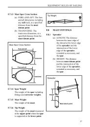
5.33.4 Height of Genoa Halyard (IG):<br />
IG shall be the genoa height measured from the point of attachment of the forestay to the<br />
mast structure, or the intersection of the center line of the forestay with the foreside of the<br />
mast where the point of attachment is internal, to the level of the deck as defined in 5.33.1.<br />
5.33.5 Height of Genoa Halyard Corrected(IGC):<br />
IGC shall be the maximum height to which the head of a jib shall be hoisted. IGC shall be<br />
marked on the front of the mast till the middle of the mast in that section with a contrasting<br />
(white or black) band at a level of 0.450m below IG.<br />
5.33.6 Foretriangle Height (IM):<br />
The formula for the foretriangle height is: IM = (IG+IG*(GO-MW)/(J-GO+MW)) (see 5.33)
TRANSPAC 52 RULE (TP52 RULE)<br />
DRAFT VERSION 6, July 2007<br />
page 14<br />
5.33.7 Forestay Outrigger (GO). GO shall be the horizontal distance from the upper point of<br />
measurement used to determine IG to the after side of the mast or vertical projection of the<br />
after side of the mast.<br />
5.33.8 Height of Spinnaker Halyard (ISP). ISP shall be the height of the uppermost spinnaker<br />
halyard. It shall be measured from the underside of the spinnaker halyard, when drawn<br />
horizontally forward from the mast, to the level of the sheer line abreast the mast as defined<br />
in 5.33.1.<br />
5.33.9 Longitudinal Dimension of Mainmast (MDL1). MDL1 shall be the minimum thickness<br />
of the mast in the longitudinal direction occurring between the deck and the forestay<br />
attachment point.<br />
5.33.10 Transverse Dimension of Mainmast (MDT1). MDT1 shall be the minimum thickness<br />
of the mast in the thwartships direction occurring between the deck and the forestay<br />
attachment point.<br />
5.33.11 Mast Width (MW):<br />
MW is used for calculating IM (see 5.33.5) and shall be the minimum fore and aft width of<br />
the mast to be found at any point below the top of IG and above the lower spreader.<br />
5.33.12 Mainsail Hoist (P):<br />
P shall be the measured length of the hoist of a jib headed mainsail. It is the distance along<br />
the afterside of the mainmast from the highest level to which the head of the sail, or any<br />
part of a headboard carriage abaft the track or mast groove, may be set to the lowest<br />
position of the tack.<br />
The highest point shall be taken as the top of the highest sheave used for the main halyard,<br />
or to the lower edge of a 25mm measurement band. The lowest position of the tack shall be<br />
marked by the upper edge of a 25mm measurement band around the mast from which the<br />
low point of P shall be measured. Usually this band shall be identical in position to the fair<br />
extension of the top of the boom or any external track or groove.<br />
5.33.13 Boom above Sheerline (BAS):<br />
BAS shall be the distance between the low point used in the determination of P and the level<br />
of the sheer at FM, measured with the mast in vertical position.<br />
A) The maximum adjustment downwards (without applying for remeasurement), allowed<br />
from the position of BAS as measured, adjusted when not racing, is 4mm (0.004m).<br />
B) A TP52 shall only be measured with BAS in the position as recorded on the<br />
TP52 Certificate.<br />
C) The mastjack system shall be either not on the boat when racing, or if onboard be<br />
measured with the boat and recorded on the IMS-Certificate Page 2 for position and weight.<br />
Mastram(s) shall never in any way be connected to the yacht’s hydraulic system as used for<br />
sailing functions like headstay adjustment, etc.<br />
5.33.14 Foot of Mainsail (E):<br />
E shall be the length measured along the boom from the aft side of the mast including any<br />
external track or groove, or its fair extension parallel to the axis of the mast, to the aftermost<br />
position to which the sail is permitted to extend. Where this latter point is inside of the<br />
boom end, it shall be located by the inner edge of a 0.025m measurement band around the<br />
boom. Any part of the mast which extends abaft the aft side of the track or mast groove<br />
shall be ignored in determining E.
TRANSPAC 52 RULE (TP52 RULE)<br />
DRAFT VERSION 6, July 2007<br />
page 15<br />
5.33.15 Sheeting Limit (BAL):<br />
BAL shall be the distance from the outer measurement point of E to a contrasting<br />
measurement band denoting the limit on the boom beyond which no lead for the sheeting<br />
of headsails shall be attached. In the absence of such a band BAL shall be measured to the<br />
boom end. BAL shall not exceed 0.152m.<br />
5.33.16 Boom Diameter (BD):<br />
BD shall be the maximum dimension of the main boom measured in section inclusive of any<br />
structure used to stiffen the boom. A boom with a BD in excess of 0.05*E is not permitted.<br />
5.33.17 Chainplate Width (CPW):<br />
CPW shall be the distance between the centers of the bearing points of the chainplates for<br />
the upper shrouds of the mainmast.<br />
5.33.18 Rig Weight and Center of Gravity:<br />
a) The mast, together with standing rigging, shall be weighed and the weight found<br />
recorded as MWT.<br />
b) The vertical center of gravity shall be determined relative to the sheer at FM and recorded<br />
as MCG.<br />
c) As appropriate to the size of the mast, the values for MWT and MCG may be found either<br />
by measurement at the single point of the center of gravity of the mast and rigging or by<br />
measurement of tip and butt weights separately, followed by calculation of the values to be<br />
recorded.<br />
d) All measurements above shall be taken with the components dry and the spars fitted only<br />
with components with which the yacht will actually race as specified below:<br />
A) The mast shall be completely rigged with standing rigging, spreaders, jumpers, lights,<br />
antennae, wiring, luff groove device and all other permanently attached fittings, including<br />
those turnbuckles which are not permitted to be adjusted while racing.<br />
B) Excluded for measurement shall be running rigging, checkstays, rigging adjusters of any<br />
type (hydraulic or otherwise) and any associated blocks and tackle, boom vang and reefing<br />
tackle. Halyard messengers of not more than 4mm diameter and weighing not more than<br />
15 grams per meter and only sufficient for convenient re-leading may be used to replace<br />
internal portions of running rigging.<br />
C) All wiring, messengers and standing rigging shall be in their proper attached positions,<br />
and any slack stretched down and secured along the length of the mast with light material,<br />
such as lanyards or tape, with any tails hanging free at the butt.<br />
D) Headboard, luff slides, spinnaker pole cars and any other adjustable devices shall be at<br />
their lowest limit of travel.<br />
5.33.19 Rigging Plan:<br />
The Sailplan and Mast are to be checked and confirmed by the Measurer to be according the<br />
TP52 Rules and recorded on the TP52 Certificate as follows:<br />
a) Sailplan and Mast: Pass<br />
b) Stroke, forestay adjustment shall be recorded and not be longer than 0.255m: Pass<br />
c). Permanent backstay in place. The permanent backstay and tensioning lay-out shall be<br />
checked by the Measurer to be according to this Rule: Pass<br />
d) No Running Backstays. Fore and Aft Stays Below the Uppermost Backstay are not<br />
allowed under this Rule and their abcense shall be recorded: Pass<br />
e) Halyard locks meet rule: Pass
TRANSPAC 52 RULE (TP52 RULE)<br />
DRAFT VERSION 6, July 2007<br />
page 16<br />
f) Corrector weights may be added to the mast or spreaders. They shall be declared and<br />
their weight and position noted on the certificate.<br />
g) Shims: number/thickness. Total height:...mm.<br />
SAILS<br />
5.34 All sails must be set and trimmed in a manner consistent with the way they are<br />
measured. A sail shall not be constructed in such a manner that any portion may be<br />
completely detached.<br />
5.35 Conflicts may exist between these rules and the Racing Rules of the I.S.A.F. and<br />
National Authorities; in such cases the TP52 Rules will govern, but when not in conflict, the<br />
rules of the I.S.A.F. shall be observed.<br />
5.36 In addition to the prescriptions herein, the measurement instructions and definitions of<br />
TP52 Rules Appendix 3, Sail Measurement, shall apply.<br />
5.37 Measurements of all sails required to be measured must be measured with such<br />
tension between measurement points as will remove all wrinkles across the line of<br />
measurement and must include the fabric length between measurement points.<br />
5.38 Any device or sail construction which, in the opinion of the Measurer, is used to<br />
artificially shorten or lenghten a sail luff for measurement such as, but not limited to, nylon<br />
braid lightly seized to the luff independent of the bolt rope, or twin head attachment points,<br />
is not permitted and shall be removed before measurement.<br />
5.39 Measurement points at the corner of a sail shall be the intersection of the adjacent<br />
sides projected, except in the case of the head of a jib which shall be determined in<br />
accordance with the diagrams below. For jibs other than storm jibs, the head measurement<br />
point is the highest point of the sail. In the case of a storm jib the head measurement point<br />
is the lower of the highest point of the sail or the intersection of the adjacent sides<br />
projected. All other measurement points shall be at the extreme outside of rope, wire or<br />
fabric of the sail's edge.<br />
5.40 Measurement points at the heads of Jibs:<br />
XXXXX<br />
5.41 Measurement and Marking of Sails. All sails shall be available for measuring and those<br />
marked shall include all spinnakers, all mainsails and all jibs. The Measurer shall mark the<br />
sails with a TP52 Class approved stamp (See example below) issued by the TP52 Chief<br />
Measurer, enter the measurements found, sign and date them.<br />
TP52 Sail Stamp<br />
XXXXX<br />
5.42 The dimensions to be recorded are:<br />
Mainsails: HB, MGT, MGU, MGM, MGL, MSW, E (as intended for this sail), Area (see 5.66.d)<br />
Jibs: LP, LP 0<br />
Spinnakers: SLU, SLE, AMG, AST and SPA (see 5.56)
TRANSPAC 52 RULE (TP52 RULE)<br />
DRAFT VERSION 6, July 2007<br />
page 17<br />
5.43 The Measurer shall not apply the TP52 Sail Stamp to any sail which does not comply<br />
with the appropriate definitions and restrictions for that sail as set forth in this paragraph.<br />
5.44 Roach, slab or flattening reefs are permitted along the foot only. Cunningham holes<br />
are permitted.<br />
5.45 Double luffed sails (those with thick or wrap-around luffs, not spinnakers) are not<br />
permitted.<br />
5.46 Sail Inventory:<br />
A yacht while racing shall not carry on board more sails of each type than the numbers set<br />
out below:<br />
Jibs: 6<br />
Masthead jibs: 1 (Coastals/Offshores only)<br />
Light staysails: 2<br />
Spinnakers: 6<br />
Mainsails: 1<br />
Storm Trysails: 1<br />
Storm Jibs: 1<br />
Heavy - Weather Jibs: 1<br />
5.47 Jibs:<br />
Sails in this category, except inner forestaysails and masthead roller furling jibs, must be set<br />
on stays permanently attached to the mast and tacked on the centerline of the yacht. Inner<br />
forestaysails must also be tacked on the centerline of the yacht, but need not be set on a<br />
stay.<br />
5.48 Light Staysails:<br />
Light staysails are those having an LPG less than or equal to 1.1*J which shall only be set<br />
flying.<br />
5.49 Storm and Heavy Weather Sails:<br />
The specifications of storm and heavy weather sails are those of the Offshore Special<br />
Regulations Governing Offshore Racing, section 4.26.4.<br />
Note: a staysail shall not be counted as a heavy weather jib for the purposes of the OSR.<br />
5.50 The race organizer may modify these limitations to the kind(s) and number(s) of sails<br />
appropriate to the character of the race.<br />
5.51 Bloopers are prohibited. When a spinnaker is set, no jib shall be tacked in such a way<br />
as to cause or permit the luff or forward edge of that sail to lie outside of the spinnaker or<br />
spinnaker sheet and, when a spinnaker is set, no sail shall be sheeted to the main boom<br />
except the spinnaker itself.<br />
5.52 Headsails, distinction between Jibs and Spinnakers:<br />
Headsails: The word headsail is defined as a sail set in the foretriangle. It can be either a<br />
spinnaker or a jib.<br />
Distinction between Spinnakers and Jibs: A sail shall not be measured as a spinnaker unless<br />
the mid girth is 75 per cent or more of the foot length.
TRANSPAC 52 RULE (TP52 RULE)<br />
DRAFT VERSION 6, July 2007<br />
page 18<br />
5.53 Definition of Jibs:<br />
A jib is defined as any sail, other than a spinnaker, set in the foretriangle, subject to the<br />
following limitations:<br />
a) A masthead roller furling jib may be carried and used. It shall have a loose luff and tack to<br />
the hull, deck, spinnaker pole or sprit.<br />
b) A fractional working jib may be carried and used.<br />
c) Jibs shall be measured as specified in TP52 Rule 5.53, 5.54, and 5.55.<br />
d) No jib shall have jib roach.<br />
e) The head of a jib shall not be greater than 0.10m, when measured perpendicular from the<br />
luff, projected if needed at the jibs highest point, to the leach, projected if needed.<br />
f) In any jib the mid girth measured between the mid point of the leech and the nearest point<br />
on the luff shall not exceed 50 per cent of the LPG nor shall the length of intermediate girth<br />
at 25 per cent and 75 per cent of the leech from the head exceed values similarly<br />
proportional to their distance from the head.<br />
ALTERNATIVE:<br />
f) In any jib the upper girth measured at .....m, the midgirth measured at ....m, and<br />
the lowergirth measured at ....m from the aft head point along the leach, to the<br />
nearest point on the luff shallnot exceed in the same order......m, .......m and<br />
.....m. Nor shall the intermediate values be proportionally above the given values.<br />
g) The distance, measured on the surface of the sail, between the midpoint of the foot and<br />
the midpoint of the luff shall not exceed 0.55% of the length of the leech.<br />
h) No clewboards may be used in jibs.<br />
i) No headboards may be used in jibs.<br />
j) Battens may be used in jibs only if the number of battens is limited to 4, which must be<br />
arranged with approximately equal spacing between head and clew (see also 9.8.1.d).<br />
k) A yacht may use a luff groove device provided that such luff groove device is not made of<br />
carbon fibre and of constant section throughout its length and is either essentially circular in<br />
section or is free to rotate without restraint. Any permitted device on the forestay other than<br />
hanks shall be measured for FSP (see 5.55).<br />
l) Jibs may be sheeted from only one point on the sail except in the process of reefing the<br />
sail. (Thus quadri-lateral or similar sails or sails in which the sailcloth does not extend to the<br />
cringle at each corner are excluded.)<br />
m) Aromatic polyamides, carbon fibres and other high modulous fibres shall not be used in<br />
the storm jib.<br />
5.54 Measuring: Longest Perpendicular of Jibs (LPG and LPG0):<br />
a) Jibs shall be measured on the perpendicular from the luff (outside edge of the sail and/or<br />
luff rope) to clew (intersection of the lines of the foot and leech).<br />
b) LP shown on the rating certificate shall be the largest such dimension found on the jibs<br />
carried on the yacht plus FSP, so LP = LPG + FSP.<br />
c) LP0 shown on the rating certificate shall be the dimension found on the Masthead Luff Jib<br />
carried on the yacht, so LP0 = LPG<br />
5.55 Measuring: Forestay Perpendicular (FSP):<br />
FSP is twice the maximum dimension, measured at right angles to the longitudinal axis, of a<br />
luff groove device.<br />
5.56 Definition of Spinnakers:<br />
a) Spinnakers may be Symmetrical or Asymmetrical and the area shall be measured by the<br />
following formula:<br />
Spinnaker Area = (SLU + SLE) * SF/4 + (SMG - SF/2) * (SLU + SLE)/ 3<br />
b) No spinnaker may have a mid girth of less than 75% of the foot length.<br />
c) Battens shall not be used in spinnakers.<br />
d) Adjustable leech lines are not permitted in symmetric spinnakers.
TRANSPAC 52 RULE (TP52 RULE)<br />
DRAFT VERSION 6, July 2007<br />
page 19<br />
NOTE: TP52 Bylaws VIII B1: No symmetrical spinnakers allowed in buoy racing.<br />
5.57 A symmetric spinnaker has the following characteristics:<br />
a) The luff and leech must be of equal length.<br />
b) The sail must be symmetric, in shape, material and cut, about a line joining the head to<br />
the center of the foot.<br />
5.58 An asymmetric spinnaker has the following characteristics:<br />
The luff shall be at least 5 percent longer than the leech (see 5.62.b ).<br />
5.59 Measurement of Spinnakers:<br />
Spinnakers shall be measured with such tension as will remove all wrinkles across the line<br />
of measurement. Adjustable leech lines are not permitted in symmetric spinnakers and battens<br />
are not permitted in any spinnaker.<br />
5.60 Spinnaker Headboard (HBS):<br />
HBS shall be the maximum width of a spinnaker headboard, which shall not exceed 0.05*J.<br />
5.61 Spinnaker Maximum Width (SMW):<br />
SMW for a symmetric spinnaker shall be the spinnaker maximum width, whether at the foot<br />
or across the body of the sail between points on the luff and leech equidistant from the<br />
head.<br />
5.62 Spinnaker Luff and Leech (SLU and SLE):<br />
a) SLU and SLE shall be the greatest length of a symmetric spinnaker luff and leech measured<br />
along the edges of the sail from head to foot.<br />
For symmetric spinnakers, where stiffening is used to widen the angles at the tack and clew<br />
beyond an included angle of 110 degrees the greatest length of any such stiffening along<br />
the foot, measured from the clew, shall be added to the luff length to determine SLU + SLE.<br />
b) Asymmetric Spinnaker Luff (SLU) and Leech (SLE):<br />
i) SLU shall be the length of the longer edge (luff) of an asymmetric spinnaker measured<br />
along the edge of the sail from head to tack.<br />
ii) SLE shall be the length of the shorter edge (leech) of an asymmetric spinnaker measured<br />
along the edge of the sail from head to clew.<br />
5.63 Spinnaker Foot Length (SF):<br />
Spinnaker foot length shall be the distance from tack to clew measured in the shortest path<br />
on the surface of the sail.<br />
5.64 Spinnaker Mid Girth Length (SMG):<br />
The recorded measurement on which a spinnaker area is calculated shall be SMG. SMG<br />
shall be the distance between the midpoints of luff and leech measured in the shortest path<br />
on the surface of the sail.<br />
5.65 For calculation of sail area the dimensions of SMG, SF, SLU and SLE shall be the<br />
largest of such dimensions found on any of the spinnakers carried on the yacht.<br />
5.66 MAINSAIL:<br />
a) Mainsail battens shall be unlimited in length, number or location.<br />
b) No device other than a normal leech line shall be employed to adjust the curvature of any<br />
mainsail batten.<br />
c) The mainsail may be reefed, but may not be lowered solely for the purpose of tacking or<br />
jibing.
TRANSPAC 52 RULE (TP52 RULE)<br />
DRAFT VERSION 6, July 2007<br />
page 20<br />
d) The mainsail area formula:<br />
MSA=P/4*(E+MGL)/2)+(P/4*(MGL+MGM)/2)+(P/4*(MGM+MGU)/2)+(P/8*(MGU+MGT)/2)+<br />
(P/8*(MGT+HB)/2)<br />
5.67 Mainsail Headboard (HB):<br />
HB shall be the maximum fore and aft dimension from the luff of the mainsail, projected if<br />
necessary, to the extreme aft edge of the leech measured across the widest part of the<br />
head. If the widest point of the head is in doubt, the highest of the widest points shall be<br />
used. If no headboard is fitted, then HB shall be the dimension taken perpendicular to the<br />
luff of the mainsail, or its fair projection, to the extreme aft edge of the leech, or its fair projection,<br />
across the bearing surface of the head cringle or strop.<br />
5.68 Mainsail Girths (MGT, MGU, MGM, & MGL):<br />
MGT, MGU, MGM and MGL shall be the length of the girths of the mainsail taken at points<br />
7/8, 3/4, 1/2 and 1/4 of the leech from the clew respectively, measured in accordance with<br />
Appendix 3. The values for MGT, MGU, MGM and MGL shall be recorded for each mainsail<br />
used on the yacht.
TRANSPAC 52 RULE (TP52 RULE)<br />
DRAFT VERSION 6, July 2007<br />
page 21<br />
PART 6 - ACCOMMODATION<br />
6.1 Purpose:<br />
The purpose of these requirements is to insure that all yachts racing under the TP52 Rule<br />
meet minimum standards of accommodation in order to provide for equal opportunities<br />
racing, reasonable comfort of crews and safe stowage of gear.<br />
6.2 Compliance:<br />
A yacht shall not race unless she complies with all the accomodation requirements.<br />
6.3 Acknowledging that it is difficult to cover every condition and innovation, designers,<br />
builders and owners carry the responsibility for complying with the intent and spirit of the<br />
TP52 Accommodation Rules.<br />
6.4 A standard Accommodation Compliance Form may be provided for certifying<br />
compliance. Where compliance has been documented to the satisfaction of the TP52<br />
Measurer, the TP52 Certificate shall bear the notation “ Pass” to that effect.<br />
6.5 A yacht’s compliance with the Accommodation Rules may be challenged by a<br />
competitor, a race organizing authority or the TP52 Measurers and TP52 Management.<br />
In the event of such a challenge, the authority shall render a decision in accordance with the<br />
fundamental requirements, the detailed requirements and the expressed intent of the<br />
Accommodation Rules. Nominal compliance with words and numbers but not with<br />
substance shall not be recognized as acceptable compliance.<br />
6.6 Fundamental Requirements and Definitions:<br />
All systems relating to living, eating, sleeping, and stowage specified in these regulations<br />
shall be arranged in a manner suitable for use at sea and shall operate so as to provide the<br />
service function normally associated with the system.<br />
Items shall be presented as they are intended to be used. For example, any item intended<br />
for use as a berth shall be in place and its function declared at the time of inspection.<br />
6.7 Designations such as berth, sink, stove, and so forth are intended to define the full utility<br />
of conventional equipment and whatever weight is customarily associated with it.<br />
6.8 Designations such as locker, bin and drawer, specify fabric "soft bins" or rigid<br />
construction and full practicality for convenient and safe segregated stowage usable and<br />
accessible under offshore conditions. The contents of all compartments shall be fully<br />
secured by doors or other suitable devices.<br />
6.9 “Permanently Installed” means the items are built in and may not be removed from<br />
their permanently installed position for or during racing.<br />
6.10 In reference to any requirements for berths or settees, “hard bottom type” means built<br />
in, rigid and paneled construction which supports a hard-bottomed berth or settee when in<br />
its horizontal position.<br />
6.11 Interior Volume:<br />
Compliance with the provisions for Interior Volume is required.<br />
The purpose of this requirement is to define an interior volume which is appropriate to the<br />
size of the yacht and which allows the arrangement of interior accommodations suitable for<br />
offshore racing.
TRANSPAC 52 RULE (TP52 RULE)<br />
DRAFT VERSION 6, July 2007<br />
page 22<br />
6.11.1 Interior Height:<br />
Interior Height (IH) shall be 2.13m from the deepest fairbody section at the inside of the hull<br />
surface. Note that this level is independent of the actual height of the cabin sole.<br />
6.11.2 Overhead Area at Full Interior Height: At IH there shall exist under the overhead a<br />
plane of length not less than 2.15m and area not less than 1.23 m2, ignoring deck beams<br />
and deck stringers. The aft extent of this area at the centerline shall lie not forward of a point<br />
located 8.72m aft of the stem.<br />
6.11.3 Overhead Area at 90% Interior Height: At a height of 1.93m there shall exist under<br />
the overhead a plane of length not less than 3.58m and minimum area of 5,32m2.<br />
For a length of 2,86m, found parallel to the centerline of the yacht, the outboard width of<br />
this plane shall be not less than 1.50m. Deck beams and deck stringers may be ignored.<br />
6.11.4 The Overhead Area at 100% and at 90% height may have local intrusions. IH shall<br />
give the crew a safe working area while below decks.<br />
There shall be a box with a minimum lenght of 2.86m and minimum width of 1.50m, corners<br />
of the box shall lie under the overhead. The combined area of the intrusions into the box<br />
shal be not greater than 0.13m2.<br />
From 90% IH to local deck level, the combined intrusions area shall not be greater than<br />
0.13m2, measured in the IH plane. Deck beams and stringers might be ignored, except when<br />
intrusions are shielded by deckbeams or stringers, then the extrusion is not exempted from<br />
the loss of area. Additional measurements may be needed to calculate the area or loss of<br />
area as described in this rule.<br />
6.12 Cabin Sole:<br />
Cabin soles shall extend fore and aft over a length which provides convenient access to<br />
lockers, berths, galley, head, navigation area and other components making up the yacht’s<br />
interior. Cabin soles may be discontinuous in height and interrupted in way of ring frames<br />
or other structural members.<br />
6.12.1 The sole shall extend transversely to the inner skin of the hull or vertical faces of<br />
berth fronts, lockers or partitions.<br />
6.12.3 The cabin sole shall be a structure independent of the inner skin of the hull. It may be<br />
of any permitted material provided it exhibits similar strength and stiffness characteristics to<br />
that of solid wood cabin soles when installed in accordance with good yacht practice.<br />
6.12.4 The cabin sole is not required forward of the mast.<br />
6.13 Berths:<br />
Minimum number of berths qualifying under this rule shall be 4. At least 2 of those shall be<br />
of the hard bottom type.<br />
6.13.1 Each berth shall be at least 1.9m in length measured to the inside of any structure of<br />
the berth, bulkheads or partitions encompassing the berth. The minimum width measured<br />
in a similar manner to length at the top surface of the mattress shall be 0.6m measured at<br />
1/4 of the berth length.<br />
6.13.2 A double berth shall be qualified as a single berth.<br />
6.13.3 The foot and head ends of berths may taper as required by the hull shape.<br />
6.13.4 With all berths in the horizontal position the minimum clearance above any mattress<br />
at the centerline over half of the length of the berth shall not be less than 0.5m.
TRANSPAC 52 RULE (TP52 RULE)<br />
DRAFT VERSION 6, July 2007<br />
page 23<br />
6.13.5 Mattresses of a size covering the entire surface shall be fitted to all berths; they shall<br />
be of a thickness not less than 0.03m for soft bottom berths. For hard bottom berths the<br />
minimum thickness shall be 0.1m. Minimum mattress density shall be 8kg/m3.<br />
6.13.6 The minimum height of the bottom of any hard berth (excluding the mattress) shall<br />
be 0.30m above the cabin sole.<br />
6.14 Personal Gear Stowage:<br />
Minimum volume of personal gear stowage to qualify under this rule shall be 0.22m3.<br />
6.14.1 Stowage for personal gear (clothing, toiletries and miscellaneous articles) shall be<br />
provided in the form of fabric "soft bins" or built in rigid lockers with doors or other suitable<br />
devices, bins with hatches, and drawers. Bilge areas located below the cabin sole and<br />
hanging locker volume (see 6.18 below) shall not be included when measuring space for this<br />
stowage requirement. Space under berths shall not be counted except space in the form of<br />
fitted drawers which may comprise not more than 30% of the qualifying total volume.<br />
6.15 Galley: All stoves must be gimbaled or fitted with high retaining rails to permit their<br />
safe operation underway. A yacht shall have a stove with at least 3 burners. An oven with its<br />
own burner or a microwave counts as one burner. To count as a burner, a microwave shall<br />
have a sufficient source of power at all times including extended passages at sea.<br />
6.15.1 Sinks: A sink shall be permanently installed and fitted with a drainage system which<br />
permits use underway and of size in keeping with the accommodations of the yacht.<br />
6.15.2 Galley Gear Stowage: Seaworthy stowage shall be provided, segregated for a normal<br />
complement of cooking utensils, cutlery, glasses, dishes, etc.<br />
6.15.3 Food Stowage: To qualify, stowage for food shall be provided in rigid lockers, bins,<br />
or other suitable compartments. Spaces below the cabin sole shall not be considered as<br />
meeting the requirements. Minimum volume of food stowage to qualify under this rule shall<br />
be 0.32m3.<br />
6.16 Head Compartment:<br />
The head compartment shall be constructed in such a manner as to be totally separated<br />
from the main cabin by rigid partitions and one rigid or canvas door when in use. The door<br />
opening shall not be wider than 1.0m, measured in any horizontal direction. There shall be<br />
sufficient space and clearances within the head compartment with the door shut to permit<br />
crew to sit, stand, and turn around.<br />
6.16.1 Toilet: Approved type permanently installed and operable in compliance with local<br />
regulations pertaining to Marine Sanitation Devices and their use. The toilet shall be of a<br />
type plumbed for the intake of seawater.<br />
6.16.2 Wash Basin: A wash basin shall be permanently installed. It may be fixed, folding or<br />
sliding and shall be fitted with a drainage system which permits use underway.<br />
6.16.3 Separate Discharge: Sinks and wash basins shall be fitted with separate discharge<br />
and not discharge through the toilet system. All seacocks shall be maintained as operational<br />
while racing.<br />
6.17 Navigation Table:<br />
A flat area suitable for chart work shall be required. The navigation table or area shall be<br />
built with storage for charts, navigational instruments, books, etc.
TRANSPAC 52 RULE (TP52 RULE)<br />
DRAFT VERSION 6, July 2007<br />
page 24<br />
6.18 Fresh Water Capacity:<br />
Minimum fresh water capacity shall be 160 litres.<br />
6.18.1 Fresh water pumps shall be installed at the sink and wash basin and fresh water shall<br />
be contained in permanently installed tankage either of rigid construction or of the bladder<br />
type.<br />
6.19 Fuel Capacity:<br />
Minimum fuel (diesel) capacity shall be 83 litres.<br />
6.19.1 The engine shall be directly supplied from permanently installed fuel tankage.
TRANSPAC 52 RULE (TP52 RULE)<br />
DRAFT VERSION 6, July 2007<br />
page 25<br />
PART 7 - PERMITTED MATERIALS & CONSTRUCTION<br />
7.1 Any questions regarding the application of this regulation shall be referred to the<br />
TP52 Chief Measurer or TP52 Class Manager. The limitations apply also to modifications.<br />
7.2 Hull and deck structure and appendages, internals and interior joiner work, the<br />
Permitted Materials are :<br />
Wood, natural fibers and un-reinforced plastic. Plastic reinforced with fiber of any of the<br />
following materials: glass, aramid, polyester, polyamide, polyethylene and natural fiber.<br />
Iron, steel, lead, copper and their alloys; bronze, brass, monel and aluminum of the 5000<br />
and 6000 series. High Strength Carbon (HSC) (see Notes:a below for definition)<br />
7.3 Core material only of wood or plastic foam of nominal density not less than 70 kg/ m3.<br />
7.4 Aramid paper honeycomb core material of minimum nominal density 48kg/m3 in the<br />
hull and deck structure.<br />
7.5 Restrictions, requirements and remarks:<br />
a) Restrictions related to FRP construction: Curing temperature and pressure limits apply.<br />
Externally applied heat shall not be greater than 80oC. Externally applied pressure shall not<br />
be greater than the ambient atmospheric pressure of the vacuum bag method.<br />
b) Exterior hatches may be of the same material as the deck. Chainplates may be of the<br />
same material as the surrounding deck, but must be included in any required plan approval.<br />
c) Cores of wood, plastic foam or other forms of non-metallic honeycomb irrespective of<br />
compliance with a minimum density requirement are permitted for internals and interior<br />
joinery work.<br />
d) The maximum allowable cure temperature in association with honeycomb construction is<br />
105°C. Externally applied pressure shall not be greater than the ambient atmospheric<br />
pressure of the vacuumbag method.<br />
e) Hull Skin Construction Limits shall apply *(see 7.6 below). Owners are reminded of their<br />
responsibility under TP52 Rule 9.3.4<br />
f) Rudders/rudder stocks. All permitted materials, including HSC. Restrictions related to FRP<br />
construction do not apply. Core materials of any density can be used.<br />
g) Steering systems, incl. steering quadrants, pedestals, wheels and tillers. All permitted<br />
materials, including HSC.<br />
h) Sail battens, deck and spar fittings, chain plates. All permitted materials including HSC.<br />
Core materials of any density can be used.<br />
Chain plates may be of the same material as the surrounding deck, but must be included in<br />
any required plan approval.<br />
i) Winch drums, spindles and gears. All permitted materials excluding HSC. Carbon winch<br />
drums are not permitted.<br />
j) Mainsail headboards, sail hardware. All permitted materials excluding HSC.<br />
k) Walls of booms, spinnakerpoles and reaching struts. All permitted materials including<br />
HSC. Restrictions related to FRP construction do not apply.<br />
l) Masts (and integral moldings, such as tangs), spreaders and jumper struts.<br />
Aluminum alloys, steel alloys or fiberglass reinforced plastic, carbon fiber having a maximum<br />
fiber modulus of 400GPa, glass fiber.<br />
Any addition of material to the base mast section shall consist of the same primary<br />
structural material as the mast itself. Restrictions related to FRP construction apply.<br />
Masts shall not be of sandwich construction. Mast construction is considered as “sandwich”<br />
where in any point of the structure there is a core of lighter materials between the fiber<br />
layers, the thickness of which exceeds the total thickness of the fiber reinforced laminate<br />
walls or the density of which is less than 300 kg/m3. Any addition of material to the base<br />
mast section shall consist of the same primary structural material as the mast of itself.
TRANSPAC 52 RULE (TP52 RULE)<br />
DRAFT VERSION 6, July 2007<br />
page 26<br />
m) Standing rigging which by the TP52 Rule is not allowed to be adjusted while racing.<br />
Steel wire and steel rod and circular of shape.<br />
7.6 Hull Skin Construction Limits:<br />
Resistance of Hulls to Local Impact. To limit damage from local impact, no yacht of fibre<br />
reinforced plastic sandwich hull construction shall race under the TP52 Rule if the outer hull<br />
skin contains a reinforcement weight less than that given below:<br />
a) E-Glass Reinforcement with Epoxy, Polyester or Vinylester Resin:<br />
Ws = 1802 g/m2<br />
b) S- or R-Glass Reinforcement with Epoxy or Vinylester Resin: Ws = 1554 g/m2<br />
c) Kevlar Reinforced with Epoxy or Vinylester Resin: Ws = 1015 g/m2<br />
d) High Strength Carbon Fiber Reinforcement with Epoxy or Vinylester Resin:<br />
Ws = 1227 g/m2<br />
Ws = minimum required weight of reinforcement in g/m2.<br />
Notes:<br />
a) High Strength Carbon Fibre is defined as having a maximum fiber modulus of 250GPa<br />
(36,250,000 psi) and minimum tensile strain at failure of 1.4%.<br />
b) For hybrid laminates, weight is to be determined on percentage volume of each different<br />
reinforcing material in terms of total reinforcing volume.<br />
c) Core material density shall not be less than 70 kg/m3, except in the case of honeycomb<br />
core material where permitted, then material density shall not be less than 48 kg/m3.<br />
d) Polyethylene, polyester and natural fibres shall not count toward fibre reinforcement<br />
weight. Also, the number of plies in the outer hull skin is to be no less than 4 for all types of<br />
reinforcement. A ply must have a minimum weight of 175 g/m2.
TRANSPAC 52 RULE (TP52 RULE)<br />
DRAFT VERSION 6, July 2007<br />
page 27<br />
PART 8 - ENGINE AND PROPELLER INSTALLATION<br />
8.1 Each yacht must have a properly installed Yanmar inboard water-cooled diesel engine,<br />
oriented fore and aft and located on centreline connected to a Yanmar sail drive with<br />
2-bladed folding propeller. Permitted Yanmar engine and sail drives are listed below.<br />
The Yanmar engine and Yanmar saildrive may be installed in either the “Z” or “C”<br />
configuration and shall be otherwise installed in their complete production configuration<br />
without modification, including specifically fairing over the cooling water intakes.<br />
8.2 The Engine Weight (EW) shall be the manufacturers weight as mentioned in the<br />
manufacturers manual for the engine. The minimum EW is 233kg.<br />
8.3 The propeller installation shall not have an EDL (Strut Drive Length) of less than 1.50 x<br />
PRD (Propeller Diameter). EDL is defined as the distance from the center of the propeller<br />
along the propeller axis to the trailing edge of the keel.<br />
8.4 Engines and Sail drives shall be installed such that they do not reduce keel bolt access<br />
nor do they interfere with the structure of the keel attachment.<br />
8.5 The sail drive installation shall have a PIPA of not less than 0.0036m2, using the<br />
following formula:<br />
PIPA = 0.06 x ST1 x (ST5 – 0.5 x ST4) + 0.4 x (0.8 x ST4)^2<br />
• ST 1 Minimum Projected Strut Thickness<br />
• ST 4 Strut Drive Hub Diameter<br />
• ST 5 Strut Drive Clearance<br />
8.6 Permitted Yanmar Engine & Saildrive combinations include:<br />
Yanmar 4JH2CE x SD31, Yanmar 4JH3CE1 x SD40, Yanmar 4JH4CE X SD40,<br />
Yanmar 4JH3-TCE x SD40T, Yanmar 4JH4CE X SD50<br />
As these models are replaced other combinations will be added.<br />
8.7 General Requirements:<br />
The propeller shall at all times be ready for use and shall not be retracted, housed or<br />
shielded except by a conventional strut or aperture.<br />
8.8 Propeller Type:<br />
Folding Propeller. To qualify as "folding" propeller shall have a minimum of two blades that<br />
fold together pivoting on an axis at right angles to the shaft line when not being used for<br />
propulsion.<br />
8.9 Installation Type:<br />
Strut Drive. To qualify as "strut drive" the drive train shall be enclosed in a strut and the unit<br />
incorporating drive train and strut shall be of a standard Yanmar model in series production<br />
(see 8.6).<br />
8.9.1 Strut Drive Length (EDL). EDL shall be the distance, measured along and in<br />
prolongation of the propeller shaft, from the center of the propeller (the intersection of the<br />
blade axis and shaft) to the aft edge of any other strut or fin (except the rudder blade)<br />
forward of the propeller. If any fairing or fin extension lies between the forward profile of<br />
the strut drive as manufactured and the forward measurement point of EDL, the advice of<br />
the TP52 Chief Measurer shall be sought.<br />
8.9.2 ST1. ST1 shall be the minimum projected thickness of the strut at any point between<br />
the hull and the shaft line.
TRANSPAC 52 RULE (TP52 RULE)<br />
DRAFT VERSION 6, July 2007<br />
page 28<br />
8.9.3 ST2. ST2 shall be the minimum width of the strut, (including the strut hub) measured<br />
parallel to the shaft.<br />
8.9.4 Strut Drive Hub Diameter (ST4). ST4 shall be the smallest dimension through the shaft<br />
centerline of the projected area of the drive hub at its interface with the propeller hub.<br />
8.9.5 Strut Drive Clearance (ST5). ST5 shall be the distance, measured perpendicular to the<br />
propeller shaft at the forward end of ST2, from the centerline of the shaft to the hull, or fair<br />
continuation of the hull.<br />
==========================================================================<br />
ALTERNATIVE FOR ENGINE AND PROPELLER INSTALLATION:<br />
PART 8 - ENGINE AND PROPELLER INSTALLATION<br />
8.1 Each yacht must have a properly installed Yanmar inboard water-cooled diesel engine,<br />
oriented fore and aft and located on centreline, connected to a standard Yanmar sail drive<br />
with a 2-bladed folding propeller. Permitted Yanmar engine and sail drives are listed in 8.5.<br />
The Yanmar engine and Yanmar saildrive may be installed in either the “Z” or “C”<br />
configuration and shall be otherwise installed in their complete production configuration<br />
without modification, including specifically fairing over the cooling water intakes.<br />
8.2 The Engine Weight (EW) shall be the manufacturers weight as mentioned in the<br />
manufacturers manual for the engine. The minimum EW is 233kg.<br />
8.3 The propeller installation shall not have an EDL of less than 0.600m. EDL is defined as<br />
the distance from the center of the propeller (the intersection of the blade axis and shaft)<br />
along the propeller axis to the trailing edge of the keel.<br />
8.4 Engines and Sail drives shall be installed such that they do not reduce keel bolt access<br />
nor do they interfere with the structure of the keel attachment.<br />
8.5 Permitted Yanmar Engine & Saildrive combinations include:<br />
Yanmar 4JH2CE x SD31, Yanmar 4JH3CE1 x SD40, Yanmar 4JH4CE X SD40,<br />
Yanmar 4JH3-TCE x SD40T, Yanmar 4JH4CE X SD50<br />
As these models are replaced other combinations will be added.<br />
8.6 General Requirements:<br />
The propeller shall at all times be ready for use and shall not be retracted or shielded except<br />
by the standard strut.<br />
8.7 Propeller Type:<br />
Folding Propeller. To qualify as "folding" a propeller shall have a minimum of two blades<br />
that fold together pivoting on an axis at right angles to the shaft line when not being used<br />
for propulsion. PRD (Propellor Diameter) shall not be less than 0.400 m.<br />
8.8 Strut Drive Clearance (ST5). ST5 shall be the distance, measured perpendicular to the<br />
propeller shaft at the forward end of the strut, from the centerline of the shaft to the hull, or<br />
fair continuation of the hull. ST5 shall not be less than 0.260m.<br />
==========================================================================
TRANSPAC 52 RULE (TP52 RULE)<br />
DRAFT VERSION 6, July 2007<br />
page 29<br />
PART 9 - OWNER'S RESPONSIBILITIES<br />
9.1 Owner’s Signature:<br />
Before a TP52 Certificate is valid it must be signed by the Owner of the yacht. The name of<br />
the individual who signs the TP52 Certificate shall also be printed on the Certificate. By this<br />
signature the Owner signifies that he or she understands the Owner’s responsibilities under<br />
all parts of the TP52 Rule, a copy of which shall be aboard while racing.<br />
9.2 Responsibility for Compliance:<br />
The Owner shall have the primary responsibility for ensuring compliance with the TP52<br />
Rules. When the person in charge of the yacht while racing is not the Owner, he shall be<br />
equally responsible for compliance.<br />
Owner's responsibilities are divided into three categories:<br />
• Owner's responsibilities prior to and during measurement.<br />
• Owner's responsibilities after measurement.<br />
• Owner's responsibilities whilst racing.<br />
9.3 Owner's Responsibilities, Measurement:<br />
The Owner is responsible for arranging measurement with the TP52 Measurers.<br />
9.3.1 Measurement Ashore:<br />
a) He shall present the TP52 for measurement ashore in an accessible location, clear of<br />
obstructions, properly chocked and leveled (see 4.1 for details).<br />
b) From 1-10-2007 the TP52 Class will require each new boat to be fully measured, in other<br />
words using hullfiles of boats from the same mould or plug will not be allowed, whether the<br />
mould or plug was build before or after that date.<br />
9.3.2 Measurement Afloat:<br />
a) He shall on another occasion make the yacht available at a suitable location agreed with<br />
the Measurer so that flotation measurements may be taken.<br />
b) He is responsible for preparing the yacht in measurement trim as specified in 4.2.2.<br />
He shall declare to the Measurer the weight and location of all ballast, except that contained<br />
in the external keel, and all other items mentioned in 4.2.3(i). He shall, together with the<br />
Measurer, complete and initial the Measurement Inventory and Check List (See Appendix 2).<br />
c) If the yacht has portable tanks he shall declare their size and intended location.<br />
9.3.3 Sail Areas:<br />
He is responsible for declaring to the Measurer all spars and sails that he proposes to carry<br />
on the yacht and the location in which he proposes to set them, so that they may be<br />
properly measured.<br />
9.3.4 Hull Construction and Spar Material:<br />
He is responsible for declaring to the measurer the type of hull construction and material of<br />
which the hull and spars are built.<br />
9.4 Owner's Responsibilities after Measurement:<br />
It is the Owner's responsibility to declare to the TP52 Chief Measurer any changes made to<br />
the yacht, its rig, or its equipment which could change any of its measurements under the<br />
rule. Such changes could be:
TRANSPAC 52 RULE (TP52 RULE)<br />
DRAFT VERSION 6, July 2007<br />
page 30<br />
a) Changes of ballast in amount or location or configuration.<br />
b) Change of tankage, fixed or portable, in size or location.<br />
c) Any changes in the engine and/or propeller installation.<br />
d) Addition, removal or change of location of gear or equipment, or structural alteration to<br />
the hull, that affect the trim or flotation of the yacht.<br />
e) Movement of any measurement bands used in sail area measurement, or any changes in<br />
spars, spar location (see for limits 5.33.12 and 9.7.1) or headstay position.<br />
f) The Owner shall be responsible for ensuring that all mainsails, all spinnakers, and all jibs<br />
bear the official TP52 Sail Stamp and are marked by the Measurer as required under 5.42.<br />
He shall also be responsible for ensuring that the sails and these marked dimensions do not<br />
contravene the values stated or permitted for them on the TP52 Certificate.<br />
h) Changes to spars or standing rigging configuration, including elements of rigging<br />
identified as adjustable while racing.<br />
i) Changes to the Elements determing the VCG (Vertical Centre of Gravity) including hull,<br />
deck and appendage construction, spars, accommodation and rig configuration, etc.<br />
9.5 Owner's Responsibilities while Racing:<br />
The Owner is responsible for ensuring that the TP52 Rule, Bylaws and Interpretations are<br />
aboard the yacht and that all members of the crew fully understand and comply with the<br />
limitations which apply whilst racing.<br />
9.6 Sails shall only be set in those areas declared for measurement, and no sail shall be<br />
carried on board that exceeds the limiting dimensions for such a sail as shown on the TP52<br />
Certificate, nor is of a shape or has features not permitted by the Rule.<br />
9.7 Restrictions on Masts:<br />
9.7.1 Movement of mast at deck and step:<br />
Altering the location of the mast at the step or deck whilst racing is not permitted. However,<br />
a natural movement of the mast at the deck not exceeding 10 per cent of the greatest fore<br />
and aft or transverse dimension of the mast at that point is permitted, as long as J is<br />
respected at all times. To this purpose movement of the mast shall be adequately restricted<br />
to not allow the mast to move aft of J Max = 6.188m at any time.<br />
Whilst not racing the limits of movement without requiring remeasurement are:<br />
A) At decklevel, restrictions as set by J.<br />
B) At the step restrictions as set by 5.33.12 and along the centreline (fwd/aft movement) of<br />
plus or minus 0.015m from the point as measured with.<br />
9.7.2 Adjustment of Rigging:<br />
Adjustment of rigging whilst racing is not permitted except as specifically set forth below.<br />
Otherwise all means of adjustment must be positively locked and/or bound up to prevent<br />
accidental adjustment whilst racing. The following adjustment is permitted while racing<br />
except where an element of rigging has been declared not adjustable for rating purposes:<br />
a) For purposes of safety, i.e. an exceptional adjustment of a stay to cure a fault.<br />
b) The forestay length may also be adjusted a maximum of 0.255 meters while racing.<br />
c) Inner forestays attached to the foremost mast between 0.225*IG and 0.75*IG above the<br />
sheerline.<br />
d) Permanent backstay.
TRANSPAC 52 RULE (TP52 RULE)<br />
DRAFT VERSION 6, July 2007<br />
page 31<br />
9.8 Restrictions on setting and Sheeting of Jibs:<br />
9.8.1 Tack Points of Jibs:<br />
a) When a jib is set under a spinnaker or inside another jib, it shall not be tacked in such a<br />
position that, if the sail were trimmed flat along a parallel to the center line of the yacht, its<br />
clew would fall abaft the LP line (see b below).<br />
b) The LP line is defined as a line abaft and parallel to the foremost headstay and separated<br />
from it by the dimension of LP printed on the TP52 Certificate. The foremost headstay is<br />
defined as the line joining the upper measurement point of IG and the forward measurement<br />
point of J.<br />
c) No tack pennant greater than 0.76m may be used on a jib when set flying.<br />
d) No jib shall be so tacked that the forward end of any batten is aft of the center line of the<br />
mast.<br />
9.8.2 Sheeting of Jibs:<br />
Jibs may be sheeted to any part of the deck or rail, but to no fixed point higher than 0.22m<br />
above the deck or coachroof, or to the main boom, within the measurement limits (see<br />
5.33.14) or to the spinnaker pole when the pole is set on the opposite side from the main<br />
boom but may not be sheeted to any other spar or outrigger.<br />
9.8.3 No jib may be set in conjunction with any other headsail so as by any means to<br />
simulate a double clewed or double luffed jib. (For example, except when changing sails, no<br />
two jibs may be carried simultaneously in a luff groove device and sheeted on the same side<br />
of the yacht.)<br />
9.9 Restrictions on Setting and Sheeting of Spinnakers:<br />
9.9.1 Setting of spinnakers:<br />
a) Spinnaker Pole. A spinnaker pole shall only be used with its inboard end attached to the<br />
mast.<br />
b) Notwithstanding failure to meet the definition of a spinnaker (see 5.56) a bona fide jib<br />
(see 5.53) for which the yacht has been measured may be set and sheeted as a spinnaker<br />
where either of the following conditions apply:<br />
i) In heavy weather when no other sail is set in the foretriangle and the apparent wind is<br />
abaft the beam or<br />
ii) When all spinnakers aboard have been damaged beyond repair during the race. A jib so<br />
set may have either its tack or clew to the spinnaker pole.<br />
9.9.2 Sheeting of Spinnakers:<br />
a) Spinnakers shall be sheeted from only one point on the sail.<br />
b) A spinnaker may be sheeted to any part of the rail or deck or to the main boom, within<br />
the measurement limits (see 5.33.14), but to no other spar or outrigger.<br />
c) Struts, spools or similar devices used solely for the purpose of keeping the spinnaker guy<br />
away from the windward main or foremast shrouds are permitted but are not to be used for<br />
any other purpose.<br />
9.10 Restrictions on Setting and Sheeting of Mainsails:<br />
Mainsails shall be either fully secured at the foot or fully loose footed and shall remain so<br />
whilst racing. A mainsail secured at the foot shall be provided with a bolt rope, track or<br />
tunnel slides, or similar boom attachment that prevents the foot from lifting away from the<br />
boom. A loose-footed mainsail shall be sheeted only from a single clew.<br />
9.10.1 Spare Mainsails are not permitted to be carried on board.
TRANSPAC 52 RULE (TP52 RULE)<br />
DRAFT VERSION 6, July 2007<br />
page 32<br />
9.10.2 Storm Trysails:<br />
These, as distinguished from loose-footed mainsails, must be materially smaller than a<br />
normal close-reefed mainsail and of a strength consistent with their purpose viz. use in<br />
extremely severe weather (see ORC Special Regulations 4.24(b). Aromatic polyamides and<br />
other high modulous fibers shall not be used in the storm trysail.<br />
9.10.3 Headboard Carriages:<br />
These are permitted only if the sail is set and trimmed in a manner consistent with the way<br />
HB was measured (see 5.67).<br />
9.11 Halyard Messengers:<br />
Halyard Messengers are permitted while racing.<br />
9.12 Engine and Propeller:<br />
The Owner is responsible for ensuring that when the engine is run for any purpose the<br />
propeller does not rotate.<br />
9.13 Shipping, Unshipping or Shifting of Ballast, Fixtures and Accommodation:<br />
a) The removal for racing of fixtures and items of accommodation which were aboard for<br />
|in-water measurement is not permitted.<br />
b) Attention is called to Section 51 of the RRS - Moving Ballast: "All movable ballast shall be<br />
properly stowed, and water, dead weight or ballast shall not be moved for the purpose of<br />
changing trim or stability. Floorboards, bulkheads, doors, stairs and water tanks shall be left<br />
in place and all cabin fixtures kept on board”.<br />
c) Note that unwarranted quantities of stores shall be considered as ballast under this rule.<br />
Any liquid carried on board in excess of 2.5 litres of drinkable fluid per person per day of<br />
racing, in the tanks or in other containers, and any fuel in excess of the quantity needed to<br />
motor for 12 hours is not permitted. Race Organizers may waive this requirement by so<br />
specifying in the Notice of Race.<br />
9.14 Tankage:<br />
a) Tanks which are always to be empty when racing, may be declared as such and shall be<br />
empty at the time of measurement providing each declaration is entered on the TP52<br />
Certificate and the Owner accepts responsibility that these limitations will be observed. One<br />
fuel tank normal for the installation shall, however, be operable. The condition of this tank<br />
shall be governed by Rule 10.3.3.j at the time of measurement.<br />
b) Voids in the keel or any other appendage shall be declared at the time of measurement<br />
and shall be treated as tankage.<br />
9.15 Movement from Stowage While Racing:<br />
Portable equipment, gear, sails and stores may only be moved from stowage for use in their<br />
primary purpose. Stowage in this respect is the position for any item of equipment or<br />
stores, to be maintained for the duration of a race or series, when such item is not in use for<br />
its primary purpose. Note: Moving sails or equipment with the intention of improving performance<br />
is prohibited and shall be considered a contravention of RRS 51.<br />
9.16 Energy Storage:<br />
Other than bilge pumps, no device, unless permitted under RRS 52 Manual Power, may be<br />
used whilst racing which derives assistance from energy stored to do work.<br />
9.17 Limit of Crew Weight:<br />
Unless this rule is specifically exempted in the Sailing Instructions the Owner shall be<br />
responsible for ensuring that the weight of the crew, weighed in light street clothes, on<br />
board the yacht for any race does not exceed the Maximum Crew Weight.
TRANSPAC 52 RULE (TP52 RULE)<br />
DRAFT VERSION 6, July 2007<br />
page 33<br />
PART 10 - MEASUREMENT PROCEDURES<br />
10.1 To secure an accurate and fair measurement, it is necessary to have close co-operation<br />
between Owner and Measurer. It is desirable, therefore, that the Owner be reasonably<br />
familiar with the requirements below.<br />
10.2 Hull Measurement Ashore:<br />
The hull and appendage measurements (Part 4) and propeller installation measurements<br />
(Part 8) shall be taken ashore with the yacht exactly level athwartships and approximately in<br />
the same longitudinal trim which it might reasonably be expected to assume when afloat in<br />
measurement trim.<br />
10.2.1 The yacht shall be presented for measurement ashore in an accessible location, clear<br />
of obstructions (see 10.2.3 below), properly and firmly chocked and leveled as above.<br />
The weight of the yacht shall rest on the keel except as is necessary to chock the hull as<br />
above. Rigging shall be slack. All appendages shall be fitted and any fairings, as permitted<br />
under 4.14, shall be in place.<br />
10.2.2 A Hull Measuring Instrument (HMI) incorporating a tripod base will be set abeam the<br />
hull and relocated from station to station along the length of the hull, both port and<br />
starboard. At each station, a taut string (or two wires) will be extended from the HMI to the<br />
hull surface, recording measurement points from the deepest part of the hull or appendage<br />
up to the sheer line.<br />
10.2.3 Clearance for the operation of the HMI must be provided around the hull, in the<br />
construction of the cradle and the means of supporting the keel. Nominally, clear areas<br />
(including the ground surface) are required 1.5m forward and abaft the hull and 2.0m on<br />
either side of the hull. With some HMIs the minima are 0.6m forward and abaft the hull and<br />
1.0m on either side. The Measurer should be consulted for details. Cradle support struts and<br />
athwartships cradle bulkheads can usually be accommodated, but longitudinal cradle<br />
bulkheads and keel support channels prohibit reaching required measurement points.<br />
10.3 Measurement Afloat:<br />
Inclined stability and freeboards shall be measured on one occasion with the yacht afloat in<br />
measurement trim (see 10.3.2 below). Normally, the yacht’s spinnaker pole(s) will be required<br />
for suspending the inclining weights and a dinghy or raft must be available for use by<br />
the Measurer. The Owner or the Owner’s Authorised Representative (see Measurement<br />
Inventory Form, Appx. 2) must be present for flotation measurement.<br />
10.3.1 Specific Gravity (SG): The specific gravity of the water shall be measured at this time<br />
and recorded as SG. The water shall be sampled from a level 0.3m below the surface.<br />
10.3.2 Measurement Trim: The Owner or his representative will put the yacht in<br />
measurement trim by following the procedure defined below. The Measurement Inventory<br />
set out in Appendix 2 shall be used to ensure and record compliance with the requirements.<br />
No substitutions are permitted during measurement afloat.<br />
10.3.3 The yacht shall be completed and equipped for sailing.<br />
a) All standing rigging and related fittings used whilst racing will be attached in their normal<br />
positions. Running rigging forward of the mast and all halyards and lifts shall be taken to<br />
the foot of the mast and hauled tight. All other pieces of running rigging abaft the mast shall<br />
be taken to their aftermost position and hauled tight.
TRANSPAC 52 RULE (TP52 RULE)<br />
DRAFT VERSION 6, July 2007<br />
page 34<br />
All halyard tails shall be taken to their normal working positions. If the halyard weight varies<br />
significantly along its length, the tail shall be on the cabin floor for the inclining experiment,<br />
with the halyard fully hoisted, attached to a light messenger. A halyard may be used as a<br />
topping lift.<br />
b) One set of sheets and guys and any running rigging not carried permanently on spars<br />
and other portable deck gear used in sailing the yacht shall be stowed abaft the mast on the<br />
cabin sole.<br />
c) The boom shall be secured on the centreline in horizontal position. No spinnaker pole<br />
shall be aboard while measuring freeboards. Masts shall be raked aft to the limit of their<br />
adjustment. Where this limit is forward of the vertical the mast shall be set vertical.<br />
d) No sails shall be aboard.<br />
e) All mattresses, must be aboard during measurement and shall be stowed in their normal<br />
bunks. Safety gear, not to exceed the requirements of Offshore Special Regulatins Race<br />
Category 3, navigational and cooking equipment shall be aboard and all portable gear<br />
normally stowed aft of the foremost mast shall be in its normal position for racing.<br />
All portable gear normally stowed forward shall be placed abaft the foremost mast on the<br />
cabin sole for measurement, unless otherwise specified in this Rule.<br />
f) No clothing, bedding, food, stores, dinghy, man-overboard pole or liferafts shall be on<br />
board.<br />
g) Additional equipment on board during measurement shall be itemised in the<br />
Measurement Inventory.<br />
h) The yacht's head shall not be depressed through lying to a mooring.<br />
i) Ballast shall be fixed below the cabin sole, or as low as possible at any station and sealed<br />
to the hull structure to prevent movement. The yacht shall not be ballasted in such a<br />
manner as to induce list. Anchors and chain shall be secured in clearly marked stowage.<br />
Yachts shall be measured with at least one anchor. (Where a yacht has thereafter to carry<br />
any extra anchors to comply with sailing instructions those anchors shall be properly<br />
secured forward of the mast whilst racing.) The batteries shall be secured in their proper<br />
stowage. The foregoing items shall be in, and not moved from, these stowages whilst racing<br />
except that the anchor and chain may be moved for the purpose of anchoring. The weights<br />
of these items and their distances from the stem will be recorded on the Measurement<br />
Inventory. (Where the height of the stowage is unusual it shall be noted.) Anchor rope shall<br />
not be forward of the foremost mast.<br />
j) All tanks shall be empty at the time of measurement, except where the Measurer has<br />
authorized otherwise as follows.<br />
k) Hydraulic systems including hydraulic tanks shall be full for measurement and shall<br />
remain full when racing.<br />
l) Bilges and other areas where water may collect shall be dry. There must be no effort to<br />
artificially moisten decks, rig, equipment or gear.<br />
m) No one shall be on board while flotation measurements are being taken.<br />
n) Painted measurement bands on masts and booms shall be in place.<br />
10.3.4 Freeboard Measurement:<br />
The vertical height above the waterplane of the port and starboard, fore and aft freeboards<br />
shall be separately measured to the Freeboard Points (see 4.21) recorded and permanently<br />
marked at the time of hull measurement ashore.<br />
a) Freeboard Forward Measured (FFM) shall be recorded as the average of the respective<br />
port and starboard freeboards forward.<br />
b) Freeboard Mast Measured (FMM) shall be recorded as the average of the respective port<br />
and starboard freeboards at the mast.<br />
c) Freeboard Aft Measured (FAM) shall be recorded as the average of the respective port<br />
and starboard freeboards aft.
TRANSPAC 52 RULE (TP52 RULE)<br />
DRAFT VERSION 6, July 2007<br />
page 35<br />
10.4 Sail and Rig Measurement:<br />
All sails, spars and standing rigging, adjustable or fixed, must be available to the Measurer<br />
for measuring or checking marked dimensions and declarations made as to the use of these<br />
while racing (see also 9.3.3, 9.4 & 9.7.2).<br />
10.5 Painted Measurement Bands:<br />
Measurements may be taken to locations defined by painted bands, of black or other<br />
contrasting colour, only when these bands are in place at the time of measurement. Where<br />
measurements are taken to such bands, movement of the bands or a failure to display them<br />
whilst racing shall invalidate the TP52 Certificate.<br />
10.6 Rig Limits compliance:<br />
Assessment of Rig Limits compliance requires measurement and weighing of the rig. A rig<br />
shall be measured for total rig weight (MWT) and vertical center of gravity (MCG), prepared<br />
as specified under 5.33.17. For limits see Part 2.<br />
10.7 Displacement Limits compliance:<br />
Assessment of Displacement Limits compliance requires weighing of the yacht. Each Owner<br />
shall be responsible for loadcell rental as part of the measurement expense. The loadcell<br />
shall have been calibrated in the last 6 months, and shall have increments not larger than<br />
5.0 kg. The actual weighing shall be part of the measurement process. The TP52 Measurer<br />
shall verify the boat is in measurement trim and observe the weighing. The weighed<br />
displacement shall be recorded in the TP52 Certificate. Yachts shall be presented for<br />
weighing in TP52 measurement trim. All sea cocks and ballast tank valves shall be open and<br />
all tanks, pipes, pumps, manifolds, etc... shall be empty. This weighed displacement shall be<br />
DSPW and shall supersede DSPM as can be found on the IMS-Certificate that is required to<br />
race under this Rule. The difference between DSPW and DSPM shall not be more than 1%<br />
(approx 77.0 kg) of the DSPW.
TRANSPAC 52 RULE (TP52 RULE)<br />
DRAFT VERSION 6, July 2007<br />
page 36<br />
PART 11 - STABILITY<br />
11.1 Stability:<br />
a) Limit of Positive Stability (LPS): The calculated upper Limit of Positive Stability shall not<br />
be less than 125 degrees.<br />
b) The Vertical Center of Gravity (VCG) shall be between -0.823m and -0.610 measured from<br />
waterline.<br />
11.2 Inclining Tests:<br />
Inclining tests shall be made to determine the righting moment of the yacht. Except for<br />
inclining apparatus including spinnaker pole(s) as specified below the yacht shall be in<br />
measurement trim as detailed in 10.3.2. The yacht shall be inclined as detailed below:<br />
11.2.1 A manometer, to the specification circulated to rating authorities, shall be positioned<br />
athwart the yacht where it can be read by the measurer, who shall be stationed off the<br />
yacht.<br />
11.2.2 Two poles shall simultaneously be positioned port and starboard at the MB station<br />
(SMB from the stem) and suspended outboard to provide arms for supporting inclining<br />
weights. The poles shall be arranged normal to the yacht’s centerline and as nearly<br />
horizontal as is possible but allowing sufficient clearance to prevent the weights touching<br />
the water. The poles shall be approximately SPL in length and the yacht's pole or poles shall<br />
normally be used when available. If a yacht's pole is not used it shall not be on board.<br />
11.2.3 A set of weights shall be prepared (see 11.3.4). The weights shall be recorded in<br />
kilograms. The weights shall be measured and recorded to a level of precision not less than<br />
0.2 of a kilogram. If water containers are used as weights the scales used for measurement<br />
shall be regularly tested to ensure that they are accurate.<br />
11.2.4 When the poles are rigged and all the weights suspended on the starboard side the<br />
datum on the manometer shall be marked. Where an electronic inclinometer is used, the<br />
datum position may be recorded four times in succession.<br />
11.2.5 The weights shall be transferred one by one to the port side, the Measurer recording<br />
the weight transferred and the manometer reading in each case. As an alternative, all<br />
weights may be transferred at once to the port side, and the resulting angle recorded four<br />
times in succession.<br />
11.2.6 All the weights shall be suspended on the starboard side once again and the datum<br />
on the manometer verified.<br />
11.3 Inclining Measurements:<br />
11.3.1 Pendulum Length (PL):<br />
Pendulum Length Measured (PLM) shall be the length of the manometer from the center<br />
line of the fluid reservoir to the centerline of the gauge cylinder; it shall be recorded in<br />
millimetres to one place of decimals and shall not be less than 2000.0mm. Gauge surface<br />
area (GSA) shall be the surface area of the manometer gauge. Reservoir surface area (RSA)<br />
shall be the surface area of the fluid reservoir. PLM, GSA and RSA shall be common to all<br />
readings. PL shall be obtained from the formula: PL=PLM/(1+GSA/RSA)<br />
Note: Where an TP52 approved electronic inclinometer is used instead of a manometer, PLM<br />
is conventionally recorded as 9000; GSA and RSA as 1.0.
TRANSPAC 52 RULE (TP52 RULE)<br />
DRAFT VERSION 6, July 2007<br />
page 37<br />
11.3.2 Weight Distance (WD):<br />
Shall be the horizontal distance from the point of attachment of the starboard weight to the<br />
point of attachment of the port weight. It shall be measured with the weights distributed<br />
equally on the two pole ends. The weights shall be attached so that the weight distance is<br />
constant for all tests. The weight distance shall be of the order of MB+2.0*SPL.<br />
11.3.3 Pendulum Deflections (PD1...PD4):<br />
Pendulum Deflections (PD1...PD4) shall be the deflections on the manometer gauge after<br />
each weight of the set has been moved, from the datum established in 7.1.4 above. They<br />
shall be recorded in millimetres and shall be within the limits given in 7.2.4 below.<br />
11.3.4 Weights (W1...W4):<br />
Weights (W1...W4) shall be the total weight suspended from the port pole for each reading<br />
of the manometer. They shall be of suitable magnitude to ensure that:<br />
a) the largest PD is within +/- 0.01*PL of 0.105*PL<br />
and<br />
b) the intermediate values are approximately equally spread over the range.<br />
11.4 Righting Moment -- Measurement Trim:<br />
11.4.1 Statistical Fit:<br />
The slope of a least squares fit straight line through the inclining weight vs. pendulum<br />
deflection is determined iteratively, plotting in turn each of the five possible combinations of<br />
four selected data points, as referenced to the fifth point. In the example below, the<br />
“datum” point is the reference.<br />
SUMX= the sum of the inclining weights W1+W2+W3+W4<br />
SUMY=the sum of the pendulum deflections PD1+PD2+PD3+PD4, referenced to datum<br />
point.<br />
SUMXSQ= the sum of the squares of the inclining weights W1^2+W2^2+W3^2+W4^2<br />
SUMXY= the sum of the products of the inclining weights multiplied with their corresponding<br />
pendulum deflections PD1*W1 + PD2*W2 + PD3*W3 + PD4*W4<br />
SLOPE=(4.0*SUMXY-SUMY*SUMX) / (4.0*SUMXSQ-SUMX^2)<br />
Of the five alternative plots, that yielding the fit with the highest correlation coefficient determines<br />
RM<br />
11.5 Righting Moment (RM = RMC):<br />
RM=WD*PL*0.0175/SLOPE
TRANSPAC 52 RULE (TP52 RULE)<br />
DRAFT VERSION 6, July 2007<br />
page 38<br />
PART 12 - CREW WEIGHT<br />
12.1 It is widely recognized that crew weight has an effect on boat speed. Over the last few<br />
years, a tactic of drastic weight loss and rapid gain has been used in some classes. The TP52<br />
Class shall not encourage this practice. It is the Owner’s responsibility to encourage a<br />
healthy crew weight plan.<br />
12.1.1 The crew weight maximum shall be 1273.0 kilos wearing a minimum of sailing shorts<br />
and T- Shirt. A calibrated scale shall be used. The scale shall be provided by the race |<br />
organizer or the Transpac 52 Class.<br />
12.1.2 The Owner/Regular Member may select a default weight of 102.0 kilos for their<br />
weight. If an entire crew is required to weigh more than once during an event, then the<br />
Owner/Regular Member is not required to reweigh and the first weight recorded shall be<br />
used.<br />
12.1.3 Within the restrictions of 12.1.4 a yacht may change crew members with alternate<br />
crew members, as long as the correct paper work is on file with the class official.<br />
12.1.4 A yacht shall sail with the same crew for the entire regatta. Any changes to the crew<br />
shall have proper reason, submitted in good faith to the Jury for their approval.<br />
12.1.5 At least 48 hours before the scheduled start of a Transpac 52 event, each yacht shall<br />
file a written crew declaration with all crew member names and weights, including<br />
alternates. It shall be filed with the class official. Any change to the declaration shall be<br />
approved by the class official.<br />
12.1.6 Between 36 & 18 hours before the scheduled start of a TP52 race, the TP52 class<br />
official shall select from several crew weighing options and post it on the official notice<br />
board. If Section A is selected, then at least two choices shall be used in addition to either<br />
section A.6 or A.7. In the event that Section A is not selected, then Section B is the<br />
default crew weighing option.<br />
__________________________________________________________________<br />
SECTION A:<br />
A.1 All yacht’s crew members shall be weighed before the event.<br />
A.2 The first and third place yachts to finish in any of the days races may have their entire<br />
crews weighed within 1 hour after finishing the last race of the day.<br />
A.3 A yacht’s crew member(s) may be weighed before the start of a day’s race.<br />
If the crewmember(s) is found to be over the declared weight of more than 1 kilo, the entire<br />
crew shall be weighed. Notice of the crew(s) name, weigh in time and weigh in location<br />
shall be posted on the notice board at least three hours before the scheduled start of a day’s<br />
race.<br />
A.4 Any yacht’s crew member(s) may be weighed after that days racing. The yacht(s) shall<br />
be notified within 5 minutes after finishing the last race of the day. The crew member(s)<br />
selected to weigh shall complete the weigh-in within 1 hour of that yacht(s) finishing its last<br />
race of the day. If a crew member(s) is found to be over the declared weigh by more than 1<br />
kilo, the entire crew shall be reweighed. All crew(s) shall be weighed within 1 hour of<br />
finishing the last race of the day.<br />
A.5 A yacht’s entire crew may be weighed before the yacht leaves the dock for that days<br />
racing. Notice of the yachts name shall be posted on the official notice board at least three<br />
hours before the scheduled start of that day’s race.
TRANSPAC 52 RULE (TP52 RULE)<br />
DRAFT VERSION 6, July 2007<br />
page 39<br />
A.6 One or more yacht’s entire crew may be weighed after the last race of the day. |<br />
The yacht(s) shall be notified within 5 minutes of finishing the last race for that day.<br />
The crew weighing shall be completed within 1 hour of the last yacht to finish the last race<br />
of that day.<br />
A.7 No yacht may protest any other yacht or yachts over crew weight.<br />
A.8 Any yacht may protest another yacht or yachts over weight.<br />
________________________________________________________________________<br />
SECTION B:<br />
B.1 No crew weighing by the TP52 class or Race Committee. Any yacht may protest another<br />
yacht or yachts over crew weight.<br />
________________________________________________________________________<br />
SECTION C:<br />
C.1 When a crew weight is found to over 1273.0 kg and at or below 1278.0 kg, it shall lose<br />
three places for each race of that day.<br />
C.2 When a crew weight is found to be over 1278.0 kg and at or below 1283.0. Kg, it shall<br />
lose six places for each race of that day.<br />
C.3 When a crew weight is found to be over 1283.0 kg, it shall be scored DNS for each race<br />
of that day.<br />
C.4 During an event, if a yachts crew weight is found to be over 1273.0 kg, the crew shall be<br />
reweighed each remaindering day of the event.<br />
=======================================<br />
ALTERNATIVE OPTION (many have asked for less options on crewweight checks):<br />
12.1.6 Crewweight checks can be executed to the discretion of the TP52 class official as<br />
noted in Options A. Penalties are to be given according to Penalties B.<br />
__________________________________________________________________<br />
OPTIONS A:<br />
A.1 The first and third place yachts to finish in any of the days races may have their entire<br />
crews weighed within 1 hour after finishing the last race of the day.<br />
A.2 A yacht’s entire crew may be weighed before the yacht leaves the dock for that days<br />
racing. Notice of the yachts name shall be posted on the official notice board at least three<br />
hours before the scheduled start of that day’s race.<br />
A.3 One or more yacht’s entire crew may be weighed after the last race of the day. |<br />
The yacht(s) shall be notified within 5 minutes of finishing the last race for that day.<br />
The crew weighing shall be completed within 1 hour of the last yacht to finish the last race<br />
of that day.<br />
________________________________________________________________________<br />
PENALTIES B:<br />
B.1 When a crew weight is found to over 1273.0 kg and at or below 1278.0 kg, it shall lose<br />
three places for each race of that day.<br />
B.2 When a crew weight is found to be over 1278.0 kg and at or below 1283.0. Kg, it shall<br />
lose six places for each race of that day.<br />
B.3 When a crew weight is found to be over 1283.0 kg, it shall be scored DNS for each race<br />
of that day.<br />
B.4 During an event, if a yachts crew weight is found to be over 1273.0 kg, the crew shall be<br />
reweighed each remaindering day of the event.
TRANSPAC 52 RULE (TP52 RULE)<br />
DRAFT VERSION 6, July 2007<br />
page 40<br />
===========<br />
INDEX OF TERMS<br />
===========<br />
APPENDIX 1: TP52 CERTIFICATE<br />
===========<br />
APPENDIX 2: MEASUREMENT CONDITION CHECKLIST<br />
===========<br />
APPENDIX 3: SAIL MEASUREMENT<br />
===========<br />
APPENDIX 4: RULES & PROCEDURES