5.2 Elastic Strain Energy
5.2 Elastic Strain Energy
5.2 Elastic Strain Energy

You also want an ePaper? Increase the reach of your titles
YUMPU automatically turns print PDFs into web optimized ePapers that Google loves.
<strong>5.2</strong> <strong>Elastic</strong> <strong>Strain</strong> <strong>Energy</strong><br />
Section <strong>5.2</strong><br />
The strain energy stored in an elastic material upon deformation is calculated below for a<br />
number of different geometries and loading conditions. These expressions for stored<br />
energy will then be used to solve some elasticity problems using the energy methods<br />
mentioned in the previous section.<br />
<strong>5.2</strong>.1 <strong>Strain</strong> energy in deformed Components<br />
Bar under axial load<br />
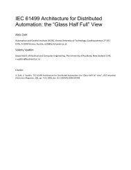
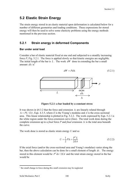
Consider a bar of elastic material fixed at one end and subjected to a steadily increasing<br />
force P, Fig. <strong>5.2</strong>.1. The force is applied slowly so that kinetic energies are negligible.<br />
The initial length of the bar is L . The work dW done in extending the bar a small<br />
amount d Δ is 1<br />
dW = PdΔ<br />
(<strong>5.2</strong>.1)<br />
L dΔ<br />
Δ<br />
Figure <strong>5.2</strong>.1: a bar loaded by a constant stress<br />
It was shown in §4.3.2 that the force and extension Δ are linearly related through<br />
Δ = PL / EA , Eqn. 4.3.5, where E is the Young’s modulus and A is the cross sectional<br />
area. This linear relationship is plotted in Fig. <strong>5.2</strong>.2. The work expressed by Eqn. <strong>5.2</strong>.1 is<br />
the white region under the force-extension curve (line). The total work done during the<br />
complete extension up to a final force P and final extension Δ is the total area beneath<br />
the curve.<br />
The work done is stored as elastic strain energy U and so<br />
2<br />
1 P L<br />
U = PΔ<br />
=<br />
(<strong>5.2</strong>.2)<br />
2 2EA<br />
If the axial force (and/or the cross-sectional area and Young’s modulus) varies along the<br />
bar, then the above calculation can be done for a small element of length dx . The energy<br />
2<br />
stored in this element would be P dx / 2EA<br />
and the total strain energy stored in the bar<br />
would be<br />
1 the small change in force during this small extension may be neglected<br />
Solid Mechanics Part I 180<br />
Kelly<br />
P
dW<br />
U<br />
=<br />
L<br />
∫<br />
0<br />
2<br />
P<br />
dx<br />
2EA<br />
Figure <strong>5.2</strong>.2: force-displacement curve for uniaxial load<br />
The strain energy is always positive, due to the square on the force P, regardless of<br />
whether the bar is being compressed or elongated.<br />
Note the factor of one half in Eqn. <strong>5.2</strong>.2. The energy stored is not simply force times<br />
displacement because the force is changing during the deformation.<br />
Circular Bar in Torsion<br />
P<br />
force-extension<br />
curve<br />
Section <strong>5.2</strong><br />
Solid Mechanics Part I 181<br />
Kelly<br />
(<strong>5.2</strong>.3)<br />
Consider a circular bar subjected to a torque T. The torque is equivalent to a couple: two<br />
forces of magnitude F acting in opposite directions and separated by a distance 2 r as in<br />
Fig. <strong>5.2</strong>.3; T = 2Fr<br />
. As the bar twists through a small angle Δ φ , the forces each move<br />
through a distance s = rΔφ<br />
. The work done is therefore ΔW = 2 ( Fs)<br />
= TΔφ<br />
.<br />
r<br />
dΔ<br />
Figure <strong>5.2</strong>.3: torque acting on a circular bar<br />
It was shown in §4.4 that the torque and angle of twist are linearly related through Eqn.<br />
4.4.10, φ = TL / GJ , where L is the length of the bar, G is the shear modulus and J is the<br />
polar moment of inertia. The angle of twist can be plotted against the torque as in Fig.<br />
<strong>5.2</strong>.4.<br />
The total strain energy stored in the cylinder during the straining up to a final angle of<br />
twist φ is the work done, equal to the shaded area in Fig. <strong>5.2</strong>.4, leading to<br />
Δφ<br />
F<br />
Δ<br />
2<br />
1 T L<br />
U = φ T =<br />
(<strong>5.2</strong>.4)<br />
2 2GJ
ΔW<br />
Figure <strong>5.2</strong>.4: torque – angle of twist plot for torsion<br />
Section <strong>5.2</strong><br />
Again, if the various quantities are varying along the length of the bar, then the total strain<br />
energy can be expressed as<br />
Beam subjected to a Pure Moment<br />
T<br />
U<br />
=<br />
L<br />
∫<br />
0<br />
2<br />
T<br />
dx<br />
2GJ<br />
Solid Mechanics Part I 182<br />
Kelly<br />
(<strong>5.2</strong>.5)<br />
As with the bar under torsion, the work done by a moment M as it moves through an<br />
angle d θ is Md θ . The moment is related to the radius of curvature R through Eqns.<br />
4.6.35-36, M = EI / R , where E is the Young’s modulus and I is the moment of inertia.<br />
The length L of a beam and the angle subtended θ are related to R through L = Rθ<br />
, Fig.<br />
<strong>5.2</strong>.5, and so moment and angle θ are linearly related through θ = ML / EI .<br />
θ / 2<br />
Δφ<br />
Figure <strong>5.2</strong>.5: beam of length L under pure bending<br />
The total strain energy stored in a bending beam is then<br />
and if the moment and other quantities vary along the beam,<br />
θ<br />
R<br />
θ / 2<br />
M M<br />
2<br />
1 M L<br />
U = θ M =<br />
(<strong>5.2</strong>.6)<br />
2 2EI
U<br />
=<br />
L<br />
∫<br />
0<br />
2<br />
M<br />
dx<br />
2EI<br />
Section <strong>5.2</strong><br />
Solid Mechanics Part I 183<br />
Kelly<br />
(<strong>5.2</strong>.7)<br />
This expression is due to the flexural stress σ x . A beam can also store energy due to<br />
shear stress τ ; this latter energy is usually much less than that due to the flexural stresses<br />
provided the beam is slender – this is discussed further below.<br />
Example<br />
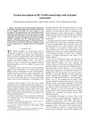
Consider the bar with varying circular cross-section shown in Fig. <strong>5.2</strong>.6. The Young’s<br />
modulus is GPa<br />
200 .<br />
Figure <strong>5.2</strong>.6: a loaded bar<br />
The strain energy stored in the bar when a force of 2 kN is applied at the free end is<br />
3 2<br />
( 2×<br />
10 ) ( 2)<br />
⎛<br />
⎜ 1 1<br />
+<br />
11<br />
2<br />
2(<br />
2×<br />
10 ) ⎜ −2<br />
−2<br />
( 5×<br />
10 ) ( 3×<br />
10 )<br />
L 2<br />
P<br />
U = ∫ dx =<br />
2EA<br />
0<br />
π ⎝<br />
⎞<br />
⎟<br />
−3<br />
= 9.<br />
62×<br />
10 Nm (<strong>5.2</strong>.8)<br />
2 ⎟<br />
⎠<br />
■<br />
<strong>5.2</strong>.2 The Work-<strong>Energy</strong> Principle<br />
The work-energy principle for elastic materials, that is, the fact that the work done by<br />
external forces is stored as elastic energy, can be used directly to solve some simple<br />
problems. To be precise, it can be used to solve problems involving a single force and for<br />
solving for the displacement in the direction of that force. By force and displacement<br />
here it is meant generalised force and generalised displacement, that is a<br />
force/displacement pair, a torque/angle of twist pair or a moment/bending angle pair.<br />
More complex problems need to be solved using more sophisticated energy methods,<br />
such as Castiglianos’ method discussed further below.<br />
Example<br />
2m<br />
r = 5cm<br />
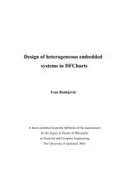
Consider the beam of length L shown in Fig. <strong>5.2</strong>.7, pinned at one end (A) and simply<br />
supported at the other (C). A moment M 0 acts at B, a distance L 1 from the left-hand end.<br />
The cross-section is rectangular with depth b and height h. The work-energy principle<br />
can be used to calculate the angle θ B through which the moment at B rotates.<br />
2m<br />
r<br />
= 3cm<br />
2kN
Figure <strong>5.2</strong>.7: a beam subjected to a moment at B<br />
The moment along the beam can be calculated from force and moment equilibrium,<br />
⎧ − M 0x<br />
/ L,<br />
⎪<br />
M = ⎨<br />
⎪⎩ M 0 ( 1−<br />
x / L)<br />
,<br />
0 < x < L<br />
< x < L<br />
The strain energy stored in the bar (due to the flexural stresses only) is<br />
Section <strong>5.2</strong><br />
Solid Mechanics Part I 184<br />
Kelly<br />
L<br />
1<br />
1<br />
(<strong>5.2</strong>.9)<br />
L 2<br />
2 L1<br />
2 L2<br />
2<br />
2 3<br />
M 6M<br />
0 ⎪⎧<br />
⎛ x ⎞ ⎛ x ⎞ ⎪⎫<br />
2M<br />
0 L2<br />
U = ∫ dx =<br />
dx 1 dx<br />
3 ⎨<br />
⎟ ⎬ = 3 2<br />
2EI<br />
L<br />
L<br />
0 Ebh ∫ ⎜ ⎟ + ∫ ⎜ −<br />
(<strong>5.2</strong>.10)<br />
⎪⎩ 0 ⎝ ⎠ L ⎝ ⎠ ⎪⎭<br />
Ebh L<br />
1<br />
The work done by the applied moment is M θ / 2 and so<br />
<strong>5.2</strong>.3 <strong>Strain</strong> <strong>Energy</strong> Density<br />
0 B<br />
3<br />
4M<br />
0L2<br />
θ B = 3 2<br />
Ebh L<br />
(<strong>5.2</strong>.11)<br />
■<br />
The strain energy will in general vary throughout a body and for this reason it is useful to<br />
introduce the concept of strain energy density, which is a measure of how much energy<br />
is stored in small volume elements throughout a material.<br />
Consider again a bar of subjected to a uniaxial force P. A small volume element with<br />
edges aligned with the x , y,<br />
z axes as shown in Fig. <strong>5.2</strong>.8 will then be subjected to a stress<br />
σ xx only. The volume of the element is dV = dxdydz .<br />
From Eqn. <strong>5.2</strong>.2, the strain energy in the element is<br />
L<br />
A B<br />
C<br />
M 0<br />
L1 L2<br />
( σ dydz)<br />
2<br />
xx dx<br />
U = (<strong>5.2</strong>.12)<br />
2Edydz
P<br />
Figure <strong>5.2</strong>.8: a volume element under stress<br />
The strain energy density u is defined as the strain energy per unit volume:<br />
Section <strong>5.2</strong><br />
2<br />
σ xx<br />
u = (<strong>5.2</strong>.13)<br />
2E<br />
The total strain energy in the bar may now be expressed as this quantity integrated over<br />
the whole volume,<br />
U = udV<br />
(<strong>5.2</strong>.14)<br />
which, for a constant cross-section A and length L reads U = A udx<br />
. From Hooke’s<br />
0<br />
law, the strain energy density of Eqn. <strong>5.2</strong>.13 can also be expressed as<br />
Solid Mechanics Part I 185<br />
Kelly<br />
∫<br />
V<br />
∫<br />
L<br />
1<br />
u = σ xxε<br />
xx<br />
(<strong>5.2</strong>.15)<br />
2<br />
As can be seen from Fig. <strong>5.2</strong>.9, this is the area under the uniaxial stress-strain curve.<br />
u<br />
σ xx<br />
σ<br />
dy<br />
dx<br />
dz<br />
σ xx<br />
volume element<br />
Figure <strong>5.2</strong>.9: stress-strain curve for elastic material<br />
Note that the element does deform in the y and z directions but no work is associated with<br />
those displacements since there is no force acting in those directions.<br />
The strain energy density for an element subjected to a σ yy stress only is, by the same<br />
arguments, σ yyε<br />
yy / 2 , and that due to a σ zz stress is σ zzε<br />
zz / 2 . Consider next a shear<br />
stress σ xy acting on the volume element to produce a shear strain ε xy as illustrated in Fig.<br />
ε<br />
z<br />
y<br />
P<br />
x
Section <strong>5.2</strong><br />
<strong>5.2</strong>.10. The element deforms with small angles θ and λ as illustrated. Only the stresses<br />
on the upper and right-hand surfaces are shown, since the stresses on the other two<br />
surfaces do no work. The force acting on the upper surface is σ xydxdz<br />
and moves<br />
through a displacement λ dy . The force acting on the right-hand surface is σ xydydz<br />
and<br />
moves through a displacement θ dx . The work done when the element moves through<br />
angles d θ and d λ is then, using the definition of shear strain, Eqn. 3.6.1,<br />
( σ dxdz)(<br />
dλdy)<br />
+ ( σ dydz)(<br />
dθdx)<br />
= ( dxdydz)<br />
σ ( 2d<br />
)<br />
dW = ε (<strong>5.2</strong>.16)<br />
xy<br />
xy<br />
and, with shear stress proportional to shear strain as in Fig. <strong>5.2</strong>.9, the strain energy density<br />
is<br />
u = 2 ∫σ<br />
xydε<br />
xy = σ xyε<br />
xy<br />
(<strong>5.2</strong>.17)<br />
Figure <strong>5.2</strong>.10: a volume element under shear stress<br />
The strain energy can be similarly calculated for the other shear stresses and, in summary,<br />
the strain energy density for a volume element subjected to arbitrary stresses is<br />
( σ ε + σ ε + σ ε ) + ( σ ε + σ ε + σ )<br />
1<br />
u = xx xx yy yy zz zz xy xy yz yz zxε<br />
2<br />
Using Hooke’s law, Eqns. 4.2.9, with Eqn. 4.2.5, the strain energy density can also be<br />
written in the alternative and useful forms {▲Problem 4}<br />
1<br />
u =<br />
2E<br />
μ<br />
=<br />
1−<br />
νμ<br />
=<br />
1−<br />
2ν<br />
Solid Mechanics Part I 186<br />
Kelly<br />
xy<br />
xy<br />
zx<br />
(<strong>5.2</strong>.18)<br />
2 2 2 ν<br />
1 2 2 2<br />
( σ xx + σ yy + σ zz ) − ( σ xxσ<br />
yy + σ yyσ<br />
zz + σ zzσ<br />
xx ) + ( σ xy + σ yz + σ zx )<br />
E<br />
2μ<br />
2 2 2<br />
2 2 2<br />
[ ( 1−ν<br />
) ( ε xx + ε yy + ε zz ) + 2ν<br />
( ε xxε<br />
yy + ε yyε<br />
zz + ε zzε<br />
xx ) ] + 2μ(<br />
ε xy + ε yz + ε zx )<br />
2ν<br />
2 2 2 2<br />
2 2 2<br />
( ε + ε + ε ) + μ(<br />
ε + ε + ε ) + 2μ(<br />
ε + ε + ε )<br />
xx<br />
yy<br />
λdy<br />
<strong>Strain</strong> <strong>Energy</strong> in a Beam due to Shear Stress<br />
zz<br />
dy<br />
y<br />
λ<br />
xx<br />
σ xy<br />
θ<br />
dx<br />
yy<br />
θdx<br />
zz<br />
σ xy<br />
xy<br />
x<br />
yz<br />
zx<br />
(<strong>5.2</strong>.19)
Section <strong>5.2</strong><br />
The shear stresses arising in a beam at location y from the neutral axis are given by Eqn.<br />
4.6.27, τ ( y ) = Q(<br />
y)<br />
V / Ib(<br />
y)<br />
, where Q is the first moment of area of the section of beam<br />
from y to the outer surface, V is the shear force, I is the moment of inertia of the complete<br />
cross-section and b is the thickness of the beam at y. From Eqns. <strong>5.2</strong>.19a and <strong>5.2</strong>.14 then,<br />
the total strain energy in a beam of length L due to shear stress is<br />
2<br />
L 2 2<br />
τ 1 V ⎡ Q ⎤<br />
U = ∫ dV = ∫ ⎢ dA⎥dx<br />
2<br />
V<br />
I ∫ 2<br />
2μ 2 0 μ ⎣ A b ⎦<br />
Solid Mechanics Part I 187<br />
Kelly<br />
(<strong>5.2</strong>.20)<br />
Here V , μ and I are taken to be constant for any given cross-section but may vary along<br />
the beam; Q varies and b may vary over any given cross-section. Expression <strong>5.2</strong>.20 can<br />
be simplified by introducing the form factor for shear f s , defined as<br />
so that<br />
2<br />
A Q<br />
f s ( x)<br />
= dA<br />
2<br />
I ∫<br />
(<strong>5.2</strong>.21)<br />
2<br />
b<br />
U<br />
The form factor depends only on the shape of the cross-section. For example, for a<br />
rectangular cross-section, using Eqn. 4.6.28,<br />
=<br />
1<br />
2<br />
L<br />
∫<br />
0<br />
A<br />
f V<br />
s<br />
2<br />
μA<br />
dx<br />
2<br />
3 2<br />
( / 12)<br />
∫ 2 ⎢<br />
2 ⎜ − y ⎥ =<br />
4 ⎟ dy dz<br />
bh<br />
5<br />
−h<br />
/ 2 b ⎣ ⎝ ⎠⎦<br />
−b<br />
/ 2<br />
(<strong>5.2</strong>.22)<br />
+ h / 2<br />
2<br />
+ b / 2<br />
bh 1 ⎡b<br />
⎛ h ⎞⎤<br />
6<br />
f s ( x)<br />
= ∫<br />
(<strong>5.2</strong>.23)<br />
In a similar manner, the form factor for a circular cross-section is found to be 10 / 9 and<br />
that of a very thin tube is 2.<br />
<strong>5.2</strong>.4 Castigliano’s Second Theorem<br />
The work-energy method is the simplest of energy methods. A more powerful method is<br />
that based on Castigliano’s second theorem 2 , which can be used to solve problems<br />
involving linear elastic materials. As an introduction to Castigliano’s second theorem,<br />
2<br />
consider the case of uniaxial tension, where U = P L / 2EA.<br />
The displacement through<br />
which the force moves can be obtained by a differentiation of this expression with respect<br />
to that force,<br />
dU<br />
dP<br />
PL<br />
=<br />
EA<br />
= Δ<br />
2 Casigliano’s first theorem will be discussed in a later section<br />
2<br />
(<strong>5.2</strong>.24)
Section <strong>5.2</strong><br />
2<br />
Similarly, for torsion of a circular bar, U = T L / 2GJ<br />
, and a differentiation gives<br />
dU / dT = TL / GJ = φ . Further, for bending of a beam it is also seen that dU / dM = θ .<br />
These are examples of Castigliano’s theorem, which states that, provided the body is in<br />
equilibrium, the derivative of the strain energy with respect to the force gives the<br />
displacement corresponding to that force, in the direction of that force. When there is<br />
more than one force applied, then one takes the partial derivative. For example, if n<br />
independent forces P 1, P2<br />
, K , Pn<br />
act on a body, the displacement corresponding to the ith<br />
force is<br />
Before proving this theorem, here follow some examples.<br />
Example<br />
∂U<br />
Δ i =<br />
(<strong>5.2</strong>.25)<br />
∂P<br />
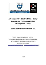
The beam shown in Fig. <strong>5.2</strong>.11 is pinned at A, simply supported half-way along the beam<br />
at B and loaded at the end C by a force P and a moment M 0 .<br />
Figure <strong>5.2</strong>.11: a beam subjected to a force and moment at C<br />
The moment along the beam can be calculated from force and moment equilibrium,<br />
⎧−<br />
Px − 2M<br />
0 x / L,<br />
⎪<br />
M = ⎨<br />
⎪⎩ − M 0 − P(<br />
L − x),<br />
Solid Mechanics Part I 188<br />
Kelly<br />
i<br />
0 < x < L / 2<br />
L / 2 < x < L<br />
The strain energy stored in the bar (due to the flexural stresses only) is<br />
2 L / 2<br />
L<br />
1 ⎪⎧<br />
⎛ 2M<br />
0 ⎞ 2<br />
U = ⎨⎜<br />
P + ⎟ x dx<br />
2EI<br />
L ∫ + ∫<br />
⎪⎩ ⎝ ⎠ 0<br />
L / 2<br />
2 3<br />
2 2<br />
P L 5PM<br />
0L<br />
M 0 L<br />
= + +<br />
24EI<br />
24EI<br />
3EI<br />
L<br />
A C<br />
B<br />
L / 2<br />
L / 2<br />
( M + P(<br />
L − x)<br />
)<br />
0<br />
2<br />
⎪⎫<br />
dx⎬<br />
⎪⎭<br />
(<strong>5.2</strong>.26)<br />
(<strong>5.2</strong>.27)<br />
In order to apply Castigliano’s theorem, the strain energy is considered to be a function of<br />
the two external loads, U = U ( P,<br />
M 0 ) . The displacement associated with the force P is<br />
then<br />
P<br />
M 0
The rotation associated with the moment is<br />
Example<br />
Section <strong>5.2</strong><br />
3<br />
2<br />
∂U<br />
PL 5M<br />
0L<br />
Δ C = = +<br />
(<strong>5.2</strong>.28)<br />
∂P<br />
12EI<br />
24EI<br />
∂U<br />
θ C =<br />
∂M<br />
0<br />
2<br />
5PL 2M<br />
0L<br />
= +<br />
24EI<br />
3EI<br />
(<strong>5.2</strong>.29)<br />
■<br />
Consider next the beam of length L shown in Fig. <strong>5.2</strong>.12, built in at both ends and loaded<br />
centrally by a force P. This is a statically indeterminate problem. In this case, the strain<br />
energy can be written as a function of the applied load and one of the unknown reactions.<br />
M<br />
A<br />
A C<br />
B<br />
Figure <strong>5.2</strong>.12: a statically indeterminate beam<br />
First, the moment in the beam is found from equilibrium considerations to be<br />
P<br />
M = M A + x,<br />
0 < x < L / 2<br />
(<strong>5.2</strong>.30)<br />
2<br />
where M A is the unknown reaction at the left-hand end. Then the strain energy in the<br />
left-hand half of the beam is<br />
L / 2<br />
2 3<br />
2 2<br />
1 ⎛ P ⎞ P L PM AL<br />
M AL<br />
U = M A x dx<br />
2EI<br />
∫ ⎜ + ⎟ = + +<br />
(<strong>5.2</strong>.31)<br />
⎝ 2 ⎠ 192EI<br />
16EI<br />
4EI<br />
The strain energy in the complete beam is double this:<br />
Writing the strain energy as U U ( P,<br />
M )<br />
0<br />
P<br />
L / 2<br />
L / 2<br />
2<br />
2 3<br />
2 2<br />
P L PM AL<br />
M AL<br />
U = + +<br />
(<strong>5.2</strong>.32)<br />
96EI<br />
8EI<br />
2EI<br />
= , the rotation at A is<br />
A<br />
2<br />
∂U<br />
PL M AL<br />
θ A = = +<br />
(<strong>5.2</strong>.33)<br />
∂M<br />
8EI<br />
EI<br />
Solid Mechanics Part I 189<br />
Kelly<br />
A<br />
M C
But θ A = 0 and so Eqn. <strong>5.2</strong>.33 can be solved to get M A = −PL<br />
/ 8 . Then the<br />
displacement at the centre of the beam is<br />
Section <strong>5.2</strong><br />
3<br />
2<br />
3<br />
∂U<br />
PL M AL<br />
PL<br />
Δ B = = + =<br />
(<strong>5.2</strong>.34)<br />
∂P<br />
48EI<br />
8EI<br />
192EI<br />
This is positive in the direction in which the associated force is acting, and so is<br />
downward.<br />
Proof of Castigliano’s Theorem<br />
A proof of Castiligliano’s theorem will be given here for a structure subjected to a single<br />
load. The load P produces a displacement Δ and the strain energy is U = PΔ<br />
/ 2 , Fig.<br />
<strong>5.2</strong>.13. If an additional force dP is applied giving an additional deformation d Δ , the<br />
additional strain energy is<br />
1<br />
dU = PdΔ<br />
+ dPdΔ<br />
2<br />
Solid Mechanics Part I 190<br />
Kelly<br />
■<br />
(<strong>5.2</strong>.35)<br />
If the load P + dP is applied in one step, the work done is ( P + dP)(<br />
Δ + dΔ)<br />
/ 2 . Equating<br />
this to the strain energy U + dU given by Eqn. <strong>5.2</strong>.35 then gives PdΔ = ΔdP<br />
.<br />
Substituting into Eqn. <strong>5.2</strong>.35 leads to<br />
1<br />
dU = ΔdP<br />
+ dPdΔ<br />
2<br />
(<strong>5.2</strong>.36)<br />
Dividing through by dP and taking the limit as dP → 0 results in Castigliano’s second<br />
theorem, dU / dP = Δ .<br />
P + dP<br />
P<br />
Figure <strong>5.2</strong>.13: force-displacement curve<br />
In fact, dividing Eqn. <strong>5.2</strong>.35 through by d Δ and taking the limit as d Δ → 0 results in<br />
Castigliano’s first theorem, dU / dΔ<br />
= P . It will be shown later that this first theorem,<br />
unlike the second, in fact holds also for the case when the elastic material is non-linear.<br />
<strong>5.2</strong>.5 Dynamic <strong>Elastic</strong>iy<br />
Δ<br />
Δ + dΔ
Impact and Dynamic Loading<br />
Section <strong>5.2</strong><br />
Consider the case of a weight P dropped instantaneously onto the end of an elastic bar. If<br />
the weight P had been applied gradually from zero, the strain energy stored at the final<br />
1 force P and final displacement Δ 0 would be 2 P Δ 0 . However, the instantaneously<br />
applied load is constant throughout the deformation and work done up to a displacement<br />
Δ 0 is P Δ 0 , Fig. <strong>5.2</strong>.14. The difference between the two implies that the bar acquires a<br />
kinetic energy (see Eqn. 5.1.19); the material particles accelerate from their equilibrium<br />
positions during the compression.<br />
As deformation proceeds beyond Δ 0 , it is clear from Fig. <strong>5.2</strong>.14 that the strain energy is<br />
increasing faster than the work being done by the weight and so there must be a drop in<br />
kinetic energy; the particles begin to decelerate. Eventually, at Δ max = 2Δ 0 , the work<br />
done by the weight exactly equals the strain energy stored and the material is at rest.<br />
However, the material is not in equilibrium – the equilibrium position for a load P is Δ 0 –<br />
and so the material begins to accelerate back to where Δ 0 .<br />
Figure <strong>5.2</strong>.14: non-equilibrium loading<br />
The bar and weight will continue to oscillate between 0 and Δ max indefinitely. In a real<br />
material, internal friction will cause the vibration to decay.<br />
Thus the maximum compression of a bar under impact loading is twice that of a bar<br />
subjected to the same load gradually.<br />
Example<br />
P<br />
Δ Δ<br />
0<br />
max<br />
Consider a weight w dropped from a height h. If one is interested in the final, maximum,<br />
displacement of the bar, Δ max , one does not need to know about the detailed and complex<br />
transfer of energies during the impact; the energy lost by the weight equals the strain<br />
energy stored in the bar:<br />
1<br />
w ( h + Δ max ) = PΔ<br />
max<br />
(<strong>5.2</strong>.37)<br />
2<br />
where P is the force acting on the bar at its maximum compression. For an elastic bar,<br />
P Δ EA/<br />
L<br />
P = kΔ<br />
,<br />
= max , or, introducing the stiffness k so that max<br />
Solid Mechanics Part I 191<br />
Kelly
1 2 EA<br />
w ( h + Δ ) = kΔ<br />
max , k =<br />
2<br />
L<br />
which is a quadratic equation in Δ max and can be solved to get<br />
Δ<br />
Section <strong>5.2</strong><br />
max (<strong>5.2</strong>.38)<br />
w ⎧ 2hk<br />
⎫<br />
= ⎨1<br />
+ 1+<br />
⎬<br />
k ⎩ w ⎭<br />
max (<strong>5.2</strong>.39)<br />
If the force w had been applied gradually, then the displacement would have been<br />
Δ w / k , the “st” standing for “static”, and Eqn. 5.1.39 can be re-written as<br />
st =<br />
If = 0<br />
Δ<br />
max<br />
= Δ<br />
st<br />
⎧<br />
⎨1<br />
+<br />
⎩<br />
2h<br />
⎫<br />
1+<br />
⎬<br />
(<strong>5.2</strong>.40)<br />
Δ st ⎭<br />
Δ = 2Δ .<br />
h , so that the weight is just touching the bar when released, then max st<br />
<strong>5.2</strong>.6 Problems<br />
1. Show that the strain energy in a bar of length L and cross sectional area A hanging<br />
from a ceiling and subjected to its own weight is given by (at any section, the force<br />
acting is the weight of the material below that section)<br />
2 2 3<br />
Aρ<br />
g L<br />
U =<br />
6E<br />
2. Consider the circular bar shown below subject to torques at the free end and where the<br />
cross-sectional area changes. The shear modulus is G = 80GPa<br />
. Calculate the strain<br />
energy in the bar(s).<br />
1m<br />
1m<br />
r = 5cm<br />
6kNm<br />
r = 3cm<br />
4kNm<br />
3. Two bars of equal length L and cross-sectional area A are pin-supported and loaded by<br />
a force F as shown below. Derive an expression for the vertical displacement at point<br />
A using the direct work-energy method, in terms of L, F, A and the Young’s modulus<br />
E.<br />
Solid Mechanics Part I 192<br />
Kelly<br />
■
4. Derive the strain energy density equations <strong>5.2</strong>.19.<br />
Section <strong>5.2</strong><br />
5. For the beam shown in Fig. <strong>5.2</strong>.7, use the expression <strong>5.2</strong>.22 to calculate the strain<br />
energy due to the shear stresses. Take the shear modulus to be G = 80GPa<br />
. Compare<br />
this with the strain energy due to flexural stress given by Eqn. <strong>5.2</strong>.10.<br />
6. Consider a simply supported beam of length L subjected to a uniform load w N/m.<br />
Calculate the strain energy due to both flexural stress and shear stress for (a) a<br />
rectangular cross-section of depth times height b × h , (b) a circular cross-section with<br />
radius r. What is the ratio of the shear-to-flexural strain energies in each case?<br />
7. Consider the tapered bar of length L and square cross-section shown below, built-in at<br />
one end and subjected to a uniaxial force F at its free end. The thickness is h at the<br />
built-in end. Evaluate the displacement in terms of the (constant) Young’s modulus E<br />
at the free end using (i) the work-energy theorem, (ii) Castigliano’s theorem<br />
h<br />
o<br />
45<br />
A<br />
F<br />
o<br />
45<br />
8. Consider a cantilevered beam of length L and constant cross-section subjected to a<br />
uniform load w N/m. The beam is built-in at x = 0 and has a Young’s modulus E.<br />
Use Castigliano’s theorem to calculate the deflection at x = L . Consider only the<br />
flexural strain energy. [Hint: place a fictitious “dummy” load F at x = L and set to<br />
zero once Castigliano’s theorem has been applied]<br />
9. Consider the statically indeterminate uniaxial problem shown below, two bars joined<br />
at x = L , built in at x = 0 and x = 2L<br />
, and subjected to a force F at the join. The<br />
cross-sectional area of the bar on the left is 2A and that on the right is A. Use (i) the<br />
work-energy theorem and (ii) Castigliano’s theorem to evaluate the displacement at<br />
x = L .<br />
Solid Mechanics Part I 193<br />
Kelly<br />
F<br />
L L<br />
F<br />
L L