Harmonics mitigation and solutions - Schneider Electric
Harmonics mitigation and solutions - Schneider Electric
Harmonics mitigation and solutions - Schneider Electric

You also want an ePaper? Increase the reach of your titles
YUMPU automatically turns print PDFs into web optimized ePapers that Google loves.
<strong>Harmonics</strong> <strong>mitigation</strong> <strong>and</strong> <strong>solutions</strong>
Summary<br />
I. Introduction<br />
II. <strong>Harmonics</strong> <strong>mitigation</strong><br />
solution<br />
III. Case study<br />
lV.Conclusion<br />
<strong>Schneider</strong> <strong>Electric</strong> 2
I. Introduction<br />
II. Harmonic <strong>mitigation</strong> solution<br />
III. Case study<br />
lV.Conclusion<br />
<strong>Schneider</strong> <strong>Electric</strong> 3
I. Introduction<br />
●The quality of electrical power is determined by the voltage<br />
● High-quality voltage is the best guarantee for continuous operation of<br />
equipment<br />
The voltage signal must be perfect<br />
at the source...<br />
Line impedance<br />
Type of installation<br />
Length of cables<br />
Internal impedance of<br />
equipment...<br />
... because distortion may occur at the<br />
end of the line<br />
The harmonic current<br />
from the load<br />
Type of load<br />
Power supply<br />
technology<br />
<strong>Schneider</strong> <strong>Electric</strong> 4
I. Introduction<br />
II. Harmonic <strong>mitigation</strong> solution<br />
III. Case study<br />
lV.Conclusion<br />
<strong>Schneider</strong> <strong>Electric</strong> 5
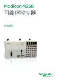
II. What is a harmonic waveform?<br />
●Harmonic waveform is a distortion of the normal<br />
Sinewave<br />
●It is characterized by its distortion level<br />
● For voltage (THD U - Total Harmonic Voltage<br />
Distortion)<br />
● For current (THD I - Total Harmonic Current<br />
Distortion)<br />
1.5<br />
1<br />
0.5<br />
0<br />
-0.5<br />
-1<br />
-1.5<br />
=<br />
1.5<br />
1<br />
0.5<br />
0<br />
-0.5<br />
-1<br />
-1.5<br />
Signal with harmonics Fundamental H1 <strong>Harmonics</strong> H2 to Hn<br />
THD (U or I) % = 100 x<br />
H1 = 50Hz Hn = n x 50Hz<br />
<strong>Schneider</strong> <strong>Electric</strong> 6<br />
+<br />
1.5<br />
1<br />
0.5<br />
0<br />
-0.5<br />
-1<br />
-1.5
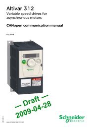
II. Current distortion<br />
●Waveform examples <strong>and</strong> harmonic<br />
spectrum<br />
● Three- phase loads<br />
Variable speed drive<br />
Lifts…<br />
● Single-phase loads<br />
● Computers<br />
● Phones<br />
● Lighting ...<br />
H11 H13 H17 H19 H21 H23<br />
<strong>Schneider</strong> <strong>Electric</strong> 7<br />
100<br />
50<br />
0<br />
100<br />
50<br />
0<br />
H1 H5 H7<br />
Danger<br />
H1 H3 H5<br />
Danger<br />
H7 H9 H11 H13 H15<br />
H17
II. The effects of harmonics<br />
●Voltage distortion:<br />
● Excessive temperature rise in motors<br />
● <strong>Electric</strong>al noises<br />
● Sensitive electronic equipment malfunction<br />
●Increase in the apparent power <strong>and</strong> over-sizing of sources (UPS,<br />
Genset, etc.), capacitors, cables...<br />
● Derating of electrical equipment or over-sizing<br />
● Accelerated ageing of equipment<br />
●Flow of current in the neutral conductor <strong>and</strong> consequently in the<br />
PEN:<br />
● Excessive temperature rise in transformer<br />
● Tripping of circuit breakers<br />
<strong>Schneider</strong> <strong>Electric</strong> 8
II. The effects of harmonics<br />
●Voltage distortion: influence of THDI on the THDU<br />
Main LV<br />
Switchboard (MLVS)<br />
feeder MS1 feeder MS2 feeder MSn<br />
Secondary<br />
switchboard<br />
feeder S1 feeder S2 feeder S3<br />
Final distribution<br />
enclosure<br />
LV<br />
M M M<br />
Increased RMS current<br />
Non-linear current<br />
circulating in the cables<br />
Increased THDU<br />
<strong>Schneider</strong> <strong>Electric</strong> 9
II. The effects of harmonics<br />
●Increase in the apparent power <strong>and</strong> over-sizing of<br />
sources<br />
> Linear load without harmonics:<br />
• Cos phi = Power factor = P/S<br />
φ<br />
ST (VA)<br />
P (W)<br />
> Non-linear load :<br />
S (VA)<br />
• DPF = Displacement Power Factor - P 1 /S 1 ( 50 Hz<br />
fundamental current only)<br />
• True Power factor = P/ST<br />
Q (var)<br />
D harmonic<br />
P 2 + Q 2<br />
> S = apparent power<br />
<strong>Schneider</strong> <strong>Electric</strong> 10<br />
S =<br />
S =<br />
P 2 + Q 2 + D 2
II. The effects of harmonics<br />
2<br />
0<br />
0 90 180 270 360 450<br />
-2<br />
-4<br />
-6<br />
●Flow of current in the neutral conductor<br />
● The H3 harmonic currents <strong>and</strong> multiples flow in the neutral<br />
conductor.<br />
● The cross-sectional area of the neutral conductor must be increased<br />
(1.7 times that of the phases for switch-mode power supplies).<br />
Phase 1<br />
Phase 2<br />
Phase 3<br />
3rd Harmonic, phase 1<br />
3rd Harmonic, phase 2<br />
3rd Harmonic, phase 3<br />
Total 3rd Harmonic<br />
I3,I9,I15<br />
<strong>Schneider</strong> <strong>Electric</strong> 11
1<br />
Over-sizing of sources,<br />
cables, etc.<br />
1<br />
II. <strong>Harmonics</strong> <strong>mitigation</strong> <strong>solutions</strong><br />
●Electromechanical <strong>solutions</strong><br />
●Active filters<br />
- The harmonics are not<br />
eliminated.<br />
- Very costly<br />
Transformers with<br />
different couplings<br />
2 Limits h3 <strong>and</strong> multiples.<br />
h3 h9<br />
D<br />
yn<br />
2<br />
D<br />
h5 h7<br />
Normal or replacement<br />
sources<br />
Tuned<br />
filters<br />
Anti-harm.<br />
reactors<br />
&<br />
series filters<br />
<strong>Schneider</strong> <strong>Electric</strong> 12<br />
D<br />
d y y<br />
3 4<br />
Y<br />
y<br />
p1 = p2 p1 = p2<br />
3 <strong>and</strong> 4 attenuate h5 <strong>and</strong><br />
h7 (6-pulse bridge)<br />
5<br />
6<br />
L<br />
F<br />
5 6<br />
Attenuates harmonics<br />
at the tuning frequency.<br />
Decreases THD(i).
II. Passive filter: architecture & design<br />
●3-phase + neutral filter<br />
●Composed of only two elements<br />
● 1 serial three-phase inductance<br />
● 1 parallel three-phase inductance<br />
Ph<br />
Mains<br />
N<br />
Lo<br />
Filter<br />
Zo<br />
Load<br />
No capacitors<br />
No power electronics<br />
No batteries<br />
No micro controllers<br />
Unmatched reliability, same as that of a dry transformer<br />
<strong>Schneider</strong> <strong>Electric</strong> 13
II. Cleanwave: solution for neutral currents<br />
●At A Glance:<br />
● Zero sequence harmonic filter<br />
● Reduces neutral currents in<br />
commercial & industrial buildings<br />
● Balancing of 3-phase currents<br />
● 12-280 kVA (exp<strong>and</strong>able)<br />
● 3-phase low voltage applications<br />
●Customer benefits<br />
● Simple <strong>and</strong> highly reliable design<br />
● Reduction of neutral currents by 10:1<br />
● Compliance with harmonic st<strong>and</strong>ards<br />
● Capacity upgrade by parallel<br />
connection<br />
● Operational savings<br />
● Easy integration into power<br />
distribution cabinets (Chassis Format)<br />
● Easy sizing <strong>and</strong> installer friendly<br />
input<br />
output<br />
<strong>Schneider</strong> <strong>Electric</strong> 14
II. Sizing cleanwave<br />
●CleanWave is designed for the most dem<strong>and</strong>ing situations<br />
● H3 harmonics <strong>and</strong> multiple: THDI up to 80%<br />
● Neutral current = 1.8 times phase current<br />
●Very easy sizing<br />
Max power or max. I phase<br />
of the load<br />
Selection of the filter of<br />
immediately higher<br />
power or current<br />
25 kVA load<br />
Selection of the<br />
30 kVA CleanWave<br />
<strong>Schneider</strong> <strong>Electric</strong> 15
I1: 150A<br />
I2: 149A<br />
I3: 151A<br />
In: 21A<br />
I1 in<br />
In in<br />
I1 out<br />
In out<br />
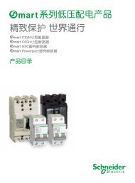
II. Unbalanced load tests<br />
Balanced Without Ph3 Without Ph2 & 3<br />
Input:<br />
In = 21 A<br />
Output:<br />
In = 242 A<br />
I1: 126A<br />
I2: 126A<br />
I3: 127A<br />
In: 242A<br />
I1: 112A<br />
I2: 122A<br />
I3: 65A<br />
In: 25A<br />
I1 in<br />
In in<br />
I1 out<br />
In out<br />
Input:<br />
In = 25 A<br />
Output:<br />
In = 201 A<br />
I1: 126A I1: 107A<br />
I2: 126A I2: 46A<br />
<strong>Schneider</strong> <strong>Electric</strong> 16<br />
I3: 0A<br />
I3: 46A<br />
In: 201A In: 25A<br />
I1 in<br />
In in<br />
I1 out<br />
In out<br />
Input:<br />
In = 25 A<br />
Output:<br />
In = 150 A<br />
I1: 154A<br />
I2: 0A<br />
I3: 0A<br />
In: 150A<br />
1mv=1 A 1mv=1 A<br />
1mv=1 A
II. Active harmonic conditioner: architecture &<br />
design<br />
Power<br />
source<br />
I source I load<br />
Active<br />
harmonic<br />
conditioner<br />
I conditioner<br />
Non-linear<br />
load<br />
● The active harmonic conditioner generates the harmonic currents<br />
required by non-linear loads. These currents are opposite in phase with<br />
respect to the current supplied by the source.<br />
● The A.H.C is sized only for harmonic currents<br />
● The current consumed by the load is therefore:<br />
I load = I source + I conditioner<br />
<strong>Schneider</strong> <strong>Electric</strong> 17
II. Reducing upstream harmonic pollution<br />
2<br />
1,5<br />
1<br />
0,5<br />
0<br />
-0,5<br />
-1<br />
-1,5<br />
-2<br />
4<br />
I. sinusoidal<br />
The<br />
harmonics are<br />
eliminated<br />
upstream <strong>and</strong><br />
apparent<br />
power is<br />
reduced<br />
+<br />
Active<br />
conditioner<br />
supplies the<br />
required<br />
harmonics to<br />
the load<br />
2<br />
1,5<br />
1<br />
0,5<br />
0<br />
-0,5<br />
-1<br />
-2<br />
I. conditioner<br />
3<br />
<strong>Schneider</strong> <strong>Electric</strong> 18<br />
2<br />
=<br />
1,5<br />
0,5<br />
-0,5<br />
-1,5<br />
CTs analyze the<br />
harmonics<br />
required by the<br />
load<br />
2<br />
1<br />
0<br />
-1<br />
-2<br />
I. load<br />
1<br />
Equipment is the<br />
source of<br />
harmonics
II. Sinewave st<strong>and</strong>ard solution: 20-480A of<br />
harmonic compensation<br />
● SineWave includes everything for a simple <strong>and</strong> functional basic solution:<br />
- EMC filter to comply with EN55011 level A <strong>and</strong> IEC 1000-4<br />
- 7-language user interface<br />
- Diagnostic <strong>and</strong> maintenance menu<br />
- Basic indications by 3 LEDs<br />
- Relay contacts for remote indications<br />
- Terminal blocks for power <strong>and</strong> sensor connections<br />
- Wide choice of current transformers: split or closed<br />
<strong>Schneider</strong> <strong>Electric</strong> 19
II. Sinewave features<br />
● Input<br />
• Voltage : 400 V , - 20% , + 15%<br />
• Phases : 3-phase with or without neutral. Compatible<br />
Operation with single phase <strong>and</strong> unbalanced load<br />
• Frequency : 50 Hz or 60 Hz, +/- 8% auto-sensing<br />
● Compensation characteristics<br />
• <strong>Harmonics</strong> covered : H 2 to H 25<br />
• Type of compensation : <strong>Harmonics</strong> - cos phi - mixed (Hn + cos)<br />
• Compensation mode : Overall or selective (specific harmonics)<br />
• Attenuation ratio : >10 at full load ( THDI)<br />
• Cos phi correction : Up to 1<br />
• THDU reduction : According to the installation parameters, THDU<br />
reduction will be determinated by the SITE AUDIT<br />
• Response time : < 40 ms in overall current compensation mode<br />
• Overload : Automatic current limitation<br />
<strong>Schneider</strong> <strong>Electric</strong> 20
II. Example: Variable Speed Drive load<br />
2<br />
1,5<br />
1<br />
0.5<br />
0<br />
-0.5<br />
-1<br />
-1,5<br />
-2<br />
Mains current without<br />
active conditioner<br />
I phase = 48 A<br />
THDI = 81%<br />
I neutral = 42 A<br />
S = 10.6 kVA<br />
Power factor = 0.77<br />
Cos phi 1 = 0.99<br />
<strong>Schneider</strong> <strong>Electric</strong> 21<br />
2<br />
1,5<br />
1<br />
0.5<br />
0<br />
-0.5<br />
-1<br />
-1,5<br />
-2<br />
Mains current with<br />
active conditioner<br />
I phase = 38A (-21%)<br />
THDI (reduced by a factor of 24) = 3.4%<br />
I neutral = 2.6 A<br />
S = 8.4 kVA<br />
Power factor = 1<br />
Cos phi 1 = 1
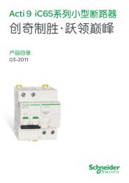
II. Example: Variable Speed Drive load<br />
120<br />
100<br />
80<br />
60<br />
40<br />
20<br />
0<br />
H1<br />
Test Results of a 60 A Active Conditioner<br />
H3<br />
H5<br />
H7<br />
H9<br />
H11<br />
H13<br />
H15<br />
H17<br />
H19<br />
Harmonic current without SineWave Harmonic current with SineWave<br />
THDI = 92.6%<br />
PF = 0.73<br />
H21<br />
2.9%<br />
1.0<br />
Reduction of 27% in the line RMS current<br />
<strong>Schneider</strong> <strong>Electric</strong> 22<br />
120<br />
100<br />
80<br />
60<br />
40<br />
20<br />
0<br />
H1<br />
H3<br />
H5<br />
H7<br />
H9<br />
H11<br />
H13<br />
H15<br />
H17<br />
H19<br />
H21
II. Accusine solution<br />
● Robust design suitable for heavy industrial<br />
applications<br />
● IP54 protection enclosure is st<strong>and</strong>ard<br />
● Full EMC compliance with 89/336EEC,<br />
conforms to IEC/EN 60439-1, EN61000-6-4<br />
class A, EN61000-6-2 st<strong>and</strong>ards<br />
● Current output ratings of 50 A, 100 A or 300<br />
A<br />
● Can be paralleled up to 10 units in any rating<br />
combination<br />
● Ultra fast response time (1/2 cycle)<br />
● Cancel harmonic up to 50th order<br />
● ABS Certified for Marine applications<br />
<strong>Schneider</strong> <strong>Electric</strong> 23
II. Accusine features<br />
● Input<br />
• Voltage : 208-480V, - 10% , + 10%; auto sensing<br />
• Phases : 3-phase, 3-wire with or without neutral.<br />
Compatible Operation with single phase<br />
<strong>and</strong> unbalanced load<br />
• Frequency : 50 Hz or 60 Hz, +/- 5% auto-sensing<br />
● Compensation characteristics<br />
• <strong>Harmonics</strong> covered : H 2 to H 50 (no filtering on neutral conductor)<br />
• Type of compensation<br />
cos)<br />
: <strong>Harmonics</strong> - cos phi - mixed (Hn +<br />
• Compensation mode : overall<br />
• Attenuation ratio : 10:1 overall<br />
• Cos phi correction<br />
VARS<br />
: Up to unity; can also inject lagging<br />
• THDU reduction<br />
IEEE519; UK G5/4 or<br />
: Guaranteed compliance with<br />
IEC 61000-2-3<br />
• Response time : < 10 ms<br />
• Overload : Automatic current limitation<br />
<strong>Schneider</strong> <strong>Electric</strong> 24
II. Customer benefits / active power <strong>solutions</strong><br />
●Safe <strong>and</strong> reliable AC electrical distribution systems<br />
● Overloading <strong>and</strong> overheating of the neutral conductor cancelled<br />
● Nuisance tripping of protection circuit breakers avoided<br />
●Improved power quality<br />
● Reduction of the THD(V)<br />
● Cancellation of the voltage potential on the neutral conductor<br />
●Increased lifetime of AC distribution system equipment<br />
●Over-sizing cables, transformers <strong>and</strong> other AC distribution equipment<br />
avoided<br />
●Compliance of installations with harmonic st<strong>and</strong>ards ensured<br />
●Improved power factor<br />
●Lower energy expenses/bills<br />
<strong>Schneider</strong> <strong>Electric</strong> 25
I. Introduction<br />
II. Harmonic <strong>mitigation</strong> solution<br />
III. Case study<br />
lV.Conclusion<br />
<strong>Schneider</strong> <strong>Electric</strong> 26
III. Accusine application case study<br />
●Oil platform in the North Sea with<br />
turbine / diesel generators feeding 6 KV<br />
network<br />
● Mechanical resonance on the platform<br />
when pump VFDs operated above 49 Hz<br />
due to generator loading<br />
● Each 1 Hz increment in pump speed<br />
equals $6k/day incremental revenue per<br />
pump (2003 prices)<br />
●2 x 600 KW VFDs at 380V<br />
● 300A AHF for each VFD<br />
● Operating in harmonic + power factor<br />
correction mode<br />
● Increased pump speed by 1 Hz<br />
<strong>Schneider</strong> <strong>Electric</strong> 27
III. Accusine application case study<br />
Voltage waveform - AHF OFF<br />
Voltage waveform - AHF ON<br />
●THD(I) reduced from<br />
31.8% to 7.2%<br />
●PF from 80.3% to<br />
95.2%<br />
●THD(V) reduced from<br />
12.6% to 6.0%<br />
●Note high voltage<br />
notching & distortion on<br />
generator fed network<br />
Current waveform - AHF OFF<br />
Current waveform - AHF ON<br />
<strong>Schneider</strong> <strong>Electric</strong> 28
I. Introduction<br />
II. Harmonic <strong>mitigation</strong> solution<br />
III. Case study<br />
lV.Conclusion<br />
<strong>Schneider</strong> <strong>Electric</strong> 29
lV. Conclusion<br />
●Power quality issues are well worth some consideration,<br />
●Even more so for Oil & Gas processes where the availability <strong>and</strong> quality<br />
of Power is quite critical,<br />
●Correct identification of the root causes of the problem is essential to<br />
choosing <strong>and</strong> implementing the best solution right from the start => Talk<br />
to the experts.<br />
<strong>Schneider</strong> <strong>Electric</strong> 30
The 3 main messages<br />
●<strong>Schneider</strong> <strong>Electric</strong> is your Power Quality expert<br />
●We offer a variety of <strong>solutions</strong> <strong>and</strong> products to help identify <strong>and</strong> correct<br />
power quality problems<br />
●Investing in power quality will improve both your operations <strong>and</strong> profits<br />
<strong>Schneider</strong> <strong>Electric</strong> 31