Use & maintenance instructions - Nu-Flame
Use & maintenance instructions - Nu-Flame
Use & maintenance instructions - Nu-Flame

You also want an ePaper? Increase the reach of your titles
YUMPU automatically turns print PDFs into web optimized ePapers that Google loves.
Unit 4, Kimpton Trade & Business Centre<br />
Minden Road, Sutton, Surrey, SM3 9PF<br />
Tel: 020 8254 6802<br />
®<br />
USE & MAINTENANCE INSTRUCTIONS<br />
FOR NU-FLAME FIREBOXX SYSTEM (NATURAL GAS & LPG)<br />
FOR DECORATIVE PURPOSES ONLY<br />
NATURAL GAS MODELS: F350N fitted with an N2R (350) Evolution Burner<br />
F500N fitted with an N5R (500) Evolution Burner<br />
F720N fitted with N4(x2) (720) Evolution Burners<br />
LPG MODELS: F350L fitted with an L2R (350) Evolution Burner<br />
F500L fitted with an L5R (500) Evolution Burner<br />
F720L fitted with L4(x2) (720) Evolution Burners<br />
GENERAL<br />
a. This fire must be installed by a properly qualified (in accordance with National & Local Regulations) Installation Engineer.<br />
b. The connection of this appliance, and ventilation requirements (if any) are to be according to National & Local Codes.<br />
c. The chimney should be swept before the appliance is installed.<br />
d. Open fires are a hazard; it is recommended that a guard be fitted to provide protection for children, the elderly or infirm. (See<br />
National & Local Regulations if any.)<br />
e. This appliance is intended for decorative purposes only.<br />
f. Do not throw rubbish on, or attempt to burn any materials on this appliance. Any debris or foreign matter must be removed<br />
from the fire.<br />
g. The appliance should be serviced by a qualified engineer every 12 months.<br />
h. The Thermatronic Control System is a battery operated gas fire control system that uses a microprocessor to provide the<br />
working sequences needed by the fire, and when used with an oxypilot has all the safety features required by law and CE<br />
approval.<br />
i. Commands are accepted by the microprocessor when buttons are pressed. An audible beep means that the command is<br />
received, and the push button should immediately be released.<br />
IMPORTANT NOTES<br />
a. This appliance is fitted with an oxygen depletion sensing system, which automatically shuts off the gas supply to the main<br />
burner if the oxygen level in the room is depleted, due to a lack of primary air, or obstructed flue that would lead to incomplete<br />
combustion of the gas.<br />
b. In the event that the fire shuts down due to any reason, attempt to restart it. If there is a continuing problem call in a properly<br />
qualified specialist engineer.<br />
c. There are no user replaceable parts in this appliance except the 4 # AA batteries.<br />
d. The Fireboxx is supplied with batteries in a separate box that has a long lead which plugs into a socket on the standard<br />
electronics/battery box.<br />
e. This battery box is accessed at the left hand end of the Fireboxx (beneath a removal cover plate) and positioned with the<br />
connection lead connector at the top. Ensure that the lead wire does not contact the end of the burner pan by tucking the lead<br />
wires between the battery box and the left hand end of the Fireboxx, as shown on the drawing on page 6.<br />
f. On no account put batteries into the battery compartment of the receiver box. They must only be placed in the battery box<br />
situated at the left hand end of the Fireboxx, as shown on the drawing on page 6.<br />
g. Regularly inspect the purpose provided room ventilator (if fitted) to check that it is free from any obstruction.<br />
h. The chimney should be regularly checked to ensure that all the products of combustion are entering the flue & that there is no<br />
build up of soot. If there is, the appliance must be cleaned.<br />
i. Do not cover the ventilation holes in the top plate grille with fuel bed or any other material.<br />
Page 1 of 15<br />
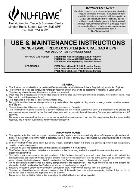
IMPORTANT NOTE<br />
Simulated crushed rock, simulated pebbles, simulated<br />
logs, or simulated driftwood, manufactured from<br />
special materials, are supplied with this appliance.<br />
Do not use real crushed rock, pebbles, logs or<br />
driftwood, as this is dangerous. If the simulated<br />
crushed rock, simulated pebbles, simulated logs or<br />
simulated driftwood need renewing please obtain<br />
suitable replacements from a<br />
<strong>Nu</strong>-<strong>Flame</strong> stockist.
USE & MAINTAINENCE INSTRUCTIONS (continued)<br />
USING THE INFRA RED CONTROL SYSTEM<br />
Control can only be achieved if the transmitter is pointed at the infra-red sensor located<br />
at the right hand end of the Fireboxx towards the front.<br />
a. Ignition<br />
Simultaneously press and hold the star/up arrow button and the small lower button<br />
(linked by arrow) until a short acoustic signal confirms that the sequence has begun,<br />
then release the buttons. Continuous audible signals confirm that ignition is in<br />
progress. When pilot ignition is confirmed the motor will open the valve to maximum<br />
flame height – this takes about 30 seconds.<br />
b. <strong>Flame</strong> Height Adjustment<br />
Press the down arrow button until the flame height is at the desired position. If you<br />
try to go beyond the preset low flame minimum height the fire will turn off leaving the<br />
pilot burner alight (This is the standby position). You will learn from experience the<br />
minimum preset flame height.<br />
To relight the fire from the standby position, or to increase the flame height from low<br />
flame, press the up arrow and lower left button (linked by arrow). Please note that<br />
you can have the flame height anywhere between maximum and preset low. For<br />
fine adjustment simply tap the up or down arrows.<br />
c. To Switch Off<br />
Press the off button on the handset<br />
d. Manual Off Switch<br />
If your handset is mislaid, or for some reason the batteries fail while the fire is<br />
running you can turn the fire off with the on/off switch located at the front right hand<br />
corner of the fire. This switch interrupts the thermocouple current to the control<br />
system and shuts down the fire immediately. This switch must be put back into the<br />
on position to relight the fire.<br />
e. General<br />
Battery replacement is recommended at the beginning of each heating season, or when an acoustic error message sounds<br />
during ignition.<br />
Error Message – Long signals (0.8 second tone – 0.2 second break) during ignition – probable cause - batteries in receiver<br />
are nearly discharged.<br />
Error Message – 5 second continuous tone – probable cause – cable disconnected or on/off switch on valve is in off position<br />
Batteries Receiver - 4 x AA good quality alkaline<br />
Handset – 1 x PP3 good quality alkaline<br />
f. Resetting the Mertik Maxitrol Logic Circuits (Infrared control)<br />
It sometimes happens that (such as when the handset buttons are pressed out of sequence) the fire stops working because<br />
the logic circuits get confused and need to be reset. To do this, simply remove the 4 x AA batteries from the box (do not use<br />
metal tools to do this), wait for 1 minute and then replace the batteries. Wait for another minute and then point the handset at<br />
the receiver eye and press the off button. Wait for another half minute and then start the fire as normal. If the fire does not<br />
start repeat the resetting procedure. If the fire still does not work, the problem lies elsewhere.<br />
Note: If an extended battery box has been supplied, and the lead has been unclipped from the battery box, do not let the lead<br />
terminals touch any metal parts, because voltage is still stored in the capacitors, which can cause a short circuit.<br />
CLEANING THE FIRE<br />
a. Do not use a vacuum cleaner to clean the appliance.<br />
b. Gently remove the simulated pebbles, logs or driftwood one by one & remove soot deposits with a soft brush.<br />
c. The firebed granules should be as shown on the drawing on page 5. If they are not top up as required. Ensure that the<br />
granules are not obstructing the pilot cover assembly. If any further granules are required use only those supplied by<br />
<strong>Nu</strong>-<strong>Flame</strong>.<br />
d. Pebble, log & driftwood effect fires: Re-lay as shown on the relevant drawing. Do not add more simulated pebbles, logs<br />
or driftwood or change the firebed layout in any way.<br />
Page 2 of 15
®<br />
RECORD DATA TO BE COMPLETED & KEPT BY USER:<br />
PLACE OF PURCHASE ..................................................................………………………. DATE ……....................<br />
ADDRESS & TEL. NO. .…...……………….......................................….............................................................................<br />
.................................................................................................................................………………………..........…………<br />
.................................................................................................................................………………………..........…………<br />
APPLIANCE SERIAL NO. ..............................................<br />
INSTALLED BY ........................................…………………………………. CORGI REG. NO ...................................<br />
INSTALLATION & SERVICING INSTRUCTIONS<br />
FOR NU-FLAME FIREBOXX SYSTEM (NATURAL GAS & LPG)<br />
FOR DECORATIVE PURPOSES ONLY<br />
NATURAL GAS MODELS: F350N fitted with an N2R (350) Evolution Burner<br />
F500N fitted with an N5R (500) Evolution Burner<br />
F720N fitted with N4(x2) (720) Evolution Burners<br />
LPG MODELS: F350L fitted with an L2R (350) Evolution Burner<br />
F500L fitted with an L5R (500) Evolution Burner<br />
F720L fitted with L4(x2) (720) Evolution Burners<br />
THIS APPLIANCE MUST BE INSTALLED & SERVICED BY A PROPERLY QUALIFIED (IN<br />
ACCORDANCE WITH LOCAL & NATIONAL CODES) INSTALLATION ENGINEER.<br />
IMPORTANT:<br />
BEFORE PROCEEDING WITH THE INSTALLATION READ THESE INSTRUCTIONS CAREFULLY. THESE INSTRUCTIONS<br />
SHOULD BE KEPT IN A SAFE PLACE FOR FUTURE REFERENCE AND SERVICING DETAILS.<br />
PRIOR TO INSTALLATION ENSURE THAT THE GAS TYPE & PRESSURE ARE AS STATED ON APPLIANCE DATA PLATE.<br />
SIMULATED CRUSHED ROCK, SIMULATED PEBBLES, SIMULATED LOGS OR SIMULATED DRIFTWOOD,<br />
MANUFACTURED FROM SPECIAL MATERIALS, ARE SUPPLIED WITH THIS APPLIANCE. DO NOT USE REAL<br />
PEBBLES, LOGS OR DRIFTWOOD, AS THIS IS DANGEROUS. IF THE SIMULATED CRUSHED ROCK, SIMULATED<br />
PEBBLES, SIMULATED LOGS OR SIMULATED DRIFTWOOD NEED RENEWING PLEASE OBTAIN SUITABLE<br />
REPLACEMENTS FROM A NU-FLAME STOCKIST.<br />
GAS TYPE: SEE DATA PLATE.<br />
BURNER: EVOLUTION MOULDED VERMICULITE<br />
APPLIANCE DATA<br />
FLAME SAFETY: OXYGEN DEPLETION & FLAME FAILURE DEVICE STANDARD TO ALL MODELS.<br />
APPLIANCE INLET WORKING PRESSURE: SEE DATA PLATE.<br />
IGNITION: FROM REMOTE CONTROL SYSTEM<br />
INLET CONNECTION: 8MM COMPRESSION FITTING.<br />
NETT HEAT INPUT: SEE DATA PLATE.<br />
Page 3 of 15
INSTALLATION & SERVICING INSTRUCTIONS (continued)<br />
Natural Gas Models (For G20 Gas*)<br />
Fireboxx Burner Injector kW Input Net Burner Pressure<br />
Model Model Flue Classes Category Gas Size High <strong>Flame</strong> (High <strong>Flame</strong>)<br />
F350N N2R (400) Classes 1 & 2 I2H G20 82/400 5.3 13.6 mbar<br />
F500N N5R (500) Classes 1 & 2 I2H G20 82/500 6.7 15.5mbar<br />
F720N N4(x2) (720) Class 1 Only I2H G20 2 x 82/400 8.2 9.7mbar<br />
LPG Models (For G31 Gas)<br />
Fireboxx Burner Injector kW Input Net Burner Pressure<br />
Model Model Flue Classes Category Gas Size High <strong>Flame</strong> (High <strong>Flame</strong>)<br />
F350L L2R (350) Classes 1 & 2 I3P G31 92/170 5.2 33mbar<br />
F500L L5R (500) Classes 1 & 2 I3P G31 92/260 5.4 13mbar<br />
F720L L4(x2) (720) Class 1 Only I3P G31 2 x 92/170 8.3 23mbar<br />
FLUE REQUIREMENTS<br />
a. Ensure that the builders opening, flue & hearth for the appliance are constructed from non-combustible materials, and<br />
conform to National Regulations and Local Codes.<br />
Fireboxx Models F350N, F350L, F500N & F500L require a minimum flue diameter of 125mm or equivalent area<br />
(Class 2).<br />
Fireboxx Models F720N, & F720L require a minimum flue diameter of 175mm or equivalent area (Class 1).<br />
b. The flue MUST be free of any obstructions. Any dampers or restrictors MUST be removed. Some dampers are impractical to<br />
remove; therefore they must be fixed in some way in the OPEN position.<br />
c. The chimney/flue should be swept prior to installation of the appliance.<br />
d. Ensure that only one fireplace is served by the flue system.<br />
e. Ensure that the chimney/flue is continuous from inlet to termination.<br />
f. Ensure that the chimney/flue is structurally sound, so that combustion products do not come into contact with combustible<br />
material outside the chimney.<br />
g. Ensure that there is a smooth tapered transition from the fireplace opening to the flue.<br />
h. If the appliance is to be installed under a canopy, or is open on both sides, great care must be taken to ensure the<br />
configuration is correct. If in any doubt seek expert advice.<br />
i. CHECK FLUE PULL. Apply a smoke match to the flue opening at hearth level and observe smoke. If there is a definite flow<br />
into the flue aperture, proceed with installation. If there is not a definite flow into the flue aperture, preheat the flue for<br />
approximately 10 minutes and re-test. If there is still no definite flow towards the flue aperture the flue may need attention. DO<br />
NOT FIT THE APPLIANCE, SEEK EXPERT ADVICE.<br />
ADDITIONAL ROOM VENTILATION<br />
THE CONNECTION, VENTILATION REQUIREMENTS (IF ANY) & INSTALLATION OF THE APPLIANCE MUST BE IN<br />
ACCORDANCE WITH NATIONAL REGULATIONS AND LOCAL CODES. IF IN ANY DOUBT WITH REGARD TO ANY<br />
VENTILATION REQUIREMENTS SEEK EXPERT ADVICE. NOTE. In the UK Model <strong>Nu</strong>mbers F350N, F500N, F350L & F500L do<br />
not require additional room ventilation. In Eire all Evolution Fires require additional room ventilation. For other countries refer to<br />
National Regulations and Local Codes.<br />
APPLIANCE LOCATION<br />
a. The Fireboxx can be hearth mounted, shelf mounted, or flush mounted for Hole in the Wall applications using the support<br />
flanges supplied loose in the box, together with the fixing screws needed.<br />
b. Ensure that no naked flame or incandescent part of the fire bed projects beyond the vertical plane of the fireplace opening.<br />
Page 4 of 15
INSTALLATION & SERVICING INSTRUCTIONS (continued)<br />
HEARTHS<br />
BS5871 and Building Regulations Document J call for a hearth to be provided if any flame, or incandescent part of the firebed is<br />
less than 225mm vertically above any carpet or floor covering. Where there is no carpet or floor covering in place, it is<br />
recommended that the 225mm distance be increased to 300mm, to make allowance for any future floor covering.<br />
INSTALLATION OF THE APPLIANCE<br />
Having ensured that the appliance application is correct and the requirements of the flue specification, ventilation demands and<br />
the gas supply are correct, proceed with the installation and assembly as follows:<br />
a. In common with all other gas appliances, dirt and debris in the gas system can block the valve and gas injectors on<br />
this appliance, and faults caused by this are not covered by the guarantee. If you suspect that there is dirt and/or<br />
debris in the gas distribution system, fit a filter in the pipeline, before the burner gas installation connection.<br />
b. Do not use jointing compound on any compression fittings on the burner or the control valve. The use of jointing compound on<br />
the compression fittings on this appliance will possibly invalidate the guarantee, as it can get into the control valve mechanism<br />
and cause it to malfunction.<br />
c. Ensure that there is an isolating valve in the gas supply line near the appliance.<br />
d. Check that all gas connections are sound. The appliance has been factory tested; however the connections may have been<br />
disturbed in transit or storage.<br />
e. Open fires are a hazard; it is recommended that a guard be fitted to provide protection for children, the elderly, or infirm (see<br />
National Regulations if any).<br />
f. Do not adjust or put out of action the spillage monitoring system (oxypilot), or change any of its parts.<br />
g. <strong>Use</strong> only original manufacturer's parts if any replacements are needed.<br />
h. If there is any concern about a pressure zone causing downdraught in certain wind conditions a suitable chimney cowl should<br />
be fitted<br />
i. Place the firebox in position, with the pilot to the rear, and remove the lift-out top grille.<br />
j. Fit the 4 # AA batteries in the battery box located at the left hand end of the Fireboxx, and replace the battery box with its<br />
connector lead connection at the top. Ensure that the lead wire does not contact the end of the burner pan by tucking the lead<br />
wires between the battery box and the left hand end of the Fireboxx, as shown on the drawing on page 6.<br />
k. Run the gas supply through the grommeted hole in the bottom of the Fireboxx and connect it to the test point elbow inlet<br />
connection at the right hand end of the burner.<br />
l. Ensure the restrictor screw in the test point elbow is in the fully open position.<br />
m. Carry out a gas soundness check. You can use the test point connection on the test point elbow inlet connection for your<br />
manometer. (Inlet Pressure 20mbar.)<br />
n. Replace the top grille and position the battery cover plate as shown in the drawing on page 6.<br />
ARRANGEMENT OF THE FUEL BED FILL<br />
a. The burner tray is supplied with the moulded burner already fixed in place. Fill the space left in the tray with vermiculite<br />
granules to just below the top of the burner tray taking care not to allow any vermiculite particles to drop into the gas outlet<br />
slots in the moulded burner unit. We suggest covering the slots with Sellotape or similar before filling with vermiculite. Level<br />
the granules to give an even layer over the burner tray. Ensure that pilot assembly is cleared of vermiculite granules, and<br />
remove the Sellotape or similar.<br />
b. Cover the burner block and the loose vermiculite with 5-7mm (approximately a single layer) of the simulated crushed rock, and<br />
shape off to the edge of the tray (see drawing below).<br />
c. The Fireboxx can be used with just the simulated crushed rock as the firebed. <strong>Nu</strong>-<strong>Flame</strong> can also supply premium quality<br />
simulated pebbles, simulated logs or simulated driftwood specially designed to be used with the Fireboxx and these can be<br />
positioned on top of the simulated crushed rock to give a range of different looks. If using these items please refer to the<br />
appropriate layout drawing located at the back of these <strong>instructions</strong>.<br />
Page 5 of 15
Page 6 of 15
INSTALLATION & SERVICING INSTRUCTIONS (continued)<br />
THERMATRONIC INFRA RED CONTROL SYSTEM (MERTIK MAXITROL)<br />
IMPORTANT NOTES<br />
Temperature Limits of Electronic Components<br />
a. It is of great importance and absolutely necessary to ensure that the electronic control system components temperature does<br />
not rise above 60ºC, and assuming a normal room temperature, the temperature of the electronic components should not rise<br />
too much above 35 ºC. This allows a big margin of safety<br />
b. It is also very important to ensure that the fire is not subjected to intermittent or permanent flue downdraught, which can blow<br />
flames/gas down to the underside of the burner and cause overheating of the electronics<br />
Dampness<br />
a. All electronic equipment is sensitive to dampness and high humidity.<br />
b. The Thermatronic equipment must be installed in a completely dry place that does not access directly to outside air.<br />
c. If the fireplace has recently been rendered it must be allowed to completely dry out before the electronic equipment is<br />
installed.<br />
d. It is possible that dampness has occurred during storage of the appliance, so as a precaution we suggest placing the Fireboxx<br />
in a warm dry place for a while before installation<br />
Resetting the Mertik Maxitrol Logic Circuits (Infrared control)<br />
It sometimes happens that (such as when the handset buttons are pressed out of sequence) the fire stops working because<br />
the logic circuits get confused and need to be reset. To do this, simply remove the 4 x AA batteries from the box (do not use<br />
metal tools to do this), wait for 1 minute and then replace the batteries. Wait for another minute and then point the handset at<br />
the receiver eye and press the off button. Wait for another half minute and then start the fire as normal. If the fire does not<br />
start repeat the resetting procedure. If the fire still does not work, the problem lies elsewhere.<br />
Note: If an extended battery box has been supplied, and the lead has been unclipped from the battery box, do not let the lead<br />
terminals touch any metal parts, because voltage is still stored in the capacitors, which can cause a short circuit.<br />
General<br />
a. The Thermatronic Control System is a battery operated gas fire control system that uses a microprocessor to provide the<br />
working sequences needed by the fire, and when used with an oxypilot has all the safety features required by law and CE<br />
approval.<br />
b. Commands are accepted by the microprocessor when buttons are pressed. An audible beep means that the command is<br />
received, and the push button should immediately be released.<br />
Page 7 of 15
Page 8 of 15
Page 9 of 15
INSTALLATION & SERVICING INSTRUCTIONS (continued)<br />
Important Notes<br />
a. This appliance is fitted with an oxygen depletion sensing system which automatically shuts off the gas supply to the main<br />
burner if the oxygen level in the room is depleted, due to lack of air or an obstructed flue.<br />
b. If the fire shuts down for any reason, attempt to re-start it. If there is a continuing problem call in a specialist engineer.<br />
c. There are no user replaceable parts in this appliance except the batteries.<br />
COMMISSIONING THE FIRE<br />
a. Close all doors and windows, check operation of controls and burn for 5 minutes. Test for spillage of the flue products using a<br />
smoke match. If there is a small amount of spillage, run the fire for a further 10 minutes and re-test for spillage. If there is still<br />
spillage after the second test, DISCONNECT THE FIRE AND SEEK EXPERT ADVICE.<br />
NOTE. If there are extractor fans in the room or adjacent rooms, these must be running at full speed setting with all<br />
interconnecting doors left OPEN.<br />
b. A smell may be experienced when the appliance is first commissioned. This is due to the new components of the fire. These<br />
odours will cease after the first few hours of burning.<br />
SPECIAL NOTES<br />
a. This fire should be serviced every 12 months to ensure safe operation.<br />
b. Servicing and spares are available from your stockist.<br />
c. The fire may smell for the first few hours. This is due to the newness of the components and will cease in a few hours. If it<br />
does not consult your dealer straight away.<br />
d. Open fires are a hazard; it is recommended that a guard be fitted to provide protection for children, the elderly, or infirm (see<br />
National Regulations, if any).<br />
e. This appliance must never be cleaned with a vacuum cleaner.<br />
f. Debris and soot should be cleaned from the fire with a soft brush.<br />
g. Regularly check that the fixed air supply (if applicable) is free of any obstructions.<br />
h. IF THE FIREBED MATERIAL IS REPLACED USE ONLY MATERIAL SUPPLIED BY THE MANUFACTURER. FINER GRANULE<br />
SIZES ARE NOT SUITABLE.<br />
Note. SEEK EXPERT ADVICE IF YOU ARE UNSURE OF ANY POINTS REGARDING THE SAFE USE OF THIS APPLIANCE.<br />
FAULT FINDING GUIDE. SYMPTOMS AND POSSIBLE CAUSES<br />
1. NO SPARK<br />
Pilot light damaged, or too far away from Electrode, or too close.<br />
Electrode retaining lock nut has become loose, and needs to be tightened.<br />
Ignition lead has become detached from electrode and needs reconnecting.<br />
Electrode is damaged and needs to be replaced.<br />
Soot on the Pilot assembly and shorting spark. Clean this area with a soft brush.<br />
Faulty ignition lead. Replace.<br />
2. SPARK IS VISIBLE BUT PILOT WILL NOT LIGHT<br />
Check that there is gas to the appliance.<br />
Ensure that isolating valve or restrictor elbow is in the OPEN position.<br />
Valve inlet has become blocked with debris. Clean.<br />
Pilot injector blocked. Clean.<br />
3. PILOT FLAME SHORTENS, OR GOES OUT, WHEN MAIN BURNER LIGHTS<br />
This indicates insufficient gas pressure to the appliance. Check for debris obstruction.<br />
Check that there are no acute bends in the supply pipe and ensure that the correct diameter supply pipe has been used.<br />
Check pressure setting.<br />
NOTE. If the appliance has been connected to a supply servicing another appliance the supply pipe may not have sufficient<br />
capacity to serve both appliances. Seek advice.<br />
4. PILOT GOES OUT AT REGULAR INTERVALS<br />
Check that thermocouple is not loose. (It should only be nipped up as it is just an electrical connection.)<br />
Thermocouple is damaged and needs replacing.<br />
Thermocouple operated magnetic valve faulty – replace gas valve.<br />
5. BLUE FLAME<br />
It normally takes 20 minutes for the fire to reach correct working temperature, by which time most of the blue flame<br />
should have gone. Continuous blue flame is caused by poor coal layout or excessive updraughft of the flue. Seek advice<br />
from your stockist.<br />
Poor gas pressure will also cause blue flame. Check gas pressure.<br />
6. POOR FLAME PICTURE<br />
Check gas pressure.<br />
Ensure that there are no obvious obstructions to gas supply pipe.<br />
Re-lay the simulated pebbles logs or driftwood as shown in the relevant drawing.<br />
Page 10 of 15
INSTALLATION & SERVICING INSTRUCTIONS (continued)<br />
SERVICING INSTRUCTIONS<br />
IMPORTANT: Turn OFF gas supply before servicing commences.<br />
1. Remove all debris and dust from fire. DO NOT USE A VACUUM CLEANER TO DO SO.<br />
2. If you have them on your fire remove any simulated pebbles, logs or driftwood from burner tray and gently dust off with a soft<br />
brush.<br />
3. Disconnect gas supply and remove burner tray assembly.<br />
4. Carefully remove and retain the firebed material. IF IT IS TO BE REPLACED USE ONLY MATERIAL SUPPLIED BY THE<br />
MANUFACTURER. FINER GRANULE SIZES ARE NOT SUITABLE.<br />
5. Check Pilot and Gas valve assembly for gas soundness. Continue with service as required.<br />
6. When replacing the vermiculite and re-laying the firebed material please refer to the ARRANGEMENT OF FUEL BED FILL<br />
section commencing of these <strong>instructions</strong>.<br />
<strong>Nu</strong>-<strong>Flame</strong> Warranty and Repair Procedure<br />
<strong>Nu</strong>-<strong>Flame</strong> fires are guaranteed for 1 year from the date of purchase. During that time our guarantee is to repair at our option, or replace<br />
at no charge a fire that proves to have faulty components or workmanship.<br />
Telephone Help Line. In the event of a problem with a fire the first course of action should be to telephone our technical department on<br />
020 8254 6802 during normal working hours 9 - 5.30 Monday - Friday (closed 1 - 1.30). If appropriate this should be done before the<br />
installer leaves site as we may well be able to resolve the problem over the phone and in any event it will save the installer a return visit<br />
to site. If we are not able to resolve the problem over the phone we will ask you to return the fire, and will log your details and give you a<br />
return reference number.<br />
Return The Fire. It is a condition of the warranty that if we request you to return the fire to the factory, at the outset of any problem, you<br />
do so. This is both for safety reasons and due to the fact that we have the trained staff and necessary spares to carry out the repairs.<br />
The burner can then be thoroughly inspected and any signs of installation faults can be reported back to you. After any repair work is<br />
carried out the flow rates can be checked and re-set if necessary in order to fully comply with CE approval.<br />
During the first year we may, at our discretion, pay a fixed amount of £10 for return carriage to the factory, plus £40 for removal etc. and<br />
£50 for refitting (all plus VAT) for any fire that, after examination by us, proves to have faulty components or workmanship. The fire will<br />
then be returned to a mainland UK address free of charge usually within 10 working days of our receiving it.<br />
Under no circumstances should any attempt be made to repair the burner on site without our express knowledge and approval during the<br />
warranty period.<br />
This guarantee is given subject to the following provisions:<br />
1. That the installation is carried out by a CORGI registered installer (we may require their registration details).<br />
2. That the appliance is installed and used in accordance with our Installation & <strong>Use</strong>r <strong>instructions</strong>.<br />
3. That the gas supply pressure at the appliance is not more than 3mbar below the gas pressure stated on the data plate when the<br />
appliance is running on high flame, with any other major gas appliances also running.<br />
4. That the fireplace and flue system conform to relevant local codes, building regulations and British Standards.<br />
5. This Guarantee is not transferable and relates to the original installation only.<br />
6. The appliance has not been subject to misuse or accident or been modified or repaired by any person other than the authorised<br />
employee or authorised representative of <strong>Nu</strong>-<strong>Flame</strong> Ltd.<br />
7. The Record Data section on the front of the Installation & Servicing Instructions is to be completed on installation.<br />
8. <strong>Nu</strong>-<strong>Flame</strong> Ltd accepts no liability for any consequential loss or damage arising from the use or failure of the product or any<br />
information provided, including, but not limited to, economic or financial loss, damage to peripheral equipment or products, loss of<br />
use, productivity or time.<br />
9. That the serial no. data plate on the burner is intact.<br />
This guarantee in no way reduces your statutory rights.<br />
Chargeable Repairs During and After the Warranty Period<br />
If a repair is chargeable during the warranty period, due to installation faults we will inform you and where possible give you a quote, or if<br />
this is not possible, a price guide before starting work. We cannot always give a firm cost until we commence the repair as it is not<br />
always possible to tell which components have been damaged.<br />
Page 11 of 15
MODEL F350<br />
LAYOUT FOR RECOMMENDED F350<br />
SIMULATED PEBBLE SET<br />
AVAILABLE FROM NU-FLAME<br />
Identify the simulated pebbles in the set by comparing them<br />
to the drawings below and then lay them in accordance with<br />
the pattern shown.<br />
It is important to leave spaces of 15mm - 20mm between<br />
the simulated pebbles to ensure good secondary aeration.<br />
Do not overload the fire as it will spoil the appearance of the<br />
fire and cause sooting. Do not put more than 2 layers of<br />
simulated pebbles on any fire. Do not add further<br />
simulated pebbles.<br />
BASE LAYER<br />
Do not cover any part of the gas outlet slots with<br />
the base layer of simulated pebbles. The gas<br />
outlet slots will be under the simulated crushed<br />
rock firebed, but will be easy to locate.<br />
Ensure that the ventilation slots in the top grille<br />
are not obscured by the base layer of simulated<br />
pebbles.<br />
TOP LAYER<br />
Run the fire for approximately 10 minutes and then, if<br />
required, adjust simulated pebbles to give desired effect.<br />
Page 12 of 15<br />
MODEL F350<br />
LAYOUT FOR RECOMMENDED F350<br />
SIMULATED LOG OR DRIFTWOOD<br />
SET AVAILABLE FROM NU-FLAME<br />
Identify the simulated logs/driftwood in the set by comparing<br />
them to the drawings below and then lay them in<br />
accordance with the pattern shown.<br />
Do not overload the fire as it will spoil the appearance of the<br />
fire and cause sooting. Do not put more than 2 layers of<br />
simulated logs/driftwood on any fire. Do not add further<br />
simulated logs/driftwood.<br />
BASE LAYER<br />
Lay the base layer of simulated logs/driftwood in<br />
such a way as to minimise the area of gas outlet<br />
slots covered. These slots will be under the<br />
simulated crushed rock firebed, but will be easy to<br />
locate. Note: The branch of one base layer log are<br />
resting on another log so the slots are less<br />
covered than they look in the above illustration.<br />
Ensure that the ventilation slots in the top grille<br />
are not obscured by the base layer of simulated<br />
logs/driftwood.<br />
TOP LAYER<br />
Run the fire for approximately 10 minutes and then, if<br />
required, adjust simulated logs or driftwood to give desired<br />
effect
MODEL F500<br />
LAYOUT FOR RECOMMENDED F500<br />
SIMULATED PEBBLE SET<br />
AVAILABLE FROM NU-FLAME<br />
Identify the simulated pebbles in the set by comparing them<br />
to the drawings below and then lay them in accordance with<br />
the pattern shown.<br />
It is important to leave spaces of 15mm - 20mm between<br />
the simulated pebbles to ensure good secondary aeration.<br />
Do not overload the fire as it will spoil the appearance of the<br />
fire and cause sooting. Do not put more than 2 layers of<br />
simulated pebbles on any fire. Do not add further<br />
simulated pebbles.<br />
BASE LAYER<br />
Do not cover any part of the gas outlet slots with<br />
the base layer of simulated pebbles. The gas<br />
outlet slots will be under the simulated crushed<br />
rock firebed, but will be easy to locate.<br />
Ensure that the ventilation slots in the top grille<br />
are not obscured by the base layer of simulated<br />
pebbles.<br />
TOP LAYER<br />
Run the fire for approximately 10 minutes and then, if<br />
required, adjust simulated pebbles to give desired effect.<br />
Page 13 of 15<br />
MODEL F500<br />
LAYOUT FOR RECOMMENDED F500<br />
SIMULATED LOG OR DRIFTWOOD<br />
SET AVAILABLE FROM NU-FLAME<br />
Identify the simulated logs/driftwood in the set by comparing<br />
them to the drawings below and then lay them in<br />
accordance with the pattern shown.<br />
Do not overload the fire as it will spoil the appearance of the<br />
fire and cause sooting. Do not put more than 2 layers of<br />
simulated logs/driftwood on any fire. Do not add further<br />
simulated logs/driftwood.<br />
BASE LAYER<br />
Lay the base layer of simulated logs/driftwood in<br />
such a way as to minimise the area of gas outlet<br />
slots covered. These slots will be under the<br />
simulated crushed rock firebed, but will be easy to<br />
locate. Note: The branches of some base layer<br />
logs are resting on other logs so the slots are less<br />
covered than they look in the above illustration.<br />
Ensure that the ventilation slots in the top grille<br />
are not obscured by the base layer of simulated<br />
logs/driftwood.<br />
TOP LAYER<br />
Run the fire for approximately 10 minutes and then, if<br />
required, adjust simulated logs or driftwood to give desired<br />
effect
MODEL F720<br />
LAYOUT FOR RECOMMENDED F720<br />
SIMULATED PEBBLE SET<br />
AVAILABLE FROM NU-FLAME<br />
Identify the simulated pebbles in the set by comparing them<br />
to the drawings below and then lay them in accordance with<br />
the pattern shown.<br />
It is important to leave spaces of 15mm - 20mm between<br />
the simulated pebbles to ensure good secondary aeration.<br />
Do not overload the fire as it will spoil the appearance of the<br />
fire and cause sooting. Do not put more than 2 layers of<br />
simulated pebbles on any fire. Do not add further<br />
simulated pebbles.<br />
BASE LAYER<br />
Do not cover any part of the gas outlet slots with<br />
the base layer of simulated pebbles. The gas<br />
outlet slots will be under the simulated crushed<br />
rock firebed, but will be easy to locate.<br />
Ensure that the ventilation slots in the top grille<br />
are not obscured by the base layer of simulated<br />
pebbles.<br />
TOP LAYER<br />
Run the fire for approximately 10 minutes and then, if<br />
required, adjust simulated pebbles to give desired effect.<br />
Page 14 of 15<br />
MODEL F720<br />
LAYOUT FOR RECOMMENDED F720<br />
SIMULATED LOG OR DRIFTWOOD<br />
SET AVAILABLE FROM NU-FLAME<br />
Identify the simulated logs/driftwood in the set by comparing<br />
them to the drawings below and then lay them in<br />
accordance with the pattern shown.<br />
Do not overload the fire as it will spoil the appearance of the<br />
fire and cause sooting. Do not put more than 2 layers of<br />
simulated logs/driftwood on any fire. Do not add further<br />
simulated logs/driftwood.<br />
BASE LAYER<br />
Lay the base layer of simulated logs/driftwood in<br />
such a way as to minimise the area of gas outlet<br />
slots covered. These slots will be under the<br />
simulated crushed rock firebed, but will be easy to<br />
locate. Note: The branches of some base layer<br />
logs are resting on other logs so the slots are less<br />
covered than they look in the above illustration.<br />
Ensure that the ventilation slots in the top grille<br />
are not obscured by the base layer of simulated<br />
logs/driftwood.<br />
TOP LAYER<br />
Run the fire for approximately 10 minutes and then, if<br />
required, adjust simulated logs or driftwood to give desired<br />
effect
GENERAL PEBBLE LAYOUT<br />
PRINCIPLES FOR USING SIMULATED<br />
PEBBLE SET THAT IS NOT SPECIFIC TO THE<br />
FIREBOX BURNER<br />
Due to the various burner sizes and simulated pebble<br />
shapes & sizes there is not an exact pattern. These layouts<br />
are a guide to illustrate the general principles.<br />
It is important to leave spaces of 15mm - 20mm between<br />
the simulated pebbles to ensure good secondary aeration.<br />
Do not overload the fire as it will spoil the appearance of the<br />
fire and cause sooting.<br />
Do not put more than 2 layers of simulated pebbles on any<br />
fire.<br />
Note: If using simulated pebbles that are supplied in<br />
standard sized sets it might not be necessary to use all the<br />
simulated pebbles supplied.<br />
BASE LAYER<br />
Do not cover any part of the gas outlet slots with the<br />
base layer of simulated pebbles. The gas outlet slots<br />
will be under the simulated crushed rock firebed, but<br />
will be easy to locate.<br />
Ensure that the ventilation slots in the top grille are<br />
not obscured by the base layer of simulated pebbles.<br />
TOP LAYER<br />
Run the fire for approximately 10 minutes and then, if<br />
required, adjust simulated pebbles to give desired effect.<br />
If sooting occurs remove some simulated pebbles and/or<br />
space the components out more.<br />
Page 15 of 15<br />
GENERAL LOG/DRIFTWOOD LAYOUT<br />
PRINCIPLES FOR USING SIMULATED LOGS<br />
OR DRIFTWOOD SET THAT IS NOT SPECIFIC<br />
TO THE FIREBOX BURNER<br />
Due to the various burner sizes and simulated<br />
logs/driftwood shapes & sizes there is not an exact pattern<br />
These layouts are a guide to illustrate the general principles.<br />
It is important to leave spaces of 15mm – 20mm between<br />
the simulated logs/driftwood to ensure good secondary<br />
aeration. Do not overload the fire as it will spoil the<br />
appearance of the fire and cause sooting.<br />
Do not put more than 2 layers of simulated logs or simulated<br />
driftwood on any fire.<br />
Note: If using simulated logs/driftwood that are supplied in<br />
standard sized sets it might not be necessary to use all the<br />
simulated logs/driftwood supplied.<br />
BASE LAYER<br />
Lay base layer of simulated logs/driftwood in such a<br />
way as to minimise the area of gas outlet slots<br />
covered. These slots will be under the simulated<br />
crushed rock firebed, but will be easy to locate.<br />
Ensure that the ventilation slots in the top grille are<br />
not obscured by the base layer of simulated<br />
logs/driftwood.<br />
TOP LAYER<br />
Run the fire for approximately 10 minutes and then, if<br />
required, adjust simulated logs or driftwood to give desired<br />
effect<br />
If sooting occurs remove some simulated logs/driftwood<br />
and/or space the components out more.