06-086-098 Weld ring gaskets.pmd - Kempchen.de
06-086-098 Weld ring gaskets.pmd - Kempchen.de
06-086-098 Weld ring gaskets.pmd - Kempchen.de

You also want an ePaper? Increase the reach of your titles
YUMPU automatically turns print PDFs into web optimized ePapers that Google loves.
<strong>06</strong><br />
86<br />
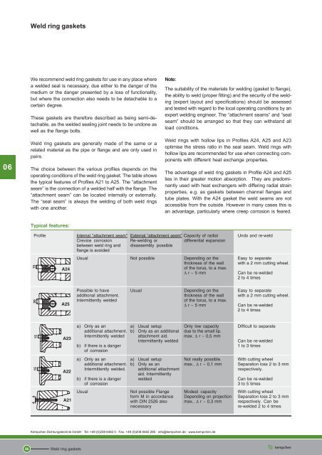
<strong>Weld</strong> <strong>ring</strong> <strong>gaskets</strong><br />
We recommend weld <strong>ring</strong> <strong>gaskets</strong> for use in any place where<br />
a wel<strong>de</strong>d seal is necessary, due either to the danger of the<br />
medium or the danger presented by a loss of functionality,<br />
but where the connection also needs to be <strong>de</strong>tachable to a<br />
certain <strong>de</strong>gree.<br />
These <strong>gaskets</strong> are therefore <strong>de</strong>scribed as being semi-<strong>de</strong>tachable,<br />
as the wel<strong>de</strong>d sealing joint needs to be undone as<br />
well as the flange bolts.<br />
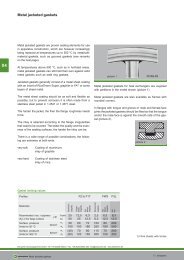
<strong>Weld</strong> <strong>ring</strong> <strong>gaskets</strong> are generally ma<strong>de</strong> of the same or a<br />
related material as the pipe or flange and are only used in<br />
pairs.<br />
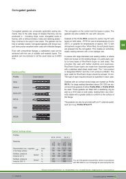
The choice between the various profiles <strong>de</strong>pends on the<br />
operating conditions of the weld <strong>ring</strong> gasket. The table shows<br />
the typical features of Profiles A21 to A25. The “attachment<br />
seam” is the connection of a wel<strong>de</strong>d half with the flange. The<br />
“attachment seam” can be located internally or externally.<br />
The “seal seam” is always the welding of both weld <strong>ring</strong>s<br />
with one another.<br />
Typical features:<br />
Profile Internal "attachment seam" External “attachment seam” Capacity of radial Undo and re-weld<br />
Crevice corrosion Re-welding or differential expansion<br />
between weld <strong>ring</strong> and<br />
flange is avoi<strong>de</strong>d<br />
disassembly possible<br />
Usual Not possible Depending on the Easy to separate<br />
thickness of the wall<br />
of the torus, to a max.<br />
with a 2 mm cutting wheel.<br />
∆ r ~ 5 mm Can be re-wel<strong>de</strong>d<br />
2 to 4 times<br />
<strong>Kempchen</strong> Dichtungstechnik GmbH · Tel. +49 (0)208 8482 0 · Fax. +49 (0)208 8482 285 · info@kempchen.<strong>de</strong> · www.kempchen.<strong>de</strong><br />
<strong>Weld</strong> <strong>ring</strong> <strong>gaskets</strong><br />
Note:<br />
The suitability of the materials for welding (gasket to flange),<br />
the ability to weld (proper fitting) and the security of the welding<br />
(expert layout and specifications) should be assessed<br />
and tested with regard to the local operating conditions by an<br />
expert welding engineer. The “attachment seams” and “seal<br />
seam” should be arranged so that they can withstand all<br />
load conditions.<br />
<strong>Weld</strong> <strong>ring</strong>s with hollow lips in Profiles A24, A25 and A23<br />
optimise the stress ratio in the seal seam. <strong>Weld</strong> <strong>ring</strong>s with<br />
hollow lips are recommen<strong>de</strong>d for use when connecting components<br />
with different heat exchange properties.<br />
The advantage of weld <strong>ring</strong> <strong>gaskets</strong> in Profile A24 and A25<br />
lies in their greater motion absorption. They are predominantly<br />
used with heat exchangers with diffe<strong>ring</strong> radial strain<br />
properties, e.g. as <strong>gaskets</strong> between channel flanges and<br />
tube plates. With the A24 gasket the weld seams are not<br />
accessible from the outsi<strong>de</strong>. However in many cases this is<br />
an advantage, particularly where creep corrosion is feared.<br />
Possible to have Usual Depending on the Easy to separate<br />
additional attachment. thickness of the wall with a 2 mm cutting wheel.<br />
Intermittently wel<strong>de</strong>d of the torus, to a max.<br />
∆ r ~ 5 mm Can be re-wel<strong>de</strong>d<br />
2 to 4 times<br />
a) Only as an a) Usual setup Only low capacity Difficult to separate<br />
additional attachment. b) Only as an additional due to the small lip.<br />
Intermittently wel<strong>de</strong>d attachment aid. max. ∆ r ~ 0,5 mm<br />
Intermittently wel<strong>de</strong>d Can be re-wel<strong>de</strong>d<br />
b) if there is a danger 1 to 3 times<br />
of corrosion<br />
a) Only as an a) Usual setup Not really possible. With cutting wheel<br />
additional attachment. b) Only as an max.. ∆ r ~ 0,1 mm Separation loss 2 to 3 mm<br />
Intermittently wel<strong>de</strong>d. additional attachment<br />
aid. Intermittently<br />
respectively.<br />
b) if there is a danger wel<strong>de</strong>d Can be re-wel<strong>de</strong>d<br />
of corrosion 3 to 5 times<br />
Usual Not possible Flange Mo<strong>de</strong>st capacity With cutting wheel<br />
form M in accordance Depending on projection Separation loss 2 to 3 mm<br />
with DIN 2526 also max.. ∆ r ~ 0,3 mm respectively. Can be<br />
necessary re-wel<strong>de</strong>d 2 to 4 times
<strong>Weld</strong> <strong>ring</strong> <strong>gaskets</strong><br />
In this case we recommend the following profiles: A24H,<br />
A24K, A24KVR and A24N.<br />
All weld <strong>ring</strong> <strong>gaskets</strong> can be combined with additional auxiliary<br />
<strong>gaskets</strong>. These can be useful for various different reasons.<br />
a) The pressure test should be carried out with an auxiliary<br />
gasket without welding.<br />
b) The start or run-up phase should be un<strong>de</strong>rtaken with the<br />
auxiliary gasket, as it is likely to need to be opened several<br />
times.<br />
c) This application is generally in conjunction with the additional<br />
auxiliary gasket. The weld <strong>ring</strong> gasket is only wel<strong>de</strong>d<br />
if the auxiliary gasket fails.<br />
<strong>Weld</strong> <strong>ring</strong> <strong>gaskets</strong> should be fitted so that the weld <strong>ring</strong> halves<br />
lie on top of each other, and parallel to each other and to the<br />
flanges.<br />
If weld <strong>ring</strong> <strong>gaskets</strong> are used with auxiliary <strong>gaskets</strong>, the<br />
flange and bolt calculations must be carried out once for<br />
the weld <strong>ring</strong> gasket with the seal diameter to the outermost<br />
seal seam and once for the auxiliary gasket.<br />
With the use of auxiliary <strong>gaskets</strong>, a gap of 0.3 mm remains<br />
between the weld <strong>ring</strong> gasket halves, <strong>de</strong>pending on the <strong>de</strong>sign.<br />
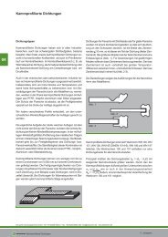
Note:<br />
If there is a build-up of con<strong>de</strong>nsation du<strong>ring</strong> temperature<br />
cycles, this can lead to an uncontrolled increase in pressure<br />
in the torus. This can be avoi<strong>de</strong>d by inserting one or more<br />
grooves (1.5 mm <strong>de</strong>ep, 3 mm wi<strong>de</strong>) into one of the <strong>ring</strong><br />
halves. Please specify the number of grooves when or<strong>de</strong><strong>ring</strong>.<br />
Profile A24H has a weld <strong>ring</strong> half with a convex sealing surface.<br />
The radius conforms to the pressure, temperature and<br />
the material involved. A galvanised coat can be useful.<br />
Profile A24K has a weld <strong>ring</strong> half with a grooved profile, onto<br />
which has been attached a layer approximately 0.5 mm thick<br />
of either PTFE, graphite, silver or FA (fibre in accordance with<br />
DIN 28091), <strong>de</strong>pending on the operating conditions.<br />
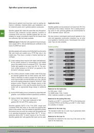
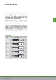
Gasket profiles<br />
Profile Cross-section<br />
A23<br />
A24<br />
A24H<br />
A24K<br />
A25<br />
A24KVR<br />
Profile A24KVR with male and female face joints and grooved<br />
profile as shown in diagram. Depending on the operating<br />
conditions, the layer for this gasket is either PTFE, graphite,<br />
silver or fibre* at a thickness of approximately 0.5 mm.<br />
Grooved profile gasket Profile B27A in a floating-type seal<br />
A24N<br />
Profile A24N has a groove in one weld <strong>ring</strong> half for the addition<br />
of a grooved profile gasket Profile B27A. For the materials<br />
used in the gasket see the section “Grooved <strong>gaskets</strong>”.<br />
The <strong>de</strong>pth of the groove is less than the thickness of the<br />
grooved profile gasket, so that a floating-type seal can be<br />
guaranteed. The groove <strong>de</strong>pth for the use of a grooved profile<br />
gasket = 3,5 -0,1 mm, the thickness of the grooved profile<br />
gasket = 3,6 +0,1 mm.<br />
<strong>Kempchen</strong> Dichtungstechnik GmbH · Tel. +49 (0)208 8482 0 · Fax. +49 (0)208 8482 285 · info@kempchen.<strong>de</strong> · www.kempchen.<strong>de</strong><br />
<strong>Weld</strong> <strong>ring</strong> <strong>gaskets</strong><br />
87<br />
<strong>06</strong>
<strong>06</strong><br />
88<br />
<strong>Weld</strong> <strong>ring</strong> <strong>gaskets</strong><br />
The weld <strong>ring</strong> <strong>gaskets</strong> can also be supplied with a female<br />
face in Profile A24R to receive a grooved profile gasket, so<br />
that if there is any damage to the gasket it can be replaced.<br />
A24R + B27A<br />
The various types of auxiliary <strong>gaskets</strong>, explained in more<br />
<strong>de</strong>tail for A24, are also available for Profile A25 and A23.<br />
Profile A23 is shown with a protective gasket which is in no<br />
way leak-tight.<br />
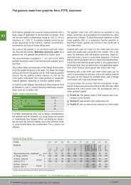
<strong>Weld</strong> <strong>ring</strong> <strong>gaskets</strong> in Profile A22 are, like A23 and A24, 2x15=30<br />
mm thick therefore providing enough room to weld without<br />
special flanges, as shown in the illustration.<br />
Profile A22 Profile A23<br />
This results in large bolt lengths with good sp<strong>ring</strong><br />
suspension. As all weld seams are external, any<br />
irregularities can easily be re-wel<strong>de</strong>d.<br />
Profiles A22 to A22N are predominantly used in pipeline<br />
construction, where the twin flange <strong>de</strong>sign means that no<br />
large differences in strain properties arise when the same<br />
material for the gasket and flange is selected.<br />
<strong>Kempchen</strong> Dichtungstechnik GmbH · Tel. +49 (0)208 8482 0 · Fax. +49 (0)208 8482 285 · info@kempchen.<strong>de</strong> · www.kempchen.<strong>de</strong><br />
<strong>Weld</strong> <strong>ring</strong> <strong>gaskets</strong><br />
A further advantage is that due to the greater thickness an<br />
auxiliary gasket can be provi<strong>de</strong>d, as is explained for A24 -<br />
see weld <strong>ring</strong>s with hollow lips.<br />
Gasket profiles<br />
Profile Cross-section<br />
A22<br />
A22H<br />
A22K<br />
A22KVR<br />
A22N
<strong>Weld</strong> <strong>ring</strong> <strong>gaskets</strong><br />
Membrane <strong>ring</strong>s in accordance with DIN 2695 are each 4<br />
mm thick and should be ma<strong>de</strong> of the same material as the<br />
flange due to the low absorption of radial strain differences.<br />
These <strong>gaskets</strong> are firstly wel<strong>de</strong>d internally to the flange using<br />
an “attachment seam”, and once the flange has been<br />
assembled a “seal seam” is ma<strong>de</strong> externally. Any errors<br />
ma<strong>de</strong> when creating the internal welds* can only be fixed<br />
with great difficulty.<br />
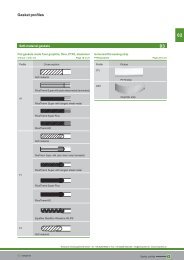
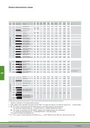
Gasket profile<br />
Profile Cross-section<br />
A21<br />
First check if there is sufficient room to make the seal weld or<br />
if bevelled flanges of the type Form M in accordance with DIN<br />
2526 will be required.<br />
Membrane weld <strong>ring</strong> <strong>gaskets</strong> in Profile A21K are provi<strong>de</strong>d<br />
with an additional grooved profile. The layers of PTFE, graphite<br />
or silver are approximately 0.5 mm thick and should be<br />
selected according to the operating conditions.<br />
The figure shows Profile A21K as assembled between<br />
flanges of type Form M.<br />
* See note on page 87<br />
Profil A21<br />
Membrane weld <strong>ring</strong> gasket Profile A21<br />
Or<strong>de</strong><strong>ring</strong> example for a membrane weld <strong>ring</strong> gasket Profile<br />
A21 with d 1 =115 mm internal diameter and d2 = 169 mm<br />
external diameter, ma<strong>de</strong> of... 1 ):<br />
Gasket 115 x 169, DIN 2695, 1.5415<br />
Each membrane weld <strong>ring</strong> gasket has two weld halves.<br />
Conforms to DIN 2695 (PN 63 to PN 400) Mo<strong>de</strong>l M<br />
3) d2 at PN<br />
DN d1 63 100 160 250 a. 320 400<br />
80 90 143 149 149 153 153<br />
100 115 169 176 176 179 179<br />
125 142 2<strong>06</strong> 213 213 216 216<br />
150 165 243 248 248 248 248<br />
200 214 305 315 315 315 315<br />
250 264 360 370 370 370 -<br />
300 310 420 430 430 - -<br />
350 340 482 490 - - -<br />
400 386 539 - - - -<br />
to 3200 possible<br />
<strong>Kempchen</strong> Dichtungstechnik GmbH · Tel. +49 (0)208 8482 0 · Fax. +49 (0)208 8482 285 · info@kempchen.<strong>de</strong> · www.kempchen.<strong>de</strong><br />
<strong>Weld</strong> <strong>ring</strong> <strong>gaskets</strong><br />
Dimensions in mm<br />
89<br />
<strong>06</strong>
<strong>06</strong><br />
90<br />
<strong>Weld</strong> <strong>ring</strong> <strong>gaskets</strong><br />
Conforms to DIN 2695 (Class 150 to Class 2500) Mo<strong>de</strong>l M<br />
d2 In class<br />
900<br />
to<br />
DN NPS d1 150 300 600 1500 2500<br />
80 3 92 130 142 142 157 157<br />
100 4 118 167 172 180 187 187<br />
125 5 114 190 208 216 216 216<br />
150 6 170 215 243 246 246 246<br />
200 8 220 272 300 300 300 300<br />
250 10 273 332 354 354 354 354<br />
300 12 322 400 411 411 411 411<br />
350 14 360 440 443 443 443 -<br />
400 16 412 500 500 500 500 -<br />
to 3200 possible<br />
Size d 3 2) for PN (DIN 2695) and Class<br />
1) Specify materials when placing or<strong>de</strong>r.<br />
2) When bevelling the flanges the raised face should be<br />
machined to this size (not required for DN150, 200, 350, 400).<br />
3) Aim for 15 mm membrane protrusion, but at least 10 mm<br />
(maximum size: cent<strong>ring</strong> diameter less than 4 mm).<br />
<strong>Kempchen</strong> Dichtungstechnik GmbH · Tel. +49 (0)208 8482 0 · Fax. +49 (0)208 8482 285 · info@kempchen.<strong>de</strong> · www.kempchen.<strong>de</strong><br />
<strong>Weld</strong> <strong>ring</strong> <strong>gaskets</strong><br />
d 3 2)<br />
Dimensions in mm<br />
PN Class<br />
DN NPS 63 - 400 150 300 600<br />
80 3 123 116 122 122<br />
100 4 149 146 150 -<br />
125 5 186 172 180 -<br />
150 6 218 196 - -<br />
200 8 285 252 - -<br />
250 10 340 308 - -<br />
300 12 400 370 - -<br />
350 14 460 - - -<br />
400 16 519 - - -<br />
Dimensions in mm<br />
Profile A24<br />
<strong>Weld</strong> <strong>ring</strong> <strong>gaskets</strong> Profile A24 for DIN flanges<br />
Or<strong>de</strong><strong>ring</strong> example for a weld <strong>ring</strong> gasket, Profile A24, DN<br />
500, PN 40, works standard 126, ma<strong>de</strong> of... 1) :<br />
<strong>Weld</strong> <strong>ring</strong> gasket DN 500, PN 40, A24, 490 x 626, WN 126,<br />
1.5415, s = ...*<br />
Works standard 126<br />
DN 16<br />
PN<br />
25 40 63 100<br />
d1 d2 d1 d2 d1 d2 d1 d2 d1 d2 250 - - - - - - - - 258 389<br />
300 - - - - - - - - 3<strong>06</strong> 456<br />
350 - - - - 348 472 341 484 334 510<br />
400 - - - - 395 544 388 541 570<br />
500 - - 498 622 490 626 655 702<br />
600 - - 598 729 745 762 811<br />
700 - - 696 831 850 877 948<br />
800 - - 795 940 972 986 -<br />
900 - - 892 1040 1082 11<strong>06</strong> -<br />
1000 10<strong>06</strong> 1126 991 1152 1192 1218 -<br />
1200 1205 1340 1362 1396 1450 -<br />
1400 1402 1540 1576 1616 - -<br />
1600 1598 1762 1796 1828 - -<br />
1800 1795 1962 1998 - - -<br />
2000 1990 2166 2228 - - -<br />
to be specified<br />
by client**<br />
to be specified<br />
by client**<br />
to be specified<br />
by client**<br />
to be specified<br />
by client**<br />
Dimensions in mm<br />
* size specified by client The wall thickness s is <strong>de</strong>termined<br />
according to pressure, temperature, material and motion to be<br />
absorbed.<br />
** In Profiles A24 to A24N the total width of the weld <strong>ring</strong> gasket<br />
must be no less than (d 2 -d 1 ) / 2 = 60 mm.<br />
1) Specify material when placing or<strong>de</strong>r
<strong>Weld</strong> <strong>ring</strong> <strong>gaskets</strong><br />
Profile A22 and A23 <strong>Weld</strong> <strong>ring</strong> gasket Profile A22* and Profile A23 in<br />
accordance with DIN 2695 2002 for DIN flanges<br />
Dimensions in accordance with DIN 2695-2002 for DIN flanges<br />
Or<strong>de</strong><strong>ring</strong> example for a weld <strong>ring</strong> gasket, Profile A22, DN<br />
100, PN 60, conforming to DIN 2695-2002, ma<strong>de</strong> of... 1) :<br />
<strong>Weld</strong> <strong>ring</strong> gasket, DN 100, PN 160, A22, DIN 2695-2002,<br />
1.5415<br />
Each membrane weld <strong>ring</strong> gasket has two weld <strong>ring</strong> halves.<br />
In or<strong>de</strong>r to successfully carry out the welding, the customer should check<br />
a) whether the raised face is being machined<br />
b) whether a smooth flange is being used<br />
c) or whether the external diameter d is to be reduced other than in accordance with<br />
3<br />
our works standard.<br />
1) Specify material when placing or<strong>de</strong>r<br />
2) At DN 10 and 15 only 4 mm<br />
* Mo<strong>de</strong>l “S” conforms to DIN 2695-2002<br />
PN 10 – 40 PN 63 PN 100 PN 160 PN 250 PN 320 PN 400<br />
DN d1 d2 d3 d1 d2 d3 d1 d2 d3 d1 d2 d3 d1 d2 d3 d1 d2 d3 d1 d2 d3 10 14 27 41 14 30 50 14 30 50 14 30 50 12 30 50 12 30 50 10 30 50<br />
15 17 32 46 17 35 55 17 35 55 17 35 55 16 35 55 15 35 55 17 40 60<br />
20 22 38 58 21 48 68 21 48 68 - - - - - - - - - - - -<br />
25 29 46 66 29 50 70 29 50 70 28 50 70 27 50 70 24 50 70 28 50 70<br />
32 37 55 75 37 55 75 37 55 75 - - - - - - - - - - - -<br />
40 43 60 80 43 60 80 43 60 80 41 60 80 38 60 80 36 60 80 40 80 100<br />
50 55 75 95 55 75 95 54 75 95 52 75 95 48 80 100 48 90 110 51 90 110<br />
65 70 90 110 70 90 110 69 90 110 66 90 110 60 100 120 67 110 130 70 120 140<br />
80 83 105 125 82 105 125 81 105 125 76 105 125 80 115 135 77 125 145 79 130 150<br />
100 107 125 145 1<strong>06</strong> 125 145 104 125 145 98 125 145 99 135 155 101 145 165 95 150 170<br />
125 132 150 170 131 150 170 127 150 170 120 160 180 120 160 180 128 172 192 134 188 208<br />
150 159 178 198 157 178 198 154 178 198 143 185 205 143 185 205 144 205 225 149 218 238<br />
200 207 235 255 205 235 255 199 235 255 187 230 250 195 255 275 185 255 275 193 285 305<br />
250 259 285 305 255 285 305 248 285 305 233 280 300 235 310 330 244 335 355 - - -<br />
300 310 335 355 302 335 355 296 335 355 280 335 355 244 335 355 - - - - - -<br />
<strong>Kempchen</strong> Dichtungstechnik GmbH · Tel. +49 (0)208 8482 0 · Fax. +49 (0)208 8482 285 · info@kempchen.<strong>de</strong> · www.kempchen.<strong>de</strong><br />
<strong>Weld</strong> <strong>ring</strong> <strong>gaskets</strong><br />
Dimensions in mm<br />
PN 10 PN 16 PN 25 PN 40 PN 63 PN 100<br />
DN d 1 d 2 d 3 d 1 d 2 d 3 d 1 d 2 d 3 d 1 d 2 d 3 d 1 d 2 d 3 d 1 d 2 d 3<br />
350 341 385 405 340 385 405 340 385 405 338 385 405 331 385 405 324 385 405<br />
400 392 435 455 390 435 455 389 435 455 384 435 455 378 435 455 371 435 455<br />
450 443 490 510 441 490 510 440 490 510 435 490 510 - - - - - -<br />
500 494 540 560 492 540 560 488 540 560 480 540 560 476 560 580 464 560 580<br />
600 595 645 665 592 645 665 588 645 665 585 645 665 575 655 675 560 670 690<br />
700 695 750 770 694 750 770 686 750 770 683 750 770 671 760 780 651 780 800<br />
800 797 840 860 793 850 870 785 855 875 781 855 875 769 870 890 - - -<br />
900 894 945 965 894 945 965 882 960 980 880 960 980 864 975 995 - - -<br />
1000 996 1045 1<strong>06</strong>5 996 1045 1<strong>06</strong>5 988 1055 1075 981 1<strong>06</strong>0 1080 964 1085 1105 - - -<br />
1200 1198 1260 1280 1195 1260 1280 1188 1265 1285 1176 1275 1295 1156 1295 1315 - - -<br />
1400 1396 1455 1475 1392 1460 1480 1385 1465 1485 1375 1475 1495 - - - - - -<br />
1600 1592 1665 1685 1588 1665 1685 1585 1665 1685 1570 1680 1700 - - - - - -<br />
1800 1790 1860 1880 1785 1865 1885 1780 1870 1890 - - - - - - - - -<br />
2000 1984 2070 2090 1980 2070 2090 1975 2075 2095 - - - - - - - - -<br />
2200 2184 2270 2290 2175 2275 2295 - - - - - - - - - - - -<br />
2400 2380 2470 2490 - - - - - - - - - - - - - - -<br />
2600 2576 2675 2695 - - - - - - - - - - - - - - -<br />
2800 2776 2875 2895 - - - - - - - - - - - - - - -<br />
3000 2972 3080 3100 - - - - - - - - - - - - - - -<br />
- Flanges compliant with the standard not available Dimensions in mm<br />
91<br />
<strong>06</strong>
<strong>06</strong><br />
92<br />
<strong>Weld</strong> <strong>ring</strong> <strong>gaskets</strong><br />
Profile A22 and A23<br />
Dimensions in accordance with works standard 110 for DIN flanges<br />
PN 10 – 40 PN 63 PN 100 PN 160 PN 250 PN 320 PN 400<br />
DN d1 d2 d3 d1 d2 d3 d1 d2 d3 d1 d2 d3 d1 d2 d3 d1 d2 d3 d1 d2 d3 10 13,6 27 41 13,6 30 50 13,6 30 50 13,6 30 50 12 30 50 12 30 50 10 30 50<br />
15 17,3 32 46 17,3 35 55 17,3 35 55 17,3 35 55 16,1 35 55 14,9 35 55 16,9 40 60<br />
20 22,3 38 58 - - - - - - - - - - - - - - - - - -<br />
25 28,5 46 66 28,5 50 70 28,5 50 70 27,9 50 70 26,5 50 70 23,7 50 70 28,2 50 70<br />
32 37,2 55 75 37,2 55 75 37,2 55 75 - - - - - - - - - - - -<br />
40 43,1 60 80 42,5 60 80 42,5 60 80 41,1 60 80 38,3 60 80 35,7 60 80 40,3 80 100<br />
50 54,5 75 95 54,5 75 95 53,9 75 95 52,3 75 95 47,7 80 100 47,5 90 110 51,1 90 110<br />
65 70,3 90 110 69,7 90 110 68,9 90 110 66,1 90 110 60,1 100 120 66,9 110 130 69,6 120 140<br />
80 82,5 105 125 81,7 105 125 80,9 105 125 76,3 105 125 79,6 115 135 76,6 125 145 79,3 130 150<br />
100 107,1 125 145 1<strong>06</strong>,3 125 145 104,3 125 145 98,3 125 145 98,6 135 155 101 145 165 95,3 150 170<br />
125 131,7 150 170 130,7 150 170 127,1 150 170 119,7 160 180 120,4 160 180 128,3 172 192 133,7 188 208<br />
150 159,3 178 198 157,1 178 198 154,1 178 198 143,3 185 205 142,8 185 205 143,7 205 225 149,1 218 238<br />
200 2<strong>06</strong>,5 235 255 204,9 235 255 199,1 235 255 187,1 230 250 194,5 255 275 184,5 255 275 193 285 305<br />
250 258,8 285 305 255,4 285 305 248 285 305 233 280 300 234,5 310 330 243,9 335 355 - - -<br />
300 309,7 335 355 301,9 335 355 295,5 335 355 279,5 335 355 244 335 355 - - - - - -<br />
- Flanges compliant with the standard not available<br />
<strong>Kempchen</strong> Dichtungstechnik GmbH · Tel. +49 (0)208 8482 0 · Fax. +49 (0)208 8482 285 · info@kempchen.<strong>de</strong> · www.kempchen.<strong>de</strong><br />
<strong>Weld</strong> <strong>ring</strong> <strong>gaskets</strong><br />
<strong>Weld</strong> <strong>ring</strong> gasket Profile A22 and Profile A23 for DIN flanges<br />
Or<strong>de</strong><strong>ring</strong> example for a weld <strong>ring</strong> gasket, Profile A22, DN<br />
100, PN 160, conforming to works standard 110, ma<strong>de</strong> of... 1) :<br />
<strong>Weld</strong> <strong>ring</strong> gasket, DN 100, PN 160, A22, works standard 110,<br />
1.5415<br />
Each membrane weld <strong>ring</strong> gasket has two weld <strong>ring</strong> halves.<br />
In or<strong>de</strong>r to successfully carry out the welding, the customer should check:<br />
a) whether the raised face is being machined<br />
b) whether a smooth flange is being used<br />
c) or whether the external diameter d is to be reduced other than in accordance with<br />
3<br />
our works standard.<br />
1) Specify material when placing or<strong>de</strong>r<br />
2) At DN 10 and 15 only 4 mm<br />
Dimensions in mm<br />
PN 10 PN 16 PN 25 PN 40 PN 63 PN 100<br />
DN d 1 d 2 d 3 d 1 d 2 d 3 d 1 d 2 d 3 d 1 d 2 d 3 d 1 d 2 d 3 d 1 d 2 d 3<br />
350 341,4 385 405 339,6 385 405 339,6 385 405 338,0 385 405 330,6 385 405 323,6 385 405<br />
400 392,2 435 455 390,4 435 455 388,6 435 455 384,4 435 455 378 435 455 371,4 435 455<br />
450 443 490 510 441,2 490 510 439,6 490 510 435,2 490 510 - - - - - -<br />
500 493,8 540 560 492 540 560 488 540 560 479,6 540 560 476 560 580 464 560 580<br />
600 595,4 645 665 592 645 665 587,6 645 665 585 645 665 575 655 675 560 670 690<br />
700 695,2 750 770 693,6 750 770 686,2 750 770 683 750 770 671 760 780 651 780 800<br />
800 797 840 860 793 850 870 784,6 855 875 781 855 875 769 870 890 - - -<br />
900 894 945 965 894 945 965 882 960 980 880 960 980 864 975 995 - - -<br />
1000 996 1045 1<strong>06</strong>5 996 1045 1<strong>06</strong>5 988 1055 1075 981 1<strong>06</strong>0 1080 964 1085 1105 - - -<br />
1200 1198 1260 1280 1195 1260 1280 1188 1265 1285 1176 1275 1295 1156 1295 1315 - - -<br />
1400 1396 1455 1475 1392 1460 1480 1385 1465 1485 1375 1475 1495 - - - - - -<br />
1600 1592 1665 1685 1588 1665 1685 1585 1665 1685 1570 1680 1700 - - - - - -<br />
1800 1790 1860 1880 1785 1865 1885 1780 1870 1890 - - - - - - - - -<br />
2000 1984 2070 2090 1980 2070 2090 1975 2075 2095 - - - - - - - - -<br />
2200 2184 2270 2290 2175 2275 2295 - - - - - - - - - - - -<br />
2400 2380 2470 2490 - - - - - - - - - - - - - - -<br />
2600 2576 2675 2695 - - - - - - - - - - - - - - -<br />
2800 2776 2875 2895 - - - - - - - - - - - - - - -<br />
3000 2972 3080 3100 - - - - - - - - - - - - - - -<br />
Dimensions in mm
<strong>Weld</strong> <strong>ring</strong> <strong>gaskets</strong><br />
Profile A22 and A23<br />
In accordance with 2695-2002 for ANSI flanges<br />
1) Specify material when placing or<strong>de</strong>r<br />
2) At NPS ½ and NPS ¾ only 4 mm<br />
Class<br />
d 1 d 2 d 3 d 2 d 3<br />
150- 400- 1500- 150 300-<br />
DN NPS 300 900 2500 2500<br />
15 ½ 16 14 6 29 45 29 45<br />
20 ¾ 21 19 11 33 53 33 53<br />
25 1 27 24 15 42 62 42 62<br />
32 1 ¼ 35 33 23 52 72 55 75<br />
40 1 ½ 41 38 28 60 80 64 84<br />
50 2 53 49 38 75 95 83 103<br />
65 2 ½ 63 59 45 96 116 96 116<br />
80 3 78 74 58 105 125 118 138<br />
100 4 102 97 80 148 168 148 168<br />
125 5 128 122 103 160 180 177 197<br />
150 6 154 146 124 185 205 207 227<br />
200 8 203 194 174 240 260 261 281<br />
250 10 255 248 222 295 315 315 335<br />
300 12 305 298 273 372 392 372 392<br />
350 14 337 330 305 404 424 404 424<br />
400 16 387 381 356 461 481 461 481<br />
450 18 438 432 4<strong>06</strong> 525 545 525 545<br />
500 20 499 483 457 575 595 575 595<br />
600 24 591 584 559 683 703 683 703<br />
<strong>Weld</strong> <strong>ring</strong> gasket Profile A22* and A23 for ANSI flanges<br />
Or<strong>de</strong><strong>ring</strong> example for a weld <strong>ring</strong> gasket, Profile A22, NPS 3,<br />
Class 900, ma<strong>de</strong> of ... 1) :<br />
Schweißdichtung A22, NPS 3, Class 900, WN 111, 1.5415<br />
* Mo<strong>de</strong>l “S” conforms to DIN 2695-2002<br />
Works standard 111 for ANSI flanges<br />
Class<br />
d 1 d 2 d 3 d 2 d 3<br />
150- 400- 1500- 150 300-<br />
DN NPS 300 900 2500 2500<br />
15 ½ 15,7 14,0 6,4 29 45 29 45<br />
20 ¾ 20,8 18,8 11,0 33 53 33 53<br />
25 1 26,7 24,4 15,2 42 62 42 62<br />
32 1 ¼ 35,1 32,5 22,8 52 72 55 75<br />
40 1 ½ 40,9 38,1 27,9 60 80 64 84<br />
50 2 52,6 49,3 38,2 75 95 83 103<br />
65 2 ½ 62,7 58,9 45,0 96 116 96 116<br />
80 3 78,0 73,7 58,4 105 125 118 138<br />
100 4 102,4 97,3 80,1 148 168 148 168<br />
125 5 128,3 122,2 103,2 160 180 177 197<br />
150 6 154,2 146,3 124,4 185 205 207 227<br />
200 8 202,7 193,8 174,6 240 260 261 281<br />
250 10 254,5 247,6 222,3 295 315 315 335<br />
300 12 304,8 298,4 273,1 372 392 372 392<br />
350 14 336,6 330,2 304,8 404 424 404 424<br />
400 16 387,3 381,0 355,6 461 481 461 481<br />
450 18 438,1 431,8 4<strong>06</strong>,4 525 545 525 545<br />
500 20 488,9 482,6 457,2 575 595 575 595<br />
600 24 590,5 584,2 558,8 683 703 683 703<br />
Dimensions in mm Dimensions in mm<br />
<strong>Kempchen</strong> Dichtungstechnik GmbH · Tel. +49 (0)208 8482 0 · Fax. +49 (0)208 8482 285 · info@kempchen.<strong>de</strong> · www.kempchen.<strong>de</strong><br />
<strong>Weld</strong> <strong>ring</strong> <strong>gaskets</strong><br />
93<br />
<strong>06</strong>
<strong>06</strong><br />
94<br />
<strong>Weld</strong> <strong>ring</strong> <strong>gaskets</strong><br />
Profile A22 and A23<br />
Works standard 143 for ASME B16.47 Series A flanges<br />
NPS Class 150 - 300 Class 400 - 600 Class 900<br />
d1 d2 d3 d1 d2 d3 d1 d2 d3 26 641,4 695,8 715,8 635,0 695,8 715,8 622,4 708,4 728,4<br />
28 692,2 746,6 766,6 685,8 746,6 766,6 673,2 759,2 779,2<br />
30 743,0 797,4 817,4 736,6 797,4 817,4 724,0 810,0 830,0<br />
32 793,8 848,2 868,2 787,4 848,2 868,2 774,8 860,8 880,8<br />
34 844,6 899,0 919,0 838,2 899,0 919,0 825,6 911,6 931,6<br />
36 895,4 949,8 969,8 889,0 949,8 969,8 876,4 962,4 982,4<br />
38 946,2 1000,6 1020,6 939,8 1000,6 1020,6 927,2 1013,0 1033,0<br />
40 997,0 1051,4 1071,4 990,6 1051,4 1071,4 978,0 1<strong>06</strong>4,0 1084,0<br />
42 1047,8 1102,4 1122,2 1041,4 1102,4 1122,2 1028,8 1114,8 1134,8<br />
44 1<strong>098</strong>,6 1153,0 1173,0 1092,2 1153,0 1173,0 1079,6 1165,6 1185,6<br />
46 1149,4 1203,8 1223,8 1143,0 1203,8 1223,8 1130,4 1216,4 1236,4<br />
48 1200,2 1254,6 1274,6 1193,8 1254,6 1274,6 1181,2 1267,2 1287,2<br />
50 1251,0 1305,4 1325,4 1244,6 1305,4 1325,4 - - -<br />
52 1301,8 1356,2 1376,2 1295,4 1356,2 1376,2 - - -<br />
54 1352,6 1407,0 1427,0 1346,2 1407,0 1427,0 - - -<br />
56 1403,4 1457,8 1477,8 1397,0 1457,8 1477,8 - - -<br />
58 1454,2 1508,6 1528,6 1447,8 1508,6 1528,6 - - -<br />
60 1505,0 1559,4 1579,4 1498,6 1559,4 1579,4 - - -<br />
- Flanges compliant with the standard not available Dimensions in mm<br />
Each membrane weld <strong>ring</strong> gasket has two weld <strong>ring</strong> halves.<br />
All measurements are recommendations and should be<br />
checked by the client.<br />
<strong>Kempchen</strong> Dichtungstechnik GmbH · Tel. +49 (0)208 8482 0 · Fax. +49 (0)208 8482 285 · info@kempchen.<strong>de</strong> · www.kempchen.<strong>de</strong><br />
<strong>Weld</strong> <strong>ring</strong> <strong>gaskets</strong><br />
<strong>Weld</strong> <strong>ring</strong> gasket Profile A22 and Profile A23 for flanges in<br />
accordance with ASME B16.47 Series A<br />
Or<strong>de</strong><strong>ring</strong> example for a weld <strong>ring</strong> gasket, Profile A22, NPS<br />
30, Class 150, ma<strong>de</strong> of... 1) :<br />
<strong>Weld</strong> <strong>ring</strong> gasket A22, NPS 30, Class 150, WN 143, 1.5415
<strong>Weld</strong> <strong>ring</strong> <strong>gaskets</strong><br />
Profile A22N<br />
<strong>Weld</strong> <strong>ring</strong> gasket Profile A22N and Profile A23N for DIN<br />
flanges<br />
Or<strong>de</strong><strong>ring</strong> example for a weld <strong>ring</strong> gasket, Profile A22N, DN<br />
100, PN 6, with a grooved profile gasket Profile B27A, conform<br />
to works standard 134, ma<strong>de</strong> of... 1) :<br />
<strong>Weld</strong> <strong>ring</strong> gasket, DN 100, PN 16, A22N, B27A, 1.4541 /<br />
graphite, WN 134<br />
Works standard 134, PN 10<br />
Groove Grooved<br />
measurement gasket<br />
DN d1 d2 d3 d4 d5 d6 d7 32 * 37,2 65 79 40,0 54 7,0 6,0 41 53<br />
40 * 43,1 71 85 46,0 60 7,0 6,0 47 59<br />
50 * 54,5 84 98 59,0 73 7,0 6,0 60 72<br />
65 * 70,3 101 115 74,6 90 7,7 6,5 76 89<br />
80 82,5 115 135 86,6 102 7,7 6,5 88 101<br />
100 * 107,1 141 155 111,4 128 8,3 7,0 113 127<br />
125 * 131,7 166 180 136,4 153 8,3 7,0 138 152<br />
150 * 159,3 196 210 165,2 183 8,9 7,5 167 182<br />
(175) * 182,9 223 237 189,0 209 10,0 8,5 191 208<br />
200 * 207,3 246 260 212,0 232 10,0 8,5 214 231<br />
250 260,4 299 315 264,0 285 10,5 9,0 266 284<br />
300 309,7 354 370 314,6 338 11,7 10,0 317 337<br />
350 341,4 390 410 348,6 372 11,7 10,0 351 371<br />
400 392,2 445 465 401,2 427 12,9 11,0 404 426<br />
(450) 443,0 500 520 453,0 481 14,0 12,0 456 480<br />
500 493,8 555 575 5<strong>06</strong>,0 534 14,0 12,0 509 533<br />
600 595,4 660 680 608,0 638 15,0 13,0 611 637<br />
700 695,2 770 790 710,2 745 17,4 15,0 714 744<br />
800 797,0 875 895 813,0 850 18,5 16,0 817 849<br />
900 894,0 970 990 908,0 945 18,5 16,0 912 944<br />
1000 996,0 1075 1095 1012,0 1049 18,5 16,0 1016 1048<br />
- Flanges compliant with the standard not available<br />
Groove<br />
width<br />
Gasket<br />
width<br />
Dimensions in mm<br />
Profile A23N<br />
* Turning in <strong>de</strong>pth t 4 mm only<br />
In or<strong>de</strong>r to successfully carry out the welding, the customer<br />
should check:<br />
a) whether the raised face is being machined<br />
b) whether a smooth flange is being used<br />
c) or whether the external diameter d 3 is to be reduced other<br />
than in accordance with our works standard.<br />
1) Specify material when placing or<strong>de</strong>r<br />
Works standard 134, PN 16<br />
Groove Grooved<br />
measurement gasket<br />
DN d1 d2 d3 d4 d5 d6 d7 32 * 37,2 65 79 40,0 54 7,0 6,0 41 53<br />
40 * 43,1 71 85 46,0 60 7,0 6,0 47 59<br />
50 * 54,5 84 98 59,0 73 7,0 6,0 60 72<br />
65 * 70,3 101 115 74,6 90 7,7 6,5 76 89<br />
80 82,5 115 135 86,6 102 7,7 6,5 88 101<br />
100 * 107,1 141 155 111,4 128 8,3 7,0 113 127<br />
125 * 131,7 166 180 136,4 153 8,3 7,0 138 152<br />
150 * 159,3 196 210 165,2 183 8,9 7,5 167 182<br />
(175) * 182,9 223 237 189,0 209 10,0 8,5 191 208<br />
200 * 207,3 246 260 212,0 232 10,0 8,5 214 231<br />
250 260,4 299 315 264,0 285 10,5 9,0 266 284<br />
300 309,7 354 370 314,6 338 11,7 10,0 317 337<br />
350 339,6 390 410 348,6 372 11,7 10,0 351 371<br />
400 390,4 445 465 401,2 427 12,9 11,0 404 426<br />
(450) - - - - - - - - -<br />
500 492,0 555 575 5<strong>06</strong>,0 534 14,0 12,0 509 533<br />
600 592,4 660 680 608,0 638 15,0 13,0 611 637<br />
700 693,4 770 790 710,2 745 17,4 15,0 714 744<br />
800 793,0 875 895 813,0 850 18,5 16,0 817 849<br />
900 894,0 970 990 908,0 945 18,5 16,0 912 944<br />
1000 996,0 1075 1095 1012,0 1049 18,5 16,0 1016 1048<br />
Groove<br />
width<br />
Gasket<br />
width<br />
<strong>Kempchen</strong> Dichtungstechnik GmbH · Tel. +49 (0)208 8482 0 · Fax. +49 (0)208 8482 285 · info@kempchen.<strong>de</strong> · www.kempchen.<strong>de</strong><br />
<strong>Weld</strong> <strong>ring</strong> <strong>gaskets</strong><br />
Dimensions in mm<br />
95<br />
<strong>06</strong>
<strong>06</strong><br />
96<br />
<strong>Weld</strong> <strong>ring</strong> <strong>gaskets</strong><br />
Works standard 134, PN 25 Works standard 134, PN 40<br />
Works standard 134, PN 63 Works standard 134, PN 100<br />
<strong>Kempchen</strong> Dichtungstechnik GmbH · Tel. +49 (0)208 8482 0 · Fax. +49 (0)208 8482 285 · info@kempchen.<strong>de</strong> · www.kempchen.<strong>de</strong><br />
<strong>Weld</strong> <strong>ring</strong> <strong>gaskets</strong><br />
Groove Grooved<br />
measurement gasket<br />
Groove<br />
width<br />
Sealing<br />
width<br />
DN d 1 d 2 d 3 d 4 d 5 d 6 d 7<br />
32 * 37,2 65 79 40,0 54 7,0 6,0 41 53<br />
40 * 43,1 71 85 46,0 60 7,0 6,0 47 59<br />
50 * 54,5 84 98 59,0 73 7,0 6,0 60 72<br />
65 * 70,3 101 115 74,6 90 7,7 6,5 76 89<br />
80 82,5 115 135 86,6 102 7,7 6,5 88 101<br />
100 * 107,1 141 155 111,4 128 8,3 7,0 113 127<br />
125 * 131,7 166 180 136,4 153 8,3 7,0 138 152<br />
150 * 159,3 196 210 165,2 183 8,3 7,5 167 182<br />
(175) * 182,5 225 245 189,0 209 10,0 8,5 191 208<br />
200 * 2<strong>06</strong>,5 250 270 214,0 234 10,0 8,5 216 233<br />
250 258,8 310 330 269,0 290 10,5 9,0 271 289<br />
300 307,9 360 380 317,6 341 11,7 10,0 320 340<br />
350 339,6 390 410 348,6 372 11,7 10,0 351 371<br />
400 388,8 445 465 399,2 425 12,9 11,0 402 424<br />
500 488,0 555 575 5<strong>06</strong>,0 534 14,0 12,0 509 533<br />
600 588,0 660 680 608,0 638 15,0 13,0 611 637<br />
700 686,0 770 790 710,2 745 17,4 15,0 714 744<br />
800 784,6 875 895 813,0 850 18,5 16,0 817 849<br />
900 882,0 970 990 908,0 945 18,5 16,0 912 944<br />
1000 981,0 1075 1095 1012,0 1049 18,5 16,0 1016 1048<br />
Groove Grooved<br />
measurement gasket<br />
Groove<br />
width<br />
Gasket<br />
width<br />
Dimensions in mm<br />
DN d 1 d 2 d 3 d 4 d 5 d 6 d 7<br />
25 * 28,5 61 75 33,0 47 7,0 6,0 34 46<br />
32 * 37,2 65 79 40,0 54 7,0 6,0 41 53<br />
40 * 42,5 76 90 48,0 62 7,0 6,0 49 61<br />
50 54,5 85 105 58,0 72 7,0 6,0 59 71<br />
65 69,7 105 125 74,6 90 7,7 6,5 76 89<br />
80 81,7 120 140 88,6 104 7,7 6,5 90 103<br />
100 1<strong>06</strong>,3 145 165 111,4 128 8,3 7,0 113 127<br />
125 130,7 175 195 139,2 157 8,9 7,5 141 156<br />
150 157,1 200 220 164,0 183 9,5 8,0 166 182<br />
(175) 181,1 225 245 188,0 208 10,0 8,5 190 207<br />
200 204,9 250 270 212,0 232 10,0 8,5 214 231<br />
250 255,4 305 325 265,0 286 10,5 9,0 267 285<br />
300 301,9 355 375 311,6 335 11,7 10,0 314 334<br />
350 330,6 385 405 341,6 365 11,7 10,0 344 364<br />
400 378,0 435 455 389,2 415 12,9 11,0 392 414<br />
Dimensions in mm<br />
Groove Grooved<br />
measurement gasket<br />
DN d 1 d 2 d 3 d 4 d 5 d 6 d 7<br />
32 * 37,2 65 79 40,0 54 7,0 6,0 41 53<br />
40 * 43,1 71 85 46,0 60 7,0 6,0 47 59<br />
50 * 54,5 84 98 59,0 73 7,0 6,0 60 72<br />
65 * 70,3 101 115 74,6 90 7,7 6,5 76 89<br />
80 82,5 115 135 86,6 102 7,7 6,5 88 101<br />
100 * 107,1 141 155 111,4 128 8,3 7,0 113 127<br />
125 * 131,7 166 180 136,4 153 8,3 7,0 138 152<br />
150 * 159,3 196 210 165,2 183 8,9 7,5 167 182<br />
(175) * 182,5 225 245 189,0 209 10,0 8,5 191 208<br />
200 * 2<strong>06</strong>,5 250 270 214,0 234 10,0 8,5 216 233<br />
250 258,8 310 330 269,0 290 10,5 9,0 271 289<br />
300 307,9 360 380 317,6 341 11,7 10,0 320 340<br />
350 338,0 390 410 347,6 371 11,7 10,0 350 370<br />
400 388,4 440 460 394,2 420 12,9 11,0 397 419<br />
500 479,6 540 560 491,0 519 14,0 12,0 494 518<br />
Groove Grooved<br />
measurement gasket<br />
DN d 1 d 2 d 3 d 4 d 5 d 6 d 7<br />
25 * 28,5 61 75 33,0 47 7,0 6,0 34 46<br />
32 * 37,2 65 79 40,0 54 7,0 6,0 41 53<br />
40 * 42,5 76 90 48,0 62 7,0 6,0 49 61<br />
50 53,9 85 105 58,0 72 7,0 6,0 59 71<br />
65 68,9 105 125 74,6 90 7,7 6,5 76 89<br />
80 80,9 120 140 87,6 103 7,7 6,5 89 102<br />
100 104,3 145 165 111,4 128 8,3 7,0 113 127<br />
125 127,1 170 190 135,2 153 8,9 7,5 137 152<br />
150 154,1 200 220 164,0 183 9,5 8,0 166 182<br />
(175) 176,1 225 245 186,0 2<strong>06</strong> 10,0 8,5 188 205<br />
200 199,1 245 265 207,0 227 10,0 8,5 209 226<br />
250 248,0 295 315 256,0 277 10,5 9,0 258 276<br />
300 295,5 350 370 3<strong>06</strong>,6 330 11,7 10,0 309 329<br />
350 323,6 385 405 337,6 361 11,7 10,0 340 360<br />
* Turning in <strong>de</strong>pth t 4 mm only<br />
Groove<br />
width<br />
Sealing<br />
width<br />
Groove<br />
width<br />
Gasket<br />
width<br />
Dimensions in mm<br />
Dimensions in mm
<strong>Weld</strong> <strong>ring</strong> <strong>gaskets</strong><br />
Works standard 134, PN 160<br />
Groove Grooved<br />
measurement gasket<br />
Groove<br />
width<br />
Gasket<br />
width<br />
DN d 1 d 2 d 3 d 4 d 5 d 6 d 7<br />
10 - - - - - - - - -<br />
15 - - - - - - - - -<br />
25 27,9 61 75 33,0 47 7,0 6,0 34 46<br />
40* 41,1 76 90 48,0 62 7,0 6,0 49 61<br />
50 52,3 90 110 59,0 73 7,0 6,0 60 72<br />
65 66,1 105 125 72,6 88 7,7 6,5 74 87<br />
80 76,3 115 135 83,6 99 7,7 6,5 85 98<br />
100 98,3 140 160 1<strong>06</strong>,4 123 8,3 7,0 108 122<br />
125 119,7 160 180 126,2 144 8,9 7,5 128 143<br />
150 143,3 190 210 152,0 171 9,5 8,0 154 170<br />
(175) 165,3 215 235 175,0 195 10,0 8,5 177 194<br />
200 187,1 230 250 194,0 214 10,0 8,5 196 213<br />
250 233,0 280 300 241,0 262 10,5 9,0 243 261<br />
300 279,5 335 355 290,6 314 11,7 10,0 293 313<br />
Works standard 134, PN 320<br />
Groove Grooved<br />
measurement gasket<br />
DN d1 d2 d3 d4 d5 d6 d7 10* 12,0 46 60 18,0 32 7,0 6,0 19 31<br />
15* 14,9 51 65 23,0 37 7,0 6,0 24 36<br />
25 23,7 60 80 30,0 44 7,0 6,0 31 43<br />
40 35,7 75 95 43,0 57 7,0 6,0 44 56<br />
50 47,5 90 110 56,0 70 7,0 6,0 57 69<br />
65 66,9 110 130 75,6 91 7,7 6,5 77 90<br />
80 76,6 125 145 88,6 104 7,7 6,5 90 103<br />
100 101,0 145 165 109,4 126 8,3 7,0 111 125<br />
125 128,3 172 192 136,2 154 8,9 7,5 138 153<br />
150 143,7 205 225 160,0 179 9,5 8,0 162 178<br />
(175) 163,1 230 250 182,0 202 10,0 8,5 184 201<br />
200 184,5 255 275 205,0 225 10,0 8,5 207 224<br />
250 243,9 335 355 274,0 295 10,5 9,0 276 294<br />
Works standard 134, PN 250 Works standard 134, PN 400<br />
Groove Grooved<br />
measurement gasket<br />
Groove<br />
width<br />
Gasket<br />
width<br />
Dimensions in mm<br />
DN d 1 d 2 d 3 d 4 d 5 d 6 d 7<br />
10* 12,0 46 60 18,0 32 7,0 6,0 19 31<br />
15* 16,1 51 65 23,0 37 7,0 6,0 24 36<br />
25* 26,5 61 75 33,0 47 7,0 6,0 34 46<br />
40 38,3 75 95 45,0 59 7,0 6,0 46 58<br />
50 47,7 85 105 54,0 68 7,0 6,0 55 67<br />
65 60,1 100 120 67,6 83 7,7 6,5 69 82<br />
80 79,6 120 140 87,6 103 7,7 6,5 89 102<br />
100 98,6 140 160 1<strong>06</strong>,4 123 8,3 7,0 108 122<br />
125 120,4 165 185 129,2 147 8,9 7,5 131 146<br />
150 142,8 190 210 152,0 171 9,5 8,0 154 170<br />
(175) 174,7 230 250 198,0 218 10,0 8,5 200 217<br />
200 194,5 255 275 220,0 240 10,0 8,5 222 239<br />
250 234,5 310 330 257,0 278 10,5 9,0 259 277<br />
Dimensions in mm<br />
Groove Grooved<br />
measurment gasket<br />
DN d1 d2 d3 d4 d5 d6 d7 10* 10,0 46 60 18,0 32 7,0 6,0 19 31<br />
15* 16,9 51 65 23,0 37 7,0 6,0 24 36<br />
25 28,2 65 85 35,0 49 7,0 6,0 36 48<br />
40 40,3 80 100 49,0 63 7,0 6,0 50 62<br />
50 51,1 90 110 59,0 73 7,0 6,0 60 72<br />
65 69,6 120 140 82,6 98 7,7 6,5 84 97<br />
80 79,3 130 150 92,6 108 7,7 6,5 94 107<br />
100 95,3 150 170 109,4 126 8,3 7,0 111 125<br />
125 133,7 188 208 147,2 165 8,9 7,5 149 164<br />
150 149,1 218 238 169,0 188 9,5 8,0 171 187<br />
(175) - - - - - - - - -<br />
200 193,0 285 305 224,0 244 10,0 8,5 226 243<br />
* Turning in <strong>de</strong>pth 4 mm only<br />
Groove<br />
width<br />
Gasket<br />
width<br />
Groove<br />
width<br />
Gasket<br />
width<br />
<strong>Kempchen</strong> Dichtungstechnik GmbH · Tel. +49 (0)208 8482 0 · Fax. +49 (0)208 8482 285 · info@kempchen.<strong>de</strong> · www.kempchen.<strong>de</strong><br />
<strong>Weld</strong> <strong>ring</strong> <strong>gaskets</strong><br />
Dimensions in mm<br />
Dimensions in mm<br />
97<br />
<strong>06</strong>
<strong>06</strong><br />
98<br />
<strong>Weld</strong> <strong>ring</strong> <strong>gaskets</strong><br />
<strong>Weld</strong> <strong>ring</strong> gasket Profile A22N and Profile A23 for ANSI<br />
flanges<br />
Or<strong>de</strong><strong>ring</strong> example for a weld <strong>ring</strong> gasket, Profile A22N, NPS<br />
10, Class 150, with a grooved profile gasket Profile B27A,<br />
conform to works standard 135, ma<strong>de</strong> of ... 1) :<br />
<strong>Weld</strong> <strong>ring</strong> gasket NPS 10, Class 150, A22N, B27A, 1.4541 /<br />
graphite, works standard 135<br />
Works standard 135, Class 150<br />
Groove Grooved<br />
measurement gasket<br />
DN d1 d2 d3 d4 d5 d6 d7 ½ - - - - - - - - -<br />
¾ - - - - - - - - -<br />
1 - - - - - - - - -<br />
1¼ - - - - - - - - -<br />
1½ - - - - - - - - -<br />
2* 52,6 81 95 56,0 70 7,0 6,0 57 69<br />
2½ 62,7 96 116 68,0 82 7,0 6,0 69 81<br />
3* 78,0 111 125 82,6 98 7,7 6,5 84 97<br />
3½ 90,2 131 151 97,4 114 8,3 7,0 99 113<br />
4 102,4 148 168 112,4 129 8,3 7,0 114 128<br />
5 128,3 160 180 132,2 150 8,9 7,5 134 149<br />
6 154,2 194 210 160,2 178 8,9 7,5 162 177<br />
8 202,7 245 265 209,0 229 10,0 8,5 211 228<br />
10 254,5 300 320 262,0 283 10,5 9,0 264 282<br />
12 304,8 372 392 321,6 345 11,7 10,0 324 344<br />
14 336,6 404 424 353,6 377 11,7 10,0 356 376<br />
16 387,3 461 481 4<strong>06</strong>,2 432 12,9 11,0 409 431<br />
18 438,1 515 535 458,0 486 14,0 12,0 461 485<br />
20 488,9 575 595 513,0 541 14,0 12,0 516 540<br />
22 539,7 625 645 563,0 593 15,0 13,0 566 592<br />
24 590,5 683 703 617,0 647 15,0 13,0 620 646<br />
Works standard 135, Class 900 1500<br />
<strong>Kempchen</strong> Dichtungstechnik GmbH · Tel. +49 (0)208 8482 0 · Fax. +49 (0)208 8482 285 · info@kempchen.<strong>de</strong> · www.kempchen.<strong>de</strong><br />
<strong>Weld</strong> <strong>ring</strong> <strong>gaskets</strong><br />
Groove<br />
width<br />
Groove Grooved<br />
measurement gasket<br />
DN d1 d2 d3 d4 d5 d6 d7 ½* 15,7 46 56 20,0 34 7,0 5,5 22 33<br />
¾* 20,8 52 62 25,0 39 7,0 5,5 27 38<br />
1* 26,7 56 70 31,0 45 7,0 6,0 32 44<br />
1¼ 35,1 66 80 40,0 54 7,0 6,0 41 53<br />
1½* 40,9 76 90 48,0 62 7,0 6,0 49 61<br />
2 52,6 90 110 60,0 74 7,0 6,0 61 73<br />
2½ 62,7 100 120 70,0 84 7,0 6,0 71 83<br />
3 78,0 120 140 85,6 102 7,7 6,5 88 101<br />
4 102,4 150 170 113,4 130 8,3 7,0 115 129<br />
5 128,3 180 200 140,2 158 8,9 7,5 142 157<br />
6 154,2 210 230 168,2 186 8,9 7,5 170 185<br />
8 202,7 260 280 217,0 237 10,0 8,5 219 236<br />
10 254,5 315 335 270,0 291 10,5 9,0 272 290<br />
12 304,8 372 392 321,6 345 11,7 10,0 324 344<br />
14 336,6 404 424 353,6 377 11,7 10,0 356 376<br />
16 387,3 461 481 4<strong>06</strong>,2 432 12,9 11 409 431<br />
18 438,1 515 535 458 486 14 12 461 485<br />
20 488,9 575 595 513 541 14 12 516 540<br />
24 590,5 683 703 617 647 15 13 620 646<br />
Groove<br />
width<br />
Gasket<br />
width<br />
Gasket<br />
width<br />
The measurement d corresponds to the internal diameter for standard<br />
1<br />
pipes in accordance with ANSI B 36.10<br />
* Turning in <strong>de</strong>pth t 4 mm only<br />
In or<strong>de</strong>r to successfully carry out the welding, the customer should<br />
check:<br />
a) whether the raised face is being machined<br />
b) whether a smooth flange is being used<br />
c) or whether the external diameter d is to be reduced other than in<br />
3<br />
accordance with our works standard.<br />
1) Specify material when placing or<strong>de</strong>r<br />
Works standard 135, Class 300 - 600<br />
Groove Grooved<br />
measurement gasket<br />
DN d1 d2 d3 d4 d5 d6 d7 ½ - - - - - - - - -<br />
¾* 20,8 52 62 25,0 39 7,0 5,5 27 38<br />
1* 26,7 58 68 32,0 46 7,0 5,5 34 45<br />
1¼* 35,1 68 78 42 56 7,0 5,5 44 55<br />
1½* 40,9 71 85 45 59 7,0 6,0 46 58<br />
2* 52,6 81 95 56,0 70 7,0 6,0 57 69<br />
2½ 62,7 96 116 68,0 82 7,0 6,0 69 81<br />
3 78,0 111 125 83,6 99 7,7 6,5 85 98<br />
3½ 90,2 131 151 97,4 114 8,3 7,0 99 113<br />
4 102,4 148 168 112,4 129 8,3 7,0 114 128<br />
5 128,3 170 190 135,2 153 8,9 7,5 137 152<br />
6 154,2 195 215 161,2 179 8,9 7,5 163 178<br />
8 202,7 260 280 217,0 237 10,0 8,5 219 236<br />
10 254,5 315 335 270,0 291 10,5 9,0 272 290<br />
12 304,8 372 392 321,6 345 11,7 10,0 324 344<br />
14 336,6 404 424 353,6 377 11,7 10,0 356 376<br />
16 387,3 461 481 4<strong>06</strong>,2 432 12,9 11,0 409 431<br />
18 438,1 515 535 458,0 486 14,0 12,0 461 485<br />
20 488,9 575 595 513,0 541 14,0 12,0 516 540<br />
22 539,7 632 652 566,6 596 15,0 13,0 569 595<br />
24 590,5 683 703 617,0 647 15,0 13,0 620 646<br />
Works standard 135, Class 2500<br />
Groove<br />
width<br />
Dimensions in mm Dimensions in mm<br />
Gasket<br />
width<br />
Groove Grooved<br />
measurement gasket<br />
DN d1 d2 d3 d4 d5 d6 d7 ½* 15,7 46 60 20,0 34 7,0 6,0 21 33<br />
¾* 20,8 51 65 25,0 39 7,0 6,0 26 38<br />
1* 26,7 61 75 33,0 47 7,0 6,0 34 46<br />
1¼ 35,1 70 90 41,0 55 7,0 6,0 42 54<br />
1½* 40,9 80 100 49,0 63 7,0 6,0 50 62<br />
2 52,6 95 115 62,0 76 7,0 6,0 63 75<br />
2½ 62,7 105 125 72,0 86 7,0 6,0 73 85<br />
3 78,0 125 145 89,6 105 7,7 6,5 91 104<br />
4 102,4 155 175 115,4 132 8,3 7,0 117 131<br />
5 128,3 185 205 143,2 161 8,9 7,5 145 160<br />
6 154,2 210 230 168,2 186 8,9 7,5 170 185<br />
8 202,7 260 280 217,0 237 10,0 8,5 219 236<br />
10 254,5 315 335 270,0 291 10,5 9,0 272 290<br />
12 304,8 372 392 321,6 345 11,7 10,0 324 344<br />
14 336,6 404 424 353,6 377 11,7 10,0 356 376<br />
16 387,3 461 481 4<strong>06</strong>,2 432 12,9 11 409 431<br />
18 438,1 515 535 458 486 14 12 461 485<br />
20 488,9 575 595 513 541 14 12 516 540<br />
24 590,5 683 703 617 647 15 13 620 646<br />
Dimensions in mm Dimensions in mm<br />
Groove<br />
width<br />
Gasket<br />
width