Manuale Mirella (GB) - TOP-EL, spol. s ro
Manuale Mirella (GB) - TOP-EL, spol. s ro
Manuale Mirella (GB) - TOP-EL, spol. s ro

You also want an ePaper? Increase the reach of your titles
YUMPU automatically turns print PDFs into web optimized ePapers that Google loves.
The instruction manual is an integral part of the p<strong>ro</strong>duct.<br />
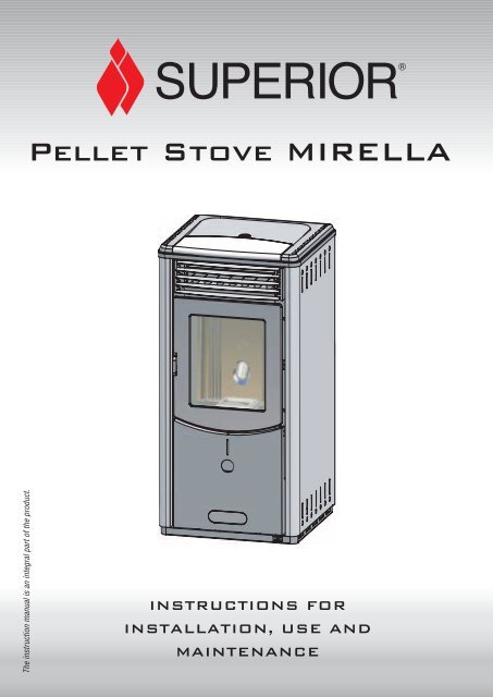
SUPERIOR®<br />
Pellet Stove MIR<st<strong>ro</strong>ng>EL</st<strong>ro</strong>ng>LA<br />
INSTRUCTIONS FOR<br />
INSTALLATION, USE AND<br />
MAINTENANCE
English<br />
Dear client,<br />
We thank you for choosing one of our p<strong>ro</strong>ducts, the result of technological expertise and continued research in pursuit of a superior p<strong>ro</strong>duct<br />
in terms of safety, reliability and features.<br />
In this manual you will find all the information and useful advice necessary to get the most out of your appliance in total safety.<br />
2<br />
DT2010001-00<br />
IMPORTANT INFORMATION DT2010208-02<br />
• This manual has been prepared by the manufacturer and constitutes an integral part<br />
of the p<strong>ro</strong>duct, and must accompany it th<strong>ro</strong>ughout its life. In the event of sale or relocation<br />
of the p<strong>ro</strong>duct make sure this booklet accompanies it, since the information<br />
contained in it is addressed to the purchaser and to anyone involved in the installation,<br />
use and maintenance of the p<strong>ro</strong>duct.<br />
• Read the instructions and the technical information contained in this manual carefully,<br />
before p<strong>ro</strong>ceeding with installation, use or any repairs.<br />
• The observance of the instructions and technical information in this manual guarantees<br />
the safety of the user and the p<strong>ro</strong>duct, a more efficient operation and an<br />
increased lifespan.<br />
• The p<strong>ro</strong>duct’s installation and use should conform to the manufacturer’s instructions<br />
and to local bylaws.<br />
• However, when carrying out any operation we recommend that you follow carefully<br />
the instructions contained in this manual, and that you keep it at your disposal.<br />
• Installation, electrical connection, checks, maintenance and repairs are operations<br />
which must be carried out exclusively by qualified and authorised personal with specialised<br />
knowledge of the p<strong>ro</strong>duct.<br />
• Before installing the p<strong>ro</strong>duct read all instruction booklets relating to installation of the<br />
cladding, the ventilation kit and any other accessories.<br />
• Be very careful when moving any ceramic components.<br />
• Check that the floor where the p<strong>ro</strong>duct is to be installed is exactly level.<br />
• To help correct potential unevenness and irregularities a sheet of adhesive fibreglass<br />
accompanies the p<strong>ro</strong>duct.<br />
• Do not block the electrical socket; it should be close to the unit but accessible.<br />
• Connect the pellet stove to the electricity supply only after it has been connected by<br />
an expert to the flue system.<br />
• The plug at the end of the power supply cable must be easily accessible after installation.<br />
• Use only regulation wood pellets (refer to section entitled “Technical charateristics<br />
and specifications” ).<br />
• Never use liquid fuels to light the stove or to relight the embers.<br />
• Ensure that the area where the stove is installed is p<strong>ro</strong>perly ventilated while the stove<br />
is lit.<br />
• In the event of technical faults the fuel supply will be interrupted. Restart the stove<br />
only after having eliminated the cause of the fault.<br />
• The wall where the p<strong>ro</strong>duct is to be placed should not be of wood or any other flammable<br />
material; furthermore it is important to maintain safety distances (refer to section<br />
entitled ‘Prevention of domestic fires’ contained in the stove’s manual for use<br />
and maintenance).<br />
• Do not remove the p<strong>ro</strong>tective grille f<strong>ro</strong>m the fuel storage tank.<br />
• Any build-up of unused pellets in the burner left over f<strong>ro</strong>m repeated failed ignitions<br />
must be removed before lighting the stove.<br />
• The operation of the stove can cause surfaces, handles, flue system and glass to<br />
become extremely hot.Touch these parts during operation only with p<strong>ro</strong>tective clothing<br />
or other specialised equipment.<br />
• Because of the build-up of heat on the glass, take care that those who are unaware<br />
of the workings of the stove do not delay in the installation area.<br />
• Keep children informed of safety measures to be followed when the stove is operational<br />
and at other times.<br />
In the event of difficulties or if you are unable to understand the instruction<br />
manual contact your local Piazzetta dealer.<br />
It is forbidden to place objects which are not heat-resistant on top of the<br />
stove or within the prescribed minimum safety zone.<br />
It is forbidden to open the door while the stove is in operation or to operate<br />
the stove when the glass is b<strong>ro</strong>ken.<br />
The assembly of the cover should be undertaken by two people (follow the assembly instructions in the attached booklet).<br />
Plans and diagrams are supplied as examples at the manufacturer’s discretion; in the pursuit of a policy of continuous development and innovation<br />
the manufacturer may, without prior warning, make any modifications deemed app<strong>ro</strong>priate.<br />
This document is the p<strong>ro</strong>perty of Gruppo Piazzetta S.p.A.; it may not be divulged in part or in whole to third parties without written permission f<strong>ro</strong>m<br />
Gruppo Piazzetta S.p.A. Gruppo Piazzetta S.p.A. reserves all its statutory rights.<br />
REFERENCE STANDARDS DT2010209-00<br />
DIN 18894 Solid fuel stoves and fireplaces - Pellet-fired stoves - Requirements, testing and marking<br />
UNI 10344 Heating of buildings. Calculation of energy requirements<br />
UNI 10683 Wood-fired heat generators, Installation requirements<br />
UNI 10847 Single flue systems for liquid and solid fuel generators - Maintenance and cont<strong>ro</strong>l - Guidelines and<br />
p<strong>ro</strong>cedures<br />
UNI 7129 Gas installations for domestic use fired by mains gas supply<br />
DIN 51731 class HP2 Fuels<br />
®<br />
SUPERIOR
DT2010187-00<br />
Section Title Page Code<br />
1.0 General rules 4 DT2010216-02<br />
1.1 Single flueway or chimney 5 DT2010024-00<br />
1.2 Soot inspection 5 DT2010031-00<br />
1.3 Chimney stack 6 DT2010025-00<br />
1.4 Fresh air intake 7 DT2010026-00<br />
1.5 Installation envi<strong>ro</strong>nment 7 DT2010215-00<br />
1.6 Capacity load of the floor 8 DT2010032-00<br />
1.7 Heating capacità 8 DT2010130-00<br />
1.8 Minimum safety distances 9 DT2010224-02<br />
1.9 Flue system 9 DT2010229-01<br />
1.10 Connecting to a conventional chimney 11 DT2010230-00<br />
1.11 Using external flue ducts 12 DT2010232-00<br />
1.12 Prevention of domestic fires 12 DT2010027-00<br />
2.0 Technical characteristics and specifications 13 DT2010102-01<br />
2.1 Technical data 13 DT2010103-01<br />
2.2 Plan 13 DT2030134-00<br />
2.3 P<strong>ro</strong>duct identification data 14 DT2010041-00<br />
2.4 Electrical diagram 14 DT2030072-00<br />
3.0 Fuel 15 DT2010233-00<br />
4.0 Before unpacking your p<strong>ro</strong>duct 15 DT2010074-00<br />
5.0 Installation 16 DT2010075-00<br />
5.1 Electrical connection and the temperature sensor 16 DT2010078-00<br />
5.2 Installing the external thermostat 17 DT2010079-00<br />
6.0 Use 17 DT2010080-01<br />
6.1 Cont<strong>ro</strong>l panel 18 DT2010081-00<br />
6.2 Startup 18 DT2010082-00<br />
6.3 Startup and normal operation 19 DT2010083-01<br />
6.4 Remote cont<strong>ro</strong>l 23 DT2010084-00<br />
6.5 Timer 23 DT2010085-00<br />
6.6 Safety features 29 DT2010086-00<br />
6.7 Opening the door 32 DT2010087-01<br />
6.8 Removing the ash 32 DT2010049-00<br />
7.0 Maintenance 33 DT2010111-01<br />
7.1 Cleaning the burner and the burner support 33 DT2010089-01<br />
7.2 Cleaning the ash drawer 33 DT2010100-00<br />
7.3 Cleaning the combustion chamber 33 DT2010090-00<br />
7.4 Cleaning the smoke chamber 34 DT2010091-00<br />
7.5 Cleaning the exhaust system 34 DT2010092-00<br />
7.6 Cleaning the ceramic cover 34 DT2010059-00<br />
7.7 Cleaning the metal parts 34 DT2010061-00<br />
7.8 Cleaning the window 34 DT2010062-00<br />
7.9 Replacing the window 35 DT2010093-00<br />
7.10 Replacing the remote cont<strong>ro</strong>l battery 35 DT2010094-00<br />
7.11 Cleaning the fans 35 DT2010095-00<br />
7.12 When not in use 35 DT2010096-00<br />
7.13 Extraordinary maintenance 35 DT2010097-00<br />
8.0 T<strong>ro</strong>ubleshooting 36 DT2010098-01<br />
Declaration of conformity 39 DT2010101-00<br />
This booklet code H07010500 / DT2000009 - Rev. 02 (04/2005) comprises 40 pages.<br />
®<br />
SUPERIOR<br />
INDEX<br />
3<br />
English
English<br />
4<br />
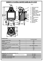
1.0 GENERAL RULES DT2010216-02<br />
Ensure that the installation of your p<strong>ro</strong>duct conforms to all the following instructions.<br />
Fig. 1<br />
CHIMNEY COMIGNOLO STACK<br />
SINGLE FLUEWAY CANNA<br />
OR CHIMNEY FUMARIA<br />
COLLEGAMENTO<br />
FLUE ALLA SYSTEM CANNA FUMARIA<br />
ISPEZIONE PER<br />
SOOT RACCOLTA INSPECTION FULIGGINE<br />
PRESA FRESH AIR D'ARIA INTAKEESTERNA<br />
END <st<strong>ro</strong>ng>EL</st<strong>ro</strong>ng>BOW WITH<br />
INSPECTION RACCORDO WINDOW<br />
CON ISPEZIONE<br />
MINIMUM DISTANZE SAFETY DI SICUREZZA<br />
DISTANCES<br />
CAPACITY VERIFICALOAD<br />
OF PORTATA THE FLOOR SOLAIO<br />
DT2030321-00<br />
®<br />
SUPERIOR
1.1 Single flueway or chimney - Fig. 2÷6<br />
Every appliance must have a vertical flue pipe operating by natural<br />
draught to discharge the combustion gases outdoors.<br />
The flue must:<br />
- comply with regulations in force in the place of installation of the<br />
appliance;<br />
- be tight to the p<strong>ro</strong>ducts of combustion, waterp<strong>ro</strong>of, suitably insulated,<br />
made with materials resistant to the cor<strong>ro</strong>sion of the gases and to<br />
stress;<br />
- be connected to just one stove, fireplace or extraction hood;<br />
- be p<strong>ro</strong>perly sized, with constant free internal section, equal to or<br />
greater than the diameter of the flue pipe of the stove and at least 3.5<br />
m in length;<br />
- be mainly in a vertical position with a deflection f<strong>ro</strong>m the axis of no<br />
more than 45° (Fig. 2);<br />
- be at a suitable distance f<strong>ro</strong>m combustible or flammable materials,<br />
ensured by an air gap or suitable insulating material;<br />
- be of uniform internal section, preferably <strong>ro</strong>und. Square or rectangular<br />
sections must have <strong>ro</strong>unded corners with a radius of at least<br />
20mm and a maximum ratio between the sides of 1.5 (Fig. 4). The<br />
walls must be smooth if possible and without nar<strong>ro</strong>wing. Bends must<br />
be regular and without discontinuity (Fig. 3 - 4 - 5).<br />
It is forbidden to make fixed or mobile apertures on the flue<br />
pipe to connect appliances other than the one to which it is<br />
already connected.<br />
It is forbidden to pass other air ducts or service pipes inside<br />
the flue pipe, however large it is.<br />
If the flue pipe is an incorrect size or installed other than in<br />
compliance with the above instructions, Gruppo Piazzetta<br />
S.p.A. cannot be held liable for malfunctioning of the p<strong>ro</strong>duct,<br />
damage to p<strong>ro</strong>perty or injury to persons or animals.<br />
1.2 Soot inspection - Fig. 1<br />
- The flue must have a chamber for collecting solid matter and any<br />
condensate located below the connection and which may be easily<br />
inspected by means of an airtight door. (Fig.1)<br />
- The bends connecting to the flue must have inspection points that<br />
allow the system to be checked, cleaned and maintained.<br />
®<br />
SUPERIOR<br />
Fig. 2<br />
3.5 Minimo M MINIMUM 3,5 m<br />
Fig. 3<br />
Fig. 5<br />
Deposit of Creosoto<br />
Ø<br />
Accumulo di Creosoto<br />
R (min. 20)<br />
L ( 1,5 x P)<br />
MAX 45°<br />
DT2030050-00<br />
P<br />
DT2030189-00<br />
Fig. 4<br />
Fig. 6<br />
NO<br />
X<br />
NO<br />
R (min. 20)<br />
Accumulo di Creosoto<br />
Deposit of Creosoto<br />
DT2030049-00<br />
DT2030188-00<br />
DT2030190-00<br />
5<br />
English
English<br />
1.3 Chimney stack - Fig. 7 ÷ 11<br />
The flue must be fitted at the top with a device called a chimney stack,<br />
designed to aid dispersion of the p<strong>ro</strong>ducts of combustion in the atmosphere.<br />
The chimney stack must comply with the following requirements:<br />
- it must have an internal section and shape the same as the flue;<br />
- it must have a useful outlet section of not less than twice that of the flue;<br />
- the part of the flue that emerges f<strong>ro</strong>m the <strong>ro</strong>of or remains in contact with the<br />
outside (e.g. in the case of an open loft), must be covered with brick or tile elements<br />
and in any case well insulated. It must be built in such a way as to prevent<br />
the penetration of rain, snow and foreign matter into the flue and to ensure<br />
that in the event of winds f<strong>ro</strong>m all directions and angle, discharge of the<br />
combustion p<strong>ro</strong>ducts is assured (chimney stack with down-draught cowl);<br />
- any buildings or other obstacles that are higher than the chimney stack must<br />
not be too close to the actual stack Fig.8 - Fig.9;<br />
- the chimney stack must be positioned in such a way as to ensure adequate<br />
dispersion and dilution of the p<strong>ro</strong>ducts of combustion and in any case outside<br />
the reflux area.The size and shape of this area differ according to the angle<br />
of inclination of the <strong>ro</strong>of and it is therefore necessary to adopt the minimum<br />
heights shown in Fig.10;<br />
Example: Check the slope of the <strong>ro</strong>of (column α), and the anticipated<br />
distance of the chimney stack f<strong>ro</strong>m the axis of the ridge (column A), if<br />
the distance is greater than “A” lthe height of the chimney stack may<br />
be read in (column H); if the distance is less than “A” the chimney stack<br />
must rise above the ridge by 0.5 metres.<br />
Fig. 10<br />
Fig. 11<br />
6<br />
Pitch of the <strong>ro</strong>of<br />
H min.<br />
H min.<br />
pari 5 o minore m<br />
pari or 5o less mminore<br />
5 m<br />
0.50 m<br />
0.50 m<br />
distanza maggiore A<br />
distanza distance maggiore more distanza than AA<br />
min. distanza distance uguale A<br />
min. at least uguale A<br />
α<br />
Horizontal width of reflux<br />
area f<strong>ro</strong>m ridge axis<br />
Fig. 9<br />
asse colmo<br />
asse ridge colmo axis<br />
maggiore over 5 m5<br />
m<br />
maggiore 5 m<br />
0.50 m oltre il colmo<br />
0.50 above m oltre the il colmo ridge<br />
6-8 m<br />
TETTO PIANO<br />
TETTO PIANO<br />
pari 5 o minore m<br />
pari or 5o less mminore<br />
5 m<br />
Minimum height of<br />
outlet f<strong>ro</strong>m <strong>ro</strong>of<br />
0.50 m<br />
0.50 m<br />
TETTO INCLINATO<br />
TETTO INCLINATO<br />
altezza zona di<br />
reflusso height altezza of zona Z di<br />
reflux reflusso area Z Z<br />
Height of reflux<br />
area<br />
α A H minimo Z<br />
15° 1.85 m 1.00 m 0.50 m<br />
30° 1.50 m 1.30 m 0.80 m<br />
45° 1.30 m 2.00 m 1.50 m<br />
60° 1.20 m 2.60 m 2.10 m<br />
Fig. 7<br />
A<br />
B*<br />
* B equivale it is twiceal<br />
doppio of to Adi<br />
A<br />
DT2030051-00<br />
FLAT ROOF<br />
Fig. 8<br />
SLOPING ROOF<br />
B<br />
A<br />
B<br />
DT2030191-00<br />
DT2030052-00<br />
DT2030053-00<br />
DT2030192-00<br />
®<br />
SUPERIOR
1.4 Fresh air intake - Fig. 12÷15<br />
The stove/fireplace must have the necessary air available to ensure<br />
p<strong>ro</strong>per combustion.<br />
- Make sure that the <strong>ro</strong>om in which the stove/fireplace is to be installed<br />
has an air intake of at least the size indicated in the paragraph<br />
“TECHNICAL DATA”.<br />
- The fresh air intake may be p<strong>ro</strong>tected by an external grille p<strong>ro</strong>vided it<br />
does not reduce the minimum section of the recommended airflow<br />
and is in a position whereby it cannot be obstructed.<br />
The air necessary for the fire may be obtained in different ways:<br />
- Figure 12 th<strong>ro</strong>ugh an external grille direct to the <strong>ro</strong>om of installation;<br />
- Figure 13 with ducting th<strong>ro</strong>ugh pipes direct to the <strong>ro</strong>om of installation,<br />
increasing the recommended minimum free c<strong>ro</strong>ss section by at<br />
least 15%;<br />
- Figure 14 th<strong>ro</strong>ugh a communicating hole f<strong>ro</strong>m an adjacent <strong>ro</strong>om to<br />
the place of installation: this system may only be used if the air flows<br />
freely f<strong>ro</strong>m the outside th<strong>ro</strong>ugh fixed apertures;<br />
- Figure 15 f<strong>ro</strong>m an adjacent <strong>ro</strong>om to the place of installation, but only<br />
if the air flows freely th<strong>ro</strong>ugh apertures communicating with the outside.<br />
1.5 Installation envi<strong>ro</strong>nment<br />
The appliance should be installed in a location which allows safe and<br />
convenient use as well as easy maintenance. If the p<strong>ro</strong>duct being<br />
installed requires an electrical socket, the <strong>ro</strong>om must also be p<strong>ro</strong>vided<br />
with an earthed power supply in accordance with current regulations.<br />
The installation of a wood-burning appliance in a bed<strong>ro</strong>om,<br />
bath or shower <strong>ro</strong>om or in any <strong>ro</strong>om where another heating<br />
system not equipped with its own air supply (fireplace, stove<br />
etc.) has already been installed is forbidden.<br />
The <strong>ro</strong>om or <strong>ro</strong>oms adjacent to that where the appliance is to be installed<br />
must conform to the following requirements:<br />
It must not be used as a car bay, a store for combustible material,<br />
nor for any activity which carries a risk of fire.<br />
It must not be pressurised relative to normal atmospheric pressure<br />
as a result of the draught created by a prior installation of<br />
an open fire or of an extractor system.<br />
In the same location do not install two stoves, a stove and a fireplace,<br />
a stove and a wood-burning range etc, since the draught<br />
f<strong>ro</strong>m one device can interfere with the draught f<strong>ro</strong>m another.<br />
- The use of equipment adapted for cooking food with non-extractor<br />
hoods is permissible only in <strong>ro</strong>oms to be used as kitchens.<br />
- Equipment using gas type C is permitted (refer to regulations in force<br />
in the place of installation).<br />
®<br />
SUPERIOR<br />
Fig. 12<br />
Fig. 14<br />
Fig. 15<br />
DT2030054-00<br />
Fig. 13<br />
DT2030193-00<br />
DT2030194-00<br />
DT2030195-00<br />
7<br />
English
English<br />
8<br />
Equipment using gas type B is not permitted (refer to regulations<br />
in force in the place of installation).<br />
Using the stove or flue simultaneously with shared ventilation<br />
systems is not permitted, whether with or without extractor<br />
fans. Similarly the use of other devices or equipment, such as<br />
air-conditioning systems or other heating systems which use<br />
fans to circulate air, is not permitted. These devices can cause<br />
the atmosphere a<strong>ro</strong>und the stove to become pressurised even<br />
if installed in adjacent, communicating <strong>ro</strong>oms.<br />
1.6 Capacity load of the floor<br />
Check the load-bearing capacity of the floor, referring to the weight of the<br />
p<strong>ro</strong>duct given in the paragraph “TECHNICAL DATA”.<br />
If the floor does not have a suitable load-bearing capacity, adequate countermeasures<br />
must be taken, for example, by using a sheet metal plate to<br />
distribute the load.<br />
1.7 Heating capacity<br />
Check the heating capacity of the appliance by comparing the rated power<br />
given in the paragraph “TECHNICAL DATA” with the power required by the<br />
envi<strong>ro</strong>nment to be heated.<br />
The energy requirement may be calculated app<strong>ro</strong>ximately by multiplying<br />
the square metres of area by the height of the ceiling; the result is then<br />
multiplied by a coefficient, which depends on the degree of insulation of<br />
the building, that is, on internal and external factors of the dwelling:<br />
a) Internal factors: type of window and door frames, thickness of the<br />
insulation and walls, type of building materials, presence of stairwells,<br />
walls with extensive glazing, high ceilings, position of the <strong>ro</strong>oms to be<br />
heated in relation to other adjacent heated or unheated <strong>ro</strong>oms, …<br />
b) External factors: geographical position, average outdoor temperature,<br />
exposure, wind speed, latitude, altitude, …<br />
Example of app<strong>ro</strong>ximate calculation of the energy requirement to<br />
heat a fixed volume to 18/20° C:<br />
The coefficient that is normally used is determined according to the real<br />
conditions as they occur case by case.<br />
- F<strong>ro</strong>m 0.04 to 0.05 kW per cubic metre in a well insulated envi<strong>ro</strong>nment<br />
- F<strong>ro</strong>m 0.05 to 0.06 kW per cubic metre in a poorly insulated envi<strong>ro</strong>nment.<br />
3 <strong>ro</strong>oms measuring 20m2 X (H ceiling) 2.7m = 162 m3 (volume)<br />
In an envi<strong>ro</strong>nment with a good degree of insulation, an average value<br />
(coefficient) of 0.045 kW may be taken<br />
162 (volume) X 0.045 (kW) = 7.3 kW necessary (6300 kcal/h)<br />
Conversion 1kW = 860 kcal/h<br />
Consult a heating technician or engineer for a correct check<br />
and calculation of the requirement of the envi<strong>ro</strong>nments to be<br />
heated (see “REFERENCE STANDARDS”).<br />
Rated power being equal, p<strong>ro</strong>ducts with the Multi-fire system<br />
can evenly distribute heat th<strong>ro</strong>ughout the <strong>ro</strong>oms to be heated.<br />
®<br />
SUPERIOR
1.8 Minimum safety distances - Fig. 16÷18<br />
With reference to the above diagram, the minimum safe distances f<strong>ro</strong>m<br />
heat sensitive or inflammable materials, such as load bearing and other<br />
walls are:<br />
A 20 cm f<strong>ro</strong>m the wall behind the stove<br />
B 60 cm f<strong>ro</strong>m the side wall<br />
C 100 cm in the radiating area<br />
In the case of flooring that is heat sensitive or inflammable the floor<br />
should be p<strong>ro</strong>tected (using for example sheets of steel plate, marble or<br />
tiles).<br />
The minimum distances are:<br />
D 50 cm;<br />
E 30 cm (measured f<strong>ro</strong>m the internal corner of the door opening).<br />
Keep any combustible p<strong>ro</strong>duct well away f<strong>ro</strong>m the stove when it<br />
is lit (minimum distance f<strong>ro</strong>m the heat radiation area), for example:<br />
wooden furniture, curtains, carpets, combustible liquids, etc.<br />
1.9 Flue system - Fig. 19-20<br />
The pellet stove is not the same as other stoves. The smoke is<br />
p<strong>ro</strong>pelled by a fan which keeps the combustion chamber pressurised<br />
and the entire flue system slightly pressurised. For this<br />
reason the flue must be completely airtight and correctly installed<br />
to ensure both t<strong>ro</strong>uble-free operation and user safety.<br />
- The construction of the exhaust system must be undertaken by specialised<br />
personnel or firms, as outlined in the following pages.<br />
- Installation of the flue should be completed in such a way as to guarantee<br />
that periodic cleaning can be carried out without dismantling<br />
the entire system.<br />
- Pipes should always be sealed with silicone (not cement-based<br />
sealants) or specially adapted washers which will retain their elastic<br />
and resistant p<strong>ro</strong>perties at high temepratures (250°C). These should<br />
be attached with 3.9mm-diameter self-threading screws.<br />
The installation of flaps or valves which might block the passage<br />
of the smoke is not permitted.<br />
The installation of other devices (boilers, extractor hoods etc)<br />
which might release fumes or vapours into the flue system is<br />
not permitted.<br />
®<br />
SUPERIOR<br />
Fig. 16<br />
Fig. 17<br />
Parete Side wall laterale<br />
Parete Rear posteriore wall<br />
A<br />
B STUFA STOVE<br />
B<br />
E<br />
P<strong>ro</strong>tezione Floor p<strong>ro</strong>tection a pavimento<br />
D<br />
Radiating zone<br />
Zona radiante dell'apertura del focolare<br />
MIN 40 cm<br />
DT2030335-00<br />
Fig. 18<br />
C<br />
E<br />
Parete Side wall laterale<br />
DT2030059-01<br />
MIN 40 cm<br />
DT2030336-00<br />
9<br />
English
English<br />
Pipes and maximum usable lengths<br />
Pipes of aluminium-clad painted steel (minimum thickness<br />
1.5mm), stainless steel (Aisi 316) or enamelled steel (minimum<br />
thickness 0.5mm) with a nominal diameter of 80 or 100mm (for<br />
pipes which run inside the flue maximum diameter 150mm) can be<br />
used.<br />
The male-female connectors must have a minimum length of<br />
50mm.<br />
The diameter of the pipes used depends on the type of installation.<br />
The stove was designed to take 80mm-diameter pipes but, as<br />
shown in Table 1, in some cases the use of double-lined 100mmdiameter<br />
pipes is recommended.<br />
TYPE OF INSTALLATION<br />
TABLE 1 LENGHT PIPES<br />
WITH 80mm Ø PIPE<br />
WITH DOUBLE-WAL-<br />
LED 100mm Ø PIPE<br />
Maximum length (with three 90° bends) 4.5 m 8 m<br />
For installations more than 1200m above sea level - Required<br />
Maximum number of bends 3 4<br />
Length of horizontal sections with minimum 5% gradient 2 m 2 m<br />
10<br />
Losses associated with a 90° bend can be compared to those<br />
incurred by one metre of pipe. An inspectable T-connector<br />
can be considered equivalent to a 90° bend.<br />
EXAMPLE: If installing a section greater than 4.5m in length with<br />
80mm-diameter pipe, calculate the maximum usable length in the following<br />
ways:<br />
- If in the section to be fitted a maximum of three 90° bends are used,<br />
the maximum length of the section will be 4.5m.<br />
- If in the section to be fitted a maximum of two 90° bends are used<br />
and bearing in mind that a 90° bend can be replaced by one meter of<br />
pipe, the maximum length of the section will be 4.5m+1m=5.5m.<br />
- If in the section to be fitted a maximum of one 90° bend is used and<br />
bearing in mind that a 90° bend can be replaced by one meter of<br />
pipe, the maximum length of the section will be<br />
4.5m+1m+1m=6.5m.<br />
Where 100mm-diameter pipe must be used, connect it to the stove’s<br />
exhaust outlet with a 80mm T-connector then use a 80mm-100mm<br />
adaptor (not supplied by Piazzetta) (Fig 19).<br />
T-connector<br />
The use of this type of connector must allow for the collection of condensation<br />
mixed with suit which builds up inside the pipe. It must also<br />
permit the periodic cleaning of the flue without the need to dismantle<br />
the pipes.<br />
This type of connctor can be bought at Piazzetta outlets together with<br />
the pipes.<br />
Outlined below is an example of a set-up which can be cleaned entirely<br />
without the need to dismantle the pipes (Fig 20).<br />
Fig. 19<br />
Fig. 20<br />
Tee RACCORDO A T<br />
Direction DIREZIONE of<br />
cleaning DI PULIZIA<br />
ø 100mm<br />
RACCORDO<br />
ø 80 > ø 100<br />
ø 80mm<br />
RACCORDO A T CON TAPPO<br />
Tee with sealing plug<br />
A CHIUSURA ERMETICA<br />
ISOLANTE Insulating material<br />
Tee RACCORDO A T<br />
Max 2m<br />
(min. 3%)<br />
DIREZIONE Direction of DI cleaning<br />
PULIZIA<br />
Straight reducer<br />
ø 80 > ø 100<br />
DT2030337-00<br />
DIREZIONE Direction of DI cleaning PULIZIA<br />
DT2030338-00<br />
®<br />
SUPERIOR
1.10 Connecting to a conventional chimney - Fig. 21-22<br />
If you wish to use an existing chimney it is st<strong>ro</strong>ngly recommended that<br />
you have it checked by a p<strong>ro</strong>fessional chimney-sweep to ensure that it<br />
is completely airtight. The reason for this is that the smoke, because it<br />
is slightly pressurised, can infiltrate any cracks in the system and escape<br />
into living spaces. If upon inspection you find that the chimney is not<br />
completely sound, it is recommended that you insert piping made of<br />
new material. If the existing chimney is wide enough we recommend a<br />
pipe with a maximum diameter of 150mm. It is also recommended that<br />
you insulate the chimney flue (Fig. 21-22).<br />
For connection to the chimney the use of Piazzetta’s own pipes and<br />
bends is recommended - the stove’s outlet is the right size to connect<br />
to these.<br />
Other types of pipe can be used, p<strong>ro</strong>vided that they are suitable or that<br />
the compatibility of the connecting sleeve can be verified. Bear in mind<br />
also that pipes and bends must be constructed according to existing<br />
regulations. In such cases however Gruppo Piazzetta S.p.A guarantees<br />
the p<strong>ro</strong>per functioning of the stove only where its own equipment has<br />
been employed in accordance with its own instructions.<br />
The connection to the flue system must respect the 40cm minimum<br />
safety distance f<strong>ro</strong>m objects which are sensitive to heat and f<strong>ro</strong>m<br />
inflammable materials (wooden veneers, beams or ceilings etc). (See<br />
figures 17-18)<br />
- If the connector has to pass th<strong>ro</strong>ugh partitions or walls constructed<br />
f<strong>ro</strong>m inflammable or heat-sensitive materials, or th<strong>ro</strong>ugh weight-bearing<br />
walls, you must int<strong>ro</strong>duce:<br />
an insulated barrier equal to or greater than 10cm a<strong>ro</strong>und the connector<br />
using a mineral-based insulating material (<strong>ro</strong>ck wool, ceramic<br />
fibre) with a nominal density greater than 80kg/m 3<br />
- If the connector has to pass th<strong>ro</strong>ugh partitions or walls constructed<br />
f<strong>ro</strong>m heat-resistant materials, you must int<strong>ro</strong>duce:<br />
an insulated barrier equal to or greater than 5cm a<strong>ro</strong>und the connector<br />
using a mineral-based insulating material (<strong>ro</strong>ck wool, ceramic<br />
fibre) with a nominal density greater than 80kg/m 3.<br />
- Check that the connection to the flue system has been carried out so<br />
as to guarantee that smoke will not leak f<strong>ro</strong>m it under the equipment’s<br />
pressurised operating conditions.<br />
- Check that the pipe does enter too far into the flue creating a nar<strong>ro</strong>wing<br />
of the exhaust passage. Figure 22-23<br />
Ensure that all installation work is carried out to p<strong>ro</strong>fessional<br />
standards.<br />
®<br />
SUPERIOR<br />
Fig. 21<br />
Tee RACCORDO A T<br />
Fig. 22<br />
INSERIMENTO DI<br />
Pipe<br />
UN TUBO<br />
insertion<br />
Closing FLANGIA flange DI CHIUSURA<br />
ø 80 mm<br />
Sealing FLANGIA flange DI CHIUSURA in stainless ERMETICA<br />
steel IN ACCIAIO or aluminium INOX O ALLUMINATO<br />
Chimney COMIGNOLO stack<br />
Fresh air PRESA intake D'ARIA with ESTERNA<br />
non-closable CON GRIGLIA NON grilleRICHIUDIBILE<br />
With CON CANNA damaged FUMARIA flue<br />
NON INTEGRA<br />
Max ø150 mm<br />
Inspection SPORT<st<strong>ro</strong>ng>EL</st<strong>ro</strong>ng>LI PER<br />
windows ISPEZIONE<br />
Insulating ISOLANTE material<br />
DT2030339-00<br />
DT2030340-00<br />
11<br />
English
English<br />
1.11 Using external flue ducts<br />
You can use external flue ducts only when they correspond to the following<br />
requirements:<br />
- Use only insulated pipes (double-lined) in stainless steel attached to<br />
the outside wall (Fig 23).<br />
- At the base of the duct there must be an inspection hatch to permit<br />
periodic checks and maintenance.<br />
- The installation must be equipped with an windp<strong>ro</strong>of chimney and<br />
respect the safety distance f<strong>ro</strong>m the high point of the <strong>ro</strong>of as outlined<br />
in the chapter entitled “GENERAL RULES”, under “Chimney top”.<br />
12<br />
Ensure that all installation work is carried out to p<strong>ro</strong>fessional<br />
standards.<br />
1.12 Prevention of domestic fires<br />
The p<strong>ro</strong>duct must be installed and used in compliance with the manufacturer’s<br />
instructions and Eu<strong>ro</strong>pean and national standards as well as<br />
local regulations.<br />
When a flue pipe passes th<strong>ro</strong>ugh a wall or a ceiling, special<br />
installation methods must be applied (p<strong>ro</strong>tection, thermal<br />
insulation, distances f<strong>ro</strong>m heat-sensitive materials, etc.) See<br />
the paragraph “Connection to the flueway”.<br />
- It is also recommended that all elements made of combustible or<br />
inflammable material, such as beams, wooden furniture, curtaining,<br />
flammable liquids, etc. be kept outside the heat radiation range of the<br />
stove and in any case at a distance of at least 1m f<strong>ro</strong>m the heating<br />
block.<br />
- For other information, see the paragraph “Safety distances” and<br />
“Connection to the flueway”.<br />
- The flue pipe, chimney stack, chimney and fresh air intake must<br />
always be free of obstructions, clean and checked periodically, that is,<br />
at least twice during the seasonal period f<strong>ro</strong>m the lighting of the stove<br />
and during its use. When the stove has not been used for some time<br />
it is advisable to carry out the checks mentioned above. For further<br />
information, consult a chimneysweep.<br />
- Only use recommended fuels (See paragraph “Fuels”).<br />
Fig. 23<br />
d<br />
PRESA Fresh D'ARIA air intake ESTERNA withCON<br />
GRIGLIA non-closable NON RICHIUDIBILE grille<br />
DT2030341-00<br />
®<br />
SUPERIOR
DT2010102-01<br />
2.1 Technical data<br />
• Fuel: Natural wood pellets • Length: < 30mm<br />
• Diameter: ca. 6 - 6.5 mm<br />
• Water content: ca. 6% - 8%.<br />
Data obtained under laboratory conditions with pellets of heat p<strong>ro</strong>duction rated at 5kwh/kg.<br />
2.2 Plan (cm)<br />
®<br />
SUPERIOR<br />
2.0 TECHNICAL CHARACTERISTICS AND SPECIFICATIONS<br />
UNIT MIR<st<strong>ro</strong>ng>EL</st<strong>ro</strong>ng>LA<br />
Hourly fuel consumption (max/min) kg/h 1,4 / 0,75<br />
Nominal thermal power (max/min) kW 5,5 / 2,5<br />
Efficiency % > 80<br />
Draught when connected to chimney Pa 10÷15<br />
Fuel tank capacity kg / (l) 15 / (23)<br />
Electrical power supply V 230<br />
Frequenz Hz 50<br />
Maximum power rating W 320<br />
Power rating (max / min) W 110 / 70<br />
Exhaust outlet diameter cm Ø 8<br />
Fresh air intake with minimum useful section cm 2 100<br />
Weight with majolica kg 85<br />
Packing cladding kg 95<br />
Packing sizes (DxWxH) cm 58,5X54X119<br />
Diameter Ø 8<br />
15 7<br />
17,5<br />
94<br />
43<br />
46<br />
DT2030071-00<br />
13<br />
English
English<br />
2.3 P<strong>ro</strong>duct identification data<br />
The rating plate gives the data and ratings of the appliance.<br />
If the rating plate is missing, has been removed or tampered with,<br />
any installation and maintenance operations are made difficult due<br />
to lack of p<strong>ro</strong>duct identification.<br />
In the event of damage, please ask the Piazzetta after-sales service<br />
centre for a copy.<br />
2.4 Electrical diagram<br />
14<br />
Flat cable<br />
DB 9<br />
LN<br />
ROOM SENSOR<br />
CN2<br />
IC10<br />
SERIAL<br />
FAN 1<br />
FAN 2<br />
EXTERNAL<br />
THERMOSTAT<br />
F<br />
N<br />
SMOKE<br />
SMOKE<br />
POINTS<br />
POINTS<br />
FU<st<strong>ro</strong>ng>EL</st<strong>ro</strong>ng>-LOADING CHUTE<br />
FU<st<strong>ro</strong>ng>EL</st<strong>ro</strong>ng>-LOADING CHUTE<br />
PILOT LIGHT<br />
PILOT LIGHT<br />
AL . 2<br />
AL . 1<br />
N<br />
Black<br />
Black<br />
Blue<br />
Red<br />
THERMO<st<strong>ro</strong>ng>EL</st<strong>ro</strong>ng>EMENT ABGASE<br />
Display<br />
1<br />
2<br />
3<br />
4<br />
5<br />
6<br />
7<br />
8<br />
9<br />
10<br />
11<br />
12<br />
Light blue<br />
B<strong>ro</strong>wn<br />
Light blue<br />
B<strong>ro</strong>wn<br />
White<br />
White<br />
Yellow-green<br />
Yellow-green<br />
White<br />
Grau<br />
Red<br />
Red<br />
Black<br />
Light blue<br />
Yellow-green<br />
Smoke fan<br />
Blue<br />
Black<br />
B<strong>ro</strong>wn<br />
Black<br />
Fuel-loading chute<br />
Capacitor<br />
N.A. PRESSURE SWITCH<br />
2<br />
80 1 2<br />
N. C.<br />
P<br />
Weiß<br />
2 1 THERMOSTATS<br />
N. C. 180<br />
P<br />
G<br />
N<br />
L<br />
POWER<br />
3<br />
Black<br />
P<strong>ro</strong>duct name<br />
Serial number<br />
Room fan<br />
PILOT LIGHT<br />
SMOKE SENSOR<br />
DT2030624-00<br />
DT2030072-00<br />
®<br />
SUPERIOR
DT2010233-00<br />
The pellet stove has been designed to burn only wood in pellet form.<br />
The wood pellet is obtained by pressing wood sawdust left over f<strong>ro</strong>m the<br />
working of natural dried wood. The typical small, cylindrical form is obtained<br />
by a p<strong>ro</strong>cess similar to wire-drawing. Thanks to lignin, a natural element<br />
which is released during the pressing of the raw material, the pellets acquire<br />
a good consistency and compactness without requiring treatment with additives<br />
or caking agents.<br />
There are various types of pellet on the market with qualities and characteristics<br />
which vary depending on the p<strong>ro</strong>cesses they have undergone<br />
and the type of wood used in their p<strong>ro</strong>duction.<br />
Since the pellet’s characteristics and quality affect to a considerably<br />
degree the stove’s performance, p<strong>ro</strong>ductivity and p<strong>ro</strong>per<br />
functioning we recommend that you USE high-quality pellets.<br />
Gruppo Piazzetta S.p.A has tested and p<strong>ro</strong>grammed its stoves and<br />
can p<strong>ro</strong>mise optimum performance and t<strong>ro</strong>uble-free functioning<br />
using pellets with these specific characteristics:<br />
• Material: wood<br />
• Length: not greater than 30mm<br />
• Diameter: 6-6.5mm<br />
• Inferior heat energy: 5kWh/kg<br />
• Humidity: not greater than 8%<br />
• Residual ash: 0.34%<br />
To assure t<strong>ro</strong>uble-free operation:<br />
DO NOT use pellets with dimensions different to those stipulated by the<br />
manufacturer.<br />
DO NOT use pellets which are out of date or which contain loose sawdust,<br />
resins, chemical substances, additives or caking agents.<br />
DO NOT use damp pellets.<br />
DT2010074-00<br />
During operation, some parts of the stove (door, handle, display,<br />
ceramic parts) can reach high temperatures. Therefore take due<br />
precautions, above all in the presence of children, elderly and disabled<br />
persons and pets.<br />
In order to avoid accidents or damage to the p<strong>ro</strong>duct, the following<br />
recommendations are made:<br />
• Unpacking and installation must be carried out by at least two<br />
people.<br />
• Every operation involving movement of the p<strong>ro</strong>duct must be carried<br />
out with the p<strong>ro</strong>per tools in full compliance with current safety<br />
regulations.<br />
®<br />
SUPERIOR<br />
Choosing pellets different to those stipulated:<br />
- obstructs the burner and flue ducts<br />
- increases fuel consumption<br />
- reduces efficiency<br />
- cannot guarantee the stove’s p<strong>ro</strong>per functioning<br />
- causes dirt to build up on the glass<br />
- leaves particles which have failed to burn and heavy cinders.<br />
3.0 FU<st<strong>ro</strong>ng>EL</st<strong>ro</strong>ng><br />
The presence of dampness in the pellets increases their volume and<br />
causes them to split which in turn causes:<br />
- malfunction of the fuel-loading system<br />
- inefficient combustion.<br />
Pellets should be stored in a sealed, dry place.<br />
If you wish to use good-quality pellets with different dimensions and heatp<strong>ro</strong>ducing<br />
p<strong>ro</strong>perties to those stipulated you will need to alter the operating<br />
parameters of the stove. This “customisation” of the stove’s settings must<br />
be carried out at one of Gruppo Piazzetta S.p.A.’s Centres for Technical<br />
Assistance or by specially qualified personnel authorised by Gruppo<br />
Piazzetta S.p.A.<br />
Using out of date pellets or those which do not conform to the<br />
manufacturer’s stipulations damages the stove and comp<strong>ro</strong>mises<br />
performance as well as can nullifying the guarantee<br />
and excusing the manufacturer f<strong>ro</strong>m his responsibilities.<br />
DT2030346-00<br />
4.0 BEFORE UNPACKING YOUR PRODUCT<br />
• The orientation of the packaged p<strong>ro</strong>duct must conform to the<br />
directions given in the diagrams and notices on the package.<br />
• If cables, straps or chains are used, ensure that they are able to<br />
take the weight of the package and that they are in good condition.<br />
• While moving the package use slow continuous movements to<br />
avoid tearing cables, chains etc.<br />
• To avoid toppling do not lean the package excessively.<br />
• Do not stop in the path of loading/unloading equipment (cradles,<br />
cranes etc).<br />
15<br />
English
English<br />
16<br />
5.0 INSTALLATION DT2010075-00<br />
External pressure switch<br />
• The stove is equipped with an external socket for measuring the<br />
air pressure in the flue. This verifying and checking operation<br />
should be carried out by authorised personnel whilst the stove is<br />
being installed.<br />
5.1 Electrical connection and the temperature sensor - Fig. 24-25<br />
• The stove comes equipped with a power cable which must be<br />
connected to a 230v/50Hz supply. Connection to the rear of the<br />
stove is illustrated in fig 25.<br />
• The power rating is indicated in the section ‘technical characteristics<br />
and data’ in this manual.<br />
• According to law the installation must be earthed and include a<br />
differential switch.<br />
• Ensure that in its normal position the power cable does not come<br />
into contact with any heated parts.<br />
Ensure that the electrical socket is accessible after the<br />
stove’s installation.<br />
• At the same time as installing the stove, it is necessary to connect<br />
the temperature sensor (p<strong>ro</strong>vided) in the correct socket (fig<br />
25). The sensor can be positioned as illustrated in fig 25, or<br />
uncoil the nar<strong>ro</strong>w strip and place the sensor in a spot where a<br />
more accurate <strong>ro</strong>om temperature reading can be obtained.<br />
Covering<br />
• Having carried out the assembly and the installation of the external<br />
thermostat, p<strong>ro</strong>ceed with the assembly of the stove’s cover.<br />
For this operation refer to the booklet entitled Instructions manual<br />
ceramic cladding p<strong>ro</strong>vided with the stove.<br />
Fig. 24<br />
Fig. 25<br />
1<br />
2<br />
DT2030074-00<br />
1 External socket for connection of temperature sensor.<br />
2 Socket for power lead.<br />
3 External pressure sockets.<br />
4 Socket for inserting cable PG7 for connection of external thermostat.<br />
5 Connecting the temperature sensor.<br />
6 Connecting the power cable.<br />
5<br />
6<br />
3<br />
4<br />
DT2010071-00<br />
DT2030075-00<br />
®<br />
SUPERIOR
5.2 Installing the external thermostat - Fig. 24 - 26 - 27 - 28<br />
• To connect the external thermostat use cable type 2x0.5mm 2<br />
stopped with a PG7 connector to be inserted in the app<strong>ro</strong>priate<br />
socket in the rear panel (fig 24). This operation should be carried<br />
out by authorised personnel.<br />
Installation can be carried out with any type of thermostat<br />
but requires connector PG7 similar to that shown in fig 26.<br />
To connect the thermostat to the elect<strong>ro</strong>nic board, refer to<br />
the electrical diagram.<br />
• To install, stop the thermostat cable with connector PG7 and<br />
insert this in the socket at the rear (fig 25 ÷ 28). Finally connect<br />
the thermostat’s terminal to the two-pin terminal of the elect<strong>ro</strong>nic<br />
board (fig 27).<br />
DT2010080-01<br />
• Do not use the stove as a cooker<br />
• Ensure that the <strong>ro</strong>om in which the stove is installed is sufficiently<br />
well ventilated.<br />
• Ensure that all joints in the flue are hermetically sealed using a<br />
silicone- (not cement-) based sealant which is resistant to temperatures<br />
of up to 250ºC and which shows no sign of deterioration.<br />
• Check (or have checked) regularly that the flue is clean.<br />
• It is p<strong>ro</strong>hibited to use fuels other than pellets.<br />
• Remove any deposits of unused pellets left by failed ignitions<br />
before restarting the stove.<br />
The removal of the p<strong>ro</strong>tective grille inside the fuel tank is<br />
strictly p<strong>ro</strong>hibited.<br />
®<br />
SUPERIOR<br />
Fig. 26<br />
Fig. 27<br />
Fig. 28<br />
1 2<br />
1 Thermostat.<br />
2 Elect<strong>ro</strong>nic board 2-pin terminal.<br />
3 Cable clamp.<br />
4 Thermostat cable terminal.<br />
3<br />
DT2030076-00<br />
DT2030077-00<br />
DT2030078-00<br />
6.0 USE<br />
If replenishing the pellets while the stove is lit, ensure that<br />
the bag does not come into contact with any hot surfaces.<br />
Keep any inflammable object well away f<strong>ro</strong>m the stove<br />
while it is in use (MINIMUM 100 cm f<strong>ro</strong>m the f<strong>ro</strong>nt panel).<br />
While in use the door must remain closed and the glass<br />
must be present and intact.<br />
4<br />
DT2010035-00<br />
17<br />
English
English<br />
6.1 Cont<strong>ro</strong>l 6<br />
4<br />
panel - Fig. 29<br />
4<br />
6<br />
• The stove is equipped with a digital cont<strong>ro</strong>l panel which allows<br />
6<br />
6 the user to cont<strong>ro</strong>l the various functions.<br />
6<br />
6<br />
The cont<strong>ro</strong>l panel keys and their various functions are listed below.<br />
6<br />
These have been numbered in order to make identification easier..<br />
18<br />
1<br />
1<br />
1<br />
1<br />
1<br />
1<br />
1<br />
1<br />
2<br />
2<br />
21<br />
21<br />
2<br />
321<br />
2<br />
321<br />
32<br />
3<br />
32<br />
32<br />
3<br />
2<br />
3<br />
3 2<br />
3<br />
SET<br />
SET<br />
SET<br />
SET<br />
3<br />
OK<br />
3 OK<br />
OK<br />
OK<br />
OK<br />
OK<br />
OK<br />
OK<br />
OK<br />
OK<br />
OK<br />
SET<br />
OK<br />
SET<br />
SET<br />
SET<br />
SET<br />
SET<br />
SET<br />
SET<br />
SET SET<br />
6<br />
45<br />
4<br />
5<br />
4<br />
5<br />
45<br />
5<br />
5<br />
6<br />
65<br />
5<br />
65<br />
6<br />
5<br />
5<br />
4<br />
4<br />
4<br />
4<br />
4<br />
4<br />
5<br />
5<br />
4<br />
SET<br />
SET<br />
SET<br />
SET<br />
SET<br />
SET<br />
SET<br />
ON-OFF key<br />
Power key<br />
Fan and timer cont<strong>ro</strong>l Keys<br />
Function select<br />
AL. C<br />
AL. CC<br />
AL. C<br />
AL. C<br />
AL. C<br />
AL. AL. AL. FC<br />
FCC<br />
AL. F<br />
AL.<br />
FC<br />
AL.<br />
C<br />
AL. FF<br />
AL. FC<br />
AL. FF<br />
AL. F<br />
AL. F<br />
AL. F<br />
GRUPPO AL. PIAZZETTA F<br />
GRUPPO PIAZZETTA Display<br />
GRUPPO PIAZZETTA<br />
GRUPPO GRUPPO<br />
GRUPPO<br />
PIAZZETTA<br />
PIAZZETTA<br />
GRUPPO<br />
GRUPPO<br />
PIAZZETTA<br />
PIAZZETTA<br />
GRUPPO<br />
GRUPPO<br />
PIAZZETTA<br />
PIAZZETTA<br />
GRUPPO PIAZZETTA<br />
Fig. 29<br />
1<br />
2<br />
OK<br />
3 4<br />
SET<br />
SET<br />
• Manual startup and shutdown.<br />
• Exit f<strong>ro</strong>m p<strong>ro</strong>gramming mode.<br />
GRUPPO PIAZZETTA<br />
AL. C<br />
AL. F<br />
6<br />
5<br />
DT2030080-00<br />
• Cont<strong>ro</strong>ls heat distribution with settings 1 (minimum power) to 4 (maximum<br />
power). This in turn affects refuelling times.<br />
Allows:<br />
• setting the desired <strong>ro</strong>om temperature f<strong>ro</strong>m 10 to 30ºC.<br />
• p<strong>ro</strong>gramming the timer.<br />
Key 2 allows the user to display the current time and temperature.<br />
Allows:<br />
• access to the various p<strong>ro</strong>gramming modes: clock, timer and technical settings.<br />
• setting the desired <strong>ro</strong>om temperature.<br />
Timer functions The LED lights up if the timer is activated.<br />
Temperature The LED lights up when the desired temperature is reached.<br />
Remote cont<strong>ro</strong>l reception The LED lights up when data f<strong>ro</strong>m the remote cont<strong>ro</strong>l is received.<br />
P<strong>ro</strong>gramming The LED lights up when p<strong>ro</strong>gramming is in p<strong>ro</strong>gress.<br />
Fuel loading The LED lights up when the automatic fuel-loading spiral chute is in use.<br />
Pilot light The LED lights up when the pilot light is on.<br />
Thermostat alarm The LED lights up when the thermostat alarm is activated.<br />
Pressure reader alarm The LED lights up when the pressure reader alarm is activated.<br />
6.2 Startup<br />
Before lighting the stove check that the burner is pushed back<br />
towards the shield.<br />
For the stove’s first ignition - also when it has been out of use for<br />
some time - we recommend that you do not run the stove at full<br />
power. For the first few days running at medium power is recommended,<br />
to allow all components and mechanical parts a running<br />
in period.<br />
Shows:<br />
• Current time/temperature<br />
• Multifuoco/power levels<br />
• P<strong>ro</strong>gramming codes<br />
• Alarm indicators.<br />
DT2040001-00<br />
Upon first ignitions certain odours may be given off due to the<br />
evaporation of paint or grease. To alleviate the p<strong>ro</strong>blem merely air<br />
the <strong>ro</strong>om, thus avoiding the p<strong>ro</strong>longed exposure which may render<br />
these emissions harmful to people or animals.<br />
When the fuel tank is loaded for the first time the fuel-loading chute<br />
has to fill up; during this period the pellets will not be fed into the<br />
combustion chamber.<br />
®<br />
SUPERIOR
6.3 Startup and normal operation<br />
Before p<strong>ro</strong>ceeding with the ignition remember:<br />
ensure that the furnace door is well closed;<br />
• that the fuel tank is full or at least contains enough fuel to run for the desired period.<br />
When the stove is connected to the power supply, but is not yet lit, the display will show the current time on its top half (example 12:30)<br />
and the word OFF on its lower half.<br />
®<br />
SUPERIOR<br />
STARTUP<br />
Action Description Display<br />
Hold the on/off key<br />
down for several<br />
seconds:<br />
4<br />
Starts a cycle of three phases which take the<br />
stove into normal operation:<br />
• Phase one: CHECK UP (first 10 seconds)<br />
- The extractor fan activates for a few seconds.<br />
• Phase two: IGNITION<br />
- The fuel-loading chute is activated and<br />
starts to feed pellets into the burner (the<br />
LED on the display lights up at fixed time<br />
intervals).<br />
- The pilot light ignites (the LED on the display<br />
lights up).<br />
- The extractor fan starts up.<br />
• Phase three: STARTUP<br />
- If the pilot light has triggered the combustion<br />
p<strong>ro</strong>cess, the fuel-loading chute will<br />
slow down to allow a period of stabilisation<br />
and therefore a complete combustion of the<br />
pellets in the subsequent operation.<br />
- If during the startup phase the sensor on<br />
the exhaust outlet shows an increase in<br />
temperature (sign that the combustion<br />
p<strong>ro</strong>cess is underway), the stove is considered<br />
to be lit and operating normally.<br />
- If during the startup phase the sensor at the<br />
exhaust outlet does NOT show an increase<br />
in temperature (sign that the combustion<br />
p<strong>ro</strong>cess is not underway), the stove should<br />
be considered off; a new ignition cycle will<br />
begin automatically and the three preceding<br />
phases will be repeated in succession.<br />
On the lower part three circles will appear in succession<br />
indicating the current phase of ignition.<br />
1<br />
3 OK<br />
4<br />
GRUPPO PIAZZETTA<br />
SET<br />
2<br />
1<br />
SET<br />
FLASHING SCRIPT<br />
AL. C<br />
AL. F<br />
PHASE ONE<br />
3 OK<br />
4<br />
GRUPPO PIAZZETTA<br />
SET<br />
2<br />
SET<br />
FLASHING SCRIPT<br />
AL. C<br />
AL. F<br />
PHASE TWO<br />
6<br />
5<br />
6<br />
5<br />
LED ON<br />
3 OK<br />
4<br />
GRUPPO PIAZZETTA<br />
SET<br />
1<br />
2<br />
SET<br />
FLASHING SCRIPT<br />
AL. C<br />
AL. F<br />
PHASE THREE<br />
6<br />
5<br />
DT2040002-00<br />
19<br />
English
English<br />
20<br />
FAILED IGNITION<br />
Action Description Display<br />
4<br />
A second failed ignition will be indicated by an<br />
alarm (a single tone every five seconds) and on<br />
the display.<br />
This p<strong>ro</strong>cess is activated if the fuel doesn’t<br />
light, if the tank is empty, or if the temperature<br />
fails to rise as expected.<br />
1<br />
3 OK<br />
4<br />
GRUPPO PIAZZETTA<br />
SET<br />
DISPLAY TIME/TEMPERATURE<br />
Action Description Display<br />
At whatever time the<br />
display will show the<br />
<strong>ro</strong>om temperature<br />
and the correct time,<br />
whether the stove is<br />
lit or not.<br />
FAILED IGNITION: WHAT TO DO<br />
Action Description Display<br />
Shut the stove down<br />
by holding the on/off<br />
key down for several<br />
seconds.<br />
4<br />
Restart the stove<br />
using the same key.<br />
4<br />
• The alarm should stop<br />
• Verify the cause of the failed ignition.<br />
Always remove any fuel in the burner<br />
before starting a new ignition p<strong>ro</strong>cess.<br />
• The startup up p<strong>ro</strong>cess will be activated as<br />
detailed above.<br />
1<br />
2<br />
2<br />
1<br />
SET<br />
AL. C<br />
AL. F<br />
6<br />
5<br />
DT2040003-00<br />
3 OK<br />
4<br />
GRUPPO PIAZZETTA<br />
If the appliance does not ignite p<strong>ro</strong>perly the main cause could be either insufficient maintenance (consequently refer to<br />
the “Maintenance” paragraph) or the poor quality of the pellets (refer to the “Fuel” paragraph). It is therefore recommended<br />
to check as above before attempting to relight the appliance.<br />
DT2040004-01<br />
Hold down key 2 for<br />
several seconds.<br />
SET<br />
3 OK<br />
4<br />
GRUPPO PIAZZETTA<br />
SET<br />
1<br />
2<br />
2<br />
SET<br />
SET<br />
AL. C<br />
AL. F<br />
AL. C<br />
AL. F<br />
6<br />
5<br />
6<br />
5<br />
DT2040006-00<br />
®<br />
SUPERIOR
®<br />
SUPERIOR<br />
NORMAL OPERATION<br />
Action Description Display<br />
Once ignited successfully, the stove will function<br />
normally.<br />
• In the lower part of the display the word ‘on’<br />
will appear followed by the chosen power<br />
setting (1-4). The upper part will show the<br />
<strong>ro</strong>om temperature or the current time<br />
(SEE ‘ACTIVATION/DEACTIVATION OF THE<br />
TEMPERATURE/TIME DISPLAY’ B<st<strong>ro</strong>ng>EL</st<strong>ro</strong>ng>OW).<br />
During normal operation the user can regulate:<br />
• power level, choosing one of FOUR settings<br />
(keys 5 and 6)<br />
• The desired <strong>ro</strong>om temperature f<strong>ro</strong>m 10ºC to<br />
30 ºC (press SET then keys 1 and 2).<br />
If during normal operation the power level is<br />
lowered f<strong>ro</strong>m 4 to 1, the fan (after a pause of<br />
15 seconds) will run at maximum power for<br />
a<strong>ro</strong>und four minutes, allowing the stove to cool<br />
down.<br />
During normal operation the burner’s automatic<br />
cleaning system will activate periodically, the<br />
frequency varying according to the settings<br />
pre-p<strong>ro</strong>grammed by Gruppo Piazzetta personnel.<br />
This operation removes ash deposits and<br />
other buildups which impede the correct functioning<br />
of the stove.<br />
Example:<br />
1<br />
3 OK<br />
4<br />
GRUPPO PIAZZETTA<br />
SET<br />
2<br />
Example:<br />
1<br />
SET<br />
AL. C<br />
AL. F<br />
3 OK<br />
4<br />
GRUPPO PIAZZETTA<br />
SET<br />
2<br />
SET<br />
AL. C<br />
AL. F<br />
3 OK<br />
4<br />
GRUPPO PIAZZETTA<br />
INTERRUPTION OF <st<strong>ro</strong>ng>EL</st<strong>ro</strong>ng>ECTRICITY SUPPLY<br />
Action Description Display<br />
In the event of a brief interruption of the electricity<br />
supply the stove will restart automatically.<br />
• the burner’s automatic cleaning system will<br />
activate.<br />
• the fan will run at full power to allow the stove<br />
to cool.<br />
• the automatic restart cycle will begin (functions<br />
detailed above in ‘STARTUP’ will activate<br />
automatically)<br />
• once the ignition cycle has been completed the<br />
stove will operate normally at power level 2.<br />
The stove will continue running normally at<br />
power level 2.<br />
SET<br />
1<br />
2<br />
SET<br />
AL. C<br />
AL. F<br />
6<br />
5<br />
6<br />
5<br />
6<br />
5<br />
DT2040005-00<br />
3 OK<br />
4<br />
GRUPPO PIAZZETTA<br />
SET<br />
1<br />
2<br />
SET<br />
AL. C<br />
AL. F<br />
6<br />
5<br />
DT2040010-00<br />
21<br />
English
English<br />
22<br />
INTERNAL THERMOSTAT (setting desired <strong>ro</strong>om temperature)<br />
Action Description Display<br />
To change the temperature<br />
setting<br />
press key 3 SET.<br />
3<br />
SET<br />
Then press key 1 to<br />
increase the temperature,<br />
key 2 to<br />
reduce the temperature.<br />
1<br />
2<br />
EXTERNAL THERMOSTAT<br />
Action Description Display<br />
Set the temperature<br />
of the <strong>ro</strong>om sensor -<br />
minimum value<br />
(10ºC)<br />
The stove is equipped with an internal thermostat<br />
which regulates the power according to the<br />
desired <strong>ro</strong>om temperature (10ºC-30ºC).<br />
To function p<strong>ro</strong>perly the sensor p<strong>ro</strong>vided with<br />
the stove must be positioned correctly.<br />
If during normal operation the <strong>ro</strong>om temperature<br />
is lower than that p<strong>ro</strong>grammed:<br />
The corresponding LED remains off.<br />
OK<br />
• The stove will run at the power level that has<br />
been input. This will be shown on the display.<br />
When the <strong>ro</strong>om temperature reaches the p<strong>ro</strong>grammed<br />
level: The corresponding LED on the<br />
display lights up.<br />
OK<br />
• The stove will run at minimum power even if<br />
the p<strong>ro</strong>grammed power level continues to be<br />
shown on the display.<br />
The running of the stove can be regulated by<br />
any kind of external thermostat connected to<br />
the elect<strong>ro</strong>nic board (see electrical diagram).<br />
The thermostat is connected using cable type<br />
2x0.5mm2 stopped with a PG7 connector and<br />
inserted in the app<strong>ro</strong>priate socket on the rear<br />
panel (fig 3, 4). This operation should be<br />
undertaken by authorised personnel.<br />
To check on the display if the stove is operating<br />
using the external thermostat, you must input a<br />
special code which will allow the temperature to<br />
be shown. If not, the stove will still run with an<br />
external thermostat but there will be no reading<br />
on the display. If during normal operation the<br />
temperature is lower than that p<strong>ro</strong>grammed:<br />
• the corresponding LED on the display remains<br />
off<br />
• the display indicates the chosen power level<br />
• the stove will operate at the power level input.<br />
When the <strong>ro</strong>om temperature reaches the p<strong>ro</strong>grammed<br />
value:<br />
• the corresponding LED lights up<br />
• the stove runs at minimum power even if the<br />
input power level is shown on the display.<br />
Example:<br />
3 OK<br />
4<br />
GRUPPO PIAZZETTA<br />
SET<br />
1<br />
3 OK<br />
4<br />
GRUPPO PIAZZETTA<br />
SET<br />
2<br />
1<br />
SET<br />
ROOM SENSOR TEMPERATURE<br />
FLASHING SCRIPT<br />
LED OFF<br />
AL. C<br />
AL. F<br />
3 OK<br />
4<br />
GRUPPO PIAZZETTA<br />
SET<br />
1<br />
2<br />
Example:<br />
2<br />
SET<br />
SET<br />
LED ON<br />
AL. C<br />
AL. F<br />
3 OK<br />
4<br />
GRUPPO PIAZZETTA<br />
SET<br />
1<br />
2<br />
Example:<br />
Example:<br />
SET<br />
LED OFF<br />
LED ON<br />
AL. C<br />
AL. F<br />
FLASHING SCRIPT<br />
AL. C<br />
AL. F<br />
6<br />
5<br />
6<br />
5<br />
6<br />
5<br />
6<br />
5<br />
DT2040007-00<br />
DT2040008-00<br />
®<br />
SUPERIOR
®<br />
SUPERIOR<br />
SHUTDOWN<br />
Action Description Anzeige auf dem Display<br />
Hold the ON/OFF key<br />
down for several seconds<br />
4<br />
Fuel loading will stop, while the cooling fan and<br />
the extractor fan will continue to run for another<br />
ten minutes until the stove has cooled<br />
1<br />
3 OK<br />
4<br />
GRUPPO PIAZZETTA<br />
Do not unplug the stove f<strong>ro</strong>m the power supply at this stage as this could cause internal p<strong>ro</strong>blems and comp<strong>ro</strong>mise future<br />
startup operations.<br />
DT2040009-00<br />
6.4 Remote cont<strong>ro</strong>l - Fig. 30<br />
The stove’s cont<strong>ro</strong>l panel has been set to receive some commands<br />
by remote cont<strong>ro</strong>l.<br />
• Startup/Shutdown: by pressing the two ‘+’ keys simultaneously<br />
the stove can be turned on or off.<br />
• Power level: when operating normally, pressing the ‘+’ and ‘-’ keys<br />
above the flame symbol will select one the stove’s four power levels.<br />
• Temperature: when operating normally, pressing the ‘+’ and ‘-’<br />
keys above the thermometer symbol will select the desired <strong>ro</strong>om<br />
temperature (10-30ºC).<br />
6.5 Timer<br />
The timer allows the user to p<strong>ro</strong>gramme the stove to start up and<br />
shut down automatically without any manual intervention.<br />
A maximum of two cycles can be p<strong>ro</strong>grammed:<br />
For example: Cycle one: f<strong>ro</strong>m 6 until 9 am<br />
Cycle two: f<strong>ro</strong>m 8.30 until 11 pm<br />
The two cycles can be activated or deactivated on each of the days<br />
of the week (eg, if you want the stove to be lit f<strong>ro</strong>m 6 until 9 on<br />
Monday, Tuesday but not on Wednesday, and so on…)<br />
P<strong>ro</strong>gramming codes and relative functions<br />
During p<strong>ro</strong>gramming certain codes will appear in the lower part of<br />
the display. These represent the functions described below:<br />
Fig. 30<br />
SET<br />
2<br />
SET<br />
Code FUNCTION<br />
01u<br />
02u<br />
03u<br />
05u<br />
06u<br />
07u<br />
08u<br />
09u<br />
10u<br />
11u<br />
12u<br />
13u<br />
Sets the current day of the week.<br />
Sets the current time.<br />
AL. C<br />
AL. F<br />
6<br />
5<br />
DT2030079-00<br />
Activates/deactivates the alarm during operation.<br />
Activates/deactivates the display of time and temperature.<br />
Activates/deactivates timer p<strong>ro</strong>gramming mode.<br />
Inputs startup time for first operating cycle.<br />
Inputs shutdown time for first operating cycle.<br />
Selects the days of the week (shown as: Lu, Ma, Me,… Do) on<br />
which first cycle will be activated ON or deactivated OFF<br />
Selects the desired temperature<br />
Selects the power level: 1 minimum, 4 maximum<br />
Inputs the ignition time in the second operating cycle<br />
Inputs shutdown time in the second operating cycle<br />
Selects the days of the week (shown as: Lu, Ma, Me,… Do) on<br />
which first cycle will be activated ON or deactivated OFF<br />
Selects the desired temperature<br />
Selects the power level: 1 minimum, 4 maximum<br />
23<br />
English
English<br />
Setting the timer<br />
SETTING THE TIMER FOR THE FIRST TIME, REMEMBER TO SET THE CLOCK, INPUTTING THE CURRENT DAY, HOUR AND MINUTE,<br />
AS WITH A NEW WATCH. This will be neccessary only the first time that the clock is activated.<br />
To access the timer set mode, press the keys in the sequence described below.<br />
(NB: at any time exit the timer set mode and change any data er<strong>ro</strong>neously confirmed by pressing the ON/OFF key. Re-enter the mode<br />
by repeating the sequence f<strong>ro</strong>m the beginning and using the SET key to advance to the point at which you exited.)<br />
24<br />
Set the day<br />
SETTING THE CLOCK (current day/time)<br />
Function Action Display<br />
Confirm setting and<br />
move to next section.<br />
Set the hour.<br />
Set the minutes<br />
Confirm selections<br />
and moving to next<br />
section<br />
Exiting clock setting<br />
mode<br />
Press the SET key then key 6.<br />
Press key 1 to advance th<strong>ro</strong>ugh the<br />
days of the week.<br />
Press key 2 to return th<strong>ro</strong>ugh the<br />
sequence.<br />
Press the SET key to confirm.<br />
3<br />
SET<br />
Press key 1 to advance th<strong>ro</strong>ugh the<br />
hours.<br />
Press key 2 to return th<strong>ro</strong>ugh the<br />
sequence.<br />
Press key 6 to advance th<strong>ro</strong>ugh the<br />
minutes.<br />
Press key 5 to return th<strong>ro</strong>ugh the<br />
sequence.<br />
Press the SET key to confirm<br />
3<br />
SET<br />
1<br />
3 OK<br />
4<br />
GRUPPO PIAZZETTA<br />
SET<br />
2<br />
1<br />
SET<br />
AL. C<br />
AL. F<br />
3 OK<br />
4<br />
GRUPPO PIAZZETTA<br />
SET<br />
2<br />
SET<br />
AL. C<br />
AL. F<br />
Upper half: 01:00, 02:00,… … 23:00<br />
Lower half: 02 u<br />
Upper half: 00, 01, 02,… … 59<br />
Lower half: 02 u<br />
3 OK<br />
4<br />
GRUPPO PIAZZETTA<br />
SET<br />
Press the ON/OFF key. OK<br />
SET<br />
4<br />
3<br />
SET<br />
1<br />
2<br />
6<br />
5<br />
6<br />
5<br />
Example:<br />
1<br />
2<br />
1<br />
2<br />
SET<br />
SET<br />
GRUPPO PIAZZETTA<br />
AL. C<br />
AL. F<br />
3 4<br />
AL. C<br />
AL. F<br />
6<br />
5<br />
6<br />
5<br />
6<br />
5<br />
6<br />
5<br />
DT2040011-00<br />
®<br />
SUPERIOR
®<br />
SUPERIOR<br />
ACTIVATION/DEACTIVATION OF THE ALARM SIGNAL<br />
Function Action Display<br />
Activation/deactivation<br />
of the alarm signal<br />
during operation<br />
of the stove.<br />
Set the code<br />
Confirm selection<br />
P<strong>ro</strong>ceed f<strong>ro</strong>m the previous<br />
section or press the SET<br />
key then key 6<br />
Press the set<br />
key twice in succession and on the<br />
lower part of the display the code<br />
03u will appear.<br />
Press key 1 to advance th<strong>ro</strong>ugh the sequence<br />
of the codes:<br />
(09 = alarm activated;<br />
10 = alarm deactivated).<br />
Press key 2 to return th<strong>ro</strong>ugh the sequence.<br />
1<br />
3 OK<br />
4<br />
GRUPPO PIAZZETTA<br />
SET<br />
1<br />
2<br />
SET<br />
AL. C<br />
AL. F<br />
3 OK<br />
4<br />
GRUPPO PIAZZETTA<br />
SET<br />
Press SET to confirm OK<br />
SET<br />
3<br />
SET<br />
3<br />
SET<br />
6<br />
5<br />
Example: you want the alarm to be active during operation of the<br />
stove: select code 09.<br />
Example:<br />
2<br />
1<br />
2<br />
SET<br />
SET<br />
GRUPPO PIAZZETTA<br />
AL. C<br />
AL. F<br />
3 4<br />
ACTIVATION/DEACTIVATION OF THE TEMPERATURE/TIME DISPLAY<br />
Function Action Display<br />
Activation/deactivation<br />
of the temperature/time<br />
display<br />
during operation.<br />
Set the code<br />
Confirm selection<br />
and move to p<strong>ro</strong>gramming<br />
the first<br />
timer cycle<br />
Press the SET key then<br />
press key 6.<br />
Press the SET key twice in succession<br />
and on the lower part of the display<br />
the code 03u will appear.<br />
Press key 1 to advance th<strong>ro</strong>ugh the sequence<br />
of the codes:<br />
(11= <strong>ro</strong>om temperature displayed; 12 = time<br />
displayed).<br />
Press key 2 to return th<strong>ro</strong>ugh the sequence.<br />
Press SET to confirm<br />
3<br />
SET<br />
3<br />
SET<br />
6<br />
5<br />
1<br />
AL. C<br />
AL. F<br />
6<br />
5<br />
6<br />
5<br />
6<br />
5<br />
DT2040012-00<br />
3 OK<br />
4<br />
GRUPPO PIAZZETTA<br />
SET<br />
12<br />
2<br />
SET<br />
1<br />
6<br />
Example: you want the <strong>ro</strong>om temperature to be shown during oper-<br />
ation: select code 11.<br />
SET<br />
AL. C<br />
AL. F<br />
3 OK<br />
4<br />
GRUPPO PIAZZETTA<br />
3 OK<br />
4<br />
GRUPPO PIAZZETTA<br />
SET<br />
2<br />
SET<br />
SET<br />
Example of display when stove is lit:<br />
1<br />
AL. C<br />
AL. F<br />
AL. C<br />
AL. F<br />
3 OK<br />
4<br />
GRUPPO PIAZZETTA<br />
SET<br />
2<br />
SET<br />
AL. C<br />
AL. F<br />
65<br />
5<br />
6<br />
5<br />
6<br />
5<br />
DT2040013-00<br />
25<br />
English
English<br />
26<br />
PROGRAMMING THE TIMER’S FIRST CYCLE<br />
Function Action Display<br />
Access to p<strong>ro</strong>gramming<br />
mode<br />
Activate/deactivate<br />
the timer<br />
Confirm selection<br />
Setting first cycle<br />
automatic startup<br />
time<br />
Confirm selection<br />
and move to next setting<br />
Setting first cycle<br />
automatic shutdown<br />
time<br />
Confirm selection<br />
and move to next setting<br />
Timer<br />
activated/deactivated<br />
for any given day<br />
Hold down the SET key for five seconds<br />
3<br />
SET<br />
The timer p<strong>ro</strong>gramming mode is<br />
activated/deactivated by selecting the display<br />
C<strong>ro</strong>n (activated) or C<strong>ro</strong>F (deactivated).<br />
Press key 1 to select the desired display.<br />
Press the SET key to confirm.<br />
3<br />
SET<br />
Press key 1 to advance th<strong>ro</strong>ugh the<br />
timetable (10 minutes at a time).<br />
Press key 2 to return th<strong>ro</strong>ugh the<br />
sequence.<br />
Press the SET key to confirm<br />
3<br />
SET<br />
Press key 1 to advance th<strong>ro</strong>ugh the<br />
timetable (10 minutes at a time).<br />
Press key 2 to return th<strong>ro</strong>ugh the<br />
sequence.<br />
Press SET key to confirm<br />
3<br />
SET<br />
Press key 1 to see the days of the<br />
week<br />
Press key 2 to activate/deactivate<br />
the timer function on that day: ‘on’ or<br />
‘off’<br />
1<br />
2<br />
1<br />
2<br />
1<br />
2<br />
1<br />
3 OK<br />
4<br />
GRUPPO PIAZZETTA<br />
SET<br />
1<br />
2<br />
SET<br />
FLASHING SCRIPT<br />
AL. C<br />
For example, you want to activate the automatic startup and<br />
shutdown for the desired period: Example of display.<br />
AL. F<br />
3 OK<br />
4<br />
GRUPPO PIAZZETTA<br />
SET<br />
2<br />
1<br />
SET<br />
The time previously input is shown:<br />
FLASHING SCRIPT<br />
AL. C<br />
AL. F<br />
3 OK<br />
4<br />
GRUPPO PIAZZETTA<br />
SET<br />
2<br />
1<br />
SET<br />
AL. C<br />
AL. F<br />
For example, you want the stove to start up at 06:00<br />
3 OK<br />
4<br />
GRUPPO PIAZZETTA<br />
SET<br />
2<br />
1<br />
SET<br />
AL. C<br />
AL. F<br />
3 OK<br />
4<br />
GRUPPO PIAZZETTA<br />
SET<br />
2<br />
1<br />
SET<br />
AL. C<br />
For example, you want the first cycle of operation to shut down at<br />
09.00:<br />
AL. F<br />
3 OK<br />
4<br />
GRUPPO PIAZZETTA<br />
SET<br />
2<br />
1<br />
SET<br />
AL. C<br />
AL. F<br />
3 OK<br />
4<br />
GRUPPO PIAZZETTA<br />
SET<br />
2<br />
SET<br />
AL. C<br />
AL. F<br />
The chosen timetable will be confirmed (on) or<br />
cancelled (oFF) for any given day<br />
eg LUon = active Monday<br />
eg LUoF = deactive Monday<br />
6<br />
5<br />
6<br />
5<br />
6<br />
5<br />
6<br />
5<br />
6<br />
5<br />
6<br />
5<br />
6<br />
5<br />
®<br />
SUPERIOR
®<br />
SUPERIOR<br />
Function Action Display<br />
Confirm selection<br />
and move to next setting<br />
Select desired temperature<br />
Select power level<br />
Confirm selection<br />
and move to p<strong>ro</strong>gramming<br />
second<br />
cycle<br />
Press SET key to confirm<br />
3<br />
SET<br />
1<br />
3 OK<br />
4<br />
GRUPPO PIAZZETTA<br />
SET<br />
Press key 1 to increase temperature<br />
1<br />
Press key 2 to lower temperature<br />
SET<br />
OK<br />
Press key 6 to increase the power<br />
level: 1, 2, 3, 4<br />
Power level 2 is recommended<br />
Press key 5 to decrease the power<br />
level: 1, 2, 3, 4<br />
2<br />
2<br />
SET<br />
SET<br />
GRUPPO PIAZZETTA<br />
AL. C<br />
AL. F<br />
3 4<br />
1<br />
AL. C<br />
AL. F<br />
3 OK<br />
4<br />
GRUPPO PIAZZETTA<br />
SET<br />
Press SET key to confirm OK<br />
SET<br />
3<br />
SET<br />
For example you want the <strong>ro</strong>om temperature to be 20°C<br />
2<br />
1<br />
2<br />
SET<br />
SET<br />
GRUPPO PIAZZETTA<br />
AL. C<br />
AL. F<br />
3 4<br />
PROGRAMMING THE TIMER’S SECOND CYCLE<br />
Function Action Display<br />
Setting second cycle<br />
automatic startup<br />
time<br />
Confirm selection<br />
and move to next setting<br />
Setting second cycle<br />
automatic shutdown<br />
time<br />
Confirm selection<br />
and move to next setting<br />
Press key 1 to advance th<strong>ro</strong>ugh the<br />
timetable (10 minutes at a time)<br />
Press key 2 to return th<strong>ro</strong>ugh the<br />
sequence<br />
Press the SET key to confirm<br />
3<br />
SET<br />
Press key 1 to advance th<strong>ro</strong>ugh the<br />
timetable (10 minutes at a time)<br />
Press key 2 to return th<strong>ro</strong>ugh the<br />
sequence<br />
Press SET key to confirm<br />
3<br />
SET<br />
1<br />
2<br />
1<br />
2<br />
1<br />
2<br />
6<br />
5<br />
1<br />
AL. C<br />
AL. F<br />
For example you want the stove to start up at 16:00<br />
3 OK<br />
4<br />
GRUPPO PIAZZETTA<br />
SET<br />
2<br />
1<br />
SET<br />
AL. C<br />
AL. F<br />
3 OK<br />
4<br />
GRUPPO PIAZZETTA<br />
SET<br />
2<br />
SET<br />
AL. C<br />
AL. F<br />
3 OK<br />
4<br />
GRUPPO PIAZZETTA<br />
SET<br />
1<br />
2<br />
SET<br />
AL. C<br />
AL. F<br />
3 OK<br />
4<br />
GRUPPO PIAZZETTA<br />
SET<br />
1<br />
2<br />
SET<br />
AL. C<br />
AL. F<br />
6<br />
5<br />
6<br />
5<br />
6<br />
5<br />
6<br />
5<br />
6<br />
5<br />
6<br />
5<br />
6<br />
5<br />
6<br />
5<br />
DT2040014-00<br />
For example you want the second cycle to shut down at 19.30<br />
27<br />
English
English<br />
28<br />
Function Action Display<br />
Timer<br />
activated/deactivated<br />
on any given day<br />
Confirm selection<br />
and move to next setting<br />
Select desired temperature<br />
Select power level<br />
Confirm selection.<br />
P<strong>ro</strong>gramming complete.<br />
Exit f<strong>ro</strong>m p<strong>ro</strong>gramming<br />
mode.<br />
Press key 1 to see the days of the<br />
week<br />
Press key 2 to activate/deactivate<br />
the timer function on that day: ‘on’ or<br />
‘off’<br />
Press SET key to confirm<br />
Press key 1 to increase temperature<br />
Press key 2 to lower the temperature<br />
p<strong>ro</strong>gressively<br />
Press key 6 to increase the power<br />
level: 1, 2, 3, 4<br />
Power level 2 is recommended.<br />
Press key 5 to decrease the power<br />
level: 1, 2, 3, 4<br />
Press SET key to confirm<br />
3<br />
SET<br />
3<br />
SET<br />
1<br />
2<br />
1<br />
2<br />
6<br />
5<br />
The chosen timetable will be confirmed (on) or<br />
cancelled (oFF) for any given day<br />
eg LUon = Montag aktiviert<br />
eg LUoF = Montag deaktiviert<br />
1<br />
3 OK<br />
4<br />
GRUPPO PIAZZETTA<br />
SET<br />
1<br />
2<br />
SET<br />
AL. C<br />
AL. F<br />
For example you want the <strong>ro</strong>om temperature to be 20°C<br />
3 OK<br />
4<br />
GRUPPO PIAZZETTA<br />
SET<br />
2<br />
1<br />
SET<br />
AL. C<br />
AL. F<br />
3 OK<br />
4<br />
GRUPPO PIAZZETTA<br />
SET<br />
2<br />
1<br />
SET<br />
If you have p<strong>ro</strong>grammed the timer while the stove is unlit<br />
the top half of the display will show the current time. For<br />
example:<br />
AL. C<br />
AL. F<br />
3 OK<br />
4<br />
GRUPPO PIAZZETTA<br />
SET<br />
2<br />
SET<br />
AL. C<br />
If you have p<strong>ro</strong>grammed the timer while the stove is lit,<br />
the display may look like this:<br />
1<br />
AL. F<br />
3 OK<br />
4<br />
GRUPPO PIAZZETTA<br />
SET<br />
2<br />
SET<br />
AL. C<br />
AL. F<br />
6<br />
5<br />
6<br />
5<br />
6<br />
5<br />
6<br />
5<br />
6<br />
5<br />
DT2040015-00<br />
®<br />
SUPERIOR
6.6 Safety features<br />
During operation, some parts of the stove (door, handle, ceramic parts) can reach high temperatures.<br />
Remember to maintain the safety distances indicated previously.<br />
Excercise care, use all due precautions and always follow the instructions.<br />
If during operation, any part of the stove or exhaust system begins to leak smoke, shut the stove down immediately and ventilate the<br />
<strong>ro</strong>om. Then, once the stove has cooled, check for the cause of the leak and if necessary call in specialist personnel.<br />
The stove is equipped with several safety devices which act to guarantee its safe operation.<br />
The safety devices are there to eliminate the risk of harm to people, pets and p<strong>ro</strong>perty. Tampering or intervention on the part of<br />
unauthorised personnel can comp<strong>ro</strong>mise this.<br />
Possible p<strong>ro</strong>blem indicators<br />
Simple running p<strong>ro</strong>blems can usually be resolved with the help of these pages.<br />
®<br />
SUPERIOR<br />
SMOKE CHAMBER PRESSURE<br />
Sensor Description Display<br />
Pressure reader<br />
"AL 1"<br />
Connected to the exhaust outlet, it’s function is<br />
to check the pressure inside the exhaust outlet<br />
allowing operation of the stove in complete<br />
safety<br />
WHEN ACTIVATED<br />
If ideal operation conditions in the exhaust outlet<br />
become altered (incorrect installation,<br />
blockages or impediments in the flue, poor<br />
maintenance, unfavourable weather conditions<br />
such as persistent wind etc…) the sensor will<br />
stop the power supply to the fuel-loading<br />
chute, blocking the supply of fuel to the burner<br />
and starting the shutdown p<strong>ro</strong>cess.<br />
• In the upper part of the display the message<br />
"NO DEPR", will appear and in the lower<br />
half "AL1"<br />
• The LED beside "AL1" will light up.Symbol<br />
leuchtet auf<br />
• After 60 seconds the alarm will sound (if activated)<br />
WHAT TO DO<br />
• Shut down the stove by holding the on/off key<br />
down for several seconds (4) (the alarm will<br />
stop);<br />
• Wait until you are sure that combustion of<br />
remaining pellets has stopped;<br />
• Wait until the stove has cooled down, then<br />
check for and remove whatever has caused<br />
the safety system to be triggered. Finally,<br />
after having cleaned the burner, restart the<br />
stove by pressing the on/off key (4).<br />
1<br />
3 OK<br />
4<br />
GRUPPO PIAZZETTA<br />
SET<br />
2<br />
SET<br />
FLASHING SCRIPT<br />
AL. C<br />
AL. F<br />
LED ON<br />
3 OK<br />
4<br />
GRUPPO PIAZZETTA<br />
SET<br />
1<br />
2<br />
SET<br />
AL. C<br />
AL. F<br />
6<br />
5<br />
6<br />
5<br />
DT2040016-01<br />
29<br />
English
English<br />
30<br />
FU<st<strong>ro</strong>ng>EL</st<strong>ro</strong>ng> TANK AND CASING TEMPERATURE<br />
Sensor Description Display<br />
Fuel-tank safety<br />
manual reset<br />
"AL 2"<br />
Outer casing safety<br />
manual rese<br />
"AL 2"<br />
Located on the fuel tank, its function is to prevent<br />
excessive heat surges<br />
WHEN ACTIVATED<br />
If the fuel-tank temperature reaches critical levels,<br />
the sensor will stop the power supply to the<br />
fuel-loading chute, blocking the supply of fuel<br />
to the burner and starting the shutdown<br />
p<strong>ro</strong>cess.<br />
• In the upper part of the display the message<br />
"Hot tEMP", will appear and in the<br />
lower half "AL 2"<br />
• The LED beside "AL C" will light up.<br />
• After 60 seconds the alarm will sound (if activated)<br />
Positioned on the body of the stove, its job is<br />
to check the temperature inside the cylinder<br />
block and to ensure that the stove’s structure<br />
and mechanisms are not damaged.<br />
WHEN ACTIVATED<br />
If the fuel-tank temperature reaches critical levels,<br />
the sensor will stop the power supply to the<br />
fuel-loading chute, blocking the supply of fuel<br />
to the burner and starting the shutdown<br />
p<strong>ro</strong>cess.<br />
• In the upper part of the display the message<br />
"Hot tEMP", will appear and in the<br />
lower half "AL 2"<br />
• The LED beside "AL C" will light up.<br />
• After 60 seconds the alarm will sound (if activated)<br />
WHAT TO DO IN BOTH CASES<br />
• Shut down the stove by holding the ON/OFF<br />
key down for several seconds (4)<br />
• The alarm will stop.<br />
• Wait until you are sure that combustion of<br />
remaining pellets has stopped.<br />
Before resetting the sensors, make sure the<br />
stove has shut down and is completely cold,<br />
then take the following steps:<br />
• Unscrew the two caps on the bottom left of<br />
the stove’s rear<br />
• One at a time, press the two small buttons. If<br />
necessary use a screw driver with a nar<strong>ro</strong>w<br />
head and apply light pressure;<br />
• Replace the two caps;<br />
• After having cleaned the burner, restart the<br />
stove by pressing the ON/OFF key (4). (The<br />
message Hot tEMP and the "AL C"<br />
LED should no longer be showing. If this is<br />
not the, case repeat the p<strong>ro</strong>cess.)<br />
1<br />
3 OK<br />
4<br />
GRUPPO PIAZZETTA<br />
SET<br />
2<br />
1<br />
SET<br />
FLASHING SCRIPT<br />
AL. C<br />
AL. F<br />
LED ON<br />
3 OK<br />
4<br />
GRUPPO PIAZZETTA<br />
SET<br />
2<br />
SET<br />
FLASHING SCRIPT<br />
AL. C<br />
AL. F<br />
LED ON<br />
3 OK<br />
4<br />
GRUPPO PIAZZETTA<br />
SET<br />
1<br />
2<br />
SET<br />
CAPS<br />
AL. C<br />
AL. F<br />
6<br />
6<br />
6<br />
5<br />
DT2040017-01<br />
®<br />
SUPERIOR
®<br />
SUPERIOR<br />
SMOKE TEMPERATURE SENSOR<br />
Sensor Description Display<br />
Smoke sensor<br />
Smoke sensor<br />
Disconnected<br />
Connected to the elect<strong>ro</strong>nic board, it constantly<br />
monitors the running temperature allowing the<br />
stove to operate in complete safety.<br />
WHEN ACTIVATED<br />
If the temperature exceeds the fixed safety limit<br />
the board will stop the power supply to the<br />
fuel-loading chute, thus depriving the burner of<br />
fuel and starting the stove’s shutdown<br />
p<strong>ro</strong>cess.<br />
The message is accompanied by an alarm.<br />
WHAT TO DO<br />
• Shut down the stove by holding the ON/OFF<br />
key down for several seconds (4).<br />
• The alarm will stop.<br />
• Wait until you are sure that combustion of<br />
remaining pellets has stopped.<br />
• Check for and remove whatever has triggered<br />
the alarm<br />
• After having cleaned the burner, restart the<br />
stove by pressing the ON/OFF key (4).<br />
WHEN ACTIVATED<br />
If the sensor becomes detached momentarily<br />
and/or accidentally f<strong>ro</strong>m its position, or if it is<br />
not connected p<strong>ro</strong>perly to the elect<strong>ro</strong>nic board.<br />
The p<strong>ro</strong>blem will be indicated by the message<br />
on the display and by an alarm.<br />
WHAT TO DO<br />
• Shut down the stove by holding the ON/OFF<br />
key down for several seconds (4).<br />
• The alarm will stop.<br />
• Wait until you are sure that combustion of<br />
remaining pellets has stopped.<br />
• Check for and remove whatever has triggered<br />
the alarm<br />
• After having cleaned the burner, restart the<br />
stove by pressing the ON/OFF key (4).<br />
1<br />
3 OK<br />
4<br />
GRUPPO PIAZZETTA<br />
SET<br />
2<br />
1<br />
SET<br />
AL. C<br />
AL. F<br />
3 OK<br />
4<br />
GRUPPO PIAZZETTA<br />
SET<br />
2<br />
SET<br />
AL. C<br />
AL. F<br />
3 OK<br />
4<br />
GRUPPO PIAZZETTA<br />
SET<br />
1<br />
2<br />
SET<br />
AL. C<br />
AL. F<br />
3 OK<br />
4<br />
GRUPPO PIAZZETTA<br />
SET<br />
1<br />
2<br />
SET<br />
AL. C<br />
AL. F<br />
6<br />
5<br />
6<br />
5<br />
6<br />
5<br />
6<br />
5<br />
DT2040018-01<br />
31<br />
English
English<br />
32<br />
Room sensor<br />
ROOM TEMPERATURE SENSOR<br />
Sensor Description Display<br />
Connected to the rear of the stove it constantly<br />
monitors the temperature in the stove’s immediate<br />
envi<strong>ro</strong>ns to ensure its operation in complete<br />
safety.<br />
WHEN ACTIVATED<br />
If the sensor detaches itself momentarily<br />
and/or accidentally f<strong>ro</strong>m its position, the p<strong>ro</strong>blem<br />
does not require the immediate shutdown<br />
of the stove, which will continue to function<br />
normally at the chosen power level.<br />
The p<strong>ro</strong>blem will only be indicated if the temperature<br />
display has been activated, in which<br />
case a temperaure of 0ºC will be shown.<br />
WHAT TO DO<br />
Restore the sensor to its p<strong>ro</strong>per position;<br />
If the temperature display has been activated<br />
this will once again be shown.<br />
Example of display if temperature display is activated:<br />
1<br />
3 OK<br />
4<br />
GRUPPO PIAZZETTA<br />
SET<br />
2<br />
1<br />
SET<br />
AL. C<br />
AL. F<br />
Example of display if time display is activated:<br />
3 OK<br />
4<br />
GRUPPO PIAZZETTA<br />
SET<br />
2<br />
SET<br />
AL. C<br />
AL. F<br />
3 OK<br />
4<br />
GRUPPO PIAZZETTA<br />
SET<br />
1<br />
2<br />
SET<br />
AL. C<br />
AL. F<br />
6<br />
5<br />
6<br />
5<br />
6<br />
5<br />
DT2040019-00<br />
6.7 Opening the door<br />
During operation the door must remain closed. It is to be opened only when the stove has shut down and cooled for the carrying out<br />
of maintenance.<br />
6.8 Removing the ash<br />
The ash drawer must be emptied regularly. The ashes must never reach the level of the burner’s supporting arm.<br />
The ashes must be put in a metal container with a sealable lid. Until the ashes are definitively extinguished, the container must be placed<br />
on a non-combustible surface or on the g<strong>ro</strong>und and be kept well away f<strong>ro</strong>m combustible material.<br />
Ashes can conceal burning embers for long periods!!!<br />
®<br />
SUPERIOR
DT2010111-01<br />
All maintenance work (cleaning, replacing parts, etc…) should be<br />
carried out when the stove has been extinguished and allowed to<br />
cooled. Furthermore, do not in any circumstances use abrasive<br />
substances.<br />
®<br />
SUPERIOR<br />
DT2010057-00<br />
7.1 Cleaning the burner and the burner support - Fig. 31<br />
If the flame assumes a reddish colour or becomes weak, accompanied<br />
by black smoke, it means that there are deposits of ash and<br />
other substances which are impeding the correct functioning of the<br />
stove and which should be removed.<br />
Every two days, remove the burner by simply lifting it out of its<br />
position. Then clean f<strong>ro</strong>m it any ash or other material which may<br />
have been allowed to build up, paying particular attention to free up<br />
any blocked holes with a pointed implement (fig 31).<br />
This operation should be carried out at every startup, especially<br />
if pellets other than those supplied by Piazzetta have been used.<br />
The intervals between cleaning should be dictated by the regularity<br />
of the stove’s use by the choice of fuel.<br />
It is always worthwhile checking the burner’s support freeing it<br />
of any ash.<br />
Before lighting the stove ensure that the burner is pushed<br />
back towards the shield.<br />
7.2 Cleaning the ash drawer<br />
Every two days, check the ash drawer to see if it needs to be emptied.<br />
For the removal of ash see section 5.8.<br />
7.3 Cleaning the combustion chamber - Fig. 32-33<br />
The combustion chamber should be cleaned once a week as follows:<br />
• Remove the internal shield raising it gently and using the flaps as<br />
handles, then <strong>ro</strong>tate it and tilt it in order to slide it th<strong>ro</strong>ugh the<br />
mouth of the combustion chamber (fig 32, 33).<br />
• Use a vacuum cleaner to remove any ash acccumulated in the<br />
combustion chamber.<br />
• Having cleaned the chamber tho<strong>ro</strong>ughly replace the parts in<br />
reverse order paying particular attention to the positioning of the<br />
internal shield: it should sit snugly beside the catches on the interior<br />
of the chamber (the two catches should remain in f<strong>ro</strong>nt of the<br />
shield).<br />
This type of cleaning requires a vacuum cleaner suitable for<br />
holding ash.<br />
Fig. 31<br />
Fig. 32<br />
Fig. 33<br />
7.0 MAINTENANCE<br />
DT2030124-00<br />
DT2030126-00<br />
DT2030127-00<br />
33<br />
English
English<br />
7.4 Cleaning the smoke chamber - Fig. 34÷38<br />
Every year, clean the smoke chamber as follows:<br />
• Remove the screws which hold the exhaust outlet’s hatch in place,<br />
then raise it and take it out pulling it towards you (fig 34, 35).<br />
• Use a vacuum cleaner to clean any ash and carbonous deposits<br />
which can accumulate in the chamber, paying particular attention<br />
not to damage the blades of the fan (fig 36, 37).<br />
• After cleaning the chamber, tho<strong>ro</strong>ughly replace the hatch and if<br />
necessary replace the lining (fig 38).<br />
7.5 Cleaning the exhaust system<br />
Until you have acquired experience of the effects on the stove of its<br />
habitual use, it is recommended to carry out this operation once a<br />
month.<br />
Remove the cap f<strong>ro</strong>m the T-joint and clean the pipes.<br />
If necessary, at least the first few times, consult a qualified person.<br />
7.6 Cleaning the ceramic cover<br />
The ceramic cover should first be cleaned with a soft dry cloth<br />
before using even delicate detergents and a damp cloth.<br />
DO NOT SOAK THE CERAMIC AND NEVER USE COLD WATER WHEN<br />
IT IS STILL HOT - THE THERMAL SHOCK COULD BREAK IT.<br />
7.7 Cleaning the metal parts<br />
Clean the metal parts with a soft damp cloth.<br />
NEVER CLEAN METALLIC PARTS USING ALCOHOLS, SOLVENTS,<br />
PETROLEUM BASED AGENTS, ACETONES OR OTHER GREASE-<br />
REMOVING SUBSTANCES.<br />
In the case of such substances being used, Piazzetta declines every<br />
responsibility.<br />
Discolouration of metallic parts may be the result of imp<strong>ro</strong>per use.<br />
7.8 Cleaning the window<br />
The window in the door should be cleaned (when cold) with ammonia-based<br />
degreasing agents and not with cor<strong>ro</strong>sives such as solvents.<br />
Do not allow cor<strong>ro</strong>sive substances to come into contact with the<br />
stove’s paintwork as this will damage it.<br />
If the glass is hot, before cleaning, the door must remain open for<br />
the time necessary to allow the glass to cool.<br />
Do not use materials which might scratch or damage the glass.<br />
34<br />
Fig. 34<br />
Fig. 35<br />
Fig. 36<br />
Fig. 37<br />
Fig. 38<br />
DT2030128-00<br />
DT2030129-00<br />
DT2030130-00<br />
DT2030131-00<br />
DT2030132-00<br />
®<br />
SUPERIOR
7.9 Replacing the window<br />
The stove is equipped with a 4mm-thick glass pane, resistant to thermal shock up to 750ºC; the glass can only be b<strong>ro</strong>ken by a heavy<br />
impact or by imp<strong>ro</strong>per use.<br />
Do not slam the door or bang into the window.<br />
In case of breakage replace only with a Gruppo Piazzetta replacement part.<br />
To replace p<strong>ro</strong>ceed as follows:<br />
• Wear p<strong>ro</strong>tective gloves.<br />
• Remove the door and lie it flat.<br />
• Unscrew the screws visible on the inside of the door.<br />
• Remove frame and glass carefully.<br />
• If the lining has deteriorated, replace it.<br />
• Change the pane then replace the frame, tightening the screws carefully but not excessively.<br />
• Remount the door.<br />
If other p<strong>ro</strong>blems occur, consult your nearest retailer.<br />
7.10 Replacing the remote cont<strong>ro</strong>l battery<br />
To change the battery p<strong>ro</strong>ceed as follows: using a small Philips head screwdriver, remove the screw on the back of the handset. Then<br />
holding it upside down remove the back casing. Replace the battery (type A23 12V) being careful not to reverse the polarity (the battery<br />
type and polarity are shown on the back of the handset). Close the handset and dispose of the old battery in the app<strong>ro</strong>priate way.<br />
7.11 Cleaning the fans<br />
Any cleaning or maintenance operation must be carried out after the CURRENT HAS BEEN SWITCHED OFF.<br />
The stove is equipped with fans (smoke extractor and heating) positioned low down at the rear. Any buildup of dust or ash on the blades<br />
can unbalance them resulting in noise during operation.<br />
Therefore it is necessary to have the fans cleaned annually. Since such an operation involves dismantling certain parts of the stove, have<br />
the cleaning carried out only by a Centre for Technical Assistance or other qualified persons.<br />
7.12 When not in use<br />
When shutting the stove down for the summer carry out the following:<br />
• Remove all pellets f<strong>ro</strong>m the fuel tank and loading system.<br />
• Carefully clean the burner, the burner support, the combustion chamber and the ash drawer.<br />
• Clean the flue tho<strong>ro</strong>ughly: for this contact a p<strong>ro</strong>fessional chimney sweep.<br />
• Clean all dust, cobwebs etc f<strong>ro</strong>m the area behind the internal cover panels once a year, in particular the fans.<br />
• Remove the power cable.<br />
7.13 Extraordinary maintenance<br />
The following operations should be carried out annually and are necessary to guarantee the stove’s efficient and safe functioning.<br />
• Clean the combustion chamber tho<strong>ro</strong>ughly.<br />
• Clean and inspect the flue.<br />
• Check the condition of washers.<br />
• Clean mechanical and moving parts (motors and fans).<br />
• Check electrical and elect<strong>ro</strong>nic components.<br />
®<br />
SUPERIOR<br />
35<br />
English
English<br />
36<br />
8.0 TROUBLESHOOTING DT2010098-01<br />
All operations must be carried out when the stove is cold, in the absence of electrical current (unplug the power lead) and by<br />
authorised personnel.<br />
PROBLEM CAUSE SOLUTION<br />
The cont<strong>ro</strong>l panel display is not lit The stove has no power supply<br />
External pressure reader warning<br />
"AL 1" "NO DEPR"<br />
Defective power lead<br />
Fuses blown<br />
Defective cont<strong>ro</strong>l panel<br />
Defective flat cable<br />
Defective elect<strong>ro</strong>nic board<br />
Check that the power lead is plugged<br />
into the wall and the stove<br />
Replace the power lead (use only<br />
original spares)<br />
Check the fuses in both the plug and<br />
on the elect<strong>ro</strong>nic board, replacing<br />
them if necessary. If p<strong>ro</strong>blem persists<br />
call an electrician<br />
Replace the cont<strong>ro</strong>l panel (use only<br />
original spares)<br />
Replace flat cable (use only original<br />
spares)<br />
Replace elect<strong>ro</strong>nic board (use only<br />
original spares)<br />
Blocked flue Check and clean the flue<br />
B<strong>ro</strong>ken smoke extractor<br />
Replace the motor (use only original<br />
spares)<br />
Flue system too long Verify correct installation (see section 3)<br />
Deteriorated door or exhaust system<br />
linings<br />
Check all washers and linings<br />
Pipe insulation blocked Dismantle and clean<br />
Silicone piping blocked or b<strong>ro</strong>ken Check and/or replace piping<br />
Defective elect<strong>ro</strong>nic board<br />
Replace elect<strong>ro</strong>nic board (use only<br />
original spares)<br />
®<br />
SUPERIOR
®<br />
SUPERIOR<br />
PROBLEM CAUSE SOLUTION<br />
Fuel tank manual reset thermostat<br />
warning<br />
"AL 2" "Hot tEMP"<br />
Manual reset pressure reader warning<br />
"AL 2" "Hot tEMP"<br />
Blocked flue Check and clean the flue<br />
Burner requires cleaning Clean burner (see section 5.1)<br />
Defective thermostat<br />
Replace thermostat (use only original<br />
spares)<br />
Badly positioned thermostats Check positioning of sensor<br />
Defective elect<strong>ro</strong>nic board<br />
Defective fan<br />
Temporary power cut<br />
Replace elect<strong>ro</strong>nic board (use only<br />
original spares)<br />
Check the fan; replace if necessary<br />
(use only original spares)<br />
Manually reset the pressure readers<br />
(see "AL 2" )<br />
Blocked flue Check and clean the flue<br />
Defective thermostat<br />
Replace thermostat (use only original<br />
spares)<br />
Badly positioned thermostat Check position of sensor<br />
Defective elect<strong>ro</strong>nic board<br />
Temporary power cut<br />
Defective fan<br />
Failed ignition "NO ACC" Fuel tank empty Refuel<br />
Replace elect<strong>ro</strong>nic board (use only<br />
original spares)<br />
Manually reset the pressure readers<br />
(see "AL 2" )<br />
Check the fan; replace if necessary<br />
(use only original spares)<br />
Burner requires cleaning Clean burner (see section 5.1)<br />
Required operating temperature not<br />
reached<br />
Defective pilot light<br />
Defective elect<strong>ro</strong>nic board<br />
Empty burner and restart<br />
Replace pilot light (use only original<br />
spares)<br />
Replace elect<strong>ro</strong>nic board (use only<br />
original spares)<br />
37<br />
English
English<br />
38<br />
PROBLEM CAUSE SOLUTION<br />
Exhaust outlet temperature warning<br />
"MASS tEMP"<br />
Smoke sensor disconnected<br />
"NO CONN"<br />
Stove runs for 9-10 minutes then<br />
goes out<br />
Blocked flue Clean flue<br />
Defective elect<strong>ro</strong>nic board<br />
Defective sensor<br />
Badly positioned sensor<br />
Incorrect settings input Check settings<br />
Bad connection f<strong>ro</strong>m 2-pin terminal<br />
to elect<strong>ro</strong>nic board<br />
Defective elect<strong>ro</strong>nic board<br />
Replace elect<strong>ro</strong>nic board (use only<br />
original spares)<br />
Replace sensor (use only original<br />
spares)<br />
Check positioning and connection of<br />
sensor (see electrical diagram)<br />
Check positioning and connection<br />
of sensor (see electrical diagram)<br />
Replace elect<strong>ro</strong>nic board (use only<br />
original spares)<br />
Badly positioned sensor Check connections<br />
The heat sensor is blocked<br />
Exhaust fumes have not reached<br />
required temperature<br />
Retry and if p<strong>ro</strong>blem persists contact<br />
an authorised technician<br />
Retry and if p<strong>ro</strong>blem persists contact<br />
an authorised technician<br />
Heat sensor badly connected Check cabling and connections<br />
Blocked flue Clean flue<br />
Failed ignition See "NO ACC"<br />
Defective elect<strong>ro</strong>nic board<br />
Fuel-loading system blocked<br />
This instruction booklet contains all the useful information for installation, operation and maintenance.<br />
Only call the Gruppo Piazzetta S.p.A. service centre after having scrupulously followed all the instructions.<br />
Replace elect<strong>ro</strong>nic board (use only<br />
original spares)<br />
Empty fuel tank; check and clean fuelloading<br />
system<br />
®<br />
SUPERIOR
COPY<br />
®<br />
SUPERIOR<br />
The undersigned, representative of the following manufacturer<br />
DECLARES that the p<strong>ro</strong>duct:<br />
Description<br />
Model<br />
®<br />
SUPERIOR<br />
DECLARATION OF CONFORMITY<br />
Gruppo Piazzetta S.p.A.<br />
Via Montello, 22<br />
31010 Casella D'Asolo (TV) - ITALY<br />
P<st<strong>ro</strong>ng>EL</st<strong>ro</strong>ng>LETS STOVES<br />
MIR<st<strong>ro</strong>ng>EL</st<strong>ro</strong>ng>LA<br />
is in accordance with the following Directives:<br />
• 89/336 EEC Directive (EMC Directive) and subsequent amendments<br />
• 73/23 EEC Directive (Low Voltage Directive) and subsequent amendments<br />
and that all the following standards have been applied<br />
EN 55014-1 (1993) + EN 55014-1/A1(1997) + EN 55014-1/A2(1999);<br />
EN 61000-3-2 (1995) + EN 61000-3-2 /A1 (1998) + EN 61000-3-2 /A2 (1998) + EN 61000-3-2/A14 (2000);<br />
EN 61000-3-3 (1995)<br />
EN 55014-2 (1997)<br />
EN 60335-1 (1994); EN 60335-1/Ec (1995) ; EN 60335-1/A11 (1995) ; EN 60335-1/A1 (1996); EN 60335-1/A12 (1996); EN 60335-1/A13<br />
(1998); EN 60335-1/A14 (1998); EN 60335-1/A15 (2000); EN 50165 (1997)<br />
Last two figures of the year of the CE marking ____02___________<br />
Place __Casella D'Asolo (TV)____<br />
Date 01 / 07 /2003<br />
Piazzetta Domenico<br />
Sign _______________________<br />
(name and title)<br />
39
®<br />
SUPERIOR<br />
Via Montello, 22<br />
I - 31010 Casella d’Asolo (TV) Italia<br />
Tel. +39.04235271 - Fax +39.042355178<br />
http://www.superiorcaminetti.it<br />
e-mail:infopiazzetta@piazzetta.it<br />
Gruppo Piazzetta S.p.A. Technical Department - Cod. H07010500 / DT2000009 - Rev. 02 (04-2005)