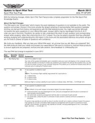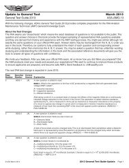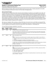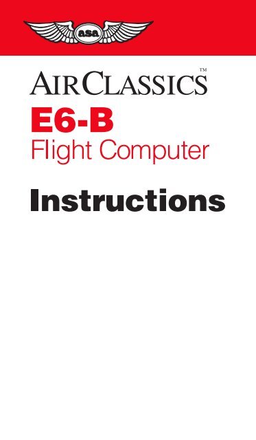
E6-B Flight Computer Instructions - Aviation Supplies & Academics
E6-B Flight Computer Instructions - Aviation Supplies & Academics
E6-B Flight Computer Instructions - Aviation Supplies & Academics

Create successful ePaper yourself
Turn your PDF publications into a flip-book with our unique Google optimized e-Paper software.
<strong>E6</strong>-B <strong>Flight</strong> <strong>Computer</strong> <strong>Instructions</strong><br />
This instruction booklet can be used with the three<br />
different <strong>E6</strong>-B models available from ASA. If you<br />
have a different model than the one depicted, some<br />
parts of your computer may appear slightly different<br />
from the computers pictured in this booklet. However,<br />
the calculations are accomplished with the<br />
same method and produce the same answers.<br />
© 1992 – 2000 ASA<br />
<strong>Aviation</strong> <strong>Supplies</strong> & <strong>Academics</strong>, Inc.<br />
7005 132nd Place SE<br />
Newcastle, WA 98059-3153<br />
All rights reserved. Reproduction in whole or in part of this text is<br />
strictly prohibited and unlawful without the written permission of<br />
<strong>Aviation</strong> <strong>Supplies</strong> & <strong>Academics</strong>, Inc.<br />
ISBN 1-56027-421-2<br />
ASA-<strong>E6</strong>B<br />
2
Contents<br />
Page<br />
<strong>Instructions</strong> for Using ASA <strong>Flight</strong> <strong>Computer</strong>...... 4<br />
The Slide Rule Side .......................................... 5<br />
Time, Speed, and Distance Problems .............. 8<br />
Fuel Consumption Problems ........................... 11<br />
Conversions .................................................... 13<br />
Nautical to Statute Miles ............................ 13<br />
U.S. Gallons to Imperial Gallons ................ 15<br />
Quantity/Weight Conversions..................... 16<br />
Using the Altitude and Speed<br />
Correction Windows ........................................ 18<br />
True Airspeed and Density Altitude ................ 18<br />
Converting Mach Number to True Airspeed.... 20<br />
True Altitude .................................................... 21<br />
Feet Per Mile vs. Feet Per Minute................... 22<br />
Off-Course Problems ...................................... 24<br />
The Crosswind Table ...................................... 27<br />
The Wind Side of the Slide ............................. 28<br />
Determining Winds in <strong>Flight</strong> ............................ 32<br />
Answers to Sample Problems ......................... 37<br />
3
<strong>Instructions</strong> for Using ASA <strong>Flight</strong> <strong>Computer</strong><br />
Your ASA <strong>E6</strong>-B <strong>Flight</strong> <strong>Computer</strong> has two main<br />
parts: a circular slide rule side for making quick<br />
calculations, and a wind side for computing ground<br />
speed and wind correction angle. The slide portion<br />
of the circular slide rule side also includes quickreference<br />
material.<br />
Figure 1<br />
4
The Slide Rule Side<br />
The term “circular slide rule” shouldn’t be intimidating.<br />
This side of your computer simply consists of a<br />
rotating disk with numbers on the middle scale,<br />
which when set against similar numbers on the<br />
fixed portion (outer scale), allows you to solve<br />
problems of time, speed, and distance, calculate<br />
fuel consumption, and make conversions between<br />
measurements such as statute and nautical<br />
miles. The inner scale on the rotating disk is<br />
graduated in hours. The slide rule side also has<br />
“windows” that you will use to solve airspeed and<br />
altitude problems.<br />
You can see that the number 60 on the rotating<br />
disk is marked differently than the other numbers.<br />
That is because most of your problems will be<br />
concerned with time —“something” per hour, either<br />
miles or gallons. Before you get to that, you should<br />
learn how to read and interpret the numbers on both<br />
portions of the slide rule side.<br />
Rotate the disk until all of the numbers on the<br />
middle scale match up with the numbers on the<br />
outer scale —10 will be at the top. However, that<br />
number “10” may be read as “.1,” “1,” “100,” or<br />
“1,000” depending upon the context of the problem.<br />
For now, read it as 10. The next number to the right<br />
is 11, so each life (or mark) of calibration between<br />
the two numbers is equal to .1, and you would read<br />
them as 10.1, 10.2, 10.3, etc. If you were solving a<br />
problem involving 1,000 pounds of fuel, the number<br />
10 would be read as 1,000, and each calibration<br />
would be equal to 10 pounds, and the 11 would be<br />
read as 1,100 pounds. See Figure 1.<br />
5
Now look at the number 15 on the disk. Between 15<br />
and 16 each calibration mark is equal to .2 and<br />
would be read as 15.2, 15.4, etc. If you were solving<br />
a problem with an airspeed of 150 knots, the first<br />
calibration past 15 (150 in this case) would be 152.<br />
The spacing changes again at the number 30,<br />
where each calibration becomes .5, and at 60,<br />
where each calibration equals 1. Before you read a<br />
value from the disks, be sure you understand what<br />
each line of calibration is equal to.<br />
You will use the slide rule side to establish<br />
ratios. With the numbers matched, the ratio is 1 to<br />
1. Now set the number 60 (the rate arrow) directly<br />
opposite to (or, “lined-up” with) 12 on the outer disk<br />
(see Figure 2). Notice that all of the numbers on the<br />
outer disk are exactly twice the value of the numbers<br />
on the inner disk: 90 is opposite of 180, 15 is<br />
opposite of 30, 3.5 is opposite of 7.0. You will use<br />
these ratios in solving time-speed-distance and fuel<br />
consumption problems.<br />
Look at the inside scale on the disk, where the<br />
lines of calibration look like clock times: 9:00, 6:00,<br />
etc.—these express hours. The inner scale is in<br />
hours and the middle scale is in minutes. 1:10 is<br />
directly below 70; one hour and ten minutes is the<br />
same as seventy minutes. 5:00 is printed below 300<br />
minutes, and five hours is the same as 300 minutes.<br />
To convert minutes to seconds, place the rate arrow<br />
opposite to the minutes on the outer scale and read<br />
seconds opposite to the “seconds” arrow, just to the<br />
right of 35 on the inner scale.<br />
6
Figure 2. Line up the number 60 (the rate arrow) with<br />
the number 12 on the outer disk (or, scale).<br />
7
Time, Speed, and Distance Problems<br />
The rate arrow on the disk is always set to indicate a<br />
value per hour on the outer scale. There are three<br />
basic time-speed-distance problems. In two of these<br />
problems you know the rate, while in the third problem,<br />
the rate is part of the answer you are looking for.<br />
To find the Time En Route, let’s assume you<br />
know your airspeed is 150 knots (nautical miles per<br />
hour).<br />
1. Set the rate arrow to 150. See Figure 3.<br />
2. You have determined the distance to your<br />
destination to be 245 nautical miles. Speed<br />
and distance are always on the outer scale;<br />
245 is halfway between 24 and 25.<br />
3. Look directly opposite to that value on the<br />
inner scale to find the Time En Route. It is<br />
between 1:35 and 1:40. There are five calibration<br />
marks on the middle scale between<br />
1:35 and 1:40, and 245 NM on the outer scale<br />
is closest to the third calibration, or one hour<br />
and 38 minutes.<br />
To find out how far you can go if your fuel<br />
endurance is 4.5 hours and your ground speed is<br />
known to be 125 knots:<br />
1. Set the rate arrow at 125 on the outer scale.<br />
See Figure 4.<br />
2. Find 4:30 on the inner scale.<br />
3. The value on the outer scale is slightly more<br />
than 55. You know that 4 hours at 125 knots<br />
should cover 500 miles, so the outer scale is<br />
read as 500, not 50 or 5,000, which makes<br />
each large calibration mark worth 10 nautical<br />
miles. The answer is 564 nautical miles.<br />
8
Figure 3<br />
Figure 4<br />
9
In the final and most common type of time-speeddistance<br />
problem, the time and distance are known,<br />
and you need to solve for unknown speed. The<br />
rate arrow represents the answer. You will have<br />
flown between two known ground reference points<br />
26 NM apart and checked the time between them to<br />
be: 13 (thirteen minutes, that is, not thirteen hours).<br />
1. Set thirteen minutes on the middle scale opposite<br />
to 26 on the outer scale. See Figure 5.<br />
2. The rate arrow points to your ground speed,<br />
120 knots.<br />
Figure 5<br />
Try these time-speed-distance problems:<br />
(Answers are on Page 37)<br />
10<br />
SPEED TIME DISTANCE<br />
1. 125 KTS 524 NM<br />
2. 2:30 345<br />
3. 110 KTS 1:40<br />
4. 0:24 44<br />
5. 95 1:24
Fuel Consumption Problems<br />
Problems involving fuel consumption, fuel endurance,<br />
and fuel capacity are solved using the same<br />
numbers you used in the time-speed-distance problems.<br />
With the exception of time values, only the<br />
names change.<br />
Assume that your airplane’s Approved <strong>Flight</strong><br />
Manual indicates fuel consumption of 8.4 gallons<br />
per hour at a given power setting and that the usable<br />
fuel capacity is 64 gallons. How many hours endurance<br />
do you have in the tanks?<br />
1. Line up the rate arrow (“something per hour”)<br />
with 8.4 on the outer scale. See Figure 6.<br />
2. Now find 64 on the outer scale.<br />
3. Opposite of 64, read fuel endurance in hours:<br />
7:37 on the inner scale. The outer scale,<br />
which was used for speed and distance, is<br />
now used to indicate gallons per hour and<br />
fuel capacity.<br />
Figure 6<br />
11
When you paid for your fuel you noted on the<br />
delivery ticket that it took 32 gallons to top the tanks.<br />
You flew four hours and twenty minutes before<br />
stopping for fuel. What was the average fuel consumption?<br />
This time the rate arrow provides the<br />
answer.<br />
1. Set 4:20 on the inner scale (or 260 on the<br />
middle scale) opposite of 32 on the outer<br />
scale. See Figure 7.<br />
2. The rate arrow indicates the average fuel<br />
burn rate: 7.4 gallons per hour.<br />
Remember that fuel consumption is greater during<br />
the climb to altitude, so this average value does not<br />
accurately reflect fuel consumption in cruising flight.<br />
Figure 7<br />
Try these examples:<br />
(Answers are on Page 37)<br />
GALLONS PER HOUR TIME TOTAL USED<br />
1. 7.8 3:20<br />
2. 4:50 62<br />
3. 8.5 38<br />
4. 10 2:30<br />
5. 12 22<br />
12
Conversions<br />
You can’t solve a problem unless the values agree.<br />
You can’t mix statute and nautical miles, gallons<br />
and liters, or Fahrenheit and Celsius. Your ASA<br />
<strong>E6</strong>-B <strong>Flight</strong> <strong>Computer</strong> makes it possible for you to<br />
convert between values with simple settings of the<br />
middle scale.<br />
Nautical to Statute Miles<br />
Distances on sectional and world aeronautical charts<br />
are in statute miles. Your airspeed indicator usually<br />
reads in knots, or nautical miles per hour. It is easy<br />
to convert between the two values by using special<br />
markings on the slide rule side of your flight computer.<br />
Look on the outside scale near 70 for markings<br />
labeled NAUT and STAT. Set the known value<br />
under the appropriate arrow and read the converted<br />
value under the other. For example, to convert 90<br />
knots to statute miles per hour:<br />
1. Set the arrow marked NAUT opposite of 90<br />
on the middle scale.<br />
2. Read 103.5 under the STAT arrow. See<br />
Figure 8.<br />
Figure 8<br />
13
You can convert either nautical or statute miles to<br />
kilometers. Find the KM marking on the outer<br />
scale. Set the known value beneath the NAUT or<br />
STAT arrow as before, and read kilometers under<br />
the KM marking. For example, to convert 115 statute<br />
miles to kilometers:<br />
1. Set 115 opposite of the STAT arrow.<br />
2. Read 185 under the KM marking.<br />
See Figure 9.<br />
Figure 9<br />
Try these sample problems:<br />
(Answers are on Page 37)<br />
NAUT STAT KM<br />
1. 20<br />
2. 48<br />
3. 110<br />
14
U.S. Gallons to Imperial Gallons<br />
Your Approved <strong>Flight</strong> Manual lists fuel capacity in<br />
U.S. gallons, but in many countries fuel is delivered<br />
in Imperial gallons. Arrows marked U.S. GAL and<br />
IMP. GAL are provided on both middle and outer<br />
scales to help you convert between these quantities.<br />
Your tanks are placarded to hold 64 U.S.<br />
gallons. How many Imperial gallons will they hold?<br />
1. Line up the U.S. GAL arrow on the middle<br />
scale opposite the IMP. GAL arrow on the<br />
outer scale.<br />
2. Find 64 on the middle scale.<br />
3. Read 53.2 Imperial gallons on the outer scale<br />
(see Figure 10). Because Imperial gallons<br />
are larger than U.S. gallons, the number of<br />
U.S. gallons will always be larger.<br />
Figure 10<br />
You have purchased fuel in Canada and the delivery<br />
slip says 32 Imperial gallons. How many U.S.<br />
gallons have you purchased? Line up the IMP. GAL<br />
arrow with the U.S. GAL arrow. Find 32 on the<br />
15
middle scale and read 38.5 U.S. gallons on the<br />
outer scale.<br />
Quantity/Weight Conversions<br />
<strong>Aviation</strong> gasoline weighs 6 pounds per U.S. gallon.<br />
For weight and balance calculations, aviation gasoline<br />
weight-per-gallon can be determined by lining<br />
the U.S. GAL arrow on the middle scale with the<br />
FUEL LBS arrow on the outer scale. Fuel gallons<br />
are read on the middle scale and fuel weight on the<br />
outer scale. To find the weight of 32 U.S. gallons:<br />
1. Align the arrows.<br />
2. Read 192 pounds on the outer scale opposite of<br />
32 gallons on the middle scale. See Figure 11.<br />
Figure 11<br />
Similarly, oil weight may be determined by lining the<br />
U.S. GAL arrow on the middle scale with the OIL<br />
LBS arrow on the outer scale. Oil gallons are read<br />
on the middle scale and oil weight is read on the<br />
outer scale. To find the weight of 2 gallons (8 quarts)<br />
of oil:<br />
16
Figure 12<br />
1. Align the arrows.<br />
2. Read 15 pounds on the outer scale opposite of<br />
2 gallons on the middle scale. See Figure 12.<br />
Imperial gallon weight of fuel and oil may also be<br />
determined in the same manner by lining up the<br />
IMP. GAL arrow on the middle scale with the FUEL<br />
LBS or OIL LBS arrow on the outer scale.<br />
You can convert liters to U.S. gallons, pounds<br />
to kilograms, or feet to meters by aligning the<br />
appropriate arrows on the middle and outer scales.<br />
For example, to convert pounds to kilograms:<br />
1. Find the arrows marked LBS. and KG, and<br />
line them up.<br />
2. Any value in pounds on the outer scale will be<br />
opposite of its converted value in kilograms<br />
on the middle scale: 2,000 lbs is 901 kg, and<br />
160 kg is 351 lbs.<br />
3. The same procedure is followed for the other<br />
conversions.<br />
17
Using the Altitude and Speed<br />
Correction Windows<br />
Altimeters and airspeed indicators are designed to<br />
give correct indications under standard conditions<br />
at sea level. The consistency of the earth’s atmosphere<br />
does not change linearly as you gain altitude;<br />
its density is affected by variations in temperature<br />
and pressure. The <strong>E6</strong>-B provides windows on<br />
the slide rule side so you can allow for these<br />
variations when converting calibrated airspeed to<br />
true airspeed or indicated altitude to true altitude.<br />
True Airspeed and Density Altitude<br />
Note that the outer scale of your flight computer is<br />
marked TAS (true airspeed) and the middle scale is<br />
marked CAS (calibrated airspeed).<br />
The Approved <strong>Flight</strong> Manual for your airplane<br />
contains a conversion table that allows you to<br />
convert indicated airspeed to CAS. The difference<br />
is greatest at low speeds and becomes negligible at<br />
cruise speeds. To determine true airspeed you<br />
must first know the pressure altitude. Set your<br />
altimeter to 29.92 and read the altitude indicated;<br />
that is the pressure altitude. Note the outside air<br />
temperature and convert it to Celsius using the<br />
conversion scale at the bottom of the flight computer.<br />
1. Set the pressure altitude in the window opposite<br />
the outside air temperature in Celsius.<br />
2. Without moving the computer’s scales, read<br />
the true airspeed on the outer scale opposite<br />
CAS on the middle scale.<br />
18
Figure 13<br />
3. Read the density altitude over the arrow in<br />
the DENSITY ALTITUDE window. See Figure<br />
13.<br />
Figure 13 shows a pressure altitude of 15,000 feet<br />
set opposite an outside air temperature of -15°C. A<br />
calibrated airspeed of 145 knots converts to a true<br />
airspeed of 183 knots and a density altitude of<br />
15,000 feet under these conditions.<br />
Here are some sample problems:<br />
(Answers are on Page 37)<br />
PRESSURE DENSITY<br />
ALTITUDE TEMP CAS TAS ALTITUDE<br />
1. 14,000 5°C 160<br />
2. 20,000 -20°C 200<br />
3. 8,000 15°C 150<br />
19
Converting Mach Number to True Airspeed<br />
To convert Mach Number to True Airspeed (or vice<br />
versa), rotate the inner dial until you see the Mach<br />
No. Index inside the airspeed correction window on<br />
the inner dial. Line up the true or outside air temperature<br />
(do not use Indicated Air Temperature)<br />
opposite this Mach No. Index. Mach Number on the<br />
inner scale reads opposite True Airspeed (in nautical<br />
miles per hour) on the outer scale. In Figure 14, at an<br />
outside air temperature of +15°C and Mach 1 (10 on<br />
the inner scale), read 661 knots on the outer scale.<br />
Figure 14<br />
20
True Altitude<br />
When the air is colder than standard your altimeter<br />
can mislead you into thinking you are higher than<br />
you actually are. Determine true altitude by the<br />
following steps:<br />
1. Determine pressure altitude by setting 29.92<br />
momentarily on the altimeter.<br />
2. Set pressure altitude next to outside air temperature<br />
in the altitude correction window.<br />
3. Subtract station altitude from indicated/calibrated<br />
altitude to determine calibrated altitude<br />
AGL.<br />
4. Find calibrated altitude AGL on the middle<br />
scale and read the correction to station altitude<br />
on the outer scale.<br />
5. Add the correction to station altitude to get<br />
true altitude MSL.<br />
Figure 15<br />
21
If the station altitude is unknown, read calibrated<br />
altitude MSL on the middle scale and true altitude<br />
MSL on the outer scale.<br />
In Figure 15 the pressure altitude is 10,000 feet,<br />
station altitude is 5,000 feet, outside air temperature is<br />
-19°C, and your indicated (calibrated) altitude is 12,000<br />
feet. The difference between 5,000 feet station altitude<br />
and 12,000 feet indicated altitude is 7,000 feet. Opposite<br />
7,000 feet on the middle scale read correction to<br />
station altitude (6,600 feet) on the outer scale—5,000<br />
feet plus 6,600 feet equals 11,600 feet true altitude.<br />
CAUTION: If the temperature between the surface<br />
and the aircraft does not decrease at the<br />
standard rate of 2°C per 1,000 feet or if the pressure<br />
at flight level is nonstandard, reliance on a computer<br />
solution to determine obstruction clearance<br />
can be very hazardous.<br />
Find True Altitude:<br />
(Answers are on Page 38)<br />
INDICATED/<br />
PRESSURE CALIBRATED STATION TRUE<br />
ALTITUDE ALTITUDE TEMP ALTITUDE ALTITUDE<br />
1. 10,500 10,000 -20°C 5,000<br />
2. 12,000 11,000 -30°C 3,000<br />
3. 8,000 7,600 -15°C (unknown)<br />
Feet Per Mile vs. Feet Per Minute<br />
Because aircraft performance characteristics vary<br />
dramatically between types, the FAA establishes<br />
climb and descent requirements in feet per mile,<br />
rather than in feet per minute. A climb of 300 feet<br />
per mile will result in a 3° climb angle for any aircraft;<br />
a light trainer climbing at that angle at 90 knots<br />
22
ground speed will indicate 450 feet per minute,<br />
while a jet following that same gradient at 240 knots<br />
ground speed will show a vertical speed of 1,200<br />
feet per minute.<br />
You can convert feet per mile to feet per minute<br />
by placing the rate arrow opposite to the ground<br />
speed, finding the feet per minute value on the outer<br />
scale lined up with the feet per mile value on the<br />
middle scale. Try these two examples:<br />
1. Set the rate arrow opposite of 90.<br />
2. Find 300 feet per mile on the middle scale<br />
(see Figure 16).<br />
3. The climb rate in feet per minute, 450, is<br />
found on the outer scale opposite of 300.<br />
1. Set the rate arrow at 240 knots.<br />
2. Look above 300 on the middle scale.<br />
3. You should find a vertical speed of 1,200 feet<br />
per minute.<br />
Figure 16<br />
23
(Answers are on Page 38)<br />
GROUND SPEED FEET PER MILE FEET PER<br />
REQUIRED MINUTE<br />
1. 120 350<br />
2. 100 250<br />
3. 150 300<br />
Off-Course Problems<br />
When you navigate by pilotage, you will occasionally<br />
find your airplane has drifted off the planned<br />
course due to the wind. If you find yourself over a<br />
landmark to one side of the course line you should<br />
be able to estimate the distance you have drifted off<br />
course (the scale of sectional charts is 8 statute<br />
miles to the inch), and your flight log should help<br />
determine how far you have flown and how far it is<br />
to your destination.<br />
Two computer setups are required. The first will<br />
give you the heading correction necessary to offset<br />
wind drift, or “course to parallel.” On the middle<br />
scale, set the distance flown opposite of the distance<br />
off course on the outer scale; the rate arrow<br />
points to the degrees of heading change to parallel<br />
the course.<br />
Example: After flying 125 miles, you note that<br />
you are 8 miles off course. (See Figure 17.)<br />
1. Set 125 on the middle scale to line up with 8<br />
on the outer scale.<br />
2. Read approximately 3.8° at the rate arrow.<br />
The second setup will give you the additional heading<br />
change required to fly back to the original course<br />
line. On the middle scale, set distance remaining<br />
24
Figure 17<br />
opposite of the distance off course; read additional<br />
degrees of heading change opposite of the rate<br />
arrow. Add the two answers and apply the result to<br />
your heading.<br />
Example: Your destination is 235 miles ahead<br />
(see Figure 18 on the next page).<br />
1. Set 235 on the middle scale opposite 8 on the<br />
outer scale.<br />
2. Read 2.4° at the rate arrow.<br />
3. Change course 6° (3.8 + 2.4) toward the<br />
course line and, if the wind doesn’t change,<br />
you will rejoin the original course line as you<br />
approach the destination.<br />
See also Figure 19 on the next page.<br />
25
Figure 18<br />
Figure 19 shows the setups in equations.<br />
Figure 19<br />
26
The Crosswind Table<br />
To determine headwind, tailwind or crosswind<br />
component quickly and easily, you must know the<br />
angle between your course and the reported wind<br />
direction. You also must know the reported wind<br />
velocity. This will be especially helpful in anticipating<br />
the effect of wind when landing, because wind<br />
reported by a tower, flight service station, or ATIS is<br />
surface wind. These reports give wind direction in<br />
relation to magnetic north and can be compared to<br />
your airplane’s heading indicator without correction.<br />
If you use the table with winds aloft, remember<br />
that those winds are reported in relation to true north<br />
and you must apply variation before comparing<br />
them to the heading indicator.<br />
Figure 20<br />
27
28<br />
Example: The ATIS reports the wind as from<br />
230° at 14 knots with runway 18 in use. In the<br />
column headed by 50° (see Figure 20) there is<br />
a box for 10 knots and a box for 20 knots.<br />
Interpolating, the headwind component will be<br />
9.5 knots and the crosswind component will be<br />
11.5 knots. Those are “approximate” because<br />
the wind when you touch down will rarely be<br />
exactly what was reported.<br />
The Wind Side of the Slide<br />
Directions for use of the wind side are printed on the<br />
slide (see Figure 21). It provides a graphic method<br />
of solving problems in trigonometry and displaying<br />
the answers in a very useful form.<br />
To determine ground speed and wind correction<br />
angle you must know four things: true course,<br />
true airspeed, true wind direction, and wind velocity.<br />
The winds aloft forecast provides the latter two; true<br />
course is measured directly on your sectional or<br />
WAC chart, and TAS is either converted from indicated<br />
airspeed in flight or taken from the airplane’s<br />
performance charts during preflight planning.<br />
Enter the wind first. Rotate the transparent disk<br />
until the reported wind direction lines up with the<br />
TRUE INDEX. Measure up from the grommet and<br />
make a dot equal to the wind velocity. Each line<br />
equals 1 knot on the <strong>E6</strong>-B, 2 knots on the paper<br />
(<strong>E6</strong>B-P) and micro (<strong>E6</strong>B-1) models, and 1 or 10<br />
knots on the high-speed <strong>E6</strong>-B slide accessory<br />
(<strong>E6</strong>B-SLIDE).<br />
Now rotate the transparent disk until the true<br />
course lines up with the TRUE INDEX, and move<br />
the slide up or down until the wind dot falls on the arc
–E<br />
TC +W VAR = MC<br />
–L<br />
MC +R WCA = MH<br />
MH ± DEV = CH<br />
Figure 21<br />
Note: Some slight variations exist on the <strong>E6</strong>-B models, but the<br />
calculations are the same; be sure to count the lines accurately.<br />
29
that represents the true airspeed. Read ground<br />
speed under the grommet. The wind correction<br />
angle is measured right or left of the center line. Be<br />
sure to count the degrees accurately—the value of<br />
each line changes at the 100, 150, or 250 knot arc,<br />
depending on the <strong>E6</strong>-B model you are using (see<br />
Note below Figure 21).<br />
Example: You have laid out a course on a<br />
sectional chart and measured it to be 090° true<br />
using your plotter. The winds aloft forecast<br />
calls for the wind at your chosen altitude to be<br />
230° at 18 knots, and the performance data for<br />
the airplane says that you can expect a true<br />
airspeed of 125 knots at that altitude.<br />
1. Set 230° at the TRUE INDEX.<br />
2. Using any convenient starting point, measure<br />
18 units up from the grommet toward the<br />
TRUE INDEX and make a dot at 18 units (see<br />
Figure 22).<br />
3. Rotate the transparent disk to bring 090° to<br />
the TRUE INDEX.<br />
4. Move the slide until the wind dot falls on the<br />
arc for 125 knots (see Figure 23 on Page 32).<br />
5. Read the ground speed of 138 knots under<br />
the grommet; the fact that the wind dot is<br />
below the grommet indicates a tailwind.<br />
6. The wind dot is 5° to the right, indicating that<br />
the true heading should be 095°. Now all you<br />
have to do is apply local magnetic variation to<br />
derive magnetic heading.<br />
If the upper winds forecast applies to your entire trip,<br />
simply use the wind dot in this manner with the true<br />
course for each leg.<br />
30
Figure 22<br />
Here are some sample problems:<br />
(Answers are on Page 38)<br />
TRUE<br />
WIND WIND TRUE TRUE GROUND<br />
DIREC. VELOCITY COURSE TAS HDG SPEED<br />
1. 240 38 300 165<br />
2. 040 43 150 140<br />
3. 330 25 020 180<br />
4. 110 18 260 225<br />
31
Figure 23<br />
Determining Winds in <strong>Flight</strong><br />
Winds aloft forecasts are frequently in error. If you<br />
have an autopilot and some free time, you can<br />
calculate the actual winds at your location and<br />
altitude. It helps if you have GPS, too.<br />
To solve an inflight wind problem you need your<br />
ground speed, true heading, true course, and true<br />
airspeed. Let’s assume your true course is 180°,<br />
your true heading is 160°, your last ground speed<br />
32
check came out to be 120 knots, and you calculate<br />
the true airspeed at your altitude to be 140 knots.<br />
1. Set 180° at the TRUE INDEX on the wind<br />
side of the computer.<br />
2. Move the slide until the grommet falls over<br />
the line marked 120. The true heading is 20°<br />
less than the true course, which means that<br />
you have a 20° left wind correction angle.<br />
3. With the grommet on the 120-knot ground<br />
speed line, find the point on the slide where<br />
the 20° left wind correction angle crosses the<br />
line marked 140 and make a pencil mark (see<br />
Figure 24 on the next page).<br />
4. Rotate the azimuth disk until the pencil mark<br />
is on the centerline between the grommet<br />
and the true index.<br />
5. Determine the wind velocity by counting the<br />
lines between the grommet and the pencil<br />
mark.<br />
6. Read the true wind direction under the true<br />
index. You should have a wind direction of<br />
104° and a wind speed of 50 knots (see<br />
Figure 25 on Page 35).<br />
If you have GPS, the direct track readout is used<br />
instead of true heading. Correct for variation, because<br />
the direct track information is magnetic.<br />
Sample problems:<br />
(Answers are on Page 38)<br />
TRUE TRUE GROUND WIND WIND<br />
HDG COURSE TAS SPEED DIREC. VELOCITY<br />
1. 320 315 140 128<br />
2. 175 160 150 115<br />
33
Figure 24<br />
34
Figure 25<br />
35
Notes<br />
36
Answers to Sample Problems<br />
Time-Speed-Distance Problems, Page 10<br />
1. 4 Hours and 12 Minutes<br />
2. 138 Knots<br />
3. 183 Nautical Miles<br />
4. 110 Knots<br />
5. 133 Nautical Miles<br />
Fuel Consumption Problems, Page 12<br />
1. 26 Gallons<br />
2. 12.8 GPH<br />
3. 4 Hours and 28 Minutes<br />
4. 25 Gallons<br />
5. 1 Hour and 50 Minutes<br />
Distance Conversion Problems, Page 14<br />
1. 23 Statute Miles, 37 Kilometers<br />
2. 41.7 Nautical Miles, 77.2 Kilometers<br />
3. 59.4 Nautical Miles, 68.4 Statute Miles<br />
Airspeed Conversion Problems, Page 19<br />
1. 204 Knots TAS, 16,000' DA<br />
2. 273 Knots TAS, 20,500' DA<br />
3. 174 Knots TAS, 9,800' DA<br />
37
Altitude Correction Problems, Page 22<br />
1. 9,750' True Altitude<br />
2. 10,350' True Altitude<br />
3. 7,200' True Altitude<br />
Feet per Mile vs. Feet per Minute Problems, Page 24<br />
1. 700 FPM<br />
2. 415 FPM<br />
3. 750 FPM<br />
Wind Problems, Page 31<br />
TRUE GROUND<br />
HDG SPEED<br />
1. 288 143<br />
2. 133 149<br />
3. 014 163<br />
4. 258 240<br />
Wind Problems, Page 33<br />
WIND WIND<br />
DIREC. VELOCITY<br />
1. 002 17<br />
2. 212 49<br />
38