REMEDIATION ACTION PLAN CALTEX REFINERIES (NSW) PTY ...
REMEDIATION ACTION PLAN CALTEX REFINERIES (NSW) PTY ...
REMEDIATION ACTION PLAN CALTEX REFINERIES (NSW) PTY ...

Create successful ePaper yourself
Turn your PDF publications into a flip-book with our unique Google optimized e-Paper software.
<strong>REMEDIATION</strong> <strong>ACTION</strong> <strong>PLAN</strong><br />
<strong>CALTEX</strong> <strong>REFINERIES</strong> (<strong>NSW</strong>) <strong>PTY</strong> LTD<br />
DREDGING IN BOTANY BAY<br />
Prepared by<br />
Caltex Refineries (<strong>NSW</strong>) Pty Ltd<br />
February 2013
Table of Contents<br />
Executive summary ............................................................................................................... 1<br />
1 Introduction .................................................................................................................... 2<br />
1.1 Project Overview ..................................................................................................... 2<br />
1.2 Objectives ............................................................................................................... 4<br />
1.3 Extent of Dredging Works ....................................................................................... 4<br />
1.4 Site Identification..................................................................................................... 6<br />
2 Site History .................................................................................................................... 7<br />
3 Site Conditions and Surrounding Environment ............................................................... 8<br />
3.1 Submarine Utilities and Infrastructure ..................................................................... 8<br />
3.2 Recreation .............................................................................................................. 9<br />
3.3 Areas of Ecological Significance ............................................................................. 9<br />
3.4 Sensitive Receptors .............................................................................................. 10<br />
4 Sub-soil Environments ................................................................................................. 11<br />
4.1 Regional Geology and Stratigraphy....................................................................... 11<br />
4.2 Acid Sulfate Soils .................................................................................................. 11<br />
5 Assessment Criteria ..................................................................................................... 13<br />
5.1 Basis for Assessment Criteria ............................................................................... 13<br />
5.2 Acceptance Criteria ............................................................................................... 15<br />
6 Existing Sediment Data ................................................................................................ 16<br />
6.1 Previous Investigations ......................................................................................... 16<br />
6.2 Sediment Characteristics ...................................................................................... 17<br />
6.3 Chemical Characteristics ...................................................................................... 20<br />
6.3.1 Tributyltin ....................................................................................................... 20<br />
6.3.2 Acid Sulfate Soils ........................................................................................... 21<br />
7 Remediation Options Appraisal .................................................................................... 22<br />
7.1 Overview of Issues and Objectives ....................................................................... 22<br />
7.2 Onshore Disposal ................................................................................................. 22<br />
7.3 Onshore Disposal after Treatment ........................................................................ 22<br />
7.4 Onshore Reuse ..................................................................................................... 22<br />
7.5 Partial Offshore Reuse .......................................................................................... 22<br />
7.6 Partial Offshore Disposal ...................................................................................... 23<br />
8 Preferred Remediation Approach ................................................................................. 24<br />
i
8.1 Overview of Preferred Remediation Options ......................................................... 24<br />
8.2 Works Overview .................................................................................................... 24<br />
8.2.1 Dredging Works ............................................................................................. 24<br />
8.2.2 Proposed Dredging Method ........................................................................... 25<br />
8.2.3 Sediment Reuse ............................................................................................ 26<br />
8.2.4 Sediment Disposal ......................................................................................... 29<br />
9 Environmental Management ........................................................................................ 30<br />
9.1 Dredge and Spoil Disposal Management Plan (DSDMP) ...................................... 30<br />
9.2 Use of Zero Overflow Dredging Methodology ........................................................ 31<br />
9.3 Physico-Chemical Monitoring and Stop-Work Triggers ......................................... 33<br />
9.4 Management of Acid Sulfate Soils ........................................................................ 33<br />
9.5 Mitigation and Management Measures ................................................................. 33<br />
9.6 Validation .............................................................................................................. 38<br />
10 Concluding Remarks ................................................................................................ 38<br />
Tables<br />
Table 5-1 Screening Levels ............................................................................................... 14<br />
Table 5-2 Sediment Quality High Values ........................................................................... 15<br />
Table 6-2 Summary of the Geochemical Analysis Results for TBT in Sediments .............. 20<br />
Table 6-3 Elutriate Testing Results .................................................................................... 21<br />
Table 8-1 Proposed Dredging Area, Depth and Volume .................................................... 25<br />
Table 9-1 Mitigation and Management Measures .............................................................. 34<br />
Figures<br />
Figure 1-1 Location of Port and Berthing Facility ............................................................... 3<br />
Figure 1-2 Area of Proposed Dredging Activities ............................................................... 5<br />
Figure 6-1 Sampling Locations (2009-2011) ................................................................... 18<br />
Figure 6-2 Sampling Locations (2012) ............................................................................ 19<br />
Figure 8-1 Sediment re-use locations.............................................................................. 28<br />
Figure 9-1 Distribution of Tributyltin across the Project Site ............................................ 32<br />
ii
Executive summary<br />
Caltex Refineries (<strong>NSW</strong>) Pty Ltd (Caltex) (ABN: 1 900 0108 725) maintains and operates an<br />
oil refinery (the Kurnell Refinery) located on the Kurnell Peninsula in New South Wales. Part<br />
of the refinery operation includes a Port and Berthing Facility for receiving crude oil and<br />
exporting intermediates and final products. The facility includes a 1 km wharf; two fixed<br />
berths located either side of the wharf’s breasting island, a submarine (sub) berth, and an<br />
associated turning circle and approaches. This facility has been operational since 1956.<br />
Caltex proposes to upgrade the Kurnell Port and Berthing Facility to extend its operational<br />
life by improving the shipping capability. The proposed works will include both infrastructure<br />
works and dredging activities. The overall works are a State Significant Development, which<br />
requires the preparation of an Environmental Impact Statement (EIS). This Remediation<br />
Action Plan (RAP) has been prepared in conjunction with an Environmental Impact<br />
Statement (EIS) under the provisions of State Environmental Planning Policy 55 (SEPP<br />
N o 55) on the Remediation of Land.<br />
The dredging work will involve the excavation of sediments, some of which contain elevated<br />
contaminant concentrations. The objective of this RAP is to establish the management<br />
protocols for the excavation, transport and disposal of the dredged sediments, in order to<br />
complete the works in an environmentally acceptable manner.<br />
The activities which are the subject of this RAP include dredging the two fixed berths<br />
adjacent to the Wharf, the sub berth, the turning circle and approaches. There will be<br />
selected reuse of some dredged material to cover two exposed sections of the submarine<br />
fuel pipelines and to backfill a former anchor point at the approach to the sub berth.<br />
However, the majority of the sediment will be disposed offshore at the Sydney Offshore Spoil<br />
Ground, a process that is subject to a Sea Dumping Permit under the Commonwealth<br />
Environmental (Sea Dumping) Act 1981.<br />
The proposed dredging is being conducted to allow for safe shipping access. Dredging will<br />
be restricted to specific areas and to nominated depths with the extent and depth of dredging<br />
controlled by GPS management.<br />
The dredging is being conducted in accordance with an EIS that has been prepared to<br />
obtain planning consent for the proposed works. The EIS establishes the environmental<br />
conditions in the areas to be dredged and the mitigation and management measure that are<br />
required to reduce any adverse impacts of the proposed works. This RAP has been<br />
prepared to document the handling and disposal activities associated with the dredging.<br />
1
1 Introduction<br />
1.1 Project Overview<br />
Caltex Refineries (<strong>NSW</strong>) Pty Ltd (Caltex) maintains and operates an oil refinery (the Kurnell<br />
Refinery) located on the Kurnell Peninsula in New South Wales. The Kurnell Refinery<br />
facilities include a jetty structure known as the Kurnell Wharf, which along with the<br />
associated shipping berths form the Kurnell Port and Berthing Facility.<br />
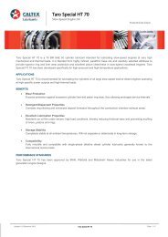
The location of the Port and Berthing Facility is shown on Figure 1-1. The Figure shows the<br />
Wharf and the areas around the Wharf that form the berths, approaches and turning circle,<br />
which are leased from the State Government. This area is used exclusively by Caltex for<br />
accessing and berthing ships to allow loading and unloading to take place.<br />
The Kurnell Port and Berthing Facility has been in service since 1956 and is limited in the<br />
draft and size of ships that can be received, both through design and the natural<br />
environmental changes that have occurred in the area over time. The deposition of<br />
sediment, which has occurred since the berths were previously dredged 40 years ago, now<br />
restricts safe access.<br />
Caltex proposes to undertake works on the Facility to improve the shipping capability. This<br />
will include both upgrade work to the berthing infrastructure and dredging activities. The<br />
overall works are classed as State Significant Development, which requires the preparation<br />
of an Environmental Impact Statement (EIS) to support the development application for the<br />
proposed works. In addition to the EIS, the proposed dredging requires the preparation of a<br />
Remediation Action Plan (RAP) under the provisions of State Environmental Planning Policy<br />
55 (SEPP N o 55) on the Remediation of Land as the proposed works would involve the<br />
removal and dispersal of land that is contaminated’ they constitute ‘remediation’..<br />
This RAP has been prepared in conjunction with the EIS, both documents addressing<br />
potential impacts resulting from the proposed works. The RAP has been prepared in<br />
accordance with the Guidelines for Consultants Reporting on Contaminated Sites (<strong>NSW</strong><br />
Environment Protection Authority (EPA), 1997).<br />
2
This drawing is subject to COPYRIGHT.<br />
/<br />
Botany<br />
Bay<br />
Sydney<br />
B o t a n y B a y<br />
Breasting Island<br />
Fixed<br />
Berth #2<br />
Silver Beach<br />
KURNELL<br />
Sub<br />
Berth #3<br />
0 100 200 400<br />
Datum: GDA94<br />
Grid: MGA Zone 56<br />
600 800<br />
Meters<br />
!.<br />
Turning<br />
Circle<br />
KURNELL PORT AND BERTHING PROJECT<br />
Fixed<br />
Berth #1<br />
Kurnell Wharf<br />
Kurnell Refinery<br />
B o t a n y B a y S h i p p i n g C h a n n e l<br />
Approaches<br />
Project Site<br />
Kamay Botany Bay<br />
National Park<br />
Whilst every care is taken by URS to ensure the accuracy of the digital data, URS makes no representation or warranties about its accuracy, reliability, completeness, suitability for any particular purpose and disclaims all responsibility<br />
and liability (including without limitation, liability in negligence) for any expenses, losses, damages (including indirect or consequential damage) and costs which may be incurred as a result of data being inaccurate in any way for any<br />
reason. Electronic files are provided for information only. The data in these files is not controlled or subject to automatic updates for users outside of URS.<br />
BOTANY BAY, <strong>NSW</strong><br />
File No: 43177771.073.mxd Drawn: STB Approved: CF Date: 19/02/2013<br />
Legend<br />
Project Site<br />
Dredge Footprint<br />
Submarine Fuel Pipelines<br />
!. Former Anchor Point<br />
Exposed Pipeline<br />
Source: Aerial Imagery from Bing Maps © 2010 Microsoft<br />
Corporation and its data suppliers and Nearmap Hypertiles 2012.<br />
LOCATION OF PORT AND<br />
BERTHING FACILITY<br />
Figure:<br />
1-1<br />
Rev. A A4
1.2 Objectives<br />
The dredging work will involve the excavation of sediments, some of which contain elevated<br />
concentrations of contaminants, specifically lead, zinc mercury and tributlytin (TBT).<br />
The objective of this RAP is to establish the management protocols for the excavation,<br />
transport and disposal of the dredged sediments so as to minimise potential adverse impacts<br />
to recreational users of the bay and marine ecosystems. This RAP has been developed to<br />
satisfy a scope of work item, as presented in the EIS, which is submitted under a separate<br />
cover.<br />
1.3 Extent of Dredging Works<br />
The proposed works aim to extend the operational life of the Kurnell Port and Berthing<br />
Facility and to improve the current shipping capability to meet existing and future transport<br />
fuels demands in both New South Wales (<strong>NSW</strong>) and the Australian Capital Territory (ACT).<br />
To achieve this, Caltex is proposing upgrading of the berthing infrastructure and targeted<br />
dredging associated with the port and berthing facility, within Botany Bay. The dredging<br />
activities that are the subject of this RAP include:<br />
• dredging within the two fixed berths adjacent to the Wharf, within the sub berth and<br />
within the turning circle and approaches;<br />
• selective reuse of some dredged material to cover two exposed sections of the<br />
submarine fuel pipelines and to backfill a former anchor point at the approach to the sub<br />
berth; and<br />
• disposal of the dredged material offshore, which is subject to a Sea Dumping Permit.<br />
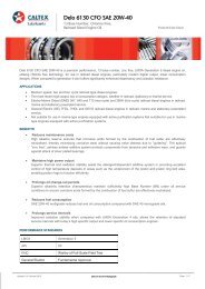
The volume of material that will be excavated during the dredging activities is approximately<br />
150,000 m 3 . The area of the proposed dredging activities is presented on Figure 1-2, which<br />
shows the position of the three berths along with the associated approaches and turning<br />
circle that provide access to and from the berths.<br />
4
This drawing is subject to COPYRIGHT.<br />
Breasting<br />
Island<br />
Whilst every care is taken by URS to ensure the accuracy of the digital data, URS makes no representation or warranties about its accuracy, reliability, completeness, suitability for any particular purpose and disclaims all responsibility and liability (including without limitation, liability in negligence) for any expenses,<br />
losses, damages (including indirect or consequential damage) and costs which may be incurred as a result of data being inaccurate in any way for any reason. Electronic files are provided for information only. The data in these files is not controlled or subject to automatic updates for users outside of URS.<br />
KURNELL PORT AND BERTHING PROJECT<br />
BOTANY BAY, <strong>NSW</strong>.<br />
File No: 43177815.074.mxd Drawn: STB Approved: SM Date: 19/02/2013<br />
Source:<br />
Image supplied by Worley Parsons: 301015-03067-MA-DWG-148012-C.pdf<br />
AREA OF PROPOSED<br />
DREDGING ACTIVITIES<br />
Figure:<br />
1-2<br />
Rev. A A4
1.4 Site Identification<br />
The Kurnell Refinery is located on the southern shore of Botany Bay, south of the Sydney’s<br />
Central Business District (CBD) (Figure 1-1). The Wharf extends approximately 800 m into<br />
Botany Bay to the west of Sutherland Point. Fixed Berths 1 and 2 are located either side of<br />
the Wharf, beyond which are the approaches (including a turning circle) and the sub-berth.<br />
The Port and Berthing Facility occupies land leased form the <strong>NSW</strong> State Government. The<br />
schedule within this lease describes the location of the land as being:<br />
“within the Parish of Sutherland, County of Cumberland, Sutherland Shire comprising<br />
Portion 995 being of 10 acres, 2 roods and 22 perches shown on plan C. 7000-2030<br />
Department of Lands.”<br />
6
2 Site History<br />
Botany Bay has strong Aboriginal and historic heritage associations. Today, the Bay has a<br />
diverse and mixed use. It is one of Sydney’s major commercial, industrial and port areas as<br />
well as being home to the international airport. The waters of the Bay are recreationally<br />
fished and licensed for aquaculture use. There are also a number of pipelines, cables and<br />
submarine structures that traverse the seabed.<br />
The majority of the project site falls within ‘unincorporated land’, which means that it does<br />
not fall under the jurisdiction of any local authorities in <strong>NSW</strong>. A small part of the project site<br />
to the south falls within Sutherland Shire Local Government Area (LGA), however the zoning<br />
for this part of the LGA is controlled by the State Environmental Planning Policy for the<br />
Kurnell Peninsula and is not covered under the Sutherland Shire Local Environment Plan<br />
(LEP).<br />
Caltex operates and maintains the project site within Botany Bay under an agreement made<br />
under of the Australian Oil Refinery Limited Agreement Ratification Act 1954. This allows<br />
Caltex to use Botany Bay as a Port and Berthing Facility.<br />
The location of the proposed dredging works is wholly within Botany Bay, in an area that has<br />
only formally been occupied by Caltex; however, there are other significant commercial<br />
facilities around Botany Bay including:<br />
• Port Botany, north of the project site which is one of <strong>NSW</strong>’s major three ports;<br />
• Sydney (Kingsford-Smith) Airport’s main and parallel runways, which extend into the Bay<br />
on a reclaimed peninsula; and<br />
• The Kurnell Refinery and the Sydney (Kurnell) Desalination Plant, which are located on<br />
the Kurnell Peninsula south and south west of the project site, respectively.<br />
The other major land use in the area is an aquaculture lease, which occupies 4 ha adjacent<br />
to the Kurnell Wharf. Although this lease is active, the site is not currently being farmed.<br />
7
3 Site Conditions and Surrounding Environment<br />
Botany Bay covers an area of approximately 4,600 hectares located 10 km south of the<br />
Sydney’s CBD. The Bay is located within the Sydney Metropolitan Catchment Management<br />
Area (SMCMA) and is designated a Special Port Area (Sydney Ports, 2012).<br />
Botany Bay is a wide, shallow estuary exposed to winds from all directions and waves from<br />
the adjacent high-energy coastal zone. Waves and currents determine the sediment erosion,<br />
deposition and transport patterns of the Bay and therefore the ultimate fate of sediments.<br />
Previous developments, most notably within northern Botany Bay, have modified the<br />
foreshores and substantially changed the local hydrodynamics. Any future changes to the<br />
Bay’s bathymetry (depth) and shoreline could further affect hydrodynamic conditions and the<br />
transport of sediment, potentially impacting the stability of the beaches and infrastructure.<br />
Currents within Botany Bay are predominantly tide, wind and river generated. Current<br />
velocities are generally exceptionally low (< 2 centimetres per second) and are influenced<br />
by:<br />
• the tidal flow to and from the Georges River in high rainfall periods;<br />
• long-period waves originating offshore in storm surges; and<br />
• wind action (which depends on the strength, fetch and duration of the wind). Botany Bay<br />
is exposed to winds over large stretches of open water (fetches) and wind-driven<br />
currents assist in the exchange and mixing of the estuarine waters in the Bay.<br />
Maximum tidal velocities are likely to only cause a localised re-suspension of the sandy subbenthic<br />
substrate that is predominant throughout sediments in the Bay.<br />
A large extent of Botany Bay is relatively shallow (0 to 4 m below Chart Datum (CD)). The<br />
exception is around the entrance from the Pacific Ocean, where the main channel depth<br />
increases to around 18 to 20 m below CD. This is partially natural and partially as a result of<br />
active dredging that has taken place to form the main shipping channel, the approaches and<br />
berths for the Kurnell Wharf.<br />
3.1 Submarine Utilities and Infrastructure<br />
No submarine utilities or infrastructure are known to cross the dredge footprint, with the<br />
exception of a crude oil submarine pipeline that connects the Refinery’s tanks to the sub<br />
berth and the two fixed berths. The next nearest major submarine infrastructure are the<br />
existing, Refinery submarine fuel pipelines that run west of the project site departing west<br />
from the Kurnell Wharf immediately south of the fixed berths. The Sydney (Kurnell)<br />
Desalination Plant includes a water supply pipeline, which crosses the Bay between Silver<br />
Beach and Kyeemagh, also west of the project site. Energy Australia’s 132 kV submarine<br />
power cable runs to the east of the project site.<br />
8
3.2 Recreation<br />
Recreational fishing is permissible in much of the Bay including the waters adjacent to the<br />
project site. No recreational fishing is permitted within the project site due to a 100 m Marine<br />
Security Zone around the berths and wharf. There are nominally 10 amateur fishing and<br />
angling groups that launch from close to the project site and use the Bay.<br />
3.3 Areas of Ecological Significance<br />
Botany Bay is considered to be the largest estuarine wetland in Sydney. It supports<br />
extensive aquatic marine and freshwater coastal habitat.<br />
There are several key areas of ecological importance within the Bay. The key areas of note<br />
in close proximity to the proposed works include: Towra Point Nature Reserve; Towra Point<br />
Aquatic Reserve; Cape Banks Aquatic Reserve; Bare Island; Taren and Dolls Point; areas of<br />
Seagrass Beds; and Kamay Botany Bay National Park.<br />
• Towra Point Nature Reserve is a Ramsar-listed site managed by <strong>NSW</strong> Office of<br />
Environment and Heritage (OEH). The Ramsar Convention was held in 1971 with the<br />
purpose of identifying areas of international importance for coastal wetlands. The Towra<br />
Point Nature Reserve is located to the west of Kurnell Peninsula and is the largest<br />
wetland of its type in the Sydney Basin. The reserve contains vegetation types that are<br />
now rare in the area and includes a variety of habitats such as seagrass beds,<br />
mangroves, saltmarshes, dune woodlands, she-oak Casuarina spp forest, littoral<br />
rainforest, sand dune grasslands and migratory wading bird habitats (DECCW, 2010).<br />
• Towra Point Aquatic Reserve is managed by <strong>NSW</strong> Department of Primary Industries<br />
(DPI) (Fisheries) and includes both an area zoned as an ‘aquatic wildlife refuge zone’<br />
and a ‘sanctuary zone’. The aquatic wildlife refuge zone extends around Towra Point<br />
Nature Reserve and extends into the Bay area, while the sanctuary zone occurs within<br />
the estuary. The reserve is considered to support high levels of aquatic biodiversity.<br />
More than 230 species of fish have been recorded within the reserve (<strong>NSW</strong> OEH<br />
National Parks and Wildlife Services (NPWS), 2012).<br />
• Seagrass Beds in Botany Bay: There is a higher coverage of seagrass about 3 km back<br />
from the estuary entrance close to the project site. The seagrass forms nursery grounds<br />
for many commercial fish and crustacean species and provides key habitat for a number<br />
of protected marine species including seahorses, pipefish and weedy sea-dragons.<br />
Research has determined that 257 ha (58%) of the seagrass beds in the Bay have been<br />
destroyed as a result of erosion, coastal works, elevated nutrients and sea urchin<br />
grazing. The most significant seagrass beds that are relevant to the dredge footprint are<br />
those containing strapweed Posidonia australis. This species was listed as an<br />
endangered population in 2010 under the <strong>NSW</strong> Fisheries Management (FM) Act 1994.<br />
This species was found to be located within the seagrass beds south of the dredge<br />
footprint.<br />
• Kamay Botany Bay National Park is located on northern and southern headlands of the<br />
Kurnell Peninsula. The Park is managed by <strong>NSW</strong> OEH NPWS and contains rich diverse<br />
ecosystems including cliffs and rock platforms, dunes, freshwater streams and swamps<br />
9
and wet forest. These provide habitat for a number of threatened species (Sutherland<br />
Shire Environment Centre (SSEC), 2008). It also includes the area of Bare Island<br />
located off the northern headland of the National Park.<br />
• Cape Banks Aquatic Reserve was established as a marine research site in the 1940s<br />
and includes rock platforms, crevices, rock pools, boulder and cobble shorelines. Some<br />
recreational fishing is permitted in the reserve.<br />
• Dolls Point and Taren Point are located where the Georges River enters the Bay. They<br />
are both key habitat within the Bay area and contain a diverse assemblage and<br />
population of shorebirds.<br />
3.4 Sensitive Receptors<br />
A number of native and Commonwealth and State-listed threatened biota have been<br />
recorded in and around the Botany Bay area. The notable native and threatened marine<br />
species in the area include:<br />
• a number of vulnerable, endangered and critically endangered birds (including Osprey,<br />
Little Penguin, Little Tern, Grey Tattler, Petrels, Shearwaters, Pied and Sooty<br />
Oystercatcher etc.);<br />
• the Australian and New Zealand fur seal;<br />
• a range of seagrass species;<br />
• a number of marine fish species (including 1 ray-finned fish);<br />
• a number of common marine invertebrates;<br />
• marine turtles (including the Green Turtle, Loggerhead Turtle and Leatherback Turtle);<br />
• Dugong;<br />
• Grey Nurse Shark; and<br />
• a number of cetaceans (i.e. whales (including the Humpback and Southern Right<br />
Whales) and dolphins).<br />
10
4 Sub-soil Environments<br />
4.1 Regional Geology and Stratigraphy<br />
Botany Bay is located in the Sydney Basin, which is a Palaeozoic to Mesozoic, trending<br />
trough located between the New England Fold Belt to the north east and the Lachlan Fold<br />
Belt to the west.<br />
The Botany Basin forms a specific sub unit of the Sydney Basin and is bounded by<br />
Centennial Park to the north, Randwick and Matraville to the east, Alexandria and Rockdale<br />
to the west, and the Kurnell Peninsula and part of Sutherland Shire to the south.<br />
The regional geology across the Botany Basin comprises Triassic age Hawkesbury<br />
Sandstone overlain by drift Quaternary deposits (Sydney 1:100,000 Geological Sheet). The<br />
sandstone comprises cross-bedded, medium-to-coarse quartz sand, with minor shale and<br />
laminate beds. The Quaternary deposits are up to 160 m in thickness and comprise sand,<br />
silty-sand, clayey-sand and clay with lenses of peat.<br />
The upper sediment layer of the Bay (to depths of approximately 7 m) comprise of loose<br />
estuarine sand and silty sand. Occasional stiff clay lenses, peat deposits and shelly sand<br />
beds appear within these sediments. This layer is overlying dense coarse sand and siltysand<br />
(up to 30 m in thickness).<br />
There is some variability in the geology and sedimentology across Botany Bay. At the mouth<br />
and central portions, the sediments comprise a mixture of modern and relict sand and<br />
biogenic material. The sediments are largely derived from the weathered Hawkesbury<br />
Sandstone. In low-energy areas, including the embayments on the southern shoreline close<br />
to the project site, the sediments are characterised by silty deposits and occasional lenses of<br />
peat.<br />
Previous sampling undertaken at the project site indicates the sedimentology and<br />
stratigraphy is typical and representative of the characteristics of the wider Bay area.<br />
Borehole sampling recorded that the upper sand layers are underlain by fissured clays and<br />
residual soils, with bedrock (sandstone) occurring between 25 -35 m.<br />
4.2 Acid Sulfate Soils<br />
The inundation of iron-rich soil by saline waters containing sulphates can lead to the<br />
formation of pyrite (iron sulphides). These sulphides are present across the Bay and are<br />
typical of the silty deposits and peat encountered around its periphery.<br />
Materials containing sulphides that remain undisturbed, submerged, or buried in the absence<br />
of oxygen (anoxic), do not pose a threat to the environment and are known as Potential Acid<br />
Sulfate Soil (PASS). However, if PASS are disturbed and exposed to oxygen, the sulphides<br />
may oxidise and produce sulphuric acid and iron-rich leachate. At this point they become<br />
Actual ASS (AASS). The resulting low pH conditions in the soil and local groundwater can<br />
subsequently leach metals from soils and cause adverse environmental effects in nearby<br />
surface waters.<br />
11
A review of the Acid Sulfate Soil Risk Map: Botany Bay indicates that land below the mean<br />
high water mark is at a high risk of containing PASS. The presence of PASS within the<br />
project site was confirmed through laboratory analysis, with the presence of AASS confirmed<br />
within the fixed berths.<br />
12
5 Assessment Criteria<br />
5.1 Basis for Assessment Criteria<br />
The criteria used to assess the sediments within the project site were adopted from the<br />
National Assessment Guidelines for Dredging (NAGD, the Guidelines) (Department of the<br />
Environment, Water, Heritage and the Arts, 2009). Through the Sea Dumping Act, the<br />
Australian Government assesses proposals to load, transport and dispose of wastes and<br />
other matter at sea. The Sea Dumping Act also permits acceptable activities and places<br />
conditions of approval to mitigate and manage environmental impacts.<br />
The NAGD sets out the framework for the environmental impact assessment and permitting<br />
of the ocean disposal of dredged material. The framework includes:<br />
• evaluating alternatives to ocean disposal;<br />
• assessing loading and disposal sites;<br />
• assessing potential impacts on the marine environment and other users; and<br />
• determining management and monitoring requirements.<br />
The NAGD are intended to provide greater certainty about the assessment and permitting<br />
process, as well as providing guidance on opportunities for longer-term strategic planning.<br />
The Guidelines provide a decision-tree approach for assessing potential contaminants, that<br />
comprises of five phases.<br />
• Phase I involves reviewing existing information on the material proposed for sea disposal<br />
to determine which contaminants need investigation and to assess whether the existing<br />
information sufficiently characterises the sediments without further testing.<br />
• Phase II involves identifying and investigating the contaminants that could be present in<br />
the sediments within the proposed dredge area. A Sampling and Analysis Plan (SAP) is<br />
prepared and once approved by the Determining Authority it is enacted. Results from<br />
the investigation are then evaluated by comparison to the Screening Levels contained in<br />
the NAGD (presented in Table 5-1). The results are also compared against ambient<br />
baseline levels for sediments of comparable grainsize in the vicinity of the disposal site.<br />
• Phase III consists of elutriate and bioavailability testing and is undertaken when results<br />
of testing undertaken in Phase II exceed the Screening Levels. Elutriate testing<br />
assesses impacts to water quality. Test results are normally compared to the relevant<br />
ANZECC/ARMCANZ (2000) marine water quality trigger values for 95 per cent<br />
protection of species. Bioavailability testing is conducted to assess the potential risk to<br />
marine organisms from contaminant intake based on the identified sediment quality.<br />
There are a variety of methods available to investigate contaminant bioavailability. If<br />
tests indicate that the bioavailability of the relevant contaminants would produce adjusted<br />
exposure concentrations that are below the specified criteria, the dredged material is<br />
chemically acceptable for ocean disposal. If the bioavailability results indicate adjusted<br />
exposure concentrations that are above the criteria, the sediment is potentially toxic and<br />
the assessment proceeds to Phase IV.<br />
13
• Phase IV involves acute and chronic toxicity testing when results from Phase III indicate<br />
that the sediment is potentially toxic. It employs a minimum of three sensitive test<br />
organisms, representing the main contaminant exposure routes. If all tests are passed,<br />
the sediment is not considered toxic and is deemed chemically acceptable for ocean<br />
disposal.<br />
• Phase V is a weight-of-evidence assessment where there are no appropriate toxicity<br />
tests for particular contaminants or where scattered toxicity has been found throughout a<br />
dredge area and it is not associated with any hot spot.<br />
Bioaccumulation testing is undertaken when the sediment contains bio-accumulating<br />
substances, such as mercury, dioxins or organochlorine pesticides at levels exceeding the<br />
ANZECC/ARMCANZ 2000 Sediment Quality Guidelines (SQG), which provide High value<br />
thresholds, as detailed in Table 5-2. On this basis, it should be noted that bioaccumulation<br />
may be a concern even where toxicity has not been identified.<br />
Analytical Parameter<br />
Table 5-1 Screening Levels<br />
Screening Level<br />
(ISQG Trigger Value)<br />
METALS & METALLOIDS (mg/kg)<br />
Antimony 2<br />
Arsenic 20<br />
Cadmium 1.5<br />
Chromium 80<br />
Copper 65<br />
Lead 50<br />
Mercury 0.15<br />
Nickel 21<br />
Silver 1.0<br />
Zinc 200<br />
ORGANICS* (µg/kg)<br />
Total PCBs 23<br />
Pesticides DDD 2<br />
DDE 2.2<br />
Total DDT 1.6<br />
Dieldrin 280<br />
Chlordane 0.5<br />
Lindane 0.32<br />
Endrin 10<br />
Total polycyclic aromatic hydrocarbons (PAHs) 10 000<br />
Total petroleum hydrocarbons 550 mg/kg<br />
Tributyltin (as Sn) 9 µg Sn/kg<br />
RADIONUCLIDES** (sum gross alpha and gross beta) 35 Bq/g<br />
* Normalised to 1 per cent total organic carbon. Normalisation is only appropriate over the TOC range 0.2–10 per cent.<br />
** Maximum (Bq/g is becquerels per gram).<br />
14
Table 5-2 Sediment Quality High Values<br />
Contaminant SQG High Value Thresholds<br />
METALS & METALLOIDS (mg/kg)<br />
Antimony 25<br />
Cadmium 10<br />
Chromium 370<br />
Copper 270<br />
Lead 220<br />
Mercury 1<br />
Nickel 52<br />
Silver 3.7<br />
Zinc 410<br />
Arsenic 70<br />
ORGANOMETALLICS (µg/kg)<br />
Tributyltin (TBT) 70<br />
ORGANICS (µg/kg)<br />
Total PAHs 50 000 (45 000)<br />
Total DDT 46<br />
p.p’-DDE 27<br />
o,p’- + p,p’-DDD 20<br />
Chlordane 6<br />
Dieldrin 270 e / 620<br />
Endrin 120 e / 220<br />
Lindane 1.0<br />
Total PCBs –<br />
Total petroleum hydrocarbons (TPHs) NA<br />
5.2 Acceptance Criteria<br />
For the purposes of the sediment management works, sediments with contaminant<br />
concentrations below the SQG screening levels are deemed to be ‘clean’ and not to<br />
requiring any special management measures.<br />
15
6 Existing Sediment Data<br />
6.1 Previous Investigations<br />
Three recent sediment investigations were undertaken by Worley Parsons (WP) in<br />
November 2009, March 2010 and November 2011 to determine the suitability of the<br />
proposed dredge material for unconfined sea disposal. A further investigation was<br />
undertaken by WP in 2012 to:<br />
• characterise the chemical properties of sediment from within the expanded areas of the<br />
dredge footprint; and<br />
• assess the bioavailability and toxicity of TBT with depth across the dredge footprint.<br />
The testing was undertaken in accordance with the NAGD in three separate Dredge Areas,<br />
as follows:<br />
• Dredge Area 1 - Approaches and Turning Circle (to be dredged to 12.8 m below CD);<br />
• Dredge Area 2: Sub-berth (to be dredged to 14.0 m below CD); and<br />
• Dredge Area 3: Fixed Berths 1 and 2 (to be dredged to 12.8 m below CD).<br />
WP undertook a preliminary investigation in November 2009 to characterise the physical<br />
properties and the types, concentrations and bioavailability of chemicals present in the<br />
proposed dredge material. The dredging requirements were determined from the Sydney<br />
Ports Corporation (SPC) (2007) hydrographic survey. This was the most recent hydrographic<br />
survey available at the time of sampling.<br />
The results of the preliminary investigation indicated that:<br />
• elevated concentrations of lead and zinc were present at concentrations exceeding the<br />
NAGD-low thresholds at location SS3A; and<br />
• elevated concentrations of tributyltin (TBT) and mercury were present at concentrations<br />
exceeding the NAGD-low thresholds at location SS3B.<br />
Further review of the hydrographic survey and subsequent discussions with the SPC pilots<br />
indicated that the dredge footprint was larger than the footprint investigated in the<br />
preliminary investigation. Additional sediment sampling was therefore undertaken in March<br />
2010 in accordance with an approved sampling and analytical plan (SAP). The analytical<br />
results indicated that whilst elevated concentrations of TBT were observed in elutriates,<br />
dilution modelling for material from the combined Dredge Areas 1, 2 and 3 determined that<br />
the concentrations of TBT in the dredge material would not be of concern to water quality<br />
during disposal at the Sydney Offshore Spoil Ground. In addition, toxicity was not observed<br />
by whole sediment or elutriate toxicity testing.<br />
Following the second sediment sampling program by WP in 2010 the need for additional<br />
sampling and testing was identified due to the proposed expansion of the dredge footprint.<br />
This additional, third investigation was undertaken to:<br />
16
• meet the required minimum number of samples specified in the guidelines due to the<br />
increase in dredge footprint since the previous sediment investigation; and<br />
• provide a better spatial and vertical coverage of the three proposed Dredge Areas.<br />
The third sediment sampling and analysis investigation was completed in November 2011.<br />
6.2 Sediment Characteristics<br />
The upper sediment layer across the project site has been subject to sediment<br />
characterisation by particle size distribution (PSD) analysis. A total of 38 sediment samples<br />
have been collected to the depth of the proposed dredging (14m below CD). The sampling<br />
locations are shown on Figure 6-1 (2009-2011) and Figure 6-2 (2012).<br />
The results of the PSD sampling determined the following:<br />
• The approaches, turning circle and sub berth predominantly comprise sand with a low<br />
distribution of fine particle sizes (less than 70 µm).<br />
• Sand with some gravel and fines are predominantly found within the fixed berths. The<br />
gravel comprises rock and shell fragments and the fines (found closer to the shoreline)<br />
comprise silt deposits (see Table 6-1).<br />
• Peat deposits (found at depths of between 0.6 – 1.5 m below the surface) were<br />
encountered at the southern end of fixed berth #1. These, along with the silt, remain<br />
buried and anoxic giving rise to PASS.<br />
Table 6-1 Summary of the Mean Particle Size Analyses<br />
Clay<br />
(2mm)<br />
(%)<br />
Cobbles<br />
(>6cm)<br />
(%)<br />
All Dredge Areas 5 2.3 10.2 86.1 4.9
This drawing is subject to COPYRIGHT.<br />
B o t a n y<br />
B a y<br />
/<br />
Sub<br />
Berth<br />
Turning<br />
Circle<br />
Fixed<br />
Berth #2 Fixed<br />
Berth #1<br />
Breasting Island<br />
Kurnell Wharf<br />
B o tt a n y<br />
B a y<br />
Approaches<br />
Project Site<br />
S h ii p p ii n g<br />
Botany Bay<br />
National Park<br />
ED SS2A<br />
ED SS4A<br />
ED SS2B<br />
ED SS4F<br />
ED SS5D<br />
ED SS5A<br />
ED SS5B<br />
EDEDEDEDED<br />
ED<br />
ED<br />
EDEDEDED<br />
ED<br />
VC4A ED SS4C<br />
EDEDED VC4A<br />
VC4A ED SS4D<br />
SS4B<br />
SS2D SS2C<br />
VC2A<br />
VC2A<br />
VC2A<br />
Sub<br />
Berth<br />
Fixed<br />
Berth #2<br />
0 37.5 75 150<br />
Datum: GDA94<br />
Grid: MGA Zone 56<br />
225 300<br />
Meters<br />
VC1B<br />
EDEDED ED SS4E<br />
VC1B<br />
VC4B<br />
EDEDED EDEDEDED VC4B<br />
VC4B<br />
ED SS1D<br />
ED SS1C<br />
Turning<br />
Circle<br />
VC4C ED SS4G<br />
EDEDEDED VC4C<br />
VC4C<br />
ED SS4H<br />
SS4I<br />
ED VC4D<br />
EDEDEDED VC4D<br />
ED SS4J<br />
VC4D<br />
VC5A<br />
EDEDED VC5A<br />
VC5A<br />
KURNELL PORT AND BERTHING PROJECT<br />
Fixed<br />
Berth #1<br />
ED SS5C<br />
File No: 43177771.075.mxd Drawn: STB Approved: CF Date: 19/02/2013<br />
ED SS1A<br />
ED SS1B<br />
Figure:<br />
Rev. A A4<br />
Approaches<br />
Source: Aerial Imagery - Nearmap Hypertiles 2012.<br />
Whilst every care is taken by URS to ensure the accuracy of the digital data, URS makes no representation or warranties about its accuracy, reliability, completeness, suitability for any particular purpose and disclaims all responsibility<br />
and liability (including without limitation, liability in negligence) for any expenses, losses, damages (including indirect or consequential damage) and costs which may be incurred as a result of data being inaccurate in any way for any<br />
reason. Electronic files are provided for information only. The data in these files is not controlled or subject to automatic updates for users outside of URS.<br />
BOTANY BAY, <strong>NSW</strong><br />
C h a n n e ll<br />
Legend<br />
ED Sampling Location 2009-2011<br />
Dredge Footprint<br />
Project Site<br />
Submarine Pipelines<br />
SAMPLING LOCATIONS<br />
(2009-2011)<br />
6-1
This drawing is subject to COPYRIGHT.<br />
B o t a n y<br />
B a y<br />
/<br />
Sub<br />
Berth<br />
Turning<br />
Circle<br />
Fixed<br />
Berth #2 Fixed<br />
Berth #1<br />
Breasting Island<br />
Kurnell Wharf<br />
B o tt a n y<br />
B a y<br />
Approaches<br />
Project Site<br />
Sub<br />
Berth #3<br />
S h ii p p ii n g<br />
Botany Bay<br />
National Park<br />
ED<br />
ED<br />
Fixed<br />
Berth #2<br />
ED<br />
0 25 50 100<br />
Datum: GDA94<br />
Grid: MGA Zone 56<br />
150 200<br />
Meters<br />
ED ED ED<br />
ED<br />
KURNELL PORT AND BERTHING PROJECT<br />
ED<br />
ED<br />
ED<br />
ED<br />
ED ED<br />
Fixed<br />
Berth #1<br />
Turning<br />
Circle<br />
Whilst every care is taken by URS to ensure the accuracy of the digital data, URS makes no representation or warranties about its accuracy, reliability, completeness, suitability for any particular purpose and disclaims all responsibility<br />
and liability (including without limitation, liability in negligence) for any expenses, losses, damages (including indirect or consequential damage) and costs which may be incurred as a result of data being inaccurate in any way for any<br />
reason. Electronic files are provided for information only. The data in these files is not controlled or subject to automatic updates for users outside of URS.<br />
BOTANY BAY, <strong>NSW</strong><br />
C h a n n e ll<br />
File No: 43177771.076.mxd Drawn: STB Approved: CF Date: 19/02/2013<br />
ED<br />
ED<br />
ED<br />
Legend<br />
Project Site<br />
Dredge Footprint<br />
Submarine Pipelines<br />
ED Sampling Locations 2012<br />
Source: Aerial Imagery - Nearmap Hypertiles 2012.<br />
SAMPLING LOCATIONS<br />
(2012)<br />
Figure:<br />
6-2<br />
Rev. A A4
6.3 Chemical Characteristics<br />
Geochemical testing has included a number of physical, chemical and toxicity tests on the<br />
collected sediments. The analytical suite of chemicals selected for testing is based on the<br />
NAGD recommendations. These chemicals consist of a number of heavy metals,<br />
hydrocarbons (and their derivatives), pesticides, polychlorinated biphenyls (PCBs) and TBT<br />
(see below). Samples collected next to the Wharf have also been tested for volatile organic<br />
compounds (VOCs) and semi-volatile organic compounds (SVOCs).<br />
Concentrations of BTEX 1 pesticides, PCBs and volatile compounds were below the<br />
analytical limits of reporting (LOR) in all samples collected within the project site.<br />
Hydrocarbons (and their derivatives) and heavy metals were detected within sediment<br />
samples from the project site; however, the 95% UCL of each area and across the project<br />
site was below the guideline limits set for waste classification, site contamination and toxicity<br />
for all but one analyte, TBT.<br />
6.3.1 Tributyltin<br />
Tributyltin (TBT) forms a group of tin-derivative compounds that were used extensively in<br />
antifouling paint in the shipping industry, until an international ban in 2003 prevented further<br />
use. This was followed by a ban in 2008. The sediment investigations have shown that TBT<br />
occurs extensively across the project site; exceeding the guidance limits for site<br />
contamination and toxicity. The mean concentration of TBT found in each of the main areas<br />
of the dredge footprint is summarised in Table 6-2.<br />
Table 6-2 Summary of the Geochemical Analysis Results for TBT in Sediments<br />
Criteria Threshold Limit<br />
(µgSn/kg)<br />
Aquatic Ecology Threshold Limit ISQG-low 5*<br />
ISQG-high 70<br />
Area Results TBT normalised<br />
(µgSn/kg)<br />
All Dredged Areas Mean 151<br />
Standard Deviation 504<br />
95% UCL of the Mean 255<br />
Approaches and Turning Circle Mean 226<br />
Standard Deviation 695<br />
95% UCL of the Mean 408<br />
Sub Berth Mean 175<br />
Standard Deviation 307<br />
95% UCL of the Mean 315<br />
Fixed Berths Mean 12<br />
Standard Deviation 50<br />
95% UCL of the Mean 25<br />
1 Benzene, toluene, ethyl benzene and xylene. Volatile organic compounds found in petroleum derivatives.<br />
20
* The NAGD includes a revised screening criterion of 9 µgSnkg -1 , which has been used for<br />
assessment for the purpose of offshore disposal<br />
Whilst the above data show the mean TBT concentrations found across the three key areas<br />
of the project site, notable variations have been found within each area. The depth at which<br />
TBT occurs also varies considerably within the sampled sediments.<br />
In samples collected from the northern end of the approaches and the eastern side of the<br />
turning circle, concentrations of TBT have been shown to only be slightly elevated (or in<br />
some instances not even present at detectable concentrations). Conversely, in the southern<br />
parts of the fixed berths, the central portion of the sub berth, the northern end of the turning<br />
circle, and the southern part of the approach channel, sediment has been shown to contain<br />
highly elevated concentrations of TBT.<br />
Elutriate testing of the sediments within the project area has also been completed. Elutriate<br />
testing indicates whether disturbing the sediments during dredging activities would release<br />
contaminants into the water column. The results of this testing can be compared against<br />
water quality limits set for the protection of aquaculture and aquatic ecosystems. A summary<br />
of elutriate test results is provided in Table 6-3. The testing has been undertaken on<br />
representative samples across the dredge footprint including those with the highest<br />
contamination of TBT.<br />
Table 6-3 Elutriate Testing Results<br />
Criteria Standard Threshold Limit<br />
(µg/l)<br />
Aquatic Ecology Threshold Limit 0.006<br />
Aquaculture Protection 0.01<br />
Area Results TBT (µg/l)<br />
Approaches and Turning Circle Mean 0.941<br />
95% UCL of the Mean 1.884<br />
Sub Berth Mean 0.015<br />
95% UCL of the Mean 0.038<br />
Fixed Berths Mean 0.006<br />
6.3.2 Acid Sulfate Soils<br />
95% UCL of the Mean 0.016<br />
Initial laboratory analysis conducted on dredged sediments has confirmed PASS to be<br />
present across the project site. Further detailed laboratory analysis has indicated the<br />
presence of AASS in the fixed berths. The results of the tests have also reported a potential<br />
sulfidic acidity greater than the ‘action criteria’ specified in the Manual and Assessment<br />
Guidelines confirming an ASSMP would be required where sediments are brought ashore for<br />
treatment and disposal.<br />
21
7 Remediation Options Appraisal<br />
7.1 Overview of Issues and Objectives<br />
The objective of the dredging work is to provide safe access to ships and this RAP was<br />
developed to provide protocols for the management of contaminated material to be<br />
displaced by the proposed dredging. Thus remediation is restricted to the management of<br />
the dredged sediments.<br />
The chemistry of the dredged sediments has been compared against marine fauna toxicity<br />
risks, human health risks and waste classification criteria to determine if it would be suitable<br />
for onshore or offshore disposal, or for reuse within Botany Bay. These issues are discussed<br />
in more detail in the following sections, which form an appraisal of various sediment<br />
management options.<br />
7.2 Onshore Disposal<br />
Analysis has determined that the proposed dredged materials would be suitable for disposal<br />
onshore as general solid waste when compared against the <strong>NSW</strong> Waste Classification<br />
Guidelines 2009. Due to the elevated TBT concentrations however, it has been considered<br />
that there may be restrictions if these materials were to be disposed at a licenced landfill.<br />
Onshore disposal to waste landfill is therefore, not considered to be a viable disposal option<br />
for the proposed dredged sediments.<br />
7.3 Onshore Disposal after Treatment<br />
Onshore treatment of dredged sediments using commercially-available technologies, prior to<br />
landfill disposal was also considered and found not to be a viable option, as treatment costs<br />
are prohibitive and the approach presents additional handling, transport and social issues.<br />
7.4 Onshore Reuse<br />
The viability of reusing the sediments onshore has been discussed with <strong>NSW</strong> Department of<br />
Primary Industry (DPI) (Fisheries) and <strong>NSW</strong> Environment Protection Authority (EPA). Both<br />
agencies have confirmed that despite meeting the screening levels established in the NEPM,<br />
the presence of TBT and its potential impacts on human health would preclude this as an<br />
option. Whilst there are commercially-available options available for treating TBT enriched<br />
sediments their costs are prohibitive.<br />
7.5 Partial Offshore Reuse<br />
Analysis has differentiated areas in the turning circle and approaches where the TBT<br />
concentration within sediments is below NAGD-low Screening levels for TBT (9 µgSn/kg).<br />
Sediments from these areas are reusable within Botany Bay. As such, it is proposed to<br />
reuse 6,000 m 3 of dredged material to cover two exposed sections of the subsea fuels<br />
pipelines behind the sub berth and a former anchor point. The particle size distribution of the<br />
dredged sediments is likely to broadly ‘match’ the PSD identified at the two, proposed reuse<br />
locations, given the uniformity observed across the area.<br />
22
Whilst the assessment of ASS confirms both their potential and existence within the Bay<br />
sediments, the likelihood of generating acid conditions during the proposed works for partial<br />
offshore reuse would be unlikely, as the sediments would be reused below the water surface<br />
and would remain saturated during transport, thus preventing their oxidation.<br />
7.6 Partial Offshore Disposal<br />
The majority of the dredged sediments are suitable to be disposed at the Sydney Offshore<br />
Disposal Ground. This site has been used for the disposal of spoil from dredging operations<br />
around the Sydney area since 1984, following the passing of the Environment Protection<br />
(Sea Dumping) Act 1981. Caltex is in the process of securing a sea dumping permit<br />
application from the Commonwealth Department of Sustainability, Environment, Water,<br />
Population and Communities (SEWPaC).<br />
Similar to the partial offshore reuse option, the likelihood of generating acid conditions during<br />
the proposed works for partial offshore disposal would be unlikely, as the sediments would<br />
be disposed below the water surface and would remain saturated during transport, thus<br />
preventing their oxidation.<br />
23
8 Preferred Remediation Approach<br />
8.1 Overview of Preferred Remediation Options<br />
Following evaluation of the benefits, limitations and uncertainties associated with each<br />
remediation option, a combination of Partial Offshore Reuse (in Botany Bay) and Partial<br />
Offshore Disposal (at the Sydney Offshore Spoil Ground) are considered to provide the<br />
preferred approach for the management of the contaminated sediments located within the<br />
project area. The detail and scope of the remedial approach will be finalised following<br />
further evaluation and input from the nominated Works’ Contractor. This will allow innovative<br />
solutions from the Works’ Contractor to be considered.<br />
The preferred remedial approach involves removal of the contaminated soft sediments within<br />
the impacted areas of Botany Bay to create the required bathymetry for berth and port<br />
shipping requirements.<br />
In consideration of the various site specific issues, a series of remediation tasks have been<br />
defined, taking into account possible handling and transport logistic constraints. The<br />
detailed scope of each task, in particular handling, treatment and transport logistics may<br />
change with work method variations proposed by the nominated Works’ Contractor.<br />
The broad overview of the contaminated sediment management tasks is as follows.<br />
• Installation of environmental controls to mitigate and manage potentially unacceptable<br />
impacts on the local environment arising from the works.<br />
• Removal of contaminated sediments via water based dredge/excavator positioned on<br />
working barge.<br />
• Transfer of excavated sediments from working barge to transport barge.<br />
• Transport off-site by transport barge to disposal location.<br />
8.2 Works Overview<br />
The proposed works would comprise the following principal components:<br />
• dredging the seabed in the vicinity of the berths, turning circle and approaches;<br />
• the reuse of a proportion of the dredged material to cover two exposed sections of the<br />
submarine fuel pipelines behind the sub berth and a former anchor point at the approach<br />
to the sub berth; and<br />
• disposal of the remaining dredged material offshore.<br />
8.2.1 Dredging Works<br />
The proposed works would be to ‘spot-dredge’ locations within the turning circle, approaches<br />
and berths to leave a broadly flat, uniform area across the base of the footprint. The<br />
perimeter of the dredge footprint would be profiled to create side ‘batter’ slopes. These<br />
would be at least to a 1-in-4 profile to the existing seabed. The exception is at the back of<br />
24
fixed berth #1 where a rock revetment would be constructed. The areas that require<br />
dredging are shown in Figure 1-2.<br />
In total, approximately 153,000 m 3 of material would be dredged to achieve the desired<br />
navigation depth across the footprint. The result of the dredging would be to return the<br />
turning circle and approaches to the design depth of 12.8 m below CD, whilst the sub berth<br />
would be returned to the design depth of 14 m below CD. The fixed berths would be dredged<br />
to increase the size of the berth boxes and their overall effective depth (12.8 m below CD).<br />
Table 8-1 provides a summary of the proposed dredging works, showing the area, depth<br />
and volume of material that would be removed. Included in the table are the required dredge<br />
volumes and an over-dredging allowance. Associated with any dredging project is an<br />
accepted additional allowance beyond the required minimum dredge volume that accounts<br />
for the inaccuracies that come in achieving the final dredge profile and the issues of future<br />
settlement. This accepted allowance is referred to as over-dredging.<br />
Location Required Dredge<br />
Depth to CD*<br />
(excluding over<br />
dredging)<br />
Approaches &<br />
Turning Circle<br />
Table 8-1 Proposed Dredging Area, Depth and Volume<br />
Design Area<br />
(m 2 )<br />
Required<br />
Dredge<br />
Volume (m 3 )<br />
Additional<br />
Dredge<br />
Volume to<br />
allow for over<br />
dredging (m 3 )<br />
Total Volume<br />
(including over<br />
dredging (m 3 )<br />
-12.8 98,750 30,500 29,750 60,250<br />
Sub Berth -14 16,750 7,750 5,000 12,750<br />
Fixed Berths -12.8 62,500 61,250 18,750 80,000<br />
Total - 178,000 99,500 53,500 153,000<br />
*Note: Depth to seabed and not ships keel.<br />
8.2.2 Proposed Dredging Method<br />
The proposed dredging works would be undertaken using a mechanical dredging technique. This<br />
would involve using a backhoe dredger (BHD) to load the dredged materials onto split hopper<br />
barges. The BHD method is comparable to a normal land based excavator where the materials would<br />
be dredged from the seabed through mechanical digging. Following loading, the materials would be<br />
transported to the disposal/reuse areas where they would be unloaded from the bottom of the split<br />
hopper barge.<br />
This method of dredging has the benefit of allowing controlled and more accurate dredging<br />
to take place around structures and is therefore appropriate for dredging next to the Kurnell<br />
Wharf. As the hopper barge is separate to dredger it allows continuous dredging because a<br />
replacement hopper can moor alongside the dredger as the full hopper is transported to the<br />
disposal/reuse areas.<br />
Whilst split hoppers vary in size, barges with a capacity to hold 500 m 3 have been identified<br />
as suitable for these proposed works. Barges of this size have sufficient manoeuvrability and<br />
draft to access the shallow waters close to the fixed berths.<br />
25
To minimise the duration of the works, it is anticipated that four hopper barges (and<br />
supporting tugboats) would be used on a rotational basis. One would be in the process of<br />
being loaded, with one moored alongside the BHD. The remaining two would be either in<br />
transit to, or from, the disposal ground.<br />
It is anticipated that on average, approximately:<br />
• 2,000 m 3 of material would be dredged from the approaches, turning circle and sub berth<br />
per day; and<br />
• 850 - 1,000 m 3 of material would be dredged from the fixed berths per day.<br />
At these rates, it would take approximately 20 - 23 weeks to complete the proposed dredging<br />
works.<br />
The BHD would remove dredged material from the seabed in a bucket, lifting it through the<br />
water column before slewing (transferring) it over and releasing it into an adjacent split<br />
hopper.<br />
The dredged material would also include a volume of surplus water. The volume of surplus<br />
water depends on the composition of what is being dredged and can be considerable,<br />
especially in areas of softer sandier sediment as are present within the majority of the<br />
dredge footprint.<br />
In order to reduce the duration of works it is common practice to allow the majority of the<br />
excess water to overflow from the side of the split hopper barge prior to the materials being<br />
transported elsewhere. This process is known as overflow dredging and would take place in<br />
the approaches, sub berth and the turning circle. Overflow dredging would not be permitted<br />
within the fixed berth and in front of the submarine berth due to the presence of<br />
contaminated sediments. The rate of overflow dredging depends on the size and type of<br />
hopper barge used. Under the working assumption of using 500 m3 capacity hoppers it is<br />
anticipated that approximately 15-20 m3 of water would overflow every minute. The overflow<br />
would also contain a quantity of finer sediment, which would not be instantly settled out in<br />
the hopper. The corresponding ‘spill rate’ of this sediment is anticipated to be approximately<br />
10-15 kg per second. Validation sampling, monitoring and various environmental controls<br />
are proposed to manage the BHD works.<br />
8.2.3 Sediment Reuse<br />
Approximately 6,000 m 3 of clean dredged sediment taken either from the area north of the<br />
sub berth or the area on the southeast side of the turning circle would be reused.<br />
The majority of reclaimed sediments (up to approximately 4,500 m 3 ) would be used to fill in a<br />
former anchoring hole located within centre of the turning circle (3348.90E, 62367.95N), with<br />
the remaining 1,500 m 3 used to cover two exposed sections of the submarine fuel supply<br />
pipelines located behind the sub-berth (northern end: 334425.91E, 6237067.74N; southern<br />
end: 334400.38N, 6237067.74E). The reuse locations are shown on Figure 8-1.<br />
The submarine fuel pipelines have become exposed over the past three years from regular<br />
hydrographic surveying of the area. This has resulted in damage to their outer casing most<br />
likely due to recreational ships dropping anchor over the pipelines. Therefore the proposal<br />
26
would cover the two 100 m long exposed sections of the pipelines to a width of 7 m and an<br />
approximate average depth of 0.7 m.<br />
The clean dredged materials would be placed over the submarine fuel pipelines and anchor<br />
point by positioning split hopper barges over the relevant locations and releasing the<br />
materials from the bottom of the hopper.<br />
27
This drawing is subject to COPYRIGHT.<br />
/<br />
0 30 60 120 180 240<br />
Meters<br />
Datum: GDA94<br />
Grid: MGA Zone 56<br />
Whilst every care is taken by URS to ensure the accuracy of the digital data, URS makes no representation or warranties about its accuracy, reliability, completeness, suitability for any particular purpose and disclaims all responsibility<br />
and liability (including without limitation, liability in negligence) for any expenses, losses, damages (including indirect or consequential damage) and costs which may be incurred as a result of data being inaccurate in any way for any<br />
reason. Electronic files are provided for information only. The data in these files is not controlled or subject to automatic updates for users outside of URS.<br />
KURNELL PORT AND BERTHING PROJECT SEDIMENT RE-USE LOCATIONS<br />
BOTANY BAY, <strong>NSW</strong>.<br />
File No: 43177815.077.mxd Drawn: STB Approved: CF Date: 19/02/2013<br />
Legend<br />
Project Site<br />
Dredge Footprint<br />
Submarine Fuel Pipelines<br />
Exposed Pipeline<br />
Former Anchor Hole<br />
Source: Aerial Photography - Bing Maps © 2010 Microsoft<br />
Corporation and its data suppliers<br />
Figure:<br />
8-1<br />
Rev. A A4
8.2.4 Sediment Disposal<br />
The dredged material identified as not suitable for reuse (approximately 147,000 m 3 ) will be<br />
disposed of at the Sydney Offshore Disposal Ground. The disposal ground is located<br />
approximately 25 km from the dredge footprint 10 km east-southeast off Sydney Heads in<br />
water depths approximately 100 to 130 m below CD. The offshore disposal grounds cover<br />
an area of approximately 23 km 2 .<br />
The disposal of the materials is subject to permit approval from the Commonwealth<br />
Government under the terms of the Environment Protection (Sea Dumping) Act 1981.<br />
29
9 Environmental Management<br />
9.1 Dredge and Spoil Disposal Management Plan (DSDMP)<br />
The Sydney Offshore Disposal Ground has been specifically selected for sea dumping as it<br />
is both deep and unaffected by strong currents and the effects of wave action. However,<br />
there would be a requirement to manage the transport and disposal process to reduce the<br />
risk of impacts upon the receiving environment of the offshore disposal ground. The works<br />
would be managed under a Dredge and Spoil Disposal Management Plan (DSDMP).<br />
The DSDMP would cover the mitigation and management measures required to control the<br />
impacts of dredging in Botany Bay along with the impacts of loading, transport and disposal<br />
permitted under the Commonwealth Environmental Protection (Sea Dumping) Act 1981.<br />
Providing a framework for the environmental management and execution of the dredging<br />
and disposal activities the DSDMP would be prepared using a performance-based approach<br />
structured to allow the management of potential environmental impacts to levels consistent<br />
with the mitigation and management measures included in this EIS (relating to dredging) and<br />
the conditions included in the Sea Dumping Permit with regard to disposal.<br />
The DSDMP would present the measures including the objectives, actions and associated<br />
key performance indicators that would be implemented throughout dredging program. The<br />
DSDMP also presents the proposed monitoring and inspection programs required to check<br />
performance.<br />
The appointed EMR (or potentially a separate dredging EMR) would regularly audit the<br />
dredging activities to ensure that all mitigation and management measures were being<br />
effectively applied and that the proposed works were being carried out in accordance with<br />
the DSDMP, associated approvals and permit conditions. The DSDMP would also be subject<br />
to review by the EMR prior to commencement of the dredging works and ongoing review as<br />
the works progressed.<br />
The DSDMP will include the following:<br />
• outline the proposed dredging and spoil disposal program;<br />
• describe any overarching strategy that forms the design basis for the DSDMP;<br />
• describe the procedures that would be implemented to minimise and manage potential<br />
on water and sediment quality, noise, ecology and heritage impacts;<br />
• outline the environmental monitoring and inspection programs that would be<br />
implemented;<br />
• outline the contingency measures that would be implemented in the event that a specific<br />
threshold limit (as set out in this EIS) is exceeded;<br />
• describe the measures that would be implemented to manage environmental issues<br />
relating to marine quarantine, the use and handling of hydrocarbons, waste<br />
management, noise management, and shipping operations; and<br />
30
• outline how the environmental management strategies would be implemented, including<br />
the definition of clear and accountable roles and responsibilities, coordination and<br />
communication, auditing and reporting requirements.<br />
Various sub-plans would be formed under the DSDMP that would include:<br />
• a spill control plan;<br />
• a sediment and water quality monitoring program;<br />
• flora management;<br />
• fauna management;<br />
• a port operating procedure and marine works management plan; and<br />
• a waste and resource management plan.<br />
In particular the DSDMP would incorporate of the following contamination management<br />
activities.<br />
9.2 Use of Zero Overflow Dredging Methodology<br />
Highly contaminated areas would be dredged using no-overflow operations (the process of<br />
removing surplus water removed with the dredged sediments) to limit the dispersion of TBT<br />
contaminated sediments within Botany Bay. This would focus on the areas at the northern<br />
end of the turning circle and the southern part of the approach channel shown in Figure 9-1.<br />
Additionally, no overflow dredging would be permitted within the fixed berths.<br />
31
This drawing is subject to COPYRIGHT.<br />
Whilst every care is taken by URS to ensure the accuracy of the digital data, URS makes no representation or warranties about its accuracy, reliability, completeness, suitability for any particular purpose and disclaims all responsibility<br />
and liability (including without limitation, liability in negligence) for any expenses, losses, damages (including indirect or consequential damage) and costs which may be incurred as a result of data being inaccurate in any way for any<br />
reason. Electronic files are provided for information only. The data in these files is not controlled or subject to automatic updates for users outside of URS.<br />
KURNELL PORT AND BERTHING PROJECT<br />
BOTANY BAY, <strong>NSW</strong><br />
File No: 43177771.078.mxd Drawn: STB Approved: CF Date: 19/02/2013<br />
Source:<br />
Figure provided by Worley Parsons: SAP (May 2011) - Figure 5,<br />
301015-02448_Fig5_TBT Not Normalised to TDC.jpg<br />
DISTRIBUTION OF TRIBUTYLTIN<br />
ACROSS THE PROJECT SITE<br />
Figure:<br />
9-1<br />
Rev. A A4
9.3 Physico-Chemical Monitoring and Stop-Work Triggers<br />
Live turbidity monitoring would be undertaken during the works to meet the following criteria:<br />
• a limit of 50 mg/L (under normal dry weather conditions) at the outer limit of the project<br />
site; and<br />
• a limit of 10 mg/L (under normal dry weather) at the aquaculture lease site and seagrass<br />
bed locations.<br />
Additional physico-chemical stressor monitoring would be undertaken on the sediment and<br />
water quality compared against the Water Quality Guidelines for Fresh and Marine Waters<br />
2000.<br />
Persistent exceedances of the above parameters would result in the dredging works being<br />
temporarily stopped and one of two measures being introduced. Either the spill rate would<br />
be reduced (i.e. the rate of overflow dredging), or in extreme cases (i.e. where more than<br />
three exceedances were detected in a 24-hour period), overflow dredging would be halted<br />
temporarily in favour of removing excess water to the Sydney Offshore Spoil Ground.<br />
9.4 Management of Acid Sulfate Soils<br />
The overflow dredging would involve deposition of material below the water level under<br />
stable non-oxidising conditions. Given that AASS or PASS materials would remain<br />
submerged throughout the process, the overall risk of adverse ecological effects from PASS<br />
is considered to be low. As such, the need to prepare an acid sulphate soils management<br />
plan (ASSMP) in accordance with ASSMAC guidance is not deemed necessary for the<br />
proposed works.<br />
Measures would be included to monitor the sediments in transit (either to the offshore<br />
disposal ground or reuse locations within Botany Bay) to ensure they would not dry out<br />
(particularly during the summer months or if there was a delay in moving the hopper<br />
offshore). Where required, the sediments would be sprayed with sea water and kept moist<br />
during transit to prevent drying. These provisions would be carried through to the contractor<br />
specifications and included under the provisions of the Construction Environmental<br />
Management Plan (CEMP), also prepared to support the infrastructure component of the<br />
proposed works, and the DSDMP.<br />
9.5 Mitigation and Management Measures<br />
The adoption of the mitigation and management measures is an important component of the<br />
proposed works and reinforces Caltex’s commitment to controlling its impact on the<br />
environment. Table 9-1 presents these measures and sets out the timeframe for their<br />
implementation.<br />
33
Table 9-1 Mitigation and Management Measures<br />
Mitigation and Management Measures<br />
Caltex would carry out the proposed works in accordance<br />
with the EIS and the approval conditions.<br />
Caltex would implement reasonable and practicable<br />
measures to avoid, or minimise impacts to the environment<br />
that may arise as a result of the proposed works.<br />
Caltex would ensure that the works’ contractor prepares and<br />
implements a Construction Environmental Management Plan<br />
(CEMP) and a Dredging and Spoil Disposal Management<br />
Plan (DSDMP) to manage the proposed works. This would be<br />
reviewed and approved by a Caltex Environmental<br />
Management Representative (EMR).<br />
Caltex would appoint an EMR to monitor the implementation<br />
of all required environmental mitigation and management<br />
measures. The EMR would ensure that all measures were<br />
being effectively applied during the proposed works and that<br />
the work would be carried out in accordance with the CEMP,<br />
DSDMP, all environmental approvals and legislative<br />
conditions.<br />
Caltex and the various works’ contractor personnel would<br />
undergo training in accordance with the CEMP, DSDMP and<br />
currently implemented environmental and safety measures<br />
agreed as part of the proposed works’ approval.<br />
Overflow dredging would not be permitted within the fixed<br />
berths during the dredging works.<br />
The DSDMP would contain controls and measures to ensure<br />
that no overflow dredging operations were to take place at the<br />
contaminated area in the approach to the sub berth and in the<br />
fixed berths. Further restrictions would be placed on overflow<br />
dredging operations if required to further limit sediment<br />
dispersion. The DSDMP would also include measures to<br />
ensure the sediments would be lifted and loaded so as to<br />
prevent any excessive disturbance and agitation, whilst<br />
preventing excessive spillage. This would include a need for<br />
the following measures.<br />
• The dredger would make use of a closed bucket to<br />
minimise sediment spill when lifting the backhoe through<br />
the water column and when undertaking slewing.<br />
• Accurate positioning systems (e.g. GPS) would be used<br />
on the dredgers to ensure direct impacts are restricted to<br />
the approved dredging area and to ensure the overdredging<br />
limit is minimised.<br />
• Hopper doors would be kept in good condition to<br />
minimise loss of sediment during transport.<br />
• Dredging activities would be restricted to locations shown<br />
on the dredging plan(s).<br />
Dredging activities would be conducted using equipment that<br />
is regularly serviced and registered, and which complies with<br />
the conditions of relevant approvals.<br />
With regard to the management of acid sulphate soils, the<br />
dredged sediments would be monitored during transit to<br />
ensure they would not dry out (particularly during the summer<br />
months or when there was any delay is moving the hopper<br />
offshore). Spraying the sediments with sea water would be<br />
undertaken if there was evidence of drying. These measures<br />
would be included in the CEMP and DSDMP specifications.<br />
Implementation of mitigation measures<br />
Design Implementation Operation<br />
<br />
<br />
<br />
<br />
<br />
<br />
<br />
<br />
34
Mitigation and Management Measures<br />
A Sediment and Water Quality Monitoring Program (SWQMP)<br />
would be developed and implemented prior to, and during,<br />
the proposed dredging works. This would form part of the<br />
DSDMP.<br />
The SWQMP would include that turbidity monitoring be<br />
undertaken for the duration of the dredging works. This would<br />
be undertaken at the limit of the project site, within the<br />
aquaculture site and at a number of locations within the limit<br />
of the seagrass beds. The sampling would include:<br />
• obtaining background concentrations during dry weather<br />
conditions prior to dredging to confirm the limit of 5 mgl -1<br />
as being representative of the baseline; and<br />
• live monitoring during the dredging works to ensure limits<br />
of 50 mgl -1 were achieved at the outer limit of the project<br />
site and 10 mgl -1 at the aquaculture lease site and<br />
seagrass bed locations.<br />
The SWQMP would include a monitoring program for pH and<br />
dissolved oxygen at the limit of the project site, to be<br />
undertaken for the duration of the dredging works. These<br />
parameters would be compared against the limits set by the<br />
Water Quality Guidelines for Fresh and Marine Waters 2000.<br />
The sampling would include:<br />
• obtaining background concentrations prior to dredging;<br />
and<br />
• live monitoring during the dredging works to ensure the<br />
above limits were achieved.<br />
Should any of the monitored parameters persistently exceed<br />
the threshold limits within the Water Quality Guidelines for<br />
Fresh and Marine Waters 2000, works would temporarily stop<br />
and either the spill rate would be reduced, or in extreme<br />
cases (i.e. where more than three exceedances were<br />
detected in a 24-hour period), overflow dredging would be<br />
halted temporarily in favour of removing excess water to the<br />
Sydney Offshore Spoil Ground.<br />
A licence would be obtained under Section 120 of the POEO<br />
Act prior to commencing the works.<br />
Further structural investigations would be conducted during<br />
the detailed design phase of the project to confirm the design<br />
specifications of the Wharf, whilst highlighting the need for<br />
any additional strengthening and stability requirements.<br />
A Spill Control Plan (SCP) would form part of the DSDMP and<br />
CEMP. It would include controls currently in place at the port<br />
and berthing facility to manage spill risks. The SCP would<br />
include:<br />
• the requirement for staff to understand the limitations,<br />
controls, and methods to manage and prevent spills;<br />
• the protocol for reporting spills and the consequential<br />
actions to cease works immediately;<br />
• the need for regular inspections by the works’ contractor<br />
to ensure the adoption of the relevant spill-management<br />
controls;<br />
• the need to plan for regular equipment maintenance; and<br />
• the requirement for spill containment provisions to be<br />
available to support the proposed works.<br />
The proposed works would be integrated into existing<br />
resource efficiency, waste management and handling,<br />
emergency response and preparedness plans for the port and<br />
Implementation of mitigation measures<br />
Design Implementation Operation<br />
<br />
<br />
<br />
<br />
<br />
<br />
<br />
<br />
35
erthing facility.<br />
Mitigation and Management Measures<br />
All operations would conform to the Marpol Convention to<br />
prevent marine pollution in addition to the requirements of<br />
Section 120 of the POEO Act.<br />
Implementation of mitigation measures<br />
Design Implementation Operation<br />
The following general provisions would be included in both the CEMP and DSDMP to ensure<br />
that impacts are effectively managed.<br />
• Mapping would be provided to clearly demark the locations where overflow dredging<br />
would take place and where it would be restricted.<br />
• The contractor would be made aware of the continuous turbidity monitoring requirement,<br />
locations for monitoring and the monitoring limits. The contractor would also be made<br />
aware of the potential requirement to further limit spill rates or overflow dredging<br />
operations in additional areas as the works progress. The basis of management would<br />
be to include provisions to ensure the contractor immediately cease overflow dredging<br />
operations should an exceedance be detected to then work with the EMR to identify how<br />
the spill rates or overflow dredging operations would progress moving forward.<br />
• There would be a requirement for the dredger to make use of a closed bucket to<br />
minimise sediment spill when lifting the backhoe through the water column and when<br />
undertaking slewing.<br />
• There would be a requirement for an accurate geographic positioning system (GPS) to<br />
be used on the dredgers to ensure direct impacts are restricted to the approved<br />
dredging area and to ensure the over-dredging limit is minimised.<br />
• There would be a requirement for the hopper doors to be kept in good condition to<br />
minimise loss of sediment during transport.<br />
• There would be a requirement for dredging activities to be conducted using equipment<br />
that is in survey and registered, and which complies with the conditions of relevant<br />
approvals.<br />
• Caltex’s current operational management procedures would be included in the<br />
management plans for the works’ contractor to adopt. This would ensure there would be<br />
no discharges to the marine environment, backed by specifications on managing solid<br />
and liquid wastes.<br />
• The works’ contractor would be required to monitoring the dredged materials to ensure<br />
there was no visible drying occurring whilst loading or in transit to the disposal ground<br />
so as to prevent ASS risks. This would be backed by a requirement to dampen the<br />
sediments if required.<br />
• Specifications on the location, type and frequency of turbidity and physico-chemical monitoring<br />
along with reporting and auditing provisions. These provisions would be included as part of the<br />
Sediment and Water Quality Management Plan (SWQMP). The SWQMP would also include<br />
provisions to:<br />
<br />
36
− manage any exceedances, which would include temporarily stopping overflow<br />
operations; and<br />
− implementing further restrictions where required.<br />
• A subsection of the SWQMP would be the Spill Control Plan (SCP). This would set out<br />
the management and containment provisions should there be an accidental or<br />
emergency release, backed by the necessary reporting mechanisms, auditing provisions<br />
and the need for regular maintenance on the part of the contractor.<br />
• Specifications for the works’ contractor to monitor the works as they progress to ensure<br />
any identified heritage items would be reported under the provisions and requirements<br />
set out under the Heritage Act 1977.<br />
• A clear works schedule in the management plans. It would set out activities that would<br />
be limited or prohibited outside of the standard working hours. It would also specify the<br />
noise monitoring requirements to be undertaken during the proposed dredging and<br />
piling works along with the controls to be put in place should noise limits be exceeded. It<br />
would also include the reporting and auditing requirements that the contractor would be<br />
required to adopt.<br />
• For the piling works, slow start up specifications in the management plans.<br />
• Provisions to monitor for noise-sensitive marine fauna within 420 m of the working<br />
dredger or piling rig would be included, with the additional requirement for the contractor<br />
to cease work for 30 minutes if any such fauna come within 150 m.<br />
• A requirement for the works’ contractor to implement a process of odour screening to<br />
identify anomalous odours would be included in the management plans. This would<br />
require a notification process of instances of where odour was recorded and in<br />
exceptional circumstances the need to undertake odour monitoring or limit the rate of<br />
dredging.<br />
• Waste management provisions contained as a separate WRMP. The WRMP would<br />
provide clear direction on waste and resource handling, storage, stockpiling, use and<br />
reuse management measures (consistent with current management practices relating to<br />
Caltex's operations). The WRMP would be backed by specifying the responsibilities of<br />
the works’ contractor and their relationship with the EMR.<br />
• The contractor would be bound by the requirements of the POP and MWMP, which<br />
would provide detail on managing ship movement and working arrangements to ensure<br />
navigational safety.<br />
• As specification to ensure that all activities associated with dredging and reclamation<br />
would be carried out to avoid spreading Caulerpa taxifolia consistent with the current<br />
management plan for that species issued by the <strong>NSW</strong> Department of Primary Industries.<br />
This would be underpinned by the need to provide written certification to SPC that any<br />
ships coming from outside Botany Bay were free from fouling organisms and sediment.<br />
• A requirement to comply with the requirements of all relevant authorities for the import of<br />
vessels, including the Department of Agriculture, Fisheries and Forestry (DAFF).<br />
37
• A requirement to immediately cease dredging operations in the case of accidental or<br />
unintended pipe breaks, overflows or spillages. Works would not be allowed to<br />
recommence until repairs were complete or relevant work methods modified.<br />
• Specifications on the required training needed prior to and during the proposed works<br />
would be included. This would focus on:<br />
− waste disposal, segregation and management;<br />
− pollution prevention;<br />
− the reporting of spills;<br />
− with EMR to specifically brief the site management and dredge manager; and<br />
− provide toolbox talks on the use of oil spill equipment, marine mammal identification<br />
and heritage identification.<br />
9.6 Validation<br />
The proposed dredging is being conducted to allow for safe shipping access. The works<br />
would result in dredging specified areas to nominated depths. The extent and depth of<br />
dredging will be controlled by GPS management.<br />
As the objective of the proposed works is not to remediate sediments there is no<br />
requirement for validation sampling or testing to verify the quality of remaining sediments. A<br />
validation report will be prepared at the completion of the works however, to document the<br />
implementation of contaminated sediment management measures, in accordance with this<br />
RAP and the DSDMP. As a minimum the validation report would include the following:<br />
• Details of the dredging works conducted and all mitigation measures implemented to<br />
control the spread of contamination;<br />
• Documentation of water quality observations and monitoring data undertaken during<br />
dredging and sediment transfer to the identified disposal and reuse areas; and<br />
• Description of any contingency actions undertaken to appropriately manage<br />
contaminated sediments and/or control the spread of impacted materials.<br />
There will be no ongoing monitoring required following the completion of dredging.<br />
10 Concluding Remarks<br />
The proposed dredging activities will result in the excavation of approximately 150,000 m 3 of<br />
sediment. This material will predominantly be transported to the off-shore waste disposal<br />
area although some material will be used as backfill.<br />
The dredging is being conducted in accordance with an EIS that has been prepared to<br />
obtain planning consent for the proposed works. The EIS establishes the existing<br />
environmental conditions in the areas to be dredged and the mitigation and management<br />
measure that are required to control the impact of the proposed works. This RAP has been<br />
prepared to document the handling and disposal activities associated with the dredging.<br />
38