Parts & Service Manual - Eager Beaver Trailers
Parts & Service Manual - Eager Beaver Trailers
Parts & Service Manual - Eager Beaver Trailers

You also want an ePaper? Increase the reach of your titles
YUMPU automatically turns print PDFs into web optimized ePapers that Google loves.
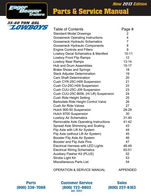
35-60 TON GSL<br />
<strong>Parts</strong><br />
(800) 338-7088<br />
New 2013 Edition<br />
<strong>Parts</strong> & <strong>Service</strong> <strong>Manual</strong><br />
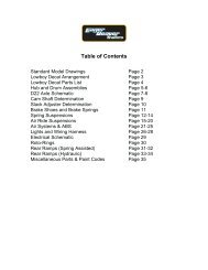
Table<br />
of<br />
Contents<br />
Customer <strong>Service</strong><br />
(800) 722-8803<br />
ext: 3251<br />
Page<br />
#<br />
Standard<br />
Model<br />
Drawings<br />
2<br />
Gooseneck Operating Instructions 4<br />
Gooseneck Hydraulic Schematics 7<br />
Gooseneck Hydraulic Components 8<br />
Engine<br />
Controls<br />
and<br />
Filters<br />
9<br />
Lowboy Decal Schematics & Manifest 10-11<br />
Lowboy<br />
Front<br />
Flip<br />
Ramps<br />
12<br />
Lowboy<br />
Rear<br />
Ramps<br />
13-14<br />
Hub and Drum Assemblies 15-17<br />
Brake<br />
Shoes<br />
and<br />
Springs<br />
18<br />
Slack Adjuster Determination 19<br />
Cam<br />
Shaft<br />
Determination<br />
20<br />
Cush CYR-25C-H09 Suspension 21<br />
Cush CU-25C-H09 Suspension 22<br />
Cush CUU-25C-J09 Suspension 23<br />
Cush CUU-25C-B09L (Hi Lift) Suspension 24<br />
Cush<br />
Ride<br />
Height<br />
Setting<br />
25<br />
Barksdale Ride Height Control Valve 26<br />
Cush<br />
Air<br />
Ride<br />
Valves<br />
27<br />
Hutch 900-50 Suspension 28-29<br />
Hutch<br />
9700<br />
Suspension<br />
30<br />
Lowboy<br />
Air<br />
Schematics<br />
31-40<br />
Removable Axle Operating Instructions 41-42<br />
Spread Axle Shimming and Scaling 43<br />
Flip Axle with Lift Air System 44<br />
Flip Axle (without Lift Air System) 45<br />
Booster Flip Axle Air System 46<br />
Booster<br />
and<br />
Flip<br />
Axle<br />
Pins<br />
47<br />
Electrical Harness with LED Lights 48-49<br />
Electrical Wiring Schematics 50-51<br />
Auxiliary Flasher Kit (PLUS) 52<br />
Strobe<br />
Light<br />
Kit<br />
53<br />
Miscellaneous<br />
<strong>Parts</strong><br />
List<br />
54<br />
OPERATION & SERVICE MANUAL APPENDED<br />
Sales<br />
(800) 257-8163
STANDARD MODEL DRAWINGS<br />
35GSL/BR<br />
35GSL-S<br />
35GSL-S4S<br />
35GSL-PT<br />
50GSL/PT<br />
Page 2
STANDARD MODEL DRAWINGS<br />
50GSL/3<br />
55GSL/3<br />
55GSL/BR<br />
Page 3<br />
60GSL/3<br />
60GSL/BR
GOOSENECK OPERATION<br />
35-60 GSL’s<br />
Page 4
GOOSENECK OPERATION<br />
35-60 GSL’s<br />
Page 5
GOOSENECK OPERATION<br />
35-60 GSL’s<br />
Page 6
Page 7
<strong>Eager</strong> <strong>Beaver</strong> <strong>Trailers</strong> GSL Hydraulic Components & Cylinder Pins<br />
Item<br />
Packing<br />
# Description Part # Kit PN Notes<br />
1 Stinger Cylinder - All GSL 2060898 2060804 Includes Clevis End<br />
1 Pin Set - Stinger Cylinder 2060965 N/A Cylinder Rod Clevis End, PN 2062296<br />
2 35-40 GSL Lift Cylinder After 1987 2060513 2059965 Pre 1987 requires bottom mounting tube trim<br />
2 35 & 50 GSL-PT Lift Cylinder after 8/2002 2062100 2062235 Pre 8/2002 had 12.5" Stroke. Replace in pairs w 11.5" stroke<br />
2 50 GSL Lift Cyl After July 1994 2062128 2060907 7" Bore x 9 " Stroke (2000-2006 check BOM for PT option)<br />
2 55 & 60 GSL Lift Cyl After July 1995 2062246 2062234 7.75" Bore x 9" Stroke<br />
2 55 & 60 GSL-PT Lift Cyl Begin Mar 2010 2060960 Sp. Order 55/60PT models only 7.75" Bore x 11.5" Stroke<br />
2 55-60 GSL 118+ Swing; 65-75GSL
<strong>Eager</strong> <strong>Beaver</strong> <strong>Trailers</strong><br />
Power Pack Keys, Switches, Controls, Hydraulics, & Filters<br />
Keys - Switch - Ignition Harness PN Notes<br />
Kohler Ignition Key Only 2059876 One Key - 14HP CH440 - Begin Oct 3, 2012 & 18HP CH620 *<br />
Kohler Ignition Switch & 2 Keys 2058207 Delphi style, 14HP CH440 - Begin Oct 3, 2012 & 18HP CH620 *<br />
Kohler Ignition Harness - 6' 2059202 Delphi ends, 14HP CH440 - Begin Oct 3, 2012 & 18HP CH620 *<br />
Kohler Ignition Key Only 2062001 1 Key - 14HP CH440 OHV Engine (May-Sep 2012)<br />
Kohler Ignition Switch & 2 Keys 17099 07-S Switch w/ 2 Keys - 14HP CH440 Engine (May-Sep 2012)<br />
Honda Ignition Key Only 2062001 One Key (fits both GCANK and GCBCT engines) (Also Kohler)<br />
Honda Ignition Switch (GCANK) 2062147 GX390UI until Mid Feb 2011 - Includes 2 Keys<br />
Honda Ignition Harness (GCANK) 2062150 72" Switch Extension Harness (between Switch and Engine)<br />
Honda Ignition Switch (GCBCT) 2062124 GX390UT2 with CDI Ignition begin Mid Feb 2011 - May 6, 2012<br />
Robins Ignition Key Only 2060892 Replacement Key Only<br />
Robins Ignition Switch 2060848 Includes Keys (Robins EY40, EH34 & EH41 Engines)<br />
Robins Ignition Switch Harness 2060897<br />
* Also Kohler Magnum M16 Flathead Engines (mid 1980's thru mid 1990's, GFG and GHG Model <strong>Trailers</strong>)<br />
Choke & Throttle Cables PN Notes<br />
Choke Cable 96" 2059149 All Lowboys with Powerpack (Except Hatz Diesel)<br />
Throttle Cable 84" Long 2059148 All Lowboys with Powerpack<br />
Choke Linkage Kit 2062149 Honda GX390 and Kohler CH440 Only<br />
Filters & Starter Motors PN Notes<br />
Air Filter - KOHLER 14HP CH440 17883 03-S1 Quad "Cyclone" Filter and pre-Filter<br />
Air Filter - KOHLER 18HP CH620 47083 03-S Pre-Filter PN 24083 02-S<br />
Air Filter - HONDA 2062145 Honda GX390UI and UT2 (both GCANK & GCBCT prefix)<br />
Air Filter - ROBINS EY40 2061022 Robins EY 40 Only (Round, Cone Shaped)<br />
Air Filter - ROBINS EH41 2062270 Robins EH 41 Only (5 Sided, not Cone Shaped)<br />
Starter Motor - HONDA 2062146 Honda GX390 up to SN GCANK 1414795 (2005 - 2007 only)<br />
Hydraulic Oil Filter (25 Micron) 2056554 All Lowboys with Powerpack<br />
Hydraulic Control Valve and Pump<br />
Component PN Notes<br />
3-Spool 4-Way Control Valve 2060823 Packing Kit Only PN 2060992<br />
Replacement Handle 2061080 Handle only, no knob<br />
Black Ball Knob for Handle End 2062189 Knob only, no handle<br />
Handle, Knob & Linkage Kit 2062266<br />
Hydraulic Pump 2059919 Prince SP-F26, 3000 PSI, 9/16" shaft<br />
Seal Kit 2062339 Seal Kit includes Shaft Seal<br />
Shaft Seal ONLY 2062289<br />
Lovejoy half 9/16" shaft 2062324 Hydraulic Pump shaft (All Pumps)<br />
Lovejoy half 1" shaft 2060478 Engine shaft - Kohler CH440, Honda, Robins, & Hatz Diesel<br />
Lovejoy half 1 1/8" shaft 2060477 Engine shaft - Kohler 18HP CH620 & Kohler M16<br />
Lovejoy Spider 2062325<br />
Pump-to-Engine Mounting Housing 2060267 Kohler CH440, Honda, Robins Subaru, & Hatz Diesel only<br />
Pump-to-Engine Mounting Housing 372011 Kohler 18HP CH620 & Kohler M16<br />
Pressure Relief Valve (Hyd Pump) 2060930 Combo WL/PP Units ONLY - Mounts on Hyd Pump<br />
Page 9
Page 10
<strong>Eager</strong> <strong>Beaver</strong> <strong>Trailers</strong> Lowboy Trailer Decals<br />
PART # QTY DESCRIPTION<br />
2059016 2 CHECK WHEEL LUGS DECAL<br />
2060618 2 ROTO-RING DECAL<br />
2062005 2 CAUTION CENTERLINE DECAL<br />
2060608 75 RED/WHITE CONSPICUITY STRIPING ("DOT STRIPING")<br />
2059181 2 "DO NOT SIDE LOAD" DECAL<br />
2062007 1 WEBB WHEEL TORQUE DECAL, 10 STUD, HUB PILOTED<br />
Or 2059165 / Spoke-Demountable ; 2056558 / 10-Stud, Stud Piloted<br />
2059162 2 RECOMMENDED TIRE PRESS DECAL<br />
2062332 2 EAGER BEAVER TRAILERS DECAL - MEDIUM * (6" High x 37" Long)<br />
2062208 1 USA HARNESS DECAL<br />
2062173 1 REPLACE DAMAGED WOOD DECAL<br />
2062129 6 OBLONG AMBER REFLECTIVE DECAL<br />
2062130 2 OBLONG RED REFLECTIVE DECAL<br />
With Detachable Hydraulic Gooseneck, Add the Following:<br />
2059329 1 "HAULING PIN" DECAL<br />
2059348 1 "HAULING PIN LEVER" DECAL<br />
2059585 1 WARNING HAULING PIN" DECAL<br />
2062009 9 "GREASE" FITTING DECAL<br />
2062010 1 PRE CENTRAL LUBE "LUBRICATION GUIDE" (Central Lube Use PN 445826)<br />
2062011 1 HAULING PIN "INTERLOCK WARNING" DECAL<br />
2062012 1 COMPRESSION BLOCK NUT TIGHTEN DECAL<br />
With ABS, Add the Following:<br />
2062003 1 CAUTION TRAILER EQUIPPED W/ABS BRAKES<br />
2061051 2 ABS DECAL(ALL WHEEL)<br />
2062004 1 ABS INDICATOR LAMP INSTRUCTIONS<br />
2062179 1 DANGER SPRING BRAKES<br />
2063521 KIT GSL WITH ABS DECAL KIT (Includes All Decals Listed Above)<br />
Add Trailer Model Decal (specify if "PT" or "BR" Model)<br />
2059281 2 DECAL "25GLB" WHITE (specify if 35, 50 or 60 GLB)<br />
2059275 2 DECAL "35GSL" WHITE<br />
2059277 2 DECAL "50GSL" WHITE<br />
2062244 2 DECAL "55GSL" WHITE<br />
2059278 2 DECAL "60GSL" WHITE<br />
With Cush Air Ride Suspension, Add the Following:<br />
2062245 1 CUSH SUSPENSION TORQUE<br />
2062143 1 AIRBAG EXHAUST OPERATION (use with toggle valves only)<br />
445863 1 AIRBAG EXHAUST OPERATION (use with Push-Pull valves only)<br />
With Pony Motor, Add the Following:<br />
2062249 1 NOTICE - FUEL SHUT OFF VALVE<br />
2062008 1 "HOT MUFFLER" DECAL<br />
With a Lift Axle (All 50 - 60 Ton <strong>Trailers</strong>), Add the Following:<br />
2062142 1 LIFT AXLE OPERATION (use with toggle valves only)<br />
445864 1 LIFT AXLE OPERATION (use with Push-Pull valves only)<br />
Optional Flasher Kit & <strong>Manual</strong> Raise & Lower Air Ride Suspension<br />
445870 1 FLASHER KIT OPERATION<br />
445865 1 MANUAL RAISE & LOWER (use with PUSH-PULL Valve only)<br />
* ECN 016 (3/15/2010): Large (2059370) & Small (2062020) EB Decals on Lowboys replaced with Medium, PN 2062332<br />
--For Goosenecks with Fenders use Small Decal PN 2062020--<br />
2062020 2 EAGER BEAVER TRAILERS DECAL - SMALL (4" High x 25" Long)<br />
2059370 2 EAGER BEAVER TRAILERS DECAL - LARGE (8" High x 58" Long)<br />
Page 11
GSL LOWBOY FRONT FLIP RAMPS<br />
(NO SPRING ASSIST)<br />
Item Description Part #<br />
1A Front Flip Ramp - Steel with Grouser Bars (Non-PT) 2060550<br />
1B Front Flip Ramp - Wood Filled (Non-PT) 2059196<br />
2 Front Flip Ramp - Wood Filled (PT Model Only) 2059198<br />
Not Shown Front Flip Ramp - Steel w Grouser Bars PT (7" H x 24" Long) (PT) 2059199<br />
Not Shown Front Flip Ramp - Steel w Grouser Bars PT (7" H x 36" Long) (PT) 994299<br />
3 Ramp Bar - 16" Long (2 per Ramp) - Standard Move Ramps 2063071<br />
3 Ramp Bar - 22" Long (1 per Ramp) - Max Move Ramps only 2054640<br />
4 Movable Linkage - 13" Long 2060500<br />
5 Flip Ramp Mounting Linkage - 9" High - Non PT Models Only 2061071<br />
Flip Ramp Mounting Linkage - 7" High - PT Models Only 2059201<br />
6 Split Pin 2059020<br />
Page 12
Lowboy Single Acting Rear Ramp Linkage - before September 2008<br />
Item # Part No Alt Part No Qty Unit Description<br />
1 993880 Order Items 1A & 1B Separately<br />
1A 143721 2060553 2 EA Tailboard Fixed Linkage 1/2 X 4-5/8 X 11-3/4<br />
1B 188205 2060866 1 EA Tailboard Hinge Pin 2" Dia. X 32"<br />
2 993881 2059403 1 AY BR Moveable Link Assy (Includes Items 2A, 2B, 2C, 2D)<br />
2A 143732 2 EA Tailboard Movable Link 3/4 X 8.5X 11.125<br />
2B 218010 1 EA 2" SCH 40 X 18-3/8 SEAMLESS PIPE<br />
2C 143731 1 EA Bar Link 1/2 X 4-1/2 X 8<br />
2D 168089 2 EA Tailboard Link Spring Stop 1/2 X 2X 1.75<br />
3 991822 2054640 1 EA 1.5" Dia. x 22" Dia Ramp Bar Assy<br />
4 402001 2059240 1 EA Heavy Duty Double Spring<br />
5 411601 2059020 1 EA Roll Pin - 5/16" Dia x 2.5" Long<br />
Note: Item # 1 not available pre-assembled. Order 1A & 1B separately, as needed<br />
Items # 1A & 1B require assembly at time of installation to trailer tailboard<br />
Items # 3, 4, 5 and Ramps not included in any assembly<br />
Item # 2 available as assembly under PN 2059403<br />
Page 13
Item # Part No Alt Part No Description<br />
1 991877 2" Dia x 36.5" Ramp Bar<br />
2 991876 2063220 1.5" Dia x 25" Ramp Bar<br />
3 411601 2059020 5/16" Dia x 2.5" Roll Pin<br />
4 173642 Tailboard Fixed Linkage<br />
5 178509 1/2" x 3/4" x 17.5" Long Spring Stop<br />
6 991863 Rotating Linkage<br />
7 402021 2062327 Off-Ground Lift Spring (1 per Ramp)<br />
8 402007 2062134 Off-<strong>Beaver</strong>tail Lift Spring (3 per Ramp)<br />
Page 14
10 Stud Hub (11.25" BC) Uni-Mount (Hub Piloted)<br />
16 ½" x 7" Outboard Drum with Webb 2023 Series Hub<br />
(Standard Equipment 35-75 Ton Lowboys since 2000)<br />
Item Nomenclature P/N Remarks<br />
1 Hub 2062290 Webb 2023 (Includes cups & studs)<br />
2 Drum 2062291 Webb 66864F<br />
3 Inner Bearing Cup 2058307<br />
4 Outer Bearing Cup 2058306<br />
5 Inner Bearing 2058309<br />
6 Outer Bearing 2058308<br />
7 Oil Seal 2055828<br />
8 Studs 2061085<br />
9 Flange Nuts 2061086<br />
10 Oil Cap w/ plug 2055089 Cap, includes window & plug<br />
11 Gasket - oil cap 2055090<br />
12 Oil cap window kit 2058056 Window, gasket & plug<br />
13 vent plug 2055749<br />
14 Lock Washer Procure locally<br />
15 Machine screw 5/16 - 18 thread x 3/4" long<br />
16 Inner Spindle Nut 2055836<br />
17 Spindle Lock Nut 2058268<br />
18 Star Washer 2058267<br />
19 Outer Spindle Nut 2059229<br />
Wheel, Steel 2060825 8.25 X 22.5, 10 Stud Hub piloted<br />
Axle Beam, 77" Trk 332101 Includes, brakes, camshaft, slack adjusters<br />
Page 15
10 Stud Hub (11.25" BC) Ball Seat Mount (Stud Piloted)<br />
16 ½" x 7" Outboard Drum with Webb 2023 Series Hub<br />
(Standard Equipment 35-60 Ton Lowboys 1997-2000)<br />
Item<br />
Nomenclature<br />
P/<br />
N Remarks<br />
1a Hub LH w Studs & Cups (no nuts) Special Order Webb 20235-ML #<br />
1b Hub RH w Studs & Cups (no nuts) Special Order Webb 20235-MR #<br />
2 Drum<br />
2062291<br />
Webb<br />
66864F<br />
3 Inner<br />
Bearing<br />
Cup<br />
2058307<br />
HM218210<br />
4 Outer Bearing Cup 2058306 HM212011<br />
5 Inner<br />
Bearing<br />
2058309<br />
HM218248<br />
6 Outer<br />
Bearing<br />
2058308<br />
HM212049<br />
7 Oil<br />
Seal<br />
2055828<br />
8a Stud, LH (Left Tighten) Special Order Webb 101173<br />
8b Stud, RH (Right Tighten) Special Order Webb 101172<br />
9a Inner Cap Nut - LH 2055701<br />
9b Inner Cap Nut - RH 2055538<br />
10a Outer Cap Nut - LH 2060878<br />
10b Outer Cap Nut - RH 2060879<br />
11<br />
Gasket<br />
- oil<br />
cap<br />
2055090<br />
12 Oil Cap (complete) 2055089 Cap, includes window & plug<br />
13<br />
Oil<br />
cap<br />
window<br />
kit<br />
2058056<br />
Window,<br />
screws,<br />
gasket<br />
& plug<br />
14 Oil Cap Rubber Plug 2055749 Included with Window Kit<br />
15 Machine screw & Lock Washer Procure Locally 5/16 - 18 thread x 3/4" long<br />
16<br />
Inner<br />
Spindle<br />
Nut<br />
2055836<br />
17<br />
Spindle<br />
Lock<br />
Nut<br />
2058268<br />
18<br />
Star<br />
Washer<br />
2058267<br />
19<br />
Outer<br />
Spindle<br />
Nut<br />
2059229<br />
Rim, 10 Stud 8.25 x 22.5 341018 Special Order<br />
# LH Hub with LH Studs go on Left Hand (Street Side) of Trailer<br />
# RH Hub with RH Studs go on Righ Hand (Curb Side) of Trailer<br />
Page 16
Lowboy - 35 Ton & Larger - Webb Spoke Type (Open Center)<br />
Item Nomenclature P/N Remarks<br />
1 Studs 2055084<br />
2 Outer Bearing Cup 2058306<br />
3 Rim Clamp 2058317<br />
4 Rim Nut 2055085<br />
5 Machine screw Procure locally - 5/16-18 x 3/4 Grade 5<br />
6 Lock<br />
Washer<br />
Procure<br />
locally<br />
- 5/<br />
16-18<br />
( fine<br />
thread)<br />
7 Oil Cap w/ plug 2055089 Cap, includes window & plug<br />
8 Gasket - oil cap 2055090<br />
9 Spacer 2058316<br />
10<br />
Nut<br />
3/<br />
4"<br />
x 10<br />
( incl<br />
with<br />
Dayton<br />
Kit<br />
13-6583)<br />
11<br />
Washer<br />
Included<br />
with<br />
Dayton<br />
Kit<br />
13-6583<br />
12 Hub 2060453 Webb 7520 - Includes Studs & Cups<br />
13 Inner Bearing Cup 2058307<br />
14 Drum 2058313 Webb 67518<br />
15<br />
Capscrew<br />
3/<br />
4"<br />
x 10<br />
x 2"<br />
( incl<br />
with<br />
Da<br />
16 Oil cap window kit 2058056 Window, gaskets, & plug<br />
17 Vent plug 2055749<br />
18 Oil Seal 2055828<br />
19 Inner Bearing 2058309<br />
20 Outer Bearing 2058308<br />
21 Inner Spindle Nut 2055836<br />
22 Spindle Lock Nut 2058268<br />
23 Star Washer 2058267 Not Shown in Diagram<br />
24 Outer Spindle Nut 2059229<br />
Page 17<br />
yton<br />
Kit<br />
13-6583)
<strong>Eager</strong> <strong>Beaver</strong> <strong>Trailers</strong> - Lowboy Air Brake Shoes<br />
All 35-75 Ton Lowboys (16 1/2" x 7" Drums) (See Below 35 Ton Exceptions * )<br />
Shoe (each, need 2 per wheel) 2060915<br />
Brake Repair Kit (per wheel) 2059157<br />
Seal (per wheel) 2055828<br />
35 & 40 Ton* - Pre 1998 (12 1/4" X 7 1/2" Drums) Upto '93 (P) 94-'96 (PQ) After '97 (Spicer)<br />
Shoe (each) 2055842 2060853 2060455<br />
Brake Repair Kit 2058058 2060900 2060956<br />
Seal (per wheel) 2055828 2055828 2055828<br />
P Style PQ Style Spicer Style<br />
Both Ends Closed One End Closed Both Ends Open<br />
* After 1998 most 35 Tons have 16 1/2" x 7" Drums. Prior to 2002, always have customer verify drum size.<br />
Below are some general guidelines. However, customer verification still required.<br />
- Prior to 1988 all 35 Ton and 3 Axle 40 Tons should have 12 1/4" x 7 1/2" Drums<br />
- Between 1988 & 1998, only 35 Ton BR models should have 12 1/4" x 7 1/2" Drums<br />
- Beginning in 1988 Straight Back (or -S) 35 Ton and 3 Axle 40 Ton models should have 16 1/2" x 7" Drums<br />
- After 1998, with the exception of Model 35GSL-S4S, all 35 Tons had 16 1/2" x 7 " Drums<br />
- Between 1998 and 2002, 12 1/4" x 7 /1/2" Drums were still used on Model 35GSL-S4S<br />
After 2002, All 35 Tons regardless of model or configuration should have 16 1/2" x 7" Drums<br />
Page 18
When ordering Slack Adjusters, please provide the following information:<br />
1. Whether Automatic or <strong>Manual</strong><br />
2. Whether adjuster arm (which attaches to air brake chamber) is Straight or Curved<br />
3. Whether it has 10 or 28 Splines<br />
4. Manufacturer name and any part numbers from old slack adjuster<br />
Circle Applicable Feature on Below Matrix<br />
Slack Adjuster<br />
EB Part # Application<br />
10 Spline 2060873 C.B. 10-12 Ton **<br />
Straight 2062263 Spicer, Haldex 20-25 Ton (pre-'97) *<br />
28 Spline 2060934 C.B. 10-12 Ton **<br />
Automatic 2060971<br />
Spicer, Haldex 35-60 Ton *<br />
Begin Oct 1994 451154 C.B., Lowboys Only Begin 7/2009<br />
Curved<br />
Straight 10 Spline 2058077<br />
<strong>Manual</strong><br />
Before Oct 1994 Curved 10 Spline 2059480<br />
10 Spline 2060755 Spicer, Haldex 20-25 Ton (older) *<br />
28 Spline 2061083 Spicer, Haldex 20-25 Ton *<br />
* Spicer Automatic Slack Adjuster Bracket 2061084 Not included with Slack<br />
** 10K axles - attach Brake Chamber Clevis to 5" Hole in Slack; 12K uses 6" Hole in Slack<br />
Original Slack Manufacturer:<br />
OEM Part Number on Original Slack<br />
Fax your order to <strong>Eager</strong> <strong>Beaver</strong> Trailer <strong>Parts</strong>: 856-423-0999<br />
Your Name:<br />
Your Voice Telephone:<br />
<strong>Eager</strong> <strong>Beaver</strong> <strong>Trailers</strong><br />
Slack Adjuster Determination & Ordering Worksheet<br />
<strong>Eager</strong> <strong>Beaver</strong> <strong>Trailers</strong> - 548 Swedesboro Ave, Mickleton, NJ 08056<br />
Telephone 800-338-7088; FAX 856-423-0999<br />
Page 19
Cam Shaft Determination & Ordering Worksheet<br />
Step 1 Decide whether the cam is a LEFT or a RIGHT hand and whether it<br />
is a SMALL (3 3/32”) or LARGE (4 ¼”) head.<br />
Step 2 Measure the length of the cam. It is best to provide both the<br />
dimensions “A”, the distance from head to snap ring groove, and<br />
dimension “B”, the distance from the head to the end of the cam.<br />
Step 3 Measure the diameter of the cam at both “C”, just behind the head,<br />
and “D” just inside the spline.<br />
Step 4 Finally, determine whether the cam is a 10 spline or 28 tooth spline.<br />
Please fill in the chart below when ordering a cam shaft<br />
HEAD STYLE<br />
LEFT HAND SMALL<br />
RIGHT HAND SMALL<br />
LEFT HAND LARGE<br />
RIGHT HAND LARGE<br />
DIMENSION SPLINE<br />
“ A”<br />
10<br />
“ B”<br />
28<br />
“C”<br />
“D”<br />
Fax the completed worksheet to <strong>Eager</strong> <strong>Beaver</strong> <strong>Trailers</strong> @ 856-423-0999.<br />
Your Name: .<br />
Your Voice Tel #: .<br />
Page 20
CUSH CYR-25C-H09<br />
ITEM DESCRIPTION PART #<br />
2a Steel Sleeve (6.2" OD) & Bushing 2062280<br />
2b Wear Washer 2062282<br />
2c E-20 Torx Bolt 0.875"- 9 UNC x 12" 2062286<br />
2d SecureLoc Nut 0.875"- 9 UNC incl. with Bolt<br />
2e Spacer Collar - Double Step 2062284<br />
2f Washer 0.875" SAE ID 2062030<br />
3 Frame Sleeve, 7"OD x 6.25" ID (Weld In) T0032 *<br />
4a Alignment Gear, eccentric, outer 2062031<br />
4b Alignment washer, inner 2062032<br />
6 Susp. Air Spring (1 per swing arm) 2061077<br />
8a Shock Absorber 2060490<br />
8b Bolt 0.75" - 10UNC x 3.25" GR 5 2062035<br />
8c Nut, lock, 0.75" - 10UNC 2062037<br />
9 Chain Kit, 14 Link with Clevis Ends 2062034<br />
* Special Order<br />
Page 21
CUSH CU-25C-H09<br />
ITEM DESCRIPTION PART #<br />
3a Bushing Only 2062281<br />
3b Wear Washer 2062282<br />
3c Washer 0.875" SAE ID 2062030<br />
3d E-20 Torx Bolt 0.875"- 9 UNC x 10" 2062285<br />
3e SecureLoc Nut 0.875"- 9 UNC incl. with Bolt<br />
3f Reducer, 1.25" OD to 0.9" ID 2062029<br />
4a Alignment Gear, eccentric, outer 2062031<br />
4b Alignment washer, inner 2062032<br />
5a Shock Absorber 2062170<br />
5b Bolt 0.75" - 10UNC x 3.25" GR 5 2062035<br />
5c Bolt 0.75" - 10UNC x 9.5" GR 5 2062036<br />
5d Nut, lock, 0.75" - 10UNC 2062037<br />
5e Washer 3/4" ID 2062038<br />
6 Chain Kit, 7 Link with Clevis Ends 2062033<br />
8 Susp. Air Spring (1 per swing arm) 2061077<br />
Page 22
CUSH CUU-25C-J09L (Hi Lift)<br />
ITEM<br />
DESCRIPTION<br />
PART<br />
#<br />
3a<br />
Bushing<br />
Only<br />
2062281<br />
3b<br />
Wear<br />
Washer<br />
2062282<br />
3c<br />
Washer<br />
0.<br />
875"<br />
SAE<br />
ID<br />
2062030<br />
3d E-20 Torx Bolt 0.875"- 9 UNC x 10" 2062285<br />
3e SecureLoc Nut 0.875"- 9 UNC incl. with Bolt<br />
3f Reducer, 1.25" OD to 0.9" ID 2062029<br />
4a Alignment Gear, eccentric, outer 2062031<br />
4b Alignment washer, inner 2062032<br />
5a<br />
Shock<br />
Absorber<br />
2062170<br />
5b Bolt 0.75" - 10UNC x 3.25" GR 5 2062035<br />
5c Bolt 0.75" - 10UNC x 9.5" GR 5 2062036<br />
5d<br />
Nut,<br />
lock,<br />
0.<br />
75"<br />
- 10UNC<br />
2062037<br />
5e<br />
Washer<br />
3/<br />
4"<br />
ID<br />
2062038<br />
6 Chain Kit, 7 Link with Clevis Ends 2062033<br />
7 Lift Air Spring (1 per swing arm) 2062186<br />
8 Susp. Air Spring (1 per swing arm) 2061077<br />
Page 23
CUSH CUU-25C-B09L (Hi Lift)<br />
ITEM DESCRIPTION PART #<br />
3a Bushing Only 2062281<br />
3b Wear Washer 2062282<br />
3c Washer 0.875" SAE ID 2062030<br />
3d E-20 Torx Bolt 0.875"- 9 UNC x 10" 2062285<br />
3e SecureLoc Nut 0.875"- 9 UNC incl. with Bolt<br />
3f Reducer, 1.25" OD to 0.9" ID 2062029<br />
4a Alignment Gear, eccentric, outer 2062031<br />
4b Alignment washer, inner 2062032<br />
5a Shock Absorber 2062170<br />
5b Bolt 0.75" - 10UNC x 3.25" GR 5 2062035<br />
5c Bolt 0.75" - 10UNC x 9.5" GR 5 2062036<br />
5d Nut, lock, 0.75" - 10UNC 2062037<br />
5e Washer 3/4" ID 2062038<br />
6 Chain Kit, 7 Link with Clevis Ends 2062033<br />
7 Lift Air Spring (1 per swing arm) 2062186<br />
8 Susp. Air Spring (1 per swing arm) 2061077<br />
Page 24
Page 25
1 /4-20<br />
Mounting<br />
Studs<br />
Suspension<br />
Port C2<br />
(Plug, If<br />
Necessary)<br />
BARKSDALE RIDE HEIGHT CONTROL VALVE<br />
INSTALLATION and ADJUSTMENT PROCEDURES<br />
Figure 1. The Barksdale non-delay height control valve<br />
Supply Port<br />
Exhaust Port<br />
Part Number<br />
Supply Port<br />
Alignment Hole<br />
Exhaust Tube Exhaust Fitting<br />
Suspension<br />
Port C2 (Plug,<br />
If Necessary)<br />
Exhaust Port<br />
C2<br />
FITTING INSTALLATION<br />
1. Apply thread sealant onto the tting threads, unless<br />
it is already pre-applied.<br />
IMPORTANT: DO NOT APPLY TAPE to the tting threads;<br />
the tape may cause contamination of the<br />
air system.<br />
2. Install the supply and suspension ttings on the<br />
height control valve.<br />
C1<br />
Suspension Port C1<br />
Suspension Port C1<br />
Raise<br />
Lower<br />
Figure 2. Ride height adjustment<br />
Fill<br />
Position<br />
Control<br />
Arm<br />
Neutral<br />
Position<br />
Exhaust<br />
Position<br />
Page 26<br />
IMPORTANT: DO NOT OVERTIGHTEN ttings onto the<br />
height control valve. Overtightening the<br />
ttings may damage the valve body.<br />
VALVE MOUNTING/AIR LINE ATTACHMENT<br />
IMPORTANT: Before installing the height control valve,<br />
please review the drawings in the height<br />
control valve kit in order to determine the<br />
proper mounting and assembly.<br />
1. When tightening the lock nuts on the height control<br />
valve mounting studs, DO NOT BACK OUT the<br />
studs from the height control valve body.<br />
IMPORTANT: Loosening the studs may cause the height<br />
control valve to leak.<br />
2. Ports C1 and C2 on the forward and rear face of<br />
the height control valve are the suspension ports.<br />
Attach the air line(s) from the air springs to the C1<br />
and/or C2 port(s) (Figure 1).<br />
3. When using only one suspension port, plug the<br />
unused port with the 1 /4-inch NPT pipe plug<br />
provided in the height control valve kit.<br />
4. Attach air supply line from the pressure protection<br />
valve to the supply port on the top of the height<br />
control valve (Figure 1).<br />
5. Install the exhaust tting into the exhaust port<br />
(Figure 1).<br />
6. Tighten all the lines.<br />
RIDE HEIGHT ADJUSTMENT<br />
1. Determine recommended ride height by locating<br />
and reading the information on the identication<br />
tag; it is on the suspension trailing arm.<br />
2. If necessary, rotate the control arm for the height<br />
control valve up to raise or down to lower the axle<br />
until the distance between the suspension<br />
mounting surface and the axle center matches the<br />
recommended suspension ride height (Figure 2).<br />
IMPORTANT: After setting the ride height, the control<br />
arm must remain in the neutral position.<br />
3. Insert the wooden centering dowel into the control<br />
arm alignment hole and engage into the housing<br />
(Figure 1).
Page 27
Page 28
HUTCH 900-50 SUSPENSION PARTS LIST<br />
Item Hutch PN<br />
<strong>Eager</strong><br />
<strong>Beaver</strong><br />
Stocked<br />
PNs<br />
Qty<br />
Used Description<br />
1 10476-03 2 Trunnion Hanger, 4-1/2"<br />
2 10376-00 2058106 4 Hex Bolt 3/4" -16 UNF x 4 1/2" GR5<br />
3 895-00 2058105 2 Washer, 7GA x 4 1/32 ID x 5 3/4 OD<br />
4 893-10 1 Trunnion Tube (42" S.C.) 26-1/8" Ig<br />
5 835-04 2058100 4 U-Bolt, Trunnion, 15-3/8"<br />
7 10055-00 2058103 2 Spring, 7 Leaf (50,000 Ibs.)<br />
8 9941-02 2058090 4 Spring End Cap<br />
9 841-00 4 Hex Nut, Self Locking 3/4" - 16 UNF<br />
10 9293-00 8 Hex Bolt, 5/8" -18 UNF x 2" GR5<br />
12 814-00 2058091 8 Rubber Pad - Plain 814-00<br />
13 10608-00 4 Adjustment Plate<br />
14 9938-00 2058092 4 Spring Seat<br />
15 10273-00 8 Washer, 1/8" x 21/32 ID x 1 15/16 0D<br />
16 11513-03 8 Hex Lockrrut 5/8" - 18 UNF<br />
17 10064-02 2058093 8 U-Bolt - Axle, 10-1/2" 10064-02<br />
18 12919-01 2 Galvanized Liner - .040 x 4.75 x 10.00<br />
19 891-00 2 Trunnion Hub - Upper Half<br />
20 890-00 2058104 2 Rubber Bushing, Trunnion Hub<br />
21 892-00 2058099 2 Trunnion Hub - Lower Half<br />
22 837-00 8 Washer, 1/8" x 1 1/4 ID x 2 1/4 OD<br />
23 836-00 2058101 8 Hex Nut, 1 1/8" -12 UNF x 1 1/2 HI<br />
24 10562-00 2060165 16 Flange Nut Self Locking 1-14 UNS 10562-00<br />
25 820-00 2058097 2 Spring Clamp Plate<br />
Page 29
Page 30
Page 31
Lowboy Tri-Axle Air System with ABS, Dump Valve and Lift Axle<br />
Item Part Qty Description Comment<br />
1 322071 1 CUSH LWBY HT CONTROL VALVE KIT<br />
2 322129 1 PRESS REG VALVE,FIXED @ 70 PSI<br />
3 322132 2 TOGGLE CTRL VLV SEALCO#21600-2<br />
4 322133 2 AIR PILOT VLV - SEALCO #110591<br />
5 322135 1 QUICK REL VLV P/N 3800<br />
6 322139 1 BRAKE PROTECT VALVE #140270<br />
7 371503 1 3/8FNPT AIR/QD COUPLER<br />
8 371504 1 3/8FNPT AIR/QD NIPPLE<br />
9 381031 4 3/8T-3/8M STRAIGHT CONN (QCAB)<br />
10 381032 6 3/8T-1/4M STRAIGHT CONN (QCAB)<br />
11 381041 6 3/8TUBE UNION TEE (QCAB)<br />
12 381051 3 3/8T-3/8M SWVL BRNCH TEE(QCAB)<br />
13 381052 1 3/8T-1/8M SWVL BRNCH TEE(QCAB)<br />
14 381053 1 3/8T-1/4M SWVL BRNCH TEE(QCAB)<br />
15 381101 2 3/8FPT3/8FPT BLKHD CUP (STEEL)<br />
16 381153 2 3/4"HD NIPPLE,SEALCO #6006<br />
17 381203 2 AIR TANK (2850)-CUSH, 2PORT<br />
18 381211 2 REMOTE DRAIN VLV (350002-048)<br />
19 381302 2 SPRING BRAKE VLV,SEALCO 110800<br />
20 381878 60 3/8OD NYLON BRAKE TUBING- RED<br />
21 381879 45 3/8OD NYLON BRAKE TUBING-BLUE<br />
22 381880 30 3/8OD NYLON BRAKE TUBING-GREEN<br />
23 381881 10 3/8OD NYLON TUBING (BLACK)<br />
24 381901 6 24" 3/8 AIR BRAKE HOSE ASSY<br />
25 381902 4 30" 3/8 AIR BRAKE HOSE ASSY<br />
26 381904 2 48" 3/8 AIR BRAKE HOSE ASSY<br />
27 381910 2 54" 3/8 AIR BRAKE HOSE ASSY<br />
28 382001 5 3/8T-1/4M SWVL 90 ELBOW (QCAB)<br />
29 382002 10 3/8T-3/8M SWVL 90 ELBOW (QCAB)<br />
30 382003 3 3/8T-1/8M SWVL 90 ELBOW (QCAB)<br />
31 382106 10 3/8 90°STRT ELBOW,BRASS,3400X6<br />
32 382150 1 3/8"HEX NIPPLE (BRASS)<br />
33 382151 2 1/4"HEX NIPPLE (BRASS)<br />
34 382154 2 3/8"X 1/4"HEX NIPPLE (BRASS)<br />
35 382156 2 1/2"X 3/4"HEX NIPPLE<br />
36 382162 8 3/8 SQHD PLUG (BRASS)<br />
37 382163 2 3/4 HEXHD PLUG (BRASS)<br />
38 382165 2 1/8 HEX SOCKET PLUG (BRASS)<br />
39 382171 1 1/4 HEX SOCKET PLUG (BRASS)<br />
40 382224 1 MOUNTED TEE'S (SEALCO)<br />
41 383121 1 1/4 NPT BRASS TEE,W/H 3700X4<br />
42 391311 1 ABS 2.5" AMBR MARKERLITE (Not Shown)<br />
43 411101 2 1/4-20X2 ZN HXHD CPSCRW GR5<br />
44 411121 8 3/8-16X1.25 HEXHD CPSCRW GR5<br />
45 411301 2 1/4-20 NYLOCK<br />
Page 32<br />
28
Lowboy Tri-Axle Air System with ABS, Dump Valve and Lift Axle<br />
Item Part Qty Description Comment<br />
46 411309 2 5/16-18 HEXNUT ZN GR.2<br />
47 411321 8 3/8-16 NYLOC LOCKNUT<br />
48 411402 2 3/8 RBC CLAMP (Not Shown)<br />
49 411471 2 1"SAE FLAT WASHER PLATED<br />
50 411501 16 3/8 STD FLAT WASHER,ZN<br />
51 411503 4 1/4"U.S.STD.FLAT WASHER,ZN<br />
52 411553 10 24" TIE WRAP #CT24HD (Not Shown)<br />
53 411626 10 10-32X3/4 PANHD SCRW TYPE F ST<br />
54 411821 18 1/2ID HOSE SEPARATOR (Not Shown)<br />
55 413002 2 5/16-20X2 1/2 TORXHD DECKSCREW<br />
56 413041 1 1/4X1.375" SAFETY SNAP PIN<br />
57 420001 2 AIRTANK MOUNTING PAD #1068<br />
58 423002 1 2.5"GROMMET PET#B142-18 (Not Shown)<br />
59 440041 1 "CAUTION TRLR EQPT W/ABS BRKS" (Not Shown)<br />
60 440042 2 "ALL-WHEEL ABS"6.125X12.125 (Not Shown)<br />
61 440043 1 "ABS INDICATOR LAMP INSTRUCTN" (Not Shown)<br />
62 445844 1 DECAL (LIFT AXLE) (Not Shown)<br />
63 445845 1 DECAL (AIRBAG EXHAUST) (Not Shown)<br />
64 445850 1 DECAL -DANGER,SPRING BRAKES (Not Shown)<br />
65 451007 1 4005001030 (2&3 AXLE ECU),ESII<br />
66 451010 1 472-195-033-0 RELAY VALVE<br />
67 451022 6 4497130180 6' SENSOR EXT CBLE (Not Shown)<br />
68 451056 1 4494410300 10' RELAY CABLE,ESII (Not Shown)<br />
69 451020 4 4410328080 SENSOR W 1' CABLE (Not Shown)<br />
70 451015 4 8997598154 SENSOR RETAINER CLIP (Not Shown)<br />
Page 33
Page 34
Page 35
Tri-Axle Lowboy Air System with Push/Pull Valves ( NO Pilot Valves) and <strong>Manual</strong> Raise & Lower<br />
BU2 BU1<br />
3 1<br />
2<br />
2 4<br />
3 1 5<br />
Controls <strong>Manual</strong> Raise & Lower Valve<br />
for 3rd Axle Lift<br />
Page 36<br />
<strong>Manual</strong> Raise and Lower Valve<br />
Air Gauge<br />
from HCV<br />
from <strong>Manual</strong> Raise & Lower Vlave<br />
Controls <strong>Manual</strong> Raise & Lower Valve<br />
to ALL Main Air Bags<br />
to Non-Lift Axle Main Air Bags<br />
1st & 2nd Axle Dump Valve (p/n 322130)<br />
3 1<br />
2<br />
DUMP VALVE (3) Port x (2) Position - Knob IN<br />
PORT No Description<br />
1 HCV<br />
Air Flows from HCV to Air<br />
Connected<br />
2 Air Bags<br />
Bags<br />
3 Exhaust Blocked<br />
3 1<br />
2<br />
to Lift Axle Lift Bag<br />
to Lift Axle Main Air Bags<br />
for 3rd Axle Lift<br />
Exhaust Breather<br />
PUSHED IN<br />
2 4<br />
3 1 5<br />
DUMP VALVE (3) Port x (2) Position - Knob OUT<br />
PORT No Description<br />
1 HCV Blocked<br />
2 Air Bags<br />
Air Flows from Air Bags out<br />
Connected<br />
3 Exhaust<br />
of Exhaust<br />
3 1<br />
2<br />
from Dump Valve<br />
PULLED OUT<br />
70 psi Regulator<br />
Supply from Tank<br />
<strong>Manual</strong> Raise and Lower Valve<br />
Air Gauge<br />
3rd Axle Lift/Dump Valve (p/n 322128)<br />
LIFT VALVE (5) Port x (2) Position - Knob IN<br />
PORT No Description<br />
3 Dump Valve<br />
Air Flows from Dump Valve<br />
Connected<br />
2 4<br />
2 Air Bags<br />
to 3rd Axle Air Bags<br />
1 Exhaust<br />
Connected Lift Air Bags is Exhausted<br />
4 Lift Bag<br />
3 1 5<br />
5 Supply Blocked<br />
PUSHED IN<br />
LIFT VALVE (5) Port x (2) Position - Knob OUT<br />
PORT No Description<br />
2 4<br />
3 Dump Valve Blocked<br />
2 Air Bags<br />
3rd Axle Air Bags are<br />
Connected<br />
3 1 5<br />
1 Exhaust<br />
Exhausted<br />
PULLED OUT<br />
4 Lift Bag<br />
Air Flows from Supply to Lift<br />
Connected<br />
5 Supply<br />
Air Bag<br />
30<br />
10 20<br />
40 50 60 70 80<br />
90 100
Page 37
Page 38
Page 39
Page 40
REMOVABLE AXLE OPERATING INSTRUCTIONS<br />
Removable Axle ONLY Install<br />
When the Removable Axle is close coupled to the trailer, simply connect the bottom and top<br />
pins, bottom pins first. If equipped, u se the <strong>Manual</strong> over ride controls on the Removable Axle<br />
to raise or lower the Removable Axle until the upper pins can be inserted.<br />
Attach ALL air and electrical connections. See the final Check List at the end of this document<br />
for removable axle operational notes.<br />
WARNING! Make sure that the manual over ride control are turned OFF before<br />
moving trailer. To turn off the manual override control, push in the knob labeled PULL TO<br />
TURN ON MANUAL OVERRIDE. See label to right.<br />
Removable Axle and Nitro-Booster Install<br />
When the Removable Axle is used with a Nitro-Spreader Bar, simply connect the bottom and<br />
top pins of both the spreader bar and the Removable Axle, bottom pins first. Using the manual<br />
raise and lower controls for both the trailer and Removable Axle, as well the jack on the Nitro-<br />
Spreader bar can facilitate this connecting procedure. See the operational instruction decal on<br />
the Nitro-Spreader Bar for detail instructions of its use.<br />
WARNING! The Nitro-Spreader bar is for use with ONE Removable Axle ONLY. Using<br />
more than one Removable Axle can damage the Nitro-Spreader bar.<br />
WARNING! Make sure that the manual over ride controls on the trailer and Removable<br />
Axle are turned OFF before moving trailer.<br />
Removable Axle and East Coast Spreader Install<br />
When the Removable Axle is used with an East Coast Spreader Bar, a shimming process is<br />
required to transfer the proper weight to the Removable Axle.<br />
Install the bottom pins only of both the spreader bar and the Removable Axle. DO NOT install<br />
the top pins. Connect SUPPLY RED air line. This will allow the use of the Removable Axle’s<br />
manual override controls to raise and lower the Removable Axle. Install equal amounts of<br />
Shims at the spreader to trailer connection as are used at the Removable Axle to spreader<br />
connection. Make sure that the shims on each side of the trailer are always the same. Use the<br />
<strong>Manual</strong> Override controls on both the trailer and Removable Axle to raise or lower the trailer<br />
rear and the Removable Axle until the proper amount of shims can be inserted. This is usually<br />
achieved by raising the trailer rear and lowering the Removable Axle.<br />
Page 41
Changing the shim thickness may need to be done several times until ALL the axle loads are<br />
equal. Checking axle loads requires a certified scale.<br />
CAUTION! Confirmation of axle loads should only be checked at Certified Scales.<br />
Unequal axle loads can damage the trailer frame or suspensions.<br />
WARNING! Make sure that the any manual over ride control are turned OFF before<br />
moving trailer.<br />
Removable Axle Operation Check List<br />
• Make sure that the electrical plugs are firmly inserted and locked into the electrical<br />
socket at the rear of the trailer and spreader bar, if installed. Check ALL Lights for<br />
proper operation (Stop/Tail/Turn, Marker, Clearance and Strobe or Back-Up Lights (if<br />
equipped)).<br />
• Make sure that all Air Lines are connected at both the rear of the trailer and spreader<br />
bar, if installed. Check that the Air Brake will apply and release. Removable Axles do<br />
NOT have the ABS function. The brake application is independent of the trailer brakes<br />
and receives it supply (Emergency Line) and control (<strong>Service</strong> Line) directly from the<br />
tractor. See chart below for air connection labeling.<br />
Decal Image<br />
RED SUPPLY (Emergency) air line from tractor.<br />
BLUE Control (<strong>Service</strong>) air line from tractor.<br />
Supply line from trailer tank brake protection valve.<br />
Air Ride Supply air from trailer Automatic Height Control Valve.<br />
• The air suspensions air supply comes from the trailers Automatic Height Control Valve<br />
(HCV), so the ride height should be the same as the trailers axles when loaded. The<br />
Removable Axle should NOT be used when traveling empty or minimal load. The<br />
Removable Axle can be complete removed or flipped over onto the trailer for storage.<br />
WARNING! Make sure that the manual over ride control are turned OFF and<br />
back to automatic before moving the trailer. Failure to do so may damage either the<br />
trailer frame or suspensions.<br />
Page 42
Universal Spread Axle Shimming and Trailer Scaling Recommendations<br />
1. With a load on the trailer, scale 3 trailer axles. To do this, either remove the spreader or remove all shims and dump<br />
spread axle air to ensure negligible weight distributed to spread axle. Record the scale weight of the three trailer axles.<br />
Goal will be to distribute 25% of this weight to spread axle. For example, if 3 axles scale at 78,000 lbs, goal will be to<br />
distribute 19,500 lbs to the spread axle, thereby reducing the weight on the 3 trailer axles from 78,000 to 58,500.<br />
Page 43<br />
2. With a load on the trailer, add or remove shims as necessary between trailer & spreader and between spreader & the<br />
+1 spread axle to make top of trunnion beam over trailer axle almost level with top of beam on spread axle (see<br />
Reference Point A & B, respectively, in above diagram). Use the manual raise - lower valve on both trailer (if installed)<br />
and spread axle as a tool to raise & lower rear of trailer and spread axle to assist with adding shims. In order to achieve<br />
separation between the spreader and +1 axle, blocking may need to be placed under the rear of the spreader in<br />
conjunction with dumping the air from the +1 axle suspension.<br />
3. Push in the Push-Push air control valve on the +1 axle to engage automatic ride height control. Scale load with 3+1<br />
axle configuration. Make final shim adjustments to achieve 25% load distribution goal. In essence, add shims to<br />
increase weight distribution to the +1 axle; remove shims to decrease the weight distribution to the +1 axle.
Flip with Lift Air System with Push/Pull Valves<br />
Trailer Push-Pull Valve Holes<br />
AIR RIDE<br />
BRAKES<br />
YE1<br />
BRAKES<br />
BU1<br />
Air Supplied from Trailer<br />
Height Control Valve (HCV)<br />
New 1-1/8" Ø Hole for Flip Lift Air Supply<br />
(Note: Additional bulkhead and Quick Disconnect required)<br />
Trailer Tailboard Modication for Flip<br />
Air Supplied from<br />
Trailer ECU (YE1 port)<br />
to Lift Air Bag<br />
to Flip Axle Air Bags<br />
for Flip Axle Lift<br />
2 4<br />
3 1 5<br />
Exhaust Breather<br />
Page 44<br />
from Trailer HCV Valve<br />
70 psi Regulator<br />
Supply from Tank<br />
Air Supplied from<br />
Trailer ECU (BU1 port)<br />
3rd Axle Lift/Dump Valve (p/n 322128)<br />
LIFT VALVE (5) Port x (2) Position - Knob IN<br />
PORT No Description<br />
3 Dump Valve<br />
Air Flows from Dump Valve<br />
Connected<br />
2 4<br />
2 Air Bags<br />
to 3rd Axle Air Bags<br />
1 Exhaust<br />
Connected Lift Air Bags is Exhausted<br />
4 Lift Bag<br />
3 1 5<br />
5 Supply Blocked<br />
PUSHED IN<br />
LIFT VALVE (5) Port x (2) Position - Knob OUT<br />
PORT No Description<br />
2 4<br />
3 Dump Valve Blocked<br />
2 Air Bags<br />
3rd Axle Air Bags are<br />
Connected<br />
3 1 5<br />
1 Exhaust<br />
Exhausted<br />
PULLED OUT<br />
4 Lift Bag<br />
Air Flows from Supply to Lift<br />
Connected<br />
5 Supply<br />
Air Bag<br />
Air Supplied from Trailer Tank<br />
Brake Protection Valve
Flip Air System<br />
Air Supplied from Trailer<br />
Height Control Valve (HCV)<br />
Air Supplied from<br />
Trailer ECU (YE1 port)<br />
Trailer Push-Pull Valve Holes<br />
2 1 2<br />
Page 45<br />
AIR RIDE<br />
2 1 2<br />
2 1 2<br />
BRAKES<br />
YE1<br />
BRAKES<br />
BU1<br />
3 3 4<br />
3 3 4<br />
10<br />
10<br />
Trailer Tailboard Modication for Flip<br />
Air Supplied from<br />
Trailer ECU (BU1 port)
Page 46
Booster 4th Axle & Flip 4th Axle Pins<br />
Bolt Style No Bolt Style Universal<br />
"No Shim" with Shims with Shims<br />
Until Begin Begin<br />
Booster and Universal Flip Axle Pins & Shims Nov 2005 Dec 2005 Dec 2007<br />
Upper Pin - 1.5" Dia x 4" Long 2063091 2063091 NA<br />
Lower Pin - 2.5" Dia x 10" Long 2063093 2063093 NA<br />
Universal Flip Upper Pin - 1.75" Dia x 9" Long (includes snap pins) NA NA 2063095<br />
Universal Flip & 1 Axle Spreader Lower Pin - 2" Dia x 9 " Long (incl. snap pins) NA NA 2063094<br />
Universal Flip & 2 Axle Spreader Lower Pin - 2.5" Dia x 10" Long (incl. snap pins) NA NA 2063093<br />
Shim Kit NA 987135 987175<br />
Snap Pin to secure Upper Pin (2 of PN 413043 or 1 of PN 413042 per pin) 413042 413042 413043<br />
Snap Pin to secure Lower Pin (2 per pin required) 413043 413043 413043<br />
Page 47<br />
Standard Flip 4th Axle ONLY (Pre Universal)<br />
Beginning in December 2007 Universal Booster Flip used on All Lowboys<br />
All Models<br />
Before Dec 2007<br />
2063091<br />
2063092<br />
413042<br />
Standard Flip 4th Axle Pins (Not for use with Universal)<br />
Upper Flip Pin - 1.5" Dia x 4" Long<br />
Lower Flip Pin - 2" Dia x 7" Long<br />
Snap Pin to secure upper & lower pins (1 per pin)
Page 48
All Model GSL Lowboys - PLUS Harness with LED Lights<br />
Item Part No. Qty Description<br />
1 2062045 2 LOWBOY SOCKET,12"<br />
2 2062046 1 LOWBOY GSL G/N MAIN,11'<br />
3 2062251 1 MARKER,2-POLE,19" "LED"<br />
4 2062252 1 MARKER,2-POLE,51" "LED"<br />
5 2062057 1 LOWBOY GSL BED JUMPER,6'<br />
6 2062058 1 LOWBOY BED MAIN HARNESS<br />
7 2062068 1 LOWBOY ABS ADAPTER,84"<br />
8 2062061 1 TAILBOARD CENTER, UNIVERSAL **<br />
9 2062252 1 MARKER,2-POLE,51" "LED"<br />
10 2062256 1 MARKER,2-POLE,117" "LED"<br />
11 2062253 1 MID TURN,"LED",4-POLE,47"<br />
12 2062254 1 MID TURN,"LED",4-POLE,80"<br />
13 2052063 1 MARKER,2-POLE,117", ABS WARNING<br />
14 2062067 1 ABS POWER,41"<br />
15 2062198 1 C/S "LED"PGTL,10" (With Strobe Lead *)<br />
16 2062199 1 S/S "LED"PGTL,10" (With Strobe Lead *)<br />
17 2062193 1 TAILBOARD I.D.,"LED"<br />
18 2062095 4 2.5" AMBER LED MARKER LIGHT<br />
18A 2057069 4 GROMMET, MARKER 2.5"<br />
19 2062096 2 MID TURN AMBER LED MARKER LIGHT<br />
19A 2062242 2 MID TURN MARKER BRACKET (WELD ON)<br />
19B 2062243 2 GROMMET, OBLONG MID TURN<br />
20 2062093 5 2.5" RED LED MARKER LIGHT<br />
20A 2057069 5 GROMMET, MARKER 2.5"<br />
21 2062094 4 S/T/T "LED" LIGHT<br />
21A 2057067 4 GROMMET, BLACK S/T/T 4"<br />
22 2057075 1 LICENSE PLATE LIGHT (Non LED, One-Piece)<br />
22A 2057072 1 LICENSE PLATE LIGHT HOUSING (2-piece only)<br />
22B 2057074 1 LICENSE PLATE LIGHT (Non LED, 2-piece only)<br />
23 2061097 1 ABS 2.5" MARKER LIGHT - NON LED<br />
23A 2057069 1 GROMMET, MARKER 2.5"<br />
24 2062335 2 SPLITTER HARNESS - 3rd TAIL LIGHT *<br />
25 2062337 1 Y ADAPTER FOR OPTIONAL FLIP AXLE<br />
26 2062338 2 AMBER LED LIGHT (OPTIONAL)<br />
27 2062336 2 ELECTRONIC STROBE FLASHER (OPTIONAL)<br />
2062130 2 OBLONG RED REFLECTOR<br />
2062129 6 OBLONG AMBER REFLECTOR<br />
KIT 2062255 1 GOOSENECK NECK HARNESS KIT (ITEMS 1 - 4)<br />
KIT 2062257 1 TRAILER BED HARNESS KIT (ITEMS 5 - 17)<br />
* ECN 1604 2/26/10 - Add Strobe Lead to STT Pigtail; 3rd Tail Light Std<br />
** Universal TB Center Harness w/ Strobe Toggle Switch Lead std Feb 2010<br />
Page 49
Page 50
RIGHT TURN<br />
CLEARANCE<br />
Electrical Wiring Schematic<br />
for Lowboy <strong>Trailers</strong> with Strobe Lights<br />
STOP<br />
TAIL<br />
STROBE<br />
STROBE FLASHER<br />
I. D. LIGHTS<br />
LICENSE<br />
STROBE SWITCH<br />
Acc Plug<br />
STROBE<br />
STROBE FLASHER<br />
STOP<br />
TAIL<br />
TAILBOARD for STROBES<br />
with SWITCH on TRAILER<br />
Color Function Gauge<br />
White Ground 8<br />
Green Right Turn 14<br />
Yellow Left Turn 14<br />
Brown Tail Lights 14<br />
Red Stop, ABS 10<br />
Black Strobe Circuit 10<br />
Blue Charging, ABS 10<br />
BATTERY<br />
LEFT TURN<br />
CLEARANCE<br />
IGNITION<br />
SWITCH<br />
BED FRONT<br />
CLEARANCE MID TURN<br />
-<br />
+<br />
RIGHT TURN<br />
CLEARANCE<br />
BLACK<br />
RED<br />
FRONT SIDE<br />
CLEARANCE<br />
BLUE<br />
STOP<br />
TAIL<br />
STOP LIGHT<br />
SWITCH<br />
Page 51<br />
STROBE<br />
WHITE<br />
BLACK<br />
BROWN<br />
GREEN<br />
STROBE FLASHER<br />
BLUE<br />
ABS<br />
ECU<br />
YELLOW<br />
YELLOW<br />
GREEN<br />
I. D. LIGHTS<br />
RED<br />
SOCKET LOAD VIEW<br />
BROWN<br />
BLUE<br />
BLACK<br />
BLUE<br />
WHITE<br />
LICENSE<br />
Acc Plug<br />
STROBE<br />
SOCKET (7-WAY) PLUG<br />
WHITE<br />
BROWN<br />
YELLOW<br />
RED<br />
GREEN<br />
7-WAY<br />
TRACTOR<br />
PLUG<br />
STROBE FLASHER<br />
STOP<br />
TAIL<br />
WHITE<br />
BROWN<br />
YELLOW<br />
RED<br />
GREEN<br />
PLUG LOAD VIEW<br />
BLACK<br />
WHITE<br />
BROWN<br />
LEFT TURN<br />
CLEARANCE<br />
BLUE<br />
YELLOW<br />
GREEN<br />
RED<br />
TAILBOARD for STROBES<br />
with SWITCH in TRACTOR<br />
MID TURN<br />
BED FRONT<br />
CLEARANCE<br />
FRONT SIDE<br />
CLEARANCE<br />
Notes: The Black wire is NOT normally used on trailers with ABS air brakes, but can be used<br />
for <strong>Trailers</strong> with Back-UP Lights, Strobe Lights or for Auxiliary Power.<br />
The White ground wire on the truck should be a good solid ground.<br />
The Blue ABS wire on the truck should be keyed to the ignition and fused, 20-amp.<br />
The Red stop light wire on the truck should be connected to the stop light switch.<br />
General Engines Co., Inc. , 14893 Hiighway 27, Lake Wales, Florida, USA, 33859, 1-800-257-8163<br />
This drawing and specications are the property of General Engines Co., Inc. dba <strong>Eager</strong> <strong>Beaver</strong> <strong>Trailers</strong><br />
shall not be reproduced, copied or used in any fashion without express written permission. Also, General<br />
Engines Co., Inc. reserves the right to change designs, specication or materials without notice and<br />
without incurring any obligation to such changes.
AUXILARY FLASHER KIT (PLUS)<br />
Note: Power feed to charge Flasher is through the Blue Harness Wire<br />
All trailer lights connected to the Brown wire (ie, side markers & tail lights) will Flash when flasher key<br />
switch (or optional toggle switch) are in the ON position<br />
PN Qty Description<br />
999406 1 USA-Lowboy Flasher Kit, PLUS with DT06 (Deutsch) Connector<br />
391921 1 Key Switch, CH 95060 (waterproof with booted key)<br />
445870 1 Decal, Flasher Kit Key Switch Activation<br />
411552 15 7" Tie Wraps<br />
411675 4 1/4-20 x 1" Self Tapping screws<br />
Note: Complete Kit PN 2063153 includes the above components<br />
2059588 1 700 Series Key Blank (no boot) for CH 95060 key switch<br />
2059587 1 600 Series Key Blank (no boot) for CH 95060 key switch<br />
999405 1 USA-Lowboy Flasher Kit, PLUS w 2 Wire Switch Feed<br />
391905 1 Key Switch, CH M489 (non-waterproof)<br />
445870 1 Decal, Flasher Kit Key Switch Activation<br />
999405 1 USA-Lowboy Flasher Kit, PLUS w 2 Wire Switch Feed<br />
391915 1 Toggle Switch,CH #5582-10 (On-Off)<br />
391931 1 Toggle Switch Mounting Plate, CH #5543-15<br />
PN 999406 became standard production in October 2008 and supports waterproof key switch<br />
PN 999405 has a non-waterproof switch harness and connects to either non-waterproof switch or on/off toggle<br />
PN 999406 Shown Below (Note waterproof DT06 Connector at end of harness GEN-185)<br />
PN 999405 identical except key switch line has 2-wires with ring terminals instead of DT06 connector<br />
Page 52
AMBER "LED" STROBE LITE ON TAILBOARD ADD-ON KIT<br />
Part # 2063158<br />
Component PN Qty Description<br />
2062338 2 "LED" AMBER LIGHT, TL #44871Y<br />
2062336 2 "LED" ELECTRONIC STROBE FLASHER, # 97253<br />
2057537 1 TOGGLE SWITCH, CH #5582-10 ON-OFF *<br />
2057538 1 TOGGLE SWITCH MOUNTING PLATE, CH #5543-1 *<br />
2057539 1 T/BOARD HARNESS-TO-TOGGLE SWITCH, 2 Pole, 24" *<br />
2062198 ** 1 C/S "LED" STT PIGTAIL, WITH STROBE LEAD **<br />
2062199 ** 1 S/S "LED" STT PIGTAIL, WITH STROBE LEAD<br />
2062061 ** 1 TAILBOARD CENTER HARNESS, UNIVERSAL *<br />
2057067 2 4"GROMMET B426-18<br />
2057540 1 JUMPER, BLACK CIRCUIT, T/BRD CENTER HARNESS, UNIV ***<br />
* May be omitted from Kit if Strobe On/Off to be controlled ONLY via switchd power in the tow vehicle (via Black Wire).<br />
Asterik items are required in order to have a remote (i.e., on the trailer) tailboard mounted On/Off toggle control.<br />
** <strong>Trailers</strong> manufactured after January 2010, may have Universal Tailboard Harness (PN 2062061) with Strobe Lead<br />
and black circuit jumper (PN 2057540) on the Strobe lead. Between Feb - April 2010 C/S & S/S STT Pigtails<br />
phased out and replaced with Pigtails that include Strobe lead. Therefore, new Tailboard Harness and Pigtails<br />
may not be required for Strobe Lite Add-on Kit for trailers mfg between Feb - April 2010. (Subtract $160 if not required)<br />
*** Not Included in Kit. Comes installed on Universal Center Harness. Jumper must be installed to close circuit<br />
if there is no On/Off toggle switch being used to close circuit.<br />
Note: Kit contains replacement tailboard wiring with the additional leads and switch necessary to power the strobe<br />
lights. Power to the Strobe lights is supplied via the black wire in the nose harness. This lead should be connected<br />
to a power source on the tow vehicle.<br />
Customer will either need to cut two 4.5” Diameter holes in the Tailboard to mount the rubber grommets and amber<br />
strobe lights or, manufacture a weld-on surface bracket with a 4.5” Dia. Hole in which to mount the strobe light.<br />
A small hole through the tailboard for the strobe wires is required. For trailers Mfg after Feb 2010 with a 3rd Tail light,<br />
replace the 3rd Red STT light & "Y" Splitter with an amber LED Light & Electronic Flasher and connect to the<br />
Strobe Lead on STT Pigtail. Order Toggle Switch and Switch Harness for optional remote On/Off.<br />
Page 53
PART NO. DESCRIPTION<br />
2054869 Deck Washer<br />
2059133 Hex Head Bolt, Deck Washer, 3/8 x 2 1/2<br />
2059134 Nut, Deck Washer, 3/8-16<br />
2060659 Truck Wiring Harness<br />
2058065 Air Tank Remote Drain Valve<br />
2062129 Oblong Reflector - Amber<br />
2062130 Oblong Reflector - Red<br />
2060735 <strong>Eager</strong> <strong>Beaver</strong> <strong>Trailers</strong> Mud Flap - White 24" x 18"<br />
2063020 Roto-Ring® Assembly<br />
2054792 Weld-on HD Fixed D-Ring & Clip<br />
2061023 Air Fitting, Nipple, 3/8 Male NPT<br />
2061024 Air Fitting, Coupler, 3/8 Male NPT<br />
2061025 Air Fitting, Coupler, 3/8 Female NPT<br />
2061026 Air Fitting, Nipple, 3/8 Female NPT<br />
2062175 Cast Steel Outrigger<br />
2062176 Cast Steel Outrigger Bracket<br />
425001 Gooseneck Lube System Access Hole Cover<br />
<strong>Eager</strong> <strong>Beaver</strong><br />
<strong>Eager</strong> <strong>Beaver</strong> <strong>Trailers</strong> 35 - 60 Ton Lowboy<br />
Miscellaneous <strong>Parts</strong> List<br />
Manufactured After<br />
8/6/10<br />
MFG between 9/22/06<br />
and 8/6/10<br />
Standard Colors Dupont Imron PPG Color Code<br />
Yellow H7947 FP827<br />
Red 77968 FP703<br />
Black 1640 FP901<br />
Blue 3759 *<br />
White 1632 FP951<br />
* Custom Mixed Color, No Code Assigned<br />
Page 54
OEM <strong>Service</strong> <strong>Manual</strong>s<br />
Complete <strong>Service</strong> <strong>Manual</strong>s for the various OEM components used by<br />
<strong>Eager</strong> <strong>Beaver</strong> <strong>Trailers</strong> are available for download from the internet at<br />
the below web site locations.<br />
Cush<br />
Suspensions http://cushcorp.com/pdfs/P1203-1_<strong>Manual</strong>.pdf<br />
Hutch 900<br />
Suspension http://www.hutchensindustries.com/pdfs/ssLib_900.pdf<br />
Hutch 9700<br />
Suspension http://www.hutchensindustries.com/pdfs/resource_suspensionMaintenance.pdf<br />
Hendrickson<br />
http://www.hendrickson-intl.com/pdfs/trailer_PDFs/L1061.pdf<br />
D22 Axle<br />
Meritor<br />
Wabco ABS<br />
(Premium<br />
ECU)<br />
Honda<br />
GX390<br />
Engine<br />
Hatz 1B40<br />
Diesel<br />
Engine<br />
http://www.meritorwabco.com/MeritorWABCO_document/mm0180.pdf<br />
http://www.honda-engines.com/Engines_owners_manuals/<br />
ownersmanuals/gx390.htm<br />
http://www.hatz-diesel.de/index.php?id=50&L=1<br />
If you do not have internet access, please call <strong>Eager</strong> <strong>Beaver</strong> <strong>Trailers</strong><br />
at 800-257-8163 and we will send you the OEM <strong>Service</strong> <strong>Manual</strong>s on<br />
CD Rom.<br />
<strong>Eager</strong> <strong>Beaver</strong> <strong>Trailers</strong> <strong>Parts</strong> <strong>Manual</strong>s may also be downloaded from<br />
the internet at www.eagerbeavertrailers.com