High capacity distillation revamps - DigitalRefining
High capacity distillation revamps - DigitalRefining
High capacity distillation revamps - DigitalRefining

Create successful ePaper yourself
Turn your PDF publications into a flip-book with our unique Google optimized e-Paper software.
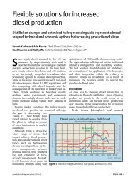
<strong>High</strong> <strong>capacity</strong> <strong>distillation</strong> <strong>revamps</strong><br />
A review of fundamental tray design principles used to increase column <strong>capacity</strong>.<br />
Understanding how high-<strong>capacity</strong> trays work assists in selection and design<br />
Daryl Hanson and Edward Hartman Process Consulting Services Inc<br />
In the past 10 years the mass transfer industry<br />
has developed a number of tray designs to<br />
increase column <strong>capacity</strong> by 10–30 per cent<br />
over well-designed conventional trays. While<br />
some of these trays, such as UOP’s and Shell’s<br />
have been in service for more than 20 years,<br />
several have only been commercialised in the<br />
past five. <strong>High</strong> <strong>capacity</strong> tray designs employ<br />
several different mechanical features to increase<br />
<strong>capacity</strong>.<br />
Maximising tray hydraulic <strong>capacity</strong> always<br />
reduces tray efficiency and/or operating flexibility.<br />
Balancing <strong>capacity</strong>, efficiency, and operating<br />
flexibility is the challenge facing the engineer<br />
performing a revamp. Some designs have inherently<br />
more efficiency due to the longer distance<br />
the liquid travels across the tray. Others have<br />
extremely high <strong>capacity</strong>, lower efficiency and<br />
little turndown. Which high <strong>capacity</strong> tray is<br />
needed depends on the specific process<br />
objectives.<br />
<strong>High</strong> <strong>capacity</strong> trays increase column vapour<br />
and liquid <strong>capacity</strong> by increasing active area,<br />
increasing downcomer <strong>capacity</strong>, decreasing weir<br />
loading and reducing hydraulic gradient.<br />
Trays flood when the liquid and/or the vapour<br />
rate exceed the <strong>capacity</strong> of the particular design.<br />
In some cases an optimised conventional tray<br />
will debottleneck the column. In those instances<br />
where it is necessary to use high <strong>capacity</strong> trays,<br />
one or all of the four principles to increase<br />
vapour and liquid handling may be needed.<br />
Often, tray <strong>capacity</strong>, column efficiency, and operating<br />
flexibility will need to be balanced to meet<br />
revamp objectives. Two case studies, described<br />
later, highlight this balance.<br />
Tray <strong>capacity</strong><br />
Trays flood because the active area and/or the<br />
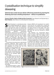
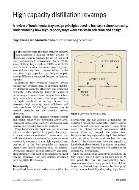
Figure 1 Conventional two-pass tray<br />
downcomers are not capable of handling the<br />
operating vapour and liquid rates. Figure 1 shows<br />
a conventional two-pass tray where liquid flows<br />
down the column through downcomers, while<br />
vapour flows up through the active area.<br />
Incipient flooding begins when liquid is entrained<br />
with the rising vapour and reaches the tray<br />
above. If the downcomers have the <strong>capacity</strong> to<br />
handle both the entrained liquid plus the normal<br />
liquid flow, then fractionation will suffer but the<br />
column will be operable.<br />
Once the downcomer <strong>capacity</strong> is exceeded, the<br />
tray vapour space begins to fill with liquid. At<br />
this point the tray will hydraulically flood,<br />
common symptoms being periodic loss of level<br />
below the flooded trays followed by “dumping”<br />
of the accumulated liquid causing high levels.<br />
www.digitalrefining.com/article/1000325 PTQ Q4 2001 1
Figure 2 Jet (vapour) flooding<br />
When trays flood the column pressure drop<br />
increases.<br />
Trays fractionate by mixing the liquid and<br />
vapour phases together on and above the active<br />
area. The mixed phases separate by Stoke’s Law<br />
with the liquid settling onto the tray deck or into<br />
the top of the downcomer, while liquid-free<br />
vapour rises up the column through the next<br />
tray.<br />
Jet flooding occurs when the localised velocity<br />
through the tray deck is high enough to entrain<br />
liquid to the tray above (Figure 2). Jet flooding<br />
is common in low and moderate pressure services<br />
such as atmospheric crude, FCC main<br />
fractionator, or naphtha splitters. These low to<br />
moderate pressure systems have high vapour<br />
rates and relatively low liquid rates in the fractionating<br />
sections.<br />
Tray downcomers must have the <strong>capacity</strong> to<br />
handle the liquid flowing from one tray to the<br />
next without backing liquid onto the tray deck. A<br />
downcomer can flood by two distinct mechanisms.<br />
Downcomer choke flood occurs when the<br />
rate of liquid entering the top of the downcomer<br />
is too high to allow entrained vapour to<br />
disengage.<br />
The downcomer chokes with liquid and vapour,<br />
and when it does the liquid level on the tray deck<br />
builds up and the column floods. On a simple<br />
basis, downcomer backup flood occurs when the<br />
liquid and froth level in the downcomer exceeds<br />
the tray spacing plus the weir height. Liquid fills<br />
the normal vapour space above the tray deck,<br />
causing flooding.<br />
Downcomer backup is impacted on by several<br />
tray design parameters with the pressure loss<br />
components shown below:<br />
• Dry tray pressure drop – vapour induced loss<br />
• Weir height – set by tray designer<br />
• Weir crest (height of liquid flowing over the<br />
weir) – gpm/inch of weir<br />
• Liquid gradient<br />
• Pressure loss under the downcomer or through<br />
dynamic seal – velocity<br />
Downcomer backup determines the maximum<br />
and minimum operable liquid rates through a<br />
high <strong>capacity</strong> tray, assuming choke is not occurring.<br />
There must be enough liquid height in the<br />
downcomer to overcome the pressure drop of the<br />
various components.<br />
Total liquid height in a downcomer results<br />
from the dry tray pressure-drop (vapour induced<br />
pressure drop through the sieve holes or valves),<br />
weir height, height of liquid flowing over the<br />
weir (gpm/inch of weir), liquid gradient and<br />
pressure loss caused by liquid flowing under the<br />
downcomer or through the dynamic seal.<br />
Liquid level on the tray deck is not uniform<br />
and this reduces tray <strong>capacity</strong>. The liquid gradient<br />
is the driving force needed to push the liquid<br />
across the tray from inlet to outlet. This gradient<br />
causes non-uniform vapour flow rate through the<br />
active area with the variability depending on the<br />
magnitude of the gradient. Liquid gradient<br />
causes high vapour velocity near the outlet weirs,<br />
which results in localised flooding of the tray<br />
active area.<br />
<strong>High</strong> <strong>capacity</strong> tray <strong>revamps</strong> need to balance<br />
hydraulic <strong>capacity</strong>, turndown, and column efficiency<br />
to meet fractionation objectives. Each<br />
factor impacting on tray <strong>capacity</strong> should be<br />
reviewed independently. In practice, the designer<br />
concurrently evaluates all the factors involved,<br />
otherwise an unwanted limit can be created.<br />
Increasing active area<br />
Tray active area is the part of the tray where the<br />
vapour flows through the valve or sieve holes.<br />
Increasing vapour rate requires more active area<br />
assuming the downcomer is not restricting<br />
<strong>capacity</strong>. For instance, increasing tray active area<br />
by 15 per cent will increase the vapour handling<br />
2 PTQ Q4 2001 www.digitalrefining.com/article/1000325
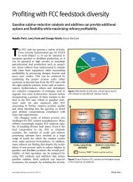
Figure 3 Downcomer flooding: choke and backup<br />
<strong>capacity</strong> by about 15 per cent, all other factors<br />
being equal. Conventional trays have a top downcomer,<br />
bottom downcomer and active areas.<br />
Reducing one or both of the downcomer areas<br />
can be used to increase active area.<br />
Increasing active area, assuming the top downcomer<br />
area cannot be changed, requires less<br />
bottom downcomer area. Conventional trays<br />
have a solid plate at the bottom of the downcomer<br />
(inlet panel). <strong>High</strong> <strong>capacity</strong> designs either<br />
heavily slope the downcomer from top to bottom<br />
or they truncate the downcomer above the tray<br />
deck. While both increase active area, the heavily<br />
sloped downcomers maintain the downcomer<br />
height. This maximises liquid handling<br />
flexibility.<br />
However, as the number of tray passes<br />
increases, the heavily sloped tray inlet panel will<br />
take up a significant amount of bottom downcomer<br />
area. Alternatively, the downcomer can be<br />
truncated above the tray deck. This eliminates<br />
the tray inlet panel (solid plate) and maximises<br />
active area for any given top downcomer area.<br />
Most high <strong>capacity</strong> trays will either heavily slope<br />
or truncate the downcomer to increase active<br />
area. One version of Koch-Glitsch’s Superfrac<br />
tray has very heavily sloped downcomers, while<br />
other high <strong>capacity</strong> trays use truncated downcomers<br />
to maximise <strong>capacity</strong>. Ultimate <strong>capacity</strong><br />
and operating flexibility will determine which<br />
design should be implemented.<br />
Increasing active area, while maximising<br />
downcomer height improves liquid handling<br />
flexibility. UOP’s MD tray was the first commercial<br />
application of a truncated downcomer. This<br />
concept totally eliminates the bottom downcomer<br />
area and maximises active area.<br />
Subsequently Shell developed the HiFi and<br />
Calming Section trays. Shell trays are designed<br />
and manufactured by Sulzer Chemtech.<br />
Other tray vendors, including Saint-Gobain<br />
NorPro and ACS, have applied truncated downcomers<br />
to maximise active area. Increasing active<br />
area lowers vapour velocity, which decreases the<br />
spray or froth height on the tray. This unloads<br />
the trays, allowing vapour rate to be increased.<br />
Increasing downcomer <strong>capacity</strong><br />
Maximum tray liquid rate is limited by downcomer<br />
choke or backup flood. Once either of<br />
these limits is reached, the tray begins to fill with<br />
liquid. Both potential downcomer flooding mechanisms<br />
must be assessed when revamping a<br />
tower (Figure 3).<br />
Downcomer choke occurs because the top<br />
downcomer area is not large enough to concurrently<br />
separate the vapour and allow liquid to<br />
flow into the downcomer. Vapour is always<br />
entrained with the liquid entering the downcomers,<br />
the quantity being a function of the<br />
difference between the vapour and liquid densities,<br />
weir loading, and the liquid surface tension.<br />
<strong>High</strong>-pressure <strong>distillation</strong>, such as depropanisers<br />
and deethanisers, requires large downcomers<br />
due to the system properties. The top area must<br />
be large enough for the entrained vapour to flow<br />
www.digitalrefining.com/article/1000325 PTQ Q4 2001 5
Shell HiFi tray Koch-Glitsch Superfrac tray<br />
out of the downcomer while liquid is flowing into<br />
the downcomer. Often, the various hydraulic<br />
calculation programs do not address downcomer<br />
choke flood.<br />
Downcomer flooding by backing up causes the<br />
liquid or froth height in the downcomer to overflow<br />
the tray weir. Backup flood can be caused<br />
by any of the components affecting liquid height<br />
in the downcomer, including dry tray pressure<br />
drop, weir height, height of liquid over the weir,<br />
gradient, and head loss under the downcomer or<br />
through the dynamic seal. Increasing the active<br />
area, increasing hole area on the tray, or using<br />
lower pressure drop valves or sieve decks reduces<br />
dry tray pressure drop and lowers downcomer<br />
backup.<br />
Maximum hole area as a percentage of active<br />
area for small movable valves and sieve holes is<br />
approximately 15 per cent and 13 per cent<br />
respectively, to maintain vapour rate flexibility.<br />
<strong>High</strong>er hole area will further reduce pressure<br />
drop and increase vapour <strong>capacity</strong>; however, it<br />
causes weeping and loss of efficiency when the<br />
vapour rate is reduced. Using open area above<br />
these guidelines has caused instability and low<br />
tray efficiency.<br />
Truncated downcomers use slots or holes in<br />
the bottom downcomer plates to seal the downcomers<br />
and prevent vapour flow up the<br />
downcomers. The downcomer slot area and<br />
downcomer height largely determine the liquid<br />
handling flexibility. Downcomer height is tray<br />
spacing minus the height of the truncated downcomer<br />
above the tray floor. Increasing the<br />
downcomer clearance on a heavily sloped tray or<br />
the slot area in the truncated downcomer will<br />
lower backup. These also reduce liquid turndown<br />
because the downcomer can unseal.<br />
Once a downcomer unseals, vapour flows up<br />
the downcomer and tray <strong>capacity</strong> and efficiency<br />
is reduced. Trays have been known to enter into<br />
an unstable dual-flow mode.<br />
Decreasing weir loading<br />
Weir loading is a measure of the amount of<br />
liquid flowing over a unit of weir length (gpm/<br />
inch of weir). Decreasing the weir loading<br />
increases vapour <strong>capacity</strong>, decreases the height<br />
of liquid over the weir (weir crest), increases the<br />
downcomer <strong>capacity</strong> (gpm/ft 2 liquid entering the<br />
top downcomer), and reduces liquid gradient<br />
across the tray.<br />
Maximum tray vapour <strong>capacity</strong> occurs at<br />
approximately 3–4gpm/in of weir, assuming all<br />
other parameters being equal. Tray <strong>capacity</strong> will<br />
increase by 10 per cent when weir loading is<br />
reduced from 8 to 3gpm/in of weir. Reducing<br />
weir loading requires more weir length.<br />
Conventional and many high <strong>capacity</strong> trays use<br />
one-, two-, four- – and very rarely six-pass –<br />
trays to increase weir length. The maximum<br />
number of passes is set by the column diameter,<br />
liquid rate and vapour rate.<br />
Minimum column diameter for a two-, four-,<br />
and six-pass tray is approximately 5, 11 and 14ft,<br />
respectively. Once column diameter is at or<br />
above the minimum, the number of passes can<br />
be selected based on the required weir length<br />
needed to control the weir loading. Increasing<br />
the weir length (more tray passes) decreases the<br />
flow path length (FPL). Once the FPL drops<br />
below about 16in it is not possible to inspect the<br />
trays by removing the tray panels. Decreasing<br />
the FPL also reduces tray efficiency and may<br />
4 PTQ Q4 2001 www.digitalrefining.com/article/1000325
equire higher vapour and liquid rates to meet<br />
the desired fractionation.<br />
Some high <strong>capacity</strong> tray designs, such as the<br />
Shell HiFi, allow the number of downcomers to<br />
be customised to the specific liquid rate so that<br />
optimum weir loading is achieved. This maximises<br />
tray <strong>capacity</strong>. At other times, the number of<br />
downcomers can be selected to maximise tray<br />
efficiency, while meeting the column <strong>capacity</strong><br />
objectives.<br />
Reducing weir loading has several other benefits.<br />
It reduces the liquid height flowing over the<br />
weir. This decreases the liquid level on the tray<br />
and decreases downcomer backup. Reducing<br />
weir loading also decreases the downcomer top<br />
area required to disengage vapour and liquid in<br />
the top of the downcomer. The liquid flowing<br />
over the weir travels less horizontal distance,<br />
which reduces the required downcomer top area<br />
and allows more active area.<br />
Reducing hydraulic gradient<br />
Liquid gradient provides the driving force to<br />
push liquid across the tray’s flow path length.<br />
Increasing flow path length will increase the<br />
liquid gradient. Conventional valves restrict<br />
liquid flow and increase hydraulic gradient when<br />
compared to a sieve tray. Reducing hydraulic<br />
gradient results in more uniform vapour flow<br />
rate through the active area and higher tray<br />
<strong>capacity</strong>. Minimising liquid gradient can increase<br />
tray <strong>capacity</strong> by 6–8 per cent.<br />
Liquid gradient influences vapour flow through<br />
the tray deck because the total pressure drop<br />
across any part of a tray must be constant. Total<br />
tray pressure drop includes dry tray (flow<br />
through the valves or sieve holes) and liquid<br />
pressure drop. Conventional and high <strong>capacity</strong><br />
cross-flow trays have the highest liquid level and<br />
liquid density where liquid enters the active area.<br />
Liquid head at the tray inlet is the highest, and<br />
is lowest at the outlet weir.<br />
Vapour flow is highest where liquid head is the<br />
lowest because more vapour- induced pressure<br />
drop is required to meet the constant total pressure<br />
loss criteria across each section of the tray.<br />
Special design features such as directional<br />
valves, slots, and bubble promoters can be used<br />
to minimise liquid gradient and aerate the liquid<br />
on the tray to a more uniform density. Using<br />
vapour to push the liquid across the tray reduces<br />
liquid gradient. The Koch-Glitsch Superfrac tray<br />
NorproTriton tray<br />
uses directional devices to minimise gradient<br />
and maximise <strong>capacity</strong>. In recent years, several<br />
tray vendors have designed their valves to push<br />
the liquid across the tray including Saint-Gobain<br />
Norpro’s Triton and ACS Max Flow.<br />
Efficiency and <strong>capacity</strong><br />
Column efficiency, <strong>capacity</strong>, and operating flexibility<br />
must be balanced when applying high<br />
<strong>capacity</strong> trays. Improving column efficiency can<br />
reduce the required vapour and liquid rate for a<br />
given separation requirement. The specific <strong>distillation</strong><br />
system will determine whether efficiency<br />
has a meaningful impact on vapour and liquid<br />
load.<br />
The number of trays and the efficiency of each<br />
tray set the column efficiency. Fractionation<br />
requirements and column efficiency determine<br />
the tray vapour and liquid loads. Revamps need<br />
to balance the number of trays, tray efficiency,<br />
tray <strong>capacity</strong> and liquid rate flexibility<br />
Vessel height and tray spacing determine the<br />
number of trays that will fit in an existing<br />
column. Process simulation with the appropriate<br />
VLE and transport property methods are<br />
required to determine the reflux ratio and<br />
column efficiency relationship, as well as the<br />
tray-by-tray liquid and vapour loads. Some<br />
columns have extreme vapour and liquid rate<br />
variability; therefore, tray spacing in the bottom<br />
of the column can be increased, while reducing<br />
tray spacing elsewhere. Lowering the tray spacing<br />
reduces tray <strong>capacity</strong> by the square root of<br />
the tray spacing ratio. For instance, a tray on<br />
12in spacing will have approximately 70 per cent<br />
of the <strong>capacity</strong> of a tray on 24in. Therefore, the<br />
www.digitalrefining.com/article/1000325 PTQ Q4 2001 5
optimum number of trays is a balance between<br />
column efficiency and tray <strong>capacity</strong>. Lower tray<br />
spacing also reduces liquid rate flexibility.<br />
Tray efficiency is a complex function of the<br />
<strong>distillation</strong> system properties (key components,<br />
relative volatility, viscosity, surface tension, etc)<br />
and the tray design. For a given <strong>distillation</strong><br />
system, tray efficiency decreases as flow path<br />
length is reduced. Heavily sloping or truncating<br />
the downcomer can maximise FPL and increase<br />
efficiency. Directional valve or bubble promoters<br />
allow longer flow path lengths while minimising<br />
liquid gradient.<br />
Liquid flow patterns can be improved through<br />
special design features such as the side-downcomer<br />
layout or directional valves on the<br />
Koch-Glitsch Superfrac tray. These help minimise<br />
stagnant zones and improve tray efficiency.<br />
Operability and flexibility<br />
Some of the high <strong>capacity</strong> tray design features,<br />
such as the truncated downcomer, influence<br />
operability and flexibility. The area under the<br />
truncated downcomer uses valves, directional<br />
valves, or bubble promoters to increase vapour<br />
<strong>capacity</strong> and reduce liquid gradient.<br />
Truncated downcomers must be sealed so that<br />
liquid flows through the downcomers, while<br />
vapour flows through the active area. If a significant<br />
amount of vapour flows up the downcomer,<br />
liquid is prevented from flowing down. Unsealed<br />
downcomers can cause poor operating stability,<br />
reduce tray <strong>capacity</strong>, and lower tray efficiency.<br />
Most conventional trays have an outlet weir<br />
height equal to or greater than the downcomer<br />
clearance. This creates a positive seal and<br />
prevents vapour flow up the downcomer. All<br />
high <strong>capacity</strong> and some conventional trays use a<br />
dynamic seal. The liquid rate flowing under the<br />
downcomers must be high enough to develop the<br />
seal. Truncated downcomers have a plate at the<br />
bottom with holes or slots. A minimum liquid<br />
rate is needed to create the seal and prevent<br />
vapour passage.<br />
Maximum liquid rate occurs once the downcomer<br />
fills with froth and backs liquid onto the<br />
tray above. Truncated or dynamically sealed<br />
downcomers can only operate between these two<br />
limits. This is important during the review of<br />
start-up procedures and when establishing the<br />
liquid rates required for stable operation.<br />
When the downcomer unseals, vapour flows<br />
up the downcomer. Once the vapour flow is high<br />
enough to prevent liquid flow into the downcomers<br />
or the pressure drop through the valve or<br />
sieve holes gets low enough, then liquid flows<br />
through the tray deck. Poor vapour-liquid mixing<br />
occurs and tray efficiency decreases. <strong>High</strong> <strong>capacity</strong><br />
trays can operate as dual-flow trays under<br />
some conditions. Vapour and liquid alternately<br />
flow through the same hole. Tray efficiency loss<br />
of 30–40 per cent has been observed in a xylene<br />
splitter when the downcomers unseal.<br />
Another potential problem area is the distance<br />
from the bottom of the truncated downcomer to<br />
the tray deck. It must be high enough to prevent<br />
the froth on the tray from reaching it, while<br />
providing sufficient cross-sectional area between<br />
the tray deck and edge of the truncated downcomer<br />
for vapour to escape. If the downcomer is<br />
too close to the tray deck, then the vapour flow<br />
area is choked. Thus, the active area under the<br />
downcomer is ineffective, which lowers overall<br />
tray <strong>capacity</strong>.<br />
If excess height is used, the column liquid<br />
<strong>capacity</strong> is reduced because the downcomer<br />
height is very short.<br />
<strong>High</strong> sieve or valve hole area in the active area<br />
also controls the tray operating stability. <strong>High</strong><br />
tray hole areas increase vapour <strong>capacity</strong>, but<br />
lower the vapour rate flexibility. As a rule, the<br />
higher the <strong>capacity</strong> through a given column<br />
diameter, the less flexibility is available. In fact,<br />
extreme tray designs have approached pointoperation<br />
and will only operate over a very<br />
limited range of vapour and liquid rates. They<br />
have no turn down capability.<br />
Case Study 1: Column efficiency<br />
Revamping a C 3 splitter with improved efficiency,<br />
high <strong>capacity</strong> trays increased column feed rate<br />
by 7 per cent, while maintaining fractionation.<br />
The column in this case study was operating at<br />
two distinct constraints: condenser and tray<br />
<strong>capacity</strong> limits. C 3 splitter reflux ratio and tray<br />
loading will decrease as column pressure is<br />
reduced because the propylene/propane relative<br />
volatility increases.<br />
Concurrently, low pressure reduces the propylene<br />
stream condensing temperature, which can<br />
lower the condenser <strong>capacity</strong> through reduced<br />
cooling water and propylene stream temperature<br />
differences.<br />
In this example, during low pressure operation<br />
6 PTQ Q4 2001 www.digitalrefining.com/article/1000325
the reflux ratio was lowest, but the<br />
condenser <strong>capacity</strong> limited unit feed<br />
rate. Increasing tower pressure alleviated<br />
the condensing limitation but<br />
increased the tray loads and flooded<br />
the column. Prior to the revamp, the<br />
column had high <strong>capacity</strong> trays,<br />
however, they had relatively low<br />
efficiency.<br />
C 3 splitter fractionation is more<br />
complex than many refinery services<br />
because of the impact of operating<br />
pressure and column efficiency on tray<br />
loading. Many times, when there is a<br />
bottleneck in column <strong>capacity</strong>, high<br />
<strong>capacity</strong> trays are specified without<br />
looking at the big picture and formulating<br />
the best revamp strategy.<br />
Quantifying the existing column and<br />
auxiliary (condenser) equipment limitations<br />
is critical before any revamp.<br />
Column efficiency evaluation showed<br />
current operation at the inflection point<br />
of the reflux (or reboil, reflux ratio)<br />
versus stage curve. Understanding fractionation<br />
efficiency sensitivity was<br />
essential to finding the best solution.<br />
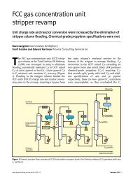
Figure 4 is a curve for the separation,<br />
which analyses the reflux ratio versus<br />
stage curves. There are three distinct<br />
zones of operation shown on Figure 4<br />
and described in Table 1. They are<br />
represented by Zones A, B and C.<br />
For this splitter, the existing operation was on<br />
the borderline of Zones A and B. The most costeffective<br />
revamp strategy was to increase tray<br />
efficiency to stay within the condenser constraint.<br />
The existing splitter had 100 high <strong>capacity</strong> trays.<br />
The trays were set on 15in tray spacing<br />
throughout the column. The single phase feed<br />
entered the tower onto tray 45. The condenser<br />
used cooling tower water. The existing trays were<br />
a high <strong>capacity</strong> and low efficiency design.<br />
Column peripheral equipment and utility limitations<br />
prevented increasing feed rate with the<br />
low efficiency trays. The existing cooling water<br />
condensers were limited to 104 million Btu/hr<br />
due to cooling water availability.<br />
Increasing the cooling water supply would have<br />
required another cell to be added to the existing<br />
cooling tower. This required major capital investment<br />
and it could not be justified. Hence the<br />
Figure 4 Column efficiency vs reflux ratio curve<br />
Zone Sensitivity to efficiency Result<br />
A <strong>High</strong> Tower benefits from addition of stages or<br />
increased tray efficiency<br />
B Moderate Tower may not reap benefits of additional<br />
stages<br />
C Low Revamp to higher tray spacing is beneficial<br />
to gain <strong>capacity</strong>. Revamp with low<br />
efficiency trays is a good strategy<br />
Table 1<br />
Fractionation efficiency sensitivity<br />
condenser limit was a significant factor in the<br />
revamp. When operating in Zone A and B,<br />
increasing column <strong>capacity</strong> without increasing<br />
condenser <strong>capacity</strong> requires more column<br />
efficiency.<br />
Increasing column operating pressure raises<br />
the overhead vapour temperature and increases<br />
condensing <strong>capacity</strong> by raising propylene<br />
condensing temperature. However, this increase<br />
also raises tray vapour and liquid rates due to<br />
decreasing relative volatility as pressure<br />
increases. Both the condenser and tray capacities<br />
were limiting the unit feed rate. Column feed<br />
rate was a balance between the limitation<br />
imposed by the trays and the overhead condenser<br />
system.<br />
The revamp strategy was to increase the<br />
number of fractionation stages by using higher<br />
efficiency trays. The new tray design used a<br />
longer flow path length and design features to<br />
www.digitalrefining.com/article/1000325 PTQ Q4 2001 7
Figure 5 Increasing liquid handling flexibility<br />
minimise liquid gradient. Since the tower was<br />
operating in the Zone A part of the curve, additional<br />
efficiency reduced the required reflux<br />
ratio. Lower reflux ratio translated into greater<br />
throughput at existing condenser limitations.<br />
After the revamp the feed rate increased by 7 per<br />
cent.<br />
Post revamp operating tray efficiency increased<br />
and the reflux ratio decreased from 10.4:10.6 to<br />
9.2:9.4. Further analysis of product and intermediate<br />
tower samples indicates the tray efficiency<br />
is 88–92 per cent. This is an efficiency increase<br />
of 15 percentage points over the low efficiency<br />
tray. This revamp illustrates the strategy of<br />
revamping a tower for additional column efficiency<br />
when operating in Zone A or B of the<br />
stage versus reflux curve.<br />
Case Study 2: Improved flexibility<br />
In the previous case study, increasing column<br />
efficiency was the correct strategy given the<br />
constraints. In this case, an FCC depropaniser<br />
was limited by liquid handling flexibility. The<br />
column was operating in the middle of Zone C of<br />
Figure 4; therefore, reflux ratio is not sensitive<br />
to the number of trays and the tray efficiency.<br />
The column had 56 trays on 16in tray spacing.<br />
The design used short 12in deep truncated downcomers,<br />
which set the maximum and minimum<br />
liquid rate. Reboiler fouling limited available<br />
heat input as run-length progressed, therefore<br />
reflux ratio decreased. This reduced the liquid<br />
rates inside the column. Due to the short spacing<br />
of the internals, the liquid flexibility on the trays<br />
was small and the tray downcomers unsealed.<br />
This caused the trays to operate in a dual-flow<br />
manner with liquid and vapour flow through the<br />
downcomers and active area.<br />
A revamp strategy was formulated to increase<br />
operating flexibility. The 56 trays were analysed<br />
and it was confirmed that unsealing of the downcomers<br />
occurred as the reboiler fouled. A simple<br />
fix would be to retrofit the existing truncated<br />
downcomer dynamic seals with a lower slot area<br />
to increase liquid head loss and increase downcomer<br />
backup. This would eliminate the<br />
unsealing to meet the minimum rates, but then<br />
the design would not meet the maximum liquid<br />
rate.<br />
The problem was operating flexibility due to<br />
short tray spacing. Short tray spacing, in<br />
conjunction with truncated downcomers, yields<br />
low liquid rate flexibility.<br />
The revamp strategy focused on understanding<br />
the reflux versus column efficiency curve for this<br />
system. A key question was: “Does this tower<br />
need 56 trays for the required separation?”<br />
A revamp strategy was formulated based on<br />
future operating conditions of 115 per cent of<br />
current rates, while improving product separation<br />
due to higher reflux ratio. Operating range<br />
was specified as 105 per cent of design (115 per<br />
8 PTQ Q4 2001 www.digitalrefining.com/article/1000325
cent of current) with a turndown to 50 per cent<br />
of rates.<br />
The answer to this question comes directly<br />
from the reflux ratio versus stage (column efficiency)<br />
curve. The tower had 56 trays and was<br />
operating in the Zone C region of the curve; high<br />
tray count (more efficiency) was not a benefit.<br />
Therefore, a revamp strategy to decrease the<br />
number of trays was developed.<br />
The optimal revamp strategy was to reduce the<br />
number of trays from 56 to 44 new trays (Figure<br />
5). The tray spacing was increased to 20in. This<br />
yielded a tray vapour <strong>capacity</strong> increase of 12 per<br />
cent (square root of 20/16) with the additional<br />
benefits of improved liquid rate flexibility due to<br />
increased downcomer height. The downcomer<br />
height is a function of tray spacing and the<br />
distance of the truncated downcomer from the<br />
tray deck.<br />
As the truncated height was kept essentially<br />
constant, the downcomer plus weir height was<br />
increased by over 4in or approximately 25 per<br />
cent.<br />
By moving the operating point from Zone C to<br />
a Zone B operation, fewer trays are required<br />
without materially affecting the reboiler duty,<br />
condenser duty or reflux requirements. The key<br />
to using this curve is to understand the separation<br />
and the relative volatility of the specific<br />
system.<br />
Small errors in relative volatility in a low relative<br />
volatility system, such as a C 3 splitter, will<br />
result in large reflux ratio errors and major<br />
equipment design problems. With high relative<br />
volatility systems, like an FCC depropaniser,<br />
small relative volatility errors have much less<br />
impact. This revamp illustrates the strategy of<br />
revamping a tower for additional tray <strong>capacity</strong><br />
when operating in Zone C of the column efficiency<br />
curve. Column <strong>capacity</strong> and operating<br />
flexibility were driven by tray hydraulics, not<br />
column efficiency.<br />
Links<br />
More articles from: Process Consulting services<br />
More articles from the following categories:<br />
Mass Transfer & separation<br />
Revamps, shutdowns and Turnarounds<br />
www.digitalrefining.com/article/1000325 PTQ Q4 2001 9