Meccano model of the FWD - Hell's Confetti
Meccano model of the FWD - Hell's Confetti
Meccano model of the FWD - Hell's Confetti

You also want an ePaper? Increase the reach of your titles
YUMPU automatically turns print PDFs into web optimized ePapers that Google loves.
THE MECCANO MOTOR CHASSIS PART 5<br />
THE 1933 ALVIS FRONT WHEEL DRIVE<br />
Roger Marriott<br />
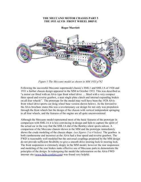
Figure 1 The <strong>Meccano</strong> <strong>model</strong> as shown in MM 1933 p782<br />
Following <strong>the</strong> successful <strong>Meccano</strong> super<strong>model</strong> chassis’sSML1 and SML1A <strong>of</strong> 1928 and<br />
1931 a fur<strong>the</strong>r chassis design appeared in <strong>the</strong> MM in October 1933. This was described as<br />
“a motor car fitted with an Alvis type front wheel drive … fitted with a very compact<br />
three speed and reverse gearbox, a neat single plate clutch and internal expanding brakes<br />
on all four wheels”. The prototype for <strong>the</strong> <strong>model</strong> may wel have been <strong>the</strong> 1928 Alvis<br />
front wheel drive sports car (long wheel base version shown below). As <strong>the</strong> forward to<br />
<strong>the</strong> Alvis brochure states this was a revolutionary car design for not only was propulsion<br />
through <strong>the</strong> front wheels but <strong>the</strong> design <strong>of</strong> <strong>the</strong> chassis with vertical independent springing<br />
to all four wheels, and <strong>the</strong> features <strong>of</strong> <strong>the</strong> engine are all quite unconventional.<br />
Although <strong>the</strong> <strong>Meccano</strong> <strong>model</strong> represented most <strong>of</strong> <strong>the</strong> basic features <strong>of</strong> <strong>the</strong> prototype in<br />
comparison with SML1A it is less convincing in design and fails to capture <strong>the</strong> spirit <strong>of</strong><br />
<strong>the</strong> actual car in <strong>the</strong> way that <strong>the</strong> SML1A did <strong>of</strong> <strong>the</strong> Bentley silent sports saloon. A<br />
comparison <strong>of</strong> <strong>the</strong> <strong>Meccano</strong> chassis shown in <strong>the</strong> MM and <strong>the</strong> prototype immediately<br />
shows <strong>the</strong> crude <strong>model</strong>ing <strong>of</strong> <strong>the</strong> chassis shape. (see figures 3 to 4 below). The gearbox is<br />
both cumbersome and incorrect as <strong>the</strong> Alvis had a four speed and reverse gearbox. The<br />
<strong>FWD</strong> is reasonably well <strong>model</strong>ed but <strong>the</strong> universal couplings proposed by <strong>the</strong> MM design<br />
do not provide sufficient flexibility to give a smooth drive steering lock to steering lock.<br />
The front suspension is extremely sloppy in <strong>the</strong> MM <strong>model</strong>, however <strong>the</strong> rear suspension<br />
and <strong>model</strong>ing <strong>of</strong> <strong>the</strong> rear brakes make effective use <strong>of</strong> <strong>Meccano</strong> parts to demonstrate <strong>the</strong><br />
principles <strong>of</strong> <strong>the</strong> design. In redesigning <strong>the</strong> <strong>model</strong> <strong>the</strong> information on <strong>the</strong> Alvis <strong>FWD</strong><br />
internet site (www.hells-confetti.com) was found very helpful.
Figure 2: 1929 Alvis front wheel drive sports tourer<br />
The successful use <strong>of</strong> front wheel drive for racing in USA, led Alvis to produce, in 1928,<br />
road cars using this system, <strong>the</strong> first manufacturer <strong>of</strong> any size to do so. This was an<br />
incredibly courageous move because <strong>the</strong> technology involved was radical and difficult.<br />
Technically, <strong>the</strong> Alvis <strong>FWD</strong> is extremely interesting, featuring a gear driven overhead<br />
camshaft, inboard front brakes and all-independent suspension in addition to <strong>the</strong> front<br />
wheel drive. The 1482 cc four cylinder engine was turned back-to-front to drive through<br />
a clutch and 4 speed gearbox, in front <strong>of</strong> <strong>the</strong> engine, to a differential and substantial nonconstant<br />
velocity joints. These latter resulted in some "fight" at <strong>the</strong> steering wheel when<br />
cornering. A conventional right hand gear change lever was used, in contrast to many<br />
o<strong>the</strong>r fwd cars where <strong>the</strong> gear lever migrated to <strong>the</strong> dashboard. Front suspension was by<br />
four transverse quarter elliptic springs on each side, whilst at <strong>the</strong> rear single longitudinal<br />
reversed quarter elliptics operated in conjunction with rear-hung radius arms. Many cars<br />
were fitted with superchargers; this instrument increased power from 50 bhp to 75. Two<br />
chassis lengths, 8'6" and 10', were available, for two or four seater open coachwork,<br />
although some saloons were also made. The short chassis types were denoted FA and FD,<br />
<strong>the</strong> long ones FB and FE. FC referred to a few special racing versions with fixed cylinder<br />
heads.<br />
There are some 35 survivors out <strong>of</strong> a total production <strong>of</strong> about 150 front-wheel-drive cars<br />
produced from 1928 to 1931. Two cars ran at Le Mans in 1928 and came 6 th and 9 th<br />
overall, a very fine achievement. Maintenance is relatively complicated and <strong>the</strong> cars were<br />
ra<strong>the</strong>r noisy, complex and required owners to learn different driving techniques from<br />
those <strong>the</strong>n regarded as normal.
Figure 3 The Alvis front wheel drive rolling chassis<br />
In addition to <strong>FWD</strong> <strong>the</strong> Alvis also incorporated some unconventional design features.<br />
The petrol tank was carried between <strong>the</strong> dashboard and <strong>the</strong> engine bulkhead, and as can<br />
be seen in figure 3, <strong>the</strong> filler is perilously close to <strong>the</strong> engine. The overhead camshaft is<br />
gear driven ra<strong>the</strong>r than by chain. The magneto is carried in a horizontal position forward<br />
<strong>of</strong> <strong>the</strong> engine. Radiator cooling is not assisted by a fan and <strong>the</strong> silencer is an expansion<br />
chamber formed by bifurcation in <strong>the</strong> exhaust tube.<br />
Figure 4: The Alvis <strong>FWD</strong> chassis from above
In building <strong>the</strong> <strong>model</strong> I have attempted to improve on <strong>the</strong> un-prototypical features <strong>of</strong> <strong>the</strong><br />
MM <strong>model</strong>. The chassis has been re<strong>model</strong>ed to better represent <strong>the</strong> Alvis. The gearbox is<br />
<strong>the</strong> revised 4 speed and reverse used in my SML1A which is more compact and<br />
functional than <strong>the</strong> MM 3speed box. Although this is carried forward <strong>of</strong> <strong>the</strong> drive it has<br />
not been found possible to fully replicate <strong>the</strong> layout <strong>of</strong> <strong>the</strong> Alvis with clutch-gearbox<br />
forward <strong>of</strong> <strong>the</strong> engine. The front wheel drive arrangements and suspension have been<br />
re<strong>model</strong>ed to give a more prototypical representation. Only <strong>the</strong> principal revised features<br />
<strong>of</strong> <strong>the</strong> <strong>model</strong> are described.<br />
The Chassis<br />
Figure 5: The re<strong>model</strong>ed Alvis <strong>FWD</strong> <strong>Meccano</strong> chassis(engine and petrol tank removed)<br />
Figure 6 : Revised <strong>model</strong> <strong>of</strong> <strong>the</strong> Alvis <strong>FWD</strong> chassis underside<br />
(note steering, in this view <strong>the</strong> gear change is behind <strong>the</strong> engine and gearbox)
The construction <strong>of</strong> <strong>the</strong> chassis is straight-forward. A box girder is formed from angle<br />
girders and flat girders with cross bracing as shown above using 4 ½ inch girders at <strong>the</strong><br />
front and 6 inch compound girders at <strong>the</strong> rear. The steering rods are shown clearly above.<br />
Front wheel drive and suspension:<br />
Figure 7: front suspension<br />
The front springs consist <strong>of</strong> a 2x2 ½, 2, and 1 ½, inch narrow strips. Double arm cranks<br />
forming <strong>the</strong> wheel bearings are bolted to 1 ½ double angle strips and at <strong>the</strong> lower end<br />
carry a collar which forms a bearing for <strong>the</strong> king pin. The DAS is pivoted between two<br />
early ¾ inch double brackets. The<br />
king pin, a short length <strong>of</strong> rod, is<br />
held secure in a crank and <strong>the</strong> collar.<br />
The double brackets are secured to<br />
<strong>the</strong> springs by collars and a 1 ½ inch<br />
strip links upper and lower springs.<br />
Two universal joints transmit <strong>the</strong><br />
drive to <strong>the</strong> front wheels. The outer<br />
is <strong>the</strong> standard <strong>Meccano</strong> part 140,<br />
for <strong>the</strong> inner one small fork piece is<br />
replaced by two angle brackets fixed<br />
toge<strong>the</strong>r by a threaded pin. The<br />
differential unit is <strong>the</strong> standard<br />
meccano differential without a cage<br />
which is too bulky for <strong>the</strong> space available. Figure 8 wheel bearing and steering<br />
The Braking system<br />
The rear brakes follow <strong>the</strong> design <strong>of</strong> <strong>the</strong> 1933<br />
MM <strong>model</strong>; <strong>the</strong> Bowden cable brakes use<br />
spring cord as a sheath, <strong>the</strong> caliper is operated<br />
by <strong>the</strong> hand brake which pulls <strong>the</strong> 2 inch strips<br />
closer to <strong>the</strong> pulley thus forcing <strong>the</strong>m apart<br />
causing collars in <strong>the</strong> end holes to bind on <strong>the</strong><br />
rim <strong>of</strong> a wheel flange.(see figure 9 opposite)
The front brakes are carried inboard on <strong>the</strong> prototype, ie between <strong>the</strong> differential and <strong>the</strong><br />
constant velocity joints. The redesigned suspension and use <strong>of</strong> two universal joints to<br />
ensure better drive through <strong>the</strong> steering range necessitates a rethink <strong>of</strong> <strong>the</strong> design <strong>of</strong> <strong>the</strong><br />
front braking system used in <strong>the</strong> MM <strong>model</strong>; <strong>the</strong> MM brakes being too wide to fit <strong>the</strong><br />
available space. A number <strong>of</strong> attempts were made to achieve a prototypical brake with<br />
<strong>the</strong> flanged wheel but figure 10 shows a design which<br />
just about fits but uses <strong>the</strong> early large contrate as <strong>the</strong><br />
brake drum instead.(note: an earlier version is shown<br />
in figs 6 & 12) A rubber collar is cut in half and placed<br />
over bolt heads for brake shoes. These bolts also secure<br />
<strong>the</strong> ends <strong>of</strong> a small piece <strong>of</strong> spring cord. The brake is<br />
operated by moving <strong>the</strong> block <strong>of</strong> six fish plates forcing<br />
<strong>the</strong> pawls apart. The redesign <strong>of</strong> <strong>the</strong> front axle and<br />
brakes requires a modification to <strong>the</strong> UJs replacing two<br />
<strong>of</strong> <strong>the</strong> small fork pieces (pn116a) by angle brackets as<br />
shown in figure 12.<br />
Figure 10: redesigned front brake<br />
The brake back plate is bolted to a second wheel disc using <strong>the</strong> ½ inch long bolts which<br />
carry <strong>the</strong> pawls, <strong>the</strong>se bolts also secure <strong>the</strong> wheel discs to <strong>the</strong> frame holding <strong>the</strong> front<br />
wheel differential gear. Thin washers<br />
are used <strong>the</strong> ensure <strong>the</strong> differential<br />
does not move between <strong>the</strong> frames.<br />
Figure 11: re-designed inboard front<br />
brake and differential unit<br />
Gear box and clutch:<br />
Although <strong>the</strong> gearbox and clutch cannot be carried forward <strong>of</strong> <strong>the</strong> engine <strong>the</strong> drive is<br />
arranged as in <strong>the</strong> prototype. In effect <strong>the</strong> normal drive through clutch and gearbox to<br />
differential is turned around ie drive is from left to right in figure 12. In <strong>the</strong> <strong>model</strong> a chain<br />
drive is used from a mains motor beneath a mounting board.
Figure 12 : clutch, gear box and fwd(note inboard brakes and gear change)<br />
A right hand 4 speed and reverse gear change follows <strong>the</strong> standard H gate. The gear<br />
change replicates <strong>the</strong> unusual ALVIS dog and pin striking gear design shown<br />
below(figure 13). In <strong>the</strong> <strong>model</strong> a small fork piece engages gear change activators as <strong>the</strong><br />
gear lever is moved through <strong>the</strong> H gate. A pivot mounted in a bent strip (pn102) carries a<br />
loose colar between <strong>the</strong> “strips” and a coupling beneath, fixed in its centre hole. The low<br />
gear change is controlled through movement <strong>of</strong> <strong>the</strong> upper collar which is extended to<br />
carry a screwed coupling and a collar. This latter is engaged by <strong>the</strong> small fork (shown in<br />
figure 12) linked to <strong>the</strong> gear change lever. The colar is connected by a ¾” bolt to ano<strong>the</strong>r<br />
collar connected to a small fork piece (pn116a) which carries a collar fixed to <strong>the</strong> layshaft<br />
between its fork. As <strong>the</strong> gear lever is moved <strong>the</strong> pivot arm moves forward and back<br />
causing <strong>the</strong> layshaft to slide. For <strong>the</strong> high gear change <strong>the</strong> coupling( beneath <strong>the</strong> bent<br />
strip) is rigidly connected to a small fork fashioned from a 3 hole narrow strip. This traps<br />
a collar fixed to <strong>the</strong> layshaft. The coupling is extended by a large fork piece (pn116) to<br />
form <strong>the</strong> dog.<br />
Figure 13: gear change mechanism
Two views <strong>of</strong> <strong>the</strong> completed <strong>model</strong> with gear change forward <strong>of</strong> <strong>the</strong> engine<br />
This article appeared in <strong>the</strong> Runnymede Mecccano Guild magazine in February 2009. For<br />
more information on <strong>Meccano</strong> goto www.meccanoscene.co.uk. (The original diagrams<br />
and photos <strong>of</strong> <strong>the</strong> actual cars are from <strong>the</strong> “Hels-confeti” internet site thanks to Dr Tony<br />
Cox <strong>of</strong> <strong>the</strong> Alvis Register).