Center Differential Instructions - Traxxas
Center Differential Instructions - Traxxas
Center Differential Instructions - Traxxas

You also want an ePaper? Increase the reach of your titles
YUMPU automatically turns print PDFs into web optimized ePapers that Google loves.
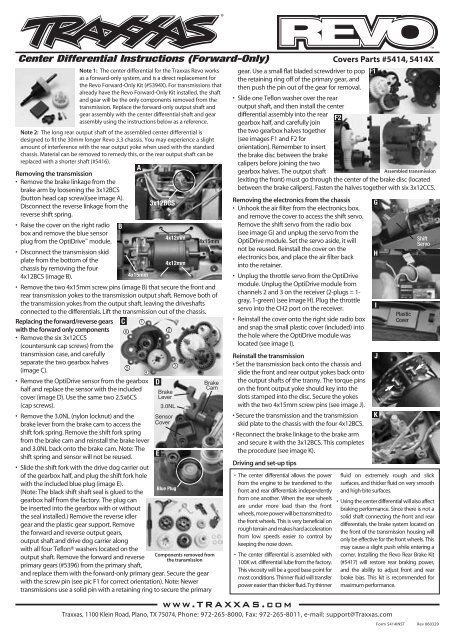
<strong>Center</strong> <strong>Differential</strong> <strong>Instructions</strong> (Forward-Only) Covers Parts #5414, 5414X<br />
Note 1: The center differential for the <strong>Traxxas</strong> Revo works<br />
as a forward-only system, and is a direct replacement for<br />
the Revo Forward-Only Kit (#5394X). For transmissions that<br />
already have the Revo Forward-Only Kit installed, the shaft<br />
and gear will be the only components removed from the<br />
transmission. Replace the forward-only output shaft and<br />
gear assembly with the center differential shaft and gear<br />
assembly using the instructions below as a reference.<br />
Note 2: The long rear output shaft of the assembled center differential is<br />
designed to fit the 30mm longer Revo 3.3 chassis. You may experience a slight<br />
amount of interference with the rear output yoke when used with the standard<br />
chassis. Material can be removed to remedy this, or the rear output shaft can be<br />
replaced with a shorter shaft (#5416).<br />
Removing the transmission<br />
• Remove the brake linkage from the<br />
brake arm by loosening the 3x12BCS<br />
(button head cap screw)(see image A).<br />
Disconnect the reverse linkage from the<br />
reverse shift spring.<br />
• Raise the cover on the right radio<br />
box and remove the blue sensor<br />
plug from the OptiDrive 3x12BCS<br />
module.<br />
• Disconnect the transmission skid<br />
B<br />
4x12mm<br />
4x15mm<br />
plate from the bottom of the<br />
chassis by removing the four<br />
4x12mm<br />
4x12BCS (image B).<br />
4x15mm<br />
• Remove the two 4x15mm screw pins (image B) that secure the front and<br />
rear transmission yokes to the transmission output shaft. Remove both of<br />
the transmission yokes from the output shaft, leaving the driveshafts<br />
connected to the differentials. Lift the transmission out of the chassis.<br />
Replacing the forward/reverse gears C 1<br />
with the forward only components<br />
• Remove the six 3x12CCS<br />
(countersunk cap screws) from the<br />
transmission case, and carefully<br />
6<br />
2<br />
separate the two gearbox halves<br />
(image C).<br />
5<br />
3<br />
• Remove the OptiDrive sensor from the gearbox<br />
half and replace the sensor with the included<br />
cover (image D). Use the same two 2.5x6CS<br />
(cap screws).<br />
• Remove the 3.0NL (nylon locknut) and the<br />
brake lever from the brake cam to access the<br />
shift fork spring. Remove the shift fork spring<br />
from the brake cam and reinstall the brake lever<br />
and 3.0NL back onto the brake cam. Note: The<br />
shift spring and sensor will not be reused.<br />
• Slide the shift fork with the drive dog carrier out<br />
of the gearbox half, and plug the shift fork hole<br />
with the included blue plug (image E).<br />
(Note: The black shift shaft seal is glued to the<br />
gearbox half from the factory. The plug can<br />
be inserted into the gearbox with or without<br />
the seal installed.) Remove the reverse idler<br />
gear and the plastic gear support. Remove<br />
the forward and reverse output gears,<br />
output shaft and drive dog carrier along<br />
with all four Teflon® washers located on the<br />
output shaft. Remove the forward and reverse<br />
primary gears (#5396) from the primary shaft,<br />
Components removed from<br />
the transmission<br />
and replace them with the forward-only primary gear. Secure the gear<br />
with the screw pin (see pic F1 for correct orientation). Note: Newer<br />
transmissions use a solid pin with a retaining ring to secure the primary<br />
A<br />
4<br />
D<br />
Brake<br />
Lever<br />
Sensor<br />
Cover<br />
E<br />
3.0NL<br />
Blue Plug<br />
Brake<br />
Cam<br />
gear. Use a small flat bladed screwdriver to pop<br />
the retaining ring off of the primary gear, and<br />
then push the pin out of the gear for removal.<br />
• Slide one Teflon washer over the rear<br />
output shaft, and then install the center<br />
differential assembly into the rear<br />
gearbox half, and carefully join<br />
the two gearbox halves together<br />
(see images F1 and F2 for<br />
orientation). Remember to insert<br />
the brake disc between the brake<br />
calipers before joining the two<br />
gearbox halves. The output shaft<br />
(exiting the front) must go through the center of the brake disc (located<br />
between the brake calipers). Fasten the halves together with six 3x12CCS.<br />
Removing the electronics from the chassis<br />
• Unhook the air filter from the electronics box,<br />
and remove the cover to access the shift servo.<br />
Remove the shift servo from the radio box<br />
(see image G) and unplug the servo from the<br />
OptiDrive module. Set the servo aside, it will<br />
not be reused. Reinstall the cover on the<br />
electronics box, and place the air filter back<br />
into the retainer.<br />
• Unplug the throttle servo from the OptiDrive<br />
module. Unplug the OptiDrive module from<br />
channels 2 and 3 on the receiver (2-plugs = 1gray,<br />
1-green) (see image H). Plug the throttle<br />
servo into the CH2 port on the receiver.<br />
• Reinstall the cover onto the right side radio box<br />
and snap the small plastic cover (included) into<br />
the hole where the OptiDrive module was<br />
located (see image I).<br />
Reinstall the transmission<br />
• Set the transmission back onto the chassis and<br />
slide the front and rear output yokes back onto<br />
the output shafts of the tranny. The torque pins<br />
on the front output yoke should key into the<br />
slots stamped into the disc. Secure the yokes<br />
with the two 4x15mm screw pins (see image J).<br />
• Secure the transmission and the transmission<br />
skid plate to the chassis with the four 4x12BCS.<br />
• Reconnect the brake linkage to the brake arm<br />
and secure it with the 3x12BCS. This completes<br />
the procedure (see image K).<br />
Driving and set-up tips<br />
• The center differential allows the power<br />
from the engine to be transferred to the<br />
front and rear differentials independently<br />
from one another. When the rear wheels<br />
are under more load than the front<br />
wheels, more power will be transmitted to<br />
the front wheels. This is very beneficial on<br />
rough terrain and makes hard acceleration<br />
from low speeds easier to control by<br />
keeping the nose down.<br />
• The center differential is assembled with<br />
100K wt. differential lube from the factory.<br />
This viscosity will be a good base point for<br />
most conditions. Thinner fluid will transfer<br />
power easier than thicker fluid. Try thinner<br />
www.TRAXXAS.com<br />
<strong>Traxxas</strong>, 1100 Klein Road, Plano, TX 75074, Phone: 972-265-8000, Fax: 972-265-8011, e-mail: support@<strong>Traxxas</strong>.com<br />
F2<br />
F1<br />
G<br />
H<br />
I<br />
J<br />
K<br />
Assembled transmission<br />
Plastic<br />
Cover<br />
Shift<br />
Servo<br />
fluid on extremely rough and slick<br />
surfaces, and thicker fluid on very smooth<br />
and high-bite surfaces.<br />
• Using the center differential will also affect<br />
braking performance. Since there is not a<br />
solid shaft connecting the front and rear<br />
differentials, the brake system located on<br />
the front of the transmission housing will<br />
only be effective for the front wheels. This<br />
may cause a slight push while entering a<br />
corner. Installing the Revo Rear Brake Kit<br />
(#5417) will restore rear braking power,<br />
and the ability to adjust front and rear<br />
brake bias. This kit is recommended for<br />
maximum performance.<br />
Form 5414INST Rev 060329
2552<br />
CCS 3 X 12<br />
3215<br />
CS 2.5 X 6<br />
5157<br />
2552<br />
CCS 3 X 12<br />
Part #5414 <strong>Center</strong> <strong>Differential</strong> Kit<br />
Installation of Part #5417 Dual Rear<br />
Brake Kit is not neccessary, but it is<br />
recommended. Sold seperately<br />
from Part #5417 Dual Rear Brake Kit.<br />
5381<br />
5416<br />
5382<br />
Part #5417 Dual Rear Brake Kit<br />
Requires installation of Part<br />
#5414 <strong>Center</strong> <strong>Differential</strong> Kit.<br />
Sold seperately from Part #5414<br />
<strong>Center</strong> <strong>Differential</strong> Kit.<br />
3981<br />
TW 6 X 10 X 0.5<br />
5382<br />
5381<br />
5414X<br />
5414X<br />
5415 LONG<br />
3236<br />
CS 2.5 X 12<br />
5391X<br />
5418<br />
3981<br />
TW 6 X 10 X 0.5<br />
3940<br />
4X4 BCS<br />
5565X<br />
5565X<br />
2754<br />
5565X<br />
5565X<br />
5565X<br />
5564<br />
5564<br />
2577<br />
3X10 BCS