DATA SHEET LS Basic Micropump - Osmotex
DATA SHEET LS Basic Micropump - Osmotex
DATA SHEET LS Basic Micropump - Osmotex

Create successful ePaper yourself
Turn your PDF publications into a flip-book with our unique Google optimized e-Paper software.
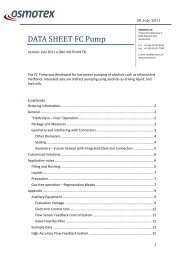
<strong>DATA</strong> <strong>SHEET</strong> <strong>LS</strong> <strong>Basic</strong><br />
<strong>Micropump</strong><br />
Version: July 2011 (Ref. M239)<br />
29 July 2011<br />
OSMOTEX AG<br />
Untere Gründlistrasse 1<br />
6055 Alpnach Dorf<br />
Switzerland<br />
Tel. +41 (0) 41 672 9140<br />
Fax +41 (0) 41 672 7500<br />
E.mail: info@osmotex.ch<br />
www.osmotex.ch<br />
Like other <strong>Osmotex</strong> micropumps, this product has the advantage of small size, high<br />
performance and low power. Being the simplest version offered, it does not include<br />
provisions for suppressing bubble-formation and electrolysis. It requires an open<br />
inlet reservoir, and will also leave gas bubbles in the flow path under typical<br />
circumstances (low voltage pumping of ethanol can be an exception). It can be used<br />
with DI water, a range of buffers and ionic solutions as well as with some alcohols.<br />
Contents<br />
Ordering Information ..................................................................................................... 2<br />
General ........................................................................................................................... 2<br />
Typical Performance – <strong>LS</strong> <strong>Basic</strong> <strong>Micropump</strong> .............................................................. 2<br />
Package and Measures .............................................................................................. 3<br />
Geometry and Interfacing with Connectors .............................................................. 4<br />
Other Diameters .................................................................................................... 5<br />
Sealing .................................................................................................................... 5<br />
Geometry – Future Version with Integrated Electrical Connectors ...................... 6<br />
Application notes ........................................................................................................... 7<br />
Filling and Flushing ..................................................................................................... 7<br />
Liquids ........................................................................................................................ 7<br />
Precaution .................................................................................................................. 7<br />
Customized Solutions ..................................................................................................... 8<br />
Appendix ........................................................................................................................ 9<br />
Auxiliary Equipment ................................................................................................... 9<br />
Evaluation Package ................................................................................................ 9<br />
Example Data for DI water ....................................................................................... 11<br />
1
Ordering Information<br />
For orders, please contact:<br />
<strong>Osmotex</strong> AG<br />
Untere Gründlistrasse 1<br />
6055 Aplnach Dorf<br />
Switzerland<br />
Tel: +41 41 672 9140 / 41<br />
Fax: +41 41 672 75 00<br />
Info@<strong>Osmotex</strong>.ch<br />
General<br />
<strong>Osmotex</strong>’ electroosmotic (EO) pumps have the following advantages:<br />
29 July 2011<br />
� Very compact disc-shaped design, typical dimensions Ø15mm, thickness 2-<br />
4mm<br />
� Do not create gas bubbles in flow path given a certain counter pressure<br />
(some versions)<br />
� Reduced influence of electrochemistry<br />
� Low power<br />
� Silent<br />
� Low cost, suitable for volume applications<br />
<strong>Osmotex</strong> develops advanced EO pumps with strongly reduced influence of<br />
electrochemistry and bubble formation, when used in the correct way.<br />
Electrochemical reactions should still be considered when considering new liquids.<br />
While <strong>Osmotex</strong>’ standard products cover a wide range of power, flow rates, liquids<br />
and other conditions, <strong>Osmotex</strong> can also develop customized solutions when needed.<br />
Standard pumps are delivered un-calibrated. Like for other EO pumps, the flow –<br />
pressure – voltage characteristics depends on the liquid used. <strong>Osmotex</strong> also offers<br />
robust solutions with flow-sensor feedback control.<br />
Typical Performance – <strong>LS</strong> <strong>Basic</strong> <strong>Micropump</strong><br />
Operating voltage 0 – 15 V<br />
Flow rate ca 10 - 150 µl/min<br />
Pressure up to at least 10 PSI (0.7 bar)<br />
Power consumption: from a few mW up to a few 100 mW (varies across the wide<br />
range of performance settings and liquids). Note that flow rate and pressures are<br />
liquid dependent for electroosmotic pumps.<br />
Flow direction: towards negative electrode.<br />
2
29 July 2011<br />
Figure 1: Typical flow-pressure characteristics, curves for 5, 6, 7, 8, 9, 10, 11 and 15<br />
V DC from left to right (fluid: DI water).<br />
Package and Measures<br />
Shape: Circular disc<br />
Diameter: 14 mm<br />
Thickness: 1.8 mm<br />
Despite different characteristics, all <strong>Osmotex</strong> micropumps are embedded in the<br />
same type compact plastic package. These “Pump Cores” (figure 2) do not include<br />
fluidic and electric connectors, but can be interfaced with various lab-chips,<br />
connectors and other equipment.<br />
<strong>Osmotex</strong> also offers an evaluation package with fluidic and electric connectors (see<br />
Appendix).<br />
3
29 July 2011<br />
Figure 2: <strong>Osmotex</strong> micropump “Core”. The liquid flow generated is perpendicular<br />
to the clover-shaped area in the disc center.<br />
Geometry and Interfacing with Connectors<br />
In the following is included information necessary to design fluidic and electrical<br />
connectors. The clover shaped area in the centre must be available for liquid flow,<br />
while the area around can be used for sealing. For example, a flat rubber gasket with<br />
diameter large enough to encircle the clover can be pressed against the Pump Core.<br />
Figure 3: Top/bottom view.<br />
4
Figure 4: Side view.<br />
29 July 2011<br />
Other Diameters<br />
The standard version has electrode diameter 6mm (open flow diameter 5 mm as<br />
shown on figure). <strong>Osmotex</strong> also offer versions with diameters 4 and 8 mm, with<br />
maximum flow rates approximately half and double that of the standard version,<br />
respectively.<br />
Sealing<br />
The micropump can be interfaced with fluidic connectors using a gasket, for example<br />
made of a rubber such as NBR, FKM or (for less deformation) EPDM. It is important<br />
that the rubber does not block the gas venting holes and that the gass is allowed to<br />
pass to the atmosphere.<br />
5
29 July 2011<br />
Geometry – Future Version with Integrated Electrical<br />
Connectors<br />
<strong>Osmotex</strong> plans to launch a version of the micropump with electric connectors on the<br />
top face of the disc shaped Pump Core. This will provide a more compact design<br />
without leads sticking out from the periphery. The exact measures of the product<br />
might differ from the provisional measures presented in this section.<br />
Figure 5: Top view, integrated connectors (provisional measures).<br />
Figure 6: Side view, integrated connectors (provisional measures).<br />
Figure 7: Bottom view, integrated connectors (provisional measures).<br />
6
Application notes<br />
29 July 2011<br />
Filling and Flushing<br />
The pump can be primed by using a syringe while taking care not to inject air to the<br />
pump or applying excessive pressure.<br />
To obtain stable flow, there should be a constant water level in the inlet reservoir.<br />
NB Electroosmotic pumps cannot suck air and are not self priming.<br />
Liquids<br />
The <strong>LS</strong> <strong>Basic</strong> pump has been tested with DI water, 0.5x TBE buffer, methanol and<br />
ethanol. It should be compatible with many other ionic solutions and polar organic<br />
fluids, although possible electrochemical reactions should be taken into account.<br />
Precaution<br />
The pump should not be run at higher voltages than 15 V (20V for low conductivity<br />
liquids such as ethanol, methanol) and should never be allowed to run dry, as this<br />
could lead to breakdown of the electrodes and porous pump structure.<br />
7
29 July 2011<br />
Customized Solutions<br />
<strong>Osmotex</strong> can engage in application specific development for producers of end user<br />
equipment. Our broad expertise in electrokinetics and microfluidics makes us ready<br />
to meet most challenges, whether the need is a simple pump with package, a robust<br />
design with flow rate feedback control, or the integration of several<br />
pumps on a chip.<br />
<strong>Osmotex</strong> also developed a solution for flow-feedback control for high precision, see<br />
figure 8.<br />
Figure 8: Flow sensor and high precision flow with feedback loop.<br />
8
Appendix<br />
Auxiliary Equipment<br />
Evaluation Package<br />
<strong>Osmotex</strong> can deliver the <strong>LS</strong> <strong>Basic</strong> micropump embedded in an open reservoir<br />
evaluation package with standard fluidic and electrical connectors.<br />
Figure 9: <strong>Osmotex</strong> open reservoir connector.<br />
29 July 2011<br />
Figure 10: Open reservoir connector, bottom view. The fluidic connector has inner<br />
diameter 1.7 mm and outer 2.5 mm.<br />
9
29 July 2011<br />
Figure 11: <strong>Osmotex</strong>’ open reservoir connector would fit into a cylinder as shown<br />
(top and side views).<br />
10
Figure 12: Electrical connector at open reservoir connector.<br />
Example Data for DI water<br />
29 July 2011<br />
Figure 13: Flow-pressure plot at ca 8 V DC. Each spike represents a bubble passing<br />
the flow sensor<br />
11