

Highly Efficient Vertical Axis Wind Turbine for Low-Moderate Speed ...
Highly Efficient Vertical Axis Wind Turbine for Low-Moderate Speed ...
Highly Efficient Vertical Axis Wind Turbine for Low-Moderate Speed ...

You also want an ePaper? Increase the reach of your titles
YUMPU automatically turns print PDFs into web optimized ePapers that Google loves.
<strong>Highly</strong> <strong>Efficient</strong> <strong>Vertical</strong> <strong>Axis</strong> <strong>Wind</strong> <strong>Turbine</strong> <strong>for</strong><br />
<strong>Low</strong>-<strong>Moderate</strong> <strong>Speed</strong> <strong>Wind</strong><br />
Farhang Pourboghrat, Professor<br />
Mechanical Engineering Department<br />
Indo-US Research in Renewable Energy<br />
Symposium on Bio-fuels & <strong>Wind</strong> Energy, 7 th & 8 th December, 2010, New Delhi, India
Presentation Outline<br />
Introduction & Motivations<br />
MSU <strong>Wind</strong> Energy Research Team<br />
Design of <strong>Highly</strong> <strong>Efficient</strong> VAWT<br />
Continuous Variable Transmission (CVT)<br />
Blade Materials and Manufacturing<br />
Testing of FRP Composites<br />
FEA of FRP Composite Forming<br />
..<br />
Ideas <strong>for</strong> Collaboration
Motivating Factors:<br />
Introduction<br />
Reduce Dependence on Petroleum to Generate Electricity<br />
Generate Electricity From Clean, Renewable <strong>Wind</strong><br />
US Statistics:<br />
Total US Electric Capacity in 2007 – 1 TW<br />
Available Resources From <strong>Wind</strong> in the US – 5.5 TW<br />
Generation of Electricity From <strong>Wind</strong> - 2% of Total US<br />
Energy<br />
DOE Goal <strong>for</strong> Generating Electricity From <strong>Wind</strong> By 2030 -<br />
20%<br />
Prevalent Type of <strong>Wind</strong> <strong>Turbine</strong> in the US – HAWT<br />
HAWTs Generate kWatt-MWatt Range of Power<br />
VAWTs Generate Watt-kWatt Range of Power<br />
VAWTs Are Rated to Be Less <strong>Efficient</strong> Than HAWTs
World <strong>Wind</strong> Map
US <strong>Wind</strong> Map
Michigan <strong>Wind</strong> Map<br />
MSU
NREL Chart of Efficiency <strong>for</strong> Various<br />
Types of <strong>Wind</strong> <strong>Turbine</strong>s
Advantages<br />
Disadvantages<br />
Advantages<br />
Disadvantages<br />
VAWT vs. HAWT<br />
Horizontal <strong>Axis</strong> <strong>Wind</strong> <strong>Turbine</strong> (HAWT)<br />
Higher efficiency due to variable blade pitch.<br />
Consistent wind loading over the course of a rotation reduces vibration and noise.<br />
Established manufacturing know-how and market acceptability.<br />
Increased costs of transporting tall towers and long blades.<br />
Installation requires very tall and expensive cranes and skilled operators.<br />
Massive tower and heavy foundation to support blades, gearbox, and generator.<br />
Complex design of twisted blades is difficult and expensive to fabricate.<br />
Large size may disrupt the landscape and create local opposition.<br />
Requires yaw control to turn the blades and nacelle toward the wind.<br />
A distance of 5 rotor diameters siting is needed in order to minimize wake effects.<br />
Difficult, expensive, and frequent maintenance required.<br />
<strong>Vertical</strong> <strong>Axis</strong> <strong>Wind</strong> <strong>Turbine</strong> (VAWT)<br />
Smaller tower structure, since lower bearings are mounted near the ground.<br />
The generator and gearbox are installed near the ground.<br />
Suitable <strong>for</strong> low speed winds, due to lower wind startup speed.<br />
May be built at locations where taller structures are prohibited.<br />
Can take advantage of locations where landscape increases wind speed near the ground.<br />
May have a lower noise signature.<br />
Needs less space than HAWT to generate the same amount of power.<br />
Straight blades are much easier and economical to fabricate or extrude.<br />
<strong>Low</strong>er overall maintenance and transportation costs.<br />
<strong>Low</strong>er aerodynamic efficiency compared to HAWT.<br />
Blade fatigue failure due to change in stress sign during each revolution.<br />
May require dismantling the entire structure to fix the generator or gearbox.
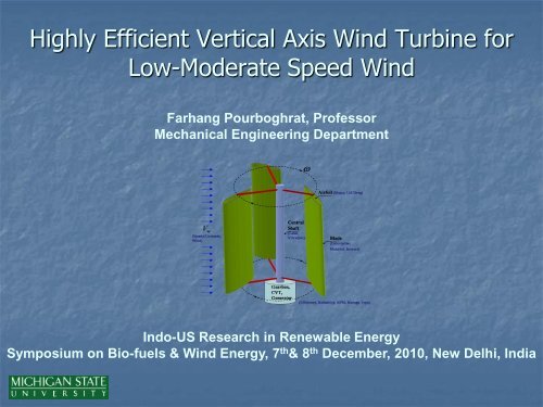
GOAL: Develop Lighter, Stronger, Reliable,<br />
<strong>Highly</strong> <strong>Efficient</strong> Straight-Blade VAWT<br />
V<br />
w<br />
(Steady/Unsteady,<br />
<strong>Low</strong> <strong>Speed</strong> <strong>Wind</strong>)<br />
Blade Orientation<br />
Mechanism<br />
Central<br />
Shaft<br />
(Load,<br />
Vibration)<br />
Gearbox, CVT<br />
Electric<br />
Generator<br />
(Optimum Tip<br />
Velocity Ratio)<br />
Airfoil<br />
(Shape,<br />
Lift/Drag)<br />
Blade<br />
(Orientation,<br />
Material,<br />
Sensors)<br />
(Efficiency, Reliability,<br />
RPM, Storage Type)
Industrial Partners<br />
MSU<br />
<strong>Wind</strong><br />
Energy<br />
Team<br />
University and<br />
Research Lab<br />
Partners<br />
Develop <strong>Efficient</strong>, and<br />
Reliable Transmission<br />
Systems, Including CVT <strong>for</strong><br />
Variable <strong>Wind</strong> Conditions<br />
Pourboghrat, Feeney
On-Going Projects..<br />
Experimental Research <strong>Wind</strong> <strong>Turbine</strong> (W/T):<br />
The W/T is Comprised of a Variable <strong>Speed</strong> Motor to<br />
Simulate Variable <strong>Wind</strong> Conditions; a CVT; an<br />
Induction Generator; and a Battery.<br />
The Set Up Will be Used to Verify Computational<br />
Modeling.<br />
The CVT will Control RPM and Tip <strong>Speed</strong> Ratio (TSR),<br />
to Insure that Generator’s Output Remains at 60 Hz.<br />
Lightweight Composite Blades Will be Added Later.<br />
Developing a FAST/Simulink Model of W/T with CVT to<br />
Optimize Power Output and Mitigate Vibration Loads.<br />
Pressure Sensors <strong>for</strong> Real Time Monitoring of Blades.<br />
Finite Element Analysis of Vibration Loads in Gear Train<br />
Systems (Using Romax software)..<br />
Fabricating a High Efficiency VAWT with Blade Pitch<br />
Control Mechanism.
Grid<br />
t<br />
g<br />
Air<br />
<strong>Wind</strong> <strong>Turbine</strong>:<br />
1<br />
2<br />
3<br />
Power t g Air CP V A<br />
Drivetrain Efficiency<br />
Generator Efficiency<br />
AirDenisty 1.2 Kg m<br />
C Power Coefficient ( Betz Limit, Max 0.59)<br />
P<br />
50 Hz<br />
Inverter<br />
Asynchronous<br />
Generator<br />
3<br />
Fixed<br />
Gear<br />
Problem Areas<br />
Rotor<br />
V D<br />
D Rotor Diameter m<br />
V <strong>Wind</strong> Velocity m s<br />
1 2 2<br />
A Sweep Area D ( m )<br />
4
Grid<br />
60 Hz<br />
1. <strong>Wind</strong> <strong>Turbine</strong> with CVT<br />
NuVinci CVT<br />
Inverter<br />
Asynchronous<br />
Generator<br />
Variable<br />
Gear<br />
(CVT)<br />
BENEFITS:<br />
•Maximum efficiency even with sudden changes in wind speed.<br />
• The generator produces electric current at a constant frequency.<br />
• Improved output, efficiency, and reduced vibrations.<br />
Fixed<br />
Gear<br />
Rotor<br />
V D
NuVinci CVT
Experimental Set Up Representing W/T<br />
Motor<br />
Controller<br />
CVT<br />
• NuVinci CVT gear ratios range between 0.5:1.75 (350%)<br />
• The CVT will control the “tip-speed ratio” <strong>for</strong> optimum W/T per<strong>for</strong>mance.<br />
V T<br />
V<br />
“tip-speed ratio”: . D 2V<br />
V<br />
D .<br />
2<br />
Generator
PID Control of HAWT + CVT with FAST/Simulink*<br />
The control objective is to track the ideal tip-speed ratio.<br />
Simulation of the system’s per<strong>for</strong>mance in response to five turbulent wind<br />
conditions show an improvement in the electric energy output compared with<br />
the standard fixed-speed operation ranging from 3.9% to 29.8%.<br />
A mitigation of fatigue loading is also possible but not done.<br />
Control scheme can be optimized to take full advantage of CVT capabilities.<br />
*Andrew H. Rex and Kathryn E. Johnson, Journal of Solar Energy Engineering, 2009.
FAST/Simulink Modeling of HAWT/VAWT with CVT<br />
Rotor<br />
Gear<br />
train<br />
CVT<br />
Aerodynamics Dynamics Dynamics &<br />
Controls<br />
Apply SISO/MIMO Controls Strategies to<br />
both mitigate load and improve efficiency<br />
Simulink®<br />
Induction<br />
Generator<br />
Electromagnetics
Objective<br />
2. Nonlinear Dynamic Loading and Responses <strong>for</strong><br />
<strong>Wind</strong> <strong>Turbine</strong> Reliability<br />
Brian Feeny, Michigan State University, Award # CBET-0933292<br />
Understanding of wind turbine blade<br />
dynamics, and how dynamic loading<br />
affects gearbox reliability.<br />
Issues<br />
• Cyclic gravitational <strong>for</strong>ce F<br />
• Direct cyclic component<br />
• Parametric cyclic component<br />
• Aerodynamic <strong>for</strong>ces (e.g. distributed f a)<br />
• Cyclic via wind shear, shadowing<br />
• Self excitation (flutter)<br />
• Responses cause gearbox loadings<br />
Collaboration: MSU, Romax Tech., NREL<br />
Gearbox Reliability Collaborative. Modal<br />
analysis of gearbox housing. FEM of<br />
gearbox, under vibration loading.<br />
f a<br />
F p<br />
F d<br />
F = mg<br />
wind
Nonlinear Dynamic Loading and Responses <strong>for</strong><br />
<strong>Wind</strong> <strong>Turbine</strong> Reliability<br />
Brian Feeny, Michigan State University, Award # CBET-0933292<br />
Loaded Romax Model:<br />
NREL Gearbox<br />
HS<br />
LS<br />
Contact stress, outer race HS<br />
shaft bearing<br />
FEM Modal Analysis on<br />
Housing<br />
Contact stress, HS shaft<br />
pinion gear tooth
3. Blade Material Options<br />
Light Weight, Strong, Impact Resistant, Durable, Inexpensive<br />
Matrix Choices:<br />
Thermoplastic (Polypropylene, Polyethylene,..)<br />
Thermoset (Polyester,..)<br />
Biobased (Polyurethane, PLA, PHBV,..)<br />
Non-Renewable Fiber Rein<strong>for</strong>cement Choices:<br />
Glass and Carbon Fibers<br />
Hybrid of Glass/Carbon Fibers (applied to select areas)<br />
Graphene nano-platelets<br />
Renewable Fiber Rein<strong>for</strong>cement Choices:<br />
Straw Bio-Fibers (Corn/Wheat/Rice)<br />
Non-Wood Bio-Fibers (Kenaf/Sisel/Henequen/Coir)<br />
Wood Bio-Fibers<br />
Nano-Whiskers
E (BTUs)/1 lb. fiber<br />
U.S. Cents/lb.<br />
120<br />
100<br />
80<br />
60<br />
40<br />
20<br />
0<br />
30,000<br />
25,000<br />
20,000<br />
15,000<br />
10,000<br />
5,000<br />
0<br />
Why Bio Fibers <strong>for</strong> Blades?<br />
Cost comparison<br />
70<br />
23,500<br />
Energy savings<br />
6,500<br />
Glass Kenaf<br />
- Mechanical PERFORMANCE<br />
- Biodegradable and Recyclable<br />
- CO 2 Neutral & Sequesterization<br />
25<br />
Glass Biofiber<br />
Density, g/cm3<br />
4<br />
3<br />
2<br />
1<br />
0<br />
2.6<br />
Weight savings<br />
1.3<br />
Glass Biofiber<br />
Biodegradable<br />
Materials
Specific Modulus (E-Modulus/Density)<br />
60<br />
50<br />
40<br />
30<br />
20<br />
10<br />
0<br />
Comparison of Specific Modulus <strong>for</strong> Various<br />
Fibers<br />
Kenaf<br />
Hemp<br />
Modulus/Cost<br />
Comparison<br />
1 Sisal Coir E-Glass<br />
Modulus/Cost (E-Modulus/($/kg))<br />
160<br />
140<br />
120<br />
100<br />
80<br />
60<br />
40<br />
20<br />
0<br />
Mechanical<br />
Per<strong>for</strong>mance:<br />
Modulus<br />
Comparison<br />
Comparison of Modulus Per Cost <strong>for</strong> Various<br />
Fibers<br />
1<br />
Kenaf Sisal Coir E-Glass<br />
Ref.: Zampaloni, M., Pourboghrat, F., Yankovich, S. A., Rodgers, B. N., James Moore, Misra, M.,<br />
Mohanty, A. K., and Drzal, L. T., Composite A, 2007
Flexural Strength (MPa)<br />
80<br />
40<br />
0<br />
Flex Strength (MPa)<br />
Flex Modulus (GPa)<br />
34<br />
46<br />
1.7 1.5<br />
Ref.: A. K. Mohanty, S. Desai, P.<br />
Mulukutla, M. Misra, L. T. Drzal, 2004<br />
6.2<br />
37<br />
PHB PP PHB + 30%<br />
KENAF<br />
Impact<br />
Strength<br />
PHB +30% Kenaf<br />
superior to PP +<br />
30%Glass<br />
35<br />
3.5<br />
36<br />
3.8<br />
Impact Strength (J/m)<br />
80<br />
70<br />
60<br />
50<br />
40<br />
30<br />
20<br />
10<br />
0<br />
67<br />
5.4<br />
Kenaf HENQ Glass<br />
PHB +<br />
30% HENQ<br />
PHB +<br />
30% PALF<br />
PP + 30%<br />
GLASS<br />
24<br />
5.8<br />
35<br />
PHB + 30%<br />
GLASS<br />
9<br />
6<br />
3<br />
0<br />
PHB+ 30%Henequen<br />
comparable to PP+30%Glass<br />
48<br />
36<br />
PHB PP PHB + 30%<br />
KENAF<br />
Flexural Modulus (GPa)<br />
Natural Fibers +<br />
Biocomposites:<br />
58<br />
Kenaf HENQ<br />
PHB + 30%<br />
HENQ<br />
Flexural<br />
Modulus<br />
29<br />
PHB +<br />
30%PALF<br />
65<br />
Glass<br />
PP + 30%<br />
GLASS<br />
46<br />
PHB + 30%<br />
GLASS
Effect of Fiber Length and Volume Fraction:<br />
Modulus (MPa)<br />
12<br />
9<br />
6<br />
3<br />
0<br />
2.9<br />
3<br />
4.6<br />
5.9<br />
6.2<br />
A B C D E F<br />
11<br />
A= 30% kenaf 6mm fiber/ soy composites injection molding<br />
B= 33% Kenaf 6mm fiber/ soy compression molding<br />
C= 55% Kenaf 2mm fiber/ soy compression molding<br />
D= 56% Kenaf 6mm fiber/ soy compression molding<br />
E= 57% Kenaf 2 inch fiber /soy compression molding<br />
F= 54% Kenaf long fiber/ soy compression molding<br />
Impact strength (J/m)<br />
400<br />
350<br />
300<br />
250<br />
200<br />
150<br />
100<br />
50<br />
0<br />
Impact strength<br />
Fiber length on impact surface<br />
50<br />
0.2<br />
92<br />
0.8<br />
125<br />
0.7<br />
184<br />
1.2<br />
289<br />
2.0<br />
A B C D E F<br />
370<br />
2.7<br />
3<br />
2.5<br />
2<br />
1.5<br />
1<br />
0.5<br />
0<br />
Fiber length on Impact<br />
surface (mm)
CNT Nanoparticle<br />
Modification of CF<br />
Surface<br />
CNT - high modulus, high strength,<br />
high electrical conductivity etc.<br />
Expected CFRP properties<br />
a. Fiber direction<br />
- tensile strength<br />
- compressive strength (-> OHC)<br />
b. Transverse direction<br />
- interlaminar fracture toughness (-><br />
CAI)<br />
- electrical conductivities<br />
(-> lightning striking resistance)<br />
c. Others<br />
- damping property<br />
Additional Improvements:<br />
Exfoliated graphene Nanoplatelets at 5wt%<br />
functionalized with a CTBN toughening agent increased<br />
the unnotched impact strength by 238% of the base<br />
vinyl ester resin without any loss of modulus.<br />
MWCNT at 0.5 wt% coated on the CF surface increased<br />
the Mode II fracture toughness by 7% without loss of<br />
modulus or strength.<br />
Compressive strength<br />
CF CNT<br />
preventing fiber buckling by<br />
enhancement of modulus<br />
and yield strength of matrix<br />
Interlaminar fracture toughness<br />
stopping crack propagation<br />
by bridging effect
[MPa] [MPa] [MPa]<br />
[MPa] [MPa] [MPa] [MPa]<br />
200<br />
180<br />
160<br />
140<br />
120<br />
100<br />
80<br />
60<br />
40<br />
20<br />
14000<br />
12000<br />
10000<br />
6000<br />
4000<br />
Flexural Strength<br />
0<br />
0 5 10 15<br />
[Vol%]<br />
20 25 30<br />
Flexural Modulus<br />
Flexural Modulus Of<br />
1um Graphite<br />
Nylon 66 15um Rein<strong>for</strong>ced<br />
Graphite<br />
In-situ<br />
CF<br />
With Up VGCF To 20 v%<br />
CB<br />
8000 Nanofillers.<br />
Flexural Modulus<br />
[MPa]<br />
14000<br />
12000<br />
10000<br />
8000<br />
6000<br />
4000<br />
2000<br />
0<br />
1um Graphite<br />
15um Graphite<br />
In-situ<br />
CF<br />
VGCF<br />
CB<br />
Flexural Modulus<br />
1um Graphite<br />
15um Graphite<br />
In-situ<br />
CF<br />
VGCF<br />
CB<br />
Flexural Strength Of<br />
Nylon 66 Rein<strong>for</strong>ced<br />
With Up To 20 v%<br />
Nanofillers.<br />
Flexural Modulus<br />
0 5 10 15 20 25<br />
[Vol%]
4. Experimental Testing of FRP Laminate<br />
Glass mat fiber rein<strong>for</strong>ced thermoplastic<br />
Continuous fiber rein<strong>for</strong>cement (40% glass)<br />
Long, chopped fiber rein<strong>for</strong>cement (32% glass)<br />
“long” -> 50-100 mm in length<br />
Polypropylene resin matrix<br />
Processing at 0-30 psi Pressure
Glass Mat<br />
207 kPa (30 psi)<br />
0 kPa<br />
Glass Mat<br />
Delamination
Squeeze Flow Test –<br />
A Method to Measure Anisotropy<br />
Metal Plates<br />
Preferred fiber orientation determination<br />
Fiber Rein<strong>for</strong>ced Sample<br />
Heated Platens
Distance from center (in)<br />
4.2<br />
4.1<br />
4<br />
3.9<br />
3.8<br />
3.7<br />
3.6<br />
3.5<br />
3.4<br />
3.3<br />
3.2<br />
3.1<br />
3<br />
Determining the Preferred Fiber Orientations from Compression Tests <strong>for</strong> R401-B01<br />
0 20 40 60 80 100 120 140 160 180 200 220 240 260 280 300 320 340 360<br />
Angle along part (deg)<br />
Chopped Fiber<br />
Length (in)<br />
4<br />
3.75<br />
3.5<br />
3.25<br />
3<br />
2.75<br />
2.5<br />
Continuous Fiber<br />
Determining the Preferred Fiber Orientations using the Distance from the<br />
Center Point after Compression Testing <strong>for</strong> C321- Chopped Fiber Mat<br />
0 20 40 60 80 100 120 140 160 180 200 220 240 260 280 300 320 340 360<br />
Degrees from Zero (deg)
Stress (kPa)<br />
140000<br />
120000<br />
100000<br />
80000<br />
60000<br />
40000<br />
20000<br />
0<br />
Stress-Strain Curve <strong>for</strong> R401-B01, Continuous Fiber Mat, 60 Degree Direction<br />
Ef = 6.95 Gpa (1008 ksi)<br />
0 0.01 0.02 0.03 0.04 0.05 0.06 0.07 0.08 0.09 0.1 0.11 0.12 0.13<br />
Strain (mm/mm)<br />
Stress-Strain Curve<br />
<strong>for</strong> a sample along<br />
the 30 o Direction<br />
Stress (kPa)<br />
60000<br />
50000<br />
40000<br />
30000<br />
20000<br />
10000<br />
0<br />
Uniaxial Tension Test Specimen<br />
Stress-Strain Curve<br />
<strong>for</strong> a sample along<br />
the 60 o Direction<br />
Stress-Strain Plot <strong>for</strong> C321-B01, Chopped Fiber Mat Thermoplastic,<br />
30 Degree Direction<br />
E f = 3.56 Gpa (516 ksi)<br />
0 0.01 0.02 0.03 0.04 0.05 0.06 0.07 0.08 0.09 0.1 0.11<br />
Strain (mm/mm)
5. Finite Element Modeling of FRP<br />
Initial<br />
configuration<br />
Final<br />
configuration
Constitutive Relationship <strong>for</strong><br />
Multiple Preferred Fiber<br />
Multiple Preferred<br />
Fiber Orientations<br />
Orientations<br />
1-Fiber<br />
Direction<br />
2-Fiber<br />
Direction<br />
t 1 2<br />
...<br />
n<br />
jk jk jk jk<br />
Q Q Q Q<br />
Q<br />
t<br />
jk<br />
3-Fiber<br />
Direction<br />
Stresses and Strains based on rotated material frame<br />
n-Fiber<br />
Directions
Components of the Stiffness<br />
Q E<br />
Matrix<br />
11 11 12 21<br />
Q E<br />
22 22 12 21<br />
Q E<br />
12 12 11 12 21<br />
Q G<br />
33 12<br />
13 31 23 32<br />
21 12<br />
/(1 )<br />
/(1 )<br />
/(1 )<br />
Q Q Q Q<br />
Q Q<br />
Material properties defined along the fiber directions<br />
0
Material Properties Needed as<br />
Model Input<br />
Input parameters<br />
Young’s modulus of the fiber (E f)<br />
Young’s modulus of the resin (E m)<br />
Poisson’s ratio <strong>for</strong> the fiber ( f)<br />
Poisson’s ratio <strong>for</strong> the resin ( m)<br />
Shear modulus <strong>for</strong> the fiber (G f)<br />
Shear modulus <strong>for</strong> the resin (G m)<br />
Initial volume fraction (V fo)
Input Parameters <strong>for</strong><br />
Constitutive Model - Glass Fiber<br />
Continuous Fiber Mat Chopped Fiber Mat<br />
E f, 0 5.15 GPa E f, 30 3.56 GPa<br />
E f, 60 6.95 GPa E f, 105 6.5 GPa<br />
E f, 90 6.69 GPa E f, 120 4.9 GPa<br />
E m, all 1.5 GPa E f, 150 3.95 GPa<br />
f, all 0.361 E m, all 1.5 GPa<br />
m, all 0.1 f, all 0.317<br />
G f, all 29.9 GPa m, all 0.1<br />
G m, all 0.2 MPa G f, all 29.9 GPa<br />
G m, all<br />
0.2 MPa
De<strong>for</strong>med Shape<br />
Experiment: U.Mohammed et al., Composites Part A, p.1414, 2000
Continuous Glass Fiber Mat
Pressure Effect (on Fiber Angle)<br />
Without pressure With pressure<br />
Fluid Pressure Reduces Fiber Rotation.
Pressure Effect (on Shape)<br />
Without Fluid Pressure 137 kPa (20 psi)<br />
274 kPa (40 psi) 689 kPa (100 psi)
6. Composite Hydro<strong>for</strong>ming*<br />
Prepregs<br />
Processing Steps:<br />
1. Heat Thermoplastic Sheet (in the die).<br />
2. Close Die, Fluid Fill, Pressurization.<br />
3. Displace Punch, Control Pressure.<br />
4. Cool Punch and Part. Remove Part.<br />
1 2<br />
3 4<br />
* Farhang Pourboghrat, Zampaloni, M., and Benard, A., “Hydro<strong>for</strong>ming of<br />
Composite Materials”, US Patent No. 6,631,630, October 14, 2003.
Woven<br />
Glass<br />
Kenaf<br />
Fiber
7. FRP Composite Blade Manufacturing<br />
1) Design Blade Cross Section (Airfoil) For Maximum Lift:<br />
Vorticity Contours over SD7003 Airfoil as obtained<br />
by Large Eddy Simulation.<br />
2) Split The Blade Into Two Halves (Asymmetric):<br />
Top Half<br />
Bottom Half<br />
VAWT Blade
Blade Manufacturing Process<br />
Stamping Process Stamping Process<br />
(a)<br />
Compression Molded Flat Composite Panel<br />
Stamped Flat Panels Forming; (a) Bottom Half, and (b) Top Half.<br />
Adhesively Glued Halves Form the Blade<br />
(b)
Remove<br />
Mold<br />
Adhesive<br />
Pressurized<br />
Medium<br />
Trim Excess<br />
Material<br />
Adhesive<br />
Hybrid<br />
Thermoplastic<br />
Sandwich Sheet<br />
Final<br />
Blade
VAWT with Lightweight<br />
CFPP Blades
8. Effect of Blade Orientation<br />
Adjustment Strategy During the<br />
Rotation on the Efficiency of VAWT<br />
Table 1. Computed Effect of Blade Orientation Adjustment Strategy on VAWT Efficiency<br />
FREQUENCY OF<br />
BLADE<br />
ORIENTATION<br />
ADJUSTMENT<br />
Every 1/2 o<br />
Every 4 o<br />
Every 8 o<br />
WIND<br />
VELOCITY,<br />
V (M/S)<br />
w<br />
TIP SPEED<br />
RATIO,<br />
R V<br />
w<br />
TORQUE,<br />
T (N.M)<br />
POWER,<br />
(WATT)<br />
P T<br />
EFFICIENCY,<br />
C P P<br />
p wind<br />
5.0 1.0 35.3 176.5 47.5%<br />
7.5 1.0 79.5 596.3 47.5%<br />
5.0 1.0 18.8 94 25.3%<br />
7.5 1.0 42.2 316.5 25.3%<br />
5.0 0.81 6.53 26.4 7.1%<br />
7.5 0.81 14.7 89.1 7.1%
Cascade Model Prediction of Power<br />
Generated by High Efficiency VAWT<br />
with Pitched Blade<br />
Table – Numbers and Sizes of VAWTs Needed to Generate 30 MWh Energy per month<br />
WIND<br />
CATEGORY<br />
AND<br />
LOCATION<br />
HEIGHT<br />
FROM<br />
GROUND,<br />
H (M)<br />
VAWT<br />
DIAMETER,<br />
D, AND<br />
BLADE<br />
HEIGHT, H<br />
(M)<br />
WIND<br />
VELOCITY,<br />
V (M/S)<br />
POWER<br />
(KW)<br />
ENERGY<br />
(MWH/MONTH)<br />
NUMBER<br />
OF WIND<br />
TURBINES<br />
3 (Lansing) 10 10, 12 4.71 3.54 2.55 12<br />
3 (Lansing) 30 10, 12 5.62 6.0 4.32 7<br />
3 (Lansing) 50 10, 12 6.09 7.67 5.52 6<br />
3 (Lansing) 30 16,18 5.62 13.89 10.0 3<br />
3 (Lansing) 50 14,16 6.09 13.89 10.0 3<br />
5 (Shore) 50 14, 16 8.8 41.7 30.0 1<br />
6 (Shore) 50 12, 14 9.6 41.7 30.0 1
Areas of Collaboration<br />
<strong>Wind</strong> Tunnel Testing of Medium Size <strong>Highly</strong> <strong>Efficient</strong> VAWT.<br />
Construction and Field Testing of <strong>Highly</strong> <strong>Efficient</strong> VAWT in <strong>Low</strong>-<strong>Moderate</strong> <strong>Speed</strong><br />
<strong>Wind</strong> Regions.<br />
Scaling Up of the <strong>Highly</strong> <strong>Efficient</strong> VAWT.<br />
Mechanisms <strong>for</strong> Pitching W/T Blades <strong>for</strong> Optimum Per<strong>for</strong>mance.<br />
Blade Shape Morphing Mechanisms, Materials and Related Technologies.<br />
Computational Model Development<br />
Multi-Scale Computational Models to Predict Mechanical, Electrical, Thermal,<br />
Electromagnetic Properties of Nano-Platelet Rein<strong>for</strong>ced Polymer Composites.<br />
Failure Models <strong>for</strong> Nano-Platelet Rein<strong>for</strong>ced Polymer Composites.<br />
Fatigue Failure Models <strong>for</strong> Various <strong>Wind</strong> <strong>Turbine</strong> Components.<br />
Computationally <strong>Efficient</strong> Fluid-Solid Interaction Strategies/Model <strong>for</strong> Blade<br />
Aerodynamics Simulation.<br />
Integration of Simulink with Aerodynamics, Gear Train, CVT, and Generator<br />
Models.<br />
Robust Controls Strategies <strong>for</strong> Optimization of <strong>Wind</strong> <strong>Turbine</strong>s System.<br />
Etc.<br />
Sensor Development <strong>for</strong> Real-Time Health Monitoring of <strong>Wind</strong> <strong>Turbine</strong> System.<br />
Land Policy and Supply Chain Management Issues in India.
Thank You!<br />
Questions?
U.S. <strong>Wind</strong> Map
4. Fabrication of Flat Laminated Composites<br />
(a)<br />
(a)<br />
50 wt % PLA /50 wt % Kenaf fiber mat laminated composite: (a) be<strong>for</strong>e and<br />
(b) after the Compression Molding.<br />
Hybrid laminated composite (PLA/Glass mat/PLA/Kenaf fiber /PLA/Kenaf fiber<br />
/PLA/Glass mat/PLA) : (a) be<strong>for</strong>e and (b) after the Compression Molding.<br />
(b)<br />
(b)