Air conditioning using displacement ventilation to maximize ... - Cibse
Air conditioning using displacement ventilation to maximize ... - Cibse
Air conditioning using displacement ventilation to maximize ... - Cibse

You also want an ePaper? Increase the reach of your titles
YUMPU automatically turns print PDFs into web optimized ePapers that Google loves.
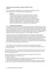
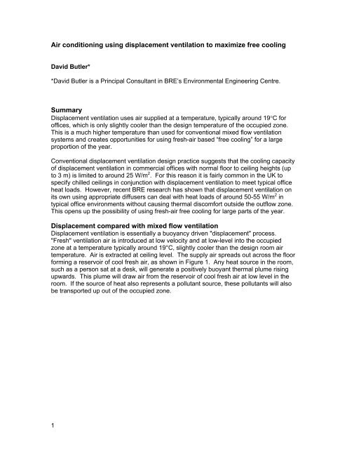
<strong>Air</strong> <strong>conditioning</strong> <strong>using</strong> <strong>displacement</strong> <strong>ventilation</strong> <strong>to</strong> <strong>maximize</strong> free cooling<br />
David Butler*<br />
*David Butler is a Principal Consultant in BRE’s Environmental Engineering Centre.<br />
Summary<br />
Displacement <strong>ventilation</strong> uses air supplied at a temperature, typically around 19°C for<br />
offices, which is only slightly cooler than the design temperature of the occupied zone.<br />
This is a much higher temperature than used for conventional mixed flow <strong>ventilation</strong><br />
systems and creates opportunities for <strong>using</strong> fresh-air based “free cooling” for a large<br />
proportion of the year.<br />
Conventional <strong>displacement</strong> <strong>ventilation</strong> design practice suggests that the cooling capacity<br />
of <strong>displacement</strong> <strong>ventilation</strong> in commercial offices with normal floor <strong>to</strong> ceiling heights (up<br />
<strong>to</strong> 3 m) is limited <strong>to</strong> around 25 W/m 2 . For this reason it is fairly common in the UK <strong>to</strong><br />
specify chilled ceilings in conjunction with <strong>displacement</strong> <strong>ventilation</strong> <strong>to</strong> meet typical office<br />
heat loads. However, recent BRE research has shown that <strong>displacement</strong> <strong>ventilation</strong> on<br />
its own <strong>using</strong> appropriate diffusers can deal with heat loads of around 50-55 W/m 2 in<br />
typical office environments without ca<strong>using</strong> thermal discomfort outside the outflow zone.<br />
This opens up the possibility of <strong>using</strong> fresh-air free cooling for large parts of the year.<br />
Displacement compared with mixed flow <strong>ventilation</strong><br />
Displacement <strong>ventilation</strong> is essentially a buoyancy driven "<strong>displacement</strong>" process.<br />
"Fresh" <strong>ventilation</strong> air is introduced at low velocity and at low-level in<strong>to</strong> the occupied<br />
zone at a temperature typically around 19°C, slightly cooler than the design room air<br />
temperature. <strong>Air</strong> is extracted at ceiling level. The supply air spreads out across the floor<br />
forming a reservoir of cool fresh air, as shown in Figure 1. Any heat source in the room,<br />
such as a person sat at a desk, will generate a positively buoyant thermal plume rising<br />
upwards. This plume will draw air from the reservoir of cool fresh air at low level in the<br />
room. If the source of heat also represents a pollutant source, these pollutants will also<br />
be transported up out of the occupied zone.<br />
1
2<br />
Return grill Return grill<br />
Figure 1 Displacement <strong>ventilation</strong> – typical room air flow<br />
Extensive investigations elsewhere (1-6) have shown that generally two distinct stratified<br />
layers of air form, an upper zone containing warm polluted air and a lower zone<br />
containing cooler cleaner air separated by a boundary layer. This causes a vertical<br />
temperature gradient <strong>to</strong> develop (typically 5-6°C between supply and extract), resulting<br />
in higher temperatures at ceiling level than with standard mixing <strong>ventilation</strong> systems.<br />
Displacement <strong>ventilation</strong> strategies exploit this vertical temperature gradient by<br />
maintaining the lower occupied zone at comfort conditions while allowing the upper<br />
hotter zone <strong>to</strong> increase <strong>to</strong> temperatures in excess of accepted comfort limits. A risk with<br />
such a strategy is, however, that significant vertical temperature gradient between feet<br />
and head height can lead <strong>to</strong> discomfort and this must be considered when designing<br />
such a system.<br />
Mixed flow <strong>ventilation</strong> is essentially a "mixing" process in which stale warm room air is<br />
continually diluted by cooled fresh air. The air in the room is fully mixed and therefore air<br />
temperature and pollutant concentrations are uniform throughout the space. Fresh air is<br />
normally introduced and removed at ceiling level and the interaction of upward warm air<br />
currents and horizontal supply air jets below the ceiling causes mixing and circulation <strong>to</strong><br />
lower areas with relatively high air speeds (see Figure 2). This can lead <strong>to</strong> draughts and<br />
discomfort in the occupied area. Because air is supplied and extracted at ceiling level<br />
some of the supplied ‘fresh’ air may short circuit by being drawn in<strong>to</strong> the extract grilles<br />
which effectively reduces its cooling and pollutant dilution potential.
3<br />
supply grill Return grill<br />
Figure 2 Mixed flow <strong>ventilation</strong> – typical room air flow<br />
The air supply temperature for <strong>displacement</strong> <strong>ventilation</strong> systems is typically 19°C<br />
compared <strong>to</strong> 13°C <strong>to</strong> 14°C for most conventional mixing systems. Figure 3 shows the<br />
variation in room air temperature for “ideal” <strong>displacement</strong> <strong>ventilation</strong> in a typical office<br />
environment compared with mixing <strong>ventilation</strong>. Note that in this example there is<br />
approximately 2°C air temperature pick-up between the supply and room air close <strong>to</strong> the<br />
floor due <strong>to</strong> room air entrainment.<br />
Supply air temperature<br />
= 14 o C<br />
9 o C<br />
<strong>Air</strong> temperature near<br />
head height for seated<br />
occupants = 23 o C<br />
Supply air temperature<br />
= 19 o C<br />
Room & extract air<br />
temperature = 23 o C<br />
7 o C<br />
Mixing<br />
<strong>ventilation</strong><br />
12 14 16 18 20 22 24 26 28 30 o C<br />
Extract air temperature<br />
= 26 o C<br />
Displacement<br />
<strong>ventilation</strong><br />
Figure 3 Supply and extract air temperatures for mixed flow and <strong>displacement</strong><br />
<strong>ventilation</strong> (ideal situation)
“Free cooling” opportunities<br />
Supplying air at 19°C <strong>to</strong> a <strong>displacement</strong> <strong>ventilation</strong> system opens up the possibility of<br />
<strong>using</strong> fresh air “free-cooling” for large parts of the year. “Free cooling” is rather a<br />
misleading term as energy will always be needed for fan (and in some cases pump)<br />
operation. In cold weather a heat reclaim thermal wheel or heat exchanger is essential<br />
in order <strong>to</strong> minimise the need for pre-heating of the fresh-air supply. Where there is a<br />
requirement for dehumidification in warm weather a separate low temperature coil may<br />
be required, possibly in conjunction with heat pipe heat recovery and pre-cooling, or face<br />
and bypass dampers.<br />
A bin analysis of annual outdoor dry bulb temperature allows the potential of fresh air<br />
free-cooling <strong>to</strong> be investigated. Figure 4 shows the number of hours occurrence of<br />
outdoor air temperatures for normal working hours (0700 <strong>to</strong> 1800) during a whole year,<br />
based on the average of the five year period 1976 <strong>to</strong> 1980. The effect of a year with a<br />
hot summer is also shown by plotting hours occurrence for 1976 which had an<br />
exceptionally long hot summer. The data can be interpreted more easily by converting it<br />
<strong>to</strong> an accumulated frequency “s-curve”, shown in Figure 5. This allows the proportion of<br />
the <strong>to</strong>tal hours that were at and below a certain threshold temperature <strong>to</strong> be read directly<br />
from the graph. To take account of heat pick up from the air distribution fan (assumed <strong>to</strong><br />
result in a 1°C rise in the air stream) it is appropriate <strong>to</strong> take 12°C for a conventional<br />
mixing <strong>ventilation</strong> system and 18°C for a <strong>displacement</strong> system. The s-curve therefore<br />
shows that fresh-air free-cooling can be used for 85% of the time for a <strong>displacement</strong><br />
system but only 53% of the time for a conventional mixing <strong>ventilation</strong> system.<br />
4<br />
Total hours occurence<br />
350<br />
300<br />
250<br />
200<br />
150<br />
100<br />
50<br />
0<br />
-8<br />
Five year average, 1976<br />
<strong>to</strong> 1980<br />
-5<br />
-2<br />
1<br />
Dry Bulb T (07:00 - 18:00)<br />
Kew 1976 <strong>to</strong> 1980<br />
4<br />
7<br />
10<br />
13<br />
16<br />
19<br />
22<br />
Dry Bulb Temperature (oC)<br />
Figure 4 Bin analysis of outdoor dry bulb air temperature<br />
25<br />
28<br />
31<br />
34
5<br />
Accumated frequency (% hours occurrence)<br />
110%<br />
100%<br />
90%<br />
80%<br />
70%<br />
60%<br />
50%<br />
40%<br />
30%<br />
20%<br />
10%<br />
0%<br />
85%<br />
53%<br />
Dry bulb temperature (whole year, 0700 <strong>to</strong> 1800 hrs)<br />
12 o C 18 o C<br />
-5 0 5 10 15 20 25 30 35<br />
Dry bulb temperature (oC)<br />
1977 cool summer<br />
1976 hot summer<br />
1976 <strong>to</strong> 1980
Figure 5 S-curves for occurrence of outdoor dry bulb temperatures<br />
Additional s-curves for years with a hot summer (1976) and a cool summer (1977) have<br />
also been plotted. These show that a hot summer would reduce the time that fresh air<br />
can be used for the <strong>displacement</strong> system from 85% <strong>to</strong> about 78% of the time. A cool<br />
summer would increase the proportion of the year that free-cooling is available <strong>to</strong> about<br />
90% of the <strong>to</strong>tal time.<br />
Thermal comfort requirements<br />
Thermal comfort requirements place limitations on the design parameters and the<br />
maximum cooling performance achievable with <strong>displacement</strong> <strong>ventilation</strong>. For sedentary<br />
occupancy such as office work, BS EN ISO 7730:1995 (7) recommends that air velocity<br />
on<strong>to</strong> people should not normally exceed 0.15 <strong>to</strong> 0.2 m/s, depending on air temperature<br />
and turbulence intensity. The maximum ankle <strong>to</strong> head temperature gradient (between<br />
0.1 m and 1.1 m above the floor) should not normally exceed 2°C <strong>to</strong> 3°C in summer.<br />
The dry resultant temperature in the occupied region should also normally be between<br />
23°C and 26°C. For <strong>displacement</strong> <strong>ventilation</strong> systems air velocity is principally a function<br />
of the air supply volumetric flow rate and temperature, and the degree of room air<br />
entrainment at the diffuser. The ankle <strong>to</strong> head temperature gradient is also a function of<br />
the supply air volumetric flow rate and the degree of room air entrainment at the diffuser.<br />
Obtaining higher cooling performance with <strong>displacement</strong> <strong>ventilation</strong><br />
Conventional design practice and BRE investigations suggest <strong>displacement</strong> <strong>ventilation</strong><br />
systems in offices (with floor <strong>to</strong> ceiling heights below 3 m) are limited <strong>to</strong> around 20/25<br />
W/m 2 cooling capacity. To increase cooling capacity either the supply air temperature<br />
has <strong>to</strong> be reduced, or the volumetric air supply rate must be increased. Reducing the air<br />
supply air temperature below the normal 19°C is not an option when the aim is the<br />
maximisation of free-cooling, and could lead <strong>to</strong> unacceptable thermal discomfort in the<br />
ankle region. Raising the volumetric air supply rate allows a 19°C supply air<br />
temperature <strong>to</strong> be maintained, but increases the risk of high air speed in the occupied<br />
space. Fan power and duct sizing will also be increased and therefore a life cycle<br />
analysis of this compared with the reductions in cooling energy must be undertaken as<br />
part of specific system designs.<br />
Types of <strong>displacement</strong> diffuser<br />
A wide range of diffusers can be used for <strong>displacement</strong> <strong>ventilation</strong>, including the<br />
following:<br />
6<br />
• Wall mounted diffusers<br />
• Corner mounted diffusers<br />
• Free-standing "bin" diffusers<br />
• Floor mounted swirl diffusers<br />
• Fabric “sock” diffusers.<br />
Figure 6 shows typical air outflow profiles with these diffusers. Fabric sock diffusers are<br />
not yet widely used and are rare in offices in the UK. Wall, corner and free-standing<br />
diffusers typically consist of a perforated plate with an internal baffle <strong>to</strong> promote even air
discharge through the perforated plate face. The active surface areas are usually quite<br />
large without taking up excessive amounts of floor space.<br />
Floor mounted diffusers can normally provide either vertical or horizontal discharge.<br />
Horizontal discharge is usually used for <strong>displacement</strong> applications and this typically<br />
produces a horizontal circular swirling jet. These diffusers are often 150 mm or 200 mm<br />
diameter. This restricted size leads <strong>to</strong> relatively higher discharge or face velocities than<br />
the other types of diffuser.<br />
7<br />
Corner <strong>displacement</strong><br />
diffuser<br />
Wall mounted<br />
<strong>displacement</strong> diffuser<br />
Free standing “bin”<br />
<strong>displacement</strong> diffuser<br />
Figure 6 Outflow air profiles of typical <strong>displacement</strong> <strong>ventilation</strong> diffusers<br />
Floor mounted swirl<br />
<strong>displacement</strong> diffuser<br />
Floor diffusers appear <strong>to</strong> be a very popular choice for new commercial office buildings,<br />
despite the fact that their relative small size conflicts with the <strong>displacement</strong> <strong>ventilation</strong><br />
requirement for air <strong>to</strong> be introduced at low velocity. Their apparent popularity may be<br />
due <strong>to</strong> the installation flexibility offered by floor terminals in conjunction with raised floors,
although there is a risk of low level thermal discomfort if occupants sit <strong>to</strong>o close <strong>to</strong> them.<br />
Limitations of conventional <strong>displacement</strong> diffusers<br />
The primary limitation of <strong>displacement</strong> <strong>ventilation</strong> in dealing with heat loads has been<br />
shown <strong>to</strong> be the amount of air that can be supplied through conventional wall or floor<br />
mounted <strong>displacement</strong> diffusers without ca<strong>using</strong> discomfort due <strong>to</strong> draughts.<br />
The design procedure for the specification of <strong>displacement</strong> <strong>ventilation</strong> diffusers generally<br />
involves defining the distance from the diffuser at which the air speed has decreased <strong>to</strong><br />
between 0.15 and 0.2 m/s (the usual threshold for acceptable thermal comfort), and may<br />
be measured at around 0.1 m above the floor.<br />
BRE has tested a range of conventional <strong>displacement</strong> <strong>ventilation</strong> diffusers including a<br />
swirl <strong>displacement</strong> diffuser and a floor-standing “bin” diffuser. The swirl diffuser had an<br />
active area of 0.125 m 2 (overall diameter = 0.25 m) at a range of air supply volumetric<br />
rates. The results for air speed at 1.07 m from the center of the diffuser are shown in<br />
Figure 7. This shows that the diffuser air supply limit for acceptable thermal comfort<br />
(maximum air speed of 0.15 m/s at 1.07 m from the diffuser and 0.05m above the floor)<br />
is about 30 l/s. Assuming that the diffuser is installed in a space with 3.0 m spacing<br />
between diffusers (9 m 2 floor area per diffuser) and a supply and extract air differential of<br />
6°C (19°C air supply, 25°C extract and about 24°C in the occupied region) the cooling<br />
performance would be 24 W/m 2 .<br />
8<br />
Height (m)<br />
0.30<br />
0.25<br />
0.20<br />
0.15<br />
0.10<br />
0.05<br />
Variation of mean air speed with height at 1.07 m from centre of diffuser<br />
(0.25 m dia floor swirl)<br />
maximum air<br />
speed for<br />
acceptable<br />
thermal comfort<br />
Diffuser A, 10 l/s<br />
Diffuser A, 30 l/s<br />
Diffuser A, 50 l/s<br />
0.00<br />
0.00 0.05 0.10 0.15 0.20<br />
Mean air speed (m/s)<br />
0.25 0.30 0.35 0.40<br />
Figure 7 Swirl diffuser – air speed at 1.07 m from diffuser centre (0.05 m above the<br />
floor)
The bin diffuser was constructed from perforated steel plate and had a height of 0.61 m<br />
and a diameter of 0.20 m, giving an active face area of 0.38 m 2 . Figure 8 shows air<br />
speed at a distance of 1.07 m from the center of the diffuser for a range of air volumetric<br />
supply rates. It is clear that for acceptable thermal comfort (based on air speed in the<br />
space at 0.05 m above the floor) the limit of this diffuser is 50 l/s. It is very unlikely that<br />
in a commercial office space free-standing diffusers could be as close as the 3 m<br />
spacing assumed for the swirl diffusers. Assuming a wider spacing of 4 m and the same<br />
assumptions for air temperatures as for the swirl diffuser the limit on cooling<br />
performance is about 20 W/m 2 . Larger free-standing diffusers would allow higher air<br />
volume supply rates and therefore provide a higher cooling performance than this but<br />
would take up greater floor area.<br />
9<br />
Height (m)<br />
0.30<br />
0.25<br />
0.20<br />
0.15<br />
0.10<br />
0.05<br />
Variation of mean air speed with height at 1.07 m from centre of diffuser<br />
(0.61 m (h) x 0.2 (d) "bin" diffuser)<br />
maximum air<br />
speed for<br />
acceptable<br />
thermal comfort<br />
Diffuser C, 30 l/s<br />
Diffuser C, 50 l/s<br />
Diffuser C, 100 l/s<br />
0.00<br />
0.00 0.05 0.10 0.15 0.20<br />
Mean air speed (m/s)<br />
0.25 0.30 0.35 0.40<br />
Figure 8 “Bin” diffuser – air speed at 1.07 m from diffuser centre (0.05 m above<br />
the floor)<br />
A typical wall diffuser, shown in Figure 9, (dimensions 1.2 m high and 0.75 m wide) has<br />
been tested. The diffuser was supplied with 130 l/s of air at 19°C and the thermal load in<br />
the 7.5 m x 5.5 m test cell was 1000 W or 24 W/m 2 .
Figure 9 Typical perforated plate wall diffuser<br />
Figure 10 shows the vertical variation of air speed at various distances from the diffuser<br />
and Figure 11 shows the vertical variation of dry bulb air temperature (along a traverse<br />
line perpendicular <strong>to</strong> the diffuser). <strong>Air</strong> speed exceeds 0.2 m/s at 0.1 m height above the<br />
floor within 2.7 m from the diffuser. Vertical air temperature gradient between ankle and<br />
seated head height exceeds 3°C close <strong>to</strong> the diffuser but is 3°C or lower further away.<br />
Height above floor (m)<br />
10<br />
3<br />
2.5<br />
2<br />
1.5<br />
1<br />
0.5<br />
3.36 m from end of room<br />
Maximum air<br />
speed for<br />
acceptable<br />
thermal comfort<br />
0.5m from side wall<br />
1.2m from side wall<br />
2.2m from side wall<br />
2.7m from side wall<br />
3.2m from side wall<br />
4.5m from side wall<br />
0<br />
0 0.05 0.1 0.15 0.2<br />
<strong>Air</strong> speed ( m/s)<br />
0.25 0.3 0.35 0.4<br />
Figure 10 Wall diffuser (130 l/s) – air speed
height above floor (m)<br />
11<br />
3<br />
2.5<br />
2<br />
1.5<br />
1<br />
0.5<br />
0.5m from side wall<br />
1.2m from side wall<br />
2.2m from side wall<br />
2.7m from side wall<br />
3.2m from side wall<br />
4.5m from side wall<br />
3.36 m from end of room<br />
dT ~ 3 K<br />
0<br />
18 19 20 21 22<br />
<strong>Air</strong> temperature (oC)<br />
23 24 25 26<br />
Figure 11 Wall diffuser (130 l/s) – dry bulb air temperature<br />
A higher thermal load would require another diffuser. An earlier test with the same<br />
diffuser in a 3.2 m x 6.5 m test cell with a similar thermal load but a smaller floor area<br />
(equivalent <strong>to</strong> 54 W/m 2 ) showed similar results, and that acceptable thermal comfort<br />
could be achieved in the space outside the diffuser outflow zone. However, with a<br />
smaller test cell floor area the relative size of the outflow zone is larger which reduces<br />
the area that has acceptable thermal comfort for sedentary office work.<br />
Displacement <strong>ventilation</strong> diffuser air entrainment<br />
The degree of room air entrainment in the diffuser outflow is an important characteristic<br />
of <strong>displacement</strong> <strong>ventilation</strong> diffusers and affects the volume and velocity of the outflow<br />
beyond approximately 1 m from the diffuser face. For example, floor swirl diffusers and<br />
wall diffusers with small perforations tend <strong>to</strong> produce higher levels of room air<br />
entrainment. The outflow air volume for a typical perforated panel diffuser is shown in<br />
Figure 12. Each hole creates a small jet, which entrains some room air. For a given<br />
supply volumetric airflow rate reducing the degree of perforation increases the level of<br />
entrainment and therefore the volume of the air outflow at 1 m from the diffuser.<br />
The effect of entrainment is <strong>to</strong> increase the amount of mixing between supply and room<br />
air and this raises the temperature of the low level cool air pool. High levels of<br />
entrainment can allow a lower air supply temperature without significantly increasing the<br />
risk of cold temperatures around the legs and feet. However, the resulting higher levels<br />
of room air mixing will tend <strong>to</strong> disrupt the stratified <strong>displacement</strong> <strong>ventilation</strong> room airflow<br />
pattern and result in a largely mixed lower zone. This may cause a reduction in air<br />
quality, and there may also be a risk of draught discomfort due <strong>to</strong> higher air speeds and<br />
air turbulence intensity.
Figure 12 <strong>Air</strong> flow pattern with perforated panel diffusers<br />
12<br />
Little air is entrained in<br />
the primary flow<br />
<strong>Air</strong> is is entrained entrained at at the the the<br />
the<br />
boundary surface between the<br />
outflowing air and the room air.<br />
Figure 13 <strong>Air</strong> flow pattern with filter-mat or fabric type diffuser<br />
An alternative <strong>to</strong> perforated plates is <strong>to</strong> use fabric or filter mat based diffusers. Such<br />
diffusers create very little air entrainment at the diffuser face, entraining a small volume<br />
of room air at the boundary surface between the outflowing air and the room air. Overall<br />
they produce low levels of room air entrainment which results in lower air speed and<br />
turbulence in the occupied region (see Figure 13). However, because of the lack of<br />
mixing with room air, the cool pool of air at floor level will be closer <strong>to</strong> the supply air<br />
temperature, which may result in discomfort at foot/ankle level. This may be increased if<br />
the supply air temperature is reduced or the volumetric supply rate is raised <strong>to</strong> increase<br />
cooling performance.<br />
The effect of varying diffuser room air entrainment on the air temperature in the lower<br />
occupied zone is shown in Figure 14. High entrainment increases the temperature rise<br />
of the supply air as it is discharged from the diffuser. This mixing reduces the “undertemperature”<br />
of air within the diffuser outflow zone. Under-temperature is defined as the<br />
temperature difference between the air within the diffuser outflow zone and room
temperature (in the occupied region). However, when the aim is <strong>to</strong> supply the air at the<br />
highest possible temperature <strong>to</strong> maximise free cooling a high entrainment diffuser is<br />
undesirable as it raises the air temperature in the lower occupied zone. To maximise<br />
free cooling it is therefore preferable <strong>to</strong> use a low entrainment diffuser.<br />
13<br />
height above floor (m)<br />
3.0<br />
2.5<br />
2.0<br />
1.5<br />
1.0<br />
0.5<br />
Supply air<br />
temperature<br />
Little entrainment<br />
Moderate entrainment<br />
A lot of entrainment<br />
Room air<br />
temperature<br />
Extract air<br />
temperature<br />
0.0<br />
18 19 20 21 22 23 24 25 26 27 28<br />
<strong>Air</strong> temperature (oC)<br />
Figure 14 Variation of room air temperature with height (for diffusers with varying<br />
room air entrainment) – based on practical experience<br />
Extending the cooling performance of <strong>displacement</strong> <strong>ventilation</strong> systems<br />
The results of BRE testing a range of existing <strong>displacement</strong> <strong>ventilation</strong> diffusers has<br />
demonstrated that as the air supply rate is increased, above 30 l/s for a floor swirl<br />
diffuser and 50l/s for a bin diffuser, the air velocities at approximately 1m from the<br />
diffuser exceeded the maximum air velocity acceptable for thermal comfort. Such supply<br />
airflow rates represent cooling loads of less than 25 W/m 2 for a practical office<br />
configuration and temperature differential. Higher cooling loads could be met by<br />
increasing the number of diffusers for a given floor area but this would reduce the usable<br />
floor area with acceptable thermal comfort.<br />
Tests with a conventional wall diffuser showed that 24 W/m 2 could be achieved without<br />
ca<strong>using</strong> discomfort in the occupied space outside the diffuser outflow zone. Space<br />
permitting a second diffuser could be used <strong>to</strong> allow the thermal load <strong>to</strong> be increased <strong>to</strong><br />
around 50 W/m 2 . The diffuser is nevertheless fairly large and takes up a significant<br />
amount of wall space, and has a relatively large outflow zone in which occupants are<br />
likely <strong>to</strong> experience thermal discomfort when involved in sedentary office work. A wall<br />
diffuser would also be unsuitable for large open plan areas and in such situations<br />
appropriately designed bin diffusers would need <strong>to</strong> be used instead.<br />
Based on these results, therefore, the generally held belief that <strong>displacement</strong> <strong>ventilation</strong><br />
is only applicable <strong>to</strong> commercial buildings with modest cooling loads is only partially true.
It appears that appropriately designed and located diffusers are capable of meeting large<br />
cooling loads, albeit with some impact on space utilisation flexibility due <strong>to</strong> the space<br />
taken up by the diffusers and the impact on thermal comfort in the diffuser outflow<br />
zones. Thermal comfort in the diffuser outflow zones is especially critical for sedentary<br />
office work but may well be acceptable for circulation areas or areas around<br />
pho<strong>to</strong>copiers or drink dispensers which are only occupied for short times.<br />
Fabric diffusers<br />
Earlier work elsewhere (8) has shown considerable promise in the use of fabric diffusers<br />
<strong>to</strong> provide higher air flow rates without ca<strong>using</strong> thermal discomfort from draughts. The<br />
results suggested that fabric diffusers positioned along the bot<strong>to</strong>m of two opposite walls<br />
of a room could deal with heat loads of around 50 W/m 2 without ca<strong>using</strong> high air<br />
velocities in the occupied space. A recent case study (9) used fabric diffusers in a<br />
restaurant <strong>to</strong> overcome a high heat load from the occupants (56 W/m 2 ) and <strong>to</strong> provide a<br />
high fresh air flow rate <strong>to</strong> overcome indoor air pollution from smokers (30 l/s/person).<br />
Fabric diffusers were selected on the basis that they provided a high surface area <strong>to</strong><br />
supply a high flow rate without risk of excessive draught or noise.<br />
Fabric socks can be manufactured in virtually any shape and size. BRE has tested an<br />
experimental fabric sock that was manufactured from polyester/cot<strong>to</strong>n fabric with a<br />
quadrant cross section so that it would fit in<strong>to</strong> the skirting board position at the bot<strong>to</strong>m of<br />
a long wall, see Figure 15. The aim was <strong>to</strong> provide a large surface area <strong>to</strong> allow high<br />
supply-air volumetric flow rates without ca<strong>using</strong> excessively high discharge air speeds or<br />
noise, but without taking up <strong>to</strong>o much floor space. The sock dimensions were 4.25 m<br />
long, 200 mm high and 200 mm wide. It was retained in position by two sewn-in plastic<br />
beads which clipped in<strong>to</strong> channels fixed <strong>to</strong> the wall and floor. <strong>Air</strong> was supplied in<strong>to</strong> the<br />
sock through an opening at one end from a flexible duct. The fabric created sufficient<br />
internal pressure for the discharge air flow <strong>to</strong> be essentially constant along the length of<br />
the sock.<br />
Figure 15 Fabric sock diffuser (smoke visualisation of outflow shown on right)<br />
The sock was tested at two air flow rates, 130 l/s and 260 l/s and 19°C air temperature.<br />
At the higher air flow rate the test room heat load was 2000 W which was equivalent <strong>to</strong><br />
48 W/m 2 in a BRE mock-up of a typical office space.<br />
14<br />
200 mm<br />
200 mm
Figure 16 shows the vertical variation of air temperature at different distances from the<br />
sock following a floor traverse perpendicular <strong>to</strong> the sock and starting about 0.5 m from<br />
one end of the sock. The temperature gradient between ankle and head height (0.1 <strong>to</strong><br />
1.1 m for a seated person) was 3.5°C at 1.2 m from the sock and 2.5°C at 2.2 m from<br />
the sock. This is on the limit of what is recommended as being acceptable by BS EN<br />
ISO 7730 for normal office activity and clothing levels. The traverse from the centre of<br />
the diffuser showed a higher temperature gradient (4.5°C at 1.2 m and 3.0°C at 2.2 m).<br />
Therefore according <strong>to</strong> standard BS EN ISO 7730 occupants sitting close <strong>to</strong> the diffuser<br />
may experience some thermal discomfort.<br />
height above floor (m)<br />
15<br />
3<br />
2.5<br />
2<br />
1.5<br />
1<br />
0.5<br />
0.5m from diffuser<br />
1.2m from diffuser<br />
2.2m from diffuser<br />
2.7m from diffuser<br />
3.2m from diffuser<br />
4.5m from diffuser<br />
2.4m from end of room<br />
Traverse 0.5 m from end of diffuser<br />
dT ~ 3.5K @ 1.2 m<br />
(dT ~ 2.5K @ 2.2 m)<br />
0<br />
18 19 20 21 22 23 24 25 26 27 28<br />
<strong>Air</strong> temperature (oC)<br />
Figure 16 Variation of air temperature with height at 260 l/s (48 W/m 2 )<br />
BS EN ISO 7730 relates the maximum acceptable air velocity <strong>to</strong> the air temperature and<br />
turbulence intensity as well as the occupants' activity and clothing levels. Taking in<strong>to</strong><br />
account these fac<strong>to</strong>rs, and assuming typical office activity and clothing, the maximum<br />
recommended air velocity is between 0.15 and 0.2 l/s. Figure 17 shows that air speed is<br />
well within this limit.<br />
Overall the fabric sock diffuser has provided acceptable thermal comfort in most of the<br />
room for normal sedentary office work, apart from close <strong>to</strong> the centre of the diffuser.
Height above floor (m)<br />
16<br />
3<br />
2.5<br />
2<br />
1.5<br />
1<br />
0.5<br />
2.24 m from end of room<br />
Traverse 0.5 m from end of diffuser<br />
0.5m from diffuser<br />
1.2m from diffuser<br />
2.2m from diffuser<br />
2.7m from diffuser<br />
3.2m from diffuser<br />
4.5m from diffuser<br />
Maximum air<br />
speed for<br />
acceptable<br />
comfort<br />
0.15 <strong>to</strong> 0.2 m/s<br />
0<br />
0 0.02 0.04 0.06 0.08 0.1<br />
<strong>Air</strong> speed ( m/s)<br />
0.12 0.14 0.16 0.18 0.2<br />
Figure 17 Variation of air speed at 260 l/s (48 W/m 2 )<br />
BRE also tested an experimental fabric bin diffuser which was constructed from the<br />
same polyester/cot<strong>to</strong>n fabric as the sock, see Figure 18. The dimensions of the bin were<br />
700 mm diameter and 740 mm high which gave a similar active area as the fabric sock.<br />
Supply air was fed through the bot<strong>to</strong>m of the diffuser by a flexible duct run through the<br />
underfloor void. The bin was located in the centre of the room.<br />
The fabric bin was tested at the same air flow rates and supply air temperature as for the<br />
fabric sock, 130 l/s and 260 l/s and 19°C air temperature. At the higher air flow rate the<br />
test room heat load was 2000 W which was equivalent <strong>to</strong> 48 W/m 2 . <strong>Air</strong> speed and air<br />
temperature were measured throughout the room space by traversing with multiple<br />
transducer poles.
Figure 18 Fabric bin diffuser (smoke visualisation of outflow shown on right)<br />
Figure 19 shows the vertical variation of air temperature at various points along a<br />
traverse across the width of the test room. The middle of the traverse was<br />
approximately 1.5 m from the diffuser. The measured temperature gradient between<br />
ankle and head height (0.1 <strong>to</strong> 1.1 m for a seated person) at the closest position <strong>to</strong> the<br />
diffuser (1.5 m) was 3.2°C. This is just on the limit of what is recommended as being<br />
acceptable by BS EN ISO 7730 for normal office activity and clothing levels. However,<br />
elsewhere the temperature gradient was around 2°C which is within the comfort limit.<br />
17<br />
height above floor (m)<br />
3<br />
2.5<br />
2<br />
1.5<br />
1<br />
0.5<br />
0.5m from side wall<br />
1.2m from side wall<br />
2.2m from side wall<br />
2.7m from side wall<br />
3.2m from side wall<br />
4.5m from side wall<br />
2.4m from end of room<br />
Middle of traverse ~1.5 m from diffuser<br />
dT ~ 3K at point<br />
nearest <strong>to</strong> diffuser<br />
0<br />
18 19 20 21 22 23 24 25 26 27 28<br />
<strong>Air</strong> temperature (oC)<br />
Figure 19 Variation of air temperature with height at 260 l/s (48 W/m 2 )<br />
Figure 20 shows the vertical variation of air speed. <strong>Air</strong> speed was well below the<br />
recommended maximum value given by BS EN ISO 7730.
Figure 20 Variation of air speed at 260 l/s (48 W/m 2 )<br />
Comparison of the test results from these two diffusers showed that overall the fabric bin<br />
diffuser provided a higher level of thermal comfort in the test room than provided by the<br />
fabric sock diffuser. This was largely due <strong>to</strong> the greater vertical temperature gradient<br />
close <strong>to</strong> the middle of the sock diffuser. The regions of high temperature gradient shown<br />
<strong>to</strong> exist close <strong>to</strong> both of the diffusers are a direct result of the low levels of room air<br />
entrainment in this region. The air temperature at a height of 1.1m is relatively constant<br />
throughout each of the test mock-ups and is a function of supply airflow rate and thermal<br />
load in the space. Therefore, the vertical gradient is greatest in the diffuser outflow zone<br />
where the cool supply air enters the room and undergoes little mixing with the room air.<br />
The diffuser outflow zone is largest at the middle of the sock diffuser as it is essentially a<br />
single sided diffuser whereas the bin has an unrestricted radial discharge. This effect is<br />
illustrated in Figure 21 below.<br />
The size of the outflow zones, and therefore the size of the areas around the diffusers<br />
with relatively poor thermal comfort, would be smaller with lower cooling loads. The<br />
cooling load assumed in this study is 48 W/m 2 which is deliberately on the high side of<br />
the cooling loads found in typical office buildings.<br />
18<br />
Height above floor (m)<br />
3<br />
2.5<br />
2<br />
1.5<br />
1<br />
0.5<br />
2.24 m from end of room<br />
Middle of traverse ~1.5 m from diffuser<br />
Maximum air<br />
speed for<br />
acceptable<br />
comfort<br />
0.15 <strong>to</strong> 0.20 m/s<br />
0.5m from side wall<br />
1.2m from side wall<br />
2.2m from side wall<br />
2.7m from side wall<br />
3.2m from side wall<br />
4.5m from side wall<br />
0<br />
0 0.05 0.1 0.15 0.2<br />
<strong>Air</strong> speed ( m/s)<br />
0.25 0.3 0.35 0.4
19<br />
Limit of zone with<br />
high vertical<br />
temperature gradient<br />
1.5 m<br />
Limit of zone with<br />
high vertical<br />
temperature gradient<br />
Figure 21 Outflow size from fabric sock and bin diffusers<br />
Conclusions<br />
It has been shown that the limitations of many existing <strong>displacement</strong> diffusers for<br />
meeting high cooling loads include the maximum volumetric air supply rate that can be<br />
achieved without ca<strong>using</strong> discomfort <strong>to</strong> the occupants, and the maximum number of<br />
diffusers that can be installed in a given space without reducing the area that can be<br />
occupied by people. Large wall diffusers have been shown <strong>to</strong> be capable of satisfying<br />
cooling loads as high as 50-55 W/m 2 without ca<strong>using</strong> thermal discomfort outside the<br />
diffuser outflow zone. However, the diffuser outflow zone will be relatively large and this<br />
would reduce the practicality of <strong>using</strong> such a diffuser for large loads, especially in<br />
buildings where the occupants were mainly involved in sedentary office type work.<br />
Alternatively it might be possible <strong>to</strong> arrange for the outflow zones <strong>to</strong> be used for general<br />
circulation areas which have less stringent criteria for acceptable thermal comfort. A<br />
cooling performance of 50-55 W/m 2 would be sufficient for the cooling requirements in<br />
the core zones of most normal office buildings. Bin diffusers would have <strong>to</strong> be used<br />
instead of wall diffusers in large open plan areas and the space that they would take up<br />
would further reduce the usable floor area.<br />
Testing of a range of innovative fabric diffusers showed that a cooling performance<br />
around 50 W/m 2 could be achieved. This performance was in part achieved by utilising<br />
the low entrainment characteristic of fabric as part of the diffusers, which allows<br />
relatively high volumetric supply rates without ca<strong>using</strong> unacceptably high air speeds. A<br />
disadvantage of minimal mixing and entrainment of the room air with supply air at the<br />
diffuser is high ankle <strong>to</strong> head temperature gradients which could exceed the limit of<br />
acceptability for people engaged in sedentary office type work in quite a large floor area<br />
around the diffuser (the diffuser “outflow zone”).<br />
The degree of under temperature and the size of the diffuser outflow zone, as well as the<br />
air velocity are all issues that need <strong>to</strong> be addressed very carefully be designers when<br />
choosing a diffuser for an application. At present little information exists on the extent or<br />
range of acceptable under temperature regions and adoption of low air entrainment<br />
diffusers would require detailed physical mock-ups <strong>to</strong> confirm suitability before<br />
installation.<br />
The supply air temperature used throughout the testing was 19°C, which should allow<br />
free air cooling for about 85% of the year in south-east England. This might drop <strong>to</strong><br />
1.5 m
about 78% in a year with a very hot summer, but should be higher in more northerly UK<br />
locations.<br />
The improvement in <strong>displacement</strong> <strong>ventilation</strong> cooling performance was achieved by<br />
increasing the air supply volumetric rate, which entails increased <strong>ventilation</strong> fan power<br />
and larger duct sizes. This must be taken in<strong>to</strong> account when determining the overall<br />
benefit of <strong>using</strong> <strong>displacement</strong> <strong>ventilation</strong> for cooling.<br />
A practical consideration of <strong>using</strong> bin and sock fabric diffusers is the floor space taken<br />
up. In large open plan areas the bin diffuser could be located around structural columns,<br />
and there is no reason why fabric diffusers could not be located inside partition walls.<br />
Another possibility is <strong>to</strong> incorporate fabric in<strong>to</strong> floor grill type diffusers. Preliminary tests<br />
showed that this produces low entrainment air discharge and may offer a practical<br />
alternative <strong>to</strong> socks and bins.<br />
Acknowledgements<br />
Some of the work described in the paper has been supported by the DTI’s Partners in<br />
Innovation research programme and industry sponsors, including, Arup Research &<br />
Development, CIBSE, IPS Ventilation Ltd, Gilberts (Blackpool) Ltd, Hal<strong>to</strong>n Products Ltd,<br />
Hoare Lea, Oscar Faber, Troup Bywaters & Anders, Trox (UK) Ltd and Waterloo <strong>Air</strong><br />
Management PLC.<br />
References<br />
20<br />
1. Wyon D P and Standberg M. Thermal Manikin Prediction Of Discomfort Due To<br />
Displacement Ventilation. ASHRAE Trans., 96 (17), 67-75, 1990.<br />
2. Alamdari F, Bennett K M, Rose P M. Displacement Ventilation Performance –<br />
office space application. Technical Note TN 3/93, BSRIA, 1993.<br />
3. Alamdari F and Eagle N. Displacement Ventilation And Chilled Ceilings.<br />
Technical Note TN 2/96, BSRIA, 1996.<br />
4. Breum N O. Ventilation Efficiency In An Occupied Office With Displacement<br />
Ventilation – A Labora<strong>to</strong>ry Study. Environmental International, 18, 353-361,<br />
1992.<br />
5. Breum N O, Helbo F and Laustesen O. Dilution Versus Displacement Ventilation<br />
– An Intervention Study. Annals of Occupational Hygiene, 33(3), 321-329, 1989.<br />
6. Ørchede E, Breum N O and Skov T. Perceived And Measured Indoor Climate<br />
With Dilution Versus Displacement Ventilation: An Intervention Study In A<br />
Sewing Plant. Indoor <strong>Air</strong>, 1996.<br />
7. BS EN ISO 7730: 1995. Moderate thermal environments – Determination of the<br />
PMV and PPD indices and specification of the conditions for thermal comfort.<br />
British Standards Institute, London, 1995.<br />
8. Geens A J, Graham M S and Alamadari F. Displacement <strong>ventilation</strong> applications<br />
– an alternative view. 1997 CIBSE National Conference.<br />
9. Cullen N. High performance <strong>displacement</strong> <strong>ventilation</strong> <strong>using</strong> fabric diffusers – a<br />
case study. 2000 ASHRAE CIBSE joint conference, Dublin, 2000.