MODCAL® II Multi-Function Calibrator & Documentation System
MODCAL® II Multi-Function Calibrator & Documentation System
MODCAL® II Multi-Function Calibrator & Documentation System

You also want an ePaper? Increase the reach of your titles
YUMPU automatically turns print PDFs into web optimized ePapers that Google loves.
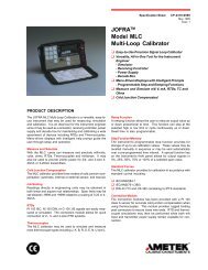
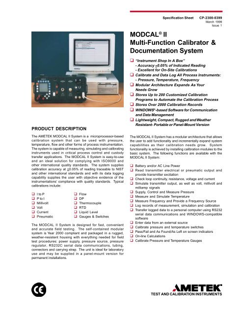
PRODUCT DESCRIPTION<br />
The AMETEK MODCAL <strong>II</strong> <strong>System</strong> is a microprocessor-based<br />
calibration system that can be used with pressure,<br />
temperature, flow and other forms of process instrumentation.<br />
The system is capable of measuring, simulating and calibrating<br />
instruments used in critical process control and custody<br />
transfer applications. The MODCAL <strong>II</strong> <strong>System</strong> is easy-to-use<br />
and an ideal solution for complying with ISO9000 and<br />
other international quality standards. The system supplies<br />
calibration accuracy at +0.05% of reading traceable to NIST<br />
and other international standards and with its data logging<br />
capability supplies the user with objective evidence of the<br />
instrumentations’ compliance with quality standards. Typical<br />
calibrations include:<br />
q I to P q Flow<br />
q P to I q DP<br />
q Millivolt q Thermocouple<br />
q Volt q RTD<br />
q Current q Liquid Level<br />
q Pneumatic q Gauges & Switches<br />
The MODCAL <strong>II</strong> <strong>System</strong> is designed for fast, convenient<br />
and accurate field testing. The self-contained modular<br />
system is Year 2000 compliant and packaged in a rugged,<br />
weather-resistent housing with everything needed for field<br />
test procedures: power supply, pressure source, pressure<br />
regulator, RS232C serial data communications, tubing,<br />
connectors and carrying strap. The unit is ideal for laboratory<br />
use and may be supplied in a panel-mount version for<br />
permanent installations.<br />
Specification Sheet CP-2300-0399<br />
March 1999<br />
Issue 1<br />
MODCAL ® <strong>II</strong><br />
<strong>Multi</strong>-<strong>Function</strong> <strong>Calibrator</strong> &<br />
<strong>Documentation</strong> <strong>System</strong><br />
q “Instrument Shop In A Box”<br />
- Accuracy +0.05% of Indicated Reading<br />
- Excellent for On-Site Calibrations<br />
q Calibrate and Data Log All Process Instruments:<br />
- Pressure, Temperature, Frequency<br />
q Modular Architecture Expands As Your<br />
Needs Grow<br />
q Stores Up to 200 Customized Calibration<br />
Programs to Automate the Calibration Process<br />
q Stores Over 2000 Calibration Records<br />
q WINDOWS ® -based Software for Communication<br />
and Data Management<br />
q Lightweight, Compact, Rugged and Weather<br />
Resistant- Portable or Panel-Mount Version<br />
The MODCAL <strong>II</strong> <strong>System</strong> has a modular architecture that allows<br />
the user to add functionality and incrementally expand system<br />
capabilities as their calibration needs grow. <strong>System</strong><br />
functionality is achieved by installing calibration modules to the<br />
basic system. The following functions are available with the<br />
MODCAL <strong>II</strong> <strong>System</strong>:<br />
q Battery and/or AC Line Power<br />
q Read transmitter electrical or pneumatic output and<br />
provide transmitter excitation<br />
q Check loop continuity, resistance, voltage and current<br />
q Simulate transmitter output, as well as volt, millivolt and<br />
milliamp signals<br />
q Supply, Control and Measure Pressure<br />
q Measure and Simulate Temperature<br />
q Measure Frequency and Provide a Frequency Source<br />
q Log records of measurement, simulation and calibration<br />
q Transfer logged data to a personal computer using RS232<br />
serial data communications and WINDOWS-compatible<br />
software<br />
q Enter data from an external source<br />
q Calibrate pressure and temperature switches<br />
q Pass/Fail and As Found/As Left on screen indicators<br />
q On-line Calculations<br />
q Calibrate Pressure and Temperature Gauges<br />
TEST AND CALIBRATION INSTRUMENTS
SYSTEM ARCHITECTURE<br />
The MODCAL <strong>II</strong> <strong>System</strong> can be comprised of many combinations<br />
of calibration modules. The primary system consists of a<br />
main chassis assembly which houses the Stationary Display<br />
Module. The Stationary Display Module includes the power<br />
supplies, LCD Display, membrane keypad, multimeter, transmitter<br />
simulator, frequency and datalogging functions. The<br />
keypad and LCD display are the main interface with the system.<br />
The keypad offers both tactile and audio feedback. The<br />
LCD display is a 128 x 128 pixel dot matrix LCD and can<br />
display four lines of data simultaneously, e.g. input, output,<br />
ideal output and percent of error.<br />
The MODCAL <strong>II</strong> <strong>System</strong> can be panel mounted or supplied in<br />
an impact-, water- and dust-resistant case which is impervious<br />
to many chemicals. The case contains the Stationary Display<br />
Module and has slots for housing up to four additional modules.<br />
These modules can be combined in any combination of<br />
pressure, temperature, regulator or pump modules. A 9 pin<br />
RS232C connector is also provided for serial communications<br />
to peripherals such as a personal computer or printer.<br />
The <strong>Multi</strong>meter used in the MODCAL <strong>II</strong> <strong>System</strong> is also part of<br />
the Stationary Module. Voltage, ohm, frequency and current<br />
input posts are located on the instruments front panel. The<br />
output posts are also located on the front panel. The multimeter<br />
inputs are electrically isolated from all other functions of<br />
the system.<br />
Pressure Module<br />
The Pressure Module is removable and fits into any of the four<br />
available slots provided in the system. The module comes as<br />
a single unit with autoranging. Pressure ranges are available<br />
from 150” H 2 O to 10,000 PSIG ( 400 mBar to 650 Bar) including<br />
compound and absolute ranges. Available ranges include:<br />
Model Code Range<br />
600 0 - 150 in. H O 2 0 - 400 mbar<br />
610 0 - 240 in. H O 2 0 - 600 mbar<br />
620 0 - 30 PSIG 0 - 2 bar<br />
621 vac - 30 PSIG vac - 2 bar<br />
622 0 - 45 PSIA 0 - 2300 mm Hg<br />
630 0 - 150 PSIG 0 - 10 bar<br />
632 0 - 145 PSIA 0 - 7400 mm Hg<br />
640 0 - 500 PSIG 0 - 35 bar<br />
650 0 - 2500 PSIG 0 - 160 bar<br />
660 0 - 5000 PSIG 0 - 350 bar<br />
670 0 - 10000 PSIG 0 - 700 bar<br />
The module is controlled using the keypad and LCD display<br />
on the Stationary Module. Selection of engineering units, zero<br />
offset and added features are included. The Pressure Module<br />
may be set for the following engineering units:<br />
q PSI (pounds per square inch)<br />
q mbar (millibars)<br />
q in Hg (inches of Mercury @ 0 o C)<br />
q mm Hg (millimeters of Mercury @ 0 o C)<br />
q in WC (inches of water @ 20 o C)<br />
q kg/cm 2 (kilograms per square centimeter)<br />
q bar (bars)<br />
q kPa (KiloPascals)<br />
q mm WC (millimeters of water @ 20 o C)<br />
q ft WC (feet of water @ 20 o C)<br />
q cm WC (centimeters of water @ 20 o C)<br />
q in WC6 (inches of water @ 60 o F)<br />
q mPa (milliPascals)<br />
q in WC4 (inches of water @ 4 o C)<br />
q ft WC4 (Feet of water @ 4 o C)<br />
q % (Percent of full scale)<br />
q 4-20 (4-20mA calculated units)<br />
q 1-5V (1-5Vdc)<br />
q Cust (Custom units)<br />
q Flow (Square root function for DPs)<br />
Temperature Module<br />
The Temperature Module is also removable and it also fits into<br />
any of the available four slots provided in the system. This<br />
module measures and simulates thermocouples and RTD temperature<br />
probes. The Temperature Module is programmed<br />
with the mV/temperature equations for the appropriate thermocouple<br />
types and the ohms/temperature equations for the<br />
appropriate RTD type as established by NIST and DIN standards.<br />
The input signals may be displayed in Celsius, Fahrenheit,<br />
Rankin or Kelvin.<br />
The Temperature Module uses standard banana plug connections<br />
for 2-, 3- and 4-wire RTDs, and either a thermocouple<br />
plug or banana plug connection for thermocouples. The thermocouple<br />
input is either on a thermocouple plug connection<br />
or on two input posts located on the front of the Temperature<br />
Module. RTD input is provided on four posts located on the<br />
Temperature Module’s front panel. Cold junction compensation<br />
for thermocouple measurements is either automatic at<br />
ambient temperature or manually set to another temperature.<br />
All control and output display data are done from the keypad<br />
and display on the Stationary Display Module. The display<br />
format allows an operator to set temperature ranges, to designate<br />
the RTD or thermocouple being used, and to select calculated<br />
values to aid in instrument calibration. Selection of<br />
engineering units of measure, zero offset and other features<br />
are included. Various temperature engineering units may be<br />
selected using the Temperature Module including:<br />
q C (Temperature displayed in degrees Centigrade)<br />
q F (Temperature displayed in degrees Fahrenheit)<br />
q K (Temperature displayed in degrees Kelvin)<br />
q R (Temperature displayed in degrees Rankin)<br />
q W/mV (Ohms or millivolts)<br />
q Cjct (Cold Junction)<br />
q JTC (J Type Thermocouple)<br />
q KTC (K Type Thermocouple)<br />
q TTC (T Type Thermocouple)<br />
q ETC (E Type Thermocouple)<br />
q RTC (R Type Thermocouple)<br />
q STC (S Type Thermocouple)<br />
q R48TC (R Type Thermocouple 1948 NIST Curve)<br />
q S48TC (S Type Thermocouple 1948 NIST Curve)<br />
q BTC (B Type Thermocouple)<br />
q Pt100 (Platinum RTD, 100 Ohms, 0.385 Alpha)<br />
q P200A (Platinum RTD, 200 Ohms, 0.385 Alpha)<br />
q P200B (Platinum RTD, 200 Ohms, 0.392 Alpha)<br />
q Ni100 (Nickel RTD, 100 Ohms)
Pump Module<br />
The Pump Module is available in 100 PSI (7 Bar) or 200 PSI<br />
(14 Bar) ranges. The Pump Module provides two pressure<br />
outputs. One output is used to sense the pressure using a<br />
Pressure Module and the other output is connected to the instrument<br />
under test.<br />
Pressure Regulator Module<br />
The Regulator Module is available in ranges of 2, 10, 30 and<br />
100 PSI (100 mBar, 700mBar, 2 Bar, 7 Bar). The Regulator<br />
provides two pressure outputs. One output is normally connected<br />
to a Pressure Module to sense the pressure. The other<br />
output is connected to the instrument under test.<br />
Excitation/Simulate/Loop Output<br />
In the Excitation mode, the MODCAL <strong>II</strong> <strong>System</strong> may be a programmable<br />
voltage, current or frequency source. In the Simulate<br />
mode, the instrument simulates a current transmitter by<br />
controlling the current in an external circuit. In the Loop mode,<br />
the system generates its own 24Vdc current loop circuit to<br />
power and monitor current loop transmitters. The loop current<br />
is sensed for display in the main system. The output is supplied<br />
on the two posts located on the front panel.<br />
Calculator<br />
The MODCAL <strong>II</strong> <strong>System</strong> includes a calculator function. The<br />
Calculator will take the displayed reading from the Meter, Excitation<br />
or one of the modules and perform a numerical calculation.<br />
The result of this calculation will be displayed including a<br />
Pass/Fail indication based on user-defined error limits.<br />
The Calculator has two options: Percent Error and Custom.<br />
The Percent Error is a calculation based on the instrument<br />
under test output and the reference measurement. The reference<br />
measurement is the calculated output or theoretical output<br />
for the instrument under test.<br />
Custom allows the user to input equations using: Addition,<br />
Subtraction, <strong>Multi</strong>plication, Division, Raise to the Power, Cosine,<br />
Sine, Sign function, Absolute, Square Root and Negation.<br />
The maximum amount of characters that may be entered<br />
into an equation is 99.<br />
Data Logger<br />
The Data Logger is an available option. The Data Logger<br />
records ambient temperature, date and time as well as the<br />
data displayed by the Stationary Display Module’s LCD display.<br />
It allows for the transferring of instrument data using an<br />
ASC<strong>II</strong> format. Data is stored on-board the MODCAL <strong>II</strong> <strong>System</strong><br />
with 256K of allocated memory- sufficient to store up to 2048<br />
records. The data is protected by a 3-year lithium battery and<br />
are unaffected by any power loss from the AC line or from the<br />
system’s rechargeable NiCad batterries.<br />
Data may be logged for AS-FOUND data, AS-LEFT data<br />
or other measurements. The records provide objective<br />
evidence of calibration to meet requirements from customers,<br />
quality management and external quality systems including<br />
ISO, FDA, etc.<br />
Data logging may be done manually by the user, or may be<br />
done unattended by the automatic data logging feature. This<br />
feature allows the unit to record any number of readings for<br />
any time unit, e.g., one record per hour. Available time units<br />
are seconds, minutes, hours, days, weeks and periods. Period<br />
is a variable time unit related to a “Start Logging Time” and<br />
“Stop Logging Time”.<br />
Bi-directional Interface Software<br />
The MODCAL <strong>II</strong> <strong>System</strong> is equipped with a bi-directional interface<br />
software package called MC LINK <strong>II</strong>. This is an enhanced<br />
version of the former MC LINK software which allowed only<br />
the downloading of the data from the MODCAL <strong>II</strong> device. MC<br />
LINK <strong>II</strong> Software is Year 2000 Compliant. The former MC LINK<br />
Software is not Year 2000 Compliant and should be replaced<br />
by the newer version.<br />
MC LINK <strong>II</strong> Software is greatly enhanced over the MC LINK<br />
software. Using the MC LINK <strong>II</strong> WINDOWS ® -based software,<br />
the user can store instrument data and organize data by instrument<br />
tag, technician, location, date, etc. Using this information,<br />
users can automate the calibration schedule within<br />
the MODCAL <strong>II</strong> <strong>System</strong>. The MODCAL <strong>II</strong> <strong>System</strong> can then be<br />
used to generate calibration work orders for the technicians<br />
on a daily basis or a user-defined schedule. Using the tag<br />
identification, the technician can “call up” the instrument to be<br />
calibrated, perform the calibration based on pre-programmed<br />
parameters, and record the instrument’s as-found/as-left data,<br />
time, date of calibration and ambient temperature with a single<br />
push of a button. The MODCAL <strong>II</strong> <strong>System</strong> with MC LINK <strong>II</strong><br />
software eliminates problems such as lost records or transposition<br />
errors. customers with non-data logging units may utilize<br />
MC LINK <strong>II</strong> Software only to prepar calibration record formats<br />
on the personal computer and for downloading these<br />
formats to the MODCAL <strong>II</strong> <strong>System</strong>.<br />
Key features of the MC LINK <strong>II</strong> software include:<br />
q a “Wizard” function allowing users to generate custom calibration<br />
record formats and upload them into the MODCAL<br />
<strong>System</strong><br />
q ability to export data in database (.dbf) or ASC<strong>II</strong> comma<br />
delimited (.csv) formats<br />
q a variety of setup options for communications and date/<br />
time format<br />
q ability to SEND, RECEIVE and DELETE data, tags, formats<br />
and procedures to/from a MODCAL <strong>II</strong> calibration device<br />
q ability to generate standard calibration reports containing<br />
“As Found/As Left” data<br />
The recommended hardware requirements for operating the<br />
MC LINK <strong>II</strong> Interface Software are:<br />
Recommended<br />
- 133 MHz PENTIUM or Greater<br />
- 16MB of RAM<br />
- WINDOWS 95 Operating <strong>System</strong><br />
Minimum Requirements<br />
- 33 MHz 486DX<br />
- 4MB of RAM<br />
- WINDOWS 3.1 Operating <strong>System</strong>
FUNCTIONAL SPECIFICATIONS<br />
General Instrument Specifications<br />
CASE<br />
Size (W x H x D): 14.25 x 11.85 x 7.66-inches<br />
36.2 x 30.1 x 19.5cm<br />
Weight: 16.6 lbs (7.5kg)<br />
Weight of portable case with Stationary Display Module, two<br />
Pressure Modules, a Temperature Module, a Pump Module with<br />
cover, charger and accessories.<br />
Keypad: Field and alpha increment, decrement, 4 cursor<br />
controls, 5 functions, menu, Quit, Help, On/Off and backlight key<br />
Display: 128 x 128 pixel dot matrix LCD<br />
Comm Port: 9 Pin Connector, RS232C with programmable baud<br />
rates from 300 to 19,200<br />
Datalogger: 256K memory capable of storing up to 2000<br />
records<br />
Power Input: AC 115Vac +10% @ 50/60 Hz<br />
220/250Vac (switchable) +10% @50/60Hz<br />
AC input from external charger<br />
DC 14-18Vdc<br />
Battery: 9.2V @ 2.2 ampere hours NiCad rechargeable from<br />
external AC/DC input. 15 hours recharge time @ rated line voltage<br />
with unit turned off; battery charging indicator; 15 calibration<br />
cycles typical per charge<br />
Battery Life: 1000 charge/discharge cycles<br />
Battery Monitor: <strong>System</strong> Status Display indicates % remaining<br />
Operating Temperature: 32 o to 122 o F ( 0 o to 50 o C)<br />
Storage Temperature: -4 o to 140 o F (-20 o to 60 o C)<br />
Warm-Up Time: 15 minutes for rated accuracy<br />
The Stationary Display Module includes the power supplies,<br />
LCD Display, membrane keypad, multimeter, transmitter<br />
simulator, frequency and datalogging functions. The keypad and<br />
LCD display are the main interface with the system. The<br />
keypad offers both tactile and audio feedback. The LCD display<br />
is a 128 x 128 pixel dot matrix LCD and can display four lines<br />
of data simultaneously, e.g. input, output, ideal output and<br />
percent of error.<br />
Pressure Module<br />
Model Range and Units<br />
600 150” H 2 O (400mbar)<br />
610 240” H 2 O (600mbar)<br />
620 30 PSIG (2 bar)<br />
621 30 PSI Compound (400mbar Compound)<br />
622 45 PSIA (2300mm Hg Absolute)<br />
630 150 PSIG (10 bar)<br />
632 145 PSIA (7400mm Hg)<br />
640 500 PSIG (35 bar)<br />
650 2500 PSIG (160 bar)<br />
660 5000 PSIG (350 bar)<br />
670 10000 PSIG (700 bar)<br />
Media Compatibility<br />
Air, Nitrogen, Water, Natural Gas, Hydraulic Oil, Alcohol, Glycol plus<br />
gases or liquids compatible with 316L Stainless Steel<br />
Model 600 Only<br />
Limited to media that will not attack polyester, silicon or silicon-based<br />
adhesives.<br />
Accuracy<br />
20 to 100% Full Scale: +0.05% of Reading plus 1 count @ 18 to 28 o C<br />
0 to 20% Full Scale: +0.02% Full Scale plus1 count @ 18 to 28 o C<br />
Warmup Time approximately 15 minutes<br />
Model 632 Only<br />
20% to 100% Full Scale: +0.075% of Reading plus1 count @ 18 to<br />
28 o C<br />
0 to 20% Full Scale: +0.03% Full Scale plus1 count @ 18 to 28 o C<br />
Compensated Temperature<br />
0 to 45 o C<br />
Accuracy Over Temperature<br />
+0.05% Full Scale. In order to enhance accuracy, full scale is<br />
automatically reranged at 100%, 60% and 20% of maximum full scale<br />
Overpressure<br />
300% stability Full Scale<br />
Pressure Connections<br />
1/4-inch NPT Female<br />
Response Time<br />
0.5 seconds maximum for 63% Full Scale<br />
Zero Adjust<br />
+100% Full Scale of selected range<br />
Engineering Units<br />
PSI<br />
mbar<br />
Bar<br />
kPa<br />
MPa<br />
inches Hg<br />
mm Hg<br />
Inches H 2 O 68 o F (20 o C)<br />
inches H 2 O 60 o F (15 o C)<br />
Feet H 2 O 68 o F (20 o C)<br />
Feet H 2 O 40 o F (4 o C)<br />
mm H 2 O 68 o F (20 o C)<br />
mm H 2 O 40 o F (4 o C)<br />
cm H 2 O 68 o F (20 o C)<br />
cm H 2 O 40 o F (4 o C)<br />
kg/cm 2<br />
Specialty Units<br />
% output displayed as<br />
percent of FS<br />
4-20 output in mA displayed<br />
as function of input<br />
pressure<br />
1-5 output in volts displayed<br />
as function of input<br />
pressure<br />
Flow output in mA displayed<br />
as square root function<br />
of the input pressure
Pump Module<br />
100 PSI (7 Bar) MODULE<br />
Operating Pressure<br />
100 PSIG (7Bar)<br />
Burst Pressure<br />
150 PSIG (10 Bar)<br />
Maximum Leak Rate<br />
0.05 PSIG per minute (3.5mbar per minute)<br />
Pressure Connection<br />
1/8-inch NPT Female<br />
Tubing<br />
1/8-inch I.D.<br />
100 PSIG (7 Bar) maximum<br />
200 PSI (14 Bar) MODULE<br />
Operating Pressure<br />
200 PSIG (14Bar)<br />
Burst Pressure<br />
250 PSIG (17 Bar)<br />
Maximum Leak Rate<br />
0.1 PSIG per minute (7.0mbar per minute)<br />
Pressure Connection<br />
1/8-inch NPT Female<br />
Tubing<br />
1/8-inch I.D.<br />
200 PSIG (14 Bar) maximum<br />
Regulator Module<br />
Supply Pressure Maximum<br />
150 PSIG (10 Bar)<br />
Regulator Optimum Supply<br />
2 PSIG (100mBar) 5 PSIG (350mBar)<br />
10 PSIG (700mBar) 30 PSIG (2 Bar)<br />
30 PSIG (2 Bar) 60 PSIG (4 Bar)<br />
100 PSIG (7 Bar) 150 PSIG (10 Bar)<br />
Regulator Minimum Setting<br />
(at optimum supply)<br />
2 PSIG (100mBar) 0 PSIG (0mBar)<br />
10 PSIG (700mBar) 0 PSIG (0 Bar)<br />
30 PSIG (2 Bar) 0.5 PSIG (35 Bar)<br />
100 PSIG (7 Bar) 2 PSIG (100 Bar)<br />
Sensitivity<br />
0.25” H2O<br />
Supply Pressure Effect<br />
0.2psi/100 PSIG change (10mBar/7 Bar)<br />
Materials of Construction (In Contact with Media)<br />
Aluminum, Stainless Steel, Brass, Cadmium-plated Steel, Buna-N<br />
and Dacron, Polyurethane, Copper and Nylon<br />
Pressure Connections<br />
1/8-inch NPT Female<br />
Modularity, Flexibility<br />
The MODCAL <strong>II</strong> <strong>System</strong> features a modular architecture allowing<br />
users to add functionality and performance as their needs change<br />
and expand. Modules simply “plug into” the MODCAL <strong>II</strong> <strong>System</strong>.
FUNCTIONAL SPECIFICATIONS<br />
Temperature Module<br />
Accuracy<br />
Limits for thermocouples are referenced to 73.4 o F (23 o C) cold<br />
junction<br />
Accuracy Over<br />
Compensated<br />
Type Range Temp Range<br />
J 2190 to 32 o F +1.1 o F<br />
32 to -256 o F +1.5 o F<br />
1200 to 0 o C +0.6 o C<br />
0 to -160 o C +0.8 o C<br />
K 2496 to 32 o F +1.3 o F<br />
32 to -202 o F +1.6 o F<br />
1369 to 0 o C +0.7 o C<br />
0 to -130 o C +0.9 o C<br />
T 750 to 32 o F +1.4 o F<br />
32 to -229 o F +2.0 o F<br />
399 to 0 o C +0.8 o C<br />
0 to -145 o C +1.1 o C<br />
E 1830 to 32 o F +0.9 o F<br />
0 to -211 o F +2.1 o F<br />
999 to 0 o C +0.5 o C<br />
0 to -135 o C +1.2 o C<br />
R/S 3212 to 1292 o F +2.9 o F<br />
1968 1292 to 77 o F +3.4 o F<br />
1767 to 700 o C +1.6 o C<br />
700 to 25 o C +1.9 o C<br />
R 3092 to 1292 o F +2.9 o F<br />
1948 1292 to 77 o F +3.4 o F<br />
1700 to 700 o C +1.6 o C<br />
700 to 25 o C +1.9 o C<br />
S 3200 to 1292 o F +2.9 o F<br />
1948 1292 to 77 o F +3.4 o F<br />
1760 to 700 o C +1.6 o C<br />
700 to 25 o C +1.9 o C<br />
B 3270 to 1832 o F +1.1 o F<br />
1832 to 1112 o F +1.6 o F<br />
1112 to 752 o C +2.5 o C<br />
752 to 482 o C +6.8 o C<br />
1799 to 1000 o C +0.6 o C<br />
1000 to 600 o C +0.9 o C<br />
600 to 400 o C +1.4 o C<br />
400 to 250 o C +3.8 o C<br />
Pt 100 .385 1560 to -326 o F +0.9 o F<br />
(IEC 751) 849 to -199 o C +0.5 o C<br />
Pt 200 .385 509 to -326 o F +0.9 o F<br />
(IEC 751) 265 to -199 o C +0.5 o C<br />
Pt 200 .390 509 to -290 o F +0.9 o F<br />
(IEC 751) 265 to -179 o C +0.5 o C<br />
Ni 100 DIN 354 to -74 o F +0.9 o F<br />
(DIN 43760) 179 to -59 o C +0.5 o C<br />
Compensated Temperature<br />
0 to 45 o C<br />
Output Impedance<br />
2000 ohms<br />
0 to 200mV - 0.01mV resolution<br />
0 to 12Vdc - 0.001V resolution<br />
22 to 26Vdc unregulated @ 55mA<br />
Output Current<br />
0 to 55mAdc into 2k ohm load (0.01V resolution)
ORDERING INFORMATION<br />
MODCAL <strong>II</strong> CALIBRATION SYSTEM<br />
Order Number Description<br />
Base Number - Enclosure Type (Note 1)<br />
100 Portable MODCAL <strong>II</strong> <strong>System</strong> with 115Vac Battery Operation<br />
100D Portable MODCAL <strong>II</strong> <strong>System</strong> with Data Logger, 115Vac Battery Operation<br />
110 Portable MODCAL <strong>II</strong> <strong>System</strong> with 220/250Vac Battery Operation<br />
110D Portable MODCAL <strong>II</strong> <strong>System</strong> with Data Logger, 220/250Vac Battery Operation<br />
150 Panel-Mount MODCAL <strong>II</strong> <strong>System</strong> with 115Vac Operation<br />
150D Panel-Mount MODCAL <strong>II</strong> <strong>System</strong> with Data Logger, 115Vac Operation<br />
160 Panel Mount MODCAL <strong>II</strong> <strong>System</strong> with 220/250Vac Operation<br />
160D Panel-Mount MODCAL <strong>II</strong> <strong>System</strong> with Data Logger, 220/250Vac Operation<br />
<strong>Function</strong> Modules - Temperature Type<br />
200 Temperature Module<br />
<strong>Function</strong> Modules -Pressure Pump Type<br />
300 100 PSIG (7 Bar)<br />
310 200 PSIG (14 Bar)<br />
<strong>Function</strong> Modules -Pressure Regulator Type<br />
400 2 PSIG (0.1 Bar)<br />
410 10 PSIG (0.7 Bar)<br />
420 30 PSIG (2 Bar)<br />
430 100 PSIG (7 Bar)<br />
<strong>Function</strong> Modules -Pressure Measuring Type<br />
600 150” H2O (0.4 Bar)<br />
610 240” H2O (0.6 Bar)<br />
620 30 PSIG (2 Bar)<br />
621 Vacuum to 30 PSIG (2 Bar)<br />
622 45 PSIA (2300mm Hg)<br />
630 150 PSIG (10 Bar)<br />
632 145 PSIA<br />
640 500 PSIG (35 Bar)<br />
650 2500 PSIG (160 Bar)<br />
660 5000 PSIG (350 Bar)<br />
670 10000 PSIG (700 Bar)<br />
MC LINK <strong>II</strong> INTERFACE SOFTWARE<br />
Order Number Description<br />
805 MC LINK <strong>II</strong> Software for WINDOWS with Format Wizard (See Note 1)<br />
810 Appliction Protocol Interface (API) for WINDOWS (See Note 2)<br />
Note 1: MC LINK <strong>II</strong> Software for WINDOWS with Format Wizard is provided standard with all<br />
portable and panel mount MODCAL <strong>II</strong> <strong>System</strong>s. Users can update older version MODCAL<br />
<strong>II</strong> <strong>System</strong> with this new software if not currently equipped. MC LINK Software users MUST<br />
upgrade to MC LINK <strong>II</strong> Software due to Year 2000 issues.<br />
Note 2: Application Profocol Interface for WINDOWS provides users with the ability to develop<br />
software drivers for the MODCAL <strong>II</strong> <strong>System</strong> and their own specific application programs.<br />
Please consult AMETEK prior to ordering.
TEST AND CALIBRATION INSTRUMENTS<br />
Headquarters<br />
8600 Somerset Drive<br />
Largo, Florida 33773<br />
Tel (727) 536-7831<br />
Tel (800) 527-9999<br />
Fax (727) 539-6882<br />
Internet Addresses:<br />
www.ametek.com<br />
www.chatillon.com<br />
AMETEK is a registered trademark of AMETEK, Inc.<br />
WINDOWS is a registered trademark of Microsoft Corporation<br />
AMETEK Denmark A/S<br />
Gydevang 32-34<br />
Post Office Box 30<br />
DK-3450<br />
Allerod Denmark<br />
Tel 45 4816 8000<br />
Fax 45 4816 8080<br />
AMETEK is a leading global manufacturer of electrical and electromechanical products for niche<br />
markets. Listed on the New York Stock Exchange (AME) since 1930, AMETEK’s annual sales are<br />
approaching $1billion. Operations are in North America, Europe and Asia, with about one-third of<br />
sales to markets outside the United States.<br />
AMETEK Precision<br />
Instruments Europe GmbH<br />
Rudolf-Diesel-Strasse 16<br />
D-40670, Meerbusch<br />
Germany<br />
Tel 49 2159 9136 0<br />
Fax 49 2159 9136 39<br />
AMETEK Singapore Pvt. Ltd.<br />
10 Ang Mo Kio Street 65<br />
#05-12 TECHPOINT<br />
Singapore 569059<br />
Tel 65 484 2388<br />
Fax 65 481 6588<br />
E-Mail aspl@ametek.com.sg<br />
Information within this document is subject to change<br />
without notice.<br />
ISO 9001<br />
Manufacturer<br />
Pub Code SS-CP-2300-0399<br />
Issued 03/99 Copyright 1998, by AMETEK, Inc.<br />
Printed in U.S.A.