

73 Amateur Radio Today - Free and Open Source Software
73 Amateur Radio Today - Free and Open Source Software
73 Amateur Radio Today - Free and Open Source Software

You also want an ePaper? Increase the reach of your titles
YUMPU automatically turns print PDFs into web optimized ePapers that Google loves.
The best approach is to get an evaluator<br />
board <strong>and</strong> development software which allows<br />
the user to write the program in whatever<br />
language is convenient. translate it into<br />
machin e code. <strong>and</strong> transfer it into an emulator<br />
system which mimics the intended<br />
device. With this scheme. the developer<br />
can write a bit of code. try it out. <strong>and</strong> confirm<br />
that the routine works as intended by<br />
looking at internal memory <strong>and</strong> registers. It<br />
is possible to write the code blind. manually<br />
transfer it into an EPROM. then into the<br />
devi ce via bootstrap mode. but that makes<br />
de bugging very difficult- much like building<br />
a mechanical machine. we ldi ng<br />
the covers on . then trying to figure<br />
O UI it s beh avi or by whether t he<br />
wheels tum!<br />
Fortunately. vendors such as M otorola<br />
ma ke available freeware as<br />
semblers which take the English-language<br />
source code. convert it into the<br />
machine-readable objec t code. <strong>and</strong><br />
put it into file transfer formats suitable<br />
for down loading. (Motorola uses<br />
the "S 19" format.]<br />
Also. Motorola markets low-cost evaluation<br />
<strong>and</strong> programmer boards-a-these ca n be<br />
used to emulate <strong>and</strong> program single-chip<br />
mi c ros. With the " M68H C05 PGM R"<br />
board. for example. small programs can be<br />
downloaded into the 'C8 device's internal<br />
RAM <strong>and</strong> executed without having to program<br />
the on-chip EPRO:-A. Once the routine<br />
is verified. it may be programmed (by<br />
the same board) into the MCU <strong>and</strong> used as<br />
a building block by other routines. With<br />
careful strategy. qui te a long program can<br />
be developed chunk- by -chunk without<br />
need ing fancy tools. My programmer board<br />
(bundled with some pretty good software)<br />
cost me about $68 .05 (US) three years ago<br />
<strong>and</strong> I believe it is still available.<br />
Ask around at the computer e1 ub or local<br />
college <strong>and</strong> look in the ads in magazines<br />
such as Midnight Engineering <strong>and</strong> Circuit<br />
Cellar for possible development bo ard<br />
c<strong>and</strong>idates. If the price for a good system<br />
is too steep (they can run a couple of hundred<br />
dollars) for one budget. consider finding<br />
a buddy (or buddies) to split the cost<br />
with. Not only do you get access to a<br />
system at less cost. but if you share your<br />
experiences. it makes the learning curve a<br />
lot easier!<br />
Hardware Desc ri ption<br />
The circuitry for the Kendraboard fits on<br />
a small single-layer 2.S- x 4.S- printed circuit<br />
board (same size <strong>and</strong> sha pe as the<br />
Julieboard ). It is a very low-tech board<br />
which is well with in the fabri cation abilities<br />
of the average ham. I made mine using<br />
an "ironed-on" reversed-image photocopy<br />
as an etch resi st! My design objectives<br />
were simple: lowest possible density for<br />
ease of home fabrication. me chanically<br />
compatible with the Julieboard. <strong>and</strong> capable<br />
of futu re expansion with the existing<br />
design.<br />
"If the price for a good system is<br />
too steep (they can run a couple<br />
ofhundred dollars) for one budget,<br />
considerfinding a buddy (or buddies)<br />
to split the cost with."<br />
Board logic is very simple: it consists<br />
of a Motorol a MC68HC70SC 8 sing lechip<br />
microcomputer (MCV) <strong>and</strong> its support<br />
circ uitry. The micro itself provides all<br />
operational functions. exce pt for master<br />
clock generation. (It was easier to fit in a<br />
small clock oscillator module than the discre<br />
te oscillator components <strong>and</strong> I didn 't<br />
want to spend a lot of time making them<br />
fit). The ' C 8 was chosen becaus e an<br />
MC68HCOSEVM evaluation board was on<br />
h<strong>and</strong> <strong>and</strong> the chip features:<br />
-7.7K bytes EPROM (or OTP).<br />
- 176 bytes RAM .<br />
-24 bidirectional TIL 110 lines.<br />
-7 input/s pecial purpose TrL lines.<br />
-Serial (ASCII) communicatio ns interface.<br />
-Serial (binary) peripheral interface.<br />
-Easy-to-use 4Q-pin DIP package.<br />
This device is considerably more powerful<br />
than what this application actually requires.<br />
but I wanted to pro vide for future<br />
growth.<br />
The series resistors are used as a buffer<br />
between the "outside world" <strong>and</strong> the MCV<br />
for ESD <strong>and</strong> as an aid to EMI suppression.<br />
The pull up resistors are needed to define<br />
input levels for idle 110 pins [this is tmpor-<br />
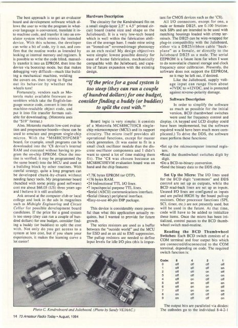
Photo C. Kendraboard <strong>and</strong> Julieboard. (Photo by S<strong>and</strong>y VE3AAC. J<br />
14 <strong>73</strong> <strong>Amateur</strong> <strong>Radio</strong> <strong>Today</strong>- August. 1994<br />
taut for CMOS devices such as the ·C8).<br />
All 110 connectors. exce pt fo r one. a<br />
male or female DB2S. are 0.100 frictionlock<br />
SIPs <strong>and</strong> are intended to be used with<br />
matching housings loaded with c ri mp terminals.<br />
The DB25 can be wire-wrapped for<br />
plug-in compatibility with the Julieboard.<br />
either via a DB 2S/ribbon cable "backpl<br />
ane" a s a female. o r directly to the<br />
Ju lieboard OB2S as a ma le. The serial<br />
EEPROM is a future item for when I want<br />
to do nonvolatile channel storage <strong>and</strong> clock<br />
frequency error calibration. Presently. the<br />
software does not support the EEPROM,<br />
so it may be left out. if desired.<br />
Like the Julieboard. supply vo ltage<br />
input can range from about<br />
+7VDC to + 12VDC. <strong>and</strong> is protected<br />
against reverse-polarit y damage.<br />
Soft ware Description<br />
In orde r to simplify the software<br />
as much as possible for the initial<br />
version, BCD thumbwheel switches<br />
were used for frequency control <strong>and</strong><br />
display. IA keypad <strong>and</strong> LCD display could<br />
have been implemented. but the software<br />
req ui red would have been much more complicated.I<br />
To drive the DDS. the software<br />
must perform these functions:<br />
-Set up the microcomputer internal registers.<br />
-Rcad the thumbwheel swit ches di git by<br />
digit.<br />
-00 a BCD-tO-binary conversion.<br />
-Send the binary data to the DDS chip.<br />
Se t Up the Micro: The 110 lines used<br />
fo r the BCD di git "commons" <strong>and</strong> DDS<br />
co ntro l arc set up as outputs. while the<br />
BCD read-back lines are set up as inputs.<br />
Unused 110 lines are configured as inputs<br />
<strong>and</strong> are pulled HIGH by the board pull-up<br />
resistors. Other processor functions (SPI.<br />
SCI. timer. etc.) are not presently used. but<br />
will be used in the future. At that time,<br />
code will have to be added to initialize<br />
these items. Once the micro has been initialized.<br />
con trol passes to the BCD thumbwheel<br />
switch read -routine.<br />
Reading Ihe BC D T h umbwheei<br />
Swuches: Each BCD switch consists of a<br />
COM terminal <strong>and</strong> four output bits which<br />
are connected/disconnected to the COM<br />
terminal. depending on code. The required<br />
switch function is:<br />
Code: • 4 2 1<br />
0 01' 011 011 011<br />
1 011 011 011 011<br />
2 011 011 011 011<br />
3 011 011 011 011<br />
4 011 011 011 011<br />
5 011 011 011 011<br />
e 011 on 011 011<br />
7 011 011 011 011<br />
• 011 011 011 011<br />
9 011 011 011 011<br />
The output bits are paralleled via diodes:<br />
The cathodes go to the individual 8-4-2-1


