OPERATING INSTRUCTIONS Sylconnect v1.0 - Sylvac
OPERATING INSTRUCTIONS Sylconnect v1.0 - Sylvac
OPERATING INSTRUCTIONS Sylconnect v1.0 - Sylvac

You also want an ePaper? Increase the reach of your titles
YUMPU automatically turns print PDFs into web optimized ePapers that Google loves.
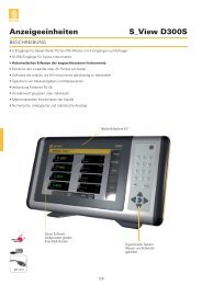
<strong>Sylconnect</strong> <strong>v1.0</strong><br />
Next Generation Metrology Software<br />
Swiss manufacturer of precision measuring instruments since 1969<br />
<strong>OPERATING</strong> <strong>INSTRUCTIONS</strong>
Swiss manufacturer of precision measuring instruments since 1969<br />
Contents<br />
Introduction .................................................................................................................................................. 5<br />
Limitations................................................................................................................................................. 7<br />
Installation ................................................................................................................................................ 8<br />
Getting Started .............................................................................................................................................. 9<br />
Minimum System Requirements .............................................................................................................. 9<br />
Windows Tuning for SylConnect Operation ............................................................................................ 10<br />
USB Resource ...................................................................................................................................... 10<br />
Windows Operation ............................................................................................................................ 10<br />
Security ............................................................................................................................................... 10<br />
Installation .............................................................................................................................................. 12<br />
Planning .............................................................................................................................................. 12<br />
Deployment......................................................................................................................................... 12<br />
Licensing ...................................................................................................................................................... 15<br />
Operation .................................................................................................................................................... 17<br />
Starting SylConnect ................................................................................................................................. 17<br />
Connecting Instruments .......................................................................................................................... 17<br />
Instrument Detection and Configuration ................................................................................................ 19<br />
Instrument Manipulation ........................................................................................................................ 20<br />
Understanding SylConnect ...................................................................................................................... 20<br />
Channel Widgets ......................................................................................................................................... 21<br />
Widget Structure ..................................................................................................................................... 21<br />
Scoreboard .......................................................................................................................................... 23<br />
Channel Setup Dialog .............................................................................................................................. 24<br />
Display Area ............................................................................................................................................ 25<br />
Sequential Measures............................................................................................................................... 27<br />
Multi‐Gauges Measures ...................................................................................................................... 28<br />
Multi‐gauges with One Instrument Using Several Channels .............................................................. 29<br />
Global Commands ................................................................................................................................... 30<br />
Measuring Modes ............................................................................................................................... 31
Swiss manufacturer of precision measuring instruments since 1969<br />
Value Modes ....................................................................................................................................... 32<br />
Tolerance ON/OFF .............................................................................................................................. 32<br />
PRESET ................................................................................................................................................. 32<br />
Channel ID, Sequence Order and Undo .................................................................................................. 32<br />
Channel ID ........................................................................................................................................... 32<br />
Sequence Order .................................................................................................................................. 32<br />
Undo .................................................................................................................................................... 32<br />
Systems with Touch Screen .................................................................................................................... 32<br />
Enabling the OSK ................................................................................................................................. 32<br />
Using OSK ............................................................................................................................................ 34<br />
Exporting Data ............................................................................................................................................ 35<br />
Data Store ............................................................................................................................................... 35<br />
Export to Excel ........................................................................................................................................ 35<br />
Configuration ...................................................................................................................................... 36<br />
Starting Data Export ............................................................................................................................ 36<br />
Assigning values to cells ...................................................................................................................... 36<br />
Configuring a new template ............................................................................................................... 37<br />
Copy an existing Excel report form into the SylConnect blank template ........................................... 38<br />
Variables.............................................................................................................................................. 39<br />
Create template with statistical calculations .......................................................................................... 40<br />
Introduction ........................................................................................................................................ 40<br />
Creating a table ................................................................................................................................... 40<br />
The ‘Ghost’ Table ................................................................................................................................ 40<br />
The Chart ............................................................................................................................................. 41<br />
Notes ................................................................................................................................................... 41<br />
Example ............................................................................................................................................... 42<br />
Operating Commands ................................................................................................................................. 43<br />
Profiles .................................................................................................................................................... 43<br />
Global Variables .................................................................................................................................. 44<br />
Excel Template File ............................................................................................................................. 44
Swiss manufacturer of precision measuring instruments since 1969<br />
Profile .................................................................................................................................................. 45<br />
Default Profile ..................................................................................................................................... 45<br />
Note on File Locations ......................................................................................................................... 45<br />
Keyboard Shortcuts ................................................................................................................................. 46<br />
Channel Number and Keyboard Shortcut Association............................................................................ 46<br />
Foot pedals .............................................................................................................................................. 47<br />
Configuration Language ......................................................................................................................... 48<br />
Pin code ................................................................................................................................................... 48<br />
Visuals ..................................................................................................................................................... 48<br />
Troubleshooting .......................................................................................................................................... 49<br />
Unable to start SylConnect ..................................................................................................................... 49<br />
Instruments not detected by SylConnect ............................................................................................... 50<br />
Export problem to EXCEL ........................................................................................................................ 51<br />
Problem Installing SylConnect 1 ............................................................................................................. 53<br />
Windows 7 Tuning Tips ............................................................................................................................... 54<br />
Introduction ............................................................................................................................................ 54<br />
Analyzing Tools ....................................................................................................................................... 54<br />
DPC Latency Checker .............................................................................................................................. 54<br />
LatencyMon ............................................................................................................................................ 56<br />
Stop Non Required Software Applications ............................................................................................. 60<br />
Disconnect Unnecessary USB or Firewire Devices .................................................................................. 60<br />
BIOS Update ............................................................................................................................................ 60<br />
Chipset and Mainboard Components Driver Update ............................................................................. 61<br />
Energy Options ........................................................................................................................................ 61<br />
Graphic Card Tools .................................................................................................................................. 63<br />
Laptop Energy Saving Tools .................................................................................................................... 64<br />
Disable Power Saving Option of the USB Ports ....................................................................................... 64<br />
Microsoft Hotfix for USB Spikes .............................................................................................................. 65<br />
Aero ......................................................................................................................................................... 65
Introduction<br />
5<br />
Swiss manufacturer of precision measuring instruments since 1969<br />
SylConnect is the next generation Metrology software. It consists of the following key features:<br />
� Touch Screen intuitive user experience: Users benefit from a simple to use user interface designed<br />
mostly for Touch Screen devices. All operation can be done without a mouse and a keyboard;<br />
numerical values such as tolerances can be entered using contextual keypads and text can be<br />
entered via on‐screen keyboard. Alternatively, users can still enter values using a keyboard and<br />
mouse if a touch screen is not available.<br />
� Simplified Data Export to Spreadsheets: this is achieved by embedding a component (an ActiveX<br />
control) into the target spreadsheet. The control takes care of visually guiding the user through the<br />
configurations of the export profile as well as capturing the data during the measuring session.<br />
� Automated instrument management and monitoring. SylConnect provides a number of tools for<br />
monitoring connection activities (e.g. automated instrument connection or disconnection to a USB<br />
port), identifying the resulting COM port, recognizing the instrument if applicable (DUPLEX<br />
instrument) and applying the corresponding profile.<br />
� Flexible measure handling with multiple visual representations, tolerance indicators, analog gauge<br />
and Bar Chart.<br />
� Various measurement modes: application based (DIRECT), instrument based (BLIND) or timer based.<br />
� Multiple measurement captures: actual, min/max, delta etc.<br />
� Sequential measurements with visual and audio sequence indications.<br />
� Measure controls can be alternatively invoked using:<br />
1. Keyboard shortcuts as found commonly in many applications.<br />
2. Associations with physical devices such as foot pedals.<br />
3. The on‐screen commands with the mouse or Touch Screen.<br />
4. Direct interaction from the instrument (SET button).<br />
� Touch Screen based Canvas configuration: simple screen configuration based on a select and touch<br />
to position widgets on the screen.<br />
� Multi‐mode function buttons save screen real‐estate, decrease the complexity of the interface and<br />
improve the operation ergonomic.<br />
� SylConnect does support Inspection concepts by allowing user to associate a measurement profile to<br />
inspection data including:<br />
o Fixture and operation details.<br />
o Part pieces and drawing characteristics.<br />
o Any other user defined variables to be exported to spreadsheet.<br />
� A highly configurable display area with measure displays that can be moved and rearranged at will.<br />
SylConnect Operating Instructions
6<br />
Swiss manufacturer of precision measuring instruments since 1969<br />
� Multi operator operation, the software is designed to identify independent measure control device<br />
(foot pedals) and notifications to support deployment of a single SylConnect system managing a<br />
number of connected operators each performing independent measures.<br />
� Multiple language support and customization.<br />
SylConnect Operating Instructions
Limitations<br />
The current version of SylConnect has the following restrictions:<br />
7<br />
Swiss manufacturer of precision measuring instruments since 1969<br />
1. Support of <strong>Sylvac</strong> FTDI based instruments only. (SIMPLEX or DUPLEX)<br />
2. A limited support of retro‐commands.<br />
3. A limit of 16 channels in any combination of sequence or physical instruments.<br />
SylConnect Operating Instructions
8<br />
Swiss manufacturer of precision measuring instruments since 1969<br />
Installation<br />
SylConnect is installed on a single machine as a standalone application. Internet connection is not<br />
required to run SylConnect. Connecting a device to the computer is done using USB. Several instruments<br />
can be connected on a single USB hub as long as the hub can deliver enough power for all connected<br />
instruments. We recommend using externally powered USB hubs to ensure sufficient power supply.<br />
SylConnect Operating Instructions
Getting Started<br />
Minimum System Requirements<br />
SylConnect is supported on the following Operating Systems:<br />
� Windows XP SP3.<br />
� Windows 7 32‐bit and 64‐bit.<br />
Minimum hardware requirements:<br />
� PC (Intel® or AMD®) with or without Touch Screen.<br />
� CPU 1.5 GHz or better.<br />
� Touch Screen or Mouse and Keyboard.<br />
� 1 GB of RAM.<br />
� 100 MB available HDD space.<br />
� 1 USB port minimum.<br />
Microsoft Excel versions:<br />
� Microsoft Excel 2007<br />
� Microsoft Excel 2010<br />
Mail client program<br />
� MS‐Outlook<br />
� Thunderbird<br />
9<br />
Swiss manufacturer of precision measuring instruments since 1969<br />
� SylConnect uses privileged system resources, hence the security level of the user<br />
installing and running the application should be Administrator equivalent.<br />
� When using Excel 2010, make sure you are using the complete version (not the trial<br />
version). The complete version allows Macros to run which is required when<br />
SylConnect communicates in real time with Excel.<br />
� An email client program is required for the generation of license requests. This is<br />
required even if the PC is not connected to the Internet.<br />
� We recommend the PC used to run SylConnect is dedicated to this application.<br />
Unexpected behavior may be resulting to parallel operations such as Anti Viruses,<br />
internet related processing and any other application running in the background.<br />
SylConnect Operating Instructions
10<br />
Swiss manufacturer of precision measuring instruments since 1969<br />
Windows Tuning for SylConnect Operation<br />
Regardless whether the PC is connected to the Internet or not the following considerations should be<br />
undertaken whenever deploying SylConnect for production:<br />
� USB resource.<br />
� Windows System Operation.<br />
� Security.<br />
USB Resource<br />
SylConnect relies on USB ports for its operation. Therefore, it is best if the system hosting SylConnect<br />
has fully functional USB ports. The USB functions depend on the following:<br />
� Properly configured and functioning hardware.<br />
� Functioning USB controller (master driver).<br />
� Adequate cabling.<br />
� Up to date firmware and BIOS.<br />
� Properly configured Root Hub (IRQ).<br />
There are numerous documentations on troubleshooting USB operation on Windows including:<br />
http://support.microsoft.com/kb/310575 for Windows XP SP3<br />
Windows Operation<br />
We recommend installing SylConnect on a system having running background services limited to the<br />
essential services only. Some services can interfere with SylConnect operations, taking precedence over<br />
it which results in SylConnect looking “frozen” or with abnormal or slow behavior. This may include:<br />
� Automated updating service<br />
� Communication with Third Party Devices or Applications<br />
� Gadgets or “Advisors”<br />
� Other services/programs run automatically at system startup and/or login<br />
Several free utilities can be used to perform system services tuning including Autoruns for Windows<br />
(http://technet.microsoft.com/en‐us/sysinternals/bb963902) which can be used to identify and disable<br />
unnecessary services.<br />
Security<br />
We recommend running SylConnect on a platform with disabled security measures e.g.<br />
� No Firewalls<br />
� No Antivirus or Spyware detectors<br />
� No Automatic Updates<br />
SylConnect Operating Instructions
Depending on the OS version, tips and guides can be found at:<br />
11<br />
Swiss manufacturer of precision measuring instruments since 1969<br />
� http://www.mydigitallife.info/disable‐or‐turn‐off‐windows‐xp‐security‐center‐permanently/ for<br />
Windows XP<br />
� http://www.mydigitallife.info/how‐to‐disable‐and‐turn‐off‐uac‐in‐windows‐7/ for Windows 7<br />
User Account Control<br />
� http://technet.microsoft.com/en‐us/magazine/dd492018.aspx to remove monitoring and<br />
turning off security messages in Windows 7<br />
Please also refer to the relevant documentation if an Antivirus is installed (AVG, Symantec etc.)<br />
� AVG is known to raise “false positive” when installing SylConnect. We recommend<br />
disabling or removing AVG Antivirus from the system hosting SylConnect (see<br />
http://www.mytechguide.org/7871/how‐to‐completely‐remove‐avg‐antivirus/ for<br />
details on removing AVG).<br />
SylConnect Operating Instructions
12<br />
Swiss manufacturer of precision measuring instruments since 1969<br />
Installation<br />
SylConnect installation is provided with an installation program (InstallShield). The following describes<br />
the installation process.<br />
Planning<br />
Depending on the scenario, SylConnect uses a number of peripherals to interconnect instruments and<br />
manual triggers (foot pedals).<br />
The installation may require the following:<br />
1. A PC with or without Touch Screen compliant to the above requirements<br />
2. A number of <strong>Sylvac</strong> instruments (SIMPLEX or DUPLEX)<br />
3. One or more USB Hubs<br />
4. Foot pedal if applicable<br />
Deployment<br />
Once the application program is downloaded from the repository, the installation is started by right‐<br />
clicking on the file and clicking on “run as administrator”:<br />
SylConnect Operating Instructions
13<br />
Swiss manufacturer of precision measuring instruments since 1969<br />
� If you are logged as Administrator, you may not need to use the Run as<br />
administrator option since your privileges are sufficient.<br />
The system request a confirmation for running the application, click ‘YES’, and continue to the main<br />
installation dialog:<br />
Click on ‘Next’.<br />
Select an installation directory, by default, the software is installed in the usual Program Installation<br />
directory, under Windows 7 this is in C:\Program Files (x86)\SylConnect<br />
The installer further asks the user for a program’s shortcut in the Start Menu, by default, this will be<br />
located in the ‘SylConnect’ folder.<br />
Finally, the installer requests whether a desktop icon is wanted.<br />
The installer then summarizes the user choices, for example:<br />
Destination location:<br />
C:\Program Files (x86)\SylConnect<br />
Start Menu folder:<br />
SylConnect<br />
SylConnect Operating Instructions
Additional tasks:<br />
14<br />
Additional icons:<br />
Create a desktop icon<br />
Swiss manufacturer of precision measuring instruments since 1969<br />
� We recommend keeping this default as it will be easier at a later stage to locate<br />
resources such as language files, excel spreadsheets and also to perform un‐installs.<br />
� It is not necessary to remove a previous installation; the installer takes care of<br />
updating a previous installation accordingly.<br />
At this stage, the installation process can start, click on ‘Install’.<br />
Once the installation is done, the installer prompts for the installation of the FTDI drivers. Normally, the<br />
FTDI drivers installation should be done to ensure that the latest drivers are always installed.<br />
Click on ‘Finish’.<br />
If the Install FTDI driver option is selected, a number of DOS box will be displayed, until the installation is<br />
complete.<br />
SylConnect Operating Instructions
15<br />
Swiss manufacturer of precision measuring instruments since 1969<br />
Licensing<br />
When starting SylConnect for the first time, the user is prompted to enter the information required to<br />
get a license.<br />
If the user chooses ‘Register Later’, a temporary license of 30 days is activated.<br />
� The fields marked with an asterisk (‘*’) are compulsory.<br />
When the user enters the required information a registration key is created and an email is<br />
automatically generated to request a license key:<br />
SylConnect Operating Instructions
When clicking on ‘Register’, an email is created:<br />
16<br />
Swiss manufacturer of precision measuring instruments since 1969<br />
� If your PC is not connected to the Internet, please copy the content of the email<br />
and create an email from an Internet connected machine. Send the email to<br />
SylConnect@sylvac.ch with ‘Request License Key’ in the ‘Subject’ field.<br />
SylConnect Operating Instructions
Operation<br />
17<br />
Swiss manufacturer of precision measuring instruments since 1969<br />
Starting SylConnect<br />
Once SylConnect is properly installed and the license preliminary are complete, the following screen is<br />
displayed when the user launch the application.<br />
Connecting Instruments<br />
Connecting instruments is done simply by connecting the USB cable to the PC either directly or on a<br />
connected USB hub.<br />
SylConnect supports instruments connected to the PC USB port by one of the following cable:<br />
� PROXIMITY<br />
� POWER<br />
� OPTO<br />
� When using a POWER cable, please ensure that the instrument is properly powered<br />
by the cable. If the instrument does not seem to be powered, SylConnect will not<br />
detect it. Please refer to the corresponding documentation for more details on<br />
POWER cable operation.<br />
� When using an OPTO cable, make sure the orientation of the connector matches<br />
the receiver of the instrument. If the connector is wrongly orientated, no measure<br />
will be performed although the instrument is detected.<br />
SylConnect Operating Instructions
18<br />
Swiss manufacturer of precision measuring instruments since 1969<br />
When connecting instruments for the first time on a new installation, the detection can take a moment<br />
(up to a minute depending on the PC performance), this is due to the fact that the PC installs locally an<br />
operation FTDI driver for the USB port being used. On Windows 7, an icon in the bottom‐right corner<br />
indicates the progress and completion of the installation:<br />
FTDI USB driver installation<br />
indication.<br />
(This indicates that the<br />
installation is complete and<br />
working)<br />
SylConnect Operating Instructions
Instrument Detection and Configuration<br />
When an instrument is detected the following popup is displayed:<br />
Indication of COM<br />
port, cable serial<br />
number and<br />
instrument model.<br />
Channel number.<br />
Text to display to<br />
identify the<br />
channel<br />
19<br />
Swiss manufacturer of precision measuring instruments since 1969<br />
Once the instrument configurations are completed, the current value of the instrument is displayed.<br />
Whenever the instrument is disconnected its associated widgets are deleted.<br />
Specify the number of<br />
channels in sequence.<br />
Permits access to the<br />
channel configuration<br />
dialog.<br />
The area to display the<br />
channel widget.<br />
SylConnect Operating Instructions
20<br />
Swiss manufacturer of precision measuring instruments since 1969<br />
Instrument Manipulation<br />
We recommend setting up the instrument fully prior connecting it to SylConnect. Depending on the<br />
instrument, the MODE command may produce loss of connectivity with SylConnect. This results in<br />
SylConnect interpreting this loss as an instrument disconnection implying the deletion of its associated<br />
widgets. In this scenario, the user must reconnect the instrument (unplug and re‐plug the USB cable)<br />
then reload the profile (if a profile has been defined).<br />
The data connectivity indicator on most instruments is indicated as follows:<br />
The absence of the data indicator icon on the instrument display means that the communication with<br />
SylConnect is lost.<br />
Understanding SylConnect<br />
The SylConnect display is split in three parts:<br />
Data Indicator<br />
icon<br />
1. The main area where the channel measurement “widgets” are displayed.<br />
2. Global measure command buttons, these commands globally impact the way measures are<br />
captured and processed and are located below.<br />
3. Software behavior commands located on the right side.<br />
SylConnect Operating Instructions
21<br />
Swiss manufacturer of precision measuring instruments since 1969<br />
A typical display of SylConnect in operation (here is one instrument connected with 8 channels<br />
configured in sequence)<br />
Channel Widgets<br />
A channel widget is the main display area representing a measure. The widget can display various values<br />
depending on the configuration:<br />
� ACTUAL: This is the current measure as actually captured from the instrument.<br />
� MIN: The minimum value measured for this channel.<br />
� MAX: The maximum value measured for this channel.<br />
� DELTA: The differential between the min and max value.<br />
Widget Structure<br />
The Channel Widget consists of three parts:<br />
Channel Measure Display<br />
Global measure commands<br />
Channel<br />
Widget<br />
Software<br />
behavior<br />
commands<br />
1. The channel number indicator. This pad can be clicked or touched to access the channel score<br />
board. The channel number also visually indicates which channel is active when performing<br />
sequential measures.<br />
2. The channel local command button allowing clearing locally the measured and calculated values<br />
as well as setting the PRESET locally.<br />
SylConnect Operating Instructions
22<br />
Swiss manufacturer of precision measuring instruments since 1969<br />
3. The measured value area. This area can be touched or clicked to access the channel settings<br />
popup. It can display the values as a digital value or in bar chart and analog gauge form.<br />
The digital display of measures resembles the picture below.<br />
The color of the measured value follows the conventions depending on the selected tolerance mode.<br />
The colors can be summarized as in the table below:<br />
≤ LTL 1 ��� � � � ��� ≥UTL 2<br />
TOLERANCE<br />
� Internal Measure YELLOW OK RED<br />
� External Measure RED OK YELLOW<br />
≤ LTL ≤LCL 3 ��� � � � ��� ≥UCL 4 ≥UTL<br />
SPC 5 RED YELLOW OK YELLOW RED<br />
In TOLERANCE mode, the yellow color indicates REWORK, whereas RED indicates DISCARD.<br />
1 LTL = Lower Tolerance Limit<br />
2 UTL = Upper Tolerance Limit<br />
3 LCL = Lower Control Limit<br />
4 UCL = Upper Control Limit<br />
5 Statistical Process Control<br />
Number of<br />
measures<br />
performed<br />
Lower<br />
Tolerance<br />
Value<br />
Channel title<br />
Nominal<br />
Value<br />
Current unit<br />
Measured value<br />
Bar chart<br />
Upper<br />
Tolerance<br />
Value<br />
SylConnect Operating Instructions
23<br />
Swiss manufacturer of precision measuring instruments since 1969<br />
The bar chart below the value depicts the color and range of the measure according to the settings. The<br />
bar chart also specifies the tolerance boundaries and the nominal value corresponding to the artifact<br />
characteristics.<br />
The tolerance settings are done using the Tolerance dialog (see below in this document).<br />
The analog display is as follows:<br />
As above, the center of a gauge is following the color convention to indicate the REWORK or DISCARD<br />
nature of the artifact being measured. Tolerances must be activated to use the analog display.<br />
Scoreboard<br />
The channel scoreboard is accessed by clicking on the channel number pad. It summarizes the setup and<br />
calculated values for a channel. The scoreboard values can be cleared locally or globally by clicking on<br />
the respective action button.<br />
SylConnect Operating Instructions
Channel Setup Dialog<br />
The dialog allows setting up the channel parameters including:<br />
1. Resolution.<br />
2. Units.<br />
3. Measuring mode.<br />
4. Channel Title to be displayed.<br />
5. Tolerance mode.<br />
6. Measure characteristics.<br />
7. Tolerance values.<br />
8. Nominal values.<br />
The setup dialog is accessed by clicking on the widget’s central area:<br />
24<br />
Swiss manufacturer of precision measuring instruments since 1969<br />
Each channel has a specific configuration according to the artifact characteristics and measuring<br />
protocol.<br />
The Setup dialog allows setting up a particular preset value for the instrument.<br />
SylConnect Operating Instructions
25<br />
Swiss manufacturer of precision measuring instruments since 1969<br />
Display Area<br />
The display area offers great flexibility, it allows users to move and resize widgets, specify backgrounds<br />
to display a mechanical draft etc. For example, a display area can be configured as such:<br />
The Widgets can be moved and resized simply by clicking on the upper part of the window, keeping the<br />
mouse clicked and dragging the window wherever required. The upper part can also be double clicked<br />
for the same behavior and then the window moved. The window can be resized by moving the pointer<br />
to an edge of the window and using standard Windows resizing command (click, drag and release).<br />
SylConnect Operating Instructions
26<br />
Swiss manufacturer of precision measuring instruments since 1969<br />
The background can be specified by right‐clicking on the background and choosing a file to display:<br />
The following formats are supported:<br />
� PNG: Portable Network Graphic.<br />
� JPG: Jpeg.<br />
� BMP: Windows Bitmap.<br />
� GIF: Graphical Interchange Format.<br />
� TIFF: Tagged Image File Format.<br />
� SVG: Scalable Vector Graphic.<br />
NB: .dxf (Autocad) files must be converted in .svg to be used as background<br />
The configuration of the display area can be saved in a profile (see section on Profile for more details).<br />
By the same menu, it is also possible to add and remove one or several channels. For example, if you<br />
have one instrument connected using 2 channels and you want to add one more channel, right click on<br />
the background and select add channel.<br />
SylConnect Operating Instructions
27<br />
Swiss manufacturer of precision measuring instruments since 1969<br />
Sequential Measures<br />
The Sequential measurement allows performing multiple measures on an artifact using a single<br />
instrument or a combination of instruments. This approach allows an operator to manipulate the<br />
measuring device and/or the artifact to actually perform the measure (example : one caliper used to<br />
measure 3 different dimensions on a sleeve).<br />
A measuring sequence can be schematically depicted as follows:<br />
The operator measure the diameter #1, send the data, then the diameter #2, send the data, then the<br />
thickness #3, send the data. At the end, the three values are displayed, the operator can determine if<br />
the part is good or rejected. On a configuration standpoint, the user creates 3 channels for a single<br />
instrument.<br />
To achieve this configuration, assuming the user is using a single caliper, upon instrument detection 3<br />
channels are specified for the instrument.<br />
The corresponding capture measuring cycle is<br />
Channel 1 � Channel 2 � Channel 3 � Channel 1 etc.<br />
The corresponding channel (e.g. active channel) is highlighted in GREEN (above, channel 1 is active).<br />
The display below is an example:<br />
SylConnect Operating Instructions
28<br />
Swiss manufacturer of precision measuring instruments since 1969<br />
Multi‐Gauges Measures<br />
In multi‐gauges mode, all values of all instruments connected will be processed simultaneously. For<br />
example, assume 5 dial gauges connected, each using one display channel. The values of all instruments<br />
connected are taken and sent simultaneously, 1‐2‐3‐4‐5 in once.<br />
SylConnect Operating Instructions
Multi‐gauges with One Instrument Using Several Channels<br />
29<br />
Swiss manufacturer of precision measuring instruments since 1969<br />
In multi‐gauge configuration, the sequence will activate the channels configured for each instrument<br />
separately. For example, assume two connected instruments, one caliper with 4 channels and one<br />
micrometer with one channel. In multi‐gauges mode, the sequence will activate:<br />
1‐5, 2‐5, 3‐5, 4‐5 and back to 1‐5<br />
1‐5 meaning the measure is taken simultaneously on channel 1 and 5.<br />
SylConnect Operating Instructions
30<br />
Swiss manufacturer of precision measuring instruments since 1969<br />
Global Commands<br />
The buttons located on the bottom part of the screen are used to perform global commands on<br />
measurement.<br />
Each button is designed as a multiple choice command control. The arrows on each side allow to select a<br />
functions. The central button allows performing the function (such as capturing a measure, selecting a<br />
value or accessing a specific feature such as Export).<br />
Global commands are presented on the bottom side of the screen as below:<br />
Channel<br />
PRESET<br />
and CLEAR<br />
Value mode<br />
Activation of<br />
MIN/MAX/DELTA<br />
Tolerance ON/OFF<br />
Measuring<br />
modes:<br />
DIRECT<br />
BLIND<br />
TIMER<br />
Click to next<br />
function<br />
Click/Touch to<br />
perform the<br />
function<br />
Click to previous<br />
function<br />
Change:<br />
Channel<br />
number (ID)<br />
Order of<br />
Sequence<br />
Undo<br />
Access to<br />
Export, Store<br />
and Setup<br />
Timer<br />
NB: If the instruments connected are equipped with a DUPLEX electronic and are listed in the table of<br />
supported instruments, the Preset function will be sent to the gauge(s) by remote command. The Preset<br />
value defined will be displayed at the same time on the channel widget and on the instrument display.<br />
SylConnect Operating Instructions
Measuring Modes<br />
SylConnect allows three modes for capturing values.<br />
31<br />
Swiss manufacturer of precision measuring instruments since 1969<br />
� DIRECT: Represented by a loophole. The measure is displayed in real time as captured on the<br />
instrument. The value is captured by:<br />
o Clicking/touching this function button.<br />
o Using a foot pedal (see below for details).<br />
o Using a keyboard shortcut (see below).<br />
� BLIND: Represented by a question mark. The measured value is capture only when triggered by<br />
the user by (there is no real time display of value in this mode):<br />
o Clicking/touching this function button.<br />
o Using a foot pedal (see below for details).<br />
o Pressing on the instrument SET button (see picture).<br />
o Using a keyboard shortcut (see below).<br />
SET button<br />
� TIMER: Represented by an hourglass. The values are captured when the timer delay expires. The<br />
delay is setup using the button on the far right (SETUP TIMER).<br />
When in DIRECT mode, SylConnect queries connected instruments for values approximately<br />
6‐10 times every second. It may happen that the instrument replies ‘ERR2’ (unknown<br />
command) which causes the queries to stop. This results in the values for that instrument<br />
to stop refreshing. To reactivate the value refresh, simply press on the central button’s<br />
navigation arrows (left and right) and go back to DIRECT mode. This can also be achieved by<br />
clicking twice on the button.<br />
SylConnect Operating Instructions
32<br />
Swiss manufacturer of precision measuring instruments since 1969<br />
Value Modes<br />
This function allows selecting the display mode of a channel widget. When a channel is setup, in either<br />
MIN, MAX or DELTA, selecting MIN MAX mode will force the widget to display the respective calculated<br />
value.<br />
Tolerance ON/OFF<br />
By selecting Tolerance ON or OFF, it will display or remove the Bar Chart of all widgets representing<br />
tolerances, only if tolerances have been set.<br />
PRESET<br />
By clicking on this function, the PRESET value configured for the instrument is sent to the instrument.<br />
Channel ID, Sequence Order and Undo<br />
Channel ID<br />
The Channel ID of any widget can be changed at any time using the button represented by a hash sign<br />
(#), clicking on it will pop up a dialog where the user can select the widget he wants to modify and then<br />
type in its new Channel ID from 1‐16.<br />
Sequence Order<br />
Another modifying tool where the user can change the order of sequence when performing sequential<br />
measures, this tool is represented by a capital (S). Clicking it will open a dialog where the user selects a<br />
widget, then uses the tool on the right to move its order up or down in the sequence.<br />
Undo<br />
With this button, it is possible to undo data sent, this tool is represented by a curved arrow pointing left.<br />
This tool is mainly there to undo measures taken that were accidental or imprecise. However, it comes<br />
with limitations such as:<br />
� If the user switches from Multi Gauges to Sequence or from Sequence to Multi Gauges, the user<br />
will not be able to undo.<br />
� If the profile has been changed (for example display channels added), the user will not be able<br />
to undo.<br />
Systems with Touch Screen<br />
System without keyboard and mouse such (Touch Screen devices) provide Touch Screen based<br />
operations and require using the On Screen Keyboard (OSK). Preferably, the OSK should be configured to<br />
allow user to perform various system operation such as logging in and to operate SylConnect.<br />
Enabling the OSK<br />
Windows provides enabling OSK with the Ease of Access Center. To access this utility click on:<br />
SylConnect Operating Instructions
Start>Control Panel>Ease of Access>Ease of Access Center<br />
Click on ‘Use the computer without a mouse or keyboard’.<br />
33<br />
Swiss manufacturer of precision measuring instruments since 1969<br />
SylConnect Operating Instructions
Make sure ‘Use On‐Screen Keyboard’ is selected.<br />
34<br />
Swiss manufacturer of precision measuring instruments since 1969<br />
Using OSK<br />
We recommend launching and pinning the OSK by clicking the Start Orb , clicking All Programs,<br />
clicking Accessories, clicking Ease of Access, and then right‐clicking the On‐Screen Keyboard. Select<br />
option ‘Pin to Taskbar’. An OSK icon will then appear on the task bar:<br />
Click here to show the visual<br />
or On‐Screen Keyboard<br />
The OSK will be then displayable at will:<br />
SylConnect Operating Instructions
Exporting Data<br />
SylConnect supports two ways for exporting data:<br />
6<br />
CSV = Comma Separated Value, data is simply separated by a comma (‘,’). The CSV format is commonly used by<br />
various office applications to exchange and extract data fields. The CSV format can also be used as a Data Source<br />
Name (DSN) to allow on the fly database feeding.<br />
SylConnect Operating Instructions<br />
35<br />
Swiss manufacturer of precision measuring instruments since 1969<br />
1. Store: This is a journal of the measures performed. It provides filtering of data and saving it into<br />
a CSV file for further processing in third party applications such as Database etc.<br />
2. Export: This features a comprehensive export mechanism to Excel spreadsheets using visual<br />
configurations of spreadsheet. Spreadsheet update is real time.<br />
Data Store<br />
The data store is a simple journal of measures. It allows:<br />
� Exporting data to Excel or in a CSV 6 file for further processing.<br />
� Filtering data to export.<br />
� Deleting data selectively (for example to fix a manipulation error).<br />
Export to Excel<br />
Data is exported whenever one of the data capture trigger is used, as described above, the trigger is one<br />
of those below:<br />
� Clicking/touching the data capture function button.<br />
� Pressing on a foot pedal.<br />
� Pressing on the instrument’s SET button.<br />
� Using a keyboard shortcut.<br />
� The timer.<br />
The Export mechanism is invoked by clicking/touching the EXPORT function button or from the STORE<br />
dialog.<br />
The data that can be exported include:<br />
� User defined variables such as department number, drawing or part piece number.<br />
� Values associated to the channel:<br />
o Measured Value.<br />
o Date of measure.<br />
o Title.<br />
o Channel configurations (resolution, unit, tolerances, nominal, etc.).<br />
o Calculated values (min, max, delta etc.).
36<br />
Swiss manufacturer of precision measuring instruments since 1969<br />
Configuration<br />
The Export configuration is accessed by clicking on the Profile button. It allows specifying:<br />
1. Global variables (or Inspection variables) such as Operator name, Drawing number etc. User can<br />
add/remove any global variables.<br />
2. The Excel Template file to use for exporting data. The default is a blank spreadsheet ready for<br />
customization.<br />
Starting Data Export<br />
When the user clicks on the EXPORT Button, the default Excel application is launched and displays the<br />
selected spreadsheet.<br />
Assuming no previous configurations have been made, the spreadsheet is ready for setting up the<br />
export data and variables.<br />
Assigning values to cells<br />
The approach for assigning data to cells is visual. It is based on a simple range selection followed by an<br />
assignment by clicking on the <strong>Sylvac</strong> Control then specifying the data that will fill in the selected range.<br />
A range is a contiguous number of cells which are either horizontal or vertical.<br />
� Multiple sheets are not supported. You can assign cells only where the <strong>Sylvac</strong><br />
Control is located (usually on Sheet 1).<br />
SylConnect Operating Instructions
37<br />
Swiss manufacturer of precision measuring instruments since 1969<br />
To assign values to a cell range, the user selects a range in the spreadsheet, clicks on the <strong>Sylvac</strong> Control<br />
then selects the data to assign:<br />
②Click on<br />
<strong>Sylvac</strong> Control<br />
① Select<br />
Cell Range<br />
When the values are captured they are automatically inserted in the Excel Sheet.<br />
Please note the following when inserting data:<br />
③ Perform<br />
Assignment<br />
� DIRECT Mode, SylConnect must have the focus (that is, it must the foreground application).<br />
� BLIND Mode, SylConnect can run in the background or be minimized.<br />
Configuring a new template<br />
Configuring a new template is done by editing the blank template and saving it as an<br />
“Excel Macro‐Enabled Workbook”.<br />
Then, perform the cells assignments as described previously, and save these settings in a Profile (the<br />
profile keeps the specific setup generally reflecting a protocol). The profile saves the current<br />
configuration of channels, display setup and export settings.<br />
SylConnect Operating Instructions
38<br />
Swiss manufacturer of precision measuring instruments since 1969<br />
Copy an existing Excel report form into the SylConnect blank template<br />
Creating a new template from an existing Excel Spreadsheet, can be simply done by copying the relevant<br />
cells from the original spreadsheet into the ‘blank’ template which is provided in the template<br />
subdirectory. To achieve this, follow these steps:<br />
1. Copy the cells in the existing Excel file report<br />
2. Open the blank template file in My Document\<strong>Sylconnect</strong>\templates\blank.xlsm<br />
3. Paste the cells in the blank template file at the desired location<br />
4. Save as “Excel Macro‐Enable Workbook” with a new file name.<br />
5. If this new template is dedicated to a specific profile and that the instruments are already<br />
connected, you can make the assignment of cells and save the sheet.<br />
This procedure can be illustrated as follows:<br />
1. Select cells<br />
to copy from<br />
original sheet<br />
2. Copy the<br />
selected cells<br />
into the blank<br />
sheet<br />
(blank.xslm)<br />
3. Save the new<br />
sheet as an Excel<br />
Macro Enabled<br />
Workbook with a<br />
new name<br />
SylConnect Operating Instructions
39<br />
Swiss manufacturer of precision measuring instruments since 1969<br />
Variables<br />
There are a number of channel variables that can be assigned to cells, the following table summarizes<br />
the variables available at the time of this writing. The column dimension indicates a single value or<br />
multiple values assignment.<br />
Abbreviation Description Dimension<br />
VALUE The actual measured value N<br />
DATETIME The date and time of the measure N<br />
# Is the measure number N<br />
LABEL The Title displayed in the Widget 1<br />
ID Channel Identification 1<br />
RES The resolution in number of decimals 1<br />
UNIT The text representing the unit 1<br />
USL The upper tolerance limit 1<br />
LSL The lower tolerance limit 1<br />
NOMINAL The nominal dimension of the artifact 1<br />
UCL The Upper Control Limit (in SPC mode) 1<br />
LCL The Lower Control Limit (in SPC mode) 1<br />
MIN The calculated minimum measure of the channel 1<br />
MAX The calculated maximum measure of the channel 1<br />
DELTA The differential between the min and max calculated for the channel 1<br />
MEAN The average measurement for the channel 1<br />
TOL The tolerance mode (internal or external) 1<br />
SylConnect Operating Instructions
40<br />
Swiss manufacturer of precision measuring instruments since 1969<br />
Create template with statistical calculations<br />
Introduction<br />
This section is to help better understand how a SPC chart works, the formulas behind it, and how to<br />
format it. Three main things will be looked at in this section:<br />
1. creating a table,<br />
2. creating a ‘ghost’ table,<br />
3. and creating a chart.<br />
An example is given at the end of this chapter<br />
Creating a table<br />
The first table is the table where all the data is inserted by the user, this is the Target Value, USL, LSL and<br />
all of the sample values. Aside from that it is also the one where all the formulas are, Mean, Max, Min,<br />
STDEV, CP and CPK.<br />
You can reveal all of the formulas in the example excel document by clicking on the Formulas tab and<br />
then on Show Formulas. The formulas used in the table are:<br />
MEAN =AVERAGE(X:Y)<br />
MIN =MIN(X:Y)<br />
MAX =MAX(X:Y)<br />
STDEV =STDEV(X:Y)<br />
CP =(USL‐LSL)/(6*STDEV)<br />
CPK =MIN((USL‐MEAN)/(3*STDEV),(MEAN‐LSL)/(3*STDEV))<br />
In this table, (X:Y) is the range of all the sample values which will be used, X should be a coordinate of its<br />
own as well as Y, eg: (D7:D15).<br />
There should always be an equal sign (=) when typing a formula, there shouldn’t be any spaces either. If<br />
you are in doubt concerning the meaning of some terms, check out the second sheet of the example<br />
excel document.<br />
The ‘Ghost’ Table<br />
The ‘ghost’ table is a separate table from the previous one, it doesn’t need to be invisible either but<br />
having it visible is useless. It serves one purpose, to make the Chart have 3 nice horizontal lines as<br />
reference, the USL line, the LSL line, and the Target Value line.<br />
In the example excel document, the ‘ghost’ table is located (I23:K45), you can select those cells and<br />
change the font color to any color of your choice to make it visible.<br />
As you can see from doing that, the table consists of 3 columns and as many rows of numbers as there<br />
are samples in table 1. If you click on a random cell with a number, in the formula tab instead of it<br />
having 1.111, 1.300 or 0.900, it will have coordinates redirecting to table 1, (=C3,=C4,=C5).<br />
SylConnect Operating Instructions
41<br />
Swiss manufacturer of precision measuring instruments since 1969<br />
Typing (=) followed by coordinates will result in having the previous cell copying the data inside the<br />
coordinated one.<br />
The ‘ghost’ table has neither formulas nor values of its own, it simply copies the data from the other<br />
table and multiplies it as many times as there are samples.<br />
You can do this by clicking on an empty cell, moving to the Formula Bar and typing (=) followed by the<br />
coordinates of the cell you would like it to copy from.<br />
The Chart<br />
The chart is the most complex of the three; it uses data from both the table and the ‘ghost’ table.<br />
When creating a chart you should choose the layout most convenient for your work. The layout most<br />
appropriate for a SPC chart is the line chart layout called Line with Markers. After having chosen that,<br />
you should be faced with a blank rectangle. To import data, Right‐Click the chart then Select Data, a<br />
new window should pop up, you should ignore the Chart Data Range for it updates automatically, below<br />
it however, you should click on Add to a new data range.<br />
The Series name is not necessary but used as reference, if you will be using multiple series it is<br />
recommended. The Series values is the range of the data you will be using, for the first series you should<br />
enter the range of the sample coordinates, in the same manner you can take the values of the USL, LSL<br />
and Target Value from the ‘ghost’ table.<br />
If done correctly, the chart should look similar to the chart in the example, it is possible however that<br />
the Y axis minimum and maximum auto is too far from ideal and entering a fixed value of your own may<br />
be necessary.<br />
Notes<br />
You can have the ‘ghost’ table visible and outside of printing range then choosing to only print the first<br />
page. When adding multiple measures, additional ‘ghost’ tables will be required.<br />
SylConnect Operating Instructions
42<br />
Swiss manufacturer of precision measuring instruments since 1969<br />
Example<br />
The following spreadsheet illustrates the results obtained with the above method. An example SPC<br />
workbook is provided in <strong>Sylconnect</strong> “document” directory templates with file spc.xlsm.<br />
SylConnect Operating Instructions
Operating Commands<br />
43<br />
Swiss manufacturer of precision measuring instruments since 1969<br />
Profiles<br />
The profiles allow user to save personal preferences and, in particular, the profile of a measuring<br />
protocol. The parameters saved in the profile include:<br />
� Template spreadsheet to use for export.<br />
� Configuration of the export cell assignments.<br />
� Screen layout including widget locations and background image.<br />
� Channel configurations including setup and instrument associations.<br />
The instrument association is defined as the cable serial number AND the instrument model.<br />
It is critical to ensure that the physical configuration is not changed when loading a<br />
profile. In other words, make sure the cabling/instrument association is not modified<br />
when a profile is loaded. Users are advised to label carefully cables and instruments so<br />
that the association is clearly identified.<br />
The profile dialog is accessed by clicking on the ‘Profile’ button, it allows:<br />
1. Adding, removing and editing Global Variables for export.<br />
2. Defining which excel template to be used.<br />
3. Saving and restoring profiles.<br />
4. Setting a default profile to load when starting SylConnect.<br />
SylConnect Operating Instructions
44<br />
Swiss manufacturer of precision measuring instruments since 1969<br />
Global Variables used for Export<br />
You can add/remove any variable<br />
and associate them with the<br />
profile<br />
Select an Excel Template to be<br />
associated with the profile<br />
(default is blank.xlsm)<br />
Select an Excel Template to be<br />
associated with the profile<br />
(default is blank.xlsm)<br />
The description can be used to<br />
identify the cables and<br />
instruments used in the profile<br />
(for example, caliper with cable 1<br />
= channel 1, micrometer with<br />
cable 2 = channel 2, etc.)<br />
A default profile can be selected<br />
to be used when SylConnect is<br />
started.<br />
Global Variables<br />
User can define any number of global variables to use for Export. For example, global variables can<br />
specify drawing number, fixture identification, operator etc. Adding a variable consists in giving a name<br />
to the variable and assigning it a value.<br />
Excel Template File<br />
This item specifies which Excel Template is to be associated to the profile. A template may contains cells<br />
assignments, but please note that the assignments are linked to the identification of the channels and<br />
other variables so this must be consistent when using the template. For example, assume you use a<br />
template which assigns values coming from a channel identified by ‘Caliper_1’, the respective<br />
assignments will be identified by ‘Caliper_1_FIELD’, for example: ‘Caliper_1_VALUE’ or ‘Caliper_1_MAX’<br />
etc.<br />
SylConnect Operating Instructions
45<br />
Swiss manufacturer of precision measuring instruments since 1969<br />
Profile<br />
This item allows you to save/load or reset the profile. For example, once the optional global variables<br />
and an Excel template have been specified, this can be saved in a profile. The profile also keeps other<br />
parameters including widget positions, channel attributes such as tolerances, screen background image<br />
etc. It also keeps the association between a physical instrument and its associated channel(s).<br />
The ‘Quit Profile’ button erases all profile data and allows restarting with a blank sheet. Please note that<br />
whenever the quit profile has been used, user may need to reconnect instruments to restart the channel<br />
assignment procedure.<br />
A profile can also be set a ‘Default Profile’. The default profile will be used whenever SylConnect is<br />
started.<br />
Default Profile<br />
This item specifies the profile to use when starting SylConnect. It can be reset by clicking on ‘Reset<br />
Default Profile’.<br />
Note on File Locations<br />
SylConnect uses a convention for storing files in the SylConnect data repository. The repository is<br />
generally located in the directory ‘My Documents/SylConnect’.<br />
Three subdirectories are provided:<br />
1. Config: contains the profiles<br />
2. Template: contains the Excel spreadsheet and templates<br />
3. Data: contains the database gathering the measures (SQLite DB)<br />
Generally, we recommend you save the profiles in the config directory and Excel templates in the<br />
template directory to avoid user permission issues when operating SylConnect.<br />
SylConnect Operating Instructions
46<br />
Swiss manufacturer of precision measuring instruments since 1969<br />
Keyboard Shortcuts<br />
Keyboard shortcuts provide a way to associate keystroke combinations to perform various commands<br />
instead of clicking on a specific function button. It can be used to automate various functions of the<br />
application. Also, the shortcuts are used to interface external peripherals such as foot pedals (see<br />
below).<br />
Keyboard shortcuts can be re‐assigned using a shortcut dialog displayed when pressing Ctrl‐Shift‐Space.<br />
The following keystrokes can be redefined:<br />
Command Keystroke<br />
Lock/unlock application Alt‐L<br />
Toggle view Alt‐V<br />
Change units (mm/IN) Alt‐Shift‐U<br />
Change to next resolution Alt‐Shift‐R<br />
Get the preset dialog Alt‐P<br />
Toggle between Actual and Min/Max display Alt‐A<br />
Clear channels scoreboard Alt‐C<br />
Toggle Tolerance On/Off Alt‐Shift‐H<br />
Trigger value capture (for all channels) Ctrl‐Return<br />
Toggle mode (DIRECT/BLIND/TIMER) Ctrl‐R<br />
Channel Number and Keyboard Shortcut Association<br />
Each channel is numbered per convention from 1 to 16. At this stage, no more than 16 channels are<br />
supported by SylConnect.<br />
The convention is to number the shortcuts from 0 to F (hexadecimal system) with the following:<br />
� Ctrl‐0 �channel 1<br />
� Ctrl‐1�Channel2<br />
� …<br />
� Ctrl‐A � Channel 10<br />
� Ctrl‐B � Channel 10<br />
� …<br />
� Ctrl‐F � Channel 16<br />
This simple convention allows straightforward associations with alternate HID 7 such as foot pedals.<br />
7 Human Interface Device<br />
SylConnect Operating Instructions
47<br />
Swiss manufacturer of precision measuring instruments since 1969<br />
Foot pedals<br />
Foot pedals are HIDs capable of sending simple keystrokes to the PC. SylConnect, following the above<br />
keystroke conventions can be used to capture measures on a given channel when pressing a foot pedal.<br />
This approach is used to deploy simultaneous measures performed by multiple operators.<br />
Such a deployment can be depicted as follows (FP=Foot Pedal):<br />
In this scenario, when user #1 presses on the foot pedal #1, the measure is captured and potentially<br />
exported to the spreadsheet or Database. Foot pedal #1 sends keystroke Ctrl‐0, FP #2 sends Ctrl‐1 etc.<br />
The pedal is configured to send the correct keystroke its device is dependent on. Reader should refer to<br />
the device’s documentation for more details on how to configure the pedal firmware, additional drivers<br />
and/or software to install in order to be able to perform the configurations and operations.<br />
SylConnect Operating Instructions
Configuration<br />
48<br />
Swiss manufacturer of precision measuring instruments since 1969<br />
Language<br />
The language can be selected from page one of the Configuration dialog. The selection is activated once<br />
the application is restarted.<br />
Pin code<br />
A PIN code is used to lock the screen (lock slider). The default PIN ‘0000’ can be changed from this<br />
menu. Please note that must be used when entering each value.<br />
Visuals<br />
Users can define the duration of the flash in page two. The Flash Interval option defines the number of<br />
milliseconds during which the channel number flashes when a value is captured. The default is 100 ms.<br />
A Screen sizing options can be chosen from<br />
� Full screen: the application starts full screen, there is no possibility to resize the screen<br />
occupation<br />
� Maximum Screen: the application occupies the whole screen, but can be resized or minimized<br />
� Center Screen: the application uses a smaller portion of the screen and can be resized,<br />
maximized and minimized.<br />
SylConnect Operating Instructions
49<br />
Swiss manufacturer of precision measuring instruments since 1969<br />
Troubleshooting<br />
This section provides a list of common issues reported to our support.<br />
Unable to start SylConnect<br />
It could happen that some anti‐virus blocking the opening of SylConnect. In this case, the following<br />
message is displayed:<br />
The solution is to disable your anti‐virus.<br />
SylConnect Operating Instructions
50<br />
Swiss manufacturer of precision measuring instruments since 1969<br />
Instruments not detected by SylConnect<br />
If the instruments connected via USB are not detected by SylConnect, it is likely that the drivers were<br />
not installed correctly on your machine. You must select “Run as administrator” when you install<br />
SylConnect.<br />
Instrument has been<br />
connected, but nothing<br />
happens, it is not<br />
detected…<br />
The solution is to reinstall SylConnect by “Run as administrator” .<br />
SylConnect Operating Instructions
51<br />
Swiss manufacturer of precision measuring instruments since 1969<br />
Export problem to EXCEL<br />
When you click on Export, it may happen that Excel does not open and an error message is displayed:<br />
This is probably due to an Excel library problem: Your version is too old, incomplete or non‐genuine.<br />
You must install an original and full version of at least Excel 2007.<br />
SylConnect Operating Instructions
There is however a solution to recover data in Excel:<br />
52<br />
Swiss manufacturer of precision measuring instruments since 1969<br />
� Open the Store dialog box and click on Export CSV, an Excel file containing all the value stored<br />
will be created.<br />
SylConnect Operating Instructions
53<br />
Swiss manufacturer of precision measuring instruments since 1969<br />
Problem Installing SylConnect 1<br />
Sometimes, the local application data directory cannot be expanded at installation time (AppData<br />
folder) and results with the following message:<br />
The following gives a method to solve this issue:<br />
1. Reset the user shell folder registry key or<br />
2. Restore the system to a previous state<br />
Please follow the link below for an description of the correct method:<br />
http://answers.microsoft.com/en‐us/windows/forum/windows_vista‐security/internal‐error‐failed‐to‐<br />
expand‐shell‐folder/469b0600‐9c3c‐4e96‐98e0‐b4342c40df2c<br />
SylConnect Operating Instructions
Windows 7 Tuning Tips<br />
54<br />
Swiss manufacturer of precision measuring instruments since 1969<br />
Introduction<br />
Windows based computers are supported by many different brands and integrate numerous hardware<br />
leading to compatibility issues as well as unwanted components interactions. Further, PCs and laptops<br />
are configured to deliver good performance mainly for office environment and gaming. In our context, it<br />
is often required to tune off‐the‐shelf or self‐built computers to obtain acceptable performances when<br />
running metrology applications such as SylConnect. This chapter provides the most relevant tuning tips.<br />
Analyzing Tools<br />
It can be difficult to identify the root cause of PC performance problems. Some applications however are<br />
available online and free of charge to help resolving such issues. One of them is the DPC Latency Checker<br />
which visually shows if anything that is running on your computer is getting in the way of interrupting<br />
processing, and gives an idea how severe the problem is. Once you identify that there is a problem, the<br />
LatencyMon application makes it possible to identify the specific driver or service that is the cause of the<br />
issue. Although these tool are designed for helping tuning system handling audio in real‐time, they are<br />
relevant for analyzing system performing any sort of signal processing. Both applications and their<br />
general usage are explained below.<br />
DPC Latency Checker<br />
� Download and run the "dpclat.exe" application from the Thesycon website under the following<br />
url: http://www.thesycon.de/eng/latency_check.shtml<br />
� Start the application (no installation required).<br />
� Let it run for one or two minutes while SylConnect is running as well.<br />
Depending on the your computer's configuration you get only green bars (good) or you get yellow or<br />
even red bars (bad):<br />
SylConnect Operating Instructions
55<br />
Swiss manufacturer of precision measuring instruments since 1969<br />
Good results: The screen shot above shows a system well suited for real‐time signal processing.<br />
SylConnect Operating Instructions
56<br />
Swiss manufacturer of precision measuring instruments since 1969<br />
Bad results: This screen shot indicates that the system will not be optimal to process signals.<br />
The yellow or red spikes indicate other processes occupying your computer’s CPU for too long. This<br />
results often in causing communication buffers to run empty or interrupted causing loss of<br />
communication or display freezing.<br />
DPC Latency Checker gives a visual impression of system efficiency, or if anything is getting in the way of<br />
good signal processing performance. However, it does not show which specific device or driver is<br />
causing the problem. You can use LatencyMon to identify which device, driver or service is the cause of<br />
the issue.<br />
LatencyMon<br />
Whenever DPC Latency Checker shows any yellow or red spikes, run LatencyMon to identify the exact<br />
cause of the problem.<br />
LatencyMon installer can be downloaded at:<br />
http://resplendence.com/latencymon<br />
SylConnect Operating Instructions
57<br />
Swiss manufacturer of precision measuring instruments since 1969<br />
When running LatencyMon, you first need to press the green Play button in the upper left corner to<br />
generate an analysis of the processes running on your computer. Run the analysis for at least 4 minutes<br />
while SylConnect is running:<br />
Click on the "Drivers" tab to see the results of the driver monitoring. Then click the column header<br />
labeled "Highest Execution (ms)" twice in order to see the highest values above (you may need to<br />
maximize the window to see this column):<br />
SylConnect Operating Instructions
58<br />
Swiss manufacturer of precision measuring instruments since 1969<br />
This screenshot does not identify any problematic drivers, as execution time is much lower than 1. All<br />
values below 1 are usually not problematic. Anything above may cause issues with real‐time signal<br />
processing applications.<br />
Note: The individual latencies of single drivers may SUM UP to more than 1ms overall latency (e.g. if you<br />
have drivers with results of 0.9 and 0.5, then those may sum up to 1,4ms which then can also create<br />
problems in the same way as if you would have one driver with 1.4ms latency).<br />
If you have values above 1, check to which devices the affected driver(s) belong, then disable the<br />
SylConnect Operating Instructions
59<br />
Swiss manufacturer of precision measuring instruments since 1969<br />
affected device(s) in Windows Device Manager if possible. If you are unsure if the device can be<br />
disabled, then you should try to search the web for the driver's name and/or for the description of the<br />
device (as shown in column 2) in order to find out if this device can safely be disabled.<br />
The causes of interruptions are often drivers or background services that are not related directly to<br />
signal processing. They use the CPU regularly and take away needed resources required to process<br />
measures without interruptions. LatencyMon should have given you an idea which drivers or<br />
components on your computer may contribute to your performance problems – if necessary, you should<br />
have searched the internet to find out which of the file names LatencyMon listed as problematic belong<br />
to which devices or drivers on your system. Once you have the list of potential problematic devices or<br />
drivers in front of you, start the Windows Device Manager.<br />
Important: Here is a list of devices that you should NEVER deactivate since these are essential<br />
components required by Windows:<br />
� System timer,<br />
� Keyboard,<br />
� System CMOS/real time clock,<br />
� Microsoft ACPI‐Compliant System,<br />
� Numeric data processor,<br />
� Primary IDE Channel,<br />
� Secondary IDE Channel,<br />
� Graphics Controller,<br />
� Ultra ATA Storage Controllers.<br />
In general, you should not deactivate anything which is listed in the branch "System Devices".<br />
� Right click the "Computer" icon on your desktop. Then select Properties > Device Manager<br />
� In the Device Manager, locate the device(s) LatencyMon reported as problematic. If this is a<br />
device that is not essential for the basic operation of your computer (see note above), right click<br />
on the component and choose "deactivate" (NOT "uninstall"!). Once you disabled the<br />
problematic devices (according to LatencyMon), test if this resolved the interruptions issue.<br />
� Additional devices that can often be disabled to further preserve system resources (or to test if<br />
saving additional resources helps to resolve the problem), even if LatencyMon may not have<br />
listed them as problematic, are the following:<br />
o Network adapter<br />
o WLAN card<br />
o Bluetooth port<br />
o Infrared Port<br />
o ACPI compliant battery<br />
SylConnect Operating Instructions
60<br />
Swiss manufacturer of precision measuring instruments since 1969<br />
o Trackpad (only disable, if a mouse is also connected)<br />
o Video camera<br />
o DVD drive<br />
o Any third party component that is not an essential part of the system (be careful and<br />
only deactivate components you recognize and that are not required for Windows to<br />
function)<br />
o Built‐in sound card<br />
Stop Non Required Software Applications<br />
We recommend that the system running SylConnect in production is dedicated. A number of software<br />
applications are known to take over a large chunk of system resources including memory and CPU. In<br />
particular, the following applications should be stopped:<br />
� Anti‐Virus<br />
� Skype<br />
� Mail Client<br />
� Adobe Services<br />
� Update Services<br />
� Etc.<br />
Disconnect Unnecessary USB or Firewire Devices<br />
One way to identify performance issues related to peripherals is to disconnect or remove all USB or<br />
FireWire devices attached to your system, except connected instruments and other required peripherals<br />
such as footpedal. Test if the problems still persist. If not, connect one device at a time and test again. If<br />
the problem re‐appears after re‐connecting a specific device, look for an updated driver or updated<br />
firmware for that device or contact its manufacturer.<br />
Another possible reason for signal interruptions is if a bus‐powered USB device does not get enough<br />
power from the USB port. A common cause is if other devices connected to the same internal USB root<br />
hub are consuming too much of the shared available power. After ensuring the problem goes away<br />
when disconnecting all additional devices, connect one device at a time to the various USB ports on your<br />
computer and test if any of the ports works better.<br />
BIOS Update<br />
BIOS stands for “Basic Input Output System”. It is a mini‐Operating System that runs on a chip on your<br />
mainboard and controls how the mainboard’s individual components work together (on a hardware<br />
management level, before Windows is started). BIOS updates generally improve the performance of<br />
mainboard’s components – mostly by fixing bugs or by optimizing resources.<br />
If you have an off‐the‐shelf brand name computer (e.g. Dell, HP/Compaq, etc.) check the manufacturer’s<br />
SylConnect Operating Instructions
61<br />
Swiss manufacturer of precision measuring instruments since 1969<br />
website and download and install the latest available BIOS update for your exact computer model.<br />
Instructions for this are usually posted on the website, or come with the downloaded update.<br />
If you have a self‐built computer, visit the mainboard manufacturer’s website to find the latest BIOS<br />
update.<br />
Chipset and Mainboard Components Driver Update<br />
“Chipset” refers to a group of important processor chips (aside from the computer’s main processor) on<br />
your computer’s mainboard aiming at handling essential functions, such as video, disk and USB<br />
operation, etc. Some common chipset manufacturers are Intel, AMD, Nvidia, SiS or VIA. Windows usually<br />
has a set of generic chipset drivers built‐in, however, these are often designed as a “one‐size‐fits‐all”<br />
solution for the purpose of being compatible with as many different models as possible, the<br />
performance of these drivers are generally adequate but not optimum. The drivers provided by the<br />
chipset’s manufacturer often get much better performance than Windows’ built‐in generic drivers.<br />
To install specific chipset drivers on your machine, follow the instructions given for upgrading your BIOS.<br />
The Chipset is generally described fully with the motherboard manual. When accessing the<br />
manufacturer’s website, a download area for the chipset drivers corresponding to a motherboard is<br />
generally provided. For brand name computers, the chipset driver download section is accessed when<br />
providing the exact model name.<br />
Energy Options<br />
Recent computer systems, and mobile devices, are engineered for the purpose of saving as much energy<br />
as possible. However, this is often at the cost of the computer’s overall performance, causing often<br />
interruptions. The following should be tried to mitigate energy‐saving related performance problems.<br />
� Start > Control Panel > System and Security > Power Options.<br />
� Set the Power Scheme to "High Performance" (if this setting is not available, click on “Show<br />
additional plans” first). Then click on "Change plan settings". On the next page set both "Turn off<br />
the display" and "Put the computer to sleep" to "Never".<br />
SylConnect Operating Instructions
62<br />
Swiss manufacturer of precision measuring instruments since 1969<br />
Then click "Change advanced power settings." In the window that opens make sure you have the<br />
following settings:<br />
� Hard disc > Turn off hard disk after > Setting (Minutes) = Never<br />
� Sleep > Sleep after > Setting (Minutes) = Never<br />
� USB settings > USB selective suspend setting > Setting = Disabled<br />
� Display > Turn off display after > Setting (Minutes) = Never<br />
� Processor power management > Minimum processor state > Setting = 100%<br />
� Processor power management > Maximum processor state > Setting = 100%<br />
SylConnect Operating Instructions
63<br />
Swiss manufacturer of precision measuring instruments since 1969<br />
Graphic Card Tools<br />
Some graphic card tools like ATI Power Play interfere with real‐time signal processing. Graphic cards<br />
prioritize the card performance over other processes in the system. It is advised to disable or uninstall<br />
these tools.<br />
With some Nvidia laptop graphic chips, simply deactivating the graphic drivers in the Windows device<br />
manager can occasionally help to fix interruptions problems. Upon deactivating the graphic driver in the<br />
device manager, a generic Windows video driver will be used after the next system reboot.<br />
SylConnect Operating Instructions
64<br />
Swiss manufacturer of precision measuring instruments since 1969<br />
Laptop Energy Saving Tools<br />
Most laptop manufacturers install a proprietary application that takes over the control of the energy<br />
settings of the CPU and other computer components. As a result the energy settings made in the<br />
Windows energy options do not become effective. Deactivate any such application and test if the<br />
settings described in the previous section (Energy options) solve the performance issues you experience.<br />
Disable Power Saving Option of the USB Ports<br />
In the device manager (Start > Control Panel > System and Security > System > Device Manager), in the<br />
“Universal Serial Bus controllers” section, right click each "USB Root Hub", choose "Properties > Power<br />
Management" and untick the "allow the computer to turn off this device to save power" option.<br />
There is a known issue regarding the functionality of external high‐speed USB interfaces under Windows<br />
7 or Windows Vista Systems. You can find further info and a hotfix from Microsoft here:<br />
http://support.microsoft.com/kb/981214<br />
SylConnect Operating Instructions
65<br />
Swiss manufacturer of precision measuring instruments since 1969<br />
Microsoft Hotfix for USB Spikes<br />
In case you experience interruptions occurring with the interval of 15 seconds while using a USB<br />
interface, these should be eliminated after applying the hotfix described above.<br />
Note: This hotfix will not remove the "visible" spikes that you see in your Windows Task Manager, since<br />
these are caused by the way of measuring the CPU load and do not really reflect the real CPU<br />
consumption in the moments those spikes appear.<br />
Aero<br />
Aero is the graphical user interface used by Windows 7 by default. Aero is usually accelerated by the<br />
graphic hardware if you use a video card compatible with DirectX 9 or higher. But it can cause<br />
interruptions with older video cards, especially when moving the mouse or when any refresh of the<br />
graphical user interface is necessary. If you experience interruptions due to Aero, you can disable it as<br />
follows:<br />
� Right‐click on the desktop and choose “Personalize”.<br />
� Scroll down and select a color scheme from the “Basic and High Contrast Themes” section, such<br />
as “Windows Classic.”<br />
Note: Video Card model versions earlier than ATI 3800 and Nvidia 8600 series might cause performance<br />
issues with some visual features of Windows 7.<br />
SylConnect Operating Instructions
66<br />
E‐mail: vente@sylvac.ch<br />
Web site: www.sylvac.ch<br />
Swiss manufacturer of precision measuring instruments since 1969<br />
SylConnect Operating Instructions<br />
Edition 2012.08/V1.0