IEI Hub Manager Professional v8 - Linear
IEI Hub Manager Professional v8 - Linear
IEI Hub Manager Professional v8 - Linear

Create successful ePaper yourself
Turn your PDF publications into a flip-book with our unique Google optimized e-Paper software.
International Electronics, Inc.<br />
<strong>Hub</strong> <strong>Manager</strong> <strong>Professional</strong> <strong>v8</strong><br />
Access Control Software<br />
User Manual<br />
This equipment is designed to be installed and serviced by<br />
security and lock industry professionals.<br />
For Support Please Contact:<br />
Company Name: ________________________________<br />
Phone: _______________________________________<br />
Copyright 2008<br />
International Electronics, Inc.<br />
<strong>Hub</strong> <strong>Manager</strong> <strong>Professional</strong> <strong>v8</strong><br />
<strong>Hub</strong> <strong>Manager</strong> <strong>Professional</strong> <strong>v8</strong><br />
Software User Manual \ Help File<br />
6045011, Rev 8.0, D8
I<br />
<strong>IEI</strong> <strong>Hub</strong> <strong>Manager</strong> <strong>Professional</strong> <strong>v8</strong><br />
Table of Contents<br />
Chapter 1: Using Online Help<br />
1 Using Help<br />
Chapter 2: Foreword<br />
Chapter 3: Installation<br />
1 Installation<br />
Chapter 4: Overview<br />
7 Uninstall<br />
Chapter 5: System<br />
6 Exit<br />
Chapter 6: Database<br />
....................................................................................... 1<br />
....................................................................................... 6<br />
1 General Overview ....................................................................................... 15<br />
2 Initial Set Up ....................................................................................... 23<br />
3 Menu System ....................................................................................... 28<br />
4 Running the software ....................................................................................... 30<br />
5 System Setup Tasklist ....................................................................................... 32<br />
6 PDA Software ....................................................................................... 35<br />
....................................................................................... 47<br />
1 System Menu ....................................................................................... 50<br />
2 System <strong>Manager</strong> ....................................................................................... 50<br />
3 Login ....................................................................................... 70<br />
4 Logout ....................................................................................... 71<br />
5 Change Login Password ....................................................................................... 71<br />
....................................................................................... 72<br />
1 Database Menu ....................................................................................... 73<br />
2 Operators ....................................................................................... 73<br />
3 Operator Wizard ....................................................................................... 76<br />
4 Sites<br />
....................................................................................... 77<br />
Site Wizard ....................................................................................... 82<br />
Serial Connection ....................................................................................... 83<br />
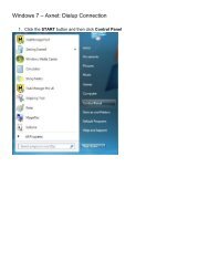
PDA Connection ....................................................................................... 83<br />
Data Transfer Device ....................................................................................... (DTD) Connection<br />
85<br />
SEG LAN/WAN ....................................................................................... Connection<br />
106<br />
Dynamic IP ....................................................................................... Address<br />
113<br />
Dynamic IP ....................................................................................... Address, non-expiring lease<br />
117<br />
Static IP Address ....................................................................................... 117<br />
Modem Connection ....................................................................................... 127<br />
Managing Stand-Alone ....................................................................................... Controllers<br />
129<br />
<strong>IEI</strong> <strong>Hub</strong> <strong>Manager</strong> <strong>Professional</strong> <strong>v8</strong>
Contents<br />
5 Time Zones ....................................................................................... 131<br />
6 Doors ....................................................................................... 134<br />
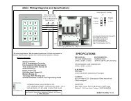
HC500, <strong>Hub</strong>+\Max, ....................................................................................... Max 2 v1 and Max 2 v2<br />
149<br />
prox.pad plus ....................................................................................... IR<br />
150<br />
prox.pad plus, ....................................................................................... Max 3 v1 and Max 3 v2<br />
152<br />
LS2\P ....................................................................................... 160<br />
Door Wizard ....................................................................................... 161<br />
7 Access Levels ....................................................................................... 162<br />
8 Access Level Wizard ....................................................................................... 169<br />
9 Users ....................................................................................... 172<br />
User Import Wizard ....................................................................................... 195<br />
Add User Group ....................................................................................... 198<br />
10 Holidays ....................................................................................... 200<br />
Chapter 7: Communications<br />
Chapter 8: Tools<br />
12 Options<br />
Chapter 9: Reports<br />
1 Communications ....................................................................................... Menu<br />
204<br />
2 Security Chip ....................................................................................... 204<br />
3 Import Door Settings ....................................................................................... 204<br />
4 Import\Export Doors ....................................................................................... 205<br />
5 Network Query ....................................................................................... 209<br />
6 System Dashboard ....................................................................................... 211<br />
1 Tools Menu ....................................................................................... 216<br />
2 Log Archiving ....................................................................................... 216<br />
3 Audit Archiving ....................................................................................... 217<br />
4 Database Backup/Restore<br />
....................................................................................... 218<br />
5 Database Conversion ....................................................................................... Utility<br />
220<br />
6 Run COM Port Test ....................................................................................... 223<br />
7 Scheduled Log ....................................................................................... Import<br />
224<br />
8 Scheduled Log ....................................................................................... Import Reminder<br />
225<br />
9 Table Initialization ....................................................................................... 226<br />
10 Application Initialization ....................................................................................... 227<br />
11 Indexing ....................................................................................... 228<br />
....................................................................................... 230<br />
1 Reports Menu ....................................................................................... 235<br />
2 Printer Options ....................................................................................... 235<br />
3 Log Filter ....................................................................................... 236<br />
4 Time Management ....................................................................................... 240<br />
5 Misc. Log Reports<br />
....................................................................................... 244<br />
II
III<br />
<strong>IEI</strong> <strong>Hub</strong> <strong>Manager</strong> <strong>Professional</strong> <strong>v8</strong><br />
Chapter 10: Help<br />
6 Assignment Reports ....................................................................................... 245<br />
7 Database ....................................................................................... 252<br />
8 Audit ....................................................................................... 254<br />
9 Archive Viewer ....................................................................................... 254<br />
10 Generate Data ....................................................................................... for External Report Writer<br />
256<br />
11 Scheduled Log ....................................................................................... Import Errors<br />
256<br />
1 Help ....................................................................................... 257<br />
2 Online Support ....................................................................................... 257<br />
3 Check for Updates ....................................................................................... 257<br />
4 Check for Custom ....................................................................................... Updates<br />
259<br />
5 Upgrading <strong>Hub</strong> ....................................................................................... <strong>Manager</strong> <strong>Professional</strong><br />
260<br />
6 About ....................................................................................... 261<br />
7 Glossary ....................................................................................... 263<br />
Chapter 11: Obtaining Technical Support<br />
1 Obtaining Technical ....................................................................................... Support<br />
265<br />
Chapter 12: Copyright Information<br />
1 Copyright Information ....................................................................................... 266<br />
Index 267<br />
<strong>IEI</strong> <strong>Hub</strong> <strong>Manager</strong> <strong>Professional</strong> <strong>v8</strong>
Chapter 1: Using Online Help<br />
1.1 Using Help<br />
<strong>IEI</strong> <strong>Hub</strong> <strong>Manager</strong> <strong>Professional</strong> <strong>v8</strong><br />
Chapter 1: Using Online Help<br />
Hardcopy Version<br />
Some references in this manual are designed for use with the electronic version. The<br />
electronic PDF version can be found in the following folder:<br />
C:\Program Files\<strong>IEI</strong>\HMP8\Manual.exe<br />
If you did not install <strong>Hub</strong> <strong>Manager</strong> <strong>Professional</strong> to the default location, then browse to<br />
the custom installation folder you specified during install:<br />
\<strong>IEI</strong>\HMP8\Manual.exe<br />
Electronic Version<br />
The electronic help system provided with <strong>Hub</strong> <strong>Manager</strong> <strong>Professional</strong> quickly displays<br />
instructions about the software when you select the Help item from the menu bar or by<br />
pressing F1. You can obtain this online help without interrupting the work you are doing<br />
and without looking through a paper manual.<br />
In addition, this help system is context sensitive, meaning that if you press F1 while any<br />
screen is open the section pertaining to that feature is displayed. For example if you are in<br />
the User edit screen, then press F1, the help file opens to the users section.<br />
NOTE: Some utilities may not have F1 functionality.<br />
After the <strong>Hub</strong> <strong>Manager</strong> <strong>Professional</strong> Online Help window opens, you'll see a choice of<br />
tabs: Contents, Index, Search and Favorites<br />
· Select the Contents tab to browse through topics by category, much like the<br />
Table of Contents to a book.<br />
· Select the Index tab to see a list of index entries: either type the word you're<br />
looking for or scroll through the list.<br />
· Select the Find tab to search for words or phrases that may be contained in a<br />
Help topic.<br />
· Select the Favorites tab to save a bookmark to certain Help topics for quick<br />
reference at a later time.<br />
1
2<br />
Chapter 2: Foreword<br />
Chapter 2: Foreword<br />
About This Manual<br />
This manual is designed for users of <strong>IEI</strong> <strong>Hub</strong> <strong>Manager</strong> <strong>Professional</strong> <strong>v8</strong> software in<br />
conjunction with HC500, <strong>Hub</strong>+\Max, Max 2 v1, Max 2 v2, LS2\P, Max 3 v1, Max 3 v2,<br />
prox.pad plus IR and prox.pad plus controllers. All installation, setup, operational<br />
information and procedures, accompanying screen captures and other relevant<br />
material is contained in this manual.<br />
Safety Warnings and Cautions<br />
When handling a printed circuit board, to guard against possible static discharges,<br />
touch a grounded object BEFORE touching the board. Static shock can render the<br />
product unusable.<br />
Disclaimer<br />
Due to design changes and product improvements, information in this manual is<br />
subject to change without notice. <strong>IEI</strong> assumes no responsibility for any errors that<br />
may appear in this manual.<br />
Reproduction<br />
Neither this manual nor any part of it may be reproduced, photocopied, or<br />
electronically transmitted in any way without the written permission of <strong>IEI</strong>.<br />
Technical Support<br />
Should you experience any difficulty installing or operating the <strong>Hub</strong> <strong>Manager</strong><br />
<strong>Professional</strong> software, please contact your installation/service company or <strong>IEI</strong> at 800-<br />
343-9502.<br />
Using this Manual<br />
This manual, your reference to the <strong>Hub</strong> <strong>Manager</strong> <strong>Professional</strong> software,<br />
accompanies the <strong>Hub</strong> <strong>Manager</strong> <strong>Professional</strong> software installed with your access<br />
control system. This manual contains the following topic sections, along with others.<br />
Installation<br />
This section discusses the procedure for installation <strong>Hub</strong> <strong>Manager</strong> <strong>Professional</strong><br />
software, the PDA software and the DTD Printer Utility software.<br />
Overview<br />
This section provides a description of this software's functionality.<br />
System<br />
This section explains the menu choices available on the System menu.<br />
<strong>IEI</strong> <strong>Hub</strong> <strong>Manager</strong> <strong>Professional</strong> <strong>v8</strong>
Database<br />
This section describes the various program databases.<br />
<strong>IEI</strong> <strong>Hub</strong> <strong>Manager</strong> <strong>Professional</strong> <strong>v8</strong><br />
Chapter 2: Foreword<br />
Communications<br />
This section details how to use the 'Export to Doors' and 'Import Transaction Log'<br />
functions.<br />
Tools<br />
This section details the Tools menu options.<br />
Reports<br />
This section supplies procedure for selecting the various types of available reports and<br />
shows examples of each.<br />
Obtaining Technical Support<br />
This section describes how to obtain technical support for this software, and how to<br />
prepare to make a technical support request.<br />
Glossary<br />
This section contains commonly used terms and definitions.<br />
Manual Conventions: Keys, Selections, and Commands<br />
The type style, terminology, and references to important information used in this manual<br />
are intended to make the manual easy to use. The following sections describe these<br />
conventions.<br />
The following terms are used to indicate commands, which you must execute, or<br />
selections you must make, using the mouse or keyboard.<br />
Bold Face Italicized Type<br />
Text that is both written in bold face and italicized type corresponds directly to text<br />
that appears in the software.<br />
<br />
Keyboard keys you must press are contained within carets.<br />
<br />
Represents a Windows accelerator key or combination key you must press. Hold<br />
down the key, and then press the indicated key.<br />
3
4<br />
Chapter 2: Foreword<br />
Click<br />
The Click command means you must click the LEFT mouse button once, unless the<br />
right mouse button is indicated (as in Right-Click). [For command buttons, you can<br />
also use the Windows accelerator key ( plus the underlined character)<br />
associated with the item to activate the item. For example, the accelerator key for the<br />
Start menu's Run... command is +R.]<br />
Double-Click<br />
Indicates two rapid clicks of the left mouse button. [You can also select the specified<br />
item by highlighting it (using the arrow keys or key), pressing the space bar to<br />
select it, then pressing the key.]<br />
Select or Highlight<br />
Select or highlight an item by clicking on it or by using the TAB key to bring focus to a<br />
component and then acting upon that component by pressing the key or<br />
the SPACEBAR.<br />
Press<br />
Press the specified key or keys on the keyboard.<br />
Drag<br />
The Drag command follows standard Windows usage: select the desired item, click<br />
and hold down the left mouse button, move the mouse pointer to the desired location,<br />
then release the mouse button.<br />
Menu Selections<br />
When a series of two or more menu choices is presented, the menu commands are<br />
separated by a right facing caret like this: System > Login. A menu choice is always<br />
specified by its complete choice path. That is, the Main menu selection is given first,<br />
along with any subsequent menu selections needed to get to the final menu choice.<br />
For example, Database > Doors means first choose Database from the Main menu,<br />
then choose Doors.<br />
<strong>IEI</strong> <strong>Hub</strong> <strong>Manager</strong> <strong>Professional</strong> <strong>v8</strong>
<strong>IEI</strong> <strong>Hub</strong> <strong>Manager</strong> <strong>Professional</strong> <strong>v8</strong><br />
Chapter 2: Foreword<br />
Save, Cancel, and Done Commands<br />
Most screens and\or dialog boxes contain two command buttons that are used to<br />
close the dialog box: Save and Cancel.<br />
When you select the Save button, the program saves the current data or settings and<br />
returns to the previous screen.<br />
When you select the Cancel button, the program discards any and all edits and then<br />
returns you to the previous screen.<br />
A Done button will be displayed when no data is being edited, such as when you are<br />
viewing one of the directories: Sites, Time Zones, Doors, Access Levels, Users,<br />
Holidays or Operators. When you select the Done button, the program will simply<br />
close the current screen (window) and return you to the main screen of <strong>Hub</strong><br />
<strong>Manager</strong> <strong>Professional</strong>.<br />
Window Types<br />
This software uses Microsoft Windows conventions and terminology regarding how<br />
information is presented on screen. In general, information is displayed in bordered<br />
windows called dialog boxes, or windows, or screens, or forms. For further information,<br />
refer to the Microsoft Windows documentation.<br />
Window or Dialog Type Description<br />
Application dialog used for operator data entry, or to present information for operator<br />
selection; usually referenced by the title of the application dialog, such as Password<br />
dialog.<br />
Confirmation dialog<br />
Presents the OK or Cancel command button choices to accept or reject an action.<br />
Main window<br />
Displays initially whenever the software starts up; contains a menu and command<br />
buttons that provide access to program functions.<br />
Message box<br />
Presents information that the operator must acknowledge.<br />
Dialog Tabs<br />
Some dialog windows or boxes use a tabbed display to categorize information.<br />
Selecting a tab displays the information or data entry items associated with that tab.<br />
The location of such information is referred to by the name of the tab, such as the<br />
Door Settings tab or the Time Zones tab.<br />
5
6<br />
Chapter 3: Installation<br />
Chapter 3: Installation<br />
3.1 Installation<br />
This section provides a general description of the <strong>IEI</strong> <strong>Hub</strong> <strong>Manager</strong> <strong>Professional</strong> <strong>v8</strong><br />
software. It also supplies procedures for installing or using various <strong>Hub</strong> <strong>Manager</strong><br />
<strong>Professional</strong> <strong>v8</strong> software components. <strong>Hub</strong> <strong>Manager</strong> <strong>Professional</strong> is an access control<br />
management program for Microsoft Windows operating systems used in conjunction with<br />
<strong>IEI</strong>'s access control equipment.<br />
If you are upgrading from a previous version of <strong>Hub</strong> <strong>Manager</strong> <strong>Professional</strong> please go to<br />
the Upgrading <strong>Hub</strong> <strong>Manager</strong> <strong>Professional</strong> section of this manual.<br />
Operating Systems<br />
<strong>Hub</strong> <strong>Manager</strong> <strong>Professional</strong> is qualified to work on Windows XP Home, XP <strong>Professional</strong>,<br />
Vista Home Premium, Vista Business, Server 2003 Standard, Server 2003 Enterprise,<br />
Server 2008 Standard and Server 2008 Enterprise only. If you are not running one of<br />
these supported operating systems, the software installation will be denied.<br />
NOTE: All software must be installed using a Windows Administrator user account.<br />
The program can be used by a standard Windows logon but requires an Administrator<br />
to grant that user account full read/write access to the following folders and files:<br />
· \<strong>IEI</strong>\HMP8\ (default is C:\Program Files\<strong>IEI</strong>\HMP8)<br />
· C:\Program Files\Common Files\Borland Shared\<br />
· C:\PDOXUSRS.NET<br />
Installing the <strong>Hub</strong> <strong>Manager</strong> <strong>Professional</strong> software onto the PC<br />
Follow the steps below to install <strong>Hub</strong> <strong>Manager</strong> <strong>Professional</strong> onto your PC.<br />
1. Insert the installation CD.<br />
NOTE: On most computers, the Autorun program launches automatically. If it<br />
doesn't, select Start > Run, browse to the CD-ROM drive, select the<br />
Autorun.exe file, then select Open and OK.<br />
<strong>IEI</strong> <strong>Hub</strong> <strong>Manager</strong> <strong>Professional</strong> <strong>v8</strong>
<strong>IEI</strong> <strong>Hub</strong> <strong>Manager</strong> <strong>Professional</strong> <strong>v8</strong><br />
Chapter 3: Installation<br />
2. Select Install <strong>Hub</strong> <strong>Manager</strong> <strong>Professional</strong> <strong>v8</strong>, which is the top choice on the<br />
screen. You are then prompted with a confirmation screen stating the files for<br />
<strong>Hub</strong> <strong>Manager</strong> <strong>Professional</strong> will be installed. Click Yes to continue.<br />
3. When the setup Welcome screen appears, click Next to continue to display<br />
the License Agreement. Use the scroll bar to read through the License<br />
Agreement, then select I accept the agreement to indicate your acceptance<br />
and click the Next button.<br />
4. Next you are prompted to a Select Destination Location to install the<br />
program. The default location is C:\Program Files, but you are allowed to install<br />
<strong>Hub</strong> <strong>Manager</strong> <strong>Professional</strong> to any folder you choose, on your local PC.<br />
NOTE: Do not attempt to install the software on removable media, a<br />
network drive or directly to the root of a local drive (ie. do not install<br />
directly to D:\, but D:\Programs).<br />
5. After choosing your installation location, click OK to proceed with the<br />
installation. The next screen you are presented with shows a progress bar and<br />
various files being copied to your PC.<br />
6. Once the progress bar is complete, the Information screen appears,<br />
containing the software Release Notes, which is the ReadMe file included in<br />
the installation folder. Please read the ReadMe file because it contains the<br />
most up to date information about new features and important changes to the<br />
7
8<br />
Chapter 3: Installation<br />
software.<br />
7. Click Next to continue, then click Finish on the final screen to complete the<br />
<strong>Hub</strong> <strong>Manager</strong> <strong>Professional</strong> <strong>v8</strong> software installation.<br />
LS Link Installation<br />
LS Link is qualified to work on Windows XP Home and XP <strong>Professional</strong> only. If you are<br />
not running one of these supported operating systems, the PDA software<br />
installation will be denied. PDA's are not supported by <strong>Hub</strong> <strong>Manager</strong><br />
<strong>Professional</strong> when installed on Windows Vista, Windows Server 2003 or Windows<br />
Server 2008.<br />
NOTE: Refer to the PDA Software section for additional details about using LS Link.<br />
System Requirements<br />
The following is a list of required equipment in order to use LS Link:<br />
· <strong>IEI</strong>'s <strong>Hub</strong> <strong>Manager</strong> <strong>Professional</strong> <strong>v8</strong> software<br />
· Windows XP Home or Windows XP <strong>Professional</strong> Operating System<br />
· PDA with Palm OS 3.5, 4.x, or 5.x<br />
· Palm Desktop and HotSync <strong>Manager</strong> software (provided by PDA vendor)<br />
· 250KB of available memory on the PDA for each controller you are managing<br />
IMPORTANT NOTE FOR CURRENT PDA APPLICATION USERS: If you are currently<br />
using a version of the PDA application that was distributed with a version of PC<br />
software that was released prior to <strong>Hub</strong> <strong>Manager</strong> <strong>Professional</strong> <strong>v8</strong>, then you must<br />
install the latest version of the PDA application that ships with <strong>Hub</strong> <strong>Manager</strong><br />
<strong>Professional</strong> <strong>v8</strong>. Use of the previous version of PDA software will result in incorrect<br />
operation. The version of PDA software you must have to operate with <strong>Hub</strong> <strong>Manager</strong><br />
<strong>Professional</strong> <strong>v8</strong> must be version 4 or greater. To check your version of PDA software,<br />
go to the main screen of the PDA software, and tap the title bar at the top of the<br />
screen to open the Help menu. Select About to display the software version number. If<br />
this number is less than 4, then you must install LS Link from the <strong>Hub</strong> <strong>Manager</strong><br />
<strong>Professional</strong> <strong>v8</strong> installation CD as detailed below.<br />
Installation Procedure:<br />
NOTE: On most computers, the Autorun program launches automatically. If it does<br />
not, select Start > Run, browse to the CD-ROM drive, select the Autorun.exe file,<br />
then select Open and OK.<br />
1. Select Install LS Link.<br />
2. The install program displays a confirmation screen to remind you that Palm<br />
Desktop and HotSync <strong>Manager</strong> software must be installed prior to installing LS<br />
<strong>IEI</strong> <strong>Hub</strong> <strong>Manager</strong> <strong>Professional</strong> <strong>v8</strong>
<strong>IEI</strong> <strong>Hub</strong> <strong>Manager</strong> <strong>Professional</strong> <strong>v8</strong><br />
Chapter 3: Installation<br />
Link software. In addition, if either of these applications are running, the<br />
installation asks if you want it to turn them off for you, because the install won't<br />
continue until both applications are closed.<br />
3. Select OK.<br />
4. Select the individual PDA's you want to install the PDA application onto or<br />
check the Install onto all PDA's checkbox to install the application onto all of<br />
the PDA's in the system. Click Install to continue.<br />
5. If Palm Desktop is not found in the standard Palm installation folder, the<br />
following message appears. Click OK to close the message, then browse the<br />
to the Palm Desktop program folder, where Palm.exe is located.<br />
9
10<br />
Chapter 3: Installation<br />
6. When PC portion of the installation is complete, the following screen appears.<br />
7. Finally, HotSync with each PDA that you selected above. When the HotSync<br />
process is complete, the PDA application's logo appears on the main screen of<br />
those PDA's, as shown below.<br />
<strong>IEI</strong> <strong>Hub</strong> <strong>Manager</strong> <strong>Professional</strong> <strong>v8</strong>
<strong>IEI</strong> <strong>Hub</strong> <strong>Manager</strong> <strong>Professional</strong> <strong>v8</strong><br />
Chapter 3: Installation<br />
DTD Printer Utility Software Installation<br />
This DTD Printer Utility is designed for use with the Data Transfer Device operating in<br />
Printer Mode, which is available in firmware version 00.40 or later. When the DTD is in<br />
Printer Mode it's used to capture infrared printer data from products supporting the infrared<br />
dump feature. The DTD Printer Utility retrieves this data from the DTD and stores it in a<br />
text file on your PC. This software is installed and used separately from the <strong>Hub</strong><br />
<strong>Manager</strong> <strong>Professional</strong> software and separate from the LS Link software. It is not required<br />
for using the DTD within the <strong>Hub</strong> <strong>Manager</strong> <strong>Professional</strong> software.<br />
The DTD Printer Utility is qualified to work on Windows XP Home, XP <strong>Professional</strong>, Vista<br />
Home Premium, Vista Business, Server 2003 Standard, Server 2003 Enterprise, Server<br />
2008 Standard and Server 2008 Enterprise only. If you are not running one of these<br />
supported operating systems, the software installation will be denied.<br />
NOTE: Refer to the Data Transfer Device (DTD) Connection section for additional<br />
details about using the DTD hardware.<br />
Installation Procedure<br />
1. Insert the installation CD<br />
NOTE: On most computers, the Autorun program launches automatically. If it<br />
doesn't, select Start > Run, browse to the CD-ROM drive, select the Autorun.<br />
exe file, then select Open and OK.<br />
2. Select the Install DTD Printer Utility option.<br />
3. When the setup Welcome screen appears, click Next to continue to display<br />
the License Agreement. Use the scroll bar to read through the License<br />
Agreement, then select I accept the agreement to indicate your acceptance<br />
and click the Next button.<br />
4. Next you are prompted to Select Destination Location to install the program.<br />
The default location is C:\Program Files, but you are allowed to install the DTD<br />
Printer Utility to any folder you choose, on your local PC.<br />
NOTE: Do not attempt to install the software on removable media, a<br />
network drive or directly to the root of a local drive (ie. do not install<br />
directly to D:\, but D:\Programs).<br />
5. After choosing your installation location, click OK to proceed with the<br />
installation. The next screen you are presented with shows a progress bar and<br />
various files being copied to your PC.<br />
6. Once the progress bar is complete, a screen indicating the installation is<br />
complete appears. Click Finish on the final screen to complete the DTD Printer<br />
Utility software installation.<br />
11
12<br />
Chapter 3: Installation<br />
<strong>IEI</strong> <strong>Hub</strong> <strong>Manager</strong> <strong>Professional</strong> <strong>v8</strong>
Using the DTD Printer Utility<br />
<strong>IEI</strong> <strong>Hub</strong> <strong>Manager</strong> <strong>Professional</strong> <strong>v8</strong><br />
Chapter 3: Installation<br />
Once you've installed the DTD Printer Utility you can start it by going to the Windows<br />
Start Menu and browse to the DTD Printer Utility v1.0 folder in your program list, then<br />
click DTD Printer Utility. You can also double-click on the desktop icon. Once<br />
launched, the screen below appears.<br />
13
14<br />
Chapter 3: Installation<br />
Before using the DTD Printer Utility, you must select the Com Port that you plugged<br />
the DTD into. Since this is a USB device, Windows automatically assigns it a Com<br />
port. You now have to find out the Com port number. See the Data Transfer Device<br />
(DTD) Connection section for more information on determining the Com port number<br />
that was assigned. Once selected, this Com port is automatically selected the next<br />
time you run the software.<br />
To retrieve the infrared printer logs from the DTD click on Get All Infrared Printer<br />
Logs from DTD. The software then imports the files to your PC. You can see the files<br />
it imported on left side under Available Log Files. The right hand side under Log File<br />
Contents shows the content of each file, when you select it.<br />
To print a log file, select the file on the left, then click the Print button. When you click<br />
the button, the file is immediately printed using your PC's default printer. You can also<br />
print files using any other text editing program, such at Notepad or Wordpad. Open<br />
the text editor, then browse to the DTD Printer Utility\LogFiles folder (located in the<br />
installation location you chose when you installed the software and print the file.<br />
To remove the printer log files from the DTD click on Erase All Infrared Printer logs<br />
from DTD. Please note this only removes printer files and does not delete any files<br />
created in DTD mode using <strong>Hub</strong> <strong>Manager</strong> <strong>Professional</strong> software, including export<br />
files and transaction log files.<br />
To change modes on the DTD:<br />
1. Power on the DTD.<br />
2. Go to the main menu by pressing the 5 key on the DTD.<br />
3. Select STATUS.<br />
4. Select SET MODE.<br />
5. Move the cursor to the desired mode setting and then press the ENTER (5 key)<br />
to set the current mode.<br />
6. Press the back arrow or the * key to return to the main welcome screen.<br />
For quick reference, the current mode is displayed at the top on the main menu on the<br />
DTD.<br />
<strong>IEI</strong> <strong>Hub</strong> <strong>Manager</strong> <strong>Professional</strong> <strong>v8</strong>
Chapter 4: Overview<br />
4.1 General Overview<br />
<strong>IEI</strong> <strong>Hub</strong> <strong>Manager</strong> <strong>Professional</strong> <strong>v8</strong><br />
Chapter 4: Overview<br />
Additional information not contained in this manual may be found in the ReadMe.txt file<br />
located at:<br />
Start > Programs > <strong>Hub</strong> <strong>Manager</strong> Pro <strong>v8</strong> > ReadMe<br />
Operating Systems<br />
<strong>Hub</strong> <strong>Manager</strong> <strong>Professional</strong> is qualified to work on Windows XP Home, XP <strong>Professional</strong>,<br />
Vista Home Premium, Vista Business, Server 2003 Standard, Server 2003 Enterprise,<br />
Server 2008 Standard and Server 2008 Enterprise systems only.<br />
NOTE: All software must be installed using a Windows Administrator user account.<br />
The program can be used by a standard Windows logon but requires an Administrator<br />
to grant that user account full read/write access to the following folders and files:<br />
· \<strong>IEI</strong>\HMP8\ (default is C:\Program Files\<strong>IEI</strong>\HMP8)<br />
· C:\Program Files\Common Files\Borland Shared\<br />
· C:\PDOXUSRS.NET<br />
Major Features in <strong>Hub</strong> <strong>Manager</strong> <strong>Professional</strong> <strong>v8</strong><br />
Operator Logon and Password Security<br />
<strong>Hub</strong> <strong>Manager</strong> <strong>Professional</strong> requires you to login to the software using an operator<br />
name and password. You can create up to a maximum of 99 operators in the<br />
software with each assigned a unique set of privileges. You can assign operators with<br />
full access, read only access or no access to specific areas of the software. The<br />
default login in name is HUBMAN and the default password is HUBMAN. <strong>IEI</strong><br />
recommends that you change the default login information immediately after<br />
installing the software. You should also change your password periodically.<br />
Remember, that the name and password are case sensitive.<br />
Main Menu Screen<br />
From the main screen you can access each area of the software used to setup and<br />
configure your access control system. You can use either the toolbar buttons or the<br />
main menu options at the top to access each area of the software.<br />
15
16<br />
Chapter 4: Overview<br />
Sites<br />
A Site is a group of similar controllers with a common connection type. <strong>Hub</strong><br />
<strong>Manager</strong> <strong>Professional</strong> can hold up to 1,000 sites containing a limited number of<br />
doors based on the controller type you select. If you have more doors than a site<br />
allows, then you must create another site and add the additional doors to the second<br />
site. The chart below contains the maximum number of doors allowed per Site,<br />
depending on the controller type.<br />
Controller Type Maximum Doors Allowed Per Site<br />
HC500 64<br />
<strong>Hub</strong>+\Max 64<br />
Max 2 v1 64<br />
Max 2 v2 64<br />
LS2\P 300<br />
prox.pad plus 64<br />
Max 3 v1 64<br />
Max 3 v2 64<br />
prox.pad plus IR 300<br />
Access Levels<br />
Access Levels are used to link the users in the database to each door controller. This<br />
is also where you define which doors each user has access to, the user type (such as<br />
standard, passage, etc), access condition (code OR card; code AND card) and the<br />
Time Zones during which the user is allowed access. You use Access Levels to group<br />
users together that have similar access privileges. Access Levels allow you to modify<br />
a group of users, rather than requiring you to edit each user individually. You can<br />
create up to a maximum of 1000 unique Access Levels.<br />
<strong>IEI</strong> <strong>Hub</strong> <strong>Manager</strong> <strong>Professional</strong> <strong>v8</strong>
<strong>IEI</strong> <strong>Hub</strong> <strong>Manager</strong> <strong>Professional</strong> <strong>v8</strong><br />
Chapter 4: Overview<br />
Users<br />
<strong>Hub</strong> <strong>Manager</strong> <strong>Professional</strong> can store a maximum of 20,000 users in the database.<br />
Each door controller can store a limited number of those users, based on the user<br />
capacity of the controller type. When you add a user you specify the user's name,<br />
their code or card information, but you don't directly select the doors the user has<br />
access to. Rather than directly assigning users to door controllers, you assign then to<br />
an Access Level, which determines the doors the user has access to, as described<br />
above.<br />
Default Users<br />
By default, the user database has two pre-defined users: Master User with a code<br />
of 1234 and a Supervisor User with no code defined. These users cannot be<br />
deleted.<br />
In addition to adding users one at a time, <strong>Hub</strong> <strong>Manager</strong> <strong>Professional</strong> offers two<br />
features allowing you to add groups of users:<br />
· Add Group<br />
· User List Import Wizard<br />
Add Group<br />
You can add a group of users with common settings such as access level,<br />
sequential card numbers, and random generation of code using the Add Group<br />
feature.<br />
User List Import Wizard<br />
With the User List Import Wizard you can import a CSV file containing a list of<br />
user names. A CSV file is a simple text file that separates the fields with<br />
commas. This is convenient if you already have a list of users in a separate CSV<br />
file.<br />
Time Zones<br />
Time Zones are used to specify when user's are allowed access. In addition, you can<br />
designate a Time Zone as an Auto-Unlock Time Zone, so the door unlocks on a<br />
schedule. You can create up to a maximum of 1000 unique Time Zones in <strong>Hub</strong><br />
<strong>Manager</strong> <strong>Professional</strong>. Each door controller can store up to eight Time Zones from<br />
that list. The <strong>Hub</strong> <strong>Manager</strong> <strong>Professional</strong> database ships with seven pre-defined<br />
common Time Zones. If these pre-defined Time Zones do not meet your requirements<br />
you can either leave them unused, delete them or edit them to suit your needs.<br />
17
18<br />
Chapter 4: Overview<br />
Auto-Unlock Time Zones<br />
As mentioned above, you can designate a Time Zone as an Auto-Unlock Time Zone.<br />
An Auto-Unlock Time Zone means the door will unlock and relock on a schedule. You<br />
can also enable the First-In Auto-Unlock option, which means the door won't<br />
automatically unlock until a valid user gains access. Of the eight Time Zones that you<br />
can assign to most controller types, each one can be designated as Auto-Unlock.<br />
Refer to the Auto-Unlock section for further details.<br />
Holidays<br />
Holidays are used to determine when a user is allowed access. When you set up a<br />
Time Zone, you must specify whether or not the Time Zone applies to holidays. You<br />
can specify up to 16 single date holidays per system and 16 block holidays per<br />
system (block holidays are not supported by all controller types).<br />
Communications<br />
<strong>Hub</strong> <strong>Manager</strong> <strong>Professional</strong> contains a number of communications options, which are<br />
discussed below.<br />
Exporting to Doors<br />
This is the process used to send data to your door controllers. You have two<br />
options when exporting data. You can choose to either perform a full export, which<br />
sends all the data or to send changes only, which only sends the changes you<br />
made since the last export. The software automatically keeps track of all the<br />
changes you make, so when you choose to export, it knows which doors have<br />
new data.<br />
When you export to controllers for the first time, <strong>IEI</strong> recommends that you perform<br />
a full export, rather than changes only. This recommendation applies to existing<br />
devices as well as new devices. This option ensures that all the data in the<br />
controller is completely synchronized with the database and there is no data that<br />
shouldn't be there.<br />
Export Time/Date<br />
This option allows you to set the time and date in the controllers. You cannot<br />
export the time or date directly to a Handheld connected controller from the PC<br />
software. However, the Handheld device is able to send the time to the controller<br />
using the time and date of the Handheld itself.<br />
For directly connected controllers (if available) the PC's clock is used to set the<br />
time and date. Before you perform this operation, verify that the time and date on<br />
the PC are correct.<br />
<strong>IEI</strong> <strong>Hub</strong> <strong>Manager</strong> <strong>Professional</strong> <strong>v8</strong>
<strong>IEI</strong> <strong>Hub</strong> <strong>Manager</strong> <strong>Professional</strong> <strong>v8</strong><br />
Chapter 4: Overview<br />
Importing Transaction Logs<br />
Each door controller stores it's own transaction event log which the <strong>Hub</strong><br />
<strong>Manager</strong> <strong>Professional</strong> software can import into the database. All new<br />
transaction log data is appended to the existing transaction log data currently<br />
stored in the database. You can use this information to print reports to see activity<br />
from your door controllers.<br />
Scheduled Import of Transaction Logs<br />
<strong>Hub</strong> <strong>Manager</strong> <strong>Professional</strong> contains a feature called Scheduled Log Import,<br />
which allows the system to automatically import the transaction log from your<br />
controller's on a schedule that you define. First, you choose a time you want the<br />
import to occur, then select how often to import. You can specify how many days<br />
between each import, with a minimum of once a day. When the schedule time is<br />
reached, the import process will occur automatically. All new transaction log data<br />
is appended to the existing data. This feature is not available with controllers that<br />
are managed using a handheld device.<br />
NOTE: You must log out, but not exit, for Scheduled Log Import to work<br />
properly. If an operator is logged in to <strong>Hub</strong> <strong>Manager</strong> <strong>Professional</strong> the log<br />
retrieve will not start automatically.<br />
Importing of Door Settings<br />
This features allows you to import all the door settings, including user information,<br />
contained in a door controller. You can use this information to verify the controller<br />
has the correct information or to print the imported data so you can enter it into<br />
the software, in case you have lost your database. This feature is not available<br />
with controllers that are managed via handheld device. Please keep in mind that<br />
Access Level information is not stored in the controllers. If you have lost your<br />
database for some reason, you will have to rebuild your Access Levels prior to<br />
entering the data you retrieved from the controllers using this feature. The best<br />
way to ensure that you maintain your information is to use the built-in backup<br />
feature in <strong>Hub</strong> <strong>Manager</strong> <strong>Professional</strong>.<br />
19
20<br />
Chapter 4: Overview<br />
Network Query<br />
The Network Query feature is used to determine the online status of a connected<br />
controller (either through serial (or USB) com port, modem or SEG connection). In<br />
addition, the Network Query returns the door type and firmware information (if<br />
supported by the controller). Before this feature will function, you must connect to<br />
the Site through the Sites directory using the Connect button. Once the<br />
connected status is indicated, you can use this feature. You must perform this<br />
operation for each Site, if you want to query multiple Sites.<br />
NOTE: This feature is not available when using a Handheld connected<br />
controller.<br />
Transaction Log Reports<br />
Below is a brief explanation of some of the transaction log report features.<br />
Transaction Log Report Filter<br />
This options allows you to customize the transaction log report to show only<br />
those items that meet your filter criteria, such as a date range, a specific user, a<br />
specific access level, any combination of doors or any combination of events.<br />
Archiving Transaction Logs<br />
<strong>Hub</strong> <strong>Manager</strong> <strong>Professional</strong> contains a Log Archiving feature, which is used to<br />
archive your current transaction log. To use this feature go to Tools > Log<br />
Archiving. The archive file is stored in CSV format in a folder of your choice. You<br />
can open a CSV file with Microsoft Excel or other CSV viewing program. Once<br />
you perform this operation, the log events are removed from the <strong>Hub</strong> <strong>Manager</strong><br />
<strong>Professional</strong> database, stored in the archive file and are no longer available in the<br />
Log Filter report. To view the data within <strong>Hub</strong> <strong>Manager</strong> <strong>Professional</strong> use the<br />
Archive Viewer feature.<br />
Misc. Log Reports<br />
Three types of pre-defined reports are available. The first report type lets you see<br />
the very first and very last events on a particular day for each door controller. The<br />
second report type allows you to see a list of the different days that a particular<br />
user had used the access control system. The last report type shows all the<br />
users that used the access control system on a particular day.<br />
<strong>IEI</strong> <strong>Hub</strong> <strong>Manager</strong> <strong>Professional</strong> <strong>v8</strong>
<strong>IEI</strong> <strong>Hub</strong> <strong>Manager</strong> <strong>Professional</strong> <strong>v8</strong><br />
Chapter 4: Overview<br />
Time Management Report<br />
The Time Management report is used to calculate how long a user was inside the<br />
protected area during a given time period. This report includes both total time<br />
(gross time) over a given period, as well as, the total time minus any time outside<br />
the building during the same time period (clear time). This report requires<br />
controllers that can produce both User IN and User OUT events. If the controllers<br />
in the system do not have both events, this report can not calculate the amount of<br />
time a user was in the building. See Time Management for more details.<br />
Database Tools<br />
<strong>Hub</strong> <strong>Manager</strong> <strong>Professional</strong> contains the following database tools, which can assist<br />
you in managing your data.<br />
Database Table Initialization<br />
WARNING: Performing this operation will result in data loss. Please perform a<br />
backup before performing this operation.<br />
The Table Initialization feature is used to place the database back to an out-of-box<br />
initialized state. You have three database options to choose from: Database ,<br />
Transaction Log and Audit Trail. The Database option, initializes all your<br />
access control data, including users, doors, access levels, etc. The Transaction<br />
Log option initializes your transaction event log data. The Audit Trail option<br />
initializes the audit trail database table. When you perform this operation, all data<br />
relating the option you choose is removed. This data cannot be retrieved again. It<br />
is recommended that you perform a database backup, as discussed below, prior<br />
to initializing any database.<br />
Database Backup<br />
Use this feature to create a backup of your existing databases to avoid losing your<br />
data. You can then copy these backup files to removable media or other location<br />
off the local PC. If the computer's hard drive crashes, you could then reinstall <strong>Hub</strong><br />
<strong>Manager</strong> <strong>Professional</strong> and then copy the backup files back to your local PC<br />
then restore the database.<br />
Database Restore<br />
This feature allows you to restore your <strong>Hub</strong> <strong>Manager</strong> <strong>Professional</strong> database<br />
from your backup files, discussed above. With this feature, you can easily recover<br />
from a hard drive crash or simply go back to a previous version of your database.<br />
21
22<br />
Chapter 4: Overview<br />
Database Conversion<br />
The Database Conversion Utility is used to convert/migrate your data from any<br />
previous version of <strong>Hub</strong> <strong>Manager</strong> <strong>Professional</strong> to the latest version of <strong>Hub</strong><br />
<strong>Manager</strong> <strong>Professional</strong>. You would use this feature after upgrading to the latest<br />
version. This utility program is run from Tools > Database Conversion Utility.<br />
Database Reports<br />
The following two database reports are available in <strong>Hub</strong> <strong>Manager</strong> <strong>Professional</strong>.<br />
Assignment Reports<br />
Assignment Reports are a collection of reports that show which items are<br />
assigned to other items, such as which access levels contain certain doors or<br />
which users are assigned to certain doors.<br />
Database Reports<br />
These reports shows all programmed items within a certain database table. You<br />
select, for example, to print a report of all the users in the database.<br />
Operator Audit Trail<br />
The software maintains a time/date-stamped audit trail of most activities performed by<br />
the operators within <strong>Hub</strong> <strong>Manager</strong> <strong>Professional</strong>. This includes which operator logged<br />
in, a brief description of the screens that operator accessed and a brief description of<br />
what the operator did in each screen. The report does not give details about exactly<br />
what the operator did, but it does show what areas the operator made a change in.<br />
You can't produce a customized report within the <strong>Hub</strong> <strong>Manager</strong> <strong>Professional</strong><br />
software itself, but you can send it to a file and open the data in another program such<br />
as Microsoft Excel or Crystal Reports.<br />
Operator Audit Trail Archiving<br />
This feature provides the ability to archive the audit trail database table. This<br />
removes the data from the database and stores it in CSV format in a location of<br />
your choice, for later viewing.<br />
Help File<br />
The help, which you are reading now, is available in both electronic PDF and CHM<br />
format, as well as, in hard copy form. To access the help file, simply press the F1 key<br />
or go to the Help menu.<br />
<strong>IEI</strong> <strong>Hub</strong> <strong>Manager</strong> <strong>Professional</strong> <strong>v8</strong>
4.2 Initial Set Up<br />
<strong>IEI</strong> <strong>Hub</strong> <strong>Manager</strong> <strong>Professional</strong> <strong>v8</strong><br />
Chapter 4: Overview<br />
Organizing for <strong>Hub</strong> <strong>Manager</strong> <strong>Professional</strong> Access Control<br />
Getting ready for programming your access control system is a simple matter, as the<br />
software employs the concept of "facility work groups-schedules" for access control. This<br />
section describes the concepts involved and provides relevant procedures.<br />
Facility Work Groups<br />
To create and control electronic access for each door in your facility, the <strong>Hub</strong> <strong>Manager</strong><br />
<strong>Professional</strong> software uses facility work groups; examples include office workers,<br />
supervisors, or work shifts combined with their corresponding normal work times, days,<br />
and the doors they can access normally. This latter idea is known as "Access Levels." It<br />
minimizes required software programming to a simple action of transferring a mirror image<br />
of the existing facility's employee work groups and schedules into the corresponding <strong>Hub</strong><br />
<strong>Manager</strong> <strong>Professional</strong> software screens. Access is granted by issuing each person<br />
access credentials such as a card, RF Fob, Personal Identification Number (PIN), or other<br />
form of credential, and then assigning that person to an identified facility work group<br />
called Access Level (an Access Level is a combination of each person's work group,<br />
doors, times, and days), and then downloading this access level data to the controllers.<br />
Creating Access Levels<br />
1. Create Access Levels by first identifying and grouping employees according to<br />
the following parameters:<br />
· Logical work groups such as office, factory, supervisors, and marketing for<br />
the employees assigned to each work group<br />
· The normal group work schedule for each work group<br />
· The doors that each work group can access<br />
· The times that each work group can access the specified doors<br />
2. Once you finish identifying and grouping employees, transfer this access level<br />
information into the corresponding software screens ("forms") used to program<br />
facility access control parameters into the <strong>Hub</strong> <strong>Manager</strong> <strong>Professional</strong><br />
software.<br />
3. When you finish transferring access level information into the software screens,<br />
download each completed software screen ("form") into the system's<br />
controllers, to control specified door access with Readers and Keypads.<br />
23
24<br />
Chapter 4: Overview<br />
Database Programming Screens ("forms")<br />
The major <strong>Hub</strong> <strong>Manager</strong> <strong>Professional</strong> database programming screens (a.k.a. forms)<br />
include:<br />
Sites<br />
If more than one location is involved, input and identify the additional sites in this form.<br />
Time Zones<br />
Input logical facility work group schedules by days and times.<br />
Holidays<br />
Dates when access can be denied to some and granted to others, based upon the<br />
setup of the Time Zones.<br />
Doors<br />
Identify each controlled door by name and specify a few basic monitoring parameters<br />
here.<br />
Access Levels<br />
Combines the doors and times into an assignable access control structure that can<br />
be assigned to each user.<br />
Users<br />
Assign each employee or visitor an access credential combined with an Access Level<br />
that can control employee or visitor access by door, time, day of week and even<br />
holiday automatically.<br />
<strong>IEI</strong> <strong>Hub</strong> <strong>Manager</strong> <strong>Professional</strong> <strong>v8</strong>
<strong>IEI</strong> <strong>Hub</strong> <strong>Manager</strong> <strong>Professional</strong> <strong>v8</strong><br />
Chapter 4: Overview<br />
Preparing for Access Control Programming<br />
Use normal employee work times to create logical automated access control by group and<br />
doors as follows:<br />
1. For each site in your facility, identify and list all doors to be controlled by name<br />
and location.<br />
Example: Lobby, Computer Room, Accounting, Manufacturing, etc...<br />
2. List the groups of people who work at or regularly visit the facility, their normal<br />
work schedules, and the doors they can access.<br />
Examples:<br />
General Office Workers<br />
8 AM through 6 PM. M-F<br />
Lobby, Employee Entrance, and Computer Room<br />
Names: (List them here)<br />
(First and Last names)<br />
General Supervisors<br />
24 hours a day, 7 days and holidays<br />
All doors<br />
Names: (List them here)<br />
(First and Last names)<br />
Marketing<br />
7 AM through 7 PM M-F<br />
All but Accounting<br />
Names: (List them here)<br />
(First and Last names)<br />
Tech Support<br />
7 AM through 7 PM, M-F<br />
Lobby<br />
Names: (List them here)<br />
(First and Last names)<br />
3. Transfer the information into the <strong>Hub</strong> <strong>Manager</strong> <strong>Professional</strong> software as<br />
described in the Transferring Work Schedule section.<br />
4. Download the access control information to the controllers as described in the<br />
export to doors section.<br />
25
26<br />
Chapter 4: Overview<br />
Preparing Work Schedule<br />
To transfer your current facility's work schedule into the <strong>Hub</strong> <strong>Manager</strong> <strong>Professional</strong><br />
software, follow subsections below.<br />
Preparing Sites<br />
If your system controls more than one site, use the Sites screen in the <strong>Hub</strong> <strong>Manager</strong><br />
<strong>Professional</strong> software to identify each site, identify its controllers, and establish the<br />
necessary information for communications. Programming, reporting, and communication<br />
routes with each site are then linked automatically into the <strong>Hub</strong> <strong>Manager</strong> <strong>Professional</strong><br />
software.<br />
Preparing Time Zones<br />
In the <strong>Hub</strong> <strong>Manager</strong> <strong>Professional</strong> Time Zone programming screen, transfer the times that<br />
reflect the various schedules identified in the previous section.<br />
Example: For Time Zone, fill in each line to reflect each separate possibility of times,<br />
days, and holidays applicable to your employee work schedules.<br />
General Office Workers: 8 AM through 6 PM. M-F<br />
General Supervisors: 24 hours a day, 7 days and holidays<br />
Marketing: 7 AM through 7 PM M-F<br />
Tech Support: 7 AM through 7 PM, M-F<br />
Preparing Doors<br />
In the <strong>Hub</strong> <strong>Manager</strong> <strong>Professional</strong> Door programming screen, transfer each door's<br />
identification into the system by entering the door name and Time zones that are active for<br />
the door. In this screen, enter the activities to be monitored and reported, such as<br />
extended lock timer, auto unlock-relock, forced door, and door ajar (propped door) events.<br />
<strong>IEI</strong> <strong>Hub</strong> <strong>Manager</strong> <strong>Professional</strong> <strong>v8</strong>
<strong>IEI</strong> <strong>Hub</strong> <strong>Manager</strong> <strong>Professional</strong> <strong>v8</strong><br />
Chapter 4: Overview<br />
Preparing Access Levels<br />
As noted earlier, the Access Level concept allows a single-phase entry method for<br />
assigning employees and visitors to the appropriate door and time access control.<br />
1. Using the <strong>Hub</strong> <strong>Manager</strong> <strong>Professional</strong> Access Levels programming screen,<br />
transfer the identified work groups from your list.<br />
2. Assign logical titles for each group's access level by their type of employee<br />
work group.<br />
3. Select appropriate time zones and doors.<br />
Example:<br />
Marketing: 7 AM through 7 PM M-F<br />
All doors but Accounting<br />
4. Create an Access Level titled "Marketing," and then select the appropriate time<br />
zone number(s) and doors that reflect the Marketing" group.<br />
Preparing Users<br />
Using the <strong>Hub</strong> <strong>Manager</strong> <strong>Professional</strong> User screen, fill in the names, access credentials<br />
and select the Access Level (for example, marketing, supervisor). This single step directs<br />
the software to create each employee's access privileges automatically.<br />
Managing and Programming System Alarms<br />
Door Contacts can be monitored, and door ajar (propped door), forced door events<br />
annunciated for response.<br />
1. Define how long each door can remain open before the door open event is<br />
annunciated.<br />
2. Transfer the identified times for each door's information to the Doors screen in<br />
the <strong>Hub</strong> <strong>Manager</strong> <strong>Professional</strong> software.<br />
3. To annunciate a held open or a forced door event, first define the action to be<br />
taken. Examples include "report the event" or "close a relay"; then add this<br />
desired action to the door information.<br />
Providing for a Secure System<br />
This procedure involves defining operators and the respective privileges for each.<br />
1. Define which operators are allowed to program the <strong>Hub</strong> <strong>Manager</strong> <strong>Professional</strong><br />
system and exactly which programming actions each are permitted.<br />
2. Using the Operator screen, specify all tasks/parameters that each operator is<br />
allowed to control, change, report on, or save. Each operator has his/her own<br />
password for logon and then can access only their assigned tasks.<br />
27
28<br />
Chapter 4: Overview<br />
4.3 Menu System<br />
Below is complete list of all the available menu options:<br />
SYSTEM<br />
System <strong>Manager</strong><br />
Login<br />
Logout<br />
Change Password<br />
Exit<br />
DATABASE<br />
Operators<br />
Sites<br />
Time Zones<br />
Doors<br />
Access Levels<br />
Users<br />
Holidays<br />
COMMUNICATIONS<br />
Import Door Settings<br />
Import\Export Doors<br />
Network Query<br />
System Dashboard<br />
TOOLS<br />
Log Archiving<br />
Audit Archiving<br />
Database Backup/Restore<br />
Database Conversion Utility<br />
Run Com Port Test<br />
Scheduled Log Import<br />
Table Initialization<br />
Indexing<br />
Application Initialization<br />
Options<br />
REPORTS<br />
Log Filter<br />
Time Management<br />
Misc Log Reports<br />
Assignment Reports<br />
Database<br />
<strong>IEI</strong> <strong>Hub</strong> <strong>Manager</strong> <strong>Professional</strong> <strong>v8</strong>
Audit<br />
Archive Viewer<br />
Generate Data for External Report Writer<br />
Scheduled Log Import Errors<br />
HELP<br />
Help<br />
Online Support<br />
Check for Updates<br />
Check for Custom Updates<br />
About<br />
System Main Menu Commands<br />
Below is brief description of each main menu option.<br />
<strong>IEI</strong> <strong>Hub</strong> <strong>Manager</strong> <strong>Professional</strong> <strong>v8</strong><br />
Chapter 4: Overview<br />
System<br />
Provides a means of:<br />
· launching the System <strong>Manager</strong> feature which allows you to create, delete, and<br />
switch between other <strong>Hub</strong> <strong>Manager</strong> <strong>Professional</strong> databases you have created<br />
· logging into the program<br />
· logging out of the program<br />
· modifying current login password for the currently logged in operator<br />
· exiting the program<br />
Database<br />
Contains options necessary for setting required system parameters to operate the<br />
door controllers, according to rules established for secure access to protected areas.<br />
Communications<br />
Allows you to export data to the door controllers or import the transaction log from the<br />
door controllers, which documents user activity from individual door controllers, to the<br />
personal computer database.<br />
Tools<br />
Permits you to maintain the program's databases, back up the databases, ensure<br />
proper communications with door controllers, as well as gain access to other utilities.<br />
Reports<br />
Supplies tools for processing and extracting of data from the program's databases,<br />
such as summary forms, user lists, user activity lists, forms, etc...<br />
Help<br />
Supplies access to online help information.<br />
29
30<br />
Chapter 4: Overview<br />
4.4 Running the software<br />
Starting the Software<br />
Once the <strong>Hub</strong> <strong>Manager</strong> <strong>Professional</strong> program is installed successfully, you can start it<br />
in one of two ways:<br />
1. Double-Click the <strong>Hub</strong> <strong>Manager</strong> <strong>Professional</strong> <strong>v8</strong> shortcut icon that the install<br />
program placed on your computer's desktop<br />
2. Browse to the shortcut in the Windows Start Menu <strong>Hub</strong> <strong>Manager</strong><br />
<strong>Professional</strong> <strong>v8</strong> shortcut.<br />
In either case, you are presented with the Login screen, unless you have the auto-login<br />
feature enabled.<br />
NOTE: The first time you start the program, you are prompted to enter support contact<br />
information in a small dialog box. Enter the contact information and select Save to<br />
save it. This information can be changed later by going to Help > About while an<br />
operator is logged in.<br />
Entering Your Login<br />
The default login Name is "HUBMAN" and the default Password is "HUBMAN". Please<br />
note, the Name and Password fields are case sensitive. When you login for the first time<br />
you are logged in under the default operator named HUBMAN. For details about creating<br />
additional operators see the Operators section. For details about changing your password<br />
see the Change Login Password section.<br />
NOTE: If you want the software to auto-login (ie. the software automatically enters<br />
your name and password) go to Tools > Options > General Options. Refer to the<br />
Options section for details.<br />
<strong>IEI</strong> <strong>Hub</strong> <strong>Manager</strong> <strong>Professional</strong> <strong>v8</strong>
<strong>IEI</strong> <strong>Hub</strong> <strong>Manager</strong> <strong>Professional</strong> <strong>v8</strong><br />
Chapter 4: Overview<br />
Navigating through the Program<br />
The following steps describe the path of a typical operator through the software. Your<br />
situation may differ somewhat and depends on the door controller and communication type<br />
you are using.<br />
1. Change the default Login (Name and Password ), as soon as possible, after<br />
installing the <strong>Hub</strong> <strong>Manager</strong> <strong>Professional</strong> software.<br />
2. Review the entire General Overview section to learn the basic concepts about<br />
setting up Sites, Time Zones, Holidays, Doors, Access Levels, and Users.<br />
3. Run the <strong>Hub</strong> <strong>Manager</strong> <strong>Professional</strong> program.<br />
4. Create all of your Sites using Database > Sites.<br />
5. Create the Time Zones required for your system.<br />
6. Create Holidays as applicable.<br />
7. Create Doors and assign the Time-Zones needed in each door controller and<br />
modify any of the default controller configurations as needed.<br />
8. Analyze your system by identifying the common groups of users that have<br />
identical access privileges (Access Levels). Identify the different possible<br />
groups such as managers having 24 hour access to all doors in all sites, a<br />
cleaning crew that only has access on the front doors at certain times of the<br />
day and week, 1st, 2nd, and 3rd shift workers that only have access during<br />
their respective shift periods, normal Monday through Friday 9-5 AM<br />
employees, etc...<br />
9. Go to Access Levels and create the Access Group privileges for that Access<br />
Level based on your analysis.<br />
10.Go to Users and create the names and define the users access credential<br />
fields.<br />
11.Choose Communications > Import\Export Doors to export data to each door<br />
controller in the system.<br />
12.If you are using a DTD to manage your controllers, you must connect the DTD<br />
to the PC prior to running the Import/Export operation. If you are using a PDA to<br />
manage your controllers, you must cradle your PDA and run HotSync after<br />
performing the Import/Export operation. You must then visit each door controller<br />
with the Handheld device. Refer to the PDA Software or Data Transfer Device<br />
(DTD) Connection sections for the details on sending/receiving data. You must<br />
also return to the PC with the Handheld device and perform an import with <strong>Hub</strong><br />
<strong>Manager</strong> <strong>Professional</strong> to complete the process. This final step is required to<br />
let the PC know that you successfully communicated to the controller.<br />
31
32<br />
Chapter 4: Overview<br />
4.5 System Setup Tasklist<br />
Overview<br />
The System Setup Tasklist is displayed to help guide you through the steps needed<br />
to set up a new system.<br />
If you are managing multiple Systems using System <strong>Manager</strong>, then each new System<br />
you create will have a fresh Tasklist, since all of these Tasks are related to each<br />
individual System.<br />
Clicking on any of the blue links will bring you to the specific screen that performs that<br />
action. For example: if you click on the Create Sites link, then the Sites directory will<br />
be opened, where you can then select the Add button to create a new Site.<br />
<strong>IEI</strong> <strong>Hub</strong> <strong>Manager</strong> <strong>Professional</strong> <strong>v8</strong>
<strong>IEI</strong> <strong>Hub</strong> <strong>Manager</strong> <strong>Professional</strong> <strong>v8</strong><br />
Chapter 4: Overview<br />
Once a task is completed, that task will be crossed off the list, the link to that task<br />
will no longer be active, and a checkmark will appear next to it showing you that the<br />
Task is completed.<br />
Inactive links will become active again, if the action that removed that link is no longer<br />
true. For example: if you delete a Site and there are no longer any Sites left in the<br />
System then the Create Sites link will once again become active.<br />
There are some Tasks that do not require that you actually Add an item, but it is<br />
required that you at least visit that screen in order to have that Task seen as<br />
completed. The Tasks that you are required to at least visit are: Create Time Zones,<br />
Create Holidays, and Create Operators. The other Task that is not actually monitored<br />
for success is Export Data to Controllers. Just the act of opening the Export screen is<br />
enough to complete this particular Task.<br />
It is recommended that the Tasks be performed starting with the first Task and ending<br />
with the last Task. Several Tasks require that other Tasks be completed first. In these<br />
cases, you will be brought to the Task that is required. For example: if the very first<br />
Task you select is Create Doors, you will receive a message saying that you must<br />
create a Site before you can add a door, and you will then be brought to the Sites<br />
directory where you should then add a Site.<br />
33
34<br />
Chapter 4: Overview<br />
Once all of the items in the System Setup Tasklist are complete, the list will be<br />
removed from sight. Once the Tasklist is removed, certain actions you perform may<br />
make the Tasklist visible again. These actions include:<br />
· performing a Database Restore from a dataset that does not have all of the<br />
required Tasks completed (Tools > Database Restore)<br />
· performing a Tools > Database Initialization<br />
· enabling the option that says to display the Tasklist even if all tasks are<br />
completed. This option is located at Tools > Options > General.<br />
<strong>IEI</strong> <strong>Hub</strong> <strong>Manager</strong> <strong>Professional</strong> <strong>v8</strong>
4.6 PDA Software<br />
<strong>IEI</strong> <strong>Hub</strong> <strong>Manager</strong> <strong>Professional</strong> <strong>v8</strong><br />
Chapter 4: Overview<br />
LS Link is designed for communications between <strong>Hub</strong> <strong>Manager</strong> <strong>Professional</strong> and <strong>IEI</strong>'s<br />
LS2\P and prox.pad plus IR controllers. These are standalone electronic access control<br />
door controllers that communicate via infrared to a Palm OS PDA. These controllers have<br />
two-way infrared communications capability. By using a PDA and the PDA application,<br />
you can manage your door controllers with <strong>Hub</strong> <strong>Manager</strong> <strong>Professional</strong>.<br />
NOTE: Refer to the Installation section for details about installing the PDA application.<br />
The PDA acts as the connection between <strong>Hub</strong> <strong>Manager</strong> <strong>Professional</strong> and your door<br />
controllers. Using <strong>Hub</strong> <strong>Manager</strong> <strong>Professional</strong> in conjunction with Palm HotSync<br />
<strong>Manager</strong>, you can transfer the data from your PC to your PDA device, then to your door<br />
controller. This process is discussed below.<br />
LS Link System Requirements<br />
The following are a list of required equipment in order to use LS Link:<br />
· <strong>IEI</strong>'s <strong>Hub</strong> <strong>Manager</strong> <strong>Professional</strong> <strong>v8</strong> software<br />
· Windows XP Home or Windows XP <strong>Professional</strong> Operating System<br />
· PDA with Palm OS 3.5, 4.x, or 5.x<br />
· Palm Desktop and HotSync <strong>Manager</strong> software (provided by PDA vendor)<br />
· 250KB of available memory on the PDA for each controller you are managing<br />
NOTE: PDA's are not supported by <strong>Hub</strong> <strong>Manager</strong> <strong>Professional</strong> when installed on<br />
Windows Vista, Windows Server 2003 or Windows Server 2008.<br />
35
36<br />
Chapter 4: Overview<br />
Exporting From <strong>Hub</strong> <strong>Manager</strong> <strong>Professional</strong> to the PDA<br />
When you export to a PDA connected site, <strong>Hub</strong> <strong>Manager</strong> <strong>Professional</strong> creates data files<br />
containing all your controller data and stores this on your PC. You must then run HotSync<br />
<strong>Manager</strong>, which takes those data files and transfers them to your PDA. The following<br />
steps guide you through this process. For additional information, refer to the Export to<br />
Doors section.<br />
1. Choose Communications > Import/Export Doors, enable the Export<br />
Changes Only option, then select the doors you want to export to, if not<br />
already selected. Then press the Start button to create the export data files.<br />
Wait until the entire process is complete before continuing.<br />
NOTE: If you are exporting to a controller for the first time, it is recommended<br />
that you choose Export ALL the data to completely synchronize the<br />
controller hardware with the <strong>Hub</strong> <strong>Manager</strong> <strong>Professional</strong> database. A warning<br />
message is displayed until you choose the Export ALL option. This is done<br />
as a security measure to ensure you are aware that the controller may not<br />
necessarily match your database completely.<br />
2. Next perform the HotSync operation with the PDA.<br />
3. Now take the PDA to each controller and export the data using the Imp/Exp<br />
button in LS Link, and follow the on-screen prompts.<br />
4. When finished with all controllers, go back to the PC and HotSync with the<br />
PDA. Any transaction log data that was imported is now on your PC awaiting<br />
import into <strong>Hub</strong> <strong>Manager</strong> <strong>Professional</strong>.<br />
5. Choose Communications > Import\Export Doors, enable the Import<br />
Transaction Log option, then select the Start button and wait for the import<br />
process to finish.<br />
6. When complete, all data between <strong>Hub</strong> <strong>Manager</strong> <strong>Professional</strong> and the<br />
controller is synchronized.<br />
<strong>IEI</strong> <strong>Hub</strong> <strong>Manager</strong> <strong>Professional</strong> <strong>v8</strong>
<strong>IEI</strong> <strong>Hub</strong> <strong>Manager</strong> <strong>Professional</strong> <strong>v8</strong><br />
Chapter 4: Overview<br />
LS Link automatically handles all existing door data during the HotSync <strong>Manager</strong><br />
process. All door export data from the <strong>Hub</strong> <strong>Manager</strong> <strong>Professional</strong> stored on the PDA<br />
prior to the start of the HotSync <strong>Manager</strong> session is deleted from the PDA memory.<br />
All log event data from the doors stored on the PDA prior to the start of the HotSync<br />
<strong>Manager</strong> session is transferred to the PC for import by <strong>Hub</strong> <strong>Manager</strong> <strong>Professional</strong>.<br />
Once the HotSync <strong>Manager</strong> has completed, run LS Link from the PDA main Screen.<br />
LS Link's main screen has three buttons and a Site drop down list.<br />
The title bar information symbol (in the upper right) is functional in all LS Link screens.<br />
Select the information symbol to display the definitions, descriptions of the features/<br />
functions and data presented in the current screen.<br />
37
38<br />
Chapter 4: Overview<br />
Imp/Exp Button<br />
This button is short for Import/Export and it's used to initiate communications with the<br />
controller. This includes door identification, importing event data from the controller<br />
and exporting new configuration data to the controller.<br />
Files Button<br />
Pressing this button displays the door management screen, which shows you a list of<br />
doors in the current site. This area also provides access to more advanced features.<br />
Any door controller with a check mark in the C column denotes that configuration data<br />
is stored on the PDA that hasn't been sent to the controller. This is useful to know<br />
what doors you still need to visit. Any door controller with a check mark in the L<br />
column denotes that transaction log data is on the PDA that hasn't been transferred to<br />
the PC via a HotSync operation.<br />
Settings Button<br />
This area contains the settings for LS Link.<br />
Site Drop Down List<br />
This drop down list contains an alphabetical list of the Sites with door data currently in<br />
the PDA's memory. The Site shown in the Main Screen is the currently active site. All<br />
operations within LS Link are performed on this active site. When LS Link is launched,<br />
the Site drop down list contains a single entry for each site for which doors were<br />
exported. By default, the first Site in the list is displayed when you first launch the<br />
software.<br />
<strong>IEI</strong> <strong>Hub</strong> <strong>Manager</strong> <strong>Professional</strong> <strong>v8</strong>
<strong>IEI</strong> <strong>Hub</strong> <strong>Manager</strong> <strong>Professional</strong> <strong>v8</strong><br />
Chapter 4: Overview<br />
LS Link Configuration Screen<br />
You can now select a site from the Site drop down list on the Main Screen. If you only<br />
have a single site, it's automatically selected when LS Link is launched. After you select a<br />
Site, select the Settings button to open the Configuration screen. LS Link offers a<br />
number of program preferences that you can select in this screen. These items are global,<br />
which means they influence the way LS Link functions, regardless of what site is selected.<br />
The Configuration screen has several settings: Auto Export Time/Date, Auto<br />
Import Log, Comm Method and Comm Speed. These are discussed below.<br />
Auto Export Time/Date<br />
When selected, LS Link automatically updates the controller's time and date whenever<br />
communication is established. This option is turned on by default, but can be turned<br />
off if you do not want to send the time and date to the controller, for example if you are<br />
crossing a Time Zone boundary and know the time is off.<br />
Auto Import Log<br />
When selected, LS Link automatically retrieves the event log from the device without<br />
prompting you. When this option is not selected, LS Link displays a message box<br />
telling you how many events the device contains and then prompts you to retrieve the<br />
log if you want. This option is turned off by default.<br />
39
40<br />
Chapter 4: Overview<br />
Comm Method<br />
This drop down list allows you to select the specific IR Channel (Infrared) LS Link<br />
requires to function using your PDA. This is required because the various Palm PDA<br />
devices handle IR communication differently and this channel is tailored for each<br />
specific model.<br />
Here is a list of known compatible PDA's and the IR Channel (infrared) setting that<br />
you must select in LS Link.<br />
Make Model 'IR Channel' Setting (infrared)<br />
Aceeca Meazura 2<br />
Handspring Visor 2<br />
Kyocera 7135 Smart Phone 2<br />
Palm IIIc 1<br />
Palm IIIx 1<br />
Palm IIIxe 1<br />
Palm m105 2<br />
Palm m125 2<br />
Palm m130 2<br />
Palm m500 2<br />
Palm m505 2<br />
Palm m515 2<br />
Palm V 1<br />
Palm Vx 1<br />
Palm VIIx 1<br />
Palm Tungsten E 3<br />
Palm Tungsten E2 5<br />
Palm Tungsten T 3<br />
Palm TX 5<br />
Palm Tungsten T2 3<br />
Palm Tungsten W 2<br />
Palm Tungsten C 4<br />
Palm Zire 2<br />
Palm Zire 21 3<br />
Palm Zire 71 3<br />
Palm Zire 72 5<br />
Palm Zire 31 5<br />
Sony Clie SJ20 2<br />
Models with known problems:<br />
· Palm Tungsten T3<br />
· Palm Zire 22<br />
<strong>IEI</strong> <strong>Hub</strong> <strong>Manager</strong> <strong>Professional</strong> <strong>v8</strong>
<strong>IEI</strong> <strong>Hub</strong> <strong>Manager</strong> <strong>Professional</strong> <strong>v8</strong><br />
Chapter 4: Overview<br />
An updated list of known compatible PDA's is also available at www.ieib.com or in the<br />
ReadMe file located at: Start > Programs > <strong>Hub</strong> <strong>Manager</strong> <strong>Professional</strong> <strong>v8</strong> ><br />
ReadMe.<br />
If your PDA is not in the known compatible PDA list then there is still a chance that it<br />
may work, but there is no guarantee. You may also use the following PDA<br />
descriptions to help you choose the best IR Channel (infrared) setting:<br />
· IR Channel 1 (infrared) - Older PDA's, such as the Palm IIIxe require this setting<br />
· IR Channel 2 (infrared) - This setting is used for PDA's running Palm OS 4.x or<br />
5.x and the PDA does not have an OMAP logo on the back of the PDA<br />
· IR Channel 3 (infrared) - Select this setting for PDA's that display an 'OMAP'<br />
logo on the back of the PDA, see the OMAP logo below.<br />
· IR Channel 4 (infrared) - See the list above for PDA models that use this setting<br />
· IR Channel 5 (infrared) - See the list above for PDA models that use this setting<br />
· Emulator - This setting should never be selected<br />
Comm Speed<br />
Drop-down list allowing selection of the baud rate to communicate to the device. The<br />
default setting is 19200 and should not be changed.<br />
41
42<br />
Chapter 4: Overview<br />
LS Link Files Screen<br />
To see the list of door files currently on your PDA for the selected site, select the Files<br />
button from the main screen. This area of the LS Link is referred to as the door<br />
management screen. This screen is made up of 3 columns: Door Name, C L, and<br />
Action. Below is description of each of these columns.<br />
Door Name<br />
This entry matches the name you gave the controller in the PC software.<br />
C / L<br />
Indicates what operations are pending for the door. A check mark is placed in column<br />
C when LS Link has new configuration data available to upload to the device. A check<br />
mark is placed in column L when LS Link has received new event log data from the<br />
controller that hasn't been returned to the PC via HotSync.<br />
NOTE: Some doors on the PDA may not have new configuration data.<br />
Action<br />
The Action list is a drop-down list of advanced functions that can be performed at the<br />
door. These actions include checking the current Time/Date on the controller or<br />
looking at the current configuration details. Some actions such as the Remove option<br />
should not be performed unless you are asked to do so by a Technical Support<br />
representative.<br />
<strong>IEI</strong> <strong>Hub</strong> <strong>Manager</strong> <strong>Professional</strong> <strong>v8</strong>
<strong>IEI</strong> <strong>Hub</strong> <strong>Manager</strong> <strong>Professional</strong> <strong>v8</strong><br />
Chapter 4: Overview<br />
Communicating with a Controller<br />
1. Select the Imp/Exp button of the LS Link main screen and point the infrared<br />
port of the PDA at the infrared port on the controller, as shown in the following<br />
diagrams. See the installation manual for further details on the infrared ports of<br />
the controllers.<br />
43
44<br />
Chapter 4: Overview<br />
NOTE: The optimal distance between the PDA and the controller is<br />
approximately 3" to 10". Some PDA's perform better at the shorter range and<br />
some perform better at the longer range due to the variations in the infrared<br />
lens of the PDA hardware. Longer export and import times may result from<br />
putting the PDA either too close or too far away from the infrared receiver of<br />
the controller. This extra time is due to retries that may result from<br />
communication errors.<br />
2. The PDA application first prompts you to "Please enter your communications<br />
code at the door". The process of unlocking communications is required in<br />
order to communicate with the controller.<br />
<strong>IEI</strong> <strong>Hub</strong> <strong>Manager</strong> <strong>Professional</strong> <strong>v8</strong>
<strong>IEI</strong> <strong>Hub</strong> <strong>Manager</strong> <strong>Professional</strong> <strong>v8</strong><br />
Chapter 4: Overview<br />
3. Enter a valid Communications Unlock user credential at the controller. See The<br />
Access Levels section for more details on using Com Unlock codes. You can<br />
also use the Master Code to unlock communications (the factory default<br />
Master Code is 1234*).<br />
4. If this is your first visit to this door, LS Link prompts you to select the door from<br />
the list. When you visit this door again, LS Link will automatically recognize<br />
that you have communicated with this door before and only prompts you to<br />
confirm the door name as noted in the next step.<br />
45
46<br />
Chapter 4: Overview<br />
5. If you have communicated with this controller hardware before, or you just<br />
selected the door from the list in the step above, then LS Link asks you to<br />
verify the door controller you are communicating with.<br />
6. LS Link then queries the controller to find out how many events it has stored<br />
and prompts you with a choice to retrieve them or not. For demonstration,<br />
select Yes. LS Link now displays a status bar, retrieves the events from the<br />
door and displays how many events it retrieved from the controller.<br />
<strong>IEI</strong> <strong>Hub</strong> <strong>Manager</strong> <strong>Professional</strong> <strong>v8</strong>
4.7 Uninstall<br />
<strong>IEI</strong> <strong>Hub</strong> <strong>Manager</strong> <strong>Professional</strong> <strong>v8</strong><br />
Chapter 4: Overview<br />
7. LS Link then determines whether the configuration data stored on the PDA is<br />
newer than the data in the controller. If the data is newer, you will be prompted<br />
with a choice to send the data to the device or not.<br />
8. If you select Yes, LS Link displays a status bar and transmits all new data to<br />
the device.<br />
NOTE: An export of 2000 users may take about 90 seconds. For security<br />
reasons, a full export will occur if you have entered programming mode on the<br />
controller or if you have changed the door or site name in <strong>Hub</strong> <strong>Manager</strong><br />
<strong>Professional</strong>. Normally, only changes are sent, which takes only a few<br />
seconds if you only made a few changes.<br />
9. When finished, LS Link displays a Complete message.<br />
Uninstalling <strong>Hub</strong> <strong>Manager</strong> <strong>Professional</strong><br />
WARNING: Uninstalling <strong>Hub</strong> <strong>Manager</strong> <strong>Professional</strong> may result in a loss of all<br />
database data that you have created.<br />
NOTE: Any files that you created while using <strong>Hub</strong> <strong>Manager</strong> <strong>Professional</strong>, such as<br />
reports, backups, or other files that were created by the program itself, will not be<br />
removed from the hard drive. You will need to remove those files manually. Only files<br />
that were placed onto the hard drive by the installation program will be removed,<br />
including the entire database.<br />
Windows Server 2003 and XP:<br />
1. From the Start menu open Control Panel, then select Add or Remove<br />
Programs.<br />
2. When the list of programs loads, find the application named <strong>Hub</strong> <strong>Manager</strong><br />
<strong>Professional</strong> <strong>v8</strong> and select it.<br />
3. Click the Remove button on right side.<br />
Windows Server 2008 and Vista:<br />
1. From the Start menu open Control Panel, then select Programs and<br />
Features.<br />
2. When the list of programs loads, find the application named <strong>Hub</strong> <strong>Manager</strong><br />
<strong>Professional</strong> <strong>v8</strong> and select it.<br />
3. Click the Uninstall button at the top.<br />
NOTE: For further information about uninstalling programs from your PC, please refer<br />
to your Windows documentation.<br />
47
48<br />
Chapter 4: Overview<br />
Uninstalling LS Link<br />
LS Link is uninstalled using the installation CD that came with the product.<br />
1. Insert the installation CD.<br />
NOTE: On most computers, the Autorun program launches automatically. If it<br />
doesn't, select Start > Run, browse to the CD-ROM drive, select the<br />
Autorun.exe file, then select Open and OK.<br />
2. Click on Uninstall LS Link, which is located in the lower right underneath<br />
Other Options.<br />
3. You are then prompted with a message stating all the files relating to LS Link<br />
will be removed. Click Yes to continue.<br />
4. When the uninstall is complete, a message indicating it was successful is<br />
displayed. Click OK to close the message.<br />
5. Finally, click the Exit button on the Autorun screen to close it, and remove the<br />
CD.<br />
NOTE: You will have to remove LS Link from the PDA itself. Please refer to the PDA's<br />
documentation for instructions on removing applications from the PDA.<br />
<strong>IEI</strong> <strong>Hub</strong> <strong>Manager</strong> <strong>Professional</strong> <strong>v8</strong>
Uninstalling the DTD Printer Utility<br />
<strong>IEI</strong> <strong>Hub</strong> <strong>Manager</strong> <strong>Professional</strong> <strong>v8</strong><br />
Chapter 4: Overview<br />
WARNING: Uninstalling the DTD Printer Utility will result in a loss of all log files<br />
currently stored in the DTD Printer Utility\LogFiles folder. If you want to save these<br />
files, you must copy them out of this folder and place them in a different folder on your<br />
PC, prior to uninstalling the software.<br />
Windows Server 2003 and XP:<br />
1. From the Start menu open Control Panel, then select Add or Remove<br />
Programs.<br />
2. When the list of programs loads, find DTD Printer Utility and select it.<br />
3. Click the Remove button on right side.<br />
Windows Server 2008 and Vista:<br />
1. From the Start menu open Control Panel, then select Programs and<br />
Features.<br />
2. When the list of programs loads, find DTD Printer Utility and select it.<br />
3. Click the Uninstall button at the top.<br />
NOTE: For further information about uninstalling programs from your PC, please refer<br />
to your Windows documentation.<br />
49
50<br />
Chapter 5: System<br />
Chapter 5: System<br />
5.1 System Menu<br />
Selecting the System Menu Item<br />
The System option contains menu choices that allow you to log into the system, log out of<br />
the system, change your password, and exit from the program. Select System from the<br />
main menu to display the System drop-down menu.<br />
You can access the following standard program functions via the System menu:<br />
System <strong>Manager</strong><br />
Login<br />
Logout<br />
Change Login Password<br />
Exit<br />
5.2 System <strong>Manager</strong><br />
System <strong>Manager</strong> allows <strong>Hub</strong> <strong>Manager</strong> <strong>Professional</strong> to manage any number of individual<br />
discrete system databases.<br />
System <strong>Manager</strong> can also allow access to those Systems by additional PC's on your<br />
network. The operators of those PC's must have sufficient network access rights to the<br />
folders that store the System data.<br />
A "system" consists of a database and files directly associated with that particular<br />
database. Each System is data independent of the other "Systems" you have created.<br />
When a system is created it is stored in a folder that you specify. That folder is called a<br />
"System Repository". System Repository folders can be created in any network location<br />
that the creating PC has read and write access to. Any number of System Repositories<br />
can be created, and a System Repository can store any number of Systems.<br />
<strong>IEI</strong> <strong>Hub</strong> <strong>Manager</strong> <strong>Professional</strong> <strong>v8</strong>
<strong>IEI</strong> <strong>Hub</strong> <strong>Manager</strong> <strong>Professional</strong> <strong>v8</strong><br />
Chapter 5: System<br />
51
52<br />
Chapter 5: System<br />
Applications<br />
One operator manages one system<br />
System <strong>Manager</strong> allows a single operator to manage a single System database. This<br />
is nothing new and was always the case in prior versions of <strong>Hub</strong> <strong>Manager</strong><br />
<strong>Professional</strong>. But when using System <strong>Manager</strong>, you have the added advantage that<br />
the system dataset can be stored remotely on a server in a folder that is included in<br />
automatic backups. That folder is the "System Repository" folder.<br />
NOTE: The act of backing up in this scenario is not performed by System<br />
<strong>Manager</strong> or <strong>Hub</strong> <strong>Manager</strong> <strong>Professional</strong>, but would be performed by the backup<br />
program running on your server.<br />
Application Example: A single person within a company is responsible for<br />
managing the access control system in that company. <strong>Hub</strong> <strong>Manager</strong><br />
<strong>Professional</strong> and System <strong>Manager</strong> are installed on that persons PC. The System<br />
may be stored on that PC or somewhere else on the network.<br />
One Operator Manages One System<br />
<strong>IEI</strong> <strong>Hub</strong> <strong>Manager</strong> <strong>Professional</strong> <strong>v8</strong>
<strong>IEI</strong> <strong>Hub</strong> <strong>Manager</strong> <strong>Professional</strong> <strong>v8</strong><br />
Chapter 5: System<br />
One operator manages many systems<br />
System <strong>Manager</strong> allows a single operator to manage multiple discrete system<br />
databases, such as those of multiple independent customers. In this scenario, it is<br />
likely that all data is stored on the operators PC, or in a folder on a server that only<br />
that operator has access to, and this operator can communicate to the access control<br />
hardware via the communication type relative to the door controller hardware.<br />
Application Example: A dealer acts as a central station and manages the<br />
databases for several customers. He can either connect to the hardware via<br />
modems, PDA's, DTD's, or network connection, dependent upon which<br />
communication types the access control hardware supports.<br />
One Operator Manages Many Systems<br />
53
54<br />
Chapter 5: System<br />
Many operators manage one system<br />
System <strong>Manager</strong> can be used to allow multiple operators on different computers to<br />
manage a single database that is stored on the network and is accessible by all of the<br />
operators that wish to manage the data. This is helpful if a company has several<br />
people responsible for adding, deleting, and editing users within their own department.<br />
Application Example: A company with several departments manages its own<br />
system. Each department head is responsible for managing the users in their own<br />
department. <strong>Hub</strong> <strong>Manager</strong> <strong>Professional</strong> and System <strong>Manager</strong> is installed on<br />
each department heads PC. The Network Administrator creates a new folder on a<br />
server somewhere on the network and grants each department head access to<br />
that new System Repository folder.<br />
System <strong>Manager</strong> is then run on any of the PC's. The operator then selects<br />
"Create New System", at which point the operator will select to create the new<br />
system in the new System Repository folder that the network administrator had<br />
created.<br />
Each department head can then run System <strong>Manager</strong> and attempt to open that<br />
System dataset stored in the System Repository. After all changes are made and<br />
exported to the controllers, the department head will then close the System, at<br />
which point the system dataset is sent back to the System Repository folder on<br />
the network and is ready for access by another department head.<br />
NOTE: If a department head in attempting to open a system that is already in use<br />
by another department head, access will be denied. A "Close System Request"<br />
can be issued at that point. Please see the section in this topic labeled "Open<br />
Selected System (while that system is already opened on another PC)" for more<br />
details.<br />
<strong>IEI</strong> <strong>Hub</strong> <strong>Manager</strong> <strong>Professional</strong> <strong>v8</strong>
<strong>IEI</strong> <strong>Hub</strong> <strong>Manager</strong> <strong>Professional</strong> <strong>v8</strong><br />
Chapter 5: System<br />
Many Operators Manage One System<br />
55
56<br />
Chapter 5: System<br />
Many operators manage many systems<br />
System <strong>Manager</strong> was designed to be used to maintain multiple individual databases<br />
across a network, by multiple operators.<br />
Application Example #1 - Central Station: You're a dealer who manages the<br />
access control systems for several of your "end user" customers, and you have<br />
multiple employees at your central station who are allowed to modify the data of<br />
those customers.<br />
<strong>Hub</strong> <strong>Manager</strong> <strong>Professional</strong> and System <strong>Manager</strong> is installed on each<br />
employee's PC that may be managing a customer system. System <strong>Manager</strong> is<br />
run on any of those PC's, and is used to create a new System for each customer.<br />
Those systems can be stored in a folder anywhere on the network, as long as that<br />
folder is accessible to the other employees that may also be managing that<br />
customer's system. All systems can be stored in one System Repository folder or<br />
each system can be stored in its own System Repository folder, thereby allowing<br />
it to be completely separate. This could be helpful if you do not want to give<br />
certain employees access to a particular system. You could simply have the<br />
network administrator create a folder on the network that is inaccessible to a<br />
particular employee, and then store that customers system in that folder.<br />
Many Operators Manage Many Systems - Central Station Example<br />
<strong>IEI</strong> <strong>Hub</strong> <strong>Manager</strong> <strong>Professional</strong> <strong>v8</strong>
<strong>IEI</strong> <strong>Hub</strong> <strong>Manager</strong> <strong>Professional</strong> <strong>v8</strong><br />
Chapter 5: System<br />
Application Example #2 - Multiple Bank Branches: A Corporate Security Officer<br />
wants to be able to manage the access control for all branches of a bank, and<br />
also allow each Branch <strong>Manager</strong> to manage the data of their own branch. All bank<br />
branches are on the corporate network.<br />
The Corporate Security Officer would instruct the Network Administrator to create<br />
a separate System Repository folder on a server for each of the bank branches<br />
(as shown in Server #1 in the following diagram). The Network Administrator will<br />
also set the network access privileges of each folder to only allow the Corporate<br />
Security Officer and the Branch <strong>Manager</strong> of that particular branch. System<br />
<strong>Manager</strong> is then used to create a system in each of those System Repository<br />
folders.<br />
Many Operators Manage Many Systems - Multiple Bank Branches Example<br />
57
58<br />
Terms<br />
Chapter 5: System<br />
System <strong>Manager</strong><br />
System <strong>Manager</strong> is a program that is responsible for accessing the System<br />
Repository and loading System datasets onto the local PC. System <strong>Manager</strong> also<br />
sends that same dataset back to the System Repository.<br />
System Repository (aka Repository, or Repository folder)<br />
A 'System Repository' is a folder that can store any number of System Datasets. Any<br />
number of System Repository folders can be created based upon your security needs.<br />
All systems stored in that repository can be accessed by any installation of System<br />
<strong>Manager</strong> that has network privileges to see that particular System Repository folder.<br />
System Dataset (aka Dataset or System)<br />
A 'System Dataset' is a compressed zip file that stores all the data that is related to<br />
that particular System, currently including (but not limited to) the complete contents of<br />
the following folders: Archive, Backup, Database, Gateway, Maps, DTD, PDAFiles,<br />
Print, and ReportDB.<br />
Operator<br />
A person who is using the <strong>Hub</strong> <strong>Manager</strong> <strong>Professional</strong> and System <strong>Manager</strong><br />
software.<br />
Overview of System <strong>Manager</strong><br />
Security<br />
System <strong>Manager</strong> does not restrict access to any of the System Repository folders in<br />
any way. Access to the repository folders is based on the network privileges you were<br />
given by the network administrator.<br />
A System Repository may be located either on the local PC or in any folder on the<br />
network. The security of the stored data is only as good as the security of the folder<br />
that stores the data. System <strong>Manager</strong> uses the security infrastructure of the PC as<br />
set up by the Network Administrator.<br />
The software will use whatever means of network connectivity that is provided by the<br />
client PC. This may be a shared folder, network folder, mapped folder, VPN, etc...<br />
Launching and Closing System <strong>Manager</strong><br />
System <strong>Manager</strong> can be seen running in the System Tray (typically in the lower right<br />
corner of your screen, see below)<br />
<strong>IEI</strong> <strong>Hub</strong> <strong>Manager</strong> <strong>Professional</strong> <strong>v8</strong>
<strong>IEI</strong> <strong>Hub</strong> <strong>Manager</strong> <strong>Professional</strong> <strong>v8</strong><br />
Chapter 5: System<br />
System <strong>Manager</strong> is automatically launched when <strong>Hub</strong> <strong>Manager</strong> <strong>Professional</strong> is<br />
launched, but System <strong>Manager</strong> is not automatically closed when <strong>Hub</strong> <strong>Manager</strong><br />
<strong>Professional</strong> is closed. This allows System <strong>Manager</strong> to be able to process messages<br />
from other installations of System <strong>Manager</strong> running on other PC's. One type of request<br />
could be that an operator on another PC needs to access to the dataset that is open<br />
on your PC, in this case the operator on the other PC will perform a 'Request to<br />
Close'.<br />
Basics of Operation<br />
When a System is opened, the System <strong>Manager</strong> program will actually make a local<br />
copy of the data for use during program operation and will store the data back to the<br />
System Repository folder upon selecting to close the system. This copy is also<br />
created even if the data repository folder is on the local PC.<br />
59
60<br />
Chapter 5: System<br />
Standard Options<br />
Open Selected System (while the system is not opened on another PC)<br />
This option is used to open the system that is selected in the list. If this option is<br />
selected and a different system is already open, then the open system will be closed<br />
first, and then the selected system will be opened.<br />
Open Selected System (while that system is already opened on another PC)<br />
· If a system is already open when you select this option, then that system will<br />
be closed prior to opening the new system.<br />
· After selecting the "Open" option, System <strong>Manager</strong> must check to see that the<br />
selected system is not currently open on another PC running System <strong>Manager</strong>.<br />
If the system you selected to open is already open on another PC, a message<br />
will be displayed showing information relative to the PC that has the system<br />
open: the name of the computer, the name of the person logged in when the<br />
system was opened, and the time\date when the system was opened by that<br />
operator.<br />
<strong>IEI</strong> <strong>Hub</strong> <strong>Manager</strong> <strong>Professional</strong> <strong>v8</strong>
<strong>IEI</strong> <strong>Hub</strong> <strong>Manager</strong> <strong>Professional</strong> <strong>v8</strong><br />
Chapter 5: System<br />
Upon selecting OK, you will then be asked if you want to send a "Close System"<br />
request to the PC that has that system open. Selecting OK, will start the "Close<br />
System" process.<br />
At this time the PC requesting the close will send a "Close Request" and will<br />
continuously waits for a "Close Successful" response from the PC that is closing the<br />
system dataset.<br />
NOTE: In order for the close request to be processed by the PC that has the<br />
system open, ALL of the following MUST be true:<br />
· the other PC is powered up.<br />
· the other PC is logged into Windows properly.<br />
· the other PC has System <strong>Manager</strong> actively running. <strong>Hub</strong> <strong>Manager</strong><br />
<strong>Professional</strong> does not need to be running, just System <strong>Manager</strong>. If System<br />
<strong>Manager</strong> is not running, then run <strong>Hub</strong> <strong>Manager</strong> <strong>Professional</strong> (if it is not<br />
already running) and select System > System <strong>Manager</strong> from the main<br />
menu of <strong>Hub</strong> <strong>Manager</strong> <strong>Professional</strong>.<br />
· the System <strong>Manager</strong> application running on the other PC must be in the<br />
typical idle state, and not be in use by the operator, and must not have any<br />
messages displayed that require a response from an operator.<br />
61
62<br />
Chapter 5: System<br />
Assuming all of the requirements are met, then the other PC will typically see the<br />
close request. The "Close Request" will typically be processed by the other PC<br />
without any operator intervention required. During the automatic closing of the system<br />
on the other PC, any operator logged into <strong>Hub</strong> <strong>Manager</strong> <strong>Professional</strong> will be logged<br />
out and the system dataset will be closed normally. If <strong>Hub</strong> <strong>Manager</strong> <strong>Professional</strong><br />
was running at the time, then a message will be displayed alerting the operator that<br />
the system was closed by another operator on another PC.<br />
If any of the requirements are not met and the other PC does not respond with a<br />
"close successful" response within the predetermined amount of time (default is 30<br />
seconds), then a message will be displayed alerting you that the "Close Request" was<br />
not processed.<br />
<strong>IEI</strong> <strong>Hub</strong> <strong>Manager</strong> <strong>Professional</strong> <strong>v8</strong>
<strong>IEI</strong> <strong>Hub</strong> <strong>Manager</strong> <strong>Professional</strong> <strong>v8</strong><br />
Chapter 5: System<br />
At this point you have 2 options:<br />
· Select OK and wait another 30 seconds for the close successful response from<br />
the other PC. You may want to do this if you knew you were having network<br />
connection problems, or you contacted the owner of the other PC and had that<br />
operator put the PC into the required state as noted above.<br />
· Select Cancel, which will cancel any further waiting, but will then display<br />
another message asking if you want to force an "emergency override".<br />
An "emergency override" is NOT recommended and should only be used in rare<br />
cases. The reason an emergency override is not recommended is because any<br />
changes made to the dataset while that dataset was open on the other PC will be<br />
discarded when the other PC gets around to closing the dataset.<br />
63
64<br />
Chapter 5: System<br />
If an "emergency override" is executed, then the PC requesting the close simply<br />
opens the copy of the system dataset that is stored in the System Repository. That<br />
copy of the dataset will not contain any of the modifications made by the other<br />
operator who had it open. After the dataset is opened on your PC, a message will be<br />
displayed to the other operator that will inform the other operator that their data was<br />
overridden and that the dataset they currently have open will be abandoned when that<br />
system is eventually closed.<br />
NOTE: In all cases, any changes made to a System dataset while it was open on<br />
the other PC will need to be reentered if that System was overridden.<br />
An "emergency override" is known to be helpful in the following situations:<br />
· The other PC, that had the system dataset you need, has crashed and the<br />
data on the hard drive can't be recovered. The override will simply cause System<br />
<strong>Manager</strong> to abandon the dataset that was open by that operator, and allow you<br />
to open the last saved dataset.<br />
· You need to make a critical change to the system such as deleting an<br />
employee and you need to get the data exported to the controllers immediately.<br />
Close Currently Open System<br />
This option takes all of the data associated with the currently open system,<br />
compresses it into a single file and sends that "dataset" back to the System<br />
Repository from which that dataset was opened from.<br />
<strong>IEI</strong> <strong>Hub</strong> <strong>Manager</strong> <strong>Professional</strong> <strong>v8</strong>
Advanced Options<br />
<strong>IEI</strong> <strong>Hub</strong> <strong>Manager</strong> <strong>Professional</strong> <strong>v8</strong><br />
Chapter 5: System<br />
Create New System<br />
Creating a system is the process of creating a new discrete dataset in a folder that<br />
you specify. The system name is typically the name of a company, or a subset of a<br />
company. The folder that you specify may be either an existing System Repository<br />
folder or the operator may choose to specify a new folder that will be considered an<br />
additional System Repository folder.<br />
NOTE: If a new system is created, and the option named 'a folder where other<br />
systems are already stored' is selected, then that new system will become<br />
available to other installations of System <strong>Manager</strong> that already have network<br />
access to the selected System Repository folder. Choosing to use the same<br />
System Repository folder to store all systems may be helpful if every installation<br />
of System <strong>Manager</strong> on your network is to have access to all systems that are<br />
created. If all installations of System <strong>Manager</strong> are not going to have access to all<br />
the systems you create, then it is recommended that you create a separate<br />
System Repository folder for each system you create.<br />
65
66<br />
Chapter 5: System<br />
Locate / Import Repository<br />
This is the process of using a particular installation of System <strong>Manager</strong> to navigate to<br />
a "System Repository" folder that is currently not "known" by this particular PC. Once<br />
you have browsed to that folder, select OK. Now all Systems stored in that System<br />
Repository folder will be displayed in your list of known systems.<br />
NOTE: In order to properly access a System Repository folder your Network<br />
Administrator must have given you full Read and Write privileges to that folder.<br />
Rename Selected System<br />
This option changes the name of the selected system. Once a system is renamed,<br />
the next time an operator runs System <strong>Manager</strong> the new system name will be<br />
displayed in the list of known systems. A system should be closed before it is<br />
renamed.<br />
<strong>IEI</strong> <strong>Hub</strong> <strong>Manager</strong> <strong>Professional</strong> <strong>v8</strong>
Delete Selected System<br />
<strong>IEI</strong> <strong>Hub</strong> <strong>Manager</strong> <strong>Professional</strong> <strong>v8</strong><br />
Chapter 5: System<br />
WARNING: This option will result in the permanent loss of the selected system<br />
data.<br />
This option completely removes all data associated with the selected system. A<br />
system must be closed before it is deleted.<br />
Clear List of Known Systems<br />
This option clears the list of known System Repository folders which are stored locally<br />
on this particular PC. This will in turn remove all system names from the list of known<br />
systems. This is helpful if you have previously browsed to a System Repository that<br />
you no longer want to see the contents of, then this option will clear the entire list and<br />
start from scratch.<br />
67
68<br />
Chapter 5: System<br />
Refresh List<br />
Forces an update of the "Known Systems List". This option is rarely required.<br />
Exit<br />
Selecting Exit will not close the System <strong>Manager</strong> program, but will simply minimize<br />
the program to the Windows System tray (typically in the lower right corner of the<br />
screen). If you want to completely close System <strong>Manager</strong> then you must right click on<br />
the System <strong>Manager</strong> program icon in the system tray (see below) and select 'Exit<br />
System <strong>Manager</strong>'.<br />
System <strong>Manager</strong> Related Options Selectable in <strong>Hub</strong> <strong>Manager</strong><br />
<strong>Professional</strong><br />
<strong>IEI</strong> <strong>Hub</strong> <strong>Manager</strong> <strong>Professional</strong> <strong>v8</strong>
<strong>IEI</strong> <strong>Hub</strong> <strong>Manager</strong> <strong>Professional</strong> <strong>v8</strong><br />
Chapter 5: System<br />
Enable System <strong>Manager</strong> - multiple discrete databases can be created<br />
When enabled, this option will enable the System <strong>Manager</strong> feature. If you are not<br />
using any of the features of System <strong>Manager</strong> as described is this section, you can<br />
disable this option. Disabling this option will remove System <strong>Manager</strong> from the<br />
System menu of <strong>Hub</strong> <strong>Manager</strong> <strong>Professional</strong> and any opening and closing of system<br />
datasets from a system repository folder will cease.<br />
Disabling System <strong>Manager</strong> will cause <strong>Hub</strong> <strong>Manager</strong> <strong>Professional</strong> to handle a<br />
database as if only one system exists and the currently open system is always open.<br />
NOTE: Disabling System <strong>Manager</strong> is recommended only if the following are true:<br />
· You have only one system<br />
· The dataset to reside on the local PC<br />
· The only operator that is going access the data is an operator of that<br />
particular PC<br />
Auto open the most recently used system when the program starts<br />
NOTE: This option requires that the 'Enable System <strong>Manager</strong>' option above is<br />
enabled.<br />
Enabling this option will cause System <strong>Manager</strong> to automatically open the System<br />
that was most recently used, without the need to intentionally run System <strong>Manager</strong>.<br />
The opening of that system will automatically occur when <strong>Hub</strong> <strong>Manager</strong><br />
<strong>Professional</strong> is launched. Enabling this option is helpful if you are typically using <strong>Hub</strong><br />
<strong>Manager</strong> <strong>Professional</strong> to edit the same System over and over again.<br />
Enabling this option is helpful if you have installed <strong>Hub</strong> <strong>Manager</strong> <strong>Professional</strong> on an<br />
operators PC and you feel that operator would have no need to know about System<br />
<strong>Manager</strong>. If this is your reason for enabling this option then you will also want to<br />
enable the 'Auto Close' option below.<br />
Auto close any currently open system when this program closes<br />
NOTE: This option requires that the Enable System <strong>Manager</strong> option is enabled.<br />
Enabling this option will cause System <strong>Manager</strong> to automatically close the currently<br />
open system when the <strong>Hub</strong> <strong>Manager</strong> <strong>Professional</strong> program is closed. This is useful<br />
if you have multiple operators that access a particular database, because it increases<br />
the chances that when an operator is done exporting changes and closes <strong>Hub</strong><br />
<strong>Manager</strong> <strong>Professional</strong> that the System Dataset will be sent back to the System<br />
Repository and made available to other operators on other PC's running System<br />
<strong>Manager</strong>.<br />
69
70<br />
5.3 Login<br />
Chapter 5: System<br />
Automatically return control after a system is open<br />
NOTE: This option requires that the Enable System <strong>Manager</strong> option is enabled.<br />
Enabling this option will cause System <strong>Manager</strong> to give control back to <strong>Hub</strong><br />
<strong>Manager</strong> <strong>Professional</strong> directly after a system is loaded, without requiring that you<br />
exit System <strong>Manager</strong>, once the operator has selected 'OK' after the system has been<br />
successfully opened. Once you have an understanding of how System <strong>Manager</strong><br />
works, enabling this option can help speed up the System Open process a little, but<br />
isn't required.<br />
To obtain access to the <strong>Hub</strong> <strong>Manager</strong> <strong>Professional</strong> program's features, you must enter a<br />
valid login, which consists of two entries, Name and Password , into the Login dialog box.<br />
The factory default Name is "HUBMAN" (all upper case letters) and the default Password<br />
is also "HUBMAN" (all upper case letters). <strong>IEI</strong> recommends that you change the default<br />
operator name and password immediately after initial installation.<br />
1. Select System > Login from the main menu. The Login dialog box displays.<br />
2. Enter your Name on the first line of the Login dialog box (the factory default is<br />
HUBMAN) This field is case sensitive.<br />
3. Next enter your Password second line (the factory default is HUBMAN). This<br />
field is case sensitive.<br />
4. Click OK to log into <strong>Hub</strong> <strong>Manager</strong> <strong>Professional</strong>.<br />
5. If you enter a valid login, the <strong>Hub</strong> <strong>Manager</strong> <strong>Professional</strong> program activates,<br />
giving you access to program options you are allowed to use. Your operator<br />
privileges are defined in Database > Operators.<br />
NOTE: If the login is not valid, the Invalid login name or password message<br />
appears. Check your login name and password, then re-enter it. Both fields<br />
are case sensitive so verify that Caps Lock is not turned on.<br />
<strong>IEI</strong> <strong>Hub</strong> <strong>Manager</strong> <strong>Professional</strong> <strong>v8</strong>
5.4 Logout<br />
<strong>IEI</strong> <strong>Hub</strong> <strong>Manager</strong> <strong>Professional</strong> <strong>v8</strong><br />
Chapter 5: System<br />
The Logout option allows an operator to log out or quit the <strong>Hub</strong> <strong>Manager</strong> <strong>Professional</strong><br />
software without actually exiting the program. Whenever you choose this option, you must<br />
login to the system again to use the <strong>Hub</strong> <strong>Manager</strong> <strong>Professional</strong> software. To access this<br />
feature, select System > Logout from the main menu.<br />
For example, a reason to Logout and not exit the program is if you enable Schedule Log<br />
Import under the Tools menu. To use this feature, you must log out but not exit the<br />
program completely before the automatic transaction log import can occur.<br />
In a PDA connected system, when a HotSync is performed, transaction logs are retrieved<br />
from the PDA and placed onto the PC, but are not stored in the <strong>Hub</strong> <strong>Manager</strong><br />
<strong>Professional</strong> database. By using the scheduled Log Import feature, you can have those<br />
transaction log events automatically imported into the database on a schedule. This is<br />
helpful if you want to have someone responsible for using the PDA to retrieve transaction<br />
logs from the door controllers, but not give them access to the <strong>Hub</strong> <strong>Manager</strong><br />
<strong>Professional</strong> program itself. Now that person can simply visit each controller and then<br />
HotSync the PDA afterwards. The log import to the database is then be performed<br />
automatically, without user intervention.<br />
5.5 Change Login Password<br />
<strong>IEI</strong> strongly recommends that you edit the default operator using Database > Operators<br />
as soon as possible after installing the <strong>Hub</strong> <strong>Manager</strong> <strong>Professional</strong> software. Make sure<br />
you write down the name and password and store them in a safe location. Once you are<br />
logged into <strong>Hub</strong> <strong>Manager</strong> <strong>Professional</strong>, you can change your password using the<br />
Change Password option.<br />
1. Select System > Change Password from the main menu to open the Change<br />
Password dialog box.<br />
71
72<br />
5.6 Exit<br />
Chapter 5: System<br />
2. Enter your Current Password on the first line, then enter your New Password<br />
on the second line. You must re-enter your new password on the Confirm<br />
Password line for confirmation.<br />
NOTE: If you changed the initial password but do not remember your current<br />
password, contact <strong>IEI</strong> technical support.<br />
3. Finally, press Save. After you successfully change your password, a<br />
confirmation box appears indicating success.<br />
The Exit option exits you from the <strong>Hub</strong> <strong>Manager</strong> <strong>Professional</strong> software. Once selected,<br />
the <strong>Hub</strong> <strong>Manager</strong> <strong>Professional</strong> main window closes and you must restart the program to<br />
access its features. Select System > Exit from the main menu.<br />
Upon exiting, the software may prompt you that changes to some number of doors has<br />
occurred, but you have not exported the changes to those door controllers yet.<br />
In addition, a prompt may display stating that Scheduled Log Import is enabled. The<br />
Scheduled Log Import feature does not function if you exit the software. For it to work<br />
properly, you must log out of <strong>Hub</strong> <strong>Manager</strong> <strong>Professional</strong>, but do not exit the software.<br />
<strong>IEI</strong> <strong>Hub</strong> <strong>Manager</strong> <strong>Professional</strong> <strong>v8</strong>
Chapter 6: Database<br />
6.1 Database Menu<br />
<strong>IEI</strong> <strong>Hub</strong> <strong>Manager</strong> <strong>Professional</strong> <strong>v8</strong><br />
Chapter 6: Database<br />
You can access the following sections via the Database menu system:<br />
Operators<br />
Sites<br />
Time Zones<br />
Doors<br />
Access Levels<br />
Users<br />
Holidays<br />
6.2 Operators<br />
Operators Option<br />
The Operators option lets you add operators with the ability to create, view, or manipulate<br />
data in the <strong>Hub</strong> <strong>Manager</strong> <strong>Professional</strong> databases. Detailed screens allow you to specify<br />
which activities a particular operator can perform. All operators having any type of access<br />
to <strong>Hub</strong> <strong>Manager</strong> <strong>Professional</strong> databases are listed. To select the Operators option,<br />
select Database > Operators. The Operators screen displays. An operator is a<br />
combination of Name and Password that is used to login to <strong>Hub</strong> <strong>Manager</strong> <strong>Professional</strong>.<br />
73
74<br />
Chapter 6: Database<br />
Adding an Operator<br />
1. Select the Add button on the Operators screen.<br />
2. Enter the operator Name, Password and re-enter the password in the<br />
Validation field.<br />
3. Choose which features you the operator to have access to. Select a feature and<br />
either click the Toggle button to move through the three options, or click<br />
directly on the Access field to switch between options.<br />
4. Select Save to save the operator data to the operator database.<br />
<strong>IEI</strong> <strong>Hub</strong> <strong>Manager</strong> <strong>Professional</strong> <strong>v8</strong>
Field/Button Description<br />
Name<br />
Specifies the name of the operator.<br />
Password<br />
Specifies the password for this operator.<br />
Validation<br />
Text box used to re-enter the password for this operator.<br />
<strong>IEI</strong> <strong>Hub</strong> <strong>Manager</strong> <strong>Professional</strong> <strong>v8</strong><br />
Chapter 6: Database<br />
Access<br />
Lists the authorization required, if any, for all parts and databases of the <strong>Hub</strong><br />
<strong>Manager</strong> <strong>Professional</strong> program.<br />
Full: operators with this authorization can view records, add new records, and<br />
modify or delete existing records.<br />
None: operator with this authorization cannot modify records, or view data or<br />
records.<br />
Read only: operators with this authorization can view records, but cannot add<br />
new records, or modify or delete existing records.<br />
Feature Description<br />
This area describes the software feature you are controlling access to.<br />
Toggle<br />
Cycles through the available options for a particular feature. Or you can double-click<br />
the feature to cycle.<br />
Enable All<br />
Enables full access to all features in <strong>Hub</strong> <strong>Manager</strong> <strong>Professional</strong>.<br />
Disable All<br />
Disables access to all features in <strong>Hub</strong> <strong>Manager</strong> <strong>Professional</strong>.<br />
Save<br />
Saves the current operator data to the operator database.<br />
Cancel<br />
Discards all changes to this operator and returns you to the previous screen.<br />
75
76<br />
Chapter 6: Database<br />
6.3 Operator Wizard<br />
The Operator Wizard presents you with a step-by-step process to creating an Operator<br />
that can log into <strong>Hub</strong> <strong>Manager</strong> <strong>Professional</strong>. This wizard was created to allow you to<br />
create an operator with the least amount of effort (mouse clicks) required, as well as<br />
allowing you to select from a number of 'canned' operator types. It will also help you to<br />
create multiple operators with consistent access privileges you have selected.<br />
Initial option<br />
The initial option asks you to specify whether you want to add a single operator or multiple<br />
operators with the same privileges.<br />
Step 1 of 1 - SINGLE OPERATOR<br />
· Simply define the name and login password.<br />
· When assigning privileges you can either choose from a predefined 'canned'<br />
profile, with the respective options enabled, or you can choose to copy the<br />
privileges from an existing operator.<br />
· Regardless of which option you choose, the privileges can always be<br />
customized before the operator is created.<br />
Step 1 of 2 - MULTIPLE OPERATORS<br />
· Specify the number of operators you want to create.<br />
· When assigning privileges you can either choose from a predefined 'canned'<br />
profile, with the respective options enabled, or you can choose to copy the<br />
privileges from an existing operator.<br />
· Regardless of which option you choose, the privileges can always be<br />
customized before the operator is created.<br />
Step 2 of 2 - MULTIPLE OPERATORS<br />
· This is where you specify how you want to define the multiple operators login<br />
name and password.<br />
· You can either let the wizard create the names for you, or you can tell the<br />
wizard to prompt you for each operators name and password.<br />
· You can always edit any of the operator settings after the operator is created.<br />
<strong>IEI</strong> <strong>Hub</strong> <strong>Manager</strong> <strong>Professional</strong> <strong>v8</strong>
6.4 Sites<br />
<strong>IEI</strong> <strong>Hub</strong> <strong>Manager</strong> <strong>Professional</strong> <strong>v8</strong><br />
Chapter 6: Database<br />
Setting up a Site is the first step in creating your access control system. A Site is defined<br />
as a group of controllers with the same connection type. You may create as may Sites<br />
with the same or different connection type as you require. Each Site must have a unique<br />
name.<br />
The following table shows which connection types are supported by each controller type:<br />
Controller Type Serial Serial SEG Modem PDA /<br />
(RS-232) (RS-485) (LAN)<br />
DTD<br />
HC500 X X X<br />
<strong>Hub</strong>+\Max X X X<br />
Max 2 v1 X X X<br />
Max 2 v2 X X X<br />
LS2\P X<br />
prox.pad plus X X X<br />
Max 3 v1 X X X<br />
Max 3 v2 X X X<br />
prox.pad plus IR X<br />
NOTE: The Palm OS PDA option is only supported when <strong>Hub</strong> <strong>Manager</strong> <strong>Professional</strong><br />
is installed on Windows XP.<br />
77
78<br />
Chapter 6: Database<br />
Adding a Site<br />
1. Select Database > Sites to open the Sites directory.<br />
<strong>IEI</strong> <strong>Hub</strong> <strong>Manager</strong> <strong>Professional</strong> <strong>v8</strong>
<strong>IEI</strong> <strong>Hub</strong> <strong>Manager</strong> <strong>Professional</strong> <strong>v8</strong><br />
Chapter 6: Database<br />
2. Click the Add button on the Sites screen to open the Site edit screen.<br />
3. Enter the Name of your site.<br />
4. Select the Device Group that contains the controller type for this site. You can<br />
only choose a single Device Group.<br />
5. Select the Connection type you want to use to connect to the controllers in<br />
this site.<br />
6. When you select the Connection type, a tab appears next to the Common<br />
Parameters tab, indicating the connection type you've selected. Next, select<br />
this new tab and make the appropriate settings changes specific to the<br />
connection type. For more information regarding each connection type see the<br />
following topics:<br />
PDA Connection<br />
Data Transfer Device (DTD) Connection<br />
Serial Connection (RS-232 or RS-485)<br />
LAN/WAN Connection (SEG)<br />
Modem Connection<br />
7. Select Save to save the site information to the database.<br />
79
80<br />
Chapter 6: Database<br />
Sites Directory Field/Button Description<br />
Search<br />
Use the Search edit box to search the Sites directory for a certain word, such as a<br />
Site name. To search, type in the text you want to search for, then click the Go<br />
button.<br />
Go<br />
The Go button is used when searching for a word entered into the Search text box.<br />
Sort By<br />
The Sort By drop down box allows you to sort the Site directory by any column at the<br />
top of the screen, such as the Name, Device Group, Connection Type. To sort the<br />
list, click on the down arrow next to Sort By, then choose an item in the list. The list<br />
will then automatically re-sort itself based on your selection.<br />
Connection progress<br />
Shows the connection progress while attempting to connect to this site. In order to<br />
successfully connect to a modem site, the Master Code in the database must match<br />
the Master Code in the controller with the Door Address of 1.<br />
Result<br />
During the connection process the Result box displays text describing the connection<br />
progress. When this process is complete this box contains the end result of the<br />
connection (ie. whether it succeeded or failed).<br />
Add<br />
Click the Add button to add a single Site.<br />
Edit<br />
To edit a Site, select the Site in the list and click the Edit button. You can also<br />
double-click a Site to edit it.<br />
Delete<br />
Use the Delete button to remove a Site from the database.<br />
NOTE: If you currently have doors assigned to the site, you must remove the door<br />
from the site you are trying to delete.<br />
<strong>IEI</strong> <strong>Hub</strong> <strong>Manager</strong> <strong>Professional</strong> <strong>v8</strong>
<strong>IEI</strong> <strong>Hub</strong> <strong>Manager</strong> <strong>Professional</strong> <strong>v8</strong><br />
Chapter 6: Database<br />
Connect/Disconnect<br />
Use this button to connect to a specific Site. First, highlight the site, then click the<br />
Connect button. The button name changes to Disconnect after a successful<br />
connection.<br />
You must be connected to each individual Site before performing a Network Query of<br />
a Site. It is not required, however, when using the Import\Export Doors feature since<br />
the software automatically connects to each site during this process.<br />
Done<br />
To close the Sites directory, click the Done button.<br />
Site Add/Edit Field/Button Description<br />
Name<br />
Enter the Name of your site here. (30 character max)<br />
Device Group<br />
Select the Device Group containing the controller type you are are using from the<br />
drop down list.<br />
Connection Type<br />
Select the communication method you plan to use for this site from the drop down list.<br />
Save<br />
Click the Save button to save your changes to the Site you are adding or editing.<br />
Cancel<br />
If you want to discards all edits you made, click the Cancel button. After clicking the<br />
button, you are returned to the Sites directory.<br />
Assigned Doors Tab<br />
The Assigned Doors tab contains a list of all the doors that are currently assigned to this<br />
site.<br />
81
82<br />
6.4.1 Site Wizard<br />
Chapter 6: Database<br />
The Sites Wizard presents you with a step-by-step process to creating Sites. This wizard<br />
was created to allow you to create Sites with the least amount of effort. The option to<br />
create a single Site is to using <strong>Hub</strong> <strong>Manager</strong> <strong>Professional</strong> to create a single site. The<br />
real benefit of the wizard comes when creating multiple sites at once, because once the<br />
settings are specified, they are copied to each of the multiple sites created.<br />
Adding a Single Site<br />
First, choose the option Add a single site, then follow the on-screen instructions.<br />
Step 1<br />
Simply specify the Name, Device Group, and the Connection Type you are using.<br />
Step 2<br />
Here is where you specify the Connection Type parameters. These settings are<br />
different depending on what connection type you selected in step 1.<br />
Adding Multiple Sites<br />
First, choose the option Add multiple sites with common parameters, then follow the<br />
on-screen instructions.<br />
Step 1<br />
Simply specify the (number) # of sites you want to add, the Device Group, and the<br />
Connection Type you are using.<br />
Step 2<br />
Here is where you specify the Connection Type parameters. These settings are<br />
different depending on what connection type you selected in step 1.<br />
Step 3<br />
This step asks you how you want to name your sites. You have two options to choose<br />
from. You can either add all the sites at once and name them later or you can set up<br />
the sites individually using the wizard. If you choose the second option, you must<br />
enter the name for each site as you are prompted.<br />
<strong>IEI</strong> <strong>Hub</strong> <strong>Manager</strong> <strong>Professional</strong> <strong>v8</strong>
6.4.2 Serial Connection<br />
<strong>IEI</strong> <strong>Hub</strong> <strong>Manager</strong> <strong>Professional</strong> <strong>v8</strong><br />
Chapter 6: Database<br />
A serial connected site is connected using the PC's COM Port, which is RS-232, or a<br />
USB port. The HC500, <strong>Hub</strong>+\Max, Max 2 v1, and Max 2 v2 communicate using RS-232<br />
and can connect directly to the PC COM port using the appropriate connections. If you're<br />
PC does not have a COM port, you can connect the system to the USB port, using a USB<br />
to RS-232 converter.<br />
The prox.pad plus, Max 3 v1 and Max 3 v2 controllers communicate via RS-485. To make<br />
a serial connection to these products you must install either an RS-232 to RS-485<br />
converter or a USB to RS-485 converter between the PC COM port or USB port and the<br />
first controller in the network.<br />
6.4.3 PDA Connection<br />
A PDA connected site is defined if you are using your PDA as a transfer device between<br />
<strong>Hub</strong> <strong>Manager</strong> <strong>Professional</strong> and your prox.pad plus IR and LS2\P controllers. There are<br />
no additional settings to define for this connection type.<br />
NOTE: The Palm OS PDA option is not supported when <strong>Hub</strong> <strong>Manager</strong> <strong>Professional</strong><br />
is installed on Windows Vista, Windows Server 2003 or Windows Server 2008. If you<br />
are using these operating systems, you must use the Data Transfer Device (DTD) as<br />
your communication device.<br />
83
84<br />
Chapter 6: Database<br />
To use a PDA as your communication device select Palm OS PDA in the Handheld tab<br />
on the Site edit screen.<br />
See PDA Software for more details on using the PDA software.<br />
<strong>IEI</strong> <strong>Hub</strong> <strong>Manager</strong> <strong>Professional</strong> <strong>v8</strong>
6.4.4 Data Transfer Device (DTD) Connection<br />
<strong>IEI</strong> <strong>Hub</strong> <strong>Manager</strong> <strong>Professional</strong> <strong>v8</strong><br />
Chapter 6: Database<br />
Data Transfer Device vs. PDA Operation<br />
The Data Transfer Device (DTD) is a handheld battery powered device used to send and<br />
receive data with prox.pad plus IR and LS2\P controllers.<br />
The main difference between the Data Transfer Device and a PDA is the way data is<br />
transferred from the PC to the DTD. Unlike the PDA, which requires Palm Desktop<br />
software, HotSync <strong>Manager</strong> and LS Link, the DTD does not require any additional software<br />
and interfaces directly with <strong>Hub</strong> <strong>Manager</strong> <strong>Professional</strong> via the PC's USB port.<br />
The Data Transfer Device (DTD) is compatible with a USB port (v1.1 or v2.0) and requires<br />
<strong>Hub</strong> <strong>Manager</strong> <strong>Professional</strong> v7.3 (or higher) to operate.<br />
Before using the DTD you must install the USB drivers. The DTD is plug and play, so when<br />
you plug it in, your PC should recognize the and attempt to install the drivers. You can<br />
either tell Windows to search automatically or browse to the drivers yourself, which are<br />
located on the Software Installation CD and are also installed onto the PC when you run<br />
the software installation.<br />
Installing the USB Drivers<br />
The following steps are part of the Microsoft Windows Add Hardware Wizard and varies<br />
in the different Windows versions, but the overall concept is the same. These USB drivers<br />
are for use with the following operating systems: Windows Server 2003, Windows Server<br />
2008, Windows XP and Windows Vista.<br />
To use the DTD you must install the USB drivers on the PC. The DTD is plug and play, so<br />
when you plug it in, your PC should recognize the new hardware and launch the Found<br />
New Hardware Wizard as shown below.<br />
NOTE: Please note that this hardware wizard runs twice. Follow the same<br />
steps both times.<br />
NOTE: These instructions are for a typical Windows XP system. If you are using a<br />
different version of Windows, or these steps do not match your PC, please refer to the<br />
instructions for your system.<br />
85
86<br />
Chapter 6: Database<br />
1. On the first screen of the wizard select No, not this time. then click the Next<br />
button.<br />
2. After clicking the Next button, choose the option that says Install from a list<br />
or specific location (Advanced) and click the Next button.<br />
<strong>IEI</strong> <strong>Hub</strong> <strong>Manager</strong> <strong>Professional</strong> <strong>v8</strong>
<strong>IEI</strong> <strong>Hub</strong> <strong>Manager</strong> <strong>Professional</strong> <strong>v8</strong><br />
Chapter 6: Database<br />
3. On the next screen select Search for the best driver in these locations at the<br />
top. If you've already installed <strong>Hub</strong> <strong>Manager</strong> <strong>Professional</strong> onto the PC, select<br />
Include this location in the search and browse to the following path:<br />
NOTE: The folder path below is the default installation path. If you did not<br />
install the software to C:\Program Files, you must browse to your custom<br />
installation path.<br />
C:\Program Files\<strong>IEI</strong>\HMP8\Utilities\USB_Driver\FTDI<br />
87
88<br />
Chapter 6: Database<br />
NOTE: If you haven't installed <strong>Hub</strong> <strong>Manager</strong> <strong>Professional</strong>, the USB drivers<br />
are also located on the CD. Choose the option Search removable media<br />
(floppy, CD-ROM...). For reference, the USB drivers are located in the<br />
following folder on the CD: E:\Driver_USB\FTDI (Note: This folder path is an<br />
example; Your CD drive letter may not be E.). Click Next to continue.<br />
<strong>IEI</strong> <strong>Hub</strong> <strong>Manager</strong> <strong>Professional</strong> <strong>v8</strong>
<strong>IEI</strong> <strong>Hub</strong> <strong>Manager</strong> <strong>Professional</strong> <strong>v8</strong><br />
Chapter 6: Database<br />
4. Next a screen appears indicating the files are being copied, then you're<br />
presented with the following screen to indicate the process is finished. Click on<br />
the Finish button to close the Found New Hardware Wizard.<br />
Please note that this hardware wizard runs twice due to requirement of the USB<br />
hardware manufacturer. Visit the knowledge base on www.ftdichip.com for<br />
details. Follow the same steps both times the wizard runs.<br />
89
90<br />
Chapter 6: Database<br />
Site Settings - Handheld Device Type Selection<br />
To use the DTD as your connection type in the Site settings screen, go to the Handheld<br />
tab. Here you are given a choice of Handheld devices. Select Data Transfer Device (DTD).<br />
After choosing the DTD, several other items related to the DTD selection appear. These<br />
are described below.<br />
NOTE: When using <strong>Hub</strong> <strong>Manager</strong> <strong>Professional</strong> on a Windows Vista, Windows<br />
Server 2003 or Window 2008, the DTD is the only option.<br />
<strong>IEI</strong> <strong>Hub</strong> <strong>Manager</strong> <strong>Professional</strong> <strong>v8</strong>
Field/Button Description<br />
<strong>IEI</strong> <strong>Hub</strong> <strong>Manager</strong> <strong>Professional</strong> <strong>v8</strong><br />
Chapter 6: Database<br />
Com Port Drop Down List<br />
This is where you to specify the COM port number that Microsoft Windows assigns to<br />
your DTD when you connect it to your USB port. See the section below named<br />
Determining the USB COM Port Number to learn how to find the COM port number.<br />
<strong>Hub</strong> <strong>Manager</strong> <strong>Professional</strong> only allows you to use COM ports 1 through 9 with the<br />
DTD. If Windows assigned a Com Port higher than 9 to your DTD, then you can<br />
change it through the advanced settings of your USB drivers. Contact Technical<br />
Support if you need assistance.<br />
NOTE: If you are using System <strong>Manager</strong> to maintain multiple DTD systems or you<br />
have multiple DTD sites within a single system, but you only have one DTD, make<br />
sure that all your DTD sites are set to use the same COM Port. This is important<br />
because once Windows assigns the DTD a COM port number, it always uses the<br />
same number each time you connect the DTD .<br />
Search for DTD Button<br />
Use this button to search for the DTD on the COM Port set in the drop down list of this<br />
screen. If the DTD is not found on the specified com port, then you will be asked if you<br />
want to search the other COM Ports 1 through 9.<br />
Update DTD Firmware Button<br />
This option updates the DTD firmware if a new version exists. This process takes<br />
approximately 2 minutes or less, depending upon the speed of your PC.<br />
IMPORTANT NOTE: Once you start this process, do not disconnect the DTD<br />
from your PC. You must wait until the process is completely finished before<br />
disconnecting the DTD.<br />
Check DTD Memory Button<br />
This option displays a summary of the door file information that is currently stored on<br />
the DTD including firmware revision and part number, total door capacity, existing<br />
export files, existing log import files and mode of operation.<br />
Erase DTD Memory Button<br />
This option erases the entire memory of the DTD bringing it back to an out-of-box<br />
state. It takes a maximum of 10 seconds to complete. Any data on the DTD, such as<br />
imported event logs, is erased and cannot be recovered.<br />
91
92<br />
Chapter 6: Database<br />
Determining the USB COM Port Number<br />
When you connect the Data Transfer Device to your computer's USB port, the PC<br />
automatically assigns it a COM port number. You must then select this COM port in the<br />
software to communicate to your DTD. You can either use the automatic search feature in<br />
<strong>Hub</strong> <strong>Manager</strong> <strong>Professional</strong> or follow the instructions below to determine the COM port<br />
number. Note: These instructions are for Windows XP. If you are using a different Microsoft<br />
Windows operating system please refer to the instructions for that operating system.<br />
1. Right click on the My Computer icon on your desktop and select properties<br />
from the drop down list.<br />
2. When the System Properties screen opens select the Hardware tab, then click<br />
on the Device <strong>Manager</strong> button.<br />
<strong>IEI</strong> <strong>Hub</strong> <strong>Manager</strong> <strong>Professional</strong> <strong>v8</strong>
<strong>IEI</strong> <strong>Hub</strong> <strong>Manager</strong> <strong>Professional</strong> <strong>v8</strong><br />
Chapter 6: Database<br />
3. When the device manager list opens, expand Ports (COM & LPT) by clicking<br />
the + symbol. Under this is a list of the COM ports on your PC. Look for USB<br />
Serial Port (COMx) in the list. The COM port is shown to the right. The example<br />
below shows the DTD is assigned to COM4.<br />
NOTE: If you are unsure of which device it is, unplug the USB cable and the<br />
screen will refresh. Take note of which devices are in the list. Then plug the<br />
cable back in and notice which device re-appears in the list.<br />
NOTE: If you unplug the DTD from the USB port and plug it into a different<br />
physical port on the PC or on a USB <strong>Hub</strong>, the COM port number will remain<br />
the same.<br />
93
94<br />
Chapter 6: Database<br />
DTD Diagram<br />
Below is a diagram of the DTD. It shows the location of the Power On/Off buttons, the<br />
backlighting button and the LEDs. These are explained in detail in later sections. The IR<br />
(infrared) port is located at the top of the unit above the display where it says “Data Port.”<br />
When transferring data to the door controller aim the IR (infrared) port on the DTD at the IR<br />
(infrared) port on the door controller.<br />
<strong>IEI</strong> <strong>Hub</strong> <strong>Manager</strong> <strong>Professional</strong> <strong>v8</strong>
Aiming the DTD<br />
The following diagrams show how to aim the DTD at your product.<br />
<strong>IEI</strong> <strong>Hub</strong> <strong>Manager</strong> <strong>Professional</strong> <strong>v8</strong><br />
Chapter 6: Database<br />
95
96<br />
Chapter 6: Database<br />
DTD Menu System<br />
From the factory, the DTD is set in DTD Mode. This mode is used to send data and<br />
retrieve transaction event logs from controllers that support two way communications<br />
When the DTD is first powered-up the the Start-up Screen is displayed. To access the<br />
DTD menu system press the ENTER key, which is the number 5 key in the center.<br />
Next you are presented with the DTD Mode Main Menu: IMPORT/EXPORT, UTILITIES and<br />
STATUS. The IMPORT/EXPORT menu is used to export data to the controller or import<br />
transaction logs. The UTILITIES menu contains options to retrieve information from the<br />
door controller, time and date options and communications options. The STATUS menu<br />
contains door information, DTD information, as well as an option to change the operating<br />
mode. These menu options are described in more detail in later sections.<br />
To navigate through the menu system, press the down arrow, which is the number 8 key in<br />
the lower center or the up arrow, which is the number 2 key in the upper center. The<br />
blinking cursor on the left of the DTD display moves up and down next to the various<br />
options. To select and option press the ENTER key. To move back to a previous menu<br />
press the left arrow, which is the number 4 key on the left center.<br />
NOTE: If at any time you want to return to the Start-up Screen press the * key in the<br />
lower left corner. Also pressing the left arrow brings you back to the previous menu.<br />
IMPORT/EXPORT Menu<br />
The IMPORT/EXPORT menu is used to export data to the door controller and import<br />
transactions from it. There are two options: AUTO SEARCH and MANUAL SEARCH.<br />
These options are described below.<br />
NOTE: The bottom line of this screen indicates which import/export option is set.<br />
<strong>IEI</strong> <strong>Hub</strong> <strong>Manager</strong> <strong>Professional</strong> <strong>v8</strong>
Exporting using the AUTO SEARCH Menu<br />
<strong>IEI</strong> <strong>Hub</strong> <strong>Manager</strong> <strong>Professional</strong> <strong>v8</strong><br />
Chapter 6: Database<br />
The AUTO SEARCH option is used to communicate to a door automatically. When<br />
communications begin the DTD reads the serial number out of the door controller and<br />
compares that to the serial numbers in the door files stored on the DTD. When it finds<br />
the matching door file, the import/export begins. Note: If a matching file is not found,<br />
the DTD prompts you with a warning message. When you press ENTER, you are sent<br />
to manual search mode (see section 3.1.2), where you select the door from a list.<br />
First, enter your Com Unlock code on your door controller, then press the ENTER<br />
button on the DTD to select AUTO SEARCH. If communications are not established,<br />
you are prompted with the message below, which indicates you either entered the<br />
wrong code or the DTD is not aligned properly. Press ENTER to continue.<br />
If a matching door file is found, the following screen appears indicating the name of the<br />
matching door it found. Press ENTER continue the import/export process.<br />
97
98<br />
Chapter 6: Database<br />
When the transfer begins the following screen appears and the green LED turns on. If<br />
at any point you lose communications with the door controller, the red LED turns on.<br />
You have 10 seconds to move the DTD back into range.<br />
When the data transfer is complete the following message appears. Press the left<br />
arrow to exit to the menu.<br />
If a matching door file is not found, the following message appears. When you press<br />
ENTER you are brought to the manual search screen, which allows to choose a door<br />
from the list. Please refer to the following section discussing the MANUAL SEARCH<br />
menu.<br />
<strong>IEI</strong> <strong>Hub</strong> <strong>Manager</strong> <strong>Professional</strong> <strong>v8</strong>
Exporting using the MANUAL SEARCH Menu<br />
<strong>IEI</strong> <strong>Hub</strong> <strong>Manager</strong> <strong>Professional</strong> <strong>v8</strong><br />
Chapter 6: Database<br />
The MANUAL SEARCH option is used when you are communicating to a door<br />
controller for the first time or if a door is not found. When you select this option, the<br />
search screen is displayed. To navigate through the list of doors use the up and down<br />
arrows.<br />
The doors are displayed as shown below. The site name is on the first line and the<br />
door name is on the second line.<br />
When you reach the door you are looking for, stop. Now enter your Com Unlock code<br />
on your door controller and aim your DTD at the Infrared (IR) port on the door controller<br />
and press the ENTER key. If communications are not established you are prompted<br />
with the following message (either you entered the wrong code or are not aligned<br />
properly). Try again, then press ENTER to continue.<br />
99
100<br />
Chapter 6: Database<br />
If the serial number in the export file you are trying to send does not match the serial<br />
number in the controller, you are prompted with a warning message. This message<br />
means one of two things: either the serial number in the door file you chose does not<br />
match the serial number of the door controller or this is the first time you've attempted<br />
to communicate with the door.<br />
If you wish to proceed, press the ENTER key to continue. When the transfer begins,<br />
the following screen appears and the green LED turns on. If at any point you lose<br />
communications with the door controller, the red LED turns on. You have 10 seconds<br />
to move the DTD back into range.<br />
When data transfer is complete, the message below appears. Press the up or down<br />
arrows to move through the door list.<br />
<strong>IEI</strong> <strong>Hub</strong> <strong>Manager</strong> <strong>Professional</strong> <strong>v8</strong>
UTILITIES Menu<br />
<strong>IEI</strong> <strong>Hub</strong> <strong>Manager</strong> <strong>Professional</strong> <strong>v8</strong><br />
Chapter 6: Database<br />
101<br />
To access the UTILITIES Menu press the ENTER button from the Start-up Screen.<br />
Next you a presented with three choices. Press the down arrow to move the cursor to<br />
the UTILITIES option and press the ENTER key. You have four choices in this menu,<br />
as shown below.<br />
GET DOOR INFO<br />
The GET DOOR INFO menu item is used to retrieve information from the door<br />
controller. First, enter your Com Unlock code on the door controller. Next aim your<br />
DTD at the Infrared (IR) port on the controller and press the ENTER key. If successful,<br />
the door information is immediately displayed on the DTD screen. This information<br />
includes the door controller serial number, firmware part number and version, time and<br />
date.
102<br />
Chapter 6: Database<br />
SHOW DTD CLOCK<br />
The DTD maintains the current time and date that it receives from the PC. To view the<br />
current DTD time and date, select this menu option. You can only update this time<br />
and date using the PC software.<br />
SET DOOR CLOCK<br />
<strong>Hub</strong> <strong>Manager</strong> <strong>Professional</strong> has an option to automatically set the time and date in the<br />
controller when you export. You also have the option to set the time and date in the<br />
door controller using this menu option. First, enter your Com Unlock code on the door<br />
controller. Next aim your DTD at the Infrared (IR) port on the controller and press the<br />
ENTER key. If successful, the message below is displayed on the DTD screen.<br />
<strong>IEI</strong> <strong>Hub</strong> <strong>Manager</strong> <strong>Professional</strong> <strong>v8</strong>
OPTIONS<br />
<strong>IEI</strong> <strong>Hub</strong> <strong>Manager</strong> <strong>Professional</strong> <strong>v8</strong><br />
Chapter 6: Database<br />
103<br />
The OPTIONS menu allows you to set the DTD to the following three options:<br />
EXPORT ONLY, IMPORT ONLY or IMPORT & EXPORT. If you only wish to export<br />
data to the controller, choose EXPORT ONLY by pressing the ENTER key with the<br />
cursor next to that option. When set, the DTD displays a confirmation message.<br />
Press the left arrow to exit the message and return to the menu. The “=” symbol<br />
indicates which options is currently set. Select the IMPORT ONLY option when you<br />
only want to import transaction log data from the door controller without exporting any<br />
data to it. The IMPORT & EXPORT options performs both operations.<br />
STATUS Menu<br />
The STATUS menu has three options. The first displays information about the doors<br />
stored on the DTD, the second has information regarding the DTD unit and third option<br />
allows you to select the DTD operating mode.
104<br />
Chapter 6: Database<br />
DOOR LIST OPTIONS<br />
The DOOR LIST OPTIONS menu is used to view the status of the doors currently on<br />
the DTD. The first option, SHOW ALL DOORS, displays a complete list of export files<br />
on the DTD. This list shows which doors are still pending (ie. Doors you haven't<br />
exported to yet) and which are complete. The second option, SHOW PENDING<br />
ONLY, only displays the doors that are still pending. The third option, SHOW IMPORT<br />
FILES, contains a list of all import files currently on the DTD.<br />
To select a menu option move the cursor to the option you want to view and press the<br />
ENTER key on the DTD. You are now presented with the following screen. Pressing<br />
the up or down arrow on the DTD moves you through the list of doors. When you reach<br />
the door you want to view, press the ENTER key.<br />
ABOUT<br />
The ABOUT screen displays the DTD firmware and hardware versions, as well as, the<br />
memory capacity. A“3” indicates there are three memory chips installed, which<br />
supports 95 doors.<br />
<strong>IEI</strong> <strong>Hub</strong> <strong>Manager</strong> <strong>Professional</strong> <strong>v8</strong>
SET MODE<br />
<strong>IEI</strong> <strong>Hub</strong> <strong>Manager</strong> <strong>Professional</strong> <strong>v8</strong><br />
Chapter 6: Database<br />
105<br />
This options allows you to change the operating mode of the DTD. From the factory<br />
the unit is configured for DTD Mode, which is indicated by the = symbol. To change to<br />
Printer Mode use the down arrow (8 key) to move the cursor next to SET PRINTER<br />
MODE, then press ENTER (5 key). Refer to section 4, which discusses Printer Mode.<br />
Security Risk Warning (W01)<br />
When the DTD attempts to communicate to the door controller during the import/<br />
export process, it first asks the controller if program mode was entered. If program<br />
mode was entered on the controller via the keypad or the program button on the<br />
controller, the following warning is displayed. This warning means that someone may<br />
have programmed data into the controller that doesn't match the PC software<br />
database. When this message is displayed you can either ignore it for the time being<br />
and continue with your import/export or you can press the back arrow (4 key) to<br />
cancel the operation. To correct the situation return to the PC and choose the full<br />
export options. Please refer to the PC software documentation for complete details<br />
about performing this action.
106<br />
Chapter 6: Database<br />
6.4.5 SEG LAN/WAN Connection<br />
SEG Connected Site via LAN/WAN (either SEG-1 or SEG-M)<br />
The SEG (Secured Ethernet Gateway) is a LAN/WAN (TCP/IP to serial) interface that<br />
enables existing or new <strong>IEI</strong> access systems to use the end user's network infrastructure<br />
and to be programmed and managed at any network PC running <strong>Hub</strong> <strong>Manager</strong><br />
<strong>Professional</strong> software. The TCP/IP connection type is only available when using the<br />
following controller types: HC500, <strong>Hub</strong>+\Max, Max 2 v1, Max 2 v2, Max 3 v1, Max 3 v2 and<br />
prox.pad plus.<br />
<strong>IEI</strong> offers two versions of SEG products called the SEG-1 and SEG-M. The SEG-1 is a<br />
self-contained unit that requires an external power supply and separate communication<br />
wiring to the controller. The SEG-M, however, is a printed circuit board level product that is<br />
plugged directly onto the Max or MiniMax backplane. All the connections between the<br />
SEG-M and backplane are made through the connector, with the exception of the RS-485<br />
wire harness when using a Max 3 product, which means it does not require an external<br />
power supply or any wiring and thus reducing installation time.<br />
These instructions explain how to configure your SEG-1 and SEG-M TCP/IP product<br />
(referred to as "SEG" from this point forward).<br />
There are 3 methods that can be used to configure the IP Address of the SEG:<br />
· Dynamic IP Addressing via DHCP server with an IP that can change (this is the<br />
recommended method but it requires SEG firmware v1.3 or greater)<br />
· Dynamic IP Addressing via DHCP server with non-expiring lease (can be<br />
performed on any version of SEG)<br />
· Static IP Address (can be performed on any version of SEG)<br />
NOTE: If your SEG has a firmware version of 1.3 or higher and there is a DHCP<br />
server on the network, please refer to the Dynamic IP Address section.<br />
<strong>IEI</strong> <strong>Hub</strong> <strong>Manager</strong> <strong>Professional</strong> <strong>v8</strong>
Setup Method Definitions<br />
<strong>IEI</strong> <strong>Hub</strong> <strong>Manager</strong> <strong>Professional</strong> <strong>v8</strong><br />
Chapter 6: Database<br />
Dynamic IP Address via DHCP server, IP Address in SEG can change<br />
107<br />
This method means the SEG is assigned an IP Address by the DHCP server on your<br />
network. Once the DHCP servers knows the MAC Address of the SEG, the IP<br />
Address can change and <strong>Hub</strong> <strong>Manager</strong> <strong>Professional</strong> will automatically retrieve the<br />
IP Address from the SEG each time it attempts to communicate to it. This is the<br />
recommended method but it requires SEG v1.3 or greater firmware. Refer to the<br />
Dynamic IP Address section for further details.<br />
Dynamic IP Addressing via DHCP server with non-expiring lease, IP Address in<br />
SEG does not change<br />
Using this method, you simply give the IT department the MAC Address of the SEG<br />
and ask them to assign it an IP Address with a non-expiring lease. Refer to the<br />
Dynamic IP Address non-expiring lease section for further details.<br />
Static IP Address, IP Address in SEG does not change<br />
You would use this method if you want to assign the SEG a fixed or static IP Address<br />
that does not change. The static IP address is set through the serial port of the SEG<br />
using the PC's serial communications port (or through the USB port using a USB to<br />
RS232 adapter). This method allows you to configure the IP address of the SEG<br />
without any network devices such as a router or a network switch interfering. Refer to<br />
the Static IP Address section for further details.
108<br />
Chapter 6: Database<br />
SEG Site Parameters<br />
IP Address<br />
The IP address of the SEG.<br />
IP Port<br />
The IP Port is a channel that the SEG is configured to listen on for communications<br />
from <strong>Hub</strong> <strong>Manager</strong> <strong>Professional</strong>. This is set to 9997 by default, but can be changed<br />
both in <strong>Hub</strong> <strong>Manager</strong> <strong>Professional</strong> and in the SEG, if necessary.<br />
NOTE: Do not change the IP Port value unless instructed to do so by your IT<br />
Administrator.<br />
SEG Serial Net Number<br />
This number refers to the serial port located on the SEG device itself. The SEG is<br />
capable of connecting to both RS232 and RS485 products, which are Serial Net<br />
Numbers 1 and 2 respectively. This parameter is displayed for reference only and<br />
cannot be changed.<br />
Security Key<br />
The security key is a 128-bit AES encryption key used to encrypt the data sent<br />
between the PC and the SEG. The security key is stored in <strong>Hub</strong> <strong>Manager</strong><br />
<strong>Professional</strong> in each SEG site and it must match the security key stored in the SEG.<br />
You can change this key at any time, but you must make sure the SEG and <strong>Hub</strong><br />
<strong>Manager</strong> <strong>Professional</strong> have the same number.<br />
WARNING: It is highly recommended that you change the encryption security key<br />
during the initial SEG setup. All new SEG devices are shipped with the same<br />
initial security key and <strong>Hub</strong> <strong>Manager</strong> <strong>Professional</strong> is also shipped with this<br />
same security key. If you don't change the security key, anyone running <strong>Hub</strong><br />
<strong>Manager</strong> <strong>Professional</strong> on their PC somewhere else on your LAN would be able<br />
to communicate with your door controllers. Once you change the security key to<br />
a new 128-bit number, then all the data that is passed out the ethernet port of<br />
your PC is encrypted with that key and decrypted by the SEG using the same<br />
key.<br />
<strong>IEI</strong> <strong>Hub</strong> <strong>Manager</strong> <strong>Professional</strong> <strong>v8</strong>
Generate Random Security Key<br />
<strong>IEI</strong> <strong>Hub</strong> <strong>Manager</strong> <strong>Professional</strong> <strong>v8</strong><br />
Chapter 6: Database<br />
This button generates a random 128-bit security key and displays the hexadecimal<br />
representation in the Current Security Key field, as shown in the example below.<br />
To send the new security key to the SEG, refer to the Set the above Security Key<br />
into the SEG section below.<br />
Set the above Security Key into the SEG<br />
109<br />
Use this option to set the security key stored in the Current Security Key field into<br />
the SEG. <strong>Hub</strong> <strong>Manager</strong> <strong>Professional</strong> then attempts to communicate with the SEG<br />
and change the security key stored in the SEG. Once this new key is successfully<br />
set into the SEG a confirmation message is displayed.<br />
NOTE: In order to change the security key in a SEG, <strong>Hub</strong> <strong>Manager</strong> <strong>Professional</strong><br />
must know the existing security key stored in the SEG. If you think there has<br />
been a mix up, and you think <strong>Hub</strong> <strong>Manager</strong> <strong>Professional</strong> may not know the<br />
SEG's security key, then you should perform the steps to Reset the Security Key<br />
to all 0's as noted in the sections below. When the process is complete, you can<br />
then change the security key.
110<br />
Chapter 6: Database<br />
Reset the Security Key in the SEG to all 0's for SEG v1.3 Firmware or<br />
Greater<br />
The following instructions apply if your SEG firmware version is v1.3 or greater. Refer to the<br />
section named Reset the Security Key in the SEG to all 0's for SEG Firmware Prior to<br />
v1.3 if you have a older version of SEG firmware.<br />
This feature allows you to reset the security key in the SEG back to all 0's, which is the<br />
default out-of-box state. Resetting the security key in the SEG is required if you are<br />
replacing a SEG with a previously used SEG that already has a security key set into it<br />
and you don't know what the security key is, or if you are setting up a new site and want<br />
to communicate with an existing SEG that is already installed and already has a security<br />
key set. This process may also be necessary if you have used the Restore Database<br />
function of <strong>Hub</strong> <strong>Manager</strong> <strong>Professional</strong> and the security key stored in the restored<br />
database does not match the security key currently stored in the SEG.<br />
1. First go to the SEG and either cycle power to it or press the little black reset<br />
button on the SEG.<br />
2. Within 10 minutes, go back to the PC and select the button called Reset the<br />
Security Key in the SEG to all 0's.<br />
3. The warning message shown below is then displayed, which describes the<br />
requirements for using this feature. Once you have met all the requirements<br />
press the OK button.<br />
<strong>IEI</strong> <strong>Hub</strong> <strong>Manager</strong> <strong>Professional</strong> <strong>v8</strong>
<strong>IEI</strong> <strong>Hub</strong> <strong>Manager</strong> <strong>Professional</strong> <strong>v8</strong><br />
Chapter 6: Database<br />
4. If the Key was reset properly then the confirmation message shown below is<br />
displayed.<br />
111<br />
5. As a security measure, you must now go back to the SEG and either cycle<br />
power or press the reset button on the SEG. This sets the new security key<br />
into non-volatile memory. If you do not reset the SEG after the security key is<br />
reset you will not be able to communicate with the SEG.<br />
6. The process is complete and the security key is reset to all 0's in both the<br />
SEG and PC. You should now be able to communicate to your SEG.
112<br />
Chapter 6: Database<br />
Reset the Security Key in the SEG to all 0's for SEG Firmware Prior to<br />
v1.3<br />
The following instructions explain how to reset the Security Key of the SEG back to an<br />
out-of-box setting of all 0's, and when used in conjunction 'Reset Security Key in PC to all<br />
0's' will allow you to synchronize the Security Key of the SEG with the Security Key in the<br />
Site Settings screen in the <strong>Hub</strong> <strong>Manager</strong> <strong>Professional</strong> software.<br />
This procedure must be followed if the firmware version of the SEG is prior to v1.3.<br />
NOTE: Steps 10, 11, and 12 are directly related to resetting the Security Key, these<br />
steps should be followed exactly. The other steps specify the out-of-box default values<br />
for the other security settings in that menu system. You can enter the default values<br />
specified here, or other settings can be changed by a Network Administrator as<br />
required. Please refer to the section named Static IP Address > SEG Menu System<br />
for more details on the individual Security menu items.<br />
1. Follow the procedure located in the Static IP Address section to enter the SEG<br />
menu.<br />
2. Once the SEG menu is open select option 6 Security, by pressing 6 followed<br />
by the Enter key.<br />
3. You will now be presented with each security setting (not all settings are<br />
displayed on all revisions of SEG).<br />
4. Disable SNMP ? Press N<br />
5. SNMP Community Name (public): Enter nothing, just press Enter<br />
6. Disable telnet Setup ? Press N<br />
7. Disable TFTP Firmware Update ? Press N<br />
8. Disable Port 77FEh ? Press N<br />
9. Disable Web Server ? Press N<br />
10.Disable Web Setup ? Press N<br />
11.Enable Encryption ? Press Y<br />
12. ............................Change Key? Press Y<br />
13.Enter pass key of 32 hex digits (16 bytes) . Press 0 32 times This resets the<br />
security key<br />
14.Disable Echo ports ? Press Y<br />
15.Enable Enhanced Password ? Press N<br />
16.When complete and the 'Change Setup' menu appears, select option 9 save<br />
and exit by pressing 9 followed by the Enter key.<br />
The security settings of the SEG is now set back to <strong>IEI</strong> out-of-box defaults. Refer to<br />
the section relevant to your application to reconfigure your SEG.<br />
NOTE: Once the Security Key is rest to all 0's, you need to follow the to Reset the<br />
Security Key in the PC to all 0's, then specify a new security key and use the Set the<br />
<strong>IEI</strong> <strong>Hub</strong> <strong>Manager</strong> <strong>Professional</strong> <strong>v8</strong>
Above Security Key into the SEG option.<br />
Reset the Security Key in the PC to all 0's<br />
<strong>IEI</strong> <strong>Hub</strong> <strong>Manager</strong> <strong>Professional</strong> <strong>v8</strong><br />
Chapter 6: Database<br />
Use this feature to reset the security key in the PC back to all 0's. Typically you would<br />
use this option if you replaced an existing SEG with a new SEG or you reset your SEG<br />
security key to all 0's.<br />
113<br />
NOTE: If you use this feature and the SEG does not have a security key of all 0's then<br />
you must also set the security key in the SEG back to all 0's.<br />
6.4.5.1 Dynamic IP Address<br />
Dynamic IP Address via DHCP server, IP Address in SEG can change<br />
<strong>IEI</strong> recommends using this configuration when setting up your SEG, but it requires<br />
SEG v1.3 or greater firmware. The firmware label is located on top of the SEG.<br />
NOTE: The SEG units that shipped prior to v1.3 did not have a version label on<br />
them. If the SEG you are setting up does not have a version label, then the<br />
firmware is prior to v1.3 and you cannot use this method and you MUST use one<br />
of the other 2 methods to assign an IP Address to that particular SEG.<br />
Using this method, no manual setup of the SEG IP Address via the SEG serial port is<br />
required.
114<br />
Chapter 6: Database<br />
If you are installing more than one SEG on your LAN you just need to write down the<br />
12 digit MAC Address located on the label of the SEG and write down which controller<br />
group that SEG is connected to for reference. For example:<br />
MAC Address Description<br />
00-20-4A-52-F2-84 Building 1, Floor 2, <strong>Hub</strong>MaxII<br />
00-20-4A-52-8B-89 Building 1, Floor 7, <strong>Hub</strong>MaxII<br />
00-20-4A-52-F4-12 Building 2, Floor 1, prox.pad plus<br />
1. Press the button on the TCP/IP Parameters screen named Search for SEG<br />
Devices to start this process.<br />
<strong>IEI</strong> <strong>Hub</strong> <strong>Manager</strong> <strong>Professional</strong> <strong>v8</strong>
<strong>IEI</strong> <strong>Hub</strong> <strong>Manager</strong> <strong>Professional</strong> <strong>v8</strong><br />
Chapter 6: Database<br />
2. A warning message is displayed reminding you that you must have firmware<br />
version 1.3 or higher for this process to work. Select Yes to continue the<br />
search.<br />
3. In approximately 5-10 seconds all SEG devices <strong>Hub</strong> <strong>Manager</strong> <strong>Professional</strong><br />
found are displayed in a grid on the right side, as shown below.<br />
115
116<br />
Chapter 6: Database<br />
4. The message below is displayed asking you to select a SEG in the grid. Click<br />
the OK button.<br />
5. Now click on the SEG in the grid that has the same MAC Address as the SEG<br />
you are using for this site.<br />
6. A message is displayed asking you to generate a new Security Key. Click on<br />
the OK button.<br />
7. If you don't want to set the security key at this time then setup is complete,<br />
select Save to save and close the setup screen.<br />
8. If you do want to change the security key, click the button labeled Generate<br />
Random Security Key.<br />
9. A message will then tell you to select the button labeled Set the Above<br />
Security Key into the SEG. Click the OK button.<br />
<strong>IEI</strong> <strong>Hub</strong> <strong>Manager</strong> <strong>Professional</strong> <strong>v8</strong>
<strong>IEI</strong> <strong>Hub</strong> <strong>Manager</strong> <strong>Professional</strong> <strong>v8</strong><br />
Chapter 6: Database<br />
117<br />
10. Now click the Set the Above Security Key button to send the new Security<br />
Key to the selected SEG.<br />
11. Setup is now complete.<br />
Now that the MAC address is known by <strong>Hub</strong> <strong>Manager</strong> <strong>Professional</strong>, if the DHCP<br />
server were to assign a new IP Address to this particular SEG, then the next time you<br />
attempt to communicate with any of the controllers connected to this SEG, <strong>Hub</strong><br />
<strong>Manager</strong> <strong>Professional</strong> will retrieve the new IP Address from the SEG and<br />
automatically save the new IP address into the Site Settings. This saves you the time<br />
needed to reconfigure the IP Address in the Site settings screen.<br />
6.4.5.2 Dynamic IP Address, non-expiring lease<br />
No setup of the SEG via the serial port is required. Just supply the SEG's MAC address<br />
(the 12 digit number located on the label on the SEG; for example 00-20-4A-52-F2-84) to<br />
the IT department and ask them to assign it an IP Address with a non-expiring lease,<br />
which is an IP address that will not change. Once you have the IP address that the IT<br />
department assigned to the SEG, enter that IP address into the Site Settings screen and<br />
save the site.<br />
NOTE: Each SEG is shipped from the factory with an IP Address of 0.0.0.0. When the<br />
SEG is initially powered up (or rebooted) and it has an IP address of all 0's, it will look<br />
for a DHCP server on the network and if one is found the SEG is assigned an IP<br />
Address.<br />
6.4.5.3 Static IP Address<br />
Setting a Static IP Address of a SEG through a serial connection (via<br />
PC com port)<br />
Use this method to configuring the SEG with a static IP address.<br />
The following procedure requires a Terminal Emulation program. The instructions below<br />
describe how to configure the SEG using PuTTY. To download PuTTY (putty.exe) go to<br />
www.putty.org.<br />
NOTE: HyperTerminal is no longer supported by <strong>Hub</strong> <strong>Manager</strong><br />
<strong>Professional</strong>.<br />
To enter the configuration menu of the SEG, you must perform the following in order:<br />
1. Connect the DB9-RJ11 adapter labeled Gateway Config (supplied with the<br />
SEG) to your PC COM port.<br />
2. Plug the 6' phone cord (supplied with the SEG) into the adapter labeled<br />
Gateway Config.<br />
3. When using a SEG-1, disconnect the SEG-1 from the LAN and controller and
118<br />
Chapter 6: Database<br />
bring it back to the PC, along with its power supply. Plug the other end of the 6'<br />
phone cord into the port on the SEG-1 labeled RS232.<br />
4. When using the SEG-M you must leave it installed on the backplane. In this<br />
case the PC (a laptop is recommended) must be close to the backplane so you<br />
can plug the 6' phone cord into the RJ-11 jack labeled RJ11C on the Max<br />
backplane.<br />
5. Run putty.exe (double-click on the exe file) to open PuTTY.<br />
6. When PuTTY opens, the Session options are opened by default. Select the<br />
Serial option on the right, as shown below.<br />
<strong>IEI</strong> <strong>Hub</strong> <strong>Manager</strong> <strong>Professional</strong> <strong>v8</strong>
<strong>IEI</strong> <strong>Hub</strong> <strong>Manager</strong> <strong>Professional</strong> <strong>v8</strong><br />
Chapter 6: Database<br />
119<br />
7. Next, select the Serial option at the bottom of the Category list, as shown<br />
below. In the Select a serial line section select the COM port you are using. In<br />
the Configure the serial line section use the following settings:<br />
Speed (baud) = 9600<br />
Data bits = 8<br />
Stop Bits = 1<br />
Parity = None<br />
Flow Control = None
120<br />
Chapter 6: Database<br />
8. Now click Open at the bottom of the screen. A black screen should appear.<br />
9. Disconnect power to the SEG (if it was powered up).<br />
10.Press and hold down the x key (lowercase) on the PC keyboard while PuTTY<br />
program is running.<br />
11. Power up the SEG.<br />
12. In a few seconds you should get a response from the SEG asking you to<br />
press enter to go into Setup Mode, as shown below. You must press Enter<br />
within in 5 seconds.<br />
NOTE: If you do not press Enter within 5 seconds, you will not be allowed to<br />
enter setup mode, and you will see ?!? displayed on the screen beneath<br />
Press Enter for Setup Mode. If this happens you must close PuTTY and<br />
repeat the procedure starting at step 5.<br />
13. Release the x key.<br />
<strong>IEI</strong> <strong>Hub</strong> <strong>Manager</strong> <strong>Professional</strong> <strong>v8</strong>
<strong>IEI</strong> <strong>Hub</strong> <strong>Manager</strong> <strong>Professional</strong> <strong>v8</strong><br />
Chapter 6: Database<br />
14. After pressing Enter setup mode opens, which contains the settings and<br />
menu system shown below.<br />
121
122<br />
Chapter 6: Database<br />
15. To change the IP Address select option 0 Server configuration by pressing 0<br />
followed by the Enter key. A three-digit number, which is the first octet of the<br />
current IP address, is displayed in brackets (this value is 000 by default). Enter<br />
the first three digits of the IP Address then press Enter. You must enter the<br />
value of all four octets of the IP Address. If any of the numbers are already set<br />
correct, you can just press Enter to leave the value unchanged.<br />
16. Once you've finished entering the IP Address, press Enter through the<br />
remaining options until the menu scrolls by automatically.<br />
17. From the main menu, select 9 save and exit by pressing 9 followed by the<br />
Enter key.<br />
18. When you receive the Parameters stored ... message you can exit this utility<br />
by clicking the red X in the upper right corner. Click Yes if you are prompted to<br />
close the program.<br />
NOTE: Do not change the default values in any other menu option. To leave<br />
the default value, simply press the Enter key when that setting is displayed.<br />
<strong>IEI</strong> <strong>Hub</strong> <strong>Manager</strong> <strong>Professional</strong> <strong>v8</strong>
<strong>IEI</strong> <strong>Hub</strong> <strong>Manager</strong> <strong>Professional</strong> <strong>v8</strong><br />
Chapter 6: Database<br />
SEG Menu System<br />
Below is a table showing the configurable options of the SEG's Setup Menu.<br />
123<br />
Out-of-box Value: This column lists the out-of-box default values of each option.<br />
Can be modified by a Network Administrator: This column specifies which values can be<br />
modified by a Network Administrator, as required by the network or to restrict the<br />
configuration methods of the SEG thereby improving security.<br />
The SEG device is factory set to leave all the the configuration methods enabled in the<br />
Security menu. After the SEG is initially setup and is communicating with <strong>Hub</strong><br />
<strong>Manager</strong> <strong>Professional</strong> properly, it is recommended that your Network Administrator<br />
disables the configuration methods in the security menu which they do not want to leave<br />
open.<br />
Out-of-box Values in bold italics should always be set to the specified values for this<br />
SEG to properly work with <strong>Hub</strong> <strong>Manager</strong> <strong>Professional</strong>. All other out-of-box values can be<br />
changed as required by the Network Administrator.<br />
Menu Option Option Name Out-of-box<br />
Values<br />
0 - Server<br />
Configuration<br />
1 - Channel 1<br />
Configuration<br />
Can be<br />
modified by a<br />
Network<br />
Administrator<br />
IP address 0.0.0.0 0.0.0.0 for<br />
DHCP or X.<br />
X.X.X for static<br />
Set Gateway<br />
Address<br />
N Y (as required)<br />
Netmask 0 X.X.X.X (as<br />
required)<br />
Change Telnet<br />
config password<br />
Change DHCP<br />
Device Name<br />
N Y (for greater<br />
security)<br />
SEG<br />
v1.32 (or<br />
earlier)<br />
N Y (as required) *<br />
Baud Rate 1200 * *<br />
I/F Mode 4C * *<br />
Flow 00 * *<br />
Use UDP/TCP TCP *<br />
*<br />
SEG<br />
v1.40
124<br />
Chapter 6: Database<br />
Menu Option Option Name Out-of-box<br />
Values<br />
2 - Channel 2<br />
Configuration<br />
6 - Security<br />
<strong>IEI</strong> <strong>Hub</strong> <strong>Manager</strong> <strong>Professional</strong> <strong>v8</strong><br />
Can be<br />
modified by a<br />
Network<br />
Administrator<br />
Source Port 9997 XXXX (as<br />
required)<br />
Destination Port 0000 XXXX (as<br />
required)<br />
Destination IP 0.0.0.0 X.X.X.X (as<br />
required)<br />
SEG<br />
v1.32 (or<br />
earlier)<br />
* *<br />
* *<br />
* *<br />
Baud Rate 19200 * *<br />
I/F Mode 4C * *<br />
Flow 00 * *<br />
Disable SMNP N Y (for greater<br />
security)<br />
SNMP Community<br />
Name<br />
Disable Telnet<br />
Setup<br />
Disable TFTP<br />
Firmware Update<br />
public Y (as required) *<br />
N Y (for greater<br />
security)<br />
N Y (for greater<br />
security)<br />
Disable Port 77FEh N Y (for greater<br />
security)<br />
Disable Web Server N Y (for greater<br />
security)<br />
Disable Web Setup N Y (for greater<br />
security)<br />
SEG<br />
v1.40<br />
*<br />
* *<br />
* *<br />
* *<br />
*<br />
* *<br />
Enable Encryption Y * *<br />
Change Key N Y (set to all 0's<br />
to reset)<br />
Disable ECHO<br />
Ports<br />
Enable Enhanced<br />
Password<br />
· 0 Server Configuration<br />
* *<br />
N Y (as required) *<br />
N Y (for greater<br />
security)<br />
*
<strong>IEI</strong> <strong>Hub</strong> <strong>Manager</strong> <strong>Professional</strong> <strong>v8</strong><br />
Chapter 6: Database<br />
125<br />
· IP Address : Allows you to set the IP address of the SEG directly. You can<br />
set it to 0.0.0.0 to instruct the SEG to be served a dynamic IP address from<br />
a DHCP server, or you can set it to a static address of X.X.X.X that the<br />
Network Administrator has assigned to this specific network device. The IP<br />
address should only be set to 0.0.0.0 if the DHCP server is assigning the<br />
same IP address to this specific SEG device every time. There are several<br />
ways to enforce that the same IP address is assigned to a specific network<br />
device, and it is based upon the capabilities of the DHCP server on your<br />
network.<br />
· Set Gateway IP Address: This can be changed by the Network<br />
administrator as required. The term 'Gateway' here refers to a network<br />
router on the LAN that separates LAN segments, not the Secure Ethernet<br />
Gateway (SEG) device you are configuring here. Do not enter the static<br />
address assigned to this SEG in this field.<br />
· Netmask: This can be changed by the Network administrator as required.<br />
· Change telnet config password: This can be changed by the Network<br />
administrator as required to restrict access to the Telnet setup menu of this<br />
SEG.<br />
· 1 Channel 1 Configuration (RS232 Port Settings)<br />
· Baud Rate: Communications speed between the SEG and access control<br />
equipment. This should always be set to 1200.<br />
· I/F mode: Communications protocol setting between the SEG and access<br />
control equipment. This should always be set to 4C.<br />
· Flow: Communications protocol setting between the SEG and access<br />
control equipment. This should always be set to 0.<br />
· Use TCP: Communications protocol setting between the PC and SEG. This<br />
should always be set to TCP.<br />
· Source Port: This can be changed by the Network administrator as<br />
required. If there is a need to change this, then make sure to change the<br />
Port number on the sending side to match.<br />
· Destination Port: This can be changed by the Network administrator as<br />
required.<br />
· Destination IP: This can be changed by the Network administrator as<br />
required.<br />
· 2 Channel 2 Configuration (RS485 Port Settings)<br />
· Baud Rate: Communications speed between the SEG and access control<br />
equipment. This should always be set to 19200.<br />
· I/F mode: Communications speed between the SEG and access control<br />
equipment. This should always be set to 4C.<br />
· Flow: Communications speed between the SEG and access control<br />
equipment. This should always be set to 0.
126<br />
Chapter 6: Database<br />
· 6 Security : Here you can change the Encryption key to match the encryption<br />
key <strong>Hub</strong> <strong>Manager</strong> <strong>Professional</strong> is using. This is normally not necessary<br />
because <strong>Hub</strong> <strong>Manager</strong> <strong>Professional</strong> normally performs this function. After going<br />
through this menu item completely, the encryption settings are automatically<br />
saved and the session is closed.<br />
· Disable Telnet setup : This setting defaults to the N (No) option. The Y<br />
(Yes) option disables access to this Configuration Menu by Telnet (port<br />
9999). It only allows access via the Web pages and the serial port of the<br />
unit.<br />
· Disable TFTP firmware upgrade: This can be changed by the Network<br />
administrator as required for greater security.<br />
· Disable port 77FE?: This can be changed by the Network administrator as<br />
required for greater security.<br />
· Disable Web Server?: This can be changed by the Network administrator as<br />
required for greater security.The Y (Yes) option disables the use of the Web<br />
page configuration tool that is built into this unit.<br />
· Disable web setup?: This can be changed by the Network administrator as<br />
required for greater security.<br />
· Enable encryption?: Encryption must always be enabled, because all data<br />
sent to the SEG is encrypted. Do not disable this option or<br />
communications between <strong>Hub</strong> <strong>Manager</strong> <strong>Professional</strong>, the SEG, and the<br />
access control hardware will fail.<br />
· XXXXXXXXXXXXXXXXXXXXXXXXXXXXXXXX Change key? (N) This 128 bit<br />
security key is changed via the <strong>Hub</strong> <strong>Manager</strong> <strong>Professional</strong> software. If<br />
this security key does not match the key stored in the site settings in <strong>Hub</strong><br />
<strong>Manager</strong> <strong>Professional</strong>, then any communication attempts to your<br />
controller hardware will fail.<br />
· Disable ECHO Ports: This can be changed by the Network administrator as<br />
required.<br />
· Enable Enhanced Password: This setting defaults to the N (option), which<br />
allows you to set a 4-character password that protects the Configuration<br />
Menu via Telnet and Web pages. The Y (Yes) option allows you to set a 16<br />
character password for protecting Telnet access.<br />
· 7 Factory Defaults: WARNING: This option should be used with caution. This<br />
option will reset all Server Configuration, Channel 1, Channel 2, and Security<br />
options back to Lantronix factory defaults (and not <strong>IEI</strong> factory defaults). After<br />
performing this function, you will not be able to communicate with the SEG from<br />
<strong>Hub</strong> <strong>Manager</strong> <strong>Professional</strong> until you have visited each of the menus: Server<br />
Configuration, Channel 1, Channel 2, and Security and set the values for each<br />
option as specified in the SEG Menu Option table. The Factory Defaults option<br />
also resets the Security Key in the SEG to all 0's, so be sure you change the<br />
security key into the SEG, via the Site Settings screen in <strong>Hub</strong> <strong>Manager</strong><br />
<strong>Professional</strong> before you attempt to send any data to the door controllers. This<br />
<strong>IEI</strong> <strong>Hub</strong> <strong>Manager</strong> <strong>Professional</strong> <strong>v8</strong>
option will NOT change the IP address of the SEG.<br />
<strong>IEI</strong> <strong>Hub</strong> <strong>Manager</strong> <strong>Professional</strong> <strong>v8</strong><br />
Chapter 6: Database<br />
· 8 Exit Without Save : Cancels any changes you have made in setup.<br />
· 9 Save and Exit : Saves any changes you have made in setup and exits<br />
6.4.6 Modem Connection<br />
This section discusses how to configure a site for a remote modem application and<br />
configure the PC side modem. When using Max 3 products, the M3M (Max 3 Modem<br />
Module) is required at the remote location for each Max 3 site in the system. For Max 2<br />
products, the SS-Modem is required at the remote location for each Max 2 site in the<br />
system. For information regarding the M3M or SS-Modem setup, please refer to the<br />
manual for those products.<br />
127<br />
NOTE: If you are connecting via modem to a Max 2 controller, then you must<br />
perform two programming commands at the controller. First you must program the<br />
controller for remote access and second you must program the controller to use<br />
the SS-Modem modem strings. For details, please refer to the controller<br />
documentation.<br />
Modem Parameters Field Descriptions<br />
Below is a description of the fields and options on the Modem Parameters tab in the Site<br />
setup screen.<br />
Port<br />
Select the PC modem COM port from the drop down list.<br />
Phone Number<br />
This box is where you enter the phone number of the remote site you are dialing.<br />
Special characters, such as commas, are allow in this field. Entering a comma inserts<br />
a 2 second pause in the dialing sequence.<br />
To access and outside line dial<br />
If your phone system requires you to dial an additional digit prior to dialing the phone<br />
number, such as 9, to access an outside line, enter it into this field.<br />
Number of Retries<br />
If the modem fails to connect to your remote site for any reason, the software<br />
automatically attempts to connect to the site again. The Number of Retries field<br />
contains the number of additional attempts the software makes if the connection fails<br />
the first time. By default, this value is set to 3, which means if the connection fails the<br />
first time, the software will attempt to connect an additional three times. If you do not<br />
want the software to automatically attempt a retry, set this value to 0. The maximum
128<br />
Chapter 6: Database<br />
number of retries is 99.<br />
Show Advanced Modem Settings<br />
This option is only visible if you are setting up a Max 3,prox.pad plus site. When you<br />
enable this checkbox, several additional options are displayed. These options allow<br />
you to change the modem setup strings on the PC side. Changes to these strings are<br />
typically not required. These options are discussed in detail below.<br />
Predefined Modem<br />
This option allows you to select a predefined modem, which automatically loads the<br />
modem Init String and Dial String for each specific modem. If you are setting up a<br />
Max 3,prox.pad plus site, then the drop down only contains a custom option,<br />
because a specific modem is not required on the PC side for this Device Type.<br />
Changing the predefined Init String and Dial String is not recommended. For Max 3<br />
controllers <strong>IEI</strong> recommends using a USB modem on the PC side, such as the Zoom<br />
v.92 external USB modem, which is known to work, although most modems typically<br />
work with the Max 3 controllers.<br />
If you are connecting to Max 2 controllers, however, then this drop down list contains<br />
the custom option and four additional predefined modems. The Max 2 product requires<br />
one of these four PC side modems, shown below, to operate. As mentioned above,<br />
selecting one these four modems, automatically loads the modem Init String and<br />
Dial String for each specific modem. Please note, that it's not required to install<br />
modem drivers for these modems.<br />
Below is list of qualified modems that you must use on the PC side, when connecting<br />
to Max 2 controllers:<br />
· Boca Modem 14.4K<br />
· Boca Modem 33.6K<br />
· U.S. Robotics Modem 33.6K<br />
· U.S. Robotics Modem 56K<br />
Init String<br />
This box contains the specific communication initialization string for the modem on<br />
the PC side.<br />
Dial String<br />
This box contains the specific communication dial string for the modem on the PC<br />
side.<br />
<strong>IEI</strong> <strong>Hub</strong> <strong>Manager</strong> <strong>Professional</strong> <strong>v8</strong>
6.4.7 Managing Stand-Alone Controllers<br />
<strong>IEI</strong> <strong>Hub</strong> <strong>Manager</strong> <strong>Professional</strong> <strong>v8</strong><br />
Chapter 6: Database<br />
129<br />
A Stand Alone site is a grouping of controllers which have no physical communications<br />
connection, because those controllers either have no communications capability, or it is<br />
not possible to physically connect to that controller. <strong>Hub</strong> <strong>Manager</strong> <strong>Professional</strong> can<br />
only manage the user lists of these device types. There are no settings for this Site type.<br />
<strong>Hub</strong> <strong>Manager</strong> <strong>Professional</strong> allows you to manage the user codes for your 60, 120, or<br />
2000 user Stand Alone (non-networked) keypads such as the following:<br />
60 User: 234<br />
120 User: 212, 232, 233, 242, LS1<br />
2000 User: prox.pad<br />
To manage these types of devices, follow these steps:<br />
1. Go to Database > Sites to open the Sites directory.<br />
2. Click the Add button to open the Site edit screen.<br />
3. Enter the Name of your Site.
130<br />
Chapter 6: Database<br />
4. Select Stand Alone from the Device Group drop down list.<br />
5. The Connection Type is automatically set to No Connection because there<br />
isn't actually a physical connection to your devices.<br />
6. Select Save.<br />
Now you must add doors using this Site through Database > Doors. When adding your<br />
doors choose the Site you just created and select the Controller Type that matches your<br />
device. For example, if you are going to manage a 212i, select the 120 User option as the<br />
Controller Type. <strong>Hub</strong> <strong>Manager</strong> <strong>Professional</strong> does not allow you to manage any System<br />
Options or System Parameters for Stand Alone devices.<br />
<strong>IEI</strong> <strong>Hub</strong> <strong>Manager</strong> <strong>Professional</strong> <strong>v8</strong>
6.5 Time Zones<br />
Time Zones are used for two purposes:<br />
<strong>IEI</strong> <strong>Hub</strong> <strong>Manager</strong> <strong>Professional</strong> <strong>v8</strong><br />
Chapter 6: Database<br />
131<br />
· A Time Zone can specify the days and times when a user's access credential is<br />
valid<br />
· A Time Zone can specify an Auto-Unlock schedule for your door controllers The<br />
Auto-Unlock settings are established in the door settings for each door<br />
controller.<br />
A Time Zone is defined by its beginning and end times and days of the week when this<br />
Time Zone is valid. You can also specify whether or not you want to include holidays<br />
defined in the Holiday database in the Time Zone. When you select Holiday under Days<br />
of the Week, users are granted access on any defined holidays. To open the Time Zones<br />
directory, select Database > Time Zones.<br />
Below is a screen shot of the Time Zones directory containing the seven pre-defined Time<br />
Zones. When you first enter the screen, the Time Zones are sorted by Name. Use the<br />
Sort drop down list in the lower right to sort the list by Name, Type, Start or Stop.
132<br />
Chapter 6: Database<br />
Defining Time Zones<br />
<strong>Hub</strong> <strong>Manager</strong> <strong>Professional</strong> comes with seven pre-defined Time Zones. If these predefined<br />
Time Zones do not meet your requirements you can either leave them unused,<br />
delete them or edit them to suit your needs.<br />
You can define up to a maximum of 1000 Time Zones in your system. Each door can<br />
store up to a maximum of eight Time Zones from that defined list. A Time Zone consists of<br />
a start time, a stop time, the Time Zone Type, and the days of the week during which the<br />
Time Zone is in effect. Here is an example Time Zone definition:<br />
Start Time Stop Time Type Days of the Week<br />
07:00 AM 06:00 PM Single Day Mon, Tue, Wed, Thu,<br />
Fri<br />
NOTE: Time Zones are defined using the AM/PM time format. The example Time Zone<br />
above starts at 7:00 AM and ends at 6:00 PM. It is in effect Monday through Friday<br />
and does not include holidays.<br />
Single Day Time Zones can not cross midnight (12:00 AM).The Start and Stop times<br />
occur within a single calendar day.For example, if you want to give access from 7:00<br />
PM - 8:00 AM, but your controller only supports Single Day Time Zones, then you<br />
need to create two Time Zones:<br />
· (TZ1) 07:00 PM - 11:59 PM<br />
· (TZ2) 12:00 AM - 08:00 AM<br />
Single-Day Time Zone<br />
<strong>IEI</strong> <strong>Hub</strong> <strong>Manager</strong> <strong>Professional</strong> <strong>v8</strong>
<strong>IEI</strong> <strong>Hub</strong> <strong>Manager</strong> <strong>Professional</strong> <strong>v8</strong><br />
Chapter 6: Database<br />
133<br />
Midnight-Crossing Time Zones can cross the midnight boundary (12:00 AM). You<br />
can define the Start and Stop times within a 24-hour period. For example: 7:00 PM -<br />
8:00 AM (crossing midnight).<br />
Midnight-Crossing Time Zone<br />
Defining Holiday Time Zones<br />
When you define a Time Zone, you can specify whether or not it applies to holidays by<br />
checking the Holiday checkbox. When Holiday is checked, users assigned to an Access<br />
Level containing this Time Zone are granted access on defined holidays. If Holiday is not<br />
checked, then if a holiday happens to fall on one of the Days of Week that are checked,<br />
users assigned to an Access Level containing this Time Zone are not granted access.<br />
Refer to the Holiday section for details about defining holidays.<br />
Adding a Time Zone<br />
1. Go to Database > Time Zones to open the Time Zones directory.<br />
2. Click the Add button to display the Time Zone edit screen.<br />
3. Enter the name of the time zone in the Name field.<br />
4. Enter the beginning and ending times in the Start and Stop fields (use AM/PM<br />
time format).<br />
5. Select the Time Zone Type. If your Time Zone occurs during a single calendar<br />
day, select the Single Day option. If your Time Zone crosses midnight select<br />
Midnight-Crossing.<br />
6. Now check the days of the week to which this time zone should apply.<br />
7. Finally, select Save to save the information to the database.
134<br />
Chapter 6: Database<br />
Editing a Time Zone<br />
1. Go to Database > Time Zones to open the Time Zones directory.<br />
2. Either double-click on the Time Zone you want to edit or highlight it and click<br />
the Edit button.<br />
3. Modify the information as required.<br />
4. Select Save to save the information to the database.<br />
Deleting a Time Zone<br />
NOTE: You can't delete a Time Zone that is assigned to an Access Level. You must<br />
first remove the Time Zone from the Access Level in order to delete it.<br />
1. Go to Database > Time Zones to open the Time Zones directory.<br />
2. Highlight the Time Zone you want to delete and click the Delete button.<br />
3. When the software displays a delete confirmation prompt, click the Yes button.<br />
Searching for a Time Zone<br />
You can search the database for a particular Time Zone record. Enter the Time Zone's<br />
name in the Search text box in the bottom right of the Time Zone directory and click the<br />
Search button or press the Enter key.<br />
6.6 Doors<br />
A door is defined as any entry point (doors with electrical or magnetic lock, turnstile, rising<br />
barrier, or motorized gate) controlled by a supported Controller. The Doors database stores<br />
detailed information about door controller setup parameters. The <strong>Hub</strong> <strong>Manager</strong><br />
<strong>Professional</strong> program can export/import to all controllers in a site. To select the Doors<br />
option, select Database > Doors. The Doors directory screen displays. This directory<br />
shows all doors in all sites. You can double-click any door to edit the options for that<br />
particular door.<br />
Adding a Door<br />
Common Door Settings<br />
Door System Options<br />
Door System Parameters<br />
Door Feature and Parameter Descriptions<br />
Door Capacity<br />
Time Zones<br />
<strong>IEI</strong> <strong>Hub</strong> <strong>Manager</strong> <strong>Professional</strong> <strong>v8</strong>
Adding a Door<br />
<strong>IEI</strong> <strong>Hub</strong> <strong>Manager</strong> <strong>Professional</strong> <strong>v8</strong><br />
Chapter 6: Database<br />
The following steps guide you through adding a door for the first time:<br />
1. First, open the the Doors directory by selecting Database > Doors from the<br />
main menu to display the screen shown below.<br />
135
136<br />
Chapter 6: Database<br />
2. Click the Add button to display the Door screen shown below.<br />
3. Enter the Name for the Door you are adding.<br />
<strong>IEI</strong> <strong>Hub</strong> <strong>Manager</strong> <strong>Professional</strong> <strong>v8</strong>
<strong>IEI</strong> <strong>Hub</strong> <strong>Manager</strong> <strong>Professional</strong> <strong>v8</strong><br />
Chapter 6: Database<br />
4. Assign the Door to a Site, by choosing a site from the drop down box.<br />
137
138<br />
Chapter 6: Database<br />
5. Select the Controller Type. The example below shows a Max 3 v1 controller<br />
and is used throughout the rest of this example. The options shown may differ,<br />
depending on the controller type. Also specify the Controller Address, if<br />
required by the specific controller type. The controller address is the door<br />
number that you must program into the controller, via the controller keypad. It is<br />
required to uniquely identify each door in the system. This number will be<br />
automatically filled by the software sequentially starting at an address of 1.<br />
6. Modify any of the System Parameters, if you require settings different from the<br />
default values.<br />
<strong>IEI</strong> <strong>Hub</strong> <strong>Manager</strong> <strong>Professional</strong> <strong>v8</strong>
<strong>IEI</strong> <strong>Hub</strong> <strong>Manager</strong> <strong>Professional</strong> <strong>v8</strong><br />
Chapter 6: Database<br />
139<br />
7. Select the Options tab to modify any System Options, as required. Options<br />
are enabled by checking the box next to the option and disabled by clearing the<br />
checkbox, unless otherwise specified next to the option. In addition, you can<br />
specify which Log Events you want the controller to record. By default, all log<br />
events are recorded, but if do not want an event to record, clear the checkbox<br />
next to the event. Keep in mind, the transaction log buffer in the controller<br />
works on a first-in, first-out basis, meaning, once it's full, the first event (oldest)<br />
is discarded making room for new events. Disabling an event is useful if you<br />
want to avoid filling up your transaction log with events that occur frequently,<br />
but are not important to you.
140<br />
Chapter 6: Database<br />
8. Select the Time Zones tab to assign time zones to the door. All available time<br />
zones, added through the Time Zones directory, are listed on the left. When<br />
you highlight a time zone, the details are displayed at the bottom of the screen.<br />
To add a time zone to the controller, either click on the Time Zone once to<br />
highlight it and click the Select button or double-click on the Time Zone. In<br />
either case, the Time Zone moves over the right-hand side, indicating that the<br />
Time Zone is assigned to that Door. You can assign up to eight (8) Time Zones<br />
to any one door controller. In addition, checking the box next to time zone<br />
designates that time zone as an Auto-Unlock time zone in that door controller.<br />
9. Select Save to save the information to the database or select Cancel to discard<br />
all changes and return to the Doors directory.<br />
NOTE: For details about the Max 3 v2 refer to the prox.pad plus, Max 3 v1 and Max 3<br />
v2 section.<br />
<strong>IEI</strong> <strong>Hub</strong> <strong>Manager</strong> <strong>Professional</strong> <strong>v8</strong>
Common Door Settings Field/Button Descriptions<br />
Name<br />
Name of the door.<br />
<strong>IEI</strong> <strong>Hub</strong> <strong>Manager</strong> <strong>Professional</strong> <strong>v8</strong><br />
Chapter 6: Database<br />
141<br />
Site<br />
Identifies the site to which door is being added. A site is a group of devices that share<br />
a common connection type and a common communications protocol.<br />
Controller Type<br />
Specifies the type of controller you have controlling this door.<br />
Controller Address<br />
Two-digit number that corresponds to the actual address programmed in this particular<br />
door controller.<br />
Controller Serial Number<br />
The Controller Serial Number is a unique ID assigned at the factory to this specific<br />
controller. This field is filled only after the software communicates with the controller<br />
and is not editable in the software. Some controllers such as the HC500, <strong>Hub</strong>+\Max,<br />
Max 2 v1, and Max 2 v2 do not get assigned a Serial Number, so this field is not<br />
visible for those controller types.<br />
NOTE: The Controller Address field is not visible when a Handheld connected<br />
controller type is selected, such as the following controllers: prox.pad plus IR and LS2<br />
\P.<br />
Query Door Now<br />
A quick way to check the online status of this individual door controller. Works ' online'<br />
with hardwired sites or currently connected Modem Sites.<br />
NOTE: This feature cannot be performed on Handheld connected controllers.<br />
Reset Defaults<br />
Resets the default information for all fields of this door based upon the currently<br />
selected controller type.
142<br />
Chapter 6: Database<br />
Door System Options<br />
"Options" usually have an ON/OFF value. Placing a checkmark in the box next to the<br />
options typically enables this feature. But there are some options that toggle between 2<br />
choices.<br />
Door System Parameters<br />
"Parameters" usually have an numeric value denoting a count or a timer value. But some<br />
values may reference a single value of several options.<br />
The following chart contains the list of features supported in all supported controller types.<br />
If a feature is supported it either contains a value (ie. "1-90 sec" for a timer or "8" for the<br />
number of time zones) or and "X" to indication the option is supported. If it's blank, then<br />
the feature is not supported by that controller type.<br />
Feature HC500 <strong>Hub</strong>+<br />
<strong>Hub</strong><br />
Max<br />
Lock Timer 1-90 1-90<br />
sec sec<br />
Forced Door 0-990 0-990<br />
Timer sec sec<br />
Door Ajar Timer 1-990 1-990<br />
(Propped Door) sec sec<br />
Max 2<br />
v1<br />
Max 2<br />
v2<br />
LS2/P prox.<br />
pad<br />
plus<br />
1-255 1-255<br />
sec sec<br />
0-990 0-990<br />
sec sec<br />
1-990 1-990<br />
sec sec<br />
<strong>IEI</strong> <strong>Hub</strong> <strong>Manager</strong> <strong>Professional</strong> <strong>v8</strong><br />
Max 3<br />
v1<br />
Max 3<br />
v2<br />
prox.pad<br />
plus IR<br />
1-90 1-90<br />
1-255 1-255 1-255<br />
sec sec<br />
sec sec sec<br />
0-990 0-990<br />
0-990 0-990 0-990<br />
sec sec<br />
sec sec sec<br />
1-990 1-990<br />
1-990 1-990 1-990<br />
sec sec<br />
sec sec sec<br />
Log Event Mask n/a X X X X X X X X<br />
Error Lockout n/a n/a n/a n/a 1-50 1-50 1-50 1-50 1-50<br />
Count<br />
tries tries tries tries tries<br />
Error Lockout n/a n/a n/a n/a 1-255 1-255 1-255 1-255 1-255<br />
Duration<br />
sec sec sec sec sec<br />
Audio Alerts n/a n/a n/a n/a X n/a n/a n/a n/a<br />
Keypress<br />
Feedback -<br />
Audible<br />
X X X X X X X X X<br />
Keypress<br />
Feedback -<br />
Visual<br />
X X X X X X X X X<br />
First In Auto<br />
Unlock Time<br />
Zones<br />
n/a n/a X X X X X X X<br />
Auto Unlock<br />
Time Zones<br />
1 8 8 8 8 8 8 8 8<br />
Auto-Entry Count n/a n/a n/a X X X X X
Feature<br />
Daylight Savings<br />
Time Auto Adjust<br />
HC500 <strong>Hub</strong>+<br />
<strong>Hub</strong><br />
Max<br />
(2007 Standard)<br />
Max 2<br />
v1<br />
Max 2<br />
v2<br />
<strong>IEI</strong> <strong>Hub</strong> <strong>Manager</strong> <strong>Professional</strong> <strong>v8</strong><br />
Chapter 6: Database<br />
LS2/P prox.<br />
pad<br />
plus<br />
Max 3<br />
v1<br />
Max 3<br />
v2<br />
143<br />
prox.pad<br />
plus IR<br />
n/a n/a n/a X X X X X X<br />
Daylight Savings<br />
Time Date<br />
Format<br />
n/a n/a n/a X X X X X X<br />
Lock Prior to<br />
Sleep<br />
n/a n/a n/a n/a X n/a n/a n/a n/a<br />
Card AND Code<br />
Programming<br />
n/a n/a n/a n/a X X X X X<br />
Aux Relays n/a n/a n/a n/a n/a n/a n/a X n/a<br />
Temporary Users n/a n/a n/a n/a n/a n/a n/a X n/a<br />
First-In Auto-<br />
Unlock by User<br />
n/a n/a n/a n/a n/a n/a n/a X n/a<br />
Door Feature and Parameter Descriptions<br />
Lock Timer<br />
Amount of time, in seconds, that the Lock output is activated (door unlocked) after a<br />
valid access occurs.<br />
Forced Door Timer<br />
This parameter specifies the amount, in seconds, that the Forced Door output is<br />
activated when a forced door condition occurs. If the value is set to 0, the output<br />
activates and remains that way until it is reset using a valid credential.<br />
Door Aj ar Timer (Propped Door)<br />
This parameter specifies the amount of time, in seconds, that the door contacts can<br />
remain open after the door is unlocked for a valid reason, before the Door Ajar output<br />
is triggered. This timer starts once the door contacts are opened.
144<br />
Chapter 6: Database<br />
Log Events<br />
This section contains the list of events (aka transactions) that the selected controller<br />
type supports. By default, all the events are selected, which means when any of the<br />
events occur at the controller they are recorded in the transaction log buffer. You<br />
must deselect the events you do not wish to record.<br />
Error Lockout Count<br />
This parameter specifies how many incorrect keypad PIN or incorrect Card attempts<br />
are allowed before the door controller will lock up and deny access to anyone for a<br />
specified amount of time specified in Error Lockout Duration.<br />
Error Lockout Duration<br />
The Error Lockout Duration specifies how may seconds a controller stays in Error<br />
Lockout before returning to normal operation. While in this mode, all keypad and card<br />
entries are denied.<br />
Audio Alerts<br />
Some controller's support audio alerts for both forced door and propped door (aka door<br />
ajar). This parameter lets you specify which local audio alerts are enabled. Enter one<br />
of the following values to set the desired functionality:<br />
0 = Propped Door and Forced Door audio alerts are both disabled.<br />
1 = Forced Door audio alert is enabled, Propped Door audio alert is disabled.<br />
2 = Propped Door audio alert is enabled, Forced Door audio alert is disabled.<br />
3 = Propped Door and Forced Door audio alerts are both enabled.<br />
Keypress Feedback Audible<br />
Audible Keypress Feedback refers to a short audible tone generated each time a<br />
controller key is pressed.<br />
Keypress Feedback Visual<br />
Visual Keypress Feedback refers to a short LED flash generated each time a<br />
controller key is pressed.<br />
First-In Auto-Unlock<br />
When First-In Auto-Unlock is enabled, an Auto-Unlock won't occur at it's prescribed<br />
time and will be deferred until the first person, who is allowed to trigger First-In, is<br />
granted access during an Auto-Unlock Time Zone.<br />
<strong>IEI</strong> <strong>Hub</strong> <strong>Manager</strong> <strong>Professional</strong> <strong>v8</strong>
<strong>IEI</strong> <strong>Hub</strong> <strong>Manager</strong> <strong>Professional</strong> <strong>v8</strong><br />
Chapter 6: Database<br />
145<br />
Auto Entry Count<br />
Auto entry means that you don't have to press the * (asterisk) key after you enter your<br />
keypad PIN. This count specifies the number of digits that will be buffered before a PIN<br />
lookup is performed. For example if you set this value to 4, then after you enter the 4 th<br />
digit of your PIN, the controller automatically looks the PIN for validation. When this<br />
option is enabled, all PIN numbers must be the same number of digits.<br />
Holiday Time Zone Midnight Crossing<br />
This option applies to users that are assigned to a Time Zone that crosses the<br />
midnight boundary, such as 11PM to 7AM. If a user is assigned to this Time Zone, for<br />
example, that normally has access Monday through Friday, but Friday is a holiday.<br />
When this option is enabled, user's assigned to that Time Zone, would still have<br />
access after midnight on Thursday night and allowed to work through Friday morning.<br />
If you disable this option, however, users would not be allowed access after midnight<br />
Thursday and could not be granted access anytime on Friday.<br />
Regarding Auto-Unlock Time Zone functionality, when this option is enabled, if your<br />
midnight-crossing time (11PM to 7AM Monday-Friday) is designated as an Auto-<br />
Unlock Time Zone the Auto-Unlock will remain active past midnight, even if Friday is a<br />
holiday. However, If the option is disabled, then at midnight on Thursday night, the<br />
door will automatically relock, because Friday is specified as a holiday.<br />
Daylight Savings Time<br />
This option lets the hardware auto adjust to Daylight Savings Time (dates are based<br />
on DST Date Format Option).<br />
NOTE: Because of the change in the Daylight Saving Time (DST) standard in<br />
2007, existing controllers that previously supported the old dates should be set to<br />
not automatically adjust on the Spring-Forward or Fall-Back dates, since the<br />
dates were previously hard-coded into the controllers, and are no longer correct.<br />
Please refer to the manual that came with your controller to see if it supports the<br />
new Daylight Saving Time 2007. For controllers that don't support the new 2007<br />
DST Dates, you must disable this option in the Door Settings screen, and you will<br />
need to change the time on the controllers via the controller's keypad twice a year<br />
on the Spring-Forward or Fall-Back dates, by performing an export with a device<br />
(either a DTD or a PDA running LS Link) that has the corrected Daylight Saving<br />
Time.
146<br />
Chapter 6: Database<br />
To positively determine if your controller supports DST 2007 format do one of the<br />
following:<br />
1. RECOMMENDED METHOD: Perform a self test on the keypad 7890#123456*,<br />
if there is a yellow flash at the end of the beeping sequence, then the controller<br />
supports DST 2007, if there is no yellow flash at the end then it means DST<br />
2007 is not supported.<br />
2. Locate the firmware revision label on the microchip, then compare to the<br />
revision listed in the DST warning messages displayed within <strong>Hub</strong> <strong>Manager</strong><br />
<strong>Professional</strong>.<br />
3. You can retrieve the firmware revision using the DTD (Utilities > Get Door Info)<br />
or using LS Link (Files > Action > Info), then compare to the revisions listed in<br />
the warning messages.<br />
4. The date code is found on the product packaging, then compare to the revisions<br />
listed in the warning messages.<br />
DST Format (Daylight Savings Time)<br />
This option determines the DST Date Format that the controller uses.<br />
Euro format:<br />
· "Spring Forward" at 2:00 AM on the last Sunday in March and "Fall Back" at<br />
3:00 AM on the last Sunday in October.<br />
US Format<br />
· DST prior to 2007: "Springs Forward" at 2:00 AM on the first Sunday in April<br />
and "Falls Back" at 2:00 AM on the last Sunday in October.<br />
· DST 2007: "Springs Forward" at 2:00 AM on the second Sunday in March and<br />
"Falls Back" at 2:00 AM on the first Sunday in November.<br />
Lock Prior to Sleep<br />
This option applies to battery powered products only. Periodically, these controllers<br />
"wake up" and this option determines whether or not it attempts to send the lock<br />
signal before it goes back to "sleep." By default this option is disabled, but if you<br />
enable it, the controller will send a lock signal each time it goes back to "sleep."<br />
Warning: Enabling this feature will result in a shorter battery life. This feature<br />
should only be enabled at the request of a Technical Support representative.<br />
Card AND Code Required for Programming at the Controller<br />
This option specifies whether both Card AND Code credentials are required to enter<br />
programming mode via the controller's keypad.<br />
<strong>IEI</strong> <strong>Hub</strong> <strong>Manager</strong> <strong>Professional</strong> <strong>v8</strong>
<strong>IEI</strong> <strong>Hub</strong> <strong>Manager</strong> <strong>Professional</strong> <strong>v8</strong><br />
Chapter 6: Database<br />
Door Capacity<br />
The Capacity tab on Door edit screen allows you to see the maximum capacity of the<br />
door, how many users are currently assigned to the door and how many available user<br />
positions are left. In addition, this screen shows a break down of all the Access Levels<br />
that this door is currently assigned to and how many users are assigned from each<br />
access level. This is helpful if you have reached the full door capacity, but you still want to<br />
add users to the door. Now you can review your Access Levels and see if everyone that is<br />
currently assigned to the door really needs access.<br />
For example, if you attempt to add users to the "All Access" Access Level, which<br />
contains the "Front Door," but you discover that the maximum door capacity is reached,<br />
you can review the Capacity tab to see which Access Levels contain this door. When you<br />
review the door you see that there is an Access Level named "Shift 3 Crew" with 245<br />
users, but you know these employees never use the "Front Door." You now know to edit<br />
the "Shift 3 Crew" access level and remove the "Front Door" from it to free up 245 user<br />
slots in the door.<br />
Controller Type User Capacity of Controller<br />
HC500 500<br />
<strong>Hub</strong>+\Max 500<br />
Max 2 v1 1000<br />
Max 2 v2 2000<br />
LS2\P 2000<br />
prox.pad plus 2000<br />
Max 3 v1 2000<br />
Max 3 v2 2000<br />
prox.pad plus IR 2000<br />
147
148<br />
Chapter 6: Database<br />
Time Zones<br />
The Time Zones tab is where you select the Time Zones that you want to assign to a<br />
specific door. For most controllers, you can select up to 8 Time Zones.<br />
NOTE: You must select at least one time zone when adding a door.<br />
These Time Zones are used for two reasons:<br />
· To specify when a user is allowed access.<br />
· To specify an auto-unlock (or scheduled unlock) time period.<br />
Auto-Unlock Time Zones<br />
An Auto-Unlock Time Zone means the door will unlock at a scheduled time and relock<br />
again at a scheduled time. This feature is sometimes referred to as scheduled unlock.<br />
You can designate any number of the time zones assigned to a door as auto-unlock.<br />
Use the following steps to create an Auto-Unlock Time Zone:<br />
1. First add a time zone to the Time Zones directory located in Database > Time<br />
Zones. See Time Zones for more information.<br />
2. Next edit the door you want to auto-unlock (or add a new door), then select the<br />
Time Zones tab.<br />
3. Now find the time zone on the left, under Available Time Zones, that you want<br />
to assign as an auto-unlock. Double-click it to move it over to the right, so it<br />
appears under Selected Time Zones.<br />
4. Finally, check the box next to the time zone you just assigned to the door to<br />
make an auto-unlock time zone.<br />
When the clock in the controller reaches the time zone start time, the door will<br />
automatically unlock and when the time zone end time is reached, the door will<br />
automatically lock. It will do this only on the days you selected when you first set up<br />
the time zone.<br />
NOTE: If the 1st In Auto Unlock option is enabled in this controller (on the Options<br />
tab), then the door won't automatically unlock when any auto-unlock time zone<br />
assigned to that door begins. The 1st In Auto Unlock option means that the door<br />
does not auto-unlock until a valid user, assigned to that time zone, gains access.<br />
Once a valid user gains access, the auto-unlock time zone starts and the door<br />
remains unlocked until the time zone expires. This option is enabled by default, to<br />
provide a more secure environment, but if you want the door to automatically unlock<br />
by itself, then disable the 1st In Auto Unlock option. If you are using a Max 3 v2<br />
controller, and you want to use the 1st In Auto Unlock option, you must enable the<br />
This User can trigger First In Auto Unlock Time Zones option for each user (on<br />
the Users edit screen) for each user you want to allow to trigger a 1st In auto-unlock<br />
<strong>IEI</strong> <strong>Hub</strong> <strong>Manager</strong> <strong>Professional</strong> <strong>v8</strong>
<strong>IEI</strong> <strong>Hub</strong> <strong>Manager</strong> <strong>Professional</strong> <strong>v8</strong><br />
Chapter 6: Database<br />
149<br />
time zone. Refer to the First-In Auto-Unlock User Selection section under the prox.pad<br />
plus, Max 3 v1 and Max 3 v2 section for details.<br />
6.6.1 HC500, <strong>Hub</strong>+\Max, Max 2 v1 and Max 2 v2<br />
This chart helps identify which of these four controller types you have, based on the<br />
information that appears on the firmware label and any physical traits it has.<br />
Controller Type Info on the<br />
firmware label<br />
Physical Identities<br />
HC500 v2.x or greater Plastic Single-Gang Box<br />
<strong>Hub</strong>+\Max v1.x P or greater Plastic Single-Gang Box or Max Cabinet<br />
Max 2 v1 v2.0 or v2.1 Max or MiniMax Cabinet<br />
Max 2 v2 v2.2 or greater Max or MiniMax Cabinet
150<br />
Chapter 6: Database<br />
6.6.2 prox.pad plus IR<br />
The prox.pad plus IR controllers work in conjunction with a Handheld transfer device.<br />
You can add both LS2\P and prox.pad plus IR controllers in the same access control<br />
system and on the same Site.<br />
Basic Characteristics:<br />
· 2000 Users<br />
· 16 Single Date Holidays<br />
· 16 Block Holidays<br />
· 8 Time Zones<br />
· Up to 8 Auto Unlock Time Zones<br />
· 2000 Event Transaction Log Buffer<br />
· Hard-wired power<br />
· 1 Lock Relay (Form C), which can be used to control an external locking device<br />
such as a mag lock or electric strike<br />
· 1 Auxiliary Relay (Form C), which can be assigned to one of the following<br />
functions: Alarm Shunt, Forced Door, or Door Ajar (Propped Door). The<br />
changing of this AUX relay output must be done through manual programming<br />
at the controller's keypad. See the controllers programming manual for the<br />
programming commands.<br />
· Invalid Code Lockout Count<br />
· Invalid Code Lockout Duration<br />
· Option to require "Card AND Code" to Enter Programming Mode<br />
· First In Auto Unlock<br />
· Prox Antenna can be remoted from the controller, up to 10' away.<br />
· User Types including: Emergency, Extended Unlock (for people who require a<br />
longer unlock time), Lockout, Single-Use, Passage and others.<br />
· Option to use the Local Sounder for Forced Door or Door Ajar (propped door)<br />
Communicating with a prox.pad plus IR Controller<br />
The following steps detail how to communicate to the prox.pad plus IR controller.<br />
1. Choose Communication > Import\Export Doors, and select the doors you<br />
want to send data to. Some doors may already have a checkmark; this means<br />
that either data was added or modified that affected that specific door. When<br />
using a DTD, connect it to the PC and export to it, as though it were a<br />
controller. If you are using a Palm PDA, export first, then you must launch<br />
HotSync <strong>Manager</strong> and perform a HotSync with the PDA.<br />
2. You then visit each controller with your Handheld device and communicate with<br />
the controller.<br />
<strong>IEI</strong> <strong>Hub</strong> <strong>Manager</strong> <strong>Professional</strong> <strong>v8</strong>
<strong>IEI</strong> <strong>Hub</strong> <strong>Manager</strong> <strong>Professional</strong> <strong>v8</strong><br />
Chapter 6: Database<br />
151<br />
3. Remember, on the controller you must enter a Communications Unlock<br />
credential before you communicate to it with your Handheld device.<br />
4. On the Handheld, select the Import/Export option. During this time new data is<br />
sent to the controller and any new transaction events in the controller, are<br />
retrieved.<br />
5. Once you visit all the doors, you must return to the PC. If you are using a PDA<br />
connect it to the PC and perform a HotSync. In addition, go to<br />
Communications > Import/Export to perform an Import/Export to import the<br />
data into the software. If you are using a DTD connect it to the PC and go<br />
directly to Communications > Import/Export to perform an Import/Export to<br />
retrieve transaction event data.
152<br />
Chapter 6: Database<br />
6.6.3 prox.pad plus, Max 3 v1 and Max 3 v2<br />
The prox.pad plus, Max 3 v1 and Max 3 v2 controllers work on an RS-485 network bus and<br />
cannot be placed on the same network bus as the HC500, <strong>Hub</strong>+, <strong>Hub</strong>Max, Max II v1 or<br />
Max II v2 controllers, which use the RS-232 communication protocol. If you want to use<br />
both RS-232 and RS-485 controllers in the same access control system, then a separate<br />
Site must be created for each device group.<br />
Common Features<br />
The following list of features are common between the prox.pad plus, Max 3 v1 and<br />
Max 3 v2 products, unless otherwise noted:<br />
· 2000 Users<br />
· 16 Single Date Holidays<br />
· 16 Block Holidays<br />
· 8 Time Zones<br />
· 8 Auto-Unlock Time Zones<br />
· 2000 Event Transaction Log Buffer<br />
· 1 Lock Relay<br />
· 1 Alarm Shunt Relay (Max 3 v1 and Max 3 v2 only)<br />
· 1 Forced Door Relay (Max 3 v1 and Max 3 v2 only)<br />
· 1 Door Ajar Relay (Max 3 v1 and Max 3 v2 only)<br />
· 1 Assignable Auxiliary Relay (can assign to operate as Alarm Shunt, Forced<br />
Door, Door Ajar, Panic, or Duress; prox.pad plus only)<br />
· Invalid Code Lockout Count<br />
· Invalid Code Lockout Duration<br />
· Daylight Saving Time (DST) supports the 2007 Standard<br />
· Option to require "Card AND Code" to Enter Programming Mode (prox.pad<br />
plus only)<br />
· Timed Anti-Passback (prox.pad plus only)<br />
· First-In Auto-Unlock<br />
· Multiple User Types such as: Emergency, Extended Unlock (for people who<br />
require a longer unlock time), Lockout, Single-Use and others<br />
· Fast Log Import Time (the software only imports new events from the controller)<br />
· Controller Grants Access During Communications with Software (when<br />
exporting data or importing event logs)<br />
· Assignable Local Sounder (can assign to operate as Forced Door or Door Ajar;<br />
prox.pad plus only)<br />
· Network up to 64 prox.pad plus, Max 3 v1 and Max 3 v2 controllers on a single<br />
RS-485 bus (additional networks/sites may be added to the software as<br />
needed)<br />
· TCP/IP Communications over a LAN/WAN network using the <strong>IEI</strong> SEG-1 or<br />
SEG-M<br />
<strong>IEI</strong> <strong>Hub</strong> <strong>Manager</strong> <strong>Professional</strong> <strong>v8</strong>
Max 3 v2 Features<br />
<strong>IEI</strong> <strong>Hub</strong> <strong>Manager</strong> <strong>Professional</strong> <strong>v8</strong><br />
Chapter 6: Database<br />
The following list of features applies only to the Max 3 v2 controller:<br />
· Users Trigger Auxiliary Outputs (requires Max 3 Output Module)<br />
· First-In Auto-Unlock Selectable by User<br />
· Temporary\Expiring Users<br />
Max 3 Output Module (Users Trigger Auxiliary Outputs)<br />
153<br />
The Max 3 v2 controller type supports the Max 3 Output Module. The Max 3 Output<br />
Module contains eight individual auxiliary relays, referred to as outputs. Each output<br />
also has it's own individual timer. When you set up your access levels for users, you<br />
can assign these outputs. When an output is selected in an Access Level, any user<br />
assigned to that Access Level will trigger the output(s) when they are granted access.<br />
This section discusses how to enable the output module features, name the outputs<br />
and set the output timers. In addition, step 3 discusses how to assign users to trigger<br />
auxiliary outputs by selecting the outputs when setting up an Access Level. For<br />
further details regarding Access Levels refer to the Access Levels section.
154<br />
Chapter 6: Database<br />
1. First you must enable the Output Module on the Basic tab on the Door edit screen.<br />
Check the box that says: "An 'Output Module' is attached to this Max 3 v2<br />
controller." After checking the box, the Output Module tab appears at the top.<br />
<strong>IEI</strong> <strong>Hub</strong> <strong>Manager</strong> <strong>Professional</strong> <strong>v8</strong>
<strong>IEI</strong> <strong>Hub</strong> <strong>Manager</strong> <strong>Professional</strong> <strong>v8</strong><br />
Chapter 6: Database<br />
155<br />
2. Next, select the Output Module tab. This screen is where you specify the name of<br />
your outputs and set the output timers. In the edit boxes below Output Name enter<br />
the custom names of each of the your outputs. The maximum number of characters<br />
is 30. Next to these edit boxes are the Timer value edit boxes. Here you enter how<br />
long you want the output to remain active. This value is entered in seconds from 1<br />
to 65535 seconds. The default value for each timer is 5 seconds. To calculate the<br />
number of seconds in a minute, multiply the number of minutes by 60 (ie. 2 minutes<br />
x 60 = 120 seconds). If you want the the output to trigger for a certain number of<br />
hours, multiply the number of hours by 60, which gives you minutes, then multiply<br />
that number by 60 to give you seconds (ie. 8 hours x 60 = 480 minutes; then 480<br />
minutes x 60 = 28800 seconds). In the timer field enter 28800.
156<br />
Chapter 6: Database<br />
3. As mentioned above, the next step is to assign the outputs to users, via an access<br />
level. Go to Database > Access Levels, then click Add to add an access level.<br />
Once you select your Max 3 v2 door in the Access Level Detail screen and<br />
complete step 1, steps 2 through 5 are visible. Step 5 is where you select which<br />
outputs (auxiliary relays) activate when a user, belonging to this access level, is<br />
granted access. You can select any combination of the eight available outputs.<br />
Keep in mind, each access level is unique, which means you can have different<br />
output selections per access level. For further details regarding access levels refer<br />
to the Access Levels section.<br />
Auxiliary Relay Transaction Events<br />
User - Aux Relay Changed: This event occurs each time a user, that is configured to<br />
activate an auxiliary relay, gains access.<br />
System - Aux Relay Timed Expiration: This event occurs each time an auxiliary<br />
relay timer expires and the relay de-energizes.<br />
<strong>IEI</strong> <strong>Hub</strong> <strong>Manager</strong> <strong>Professional</strong> <strong>v8</strong>
First-In Auto-Unlock User Selection<br />
<strong>IEI</strong> <strong>Hub</strong> <strong>Manager</strong> <strong>Professional</strong> <strong>v8</strong><br />
Chapter 6: Database<br />
157<br />
The Max 3 v2 controller type contains a feature that requires you to specify which<br />
users can trigger a First-In Auto-Unlock time zone. The User edit screen contains a<br />
check box called This User can trigger First In Auto Unlock Time Zones. When<br />
this box is checked, that specific user can trigger a First-In Auto-Unlock time zone<br />
when they are granted access. By default, this check box is checked, so all users<br />
will trigger First-In Auto-Unlock. If you do not want a particular user to trigger First-<br />
In Auto-Unlock, you must uncheck the box.<br />
Please note, you must also have at least one Auto-Unlock time zone assigned to the<br />
door and the 1st In Auto Unlock option must be enabled. To assign a time zone to a<br />
door and designate it as Auto-Unlock, go to Database > Doors, and either Edit or<br />
Add a door. Then go to the Time Zones tab in the Door edit screen. The 1st In Auto<br />
Unlock option is located on the Options tab in the Door edit screen. In addition, a<br />
user can only trigger a First-In Auto-Unlock when they are assigned to an Access
158<br />
Chapter 6: Database<br />
Level containing that particular time zone. For further details regarding Users, Doors<br />
and Access levels, refer to the Users, Doors and Access Levels sections. For<br />
addition details regarding Auto-Unlock refer to the Auto-Unlock Time Zones section of<br />
the Doors topic.<br />
NOTE: This option only applies to users sent to Max 3 v2 controllers, although the<br />
check box is visible for all users. This check box has no affect on users sent to<br />
any other controller type.<br />
<strong>IEI</strong> <strong>Hub</strong> <strong>Manager</strong> <strong>Professional</strong> <strong>v8</strong>
Temporary\Expiring Users<br />
<strong>IEI</strong> <strong>Hub</strong> <strong>Manager</strong> <strong>Professional</strong> <strong>v8</strong><br />
Chapter 6: Database<br />
159<br />
Another feature supported by the Max 3 v2 is temporary users, also known as expiring<br />
users. The Max 3 v2 supports a single temporary user option called Start and Stop<br />
Date.<br />
Start and Stop Date: The user has access between a fixed start and stop date.<br />
The User edit screen contains a check box below Temporary\Expiration Info called "<br />
This User will expire." To designate a user as a temporary user, check this box, then<br />
choose the Expiration Type, as discussed above. For further details regarding<br />
temporary users refer to the Users section.<br />
NOTE: This option only applies to users sent to Max 3 v2 controllers, although the<br />
check box is visible for all users. This check box has no affect on users sent to any<br />
other controller type.<br />
Please refer to the Tools > Options section for more details on an option that affects<br />
how Temporary Users will function in controllers that don't support Temporary Users.
160<br />
6.6.4 LS2\P<br />
Chapter 6: Database<br />
The LS2\P controllers work in conjunction with a Handheld transfer device.<br />
Basic Characteristics:<br />
· 2000 Users<br />
· 16 Single Date Holidays<br />
· 16 Block Holidays<br />
· 8 Time Zones<br />
· Up to 8 Auto Unlock Time Zones<br />
· 2000 Event Transaction Log Buffer<br />
· Invalid Code Lockout Count<br />
· Invalid Code Lockout Duration<br />
· Option to require "Card AND Code" to Enter Programming Mode<br />
· Auto Unlock as well as First In Auto Unlock<br />
<strong>IEI</strong> <strong>Hub</strong> <strong>Manager</strong> <strong>Professional</strong> <strong>v8</strong>
<strong>IEI</strong> <strong>Hub</strong> <strong>Manager</strong> <strong>Professional</strong> <strong>v8</strong><br />
Chapter 6: Database<br />
161<br />
· User Types including: Emergency, Extended Unlock (for people who require a<br />
longer unlock time), Lockout, Single-Use, Passage and others.<br />
Communicating with a LS2\P Controller<br />
The following steps detail how to communicate to the LS2\P controller.<br />
1. Choose Communication > Import\Export Doors, and select the doors you<br />
want to send data to. Some doors may already have a checkmark; this means<br />
that either data was added or modified that affected that specific door. When<br />
using a DTD, connect it to the PC and export to it, as though it were a<br />
controller. If you are using a Palm PDA, export first, then you must launch<br />
HotSync <strong>Manager</strong> and perform a HotSync with the PDA.<br />
2. You then visit each controller with your Handheld device and communicate with<br />
the controller.<br />
3. Remember, on the controller you must enter a Communications Unlock<br />
credential before you communicate to it with your Handheld device.<br />
4. On the Handheld, select the Import/Export option. During this time new data is<br />
sent to the controller and any new transaction events in the controller, are<br />
retrieved.<br />
5. Once you visit all the doors, you must return to the PC. If you are using a PDA<br />
connect it to the PC and perform a HotSync. In addition, go to<br />
Communications > Import/Export to perform an Import/Export to import the<br />
data into the software. If you are using a DTD connect it to the PC and go<br />
directly to Communications > Import/Export to perform an Import/Export to<br />
retrieve transaction event data.<br />
6.6.5 Door Wizard<br />
The Door Level Wizard presents you with a step-by-step process for adding doors to the<br />
system. This wizard was created to allow you to create doors with the least amount of<br />
effort required. It will also help you to assign consistent settings to the doors you are<br />
creating.<br />
Although this wizard may make it easier to add a single door to the system, because of<br />
the step by step nature of the wizard, the true benefits will be seen if, for example, you are<br />
adding 10 doors to 2 different sites (20 doors total). Adding 20 doors and setting up the<br />
options and Time Zones without the wizard takes approximately 240 mouse clicks, but<br />
with the Wizard it may only take 12 clicks, because what you are setting up for one door<br />
is only done once for all doors being created.<br />
Initial Step - How many doors to add where to add them<br />
· The initial choice you must make is whether or not you want to use the wizard<br />
to add multiple doors, and also if you want to add these doors to multiple sites.<br />
This Wizard was designed to allow a fast and efficient setup of many types of<br />
systems for different applications.
162<br />
Chapter 6: Database<br />
· Some of the content in the following steps may change due to the initial option<br />
you selected but the concept of that step is still the same.<br />
Step 1 of 4 - Door Settings<br />
· Step 1 is where you specify the number of doors (if applicable), and the site(s)<br />
to which the doors(s) are being added to.<br />
Step 2 of 4 - Sites<br />
· This step is where you select which Sites you want to add the Doors to. The<br />
Site list will only contains Sites that support the selected Door type.<br />
Step 3 of 4 - Door Options<br />
· This step is where you select which door options and log event masks to enable<br />
or disable. Any selections you make here will be applied to all the doors<br />
currently being added with the wizard.<br />
· Any of the options of a door can be customized after the doors have been<br />
created.<br />
Step 4 of 4 - Time Zone Selection<br />
· This is where you specify what Time Zones will be assigned to these doors you<br />
are adding.<br />
· Time Zones can be assigned, by placing a checkmark in the column labeled<br />
'Selected' .<br />
· Auto-unlock Time Zones can be specified, by placing a checkmark in the<br />
column labeled 'Auto Unlock'.<br />
· Any of the Time Zone assignments of a door can be customized after the doors<br />
have been created.<br />
Final Option For Multiple Doors<br />
· If you chose to add multiple doors, the last option will ask how you want to<br />
name and number these doors.<br />
· You can choose to let the wizard add all the doors now and give them names<br />
like 'Door 1' , 'Door 2', etc...<br />
· You can also have the Wizard prompt you for the names (and possibly the<br />
controller addresses) one after the other.<br />
6.7 Access Levels<br />
The Access Level feature provides you with a powerful tool to quickly and efficiently<br />
maintain users in your system. This is especially important if you have a large system<br />
with a large number of users and various security requirements. When you create a new<br />
user, you assign the user to an Access Level, rather than directly to a door. An Access<br />
<strong>IEI</strong> <strong>Hub</strong> <strong>Manager</strong> <strong>Professional</strong> <strong>v8</strong>
<strong>IEI</strong> <strong>Hub</strong> <strong>Manager</strong> <strong>Professional</strong> <strong>v8</strong><br />
Chapter 6: Database<br />
163<br />
Level defines which doors a user has access to, the type of user, the users access<br />
condition (ie. Code OR Card/Code AND Card) and the Time Zones in which the user has<br />
access. This simplifies administration because the Access Level contains all information<br />
about a user's access, allowing you to group like users together, rather than set up each<br />
user's access requirements individually.<br />
This section requires special attention, because Access Levels are integral to the<br />
operation of the <strong>Hub</strong> <strong>Manager</strong> <strong>Professional</strong> software. Please ensure that you understand<br />
this section completely before you start adding or editing Access Level information. To<br />
select the Access Levels option, select Database > Access Levels.<br />
NOTE: You can assign users to an Access Level that has no doors assigned to it. A<br />
warning message appears asking if you are sure you want to do this, but you can<br />
choose to override the warning. This allows you to create an Access Level called<br />
NONE, for example, that has no doors assigned to it and then simply re-assign users<br />
to that Access Level. That user is now, in effect, disabled, because that user has<br />
access to no doors. Make sure you export after reassigning a user like this to ensure<br />
that the user is removed from the controllers.<br />
Adding an Access Level<br />
1. Select the Add button on the Access Levels screen to open the Access Level<br />
Detail screen.<br />
2. Enter the name for the new Access Level in the Access Level Name field.<br />
3. In the door list on the left, select a single door you want to include in this<br />
Access Level.<br />
4. Once you select a door, section 1 Allow or Deny Access appears. Check the<br />
box labeled Allow Access to the selected door to open sections 2, 3 and 4. If
164<br />
Chapter 6: Database<br />
you are using a Max 3 v2 with an Output Module, section 5 also appears.<br />
5. Next choose the user type from the Set the User Type drop down box. See<br />
the User Types section below for the definition of each type.<br />
6. Now choose whether the user is Card AND Code or Card OR Code from the<br />
Set the Access Condition drop down list. When Card AND Code is selected,<br />
the user must enter both credentials at the door. When Card OR Code is<br />
selected, the user can enter either credential at the door.<br />
7. Finally in section 4, check the box next to each Time Zone you want the users,<br />
assigned to this Access Level, to be allowed access. You can choose any<br />
number of available Time Zones for each door.<br />
NOTE: If you are using a Max 3 v2 controller, section 5 is where you select<br />
the outputs you want the users, assigned to this Access Level, to trigger<br />
when they enter a code/present a credential. For further details about<br />
assigning outputs to users in the Max 3 v2, refer to the prox.pad plus, Max 3<br />
v1 and Max 3 v2 section.<br />
8. Repeat steps 3-7 above for each door you want to include in the Access Level.<br />
9. When you finished configuring the Access Level, click Save to save the data to<br />
database.<br />
Access Level Detail Screen - Field/Button Description<br />
Access Level Name<br />
Enter the name or your Access Level here. Choose a name that helps you quickly<br />
recognize the settings.<br />
Door Selection List<br />
This is the area on the left side of the Access Level Detail screen that contains the<br />
list of doors currently in the system. When you click a door the current settings for<br />
that door are loaded and displayed.<br />
NOTE: A green check mark next to the door name indicates the door has the<br />
User Type, Access Condition, and Time Zone defined. This helps you identify<br />
which doors are currently part of the Access Level you are editing.<br />
Allow or Deny Access<br />
After you select a door from the door selection list, this check box appears. Check the<br />
box to include the selected door in the Access level and to display the additional<br />
settings required for the Access Level. If you uncheck this box, all the settings for that<br />
door are removed and the door is no longer part of the Access Level.<br />
Set the User Type<br />
<strong>IEI</strong> <strong>Hub</strong> <strong>Manager</strong> <strong>Professional</strong> <strong>v8</strong>
<strong>IEI</strong> <strong>Hub</strong> <strong>Manager</strong> <strong>Professional</strong> <strong>v8</strong><br />
Chapter 6: Database<br />
165<br />
This drop down box contains the user types available in the selected door. A user type<br />
defines how the user's credential is processed when presented at the door. A typical<br />
user would be assigned as Standard Access, which means they simply allowed to<br />
gain access through the door. Other user types perform different functions. See the<br />
User Types section below for the definition of each type.<br />
NOTE: Refer to the Supported User Types section below for a list of user types<br />
supported by each controller type.<br />
Set the Access Condition<br />
The Access Condition drop down box contains two options, Code OR Card and<br />
Code AND Card. If you select the Code OR Card option, users assign to the Access<br />
Level only require a single credential at the door. When you create the user, you can<br />
add both a code (PIN) and a card, but only one is required. If you select the Code<br />
AND Card option, users assign to the Access Level require both credentials at the<br />
door. In this case, you must add both a code (PIN) and a card to the user.<br />
NOTE: The Code AND Card option is not available for controllers that do not<br />
support the entry of multiple credentials.<br />
Select the times that users should be granted access to the selected door<br />
The Time Zone section is where you specify the times when a user is allowed access<br />
to the selected door. You can select up to a maximum of 7 Time Zones per door.<br />
Keep in mind that you can choose different Time Zones for each door in the Access<br />
Level.<br />
Select the relays on the output module that will energize when a valid user<br />
credential is entered<br />
This section is only available if the door you are editing is a Max 3 v2 controller with an<br />
Output Module. In this area the eight outputs available on the Output Module are<br />
displayed. Select the output that you want each user in this Access Level to trigger<br />
when they enter their credentials. Refer to the prox.pad plus, Max 3 v1 and Max 3 v2<br />
section for additional details.<br />
Notify me when I attempt to add users to this particular Access Level<br />
If you enable this option a notification message will appear if you attempt to add a<br />
user to this Access Level. This may be useful to you if you want to be warned/alerted<br />
anytime you assign a user to an Access Level that has 24/7 access to all Doors in<br />
your system.<br />
Save<br />
The Save button saves current data to database.<br />
Cancel
166<br />
Chapter 6: Database<br />
The Cancel button discards all edits and returns to Access Levels directory without<br />
saving data.<br />
User Types<br />
Com Unlock - Import \ Export (aka Communications Enable)<br />
This user type is supported by Handheld connected controllers only. It is used to<br />
unlock (or enable) infrared communications in the controller so you can export data to<br />
it from a Handheld device or import transaction logs. This user type does not unlock<br />
the door.<br />
Emergency<br />
As the name implies, this user type is designed for use in emergency situations. An<br />
Emergency User is a special user that unlocks the door regardless of reason it is<br />
locked. This user overrides a Lockout User, meaning if the controller is in lockout<br />
mode an Emergency user can still gain access. In battery powered products, with the<br />
low voltage warning and inhibit features, standard user's are denied access when the<br />
low voltage inhibit warning is reached (ie. low battery). However, Emergency Users<br />
can still gain access after this threshold is reached. One other important item to note<br />
is the unlock timer. This user type uses the Lock Timer - Extended Users time,<br />
rather than the time for Standard Users.<br />
NOTE: The Emergency User type cannot be disabled via the User directory or the<br />
User edit screen. If you do disable a user in the software, the user will still gain<br />
access. An Emergency User in the Max 3 v2 controller has 24 hour access,<br />
regardless of the Time Zones assigned in the Access Level. In addition, this user<br />
type will not trigger a First-In Auto-Unlock Time Zone.<br />
Extended Time<br />
An Extended Time user type unlocks the door for a longer period of time than a<br />
standard user. The unlock time is set in the Lock Timer - Extended Users setting in<br />
the System Parameters section of the Door edit screen. This time is defaulted to 10<br />
seconds. You must specify the time in each individual controller. You would use this<br />
user type for anyone that requires more time to get to the door after they've unlocked<br />
it.<br />
Lockout<br />
<strong>IEI</strong> <strong>Hub</strong> <strong>Manager</strong> <strong>Professional</strong> <strong>v8</strong>
<strong>IEI</strong> <strong>Hub</strong> <strong>Manager</strong> <strong>Professional</strong> <strong>v8</strong><br />
Chapter 6: Database<br />
167<br />
When a Lockout User enters/presents their credentials all other users are "locked out"<br />
and are denied access to the door. This applies to all users in the controller except<br />
the Master, Supervisor and Emergency users, which can't be locked out. To remove<br />
the lockout condition, either the lockout user who initiated the lockout or another<br />
lockout user must present their credential. The Lockout user is especially useful if a<br />
danger is identified in a particular room or area and you do not want anyone to enter<br />
until the danger is cleared. Please note, the state of the lock does not change when a<br />
Lockout code is entered (ie. the door doesn't unlock) because Lockout users cannot<br />
be used to gain access.
168<br />
Chapter 6: Database<br />
Passage (aka Toggle)<br />
The Passage user type (also referred to as Toggle) acts much like an on/off switch.<br />
This means if the door is locked when you enter the credential, the door unlocks and<br />
remains in the unlocked state indefinitely. If the door is already unlocked, due to a<br />
previous Passage code, the door is re-locked when the credential is presented.<br />
NOTE: Passage users do not function during active auto-unlock Time Zones.<br />
Relock<br />
This user type locks the door if the door is in an unlocked state for any reason,<br />
including an Auto-Unlock Time Zone, a Passage User or due to a long timed unlock.<br />
This feature is useful, for example, when a door is unlocked by an Auto-Unlock Time<br />
Zone but you need to relock the door before the scheduled lock time. Relock users<br />
can lock the door only, not unlock it.<br />
Standard Access<br />
Standard Access is the most common user type you will use in your system. The<br />
majority of the users in your system are everyday users that you simply want to<br />
momentarily unlock the door when they present their credential. When you set up an<br />
access level for these types of users, choose the Standard Access option. The unlock<br />
time for this user type is set in the Lock Timer - Standard Users setting in the<br />
System Parameters section of the Door edit screen. This time is defaulted to 5<br />
seconds. You must specify the time in each individual controller.<br />
<strong>IEI</strong> <strong>Hub</strong> <strong>Manager</strong> <strong>Professional</strong> <strong>v8</strong>
<strong>IEI</strong> <strong>Hub</strong> <strong>Manager</strong> <strong>Professional</strong> <strong>v8</strong><br />
Chapter 6: Database<br />
Supported User Types<br />
The chart below shows the User Types supported by each controller type and how many<br />
of each User Type is allowed in each controller type (up to the maximum user capacity of<br />
the specific controller type).<br />
User Type HC500,<br />
<strong>Hub</strong>+<br />
\Max<br />
Com<br />
Unlock -<br />
Import \<br />
Export<br />
Emergenc<br />
y<br />
Extended<br />
Time<br />
Max 2<br />
v1,<br />
Max 2<br />
v2<br />
LS2\P prox.pad<br />
plus<br />
169<br />
Max 3 v1 Max 3 v2 prox.pad<br />
plus IR<br />
N/A N/A No Limit N/A N/A N/A No Limit<br />
N/A N/A No Limit No Limit No Limit No Limit No Limit<br />
N/A N/A No Limit No Limit No Limit No Limit No Limit<br />
Lockout N/A N/A No Limit No Limit No Limit No Limit No Limit<br />
Master 1<br />
(required)<br />
1<br />
(required<br />
)<br />
1<br />
(required)<br />
1<br />
(required)<br />
1<br />
(required)<br />
1<br />
(required)<br />
1<br />
(required)<br />
Passage No Limit No Limit No Limit No Limit No Limit No Limit No Limit<br />
Relock No Limit<br />
(not<br />
available<br />
in<br />
HC500)<br />
No Limit No Limit No Limit No Limit No Limit No Limit<br />
Standard No Limit No Limit No Limit No Limit No Limit No Limit No Limit<br />
Supervisor N/A N/A 1<br />
(required)<br />
6.8 Access Level Wizard<br />
1<br />
(required)<br />
1<br />
(required)<br />
1<br />
(required)<br />
1<br />
(required)<br />
The Access Level Wizard presents you with a step-by-step process to creating an Access<br />
Level that can be assigned to users. The wizard will help you to create consistent access<br />
privileges to the Doors you have selected. If you choose to apply all the settings you<br />
specify to every selected Door by leaving the default 'YES' option selected in steps 3, 4,<br />
and 5, every Door you selected in step 2 will be setup the exact same way.<br />
Step 1 of 5 - Name the Access Level
170<br />
Chapter 6: Database<br />
· It is recommended that you chose a name that describes the type of people<br />
that will be assigned to this Access Level, such as 'Accounting <strong>Manager</strong>',<br />
'Accounting Staff', 'Production <strong>Manager</strong>', 'Production Staff', 'All Access', or even<br />
'Relock All'<br />
· Anyone assigned to this Access Level will have the exact same access<br />
privileges as every other member of this Access Level.<br />
· The name you assign can be changed at any time after the Access Level is<br />
created.<br />
Step 2 of 5 - Door Selection<br />
· This step is where you select which Doors the Users that are assigned to this<br />
Access Level will have access to.<br />
· If this Access Level will have access to ALL Doors in the system, just leave<br />
'YES' selected, otherwise choose 'NO' and select the appropriate Doors.<br />
Step 3 of 5 - User Type Selection<br />
· This is where you specify what action will occur when users assigned to this<br />
Access Level enter their valid credentials.<br />
· If you want to assign the same User Type to all selected Doors leave the 'YES'<br />
option selected, otherwise select 'NO' and use the combo box in the right most<br />
column to make the appropriate user type selection for each Door.<br />
Step 4 of 5 - Access Condition Selection<br />
· This is where you specify what type of code or card combination is required of<br />
users assigned to this Access Level.<br />
· If you know you have front ends/controllers that support only one type of<br />
credential input, you should select 'Code OR Card'.<br />
· If you know you have front ends/controllers that support and require that both<br />
code and card credentials to be presented before access is granted, then you<br />
should select 'Code AND Card'.<br />
· Only those Access Conditions that are supported by all device types will be<br />
displayed.<br />
· If you want to assign the same Access Type to all selected Doors leave the<br />
'YES' option selected, otherwise select 'NO' and use the combo box in the right<br />
most column to make the appropriate access condition selection for each Door.<br />
Step 5 of 5 - Time Zone Assignments<br />
· This is where you specify what Time Zones Users assigned to this Access<br />
Level will be granted access.<br />
· By default, the 'YES' option is selected, and in the bottom grid, the wizard will<br />
only show Time Zones that appear in every one of the selected Doors from step<br />
2. If this grid is empty, that means there isn't a common Time Zone that<br />
appears in every Door, and you must now select 'NO' because the Time Zone<br />
selections must be made for each individual Door.<br />
<strong>IEI</strong> <strong>Hub</strong> <strong>Manager</strong> <strong>Professional</strong> <strong>v8</strong>
<strong>IEI</strong> <strong>Hub</strong> <strong>Manager</strong> <strong>Professional</strong> <strong>v8</strong><br />
Chapter 6: Database<br />
171<br />
· Select one of the Doors and the Time Zones assigned to that Door will appear<br />
at the bottom. If no Time Zones appear at the bottom that means a Time Zone<br />
was never assigned to that Door when it was created. You must now decide<br />
what you want to do. You can either go back to step 2 and deselect that Door,<br />
and then finish creating this access level, and add that Door afterwards.<br />
· You could also decide to cancel adding this Access Level and go back and add<br />
the Time Zone to that Door and come back to the Wizard to re-create the<br />
Access Level. Either way, you will need to go to that Door and assign a Time<br />
Zone to it.<br />
· Every selected Door from step 2 must have a time Zone selection made in Step<br />
5.
172<br />
6.9 Users<br />
Chapter 6: Database<br />
The Users Database, located in Database > Users, is where you add people to your<br />
access control system. Within this database is the Users directory, which contains a list<br />
of all the users in your system, and is where you go to add, delete, edit, retire or disable<br />
users. In addition, you can batch load a group of users with the Add Group or User<br />
Import Wizard features. Each user contains several pieces of information including the<br />
user's name, access credential (such as a PIN and card), Access Level and a few other<br />
options. The following section discusses all the available options in detail.<br />
Master User<br />
Supervisor User<br />
Users Directory Button Descriptions<br />
Adding a User<br />
User Edit Screen Field/Button Description<br />
Access Level Selection Tool<br />
Card Format<br />
Proximity Card Fields<br />
Enrollment Station<br />
Raw Card Data<br />
PIN Data (a.k.a. Keypad Code data)<br />
Temporary\Expiring Users<br />
Master User<br />
NOTE: The master user's PIN must be changed prior to adding any users to the<br />
system. This ensures the default PIN of 1234 is not unintentionally sent to each<br />
controller.<br />
· The Master User (aka Master Code) is a mandatory user that is required in<br />
every user database and always appears in the user list. This user is sent to<br />
every controller in the system and is always stored in user memory location 1 in<br />
the controller. The default access code (PIN) is 1234. This is also the default<br />
user contained in every controller from the factory.<br />
· This user is not assigned to an Access Level because this user is sent to every<br />
controller in the system during export.<br />
· You can use this PIN to access program mode in the controller, although this is<br />
not recommended when using software.<br />
· This user also acts as a "Com Unlock - Import and Export" user, which is used<br />
to enable handheld communications when using a LS2\P and prox.pad plus IR<br />
controller.<br />
<strong>IEI</strong> <strong>Hub</strong> <strong>Manager</strong> <strong>Professional</strong> <strong>v8</strong>
<strong>IEI</strong> <strong>Hub</strong> <strong>Manager</strong> <strong>Professional</strong> <strong>v8</strong><br />
Chapter 6: Database<br />
173<br />
NOTE: The Master Code should not be used to gain access to any battery powered<br />
controllers. Using this code type to gain access will reduce the controller battery life,<br />
since it also enables communications and keeps the controller powered up for 60<br />
seconds.<br />
Supervisor User<br />
· The Supervisor User (aka Supervisor Code) is a mandatory user that is required<br />
in every user database and always appears in the user list. <strong>IEI</strong> recommends<br />
that you add a supervisor PIN, even if you don't plan to use it.<br />
· By default, this user's PIN is empty. As soon as you define a PIN for this user,<br />
this user is sent to every controller in the system, that supports this user type,<br />
during export. This user is always stored in user memory location 2 in the<br />
controller. This user is not sent to controller's that do not support the supervisor<br />
user. Refer to the Support User Types Chart in the Access Levels section for a<br />
list of support user types.<br />
· This user is not assigned to an Access Level, because this user is<br />
automatically sent to every controller in the system, that supports this user<br />
type, during export.<br />
· You can use this PIN to access program mode in the controller, although this is<br />
not recommended when using software.<br />
· This user also acts as a "Com Unlock - Import and Export" user, which is used<br />
to enable handheld communications when using a LS2\P and prox.pad plus IR<br />
controller.<br />
Users Directory Field/Button Descriptions<br />
Below is a screenshot of the Users directory. Following the image is a description each of<br />
the options available on this screen.
174<br />
Chapter 6: Database<br />
Selecting Users<br />
There are four buttons(Edit Selected Users, Disable Selected Users, Retire Selected<br />
Users and Delete Selected Users) in the Users directory that require you to select a<br />
single user or multiple users. The following list contains all the possible ways to select<br />
users, prior to using these buttons.<br />
· Check a single box next to a user's name and click the desired button.<br />
· Check the box next to the name of multiple users and click the desired button.<br />
· Check a single box next to a user's name, then use the up or down arrow on<br />
your keyboard to select multiple, adjacent users.<br />
· Click the Select All option at the top of the user list to select all the users in<br />
the list.<br />
· Click the Select None option to de-select all selected users.<br />
NOTE: You can also double-click on a single user to edit a user.<br />
Add User<br />
Click the Add User button to add a single user.<br />
<strong>IEI</strong> <strong>Hub</strong> <strong>Manager</strong> <strong>Professional</strong> <strong>v8</strong>
<strong>IEI</strong> <strong>Hub</strong> <strong>Manager</strong> <strong>Professional</strong> <strong>v8</strong><br />
Chapter 6: Database<br />
Add Group<br />
Click the Add Group button if you want to add a group of users with common<br />
properties. See the Add User Group section for more details.<br />
175<br />
Edit Selected Users<br />
To edit a single user, check the box next to a single user's name then click Edit<br />
Selected Users button. You can then change any of the user's information. To edit<br />
multiple users at once, select the users you want to edit by using one of the methods<br />
described above, then click the Edit Selected Users button. When editing multiple<br />
users you can only change options that are common to all users, such as Access<br />
Level, This user is enabled option, Member of Time Management Group, This<br />
User can Trigger First In Auto Unlock Time Zones option or Temporary/<br />
Expiration Info option. All other options including First Name, Last Name, Card Data<br />
or PIN Data can not be edited.<br />
Disable Selected Users<br />
Disabling a user means that the user will be sent to all controllers in the system, that<br />
they have access to in their Access Level, but the user will be denied access at the<br />
controller when they present their credential. You would use this feature, for example,<br />
when you want to temporarily disable a user because they are going on vacation or<br />
taking an extended leave, but you want to assure that their credentials can't be used<br />
to gain access.<br />
To disable a single user, check the box next to a single user's name then click the<br />
Disable Selected Users button. To disable multiple users at once, select the users<br />
you want to disable by using one of the methods described above, then click the<br />
Disable Selected Users button.<br />
You can also disable a single user, by editing the user and uncheck the This User is<br />
Enabled checkbox, a shown in the image below. If you want to reactivate the user,<br />
edit the user, then check the This User is Enabled checkbox.
176<br />
Chapter 6: Database<br />
There is an alternate way to disable a user by creating an Access Level called "NO<br />
ACCESS" that has access to no doors in the system. You can then simply assign<br />
the user you want to disable to this "NO ACCESS" Access Level, which will deny the<br />
user access, because there are no doors selected in the access level. When you<br />
want to enable the user, you can simply change the Access Level for that user to the<br />
original Access Level the user was assigned to and then export again.<br />
If you find that you also want to see events that record this particular user trying to<br />
gain access when they should have been on vacation, you can simply create an<br />
access level that mirrors that access level this user was originally assigned to, but<br />
you don't assign any Time Zones to the doors. Now when this user attempts to<br />
access the building, an event is generated and stored in the controller that says<br />
'Access Denied - Bad Time Zone'.<br />
<strong>IEI</strong> <strong>Hub</strong> <strong>Manager</strong> <strong>Professional</strong> <strong>v8</strong>
<strong>IEI</strong> <strong>Hub</strong> <strong>Manager</strong> <strong>Professional</strong> <strong>v8</strong><br />
Chapter 6: Database<br />
177<br />
Retire Selected Users<br />
Retiring a user means that the user will not be sent to any door controllers in the<br />
system, but the user will remain in the database. In addition, when you retire a user,<br />
the PIN or card data that was assigned to the user is removed from that user and is<br />
now available for use by any other new or existing user in the system. You would use<br />
this feature when you want to permanently remove a user from all the controllers in the<br />
system, but you want them to remain in the database so you can view their entire<br />
transaction log history in the log filter report. When a user is retired, all the user's<br />
events that occurred prior to retiring the user remain in the transaction log filter report.<br />
The Retire Selected Users option is an alternative to the Delete Selected Users<br />
option, which permanently deletes a user from the database, including all events<br />
associated with that user.<br />
To retire a single user, check the box next to a single user's name then click the<br />
Retire Selected Users button. To retire multiple users at once, select the users you<br />
want to retire by using one of the methods described above, then click the Retire<br />
Selected Users button.<br />
After you retire a user, it says USER RETIRED in the User Info section when you edit<br />
that user. If you want to reactivate the user, edit the user, then check the This User is<br />
Enabled checkbox. Next you have re-enter all the user data, as discussed in the<br />
Adding a User section below.
178<br />
Chapter 6: Database<br />
Delete Selected Users<br />
Deleting a user means that the user is completely removed from the database. All<br />
events associated with his user are no longer displayed in the log filter report. In<br />
addition, the PIN or card data that was assigned to the user is removed from that user<br />
and is now available for use by any other new or existing user in the system. If you<br />
still want a user's events to appear in the transaction log filter report, then it is<br />
recommended that you choose to 'Retire Selected Users option instead of deleting<br />
the user.<br />
To delete a single user, check the box next to a single user's name then click the<br />
Delete Selected Users button. To delete multiple users at once, select the users you<br />
want to delete by using one of the methods described above, then click the Delete<br />
Selected Users button.<br />
User Import Wizard<br />
The User Import Wizard option lets you add users to the database by importing the<br />
user names from an external list, using a simple step-by-step procedure. After adding<br />
users, you must export to your door controllers.<br />
Search Edit Box<br />
Use the Search edit box to search the user list for a certain word, such as a user's<br />
name. To search, type in the text you want to search for, then click the Go button.<br />
Go<br />
The Go button is used when searching for a word entered into the Search text box.<br />
Sort By<br />
The Sort By drop down box allows you to sort the user list by any column at the top<br />
of the user list, such as the First Name, Last Name or PIN. To sort the user list, click<br />
on the down arrow next to Sort By, then choose an item in the list. The user list will<br />
then automatically re-sort itself based on your selection.<br />
Done<br />
To close the Users directory, click the Done button.<br />
<strong>IEI</strong> <strong>Hub</strong> <strong>Manager</strong> <strong>Professional</strong> <strong>v8</strong>
Adding a User<br />
<strong>IEI</strong> <strong>Hub</strong> <strong>Manager</strong> <strong>Professional</strong> <strong>v8</strong><br />
Chapter 6: Database<br />
179<br />
This section discusses how to add a user to the system. See the User Edit Screen Field<br />
Button/Description section below for detailed descriptions of each field in the User edit<br />
screen.<br />
NOTE: The Master User's PIN must be changed prior to initially adding any<br />
users to the system.<br />
1. Click the Add User button on the Users directory screen to open the User edit<br />
screen.<br />
2. Enter the user's First Name, Last Name and select an Access Level.<br />
3. Choose either Card Data, PIN Data or both by checking the box next the<br />
option. Enter the required data.
180<br />
Chapter 6: Database<br />
4. Select Apply to save the settings. To cancel adding this particular user, select<br />
the Cancel button.<br />
5. To close the User edit box click the OK button. If you want to add another user<br />
with similar properties, select the Click here to add a NEW user option at the<br />
top of the screen.<br />
User Edit Screen Field/Button Description<br />
Find User<br />
Use this option to search for an existing user in the database directly from the User<br />
edit screen. To use this feature, just type the name of an existing user in Last Name,<br />
First Name format. As you start typing the last name of the user, the software<br />
searches for users that match what you've typed. As soon as a user is found that<br />
matches, that user record is automatically loaded. If more than one user matches<br />
what you've typed then a drop down list is displayed with all the matching users, as<br />
shown below.<br />
<strong>IEI</strong> <strong>Hub</strong> <strong>Manager</strong> <strong>Professional</strong> <strong>v8</strong>
<strong>IEI</strong> <strong>Hub</strong> <strong>Manager</strong> <strong>Professional</strong> <strong>v8</strong><br />
Chapter 6: Database<br />
181<br />
Click here to add a NEW user<br />
Use this feature to add another user, with similar properties as the previous user,<br />
without closing the User edit screen. When you select this option, only the unique<br />
fields such as First Name, Last Name, Visual ID, Card Number (if assigned) and PIN<br />
(if assigned) are cleared, while all other non-unique fields such as Access Level, This<br />
user is enabled option, Member of Time Management Group, This User can<br />
Trigger First In Auto Unlock Time Zones option and Temporary/Expiration Info<br />
option settings remain unchanged. This allows you to add multiple users with common<br />
settings, without re-entering the same data over and over again.<br />
This User is Enabled<br />
This checkbox is used to either enable or disable this particular user. Disabling a user<br />
means that the user will be sent to all controllers in the system, that they have<br />
access to in their Access Level, but the user will be denied access at the controller<br />
when they present their credential. If a disabled user attempts to gain access, a<br />
transaction log event of "User - Access Denied - User Disabled" is generated in LS2<br />
\P, Max 3 v1, Max 3 v2, prox.pad plus IR or prox.pad plus controllers and an event of<br />
"User - Access Denied - Bad Time Zone" in Secured Series Controllers controllers.<br />
First Name<br />
Enter the user's first name here. (30 character max)<br />
Last Name<br />
Enter the user's last name here. (30 character max)<br />
Access Level<br />
This drop down box contains a list of all the available Access Levels in the system.<br />
The Access Level also contains the Auxiliary Output settings when using the Max 3<br />
v2 controller type. Select the Access Level you want to assign to the user.<br />
Show the Access Level Selection Tool<br />
Selecting this button expands the User edit screen to display the Access Level<br />
Selection Tool. This tool is designed to help you select the best Access Level for the<br />
user you are adding. Simply select the doors, in the area labeled Door Selection,<br />
that you want to add a user to. As you select door on the left, the Access Levels<br />
containing only the selected doors are displayed in the area on the right, labeled<br />
Matching Access Levels. When you see the Access Level you want to assign this<br />
user to, just double-click that Access Level. Your selection will then appear in the<br />
Access Level drop down box.<br />
See the Access Level Selection Tool below for more information.<br />
This User can Trigger First In Auto Unlock Time Zones
182<br />
Chapter 6: Database<br />
The User edit screen contains a feature that allows you to specify which users can<br />
trigger a First-In Auto-Unlock time zone. When this box is checked, that specific user<br />
can trigger a First-In Auto-Unlock time zone when they are granted access. You must<br />
check this box for each user that you want to trigger First-In Auto-Unlock. If you do<br />
not check this box, then the user will not trigger First-In Auto-Unlock and is simply<br />
granted access.<br />
NOTE: This box is checked by default for all Users and must be unchecked if this<br />
User is not to trigger First In Auto Unlock Time Zones.<br />
Please note, you must also have at least one Auto-Unlock time zone assigned to the<br />
door and the 1st In Auto Unlock option must be enabled. To assign a time zone to a<br />
door and designate it as Auto-Unlock, go to Database > Doors, and either Edit or<br />
Add a door. Then go to the Time Zones tab in the Door edit screen. The 1st In Auto<br />
Unlock option is located on the Options tab in the Door edit screen. In addition, a<br />
user can only trigger a First-In Auto-Unlock when they are assigned to an Access<br />
Level containing that particular time zone. For further details regarding Users, Doors<br />
and Access levels, refer to the Users, Doors and Access Levels sections.<br />
NOTE: This option only applies only to users sent to Max 3 v2 controllers. This option<br />
has no affect on users sent to any other controller type, regardless of the check box<br />
setting. In addition, this option has no affect on Master, Supervisor or Emergency user<br />
types. These User types will not trigger First In Auto Unlock Time Zones.<br />
Member of Time Management Group<br />
When this option is enabled, the user is included in the Time Management report.<br />
NOTE: The Time Management Report requires that both User - Access Granted In<br />
and User - Access Granted Out events are generated. This is required so that the<br />
report can calculate how long the user was 'In' the building. The User - Access<br />
Granted Out event is not supported by all controller types, especially LS2\P products.<br />
Without the User - Access Granted Out event, you can only calculate the gross time<br />
between the first User - Access Granted IN event and the last User - Access Granted<br />
IN event. Please refer to the Doors section for further details about enabling<br />
transaction events.<br />
Card \ RF Fob data will be assigned<br />
Enabling this option displays the options related to card data, such as the card format<br />
and card number. Disabling this option clears all data and hides all the options related<br />
to this type of credential. Refer to the sections below entitled Card Format, HID<br />
Proximity, Enrollment Station and Raw Data for further details.<br />
PIN data will be assigned<br />
<strong>IEI</strong> <strong>Hub</strong> <strong>Manager</strong> <strong>Professional</strong> <strong>v8</strong>
<strong>IEI</strong> <strong>Hub</strong> <strong>Manager</strong> <strong>Professional</strong> <strong>v8</strong><br />
Chapter 6: Database<br />
Enabling this option displays the options related to PIN data (aka User Code).<br />
Disabling this option clears all data and hides all the options. Refer to the PIN Data<br />
section below for further information.<br />
183<br />
Temporary\Expiration Info<br />
A temporary/expiring user has access during a specified period of time and when that<br />
time period ends, the user access expires and no longer has access. Enabling this<br />
option displays the temporary\expiring user options, which allows you to specify when<br />
the user has access. The details of this options are discussed below in the<br />
Temporary\Expiring Users section.<br />
NOTE: This option only applies to users sent to the Max 3 v2 controller type. All<br />
other controller types do not support temporary/expiring users.<br />
Undo Changes<br />
The Undo Changes button is inactive (grayed-out) until you make any changes to a<br />
user while editing or when you start adding a new user, at which point the button<br />
becomes active. You would use this button typically when you are editing a user and<br />
accidentally changed some user information and want to revert back the original data.<br />
When you click the button, it resets all the data in the User Info, Card Data, PIN Data<br />
and Temporary / Expiration Info sections to their previous values, before you made<br />
any changes, without closing the User edit screen.<br />
OK<br />
The OK button permanently saves the currently opened user data, closes the User<br />
edit screen and returns you to the Users directory.<br />
Apply<br />
The Apply button is inactive (grayed-out) until you make any changes to a user while<br />
editing or when you start adding a new user, at which point the button becomes<br />
active. This button is similar to the OK button, as it permanently saves all of the<br />
changes you make, except when clicked it does not close the User edit screen. This<br />
feature is useful if you want to add or edit several users in a row, but you want to<br />
remain on the User edit screen without returning to the Users directory each time.<br />
After clicking the Apply button, you can then use the Find feature to search for an<br />
existing user you want to edit or use the Click here to add a New User feature to add<br />
a new user.<br />
Cancel<br />
The Cancel button discards any edits made to the currently displayed user, closes<br />
the User edit screen, then returns you to the Users directory.<br />
Access Level Selection Tool
184<br />
Chapter 6: Database<br />
The Access Level Selection Tool is designed to help you select an Access Level for the<br />
user you are adding, by finding an existing Access Level that matches your requirements<br />
for the new user. In addition, if there are no access levels that meet your requirements,<br />
this tool allows you to add a new Access Level directly from this screen. This eliminates<br />
the need for you to exit the User edit screen and search through your Access Levels to<br />
find one that suits you.<br />
Simply select the the door(s), in the area labeled Door Selection, that you want to add a<br />
user to. As you select door on the left, the Access Levels containing only the selected<br />
doors are displayed in the area on the right, labeled Matching Access Levels. When you<br />
see the Access Level you want to assign this user to, just double-click that Access Level.<br />
Your selection will then appear in the Access Level drop down box.<br />
Below is a detailed description of each function in the Access Level Selection Tool.<br />
Find Door<br />
The Find Door section allows you to search for a specific door. Just type the name of<br />
the door you are looking for to highlight the matching door in the Door Selection list.<br />
This is useful if you have a large number of doors in the list.<br />
Door Selection<br />
The Door Selection area shows all the doors currently in the system. This is where<br />
you select which doors you want the user to have access to. When you select doors,<br />
the available access levels containing all the selected doors is shown in the Matching<br />
Access Levels area on the right. If there are no Access Levels that match your<br />
selection then the Matching Access Levels remains blank. Now you would use the<br />
Add New feature described below.<br />
Add New<br />
As mentioned above, if there are no Access Levels that match your selection then<br />
the Matching Access Levels remains blank. In this situation, use the Add New<br />
feature, which allows you to create an Access Level directly from the Access Level<br />
Selection Tool screen. To create the new Access Level, leave the desired doors<br />
selected, then click on Add New to open the Access Level Detail screen. Next to<br />
each door you had selected is the text TO BE ASSIGNED, indicating these are the<br />
doors you intend to add to the Access Level.<br />
Example:<br />
<strong>IEI</strong> <strong>Hub</strong> <strong>Manager</strong> <strong>Professional</strong> <strong>v8</strong>
<strong>IEI</strong> <strong>Hub</strong> <strong>Manager</strong> <strong>Professional</strong> <strong>v8</strong><br />
Chapter 6: Database<br />
185<br />
In the following example, the Operator has selected the Front Door and Back Door in<br />
both Buildings 1 and 2. In the Matching Access Levels section you can see that<br />
nothing is displayed, because there is currently no Access Level that has access to<br />
only those doors, as shown in the image below. Now when the operator clicks on Add<br />
New, the Access Level Detail screen opens. Next to each door that was selected is<br />
the text TO BE ASSIGNED. Now set up the Access Level to include these doors.<br />
Refer the Access Levels section for further details.
186<br />
Chapter 6: Database<br />
Card Format<br />
When adding a new user, you may notice the Card Format and supporting data fields are<br />
pre-filled with default data. This occurs because an Operator was previously asked if they<br />
wanted to set a specific default card format for all future user additions, as seen in the<br />
screenshot below. This message appears when you save the first user to the system.<br />
Directly after installation, there is no defined default card format yet, so the first user you<br />
add, you must select a Card Format. After this point, if you choose to set that format as<br />
the default format, you will no longer need to select a card format when you add additional<br />
users, since it's already selected for you. This is simply a time saver for you so you don't<br />
need to select a card format each time you add a user. Since most systems use the<br />
same format card for every user, you typically only need to enter the card number.<br />
<strong>IEI</strong> <strong>Hub</strong> <strong>Manager</strong> <strong>Professional</strong> <strong>v8</strong>
<strong>IEI</strong> <strong>Hub</strong> <strong>Manager</strong> <strong>Professional</strong> <strong>v8</strong><br />
Chapter 6: Database<br />
When you select either an HID or AWID format, you must enter the site code before you<br />
can save the user. If you decide to save this card format and site code as the new default,<br />
then you do not need to enter the site code again.<br />
187<br />
Card Format<br />
Here you must specify what type of credential you are assigning to the user. The term<br />
card is used to represent the type of data entered into this field for this user. It can be<br />
data of a known HID proximity card format, or the data for an RF Fob (radio frequency<br />
fob) supplied by <strong>IEI</strong>. Some card formats explained in this manual may not be available<br />
in all controllers supported by this software.<br />
Card Format Name Default Site Code Site Code Editable?<br />
Prox 26-Bit HID NONE YES<br />
Prox 26-Bit HID - <strong>IEI</strong> 11 YES<br />
Prox 26-Bit AWID NONE YES<br />
Prox 26-Bit AWID - <strong>IEI</strong> 11 YES<br />
Prox 34-Bit HID NONE YES<br />
Prox 35-Bit HID Corporate 1000 NONE YES<br />
Prox 36-Bit AWID NONE YES<br />
Prox 36-Bit AWID - <strong>IEI</strong> 11 YES<br />
Prox 37-Bit HID (no site code) NONE NO<br />
Magnetic Stripe (ABA Track II) n/a n/a<br />
Dallas Touch Chip n/a n/a<br />
Enrollment Station (HID) n/a n/a<br />
If you have a proximity card format that is not shown in the list of card formats above,<br />
or you have a custom card format, it is possible to have a custom card format add-on<br />
file created by International Electronics, Inc. and sent to you. After you install this<br />
add-on file on the PC running <strong>Hub</strong> <strong>Manager</strong> <strong>Professional</strong>, you then have the option
188<br />
Chapter 6: Database<br />
of selecting this new format from the Card Format list. You can then enter the card<br />
PIN into the software without using an Enrollment Station. This does require that you<br />
know the exact bit designations of that particular card format, including all parity bits,<br />
card number location and site code location within the format.<br />
NOTE: If you are using a Motorola Proximity Card reader or a Wiegand Keypad Front<br />
End with a Secured Series <strong>Hub</strong> controller, then you must select the Card Format<br />
named Magnetic Stripe. In addition, if you are using Motorola Cards, you will likely<br />
need to place a "7" in front of the card number that you enter into the Card Number<br />
field.<br />
Visual ID (not required)<br />
A text field (50 characters max.) that allows you to enter the visual identifier of the<br />
credential you are assigning to this user. This is helpful if the credential has printing<br />
on it that is not information related to the data encoded on the credential. It can be<br />
used as a way to identify the owner of a lost credential if it is found.<br />
This field can also be used to store data for any purpose that you wish that is<br />
unrelated to the card data, such as entering the employee number, or license number<br />
of that user. This could help you to sort the User directory by the data entered into the<br />
Visual ID field.<br />
Proximity Card Fields<br />
Card Number<br />
This field stores proximity card number, typically this is the number printed on the<br />
card, but sometimes the hot stamp is just a reference number and is not the card<br />
number (refer to Visual ID above). The length and range of a card number varies based<br />
on the particular format selected.<br />
Site Code (if applicable to the selected proximity format)<br />
This field is only visible if the card format selected requires the operator to define the<br />
Site Code of the proximity card.<br />
Group Code (if applicable to the selected proximity format)<br />
This field is only visible if the card format selected requires the operator to define the<br />
Group Code of the proximity card.<br />
Corp. Code (if applicable to the selected proximity format)<br />
This field is only visible if the card format selected requires the operator to define the<br />
Corporate Code of the proximity card.<br />
<strong>IEI</strong> <strong>Hub</strong> <strong>Manager</strong> <strong>Professional</strong> <strong>v8</strong>
<strong>IEI</strong> <strong>Hub</strong> <strong>Manager</strong> <strong>Professional</strong> <strong>v8</strong><br />
Chapter 6: Database<br />
189<br />
NOTE: If you know that the Site, Group or Corporate Codes are part of the data format<br />
you have selected, but these fields are not visible, then these fields may be<br />
predefined, unchangeable and should not be displayed (potentially for security<br />
reasons).<br />
Enrollment Station<br />
The Enrollment Station is a device used to enroll HID format proximity cards (up to 40<br />
bits). This device connects to the PC using a USB or serial COM port connection. It allows<br />
you to read the raw card data directly from an HID proximity card and store it in the<br />
database so you can export it to the door controller. This is helpful if you do not know the<br />
exact format of the HID proximity cards you want to assign to a user. The raw data<br />
received by the Enrollment Station is the exact data the controller reads from an HID<br />
proximity card when presented to a card reader. It then uses this data to determine<br />
whether or not a user is allowed access through the door.<br />
Use the following steps to enroll a card into the database using the Enrollment Station:<br />
1. Select Enrollment Station as the Card Format.<br />
2. Specify the Com Port the Enrollment Station is connected to (if not already<br />
defined)<br />
3. Select the button.<br />
4. Present the card to the proximity antenna of the Enrollment Station.<br />
5. After presenting the card, the Enrollment Station reads the raw data, imports it<br />
and displays it in the Raw Data field. In addition, the message Enrollment<br />
Successful is displayed. You can now save the user.
190<br />
Chapter 6: Database<br />
NOTE: The Enrollment Station format can also be used to enter the raw data from a<br />
proximity card with an unknown format, even if you don't have an Enrollment Station.<br />
To do this, you must get the raw data off the card by enrolling the card into your<br />
controller through the card reader, then importing the door settings (refer to the Import<br />
Door Settings section). When the data is imported, copy down the raw card data<br />
stored in the user location you programmed the card into and enter that exact data<br />
into the Raw Data field. This method does not apply to LS2\P or prox.pad plus IR<br />
products.<br />
Raw Card Data<br />
Raw data is the actual data that is stored in the controller. This raw data has no particular<br />
format. It can be comprised of HID proximity card data, RF Fob Data, enrollment station<br />
data or some other type of input device, but none of the parameters of those formats are<br />
specified in the raw data. It is up to the controller to capture the data that it received and<br />
see if a match can be found. Since the controller does not know the origin of the card<br />
data, it is able to store card data for any 40 bit (or less) HID card format. Because the<br />
controller does not know the format of the data it has no way to perform Site Code, Group<br />
Code, Corporate Code verification.<br />
PIN Data (a.k.a. Keypad Code data)<br />
A user PIN (Personal Identification Number) is the actual keypad code used to gain<br />
access through the door.<br />
PIN data will be assigned<br />
Check this box to open the PIN Data options and assign a PIN to the user.<br />
PIN<br />
You can enter a custom PIN in this edit box. This number is the actual keypad PIN<br />
(code) used to gain access through the door.<br />
Generate Random PIN<br />
<strong>IEI</strong> <strong>Hub</strong> <strong>Manager</strong> <strong>Professional</strong> <strong>v8</strong>
<strong>IEI</strong> <strong>Hub</strong> <strong>Manager</strong> <strong>Professional</strong> <strong>v8</strong><br />
Chapter 6: Database<br />
191<br />
The Generate Random PIN button generates a random PIN for the user. The number<br />
of digits is set in the Random PIN Length Edit Box.<br />
Random PIN Length<br />
The Random PIN Length Edit Box contains the number of digits used when creating<br />
a random PIN, when you click the Generate Random PIN button. You must enter a<br />
number between 4 and 6 digits.<br />
Temporary\Expiring Users<br />
NOTE: This option only applies to users sent to the Max 3 v2 controller type. All other<br />
controller types do not support temporary/expiring users. In addition, the master or<br />
supervisor users can't be programmed as temporary users.<br />
The Max 3 v2 supports one type of temporary/expiring users. It's called Start and<br />
Stop Date.<br />
Start and Stop Date: The user has access between a fixed start and stop date.<br />
This type allows you to specify a date range when a user will be granted access. This<br />
type of user will not be granted access prior to the specified start date or beyond the<br />
specified stop date. If the user attempts to gain access in either case, the door will<br />
deny access and generate an access denied log event. The user can only gain<br />
access between the start and stop date. It is possible for the start and stop date to be<br />
the same date. You would do this when you only want the user to have access for a<br />
single day.<br />
This temporary user type has a limit of 500 unique temporary access intervals. An<br />
access interval is the term used to describe a single temporary time interval when a<br />
temporary user is allowed access. This means you can't have more than 500 users<br />
set to more than 500 different temporary access intervals. You can, however, assign<br />
multiple users to a single access interval by using the Copy Temp settings from<br />
another user button, which allows you to copy the settings from another user. If you<br />
do select a start and stop date that happens to match another user, the software will<br />
recognize this and automatically use the same access interval, rather than create a<br />
new one.<br />
If you know you are not going to exceed 500 users in your system, then you can use<br />
any Start Date and any Stop Date combination you want, without worrying about<br />
exceeding this limit.<br />
NOTE: Any time zone and holiday restrictions defined in the user's access level still<br />
apply.<br />
To configure a user for Start and Stop Date, follow these steps:
192<br />
Chapter 6: Database<br />
1. Check the box next to the This User will expire option.<br />
2. Click the arrow in the Expiration Type drop down box and select Start and<br />
Stop Date; If you want the user to have the same settings as another user,<br />
click the Copy Temp settings from another user button and skip steps 3 and<br />
4.<br />
3. Click the arrow in the Start Date drop down box, to display a calendar, and<br />
select the start date.<br />
4. Click the arrow in the Stop Date drop down box, to display a calendar, and<br />
select the stop date.<br />
5. Click Apply to save the changes.<br />
NOTE: If this user is exported to multiple controllers, each controller contains the<br />
same Start and Stop Dates, which means when the stop date has passed, every<br />
controller in the system will deny this user access.<br />
Below are few examples how to reduce the number of access intervals used in a<br />
controller:<br />
Example 1: If you are issuing memberships, where your customers typically<br />
renew their membership each month, then try to specify a start date that begins<br />
on the first day of each month and a stop date that ends on the last day of each<br />
month. In this case you only use 12 of the 500 unique access intervals (within a<br />
given 12 month period), as shown in the following chart.<br />
<strong>IEI</strong> <strong>Hub</strong> <strong>Manager</strong> <strong>Professional</strong> <strong>v8</strong>
<strong>IEI</strong> <strong>Hub</strong> <strong>Manager</strong> <strong>Professional</strong> <strong>v8</strong><br />
Chapter 6: Database<br />
Month Start Date Stop Date<br />
January 1/1 1/31<br />
February 2/1 2/28<br />
March 3/1 3/31<br />
April 4/1 4/30<br />
May 5/1 5/31<br />
June 6/1 6/30<br />
July 7/1 7/31<br />
August 8/1 8/31<br />
September 9/1 9/30<br />
October 10/1 10/31<br />
November 11/1 11/30<br />
December 12/1 12/31<br />
193<br />
Example 2: If you issue memberships quarterly (3 months at a time), then follow<br />
the same principal, where the start date is the first day of the month in each<br />
quarter and the stop date is the last day of the month in each quarter. in this case<br />
you only use 4 of the unique access intervals, as shown in the following chart.<br />
Quarter Start Date Stop Date<br />
Quarter 1 1/1 3/31<br />
Quarter 2 4/1 6/30<br />
Quarter 3 7/1 9/30<br />
Quarter 4 10/1 12/31<br />
Example 3: The following example shows how to issue memberships that allow<br />
any number of months. For this to work, you must always start on the first day of<br />
any month and stop on the last day any month. In this situation you only use 78<br />
of the total 500 possible unique access intervals (within a 12 month period). The<br />
following chart shows all the possible start and stop dates in 12 month period. As<br />
you can see, they add up to 78 unique access intervals.
194<br />
Chapter 6: Database<br />
Copy Temp settings from another user<br />
As mentioned in the previous sections, this option allows you copy the temporary<br />
settings of another user. When you click this button a list of all temporary users<br />
appears, showing the Expiration Type and the settings for each user. To select a<br />
user, simply double-click the user to copy the settings.<br />
Temporary Users exported to controllers that do not support Temporary Users<br />
If one or more of the controllers in your system does not support temporary users, it is<br />
still possible to export any temporary users to those controllers. This option is located<br />
in Tools > Options > General Options and is called Temporary Users will function<br />
in controllers that don't support Temporary Users.<br />
Checkbox Enabled (checked): Temporary users are exported to all controllers, in<br />
which case the temporary users do not expire, but can gain access and function<br />
indefinitely.<br />
Checkbox Disabled (unchecked): Temporary users are exported to all controllers,<br />
but these users can not gain access. Any attempt to gain access with these<br />
users result in a log event of "User - Access Denied - Bad Time Zone."<br />
<strong>IEI</strong> <strong>Hub</strong> <strong>Manager</strong> <strong>Professional</strong> <strong>v8</strong>
6.9.1 User Import Wizard<br />
<strong>IEI</strong> <strong>Hub</strong> <strong>Manager</strong> <strong>Professional</strong> <strong>v8</strong><br />
Chapter 6: Database<br />
The User List Import Wizard is a lot like the Add User Group function but with the added<br />
capability to import a user's First Name, Last Name, Keypad PIN, Card Number, and a<br />
Custom text field from a CSV file. This is useful if you have an existing list of names<br />
located in another system such as a Human Resources personnel file, and you wish to<br />
save time when adding a large group of users without having to type the names of each<br />
user that is added to the <strong>Hub</strong> <strong>Manager</strong> <strong>Professional</strong> database.<br />
If the user names and data you have are in a third party database system such as a<br />
Human Resources database, then review the documentation or help file of that program for<br />
information referring to 'Exporting Data to a CSV file'.<br />
This wizard will allow you to import up to 20,000 names from a CSV file.<br />
195<br />
Required CSV File Format<br />
· The CSV name file that you are importing must be in the following format:<br />
Field 1: First Name<br />
Field 2: Last Name<br />
Field 3: Keypad PIN<br />
Field 4: Card Number programmed onto card<br />
Field 5: Visual ID (typically refers to the hot stamp number printed on an<br />
access card, but can be any text you want to import)<br />
· The CSV file shouldn't have a header row.<br />
· The CSV file shouldn't have any carriage returns.<br />
· If a field such as "Keypad PIN" is being imported, then that field must be filled<br />
for each and every user being imported using the CSV file.<br />
· Each field shouldn't be more than 30 characters long. If any field is more than<br />
30 characters, that field will be truncated to the first 30 characters.<br />
· Any apostrophes will be removed.<br />
· Here is a sample of the required CSV file format:<br />
John,Smith,827163,23862,License Plate - LA-647<br />
Jim,Jones,291737,295,License Plate - 28W-E59<br />
Recommended Preparation of the <strong>Hub</strong> <strong>Manager</strong> <strong>Professional</strong><br />
database before CSV File Import<br />
Although it is possible to import a name list of up to 20,000 and create these users<br />
without assigning them to an Access Level, it is highly recommended that you assign an<br />
Access Level to each of the users you are adding.<br />
If you are importing 1000's of names and do not assign an access level, afterwards you will<br />
have to edit each of these users individually, requiring 1000's of keystrokes. But this may<br />
be the option you want if you prefer to bring in the entire list and then assign the Access
196<br />
Chapter 6: Database<br />
Level to the users.<br />
The wizard will warn you to not create users without an Access Level assigned.<br />
If you do not know for sure where each and every user will be granted access, you can<br />
always create an empty Access Level that has access to no doors assigned initially. You<br />
can then add the group of people that will most likely have the exact same access<br />
privileges, and modify the Access Levels privileges afterwards.<br />
Try not to add groups of users larger than 1,998 in this manner (1,998 users + 1 Master<br />
Code + 1 Supervisor Code), since most controller's don't support more than that number of<br />
users.<br />
Step 1 - Open CSV File<br />
Step 1 of the wizard prompts you to specify the CSV file where the names are located.<br />
1. Select the Open CSV File button and browse to where you have stored the<br />
CSV file containing the user names. If the list is Imported successfully you will<br />
receive a message 'File Read OK'.<br />
2. Select Next to continue.<br />
The import function will check for and announce to you any duplicate first and last name<br />
combinations within the CSV file as they are being imported.<br />
Step 2 - Add Users<br />
Step 2 is where the users are actually added to the database<br />
You may select: a block of Users, individual Users one at a time, or all Users in the list.<br />
You may use any combination of these selection tools, you can deselect a user by<br />
removing the check in the checkbox next to the User name, or by clicking the 'Uncheck<br />
All' button and starting again.<br />
Selecting a Block of Users by Selecting One from the List<br />
To select a block of Users using the list, first select the User name at the top of the<br />
block to be selected, then hold down Shift and select the bottom User name of the<br />
block. This will select all User names in between the top and bottom User names you<br />
selected.<br />
Selecting a Block of Users by Specifying the Number of Users to Select<br />
To select a specified number of Users:<br />
1. Select the starting user name anywhere in the list.<br />
2. Enter the number of User names you want to select in the edit box labeled<br />
'Select X Users' (where X is the number of Users you want to select).<br />
3. Select the button labeled 'Select X Users'.<br />
<strong>IEI</strong> <strong>Hub</strong> <strong>Manager</strong> <strong>Professional</strong> <strong>v8</strong>
<strong>IEI</strong> <strong>Hub</strong> <strong>Manager</strong> <strong>Professional</strong> <strong>v8</strong><br />
Chapter 6: Database<br />
197<br />
4. The Wizard will now select the X number of Users below the User you selected<br />
in Step 1.<br />
This is useful if you have imported 1,000 names and you only want to select the first<br />
300 names, or some subset of names in the middle of the list.<br />
Selecting a Block of Names by Selecting the Individual Names<br />
If you only have a small number of names to select, you can simply select the<br />
individual names from the list.<br />
Assigning Card Data<br />
During the add sequence you may either: auto generate and assign sequential card<br />
numbers or not assign card data at all. If there was data in the Card data field of the<br />
CSV file, then that data will be assigned to the user being added.<br />
If you are using the Card data in the CSV file, then you must not specify a starting<br />
sequential card number.<br />
Assigning Code PIN Data<br />
During the add sequence you may either: auto generate and assign random 4, 5, or 6<br />
digit PIN numbers or not assign PIN data at all. If there was data in the Keypad PIN<br />
data field of the CSV file, then that data will be assigned to the user being added.<br />
Assigning Visual ID Data<br />
If data is found in the Visual ID field of the CSV file then that data will be used during<br />
the import process. The Visual ID field is a custom text field and can be used for any<br />
data you may have, such as the Hot Stamp of the access card, license plate number,<br />
employee ID number, etc...<br />
Card Formats<br />
See Users for an explanation of the different card formats and card format options<br />
available.<br />
Assigning Access Levels<br />
Choose the Access Level you want to add the users to. You can also choose to not<br />
assign the users to an Access Level at this time.<br />
NOTE: If you choose to not assign users to an Access Level, you will need to edit<br />
each user individually afterwards.<br />
Adding Users<br />
After you have specified the Card Format, Card data, PIN data, and the Access Level<br />
to be assigned to the selected users. Select the Add button to start adding these<br />
users to the system.
198<br />
Chapter 6: Database<br />
Before attempting to add any users, the wizard will analyze the selected Access Level<br />
to make sure you are not trying to exceed the capacity of any door assigned to that<br />
Access Level. For example: if you have an Access Level named "All Doors" that has<br />
access to a controller with a capacity of 2,000 users and 1,800 users are already<br />
assigned to this controller and you attempt to add 700 more users, you will get a<br />
warning that the capacity of this door has been exceeded by a certain number of<br />
users, in this case 500.<br />
Cancel the addition, and go back and edit the list to remove those 500 people that do<br />
not need access to this particular door. You will have to decide which of these 700<br />
users have the greatest priority on getting access to this door. If you require that ALL<br />
of the 700 people have access, you may be able to upgrade to a door controller that<br />
has a higher user capacity if one is available or you may have to exit the Wizard and<br />
go back into the main program and go to that door and select the 'Capacity' tab and<br />
see the breakdown of how users are assigned to this door, and make some changes.<br />
Refer to the Doors section for details.<br />
6.9.2 Add User Group<br />
This feature allows you to add a batch of users with common traits and/or<br />
sequential card numbers.<br />
1. Select the Add Group button on the Users screen. The Add Users Group<br />
screen displays.<br />
2. Enter the information in the add group fields as required.<br />
3. Select Add to save the user data to the user database. To cancel the addition<br />
of a group of Users, select the Cancel button.<br />
NOTE: Before you can start adding new users, <strong>Hub</strong> <strong>Manager</strong> <strong>Professional</strong><br />
requires that you edit the PIN of "Master User". This is done to reduce the chances<br />
that you unknowingly send the default Master Code of "1234" to the controllers.<br />
<strong>IEI</strong> <strong>Hub</strong> <strong>Manager</strong> <strong>Professional</strong> <strong>v8</strong>
Field/Button Description<br />
Number of Users to Add<br />
Specifies the number of users being added during this process.<br />
Member of Time Mgt. Group<br />
Lets you assign Time & Management status to this user.<br />
<strong>IEI</strong> <strong>Hub</strong> <strong>Manager</strong> <strong>Professional</strong> <strong>v8</strong><br />
Chapter 6: Database<br />
199<br />
Triggers 1st In Auto Unlock Time Zones<br />
When this box is checked, the User can trigger a First-In Auto-Unlock time zone when<br />
they are granted access. See the Users section for more details.<br />
Access Level<br />
Specifies the access level for these users.<br />
Generate Sequential Card<br />
Checkbox that specifies that a card credential will be assigned to the users being<br />
added.<br />
Card Format<br />
Specifies the format of the cards you are adding.
200<br />
6.10 Holidays<br />
Chapter 6: Database<br />
First Sequential Card Number<br />
Specifies the card number for the first sequential card being added for this group.<br />
Site Code, Group Code, Corp Code<br />
This is where you define the Site, Group, or Corporate code required by the HID prox<br />
cards you are adding sequentially, dependant upon which card format you have<br />
selected. You are required to know the exact site code of these cards you are adding<br />
in your access control system. If you do not know the site code, you may have to use<br />
the 'Enrollment Station' option and add these users one at a time using the standard<br />
Add User feature.<br />
Generate Random PIN<br />
Checkbox that specifies that a random PIN will be assigned to the users being added.<br />
PIN Length<br />
Specifies the length of the random PIN number.<br />
NOTE: For more details on the fields above refer to the section that discusses Users.<br />
Holidays are used to determine when a user is allowed access. When you set up a Time<br />
Zone, you must specify whether or not the Time Zone applies to holidays. If a person<br />
normally has access from 9 AM to 5 PM, Monday through Friday, but Thursday is a<br />
holiday, do you still want the user to have access? If the facility is closed for the day, you<br />
may want to deny access to the majority of your users on that day. In this case, do not<br />
select the holiday check box in the Time Zone. You may still want some users, like<br />
managers, to have access on the holiday. In this case, select the holiday check box for<br />
the manager's Time Zone only. For more details about defining Time Zones refer to the<br />
Time Zones section.<br />
A holiday is defined by specifying the month and day of the holiday. Holidays can be<br />
either a Single Date for holidays that are only a single day or Block holiday for multi-day<br />
events. When you set up your holidays you have to specify which type you want to use.<br />
The year is not included in your holiday definition, making the holiday year-independent,<br />
which means they only apply to the current year. <strong>Hub</strong> <strong>Manager</strong> <strong>Professional</strong> has the<br />
option of designating a holiday as a floating holiday for holidays that fall on a different date<br />
each year. Refer to the Floating Holiday Option below. You can define up to 16 Single<br />
Date holidays and/or 16 Block holidays.<br />
All defined Single Date holidays are sent to all controllers in the system. All defined Block<br />
holidays are only sent to controllers in the system that support Block Holidays. Secured<br />
Series Controllers controllers do not support Block holidays. LS2\P, Max 3 v1, Max 3 v2,<br />
<strong>IEI</strong> <strong>Hub</strong> <strong>Manager</strong> <strong>Professional</strong> <strong>v8</strong>
<strong>IEI</strong> <strong>Hub</strong> <strong>Manager</strong> <strong>Professional</strong> <strong>v8</strong><br />
Chapter 6: Database<br />
prox.pad plus IR and prox.pad plus controllers do support Block Holidays.<br />
To use the Holidays option, select Database > Holidays to open the Holidays directory,<br />
shown below.<br />
Adding a Holiday<br />
1. Select the Add button on the Holidays directory to open the Holiday edit<br />
screen.<br />
201
202<br />
Chapter 6: Database<br />
2. Enter the name of the holiday in the Name field.<br />
3. Select the Type of holiday you want to create. You have two options here<br />
called Single Date or Block. The Single Date option means your holiday is a<br />
single day event. Enter the day and month of the holiday. A Block holiday is a<br />
multi-day event, such as a school vacation. For this option, you must enter the<br />
first day and month of the holiday and the last day and month of the holiday.<br />
Since the year is not specified, the start date must precede the end date within<br />
a single calendar year.<br />
4. If you are adding a floating holiday, check the Floating Holiday check box.<br />
Refer to the Floating Holiday Option below for details.<br />
5. Select Save to save the holiday to the database.<br />
<strong>IEI</strong> <strong>Hub</strong> <strong>Manager</strong> <strong>Professional</strong> <strong>v8</strong>
<strong>IEI</strong> <strong>Hub</strong> <strong>Manager</strong> <strong>Professional</strong> <strong>v8</strong><br />
Chapter 6: Database<br />
203<br />
Floating Holiday Option<br />
A floating holiday is defined as a holiday that does not occur on a fixed date each year.<br />
For example, Columbus Day was on October 13, 2008, but in 2009 it occurs on October<br />
12 th . You must check this box for each holiday you want to define as a floating Holiday.<br />
When this box is checked for any holiday, the software then knows the database contains<br />
at least one floating holiday. The first time the software is run in a new year the software<br />
displays a message that reminds you that the database contains a floating holiday. You<br />
should then review your holiday list and adjust any that occur on a new date. For quick<br />
reference, the Holiday directory has a column called Floating. If a holiday is a floating<br />
holiday, then this column contains the word YES. Once you've adjusted the dates for your<br />
floating holidays, you must export the data to your controllers. The warning message won't<br />
be displayed again, until the following year.
204<br />
Chapter 7: Communications<br />
Chapter 7: Communications<br />
7.1 Communications Menu<br />
The Communications menu contains most of the options that allow you to send data to a<br />
controller or import data from a controller.<br />
Select Communications from the main menu to display the drop-down menu, which<br />
contains the following items:<br />
Import Door Settings<br />
Import\Export Doors<br />
Network Query<br />
System Dashboard<br />
7.2 Security Chip<br />
The Security Chip is a small microchip that must be installed into the controller that has a<br />
Controller Address of 1 in Secured Series Controllers hardware networks so that exporting<br />
and/or importing from the PC software can be performed. Each separate network of<br />
Secured Series Controllers controllers must have a controller with an address of 1 and that<br />
controller must contain a security chip.<br />
Those controller types that require a security chip are: HC500, <strong>Hub</strong>+\Max, Max 2 v1 and<br />
Max 2 v2.<br />
7.3 Import Door Settings<br />
The Import Door Settings feature imports and displays the complete user data and door<br />
settings of any physically connected (com port, modem, or TCP/IP) door controller to the<br />
<strong>Hub</strong> <strong>Manager</strong> <strong>Professional</strong> computer. This is useful if you need to retrieve the<br />
information stored in a door controller for troubleshooting or if you lose you database and<br />
you don't have the information stored anywhere else. You can then view, print or save this<br />
information to a space delimited text file. This imported information is stored separately<br />
from the central <strong>Hub</strong> <strong>Manager</strong> <strong>Professional</strong> databases in a text file and cannot directly<br />
overwrite any data in the <strong>Hub</strong> <strong>Manager</strong> <strong>Professional</strong> database. If you did lose your<br />
database, you would then need to re-enter your data.<br />
NOTE: The Import Door Settings can not be performed on Handheld connected<br />
controllers.<br />
1. First go to Database > Sites and select the site containing the door from which<br />
you want to retrieve data. Click the Connect button and exit the screen.<br />
2. Then go to Communications > Import Door Settings from the <strong>Hub</strong><br />
<strong>IEI</strong> <strong>Hub</strong> <strong>Manager</strong> <strong>Professional</strong> <strong>v8</strong>
<strong>IEI</strong> <strong>Hub</strong> <strong>Manager</strong> <strong>Professional</strong> <strong>v8</strong><br />
Chapter 7: Communications<br />
205<br />
<strong>Manager</strong> <strong>Professional</strong> main menu to access the Import Door Settings<br />
feature.<br />
3. Select the door controller from the drop down list.<br />
4. To begin the import, click the Start button.<br />
5. When complete the data appears on the screen<br />
6. You can now either print the data or save it to a file. To print the data to you<br />
printer select Print. To save the data to a file select File.<br />
7. Now click the Print button. If you are printing it to hardcopy, then a standard<br />
printer dialog opens. If you are saving it to a file, then a standard save file dialog<br />
appears.<br />
8. When finished, click the Cancel button to close the screen.<br />
7.4 Import\Export Doors<br />
The Import\Export Doors option on the Communications menu is where you send data to<br />
your door controllers and import the transaction logs. During the export process <strong>Hub</strong><br />
<strong>Manager</strong> <strong>Professional</strong> automatically connects to each site and depending on the<br />
connection type, the software will attempt to communicate to your door controllers.<br />
To import or export to your door controllers follow these steps:<br />
1. Select Communications > Import\Export Doors from the main menu to open<br />
the Import/Export Doors screen.<br />
2. When you first enter the screen any doors that are known by the database to<br />
contain changes will automatically have a checkmark next to the door name. If<br />
no doors are selected when this screen is opened, then this means that <strong>Hub</strong><br />
<strong>Manager</strong> <strong>Professional</strong> believes that all changes were sent to the controllers in<br />
a previous export.<br />
3. Make any additional door selections (if required).<br />
4. Verify the correct Communications Options and DTD Specific Option (if you<br />
are using a DTD) are selected for the operation you are trying to perform.<br />
5. Click the Start button to execute the communications process.<br />
NOTE: For PDA connected sites, you must run HotSync after the import/export<br />
process is complete. This will move the data files from the PC to the PDA.
206<br />
Chapter 7: Communications<br />
Field/Button Description<br />
Working<br />
This progress bar shows detailed progress for the current door.<br />
Door<br />
This progress bar shows the overall progress of the individual door currently being<br />
communicated with.<br />
Total Progress bar<br />
This progress bar shows the total progress for all the selected doors.<br />
Door Selection<br />
To include a door in the import/export process, place a check mark next to a door<br />
name. If a door already has a check mark next to it when you enter this screen, it<br />
means that changes were made to the data contained in that door since the last<br />
export. For this reason, you usually don't need to select the doors you want to export<br />
to, since the program automatically select the doors for you. If there are additional<br />
doors you want to include in your export, select them and if there are doors that are<br />
already checked that you don't want to include, uncheck them.<br />
<strong>IEI</strong> <strong>Hub</strong> <strong>Manager</strong> <strong>Professional</strong> <strong>v8</strong>
Select All<br />
Click this to select all the doors in the Door Selection list.<br />
<strong>IEI</strong> <strong>Hub</strong> <strong>Manager</strong> <strong>Professional</strong> <strong>v8</strong><br />
Chapter 7: Communications<br />
Select None<br />
Click this to de-select all the doors in the Door Selection list.<br />
207<br />
Start\Stop<br />
These buttons start or stop the import/export process. After selecting Start, only the<br />
Stop button is available until the Import\Export process is complete.<br />
Done<br />
This button closes the Import\Export Doors screen and returns you to the main<br />
screen.<br />
Communication Options<br />
Update Time/Date in Controller Checkbox<br />
If this option is enabled, then the current time and date of the PC is sent to your<br />
door controllers when you you start the import/export process. This option does<br />
not apply to PDA connected controller, since PDA is responsible for updating the<br />
controller's time and date. To update the time and date with DTD, you must select<br />
that option under the DTD Specific Options (see below).<br />
NOTE: If your door controller does not support the 2007 DST date format, then<br />
you must perform this operation when daylight saving time occurs in both the<br />
spring and fall via the controller's keypad. You must also remember to disable<br />
the Daylight Saving Time option in the door options screen, so the time<br />
doesn't automatically change on the wrong date.<br />
Import Transaction Log<br />
If this option is enabled, then the transaction log of the selected door controllers is<br />
imported and placed into the <strong>Hub</strong> <strong>Manager</strong> <strong>Professional</strong> database.<br />
NOTE: It is recommended that you select one of the export options when<br />
performing an 'Import Transaction Log' from a DTD. This ensures that the PC<br />
and DTD are properly synchronized.<br />
Export Changes Only<br />
If this option is enabled, then only the changes since the last successful export<br />
are sent to the selected door controllers. Using this option results in a faster<br />
export time.<br />
Export ALL the data (Full Export)<br />
Enabling this option results in the longest possible export time, but this
208<br />
Chapter 7: Communications<br />
guarantees that all data in the door controller is overwritten and matches the data<br />
in the software exactly. This option is recommended for new door controllers, if<br />
you replace or re-locate a door controller, or if you erase (default) the memory of<br />
an existing door controller.<br />
DTD Specific Options<br />
Update Time/Date in Controller<br />
If this option is enabled, then the current time and date of the DTD is sent the next<br />
time you visit the selected controllers with the DTD.<br />
NOTE: If your door controller does not support the 2007 DST date format, then<br />
you must perform this operation when daylight saving time occurs in both the<br />
spring and fall via the controller's keypad. You must also remember to disable<br />
the Daylight Saving Time option in the door options screen, so the time<br />
doesn't automatically change on the wrong date.<br />
Update Time/Date in DTD<br />
This option synchronizes the real time clock in the DTD with the current clock of<br />
the PC.<br />
Erase unused Users during an Export All<br />
This option is enabled only after the Export All the data (Full Export) option is<br />
enabled. Enabling this option results in a longer export time between the PC and<br />
DTD (no more than 49 seconds per door) and between the DTD and the controller<br />
(no more than 127 seconds per door), but also results in a highly secure system.<br />
Enabling this option guarantees that any hidden codes or cards in the controller,<br />
that the PC's database does not know about, are deleted. These hidden codes or<br />
cards may have been manually programmed at the controller itself, or via another<br />
DTD or could be previous data that was in the controller prior to installing it.<br />
Disabling this option means that it is possible for a hidden code or card to exist in<br />
the controller without you realizing it.<br />
You should enable this option the first time you export to a door controller or any<br />
time you receive a message warning you about a potential security risk due to<br />
the Program Mode Entered flag in the controller. Any door you add to the<br />
system will display a security risk warning message until you perform a full export<br />
to the controller with this option enabled.<br />
Remove existing door data from DTD<br />
Enabling this option erases existing data that is on the DTD prior to an Import or<br />
Export operation and ensures that you have enough space for the selected doors,<br />
by deleting any other doors that are already on the DTD but aren't part of the<br />
current export process. The additional time it takes to perform this erase operation<br />
<strong>IEI</strong> <strong>Hub</strong> <strong>Manager</strong> <strong>Professional</strong> <strong>v8</strong>
7.5 Network Query<br />
<strong>IEI</strong> <strong>Hub</strong> <strong>Manager</strong> <strong>Professional</strong> <strong>v8</strong><br />
Chapter 7: Communications<br />
209<br />
is relative to the amount of door data files currently on the DTD but it takes<br />
approximately 1 second to delete each data file on the DTD. The erase operation<br />
only applies to door export data. Any transaction log import data that is currently<br />
on the DTD is not removed.<br />
This option only removes existing doors from sites that have at least one door<br />
selected in the Door Selection list at the time you perform the import/export.<br />
Enabling this option does not delete doors from the DTD that are part of other<br />
sites.<br />
You would typically only use this option if you have more doors in your system<br />
than the DTD can hold.<br />
If you wish to completely erase the DTD's memory, go to the DTD Site Settings<br />
screen and use the button labeled Erase DTD Memory.<br />
The Network Query feature is used to scan (or poll) each door address of the currently<br />
connected site and display the online\offline status of each controller. Once the process is<br />
started, the program searches the network of controllers for each door address starting at<br />
door 1. You can use this feature to test communications to each controller in your system<br />
when you first set up a system or if you need to troubleshoot communications issues.<br />
Network Query Process<br />
NOTE: You cannot use the Network Query feature for Handheld connected controllers.<br />
1. Prior to using the Network Query feature, all your door controllers must be<br />
physically connected and each must be addressed with a unique door address.<br />
2. After you've opened <strong>Hub</strong> <strong>Manager</strong> <strong>Professional</strong>, go to Database > Sites to<br />
open the Sites directory.<br />
3. Select the site you want to query and click the Connect button. Click the Done<br />
button to exit the screen.<br />
4. Select Communications > Network Query from the main menu to display the<br />
Network Query screen.<br />
5. Place a check mark in the Add new found doors box. This box tells the<br />
software to automatically add each new unknown door it detects during the<br />
query process. Each time the software finds a new door controller, it prompts<br />
you with a door settings screen to confirm the name and door settings before<br />
adding it to the database. If you've already added all your doors to the database<br />
or if you are troubleshooting a previously working system, then you do not need<br />
to use this option.<br />
6. Press Start to begin the network query.
210<br />
Chapter 7: Communications<br />
7. The program then polls each door address for the site, starting at address 1.<br />
Each controller's network status starts with a blue question mark next to each<br />
door location, which indicates the software hasn't attempted to query that<br />
controller yet. As the operation continues and each door controller location is<br />
polled, the fields (described below) are populated as each door is found.<br />
NOTE: If you want to query just a single door, go Database > Doors, open that door<br />
for editing and select the Query Now button.<br />
Field/Button Description<br />
Current Site<br />
This field identifies the current site you are connected to and are attempting to query.<br />
Add new found doors<br />
This box tells the software to automatically add each new unknown door it detects<br />
during the query process. Each time the software finds a new door controller, it<br />
prompts you with a door settings screen to confirm the name and door settings before<br />
adding it to the database.<br />
Start\Stop<br />
These buttons start and stop the network query process.<br />
Done<br />
The Done button closes the Network Query screen and returns to the main screen.<br />
Found<br />
When the Network Query finds a door controller, it fills in this field with what it found.<br />
Name<br />
This is the name of your door controller.<br />
Expected<br />
This field contains the controller type the Network Query expects to find. It uses the<br />
controller type you selected when you added the door.<br />
Description of Network Query Icons<br />
Black Check Mark<br />
A black check mark indicates the query found a door controller.<br />
Red "X"<br />
A red "X" means the query did not find a door controller with that door address.<br />
<strong>IEI</strong> <strong>Hub</strong> <strong>Manager</strong> <strong>Professional</strong> <strong>v8</strong>
<strong>IEI</strong> <strong>Hub</strong> <strong>Manager</strong> <strong>Professional</strong> <strong>v8</strong><br />
Chapter 7: Communications<br />
Blue Question Mark<br />
A blue question mark indicates the software hasn't attempted to query that door<br />
address yet.<br />
7.6 System Dashboard<br />
211<br />
The System Dashboard option, on the Communications menu, shows the live door<br />
status for each Max 3 v1 and Max 3 v2 door you select on this screen. Currently, these<br />
are the only two controllers that support this feature, so any other controller types in the<br />
system are not shown on this screen. The top portion of the screen shows status of the<br />
relays, inputs, and time and date. The lower portion shows live updates of events occurring<br />
at the door. The dashboard polls (or retrieves data) each door one at a time for status and<br />
updates the screen as quickly as possible. Keep in mind, if you have a large number of<br />
doors there can be a slight delay before each door is updated. In addition to door status,<br />
you can unlock the door remotely using the Timed Unlock and Passage Unlock (toggle)<br />
features. You can also relock the door using the Relock feature.<br />
To access System Dashboard select Communications > System Dashboard from the<br />
main menu. Only Max 3 v1 and Max 3 v2 controller types will appear. By default, all<br />
controllers are selected and status monitoring and event log retrieval begins automatically<br />
when the screen opens. If you don't want to see status for every door, just de-select the<br />
doors you don't want to see. After you've finished your selection, you must press the Start<br />
button again.
212<br />
Chapter 7: Communications<br />
Dashboard Field/Button Descriptions<br />
Start<br />
By default, the Start button is already selected when you enter the screen. There are<br />
only two reasons live monitoring will stop and require you to click the Start button:<br />
· If at any point you de-select or select a door, live monitoring stops.<br />
· When you click the Pause button, live monitoring stops.<br />
Pause<br />
The Pause button suspends the live monitoring process. The Input/Output Status and<br />
Event Log monitoring will not update while the dashboard is paused. To re-start the<br />
process you must click the Start button.<br />
Back<br />
Clicking the Back button exits System Dashboard and returns you to the main<br />
screen.<br />
Timed Unlock<br />
When you select this option the selected doors unlock for the specified time duration<br />
set for each individual door, which is defined in the door settings screen. It operates<br />
the same as a standard user. This feature is temporarily disabled while System<br />
Dashboard is paused. If System Dashboard is paused, clicking Timed Unlock will<br />
<strong>IEI</strong> <strong>Hub</strong> <strong>Manager</strong> <strong>Professional</strong> <strong>v8</strong>
automatically start updating data again.<br />
<strong>IEI</strong> <strong>Hub</strong> <strong>Manager</strong> <strong>Professional</strong> <strong>v8</strong><br />
Chapter 7: Communications<br />
213<br />
NOTE: If the First-In Auto-Unlock option is enabled in a door controller when you<br />
use the Timed Unlock feature, the door will go into Auto-Unlock mode, which<br />
unlocks the door for the duration of the Auto-Unlock Time Zone.<br />
Passage Unlock<br />
Use this option to permanently change the state of the lock relay for all the selected<br />
doors. It operates the same as a passage (aka toggle) user. If the door is locked, it<br />
will unlock and remain unlocked and if it's already unlocked due to passage mode, it<br />
will relock the door. To relock a door in passage mode, you can also use the Relock<br />
function. This feature is temporarily disabled while System Dashboard is paused.<br />
Relock<br />
Selecting this option locks the selected doors, regardless of why those doors are<br />
unlocked. This is useful if you need to lock down your entire system for an<br />
emergency. This option has no effect on doors that are already locked. This feature is<br />
temporarily disabled while System Dashboard is paused.<br />
Input/Output Status Enabled<br />
You can disable this option (uncheck the box) so System Dashboard does not retrieve<br />
door status updates. You would disable the option if you only wanted to retrieve event<br />
log updates. An additional benefit is that the log events are retrieved much faster,<br />
since it's only getting log data.<br />
Event Log Enabled<br />
You can disable this option (uncheck the box) so System Dashboard does not retrieve<br />
log event data. You would disable the option if you only wanted to retrieve input/output<br />
door status. An additional benefit is that the status is retrieved much faster, since it's<br />
not getting log data. The log events are still in the controller, they are just not<br />
displayed here. You can retrieve them later by either enabling this option or importing<br />
them using the import/export feature.<br />
Clear Display<br />
Selecting this option simply clears all the log events from the Event Log grid. It does<br />
not affect the events that are stored in the database.<br />
Log Display Settings Field/Button Descriptions<br />
The Log Display Settings tab allows you to customize what happens when specific Log<br />
Events occur on one of the selected doors. You can customize the font color, background<br />
color and alert sound. The most common events are pre-configured with color and sound.<br />
By default:
214<br />
Chapter 7: Communications<br />
· Yellow events are minor warnings<br />
· Black events are actions that should be responded to<br />
· Green events are actions that unlocked the door<br />
· Red events are actions that locked the door<br />
Change Font Color<br />
This button allows you to change the font color of the Event Text. First select the<br />
event you want to change, then click the Change font color button. The standard<br />
color picker appears. Choose the color you want, then click OK.<br />
Change Background Color<br />
<strong>IEI</strong> <strong>Hub</strong> <strong>Manager</strong> <strong>Professional</strong> <strong>v8</strong>
<strong>IEI</strong> <strong>Hub</strong> <strong>Manager</strong> <strong>Professional</strong> <strong>v8</strong><br />
Chapter 7: Communications<br />
215<br />
This button allows you to change the background color of the Event Text. First select<br />
the event you want to change, then click the Change background color button. The<br />
standard color picker appears. Choose the color you want, then click OK.<br />
Change Alert Sound<br />
This option allows you to specify the sound file that is played when each specific<br />
event is displayed in the Event Log. Only WAV sound files are supported. To have no<br />
sound play, simply select and delete the text in the Sound File Path column next to<br />
that specific event.<br />
Save Event Settings<br />
You must select this button to save any changes you make to the color or sound<br />
settings.<br />
Enable Sounds<br />
If this option is enabled, an associated sound file is played when each event type<br />
occurs. If enabled, the default sound is the spoken event text. To change the sound<br />
that plays when an event occurs, select the event, then select the Change Alert<br />
Sound button. A standard "Browse to File" option appears. Only WAV sound files are<br />
supported. Enabling sounds may slow down how fast events are displayed in the<br />
dashboard, since the sound file must be played before another event is displayed. This<br />
option should be disabled if you want the fastest possible Event Log update.
216<br />
Chapter 8: Tools<br />
Chapter 8: Tools<br />
8.1 Tools Menu<br />
The Tools drop-down menu contains the following items.<br />
Log Archiving<br />
Audit Archiving<br />
Database Backup/Restore<br />
Database Conversion Utility<br />
Run Com Port Test<br />
Scheduled Log Import<br />
Table Initialization<br />
Indexing<br />
Application Initialization<br />
Options<br />
8.2 Log Archiving<br />
The Log Archiving feature is used to backup your log event data to an archive folder. It<br />
removes the data from your working database and saves it to a CSV file to a location of<br />
your choice. You should only use this feature if you no longer want to view the data within<br />
the <strong>Hub</strong> <strong>Manager</strong> <strong>Professional</strong> reports or if you would rather view the data in a CSV file.<br />
Log Archives can only be viewed later within <strong>Hub</strong> <strong>Manager</strong> <strong>Professional</strong> using the<br />
Reports > Archive Viewer tool, but you can no longer use any of the filtering features<br />
available within <strong>Hub</strong> <strong>Manager</strong> <strong>Professional</strong>.<br />
1. Select Tools > Log Archiving from the <strong>Hub</strong> <strong>Manager</strong> <strong>Professional</strong> main<br />
menu to access the Log Archiving feature.<br />
<strong>IEI</strong> <strong>Hub</strong> <strong>Manager</strong> <strong>Professional</strong> <strong>v8</strong>
<strong>IEI</strong> <strong>Hub</strong> <strong>Manager</strong> <strong>Professional</strong> <strong>v8</strong><br />
Chapter 8: Tools<br />
217<br />
2. By default, the file is saved to the archive folder in the <strong>Hub</strong> <strong>Manager</strong><br />
<strong>Professional</strong> folder structure and is named LOG_YEAR-MONTH-DAY.CSV. If<br />
you want to put the file in a different location or you want to change the file<br />
name, click the Change button.<br />
3. Click the Archive Now button. When complete, a message pops up confirming<br />
the operation. When you click OK, you are returned the main screen.<br />
8.3 Audit Archiving<br />
The Audit Archiving feature is used to backup your audit data, which is a log of all the<br />
activity perform by operators within <strong>Hub</strong> <strong>Manager</strong> <strong>Professional</strong>, to an archive folder. It<br />
removes the data from your working database and saves it to a CSV file to a location of<br />
your choice. You should only use this feature if you no longer want to view the data within<br />
the <strong>Hub</strong> <strong>Manager</strong> <strong>Professional</strong> reports or if you would rather view the data in a CSV file.<br />
Audit Archives can only be viewed later within <strong>Hub</strong> <strong>Manager</strong> <strong>Professional</strong> using the<br />
Reports > Archive Viewer tool.<br />
1. Select Tools > Audit Archiving from the <strong>Hub</strong> <strong>Manager</strong> <strong>Professional</strong> main<br />
menu to access the Audit Archiving feature.
218<br />
Chapter 8: Tools<br />
2. By default, the file is saved to the archive folder in the <strong>Hub</strong> <strong>Manager</strong><br />
<strong>Professional</strong> folder structure and is named Audit_YEAR-MONTH-DAY.CSV. If<br />
you want to put the file in a different location or you want to change the file<br />
name, click the Change button.<br />
3. Click the Archive Now button. When complete, a message pops up confirming<br />
the operation. When you click OK, you are returned the main screen.<br />
8.4 Database Backup/Restore<br />
Backup Database<br />
The Database Backup option makes a backup (copy) of the <strong>Hub</strong> <strong>Manager</strong> <strong>Professional</strong><br />
database and places it in the specified folder.<br />
1. Select Tools > Database Backup/Restore from the <strong>Hub</strong> <strong>Manager</strong><br />
<strong>Professional</strong> main menu to access the Database Backup/Restore option. The<br />
Database Backup/Restore screen displays.<br />
2. By default, the backup is stored in the Backup folder in the <strong>Hub</strong> <strong>Manager</strong><br />
<strong>Professional</strong> folder structure, but you can store it any place you like.<br />
3. Select the Backup button to begin the backup procedure.<br />
4. A new folder is created in the selected backup location and that is where the<br />
database backup is placed. The name of this new folder has the current date/<br />
time stamp in the following format. Year, Month, Day, Hour, Minute, Second<br />
(sometimes noted as YYYY-MM-DD-HH-NN-SS). This method allows you to<br />
easily identify when a specific backup was created and also enforces not<br />
overwriting an existing backup.<br />
<strong>IEI</strong> <strong>Hub</strong> <strong>Manager</strong> <strong>Professional</strong> <strong>v8</strong>
<strong>IEI</strong> <strong>Hub</strong> <strong>Manager</strong> <strong>Professional</strong> <strong>v8</strong><br />
Chapter 8: Tools<br />
Restore Database<br />
The Database Restore option lets you restore from a specific backup of a <strong>Hub</strong> <strong>Manager</strong><br />
<strong>Professional</strong> database.<br />
WARNING: The Restore procedure will erase any data currently in the <strong>Hub</strong><br />
<strong>Manager</strong> <strong>Professional</strong> database.<br />
219<br />
1. Select Tools > Database Backup/Restore from the <strong>Hub</strong> <strong>Manager</strong><br />
<strong>Professional</strong> main menu to access the Database Backup/Restore option. The<br />
Database Backup/Restore screen displays.<br />
2. Browse to the folder that contains the backup of the database you want to<br />
restore from. If you have created multiple backups, then you may need to scroll<br />
to the folder that has the date/time stamp of the day you created the backup, in<br />
the following format: Year, Month, Day, Hour, Minute, Second (sometimes<br />
noted as YYYY-MM-DD-HH-NN-SS). The folder with the most current date/time<br />
stamp is located at the bottom since that is how Microsoft Windows<br />
numerically sorts file and folder names.<br />
3. Select the Restore button to begin the restore procedure from the selected<br />
folder.<br />
NOTE: If you attempt to restore from a database backup that was created with a<br />
previous major version of <strong>Hub</strong> <strong>Manager</strong> <strong>Professional</strong>, the software instructs you<br />
to instead use the Database Conversion Utility.
220<br />
Chapter 8: Tools<br />
8.5 Database Conversion Utility<br />
WARNING: Performing this data migration function will overwrite any existing<br />
data you may have stored in <strong>Hub</strong> <strong>Manager</strong> <strong>Professional</strong>. If you have any data in<br />
<strong>Hub</strong> <strong>Manager</strong> <strong>Professional</strong> that you need to save, perform the Backup function<br />
under the Tools menu, and select a folder that is outside the <strong>Hub</strong> <strong>Manager</strong><br />
<strong>Professional</strong> folder structure.<br />
This utility is provided to allow you to migrate a prior version of <strong>Hub</strong> <strong>Manager</strong><br />
<strong>Professional</strong> v1, v2, v3, v4, v5, v6, or v7 database into <strong>Hub</strong> <strong>Manager</strong> <strong>Professional</strong> <strong>v8</strong>.<br />
1. Launch the utility by going to Tools > Database Conversion Utility.<br />
2. The Database Conversion Utility screen appears (see image below).<br />
<strong>IEI</strong> <strong>Hub</strong> <strong>Manager</strong> <strong>Professional</strong> <strong>v8</strong>
<strong>IEI</strong> <strong>Hub</strong> <strong>Manager</strong> <strong>Professional</strong> <strong>v8</strong><br />
Chapter 8: Tools<br />
221<br />
3. Specify version you are converting from in the Source drop down list.<br />
4. Specify the new version of <strong>Hub</strong> <strong>Manager</strong> <strong>Professional</strong> you are converting to in<br />
the Destination drop down list.<br />
5. The source data is not modified in any way; it is merely copied and re-formatted<br />
appropriately into the destination database.<br />
6. At the end of the data conversion, open the new version of <strong>Hub</strong> <strong>Manager</strong><br />
<strong>Professional</strong> and go to Database > Import\Export Doors. Before doing<br />
anything, make sure the Export ALL the data (Full Export) option is enabled<br />
and disable (uncheck) the Import Transaction Log option. You must also<br />
verify all the doors in your system are selected.<br />
7. Now click the Start button to export to you door controllers. This ensures that<br />
you database is fully synchronized with your hardware.<br />
8. When complete you can import the transaction log.
222<br />
Chapter 8: Tools<br />
Converting a Database from a Custom Folder<br />
There is also an option to let you browse to a custom source folder and convert that<br />
database into the destination database. This is useful if you are installing <strong>Hub</strong> <strong>Manager</strong><br />
<strong>Professional</strong> <strong>v8</strong> on a new PC and you want to migrate data from a previous version that is<br />
located on a different PC. Refer to the Upgrading section for additional details about<br />
transferring data between two PC's.<br />
1. Select the Source database version from the Source drop down list.<br />
2. Select <strong>Hub</strong> <strong>Manager</strong> <strong>Professional</strong> version 8 in the Destination selection.<br />
3. Enable the check box labeled Let me specify the source folder.<br />
4. Click the Browse to Database button.<br />
5. When browse dialog box appears, locate the folder you copied the database to.<br />
Once you've located the database, select it, then click the Convert Now<br />
button.<br />
6. When complete click the Exit button.<br />
Converting a data when you are using System <strong>Manager</strong><br />
If you used System <strong>Manager</strong> to create multiple systems, then you must follow these<br />
instructions in order to convert the databases of those Systems.<br />
1. Launch <strong>Hub</strong> <strong>Manager</strong> <strong>Professional</strong> <strong>v8</strong> and use System <strong>Manager</strong> to create<br />
one NEW System for each of the prior version Systems you want to convert.<br />
These new systems can be created in the same System Repository folder you<br />
used in the previous version of software, but you will need to assign a unique<br />
name for each of the new systems you create. Placing a "<strong>v8</strong>" at the end of the<br />
new System name will help you to identify between the old and new systems<br />
more easily.<br />
2. Launch the prior version of <strong>Hub</strong> <strong>Manager</strong> <strong>Professional</strong>.<br />
3. Launch <strong>Hub</strong> <strong>Manager</strong> <strong>Professional</strong> <strong>v8</strong>.<br />
4. In the prior version of software use System <strong>Manager</strong> to open one of the OLD<br />
systems that you want to convert from.<br />
5. In <strong>Hub</strong> <strong>Manager</strong> <strong>Professional</strong> <strong>v8</strong> use System <strong>Manager</strong> to open one of the<br />
NEW systems you want to convert the old data into.<br />
6. In <strong>Hub</strong> <strong>Manager</strong> <strong>Professional</strong> <strong>v8</strong> launch the conversion utility by going to<br />
Tools > Database Conversion Utility.<br />
7. Select the prior database version in the Source drop down list.<br />
8. Select <strong>Hub</strong> <strong>Manager</strong> <strong>Professional</strong> <strong>v8</strong> as the Destination database.<br />
9. Select Convert Now. This will convert the database from the old system into<br />
the new system.<br />
10. Go to System <strong>Manager</strong> in both the prior software and in <strong>Hub</strong> <strong>Manager</strong><br />
<strong>Professional</strong> <strong>v8</strong> and close the open system.<br />
11. Repeat Steps 4-10 as needed.<br />
<strong>IEI</strong> <strong>Hub</strong> <strong>Manager</strong> <strong>Professional</strong> <strong>v8</strong>
8.6 Run COM Port Test<br />
<strong>IEI</strong> <strong>Hub</strong> <strong>Manager</strong> <strong>Professional</strong> <strong>v8</strong><br />
Chapter 8: Tools<br />
223<br />
NOTE: If you are using Handheld connected controllers, it is not necessary to perform<br />
the COM Port Test, but you could follow steps 1 - 3 below to determine if the COM<br />
port assigned to the Handheld device exists or is already in use.<br />
About the COM Port Test Program<br />
This program tests the availability of your computer's COM ports 1 - 12, and also<br />
determines if these ports can be used for communications via the supplied connectors.<br />
Running the COM Port Test<br />
This program tests the availability of your computer's COM ports (serial communications<br />
ports), and also determines if these ports can be used for communications via the supplied<br />
connectors. <strong>IEI</strong> recommends that you run this program; it can also be selected and run<br />
separately. There are two parts to this procedure (testing without the loopback connector<br />
and testing with it), and both parts must be performed.<br />
1. Start the COM Test program in one of two ways: (a) Start > Programs > <strong>Hub</strong><br />
<strong>Manager</strong> <strong>Professional</strong> <strong>v8</strong> > Com Port Test, or (b) from the <strong>Hub</strong> <strong>Manager</strong><br />
<strong>Professional</strong> <strong>v8</strong> Main Menu, Tools > Run COM Port Test to open the COM<br />
Port Test screen.<br />
2. Click the Start Test button. This message then displays: Please make sure<br />
the loopback connector is NOT installed and select OK to continue or<br />
CANCEL to stop testing.<br />
3. Ensure that the supplied loopback connector is not connected to any of the<br />
COM ports on your computer. Then click OK. The program conducts the first<br />
part of the COM test by looking for all available COM ports. The COM ports and<br />
the current status of each port is displayed on the screen and the following<br />
message appears: Please connect the loopback connector to your<br />
computer's COM port. Click OK to continue.<br />
4. Now connect the loopback connector to your computer's COM port (the<br />
loopback connector has both a female DB9-pin and DB25 connector; connect<br />
to your PC using the appropriate side) , then select OK to continue or Cancel<br />
to stop testing.<br />
5. If the COM port test is successful, the following message appears: The test<br />
connector has been found at COM Port: x. Please record this information<br />
and select the same COM port for use in your program.<br />
6. If the test is not successful, there could be one of several problems: no COM<br />
ports are available, available COM ports are being shared with other devices or<br />
any available COM ports are not working correctly. Contact your computer<br />
dealer as you may need to add another COM port.<br />
7. Record the COM port information safely as instructed and then select OK.<br />
8. Review the COM Port Test Results screen, then select Close.
224<br />
Chapter 8: Tools<br />
Running the COM Port Test using the <strong>IEI</strong> RS-232 to RS-485<br />
Converter or the <strong>IEI</strong> USB to Serial Converter<br />
You can also perform the loopback test using the <strong>IEI</strong> RS-232 to RS-485 converter and the<br />
<strong>IEI</strong> USB to Serial converter.<br />
If you are using the <strong>IEI</strong> RS-232 to RS-485 converter:<br />
1. Connect the converter to the PC COM port using the 6-foot cord and DB25 or<br />
DB9 connector. Do not power up the converter.<br />
2. Follow the steps in the procedure above.<br />
3. When you reach step 4 in the procedure above place the jumper J2 on the<br />
converter on both pins, then continue with remainder of the procedure.<br />
If you are using the <strong>IEI</strong> RS-232 to RS-485 converter:<br />
1. Connect the converter to the PC USB port using the 6 USB cable. Plug the 5conductor<br />
wire harness into the converter.<br />
2. Follow the steps in the procedure above.<br />
3. When you reach step 4 in the procedure short the blue and green wire on the<br />
wire harness together, then continue with remainder of the procedure.<br />
8.7 Scheduled Log Import<br />
The Scheduled Log Import option lets you specify the time of day the import will be<br />
performed, the number of days between the automatic imports, and start date parameters.<br />
The automatic importing of the Transaction Log data will be performed on all door<br />
controllers in all sites.<br />
NOTE: You must log out from but NOT exit the <strong>Hub</strong> <strong>Manager</strong> <strong>Professional</strong> program<br />
for the automatic importing of transaction logs to occur. If an operator is logged in<br />
when the scheduled import is set to start, then a prompt displays asking the Operator<br />
if the import should be performed. The Operator must select YES for the import to be<br />
performed, otherwise the import will not start.<br />
NOTE: The delay period is how many days you want to lapse before another<br />
scheduled log import will occur.<br />
NOTE: With Handheld connected controllers such as the LS2\P and prox.pad plus IR,<br />
the Scheduled Log Import feature will simply attempt to import any new Transaction<br />
Log data that may have already been placed onto the PC during a HotSync with a<br />
PDA running LS Link. This can be helpful if you have a person, such as a tour guard,<br />
that is responsible for regularly visiting the door controllers with the PDA and<br />
collecting the Transaction Logs, and only HotSync's the PDA with the managers PC<br />
and leaves. With Scheduled Log Import enabled, <strong>Hub</strong> <strong>Manager</strong> <strong>Professional</strong> will<br />
<strong>IEI</strong> <strong>Hub</strong> <strong>Manager</strong> <strong>Professional</strong> <strong>v8</strong>
<strong>IEI</strong> <strong>Hub</strong> <strong>Manager</strong> <strong>Professional</strong> <strong>v8</strong><br />
Chapter 8: Tools<br />
225<br />
automatically import those new transaction events into the database, without the need<br />
for the manager to remember to perform that action before generating a Transaction<br />
Log report. This helps keep newly generated reports, that the manager creates, as up<br />
to date as possible.<br />
1. Select Tools > Scheduled Log Import from the <strong>Hub</strong> <strong>Manager</strong> <strong>Professional</strong><br />
main menu to access the Scheduled Log Import program. The Scheduled Log<br />
Import screen displays.<br />
2. Enable the Use scheduled log import checkbox to enable this feature.<br />
3. Enter the desired parameters and select the OK button.<br />
See also : Logout, Scheduled Log Import Errors, Scheduled Log Import Reminder<br />
8.8 Scheduled Log Import Reminder<br />
See also Scheduled Log Import<br />
If you are logged into <strong>Hub</strong> <strong>Manager</strong> <strong>Professional</strong> when the Scheduled Log Import is set<br />
to run automatically, a message box will appear asking you if you want to run the import<br />
now.
226<br />
Chapter 8: Tools<br />
If you had intended for the scheduled log import to run automatically without any user<br />
intervention, you must log out of <strong>Hub</strong> <strong>Manager</strong> <strong>Professional</strong> using System > Logout.<br />
Forcing you to logout is done as a safety precaution so that the software can be left<br />
running and set to import logs automatically, but not be left in a vulnerable "logged in"<br />
state where someone may be able to see sensitive information such as access codes.<br />
8.9 Table Initialization<br />
WARNING: THIS PROCEDURE RESULTS IN UNRECOVERABLE DATA LOSS!!!<br />
The Table Initialization option erases all the existing data from the <strong>Hub</strong> <strong>Manager</strong><br />
<strong>Professional</strong> program's databases. You can select from several types of initialization:<br />
Database - all operator entered data, including all users and door settings<br />
Transaction Log - just the transaction log data<br />
Audit Trail - just the operator audit trail<br />
1. Select Tools > Table Initialization from the <strong>Hub</strong> <strong>Manager</strong> <strong>Professional</strong> main<br />
menu to access the Table Initialization program.<br />
<strong>IEI</strong> <strong>Hub</strong> <strong>Manager</strong> <strong>Professional</strong> <strong>v8</strong>
<strong>IEI</strong> <strong>Hub</strong> <strong>Manager</strong> <strong>Professional</strong> <strong>v8</strong><br />
Chapter 8: Tools<br />
227<br />
2. Select the type of initialization desired,<br />
· Database - Erases all data in all tables, excluding the Transaction Log and<br />
Audit Trail<br />
· Transaction Log - Erases just the Transaction Log table<br />
· Audit Trail - Erases just the Audit Trail<br />
3. Select the Run button. A confirmation prompt displays.<br />
4. Select Yes or No to reply as appropriate. If you select Yes, the program<br />
performs the specified database initialization, displaying the results under the<br />
Copying and Indexing columns as shown in the previous example.<br />
8.10 Application Initialization<br />
The Application Initialization option defaults the program's parameters back to an "Out of<br />
Box" state. Using this option in conjunction with the "Total Database Initialization mode<br />
returns all databases and programs settings to the default "out-of-box" settings. It would<br />
be the equivalent of deleting all databases and reinstalling the <strong>Hub</strong> <strong>Manager</strong><br />
<strong>Professional</strong> software.<br />
The parameters and settings that are reset include, but are not limited to:
228<br />
8.11 Indexing<br />
Chapter 8: Tools<br />
· disables System <strong>Manager</strong> and associated settings.<br />
· defaults the Report Writer path, password, and options.<br />
· disables Auto Login.<br />
· removes custom support contact info.<br />
· removes the default card format setting.<br />
· removes all memory of custom screen size and position of the screens opened<br />
in <strong>Hub</strong> <strong>Manager</strong> <strong>Professional</strong>.<br />
1. Select Tools > Application Initialization from the <strong>Hub</strong> <strong>Manager</strong><br />
<strong>Professional</strong> main menu to access the Application Initialization program. A<br />
confirmation prompt displays.<br />
2. Select OK or Cancel to reply as appropriate. If you select OK, the program<br />
resets all application settings to the default values and then displays a prompt<br />
at the end (not shown).<br />
3. Select OK.<br />
The Indexing option indexes the <strong>Hub</strong> <strong>Manager</strong> <strong>Professional</strong> program's databases.<br />
Indexing reorganizes all the records in each database so that user access is faster and<br />
more efficient. Running this option is not usually necessary. No data is modified during<br />
this process.<br />
1. Select Tools > Indexing from the main menu to access the Indexing feature<br />
and display the Indexing screen.<br />
2. Select the Run button to continue indexing. Once you click Run, the program<br />
performs the indexing procedure and a confirmation prompt displays when the<br />
process is complete. The results of the indexing process is displayed under<br />
the Results column.<br />
3. Select the Done button to return to the main menu.<br />
NOTE: If you ever receive an Indexing error within <strong>Hub</strong> <strong>Manager</strong><br />
<strong>Professional</strong>, perform the Indexing option to resolve the issue.<br />
<strong>IEI</strong> <strong>Hub</strong> <strong>Manager</strong> <strong>Professional</strong> <strong>v8</strong>
<strong>IEI</strong> <strong>Hub</strong> <strong>Manager</strong> <strong>Professional</strong> <strong>v8</strong><br />
Chapter 8: Tools<br />
229<br />
Repair Users to Door Links Option<br />
This option is used to repair reporting issues with users and doors. If you see users<br />
assigned to doors in your Assignment Reports, but they do not appear as part of the<br />
same doors in the doors database report, the you know you have a database issue. In<br />
this case, check the box next to Repair User to Door Links option and click Run.<br />
The indexing process will then repair this issue.
230<br />
8.12 Options<br />
Chapter 8: Tools<br />
Report Writer<br />
These options relate to the creation of the Report Writer database.<br />
The 'Report Writer Database Copy' feature creates an exact copy of the current database<br />
that <strong>Hub</strong> <strong>Manager</strong> <strong>Professional</strong> is working from. The copy is made in order to allow a 3rd<br />
party report writing program such as Crystal Reports to access the data for the purpose of<br />
creating custom reports. This allows the <strong>Hub</strong> <strong>Manager</strong> <strong>Professional</strong> database to<br />
maintain data integrity, by not allowing access to the actual data, and at the same time,<br />
give the data to an outside source.<br />
Report Writer Database Path<br />
This is where the database copy will be stored.<br />
Report Writer Database Password<br />
This is the password that will be required to open the database copy within the 3rd<br />
party report writer.<br />
Auto-Update Options<br />
Specifies when the database copy will be updated. Selecting all 3 will keep the<br />
database copy up to date.<br />
Silent Report Database Copy<br />
Enabling this option stops any messages from prompting the operator to select OK or<br />
Cancel to the copying procedure.<br />
<strong>IEI</strong> <strong>Hub</strong> <strong>Manager</strong> <strong>Professional</strong> <strong>v8</strong>
<strong>IEI</strong> <strong>Hub</strong> <strong>Manager</strong> <strong>Professional</strong> <strong>v8</strong><br />
Chapter 8: Tools<br />
System <strong>Manager</strong><br />
See section System <strong>Manager</strong> for a detailed description of the System <strong>Manager</strong> options<br />
231<br />
Backup Alert<br />
The Backup Alert is a feature that will prompt you to perform a backup of the data if you<br />
have not performed a backup in the time period that you specify. The backup alert will<br />
occur at the time you log into a system. If on a given day, you choose to decline backing<br />
up, you will not receive any more prompts that day, but you will receive the backup alert<br />
prompt each time you log into that particular system on each subsequent day until a<br />
backup is performed.<br />
The delay period can be set from 1 - 365 days.
232<br />
Chapter 8: Tools<br />
General Options<br />
The General Options tab contains several options. Below the screenshot is a detailed<br />
explanation of each option.<br />
<strong>IEI</strong> <strong>Hub</strong> <strong>Manager</strong> <strong>Professional</strong> <strong>v8</strong>
<strong>IEI</strong> <strong>Hub</strong> <strong>Manager</strong> <strong>Professional</strong> <strong>v8</strong><br />
Chapter 8: Tools<br />
Auto Login<br />
Enabling this option will cause the program to automatically attempt to log you in<br />
using a name and password you specify, whenever the login is displayed.<br />
233<br />
NOTE: This option should only be used if you are not worried that an unauthorized<br />
person will sit at your computer and attempt to access the <strong>Hub</strong> <strong>Manager</strong><br />
<strong>Professional</strong> database and access codes. If you think there is a chance of this, then<br />
this option should be disabled immediately.<br />
Show Splash screen at program startup<br />
Disabling this option will cause the splash screen to not show when the program is<br />
launched, thereby creating a slightly faster startup.<br />
Temporary Users will function in controllers that don't support Temporary Users
234<br />
Chapter 8: Tools<br />
When this option is enabled, users set up as temporary/expiring users are exported to<br />
controllers that do not support the temporary user feature, but they will be allowed to<br />
gain access indefinitely (ie. they won't expire). If you disable this option, which is the<br />
default state, users are still exported to controllers that do not support the temporary<br />
user feature, but they won't be allowed access at all. For more information regarding<br />
Temporary/Expiring Users refer to the Users section.<br />
Continue displaying the System Startup Tasklist even when all items are<br />
completed<br />
Enabling this option will cause the System Startup Tasklist to always remain visible,<br />
even when completed, which may be a helpful reminder of what needs to be added.<br />
Display Daylight Saving Time (DST) warning messages<br />
When this option enabled, the Daylight Saving Time warning message is displayed<br />
when the software is launched. By default this option is enabled.<br />
Start Page<br />
This option allows you to select which page automatically opens when you<br />
successfully log into <strong>Hub</strong> <strong>Manager</strong> <strong>Professional</strong>. By default, the Main Screen is<br />
displayed.<br />
· Users<br />
· Log Filter Report<br />
· System Dashboard<br />
· Import/Export To Doors<br />
· Main Screen<br />
<strong>IEI</strong> <strong>Hub</strong> <strong>Manager</strong> <strong>Professional</strong> <strong>v8</strong>
Chapter 9: Reports<br />
9.1 Reports Menu<br />
<strong>IEI</strong> <strong>Hub</strong> <strong>Manager</strong> <strong>Professional</strong> <strong>v8</strong><br />
Chapter 9: Reports<br />
Select Reports from the <strong>Hub</strong> <strong>Manager</strong> <strong>Professional</strong> menu to display the following<br />
options.<br />
Log Filter<br />
Time Management<br />
Misc. Log Reports<br />
Assignment Reports<br />
Database<br />
Audit<br />
Archive Viewer<br />
Generate Data for External Report Writer<br />
Scheduled Log Import Errors<br />
9.2 Printer Options<br />
235<br />
Printing to Monitor, Printer, or File<br />
In each report you have a choice of where you want to print the data: Monitor, Printer<br />
or File. The Monitor option means, the data is printed, or displayed, directly to you<br />
PC monitor for viewing. When you choose Printer, the data is printed to a printer<br />
available through your PC. The File option uses the format for importing text files into<br />
Microsoft Excel.<br />
NOTE: To use this feature, you must have a printer driver installed. If you are not<br />
using a printer connected to you PC and you do not have a printer driver installed,<br />
you must add an ASCII printer driver from your Windows CD-ROM. Typically, the<br />
Generic / Text Only printer driver can be used.
236<br />
9.3 Log Filter<br />
Chapter 9: Reports<br />
The Log Filter report contains details of the transaction logs generated at the door<br />
controllers. You can modify the contents by selecting different parameters.<br />
Only those events that are supported by the selected door types will be displayed on the<br />
right.<br />
1. Select Reports > Log Filter from the <strong>Hub</strong> <strong>Manager</strong> <strong>Professional</strong> main menu.<br />
The Filtered Log screen displays (see the following screen shot).<br />
<strong>IEI</strong> <strong>Hub</strong> <strong>Manager</strong> <strong>Professional</strong> <strong>v8</strong>
<strong>IEI</strong> <strong>Hub</strong> <strong>Manager</strong> <strong>Professional</strong> <strong>v8</strong><br />
Chapter 9: Reports<br />
237<br />
2. Specify the information to appear on the report on the Filtered Log screen.<br />
Enter the Users to be included in the report, specify the From and To date<br />
range, select the door to be included in the report; and check the desired<br />
events on the right-hand side (or use the "All" buttons). Only the events that<br />
match all the criteria will be displayed in the report.<br />
3. Specify the desired output device for the report (on the bottom left of the<br />
screen): Monitor (screen), Printer, or File; if you select File, you must enter a<br />
name for the file in the Filename field. Monitor is the default choice. Select<br />
the Print button to print the report.
238<br />
Chapter 9: Reports<br />
NOTE: The Log Filter report is best printed in landscape format so that all the data<br />
in all columns will fit.<br />
No date filtering<br />
Enabling this option will cause the report to disregard any date filter you may have<br />
entered. This will allow you to see the entire contents of the transaction log, and can<br />
be helpful if events were imported with wrong time\date data that may have<br />
accidentally been outside the range of the date range criteria, and therefore causing<br />
those events to not be displayed in the report. The report will be sorted by date and<br />
time.<br />
No filtering at all, display the entire log<br />
Enabling this option will cause the report to disregard any filter you may have entered,<br />
including users, access levels, doors, events, or date range. This will allow you to see<br />
the entire contents of the transaction log, and can be helpful if events were imported<br />
<strong>IEI</strong> <strong>Hub</strong> <strong>Manager</strong> <strong>Professional</strong> <strong>v8</strong>
<strong>IEI</strong> <strong>Hub</strong> <strong>Manager</strong> <strong>Professional</strong> <strong>v8</strong><br />
Chapter 9: Reports<br />
with data that may have accidentally been outside the range of the filter criteria. The<br />
report will be sorted by date and time.<br />
239<br />
First Record \ Last Record<br />
These buttons search the Log Table for the oldest or newest events and set the From<br />
and To filters to those respective dates.<br />
If the operator selects the 'First Record' or 'Last Record' buttons and there are no<br />
records in the Log table at all then a message will be displayed 'There are no records<br />
in the log table to sort. You must import a log first.'<br />
"Unknown User ID"<br />
There is an event that may appear in your Log Filter Report that says 'Unknown User<br />
ID: X' (where X is a user location reference). There are a few reasons that this event<br />
will be generated by <strong>Hub</strong> <strong>Manager</strong> <strong>Professional</strong>.<br />
1. Regardless of the controller type, this event is generated if someone were to go<br />
into programming mode manually at the controller and try to add a user code<br />
for the purpose of 'hiding' it because they are trying to breach the security<br />
system. The reference number that is assigned to this event in this case will be<br />
the user location that the code was assigned to during manual programming.<br />
For example if someone tried to hide a code in user location 2000 of the<br />
controller, if someone attempted to use this user code to gain access, after the<br />
log was imported, an event would be displayed as 'Unknown User ID: 2000<br />
Access Granted - IN'. If you see this 'Unknown User' event and your system<br />
has been up and running for some time, and you know you have imported logs<br />
from this door previously, then the chances are good that someone has<br />
manually programmed a user into the controller. To remove this user, you<br />
should perform a full export to this controller, by enabling the Export ALL the<br />
data (Full Export) checkbox in the Import\Export Doors screen.<br />
2. Regardless of the controller type, any user generated events that occurred<br />
before <strong>Hub</strong> <strong>Manager</strong> <strong>Professional</strong> had exported user data to this controller<br />
will cause 'Unknown User ID' events to occur. This is because all user created<br />
events of these device types are tagged with an ID of the user that was used to<br />
trigger that event. When <strong>Hub</strong> <strong>Manager</strong> <strong>Professional</strong> exports user data to the<br />
controllers, it assigns a unique 'User ID' that it knows and is not present on new<br />
or defaulted controllers. If you see one of these 'Unknown User ID' events during<br />
your initial Log Import from either of these device types, you can dismiss it.<br />
Because these events occurred before the program and controller were<br />
synchronized. If you have already exported to this controller, then any<br />
subsequent Log Imports will not generate this 'Unknown User ID' event, except<br />
for the other reasons that this event may be generated as noted in this section.
240<br />
Chapter 9: Reports<br />
3. This 'Unknown User ID' can also occur if you were to install a controller that had<br />
previous transaction log event data in the controllers event buffer memory. To<br />
stop this event from occurring on newly installed controllers, whether it be new<br />
or used, erase all system data as well as defaulting the log data. The<br />
programming commands for most of your controllers would be to enter<br />
programming mode and enter 46# 00000# 00000# * * to delete system data and<br />
also 76# 00000# 00000# * * to delete transaction log data. Always refer to the<br />
programming manual that came with the controller for the commands.<br />
9.4 Time Management<br />
The Time Management report is used to calculate how long a user was inside the<br />
protected area during a given time period. This report allows you to select a few different<br />
parameters to generate your reports, such as a single user, access level, time<br />
management group. In addition, <strong>Hub</strong> <strong>Manager</strong> <strong>Professional</strong> offers three types of reports<br />
called Detailed Daily Report, Summarized Daily Report and a Summary Report. Prior<br />
to running a report, you must also select a date range for which you'd like to see activity.<br />
All these options are discussed in detail below.<br />
NOTE: The Time Management Report requires controllers that support both User IN<br />
and User OUT events. Every controller can generate User IN events but not all<br />
controllers can generate a User OUT event, especially self contained locks. To find out<br />
if a specific controller can generate an OUT event, go to the Options tab of the Door<br />
settings screen and look in the Log Events list for an entry labeled User - Access<br />
Granted OUT. If this entry is not there, then this particular controller type does not<br />
support OUT events.<br />
Each report contains the terms Gross Time and Clear Time. Below is the definition of<br />
these terms, including an example.<br />
Gross Time is defined as the total amount of time from the first IN event of the day to<br />
last OUT event of the day, including any time between IN and OUT events throughout<br />
the course of the day. For example, if John Doe comes to work (IN) at 9AM, goes<br />
(OUT) to lunch at Noon, and returns (IN) at 1PM, then leaves for the day (OUT) at 5<br />
PM, the gross time is 8 hours. This is the total time between arriving (IN) at 9AM and<br />
leaving (OUT) at 5PM, including the 1 hour for lunch. This feature is not designed to<br />
work with 3rd Shift Workers that cross over the midnight boundary.<br />
Clear Time is defined as the total amount of time, from first IN event of the day to the<br />
last OUT event of the day, excluding any time between IN and OUT events through the<br />
course of the day. For example, if John Doe comes to work (IN) at 9AM, goes (OUT)<br />
to lunch at Noon, and returns (IN) at 1PM, then leaves for the day (OUT) at 5 PM, the<br />
clear time is 7 hours. This is the total time arriving (IN) at 9AM and leaving (OUT) at<br />
5PM, minus the 1 hour for lunch. If <strong>Hub</strong> <strong>Manager</strong> <strong>Professional</strong> does not see an<br />
<strong>IEI</strong> <strong>Hub</strong> <strong>Manager</strong> <strong>Professional</strong> <strong>v8</strong>
<strong>IEI</strong> <strong>Hub</strong> <strong>Manager</strong> <strong>Professional</strong> <strong>v8</strong><br />
Chapter 9: Reports<br />
241<br />
opposing IN or OUT event for a user an error is printed on the report for that day, such<br />
as the term Missing in the OUT event column. In this case, the clear time is not<br />
calculated properly due to the missing event.<br />
There are three types of Time Management reports you can generate using <strong>Hub</strong><br />
<strong>Manager</strong> <strong>Professional</strong>. Below is a detailed description of the each type and a sample<br />
report.<br />
Detailed Daily Report<br />
This report shows a detailed daily activity report for each user selected, in the User<br />
Selection section, during the specified Date Range. The example below shows two<br />
days of activity for a single user.<br />
Summarized Daily Report<br />
This report shows a summarized daily activity report for each user selected, in the<br />
User Selection section, during the specified Date Range. This report only shows the<br />
Gross and Clear time for each day. The example below shows two days of activity for<br />
a single user.
242<br />
Chapter 9: Reports<br />
Summary Report<br />
This report shows a summary of total Gross and Clear time for each user in the<br />
system for the selected Date Range. The example below shows the activity for a<br />
single user.<br />
Printing a Time Management Report<br />
The steps below describe how to print a Time Management report.<br />
1. Select Reports > Time Management from the main menu to display the Time<br />
Management screen.<br />
2. Specify the users you want to include in your report from the User Selection<br />
area. You can choose only one option from the following choices: Single User,<br />
Access Level, Time Management Group or All Users.<br />
<strong>IEI</strong> <strong>Hub</strong> <strong>Manager</strong> <strong>Professional</strong> <strong>v8</strong>
<strong>IEI</strong> <strong>Hub</strong> <strong>Manager</strong> <strong>Professional</strong> <strong>v8</strong><br />
Chapter 9: Reports<br />
243<br />
3. In Door Selection, choose the doors you want to include in your report.<br />
4. Choose the desired Date Range for which you want to show activity.<br />
5. Choose the Report Type you want to generate. As mentioned above, you can<br />
choose from: Detailed Daily Report, Summarized Daily Report or a<br />
Summary Report<br />
6. Before you print your report, you must select the output device you want to<br />
print to. You have three choices under Print To: Monitor (to display on your<br />
computer screen), Printer, or File. If you select File, you must enter a file<br />
name in the File name field. Monitor is selected by default.<br />
7. Finally to print the report, click the Print button in the lower right portion of the<br />
screen.
244<br />
Chapter 9: Reports<br />
9.5 Misc. Log Reports<br />
The Misc. Log Reports can show:<br />
· The first and last event that occurred each day.<br />
· What days a particular User was granted access.<br />
· Who was granted access on a particular day.<br />
1. Select Reports > Misc. Log Reports from the <strong>Hub</strong> <strong>Manager</strong> <strong>Professional</strong><br />
main menu. If data is present, the Misc. Log Reports screen displays.<br />
2. Specify the information to appear on the report on the Misc. Log Reports<br />
screen. Enter your User Selection choice, the appropriate Date Range, Report<br />
Type, and the Print To output device for the report: Monitor (screen), Printer,<br />
or File. If you select File, you must enter a name for the file in the Filename<br />
field. Monitor is the default choice.<br />
3. Select the Print button to print the report.<br />
<strong>IEI</strong> <strong>Hub</strong> <strong>Manager</strong> <strong>Professional</strong> <strong>v8</strong>
9.6 Assignment Reports<br />
<strong>IEI</strong> <strong>Hub</strong> <strong>Manager</strong> <strong>Professional</strong> <strong>v8</strong><br />
Chapter 9: Reports<br />
245<br />
The Assignment Reports screen allows you to select from 4 different report types. Each<br />
report type allows you to select the individual items that you want to include in the report.<br />
Report types include:<br />
· Show the Access Levels that contain the selected doors.<br />
· Show the Users assigned to each door.<br />
· Show the Doors each User can access.<br />
· Show the Users assigned to each Access Level.<br />
To use this reporting tool, perform the following:<br />
1. Select Reports > Assignment Reports from the <strong>Hub</strong> <strong>Manager</strong> <strong>Professional</strong><br />
main menu to show the Assignment Report selection screen.<br />
2. In the section of the screen labeled Report Types, select which report type you<br />
want to generate.<br />
3. Select the items you want to include in the report. Options that are specific to<br />
that report type are discussed in the following sections that describe the<br />
individual report types.<br />
4. Specify the Print To output device for this report: Monitor (screen), Printer, or<br />
File.<br />
5. Select the Print button to print the report to the selected output. If you<br />
selected File, you will be prompted to enter a name for the file in the Filename<br />
field.<br />
Show the Access Levels that contain select doors<br />
This report type can be helpful when you are adding users, and you have a large number of<br />
Access Levels. Simply select the doors on the left that you wish to add a user to. Each<br />
time you select or deselect a door on the left, Access Levels that contain all the selected<br />
doors will be displayed on the right.<br />
Door Selection<br />
Select the doors that will be displayed in the report.<br />
Matching Access Levels<br />
Displays the Access Levels that contain all the selected doors and also comply with<br />
the "Access Level Filtering" selection.<br />
Access Level Filtering<br />
Exclusive<br />
Displays matching Access Levels that grant access to ONLY the selected doors<br />
and no other doors.<br />
Inclusive<br />
Displays matching Access Levels that grant access to all the selected doors, but<br />
may also grant access to other doors.
246<br />
Chapter 9: Reports<br />
Door Selection Screen<br />
Print Report to Monitor<br />
Show the Users assigned to each door<br />
This report displays the users that are assigned to each of the selected doors. You have<br />
the option to not display particular data in the report, which can help you to distribute this<br />
report but still maintain security.<br />
<strong>IEI</strong> <strong>Hub</strong> <strong>Manager</strong> <strong>Professional</strong> <strong>v8</strong>
Door Selection<br />
Select the doors that will be displayed in the report.<br />
<strong>IEI</strong> <strong>Hub</strong> <strong>Manager</strong> <strong>Professional</strong> <strong>v8</strong><br />
Chapter 9: Reports<br />
247<br />
Show these items in the user report<br />
PIN Data<br />
Disabling this option will cause the PIN field to be replaced with an "X" (if that field<br />
contains data). If PIN data is disabled, then all the data in the PIN fields will be<br />
replaced by an X<br />
Card Data<br />
Disabling this option will cause the Card data fields to be replaced with an "X" (if<br />
any of those fields contain data).<br />
NOTE: If you include either PIN data or Card Data in this report, and the report<br />
is printed to a hard copy or saved to a file, be sure to keep the report in a<br />
secure location, since data in that report could potentially be used to gain<br />
access.<br />
Master User Data<br />
Disabling this option will cause the PIN and Card data fields of the Master User to<br />
be replaced by an "X" (if any of those fields contain data). This can be helpful if<br />
you want to distribute this report to someone but you do not want that person to<br />
be able to enter programming mode manually.<br />
Supervisor User Data<br />
Disabling this option will cause the PIN and Card data fields of the Supervisor<br />
User to be replaced by an "X" (if any of those fields contain data). This can be<br />
helpful if you want to distribute this report to someone but you do not want that<br />
person to be able to enter programming mode manually.
248<br />
Chapter 9: Reports<br />
Door Selection Screen<br />
<strong>IEI</strong> <strong>Hub</strong> <strong>Manager</strong> <strong>Professional</strong> <strong>v8</strong>
Print Report to Monitor<br />
<strong>IEI</strong> <strong>Hub</strong> <strong>Manager</strong> <strong>Professional</strong> <strong>v8</strong><br />
Chapter 9: Reports<br />
Show the Doors each User can access<br />
This report will display the Doors and Time Zones that each of the selected users can<br />
access. This report can help you decide if the Access Level you have assigned to this<br />
user is the best choice, based upon the doors that user has access to.<br />
User Selection<br />
Select the Users you want to include in this report.<br />
249
250<br />
Chapter 9: Reports<br />
User Selection Screen<br />
Print Report to Monitor<br />
<strong>IEI</strong> <strong>Hub</strong> <strong>Manager</strong> <strong>Professional</strong> <strong>v8</strong>
<strong>IEI</strong> <strong>Hub</strong> <strong>Manager</strong> <strong>Professional</strong> <strong>v8</strong><br />
Chapter 9: Reports<br />
Show the Users assigned to each Access Level<br />
This report will display all the Users that are assigned to each of the selected Access<br />
Levels.<br />
Access Level Selection<br />
Select the Access Levels you want included in the report.<br />
Access Level Selection Screen<br />
251
252<br />
9.7 Database<br />
Chapter 9: Reports<br />
Print Report to Monitor<br />
The Database report shows all programmed items within a certain database. Simply select<br />
the type of Database report you would like to generate.<br />
1. Select Reports > Database from the <strong>Hub</strong> <strong>Manager</strong> <strong>Professional</strong> main menu.<br />
The Database screen displays.<br />
2. Specify the information to appear on the report on the Database screen. You<br />
can select the contents of these databases: Time Zones, Sites, Doors,<br />
Access Levels, Users , and Holidays.<br />
3. Specify the desired output device for the report: Monitor (screen), Printer, or<br />
File; if you select File, you must enter a name for the file in the Filename field.<br />
Monitor is the default choice.<br />
4. Select the Print button to print the report.<br />
<strong>IEI</strong> <strong>Hub</strong> <strong>Manager</strong> <strong>Professional</strong> <strong>v8</strong>
<strong>IEI</strong> <strong>Hub</strong> <strong>Manager</strong> <strong>Professional</strong> <strong>v8</strong><br />
Chapter 9: Reports<br />
253
254<br />
9.8 Audit<br />
Chapter 9: Reports<br />
The Audit report contains a listing of operator activity, database modifications, and times<br />
of the activity.<br />
1. Select Reports > Audit from the <strong>Hub</strong> <strong>Manager</strong> <strong>Professional</strong> main menu. The<br />
Audit screen displays. All Audit Trail data displays on the monitor.<br />
2. If you want to save this data to a file or print a hardcopy, then specify the<br />
desired output device for the report: Printer, or File; if you select File, you<br />
must enter a name for the file in the Filename field.<br />
3. Select the Print button to print or save the report.<br />
9.9 Archive Viewer<br />
The Archive Viewer report permits you to open either Log or Audit archives for viewing. For<br />
more information on archiving, see Log Archiving and Audit Archiving.<br />
1. Select Reports > Archive Viewer from the <strong>Hub</strong> <strong>Manager</strong> <strong>Professional</strong> main<br />
menu. The Archive Viewer screen displays.<br />
<strong>IEI</strong> <strong>Hub</strong> <strong>Manager</strong> <strong>Professional</strong> <strong>v8</strong>
<strong>IEI</strong> <strong>Hub</strong> <strong>Manager</strong> <strong>Professional</strong> <strong>v8</strong><br />
Chapter 9: Reports<br />
255<br />
2. Specify the desired type of Archive report, Log Archive or Audit Archive and<br />
select the Open Selected Type button. A Select Archive screen displays.<br />
Select the Log or Audit file you wish to view. You can navigate to the desired<br />
directory using standard Windows techniques.<br />
3. To print these files, open them in another program that can read .CSV files<br />
such as Microsoft Excel.
256<br />
Chapter 9: Reports<br />
9.10 Generate Data for External Report Writer<br />
This option will start the Report Writer Database Copy. See Tools > Options for details on<br />
the Generate Report Database option.<br />
9.11 Scheduled Log Import Errors<br />
The Schedule Log Import Errors report presents a list of recorded error events with a<br />
description for each. These are errors that occur during the scheduled importing of<br />
transaction logs. The program operates in this fashion because logs can be imported even<br />
if an operator is not present, and this report allows you to determine if any errors occurred<br />
during the automated Scheduled Log Import process.<br />
Select Reports > Scheduled Log Import Errors from the main menu. The system<br />
processes your request for this report and then displays the results. After viewing the<br />
errors, the errors are moved into the Audit Trail log.<br />
<strong>IEI</strong> <strong>Hub</strong> <strong>Manager</strong> <strong>Professional</strong> <strong>v8</strong>
Chapter 10: Help<br />
10.1 Help<br />
<strong>IEI</strong> <strong>Hub</strong> <strong>Manager</strong> <strong>Professional</strong> <strong>v8</strong><br />
Chapter 10: Help<br />
257<br />
The electronic Help file is context sensitive. This means, for example, that if you press F1<br />
while the Access Levels Edit screen is open in <strong>Hub</strong> <strong>Manager</strong> <strong>Professional</strong>, the Help file<br />
opens to the topic that describes Access Levels.<br />
10.2 Online Support<br />
Online Support is available but you must contact a Technical Support Representative prior<br />
to using this feature.<br />
10.3 Check for Updates<br />
iUpdate is a feature that checks for and installs any updates that are found for the <strong>Hub</strong><br />
<strong>Manager</strong> <strong>Professional</strong> software. No sensitive information is sent during this process.<br />
NOTE: This feature requires an active internet connection.<br />
1. Upon selecting this option from the <strong>Hub</strong> <strong>Manager</strong> <strong>Professional</strong> main menu<br />
Help > Check for Updates, the program attempts to establish a connection<br />
with the update server located on the internet.
258<br />
Chapter 10: Help<br />
NOTE: If a Windows Security Alert is displayed, choose Unblock to allow the<br />
update program access to the update server located on the internet.<br />
2. If the server is found then any available updates are displayed.<br />
3. Select Next to start downloading and installing the updates. You may be<br />
required to run the update again, depending which pieces need updates.<br />
<strong>IEI</strong> <strong>Hub</strong> <strong>Manager</strong> <strong>Professional</strong> <strong>v8</strong>
<strong>IEI</strong> <strong>Hub</strong> <strong>Manager</strong> <strong>Professional</strong> <strong>v8</strong><br />
Chapter 10: Help<br />
259<br />
4. When all updates are complete you will receive a final message stating that all<br />
components are up to date and <strong>Hub</strong> <strong>Manager</strong> <strong>Professional</strong> will restart.<br />
10.4 Check for Custom Updates<br />
This option checks for special updates that are distributed on an individual basis. In order<br />
to use this feature you need the Custom Update Information provided to you. This<br />
information includes the iUpdate server, login name and password.<br />
No sensitive information is sent during this process.<br />
NOTE: This feature requires an active internet connection.<br />
1. When you select this option from the <strong>Hub</strong> <strong>Manager</strong> <strong>Professional</strong> main menu<br />
Help > Check for Custom Updates, the program asks you for the Server IP<br />
Address, Login Name, and Login Password.<br />
2. iUpdate then attempts to establish a connection with the specified update<br />
server located on the internet.<br />
3. Any available updates are displayed. Select Next to start the download<br />
process.<br />
4. <strong>Hub</strong> <strong>Manager</strong> <strong>Professional</strong> will restart when the download and installation<br />
process is complete.
260<br />
Chapter 10: Help<br />
10.5 Upgrading <strong>Hub</strong> <strong>Manager</strong> <strong>Professional</strong><br />
This section discusses how to upgrade to <strong>Hub</strong> <strong>Manager</strong> <strong>Professional</strong> <strong>v8</strong> from a previous<br />
version of the product.<br />
Upgrading to <strong>Hub</strong> <strong>Manager</strong> <strong>Professional</strong> <strong>v8</strong> on the same PC<br />
If you are currently using <strong>Hub</strong> <strong>Manager</strong> <strong>Professional</strong> v1, v2, v3, v4, v5, v6, or v7 on your<br />
PC and want to convert to <strong>Hub</strong> <strong>Manager</strong> <strong>Professional</strong> <strong>v8</strong> that is installed on the same<br />
PC, then follow these instructions.<br />
1. If you haven't already done so, install <strong>Hub</strong> <strong>Manager</strong> <strong>Professional</strong> version 8<br />
onto your PC. Refer to the installation section for details.<br />
2. Run <strong>Hub</strong> <strong>Manager</strong> <strong>Professional</strong> version 8 on your PC and login.<br />
3. Once the program is open, you must convert the database to the new version.<br />
Go to Tools > Database Conversion Utility. Refer to the Database Conversion<br />
Utility section of this manual.<br />
Upgrading to <strong>Hub</strong> <strong>Manager</strong> <strong>Professional</strong> <strong>v8</strong> from another PC<br />
If you are currently using <strong>Hub</strong> <strong>Manager</strong> <strong>Professional</strong> v1, v2, v3, v4, v5, v6, or v7 on one<br />
PC and want to convert to <strong>Hub</strong> <strong>Manager</strong> <strong>Professional</strong> <strong>v8</strong> that is installed on different PC,<br />
then follow these instructions.<br />
1. Open Windows Explorer on your old machine: Start > Programs ><br />
Accessories > Windows Explorer.<br />
2. Next browse to the <strong>Hub</strong> <strong>Manager</strong> <strong>Professional</strong> database folder:<br />
C:\Program Files\<strong>IEI</strong>\<strong>Hub</strong><strong>Manager</strong>ProX\Program\Database (where X is the<br />
Major version of the software)<br />
3. Now copy the entire Database folder onto some form of removable media (CD,<br />
USB Flash Drive) or to a network drive that is accessible from your new PC.<br />
4. If you haven't already done so, install <strong>Hub</strong> <strong>Manager</strong> <strong>Professional</strong> <strong>v8</strong> onto your<br />
new PC. Refer to the installation section for details.<br />
5. Run <strong>Hub</strong> <strong>Manager</strong> <strong>Professional</strong> <strong>v8</strong> on your new PC and login.<br />
6. Once the program is open, select Tools > Database Conversion Utility. Refer<br />
to the Database Conversion Utility section of this manual.<br />
7. In the Conversion Utility, select the version of <strong>Hub</strong> <strong>Manager</strong> <strong>Professional</strong><br />
database you are converting from in the Source selection. Select <strong>Hub</strong><br />
<strong>Manager</strong> <strong>Professional</strong> <strong>v8</strong> in the Destination selection.<br />
8. Check the option called Let me specify the source folder and click the<br />
Browse to Database Folder button.<br />
<strong>IEI</strong> <strong>Hub</strong> <strong>Manager</strong> <strong>Professional</strong> <strong>v8</strong>
10.6 About<br />
<strong>IEI</strong> <strong>Hub</strong> <strong>Manager</strong> <strong>Professional</strong> <strong>v8</strong><br />
Chapter 10: Help<br />
261<br />
9. When browse dialog box appears, locate the folder you copied the old database<br />
to. If you placed in on removable media, insert it and browse to it. Once you've<br />
located the database, select it, then click the Convert Now button.<br />
10.When complete click the Exit button. The upgrade process is now complete.<br />
This screen contains information about the <strong>Hub</strong> <strong>Manager</strong> <strong>Professional</strong> program. This is<br />
also the screen where you can edit the Support Contact Information, that appears in the<br />
lower right of the main screen. In order to edit these fields, you must log in to the program<br />
using the <strong>Hub</strong> <strong>Manager</strong> <strong>Professional</strong> administrator login name and password. This login<br />
was initially named HUBMAN, but may have been changed. If you have more than one<br />
login operator in the system and you are not sure which one is the Administrator, it is<br />
easy to recognize. Assuming your login has full access rights to the operator database, if<br />
you open each operator in the list, the Administrator operator has the Toggle, Enable All<br />
and the Disable All buttons disabled (the text appears gray, as shown below).<br />
If you log in with this operator and go to Help > About, you can edit the Support Contact<br />
Information.<br />
The Administrator Operator always has FULL access to all areas of the program. The<br />
options can not be edited, and this operator can never be deleted.<br />
see also:
262<br />
Chapter 10: Help<br />
Obtaining Technical Support<br />
<strong>IEI</strong> <strong>Hub</strong> <strong>Manager</strong> <strong>Professional</strong> <strong>v8</strong>
10.7 Glossary<br />
<strong>IEI</strong> <strong>Hub</strong> <strong>Manager</strong> <strong>Professional</strong> <strong>v8</strong><br />
Chapter 10: Help<br />
263<br />
Auto Unlock: An Auto-Unlock Time Zone means the door will unlock at a scheduled<br />
time and relock again at a scheduled time. This feature is sometimes referred to as<br />
scheduled unlock. When the clock in the controller reaches the time zone start time,<br />
the door will automatically unlock and when the time zone end time is reached, the<br />
door will automatically lock. It will do this only on the days you selected when you first<br />
set up the time zone.<br />
Card Number: The card number is the electronic code contained in an access card<br />
or other access credential stored in the card field that is used to perform an action on<br />
a door controller. The card number is read electronically by a card reader. (This<br />
definition also applies to Magnetic (ABA Track II) cards, Proximity cards, RF Fobs<br />
and Dallas Touch Chips.)<br />
Code Number: The access number that the user enters on a keypad to gain access<br />
to a door. It can be 1 to 6 digits in length. The longer the code, the greater the<br />
security. It only takes 9 attempts to find a 1-digit code.<br />
Code PIN: Same as Code Number.<br />
COM Port: This is a serial communication port or a USB port on a personal computer<br />
through which the <strong>Hub</strong> <strong>Manager</strong> <strong>Professional</strong> software communicates.<br />
DB9: This is a 9-pin connector that is shaped like an elongated "D"; it can be found on<br />
the back of a computer.<br />
DB25: This is a 25-pin connector that is shaped like an elongated "D"; it can be found<br />
on the back of a computer.<br />
Door: In this manual, the term door is used synonymously with the term controller,<br />
Door Controller, or Door Control Module. When referring to "Door Status"what is really<br />
being said is "Controller Status."<br />
Export: The action of sending Door Settings information from the <strong>Hub</strong> <strong>Manager</strong><br />
<strong>Professional</strong> software to the controllers.<br />
Forced Door Alarm: This is the programmable feature in a controller whereby the<br />
Forced Door relay located in the controller is activated for a specified time when the<br />
controller detects that a locked door has been forced open. NOTE: This requires that a<br />
door position detection device has been properly installed.
264<br />
Chapter 10: Help<br />
Handheld: This is a generic term used to describe a PDA or DTD handheld device.<br />
Import: The action of retrieving information from the controller network into the <strong>Hub</strong><br />
<strong>Manager</strong> <strong>Professional</strong> software.<br />
Keypress Feedback: This is a feature of the controller whereby a yellow LED light is<br />
flashed or a sonalert device is beeped (depending on installed equipment) with each<br />
keypress on a keypad.<br />
Log: Short for Transaction Log. The log is a list of recorded events for a particular<br />
door.<br />
Master Code: This code is used to enter programming mode on a controller. It is<br />
located in User #1. The name of User #1 is defaulted to "Master User".<br />
Operator: Person responsible for managing the access control system using <strong>Hub</strong><br />
<strong>Manager</strong> <strong>Professional</strong> and System <strong>Manager</strong> software.<br />
PIN: Acronym for Personal Identification Number. See Code Number.<br />
System Dataset (aka Dataset or System): A 'System Dataset' is a compressed zip<br />
file that stores all the data that is related to that particular System, currently including<br />
(but not limited to) the complete contents of the following folders: Archive, Backup,<br />
Database, Gateway, DTD, Maps, PDAFiles, Print, and ReportDB.<br />
System <strong>Manager</strong>: System <strong>Manager</strong> is a program that is responsible for accessing<br />
the System Repository and loading System datasets onto the local PC. System<br />
<strong>Manager</strong> also sends that same dataset back to the System Repository.<br />
System Repository (aka Repository, or Repository folder): A 'System Repository'<br />
is a folder that can store any number of System Datasets. Any number of System<br />
Repository folders can be created based upon your security needs. All systems<br />
stored in that repository can be accessed by any installation of System <strong>Manager</strong> that<br />
has network privileges to see that particular System Repository folder.<br />
<strong>IEI</strong> <strong>Hub</strong> <strong>Manager</strong> <strong>Professional</strong> <strong>v8</strong>
Chapter 11: Obtaining Technical Support<br />
Chapter 11: Obtaining Technical Support<br />
11.1 Obtaining Technical Support<br />
Should you experience any difficulty installing or operating the <strong>Hub</strong> <strong>Manager</strong><br />
<strong>Professional</strong> software, please contact your installer or contact <strong>IEI</strong> at 800-343-9502.<br />
The installer information can be found in the bottom right corner of the <strong>Hub</strong> <strong>Manager</strong><br />
<strong>Professional</strong> main screen, or go to Help > About.<br />
<strong>IEI</strong> <strong>Hub</strong> <strong>Manager</strong> <strong>Professional</strong> <strong>v8</strong><br />
265
266<br />
Chapter 12: Copyright Information<br />
Chapter 12: Copyright Information<br />
12.1 Copyright Information<br />
Copyright © 2008 by International Electronics, Inc. All Rights Reserved. <strong>Hub</strong> <strong>Manager</strong><br />
<strong>Professional</strong> is a trademark of International Electronics Inc.<br />
Microsoft®, Microsoft Excel®, Windows 2000®, Windows XP® and Windows Vista®,<br />
Windows Server 2003 Standard, Windows Server 2003 Enterprise, Windows Server 2008<br />
Standard and Windows Server 2008 Enterprise are registered trademarks of Microsoft<br />
Corporation. OMAP is a trademark of Texas Instruments. Other company or products'<br />
brand names may be trademarks or registered trademarks of their respective companies<br />
and are mentioned for reference purposes only.<br />
<strong>IEI</strong> <strong>Hub</strong> <strong>Manager</strong> <strong>Professional</strong> <strong>v8</strong>
Index<br />
- 2 -<br />
24 Hours 131<br />
- A -<br />
About 261<br />
Access Condition 162<br />
Access Level Selection Tool 183<br />
Access Level Setup 162<br />
Access Levels 162<br />
Add User 179<br />
Add User Group 198<br />
Administrator 15<br />
Application Initialization 227<br />
Archive Viewer 254<br />
Archiving 216<br />
Assigned Doors 77<br />
Assignment Reports 245<br />
Audit Archiving 217<br />
Audit Trail Report 254<br />
Auto Configuration 209<br />
Autorun 6<br />
Auto-Unlock Time Zone 148<br />
Auxiliary Outputs 152<br />
- B -<br />
Backup Alert 230<br />
Batch Load Users 198<br />
Block Holiday 200<br />
- C -<br />
<strong>IEI</strong> <strong>Hub</strong> <strong>Manager</strong> <strong>Professional</strong> <strong>v8</strong><br />
Index<br />
Capacity 134<br />
Card 172<br />
Card Format 172, 186<br />
Change Login Password 71<br />
Check for Custom Updates 259<br />
Check for Updates 257<br />
Com Port 83<br />
Com Port Test 223<br />
Communications<br />
Export Data to Doors 205<br />
Import Door Settings 204<br />
Import Transaction Log 205<br />
Network Query 209<br />
System Dashboard 211<br />
Update Time/Date 205<br />
Connect 77<br />
Connection<br />
DTD 85<br />
LAN 106<br />
Modem 127<br />
PDA 83<br />
Serial 83<br />
Connection Type 77<br />
Parameters 77<br />
Contact Information 261<br />
Controller Status 209<br />
Conversion Utility 220<br />
Copyright Information 266<br />
Corporate Code 172<br />
Crystal Reports 256<br />
Crystal Reports Compatibility 230<br />
- D -<br />
Data Conversion 220<br />
Data Transfer Device 77<br />
267
268<br />
Index<br />
Database 73<br />
Access Levels 162<br />
Doors 134<br />
Holidays 200<br />
Menu 73<br />
Operators 73<br />
Sites 77<br />
Time Zones 131<br />
Users 172<br />
Database Backup\Restore 218<br />
Database Conversion Utility 220<br />
Database Printing 252<br />
Date Setting 205<br />
Deselect Door 162<br />
Device Group 77<br />
Device Type<br />
HC500 149<br />
<strong>Hub</strong>+\Max 149<br />
LS2\P 160<br />
Max 2 v1 149<br />
Max 2 v2 149<br />
Max 3 v1 152<br />
Max 3 v2 152<br />
prox.pad plus 152<br />
prox.pad plus IR 150<br />
Secured Series Controllers 149<br />
DHCP 106, 113, 117<br />
Disconnect 77<br />
Door<br />
Address 134<br />
Device Type 134<br />
Log Event Mask 134<br />
Name 134<br />
Site 134<br />
System Options 134<br />
System Parameters 134<br />
Time Zones 134<br />
Door Settings 134<br />
Door Wizard 161<br />
Doors<br />
Door Type 134<br />
Type 134<br />
<strong>IEI</strong> <strong>Hub</strong> <strong>Manager</strong> <strong>Professional</strong> <strong>v8</strong><br />
DTD 77<br />
DTD Printer Utility 6<br />
Dynamic IP Address 106, 113, 117<br />
- E -<br />
Emergency User 162<br />
Enrollment Station 172, 189<br />
Event<br />
Unknown User ID 236<br />
Event Log 205<br />
Events 205<br />
Exit 72<br />
Expiring Users 152, 172<br />
Export data to Doors 205<br />
Export Time/Date 205<br />
Extended Unlock User 162<br />
External Tools 223<br />
- F -<br />
First-In Auto-Unlock 152<br />
Floating Holiday 200<br />
Foreword 2<br />
- G -<br />
Generate Data for External Report Writer 256<br />
Glossary 263<br />
Go To Assist 257<br />
GoToAssist 257<br />
Group 198<br />
Group Code 172
- H -<br />
HC500 149<br />
Help 1<br />
About 261<br />
Check for Custom Updates 259<br />
Check for Updates 257<br />
Help 257<br />
HID Cards 172<br />
HID Prox Cards 172<br />
Holidays 200<br />
<strong>Hub</strong>+\Max 149<br />
- I -<br />
Import Door Settings 204<br />
Import Log 205<br />
Indexing 228<br />
Indexing error 228<br />
Initial Setup 23<br />
Installation<br />
PC Software 6<br />
PDA Software 6<br />
IP Address 106, 113, 117<br />
iUpdate 257, 259<br />
- L -<br />
LAN 106<br />
Live Event Log 211<br />
Live Log Settings 211<br />
Live Status 211<br />
Lockdown User (Panic) 162<br />
Lockout User 162<br />
Log 205<br />
Log Archiving 216<br />
Log Filter 236<br />
Log Importing 205<br />
Login 15, 70<br />
Logout 70<br />
LS Link 160<br />
LS2\P 160<br />
- M -<br />
<strong>IEI</strong> <strong>Hub</strong> <strong>Manager</strong> <strong>Professional</strong> <strong>v8</strong><br />
Index<br />
Main Menu 28<br />
Manual Conventions 2<br />
Master Code 172<br />
Master User 162, 172<br />
Max 2 v1 149<br />
Max 2 v2 149<br />
Max 3 v1 152<br />
Max 3 v2<br />
Auxiliary Outputs 152<br />
Expiring Users 152<br />
First-In Auto-Unlock 152<br />
Max 3 v2 Output Module 152<br />
Temporary Users 152<br />
Max 3 v2 Output Module 152<br />
Menu<br />
Database 73<br />
Tools 216<br />
Menu System 28<br />
Midnight Crossing 131<br />
Migrating Data 220<br />
Misc. Log Reports 244<br />
Modem 127<br />
Multiple databases 50<br />
Multiple Systems 50<br />
- N -<br />
Name List Import 195<br />
Navigating through the Program 28<br />
Network Query 209<br />
269
270<br />
- O -<br />
Index<br />
Online Support 257<br />
Online Updates 257, 259<br />
Operator 70, 71<br />
Audit Trail Report 254<br />
Operator Wizard 76<br />
Operators 73<br />
Options 230<br />
Overview<br />
Converting data 220<br />
General Overview 15<br />
Initial Setup 23<br />
Menu System 28<br />
PDA Software 35<br />
Running the software 30<br />
Uninstall 47<br />
- P -<br />
Palm OS Software 6, 35<br />
Panic User 162<br />
Passage User 162<br />
Password 70<br />
PDA 77<br />
PDA Application 83<br />
PDA Software 6, 35<br />
PIN 172<br />
PIN Data 190<br />
Print to File 235<br />
Print to Monitor 235<br />
Printer 235<br />
prox.pad plus 152<br />
prox.pad plus IR 150<br />
- Q -<br />
Query Now 209<br />
- R -<br />
<strong>IEI</strong> <strong>Hub</strong> <strong>Manager</strong> <strong>Professional</strong> <strong>v8</strong><br />
Random PIN 172<br />
Raw Card Data 190<br />
Raw Data 172<br />
Relock 162<br />
Remote Relock 211<br />
Remote Unlock 211<br />
Report Writer 230<br />
Reports<br />
Archive Viewer 254<br />
Assignment Reports 245<br />
Audit 254<br />
Database Printing 252<br />
Generate Data for External Report Writer 256<br />
Log Filter 236<br />
Misc. Log Reports 244<br />
Scheduled Log Import Errors 256<br />
Time Management 240<br />
RS232 - RS485 Converter 83<br />
Run Com Port Test 223<br />
Running the software 30<br />
- S -<br />
Scheduled Log Import 71, 72, 224<br />
Scheduled Log Import Errors 256<br />
Scheduled Log Import Reminder 225<br />
Scheduled Unlock 148<br />
Secured Series Controllers 149<br />
Security chip 204<br />
SEG 106, 113, 117<br />
Sending Data to a Door 205
Serial 83<br />
Serial Converter 83<br />
Settings<br />
Door 134<br />
Setup 23<br />
Setup Wizards 161, 169, 195<br />
Single Use 162<br />
Site Code 172<br />
Site Wizard 82<br />
Sites 77<br />
Static IP Address 106, 117<br />
Supervisor Code 172<br />
Supervisor User 162, 173<br />
System 50<br />
Change Password 71<br />
Exit 72<br />
Login 70<br />
Logout 71<br />
System <strong>Manager</strong> 50<br />
System Dashboard 211<br />
System Dataset 50<br />
System <strong>Manager</strong> 230<br />
Clear System List 50<br />
Close System 50<br />
Create System 50<br />
Define Existing Repository 50<br />
Delete System 50<br />
Emergency Override 50<br />
Open System 50<br />
Rename System 50<br />
System Repository 50<br />
Systems<br />
Multiple 50<br />
- T -<br />
Table Initialization 226<br />
Tecnincal Support 265<br />
Temporary Users 152, 172<br />
<strong>IEI</strong> <strong>Hub</strong> <strong>Manager</strong> <strong>Professional</strong> <strong>v8</strong><br />
Index<br />
Time Management 172, 240<br />
Time Setting 205<br />
Time Zone Selections 162<br />
Time Zones 134<br />
TimeZones 131<br />
Tools<br />
Application Initialization 216, 227<br />
Audit Archiving 216, 217<br />
Backup Alert 230<br />
Database Backup/Restore 216<br />
Database Backup\Restore 218<br />
External Tools 216<br />
Indexing 216, 228<br />
Log Archiving 216<br />
Options 230<br />
Report Writer 230<br />
Run Com Port Test 216, 223<br />
Scheduled Log Import 216, 224<br />
Scheduled Log Import Reminder 225<br />
System <strong>Manager</strong> 230<br />
Table Initialization 216, 226<br />
Transaction Log 205<br />
Transaction Log Importing 205<br />
Type 162<br />
- U -<br />
Uninstall 47<br />
Unknown User ID Event 236<br />
Updates 257, 259<br />
Upgrading 260<br />
User Name List Import 195<br />
User Type 162<br />
Extended Unlock 162<br />
Lockdown (Panic) 162<br />
Lockout 162<br />
Master 162<br />
Passage (Toggle) 162<br />
Standard 162<br />
271
272<br />
Index<br />
User Type 162<br />
Supervisor 162<br />
Toggle (Passage) 162<br />
Users 172<br />
Add Batch of Users 198<br />
Add Group of Users 198<br />
- V -<br />
Visual ID 172<br />
- W -<br />
Walkthrough 30<br />
Warning Messages<br />
User Capacity Exceeded 195<br />
Warranty 2<br />
Windows Logon 15<br />
Wizards 82, 161, 169, 195<br />
Access Level 169<br />
Door 161<br />
Site Wizard 82<br />
User Import Wizard 195<br />
<strong>IEI</strong> <strong>Hub</strong> <strong>Manager</strong> <strong>Professional</strong> <strong>v8</strong>