Operating manual ELSTRETCHER fabric tension ... - Erhardt+Leimer
Operating manual ELSTRETCHER fabric tension ... - Erhardt+Leimer
Operating manual ELSTRETCHER fabric tension ... - Erhardt+Leimer

You also want an ePaper? Increase the reach of your titles
YUMPU automatically turns print PDFs into web optimized ePapers that Google loves.
<strong>Operating</strong> <strong>manual</strong><br />
<strong>ELSTRETCHER</strong> <strong>fabric</strong> <strong>tension</strong> control<br />
system for clothing in paper machines<br />
with <strong>fabric</strong> <strong>tension</strong> sensor EM / PD<br />
and <strong>fabric</strong> <strong>tension</strong> controller DC 04../DC 24../DC 90..<br />
1. Function 2<br />
2. Assembly 5<br />
3. Installation 6<br />
4. Setup-Editor 7<br />
5. Commissioning 9<br />
6. Operation 13<br />
6.1 Command station DO 200. 13<br />
6.2 Keys and displays 13<br />
6.3 <strong>Operating</strong> sequence 16<br />
6.4 Error messages 17<br />
7. Maintenance 18<br />
8. Repair 18<br />
9. Spare parts 18<br />
10. Technical data 18<br />
Component descriptions:<br />
Fabric <strong>tension</strong> sensor EM, PD B<br />
Actuator SP D<br />
Command station DO H<br />
Digital interface DI (optional) I<br />
Fabric <strong>tension</strong> controller DC J<br />
Electrical components (optional) U<br />
CAN bus, serial bus V<br />
Service <strong>manual</strong> (optional) W<br />
Spare parts lists X<br />
Parameter lists Y<br />
Wiring diagrams Z<br />
ANL--250534-EN-05<br />
en
Fabric <strong>tension</strong> control system <strong>ELSTRETCHER</strong><br />
Explanation of symbols<br />
<strong>Operating</strong> <strong>manual</strong> structure<br />
1. Function<br />
1.1 Purpose<br />
1.2 Design<br />
Fabric <strong>tension</strong> controller DC 04../DC 24../<br />
DC 90.. with command station DO 200.<br />
A page 2 ANL--250534-EN-05<br />
= jobs to be performed<br />
= important information and instructions<br />
= text sections due particular attention to assure the safe operation<br />
of the <strong>fabric</strong> <strong>tension</strong> control system.<br />
The E+L <strong>fabric</strong> <strong>tension</strong> control system operating <strong>manual</strong> consists of<br />
the general system operating <strong>manual</strong> (A), the individual descriptions<br />
of the components (B, C, ... W), spare parts lists (X), parameter lists<br />
(Y) and the wiring diagrams (Z).<br />
Proceed according to the instructions in the operating <strong>manual</strong>. It describes<br />
all the main operating procedures. If necessary, reference is<br />
made to the individual descriptions.<br />
A diagram of your system is contained in the block diagram. In the<br />
case of <strong>fabric</strong> <strong>tension</strong> control systems planned by E+L the block diagram<br />
also features the address settings.<br />
Explanations of the individual setup parameters may be found in<br />
the <strong>fabric</strong> <strong>tension</strong> controller description. Please refer to chapter 4<br />
"Setup editor" for procedure on how to check/change parameters.<br />
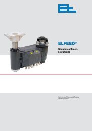
The <strong>ELSTRETCHER</strong> <strong>fabric</strong> <strong>tension</strong> control system is used to control<br />
the clothing in paper or coating machines. It corrects deviations from<br />
a specified <strong>fabric</strong> <strong>tension</strong> set value.<br />
The <strong>fabric</strong> <strong>tension</strong> control system comprises the following components:<br />
- one or two <strong>fabric</strong> <strong>tension</strong> sensors for detecting the <strong>fabric</strong> <strong>tension</strong><br />
actual value (integrated or external <strong>fabric</strong> <strong>tension</strong> sensor)<br />
- <strong>fabric</strong> <strong>tension</strong> controller DC 04../DC 24../DC 90.. with command<br />
station DO 200.<br />
- one actuator (lever arm, chain or spindle type stretcher)<br />
optional<br />
- one position sensor for wrap angle compensation and/or position<br />
monitoring<br />
- one digital interface DI .... (e.g. CAN profibus)<br />
- felt cocking unit VM 1010 for automatic seam correction
Sensor Actuator<br />
External <strong>fabric</strong> <strong>tension</strong> sensor PD 72/73/74<br />
External <strong>fabric</strong> <strong>tension</strong> sensor PD 77<br />
External <strong>fabric</strong> <strong>tension</strong> sensor PD 72/73/74<br />
External <strong>fabric</strong> <strong>tension</strong> sensor PD 77<br />
Integrated <strong>fabric</strong> <strong>tension</strong> sensor EM 10/15<br />
External <strong>fabric</strong> <strong>tension</strong> sensor PD 72/73/74<br />
External <strong>fabric</strong> <strong>tension</strong> sensor PD 77<br />
Design<br />
Integrated <strong>fabric</strong> <strong>tension</strong> sensor EM 08<br />
Optional bearing bracket<br />
Fabric <strong>tension</strong> control system <strong>ELSTRETCHER</strong><br />
Lever arm type stretcher SP 0901, SP 0902<br />
Chain type stretcher SP 1001, SP 1002, SP 1502<br />
Spindle type stretcher SP 0803<br />
Optional position sensor<br />
ANL--250534-EN-05 A page 3
Fabric <strong>tension</strong> control system <strong>ELSTRETCHER</strong><br />
1.3 <strong>Operating</strong> principle<br />
Positioning gear<br />
Fabric <strong>tension</strong> control system with felt<br />
cocking unit VM 1010<br />
1.3.1 Position sensor<br />
(optional)<br />
A page 4 ANL--250534-EN-05<br />
The <strong>fabric</strong> <strong>tension</strong> sensors measure the <strong>fabric</strong> <strong>tension</strong> actual value of<br />
the moving clothing. The <strong>fabric</strong> <strong>tension</strong> may be measured with one or<br />
two electronic <strong>fabric</strong> <strong>tension</strong> sensors (single or two-side measuring).<br />
In the case of two-side measuring the <strong>fabric</strong> <strong>tension</strong> is calculated on<br />
the basis of the signals from both <strong>fabric</strong> <strong>tension</strong> sensors.<br />
In automatic operation the <strong>fabric</strong> <strong>tension</strong> controller continuously compares<br />
the actual <strong>fabric</strong> <strong>tension</strong> with the <strong>fabric</strong> <strong>tension</strong> set value. In<br />
case of variations it forms an actuating signal. The positioning signal<br />
is transmitted to a three-position controller that, in turn, triggers the<br />
drive of the lever arm, chain or spindle type stretcher. Depending on<br />
the polarity of the positioning signal the clothing will be tightened or<br />
slackened.<br />
In <strong>manual</strong> operation the operator can operate the drive for the <strong>tension</strong><br />
using buttons and in this way move the <strong>tension</strong> carriage <strong>manual</strong>ly.<br />
E. g. during a clothing change.<br />
The position sensor is used for position monitoring and/or for wrap<br />
angle compensation.<br />
From the signals from the position sensor, the <strong>fabric</strong> <strong>tension</strong> controller<br />
determines the <strong>tension</strong> carriage position and the correction signal<br />
for the wrap angle compensation.<br />
Position monitoring:<br />
The <strong>tension</strong> carriage position monitoring makes it possible to output<br />
an alarm if thresholds are exceeded in automatic operation. There<br />
are two types of position monitoring, static and dynamic.<br />
In the case of static position monitoring two fixed thresholds are set,<br />
one minimum and one maximum <strong>tension</strong> carriage position. If the<br />
<strong>tension</strong> carriage passes these thresholds in automatic operation, an<br />
alarm is output and the <strong>tension</strong> carriage stopped.<br />
In the case of dynamic position monitoring, a dead zone is set. The<br />
thresholds are calculated from the actual <strong>tension</strong> carriage position<br />
and the dead zone when automatic operation is enabled. If the<br />
<strong>tension</strong> carriage passes these thresholds, an alarm is output and<br />
the <strong>tension</strong> carriage stopped. If the position of the <strong>tension</strong> carriage<br />
changes in automatic operation, the thresholds are continuously adjusted<br />
as per a time set.<br />
Wrap angle compensation:<br />
Wrap angle compensation is a function in the <strong>fabric</strong> <strong>tension</strong> controller.<br />
This function is used to correct changes in the <strong>fabric</strong> <strong>tension</strong> sensor<br />
signal due to changes in the wrapping on the measuring roller.<br />
Important: Pay attention to application notes for dryer groups<br />
in the description "Chain-type stretcher SP 1...", chapter 3.2.
1.3.2 Seam correction<br />
2. Assembly<br />
2.1 Fabric <strong>tension</strong> sensor<br />
2.2 Actuator<br />
2.3 Fabric <strong>tension</strong> controller<br />
2.4 Command stations<br />
(optional)<br />
2.5 Position sensor (optional)<br />
2.6 Digital interface (optional)<br />
2.7 Felt cocking unit (optional)<br />
Fabric <strong>tension</strong> control system <strong>ELSTRETCHER</strong><br />
The stretch roll can be adjusted at one end (tilted) for seam correction.<br />
As standard the chain-type and spindle-type stretchers have a handwheel<br />
for seam correction.<br />
On stretchers equipped with an E+L <strong>tension</strong> controller and the felt<br />
cocking unit VM 1... the adjustment at one end can also be performed<br />
automatically using a motor. The felt cocking process at one<br />
end can be defined individually by entering travel and time. See<br />
separate description.<br />
Please observe the locally applicable and professional safety<br />
and accident prevention regulations.<br />
Fabric <strong>tension</strong> control system assembly may only be performed<br />
by qualified personnel.<br />
The integrated <strong>fabric</strong> <strong>tension</strong> sensors are already mounted on the<br />
actuator.<br />
External <strong>fabric</strong> <strong>tension</strong> sensors, see <strong>fabric</strong> <strong>tension</strong> sensor PD description.<br />
Fit actuator (lever-arm type, chain-type or spindle-type stretcher)<br />
using the description provided. See also dimension drawing and<br />
layout drawing.<br />
Important: Pay attention to application notes for dryer groups<br />
in the description "Chain-type stretcher SP 1...", chapter 3.2.<br />
Fit <strong>fabric</strong> <strong>tension</strong> controller without housing in a control cabinet<br />
supplied by the customer.<br />
Fit <strong>fabric</strong> <strong>tension</strong> controller with operating unit in view of the actuator<br />
if possible.<br />
Fit command stations in view of the actuator if possible.<br />
The position sensor is already fitted to the actuator.<br />
See description for digital interface.<br />
See description for felt cocking unit.<br />
ANL--250534-EN-05 A page 5
Fabric <strong>tension</strong> control system <strong>ELSTRETCHER</strong><br />
3. Installation<br />
3.1 Fabric <strong>tension</strong> sensor<br />
3.2 Actuator<br />
3.3 Fabric <strong>tension</strong> controller<br />
3.4 Command stations<br />
(optional)<br />
3.5 Position sensor (optional)<br />
3.6 Digital interface (optional)<br />
3.7 Felt cocking unit (optional)<br />
A page 6 ANL--250534-EN-05<br />
Please observe the locally applicable and professional safety<br />
and accident prevention regulations.<br />
Fabric <strong>tension</strong> control system installation may only be per-<br />
formed by qualified personnel.<br />
The values specified for the supply voltage in the technical<br />
data chapter must be observed as otherwise operating failures<br />
may occur and the possibility of dangerous situations<br />
arising cannot be excluded.<br />
Connect electrical wires as per the enclosed wiring diagram.<br />
For EMC reasons it is imperative the PE conductor is connected<br />
to all control components.<br />
See description for <strong>fabric</strong> <strong>tension</strong> sensor.<br />
See description for actuator.<br />
See description for <strong>fabric</strong> <strong>tension</strong> controller.<br />
See description for command station/s.<br />
See wiring diagram.<br />
See description for digital interface.<br />
See description for felt cocking unit.
4. Setup-Editor<br />
Command station DO 200.<br />
Fabric <strong>tension</strong> control system <strong>ELSTRETCHER</strong><br />
The <strong>fabric</strong> <strong>tension</strong> control system is operated via the multifunctional<br />
command station DO 200. .<br />
The command station has two operating modes: operating mode for<br />
operating the <strong>fabric</strong> <strong>tension</strong> control system (see chapter Operation)<br />
and setup mode for displaying and editing the parameters in the CAN<br />
network.<br />
While operating mode is designed for the operator on the<br />
machine, settings in setup mode are exclusively reserved for<br />
qualified commissioning and service personnel.<br />
In the "setup editor" chapter basic operation in setup mode is explained.<br />
A detailed description of setup mode, the parameters and<br />
general functions of command station DO 200. may be found in<br />
the description of command station DO 200. .<br />
Amongst others in setup mode:<br />
- the parameters of all CAN devices connected in the CAN network<br />
may be displayed and edited,<br />
- the edited parameter values in the respective CAN devices may<br />
be saved,<br />
- the status of the CAN line checked,<br />
- clearly worded error messages displayed,<br />
- the level of the supply voltage checked,<br />
- service messages displayed,<br />
- the user language set,<br />
- the unit of measurement may be set,<br />
- in the case of multi-operation, customer-specific names may be<br />
set for the individual CAN groups.<br />
A flashing device address means that two CAN devices with the<br />
same CAN address are featured in the CAN network.<br />
If the device designation flashes, the CAN device is not featured (is<br />
not detected by CANMON).<br />
Please note! the setup editor may only be started once, even if<br />
several DO 200. command stations are connected in the CAN network.<br />
ANL--250534-EN-05 A page 7
Fabric <strong>tension</strong> control system <strong>ELSTRETCHER</strong><br />
4.1 Basic operation in setup-mode<br />
A page 8 ANL--250534-EN-05<br />
Start setup mode via the<br />
"Acknowledge" and "Increase value" keys<br />
Select menu item via the<br />
"Increase/decrease value"<br />
keys, e.g. "Show Cannet"<br />
Open/close menu item via the<br />
"Acknowledge" key<br />
Select required device via the<br />
"Increase/decrease value" keys.<br />
Select required<br />
parameter via the<br />
"Increase/decrease<br />
value" keys<br />
Open/close<br />
parameter via the<br />
"Acknowledge" key<br />
The following options are available for quitting setup mode:<br />
1. Go backward step by step, use keys “Acknowledge”, “Value up/dow”<br />
and finally “Escape”.<br />
2. Go backward step by step with the "Escape" key.<br />
3. Leave Setup Mode immediately by pressing one of the following three<br />
keys: "Automatic", “Center”, “Manual”..<br />
If a password is requested in the display,<br />
enter the password via the "Increase/Decrease<br />
value" keys. The cursor may be<br />
moved via key "F 2".<br />
Select the<br />
required parameter<br />
setting via the<br />
"Increase/decrease<br />
value" keys.<br />
Change parameter value via the<br />
"Increase/decrease value" keys<br />
The cursor may be moved with<br />
key "F 2" .<br />
Use the "Acknowledge<br />
" key to set an asterisk,<br />
i.e. adopt the setting.<br />
In the case of rounded<br />
brackets (*) only one<br />
parameter setting may<br />
be selected, in the case<br />
of square brackets [*]<br />
several.
5. Commissioning<br />
5.1 Check actuator assembly<br />
5.2 Check wiring<br />
5.3 Interrupt the power/air<br />
supply<br />
Fabric <strong>tension</strong> control system <strong>ELSTRETCHER</strong><br />
During commissioning or operation no-one may remain in the<br />
danger area around the actuator. Please observe the locally<br />
applicable and professional safety regulations.<br />
Commissioning may only be performed by qualified personnel.<br />
Fabric <strong>tension</strong> controller DC 04../DC 24../DC 90.. does not<br />
have a main switch and once operating voltage is supplied,<br />
is immediately ready for use. It is then in the mode most recently<br />
selected.<br />
The actuator can move immediately in automatic mode!<br />
Commissioning sequence<br />
5.1 Check actuator assembly<br />
5.2 Check wiring<br />
5.3 Interrupt the drive power/air supply.<br />
5.4 Supply power to the <strong>fabric</strong> <strong>tension</strong> control system and set <strong>manual</strong><br />
mode<br />
5.5 Check and set the <strong>fabric</strong> <strong>tension</strong> controller parameters<br />
5.6 Switch on the drive power/air supply.<br />
5.7 Check the actuator direction of travel<br />
5.8 Check the limit position switches<br />
5.9 Place position sensor in operation (optional)<br />
5.10 Check special functions (option)<br />
5.11 Insert clothing<br />
Check actuator assembly.<br />
The actuator must be mounted according to the attached planning<br />
drawing. The actuator must be aligned parallel. The floating bearing<br />
must be mounted in a centred position and move smoothly.<br />
Check the electrical wiring between the <strong>fabric</strong> <strong>tension</strong> sensor, <strong>fabric</strong><br />
<strong>tension</strong> controller and actuator according to the attached wiring<br />
diagram.<br />
Interrupt the drive power/air supply.<br />
Fabric <strong>tension</strong> controller DC 04../DC 24../DC 90.. does not feature<br />
a main switch and is immediately ready for use once the<br />
operating voltage is supplied. It is then in the most recently<br />
selected operating mode.<br />
The actuator can move immediately in automatic mode!<br />
ANL--250534-EN-05 A page 9
Fabric <strong>tension</strong> control system <strong>ELSTRETCHER</strong><br />
5.4 Supply power to <strong>fabric</strong> <strong>tension</strong><br />
control system and<br />
set <strong>manual</strong> mode<br />
5.5 Check and set <strong>fabric</strong> <strong>tension</strong><br />
controller parameters<br />
Set control parameters<br />
P6 - P13<br />
Felt cocking unit<br />
yes<br />
Set parameters for<br />
felt cocking unit<br />
P15 - P23<br />
Set parameters for<br />
<strong>fabric</strong> <strong>tension</strong> sensor/s<br />
P25 - P30<br />
Set parameters for alarms<br />
P32 - P35<br />
External<br />
<strong>fabric</strong> <strong>tension</strong> sensor PD..<br />
yes<br />
Set parameters for<br />
external <strong>fabric</strong> <strong>tension</strong> sensor/s<br />
P40 - P42<br />
Auxiliary modules<br />
yes<br />
Set auxiliary<br />
module addresses<br />
P52 - P55<br />
A page 10 ANL--250534-EN-05<br />
Connect the <strong>fabric</strong> <strong>tension</strong> control system to the operating voltage<br />
and switch on <strong>manual</strong> mode immediately.<br />
no<br />
no<br />
no<br />
Safety switch<br />
on <strong>fabric</strong> <strong>tension</strong><br />
controller<br />
yes<br />
Select safety switch<br />
P57<br />
Wrap angle<br />
compensation<br />
yes<br />
Check and set parameters for wrap<br />
angle compensation P59 - P73<br />
Position monitoring<br />
yes<br />
Set parameters for position<br />
monitoring P59 and P60 ,<br />
check P61 - P73 ,<br />
set P78 - P84<br />
Fabric <strong>tension</strong> set value 2<br />
yes<br />
Set parameters for<br />
<strong>fabric</strong> <strong>tension</strong> set value 2<br />
P75, P76<br />
Terminate parameter<br />
setting<br />
no<br />
no<br />
no<br />
no
5.6 Switch on drive power/air<br />
supply<br />
5.7 Check actuator<br />
direction of travel<br />
5.8 Check limit<br />
switch<br />
Tighten<br />
Slacken<br />
Tighten<br />
Slacken<br />
5.9 Place position sensor<br />
in operation<br />
(optional)<br />
Slacken<br />
5.10 Check special functions<br />
(option)<br />
Fabric <strong>tension</strong> control system <strong>ELSTRETCHER</strong><br />
Start setup mode on command station DO 200. .<br />
Check <strong>fabric</strong> <strong>tension</strong> controller parameters and set the individual<br />
parameter values.<br />
See description "Fabric <strong>tension</strong> controller DC 04../DC 24../<br />
DC 90.." and data sheet with customized settings for wrap angle<br />
compensation. The new parameter values will be immediately adopted<br />
and stored.<br />
Leave Setup Mode.<br />
Switch on the drive power/air supply.<br />
Move the actuator in <strong>manual</strong> mode (tighten and slacken).<br />
If the direction of travel no longer matches the tighten and slacken<br />
function, disconnect the <strong>fabric</strong> <strong>tension</strong> control system from the<br />
power and change the drive direction.<br />
Move the actuator in <strong>manual</strong> mode (tighten and slacken).<br />
With suitable equipment (risk of injury!) actuate the limit posi-<br />
tion switches that are to switch off the actuator drive once the<br />
actuator reaches its limit positions one after the other.<br />
If the effective direction no longer matches the limit position, disconnect<br />
the <strong>fabric</strong> <strong>tension</strong> control system from the power, check<br />
and if necessary change the limit position switch wiring.<br />
Set to <strong>manual</strong>.<br />
Start setup mode on operator panel DO 200. .<br />
Recall parameter 69 (position encoder), then slightly slacken the<br />
actuator. The position sensor must count backwards when slackening.<br />
If this is not the case, recall parameter P3 and start the service<br />
function "toggle encoder dir" (reverse position sensor counting<br />
direction).<br />
While in the <strong>manual</strong> mode slacken the actuator until it reaches the<br />
limit position and the limit switch terminates this process.<br />
Recall parameter P3 and start the service function "store stretcher<br />
0 pos" (save position sensor zero position).<br />
Check customized special functions.<br />
- See description "Fabric <strong>tension</strong> controller DC 04../DC 24../<br />
DC 90..", chapter "Digital inputs/outputs".<br />
- On the usage of addition analog outputs, see description for the<br />
modules AK .... and/or LK ... .<br />
ANL--250534-EN-05 A page 11
Fabric <strong>tension</strong> control system <strong>ELSTRETCHER</strong><br />
5.11 Insert clothing<br />
Slacken<br />
A page 12 ANL--250534-EN-05<br />
Slacken the clothing in the <strong>manual</strong> mode until the actuator reaches<br />
the limit position and the limit switches terminate the process.<br />
Disconnect the <strong>fabric</strong> <strong>tension</strong> control system from the power.<br />
Insert the clothing.<br />
Connect the <strong>fabric</strong> <strong>tension</strong> control system to the power.<br />
Switch on automatic mode.<br />
The clothing is now tightened to the <strong>fabric</strong> <strong>tension</strong> set value.<br />
In the press section pay attention to the change in the length<br />
of the clothing on closing the press. The closing speed must<br />
be adjusted to the actuating speed of the chain-type stretcher.
6. Operation<br />
6.1 Command station DO 200.<br />
6.2 Keys and displays<br />
Group 0<br />
0.0 N/mm<br />
0.0 N/mm<br />
X.4: 0.0 X.5: 0.0<br />
Fabric <strong>tension</strong> control system <strong>ELSTRETCHER</strong><br />
During operation no-one may remain in the danger area<br />
around the actuator. Please observe the locally applicable<br />
and professional safety regulations.<br />
The <strong>fabric</strong> <strong>tension</strong> control system may only be operated by<br />
qualified personnel or suitably instructed persons.<br />
Fabric <strong>tension</strong> controller DC 04../DC 24../DC 90.. does not<br />
have a main switch and once operating voltage is supplied,<br />
is immediately ready for use. It is then in the mode most recently<br />
selected.<br />
The actuator can move immediately in automatic mode!<br />
The <strong>ELSTRETCHER</strong> <strong>fabric</strong> <strong>tension</strong> control system is operated via<br />
command station DO 200. .<br />
In this chapter only the operating functions for the<br />
<strong>ELSTRETCHER</strong> <strong>fabric</strong> <strong>tension</strong> control system are explained.<br />
A detailed description of setup mode, the parameters and<br />
general functions of command station DO 200. may be found<br />
in the command station DO 200. description.<br />
Clearly worded display<br />
Up to eight control systems may be operated via command station<br />
DO 2000.<br />
Line 1 of the clearly worded display indicates for which control<br />
system the command station is currently active, e.g. group 0.<br />
Lines 2, 3 and 4 indicate system-specific values. In the case of a<br />
<strong>fabric</strong> <strong>tension</strong> control system <strong>ELSTRETCHER</strong> these are :<br />
- the belt <strong>tension</strong> target value in line 2<br />
- the belt <strong>tension</strong> actual value in line 3<br />
- the individual actual belt <strong>tension</strong> values of both load sensors in<br />
line 4 (for double-sided measurement only)<br />
The values may be displayed in N/mm or PLi.<br />
ANL--250534-EN-05 A page 13
Fabric <strong>tension</strong> control system <strong>ELSTRETCHER</strong><br />
- (0.E)ZC4070 -<br />
Service<br />
_______________________<br />
OK<br />
Felt cocking : Off<br />
Amplitude : 0 mm<br />
Time : 60 min<br />
Group 0<br />
0.0 N/mm<br />
0.0 N/mm<br />
X.4: 0.0 X.5: 0.0<br />
A page 14 ANL--250534-EN-05<br />
"Help" key<br />
Use the "Help" key to call up the status display. Error messages may<br />
be polled by CAN devices in the status display. Furthermore, E+L<br />
service points with telephone number, fax number and e-mail address<br />
are displayed.<br />
The green display on the "Help" key lights up if all CAN devices are<br />
ok. The yellow display on the key lights up if an error message is<br />
signalled.<br />
Navigation is as follows in the status display:<br />
Key ▲ and ▼: select menu option, e.g. "group 0"<br />
Key ↵: open/close menu options<br />
Key "F 4": terminate status display<br />
Alarm display<br />
The alarm display lights up as soon as a CAN device error message<br />
is supplied (e.g. temperature error, wrong CAN line, alarm period<br />
exceeded etc.. It goes out when the error is cleared.<br />
Device errors may be polled via the "Help" key (see "Help" key).<br />
In the case of serious device errors the <strong>fabric</strong> <strong>tension</strong> control system<br />
is switched off.<br />
Keys F1 and F2 not allocated<br />
F 3 Felt cocking<br />
Use key F 3 to call up the "felt cocking" menu for the optionally available<br />
felt cocking unit. In the "felt cocking" menu the felt cocking unit<br />
may be switched on/off and both the oscillation stroke and time set.<br />
The felt cocking unit only operates if the <strong>fabric</strong> <strong>tension</strong> control system<br />
is set to automatic mode.<br />
Navigation is as follows in the "felt cocking" menu:<br />
Key ↵: select menu options, e.g. "amplitude"<br />
Key F 3: terminate menu<br />
Key ▲and ▼: change values<br />
F 4 Multi-command<br />
Use key F 4 to select the control system for which the command<br />
station is to be active: group 1, group 2, group 3, group 4, group 1<br />
etc. If there is only one control system in the CAN network, key F 4<br />
has no function.<br />
Line 1 of the clear text display shows for which control system the<br />
command station has been activated, for example group 0.
Increase set value<br />
Decrease set value<br />
Tighten<br />
Slacken<br />
Fabric <strong>tension</strong> control system <strong>ELSTRETCHER</strong><br />
"Automatic", "Increase value", "Decrease value" keys<br />
Key "Automatic" starts the automatic mode. The green display of the<br />
key lights up.<br />
In the automatic mode the actuator drive is controlled by the signals<br />
of the belt <strong>tension</strong> controller. If the felt cocking unit is switched on the<br />
felt will be additionally cocked (automatic seam correction).<br />
In automatic mode the <strong>fabric</strong> <strong>tension</strong> set value is changed via the "Increase<br />
value"/"Decrease value" keys. The <strong>fabric</strong> <strong>tension</strong> set value is<br />
changed by one unit (for example 0.1 N/mm) per press of the key.<br />
The <strong>fabric</strong> <strong>tension</strong> set value may however only be changed within<br />
the specified range in parameters 7 and 8. See "Fabric <strong>tension</strong><br />
controller DC 04../DC 24../DC 90.." description. This is designed<br />
to avoid incorrect entries (belt target value too big / too small)<br />
causing actuator or clothing damage.<br />
"Manual mode", "Increase value", "Decrease value" keys<br />
Key "Manual" starts the <strong>manual</strong> mode. The green display of the key<br />
lights up.<br />
In <strong>manual</strong> mode the actuator is moved via the "Increase value/decrease<br />
value" keys (tightened/slackened).<br />
The actuator may only be moved (tightened) until the maximum<br />
set value specified in parameter 7 is reached. See "Fabric <strong>tension</strong><br />
controller DC 04../DC 24../DC 90.." description. This is designed<br />
to avoid incorrect entries causing actuator or clothing damage.<br />
The "Increase value"/"Decrease value" keys are disabled if a<br />
remote control is connected to the <strong>fabric</strong> <strong>tension</strong> controller and<br />
switched on. See "Fabric <strong>tension</strong> controller DC 04../DC 24../<br />
DC 90.." de-scription. In this case the message "disabled" is indicated<br />
in the clearly worded text display. The message must be<br />
deleted via the "Acknowledge" key.<br />
Manual mode is also disabled if the "Disable <strong>manual</strong> mode" input<br />
is activated on the <strong>fabric</strong> <strong>tension</strong> controller.<br />
Keys "Acknowledge", "Escape" and “Center"<br />
have no function.<br />
ANL--250534-EN-05 A page 15
Fabric <strong>tension</strong> control system <strong>ELSTRETCHER</strong><br />
6.3 <strong>Operating</strong> sequence<br />
Group 0<br />
0.0 N/mm<br />
0.0 N/mm<br />
X.4: 0.0 X.5: 0.0<br />
Felt cocking : Off<br />
Amplitude : 0 mm<br />
Time : 60 min<br />
A page 16 ANL--250534-EN-05<br />
No-one is allowed to stay in the hazard area during operation.<br />
Please observe the locally applicable and professional safety<br />
regulations.<br />
The <strong>fabric</strong> <strong>tension</strong> control system may only be operated by<br />
qualified or suitably instructed persons.<br />
Fabric <strong>tension</strong> controller DC 04../DC 24../DC 90.. does not<br />
feature a main switch and once operating voltage is supplied,<br />
is immediately operational. It is then in the most recently selected<br />
operating mode.<br />
The actuator can move immediately in automatic mode!<br />
Enable the <strong>fabric</strong> <strong>tension</strong> control system operating voltage.<br />
Select control system (in the case of multi-commands only).<br />
Select required operating mode.<br />
Switch on the felt cocking unit (only in the case of <strong>fabric</strong> <strong>tension</strong><br />
control systems with felt cocking units).<br />
The felt cocking unit is only active in automatic mode.<br />
If necessary set the amplitude and time.
6.4 Error messages<br />
Error code Error name Description<br />
Fabric <strong>tension</strong> control system <strong>ELSTRETCHER</strong><br />
001 alarm time Max. control time of parameter P38 exceeded<br />
If alarm mode 1 is set in parameter P37, the actuator drive is also stopped.<br />
002 encoder calib Position sensor error:<br />
- Maximum travel parameter P60 exceeded<br />
- Position sensor reference position incorrect or not saved, save reference position in<br />
parameter P3.<br />
- Only one of the position sensor pulse generators is connected, check position sensor.<br />
003 max. diff. lcells Max. permissible difference between the actual values for the <strong>fabric</strong> <strong>tension</strong> from <strong>fabric</strong><br />
<strong>tension</strong> sensor 1 and 2 exceeded, parameter P35<br />
If alarm mode 1 is set in parameter P32, the actuator drive is also stopped.<br />
004 lcell overload Fabric <strong>tension</strong> sensor overloaded (for integrated <strong>fabric</strong> <strong>tension</strong> sensor EM 2000 only)<br />
The actuator drive is stopped.<br />
The drive remains stopped until the error is rectified.<br />
005 hand wheel out Hand wheel disengaged<br />
The actuator drive is stopped.<br />
The drive remains stopped until the handwheel is engaged again.<br />
006 gear blocking Position sensor error (only for wrap angle compensation):<br />
The gearbox self-locking on the actuating device is becoming looser.<br />
The error message appears only in the <strong>fabric</strong> <strong>tension</strong> control mode, parameter P47 = 0<br />
007 reserve -<br />
008<br />
009<br />
switch limit tig.<br />
switch limit s.o.<br />
Limit switch tighten / slacken (1, 2) reached<br />
The actuator drive is stopped.<br />
The drive remains stopped until the actuator has been moved from the end position in<br />
<strong>manual</strong> mode.<br />
010 limit act. value Max. permissible set value error passed, parameter P33/P34<br />
If alarm mode 1 is set in parameter P32, the actuator drive is also stopped.<br />
011<br />
012<br />
AK 4215 n.c. / bad<br />
AK 4014 n.c. / bad<br />
AK 4215 not connected or error in AK 4215<br />
AK 4014 not connected or error in AK 4014<br />
013 motor direction! Direction of rotation incorrect:<br />
- Direction of rotation of the drive on the actuator is incorrect (message appears only in<br />
conjunction with a position sensor), change drive connections.<br />
- Position sensor counting direction incorrect, invert counting direction in parameter P3.<br />
- Direction of rotation of the drive incorrect on the optionally available felt cocking unit,<br />
invert direction of rotation in parameter P3.<br />
If error mode 1 is set in parameter P73, the actuator drive is also stopped.<br />
014 24 V under voltage 19,5 V DC operating voltage not achieved<br />
015 24 V over voltage 30,5 V DC operating voltage exceeded<br />
016 motor thermal fuse Motor protection switch is triggered<br />
The actuator drive is stopped.<br />
The drive remains stopped until the error is rectified.<br />
017 repair switch Customer repair switch on (option)<br />
see description "Logic board LK 4203"<br />
018 position invalid Position sensor error (only for position monitoring):<br />
Alarm limits "min/max position" for the position monitoring passed, parameter P82, P83<br />
If 1 is selected in parameter P84, the actuator drive is also stopped on the occurrence<br />
of this error message.<br />
ANL--250534-EN-05 A page 17
7. Maintenance<br />
7.1 Fabric <strong>tension</strong> sensor<br />
7.2 Actuator<br />
8. Repair<br />
9. Spare parts<br />
10. Technical data<br />
Erhardt + Leimer GmbH<br />
Postfach 10 15 40<br />
D-86136 Augsburg<br />
Telephone (0821) 24 35-0<br />
Fax (0821) 24 35-6 66<br />
Internet http://www.erhardt-leimer.com<br />
E-mail info@erhardt-leimer.com<br />
If one of the errors described in the table occurs, the appropriate<br />
message is indicated in the DO 200. command station display of <strong>fabric</strong><br />
<strong>tension</strong> controller DC 04../DC 24../DC 90.. . The error message is<br />
displayed until the error is cleared.<br />
If several errors are featured simultaneously, the error with the highest<br />
priority is displayed. When this error is no longer featured, the<br />
display changes to the next error code. If no more errors are featured,<br />
the <strong>fabric</strong> <strong>tension</strong> actual and set values are displayed again.<br />
Errors may only be cleared by qualified personnel.<br />
See <strong>fabric</strong> <strong>tension</strong> controller DC 04../DC 24../DC 90.. description.<br />
Maintenance may only be performed by qualified personnel<br />
when the <strong>fabric</strong> <strong>tension</strong> control system and processing<br />
machine are switched off.<br />
See <strong>fabric</strong> <strong>tension</strong> sensor description.<br />
See actuator description.<br />
Necessary repairs on the <strong>fabric</strong> <strong>tension</strong> control system may<br />
only be performed by E+L or a body expressly authorized to<br />
do so.<br />
Spare parts may be supplied on request.<br />
The technical data depend on the respectively implemented devices.<br />
See attached device description.