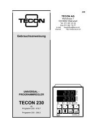
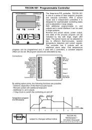
Instruction manual UNIVERSAL-PROGRAMMABLE ... - Tecon AG
Instruction manual UNIVERSAL-PROGRAMMABLE ... - Tecon AG
Instruction manual UNIVERSAL-PROGRAMMABLE ... - Tecon AG

Create successful ePaper yourself
Turn your PDF publications into a flip-book with our unique Google optimized e-Paper software.
<strong>Instruction</strong> <strong>manual</strong><br />
<strong>UNIVERSAL</strong>-<strong>PROGRAMMABLE</strong><br />
CONTROLLER<br />
TECON 202<br />
Programm 202 - 001.9<br />
SET<br />
2 %P<br />
TECON<br />
202<br />
ACT<br />
ALARM<br />
START<br />
STOP<br />
PROG<br />
CONTROLLER
<strong>UNIVERSAL</strong> CONTROLLER TECON 202<br />
Contents :<br />
1. Safety regulations .............................................................................. 4<br />
1.1. Purpose of application of the unit.................................................... 4<br />
1.2. Range of application ....................................................................... 4<br />
1.3. Control range .................................................................................. 4<br />
1.4. Maximum and minimum temperature.............................................. 4<br />
1.5. Operating safety of the control system............................................ 4<br />
1.6. <strong>Instruction</strong>, Manipulations on the unit.............................................. 4<br />
2. Technical data, functions ................................................................... 4<br />
2.1. Overview ......................................................................................... 5<br />
2.2. Method of function .......................................................................... 7<br />
3. Installation.......................................................................................... 8<br />
3.1. Connections .................................................................................... 8<br />
3.2. View of back wall............................................................................. 8<br />
3.3. Dimension sketch............................................................................ 9<br />
3.4. Connection of the sensors .............................................................. 9<br />
3.5. Mounting ......................................................................................... 10<br />
3.6. Dismounting .................................................................................... 10<br />
4. Operation of the controller.................................................................. 11<br />
4.1. Indication and operating elements .................................................. 11<br />
4.2. Setting the nominal value................................................................ 11<br />
4.3. Starting and stopping of the controller............................................. 11<br />
4.4. Alarm............................................................................................... 11<br />
4.5. Starting the program ....................................................................... 12<br />
4.6. Stopping the program...................................................................... 12<br />
4.7. Procedure in case of a power down................................................ 12<br />
4.8. Function check................................................................................ 12<br />
4.9. Control quality ................................................................................. 12<br />
4.10. Indication of software version, alarms and system errors ............. 13<br />
5. Programming the controller................................................................ 14<br />
5.1. Temperature program ..................................................................... 14<br />
5.2. Program sector ............................................................................... 14<br />
5.3. Program run .................................................................................... 14<br />
5.4. Program setting............................................................................... 14<br />
6. Adapting the controller ....................................................................... 16<br />
6.1. Possibilities ..................................................................................... 16<br />
6.2. Adaptation within the protected range............................................. 16<br />
6.3. Alarm data....................................................................................... 18<br />
6.4. Serial interface ................................................................................ 22<br />
6.5. Sensors........................................................................................... 22<br />
6.6. Controller parameters ..................................................................... 25<br />
6.7. System configuration....................................................................... 27<br />
6.8. Analogue inputs and outputs........................................................... 30<br />
6.9. Offsets............................................................................................. 33<br />
Page 2 <strong>Instruction</strong> <strong>manual</strong> TECON <strong>AG</strong>
<strong>UNIVERSAL</strong> CONTROLLER TECON 202<br />
7. Program example .............................................................................. 34<br />
7.1. Needed temperature profile ............................................................ 34<br />
7.2. Program input ................................................................................. 34<br />
8. Serial interface................................................................................... 37<br />
8.1. General ........................................................................................... 37<br />
8.2. Operation with higher ranking control unit:...................................... 37<br />
9. Error messages, faults....................................................................... 39<br />
9.1. Error messages of the controller..................................................... 39<br />
9.2. Faults during operation ................................................................... 39<br />
9.3. Repairs and guarantee ................................................................... 40<br />
10. Designation code ............................................................................. 41<br />
11. List of program data......................................................................... 42<br />
12. List of adjustment data..................................................................... 43<br />
TECON <strong>AG</strong> <strong>Instruction</strong> <strong>manual</strong> Page 3
1. Safety regulations<br />
<strong>UNIVERSAL</strong> CONTROLLER TECON 202<br />
1.1. Purpose of application of the unit<br />
The TECON 202 is designed to control heating and/or cooling systems. The unit is<br />
fitted with a temperature sensor for the control function and if required, a second<br />
sensor can be fitted for monitoring. According to execution of type, the unit can be<br />
fitted with relay contacts or voltage (= signal), or current outputs. Before using the<br />
unit, the type indication should be consulted to see which components are fitted for<br />
the relevant application.<br />
1.2. Range of application<br />
This unit must not be used in explosion hazarded areas. The unit must not be<br />
exposed to rain , nor must it be used in any moist environment<br />
The unit is designed for use at temperatures between 0 and 50°C and a relative<br />
humidity of air of between 10 and 90%. The mains voltage has to correspond with<br />
the type description and may not deviate from this value more than 10%. It is<br />
imperative that the protective earth is (PE) is connected.<br />
Depending on the connected temperature sensor, the unit can control<br />
temperatures up to 1800°C. The user carries all responsibility for any hazards<br />
forthcoming from the generation of high temperatures.<br />
1.3. Control range<br />
The control range has to be adapted. (s. Sensors, on page 15 ff. ). The nominal<br />
value can be adjusted within this range.<br />
1.4. Maximum and minimum temperature<br />
The maximum temperature, above which no more heating is effected, and the<br />
minimum temperature, below which no more cooling is effected, have to be<br />
adjusted (s. Adaptation of alarm data, page 18 ff.).<br />
1.5. Operating safety of the control system<br />
When correctly adjusted and providing the system is operating correctly, the<br />
control range (pt. 1.3) and maximum and minimum temperature (pt. 1.4) avoid<br />
false operations .<br />
In case damage can be caused in the event that the controller does not operate<br />
correctly, it is recommendable to install a safety cut-out<br />
TECON will gladly advise you<br />
1.6. <strong>Instruction</strong>, Manipulations on the unit<br />
It is the responsibility of the user that he understands the operating instructions<br />
and that no manipulations are made on the unit which could affect its safe<br />
functioning. In particular, the unit must not be opened.<br />
2. Technical data, functions<br />
Page 4 <strong>Instruction</strong> <strong>manual</strong> TECON <strong>AG</strong>
2.1. Overview<br />
<strong>UNIVERSAL</strong> CONTROLLER TECON 202<br />
Temperature sensors Thermocouples: Measuring range:<br />
NiCr-Ni (K) -200 to 1200 °C<br />
Fe-Co (J) -200 to 750°C<br />
Pt10Rh-Pt (S) 0 to 1600°C<br />
Pt13Rh-Pt (R) 200 to 1600°C<br />
PtRh18 (B) 200 to 1800°C<br />
Nicrosil-nisil (N)<br />
Resistor:<br />
-200 to 1200°C<br />
Pt 100 -200 to 750°C<br />
Pt 100 with Zener barrier 84 Ohm<br />
Standard signal :<br />
-200 to 400°C<br />
4- 20 mA -200 to 2000°C<br />
0- 20 mA<br />
Temperature<br />
-200 to 2000°C<br />
measurement Accuracy : 0.3% of the range<br />
Resolution : 32000 points<br />
Number of measurements per second 10<br />
Actual-value Indication : 4 digits, LED 14mm height<br />
Resolution: programmable 0.1 °C or 1 °C<br />
Range : according to selected sensor<br />
Nominal value Indication : 4 digits, LED 14mm height<br />
Resolution : programmable 0.1 °C or 1 °C<br />
Range : can be adjusted and limited<br />
Entry : with 2 keys or through external analog signal<br />
or via serial interface<br />
Limit value Following values can be programmed and indicated and<br />
alternatively be sent to an output:<br />
- Maximum temperature<br />
- Minimum temperature<br />
- Deviation from nominal value upward<br />
- Deviation from nominal value downward<br />
- Program - end<br />
- Power down<br />
Control system The control unit contains 2 PID-controllers which can be<br />
programmed for heating or cooling.<br />
Range of the control parameters :<br />
Proportional band 0 to 999 °C<br />
Lead time 0 to 999 s<br />
Lag time 0 to 9999 s<br />
Relay interval time 1 to 999 s<br />
Dead range between heating/cooling 0.1 to 99.9 °C<br />
TECON <strong>AG</strong> <strong>Instruction</strong> <strong>manual</strong> Page 5
<strong>UNIVERSAL</strong> CONTROLLER TECON 202<br />
Outputs 2 controller outputs alternatively:<br />
- Relay contact (normally open contact) 230V , 2A<br />
- signal output for thyristors etc. 24V , 20mA<br />
- continuous current output<br />
1 Limit-value output:<br />
4-20mA or 0-20mA<br />
- relay contact (change-over contact) 230V , 2A<br />
Analogue outputs Sensor temperature, nominal value, control deviation or<br />
control signal (capacity) programmable on 2 outputs<br />
1mV/°C range -0.2 to 2.0 V<br />
10mV/°C range -2.0 to 10.0 V<br />
Voltage programmable 0 to 10 V<br />
Current programmable 4-20mA or 0-20mA<br />
Resolution of the DA-converter 8000 points<br />
Digital input for external controlling of the control unit<br />
programmable<br />
24V, 7mA<br />
Digital output for external linkage of the controller 24V , 20mA<br />
programmable<br />
Serial interface for linking of controllers to master-slave systems<br />
or for connection to other control systems (RS 485) :<br />
- baud rate 9600<br />
- parity odd<br />
- data bits 7<br />
- stop bits 1<br />
- handshake none<br />
Temp. programs 16 program sectors, consisting of 1 ramp, 1 dwell<br />
and 1 dwell time, selectable by key.<br />
temperature<br />
Ramp 0 to 999.9°C/h<br />
Dwell temperature acc. to setpoint range<br />
Dwell time 0 to 9h59min or infinite<br />
Special executions On demand, TECON programs the controller according to<br />
specifications as required by the customer<br />
Mains supply alternately 230/115V , 50/60Hz, 10VA<br />
Ambient temperature 0 to 50°C<br />
Ambient humidity 10 to 90% r.h.<br />
Dimensions Front frame 48 x 96 mm , 5mm high<br />
Controller with case can be exchanged from the front,<br />
can be mounted in any position<br />
mounting depth 125 mm<br />
Weight approx. 0.6 kg<br />
Type of protektion Panel IP 64<br />
Enclosure IP 20<br />
Safety EN 60065<br />
EMC Immunity pr EN 50 082-2<br />
Emission EN 50 081-1<br />
Page 6 <strong>Instruction</strong> <strong>manual</strong> TECON <strong>AG</strong>
2.2. Method of function<br />
<strong>UNIVERSAL</strong> CONTROLLER TECON 202<br />
The TECON 202 controller contains 2 PID controllers which, according to<br />
requirements, can form one controller for heating and one for cooling, 2 controllers<br />
for heating, or 2 controllers for cooling. However, if the controller is used for 2<br />
control systems both systems work with the same nominal value and both are<br />
started and stopped together (2-zone control).<br />
The controller can switch heaters on and off directly via thyristors or relays and can<br />
control the heating capacity by changing the pulse-spacing ratio. But also a servo<br />
motor can be controlled via the two outputs. Continuous final control elements,<br />
such as control valves or phase control systems, can be actuated via the current<br />
outputs or one of the two analogue outputs.<br />
If the controller has to function within a higher ranking system it can be linked in<br />
various manners. The nominal value can be applied as analogue signal. Nominal<br />
value and actual value, the difference between nominal value and actual value and<br />
the correcting variable (capacity) are available in form of analogue values. A digital<br />
input can be used for external controlling and a digital output signals the condition<br />
of the controller. The values of the nominal and actual temperature, the correcting<br />
variable, the controller condition, the alarm data and the control parameters can be<br />
polled and entered via the serial interface.<br />
The range of control can be programmed. A relay contact is available as output for<br />
various monitoring systems. It can be set for a fixed temperature threshold, for a<br />
certain deviation of the temperature from the nominal value, or signalling the end<br />
of the program. Whether the function is to be used as an alarm or merely as a<br />
message to control other devices, can be selected, since the alarm indications can<br />
be suppressed.<br />
16 temperature program sectors each can be feeded in and are called and started<br />
by keystroke.<br />
Example: Program with four sectors<br />
1 2 3 4<br />
time<br />
TECON <strong>AG</strong> <strong>Instruction</strong> <strong>manual</strong> Page 7
3. Installation<br />
<strong>UNIVERSAL</strong> CONTROLLER TECON 202<br />
3.1. Connections<br />
On the back wall of the unit there are 2 rows of plug-in type screw terminals with<br />
15 connections each. The section of the connecting wires is max. 1.5 mm.<br />
3.2. View of back wall<br />
It is essential that the protective earth (PE) is connected.<br />
digital GND<br />
digital output<br />
digital input<br />
analog output 2<br />
analog output 1<br />
analog input<br />
analog GND<br />
current sensor 2 ++<br />
sensor 2 -<br />
sensor 2 +<br />
cold junction<br />
compensation<br />
sensor 1 -<br />
sensor 1 +<br />
current sensor 1 ++<br />
3.2.1. Controller outputs<br />
1<br />
2<br />
3<br />
4<br />
5<br />
6<br />
7<br />
8<br />
9<br />
10<br />
11<br />
12<br />
13<br />
14<br />
15<br />
1 23<br />
1 23<br />
1 2<br />
3<br />
4<br />
1 2<br />
3<br />
4 123<br />
4<br />
J1<br />
Out1<br />
J2<br />
Out2<br />
J3<br />
Sen2<br />
J4<br />
Sen1<br />
J5<br />
A.In<br />
Page 8 <strong>Instruction</strong> <strong>manual</strong> TECON <strong>AG</strong><br />
N<br />
L<br />
PE<br />
-<br />
+<br />
16<br />
17<br />
18<br />
19<br />
20<br />
21<br />
22<br />
23<br />
24<br />
25<br />
26<br />
27<br />
28<br />
29<br />
30<br />
mains<br />
230 / 115 V<br />
50 / 60 Hz<br />
alarm<br />
output 2<br />
output 1<br />
interface<br />
RS 485<br />
Ordering info: 202-XXXX.X-XXX.X output 1 output 2<br />
↓<br />
0<br />
1<br />
2<br />
3<br />
4<br />
5<br />
6<br />
7<br />
8<br />
26<br />
27<br />
26<br />
27<br />
26<br />
27<br />
26<br />
27<br />
26<br />
27<br />
26<br />
27<br />
26<br />
27<br />
26<br />
27<br />
26<br />
27<br />
Relay<br />
23<br />
24<br />
Signal 24V<br />
23<br />
24<br />
Relay<br />
23<br />
24<br />
Signal 24V<br />
23<br />
24<br />
0/4-20mA<br />
Relay<br />
0/4-20mA<br />
23<br />
24<br />
23<br />
24<br />
23<br />
24<br />
23<br />
Signal 24V 24<br />
0/4-20mA<br />
23<br />
24<br />
Relay<br />
Relay<br />
Signal 24V<br />
Signal 24V<br />
Relay<br />
0/4-20mA<br />
0/4-20mA<br />
0/4-20mA<br />
Signal 24V
3.3. Dimension sketch<br />
5<br />
3.4. Connection of the sensors<br />
PT100 4-wires :<br />
PT100<br />
1<br />
PT100<br />
2<br />
<strong>UNIVERSAL</strong> CONTROLLER TECON 202<br />
125<br />
Thermocouples:<br />
PT100 2-wires :<br />
PT100<br />
2<br />
PT100<br />
1<br />
Transmitters :<br />
Transmitter<br />
2<br />
Transmitter<br />
1<br />
TE 2<br />
+<br />
TE 1<br />
+<br />
+<br />
+<br />
removable frame conn.<br />
TECON <strong>AG</strong> <strong>Instruction</strong> <strong>manual</strong> Page 9<br />
1<br />
2<br />
3<br />
4<br />
5<br />
6<br />
7<br />
8<br />
9<br />
10<br />
11<br />
12<br />
13<br />
14<br />
15<br />
1<br />
2<br />
3<br />
4<br />
5<br />
6<br />
7<br />
8<br />
9<br />
10<br />
11<br />
12<br />
13<br />
14<br />
15<br />
1<br />
2<br />
3<br />
4<br />
5<br />
6<br />
7<br />
8<br />
9<br />
10<br />
11<br />
12<br />
13<br />
14<br />
15<br />
1 J1<br />
23<br />
Out1<br />
1 J2<br />
23<br />
Out2<br />
1<br />
2 J3<br />
3 Sen2<br />
4<br />
1<br />
2 J4<br />
3 Sen1<br />
4<br />
1<br />
23 J5<br />
A.In<br />
4<br />
1 J1<br />
23<br />
Out1<br />
1 J2<br />
23<br />
Out2<br />
1<br />
2 J3<br />
3 Sen2<br />
4<br />
1<br />
2 J4<br />
3 Sen1<br />
4<br />
1 23<br />
J5<br />
A.In<br />
4<br />
1 J1<br />
23<br />
Out1<br />
1 J2<br />
23<br />
Out2<br />
1<br />
2 J3<br />
3 Sen2<br />
4<br />
1<br />
2 J4<br />
3 Sen1<br />
4<br />
1<br />
23 J5<br />
A.In<br />
4<br />
96<br />
Jumpersetting for sensors:<br />
Thermocouples:<br />
1<br />
2<br />
3<br />
4<br />
1<br />
2<br />
3<br />
4<br />
1<br />
2<br />
3<br />
4<br />
1<br />
2<br />
3<br />
4<br />
J3<br />
Sen2<br />
J4<br />
Sen1<br />
J3<br />
Sen2<br />
J4<br />
Sen1<br />
SENSOR 2<br />
SENSOR 1<br />
Pt100 2- and 4-wires :<br />
current input:<br />
0-20mA / 4-20mA<br />
1<br />
2<br />
3<br />
4<br />
1<br />
2<br />
3<br />
4<br />
J3<br />
Sen2<br />
J4<br />
Sen1<br />
SENSOR 2<br />
SENSOR 1<br />
SENSOR 2<br />
SENSOR 1<br />
48
3.5. Mounting<br />
<strong>UNIVERSAL</strong> CONTROLLER TECON 202<br />
Cut-out of control panel: : 44 x 92 mm<br />
Thickness of control panel 1 - 4 mm<br />
Insert the two terminal strips through the cut-out of the<br />
panel and plug them in. (The mains input side is coded<br />
and can only be plugged in on that side)<br />
The controller is slid into the cut-out of the panel from the<br />
front and is fixed to the front panel by means of 2 screws.<br />
3.6. Dismounting<br />
Undo the two screws in the front panel so that the<br />
controller can be pulled out from the front. Disconnect the two connector strips.<br />
Page 10 <strong>Instruction</strong> <strong>manual</strong> TECON <strong>AG</strong>
4. Operation of the controller<br />
4.1. Indication and operating elements<br />
SET<br />
2 %P<br />
TECON<br />
ACT<br />
ALARM<br />
START<br />
STOP<br />
PROG<br />
CONTROLLER<br />
4.2. Setting the nominal value<br />
with the keys<br />
<strong>UNIVERSAL</strong> CONTROLLER TECON 202<br />
2 4 digit display<br />
upper display : actual value<br />
lower display : nominal value<br />
(according to selected indication )<br />
7 LED for function control<br />
LED 2 = Data controller 2<br />
LED %P = Capacity<br />
LED ↑ = Output controller 1<br />
LED ALARM = Alarm<br />
LED ↓ = Output controller 2<br />
LED Start/Stop =Controller on/off<br />
LED Prog = cont.: Program running<br />
interim: Programmingmode<br />
4 keys for operation<br />
4.3. Starting and stopping of the controller<br />
Start with key<br />
The LED in the key indicates that the control unit is on<br />
Stop with key<br />
When the control system is switched off the LED is not<br />
lit.<br />
4.4. Alarm<br />
When an alarm is triggered the red LED indicated with<br />
Alarm lights up. At the same time the alarm indication<br />
flashes on the upper display providing the indication<br />
has been programmed with the relevant alarm code<br />
(see page 20). The alarm is acknowledged with the key<br />
TECON <strong>AG</strong> <strong>Instruction</strong> <strong>manual</strong> Page 11
<strong>UNIVERSAL</strong> CONTROLLER TECON 202<br />
4.5. Starting the program<br />
By pressing the key "PROG" one of the set programs<br />
is started ( in the upper indication "Strt" is displayed)<br />
now select with the arrow key the wanted number<br />
of program (displayed in the lower indication).<br />
To acknowledge press the key "START/STOP" .<br />
4.6. Stopping the program<br />
The program can be stopped at any time by pressing the<br />
"START/STOP" key .<br />
To interrupt the running program and later continue use the digital<br />
input (see system data page 28).<br />
4.7. Procedure in case of a power down<br />
After the power has been restored the controller continues running<br />
at the same condition as before the power down event. An alarm is<br />
triggered if such has been configured (alarm code 3). If the alarm<br />
code 3 is set higher than 3, the controller always turns off after a<br />
power down.<br />
4.8. Function check<br />
When the control system is running the LED '###' shows that the<br />
first controller is switched on. The LED '###' shows the condition<br />
of the 2nd controller. The current output can be polled with key<br />
If 2 individual controllers have been programmed their values can<br />
also be polled with key<br />
If a program is running, its conditions are indicated by repeated<br />
pressing of the key<br />
( Displayed is sector number and ramp or remaining time.)<br />
4.9. Control quality<br />
In case the controlling quality is not up to standard it is advisable to<br />
adapt the parameters. To that end see section 6, page 26 ff.<br />
However, the controller can perform this adaptation also of its own<br />
accord if following conditions have been fulfilled:<br />
### No ramp must be run during start-up.<br />
### The difference between starting temperature and the set<br />
nominal value must be 5% or more of the adjusted control range<br />
and higher than 10°C.<br />
### The nominal value must not be altered during the adaptation<br />
process.<br />
### The controller is not operating with external nominal value.<br />
### Adaptation is only possible for the heating parameters, and<br />
only when controller 1 has been configured as heating controller.<br />
When these conditions are fulfilled the controller performs the<br />
adaptation when the 'START/STOP' key is pressed for at least 3<br />
seconds. The adaptation is indicated by the flashing of the LED in<br />
the 'START/STOP' key.<br />
Page 12 <strong>Instruction</strong> <strong>manual</strong> TECON <strong>AG</strong>
<strong>UNIVERSAL</strong> CONTROLLER TECON 202<br />
4.10. Indication of software version, alarms and system errors<br />
On power on, the software version is shown for a few seconds<br />
If an alarm comes up, for which the indication is programmed, it<br />
is shown blinking in the upper display.<br />
(Alarm programming see page 18).<br />
On power on, the device executes several self-tests. An error is<br />
shown in the following way:<br />
The code of the error numbers is given in 'Error messages,<br />
faults' on page 39.<br />
TECON <strong>AG</strong> <strong>Instruction</strong> <strong>manual</strong> Page 13
5. Programming the controller<br />
<strong>UNIVERSAL</strong> CONTROLLER TECON 202<br />
5.1. Temperature program<br />
A temperature program is operating with one or more program sectors. There are<br />
16 possible program sectors.<br />
5.2. Program sector<br />
A program sector includes one dwell temperature, one temperature ramp<br />
programmed in °C per hour, one dwell time programmed in hours and minutes,<br />
and the number of the following sector.<br />
If the ramp is set to zero, the dwell temperature is immediately approached. If the<br />
dwell time is set to --.-- it lasts forever. This means, this sector has to be stopped<br />
<strong>manual</strong>ly. The shortest possible dwell time is 0.<br />
The number of the following sector determines, where the program continues after<br />
ending. Thus every sector between 1 and 16 can be set as next sector. If the own<br />
or a number already being programmed is set, the program will run in a loop until<br />
<strong>manual</strong> stop. With the following sector number = 0, the program ends with this<br />
sector.<br />
5.3. Program run<br />
At start the ramp begins at momentary temperature. The nominal value of the<br />
ramp runs with the indicated gradient until dwell temperature. The program<br />
sequence code defines if dwell time starts immediately at the beginning of the<br />
sector or when the nominal ramp value is equal to the dwell temperature or when<br />
the actual value has reached a certain limit around dwell temperature (see page<br />
27).<br />
5.4. Program setting<br />
If during the program setting more than one minute no key is pushed, the controller<br />
will return to normal operation. By pushing the program key during 3 seconds the<br />
program setting can be stopped at once.<br />
The mode for program setting is shown by the green LED in the "PROG" key<br />
flashing. The values are set by the arrow key.<br />
By short pressing of the "PROG" key, it switches to the next setting value. If this<br />
key is pressed between 1 and 2 seconds, returning to the preceding value is<br />
possible.<br />
Program sectors can not be deleted, they just can be overwritten. For setting,<br />
control, and changes proceed as follows:<br />
Page 14 <strong>Instruction</strong> <strong>manual</strong> TECON <strong>AG</strong>
Step Press key Indication Function<br />
1<br />
2<br />
3<br />
4<br />
5<br />
6<br />
7<br />
8<br />
9<br />
10<br />
11<br />
12<br />
13<br />
during 3sec<br />
<strong>UNIVERSAL</strong> CONTROLLER TECON 202<br />
By entering the code defined by the user (new unit =<br />
0) programming will be enabled. Without valid code<br />
the data can only be checked.<br />
This step is only necessary when data has to be<br />
altered.<br />
The code is acknowledged and if correct, can now be<br />
readjusted. If the code was wrong these two steps are<br />
skipped.<br />
Starting the programming. The number of the sector is<br />
displayed and can be set by the arrow keys.<br />
The nominal value of the program sector is set in °C.<br />
The range can be programmed at system data setting<br />
and sensor choice (see par. 6, page 15 )<br />
The dwell time is set in hours and minutes.<br />
Range: 0 to 99 h 59 min.<br />
--.-- means infinite dwell time.<br />
It is selected by setting the dwell time < 0.<br />
The ramp is set in °C per hour.<br />
Range: 0 to 999.9°C/h. If zero is set the controller<br />
switches directly to the set nominal value .<br />
The following sector is selected. If needed all 16<br />
program sectors can be programmed by repeating<br />
step 6-11. Following sector = 0 terminates the<br />
program. Ending programming by pressing 3 sec. the<br />
"PROG" key.<br />
The programs are stored during 10 years in the controller. Nevertheless it is highly<br />
recommended to record these data. For this purpose see the tables on page 43.<br />
TECON <strong>AG</strong> <strong>Instruction</strong> <strong>manual</strong> Page 15
6. Adapting the controller<br />
6.1. Possibilities<br />
<strong>UNIVERSAL</strong> CONTROLLER TECON 202<br />
The temperature controller can be adapted to the specific case of application within<br />
wide limits. The adaptation takes place within code protected areas for:<br />
- alarm data<br />
- serial interface<br />
- sensors<br />
- control parameters<br />
- system data<br />
- analogue inputs and outputs<br />
- offsets<br />
6.1.1. Alarm data<br />
The conditions under which the alarm relay should switch and when an alarm<br />
indication has to take place can be programmed with alarm codes for the two<br />
sensor inputs and a code for the general alarm routine. Since the alarm indication<br />
and acknowledgement can be switched off, the two different alarm values can also<br />
be used for temperature related switching.<br />
6.1.2. Serial interface<br />
The transmitting data, the device address and an alarm time for stopping the<br />
control in the event of failure of the connection, can be adjusted for linking with<br />
other controllers or with higher ranking systems.<br />
6.1.3. Sensors<br />
The type of sensor used and the nominal-value range can be determined.<br />
6.1.4. Controlling parameters<br />
Here, those values are entered for the two controllers, which are determinative<br />
according to the system to be controlled, such as:<br />
- proportional band<br />
- lead time<br />
- lag time<br />
- relay interval time<br />
- maximum permissible rating<br />
- dead band.<br />
6.1.5 System data<br />
Here, the type of indication, type of program sequence and the digital in- and<br />
outputs are determined.<br />
6.1.6. Analogue inputs and outputs<br />
The available additional analogue input can be configured within wide limits for an<br />
external nominal-value input (see page 30).<br />
The two analogue outputs can be programmed in relation with the value to be<br />
represented, as well as with the range.<br />
6.1.7. Offset<br />
In order to compensate a possible sensor error an offset can be determined for<br />
every input, which corrects the measurement over the entire range by this constant<br />
amount.<br />
6.2. Adaptation within the protected range<br />
Page 16 <strong>Instruction</strong> <strong>manual</strong> TECON <strong>AG</strong>
<strong>UNIVERSAL</strong> CONTROLLER TECON 202<br />
The configuration level can be accessed by simultaneously pressing the "UP" and<br />
the "DOWN" key for 3 seconds.<br />
In order to make changes a code must be known. Without this code the values can<br />
only be checked and not altered. The factory-set code = 0, though, it can be<br />
changed to any figure by the user.<br />
The 7 data ranges are selected by means of the arrow keys (forward or backward)<br />
The operating level can be accessed again at any time by pressing the "PROG"<br />
key during 3 seconds . If no key is pressed for more than 60 seconds the unit<br />
automatically changes back to the operating level.<br />
Pressing the "PROG" key for a short instant switches the display and the entry one<br />
step forward within a data range.<br />
If the "PROG" key is pressed between 1 and 2 seconds the display and the entry<br />
are switched back one step.<br />
6.2.1. Access to configuration<br />
Step Press key Indication Function<br />
1<br />
2<br />
3<br />
4<br />
simultaneous<br />
during 3 sec.<br />
6.2.2. Selection of the data range<br />
By entering the code defined by the user, (with new<br />
unit = 0) programming will be enabled. Without valid<br />
code the data can only be checked.<br />
This step is only necessary when data have to be<br />
altered.<br />
The code is acknowledged and if correct, can now be<br />
readjusted. If the code was wrong these two steps are<br />
skipped.<br />
The code which was reprogrammed at step 3 is now<br />
valid. Now the required data range can be selected.<br />
The data range is selected with the arrow keys (forward and backward)<br />
ALA = alarm data<br />
SER = serial interfaces<br />
SEN = sensors<br />
PAR = control parameter<br />
SYS = system configuration<br />
A.OUT= analogue outputs<br />
OFF = offsets (correction of the actual-value measurement and the external<br />
nominal value)<br />
TECON <strong>AG</strong> <strong>Instruction</strong> <strong>manual</strong> Page 17
<strong>UNIVERSAL</strong> CONTROLLER TECON 202<br />
The "PROG" key gives access to the data of the selected range.<br />
The data are stored in the controller. It is recommendable to record these also in print.<br />
See the list of adjustment data, page 43.<br />
6.3. Alarm data<br />
Step Press key Indication Function<br />
1<br />
2<br />
3<br />
4<br />
5<br />
6<br />
7<br />
8<br />
9<br />
10<br />
11<br />
12<br />
13<br />
Alarm data range.<br />
Adjusting the maximum temperature for sensor 1.<br />
If this temperature is exceeded the heating of<br />
controller 1 is switched off. An alarm is set off only<br />
when this has been programmed.<br />
Range : according to the set sensor.<br />
Adjusting the minimum temperature for sensor 1.<br />
If this temperature falls below the set limit the cooling<br />
of controller 1 is switched off. An alarm is set off only<br />
when this has been programmed.<br />
Range : according to the set sensor.<br />
Adjusting the over temperature limit 1.<br />
If the actual value exceeds the nominal value by this<br />
value an alarm is set off.<br />
Range : 0 - 99°C (over temperature = 0: alarm is<br />
switched off)<br />
Setting the under temperature alarm limit 1.<br />
If the actual value falls below the nominal value by this<br />
amount alarm is set off.<br />
Range : 0 - 99°C (undertemperature = 0: alarm is<br />
switched off)<br />
Setting the alarm code for sensor 1.<br />
For denotation see following table.<br />
Range : 0 - 4<br />
Adjusting the maximum temperature of sensor 2.<br />
When this temperature is exceeded the heating is<br />
switched off. The alarm is set off only when it has<br />
been programmed.<br />
The range depends on the selected sensor.<br />
Page 18 <strong>Instruction</strong> <strong>manual</strong> TECON <strong>AG</strong>
Step Press key Indication Function<br />
14<br />
15<br />
16<br />
17<br />
18<br />
19<br />
20<br />
21<br />
22<br />
23<br />
24<br />
25<br />
26<br />
<strong>UNIVERSAL</strong> CONTROLLER TECON 202<br />
Adjusting the minimum temperature of sensor 2.<br />
When the temperature falls below this value the<br />
cooling is switched off. Alarm is set off only when it<br />
has been programmed. The range depends on the<br />
selected sensor.<br />
Setting the over temperature alarm limit 2.<br />
When the actual value exceeds the nominal value by<br />
this amount alarm is set off.<br />
Range : 0 - 99°C. When 0 is entered the over<br />
temperature alarm 2 is switched off.<br />
Setting the under temperature alarm limit 2.<br />
When the actual value exceeds the nominal value by<br />
this amount alarm is set off.<br />
Range : 0 - 99°C. When 0 is entered the under<br />
temperature alarm 2 is switched off.<br />
Setting the alarm code for sensor 2.<br />
For denotation see following table.<br />
Range : 0 - 4<br />
Setting the alarm code 3.<br />
Range: 0 - 3 , denotation:<br />
Code power on condition program. end<br />
0 no alarm no alarm<br />
1 alarm no alarm<br />
2 no alarm alarm<br />
3 alarm alarm<br />
Setting the threshold temperature (temp. contact).<br />
If sensor 2 has been programmed the threshold<br />
relates to this, otherwise to sensor 1.<br />
Range : according to selected sensor<br />
End of the alarm data range.<br />
A new range can be selected with the arrow keys.<br />
TECON <strong>AG</strong> <strong>Instruction</strong> <strong>manual</strong> Page 19
6.3.1. Alarm code table for Code 1 and 2:<br />
<strong>UNIVERSAL</strong> CONTROLLER TECON 202<br />
Code Function Indication Acknowledge<br />
0 Alarm is switched off none none<br />
1 The alarm relay is open as long as the alarm<br />
conditions are fulfilled.<br />
none none<br />
2 The alarm relay is open as long as the alarm yes only<br />
conditions are fulfilled.<br />
monitoring<br />
3 The alarm relay is released when the alarm yes<br />
condition ensues and remains released until<br />
acknowledged.<br />
yes<br />
4 The alarm relay is released when the alarm yes only<br />
condition ensues. The alarm relay remains released<br />
until the alarm condition vanishes.<br />
monitoring<br />
6.3.2. Alarm types and indications in their sequence of priority<br />
Alarm type Indication Alarm condition<br />
1. Power on P-on power down<br />
2. Sensor break Sensor<br />
symbol<br />
3. Maximum value 1 ∧ °C1<br />
the relevant sensor does not supply a valid<br />
signal<br />
Value sensor 1> programmed alarm value<br />
4. Minimum value _°C1 Value sensor 1< min. alarm<br />
5. Over temperature 1 = °C1 Value sensor 1 exceeds nominal value by more<br />
than the programmed value<br />
6.Undertemperature 1 =<br />
7. Maximum value 2 ∧ °C2<br />
°C1 Value sensor 1 falls below the nominal value by<br />
more than the programmed value<br />
Value sensor 2>programmed alarm value<br />
8. Minimum value 2 _ °C2 Value sensor 2
<strong>UNIVERSAL</strong> CONTROLLER TECON 202<br />
6.3.3. Over- and under temperature alarm<br />
With both the values for over and under temperature limits set, a band around the<br />
setpoint is checked.<br />
If the alarm code is 3 or 4, the controlled value must have been within this band, before<br />
an alarm can come up. If the setpoint is changed, this condition must be fulfilled again.<br />
With alarm code 1 or 2, the alarm occurs always if the controlled value is out of the<br />
checked band.<br />
Examples for Alarm-Code > 2<br />
Mode<br />
1. Over- and under<br />
temperature set<br />
2. Over temperature set<br />
3. Under temperature set<br />
without ramp with ramp<br />
over temp.<br />
Uebertemp.<br />
setpoint<br />
Sollwert<br />
under Untertemp. temp.<br />
Alarm<br />
Uebertemp. Over temp.<br />
Sollwert setpoint<br />
Alarm<br />
setpoint<br />
under<br />
Sollwert<br />
temp.<br />
Untertemp.<br />
Alarm<br />
actual value<br />
Istwert<br />
actual Istwertvalue<br />
TECON <strong>AG</strong> <strong>Instruction</strong> <strong>manual</strong> Page 21<br />
t<br />
t<br />
T<br />
T<br />
actual value<br />
Istwert<br />
Istwert actual value<br />
actual value<br />
T<br />
actual value<br />
Istwert<br />
Istwert<br />
t<br />
t<br />
t<br />
t
6.4. Serial interface<br />
Step Press key Indication Function<br />
1<br />
2<br />
3<br />
4<br />
5<br />
6<br />
7<br />
8<br />
<strong>UNIVERSAL</strong> CONTROLLER TECON 202<br />
Range serial interface<br />
Setting the unit address.<br />
Range: 0 - 31<br />
Setting the code of the 1st serial interface.<br />
For denotation see code table below.<br />
Setting the monitoring time of the 1st interface in<br />
seconds. If no message is identified at the interface<br />
after this interval (e.g. because of wire break) the<br />
control system switches off, the relay falls off and on<br />
the display "Ser.1" flashes.<br />
Range : 0 - 1000 seconds. 0 = monitoring switched off.<br />
End of range serial-interface.<br />
A new range can be selected with the arrow keys.<br />
6.4.1. Code table for the serial interface<br />
Value Adr. Function<br />
0 -- off (no data are received or emitted)<br />
1 99 master, emits nominal value 1 (Adr. 99 for internal use only)<br />
2 -- not used<br />
3 99 slave without reply, regards start/stop, nominal value<br />
4 99 slave without reply, regards start/stop, nom. value = program. nom. value +<br />
master nom. value<br />
5 99 slave without reply, regards start/stop, Progr. nr.<br />
6-15 -- not used<br />
16 0-31 Slave regards all commands and replies, intervention at controller possible<br />
17 0-31 Slave regards all commands and replies, no intervention at controller<br />
possible<br />
If the controller is operated with function code 16 or 17 and in combination with non-<br />
TECON units, we recommend to request the description "Serial standard interface of<br />
the TECON controllers".<br />
6.5. Sensors<br />
Page 22 <strong>Instruction</strong> <strong>manual</strong> TECON <strong>AG</strong>
Step Press key Indication Function<br />
1<br />
2<br />
3<br />
4<br />
5<br />
6<br />
7<br />
8<br />
9<br />
10<br />
11<br />
<strong>UNIVERSAL</strong> CONTROLLER TECON 202<br />
Sensor range<br />
Adjusting the first sensor.<br />
Sensor Range Lower display<br />
----------------------------------------------------------------------<br />
NiCr-Ni (K) -200 - 1200 °C CA<br />
Fe-Co (J) -200 - 750 °C FECo<br />
PtRh10% (S) 0 - 1600 °C PT10<br />
PtRh13% (R) 200 - 1600 °C PT13<br />
Pt100 -200 - 750 °C P100<br />
Pt100 on 84-Ohm -200 - 400 °C P184<br />
Z-Barrier, 2 wires<br />
Pt100 on 84-Ohm -200 - 400 °C P.184<br />
Z-Barrier, 4 wires<br />
4-20 mA -200 - 2000 °C 4-20<br />
0-20 mA -200 - 2000 °C 0-20<br />
PtRh 18% (B) 200 - 1800 °C PT18<br />
Nicrosil-Nisil (N) -200 - 1200 °C NISI<br />
This indication only appears when a current input is<br />
used for sensor.<br />
Adjusting the lower limit of the current input.<br />
Range : -200 to 2000°C<br />
This indication only appears when a current input is<br />
used for sensor.<br />
Adjusting the upper limit of the current input.<br />
Range : -200 to 2000°C<br />
Adjusting the lower limit of the 1st control range. This<br />
control range limits the nominal-value input.<br />
Adjusting the upper limit of the 1st control range.<br />
This control range limits the nominal-value input.<br />
TECON <strong>AG</strong> <strong>Instruction</strong> <strong>manual</strong> Page 23
Step Press key Indication Function<br />
12<br />
13<br />
14<br />
15<br />
16<br />
17<br />
18<br />
19<br />
20<br />
21<br />
22<br />
23<br />
<strong>UNIVERSAL</strong> CONTROLLER TECON 202<br />
Adjustment of the filter constant for sensor 1 ( = max.<br />
temperature change per second ). When value 9.9 is<br />
set a lowpass filter of the 1st order is programmed<br />
with the time constant 8s.<br />
Range : 0.0 - 9.9 °C/sec. (0=filter switched off)<br />
Adjusting the second sensor.<br />
Sensor Range lower indication<br />
---------------------------------------------------------------------<br />
NiCr-Ni (K) -200 - 1200 °C CA<br />
Fe-Co (J) -200 - 750 °C FECo<br />
PtRh10% (S) 0 - 1600 °C PT10<br />
PtRh13% (R) 200 - 1600 °C PT13<br />
Pt100 -200 - 750 °C P100<br />
Pt100 on 84-Ohm -200 - 400 °C P184<br />
Z-Barrier, 2 wires<br />
Pt100 on 84-Ohm -200 - 400 °C P.184<br />
Z-Barrier, 4 wires<br />
4-20 mA -200 - 2000 °C 4-20<br />
0-20 mA -200 - 2000 °C 0-20<br />
PtRh18% (B) 200 - 1800 °C PT18<br />
Nicrosil-Nisil (N) -200 - 1200 °C NISI<br />
This indication appears only when a current input is<br />
used for the sensor.<br />
Setting the lower limit of the current input.<br />
Range : -200 to 2000°C<br />
This indication appears only when a current input is<br />
used for the sensor.<br />
Setting the upper limit of the current input.<br />
Range : -200 to 2000°C<br />
Setting the lower limit of the 2nd control range. This<br />
control range limits the nominal-value input.<br />
The upper limit of the 2nd control range is being set.<br />
This control range limits the nominal-value input.<br />
Page 24 <strong>Instruction</strong> <strong>manual</strong> TECON <strong>AG</strong>
Step Press key Indication Function<br />
24<br />
25<br />
26<br />
6.6. Controller parameters<br />
Step Press key Indication Function<br />
1<br />
2<br />
3<br />
4<br />
5<br />
6<br />
7<br />
8<br />
9<br />
10<br />
11<br />
<strong>UNIVERSAL</strong> CONTROLLER TECON 202<br />
Adjustment of the filter constant for sensor 2 ( = max.<br />
temperature change per second ). When value 9.9 is<br />
set a lowpass filter of the 1st order is programmed<br />
with the time constant 8s.<br />
Range : 0.0 - 9.9 °C/sec. (0=filter switched off)<br />
End of sensor range.<br />
A new range can be selected with the arrow keys.<br />
Parameter range.<br />
Setting the proportional band for controller 1. Within<br />
the proportional band the output is controlled in<br />
proportion to the deviation between nominal and<br />
actual value.<br />
Range : 0 - 999°C (0 = on/off controller)<br />
Setting the lag time 1 (integral). With the lag time the<br />
deviation caused by the proportional control is<br />
compensated.<br />
Range : 0 - 999 seconds<br />
(0=no integral action).<br />
Setting the lead time (differential) 1.<br />
The lead time effects in switching off before the<br />
nominal value is reached, thus avoiding overshoot.<br />
Range : 0 - 999 seconds<br />
(0= no differential action).<br />
Setting the relay interval-time 1. With quasiproportional<br />
control the output with constant interval<br />
time, is effected by changing the pulse-pause ratio.<br />
Range : 1 - 999 seconds.<br />
Setting the maximum output 1 (in %). The output<br />
rating can be limited so as to obtain a smoother<br />
controlling effect.<br />
Range : 10 - 100%<br />
TECON <strong>AG</strong> <strong>Instruction</strong> <strong>manual</strong> Page 25
Step Press key Indication Function<br />
12<br />
13<br />
14<br />
15<br />
16<br />
17<br />
18<br />
19<br />
20<br />
21<br />
22<br />
23<br />
24<br />
25<br />
26<br />
27<br />
28<br />
<strong>UNIVERSAL</strong> CONTROLLER TECON 202<br />
Setting the proportional band for controller 2. Within<br />
the proportional band the output is controlled in<br />
proportion to the deviation between nominal and<br />
actual value.<br />
Range : 0 - 999°C (0 = on/off controller)<br />
Setting the lag time 2 (integral). With the lag time the<br />
deviation caused by the proportional control is<br />
compensated.<br />
Range : 0 - 999 seconds<br />
(0=no integral action)..<br />
Setting the lead time (differential) 2. The lead time<br />
effects in switching off before the nominal value is<br />
reached, thus avoiding overshoot<br />
Range : 0 - 999 seconds<br />
(0= no differential action).<br />
Setting the relay interval-time 2. With quasiproportional<br />
control with constant interval time, the<br />
output is controlled by changing the pulse-pause ratio.<br />
Range : 1 - 999 seconds.<br />
Setting the maximum output 2 (in %). The output<br />
rating can be limited so as to obtain a smoother<br />
controlling effect.<br />
Range : 10 - 100%<br />
Setting the dead band. Within this band, between<br />
heating and cooling, neither heating nor cooling is<br />
active (only with controller Code 0 or 1).<br />
Range : 0 - 99.9°C<br />
Setting the nominal-value offset. With controller Code<br />
6 or 7 the nominal value of the 2nd controller is offset<br />
from the 1st controller by the amount entered here.<br />
Range : -99.9 to 99.9°C.<br />
Setting the adjustment time range for servo motors.<br />
With controllers Code 10 or 11 the response time of<br />
the motor must be entered. This influences the<br />
duration of the control pulses.<br />
Range : 1 - 999 seconds.<br />
End of the parameter range.<br />
A new range can be selected with the arrow keys.<br />
Page 26 <strong>Instruction</strong> <strong>manual</strong> TECON <strong>AG</strong>
<strong>UNIVERSAL</strong> CONTROLLER TECON 202<br />
6.7. System configuration<br />
On this controller the indication, the program mode, the digital in- and outputs and<br />
the type of controller can be adapted to the requirements of the user.<br />
Step Press key Indication Function<br />
1<br />
2<br />
3<br />
4<br />
5<br />
System-data range.<br />
Setting the display code.<br />
Range : 0 - 7<br />
Code Resolution Upper display Lower display<br />
-------------------------------------------------------------------<br />
0 1°C actual value 1 nominal value 1<br />
1 0.1°C actual value 1 nominal value 1<br />
2 1°C actual value 1 actual value 2 (1)<br />
3 0.1°C actual value 1 actual value 2 (1)<br />
4 1°C actual value 2 nominal value 2 (2)<br />
5 0.1°C actual value 2 nominal value 2 (2)<br />
6 1°C no automatic switch-over<br />
7 0.1°C to normal indication.<br />
(1): Indication only when sensor is fitted<br />
(2): Only with controller code 6 or 7<br />
Setting the program sequence code<br />
Code Denotation<br />
----------------------------------------------------------------------<br />
0 Dwell time begins when the setpoint ramp =<br />
setpoint dwell time<br />
1 Dwell time begins when the setpoint ramp =<br />
setpoint dwell time and actual value =<br />
setpoint ±2°C.<br />
2 Dwell time begins when the setpoint ramp =<br />
setpoint dwell time and actual value within<br />
alarm limits dwell time .<br />
3 Dwell time begins with the program sector.<br />
4 The ramp begins at the momentary setpoint.<br />
Dwell time begins when the setpoint ramp =<br />
setpoint dwell time.<br />
5 As code 1 but at ramp = 0 begins dwell time<br />
immediately.<br />
6 As code 2 but at ramp = 0 begins dwell time<br />
immediately.<br />
TECON <strong>AG</strong> <strong>Instruction</strong> <strong>manual</strong> Page 27
Step Press key Indication Function<br />
6<br />
7<br />
8<br />
9<br />
10<br />
11<br />
<strong>UNIVERSAL</strong> CONTROLLER TECON 202<br />
Setting the code for the digital input.<br />
Range : 0 - 5<br />
Code Function<br />
0 Control function off when ext., contact closed.<br />
1 Control function on when ext. contact closed.<br />
Control function off when ext. contact open<br />
2 Control function starts and stops with<br />
ext. pulse.<br />
3 Program starts and switches further with ext.<br />
pulse.<br />
4 Program run interrupts if ext. contact is closed<br />
5 As code 1 but start/stop key is operating.<br />
Setting the code for the digital output.<br />
Range: 0 - 11<br />
Code table Polarity: + -<br />
Impulse at program end 0 1<br />
Impulse at start and stop 2 3<br />
Impulse at sector beginning 4 5<br />
Impulse at beginning dwell time 6 7<br />
Temperature threshold 8 9<br />
controlling on 10 11<br />
Setting the code for the current outputs.<br />
Range: 0 - 7<br />
Code Function<br />
0 0-100% equivalent to 4 - 20 mA<br />
1 0-100% equivalent to 0 - 20 mA<br />
2 -100 -100% equivalent to 4 - 20 mA<br />
3 -100 -100% equivalent to 0 - 20 mA<br />
4 0-100% equivalent to 20 - 4 mA<br />
5 0-100% equivalent to 20 - 0 mA<br />
6 -100 -100% equivalent to 20 - 4 mA<br />
7 -100 -100% equivalent to 20 - 0 mA<br />
Page 28 <strong>Instruction</strong> <strong>manual</strong> TECON <strong>AG</strong>
Step Press key Indication Function<br />
12<br />
13<br />
14<br />
<strong>UNIVERSAL</strong> CONTROLLER TECON 202<br />
Setting the controller code.<br />
Range: 0 - 7<br />
Code Controller 1 Controller 2 Sensor 2<br />
----------------------------------------------------------------<br />
0 heating cooling not fitted<br />
1 heating cooling monitoring<br />
2 heating dig.out not fitted<br />
3 heating dig.out monitoring<br />
4 cooling dig.out not fitted<br />
5 cooling dig.out monitoring<br />
6 heating heating controller 2<br />
7 cooling cooling controller 2<br />
8 2-step controller not fitted<br />
9 2-step controller monitoring<br />
10 motor step contr. not fitted<br />
11 motor step contr. monitoring<br />
Controller code 6 + 7: 2-zone-controller :<br />
2 individual controllers operate with the same nominal<br />
value. With the parameter "Offset nominal value<br />
controller 2" the nominal value of controller 2 can be<br />
offset by a fixed value.<br />
(s. Control parameter step 24 , page 26 )<br />
End of the system range.<br />
A new range can be selected with the arrow keys.<br />
TECON <strong>AG</strong> <strong>Instruction</strong> <strong>manual</strong> Page 29
6.8. Analogue inputs and outputs<br />
Step Press key Indication Function<br />
1<br />
2<br />
3<br />
4<br />
5<br />
6<br />
7<br />
8<br />
9<br />
<strong>UNIVERSAL</strong> CONTROLLER TECON 202<br />
Range analogue inputs and outputs.<br />
Setting of the analogue input.<br />
( External nominal-value input.)<br />
Range: 0 - 5<br />
Code Range<br />
---------------------------------------------------------------------------------------------------------------------------------<br />
0 Nominal value input switched off<br />
1 1 mV/°C<br />
2 10 mV/°C<br />
3 0 - 10 V<br />
4 4 - 20 mA *<br />
5 0 - 20 mA *<br />
* : Connect external shunt resistor 100R<br />
Setting of the lower range limit of the analogue input.<br />
Range: -200 to 2000°C.<br />
This indication appears only when range code 3 - 5<br />
has been selected.<br />
Setting of the upper range limit of the analogue input.<br />
Range: -200 to 2000°C.<br />
This indication appears only when range code 3 - 5<br />
has been selected<br />
Setting of the code for the 1st analogue output.<br />
Range: 0 - 7<br />
Code analogue value<br />
---------------------------------------------------------------------------------------------------------<br />
0 actual value 1<br />
1 actual value 2<br />
2 nominal value 1<br />
3 nominal value 2<br />
4 output 1<br />
5 output 2<br />
6 actual value 1 - nominal value 1<br />
7 actual value 2 - nominal value 2<br />
Page 30 <strong>Instruction</strong> <strong>manual</strong> TECON <strong>AG</strong>
Step Press key Indication Function<br />
10<br />
11<br />
12<br />
13<br />
14<br />
15<br />
16<br />
17<br />
18<br />
19<br />
<strong>UNIVERSAL</strong> CONTROLLER TECON 202<br />
Setting the range of the 1st analogue output.<br />
Code Range Availability<br />
----------------------------------------------------------------------------------------------------------------------------------------------------<br />
0 10mV/°C<br />
1 1 mV/°C 202 -XX0X / XX2X<br />
2 0 - 10V (see page 41)<br />
3 0 - 2 V _________________<br />
4 4 - 20 mA 202 - XX1X / XX3X<br />
5 0 - 20 mA (see page 41)<br />
Setting the lower range limit of the 1st analogue<br />
output.<br />
Range: -200 to 2000°C.<br />
This indication appears only when range code 2 - 5<br />
has been selected. The unit of the output signal Code<br />
4 and 5 is % (-100 to 100).<br />
Setting the upper range limit of the 1st analogue<br />
output.<br />
Range: -200 to 2000°C.<br />
This indication appears only when range code 2 - 5<br />
has been selected. The unit of the output signal Code<br />
4 and 5 is % (-100 to 100).<br />
Setting the code for the 2nd analogue output.<br />
Range: 0 - 7<br />
Code analogue value<br />
----------------------------------------------------------------------------------------------------------------------<br />
0 actual value 1<br />
1 actual value 2<br />
2 nominal value 1<br />
3 nominal value 2<br />
4 output 1<br />
5 output 2<br />
6 actual value 1 - nominal value 1<br />
7 actual value 2 - nominal value 2<br />
Setting the range for the 2nd analogue output.<br />
Code Range Availability<br />
----------------------------------------------------------------------------------------------------------------------------------------------------<br />
0 10mV/°C<br />
1 1 mV/°C 202 -XX0X / XX1X<br />
2 0 - 10V (see page 41)<br />
3 0 - 2 V _________________<br />
4 4 - 20 mA 202 - XX2X / XX3X<br />
5 0 - 20 mA (see page 41)<br />
TECON <strong>AG</strong> <strong>Instruction</strong> <strong>manual</strong> Page 31
Step Press key Indication Function<br />
20<br />
21<br />
22<br />
23<br />
24<br />
<strong>UNIVERSAL</strong> CONTROLLER TECON 202<br />
6.8.1. Jumper settings for analog input and outputs :<br />
analog output 2<br />
analog output 1<br />
analog GND<br />
analog input<br />
analog GND<br />
1<br />
2<br />
3<br />
4<br />
5<br />
6<br />
7<br />
8<br />
9<br />
10<br />
11<br />
12<br />
13<br />
14<br />
15<br />
1<br />
2<br />
3<br />
4<br />
5<br />
6<br />
7<br />
8<br />
9<br />
10<br />
11<br />
12<br />
13<br />
14<br />
15<br />
1 23<br />
1 23<br />
1 2<br />
3<br />
4<br />
1 2<br />
3<br />
4 123<br />
4<br />
1 23<br />
1 23<br />
1 2<br />
3<br />
4<br />
1 2<br />
3<br />
4<br />
1<br />
23<br />
4<br />
Setting the range limit of the 2nd analogue output.<br />
Range : -200 to 2000°C.<br />
This indication appears only when range code<br />
2 - 5 has been selected. The unit of the output signal<br />
Code 4 and 5 is % (-100 to 100).<br />
Setting the upper range limit of the 2nd analogue<br />
output.<br />
Range: -200 to 2000°C.<br />
This indication appears only when range code<br />
2 - 5 has been selected. The unit of the output signal<br />
Code 4 and 5 is % (-100 to 100).<br />
End of the range for analogue inputs and outputs.<br />
A new range can be selected with the arrow keys.<br />
J1<br />
Out1<br />
J2<br />
Out2<br />
J3<br />
Sen2<br />
J4<br />
Sen1<br />
J5<br />
A.In<br />
J1<br />
Out1<br />
J2<br />
Out2<br />
J3<br />
Sen2<br />
J4<br />
Sen1<br />
J5<br />
A.In<br />
an.input<br />
output 1<br />
Jumpersetting for<br />
voltage outputs :<br />
Page 32 <strong>Instruction</strong> <strong>manual</strong> TECON <strong>AG</strong><br />
1<br />
2<br />
3<br />
output 2<br />
1<br />
2<br />
3<br />
J1<br />
Out1<br />
J2<br />
Out2<br />
Jumpersetting for<br />
signal input : current input :<br />
1<br />
2<br />
3<br />
4<br />
J5<br />
A.In<br />
1<br />
2<br />
3<br />
4<br />
J5<br />
A.In<br />
current outputs :<br />
1<br />
2<br />
3<br />
1<br />
2<br />
3<br />
J1<br />
Out1<br />
J2<br />
Out2<br />
voltage input :<br />
1<br />
2<br />
3<br />
4<br />
J5<br />
A.In
6.9. Offsets<br />
Step Press key Indication Function<br />
1<br />
2<br />
3<br />
4<br />
5<br />
6<br />
7<br />
8<br />
<strong>UNIVERSAL</strong> CONTROLLER TECON 202<br />
Offset range.<br />
Setting offset 1.<br />
( Sensor 1)<br />
Range: -99.9 to +99.9°C.<br />
Setting offset 2.<br />
( Sensor 2 )<br />
Range: -99.9 to +99.9°C.<br />
Setting offset 3.<br />
( ext. nominal-value input or analogue input)<br />
Range: -99.9 to +99.9 °C.<br />
End of the offset range.<br />
TECON <strong>AG</strong> <strong>Instruction</strong> <strong>manual</strong> Page 33
7. Program example<br />
7.1. Needed temperature profile<br />
200°C<br />
100°C<br />
<strong>UNIVERSAL</strong> CONTROLLER TECON 202<br />
0h 1h 2h 3h<br />
sector 1: Ramp with 150°C/h at 100°C, holding 30 min.<br />
sector 2: Ramp with 200°C/h at 180°C, holding 1h<br />
sector 3: Ramp with 400°C/h at 50°C, holding 15 min. and turn off<br />
This program must be saved as number 2. The sectors 3-7 must be reserved for other<br />
programs.<br />
7.2. Program input<br />
Step Press key Indication Function<br />
1<br />
2<br />
3<br />
4<br />
simultaneous<br />
during 3sec.<br />
Page 34 <strong>Instruction</strong> <strong>manual</strong> TECON <strong>AG</strong><br />
time<br />
Calling the programming level and input of the code<br />
for the programming (new unit = 0).<br />
Acknowledge the code.<br />
With the arrow keys the sector 2 is selected.
Step Press key Indication Function<br />
5<br />
6<br />
7<br />
8<br />
9<br />
10<br />
11<br />
12<br />
13<br />
14<br />
15<br />
16<br />
17<br />
18<br />
19<br />
20<br />
<strong>UNIVERSAL</strong> CONTROLLER TECON 202<br />
Set the dwell temperature 100°C .<br />
Set the dwell time 30 min.<br />
Set the ramp 150°C/h .<br />
The following sector 8 is set.<br />
Set the dwell temperature 180°C .<br />
Set the dwell time 1h .<br />
Set the ramp 200°C/h .<br />
The following sector 9 is set..<br />
TECON <strong>AG</strong> <strong>Instruction</strong> <strong>manual</strong> Page 35
Step Press key Indication Function<br />
21<br />
22<br />
23<br />
24<br />
25<br />
26<br />
27<br />
28<br />
29<br />
during 3s<br />
<strong>UNIVERSAL</strong> CONTROLLER TECON 202<br />
Set the dwell temperature 50°C.<br />
Set the dwell time 15 min.<br />
Set the ramp 400°C/h .<br />
The following sector 0 is set.<br />
End of programming.<br />
Nominal and actual value is displayed again.<br />
The program can be started only with number 2. If the system is not able to cool and<br />
code 1 or 2 is set as program code (see System configuration page 27) it is possible that<br />
the dwell time of sector 9 is running after a long cooling time or not at all.<br />
Page 36 <strong>Instruction</strong> <strong>manual</strong> TECON <strong>AG</strong>
8. Serial interface<br />
8.1. General<br />
<strong>UNIVERSAL</strong> CONTROLLER TECON 202<br />
The TECON 200 controller series are standard fitted with an RS 485 interface,<br />
which allows the connecting up of several controllers, thus simplifying their<br />
operation. In this case one controller is programmed as master and all the others<br />
as slaves. The connected slaves, according to preselection, do more or less the<br />
same as the master. Thus, only the master has be operated.<br />
The operating performance of the controllers is determined by the code "SER1".<br />
This code is described in Chapter "Adapting the controller" under "serial interface".<br />
One of the connected controllers is made the master by setting its code on 1. This<br />
controller now continually sends its data to all the other connected controllers.<br />
These must have a code set between 3 and 5 so that they do not reply. It is<br />
important that only one controller is emitting as master and all others are receiving,<br />
because otherwise there will be a disarray of emitting units on the common line.<br />
The slaves can be connected to the master in 2 manners:<br />
Code 3 has the effect that the slaves are switched off together with the master,<br />
though do not take over its nominal value, but only its program section. This is of<br />
importance when controllers which do not control the same value, have to operate<br />
together, for instance temperature controllers together with pressure controllers.<br />
Here, the nominal value of the temperature controller does not make sense for the<br />
pressure controller. On the other hand, a temperature program and a pressure<br />
program can run simultaneously.<br />
Neither master nor slaves require an address. Therefore, it irrelevant which value<br />
is shown at the address (Adr.). Internally master and slaves use the address 99 for<br />
their data exchange. However, the alarm time can be used to switch off the slaves<br />
which have no longer a connection with the master in the event of a defect in the<br />
data transfer from the slaves, and to give an alarm message.<br />
8.2. Operation with higher ranking control unit:<br />
If the controller is operated as slave of a higher ranking control system, e.g. a PC,<br />
the code has to be set to 16 or 17 and each unit should have a different address.<br />
This, to make sure that only one controller is polled at a time and that no further<br />
message is given as long as the reply has not be received completely.<br />
Contrary to master-slave operation, always only the addressed controller subjects<br />
to the commands of the master, i.e. every connected controller has to be operated<br />
individually, unless the master uses address 99. This is observed by all connected<br />
controllers also when code 16 or 17 is given.<br />
TECON offers various programs for operation of units with a PC so as to optimise,<br />
document and monitor control systems.<br />
TECON <strong>AG</strong> <strong>Instruction</strong> <strong>manual</strong> Page 37
<strong>UNIVERSAL</strong> CONTROLLER TECON 202<br />
Example: Master-slave operation of 3 controllers.<br />
1<br />
29<br />
30<br />
1<br />
29<br />
30<br />
1<br />
29<br />
30<br />
Master: TECON 230<br />
Data of the serial interface:<br />
Adr.: 0<br />
Ser.1: 1<br />
Alarm: 0<br />
Function:<br />
Only this controller is operated.<br />
Slave 1: TECON 231 heating / cooling<br />
Data of the serial interface:<br />
Adr.: 0<br />
Ser.1: 3<br />
Alarm: 10<br />
Function:<br />
This slave starts and stops with the<br />
master. It controls the same nominal<br />
value. 10 seconds after termination of the<br />
connection with the master it stops.<br />
Slave 2: TECON 202, heating/heating<br />
Data of the serial interface:<br />
Adr.: 0<br />
Ser.1: 5<br />
Alarm: 0<br />
Function:<br />
This slave starts and stops with the<br />
master and it is always in the same<br />
program section as the master. After<br />
disconnection it continues running with<br />
its own program.<br />
Maximum number of controllers 32<br />
Maximum conductor length 1000 m<br />
Conductor cross-section: 0.5 - 1mm²<br />
( long lines to be screened, screen onto PE)<br />
Page 38 <strong>Instruction</strong> <strong>manual</strong> TECON <strong>AG</strong>
9. Error messages, faults<br />
9.1. Error messages of the controller<br />
<strong>UNIVERSAL</strong> CONTROLLER TECON 202<br />
When the controller is switched on it carries out various self-tests. If an error is<br />
found an error message is given.<br />
In the event of errors "SYST" appears on the upper display and the lower display<br />
shows "Err" and a number. The numbers have following denotation:<br />
Indication Cause Remedy<br />
Err1 Data loss Press Start/Stop button. The controller<br />
is initialised. The data entered by the<br />
user are erased and have to be reentered.<br />
Err2 Memory fault int. RAM Switch controller off and on again.<br />
Err3 Fault in the EEPROM Switch controller off and on again.<br />
Err4 Fault in the program memory Switch controller off and on again.<br />
Err5 Fault in the AD-converter Switch controller off and on again.<br />
Err6 Program is not compatible<br />
( Illegal manipulation on the<br />
controller.)<br />
Press the Start/Stop key. The controller<br />
is initialised. The data entered<br />
by the user are erased and have to be<br />
re-entered.<br />
Err7 The controller is not calibrated Press the Start / Stop key. Although<br />
the controller can operate, the inputs<br />
and outputs are no longer sufficiently<br />
accurate.<br />
If the error message appears repeatedly the unit will have to be sent to the<br />
manufacturers for repair.<br />
9.2. Faults during operation<br />
9.2.1. The controller cannot be started.<br />
The controller has been programmed for external start/stop. See Chapter 6.<br />
System data level, digital input or serial interface.<br />
9.2.2. Actual-value indication<br />
Die actual-value indication flashes with the indication of the programmed sensor:<br />
The sensor is not connected correctly, is defective or it does not correspond with<br />
the programmed type.<br />
The actual-value indication is wrong: The connected sensor does not correspond<br />
with the programmed type.<br />
Remedies: Check the sensor. Check the sensor programming. (Sensor level,<br />
sensor type, page 15 ff. )<br />
9.2.3. The nominal value cannot be set<br />
Cause: The control range limits have not be been set correctly ( see page 15 )<br />
Or: The unit is programmed for external nominal value ( See page 30 )<br />
TECON <strong>AG</strong> <strong>Instruction</strong> <strong>manual</strong> Page 39
<strong>UNIVERSAL</strong> CONTROLLER TECON 202<br />
9.2 .4. The control system is not functioning correctly<br />
If the green LED with the arrow pointing upward is lit and the temperature does not<br />
rise, the heating is not connected correctly or it is not powerful enough.<br />
If the green LED with arrow pointing downward is lit and the cooling does not<br />
function, check the cooling system for correct functioning.<br />
If the green LED with the arrow pointing upward does not indicate heating although<br />
the controller is switched on and the nominal value is above the actual value, the<br />
maximum temperature should be checked ( See page 16 ).<br />
The exceeding of the maximum temperature is only indicated when alarm code 1<br />
has been set accordingly ( Level alarm data, alarm code, page 18 ).<br />
If the green LED with the arrow pointing downward does not indicate cooling<br />
although the controller is switched on and the nominal value is below the actual<br />
value, the set minimum temperature should be checked. ( See page 18 ).<br />
The falling short of the minimum temperature is only indicated when alarm code 2<br />
has been set accordingly ( Alarm level, alarm code, page 19 ).<br />
9.2.5. The controller cannot be configured<br />
The code for the entry of the configuring level was wrong. The code can be<br />
entered by the user and thus, also has to be managed by him. On a new unit the<br />
code is 0. The handling of the code is described under Chapter 6, Adaptation. If<br />
the code number has been lost, please contact the manufacturers.<br />
9.3. Repairs and guarantee<br />
If the user cannot eliminate a fault the unit has to be sent to the manufacturers for<br />
repair. The unit must not be opened by the user nor must it be altered in any way.<br />
The manufacturers guarantee faultless operation of the unit during one year after<br />
date of purchase. During this period a defective unit will be repaired at our works in<br />
Oberuzwil or it will be replaced, providing the damage is not caused by<br />
inappropriate use or by unauthorised manipulation. No other claims are<br />
recognised.<br />
Page 40 <strong>Instruction</strong> <strong>manual</strong> TECON <strong>AG</strong>
10. Designation code<br />
T E C O N 2 0 2 X X<br />
No. Input Contr. outputs<br />
1 2<br />
<strong>UNIVERSAL</strong> CONTROLLER TECON 202<br />
X X X X X X Modification<br />
index<br />
Analogue outputs<br />
1 2<br />
Option Program version<br />
0 NiCr-Ni (K) relay relay voltage voltage 001: Standard<br />
1 FeCo (J) signal relay current voltage<br />
2 PtRh10%(S) relay signal voltage current<br />
3 PtRh13%(R) signal signal current current<br />
4 Pt100 current relay<br />
5 Pt100<br />
+ Z-Barr.<br />
relay current<br />
6 4-20mA current current<br />
7 0-20mA signal current<br />
8 NiSil (N) current signal<br />
9 PtRh18%(B)<br />
A acc. to<br />
customer′s<br />
specific.<br />
Ordering specifications Controller outputs:<br />
Standard execution: Normally output 1 is used for<br />
Supply voltage 230V, 50Hz/60Hz heating and output 2 for cooling.<br />
The analogue outputs can be pro-<br />
Special execution grammed for nominal value,<br />
please state in the order: actual value, difference nominal -<br />
actual , or controller capacity<br />
Supply voltage 115V, 50 Hz/60Hz<br />
or 24V, 50Hz/60Hz<br />
Subject to modification without prior notice.<br />
Art.No. <strong>Instruction</strong> <strong>manual</strong> : 096024<br />
TECON <strong>AG</strong> <strong>Instruction</strong> <strong>manual</strong> Page 41
11. List of program data<br />
Code for program data : _______<br />
<strong>UNIVERSAL</strong> CONTROLLER TECON 202<br />
Program sectors<br />
Sector Setpoint dwell time Following sector Remarks<br />
1<br />
2<br />
3<br />
4<br />
5<br />
6<br />
7<br />
8<br />
9<br />
10<br />
11<br />
12<br />
13<br />
14<br />
15<br />
16<br />
Page 42 <strong>Instruction</strong> <strong>manual</strong> TECON <strong>AG</strong>
12. List of adjustment data<br />
Code for adaptation : _______<br />
Alarm data<br />
Maximum temp.1<br />
Minimum temp. 1<br />
Over temp. 1<br />
Under temp. 1<br />
Alarm code 1<br />
Maximum temp. 2<br />
Minimum temp. 2<br />
Over temp. 2<br />
Under temp. 2<br />
Alarm code 2<br />
Alarm code 3<br />
Threshold sensor<br />
Serial interface<br />
Unite Address<br />
Code serial interface<br />
Alarm time serial interface<br />
Sensors<br />
Sensor 1 : Type<br />
Current inp. 1, lower limit<br />
Current inp. 1, upper limit<br />
Nominal value 1, lower limit<br />
Nominal value 1, upper limit<br />
Filter sensor 1<br />
Sensor 2 : Type<br />
Current inp.2, lower limit<br />
Current inp.2, upper limit<br />
Nominal value 2, lower limit<br />
Nominal value 2, upper limit<br />
Filter sensor 2<br />
Offsets<br />
Offset 1 (Sensor 1)<br />
Offset 2 (Sensor 2)<br />
Offset 3 (nominal value)<br />
<strong>UNIVERSAL</strong> CONTROLLER TECON 202<br />
Control parameters<br />
Proportional band 1<br />
Integral time 1<br />
Differential time 1<br />
Relay interval time 1<br />
max. capacity 1<br />
Proportional band 2<br />
Integral time 2<br />
Differential time 2<br />
Relay interval time 2<br />
max. capacity 2<br />
Dead band<br />
Offset nomin. value controller 2<br />
Adjustment time servo motor<br />
System data<br />
Display code<br />
Code for program run<br />
digital input<br />
digital output<br />
I-Code (current output)<br />
R-Code (controlling mode)<br />
Analogue inputs and outputs<br />
Code analogue input (setpoint)<br />
Nominal value input lower limit<br />
Nominal value input upper limit<br />
Code analogue output 1<br />
Analogue output 1 range<br />
Analogue output 1 lower limit<br />
Analogue output 1 upper limit<br />
Code analogue output 2<br />
Analogue output 2 range<br />
Analogue output 2 lower limit<br />
Analogue output 2 upper limit<br />
TECON <strong>AG</strong> <strong>Instruction</strong> <strong>manual</strong> Page 43
<strong>UNIVERSAL</strong> CONTROLLER TECON 202<br />
Page 44 <strong>Instruction</strong> <strong>manual</strong> TECON <strong>AG</strong>