OPGW Installation in Energized Transmission Line - LabPlan
OPGW Installation in Energized Transmission Line - LabPlan
OPGW Installation in Energized Transmission Line - LabPlan

Create successful ePaper yourself
Turn your PDF publications into a flip-book with our unique Google optimized e-Paper software.
Abstract -- Although the <strong>in</strong>stallation of <strong>OPGW</strong> (Optical<br />
Ground Wire) <strong>in</strong> exist<strong>in</strong>g transmission l<strong>in</strong>e has often been carried<br />
out by power transmission companies worldwide, power system<br />
operators has been impos<strong>in</strong>g restrictions to the planned outages<br />
of the transmission l<strong>in</strong>es. Because of this, the Power <strong>Transmission</strong><br />
Companies have opted for the <strong>OPGW</strong> str<strong>in</strong>g<strong>in</strong>g with energized<br />
transmission l<strong>in</strong>es. A quite safe and productive methodology<br />
called “Carrier” was adopted † . The method consists <strong>in</strong> us<strong>in</strong>g a<br />
self-propelled carrier that slides on exist<strong>in</strong>g ground<strong>in</strong>g wire,<br />
while pull<strong>in</strong>g an aramid rope and position<strong>in</strong>g several double<br />
pulleys. The <strong>OPGW</strong> gets strung by pulleys and then replaces the<br />
exist<strong>in</strong>g ground wire. This paper describes the experience of<br />
several <strong>OPGW</strong> str<strong>in</strong>g<strong>in</strong>g, <strong>in</strong>clud<strong>in</strong>g methodology and tools used,<br />
advantages and ma<strong>in</strong> results achieved. Additionally, it shows how<br />
team tra<strong>in</strong><strong>in</strong>g was conducted and security measures undertaken.<br />
Index Terms -- Construction Works for <strong>Transmission</strong> L<strong>in</strong>e;<br />
<strong>Energized</strong> L<strong>in</strong>e; Ground Wires; <strong>OPGW</strong> Cable; <strong>OPGW</strong><br />
<strong>Installation</strong> <strong>in</strong> Alive-L<strong>in</strong>es; Overhead <strong>Transmission</strong> L<strong>in</strong>es.<br />
T<br />
2006 IEEE PES <strong>Transmission</strong> and Distribution Conference and Exposition Lat<strong>in</strong> America, Venezuela<br />
<strong>OPGW</strong> <strong>Installation</strong> <strong>in</strong> <strong>Energized</strong><br />
<strong>Transmission</strong> L<strong>in</strong>e<br />
Fumitaka Nishimura, Member, IEEE, Liliane D. Cicarelli, Member, IEEE, Ruby Rudy Arellano and<br />
Maurício R. Soares, Member, IEEE *<br />
I. INTRODUCTION<br />
he str<strong>in</strong>g<strong>in</strong>g of <strong>OPGW</strong> (Optical Ground Wire) <strong>in</strong> exist<strong>in</strong>g<br />
overhead transmission l<strong>in</strong>es (OHTL) have been often used<br />
<strong>in</strong> many Brazilian power transmission companies. In the<br />
conventional method, the replacement of an exist<strong>in</strong>g ground<br />
wire by <strong>OPGW</strong> required planned outage of the transmission<br />
l<strong>in</strong>e. However, the electric system operator imposes a series of<br />
restrictions to disconnect the transmission l<strong>in</strong>es. For that<br />
reason, transmission companies have opted for <strong>OPGW</strong><br />
<strong>in</strong>stallation <strong>in</strong> energized transmission l<strong>in</strong>es.<br />
In order to avoid disconnect<strong>in</strong>g l<strong>in</strong>es while meet<strong>in</strong>g the<br />
transmission companies´ needed to replace the exist<strong>in</strong>g ground<br />
wire by the <strong>OPGW</strong>, a very safe and productive energized l<strong>in</strong>e<br />
methodology called “Carrier Method” has been apply<strong>in</strong>g † .<br />
The goal of this paper is to describe the experience of<br />
many <strong>OPGW</strong> str<strong>in</strong>g<strong>in</strong>g projects with energized power l<strong>in</strong>es of<br />
different voltage classes (138 kV to 750 kV), performed<br />
dur<strong>in</strong>g the last 6 years. The paper describes the methodology<br />
and characteristics of the l<strong>in</strong>es, tool specification, work teams,<br />
tra<strong>in</strong><strong>in</strong>g, safety practices as well as productivity,<br />
improvements through the method and ma<strong>in</strong> results.<br />
* F. Nishimura (e-mail: fnishimura@procable.com.br).<br />
L. D. Cicarelli (e-mail: lcicarelli@procable.com.br).<br />
R. R. Arellano (e-mail: rubyrudy@procable.com.br).<br />
M. R. Soares (e-mail: mosoares@uol.com.br).<br />
All with PROCABLE Energia e Telecomunicações Ltda.<br />
Avenida Casa Grande, 1960 – Diadema, SP - CEP 09.961-350<br />
BRASIL – Phone: (55)11-4061-9101.<br />
† The “Carrier Method” was developed by Fujikura Ltd, Japanese cable<br />
manufacturer, and with the partnership of Procable Company the methodology<br />
was improved to Brazilian transmission l<strong>in</strong>e characteristics.<br />
1-4244-0288-3/06/$20.00 ©2006 IEEE<br />
II. CARRIER METHOD DESCRIPTION<br />
A. Procedure<br />
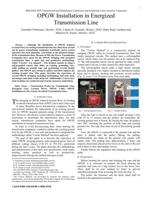
The “Carrier Method” is a construction method for<br />
str<strong>in</strong>g<strong>in</strong>g <strong>OPGW</strong> cables <strong>in</strong> overhead transmission l<strong>in</strong>es with<br />
totally energized circuits. The method uses a self-propelled<br />
carrier, which slides over the ground wire to be replaced (Fig.<br />
1). The self-propelled carrier can be operated by radio remote<br />
control and it can use a video camera for cable <strong>in</strong>spection.<br />
The self-propelled carrier pulls a high tensile strength<br />
specially <strong>in</strong>sulated wire, highly resistant to mechanical impact<br />
loads and to electric track<strong>in</strong>g and positions several pulleys<br />
(Fig. 2), every 15 to 20 meters away from each other.<br />
Fig. 1 - Self-propelled Carrier Fig. 2 – Double Pulleys<br />
Once the rope is tensed <strong>in</strong> one reel length (average 5 km,<br />
with 10 to 15 towers) and the pulleys are positioned, the<br />
exist<strong>in</strong>g ground wire is loosed. By tens<strong>in</strong>g the rope, the pulleys<br />
turn 180º, <strong>in</strong>vert<strong>in</strong>g the position of both rope and exist<strong>in</strong>g<br />
ground wire. The rope then stays on top of the exist<strong>in</strong>g ground<br />
wire.<br />
Next, the <strong>OPGW</strong> is connected to the ground wire and the<br />
latter is pulled with the puller. Dur<strong>in</strong>g the pull<strong>in</strong>g,<br />
re<strong>in</strong>forcements are made on the ground wire repairs with<br />
repairs rods. This pull<strong>in</strong>g lasts approximately 2 hours and<br />
requires electricians placed at the towers at the ends of the reel<br />
and at three or four <strong>in</strong>termediate towers.<br />
F<strong>in</strong>ally follows the regulation and clamp<strong>in</strong>g of the <strong>OPGW</strong><br />
cable.<br />
B. Preparation<br />
Before locat<strong>in</strong>g the carrier and str<strong>in</strong>g<strong>in</strong>g the rope and the<br />
<strong>OPGW</strong>, it is necessary to prepare the local, plac<strong>in</strong>g the<br />
materials and tools on a bag located next to the tower foot.<br />
There shall be an area isolated by fence to prevent<br />
unauthorized people from access<strong>in</strong>g the work site (Fig. 3).<br />
The puller, the tensioner and the drum stand shall be<br />
located <strong>in</strong> the appropriate positions.<br />
1
To have an effective communication system, a radio shall<br />
be placed on the puller, on the tensioner and <strong>in</strong>to the vehicles.<br />
Additionally, portable radios shall be used by the work team<br />
and the l<strong>in</strong>emen who will rema<strong>in</strong> on the towers dur<strong>in</strong>g the<br />
<strong>OPGW</strong> str<strong>in</strong>g<strong>in</strong>g.<br />
Fig. 3 – Puller and Work Site<br />
C. Steps<br />
The <strong>in</strong>stallation method consists of the follow<strong>in</strong>g six steps<br />
[1]:<br />
1) Step 1 – Deploy<strong>in</strong>g the double pulleys<br />
2) Step 2 – Tension<strong>in</strong>g the aramid fiber rope<br />
3) Step 3 – Str<strong>in</strong>g<strong>in</strong>g the <strong>OPGW</strong> cable<br />
4) Step 4 – Tension<strong>in</strong>g the <strong>OPGW</strong> cable<br />
5) Step 5 – Remov<strong>in</strong>g the rope and pulleys<br />
6) Step 6 – Clamp<strong>in</strong>g and Sagg<strong>in</strong>g the <strong>OPGW</strong><br />
D. Advantages<br />
The advantages of this method are:<br />
Low mechanical tension <strong>in</strong> the <strong>OPGW</strong> cable required<br />
dur<strong>in</strong>g the <strong>in</strong>stallation. The typical str<strong>in</strong>g<strong>in</strong>g tension is<br />
300 daN;<br />
M<strong>in</strong>imiz<strong>in</strong>g of <strong>in</strong>stallation sag.<br />
Clearance between ground wire, phase conductors and<br />
<strong>OPGW</strong> can be kept <strong>in</strong> safety distances.<br />
The overload due to the carrier, pulleys, rope and<br />
<strong>OPGW</strong> cable does not affect the exist<strong>in</strong>g ground wire<br />
s<strong>in</strong>ce the load is distributed along the ground wire by<br />
the pulleys.<br />
This method is the safest and most productive,<br />
particularly for EHVTL, for example, 500kV and<br />
750kV.<br />
III. TOOL SPECIFICATIONS<br />
The follow<strong>in</strong>g special tools and equipments are used for<br />
the Carrier Method.<br />
Other types of hardware, used <strong>in</strong> conventional method and<br />
Carrier methods, are not described <strong>in</strong> this paper.<br />
A. Self-propelled Carrier (Fig. 1)<br />
Used for the aramid rope str<strong>in</strong>g<strong>in</strong>g, it runs on a diesel<br />
motor. It weighs from 35 to 40 kg and has a speed of 15 to 30<br />
m/m<strong>in</strong> on the ground<strong>in</strong>g wire. When specified, the selfpropelled<br />
carrier can be remotely controlled via radio and can<br />
also use a video camera to <strong>in</strong>spect the condition of the ground<br />
wire.<br />
B. Aramid Fiber Rope<br />
Essential component of the methodology, the rope must be<br />
<strong>in</strong>sulated, with low humidity absorption, low elasticity<br />
module, high mechanical resistance and high resistance to<br />
electric track<strong>in</strong>g. The rope used is made of aramid coated with<br />
polyethylene, with a nom<strong>in</strong>al diameter of 14mm, weight of<br />
0.160 kg/m and mechanical resistance of 9,000 daN, suit<strong>in</strong>g<br />
works up to 750 kV.<br />
Fig. 4 - Counterweight Tail Device<br />
C. Vertical Double Pulleys (Fig. 2)<br />
The pulley for <strong>OPGW</strong> cable and aramid rope str<strong>in</strong>g<strong>in</strong>g,<br />
<strong>in</strong>stalled along the ground wire, is made of alum<strong>in</strong>um with 2kg<br />
nylon pulley blocks.<br />
D. Curve Pulley Block (Fig. 5 e 6)<br />
Installed on the towers, for 90º angles, its has a steel<br />
articulated framework with 5 or 6 alum<strong>in</strong>um pulley blocks and<br />
weighs 45 kg.<br />
E. S<strong>in</strong>gle Pulley Block (Fig.7)<br />
Installed on the towers, made of alum<strong>in</strong>um alloy, they have<br />
two types: 1,000 mm (40 kg), for structures at the ends of the<br />
reel and 650 mm (23 kg), for structures <strong>in</strong> between them.<br />
Those pulleys are equipped with a slid<strong>in</strong>g device (alum<strong>in</strong>um<br />
pulley block), for the cont<strong>in</strong>ual ground<strong>in</strong>g of the ground wire<br />
(GW) and <strong>OPGW</strong> cables.<br />
F. Counterweight Tail Device (Fig. 4)<br />
A steel counterweight tail flexible device of approximately<br />
1,000 mm to 1,300 mm length (8 to 11 kg); is <strong>in</strong>stalled <strong>in</strong> the<br />
<strong>OPGW</strong>.<br />
G. Antitwist<strong>in</strong>g Wire Rope<br />
An ant twist<strong>in</strong>g wire rope with rated tensile strength of<br />
5.390 daN and weight 0,295 kg/m is used.<br />
H. Puller and Tensioner (Fig. 3, 8 e 9)<br />
Cable tension<strong>in</strong>g, pull<strong>in</strong>g and regulat<strong>in</strong>g equipment<br />
<strong>in</strong>cludes the puller for the cable pull<strong>in</strong>g and the tensioner<br />
which receives the <strong>OPGW</strong> reel, presents the follow<strong>in</strong>g<br />
characteristics:<br />
Tension load: 2,000 daN;<br />
Speed variation: 0 to 4.2 km/h;<br />
Dynamometer and measurer of the cable length;<br />
Two drums with 5 grooves, Ø1,500 mm or Ø660 mm;<br />
Diesel: 24 or 35 HP, air or water cooled;<br />
Weight: 1,700 or 1,400 kg.<br />
2
Note: Despite hav<strong>in</strong>g different functions, the puller and the<br />
tensioner may present the same characteristics.<br />
Fig. 5 - Curve Pulley Block<br />
Fig. 6 - Curve Pulley Block Application Fig. 7 - S<strong>in</strong>gle Pulley Block<br />
Fig. 8 - Puller<br />
Fig. 9 - Tensioner<br />
Ground<strong>in</strong>g<br />
Ground<strong>in</strong>g<br />
IV. WORK TEAM<br />
A. Team Formation<br />
The presence of an experienced electrician is fundamental<br />
<strong>in</strong> the <strong>OPGW</strong> str<strong>in</strong>g<strong>in</strong>g team. This professional must<br />
necessarily have worked with energized circuits of<br />
transmission l<strong>in</strong>es. Aptitudes such as ability, attention and<br />
agility are also paramount: electricians show<strong>in</strong>g a low level of<br />
attention are placed away from risky tasks.<br />
An <strong>OPGW</strong> str<strong>in</strong>g<strong>in</strong>g team comprises at most 60 people<br />
distributed <strong>in</strong>to several crews, as described below. The basic<br />
composition of a team is shown <strong>in</strong> Table I.<br />
1) Str<strong>in</strong>g<strong>in</strong>g crews<br />
Normally, there are three str<strong>in</strong>g<strong>in</strong>g crews, broken <strong>in</strong>to<br />
shifts. The aramid rope str<strong>in</strong>g<strong>in</strong>g is made by the first crew, the<br />
pull<strong>in</strong>g and lay<strong>in</strong>g of <strong>OPGW</strong> is with the second crew and the<br />
third takes away the rope and the pulley blocks, while the first<br />
moves onto the next <strong>OPGW</strong> reel str<strong>in</strong>g<strong>in</strong>g, and so on.<br />
2) Level<strong>in</strong>g and clamp<strong>in</strong>g crew:<br />
In charge of str<strong>in</strong>g<strong>in</strong>g the <strong>OPGW</strong>, dead-end clamp<strong>in</strong>g and<br />
fix<strong>in</strong>g the <strong>OPGW</strong> on the towers.<br />
TABLE I<br />
AVERAGE COMPOSITION OF <strong>OPGW</strong> CREWS (BASIC TEAM WITH 56 PEOPLE)<br />
(1)<br />
Str<strong>in</strong>g<strong>in</strong>g<br />
1 Field Works<br />
person <strong>in</strong><br />
charge<br />
4 Assemblers<br />
3 Assistants<br />
1 Driver<br />
(2)<br />
Level<strong>in</strong>g<br />
1 Field Works<br />
person <strong>in</strong><br />
charge<br />
2 Assembler<br />
2 Levelers<br />
6 Assistants<br />
2 Drivers<br />
CREWS<br />
(3)<br />
Pull<strong>in</strong>g &<br />
Tension<strong>in</strong>g<br />
2 Operators<br />
2 Assistants<br />
1 Derrick<br />
Driver<br />
1 Tractor<br />
driver<br />
(4)<br />
Optical<br />
Splic<strong>in</strong>g<br />
1 Splic<strong>in</strong>g<br />
technician<br />
1 Assistant<br />
3<br />
(5)<br />
Supervision and<br />
Support<br />
1 Supervisor<br />
1 General Field<br />
Works person <strong>in</strong><br />
charge<br />
1 Security<br />
technician<br />
1 Adm<strong>in</strong>istrator<br />
1 Storekeeper<br />
1 Site guard<br />
2 Field guard<br />
Nº OF PEOPLE<br />
3x9 13 6 2 8<br />
3) Team of equipment operators:<br />
Operate the follow<strong>in</strong>g mach<strong>in</strong>es: puller, tensioner, derrick<br />
and tractor to open accesses.<br />
4) Optical Splic<strong>in</strong>g Team:<br />
Makes the splic<strong>in</strong>g of the optical fibers <strong>in</strong> the splic<strong>in</strong>g<br />
boxes of each reel length.<br />
5) Supervision and support team:<br />
Supervisor plans team’s activities and coord<strong>in</strong>ates all<br />
services. The general field works person <strong>in</strong> charge orients and<br />
follows str<strong>in</strong>g<strong>in</strong>g services and the safety technician <strong>in</strong>spects<br />
tasks.<br />
B. Tool Quantity<br />
The quantity of tools and amount of special equipment to<br />
compose an <strong>OPGW</strong> str<strong>in</strong>g<strong>in</strong>g team with energized l<strong>in</strong>e is<br />
presented <strong>in</strong> Table II.
C. Safety<br />
Safety is paramount <strong>in</strong> the Carrier Method and every task<br />
is performed after a thorough risk analysis.<br />
TABLE II<br />
HARDWARE NECESSARY FOR ONE STANDARD TEAM OF <strong>OPGW</strong> STRINGING<br />
Item Tools and Equipment Unit. Qtt.<br />
1 Self-propelled carrier set 3 1<br />
2 Aramid wire rope m 2x6.000<br />
3 Double vertical pulley pc 3<br />
2x250<br />
4 Pulley for angle (banana) pc 2x6<br />
5<br />
S<strong>in</strong>gle pulley block (diameter of 650 and<br />
1,000 mm)<br />
pc 2x(14+4)<br />
6 Antitwist<strong>in</strong>g device pc 2x2<br />
7 Ground wire ant-torsion pilot steel cable m 4x1.000<br />
8 Puller set 1 2<br />
9 Tensioner set 1 2<br />
Notes: 1 – One self-propelled carrier is spare.<br />
2 – When access to tower is difficult, two sets of puller and<br />
tensioner can be used.<br />
3 – pc = piece.<br />
The follow<strong>in</strong>g safety measures are taken:<br />
Ground<strong>in</strong>g of all equipment: o puller and tensioner must<br />
be positioned on a metallic ground<strong>in</strong>g mesh for voltage<br />
equalization.<br />
Ground<strong>in</strong>g are made <strong>in</strong> the exist<strong>in</strong>g ground wire and<br />
<strong>OPGW</strong> us<strong>in</strong>g slid<strong>in</strong>g devices <strong>in</strong>stalled <strong>in</strong> the s<strong>in</strong>gle<br />
pulley block (Figure 7), tensioner (Figure 9) and puller.<br />
Utilization of proven quality tools. No imitations or<br />
experimental tool<strong>in</strong>g is allowed.<br />
A factor greatly h<strong>in</strong>der<strong>in</strong>g security is ra<strong>in</strong>. No str<strong>in</strong>g<strong>in</strong>g<br />
takes place when the ra<strong>in</strong> is light, or when relative humidity of<br />
the air is too high.<br />
Individual protection equipment deserves special attention.<br />
Basically, the follow<strong>in</strong>g type of equipment is used: <strong>in</strong>sulated<br />
gloves, <strong>in</strong>sulated sleeves, helmets and goggles. Conductive<br />
clothes and boots are worn <strong>in</strong> structure with high<br />
electromagnetic <strong>in</strong>duction, particularly at 440, 500 and 750 kV<br />
[1].<br />
Another important security measure regards the<br />
compliance with regulat<strong>in</strong>g standards of medic<strong>in</strong>e and labor<br />
security, usually issued by the M<strong>in</strong>istries of Labor. They are<br />
followed strictly and usually encompass:<br />
1) Standards for previous <strong>in</strong>spection and service orders;<br />
2) Standard for it<strong>in</strong>erary and programm<strong>in</strong>g of the region’s<br />
exist<strong>in</strong>g human resources, such as: hospitals, fire departments,<br />
police departments and forestall services<br />
3) Standard for the constitution and regulation of <strong>in</strong>ternal<br />
commissions for accident prevention;<br />
4) Standard for <strong>in</strong>dividual protection equipment;<br />
5) Standard for medical exam<strong>in</strong>ations;<br />
6) Standard for environmental risks;<br />
7) Standard for electricity services;<br />
8) Standard for cargo transportation and shift<strong>in</strong>g.<br />
It shall be emphasized that the work of <strong>OPGW</strong> str<strong>in</strong>g<strong>in</strong>g is<br />
only <strong>in</strong>itiated after the evaluation of the local conditions and<br />
the complexity of the services.<br />
D. Tra<strong>in</strong><strong>in</strong>g<br />
Tra<strong>in</strong><strong>in</strong>g is one of the ma<strong>in</strong> parts of the Carrier Method.<br />
All members of the team that <strong>in</strong>stalled the <strong>OPGW</strong> participate<br />
<strong>in</strong> previous tra<strong>in</strong><strong>in</strong>g to the Carrier Method.<br />
From time to time recycl<strong>in</strong>g takes place. Additionally,<br />
technical audit<strong>in</strong>g by <strong>in</strong>dependent experts occurs dur<strong>in</strong>g task<br />
performances to assess <strong>in</strong>curred vices and risks.<br />
Tra<strong>in</strong><strong>in</strong>g is established <strong>in</strong> two phases:<br />
1) Theoretical tra<strong>in</strong><strong>in</strong>g<br />
First aid, task sequence, procedures regard<strong>in</strong>g climb<strong>in</strong>g<br />
towers and mov<strong>in</strong>g about towers, methodologies to draw up<br />
materials, mak<strong>in</strong>g of knots <strong>in</strong> ropes, height tasks, security<br />
distances, draw<strong>in</strong>g and mach<strong>in</strong>e speed.<br />
2) Practical tra<strong>in</strong><strong>in</strong>g<br />
Methodology simulation us<strong>in</strong>g de-energized l<strong>in</strong>es and real<br />
application (energized l<strong>in</strong>e), <strong>in</strong> low speed.<br />
One of the greatest concerns of the method regards human<br />
safety so the tra<strong>in</strong><strong>in</strong>g emphasizes this aspect on a constant<br />
basis. One of the most important po<strong>in</strong>ts discussed <strong>in</strong> the<br />
method is tower climb<strong>in</strong>g, due to <strong>in</strong>duced voltage, particularly<br />
<strong>in</strong> 345 kV and above. Climb<strong>in</strong>g takes place <strong>in</strong> pre-determ<strong>in</strong>ed<br />
locations <strong>in</strong> the tower. It is worth highlight<strong>in</strong>g that 80% of the<br />
services are conducted at the top of the towers, where<br />
conductors are energized.<br />
The method does not admit tools fall<strong>in</strong>g from the top of the<br />
towers.<br />
Another crucial factor concerns the <strong>in</strong>tegration with the<br />
methods and practices of the clients. Only after a previous<br />
assessment has been made of regional characteristics, access<br />
maps, types of towers and their mechanical load<strong>in</strong>g can the<br />
methodology be adapted to each case and type of l<strong>in</strong>e.<br />
V. INSTALLATIONS<br />
A. <strong>Transmission</strong> L<strong>in</strong>es<br />
Between 2001 and 2006, was <strong>in</strong>stalled <strong>in</strong> Brazil 4,998 km<br />
of <strong>OPGW</strong> us<strong>in</strong>g the Carrier Method <strong>in</strong> energized OHTL, <strong>in</strong><br />
voltages from 69 kV to 500 kV [2].<br />
Over these six years, approximately 1,050 coils were<br />
launched.<br />
Table III briefly lists clients and <strong>OPGW</strong> cables <strong>in</strong>stalled.<br />
The table enclosed presents more details regard<strong>in</strong>g cast<strong>in</strong>gs,<br />
<strong>in</strong>clud<strong>in</strong>g one for an ADSS cable and another for the<br />
replacement of GW, at 750 kV.<br />
Dur<strong>in</strong>g several str<strong>in</strong>g<strong>in</strong>g, services <strong>in</strong>cluded the <strong>in</strong>stallation<br />
design, the supply of the <strong>OPGW</strong> and its <strong>in</strong>stallation.<br />
Figures 10 to 14 show a few OHTL where <strong>OPGW</strong> cables<br />
were str<strong>in</strong>g<strong>in</strong>g through the Carrier Method. The diversity <strong>in</strong><br />
the OHTL l<strong>in</strong>es can be verifies, as well as the numerous<br />
models of structures (delta, racket and pyramid).<br />
4
Year<br />
2001<br />
2002<br />
2003<br />
2002<br />
2003<br />
2004<br />
2005<br />
TABLE III<br />
INSTALLATION OF <strong>OPGW</strong> WITH ENERGIZED LINES<br />
(TOTAL OF 4,998 KM AND 1,049 REELS)<br />
<strong>Transmission</strong><br />
Company<br />
CHESF<br />
OHTL<br />
Voltage<br />
230 kV<br />
500 kV<br />
Quantity<br />
km<br />
319<br />
CEEE 230 kV 283<br />
<strong>OPGW</strong><br />
Fiber No.<br />
24<br />
36<br />
24<br />
36<br />
2003 COPEL 230 kV 34 36<br />
2004<br />
2005<br />
ELETRONORTE<br />
230 kV<br />
500 kV<br />
1.264<br />
36<br />
72<br />
2004<br />
2005<br />
2006<br />
FURNAS<br />
230 kV<br />
345 kV<br />
138 kV<br />
321<br />
12<br />
24<br />
2004<br />
2005<br />
CTEEP<br />
230 kV<br />
345 kV<br />
440 kV<br />
69 kV<br />
729 12<br />
2006 EMBRATEL 230 kV<br />
345 kV<br />
2.048 24<br />
Fig. 10 - CHESF’s 500 kV OHTL, Paulo Afonso - X<strong>in</strong>gó (2001)<br />
Fig. 11 - ELETRONORTE’s 230 kV OHTL, V. Conde-Sta. Maria (2004)<br />
Fig. 12 - ELETRONORTE’s 500 kV OHTL, Tucuruí-V.Conde (2004)<br />
Fig. 13 – ELETRONORTE’s OHTL 500 kV, Imperatriz-Tucuruí (2004)<br />
Fig. 14 - CTEEP’s 440 kV OHTL, Bauru-Embu (2005)<br />
5
B. <strong>OPGW</strong> Characteristics<br />
The ma<strong>in</strong> characteristics of <strong>OPGW</strong> <strong>in</strong>stalled are: [2]:<br />
Sectional area: from 105 to 150 mm 2 ;<br />
<strong>OPGW</strong> cable diameter: from 13.8 to 16.3 mm;<br />
Tensile strength: from 9,209 to 12,900 kgf; and<br />
Weight: from 623 to 896kgf/km.<br />
The <strong>OPGW</strong> recommended for <strong>in</strong>stallation <strong>in</strong> energized<br />
transmission l<strong>in</strong>es us<strong>in</strong>g the Carrier Method is the double layer<br />
cable (Figure 15) because it is not necessary to use a ant<br />
twist<strong>in</strong>g device dur<strong>in</strong>g <strong>in</strong>stallation works, keep<strong>in</strong>g the orig<strong>in</strong>al<br />
distance between the ground wire and the phases conductors.<br />
The ant twist<strong>in</strong>g device has a length of approximately 1.30m,<br />
which limits the work<strong>in</strong>g distance between the ground wire<br />
and the phase cables.<br />
C. OHTL Particularities<br />
The str<strong>in</strong>g<strong>in</strong>g of <strong>OPGW</strong> cable with energized l<strong>in</strong>es can be<br />
made at any voltage or type tower.<br />
Anticorrosive grease<br />
Steel-Al. Wire<br />
3,30mm<br />
Al.-Alloy Wire<br />
2,55mm<br />
Optical Unit<br />
2,55mm<br />
(Inox Tube)<br />
Fig. 15 - Double Layer <strong>OPGW</strong> from Fujikura, 12 OF, 115 mm2 (CTEEP)<br />
The ma<strong>in</strong> metallic structures of OHTL where <strong>OPGW</strong> were<br />
<strong>in</strong>stalled and their ma<strong>in</strong>ly characteristics are:<br />
1) Delta tower (structure)<br />
For examples: OHTL’s 500 kV Paulo Afonso – X<strong>in</strong>go<br />
(CHESF company) with 55km <strong>OPGW</strong> length (Figure 10),<br />
Tucuruí - Vila do Conde, ELETRONORTE with 273 km<br />
<strong>OPGW</strong> length (Figure 12), and some transmission l<strong>in</strong>es 440kV<br />
of CTEEP company, likes Bauru - Embu Guaçu, with 85 km<br />
<strong>OPGW</strong> length.<br />
2) Racquet tower<br />
Example: OHTL’s 500 kV Imperatriz - Tucuruí, from<br />
ELETRONORTE company, with 413 km <strong>OPGW</strong> length. This<br />
type of structure did not require the replacement of the ground<br />
wire, but rather the <strong>in</strong>stallation of <strong>OPGW</strong> at the side of the<br />
structure, as seen <strong>in</strong> Figure 13 (left side), with energized<br />
phases.<br />
3) Pyramid Tower – double circuit<br />
One such example is OHTL’s 230 kV Vila do Conde - Sta<br />
Maria, from ELETRONORTE, 167 km length (Figure 16).<br />
The replacement of the GW by the <strong>OPGW</strong> was very careful<br />
because the cable stayed on the phases and on the same<br />
alignment. The Carrier Method has the advantage of the least<br />
“clearance” between cables.<br />
Fig. 16 - ELETRONORTE’s 230 kV OHTL, V. Conde-Sta. Maria (2004)<br />
Another example of pyramid tower is the TL 440 kV<br />
Cabreuva - Embu, from CTEEP Company, 77 km length<br />
(Figure 14). Because CTEEP’s 440 kV towers have a different<br />
design configuration than the others, some precautions were<br />
deemed necessary to avoid mechanical damage to the angle<br />
brackets of the tower (extension <strong>in</strong> the structure for fix<strong>in</strong>g the<br />
ground wire).<br />
VI. PRODUCTIVITY<br />
Conductors Clearance, tower types, l<strong>in</strong>es angles, physical<br />
state of the metallic structures and ground wire, soil<br />
topography, accesses ways, communication system, tra<strong>in</strong><strong>in</strong>g,<br />
electricians experience and ma<strong>in</strong>ly the adopted method are<br />
factors <strong>in</strong>fluenc<strong>in</strong>g the productivity of <strong>OPGW</strong> str<strong>in</strong>g<strong>in</strong>g.<br />
A previous analysis of the l<strong>in</strong>e precedes the <strong>OPGW</strong><br />
str<strong>in</strong>g<strong>in</strong>g plann<strong>in</strong>g, <strong>in</strong> which the factors <strong>in</strong>fluenc<strong>in</strong>g<br />
productivity are observed.<br />
The average productivity achieved <strong>in</strong> <strong>OPGW</strong> str<strong>in</strong>g<strong>in</strong>g<br />
through traditional methods with de-energized l<strong>in</strong>es is 60 to 70<br />
km/month. Early methods developed for <strong>OPGW</strong> str<strong>in</strong>g<strong>in</strong>g with<br />
energized l<strong>in</strong>es presented a productivity of 25 to 30 km/month.<br />
Follow<strong>in</strong>g a long experience, described <strong>in</strong> the abovementioned<br />
item IV, the average productivity that has been<br />
achieved through the Carrier Method is 60 km/month/shift or<br />
the str<strong>in</strong>g<strong>in</strong>g of reels of app. 5 km, per week. This productivity<br />
is achieved with a standard team of around 60 people. In the<br />
presence of favorable factors, a total of 5 reels are str<strong>in</strong>g<strong>in</strong>g<br />
per week, as was the case <strong>in</strong> parts of OHTL of<br />
ELETRONORTE Company.<br />
VII. CONCLUSIONS<br />
The "Carrier Method” has been used for more than 12<br />
years <strong>in</strong> many countries all the world. It was developed for<br />
Brazilian overhead transmission l<strong>in</strong>es and demonstrated total<br />
safety <strong>in</strong> the <strong>OPGW</strong> <strong>in</strong>stallations on energized l<strong>in</strong>es.<br />
In Brazil, it has already str<strong>in</strong>ged approximately 5,000 km<br />
of <strong>OPGW</strong>, with energized l<strong>in</strong>es, <strong>in</strong> the period of 2001/2006, <strong>in</strong><br />
l<strong>in</strong>es rang<strong>in</strong>g from 69 kV to 500 kV, with no accidents, as<br />
verified <strong>in</strong> the str<strong>in</strong>g<strong>in</strong>g work.<br />
The average productivity atta<strong>in</strong>ed <strong>in</strong> the str<strong>in</strong>g<strong>in</strong>g was 60<br />
km/month/shift (average 3 reels per work<strong>in</strong>g week), with a<br />
team of approximately 60 people. This productivity is<br />
practically the same as that obta<strong>in</strong>ed through conventional<br />
methods <strong>in</strong> de-energized l<strong>in</strong>es.<br />
6
The successful experience <strong>in</strong> the six last years us<strong>in</strong>g the<br />
“Carrier Method” <strong>in</strong> Brazil makes it a valuable tool to be used<br />
<strong>in</strong> any country, particularly <strong>in</strong> Lat<strong>in</strong> America, whose electrical<br />
system resembles the Brazilian.<br />
The Carrier Method can also be used for <strong>in</strong>spect<strong>in</strong>g the<br />
GW of OHTL, for replacement or ma<strong>in</strong>tenance of damaged<br />
parts of cable. That was done <strong>in</strong> a 750 kV l<strong>in</strong>e <strong>in</strong> FURNAS<br />
(see enclosed Table 4).<br />
The practice and experience acquired <strong>in</strong> numerous<br />
str<strong>in</strong>g<strong>in</strong>g services allowed verify<strong>in</strong>g that productivity varies<br />
not only accord<strong>in</strong>g to type of tower, voltage, transmission l<strong>in</strong>e<br />
length, conditions of structure load<strong>in</strong>g and distance from<br />
ground wire to phase conductor, but also accord<strong>in</strong>g to the type<br />
of region (access, topography, geographic accidents). Those<br />
factors are taken <strong>in</strong>to consideration when def<strong>in</strong><strong>in</strong>g the costs of<br />
services, which vary accord<strong>in</strong>g to type of tower and l<strong>in</strong>e<br />
voltage.<br />
Nowadays, the “Carrier” is deemed as a proven and widely<br />
accepted method by the <strong>Transmission</strong> Companies.<br />
VIII. REFERENCES<br />
Papers from Conference Proceed<strong>in</strong>gs:<br />
[1] “Technology and Construction Works for <strong>OPGW</strong> <strong>Installation</strong> <strong>in</strong> Alive-<br />
L<strong>in</strong>e <strong>Transmission</strong> L<strong>in</strong>e”, IEEE’03 T&D Conference and Exposition,<br />
Dallas, USA, Sep.2003.<br />
[2] “Lançamentos de <strong>OPGW</strong> com Circuitos Energizados em L<strong>in</strong>has de<br />
Transmissão – Metodologia Consagrada”, SNPTEE – Curitiba - PR,<br />
BRASIL, Out.2005.<br />
IX. BIOGRAPHIES<br />
Fumitaka Nishimura is a member of IEEE. He received his BSEE, <strong>in</strong> 1973<br />
and the MSEE, <strong>in</strong> 1977 from USP - São Paulo University, Brazil. He obta<strong>in</strong>ed<br />
his doctor degree <strong>in</strong> 1988, <strong>in</strong> Power System, from USP. He was teacher at<br />
USP from 1976 up to 2003. He worked for Pirelli, Alcoa and Wirex, <strong>in</strong> Brazil,<br />
and currently, he is General Director of ProCable Energy and<br />
Telecommunications Ltda, Brazil. He has published and presented several<br />
papers at IEEE and CIRED Conferences and magaz<strong>in</strong>es.<br />
Maurício R. Soares is a member of IEEE. He received his BSEE from M<strong>in</strong>as<br />
Gerais Federal University, Brazil (1973) and f<strong>in</strong>ished post-graduate studies <strong>in</strong><br />
Power Systems and Distribution Eng<strong>in</strong>eer<strong>in</strong>g (1978 and 1980, respectively).<br />
Mr. Soares jo<strong>in</strong>ed CEMIG – Companhia Energética de M<strong>in</strong>as Gerais,<br />
Brazil, <strong>in</strong> 1974, worked then for 24 years, was Manager at the Distribution<br />
Eng<strong>in</strong>eer<strong>in</strong>g Department and currently, he is Consultant Eng<strong>in</strong>eer. He has<br />
published and presented several papers at IEEE and CIRED Conferences and<br />
magaz<strong>in</strong>es.<br />
Liliane D. Cicarelli is a member of IEEE. She received her BSEE, <strong>in</strong> 1986<br />
and the MSEE <strong>in</strong> Power Systems, <strong>in</strong> 1992, from USP - São Paulo University,<br />
Brazil. She worked for Pirelli, Alcoa and Wirex, <strong>in</strong> Brazil, and currently she is<br />
F<strong>in</strong>ancial Director of Procable Energia e Telecomunicações Ltda, Brazil. She<br />
has published and presented several papers at IEEE and CIRED Conferences<br />
and magaz<strong>in</strong>es.<br />
Ruby Rudy Arellano is an electrical eng<strong>in</strong>eer from the Catholic University at<br />
Petrópolis-RJ Brazil (1991), with a MSEE from the Politechnical School,<br />
USP-SP Brazil (1997). She rendered consultancy services to Alcoa do Brasil<br />
(1193-1996) and CEGELEC Eng<strong>in</strong>eer<strong>in</strong>g of Brazil (1997). Worked for the<br />
Power <strong>Transmission</strong> company of Panama – ETESA (1998-1999), Distribution<br />
company EDEMET- EDECHI- Unión Fenosa Panama (1999-2001) and Wirex<br />
Cable S.A Brazil (2201-2004). Currently works as an Application Eng<strong>in</strong>eer at<br />
Procable Energia e Telecomunicações.<br />
7
-------------------------------------------------------------<br />
TABLE 4 – INSTALLATION OF CABLE IN ENERGIZED TRANSMISSION LINES<br />
(TOTAL 5,134 KM AND 1,099 REELS)<br />
Year Customer <strong>Transmission</strong> L<strong>in</strong>e<br />
2001 CHESF<br />
TL Paulo Afonso IV - X<strong>in</strong>go<br />
TL Pituaçu - Matatu<br />
Voltage<br />
(kV)<br />
7<br />
Quantity<br />
(km)<br />
55<br />
9<br />
Reels º<br />
Quantity.<br />
10<br />
2<br />
<strong>OPGW</strong><br />
Section<br />
(mm 2 )<br />
<strong>OPGW</strong><br />
Fiber<br />
No.<br />
110 24<br />
2001/2002 CHESF TL X<strong>in</strong>gó - Messias 500 230 40 110 24<br />
2002 CEEE TL Caxias Esul - Taquara 230 67 17 111 36<br />
2003 COPEL TL Curitiba - Ponta Grossa 230 34 7 119 36<br />
2003 CHESF<br />
TL Paulo Afonso IV - Luiz Gonzaga -<br />
- Messias - Quixadá - Fortaleza II<br />
230 25 6 111 36<br />
2003/2004 CEEE 4 TL’s 230 81 21 ADSS 1 36<br />
2004 ELETRONORTE TL Imperatriz - Marabá - Tucuruí 500<br />
2004 ELETRONORTE TL Tucuruí - Vila do Conde 500 273 64 105 36<br />
2004 ELETRONORTE<br />
2004 FURNAS<br />
TL Vila do Conde - Guamá<br />
TL Guamá - Ut<strong>in</strong>ga<br />
TL Ut<strong>in</strong>ga - Santa Maria<br />
TL Marimbondo - P. Colômbia<br />
TL Itaberá - Tijuco Preto<br />
230<br />
230<br />
230<br />
345<br />
750<br />
353<br />
60<br />
51<br />
20<br />
96<br />
79<br />
55<br />
77<br />
13<br />
11<br />
4<br />
21<br />
16<br />
29<br />
105 2<br />
122 2<br />
36<br />
72<br />
105 36<br />
120<br />
88,9 3<br />
2005 FURNAS TL Itumbiara - Rio Verde 230 209 40 120 24<br />
2004/2005 CTEEP<br />
Several TL´s<br />
(total of 24 TL)<br />
138<br />
230<br />
345<br />
440<br />
729 179<br />
2005 CEEE 6 TL’s 230 216 44 111 24<br />
2005 ELETRONORTE<br />
TL Coxito – Rondonópolis<br />
TL Rondonópolis - Barra Peixe<br />
230<br />
189<br />
222<br />
37<br />
43<br />
115<br />
e<br />
150<br />
12<br />
G.W. 3<br />
12<br />
105 36<br />
2006 FURNAS TL Are<strong>in</strong>ha - Vitória 345 33 7 120 24<br />
2006 EMBRATEL<br />
Rota Porto Velho - Brasília<br />
(13 TL’s)<br />
Notes: 1 – Str<strong>in</strong>g<strong>in</strong>g of ADSS cable <strong>in</strong> alive l<strong>in</strong>e (Carrier Method), without replacement of ground wire.<br />
2 – Str<strong>in</strong>g<strong>in</strong>g of <strong>OPGW</strong> cable (Fig. 13), without replacement of ground wire.<br />
3 – Replacement of ground wire <strong>in</strong> alive l<strong>in</strong>e (Carrier Method), without <strong>in</strong>stallation of <strong>OPGW</strong>.<br />
69<br />
230<br />
345<br />
2.048 410 105 24<br />
2