TZA/TEA Centrifugal Fans direct driven - Nicotra Gebhardt
TZA/TEA Centrifugal Fans direct driven - Nicotra Gebhardt
TZA/TEA Centrifugal Fans direct driven - Nicotra Gebhardt

Create successful ePaper yourself
Turn your PDF publications into a flip-book with our unique Google optimized e-Paper software.
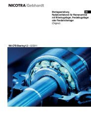
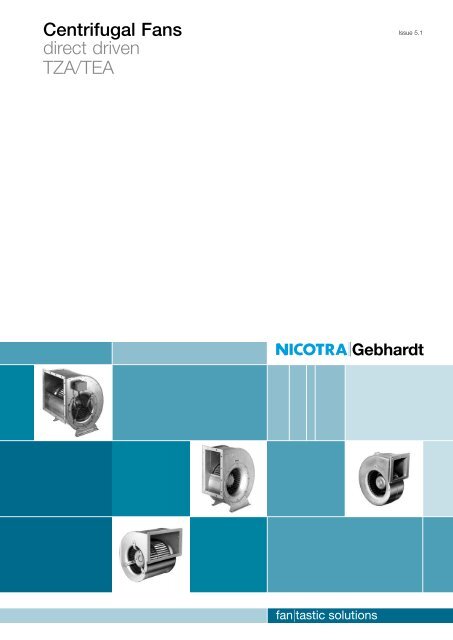
<strong>Centrifugal</strong> <strong>Fans</strong><br />
<strong>direct</strong> <strong>driven</strong><br />
<strong>TZA</strong>/<strong>TEA</strong><br />
Issue 5.1<br />
1
2<br />
<strong>TZA</strong> E1<br />
<strong>Centrifugal</strong> fans of the <strong>TZA</strong> E1 range find application<br />
e.g. in:<br />
fume extractor hoods,<br />
air-conditioning units,<br />
clean room systems,<br />
air purification equipment,<br />
welding-bench extractor systems,<br />
forced ventilation<br />
<strong>TZA</strong> 01<br />
<strong>Centrifugal</strong> fans of the <strong>TZA</strong> 01 range find use e.g. in:<br />
HVAC installations,<br />
warm-air installations,<br />
air curtain equipment,<br />
cooling of equipment<br />
Direct Driven <strong>Centrifugal</strong> <strong>Fans</strong> / <strong>TZA</strong> / Introduction
Single phase current<br />
230 V<br />
50 Hz<br />
1.15 kg/m³<br />
Three phase current<br />
400 V<br />
50 Hz<br />
1.15 kg/m³<br />
Fast selection <strong>TZA</strong> 01<br />
Here’s how you select: Possible fans:<br />
Pressure increase Δp t = 350 Pa <strong>TZA</strong> 01-0250-4E<br />
Volume q V = 4000 m³/h <strong>TZA</strong> 01-0280-4E<br />
With the selection diagram and a given duty point, a fast selection of the fan in question can be<br />
made. The represented performance curves are the respective performance curves of the fans at<br />
maximal speed.<br />
On the following pages you will find, ordered in increasing size, the complete technical data of the<br />
fans with individual performance curves.<br />
<strong>TZA</strong> E1 see following pages.<br />
Pa<br />
350<br />
∆ p t<br />
1000<br />
800<br />
600<br />
400<br />
200<br />
0<br />
V .<br />
0200-4E<br />
0225-4E<br />
0250-4E<br />
0280-4E<br />
3000 6000 9000<br />
4000<br />
Direct Driven <strong>Centrifugal</strong> <strong>Fans</strong> / <strong>TZA</strong> / Introduction<br />
<strong>TZA</strong> 01 ... E<br />
12000<br />
m³/h<br />
3
<strong>TZA</strong> E1-0080/-0130 230 V<br />
50 Hz<br />
Technical Data<br />
Curves Poles Voltage/<br />
Connection<br />
Frequency<br />
Speed max.<br />
power<br />
Nominal<br />
current<br />
qVmax LWA6 at<br />
Capacitor Protection/<br />
Temp.<br />
Weight Rotation Media<br />
<strong>direct</strong>ion temp.<br />
consumption qVopt class<br />
<strong>TZA</strong> E1- V Hz 1/min kW A m³/h dB mF ca. kg °C<br />
0080-2E [A1] 2 230, 1~ 50 1950 0.087 0.39 4100 66 2 2 IP20/B 1.5 RD -25...+40<br />
0112-2E [A2] 2 230, 1~ 50 1150 0.190 0.84 4550 64 3 IP44/B 4.4 RD -25...+40<br />
0130-4E [A4] 4 230, 1~ 50 1300 0.180 0.79 4550 71 5 IP44/B 4.5 RD -25...+40<br />
2 Capacitor according to protection class P2<br />
Curves<br />
∆ p t<br />
4<br />
Pa<br />
500<br />
400<br />
300<br />
200<br />
100<br />
0<br />
V .<br />
L WA<br />
[A1]<br />
66<br />
[A2]<br />
p d2<br />
64 dB<br />
200 400 600 800<br />
<strong>TZA</strong> E1 ...<br />
1000<br />
m³/h<br />
Pa<br />
∆ p t<br />
250<br />
200<br />
150<br />
100<br />
50<br />
0<br />
V .<br />
L WA<br />
Direct Driven <strong>Centrifugal</strong> <strong>Fans</strong> / <strong>TZA</strong> / Technical Data<br />
[A4]<br />
200 400 600 800<br />
Accessories<br />
Isolator Transformer Transformer Transformer Speed regulator Speed controller<br />
7 taps 5-steps electronic electronic electronic<br />
<strong>TZA</strong> 01- ESH ETO ETH EPH EPA EPA<br />
0080-2E ESH 21-0030-22 ETO 10-0018-5E ETH 31-0020-5E EPH 03-0010-5E EPA 03-0060-5E EPA 83-0060-5E<br />
0112-2E ESH 21-0030-22 ETO 10-0018-5E ETH 31-0020-5E EPH 03-0010-5E EPA 03-0060-5E EPA 83-0060-5E<br />
0130-4E ESH 21-0030-22 ETO 10-0018-5E ETH 31-0020-5E EPH 03-0010-5E EPA 03-0060-5E EPA 83-0060-5E<br />
1000<br />
r 1 =1.15 kg/m³<br />
For detailed descriptions and further controllers and regulators see section Accessories.<br />
The fans are delivered with a fitted connecting cable and a loosely enclosed operational capacitor. Length of the connecting cable see Dimensions.<br />
<strong>TZA</strong> E1 ...<br />
p d2<br />
71 dB<br />
1200<br />
1400<br />
m³/h
<strong>TZA</strong> E1-0080/-0130 230 V<br />
50 Hz<br />
Dimensions in mm, subject to change.<br />
<strong>TZA</strong> E1- a a1 a2 b b1 b2 b4 d1 h0 h5 h6 p q L<br />
0080-2E 100 67 88 180 145 168 146 5.5 181 162 68 86 63 200<br />
0112-2E<br />
0130-4E<br />
142 102 126 270 230 254 232 5.5 237 204 98 97 68 300<br />
see dimensional drawing<br />
<strong>TZA</strong> E1-0080/-0112<br />
<strong>TZA</strong> E1-0130<br />
1 delivered with loose flange and capacitor<br />
×<br />
LG RD<br />
Direction / Rotation<br />
Direct Driven <strong>Centrifugal</strong> <strong>Fans</strong> / <strong>TZA</strong> / Technical Data<br />
The <strong>direct</strong>ion of rotation is determined with the unit being seen from the motor connection (terminal box) side.<br />
<strong>Centrifugal</strong> fans <strong>TZA</strong> E1 are always manufactured in clockwise rotation RD.<br />
1 —<br />
Kabellänge<br />
5
<strong>TZA</strong> 01-0200 230/400 V<br />
50 Hz<br />
Technical Data<br />
<strong>TZA</strong> 01- V Hz 1/min kW A Pa m³/h dB mF ca. kg °C<br />
0200-4E• [B1] 4 230, 1~ 50 920 0.43 2.0 - 2260 71 10 IP44/F 13.5 -20...+40<br />
0200-4D• [B2] 4 400, 3~ 50 1030 0.54 1.0 - 2750 72 - IP44/F 13.5 -20...+40<br />
Curves<br />
6<br />
Curves Poles Voltage/ Fre- Speed max. Nominal Pressure q Vmax L WA6 Capaci- Protection/ Weight Media<br />
Connection quency power current increase at tor Temp. temp.<br />
consumption q Vopt class<br />
• (also) stepless speed controllable by tension variation<br />
Dimensions in mm, subject to change.<br />
256<br />
85 130<br />
242<br />
162<br />
89<br />
358<br />
168 190<br />
22<br />
22<br />
22<br />
286<br />
160<br />
309<br />
8<br />
ZKF 15 ZKE 15 200<br />
ZSG<br />
Direction / Rotation<br />
LG 0 LG 90 LG 180 LG 270<br />
228<br />
157<br />
167<br />
393<br />
Direct Driven <strong>Centrifugal</strong> <strong>Fans</strong> / <strong>TZA</strong> / Technical Data<br />
306<br />
286<br />
254<br />
2×90<br />
176 187<br />
The <strong>direct</strong>ion of rotation is determined with the unit being seen from the motor connection (terminal box) side.<br />
Anti-clockwise rotation, symbol LG.<br />
Double inlet fans are built in series in rotation <strong>direct</strong>ion LG.<br />
r 1 =1.15 kg/m³<br />
Accessories<br />
Anti vibration Motor protection Isolator Transformer Transformer Transformer Speed controller<br />
mounts unit 7 taps 5-steps electronic electronic<br />
<strong>TZA</strong> 01- 4 × ZBD ESM ESH ETO ETH EPA EPA<br />
0200-4E• ZBD 21-6035 ESM 01-0020-5E ESH 21-0030-25 ETO 10-0040-5E ETH 35-0040-5E EPA 03-0060-5E EPA 83-0060-5E<br />
0200-4D• ZBD 21-6035 ESM 01-0040-8D ESH 21-0030-65 ETO 10-0010-8D ETH 36-0010-8D – EPA 83-0050-8D<br />
7
<strong>TZA</strong> 94-0215 230 V<br />
50 Hz<br />
Technical Data<br />
<strong>TZA</strong> 94- V Hz 1/min kW A Pa m³/h dB mF ca. kg °C<br />
0215-4E• [C1] 4 230, 1~ 50 1340 0.71 3.5 - 2720 71 20 IP44/F 16 -20...+40<br />
Curves<br />
Curves Poles Voltage/ Fre- Speed max. Nominal Pressure q Vmax L WA6 Capaci- Protection/ Weight Media<br />
Connection quency power current increase at tor Temp. temp.<br />
consumption q Vopt class<br />
• (also) stepless speed controllable by tension variation<br />
Dimensions in mm, subject to change.<br />
164×288<br />
30 130<br />
62<br />
305<br />
154 151<br />
140 83<br />
172<br />
305<br />
133<br />
220<br />
198<br />
164<br />
140 83<br />
322<br />
ZKF ZKE 351<br />
7<br />
ZSG<br />
Direction / Rotation<br />
LG 0 LG 90 LG 180 LG 270<br />
Direct Driven <strong>Centrifugal</strong> <strong>Fans</strong> / <strong>TZA</strong> / Technical Data<br />
351<br />
322<br />
295<br />
2x100<br />
The <strong>direct</strong>ion of rotation is determined with the unit being seen from the motor connection (terminal box) side.<br />
Anti-clockwise rotation, symbol LG.<br />
Double inlet fans are built in series in rotation <strong>direct</strong>ion LG.<br />
2×100<br />
r 1 =1.15 kg/m³<br />
Accessories<br />
Anti vibration Motor protection Isolator Transformer Transformer Transformer Speed controller<br />
mounts unit 7 taps 5-steps electronic electronic<br />
<strong>TZA</strong> 94- 4 × ZBD ESM ESH ETO ETH EPA EPA<br />
0215-4E• ZBD 21-5935 ESM 01-0020-5E ESH 21-0030-25 ETO 10-0040-5E ETH 35-0040-5E EPA 03-0060-5E EPA 83-0060-5E<br />
10<br />
7
<strong>TZA</strong> 01-0225 230/400 V<br />
50 Hz<br />
Technical Data<br />
<strong>TZA</strong> 01- V Hz 1/min kW A Pa m³/h dB mF ca. kg °C<br />
0225-4E• [D1] 4 230, 1~ 50 1160 1.15 5.0 - 4100 76 25 IP44/F 19 -20...+40<br />
0225-4D• [D2] 4 400, 3~ 50 1260 1.30 2.5 - 4550 76 - IP44/F 19 -20...+40<br />
Curves<br />
8<br />
Curves Poles Voltage/ Fre- Speed max. Nominal Pressure q Vmax L WA6 Capaci- Protection/ Weight Media<br />
Connection quency power current increase at tor Temp. temp.<br />
consumption q Vopt class<br />
• (also) stepless speed controllable by tension variation<br />
Dimensions in mm, subject to change.<br />
288<br />
30 130<br />
274<br />
180<br />
100<br />
399<br />
191 212<br />
26<br />
26<br />
26<br />
322<br />
220<br />
348 10.5<br />
ZKF 15 ZKE 15 270<br />
ZSG<br />
Direction / Rotation<br />
LG 0 LG 90 LG 180 LG 270<br />
255<br />
176<br />
194<br />
447<br />
Direct Driven <strong>Centrifugal</strong> <strong>Fans</strong> / <strong>TZA</strong> / Technical Data<br />
348<br />
322<br />
286<br />
2×100<br />
176 205<br />
The <strong>direct</strong>ion of rotation is determined with the unit being seen from the motor connection (terminal box) side.<br />
Anti-clockwise rotation, symbol LG.<br />
Double inlet fans are built in series in rotation <strong>direct</strong>ion LG.<br />
r 1 =1.15 kg/m³<br />
Accessories<br />
Anti vibration Motor protection Isolator Transformer Transformer Transformer Speed controller<br />
mounts unit 7 taps 5-steps electronic electronic<br />
<strong>TZA</strong> 01- 4 × ZBD ESM ESH ETO ETH EPA EPA<br />
0225-4E• ZBD 21-5935 ESM 01-0020-5E ESH 21-0030-25 ETO 10-0070-5E ETH 35-0070-5E EPA 03-0060-5E EPA 83-0060-5E<br />
0225-4D• ZBD 21-5935 ESM 01-0040-8D ESH 21-0030-65 ETO 10-0040-8D ETH 36-0040-8D – EPA 83-0050-8D<br />
10
<strong>TZA</strong> 01-0250 230/400 V<br />
50 Hz<br />
Technical Data<br />
<strong>TZA</strong> 01- V Hz 1/min kW A Pa m³/h dB mF ca. kg °C<br />
0250-4E• [F1] 4 230, 1~ 50 1180 1.75 7.8 115 5000 79 30 IP44/F 31 -20...+40<br />
0250-4D• [F2] 4 400, 3~ 50 1140 1.68 2.9 115 5350 80 - IP44/F 26 -20...+40<br />
Curves<br />
Curves Poles Voltage/ Fre- Speed max. Nominal Pressure q Vmax L WA6 Capaci- Protection/ Weight Media<br />
Connection quency power current increase at tor Temp. temp.<br />
consumption q Vopt class<br />
• (also) stepless speed controllable by tension variation<br />
Dimensions in mm, subject to change.<br />
322<br />
30 130<br />
301<br />
198<br />
110<br />
438<br />
206 234<br />
28<br />
28<br />
28<br />
356<br />
220<br />
381 10.5<br />
ZKF 15 ZKE 15 270<br />
ZSG<br />
Direction / Rotation<br />
LG 0 LG 90 LG 180 LG 270<br />
282<br />
194<br />
210<br />
Direct Driven <strong>Centrifugal</strong> <strong>Fans</strong> / <strong>TZA</strong> / Technical Data<br />
490<br />
382<br />
356<br />
320<br />
3×100<br />
The <strong>direct</strong>ion of rotation is determined with the unit being seen from the motor connection (terminal box) side.<br />
Anti-clockwise rotation, symbol LG.<br />
Double inlet fans are built in series in rotation <strong>direct</strong>ion LG.<br />
222<br />
r 1 =1.15 kg/m³<br />
Accessories<br />
Anti vibration Motor protection Isolator Transformer Transformer Transformer Speed controller<br />
mounts unit 7 taps 5-steps electronic electronic<br />
<strong>TZA</strong> 01- 4 × ZBD ESM ESH ETO ETH EPA EPA<br />
0200-4E• ZBD 03-0806 ESM 01-0020-5E ESH 21-0030-25 ETO 10-0130-5E ETH 36-0200-5E EPA 03-0100-5E EPA 83-0100-5E<br />
0200-4D• ZBD 03-0806 ESM 01-0040-8D ESH 21-0030-65 ETO 10-0040-8D ETH 36-0040-8D – EPA 83-0050-8D<br />
10<br />
9
<strong>TZA</strong> 01-0280 230/400 V<br />
50 Hz<br />
Technical Data<br />
<strong>TZA</strong> 01- V Hz 1/min kW A Pa m³/h dB mF ca. kg °C<br />
0280-4E• [H1] 4 230, 1~ 50 1260 2.61 11.3 190 6670 82 50 IP44/F 48 -20...+40<br />
0280-4D• [H2] 4 400, 3~ 50 1260 2.15 3.8 350 5860 83 - IP44/F 39 -20...+40<br />
0280-6D• [H3] 4 400, 3~ 50 740 1.20 2.7 - 6250 75 - IP44/F 39 -20...+40<br />
Curves<br />
10<br />
Curves Poles Voltage/ Fre- Speed max. Nominal Pressure q Vmax L WA6 Capaci- Protection/ Weight Media<br />
Connection quency power current increase at tor Temp. temp.<br />
consumption q Vopt class<br />
• (also) stepless speed controllable by tension variation<br />
Dimensions in mm, subject to change.<br />
361<br />
30 130<br />
334<br />
221<br />
123<br />
484<br />
226 263<br />
30<br />
30<br />
30<br />
395<br />
220<br />
421 10.5<br />
ZKF 15 ZKE 15 270<br />
ZSG<br />
Direction / Rotation<br />
LG 0 LG 90 LG 180 LG 270<br />
315<br />
216<br />
236<br />
Direct Driven <strong>Centrifugal</strong> <strong>Fans</strong> / <strong>TZA</strong> / Technical Data<br />
548<br />
421<br />
395<br />
358<br />
3×100<br />
224 241<br />
The <strong>direct</strong>ion of rotation is determined with the unit being seen from the motor connection (terminal box) side.<br />
Anti-clockwise rotation, symbol LG.<br />
Double inlet fans are built in series in rotation <strong>direct</strong>ion LG.<br />
r 1 =1.15 kg/m³<br />
Accessories<br />
Anti vibration Motor protection Isolator Transformer Transformer Transformer Speed controller<br />
mounts unit 7 taps 5-steps electronic electronic<br />
<strong>TZA</strong> 01- 4 × ZBD ESM ESH ETO ETH EPA EPA<br />
0280-4E• ZBD 03-0806 – ESH 21-0030-25 ETO 10-0130-5E ETH 36-0200-5E – –<br />
0280-4D• ZBD 03-0806 ESM 01-0040-8D ESH 21-0030-65 ETO 10-0040-8D ETH 36-0040-8D – EPA 83-0050-8D<br />
0280-6D• ZBD 21-5935 ESM 01-0040-8D ESH 21-0030-65 ETO 10-0040-8D ETH 36-0040-8D – EPA 83-0050-8D<br />
10
<strong>TZA</strong> 01-0315 400 V<br />
50 Hz<br />
Technical Data<br />
<strong>TZA</strong> 01- V Hz 1/min kW A Pa m³/h dB mF ca. kg °C<br />
0315-4D• [K1] 4 400, 3~ 50 1250 4.95 9.0 95 10500 86 - IP44/F 59 -20...+40<br />
0315-6D• [K2] 4 400, 3~ 50 750 1.66 3.4 110 7000 78 - IP44/F 43 -20...+40<br />
Curves<br />
Curves Poles Voltage/ Fre- Speed max. Nominal Pressure q Vmax L WA6 Capaci- Protection/ Weight Media<br />
Connection quency power current increase at tor Temp. temp.<br />
consumption q Vopt class<br />
• (also) stepless speed controllable by tension variation<br />
Dimensions in mm, subject to change.<br />
404<br />
30 130<br />
371<br />
248<br />
139<br />
536<br />
247 294<br />
33<br />
33<br />
33<br />
438<br />
220<br />
463 10.5<br />
ZKF 15 ZKE 15 270<br />
ZSG<br />
Direction / Rotation<br />
LG 0 LG 90 LG 180 LG 270<br />
355<br />
242<br />
253<br />
Direct Driven <strong>Centrifugal</strong> <strong>Fans</strong> / <strong>TZA</strong> / Technical Data<br />
603<br />
464<br />
438<br />
401<br />
3x100<br />
The <strong>direct</strong>ion of rotation is determined with the unit being seen from the motor connection (terminal box) side.<br />
Anti-clockwise rotation, symbol LG.<br />
Double inlet fans are built in series in rotation <strong>direct</strong>ion LG.<br />
285<br />
r 1 =1.15 kg/m³<br />
Accessories<br />
Anti vibration Motor protection Isolator Transformer Transformer Transformer Speed controller<br />
mounts unit 7 taps 5-steps electronic electronic<br />
<strong>TZA</strong> 01- 4 × ZBD ESM ESH ETO ETH EPA EPA<br />
0315-4D• ZBD 03-1007 – ESH 21-0075-65 ETO 10-0150-8D ETH 36-0140-8D – EPA 83-0100-8D<br />
0315-6D• ZBD 03-0806 ESM 01-0040-8D ESH 21-0030-65 ETO 10-0040-8D ETH 36-0040-8D – EPA 83-0050-8D<br />
10<br />
11
<strong>TZA</strong> 01-0355 400 V<br />
50 Hz<br />
Technical Data<br />
<strong>TZA</strong> 01- V Hz 1/min kW A Pa m³/h dB mF ca. kg °C<br />
0355-4D• [L1] 4 400, 3~ 50 1270 4.50 8.1 675 8760 90 - IP44/F 66 -20...+40<br />
0355-6D [L2] 4 400, 3~ 50 810 2.62 4.8 225 9330 82 - IP44/F 62 -20...+40<br />
Curves<br />
12<br />
Curves Poles Voltage/ Fre- Speed max. Nominal Pressure q Vmax L WA6 Capaci- Protection/ Weight Media<br />
Connection quency power current increase at tor Temp. temp.<br />
consumption q Vopt class<br />
• (also) stepless speed controllable by tension variation<br />
Dimensions in mm, subject to change.<br />
453<br />
30 130<br />
414<br />
279<br />
157<br />
598<br />
273 329<br />
36<br />
36<br />
36<br />
487<br />
220<br />
513 10.5<br />
ZKF 15 ZKE 15 270<br />
ZSG<br />
Direction / Rotation<br />
LG 0 LG 90 LG 180 LG 270<br />
397<br />
271<br />
275<br />
Direct Driven <strong>Centrifugal</strong> <strong>Fans</strong> / <strong>TZA</strong> / Technical Data<br />
668<br />
513<br />
487<br />
450<br />
4×100<br />
The <strong>direct</strong>ion of rotation is determined with the unit being seen from the motor connection (terminal box) side.<br />
Anti-clockwise rotation, symbol LG.<br />
Double inlet fans are built in series in rotation <strong>direct</strong>ion LG.<br />
287<br />
r 1 =1.15 kg/m³<br />
Accessories<br />
Anti vibration Motor protection Isolator Transformer Transformer Transformer Speed controller<br />
mounts unit 7 taps 5-steps electronic electronic<br />
<strong>TZA</strong> 01- 4 × ZBD ESM ESH ETO ETH EPA EPA<br />
0355-4D• ZBD 03-1007 – ESH 21-0075-65 ETO 10-0150-8D ETH 36-0140-8D – EPA 83-0100-8D<br />
0355-6D ZBD 03-0806 ESM 01-0040-8D ESH 21-0030-65 – – – –<br />
10
proSELECTA II<br />
proSELECTA II is a technical selection program that allows you to configure your own individually designed<br />
fan. It provides you with the opportunity to choose from the entire range of fan types and their<br />
associated options.<br />
Simple and reliable selection<br />
The result from proSELECTA II is the provision of all the<br />
technical data for your fan, including sound level data, dimension<br />
specifications and accessories. Apart from that, as a registered<br />
user, your purchase prices are provided. Additionally<br />
fully dimensioned drawings in dxf format are available, which<br />
can be downloaded and transferred straight into your CAD<br />
system.<br />
So that you can be sure<br />
Models and options that are technically not permissible, are automatically excluded in proSELECTA II. So<br />
there is no chance that you will configure a “wrong” device option.<br />
What else is important to you<br />
During the fan selection process, you can choose any of the standardised ATEX options.<br />
Free registration and many advantages<br />
You can register as a proSELECTA II user with us, which enables us to offer you faster order processing.<br />
What this means for you is:<br />
• The complete configuration of your fan with its<br />
associated system accessories and belt drive<br />
layout.<br />
• The possibility to produce fans that operate via<br />
a frequency inverter.<br />
• The option of saving your own fan configuration<br />
on our server.<br />
• The opportunity to modify your saved configuration,<br />
even over the phone to your <strong>Nicotra</strong>-<br />
<strong>Gebhardt</strong> representative.<br />
13
14<br />
<strong>TEA</strong> E1<br />
<strong>Centrifugal</strong> fans of the <strong>TEA</strong> E1 range find application<br />
e.g. in:<br />
control cabinet cooling,<br />
projector cooling,<br />
dust extraction systems,<br />
forced ventilation,<br />
data processing machines<br />
<strong>TEA</strong> 01<br />
<strong>Centrifugal</strong> fans of the <strong>TEA</strong> 01 range find application<br />
e.g. in:<br />
ventilating systems,<br />
HVAC installations,<br />
cooling of equipment,<br />
warm-air installations<br />
Direct Driven <strong>Centrifugal</strong> <strong>Fans</strong> / <strong>TEA</strong> / Introduction
Single phase current<br />
230 V<br />
50 Hz<br />
1.15 kg/m³<br />
Three phase current<br />
400 V<br />
50 Hz<br />
1.15 kg/m³<br />
Fast selection <strong>TEA</strong> 01<br />
Here’s how you select: Possible fans:<br />
Pressure increase Δpt = 370 Pa <strong>TZA</strong> 01-0280-4E<br />
Volume qV = 2500 m³/h<br />
With the selection diagram and a given duty point, a fast selection of the fan in question can be<br />
made. The represented performance curves are the respective performance curves of the fans at<br />
maximal speed.<br />
On the following pages you will find, ordered in increasing size, the complete technical data of the<br />
fans with individual performance curves.<br />
<strong>TEA</strong> E1 see following pages.<br />
Pa<br />
370<br />
∆ p t<br />
700<br />
600<br />
500<br />
400<br />
300<br />
200<br />
100<br />
0<br />
V .<br />
0200-4E<br />
0225-4E 0250-4E<br />
0280-4E<br />
1000 2000 3000<br />
Direct Driven <strong>Centrifugal</strong> <strong>Fans</strong> / <strong>TEA</strong> / Introduction<br />
2500<br />
4000<br />
<strong>TEA</strong> 01 ... 4E<br />
5000<br />
m³/h<br />
15
<strong>TEA</strong> E1-0060/-0150 230 V<br />
50 Hz<br />
Technical Data<br />
Curves Poles Voltage/<br />
Connection<br />
Frequency Speed max.<br />
power<br />
Nominal<br />
current<br />
qVmax LWA6 at<br />
Capacitor<br />
Protection/<br />
Temp.<br />
Weight Rotation Media<br />
<strong>direct</strong>ion temp.<br />
consumption qVopt class<br />
<strong>TEA</strong> E1- V Hz 1/min kW A m³/h dB mF ca. kg °C<br />
0060-2E [A1] 2 230, 1~ 50 1850 0.024 0.13 62 58 - IP44/F 0.8 LG -20...+40<br />
0090-2E [A2] 2 230, 1~ 50 1650 0.041 0.19 155 62 1.5 2 IP44/B 1.3 LG -20...+40<br />
0100-2E [A3] 2 230, 1~ 50 2350 0.080 0.35 255 69 2 IP44/B 1.8 LG -20...+40<br />
0125-2E [A4] 2 230, 1~ 50 1650 0.135 0.60 385 71 2 IP44/B 3.0 LG -20...+40<br />
0130-2E [A5] 2 230, 1~ 50 2100 0.240 1.05 600 80 6 IP44/B 3.9 LG -20...+40<br />
0150-4E [A6] 4 230, 1~ 50 1250 0.110 0.49 575 73 3 IP44/B 3.7 LG -20...+40<br />
2 Capacitor according to protection class P2<br />
Curves<br />
Pa<br />
∆ p t<br />
16<br />
600<br />
500<br />
400<br />
300<br />
200<br />
100<br />
0<br />
L WA<br />
0060-2E<br />
V .<br />
58<br />
0090-2E<br />
62<br />
0125-2E<br />
0100-2E<br />
69<br />
0130-2E<br />
71<br />
p d2<br />
<strong>TEA</strong> E1 ...<br />
100 200 300 400 500 600<br />
80 dB<br />
m³/h<br />
700<br />
Pa<br />
∆ p t<br />
300<br />
250<br />
200<br />
150<br />
100<br />
50<br />
0<br />
V .<br />
LWA<br />
Direct Driven <strong>Centrifugal</strong> <strong>Fans</strong> / <strong>TEA</strong> / Technical Data<br />
0150-4E<br />
pd2<br />
<strong>TEA</strong> E1 ...<br />
73 dB<br />
100 200 300 400 500 600<br />
Accessories<br />
Isolator Transformer Transformer Transformer Speed regulator Speed controller<br />
7 taps 5-steps electronic electronic electronic<br />
<strong>TEA</strong> E1- ESH ETO ETH EPH EPA EPA<br />
0060-2E ESH 21-0030-22 ETO 10-0018-5E ETH 31-0020-5E EPH 03-0010-5E – –<br />
0090-2E ESH 21-0030-22 ETO 10-0018-5E ETH 31-0020-5E EPH 03-0010-5E – –<br />
0100-2E ESH 21-0030-22 ETO 10-0018-5E ETH 31-0020-5E EPH 03-0010-5E EPA 03-0060-5E EPA 83-0060-5E<br />
0125-2E ESH 21-0030-22 ETO 10-0018-5E ETH 31-0020-5E EPH 03-0010-5E EPA 03-0060-5E EPA 83-0060-5E<br />
0130-2E ESH 21-0030-22 ETO 10-0018-5E ETH 31-0020-5E EPH 03-0020-5E EPA 03-0060-5E EPA 83-0060-5E<br />
0150-4E ESH 21-0030-22 ETO 10-0018-5E ETH 31-0020-5E EPH 03-0010-5E EPA 03-0060-5E EPA 83-0060-5E<br />
r 1 =1.15 kg/m³<br />
For detailed descriptions and further controllers and regulators see section Accessories.<br />
The fans are delivered with a fitted connecting cable and a loosely enclosed operational capacitor. Length of the connecting cable see Dimensions.<br />
m³/h<br />
700
<strong>TEA</strong> E1-0060/-0150 230 V<br />
50 Hz<br />
Dimensions in mm, subject to change.<br />
<strong>TEA</strong> E1- a a1 a2 b b1 b2 b4 d1 d3 h0 h5 h6 p q z×M L<br />
0060-2E see dimensional drawing<br />
0090-2E 83 50 66 115 76 97 82 8.0 118 183 159 71 79 71 4×M4 300<br />
0100-2E 83 50 68 115 76 100 98 7.0 132 190 174 82 82 67 4×M4 450<br />
0125-2E 120 92 105 130 94 115 100 6.3 158 261 226 107 103 94 4×M4 450<br />
0130-2E 120 92 105 130 94 115 100 6.3 175 261 226 107 103 94 4×M4 450<br />
0150-4E 140 110 120 125 86 110 105 7.0 194 294 261 123 120 101 4×M4 450<br />
<strong>TEA</strong> E1-0090/-0150<br />
<strong>TEA</strong> E1-0060<br />
68<br />
58<br />
42<br />
76<br />
71,5<br />
66<br />
56<br />
80<br />
5,5<br />
4,5<br />
34,5<br />
300<br />
118<br />
60<br />
3×M4<br />
×<br />
The <strong>direct</strong>ion of rotation is determined with the unit being seen from the motor connection (terminal box) side.<br />
Anti-clockwise rotation, symbol LG.<br />
Single inlet fans <strong>TEA</strong> E1 are built in series in rotation <strong>direct</strong>ion LG.<br />
Direction / Rotation<br />
LG RD<br />
Direct Driven <strong>Centrifugal</strong> <strong>Fans</strong> / <strong>TEA</strong> / Technical Data<br />
84<br />
39<br />
55<br />
128<br />
Cable<br />
length<br />
17
<strong>TEA</strong> 01-0200 230/400 V<br />
50 Hz<br />
Technical Data<br />
<strong>TEA</strong> 01- V Hz 1/min kW A Pa m³/h dB mF ca. kg °C<br />
0200-4E• [A1] 4 230, 1~ 50 1060 0.21 0.98 50 1065 66 4 IP44/F 10 -20...+40<br />
0200-4D• [A2] 4 230/400, 3~ Y 50 1190 0.30 0.92/0.53 - 1370 67 - IP44/F 10 -20...+40<br />
Curves<br />
18<br />
Curves Poles Voltage/ Fre- Speed max. Nominal Pressure q Vmax L WA6 Capaci- Protection/ Weight Media<br />
Connection quency power current increase at tor Temp. temp.<br />
consumption q Vopt class<br />
• (also) stepless speed controllable by tension variation<br />
H not achievable in this area<br />
Dimensions in mm, subject to change.<br />
The photo shows the fan using<br />
RD 90.<br />
256x131<br />
<br />
<br />
242<br />
89<br />
<br />
<br />
<br />
<br />
<br />
<br />
<br />
162<br />
<br />
<br />
<br />
<br />
<br />
358<br />
168 190<br />
22<br />
235<br />
<br />
<br />
<br />
<br />
<br />
<br />
<br />
8<br />
25 130<br />
22<br />
90<br />
160<br />
130<br />
25<br />
ZKF 16 ZKE 16<br />
160<br />
200<br />
This drawing shows the fan<br />
using RD 90.<br />
184<br />
ZSG ZKE 11 ZKF 11<br />
Direction / Rotation<br />
<br />
22<br />
157<br />
167 228<br />
393<br />
Direct Driven <strong>Centrifugal</strong> <strong>Fans</strong> / <strong>TEA</strong> / Technical Data<br />
306<br />
286<br />
254<br />
2x90<br />
126<br />
181<br />
161<br />
129<br />
7<br />
235<br />
255<br />
r 1 =1.15 kg/m³<br />
LG 0 LG 90 LG 180 LG 270 RD 0 RD 90 RD 180 RD 270<br />
The <strong>direct</strong>ion of rotation is determined with the unit being seen from the motor connection (terminal box) side.<br />
Anti-clockwise rotation, symbol LG. Clockwise rotation symbol RD.<br />
Accessories<br />
Anti vibration Motor protection Isolator Transformer Transformer Transformer Speed controller<br />
mounts unit 7 taps 5-steps electronic electronic<br />
<strong>TEA</strong> 01- 4 × ZBD ESM ESH ETO ETH EPA EPA<br />
0200-4E• ZBD 21-6035 ESM 01-0020-5E ESH 21-0030-25 ETO 10-0018-5E ETH 35-0040-5E EPA 03-0060-5E EPA 83-0060-5E<br />
0200-4D• ZBD 21-6035 ESM 01-0040-8D ESH 21-0030-35 ETO 10-0010-8D ETH 35-0010-8D – EPA 83-0050-8D<br />
6x 7<br />
205
<strong>TEA</strong> 01-0225 230/400 V<br />
50 Hz<br />
Technical Data<br />
<strong>TEA</strong> 01- V Hz 1/min kW A Pa m³/h dB mF ca. kg °C<br />
0225-4E• [B1] 4 230, 1~ 50 1230 0.48 2.50 - 1760 70 - IP44/F 59 -20...+40<br />
0225-4D• [B2] 4 230/400, 3~ Y 50 1270 0.55 1.74/1.00 - 1950 72 - IP44/F 43 -20...+40<br />
Curves<br />
<br />
<br />
<br />
<br />
<br />
<br />
<br />
<br />
<br />
<br />
<br />
<br />
<br />
Curves Poles Voltage/ Fre- Speed max. Nominal Pressure q Vmax L WA6 Capaci- Protection/ Weight Media<br />
Connection quency power current increase at tor Temp. temp.<br />
consumption q Vopt class<br />
• (also) stepless speed controllable by tension variation<br />
<br />
<br />
H not achievable in this area<br />
<br />
<br />
<br />
<br />
<br />
<br />
<br />
<br />
<br />
Dimensions in mm, subject to change.<br />
The photo shows the fan using<br />
RD 90.<br />
288x146<br />
<br />
<br />
274<br />
100<br />
<br />
<br />
<br />
<br />
<br />
<br />
<br />
<br />
<br />
180<br />
<br />
<br />
<br />
<br />
<br />
<br />
<br />
<br />
<br />
<br />
399<br />
191 212<br />
26<br />
259<br />
<br />
26<br />
176<br />
194 255<br />
447<br />
348<br />
322<br />
286<br />
2x100<br />
8<br />
30 130<br />
26<br />
100<br />
182<br />
130<br />
25<br />
ZKF 16 ZKE 16<br />
220<br />
270<br />
This drawing shows the fan<br />
using RD 90.<br />
206<br />
ZSG ZKE 11 ZKF 11<br />
Direction / Rotation<br />
Direct Driven <strong>Centrifugal</strong> <strong>Fans</strong> / <strong>TEA</strong> / Technical Data<br />
134<br />
206<br />
180<br />
144<br />
10<br />
259<br />
279<br />
r 1 =1.15 kg/m³<br />
LG 0 LG 90 LG 180 LG 270 RD 0 RD 90 RD 180 RD 270<br />
The <strong>direct</strong>ion of rotation is determined with the unit being seen from the motor connection (terminal box) side.<br />
Anti-clockwise rotation, symbol LG. Clockwise rotation symbol RD.<br />
Accessories<br />
Anti vibration Motor protection Isolator Transformer Transformer Transformer Speed controller<br />
mounts unit 7 taps 5-steps electronic electronic<br />
<strong>TEA</strong> 01- 4 × ZBD ESM ESH ETO ETH EPA EPA<br />
0225-4E• ZBD 21-6035 ESM 01-0020-5E ESH 21-0030-25 ETO 10-0040-5E ETH 35-0040-5E EPA 03-0060-5E EPA 83-0060-5E<br />
0225-4D• ZBD 21-6035 ESM 01-0040-8D ESH 21-0030-35 ETO 10-0010-8D ETH 35-0010-8D – EPA 83-0050-8D<br />
6x 7<br />
229<br />
19
<strong>TEA</strong> 01-0250 230/400 V<br />
50 Hz<br />
Technical Data<br />
<strong>TEA</strong> 01- V Hz 1/min kW A Pa m³/h dB mF ca. kg °C<br />
0250-4E• [D1] 4 230, 1~ 50 1290 0.77 3.90 - 2305 73 - IP44/F 19 -20...+40<br />
0250-4D• [D2] 4 230/400, 3~ Y 50 1100 0.69 2.47/1.42 - 2500 73 - IP44/F 19 -20...+40<br />
Curves<br />
20<br />
<br />
<br />
<br />
<br />
<br />
<br />
<br />
<br />
<br />
<br />
<br />
<br />
<br />
<br />
Curves Poles Voltage/ Fre- Speed max. Nominal Pressure q Vmax L WA6 Capaci- Protection/ Weight Media<br />
Connection quency power current increase at tor Temp. temp.<br />
consumption q Vopt class<br />
• (also) stepless speed controllable by tension variation<br />
<br />
<br />
H not achievable in this area<br />
<br />
<br />
<br />
<br />
<br />
<br />
<br />
<br />
<br />
Dimensions in mm, subject to change.<br />
The photo shows the fan using<br />
RD 90.<br />
322x164<br />
301<br />
110<br />
198<br />
438<br />
206 234<br />
28<br />
286<br />
28<br />
194<br />
210 282<br />
490<br />
382<br />
356<br />
320<br />
3x100<br />
10,5<br />
30 130<br />
28<br />
100<br />
198<br />
130<br />
25<br />
ZKF 16 ZKE 16<br />
220<br />
270<br />
This drawing shows the fan<br />
using RD 90.<br />
223<br />
ZSG ZKE 11 ZKF 11<br />
Direction / Rotation<br />
Direct Driven <strong>Centrifugal</strong> <strong>Fans</strong> / <strong>TEA</strong> / Technical Data<br />
143<br />
224<br />
198<br />
162<br />
10<br />
286<br />
306<br />
r 1 =1.15 kg/m³<br />
LG 0 LG 90 LG 180 LG 270 RD 0 RD 90 RD 180 RD 270<br />
The <strong>direct</strong>ion of rotation is determined with the unit being seen from the motor connection (terminal box) side.<br />
Anti-clockwise rotation, symbol LG. Clockwise rotation symbol RD.<br />
Accessories<br />
Anti vibration Motor protection Isolator Transformer Transformer Transformer Speed controller<br />
mounts unit 7 taps 5-steps electronic electronic<br />
<strong>TEA</strong> 01- 4 × ZBD ESM ESH ETO ETH EPA EPA<br />
0250-4E• ZBD 21-5935 ESM 01-0020-5E ESH 21-0030-25 ETO 10-0040-5E ETH 35-0040-5E EPA 03-0060-5E EPA 83-0060-5E<br />
0250-4D• ZBD 21-5935 ESM 01-0040-8D ESH 21-0030-35 ETO 10-0020-8D ETH 35-0020-8D – EPA 83-0050-8D<br />
6x 7<br />
256
<strong>TEA</strong> 01-0280 230/400 V<br />
50 Hz<br />
Technical Data<br />
<strong>TEA</strong> 01- V Hz 1/min kW A Pa m³/h dB mF ca. kg °C<br />
0280-4E• [F1] 4 230, 1~ 50 1250 1.20 5.50 145 3050 77 - IP44/F 27 -20...+40<br />
0280-4D• [F2] 4 230/400, 3~ Y 50 1280 1.40 4.50/2.60 100 3540 78 - IP44/F 27 -20...+40<br />
Curves<br />
Curves Poles Voltage/ Fre- Speed max. Nominal Pressure q Vmax L WA6 Capaci- Protection/ Weight Media<br />
Connection quency power current increase at tor Temp. temp.<br />
consumption q Vopt class<br />
• (also) stepless speed controllable by tension variation<br />
H not achievable in this area<br />
Dimensions in mm, subject to change.<br />
The photo shows the fan using<br />
RD 90.<br />
361x183<br />
334<br />
123<br />
221<br />
484<br />
226 263<br />
30<br />
322<br />
30<br />
216<br />
236 315<br />
548<br />
421<br />
395<br />
358<br />
3x100<br />
10,5<br />
30 130<br />
30<br />
100<br />
219<br />
130<br />
30<br />
ZKF 16 ZKE 16<br />
220<br />
270<br />
This drawing shows the fan<br />
using RD 90.<br />
243<br />
ZSG ZKE 11 ZKF 11<br />
Direction / Rotation<br />
Direct Driven <strong>Centrifugal</strong> <strong>Fans</strong> / <strong>TEA</strong> / Technical Data<br />
LG 0 LG 90 LG 180 LG 270 RD 0 RD 90 RD 180 RD 270<br />
The <strong>direct</strong>ion of rotation is determined with the unit being seen from the motor connection (terminal box) side.<br />
Anti-clockwise rotation, symbol LG. Clockwise rotation symbol RD.<br />
152<br />
243<br />
217<br />
181<br />
10<br />
322<br />
348<br />
r 1 =1.15 kg/m³<br />
Accessories<br />
Anti vibration Motor protection Isolator Transformer Transformer Transformer Speed controller<br />
mounts unit 7 taps 5-steps electronic electronic<br />
<strong>TEA</strong> 01- 4 × ZBD ESM ESH ETO ETH EPA EPA<br />
0280-4E• ZBD 03-0806 ESM 01-0020-5E ESH 21-0030-25 ETO 10-0070-5E ETH 35-0070-5E EPA 03-0060-5E EPA 83-0060-5E<br />
0280-4D• ZBD 03-0806 ESM 01-0040-8D ESH 21-0030-35 ETO 10-0040-8D ETH 36-0040-8D – EPA 83-0050-8D<br />
8x 9,5<br />
288<br />
21
<strong>TEA</strong> 01-0315 230/400 V<br />
50 Hz<br />
Technical Data<br />
<strong>TEA</strong> 01- V Hz 1/min kW A Pa m³/h dB mF ca. kg °C<br />
0315-4D• [H1] 4 230/400, 3~ Y 50 1300 2.00 6.30/3.65 145 4290 79 - IP44/F 34 -20...+40<br />
Curves<br />
22<br />
Curves Poles Voltage/ Fre- Speed max. Nominal Pressure q Vmax L WA6 Capaci- Protection/ Weight Media<br />
Connection quency power current increase at tor Temp. temp.<br />
consumption q Vopt class<br />
• (also) stepless speed controllable by tension variation<br />
H not achievable in this area<br />
Dimensions in mm, subject to change.<br />
The photo shows the fan using<br />
RD 90.<br />
404x205<br />
371<br />
139<br />
248<br />
536<br />
247 294<br />
33<br />
356<br />
33<br />
242<br />
253 355<br />
603<br />
464<br />
438<br />
401<br />
3x100<br />
10,5<br />
30 130<br />
33<br />
100<br />
241<br />
130<br />
30<br />
ZKF 16 ZKE 16<br />
220<br />
270<br />
This drawing shows the fan<br />
using RD 90.<br />
264<br />
ZSG ZKE 11 ZKF 11<br />
Direction / Rotation<br />
Direct Driven <strong>Centrifugal</strong> <strong>Fans</strong> / <strong>TEA</strong> / Technical Data<br />
LG 0 LG 90 LG 180 LG 270 RD 0 RD 90 RD 180 RD 270<br />
The <strong>direct</strong>ion of rotation is determined with the unit being seen from the motor connection (terminal box) side.<br />
Anti-clockwise rotation, symbol LG. Clockwise rotation symbol RD.<br />
163<br />
265<br />
239<br />
203<br />
10<br />
356<br />
382<br />
r 1 =1.15 kg/m³<br />
Accessories<br />
Anti vibration Motor protection Isolator Transformer Transformer Transformer Speed controller<br />
mounts unit 7 taps 5-steps electronic electronic<br />
<strong>TEA</strong> 01- 4 × ZBD ESM ESH ETO ETH EPA EPA<br />
0315-4D• ZBD 03-0806 ESM 01-0040-8D ESH 21-0030-35 ETO 10-0010-8D ETH 36-0040-8D – EPA 83-0050-8D<br />
8x 9,5<br />
322
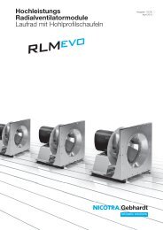
The new catalogue for<br />
Direct <strong>driven</strong> centrifugal fans<br />
High performance centrifugal fans DDM<br />
double width, double inlet, (DWDI),<br />
with built-in, optimised external rotor motor,<br />
made of galvanised sheet steel;<br />
available in various models;<br />
Impeller with forward curved blades of galvanised steel plate<br />
High performance centrifugal fans DDMB<br />
double width, double inlet, (DWDI),<br />
with built-in, brushless-DC external rotor motor and external commutation unit,<br />
made of galvanised sheet steel;<br />
available in various models;<br />
Impeller with forward curved blades of galvanised steel plate<br />
High performance centrifugal fans DD<br />
double width, double inlet, (DWDI),<br />
built-in, optimised internal rotor motor,<br />
made of galvanised sheet steel;<br />
available in various models;<br />
Impeller with forward curved blades of galvanised steel plate<br />
High performance centrifugal fans RZA rotavent<br />
double inlet,<br />
with built-in, low-slip external rotor motor,<br />
made of galvanised sheet steel or welded and coated,<br />
with multi position feet and connecting flange at discharge;<br />
Impeller with true aerofoil blades, welded and painted – system rotavent<br />
High performance centrifugal fans RZP<br />
double inlet,<br />
with built-in, brushless-DC external rotor motor and external commutation unit,<br />
made of galvanised sheet steel;<br />
with multi position feet and connecting flange at discharge;<br />
Impeller with true aerofoil blades, welded and painted – system<br />
High performance centrifugal fans RZM rotavent<br />
double inlet,<br />
fan with <strong>direct</strong>ly coupled motor fitted on pedestal and base frame,<br />
made of galvanised sheet steel with heavy duty reinforced side frame,<br />
connecting flange at discharge,<br />
Impeller with true aerofoil blades, welded and painted – system rotavent<br />
High performance centrifugal fans REM/TEM<br />
single inlet, with flanged IEC standard motor out of air stream,<br />
in unterschiedlichen Ausführungsvarianten,<br />
Impeller with true aerofoil blades, welded and painted (REM)<br />
or forward curved blades of galvanised steel plate (TEM),<br />
with or without pedestal for horizontal or vertical mounting<br />
High performance plug fans RLM<br />
optimised for use without scroll.<br />
Motor impeller with inlet cone,<br />
motor base and basic frame manufactured as a module and adjusted<br />
High performance plug fans RLE<br />
optimised for use without scroll.<br />
Vier unterschiedliche Laufradbaureihen,<br />
built-in, AC or brushless-DC external rotor motor,<br />
Inlet cone as an option<br />
23
<strong>TZA</strong><br />
Specifications<br />
Fan type<br />
Volume<br />
.<br />
V<br />
Total pressure increase Δpt Speed n<br />
Power consumption P1max Sound power level LWA Media temperature t<br />
Weight m<br />
24<br />
<strong>TZA</strong> E1-0080/-0130 <strong>TZA</strong> 01-0200/-0355 <strong>TZA</strong> 94-0215<br />
High performance-<br />
<strong>Centrifugal</strong> fans<br />
<strong>TZA</strong> E1<br />
- double inlet with <strong>direct</strong> drive<br />
- Casing made of galvanized sheet<br />
steel (<strong>TZA</strong> E1-0130-4E with loose<br />
flange and capacitor)<br />
- Impeller multivane with forward<br />
curved profiled blades<br />
- Impeller fitted to the shaft of a variable<br />
speed integral motor<br />
- Motor in protection class IP 44<br />
(<strong>TZA</strong> E1-0080-2E in protection<br />
class IP 20) completely maintenance<br />
free<br />
- statically and dynamically balanced<br />
- built-in thermalcontacts for motor<br />
protection<br />
- fitted connecting cable<br />
- capacitor loosely enclosed<br />
- Single phase current 230 V, 50 Hz<br />
<strong>TZA</strong> E1-<br />
= . . . . . . . . . . . . . . . . . . m³/h<br />
= . . . . . . . . . . . . . . . . . . Pa<br />
= . . . . . . . . . . . . . . . . . . 1/min<br />
= . . . . . . . . . . . . . . . . . . kW<br />
= . . . . . . . . . . . . . . . . . . dB(A)<br />
= . . . . . . . . . . . . . . . . . . °C<br />
= . . . . . . . . . . . . . . . . . . kg<br />
Accessories (extra cost)<br />
k Contact protection screen for inlet side<br />
by request<br />
k Isolator<br />
k Transformer stepped/stepless<br />
k Speed controller<br />
stepless, electronic<br />
k Temperature sensor<br />
High performance-<br />
<strong>Centrifugal</strong> fans<br />
<strong>TZA</strong> 01<br />
- double inlet with <strong>direct</strong> drive<br />
- Lock formed scroll casing made of<br />
galvanized sheet steel with bolted<br />
on, interchangeable feet<br />
- Impeller multivane with forward<br />
curved profiled blades<br />
- Impeller fitted to the shaft of a variable<br />
speed integral motor<br />
- Motor in protection class IP 54<br />
completely maintenance free<br />
- statically and dynamically balanced<br />
- anti-vibration suspension<br />
- built-in thermalcontacts for motor<br />
protection<br />
- terminal box ready for connection<br />
- Three phase current 400 V, 50 Hz<br />
bzw. Single phase current 230 V,<br />
50 Hz<br />
<strong>TZA</strong> 01-<br />
= . . . . . . . . . . . . . . . . . . m³/h<br />
= . . . . . . . . . . . . . . . . . . Pa<br />
= . . . . . . . . . . . . . . . . . . 1/min<br />
= . . . . . . . . . . . . . . . . . . kW<br />
= . . . . . . . . . . . . . . . . . . dB(A)<br />
= . . . . . . . . . . . . . . . . . . °C<br />
= . . . . . . . . . . . . . . . . . . kg<br />
Accessories (extra cost)<br />
k Discharge flange<br />
k Discharge flex<br />
k Inlet protection guards<br />
k Drain plugs<br />
k Inspection door<br />
k Anti-vibration mounts<br />
k Motor fullprotection unit<br />
k Isolator<br />
k Transformer stepped/stepless<br />
k Speed controller<br />
stepless, electronic<br />
k Temperature sensor<br />
Direct Driven <strong>Centrifugal</strong> <strong>Fans</strong> / <strong>TZA</strong> / Description<br />
High performance-<br />
<strong>Centrifugal</strong> fans<br />
<strong>TZA</strong> 94<br />
- double inlet with <strong>direct</strong> drive<br />
- Lock formed scroll casing made<br />
of galvanized sheet steel with interchangeable<br />
rectangular special<br />
casing<br />
- Impeller multivane with forward<br />
curved profiled blades<br />
- Impeller fitted to the shaft of a variable<br />
speed integral motor<br />
- Motor in protection class IP 54<br />
completely maintenance free<br />
- statically and dynamically balanced<br />
- anti-vibration suspension<br />
- built-in thermalcontacts for motor<br />
protection<br />
- terminal box ready for connection<br />
- Single phase current 230 V, 50 Hz<br />
<strong>TZA</strong> 94-<br />
= . . . . . . . . . . . . . . . . . . m³/h<br />
= . . . . . . . . . . . . . . . . . . Pa<br />
= . . . . . . . . . . . . . . . . . . 1/min<br />
= . . . . . . . . . . . . . . . . . . kW<br />
= . . . . . . . . . . . . . . . . . . dB(A)<br />
= . . . . . . . . . . . . . . . . . . °C<br />
= . . . . . . . . . . . . . . . . . . kg<br />
Accessories (extra cost)<br />
k Discharge flange<br />
k Discharge flex<br />
k Inlet protection guards<br />
k Drain plugs<br />
k Inspection door<br />
k Anti-vibration mounts<br />
k Motor fullprotection unit<br />
k Isolator<br />
k Transformer stepped/stepless<br />
k Speed controller<br />
stepless, electronic<br />
k Temperature sensor
<strong>TEA</strong><br />
Specifications<br />
Fan type<br />
Volume<br />
.<br />
V<br />
Total pressure increase Δpt Speed n<br />
Power consumption P1max Sound power level LWA Media temperature t<br />
Weight m<br />
<strong>TEA</strong> E1-0060/-0150 <strong>TEA</strong> 01-0200/-0315<br />
High performance-<br />
<strong>Centrifugal</strong> fans<br />
<strong>TEA</strong> E1<br />
- single inlet with <strong>direct</strong> drive<br />
- Casing made of die-cast aluminium<br />
- Impeller multivane with forward curved profiled blades<br />
- Impeller fitted to the shaft of a variable speed integral<br />
motor<br />
- Motor in protection class IP 44 completely maintenance<br />
free<br />
- statically and dynamically balanced<br />
- built-in thermal contacts for motor protection (exception<br />
<strong>TEA</strong> E1-0060-2E)<br />
- fitted connecting cable<br />
- Kondensator lose beigelegt<br />
- Single phase current 230 V, 50 Hz<br />
<strong>TEA</strong> E1-<br />
= . . . . . . . . . . . . . . . . . . m³/h<br />
= . . . . . . . . . . . . . . . . . . Pa<br />
= . . . . . . . . . . . . . . . . . . 1/min<br />
= . . . . . . . . . . . . . . . . . . kW<br />
= . . . . . . . . . . . . . . . . . . dB(A)<br />
= . . . . . . . . . . . . . . . . . . °C<br />
= . . . . . . . . . . . . . . . . . . kg<br />
Accessories (extra cost)<br />
k Contact protection screen for inlet side by request<br />
k Isolator<br />
k Transformer stepped/stepless<br />
k Speed controller<br />
stepless, electronic<br />
<strong>TEA</strong> 01-<br />
Direct Driven <strong>Centrifugal</strong> <strong>Fans</strong> / <strong>TEA</strong> / Description<br />
High performance-<br />
<strong>Centrifugal</strong> fans<br />
<strong>TEA</strong> 01<br />
- single inlet with <strong>direct</strong> drive<br />
- Lock formed scroll casing made of galvanized sheet<br />
steel with bolted on, interchangeable feet<br />
- Impeller multivane with forward curved profiled blades<br />
- Impeller fitted to the shaft of a variable speed integral<br />
motor<br />
- Motor in protection class IP 44 completely maintenance<br />
free<br />
- statically and dynamically balanced<br />
- built-in thermalcontacts for motor protection<br />
- terminal box ready for connection<br />
- Three phase current 400 V, 50 Hz bzw. Single phase<br />
current 230 V, 50 Hz<br />
= . . . . . . . . . . . . . . . . . . m³/h<br />
= . . . . . . . . . . . . . . . . . . Pa<br />
= . . . . . . . . . . . . . . . . . . 1/min<br />
= . . . . . . . . . . . . . . . . . . kW<br />
= . . . . . . . . . . . . . . . . . . dB(A)<br />
= . . . . . . . . . . . . . . . . . . °C<br />
= . . . . . . . . . . . . . . . . . . kg<br />
Accessories (extra cost)<br />
k Inlet flange<br />
k Inlet flex<br />
k Discharge flange<br />
k Discharge flex<br />
k Inlet protection guards<br />
k Drain plugs<br />
k Inspection door<br />
k Anti-vibration mounts<br />
k Motor fullprotection unit<br />
k Isolator<br />
k Transformer stepped/stepless<br />
k Speed controller<br />
stepless, electronic<br />
k Temperature sensor<br />
25<br />
Description
Technical Description<br />
26<br />
Direct Driven <strong>Centrifugal</strong> <strong>Fans</strong> / <strong>TZA</strong>/<strong>TEA</strong> / Description<br />
General Information<br />
All fans in this catalogue are designed for the application areas of general ventilation<br />
and air-conditioning technology. They are suitable for conveyance of air and other<br />
non-aggressive gasses.<br />
The following flow medium temperatures are permissible:<br />
Fan type Medium temperature<br />
<strong>TZA</strong> 01 -25 °C bis +40 °C<br />
<strong>TEA</strong> 01 -25 °C bis +40 °C<br />
<strong>TZA</strong> E1 / <strong>TEA</strong> E1 -15 °C bis +40 °C<br />
Protective installations<br />
The fans are designed to be installed into units and possess no personal protection<br />
guards of their own in the standard design. They may only be brought into operation<br />
for the first time when all of the necessary safety-devices are attached and connected<br />
(pay attention to the operational instructions)!<br />
The Safety devices must be designed according to the stipulations in DIN EN 292-1.<br />
Section 3.22 ”Disconnecting Safety Device” and DIN EN 292-2. Section 4 ”Technical<br />
Safety Measures”.<br />
If, due to the method of employment of the fan, the inlet and discharge openings are<br />
freely ac-cessible, then safety devices conforming to DIN EN 294 must be attached<br />
to the fan!<br />
Accessories<br />
All accessory parts for the fans must be ordered separately.<br />
Technical data and dimensions can be found in the respective sections of the catalogue.<br />
Performance Measurement<br />
The performance curves of the fans are determined on a suction side test chamber<br />
corresponding to DIN 24 163-2 “<strong>Fans</strong>, Performance measurement, standard-test<br />
stands”. In the diagrams of all series, the total pressure increase Δpt and the dynamic<br />
pressure in relation to the flange crosssection at the discharge pd2 are represented in<br />
dependency on the volume. For closer determination of duty same unit performance<br />
curves (parabolas) are contained in the diagrams.<br />
The static pressure increase Δpfa with a connected discharge flange can be<br />
determined according to the following relation.<br />
Δpfa = Δpt – pd2 If no channel is connected pressure side, the cut off present in some series remains<br />
ineffective.<br />
The static pressure rise Δpfa of the fan can then be calculated according to the<br />
following formula. Series: <strong>TZA</strong> 01 / <strong>TEA</strong> 01.<br />
Δpfa = Δpt – 2 × pd2 All data are valid for the source density given for the respective range.<br />
Sound<br />
The noise measuring and evaluation is conducted according to DIN 45635-38 ”Noise<br />
measurement in machines: fans”. In the diagrams the A-weighted sound power level<br />
of the fan is given on the performance curves as the emission size.<br />
The A-weighted sound pressure level LpA for a separation of a meter can be<br />
approximately determined by the following formula.<br />
Lpa P LWA – 7 dB<br />
The sound power levels in the individual octavos can be taken from the electronic<br />
catalogue ”proSELECTA II”.<br />
Motors<br />
Series <strong>TZA</strong> 01<br />
The integral motors of these series are designed to heat class F with protection class<br />
IP 54 and equipped with maintenance-free deep groove ball bearings.<br />
The connecting cables are led out of the motor shaft tube and connected to a plastic<br />
terminal box of protection class IP 44 affixed to the scroll casing sidewall.<br />
In order to protect the motors from overload, they are equipped with thermal<br />
contacts. The thermal contacts cut off the motor in connection with a motor protection<br />
unit or a fuse when the permitted winding temperature is exceeded.<br />
The speed of the motors can be reduced by reduction of the terminal voltage (exception:<br />
<strong>TZA</strong> 01-0355-6D).
Technical Description<br />
Direct Driven <strong>Centrifugal</strong> <strong>Fans</strong> / <strong>TZA</strong>/<strong>TEA</strong> / Description<br />
Series <strong>TEA</strong> 01<br />
The integral motors of these series are designed to heat class B with protection class<br />
IP 44 and are equipped with maintenance-free deep groove ball bearings.<br />
The connection cables are connected to a plastic terminal box of protection class<br />
IP 44 affixed to the scrollcasing sidewall.<br />
In order to protect the motors from overload, they are equipped with thermal<br />
contacts.<br />
The thermal contacts cut off the motor in connection with a motor protection unit or a<br />
fuse when the permitted winding temperature is exceeded.<br />
The speed of the motors can be reduced by reduction of the terminal voltage.<br />
Series <strong>TZA</strong> E1 / <strong>TEA</strong> E1<br />
The integral motors of this range are designed predominantly to heat class B and protection<br />
class IP 44 (exceptions are marked) and are equipped with maintenance-free<br />
ball bearings.<br />
The connecting cables are supplied loosely. The necessary operating capacitors are<br />
enclosed loosely for these types. To protect the motors from overheating they are<br />
equipped with thermal contacts (exception: <strong>TEA</strong> E1-0060-2E).<br />
The thermal contacts are arranged in series with the motor winding. They automatically<br />
cut off the motor upon reaching a temperature limit and switch it on again after<br />
cooling down. A switching device is thus not necessary.<br />
When using a phase-angle control, it is important to take care that the maximal permissible<br />
winding temperature rise of the fan is not exceeded.<br />
Explosion protection<br />
<strong>Fans</strong> for operation in ex-hazardous areas have to conform to the EU-Guideline 94/9/<br />
EG (ATEX 100a). Units of the group II (all applications except mining) are classified<br />
corresponding to their degree of safety into categories 1. 2 and 3. A further distinction<br />
is made according to their use in G (gas, vapour) or D (dust) environment. Harmonised<br />
national standards are to be observed.<br />
The fans of this catalogue suitable for the operation in ex-hazardous environment are<br />
classified category 3G. They fulfil the standard degree of safety and are suitable to<br />
operate in zone 2.<br />
Unit of this classification are not to certified or sample approved. The manufacturer<br />
declares the conformity acc. to the EU-guide lines.<br />
For the standard designs of our fans, the following ignition sources are essentially to<br />
be considered.<br />
- Hot surfaces, e.g. due to heat of friction or seizure of a bearing or due to blockage<br />
of an impeller<br />
- Rubbing-, grinding- or beating sparks, e. g. as a result of contact of the impeller<br />
with stationary components<br />
- Sparks resulting from discharge of electrostatically loaded, non-conducting components,<br />
e. g. of plastic-panels, surfaces with strong layer thickness.<br />
All in this catalogues presented fans correspond to the category 3G. They can be<br />
used for conveying ex-hazardous atmosphere of zone 2 and for installation in zone 2<br />
or in non-hazardous environment for the temperature class T1 to T3 provided that the<br />
following conditions are met:<br />
- On the inlet side and in the proximity of the fan, the temperature limits -20 °C and<br />
+40 °C may not be exceeded.<br />
- The fans may only be employed with a horizontal shaft.<br />
- As a standard they are equipped with an intake guard. For handling LG/RD 0 additionally<br />
a grille at the discharge side has to be provided (see accessores).<br />
- On the machine plate the max. admitted speed is indicated<br />
- Fan for the operation in ex-hazardous areas are marked as such and that they are<br />
accompanied with an EU-conformity declaration and with operation and maintenance<br />
instructions.<br />
The operation and maintenance instructions have strictly to be observed.<br />
27
Accessories<br />
Guards, flanges and flexible connections<br />
Drain plug<br />
Access door<br />
28<br />
Pos. 1<br />
Pos. 3<br />
Corrosion protection<br />
Pos. 2<br />
R<br />
Fan Dimensions<br />
size in mm<br />
0160/-0200 160 × 160<br />
0225/-0315 210 × 210<br />
0355/-0630 310 × 310<br />
Guards<br />
The protection guards for the inlet and outlet sides are made of painted or galvanized<br />
steel mesh in accordance with DIN EN 294.<br />
Flanges<br />
For the discharge side connection of channels or system components on the fan,<br />
made of galvanized or painted steel.<br />
Flexible connections<br />
Connecting piece with elastic intermediate section for the vibration or impact-noise<br />
decoupled connection of the fan to the system or unit.<br />
Made out of two connecting flanges with elastic intermediate section.<br />
Where required a drain can be provided at its lowest point. The drain consists of a<br />
R1/2" (B.S:P.) gas threaded. The casing position must be advised at the time of order.<br />
For the purposes of maintenance and cleaning there is an opening, which can be<br />
securely closed by means of an access door, in the fan casing.<br />
As it can only be opened with a tool, the access door complies with safety and accident<br />
prevention regulations.<br />
Additional securing with locking bars can be supplied on request.<br />
The site and orientation of the inspection opening depends on the casing position.<br />
The position should be specified when ordering according to the following diagram:<br />
e.g. Access door, Pos. 2.<br />
<strong>Gebhardt</strong> fans are treated with high quality corrosion protection as standard.<br />
Under extreme operating conditions, however, additional corrosion protection is advisable.<br />
Depending on the use to which the fan is to be put and the degree of exposure to<br />
corrosion, we offer various anti-corrosion protection measures.<br />
More detailed information can be found in the leaflet "Corrosion protection systems<br />
for any application" or on the internet at www.gebhardt.de.<br />
Additional corrosion protection - Class S40<br />
- Degreasing, ironphosphating<br />
Direct Driven <strong>Centrifugal</strong> <strong>Fans</strong> / <strong>TZA</strong>/<strong>TEA</strong> / Accessories<br />
- Powder coating<br />
Layer thickness M 40 µm<br />
Colour RAL 7039<br />
- Nasslackbeschichtung<br />
Layer thickness M 40 µm (primer + lacquer finish)<br />
Colour RAL 7039<br />
For more information see brochure "Corrosion protection systems".<br />
ATEX – <strong>Fans</strong> are equipped with an impeller and an intake cone which are covered by<br />
an ATEX conforming coating of RAL 9005 colour.
Accessories<br />
Anti vibration mounts<br />
Rubber AV pads<br />
Rubber buffers<br />
Mounting variants<br />
CC-Profile – Type (C)<br />
H<br />
A<br />
B<br />
A<br />
H<br />
G<br />
E<br />
G<br />
U-Profile – Type (A)<br />
D<br />
C<br />
K<br />
E F<br />
AV mounts are designed to prevent noise and vibrations being transmitted through<br />
the base of the fan.<br />
AV mounts should be mounted beneath the fan base frame so the weight and spring<br />
deflections are evenly distributed. They should not be mounted symmetrically around<br />
the centre of gravity of the system when idle, because a counter force is induced into<br />
the system by the pressure created by the working fan.<br />
It is difficult for the manufacturer to establish the position of the AV mounts to suit all<br />
types of application.<br />
Vibration and noise insulation can also be improved by ensuring that the fan is connected<br />
to its external environment by a flexible coupling.<br />
Rubber pads and buffers, for both vibration and noise insulation at fan speeds above<br />
1400 rpm or 850 rpm.<br />
Rubber buffers, for noise insulation only at fan speeds under 800 rpm or 1700 rpm.<br />
Spring diffusers with noise insulation layer and height adjustment, for both vibration<br />
and noise insulation at fan speeds above 400 rpm<br />
Available AV mounts for different fans, see price list or proSELECTA II.<br />
The AVM-mounts are supplied with the suitable mounting material for the base frame.<br />
ZBD A B C D E G H<br />
21-6035* 60 45 35 30 20 5 M 6<br />
21-6065* 60 45 35 30 20 6 M 6<br />
21-5935* 90 70 50 45 32 9 M 10<br />
21-5950* 90 70 50 45 32 9 M 10<br />
*=A - for U-Profile<br />
*=C - for CC-Profile<br />
ZBD A E F G H K<br />
01-0405* 20 25 16 M 6 M 6 6.5<br />
03-0503* 25 15 11 M 6 M 6 6.5<br />
01-0504* 25 20 11 M 6 M 6 6.5<br />
03-0806* 40 30 21 M 8 M 8 9.5<br />
03-1007* 50 34 26.5 M 10 M 10 10.5<br />
03-1510* 75 50 39 M 12 M 12 12.5<br />
02-2008* 100 40 44 M 16 M 16 16.5<br />
*=A - for U-Profile<br />
*=C - for CC-Profile<br />
Direct Driven <strong>Centrifugal</strong> <strong>Fans</strong> / <strong>TZA</strong>/<strong>TEA</strong> / Accessories<br />
Dimensions in mm, subject to change.<br />
Dimensions in mm, subject to change.<br />
29<br />
Accessories
Accessories<br />
ESH 21<br />
Isolator<br />
ESH 21 M 5.5 kW<br />
Technical Data | Dimensions<br />
ESH 21 m 3 kW<br />
a<br />
c<br />
ESH 21 M 5.5 kW<br />
30<br />
a<br />
0<br />
b<br />
d c<br />
b<br />
Direct Driven <strong>Centrifugal</strong> <strong>Fans</strong> / <strong>TZA</strong>/<strong>TEA</strong> / Accessories<br />
Design<br />
Beautifully shaped, shock-resistant plastic casing. Protection class IP 44/65, for surface<br />
mounting, switching symbols 0 and I.<br />
The isolator is fitted with connection terminals that are very accessible and has a connection<br />
diagram glued in the casing.<br />
The ESH 21 up to 3 KW is designed to IP 44. It is equipped with an integrated locking<br />
mechanism.<br />
The ESH 21 up to 5.5 KW is designed to IP 65. It is equipped with a coupling cover<br />
and an integrated locking mechanism. A padlock can in some cases be fitted to the<br />
rotary switch.<br />
Function<br />
The isolator disconnects the fan safely from the mains in the event of cleaning, maintenance<br />
or repair work on site and thus avoids accidents due to uncontrolled activation<br />
of the unit by third parties. It is no main switch or emergency switch.<br />
All of the classified isolators are fitted with potential-free contacts (1 closer and<br />
1 opener).<br />
The isolators for motors with a built-in thermal contact have on principle three supplementary<br />
auxiliary contacts, so that the pre-switched control device does not drop out<br />
during cleaning or servicing work due to motor.<br />
Caution about combination with frequency inverter!<br />
Special EMC-action can be necessary, furthermore do not switch during operation,<br />
overvoltages can destroy the switch and the motor-winding.<br />
max. Dimensions in mm,<br />
motor power Subject to change<br />
ESH 21- kW a b c d<br />
0030-22 3.0 73 108 45 –<br />
0030-32 3.0 73 108 45 –<br />
0055-32 5.5 85 120 80 110<br />
0075-32 7.5 85 120 80 110<br />
0110-32 11.0 85 160 80 110<br />
0150-32 15.0 100 190 91 120<br />
0220-32 22.0 100 190 91 120<br />
0300-32 30.0 145 250 100 140<br />
0370-32 370 145 250 100 140<br />
0450-32 45.0 200 300 172 200<br />
0550-32 55.0 200 300 172 200<br />
0900-32 90.0 280 400 180 210<br />
0030-62 3.0 73 108 45 –<br />
0075-62 7.5 100 190 91 133<br />
0110-62 11.0 100 190 91 133<br />
0150-62 15.0 145 250 100 145<br />
0220-62 22.0 145 250 100 145<br />
0300-62 30.0 200 300 172 200<br />
0370-62 37.0 200 300 172 200<br />
0450-62 45.0 300 300 172 210<br />
0550-62 55.0 300 300 172 210<br />
0750-62 75.0 280 280 260 327<br />
0030-25 3.0 73 108 45 –<br />
0030-35 3.0 73 108 45 –<br />
0075-35 7.5 85 120 80 110<br />
0030-65 3.0 73 108 45 –<br />
0055-65 5.5 125 125 126 157<br />
0075-95 7.5 125 125 126 157<br />
The isolators are grouped according to motor rated power. All important characteristic<br />
data are evident from the model designation.<br />
E.g.: ESH 21-0030-65 = 3 KW-switch<br />
6 main contacts<br />
5 auxiliary contacts
Accessories<br />
ESM<br />
Motor protection unit<br />
for motors with fitted thermal control sensors<br />
(thermal contacts, PTC)<br />
Design<br />
Beautifully shaped plastic casing made of shock resistant polystyrol, protection class<br />
IP 54.<br />
All units are suitable for wall mounting and include: hand switches for frontal operation,<br />
operational signal lamp and control safety accessible from outside.<br />
Permissible ambient temperature: +40 °C.<br />
Function<br />
Should the motor winding temperature rise excessively, the imbedded motor winding<br />
thermal contact or PTC will open the control circuit, causing the mains relay to drop<br />
out and thus disconnect the motor from the mains supply.<br />
The motor will also be turned off in the case of a mains-side dropout of the control<br />
phase, as well as if the contacts fail or if the mains supply is interrupted.<br />
The motor protection units are not equipped with an automatic re-poweron after a<br />
mains voltage failure and are thus fail-safe.<br />
After the motor windings have cooled down, a lock-out device in the relay circuit prevents<br />
the motor from switching itself on. The hand switch must first be momentarily<br />
turned to the 0-position and then back to the ‘on’ position.<br />
The operational signal lamp indicates the operation of the motor. It goes out in the<br />
case of a malfunction.<br />
The motor protection units are suitable for group switching, i. e. several motors with<br />
the same switching can be connectedto a common switchingdevice.<br />
The sum of the motors’ rated power may not exceed the maximal device rated power.<br />
The thermal contacts of all motors are to be switched in series. The PTCs switched<br />
in series may not exceed the sum of 6.<br />
Technical Data<br />
for motors max. permitted rated Nominal Weight<br />
with thermal contacts motor power voltage<br />
ESM kW V kg<br />
01-0020-5E 2.0 230 0.9<br />
01-0040-8D 4.0 400 0.9<br />
02-0040-8D 4.0 400 0.9<br />
03-0040-8D 4.0 400 0.9<br />
04-0040-8D 4.0 400 0.9<br />
ESM kW V kg<br />
11-0040-8D 4.0 4000 0.9<br />
12-0040-8D 4.0 400 0.9<br />
13-0040-8D 4.0 400 0.9<br />
For connection type see diagrams<br />
Dimensions in mm, Subject to change<br />
140 30<br />
190 150<br />
Please use the enclosed wiring diagrams in the control boxes always!<br />
Direct Driven <strong>Centrifugal</strong> <strong>Fans</strong> / <strong>TZA</strong>/<strong>TEA</strong> / Accessories<br />
for motors max. permitted rated Nominal Weight<br />
with PTC motor power voltage<br />
31
Accessories<br />
ESM<br />
Motor protection unit<br />
32<br />
Connection diagram<br />
ESM 01-0020-5E<br />
Alternating current model, single speed<br />
PE N<br />
ATTENTION: for thermo contacts (TK) use always series connection!<br />
N L1<br />
L1<br />
N L1 L2L3<br />
TK TK<br />
TK<br />
TK<br />
TK TK TK TK<br />
TK TK TK TK<br />
TK TK TK TK<br />
TK TK TK TK<br />
TK TK<br />
TK TK TK TK<br />
TK TK TK TK<br />
TK TK TK TK<br />
TK TK TK TK<br />
TK TK TK TK<br />
PE N L1 L2 L3 TK TK<br />
Mains Connection with 3 motors<br />
N L1 L2L3<br />
Connection with 2 motors<br />
Mains Connection with 3 motors<br />
TK TK<br />
TK<br />
TK<br />
TK TK TK TK<br />
TK TK TK TK<br />
TK TK TK TK<br />
TK TK TK TK<br />
PE N L1 L2 L3 TK TK<br />
Mains Connection with 3 motors<br />
U1 U1 U1 U2 U2 U2<br />
TK U1 Z2<br />
TK Z1 U2<br />
TK U1<br />
TK Z1<br />
Z2<br />
U2<br />
Connection diagram<br />
ESM 01-0040-8D ESM 02-0040-8D<br />
Three-phase current model, single speed Three-phase current model, 2 speed with two separate windings<br />
ATTENTION: for thermo contacts (TK) use always series connection!<br />
Connection with 2 motors<br />
U1 U1 U1 V1 V1 V1 W1 W1 W1<br />
TK U1<br />
TK W2<br />
V1<br />
U2<br />
W1<br />
V2<br />
1U 1V 1W 2U 2V 2W<br />
TK 1U<br />
TK 2W<br />
Anti-clockwise rotation<br />
Motor 1-phase<br />
1V<br />
2U<br />
1W<br />
2V<br />
N L1 L2L3<br />
TK TK<br />
TK<br />
TK<br />
TK TK TK TK<br />
TK TK TK TK<br />
TK TK TK TK<br />
TK TK TK TK<br />
PE N L1 L2 L3 TK TK<br />
Mains Connection with 3 motors<br />
N L1 L2L3<br />
TK TK<br />
TK<br />
TK<br />
TK TK TK TK<br />
TK TK TK TK<br />
TK TK TK TK<br />
TK TK TK TK<br />
PE N L1 L2 L3 TK TK<br />
Mains Connection with 3 motors<br />
1U 1V 1W 2U 2V 2W<br />
TK U1<br />
TK W2<br />
Connection diagram<br />
ESM 03-0040-8D ESM 04-0040-8D<br />
Three-phase current model, 2 speed with Dahlander winding Three-phase current model, 2 speed with Y/-connection<br />
ATTENTION: for thermo contacts (TK) use always series connection!<br />
Motor 3-phase<br />
Clockwise rotation<br />
Motor 3-phase<br />
Direct Driven <strong>Centrifugal</strong> <strong>Fans</strong> / <strong>TZA</strong>/<strong>TEA</strong> / Accessories<br />
ATTENTION: for thermo contacts (TK) use always series connection!<br />
Connection with 2 motors<br />
ATTENTION: for thermo contacts (TK) use always series connection!<br />
Connection with 2 motors Connection with 2 motors<br />
V1<br />
U2<br />
Motor 3-phase<br />
W1<br />
V2<br />
U1 V1 W1 U2 V2 W2<br />
TK U1<br />
TK W2<br />
V1<br />
U2<br />
Motor 3-phase<br />
W1<br />
V2
Accessories<br />
ESM<br />
Motor protection unit<br />
Connection diagram<br />
ESM 11-0040-8D ESM 12-0040-8D<br />
Three-phase current model, single speed Three-phase current model, 2 speed with two separate windings<br />
ATTENTION: for PTC (KL) use always series connection!<br />
N L1 L2L3<br />
KL KL KL KL<br />
KL KL KL KL<br />
KL KL KL KL<br />
Connection with 2 motors<br />
KL KL KL KL<br />
KL KL KL KL<br />
PE N L1 L2 L3 KL KL<br />
Mains Connection with 3 motors<br />
N L1 L2L3<br />
KL KL<br />
KL<br />
KL<br />
KL KL KL KL<br />
KL KL KL KL<br />
Connection with 2 motors<br />
KL KL KL KL<br />
KL KL KL KL<br />
PE N L1 L2 L3 KL KL<br />
Mains Connection with 3 motors<br />
U1 U1 U1 V1 V1 V1 W1 W1 W1<br />
KL U1<br />
KL W2<br />
Connection diagram<br />
ESM 13-0040-8D<br />
Three-phase current model, 2 speed with Dahlander winding<br />
ATTENTION: for PTC (KL) use always series connection!<br />
V1<br />
U2<br />
Motor 3-phase<br />
W1<br />
V2<br />
1U 1V 1W 2U 2V 2W<br />
KL 1U<br />
KL 2W<br />
1V<br />
2U<br />
Motor 3-phase<br />
1W<br />
2V<br />
Direct Driven <strong>Centrifugal</strong> <strong>Fans</strong> / <strong>TZA</strong>/<strong>TEA</strong> / Accessories<br />
ATTENTION: for PTC (KL) use always series connection!<br />
N L1 L2L3<br />
KL KL<br />
KL<br />
KL<br />
KL KL KL KL<br />
KL KL KL KL<br />
Connection with 2 motors<br />
KL KL KL KL<br />
KL KL KL KL<br />
PE N L1 L2 L3 KL KL<br />
Mains Connection with 3 motors<br />
1U 1V 1W 2U 2V 2W<br />
KL U1<br />
KL W2<br />
V1<br />
U2<br />
Motor 3-phase<br />
W1<br />
V2<br />
33
Accessories<br />
EUM<br />
Motor protection unit<br />
34<br />
for three-phase current motors (standard motors)<br />
without thermal contacts<br />
Design<br />
Plastic casing in protection class IP 55, permissible ambient temperature +40 °C, 40<br />
– 60 Hz, frontal operation, for wall mounting. Motor protection unit for single-speed,<br />
non- variable speed three-phase current motors without thermal contacts.<br />
Function<br />
The motor protection units must be adjusted on site to the trigger current.<br />
If the preset trigger current is exceeded, the device disconnects the motor from the<br />
mains supply via a thermal overload release. Pressing the “on key” causes the unit to<br />
turn on again.<br />
All motor protection units EUM 33 are also suitable for the protection of EExe-motors<br />
(PTB-Prüfung Gesch-Nr. 3.35/386.3060). They must however be mounted outside of<br />
explosion endangered areas, since they are not themselves designed with explosion<br />
protection.<br />
Technical Data<br />
Continuous flow Setting range max. rated power AC-3<br />
EUM A A kW<br />
33-0004-8D 0.4 0.24/-0.4 0.09<br />
33-0006-8D 0.6 0.4/- 0.6 0.12<br />
33-0010-8D 1.0 0.6/- 1.0 0.25<br />
33-0016-8D 1.6 1.0/- 1.6 0.55<br />
33-0024-8D 2.4 1.6/- 2.4 0.80<br />
33-0040-8D 4.0 2.4/- 4.0 1.50<br />
33-0060-8D 6.0 4.0/- 6.0 2.50<br />
33-0100-8D 10.0 6.0/-10.0 4.00<br />
33-0160-8D 16.0 10.0/-16.0 7.50<br />
33-0200-8D 20.0 16.0/-20.0 9.00<br />
33-0250-8D 25.0 20.0/-25.0 12.50<br />
33-0500-8D 50.0 40.0/-50.0 25.00<br />
33-0580-8D 58.0 50.0/-58.0 30.00<br />
Dimensions in mm, Subject to change<br />
Connection diagram<br />
L1<br />
L2<br />
L3<br />
PE<br />
97<br />
Direct Driven <strong>Centrifugal</strong> <strong>Fans</strong> / <strong>TZA</strong>/<strong>TEA</strong> / Accessories<br />
160<br />
181<br />
47.5<br />
1 3 5<br />
2 4 6<br />
U1 V1 W1<br />
114<br />
130<br />
EUM33
Accessories<br />
ETH<br />
Speed setting<br />
transformatic, 5-step, with casing<br />
Direct Driven <strong>Centrifugal</strong> <strong>Fans</strong> / <strong>TZA</strong>/<strong>TEA</strong> / Accessories<br />
Design<br />
Completely plastic casing in protection class IP 54, Type:<br />
ETH 31, 35 and ETH 37-0010/-0020-8D.<br />
Painted metal casing in protection class IP 23, Type:<br />
ETH 36 and ETH 37-0040/-0070-8D.<br />
All units are suitable for wall mounting and include: speed control via hand switch<br />
with 0-position and 5 switching steps, operating signal lamp, 230 V output for e. g. a<br />
solenoid valve.<br />
Permissible ambient temperature: -25 °C up to +40 °C.<br />
ETH 31<br />
These units include no motor protection unit. Protection switches for thermal contact<br />
connections are to be laid in the conductor between the control device and the motor.<br />
In <strong>Gebhardt</strong> externallymounted rotor motors, the thermal contacts are already bound<br />
into the motor winding.<br />
ETH 35, ETH 36, ETH 37<br />
These units possess a motor protection installation for thermal contact or PTC connection<br />
with a supplementary warning signal lamp, a potential-free exchanger and a<br />
room thermostat connection (remote on – off).<br />
Function<br />
For motors with built-in thermal contacts, these open the control current circuit when<br />
the permissible winding temperature is exceeded (ETH 31, 35, 36). Motors equipped<br />
with PTC thermistor give an electrical signal to the trigger unit (ETH 37) when the temperature<br />
exceeds the default value. The trigger controls the main relay thus cutting<br />
the motor feed. This causes the main fuse to fall out and disconnect the motor from<br />
the mains.<br />
After the motor winding has cooled down (ca. 2 Min.) or after remedying the cause of<br />
the malfunction, respectively, turn the main switch temporarily to the 0-position and<br />
then back to the operational position.<br />
35
Accessories<br />
ETH<br />
Speed setting<br />
transformatic, 5-step, with casing<br />
Technical Data<br />
Primary voltage:<br />
230 V; 50-60 Hz<br />
Secondary voltage:<br />
60/105/130/160/230 V<br />
Technical Data<br />
Primary voltage:<br />
400 V; 50-60 Hz<br />
Secondary voltage:<br />
140/180/230/280/400 V<br />
36<br />
Alternating current model<br />
without motor protection installation<br />
with motor protection installation<br />
Nominal current Mains safety<br />
Nominal current Mains safety<br />
ETH A ETH A<br />
31-0020-5E 2.0 2 AT 35-0040-5E 4.0 6 AT<br />
31-0040-5E 4.0 6 AT 35-0070-5E 7.0 8 AT<br />
36-0200-5E 20.0 20 AT<br />
a<br />
1 2 3 4 5<br />
0<br />
b<br />
with motor protection installation<br />
Nominal current Mains safety<br />
ETH A<br />
35-0010-8D 1.0 1 AT<br />
35-0020-8D 2.0 2 AT<br />
36-0040-8D 4.0 4 AT<br />
36-0070-8D 7.0 8 AT<br />
36-0140-8D 14.0 16 AT<br />
with motor protection installation for motors with PTC<br />
Nominal current Mains safety<br />
ETH A<br />
37-0010-8D 1.0 1 AT<br />
37-0020-8D 2.0 2 AT<br />
37-0040-8D 4.0 4 AT<br />
37-0070-8D 7.0 8 AT<br />
Dimensions in mm, Subject to change<br />
ETH a b c d e f g kg<br />
Measurement diagram<br />
Three-phase current model<br />
Direct Driven <strong>Centrifugal</strong> <strong>Fans</strong> / <strong>TZA</strong>/<strong>TEA</strong> / Accessories<br />
31-0020-5E 155 200 150 144 98 6.2 30 4.0<br />
31-0040-5E 155 200 150 144 98 6.2 30 4.0<br />
35-0040-5E 155 200 150 144 98 6.2 30 4.0<br />
35-0070-5E 200 254 170 194 140 6.2 30 8.0<br />
36-0200-5E 225 305 165 265 188 6.2 30 17.0<br />
35-0010-8D 155 200 150 144 98 6.2 30 6.0<br />
35-0020-8D 200 254 170 194 140 6.2 30 8.0<br />
36-0040-8D 225 305 165 265 188 6.2 30 14.0<br />
36-0070-8D 225 305 165 265 188 6.2 30 20.0<br />
36-0140-8D 302 385 223 350 265 6.2 30 35.0<br />
37-0010-8D 200 254 170 194 140 6.2 30 5.5<br />
37-0020-8D 200 254 170 194 140 6.2 30 8.0<br />
37-0040-8D 225 305 165 265 188 6.2 30 14.0<br />
37-0070-8D 225 305 165 265 188 6.2 30 20.0<br />
c g e<br />
f<br />
d
Accessories<br />
ETH<br />
Speed setting<br />
transformatic, 5-step, with casing<br />
Connection diagram<br />
Connection diagram<br />
Connection diagram<br />
Connection diagram<br />
N L1 PE U1 U2 PE L1 N<br />
PE N L1 PE U1 U2 PE L1<br />
<br />
N<br />
Mains<br />
N L1 PE U1 U2 TK TK RT RT PE L1 N 11 12 14<br />
PE N L1 PE U1 U2 PE L1 N 11 12 14<br />
<br />
Mains<br />
N L1 L2 L3<br />
PE U1 V1 W1 TK TK RT RT PE L1 N 11 12 14<br />
PE N L1 L2 L3 PE U1 V1 W1<br />
PE L1<br />
<br />
N<br />
Mains<br />
Motor<br />
N L1 L2 L3<br />
PE N L1 L2 L3 PE U1 V1 W1<br />
PE L1<br />
<br />
N<br />
Mains<br />
Motor<br />
Motor<br />
11 12<br />
<br />
PE U1 V1 W1PTC<br />
PTC RT RT PE L1 N 11 12 14<br />
Motor<br />
TK = Thermal contact of the motor<br />
PTC = Positive Temperature Coefficient (PTC-Thermistor) of the motor<br />
RT = Room thermostat or external switch<br />
1 = additional outlet e. g. for solenoid valve, lamp, etc.<br />
2 = free contacts for the status signal “Operating/Malfunction”<br />
Direct Driven <strong>Centrifugal</strong> <strong>Fans</strong> / <strong>TZA</strong>/<strong>TEA</strong> / Accessories<br />
11 12<br />
<br />
14<br />
14<br />
37
Accessories<br />
ETO<br />
Transformer<br />
38<br />
with 7 secondary taps<br />
Design<br />
Transformer according to DIN VDE 0550-1 with built-on terminal strip for 7 taps, without<br />
casing, suitable for control cabinet installation.<br />
Two transformers are necessary for three-phase current, which are to beconnected in<br />
a V-switching configuration (see Wiring diagram). Permissible ambient temperature at<br />
nominal current loading max. +35 °C.<br />
ETO 10-....-5E<br />
Primary voltage: 230 V / 50-60 Hz<br />
Secondary voltage: 230/180/160/140/120/100/80 V<br />
ETO 10-....-8D<br />
Primary voltage: 400 V / 50-60 Hz<br />
Secondary voltage: 400/310/270/235/200/170/140 V<br />
Technical Data | Dimensions<br />
Alternating current model<br />
Nominal current Dimensions in mm, Subject to change<br />
ETO A a b c e øf h kg<br />
10-0018-5E 1.8 78 60 92 56 4.8 44 1.5<br />
10-0040-5E 4.0 96 80 107 84 5.8 61 2.5<br />
10-0070-5E 7.0 120 95 126 90 5.8 73 4.5<br />
10-0130-5E 13.0 135 110 135 104 5.8 86 7.0<br />
10-0220-5E 22.0 135 150 135 104 5.8 126 12.5<br />
Technical Data | Dimensions<br />
Three-phase current model<br />
Nominal current Dimensions in mm, Subject to change<br />
ETO A a b c e øf h kg<br />
10-0010-8D 1.0 78 60 92 56 4.8 44 1.5<br />
10-0020-8D 2.0 96 80 107 84 5.8 61 2.5<br />
10-0040-8D 4.0 120 95 126 90 5.8 73 4.5<br />
10-0065-8D 6.5 135 110 135 104 5.8 86 7.0<br />
10-0150-8D 15.0 135 150 135 104 5.8 126 12.5<br />
Measurement diagram<br />
e<br />
a<br />
Connection diagram<br />
ETO 10-....-5E ETO 10-....-8D<br />
Mains Motor<br />
Mains<br />
Motor<br />
L N U1 U2<br />
230 V<br />
180 V<br />
160 V<br />
140 V<br />
120 V<br />
100 V<br />
80 V<br />
0 V<br />
Direct Driven <strong>Centrifugal</strong> <strong>Fans</strong> / <strong>TZA</strong>/<strong>TEA</strong> / Accessories<br />
h<br />
b<br />
c<br />
øf<br />
L1 L2 L3 U1 V1 W1<br />
400 V<br />
310 V<br />
270 V<br />
235 V<br />
200 V<br />
170 V<br />
140 V<br />
0 V<br />
0 V<br />
140 V<br />
170 V<br />
200 V<br />
235 V<br />
270 V<br />
310 V<br />
400 V
Accessories<br />
EPH<br />
Transformer<br />
Technical Data<br />
Dimensions in mm, Subject to change<br />
Connection diagram<br />
electronic, stepless<br />
Design<br />
Shock-resistant plastic casing (creamwhite) in protection class IP 44, with turn knob<br />
on the front side.<br />
Clearly arranged terminal strip for mains and motor connection.<br />
For use as an integral version in a standard switch box, the speedregulator with its<br />
front plate is simply removed from the casing underside.<br />
Function<br />
The transformer contains a turn knob for the variation of the nominal value by means<br />
of phase-angle control, semiconductor fuse and a response output.<br />
The transformer EPH is not equipped with any motor protection installation!<br />
If thermo contacts are in use it is recommended to assure the electrical safety by<br />
installing motor protection units EUM 11-0100-5E (IP 54) or EUM 21-0100-5E (IP 00,<br />
for integration in a panel).<br />
Nominal current Nominal voltage Frequency Fuse<br />
EPH A V Hz<br />
03-0010-5E 1.0 230/240 50/60 F 1.0 A<br />
03-0020-5E 2.0 230/240 50/60 F 2.0 A<br />
03-0040-5E 4.0 230/240 50/60 F 4.0 A<br />
EPH 03-0010/-0040-5E EPH 03-0010/-0020-5E<br />
Surface mounting version flush mounting version<br />
ø4<br />
Sealing<br />
~65<br />
64<br />
Direct Driven <strong>Centrifugal</strong> <strong>Fans</strong> / <strong>TZA</strong>/<strong>TEA</strong> / Accessories<br />
82<br />
L N<br />
N N<br />
Re M<br />
24 32<br />
39
Accessories<br />
EPA<br />
Transformer<br />
40<br />
PE PE PE<br />
PE<br />
Direct controller<br />
L1<br />
L1<br />
Mains<br />
L1 N<br />
N<br />
N U1 U1<br />
TK<br />
TK<br />
TK<br />
TK<br />
U1 Z2<br />
Z1 U2<br />
U1 Z2<br />
Z1 U2<br />
U2 U2<br />
electronic, stepless<br />
Electronic transformer with stepless adjustable output voltage for fans with controllable<br />
alternating current motors.<br />
Design<br />
EPA 03-….-5E<br />
Completely plastic casing in protection class IP 54.<br />
Function<br />
The Transformer EPA 03 is equipped with a motor protection installation for thermal<br />
contact connection, nominal value input, main switch, operating signal lamp, semiconductor<br />
fuses and adjustment options for minimal and maximal speed.<br />
Technical Data<br />
EPA IP A V Hz kg<br />
03-0060-5E 54 0.2/- 6.0 230 50/60 1.3<br />
03-0100-5E 54 0.2/-10.0 230 50/60 1.9<br />
Dimensions in mm, Subject to change<br />
Max. contact capacity 5 A / 250 V AC<br />
C in motor<br />
C in motor<br />
12 11 14<br />
Protection max. Nominal Frequency app.<br />
class current cons. voltage Weight<br />
TK<br />
TK<br />
5<br />
24V<br />
GND<br />
1-phase motor<br />
with integrated thermo contacts<br />
1-phase motor<br />
with integrated thermo contacts<br />
Direct Driven <strong>Centrifugal</strong> <strong>Fans</strong> / <strong>TZA</strong>/<strong>TEA</strong> / Accessories<br />
241<br />
213<br />
198<br />
10V<br />
GND<br />
1k<br />
10<br />
30<br />
137<br />
185<br />
Input (Ri > 100kW)<br />
E<br />
GND<br />
A<br />
GND<br />
+<br />
+<br />
Input 0-10V Output<br />
122<br />
J3<br />
A<br />
B<br />
60
Accessories<br />
EPA<br />
Transformer<br />
electronic, stepless, digital<br />
Direct Driven <strong>Centrifugal</strong> <strong>Fans</strong> / <strong>TZA</strong>/<strong>TEA</strong> / Accessories<br />
Electronic controller for pressure, airspeed, temperature, with stepless adjustable output<br />
voltage for fans with controllable alternating current or threephase current motors<br />
respectively.<br />
Design<br />
EPA 83 Surface mounting version<br />
Plastic casing with die-cast aluminium base-plate in protection class IP 54.<br />
Function<br />
The pressure controller EPA 83 is equipped with a main switch, a motor protection<br />
by thermal contact or PTC thermistors, nominal value input, main switch/automatic<br />
with bypass-function, actual value input for sensors with 0-10 V signal (Temperature<br />
sensor EIT, Differential pressure sensor EIP and Air velocity sensor EIL), for sensors<br />
with 4-20 mA signal; semiconductor fuses and adjustment options for minimal and<br />
maximal speed, menu-<strong>direct</strong>ed set-up via three function keys, output (0-10 V), potential-free<br />
operation signal contact, external nominal value preset via potentiometer,<br />
integrated semiconductor fuses, phase monitoring, controller block, reset pushbutton<br />
connection.<br />
Technical Data<br />
Alternating current design<br />
Protection max. Nominal Frequency app.<br />
class current cons. voltage Weight<br />
EPA IP A V Hz kg<br />
83-0060-5E 54 0.2/- 6.0 230 50/60 1.6<br />
83-0100-5E 54 0.2/-10.0 230 50/60 2.6<br />
Technical Data<br />
Three-phase current design<br />
Protection max. Nominal Frequency app.<br />
class current cons. voltage Weight<br />
EPA IP A V Hz kg<br />
83-0050-8D 54 0.2/- 5.0 400 50/60 2.7<br />
83-0100-8D 54 0.5/-10.0 400 50/60 3.1<br />
83-0150-8D 54 0.5/-15.0 400 50/60 5.2<br />
83-0250-8D 54 0.5/-25.0 400 50/60 13.6<br />
41
Accessories<br />
EPA<br />
Transformer<br />
electronic, stepless, digital<br />
Dimensions in mm, Subject to change<br />
EPA 83-0060-5E<br />
Surface mounting version<br />
264<br />
225<br />
42<br />
5<br />
213<br />
198<br />
240<br />
186<br />
10<br />
30<br />
137<br />
185<br />
Dimensions in mm, Subject to change<br />
EPA 83-0050-8D<br />
Surface mounting version<br />
240<br />
186<br />
ø5.5<br />
13<br />
Dimensions in mm, Subject to change<br />
EPA 83-0150-8D<br />
Surface mounting version<br />
264<br />
225<br />
ø5.5<br />
13<br />
128<br />
102<br />
131<br />
115<br />
131<br />
115<br />
60<br />
EPA 83-0100-5E<br />
Surface mounting version<br />
264<br />
225<br />
264<br />
225<br />
17<br />
37<br />
435<br />
394<br />
320<br />
240<br />
186<br />
EPA 83-0100-8D<br />
Surface mounting version<br />
240<br />
186<br />
EPA 83-0250-8D<br />
Surface mounting version<br />
Direct Driven <strong>Centrifugal</strong> <strong>Fans</strong> / <strong>TZA</strong>/<strong>TEA</strong> / Accessories<br />
304<br />
282<br />
267<br />
ø9<br />
12<br />
ø5.5<br />
13<br />
ø5.5<br />
13<br />
140.5<br />
115<br />
131<br />
115<br />
261<br />
244
Accessories<br />
EPA<br />
Transformer<br />
electronic, stepless, digital<br />
Connection diagram<br />
Auto 0<br />
100%<br />
PE PE N N L1 L1 U1 U1 U2 U2 11 12 14<br />
K1<br />
PE N L1<br />
Mains<br />
1~ 230V 50/60Hz<br />
Connection diagram<br />
U1 U2 PE TK TK<br />
M<br />
1~<br />
21 22 24<br />
K2<br />
D-<br />
D+<br />
24V<br />
DATA<br />
+ - GND<br />
RS485<br />
TK<br />
TK<br />
1*<br />
D1<br />
D1<br />
A1<br />
GND<br />
D2<br />
D2<br />
V °C mA<br />
E1.1 E1.2<br />
E2<br />
GND<br />
2<br />
1<br />
Input<br />
E2.1 E2.2<br />
E1 GND<br />
GND<br />
Max. contact capacity 5 A / 250 V AC<br />
E2.1 E2.2<br />
V<br />
D-<br />
D+<br />
N L1L2L3 U V W 11 14 12 21 24 22<br />
GND TK<br />
TK<br />
D1<br />
D1<br />
A<br />
GND<br />
24V<br />
24V<br />
E1<br />
GND<br />
E2<br />
GND<br />
D2<br />
D2 E1.1 E1.2<br />
mA<br />
GND<br />
24V<br />
K1 K2<br />
PE N L1L2L3<br />
Mains<br />
1~ 230V 50/60Hz<br />
1-phase motor<br />
with integrated thermo contacts<br />
U V W PE<br />
M<br />
3~<br />
TK<br />
TK<br />
3-phase motor<br />
with integrated thermo contacts<br />
Max. contact capacity 5 A / 250 V AC<br />
1* If function is not needed,<br />
terminals must be bridged<br />
Digital IN 1<br />
Output<br />
Analog OUT 1<br />
0...10 V<br />
(Imax=10 mA)<br />
24V DC OUT 1<br />
Direct Driven <strong>Centrifugal</strong> <strong>Fans</strong> / <strong>TZA</strong>/<strong>TEA</strong> / Accessories<br />
Digital IN 1<br />
Analog IN 1<br />
1<br />
Input<br />
0...10 V<br />
(Ri>100 k)<br />
0...20 mA<br />
4...20 mA<br />
KTY10-6<br />
(-24...+80°C)<br />
Analog OUT 1<br />
Output<br />
0...10 V (Imax=10 mA)<br />
Analog IN 2<br />
2<br />
Digital IN 2<br />
Input<br />
0...10 V (Ri>100 k)<br />
0...20 mA<br />
4...20 mA<br />
KTY10-6<br />
(-8...+43°C)<br />
Digital IN 2<br />
Analog IN 2<br />
°C<br />
Analog IN 1<br />
Input<br />
0...10 V (Ri>100 k)<br />
0...20 mA<br />
4...20 mA<br />
KTY10-6<br />
(-24...+80°C)<br />
0...10 V (Ri>100 k)<br />
0...20 mA<br />
4...20 mA<br />
KTY10-6<br />
(-8...+43°C)<br />
43
Accessories<br />
ERA<br />
Universal control device<br />
44<br />
_ _<br />
V · = K p = K 10 2<br />
r p<br />
Direct Driven <strong>Centrifugal</strong> <strong>Fans</strong> / <strong>TZA</strong>/<strong>TEA</strong> / Accessories<br />
for installation in control cabinets<br />
Digital control module for controlling pressure, air velocity or volume flow (PI<br />
controller). For example, a transformer for fans is controlled via the 0-10 V output. The<br />
device is designed for installation in control cabinets.<br />
Type<br />
Multi functional LC-display for actual and nominal values<br />
(m/s, hPa = mbar, 100 m³/h).<br />
Menuassisted adjustment via three function keys.<br />
Actual value input 0-10 V e. g. for:<br />
- air speed sensors Type EIL... in measuring ranges from 0-1 m/s and 0-10 m/s e. g.<br />
for:<br />
Air velocity control in clean room technology<br />
- Pressure sensors Type EIP... in measurement ranges 50-4000 Pa e. g. for:<br />
Pressure control in canal systems of air conditioning systems (VVS),<br />
Flow control in centrifugal fans with pressure tappings in the inlet cone.The control<br />
module calculates the required flow (m³/h) from the differential measured pressure<br />
between the surrounding level and inlet cone.<br />
- Output 0-10 V e. g. for controlling a transformer.<br />
- Failure message is output via display (internal/external) and relay programmable.<br />
- External set value specification via potentiometer or 0-10 V signal.<br />
- Specification of two set values (day/night), can be switched over externally or via<br />
keyboard.<br />
- Protection against unauthorised setting by keyboard code.<br />
Application area<br />
- Pressure regulation for centralised ventilation systems and variable volume flow<br />
systems for building air conditioning (VVS) e.g. in combination with a frequency<br />
inverter or a commutation unit or a transformer and a pressure sensor.<br />
- Volume flow regulation for centrifugal fans (with measuring stub in the inlet cone)<br />
e.g. in combination with a frequency inverter or a commutation unit or a transformer<br />
or a mini-interface inverter and a pressure sensor and the volume flow volumeter.<br />
- Air speed regulation for clean room systems, e.g. in combination with a transformer<br />
and an air speed sensor.<br />
Electrical connection and installation<br />
Connection to 230 V, 50/60 Hz. The control module can be installed in a control<br />
cabinet door. Admissible relative humidity: 85 %, noncondensing. Power supply for<br />
the sensors included:<br />
+24 V, ±20 %, I max = 70 mA.<br />
Setting options<br />
– Set values in the measurement range of the sensor (m/s, hPa = mbar), or in the<br />
volume flow range of the fan (x 100 m³/h)<br />
– Switch over of set value (day/night)<br />
– Min./max. setting range<br />
– Translation of performance curve (P component)<br />
– Constant of integration can be selected (I component)<br />
– Reversal of the effect of the control behaviour<br />
– Rotation of the performance curve<br />
– Switchover or programming of internal/external set value<br />
– Sensor selection via keypad<br />
– Programming for ”Filter fault”<br />
– Keypad code<br />
– K factor entry<br />
(The K10-factor can be found in the current lists of our fan line)
Accessories<br />
ERA<br />
Universal control device<br />
Dimensions in mm, Subject to change<br />
Connection diagram<br />
1 Out, 24 V DC<br />
2 Input, Digital 1/2/3<br />
3 Out, Analog 1/2<br />
4 Input, Analog 0-10 V 1/2<br />
5 Contact rating<br />
max. 5 A / 250 V AC<br />
1 Out 0-10 V<br />
2 Out 0-10 V<br />
3 Input 0-10 V<br />
4 Input 0-10 V<br />
Technical Data<br />
ERA V mA VA °C<br />
02-4000-5E 0...10 10 IP 20 < 10 0 ... +55<br />
106<br />
166.5 44 10.5<br />
max. 105<br />
Input Out Protection Operating Operating<br />
max. class consumption temperature<br />
°C<br />
V<br />
mA<br />
E2<br />
1 2 3 4 5<br />
(+) (–)<br />
D+ 24V 24V D2 A1 GND E1<br />
°C<br />
V<br />
mA<br />
L1 N PE D– GND D1 D3 A2 GND E2 E1 11 14 12 21 24 22<br />
K1 K2<br />
Line<br />
+<br />
A2<br />
2<br />
+<br />
E2<br />
4<br />
DATA<br />
(Imax =10mA)<br />
A B GND<br />
RS485<br />
+<br />
A1<br />
E1<br />
3<br />
+<br />
1<br />
(I max =10mA)<br />
Direct Driven <strong>Centrifugal</strong> <strong>Fans</strong> / <strong>TZA</strong>/<strong>TEA</strong> / Accessories<br />
159<br />
Instrument panel window<br />
99<br />
45
Accessories<br />
EIP<br />
Differential pressure sensor<br />
46<br />
Sensor with membrane for measuring the pressure, negative pressure or differential<br />
pressure of nonaggressive gases.<br />
Type<br />
The differential pressure to be measured acts transformed into an output signal of<br />
0...10V by electronics (in SMD technology).<br />
Application ranges<br />
Volume flow regulators in centrifugal fans (with volume flow measuring device IMV)<br />
in connection with a frequency inverter type G110, MM420, MM430, or a universal<br />
regulator appliance type ERA 02-4000-5E in connection with a frequency regulator<br />
Electrical connection and installation<br />
The differential pressure sensor delivers a starting signal (0-10 V) by pressure increase<br />
at the ”Plus” connection opposite pressure on the ”Minus” connection. Voltage<br />
supply:<br />
15-30 V DC or 24 V AC, ±15 %.<br />
Pressure connections must point downward, tube connection ø5 mm.<br />
Measuring accuracy<br />
Null drift: ±0.75 %<br />
Sum of linearity and hysteresis: ±1 %<br />
Temperature drift zero point: ±0.3 % / 10 K<br />
Temperature drift length of measurement: ±0.2 % / 10 K<br />
Technical Data<br />
Measuring Protection max. current Overload Output Operating<br />
range type consumption protection signal prop. temperature<br />
EIP 01 Pa ca. mA Pa V DC °C<br />
EIP 01-0200-12 0 - 200 IP65 12 20000 0-10 0 bis +50<br />
EIP 01-0500-12 0 - 500 IP65 12 20000 0-10 0 bis +50<br />
EIP 01-1000-12 0 - 1000 IP65 12 20000 0-10 0 bis +50<br />
EIP 01-2000-12 0 - 2000 IP65 12 20000 0-10 0 bis +50<br />
EIP 01-4000-12 0 - 4000 IP65 12 20000 0-10 0 bis +50<br />
Dimensions in mm, Subject to change<br />
+<br />
-<br />
ca. 500<br />
Connection diagram<br />
p<br />
p<br />
Direct Driven <strong>Centrifugal</strong> <strong>Fans</strong> / <strong>TZA</strong>/<strong>TEA</strong> / Accessories<br />
70<br />
4,5<br />
ø5<br />
8<br />
16<br />
Pressure connections Voltage supply<br />
Ø5 mm 15...30 V DC<br />
24 V AC ±10 %<br />
brown<br />
+ ~<br />
50<br />
yellow Output<br />
0 ... 10V DC<br />
=<br />
white<br />
^ ~
Notes<br />
Quality Management System<br />
Information on machine safety<br />
Notes on Catalogue Data<br />
Direct Driven <strong>Centrifugal</strong> <strong>Fans</strong> / <strong>TZA</strong>/<strong>TEA</strong> / Notes<br />
<strong>Nicotra</strong> Quality made by <strong>Gebhardt</strong> is the result of a strictly pursued quality strategy.<br />
<strong>Gebhardt</strong> Products have to offer features and properties which are above the average<br />
values of comparable products.<br />
This policy, applied since the foundation of the company, lead to a quality audit and<br />
a first certification in April 1985. Since this date the quality system has been following<br />
the updates of the ISO standards.<br />
Modern production methods monitored by our Quality Management System guarantee<br />
a high repeat accuracy in production. This ongoing high standard of quality permits<br />
the establishing of the performance data in classes of accuracy in accordance<br />
with DIN 24 166. The narrow tolerances ensure a high level of data reliability for our<br />
products.<br />
The fans listed in this catalogue are classified as not automatically operable machines<br />
in terms of the EC machine guideline 98/37/EC, and shall therefore be given a<br />
manufacturer’s declaration.<br />
A CE mark with regard to the low-voltage guideline will be given.<br />
The dangers emanating from the fan and the required safety technical measures were<br />
assessed on the basis of the VDMA (German Machinery and Plant Manufacturers<br />
Association) standard sheet 24167: <strong>Fans</strong>; Safety requirements. The safety measures<br />
which must be carried out by the building contractor in order to enable the operation<br />
of the fans without risking life and limb are stated in the operating manual.<br />
In order to preserve clarity, the technical data in this catalogue were restricted to a<br />
practical minimum, which is sufficient in most cases for lay-out and selection.<br />
If, however, further specifications are desired, we would like to point you to the electronic<br />
catalogue proSELECTA II, in which on principle all relevant data (at the operating<br />
point) are made available to you in several languages.<br />
We reserve the right to change any measurements and technical data contained in<br />
this catalogue in accordance with the further development of our products. All information<br />
valid at the time of printing.<br />
47
<strong>Nicotra</strong> <strong>Gebhardt</strong> worldwide<br />
SPAIN<br />
Ctra. Alcalá-Villar del Olmo, Km. 2,830<br />
28810 Villalbilla-Madrid<br />
Phone +34 918-846110<br />
Fax +34 918-859450<br />
E-mail info@nicotra.es<br />
c/.Coso, 67-75, esc. 1.a,1.oB<br />
50001 Zaragoza<br />
Phone +34 976-290550<br />
Fax +34 976-298127<br />
E-mail gebhardt@teleline.es<br />
BELGIUM<br />
Haeghensgoed, 13 - 00/01<br />
9270 Laarne<br />
Phone +32 (0)9-336-00-01<br />
Fax +32 (0)9-336-00-05<br />
E-mail info.nicotra@nicotra.be<br />
FRANCE<br />
Leader's Park Bat A1<br />
3 chemin des Cytises<br />
69340 Francheville<br />
Phone +33 (0)4 72 79 01 20<br />
Fax +33 (0)4 72 79 01 21<br />
E-mail g.cauche@nicotra-gebhardt.com<br />
SWEDEN<br />
Box 237<br />
Kraketorpsgatan 30<br />
43123 Mölndal<br />
Phone 0046 31-874540<br />
Fax 0046 31-878590<br />
E-mail info@nicotra-gebhardt.se<br />
http://www.nicotra-gebhardt.se/<br />
GREAT BRITAIN<br />
Unit D, Rail Mill Way<br />
Parkgate Business Park<br />
Rotherham<br />
South Yorkshire<br />
S62 6JQ<br />
Phone +044 01709-780760<br />
Fax +044 01709-780762<br />
E-mail sales@nicotra.co.uk<br />
UNITED STATES<br />
PO BOX 900921<br />
Sandy, Utah 84090<br />
Phone 001(801) 733-0248<br />
Fax 001(801) 315-9400<br />
Mobile 001(801) 682 0898<br />
E-mail mike.sehgal@gebhardtfans.com<br />
http://www.gebhardtfans.com/<br />
48<br />
MALAYSIA<br />
Lot 1799, Jalan Balakong<br />
Taman Perindustrian Bukit Belimbing<br />
43300 Seri Kembangan<br />
Selangor<br />
Phone +603 8961-2588<br />
Fax +603 8961-8337<br />
E-mail info_malaysia@nicotra-gebhardt.com<br />
THAILAND<br />
6/29 Soi Suksawadi 2, Moo 4, Suksawadi Road,<br />
Kwang Jomthong, Khet Jomthong,<br />
Bangkok 10150<br />
Phone +662 476-1823-6<br />
Fax +662 476-1827<br />
E-mail sales@nicotra.co.th<br />
SINGAPORE<br />
No. 15 West Coast Highway<br />
# 04-08 Pasir Panjang Building<br />
Singapore 117861<br />
Phone (065) 6265-1522<br />
Fax (065) 6265-2400<br />
E-mail info@gebhardt-singapore.com<br />
<strong>Nicotra</strong> <strong>Gebhardt</strong> S.p.A<br />
Via Modena, 18<br />
24040 Ciserano Loc. Zingonia (BG)<br />
Italy<br />
Phone +39 035 873 111<br />
Fax +39 035 884 319<br />
E-mail info@nicotra-gebhardt.com<br />
www.nicotra-gebhardt.com<br />
AUSTRALIA<br />
65 Yale Drive,<br />
Epping, VIC 3076<br />
Phone +61 3 9017 5333<br />
Fax +61 3 8401 3969<br />
E-mail info@nicotra.com.au<br />
INDIA<br />
28F & 29, Sector 31<br />
Kasna, Greater Noida<br />
U.P. INDIA<br />
Phone +91 0120-4203400<br />
Fax +91 0120-4203401<br />
E-mail sales@nicotraindia.com<br />
CHINA<br />
88 Tai‘An Road, XinQiao, ShiJi, Panyu<br />
Guangzhou 511450<br />
PR CHINA<br />
Phone +86 (0)20-39960570<br />
Fax +86 (0)20-39960569<br />
E-mail sales@nicotra-china.com<br />
<strong>Nicotra</strong> <strong>Gebhardt</strong> GmbH<br />
<strong>Gebhardt</strong>strasse 19-25<br />
74638 Waldenburg<br />
Germany<br />
Phone +49 (0)7942 101 0<br />
Fax +49 (0)7942 101 170<br />
E-mail info@nicotra-gebhardt.com<br />
www.nicotra-gebhardt.com<br />
EN-CFD3/5.1-<strong>TZA</strong> – PDF1-05/2011