centrifugal transfer pumps parts and instructional ... - CDS-John Blue
centrifugal transfer pumps parts and instructional ... - CDS-John Blue
centrifugal transfer pumps parts and instructional ... - CDS-John Blue

Create successful ePaper yourself
Turn your PDF publications into a flip-book with our unique Google optimized e-Paper software.
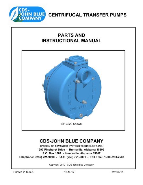
CENTRIFUGAL TRANSFER PUMPS<br />
PARTS AND<br />
INSTRUCTIONAL MANUAL<br />
SP-3220 Shown<br />
<strong>CDS</strong>-JOHN BLUE COMPANY<br />
DIVISION OF ADVANCED SYSTEMS TECHNOLOGY, INC.<br />
290 Pinehurst Drive - Huntsville, Alabama 35806<br />
P.O. Box 1607 - Huntsville, Alabama 35807<br />
Telephone: (256) 721-9090 - FAX: (256) 721-9091 - Toll Free: 1-800-253-2583<br />
Copyright 2010 <strong>CDS</strong>-<strong>John</strong> <strong>Blue</strong> Company<br />
Printed in U.S.A. 12-M-17 Rev 06/11
SAFETY PRECAUTIONS<br />
• Equipment should be operated only by responsible people.<br />
• A careful operator is the best insurance against an accident.<br />
• Fill system with WATER first <strong>and</strong> check output.<br />
• Check all valves, fittings, hose clamps, etc. for wear / leaks before admitting process fluid<br />
to the system.<br />
• Replace hoses when worn, cracked, or if leaking.<br />
WARNING: USE OF THIS PRODUCT FOR ANY PURPOSES OTHER THAN ITS ORIGINAL INTENT, ABUSE<br />
OF THE PRODUCT, AND/OR MODIFICATION TO THE ORIGINAL PRODUCT IS STRICTLY PROHIBITED BY<br />
<strong>CDS</strong>-JOHN BLUE COMPANY. <strong>CDS</strong>-JOHN BLUE COMPANY RESERVES THE RIGHT TO DENY<br />
WARRANTY OR LIABILITY CLAIMS IN ANY/ALL SITUATIONS INVOLVING MISUSE, ABUSE OR<br />
MODIFICATION.<br />
THE ORIGINAL INTENT OF THIS PRODUCT DOES NOT INCLUDE USE WHERE THE MAXIMUM<br />
ALLOWED SPEED, PRESSURE, OR TEMPERATURE IS EXCEEDED, AND IT DOES NOT INCLUDE<br />
APPLICATIONS UTILIZING FLUIDS THAT ARE NOT COMPATIBLE WITH THE PRODUCT’S COMPONENT<br />
MATERIALS. DO NOT USE THIS PRODUCT WITH FLAMMABLE OR COMBUSTIBLE FLUIDS SUCH AS<br />
GASOLINE, KEROSENE, DIESEL, ETC…, AND DO NOT USE IN EXPLOSIVE ATMOSPHERES. FAILURE<br />
TO FOLLOW THIS NOTICE MAY RESULT IN SERIOUS INJURY AND/OR PROPERTY DAMAGE AND WILL<br />
VOID THE PRODUCT WARRANTY. IF IN DOUBT ABOUT YOUR APPLICATION, CONTACT YOUR<br />
STOCKING DEALER OR THE <strong>CDS</strong>-JOHN BLUE TECHNICAL STAFF AT 1-800-253-2583.<br />
To The Owner<br />
This manual has been prepared <strong>and</strong> illustrated to assist you in the maintenance of your <strong>CDS</strong> – JOHN BLUE<br />
PUMP. Enter your serial number <strong>and</strong> the date of the purchase in the space provided below for future reference<br />
in service information or for ordering <strong>parts</strong>. Because our engineering department is constantly improving<br />
products, we reserve the right to make design <strong>and</strong> specification changes without notice.<br />
Model Number: ________________ Serial Number: ________________ Purchase Date: ________________<br />
3
TABLE OF CONTENTS<br />
Safety Precautions ………………………………………………………………………………………………… 3<br />
Note to the Owner …………………………………………………………………………………………………. 3<br />
Table of Contents …………………………………………………………………………………………….……. 4<br />
Pump Specifications <strong>and</strong> Flow Curves ……..…………………………………………………………….……… 5<br />
Pump Model List….…………………………………………………………………………….…………………… 6<br />
Installation …………………………………………………………………………………………………..……… 7<br />
Maintenance ……………………………………………………………………………..……………………..….. 8<br />
Storage …………………………………………………………………………..…………………………………. 8<br />
Repair …………………………………………………………….……………..………………………………...… 9<br />
Hydraulic System Information ………………………………………………….………………………..…...…… 11<br />
Parts Listings<br />
Straight 2” ………..………………………………………………………………………………....…….. 13<br />
Straight 3” ………..………………………………………………………………………………....…….. 14<br />
Self-Priming 2” ….………………………………………………………………………………....…….. 15<br />
Self-Priming 3” ….………………………………………………………………………………....…….. 16<br />
S-3325-P Pedestal ………………………………………………………………………………....…….. 17<br />
Close-Coupled Pedestals …….…………………………………………………………………....…….. 18<br />
Electric Motor <strong>and</strong> Gas Engine Models ………………....……………………………………....…….. 19<br />
Hydraulic Motor Drive Kits ….……………..……………………………………………………....…….. 20<br />
Dimensional Information …...…………..…..……………………………………………………………....…….. 21<br />
Troubleshooting ….……………………..…..……………………………………………………………....…….. 22<br />
Notes ……………….……………………..…..……………………………………………………………....…….. 23<br />
Warranty ……………………………………………………………………………………………………....……. 24<br />
4
PUMP SPECIFICATIONS<br />
SP-3320 &<br />
(Values are for Water) S-3220 S-3320 SP-3220 SP-3325-P S-3325-P<br />
Max. Attainable Flow: 197 GPM 365 GPM 152 GPM 308 GPM 463 GPM<br />
Max. Attainable Pressure: 39 PSI 60 PSI 42 PSI 65 PSI 99 PSI<br />
Max. Operating Speed: 3500 RPM 3500 RPM 3500 RPM 3500 RPM 4500 RPM<br />
Max. Required Horsepower: 5 Hp 10 Hp 5 Hp 10 Hp 16.5 Hp<br />
Rotation (from input side): CW CW CW CW CW<br />
Plumbing Size: 2” FNPT 3” FNPT 2” FNPT 3” FNPT 3” FNPT<br />
Housing Configuration: Straight Straight Self-Priming Self-Priming Straight<br />
5
PUMP MODEL LIST<br />
The VAC-U-SEAL line of <strong>CDS</strong>-<strong>John</strong> <strong>Blue</strong> Centrifugal Transfer Pumps is very complete <strong>and</strong> versatile in<br />
that many combinations can be assembled from available components. Due to the complex nature of the<br />
system, it is of great importance that you know the exact model of your pump, its size, straight or self priming,<br />
<strong>and</strong> material of construction when obtaining service <strong>parts</strong> or technical support. The model list <strong>and</strong> figures<br />
below will be helpful in determining the correct nomenclature for your pump.<br />
Pumps with Adapters for Gasoline Engines Pumps with Adapters for Electric Motors<br />
S‐3220 2" NPT Straight Pump S‐3220‐E 2" NPT Straight Pump<br />
S‐3320 3" NPT Straight Pump SP‐3220‐E 2" NPT Self‐Priming Pump<br />
S‐3320‐BS ** 3" NPT Straight Pump (BS) S‐3320‐E 3" NPT Straight Pump<br />
SP‐3220 2" NPT Self‐Priming Pump SP‐3320‐E 3" NPT Self‐Priming Pump<br />
SP‐3320 3" NPT Self‐Priming Pump<br />
SP‐3320‐BS ** 3" NPT Self‐Priming Pump (BS) Pumps Coupled to Gasoline Engines<br />
** BS <strong>pumps</strong> accept a 1" diameter engine shaft S‐3220‐G5H 2" NPT Straight Pump, 5Hp Honda, w/Base<br />
Note: Adding “C” suffix denotes silicon carbide seals S‐3220‐G5LCT 2” NPT Straight Pump, 5.5hp LCT, w/ Base<br />
Note: Adding “FLG” suffix denotes flanged inlet <strong>and</strong><br />
outlet adapters<br />
SP‐3220‐G5H 2" NPT Self‐Priming, 5Hp Honda, w/Base<br />
SP‐3220‐G5LCT 2” NPT Self‐Priming, 5.5Hp LCT, w/ Base<br />
SP‐3320‐G13H 3" NPT Self‐Priming, 13Hp Honda, Elec. Start, w/Base<br />
SP‐3320‐G13LCT 3” NPT Self‐Priming, 13Hp LCT, Elec. Start, w/Base<br />
Pumps Coupled to Electric Motors Pumps with Hydraulic Drive<br />
S‐3220‐E5D1 2" NPT Straight Pump, 5 Hp, 1 Phase S‐3220‐PH 2" NPT Straight Pump with Hyd. Drive, w/Base<br />
S‐3220‐E5D3 2" NPT Straight Pump, 5 Hp, 3 Phase SP‐3220‐PH 2" NPT Self‐Priming Pump with Hyd. Drive, w/Base<br />
S‐3220‐E5T3 2" NPT Straight Pump, 5 Hp, 3 Phase, TEFC S‐3325‐PH 3” NPT Straight Pump with Hyd. Drive – 25 GPM<br />
S‐3320‐E10T‐1 3" NPT Straight Pump, 10 Hp, 1 Phase, TEFC SP‐3325‐PH 3” NPT Self‐Priming Pump w/Hyd. Drive– 25 GPM<br />
S‐3320‐E10TB‐1 3" NPT Straight Pump, 10 Hp, 1 Phase, TEFC, w/Base S‐3325‐PHL 3” NPT Straight Pump w/LF Hyd. Drive – 14 GPM<br />
S‐3320‐E10T 3" NPT Straight Pump, 10 Hp, 3 Phase, TEFC SP‐3325‐PHL 3” NPT Self‐Priming Pump w/LF Hyd. Drive– 14 GPM<br />
S‐3320‐E15T 3" NPT Straight Pump, 15 Hp, 3 Phase, TEFC<br />
SP‐3220‐E5D1B 2" NPT Straight Pump, 5 Hp, 1 Phase, with Base Pumps with Pedestals<br />
SP‐3220‐E5T1B 2" NPT Straight Pump, 5 Hp, 1 Phase, with Base, TEFC S‐3220‐P 2" NPT Straight Pump with Pedestal<br />
SP‐3220‐E5D3B 2" NPT Straight Pump, 5 Hp, 3 Phase, with Base SP‐3220‐P 2" NPT Self‐Priming Pump with Pedestal<br />
SP‐3220‐E5T3B 2" NPT Straight Pump, 5 Hp, 3 Phase, TEFC, with Base S‐3320‐P 3" NPT Straight Pump with Pedestal<br />
SP‐3320‐E10TB‐1 3" NPT Straight Pump, 10 Hp, 1 Phase, TEFC, with Base S‐3325‐P 3" NPT Straight Pump for Truck mounting<br />
SP‐3320‐E10TB 3" NPT Straight Pump, 10 Hp, 3 Phase, TEFC, with Base SP‐3320‐P 3" NPT Self‐Priming Pump with Pedestal<br />
SP‐3320‐E15TB 3" NPT Straight Pump, 15 Hp, 3 Phase, TEFC, with Base SP‐3325‐P 3" NPT Self‐Priming Pump for Truck mounting<br />
Straight<br />
Self-Priming –<br />
Flanged Fittings<br />
6<br />
Close Coupled Gas Engine<br />
Close Coupled Electric Motor Truck Pump Pedestal – Straight Housing
INSTALLATION<br />
MOUNTING Rotation Direction<br />
• The pump should be installed in a clean, dry, <strong>and</strong> well ventilated<br />
area – preferably close to the fluid supply tank.<br />
Arrow<br />
• The pump should be mounted so that the sight window is at the<br />
top of the seal reservoir, <strong>and</strong> it may be moved to one of the other<br />
ports on the seal reservoir if necessary.<br />
• If the seal reservoir fluid is drained for any reason, a 50/50 mixture<br />
of ethylene glycol antifreeze <strong>and</strong> water should be used to replace it,<br />
filled to half-way up the window.<br />
• Be sure to note the direction arrow cast into the pump body, <strong>and</strong><br />
double check your power source’s rotation direction.<br />
Sight Window<br />
• For close-coupling to a motor, engine, or pedestal, the following must be observed:<br />
o Vac-U-Seal <strong>pumps</strong> must NEVER be used on engines or motors with plain bearings – ONLY use<br />
engines or motors equipped with ball bearings. Plain bearings allow the shaft to float or slide<br />
axially. The engine/motor/pedestal shaft is what supports the impeller in the housing, <strong>and</strong> it<br />
must be rigidly supported <strong>and</strong> constrained.<br />
o When sliding the shaft in to the pump shaft, pre-lube the shaft with a light oil <strong>and</strong> clean the shaft<br />
of all debris <strong>and</strong> burrs. NEVER FORCE THE PUMP ONTO THE SHAFT. It should slide on<br />
easily – investigate any interference.<br />
o When clamping the pump shaft onto the engine/motor/<br />
Pedestal shaft, ensure that the split lines of the coupling<br />
are spaced evenly between the slits in the pump shaft.<br />
o Tighten the bolts of the clamp evenly so that the gaps<br />
on each side are equal.<br />
Place clamp split line<br />
between slits in shaft<br />
PIPING<br />
• Vac-U-Seal <strong>pumps</strong> are not designed to support piping. If piping is used, it should be supported<br />
independently of the pump <strong>and</strong> connected to the pump with flexible members such as hose.<br />
• It is recommended that new clean pipe be used at installation, <strong>and</strong> be of the same size as the pump ports.<br />
For long distances, the pipe size may need to be increased.<br />
• The suction pipe should always be sloped upward to avoid creating air pockets in the line.<br />
ELECTRICAL<br />
• For electric motors, a licensed electrician must be used to wire the pump/motor assembly. The wire <strong>and</strong><br />
fuses should be sized by the licensed electrician based on the motor tag data <strong>and</strong> the length of wire run.<br />
• Do not use the pump/motor assembly in explosive atmospheres – ensure adequate ventilation.<br />
7
GAS ENGINES<br />
• For gas engines with electric start, use 6 ga cable to connect both the positive terminal of the battery to the<br />
stud on the starter solenoid, <strong>and</strong> the negative terminal of the battery to an engine mounting bolt or a good<br />
grounding point on the frame. The length of cable should be kept to a minimum, preferably 3ft or less.<br />
• The battery used should be 12v – 18Ah or larger, <strong>and</strong> it must be securely mounted to the frame.<br />
• Coat terminals <strong>and</strong> cable ends with grease.<br />
• Do not use the pump/engine assembly in explosive atmospheres – ensure adequate ventilation.<br />
MAINTENANCE<br />
• Inspect the seal reservoir fluid level using the sight window – it should be above the middle of the window.<br />
• If dirty, replace the fluid by draining <strong>and</strong> replacing with a 50/50 mixture of ethylene glycol antifreeze <strong>and</strong><br />
water. The recommended service interval for this fluid is 100 hours.<br />
• If the fluid in the seal reservoir becomes cloudy or loses fluid after use, the impeller side seal is leaking <strong>and</strong><br />
should be replaced.<br />
• Inspect the pump frequently for any leaks from the housing gaskets or shaft seal.<br />
STORAGE<br />
** IMPORTANT – KEEP AIR OUT OF THE PUMP AND KEEP FROM FREEZING**<br />
• Keep air out of the pump! This is the only way to prevent corrosion. Even for short periods of storage, the<br />
entrance of air into the pump causes RAPID <strong>and</strong> SEVERE CORROSION. Freezing temperatures can<br />
cause the fluid or water to freeze internally to the pump, which can cause severe damage to castings.<br />
• To prevent excessive corrosion of the pump’s cast iron components:<br />
o Flush pump thoroughly with 5 to 10 gallons of a solution that will neutralize the liquid last<br />
pumped (refer to that manufacturer’s instructions). Fill with clean water <strong>and</strong> DO NOT DRAIN.<br />
Keep pump sealed to exclude air by placing plugs in the suction <strong>and</strong> discharge lines to keep<br />
pump full. For long-term storage (more than 2 weeks), use straight RV-antifreeze (which has a<br />
corrosion inhibitor) to fill the pump after flushing.<br />
• To protect pump from freezing:<br />
o Flush pump per instructions above <strong>and</strong> IMMEDIATELY fill pump with straight RV-antifreeze.<br />
Place plugs in the suction <strong>and</strong> discharge lines to keep pump full <strong>and</strong> exclude air.<br />
8
REPAIR<br />
SEAL REPLACEMENT<br />
* Be sure to order the correct seal for your pump: Ceramic (white seat sealing surfaces) or Carbide (gray)<br />
1.) Loosen the shaft clamp, <strong>and</strong> unbolt the pump adapter from the engine/motor/pedestal. Penetrating oil<br />
should be allowed to soak between pump shaft <strong>and</strong> the driving shaft if it is stuck.<br />
2.) Carefully remove the pump from the engine/motor/pedestal by pulling it straight off of the shaft. Do not<br />
pry the pump back <strong>and</strong> forth, as it may bend the tabs of the pump shaft.<br />
3.) Disassemble the pump by draining the seal reservoir fluid, <strong>and</strong> then removing the motor/engine adapter<br />
<strong>and</strong> the reservoir housing.<br />
4.) Remove the seal seats from the pump castings, <strong>and</strong> carefully clean the counterbores where they fit.<br />
5.) When re-installing new seal seats, coat the rubber o.d. with a quality pipe compound like Rector Seal,<br />
<strong>and</strong> press the seal seat fully into the casting counterbores. The compound will lubricate the seat for<br />
installation <strong>and</strong> prevent corrosion under the seat.<br />
6.) Using a small hammer <strong>and</strong> a plastic tube or block on the seal seat, you may lightly tap the seats into the<br />
counterbores to make sure they are bottomed out fully.<br />
7.) Before re-assembly, make sure the ceramic faces (where the rotary seal will touch) are clean.<br />
8.) Thoroughly clean the shaft <strong>and</strong> lightly lubricate it with oil or grease before installing the shaft seals <strong>and</strong><br />
spring onto the shaft.<br />
9.) Assemble the pump using new rubber gaskets between the casting components <strong>and</strong> replace impeller<br />
wear rings as necessary. Note: Wear rings fit very tightly <strong>and</strong> must be stretched by h<strong>and</strong> before being<br />
rolled onto the <strong>parts</strong>.<br />
10.) Re-install the anti-freeze/water mixture as described in the Maintenance section.<br />
Housing rubber<br />
gasket (typ. 2)<br />
Counterbore for seal<br />
seat (typ. 2)<br />
9<br />
Install wear rings on<br />
these diameters<br />
Impeller wear<br />
rings (typ. 2)
IMPELLER REPLACEMENT (refer to the appropriate <strong>parts</strong> listing for your model):<br />
• 2” <strong>pumps</strong>: Remove plumbing from the pump, <strong>and</strong> then the (4) nuts holding the pump housing to the seal<br />
reservoir on a straight pump, or (6) nuts holding the housing to the housing back cover on the self-priming.<br />
Remove housing. Hold the pump shaft stationary, <strong>and</strong> first unscrew the impeller locknut, then the impeller<br />
itself (both have right-h<strong>and</strong> threads) using a large screwdriver inserted in the vanes.<br />
o Be sure to use new rubber gaskets when re-assembling the pump.<br />
o It is also recommended to replace the two Teflon wear rings on the impeller<br />
• 3” self-priming <strong>pumps</strong>: Use the same instructions as above, except that there are (12) nuts holding the<br />
pump housing to the housing back cover.<br />
• 3” straight <strong>pumps</strong> (including the S-3325-P Truck Pump): Because the studs attaching the pump housing<br />
extend through the seal reservoir, the reservoir must be drained before the (4) nuts are removed <strong>and</strong> the<br />
pump pulled apart. Replace all rubber gaskets when re-assembling. Fill the reservoir per the instructions<br />
given in the Maintenance section.<br />
PEDESTAL BEARING/SHAFT REPLACEMENT (refer to the appropriate <strong>parts</strong> listing for your model):<br />
• 2” <strong>pumps</strong>: The shaft <strong>and</strong> bearings of the 2” pedestal must be replaced as an assembly, <strong>and</strong> it must be<br />
pressed out through the pump side of the pedestal.<br />
• 3” <strong>pumps</strong>: The shaft or bearings may be replaced independently of each other. The bearing cap must be<br />
removed after removing the (3) bolts retaining it. The shaft <strong>and</strong> bearings may now be pressed out through<br />
the pump side of the housing.<br />
• S/SP-3325-P Truck Pumps: The pump must be disassembled (see impeller removal instructions above)<br />
prior to replacing the bearings <strong>and</strong>/or shaft.<br />
10
HYDRAULIC CIRCUIT INFORMATION<br />
INSTALLATION INFORMATION<br />
• Hydraulically driven <strong>pumps</strong> require a pedestal assembly to accept the motor adapter. If you are converting<br />
an existing pump without a pedestal, one will have to be obtained.<br />
• The hydraulic motor is attached to the pedestal using a motor adapter <strong>and</strong> a flexible coupling.<br />
• The hydraulic motor high pressure inlet port is marked “IN”, “P”, or “PR” (pressure), <strong>and</strong> the outlet or return<br />
is usually marked “OUT” or “TK” (tank).<br />
• The hydraulic motor requirements for driving 2” <strong>pumps</strong> are: 6 GPM min, 1000 psi min, CCW Rot.<br />
o Hydraulic drive kit: 110345 (contains 110346-01 motor, S-3601 adapter, <strong>and</strong> hardware)<br />
o Kit installs on the S-3342 2” pump pedestal<br />
• The hydraulic motor requirements for driving 3” <strong>pumps</strong> depend on which motor is selected:<br />
o Hydraulic drive kit: 115910-91 (contains 107030-02 motor, 107016-02 adapter, <strong>and</strong> hardware)<br />
25 GPM min, 1500 psi min, CCW Rot.<br />
o Hydraulic drive kit: 115910-91L (contains 107030-03 motor, 107016-02 adapter, <strong>and</strong> hardware)<br />
14 GPM min, 1500 psi min, CCW Rot.<br />
o Both kits install onto the S/SP-3325-P 3” truck pump pedestal<br />
CHECK VALVE<br />
• The hydraulic motor must be equipped with an in-line check valve at its outlet to protect the motor seals in<br />
the event the return hose is pressurized. It is recommended that a low pressure oil return is used.<br />
TRACTOR CONTROL VALVE<br />
• The tractor valve lever for any of the types of tractor hydraulic systems (listed below) must be locked in the<br />
open position for operation of the pump.<br />
• If the tractor control valve is used to start <strong>and</strong> stop the pump on a closed-center hydraulic system, it is<br />
possible to create damaging pressure spikes because the valve can block the return port while the motor is<br />
running (creating a pressure spike in that line from the motor/pump momentum). Alternatives to prevent<br />
pressures spikes are adding an in-line start-stop valve, or setting the tractor system to “float” when turning<br />
off the flow to the motor.<br />
11
TRACTOR HYDRAULIC SYSTEM TYPES<br />
• There are three types of tractor hydraulic systems available today:<br />
OPEN CENTER SYSTEM<br />
o Open center systems utilize a constant flow pump<br />
o This requires the use of an in-line by-pass valve to control the speed of the hydraulic motor.<br />
(Note: The 2” pump motor (110346-01) has a built-in bypass valve, <strong>and</strong> it is adjusted using the<br />
slotted shaft <strong>and</strong> locknut on the side of the motor.)<br />
o If a large amount of oil is bypassed when running the pump motor, a significant amount of heat<br />
can be generated in the oil, which could damage the tractor’s hydraulic system.<br />
o Auxiliary cooling or reducing the engine speed may be necessary to avoid damage.<br />
CLOSED CENTER PRESSURE COMPENSATED SYSTEM<br />
o Closed center pressure compensated systems utilize a variable stroke pump that increases the<br />
flow rate until a certain pressure is reached, at which point the flow rate remains constant.<br />
o In order to operate the pump hydraulic motor at the proper speed, pressure must be built-up<br />
against the pump to restrict its rate of flow, so a restriction must be added before the motor inlet.<br />
o This may be accomplished in two ways: with a needle valve in-line before the motor inlet port,<br />
or with an in-line orifice before the motor inlet port. It is important to install the orifice before<br />
the inlet port only, because damage to the motor may result if it is installed in the outlet.<br />
o The speed of the pump may then be adjusted with the tractor’s flow control valve.<br />
o Do not use a by-pass valve with a pressure compensated closed center system.<br />
o When turning off flow to the motor using the tractor control valve, the controls must be set to the<br />
float position to prevent pressure spikes.<br />
CLOSED CENTER LOAD SENSING SYSTEM<br />
o Closed center load sensing systems are similar to the pressure compensated systems, except<br />
that they have flow compensation too, which results in less heat generation <strong>and</strong> higher<br />
efficiency.<br />
o The speed of the pump will be adjusted with the tractor’s flow control valve.<br />
o Do not use a by-pass valve or an orifice with a load sensing closed center system.<br />
o When turning off flow to the motor using the tractor control valve, the controls must be set to the<br />
float position to prevent pressure spikes.<br />
12
PARTS LISTING: S-3220 (2” STRAIGHT)<br />
13
PARTS LISTING: S-3320 (3” STRAIGHT)<br />
14
PARTS LISTING: SP-3220 (2” SELF-PRIMING)<br />
15
PARTS LISTING: SP-3320 (3” SELF-PRIMING)<br />
16
PARTS LISTING: S-3325-P TRUCK PUMP PEDESTAL<br />
(USED WITH 3” STRAIGHT OR SELF-PRIMING PUMPS)<br />
17
PARTS LISTING: CLOSE-COUPLED PEDESTALS<br />
2” PUMP PEDESTAL<br />
S-3342<br />
3” PUMP PEDESTAL<br />
S-3334<br />
18
PARTS LISTING: ELECTRIC MOTOR & GAS ENGINE MODELS<br />
(A) 2” PUMP W/GAS OR ELEC. (B) 3” PUMP W/10HP ELEC.<br />
(C) 3” PUMP W/15HP ELEC.<br />
(B) 3” PUMP W/13HP GAS<br />
MODEL PART # DESCRIPTION<br />
A S‐3321 BASE KIT ‐ 2" PUMP FOR ELEC. MOTOR OR GAS ENGINE<br />
(INCLUDES S‐3595, S‐3596, MOUNTING HARDWARE)<br />
S‐3595 BASE ‐ 2" PUMP W/ELEC. MOTOR OR GAS ENGINE<br />
S‐3596 PUMP HANDLE ‐ USED WITH 2" SP PUMP<br />
C‐5962 / C‐5960 5HP ELECTRIC MOTOR, DRIP‐PROOF (3PH / 1PH)<br />
C‐5963 / C‐5961 5HP ELECTRIC MOTOR, TEFC (3PH / 1PH)<br />
113798‐01 5.5 HP HONDA GAS ENGINE<br />
116056‐01 5.5 HP LCT GAS ENGINE<br />
B S‐3336 BASE KIT ‐ 3" PUMP FOR 10 HP ELECTRIC MOTOR OR GAS ENGINE<br />
(INCLUDES 108130‐91, 108131‐01, MOUNTING HARDWARE)<br />
108130‐91 BASE ‐ 3" PUMP W/ELEC. MOTOR OR GAS ENGINE<br />
108131‐01 SUPPORT PLATE ‐ USED FOR 3" SP PUMP W/10 HP MOTOR & GAS<br />
C‐517 / 115277‐01 10HP ELECTRIC MOTOR, TEFC (3PH / 1PH)<br />
115457‐01 13HP HONDA GAS ENGINE<br />
116057‐01 13HP LCT GAS ENGINE<br />
C 108129 BASE KIT ‐ 3" PUMP FOR 15 HP ELECTRIC MOTOR<br />
(INCLUDES 108130‐91, 108127‐01, MOUNTING HARDWARE)<br />
108130‐91 BASE ‐ 3" PUMP W/ELEC. MOTOR OR GAS ENGINE<br />
108127‐01 SUPPORT PLATE ‐ USED FOR 3" SP PUMP W/15 HP MOTOR<br />
108128 15HP ELECTRIC MOTOR, TEFC, 3PH<br />
19
PARTS LISTING: HYDRAULIC MOTOR DRIVE KITS<br />
2” PUMP HYDRAULIC<br />
MOTOR DRIVE KIT<br />
110345<br />
Required<br />
Rotation<br />
3” PUMP HYDRAULIC<br />
MOTOR DRIVE KITS<br />
115910-91 - 25 GPM<br />
15910-91L - 14 GPM<br />
Required<br />
Rotation<br />
Bypass valve adjustment<br />
shaft on opposite side<br />
20<br />
HYDRAULIC MOTOR DETAILS:<br />
COUNTER-CLOCKWISE (CCW) ROTATION<br />
4-BOLT 4F17 FLANGE<br />
3400 RPM MAX 1000 PSI MAX CONT.<br />
0.00149 GAL/REV<br />
3/8” NPT INLET AND OUTLET PORTS<br />
7/16” DIAMETER x 1.13” LONG SHAFT<br />
APPROX. 5 GPM REQUIRED AT 3400 RPM<br />
HYDRAULIC MOTOR DETAILS:<br />
COUNTER-CLOCKWISE (CCW) ROTATION<br />
SAE “A” 2-BOLT FLANGE<br />
3400 RPM MAX 3500 PSI MAX CONT.<br />
#16 O-RING INLET AND OUTLET PORTS<br />
3/4” DIAMETER x 1.94” LONG SHAFT<br />
“107030-02” STD. MOTOR: 0.0072 GAL/REV<br />
(APPROX. 25 GPM REQUIRED AT 3400 RPM)<br />
“107030-03” LOW FLOW MOTOR: 0.0038 GAL/REV<br />
(APPROX. 14 GPM REQUIRED AT 3400 RPM)
DIMENSIONAL INFORMATION<br />
S-3220 (2” NPT PORTS)<br />
SP-3220 (2” NPT PORTS)<br />
2” PEDESTAL<br />
2” PUMP BASE DETAIL<br />
3” PEDESTAL<br />
21<br />
S-3320 (3” NPT PORTS)<br />
SP-3320 (3” NPT PORTS)<br />
SP-3325-P (3” NPT PORTS)<br />
3” PUMP BASE DETAIL
TROUBLE SHOOTING<br />
ISSUE PROBABLE CAUSE<br />
Pump makes rattling noise while running Cavitation or pump starvation (suction lift is too high or<br />
the inlet line is too restrictive)<br />
Reduced pump output or pressure Clogged impeller or inlet piping (including strainer)<br />
Leaks in suction line or at inlet gasket<br />
Collapsed suction line<br />
Trapped air in sections of suction line<br />
Suction lift is too great<br />
Discharge lift is too great<br />
Worn or damaged <strong>parts</strong> (impeller or casing)<br />
Pump fails to prime or slow prime Leaks in suction line or at inlet gasket<br />
Suction lift is too great<br />
Collapsed suction line<br />
Not enough water in casing to prime pump (self-priming)<br />
Seal reservoir fluid changes level Leak at the input shaft seal if level is low<br />
Pump makes screeching or metal on metal<br />
noises<br />
Leak at the impeller side seal if level is high<br />
Improper installation on motor, engine, or pedestal shaft<br />
The shaft (<strong>and</strong> impeller) have been forced into the pump<br />
<strong>and</strong> against the volute<br />
22
NOTES<br />
23
LIMITED WARRANTY<br />
THIS WARRANTY IS IN LIEU OF ALL OTHER WRITTEN OR EXPRESS WARRANTIES AND<br />
REPRESENTATIONS. ANY IMPLIED WARRANTIES INCLUDING MERCHANTABILITY OR FITNESS FOR ANY<br />
PARTICULAR PURPOSE ARE EXPRESSLY LIMITED TO THIS WRITTEN WARRANTY. <strong>CDS</strong>-JOHN BLUE<br />
COMPANY SHALL NOT BE LIABLE FOR CONSEQUENTIAL DAMAGES.<br />
Use of this product for any purpose other than its original intent, abuse of the product, <strong>and</strong>/or any modification to<br />
the original product is strictly prohibited by the manufacturer, <strong>CDS</strong>-<strong>John</strong> <strong>Blue</strong> Company. Any modification to the<br />
product should be approved by <strong>CDS</strong>-<strong>John</strong> <strong>Blue</strong> Company prior to use. <strong>CDS</strong>-<strong>John</strong> <strong>Blue</strong> Company will deny<br />
Warranty claims <strong>and</strong> liability in any situation involving misuse, abuse or modification.<br />
Each new machine or component manufactured by <strong>CDS</strong>-<strong>John</strong> <strong>Blue</strong> Company through original buyer is warranted<br />
by <strong>CDS</strong>-<strong>John</strong> <strong>Blue</strong> Company to buyer <strong>and</strong> to any party or parties to whom buyer may resell, lease or lend the<br />
equipment to be free from defects in material <strong>and</strong> workmanship under normal use <strong>and</strong> service. This obligation of<br />
<strong>CDS</strong>-<strong>John</strong> <strong>Blue</strong> Company under this warranty is limited to the repair or replacement of defective <strong>parts</strong> or<br />
correction of improper workmanship of any <strong>parts</strong> of such equipment which shall within two years from the date of<br />
<strong>CDS</strong>-<strong>John</strong> <strong>Blue</strong>’s original delivery thereof, be returned to <strong>CDS</strong>-<strong>John</strong> <strong>Blue</strong>’s factory, transportation charges prepaid<br />
<strong>and</strong> which <strong>CDS</strong>-<strong>John</strong> <strong>Blue</strong> Company shall determine to its satisfaction upon examination thereof to have been<br />
thus defective. When it is impractical to return the defective <strong>parts</strong> of such equipment to <strong>CDS</strong>-<strong>John</strong> <strong>Blue</strong>’s factory,<br />
then <strong>CDS</strong>-<strong>John</strong> <strong>Blue</strong> shall have no liability for the labor cost involved in repairing or replacing any such <strong>parts</strong> <strong>and</strong><br />
shall be liable solely for supplying the material necessary to replace or repair the defective <strong>parts</strong>, provided that<br />
prior thereto <strong>CDS</strong>-<strong>John</strong> <strong>Blue</strong> Company shall have determined to its satisfaction that any such <strong>parts</strong> are thus<br />
defective.<br />
This warranty shall not apply to any equipment which shall have been repaired or altered outside <strong>CDS</strong>-<strong>John</strong><br />
<strong>Blue</strong>’s factory in any way so as to affect its durability, nor which has been subjected to misuse, abuse, negligence<br />
or accident, or operated in any manner other than in accordance with operating instructions provided by <strong>CDS</strong>-<br />
<strong>John</strong> <strong>Blue</strong> Company. This warranty does not extend to repairs made necessary by the use of inferior or<br />
unsuitable <strong>parts</strong> or accessories, or <strong>parts</strong> or accessories not recommended by <strong>CDS</strong>-<strong>John</strong> <strong>Blue</strong> Company.<br />
<strong>CDS</strong>-<strong>John</strong> <strong>Blue</strong> Company makes no warranties in respect to <strong>parts</strong>, accessories or components not manufactured<br />
by <strong>CDS</strong>-<strong>John</strong> <strong>Blue</strong> Company, same ordinarily being warranted separately by their respective manufacturers.<br />
DIVISION OF ADVANCED SYSTEMS TECHNOLOGIES HUNTSVILLE, AL (256) 721-9090<br />
<strong>CDS</strong>-<strong>John</strong> <strong>Blue</strong> Company<br />
Division of Advanced Systems Technology<br />
290 Pinehurst Dr. Huntsville AL 35806<br />
PO Box 1607 Huntsville AL 35807<br />
Telephone: (256) 721-9090 - Fax (256)-721-9091 - Toll Free 1-800-253-2583<br />
www.cds-johnblue.com<br />
YOUR LOCAL DEALER<br />
24