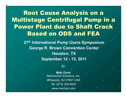
Root Cause Analysis on a Multistage Centrifugal Pump ... - TurboLab
Root Cause Analysis on a Multistage Centrifugal Pump ... - TurboLab
Root Cause Analysis on a Multistage Centrifugal Pump ... - TurboLab

Create successful ePaper yourself
Turn your PDF publications into a flip-book with our unique Google optimized e-Paper software.
241<br />
<str<strong>on</strong>g>Root</str<strong>on</strong>g> <str<strong>on</strong>g>Cause</str<strong>on</strong>g> <str<strong>on</strong>g>Analysis</str<strong>on</strong>g> <strong>on</strong> a<br />
<strong>Multistage</strong> <strong>Centrifugal</strong> <strong>Pump</strong> in a<br />
Power Plant due to Shaft Crack<br />
Based <strong>on</strong> ODS and FEA<br />
27 th Internati<strong>on</strong>al <strong>Pump</strong> Users Symposium<br />
George R. Brown C<strong>on</strong>venti<strong>on</strong> Center<br />
Houst<strong>on</strong>, TX<br />
September 12 - 15, 2011<br />
By:<br />
Maki Onari<br />
Mechanical Soluti<strong>on</strong>s, Inc.<br />
Whippany, NJ 07981 USA<br />
Tel: (973) 326-9920<br />
www.mechsol.com
242<br />
Introducti<strong>on</strong><br />
• Two multistage barrel type pumps for each 1200 MW Unit<br />
were installed in 1986 in a large power plant.<br />
• The 11 stage centrifugal pumps were designated as<br />
<strong>Pump</strong>(s) 1A/B and <strong>Pump</strong>(s) 2A/B. All impellers were<br />
designed with 6 vanes and 8 diffuser vanes.<br />
• The pumps are driven by 600 HP four-pole inducti<strong>on</strong><br />
motors (1,770 rpm or 29.5 Hz) through a gear increaser<br />
(output speed of 4,860 rpm or 81 Hz).<br />
• Rated capacity: 350 GPM and 2,516 ft of TDH<br />
• Normal capacity: 150 GPM (43% BEP).
243<br />
Introducti<strong>on</strong><br />
Barrel Type - 11 stage <strong>Pump</strong><br />
Outline Drawing
244<br />
Introducti<strong>on</strong><br />
Barrel Type - 11 stage <strong>Pump</strong>
245<br />
Background History<br />
• Three pump shaft failures (cracks) have been detected<br />
since <strong>Pump</strong> 1B installati<strong>on</strong> (MTBF=7.7 years).<br />
• In 1989, the first failure took place, but the failure<br />
analysis was not properly documented and the failed<br />
shaft was not saved.<br />
• In 1999, a crack was found at the rear end of the 9 th<br />
stage hub.<br />
• In December 2007, the last failure was discovered<br />
under the 11 th stage impeller hub with evidence of<br />
fretting. A circumferential crack was found at the<br />
keyway with 132 degrees arc. The vibrati<strong>on</strong> level of the<br />
pump had been always c<strong>on</strong>sidered low and adequate.
246<br />
Background History<br />
2007 Failure after<br />
8 years of operati<strong>on</strong>.<br />
Crack detected<br />
under 11 th stage<br />
impeller hub.
247<br />
Background History<br />
2007 Failure after 8 years<br />
of operati<strong>on</strong>.<br />
Crack detected under 11 th<br />
stage impeller hub with the<br />
origin away from the<br />
keyway.
248<br />
Specialized Testing<br />
Experimental Modal <str<strong>on</strong>g>Analysis</str<strong>on</strong>g> (EMA) test to<br />
determine the natural frequencies of the impeller,<br />
pump structure, and the rotor system with their<br />
mode shapes.<br />
M<strong>on</strong>itoring test during transient and steady<br />
operati<strong>on</strong> to m<strong>on</strong>itor the vibrati<strong>on</strong> amplitude and<br />
natural frequencies.<br />
Dynamic pressure transducer data from sucti<strong>on</strong>,<br />
discharge, and balance line.<br />
Operating Deflecti<strong>on</strong> Shape (ODS) testing during<br />
steady operati<strong>on</strong>.
249<br />
11 th Stage Impeller<br />
EMA Testing
250<br />
Vibrati<strong>on</strong> EMA Test<br />
11 th Stage Impeller Modal Impact Test
251<br />
Impeller Model<br />
Vibrati<strong>on</strong> EMA Test<br />
11 th Stage Impeller Modal Impact Test<br />
FRF Wet
252<br />
Vibrati<strong>on</strong> EMA Test<br />
11 th Stage Impeller Modal Impact Test<br />
2 Nodal Diameter / 0 Nodal Circle at 2620 Hz
253<br />
Frequency (Hz)<br />
5000<br />
4000<br />
3000<br />
2000<br />
1000<br />
Vibrati<strong>on</strong> EMA Test<br />
11 th Stage Impeller Modal Impact Test (Wet)<br />
Interference Diagram<br />
11th Stage of 2 1/2 RLIJ Pacific <strong>Pump</strong> (Wet Impeller)<br />
6 Rotating Vanes and 8 Diffuser Vanes<br />
0<br />
0 1 2 3 4 5 6<br />
Nodal Diameter<br />
Interference Diagram<br />
1x VPF<br />
1x Diff VPF<br />
2x Diff VPF<br />
1x V_Dir_Exc<br />
1x V_Dif_Exc<br />
2x V_Dir_Exc<br />
0NC
254<br />
Specialized Field Testing
255<br />
Vibrati<strong>on</strong> M<strong>on</strong>itoring<br />
<strong>Pump</strong> 1B Typical Spectrum OBB in the<br />
Vertical Directi<strong>on</strong><br />
[g]<br />
Autospectrum(Signal 5) - Mark 1 (Magnitude)<br />
Working : ODS2 : Input : FFT Analyzer<br />
1<br />
300m<br />
0.15 in/s peak @ 1x rpm<br />
0.16 in/s peak @ 4x motor rpm<br />
100m<br />
30m<br />
10m<br />
3m<br />
1m<br />
300u<br />
100u<br />
0 100 200 300 400<br />
[Hz]<br />
500 600 700 800<br />
<strong>Pump</strong> Operating at 145 GPM<br />
<strong>Pump</strong> 2B Typical Spectrum OBB in the<br />
Vertical Directi<strong>on</strong><br />
[g]<br />
Autospectrum(Signal 1) - Mark 1 (Magnitude)<br />
Working : 2B Linear Average : Input : FFT Analyzer<br />
1<br />
300m<br />
100m<br />
30m<br />
10m<br />
3m<br />
1m<br />
300u<br />
100u<br />
0.06 in/s peak @ 1x rpm<br />
0.06 in/s peak @ 4x motor rpm<br />
0 100 200 300 400<br />
[Hz]<br />
500 600 700 800<br />
<strong>Pump</strong> Operating at 160 GPM
256<br />
[mil]<br />
Autospectrum(Signal 12) - Mark 1 (Magnitude)<br />
Working : 1B Linear Ave at 100 GPM : Input : FFT Analyzer<br />
1<br />
100m<br />
10m<br />
1m<br />
100u<br />
10u<br />
0.46 mils pk-pk @ ~30 Hz<br />
Vibrati<strong>on</strong> M<strong>on</strong>itoring<br />
<strong>Pump</strong> 1B Axial Proximity Probe FFT<br />
at OBB<br />
0 100 200 300 400<br />
[Hz]<br />
500 600 700 800<br />
<strong>Pump</strong> 1B Axial Proximity Probe Time<br />
Signature at OBB<br />
[mil]<br />
Time(Signal 12) - Mark 1<br />
Working : 1B Linear Ave at 100 GPM : Input : FFT Analyzer<br />
600m<br />
400m<br />
200m<br />
0<br />
- 200m<br />
- 400m<br />
- 600m<br />
29.5 28.3 Hz Hz<br />
0 100m 200m 300m 400m 500m<br />
[s]<br />
600m 700m 800m 900m
257<br />
[mil]<br />
[mil] Autospectrum(Signal 12) - Mark 1 (Magnitude)<br />
Working : 2B Linear Average : Input : FFT Analyzer<br />
300m<br />
100m<br />
30m<br />
10m<br />
3m<br />
1m<br />
300u<br />
100u<br />
0.4 mils pk-pk @ 81 Hz<br />
Vibrati<strong>on</strong> M<strong>on</strong>itoring<br />
<strong>Pump</strong> 2B Axial Proximity Probe FFT<br />
at OBB<br />
0.04 mils pk-pk @ ~30 Hz<br />
0 100 200 300 400<br />
[Hz]<br />
[Hz]<br />
500 600 700 800<br />
<strong>Pump</strong> 2B Axial Proximity Probe<br />
Time Signature at OBB<br />
[mil]<br />
[mil] Time(Signal 12) - Input<br />
Working : Input : Input : FFT Analyzer<br />
600m<br />
400m<br />
200m<br />
0<br />
- 200m<br />
- 400m<br />
- 600m<br />
81 Hz<br />
0 40m 80m 120m 160m 200m 240m 280m 320m 360m 400m 440m 480m<br />
[s]<br />
[s]
258<br />
<strong>Pump</strong> Rotor Modal Impact<br />
Testing During Operati<strong>on</strong>
259<br />
Experimental Modal <str<strong>on</strong>g>Analysis</str<strong>on</strong>g><br />
“Bump” Test<br />
<strong>Pump</strong> 1B Axial Proximity Probe FRF<br />
[mil/lbf]<br />
[mil/lbf] Frequency Resp<strong>on</strong>se(Signal 12,Signal 17) - Mark 1 (Magnitude)<br />
Working : Axial Hits Channel 12 Axial Prox Probe 100 GPM : Input : Enhanced<br />
3m<br />
1m<br />
300u<br />
100u<br />
30u<br />
10u<br />
OBB natural<br />
frequency<br />
29.5 Hz (1x motor speed)<br />
121.2 Hz<br />
0 100 200 300 400 500 600 700 800<br />
[Hz]<br />
[Hz]<br />
[mil/lbf] [mil/lbf]<br />
Frequency Resp<strong>on</strong>se(Signal 12,Signal 17) - Input (Magnitude)<br />
Working : Input : Input : Enhanced<br />
10m<br />
300u<br />
100u<br />
<strong>Pump</strong> operating at 160 GPM<br />
3m<br />
1m<br />
30u<br />
10u<br />
<strong>Pump</strong> 2B Axial Proximity Probe FRF<br />
OBB natural<br />
frequency frequency<br />
81 Hz (1x pump speed)<br />
118.2 Hz (4x motor speed)<br />
0 100 200 300 400<br />
[Hz]<br />
[Hz]<br />
500 600 700 800
260<br />
Operating Deflecti<strong>on</strong> Shape<br />
(ODS)
261<br />
Operating Deflecti<strong>on</strong> Shape<br />
• Natural excitati<strong>on</strong><br />
signature of the pump<br />
train structure.<br />
• Over 700 vibrati<strong>on</strong><br />
measurements.<br />
• Data base of amplitude vs.<br />
frequency and phase<br />
angle.<br />
• 3-D CAD model assigning<br />
moti<strong>on</strong> to each individual<br />
vibrati<strong>on</strong> data point.<br />
• Create animati<strong>on</strong>s of the<br />
pump
262<br />
Operating Deflecti<strong>on</strong> Shape<br />
<strong>Pump</strong> 1B ODS @ 29.9 Hz
263<br />
Operating Deflecti<strong>on</strong> Shape<br />
<strong>Pump</strong> 1B ODS @ 81 Hz
264<br />
Operating Deflecti<strong>on</strong> Shape<br />
<strong>Pump</strong> 2B ODS @ 29.9 Hz
265<br />
Operating Deflecti<strong>on</strong> Shape<br />
<strong>Pump</strong> 2B ODS @ 81 Hz
266<br />
Finite Element <str<strong>on</strong>g>Analysis</str<strong>on</strong>g><br />
(FEA)
267<br />
Axi-symmetric Model<br />
and FEA Breakup
268<br />
[mil]<br />
Time(Signal 12) - Mark 1<br />
Working : 1B Linear Ave at 100 GPM : Input : FFT Analyzer<br />
600m<br />
400m<br />
200m<br />
0<br />
- 200m<br />
- 400m<br />
- 600m<br />
Axi-symmetric Model<br />
Impeller Loading<br />
Axial displacement in displacement (mils pk-pk) and accelerati<strong>on</strong> (g’s)<br />
28.3<br />
29.5<br />
Hz<br />
Hz<br />
0 100m 200m 300m 400m 500m<br />
[s]<br />
600m 700m 800m 900m
269<br />
Axi-symmetric Model<br />
Impeller Loading<br />
Load Step 1:<br />
• Initiate and complete the interference fit between the<br />
impeller and the shaft (2 mils diametral interference)<br />
• C<strong>on</strong>strain the outboard end of shaft at the thrust bearing<br />
Load Step 2:<br />
• Ramp up an axially applied pressure of 75 psi load to the<br />
inboard end over 0.0001sec (30 g’s peak accelerati<strong>on</strong>).<br />
Load Step 3:<br />
• Ramp pressure down to a 0 psi over an additi<strong>on</strong>al<br />
0.0001sec.<br />
Load Step 4:<br />
• Run for an additi<strong>on</strong>al 0.001 sec to m<strong>on</strong>itor the traveling of<br />
the acoustic waves and the impeller interface c<strong>on</strong>diti<strong>on</strong>s.
270<br />
Axi-symmetric Model<br />
FEA Results<br />
• Transient dynamic analysis revealed that acoustic wave<br />
propagati<strong>on</strong> past the impellers can result in micromoti<strong>on</strong><br />
at the press fit interfaces.<br />
• An idealized axi-symmetric model of the pump shaft and<br />
the last stage impeller predicted an impeller to shaft<br />
sliding c<strong>on</strong>diti<strong>on</strong>.<br />
• This sliding c<strong>on</strong>diti<strong>on</strong> led to fretting damage and the<br />
crack initiati<strong>on</strong>.
271<br />
Axi-symmetric Model<br />
FEA Results
272<br />
FEA-Based Fracture<br />
Mechanics Approach<br />
• Assume that relative sliding velocity between the<br />
impeller and shaft is equal to the peak axial shaft velocity<br />
measured <strong>on</strong> the end of shaft near the thrust bearing.<br />
• Assume that fretting c<strong>on</strong>diti<strong>on</strong> and asperities <strong>on</strong> shaft<br />
surface cause the impeller to axially lock-up against the<br />
shaft.<br />
• Model the lock-up behavior as an axial impact between<br />
the shaft and impeller in the regi<strong>on</strong> of the assumed 5 mil<br />
crack.<br />
• Using transient dynamic FEA predict the stress<br />
distributi<strong>on</strong> near the crack and calculate the stress<br />
intensity factor.<br />
• Check whether crack propagati<strong>on</strong> can be expected.
273<br />
FEA-Based Fracture<br />
Mechanics Approach<br />
Impact Velocity 31 in/s pk<br />
(15 g’s pk at 29.9Hz)<br />
0.005 inch crack<br />
explicitly modeled
274<br />
FEA-Based Fracture<br />
Mechanics Approach<br />
Double Peak due to<br />
Impeller Flexing and<br />
Spring-back<br />
v<strong>on</strong> Mises<br />
Stress (psi) at<br />
<str<strong>on</strong>g>Root</str<strong>on</strong>g><br />
of Crack<br />
During Impact<br />
Event
275<br />
FEA-Based Fracture<br />
Mechanics Approach<br />
v<strong>on</strong> Mises Stress Distributi<strong>on</strong> (psi) Macro View
276<br />
FEA-Based Fracture<br />
Mechanics Approach<br />
v<strong>on</strong> Mises Stress Distributi<strong>on</strong> (psi) In Vicinity of Crack<br />
Impact Locati<strong>on</strong><br />
Crack <str<strong>on</strong>g>Root</str<strong>on</strong>g><br />
K = ∆ σ π Z<br />
a ( 1 . 1)<br />
ANSYS Calculated Stress Intensity Factor ∆KI = 16.3 ksi√in<br />
∆
277<br />
FEA-Based Fracture<br />
Mechanics Approach<br />
ANSYS Ki Output<br />
Calculate mixed-mode stress intensity factors<br />
• Assume plane strain c<strong>on</strong>diti<strong>on</strong>s.<br />
• Assume a full-crack model (use 5 nodes)<br />
• Extrapolati<strong>on</strong> path is defined by nodes: 2044520,<br />
2044672, 2044683, 2047304, 2047315<br />
• With node 2044520 as the crack-tip node.<br />
• Use material properties for material number 1 with<br />
Ex = 0.29e+08 µxy = 0.30 at temp = 0.00.<br />
Ki = 16315. , Kii = 7826.4 , kiii = 0.0000
278<br />
Implemented Fixes<br />
• A new gear set was installed in the last outage in Fall 2009.<br />
• Both gear couplings were replaced.<br />
• New pump element installed.<br />
• M<strong>on</strong>itoring of pump shaft axial vibrati<strong>on</strong> and gear drive<br />
vibrati<strong>on</strong> adjusted to address imposed duty <strong>on</strong> pump shaft<br />
due to less than smooth mesh of gears.<br />
• Gear set removed mapped.
279<br />
C<strong>on</strong>clusi<strong>on</strong>s<br />
• The root cause of the repetitive cracking of the pump<br />
shaft is due to a fatigue process while the pump shaft is<br />
oscillating axially driven by the gear tooth circumferential<br />
run-out.<br />
• The axial mismatch of the helical gear set (apex) was the<br />
cause of the axial displacement of the pump shaft at the<br />
driver’s operating speed, generating an impulsive<br />
displacement load due to a geometric abnormality of the<br />
gear teeth of the input shaft gear (axial run-out).<br />
• The ODS test performed <strong>on</strong> <strong>Pump</strong> 1B at the running<br />
speed of the motor (30 Hz) indicated high axial moti<strong>on</strong> of<br />
the pump shaft driving the OBB with a vertical rocking<br />
moti<strong>on</strong>. The gearbox moved axially with some phase lag<br />
with respect to the pump shaft and the motor casing.
280<br />
C<strong>on</strong>clusi<strong>on</strong>s<br />
• The vibrati<strong>on</strong> test performed <strong>on</strong> <strong>Pump</strong> 2B did not indicate<br />
any abnormal axial moti<strong>on</strong> of the pump shaft at the<br />
running speed of the motor (0.04 mils pk-pk versus 0.5<br />
mils pk-pk measured <strong>on</strong> <strong>Pump</strong> 1B).<br />
• Traditi<strong>on</strong>al troubleshooting approaches probably would<br />
not have indicated a gear/pump inter-related problem,<br />
and would not have provided such clear visual evidence<br />
for decisi<strong>on</strong> makers.<br />
• ODS / EMA coupled with appropriate analysis is a<br />
powerful troubleshooting tool to facilitate and visually<br />
understand the most difficult vibrati<strong>on</strong> problems in<br />
turbomachinery and pumping systems.
281
282<br />
Thank you<br />
Any Questi<strong>on</strong>s…?