Analysis of Radial-Flow Impellers of Different Configurations.
Analysis of Radial-Flow Impellers of Different Configurations.
Analysis of Radial-Flow Impellers of Different Configurations.

You also want an ePaper? Increase the reach of your titles
YUMPU automatically turns print PDFs into web optimized ePapers that Google loves.
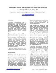
Figure 1: Sectional Drawing <strong>of</strong> a Blower.<br />
Figure 1 illustrates a cross-section <strong>of</strong> the blower<br />
designed. Fluid enters the inlet port at the center<br />
<strong>of</strong> the rotating impeller, or the suction eye. As the<br />
impeller spins in a counter-clockwise direction, it<br />
thrusts the fluid outward radially, causing<br />
centrifugal acceleration. As it does this, it creates<br />
a vacuum in its wake, drawing even more fluid<br />
into the inlet. Centrifugal acceleration creates<br />
energy proportional to the speed <strong>of</strong> the impeller<br />
(Csanady 1981). The faster the impeller rotates,<br />
the faster the fluid movement and the stronger its<br />
force. <strong>Impellers</strong> are the rotating blades that<br />
actually move the fluid. They are connected to the<br />
drive shaft that rotates within the blower casing.<br />
The impeller is designed to impart a whirling or<br />
motion to the air in the blower.<br />
IMPELLER’S BASIC THEORY<br />
As the impeller rotates, it creates vacuum at its<br />
inlet suction side through centrifugal force. In<br />
turn, the impeller creates a positive pressure,<br />
inducing a force <strong>of</strong> air on the discharge side.<br />
Impeller is the most important part <strong>of</strong> the blower<br />
components because <strong>of</strong> the fact that its<br />
performance inadvertently determines the<br />
blower’s performance.<br />
An impeller is essentially a disk shaped structure<br />
with vanes that create the actual suction in a<br />
blower. The impeller is always placed directly<br />
onto the shaft <strong>of</strong> the electric motor so that it spins<br />
at a very high speed. The effects <strong>of</strong> centrifugal<br />
force acting upon the spinning air within the<br />
impeller create the suction. As the impeller<br />
rotates, Von Cube and Steimle (1981) confirms<br />
that the spinning air moves outward away from<br />
the hub, creating a partial vacuum which causes<br />
more air to flow into the impeller.<br />
The most important impeller parameters can be<br />
grouped into three categories:<br />
Geometrical Parameters: Tip diameter, hub<br />
diameter and tip width;<br />
Operating conditions: Inlet total pressure, inlet<br />
total temperature and fluid density;<br />
Performance characteristics: mass flow<br />
parameter, pressure ratio and specific speed.<br />
Technical Performance Data<br />
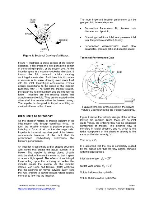
Figure 2: Impeller Cross-Section in the Blower<br />
Volute’s Casing Showing the Velocity Diagrams.<br />
Figure 2 shows the velocity triangle <strong>of</strong> the air flow<br />
leaving the impeller. Since there are no inlet<br />
guide vanes, the entering flow has no tangential<br />
component <strong>of</strong> motion. The entering flow is<br />
therefore in radial direction, and vr1 which is the<br />
radial component <strong>of</strong> the absolute velocity is the<br />
same as the inlet velocity, V1.<br />
That is vr1 = V1.<br />
It is assumed that the flow is completely guided<br />
by the blades and that the flow angles coincide<br />
with the blade angles.<br />
Inlet Vane Angle<br />
Outlet Vane Angle<br />
The Pacific Journal <strong>of</strong> Science and Technology –25–<br />
http://www.akamaiuniversity.us/PJST.htm Volume 13. Number 1. May 2012 (Spring)<br />
1<br />
29<br />
0<br />
0<br />
2 31<br />
Volute Inside radius r1=0.08m<br />
Volute Outside radius r2=0.335m