
You also want an ePaper? Increase the reach of your titles
YUMPU automatically turns print PDFs into web optimized ePapers that Google loves.
FUELS<br />
The discussion in this chapter relates to fossil fuels or chemical fuels<br />
Definition<br />
Fuel is a carbonaceous combustible substance, which on combustion liberates a large<br />
amount of energy in the form of heat.<br />
Classification<br />
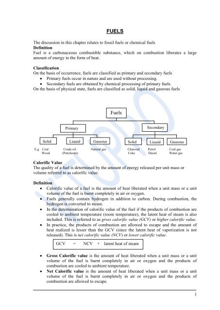
On the basis of occurrence, fuels are classified as primary and secondary fuels<br />
Primary fuels occur in nature and are used without processing.<br />
Secondary fuels are obtained by chemical processing of primary fuels.<br />
On the basis of physical state, fuels are classified as solid, liquid and gaseous fuels<br />
Primary<br />
Fuels<br />
Secondary<br />
Solid Liquid Gaseous Solid Liquid Gaseous<br />
E.g. Coal Crude oil Natural gas Charcoal Petrol Coal gas<br />
Wood (Petroleum) Coke Diesel Water gas<br />
Calorific Value<br />
The quality of a fuel is determined by the amount of energy released per unit mass or<br />
volume referred to as calorific value.<br />
Definition<br />
Calorific value of a fuel is the amount of heat liberated when a unit mass or a unit<br />
volume of the fuel is burnt completely in air or oxygen.<br />
Fuels generally contain hydrogen in addition to carbon. During combustion, the<br />
hydrogen is converted to steam.<br />
In the determination of calorific value of the fuel if the products of combustion are<br />
cooled to ambient temperature (room temperature), the latent heat of steam is also<br />
included. This is referred to as gross calorific value (GCV) or higher calorific value.<br />
In practice, the products of combustion are allowed to escape and the amount of<br />
heat realized is lesser than the GCV (since the latent heat of vaporization is not<br />
released). This is net calorific value (NCV) or lower calorific value.<br />
GCV = NCV + latent heat of steam<br />
Gross Calorific value is the amount of heat liberated when a unit mass or a unit<br />
volume of the fuel is burnt completely in air or oxygen and the products of<br />
combustion are cooled to ambient temperature.<br />
Net Calorific value is the amount of heat liberated when a unit mass or a unit<br />
volume of the fuel is burnt completely in air or oxygen and the products of<br />
combustion are allowed to escape.<br />
1
Determination of Calorific Value of a Solid Fuel Using Bomb Calorimeter<br />
Sample<br />
Stirrer<br />
Construction<br />
The bomb calorimeter (shown in the fig.) consists of an outer cylindrical steel vessel<br />
(bomb) with an airtight screw and an inlet for oxygen.<br />
The bomb has a platinum crucible with a loop of wire. The ends of the wire project<br />
out and can be connected to a source of electric current.<br />
The bomb is immersed in a rectangular vessel (calorimeter) containing water, which<br />
is continuously stirred.<br />
A Beckmann thermometer is introduced into the calorimeter.<br />
Working<br />
A known mass of the fuel is made into a pellet and taken in the crucible.<br />
Oxygen is passed through the bomb.<br />
A known mass of water is taken in the calorimeter and is closed with the lid.<br />
The initial temperature of water is noted.<br />
The ends of the wire are connected to an electric source so as to ignite the fuel.<br />
The heat released is absorbed by water. The temperature of water rises.<br />
The final temperature is noted.<br />
Calculation<br />
Let<br />
m = mass of fuel<br />
W = mass of water<br />
w = water equivalent of calorimeter<br />
t1 = initial temperature of water<br />
t2 = final temperature of water<br />
Oxygen<br />
A<br />
B<br />
Wires for ignition<br />
Thermometer<br />
Lid<br />
2
s = specific heat of water<br />
GCV ( solid fuel) = (W+w) (t2-t1) s<br />
m<br />
If the fuel contains x% hydrogen, NCV of the fuel is calculated as follows<br />
2 atoms of hydrogen produce one molecule of water<br />
2g of hydrogen produce 18 g of water<br />
x g of hydrogen produce 9 g of water<br />
x % hydrogen 9 x g of water = 0.09 x g of water<br />
100<br />
NCV = GCV - latent heat of steam formed<br />
= GCV - 0.09 x latent heat of steam<br />
Latent heat of steam = 2454 kJ kg -1<br />
1 calorie = 4.187 kJ kg -1<br />
The calorific value of a liquid fuel can be determined using bomb calorimeter.<br />
Formulae for Solving Numerical Problems:<br />
GCV (solid fuel) = (W+w) (t2-t1) s<br />
m<br />
NCV (solid fuel) = GCV - latent heat<br />
= G.C.V. - (0.09 % of H) latent heat<br />
GCV( gaseous fuel) = W s (t2- t1)<br />
V<br />
NCV ( gaseous fuel) = GCV – latent heat<br />
= G.C.V. – amount of water collected latent heat<br />
V<br />
= G.C.V. – v latent heat<br />
V<br />
(1 cm 3 of water 1 g of water)<br />
Numerical Problems<br />
Problem 1: Calculate the gross calorific value and net calorific value of a sample of coal 0.<br />
5g of which when burnt in a bomb calorimeter, raised the temperature of 1000g of water<br />
from 293K to 301.6K. The water equivalent of calorimeter is 350 g. The specific heat of<br />
water is 4.187 kJ kg -1 , latent heat of steam is 2457.2kJkg -1 . The coal sample contains 93%<br />
carbon, 5% hydrogen and 2% ash.<br />
m = mass of the fuel = 0.5 g<br />
W = mass of water taken = 1000 g<br />
w = water equivalent of calorimeter = 350 g<br />
t1 = initial temperature of water = 293 K<br />
t2 = final temperature of water = 296.4 K<br />
s = specific heat of water = 4.187 kJ kg -1 K -1<br />
GCV (solid fuel) = (W+w) (t2-t1) s<br />
3
m<br />
= (1000 +350) g (296.4 -293)K 4.187 kJ kg -1 K -1<br />
0.5g<br />
= 1350 g 3.4 K 4.187 kJ kg -1 K -1<br />
0. 5g<br />
= 3 8437 kJ kg -1<br />
NCV (solid fuel) = GCV - latent heat<br />
= G.C.V. - (0.09 % of H) latent heat<br />
= 38437 kJ kg -1 - (0.09 5) 1105.7 kJ kg -1<br />
= 38437 kJ kg -1 – 1106 kJ kg -1<br />
= 37331 kJ kg -1<br />
Problem 2: Calculate the gross calorific value and net calorific value of a gaseous fuel,<br />
0.012 g of which when burnt raised the temperature of 3.5kg of water by 8.2K. Specific<br />
heat of water is 4.2 kJ kg -1 K -1. Latent heat of steam is 2.45 kJ kg -1 . The volume of water<br />
collected is 6.5 cm 3 . Latent heat of steam is 2457.2kJ kg -1<br />
V = volume of the gas burnt = 0.015 g<br />
W = mass of water = 3.5 kg<br />
t2- t1 = rise in temperature = 15.6 K<br />
s = specific heat of water = 4.2kJ kg -1 K -1<br />
v = volume of water collected = 6.5 cm 3<br />
GCV( gaseous fuel) = W s (t2- t1)<br />
V<br />
= 3.5 kg 4.2 kJkg -1 K -1 15.6 K<br />
0.012m 3<br />
= 11073 kJm -3<br />
NCV( gaseous fuel) = GCV – latent heat<br />
= G.C.V. - amount of water collected latent heat<br />
V<br />
= 11073 kJm -3 – 6.5 10 -3 kg 2457.2kJkg -1<br />
(1 cm 3 of water 1 g of water)<br />
0.012<br />
= 11073 kJm -3 – 6.5 10 -3 kg 2457.2kJkg -1<br />
0.015<br />
= 11073 kJm -3 – 1065 kJm -3<br />
= 10008 kJm -3<br />
Cracking of Petroleum<br />
Heavy oil is a major fraction of petroleum. It is converted to petrol by cracking.<br />
Definition:<br />
Cracking is the breaking down of high boiling high molecular mass petroleum<br />
fractions (heavy oil) into smaller fragments.<br />
Fluidized Bed Catalytic Cracking<br />
Heavy oil is cracked using zeolite (Y type) catalyst with a rare earth oxide.<br />
4
Heavy oil is heated to about 300°C in a preheater and passed through a riser column<br />
(shown in fig.) into a reactor.<br />
Exhaust gases Cracked vapours into<br />
fractionating column<br />
600°C 500°C<br />
Regenerator Reactor<br />
P=1-5 kg cm -2<br />
Crude<br />
Oil Spent catalyst<br />
Oil + Catalyst Spent catalyst<br />
+ hot air Hot air<br />
Preheater Pump<br />
The reactor contains finely powdered catalyst maintained at about 500°C.<br />
The heavy oil undergoes cracking.<br />
The cracked product is fractionated to give petrol.<br />
Regeneration of Catalyst<br />
After some time, the catalyst gets deactivated in the reactor due to the deposition of<br />
carbon and oil on its surface.<br />
Steam is passed through the riser column into the reactor.<br />
The deactivated catalyst is forced into a regenerator along with hot air.<br />
The regenerator temperature will be maintained at about 600°C.<br />
Air oxidizes C to CO2 and steam removes the oil.<br />
The regenerated catalyst is sent again to reactor with fresh oil.<br />
Reformation of Petrol<br />
Reformation is a process of bringing about structural changes in the hydrocarbons<br />
with the primary objective of improving the octane number of petrol.<br />
The changes in structure could be isomerization, cyclization, aromatization or<br />
polymerization.<br />
Isomerization straight chain hydrocarbons are converted to branched<br />
hydrocarbons<br />
CH3 - CH2 - CH2 - CH2 - CH2 - CH2 - CH3 CH3 - CH - CH2 - CH2 - CH2 - CH3<br />
n- heptane<br />
CH3<br />
methyl hexane<br />
5
Cyclization straight chain hydrocarbons are converted to cyclic compounds<br />
CH3 - CH2 - CH2 - CH2 - CH2 - CH2 - CH3 - CH3<br />
n- heptane methyl cyclohexane<br />
Aromatization cyclic compounds are dehydrogenated.<br />
- CH3 - CH3<br />
methyl cyclohexane toluene<br />
There are two types of reformation:<br />
1. Thermal reformation: Thermal reformation is carried out by heating the gasoline to<br />
500-600°C at a pressure of 85 atmospheres in a reactor. The conditions are controlled by<br />
quenching the hot vapours with cold spray of oil to avoid the formation of gases.<br />
2. Catalytic reformation: Catalytic reformation is carried out by passing the petrol<br />
through Pt (0.75%) supported on alumina at about 500 0 C and 50 kg cm -2 pressure.<br />
Knocking in IC Engines<br />
The power output and efficiency of an IC engine depends on the Compression ratio<br />
which is the ratio of the volume of the cylinder at the end of the suction stroke to the<br />
volume of the cylinder at the end of the compression stroke.<br />
Compression ratio =<br />
Volume of (Fuel + air )in the cylinder at end of suction stroke<br />
Volume of (Fuel + air ) in cylinder at end of compression stroke<br />
Under ideal conditions, in an IC engine the petrol-air mixture drawn into the<br />
cylinder of the engine undergoes compression and then ignited.<br />
The hydrocarbons in petrol undergo complete combustion and the flame propagates<br />
smoothly.<br />
Sometimes, due to deposits of carbon on the walls of the cylinder the hydrocarbons<br />
in petrol form peroxy compounds.<br />
The accumulated peroxides decompose suddenly and burst into flames producing<br />
shock waves.<br />
The shock wave hits the walls of the engine and the piston with a rattling sound.<br />
This is knocking.<br />
The reactions that take place in an IC engine are given below (taking ethane as an<br />
example for the hydrocarbon present in petrol):<br />
6
Under ideal conditions<br />
C2H6 + 7/2 O2 2 CO2 + 3H2O (Normal combustion)<br />
Under knocking conditions (Explosive combustion)<br />
C2H6 + O2 CH3 –O-O- CH3<br />
(Dimethyl peroxide)<br />
CH3 –O-O- CH3 CH3CHO + H2O<br />
CH3CHO + 3/2 O2 HCHO + CO2 + H2O<br />
HCHO + O2 H2O + CO2<br />
Note that the overall reaction is the same under both the conditions. One molecule<br />
of ethane reacts with 7/2 molecules of oxygen forming carbon dioxide and water<br />
with the release of energy.<br />
Under ideal conditions, the energy is released at a uniform rate.<br />
Under knocking conditions, the energy is released slowly at first followed by a lag<br />
(formation of peroxides) and finally the energy is released at a very fast rate<br />
(decomposition of peroxides).<br />
Ill effects of knocking<br />
1. Decreases life of engine<br />
2. Causes Piston wrap<br />
3. Consumption of fuel is more<br />
Octane Number<br />
The resistance to knocking offered by petrols is expressed in terms of an arbitrary<br />
scale called octane number<br />
Isooctane has least tendency to knock and n-heptane has more tendency to knock.<br />
The octane value of isooctane is arbitrarily taken as 100 and that of n – heptane as<br />
zero.<br />
Octane number is the percentage by volume of isooctane present in a standard<br />
mixture of isooctane and n – heptane, which has the same knocking characteristic as<br />
the petrol under test.<br />
Different standard mixtures ( 90:10; 80:20, 75:25 etc) of isooctane and n–heptane<br />
are prepared and the compression ratio of each of these is determined under<br />
standard conditions.<br />
The compression ratio of the fuel under test is determined under the same<br />
conditions.<br />
Suppose the compression ratio of the fuel is same as that of 80 :20 mixture, the<br />
octane number of the fuel is 80.<br />
Cetane Number:<br />
The resistance to knocking offered by diesels is expressed in terms of an arbitrary<br />
scale called cetane number<br />
Cetane (hexadecane) has least tendency to knock and - methyl naphthalene has<br />
more tendency to knock. The cetane value of Cetane is arbitrarily taken as 100 and<br />
that of - methyl naphthalene as zero.<br />
7
It is the percentage by volume of cetane present in a mixture of cetane and -<br />
methyl naphthalene which has the same knocking characteristic as the diesel under<br />
test.<br />
Prevention of Knocking<br />
Addition of tetraethyl lead (TEL) to Petrol:<br />
Tetraethyl Lead decomposes the peroxides formed and prevents knocking. In the<br />
process, lead gets deposited on the inner walls of the engines and at spark plugs. Hence<br />
dichloroethane and dibromoethane are added along with tetraethyl lead. These convert<br />
the lead into lead halides, which are volatile and escape with exhaust gases.<br />
The release of lead compounds pollutes the atmosphere.<br />
Catalytic converters (rhodium catalyst) are used in IC engines to convert CO in the<br />
exhaust to CO2. Tetraethyl Lead used as anti knocking agent poisons the catalyst<br />
and hence leaded petrol is not advisable in such IC engines.<br />
Nowadays usage of leaded petrol is phased out completely due to pollution caused<br />
by the lead present in it.<br />
Addition of MTBE:<br />
Methyl tertiary butyl ether (MTBE) is added to petrol (unleaded petrol) to boost its<br />
octane number. The oxygen present in ether group of MTBE brings about complete<br />
combustion of petrol preventing peroxide formation and hence knocking is prevented.<br />
MTBE can be used as antiknocking agent in IC engines with catalytic converter.<br />
Power Alcohol:<br />
This is alcohol-blended petrol.<br />
Gasohol is a blend of 10 – 85% of absolute ethanol and 90 – 15% of petrol by<br />
volume and is used as a fuel in the United States. Absolute alcohol is used in the<br />
preparation of Power alcohol to prevent phase separation.<br />
Alcohol contains higher percentage of oxygen than MTBE and hence brings about<br />
complete oxidation of petrol more effectively.<br />
Therefore power alcohol has better antiknocking characteristics than unleaded<br />
petrol.<br />
Advantages of power alcohol<br />
power output is high<br />
does not release CO, causes less pollution.<br />
alcohol is obtained from molasses, a agricultural product and hence renewable.<br />
biodegradable.<br />
Bergius process<br />
In the Bergius process, lignite is hydrogenated to give liquid hydrocarbons for use as<br />
synthetic petrol. Hydrogen is obtained by the reaction of water gas on coal or by partial<br />
oxidation of natural gas. Lignite is ground to a fine dust. The dust is mixed with heavy oil<br />
and made into a paste. Iron oxide or nickel catalyst is added. The mixture is pumped into a<br />
reactor maintained at about 500 – 550 0 C and a pressure of about 250 atmospheres .<br />
Hydrogen gas is passed through the reactor. Lignite gets hydrogenated and a mixture of<br />
hydrocarbons is obtained. This mixture is passed through a fractionating column to get<br />
petrol.<br />
Lignite<br />
dust +<br />
Heavy<br />
Oil<br />
Paste<br />
Crude Oil Vapours<br />
500 -550°C<br />
250 atm<br />
Cooler<br />
Gasoline<br />
Catalyst Water<br />
Out<br />
Kerosene<br />
8
FISCHER TROPSCH PROCESS<br />
Water in<br />
Heavy<br />
oil<br />
Compressor Reactor H2 gas Fractionating Cracking<br />
Column<br />
Gasoline<br />
A schematic diagram of Bergius process<br />
Crude Oil Vapours Cooler<br />
CO+ H2 Water Gasoline<br />
Out<br />
Catalyst<br />
H2 Kerosene<br />
200-300°C<br />
Water in<br />
Heavy Oil<br />
Pre-Heater<br />
Compressor Catalytic Fractionating Cracking<br />
Converter<br />
reactor<br />
Column<br />
Gasoline<br />
A schematic diagram of Fischer – Tropsch process<br />
In the Fischer – Tropsch process, water gas ( a mixture of CO and H2) is mixed with half of<br />
its volume of hydrogen and passed over a catalyst such as cobalt mixed with oxides of<br />
magnesium and thorium at about 230 – 300 0 C under a pressure of about 200 atmospheres.<br />
The product consists of a mixture of hydrocarbons and is fractionated to yield petrol and<br />
other liquid fuels.<br />
(2n+1) H2 + 2n CO CnH2n+2 + nH2O<br />
2n H2 + n CO CnH2n + nH2O<br />
2n H2 + n CO CnH2n+1 OH + (n-1)H2O<br />
------------------------------------<br />
9
ELECTRODE POTENTIALS AND CELLS<br />
Single electrode potential (E): the potential that is developed when an element is in<br />
equilibrium with its ionic solution is called single electrode potential. It is denoted by E<br />
Eg. Cu rod in Cu 2+ ions (CuSO4 solution)<br />
Zn rod in Zn 2+ ions (ZnSO4 solution)<br />
Origin of single electrode potential:<br />
When a metal is placed in a solution containing its own ions exhibit two types of tendencies<br />
(1) the metal shows the tendency to go into the solution as metal ions by using electrons<br />
is called oxidation or dissolution reaction<br />
M M n+ + ne<br />
Zn Zn 2+ + 2e<br />
This is observed when the metal ion concentration is low in the solution<br />
(2) the metal ions in the solution shows the tendency to get deposited on the metal<br />
surface as metal atom by gaining electrons is called reduction or deposition reaction<br />
M n+ + ne M<br />
Cu 2+ + 2e Cu<br />
This is observed when the metal ion concentration is high in the solution<br />
After some time the dissolution and deposition reactions attain a state of equilibrium<br />
M M n+ + ne<br />
10
If the dissolution reaction is faster than deposition reaction, the metal goes into the<br />
solution as metal ions with the liberation of electrons. These electrons accumulate on the<br />
electrode surface as a layer of –ve charge. The –vely charged electrode surface attracts a<br />
layer of +vely charged ions at the interface developing an electrical double layer<br />
(Helmholtz double layer) at the metal solution interface.<br />
The difference in potential across the EDL is called single electrode potential.<br />
Similarly, if the deposition reaction is faster than the dissolution reaction, the +vely<br />
charged metal ions get deposited on the metal surface by consuming electrons. As a result<br />
the electrode surface develops a layer of +ve charges which attracts a layer of –ve charged<br />
ions at the interface developing an EDL. The difference in potential across the EDL is<br />
called single electrode potential<br />
.<br />
HDL<br />
+ + + +<br />
+ +<br />
+ +<br />
+<br />
+ +<br />
+<br />
+ +<br />
+<br />
+ +<br />
electron<br />
GCL<br />
+ Positive<br />
metal ion<br />
(a)<br />
Potential<br />
Standard electrode potential (E o ): the single electrode potential developed when a metal is<br />
dipped in a solution of its own ions of 1 molar concentration at 298 K is called as Standard<br />
electrode potential and is represented as E o .<br />
Derivation of Nernst’s equation<br />
Single electrode potential can be expressed in the form of Nernst’s equation.<br />
Nernst’s equation is a thermodynamic equation, which relates the change in free energy<br />
(G) and cell potential with concentration (M n+ )<br />
Potential<br />
ri<br />
Distance from metal solution interface<br />
(b) (c)<br />
11
The maximum work is given as the decrease in the free energy change<br />
Wmax = -G (1)<br />
But, Wmax = no. of coulombs x energy available<br />
Wmax = nF x E (2)<br />
From equation 1 and 2,<br />
G = -nEF and,<br />
G o = -nE o F where, G o is the std. Free energy change and<br />
E o is the std. Electrode potential<br />
For a metal ion-metal electrode (redox reaction) of the type,<br />
M n+ + ne M (3)<br />
Substituting the values for G and G o in equation 3 we get,<br />
-nEF = -nE o F + RT ln [M] (4)<br />
[M n+ ]<br />
Divide the above equation by –nF,<br />
E = E o + RT ln [M]<br />
nF M n+ ]<br />
where, R is called gas constant = 8.314 JK -1 mol -1<br />
T is the temperature = 298 K<br />
F is the Faraday constant = 96,500 Coulomb mol -1<br />
N is the number of electrons<br />
[M] is 1<br />
Substituting the above constants converting the natural log into log10 in equation 4, we get,<br />
E = E o - 0.0591 ln [1]<br />
n [M n+ ]<br />
E = E o + 0.0591 log10 [M n+ ]<br />
n<br />
E = E o + 0.0591 log10 [reactants]<br />
n [products]<br />
E = E o + 0.0591 log10 [species at the cathode]<br />
n [species at the anode]<br />
In the Nernst equation, E is directly proportional to T and M n+ ,<br />
(i) As the temperature is increased E is increased<br />
(ii) As the metal ion concentration is increased E is increased<br />
Electrochemical Cell: It is a device used to transform chemical energy of a spontaneous<br />
reaction into electrical energy or to bring about non-spontaneous chemical change using<br />
electrical energy from an external source.<br />
Electrochemical Cell<br />
12
Galvanic or Voltaic Cell Electrolytic Cell<br />
Primary Secondary Concentration<br />
Cell Cell Cell<br />
1. Galvanic Cell: It is an electrochemical cell in which chemical energy is converted into electrical<br />
energy<br />
(i) Primary Cell: In these cells the cell reaction is not completely reversible hence<br />
discarded.<br />
Eg. Dry cell, Daniel Cell etc.,<br />
(ii) Secondary Cell: In these cells the cell reaction is completely reversible hence can be<br />
recharged. Eg. Ni-Cd cell, Pb-acid accumulator etc.,<br />
(iii) Concentration Cell: discussed later.<br />
2. Electrolytic Cell: It is an electrochemical cell in which electrical energy is applied from an external<br />
source to bring about a non-spontaneous chemical change. Eg. Deposition and extraction process<br />
Galvanic Cell (Daniell Cell)<br />
A Daniell Cell is formed when Zn rod is dipped in 1M solution of Zn salt<br />
(ZnSO4) and Cu rod is dipped in 1M solution of Cu salt (CuSO4) and these two<br />
electrodes are connected to voltmeter externally by a wire and internally by means of a<br />
salt bridge. The electrode at which oxidation takes place is called as anode (where Zn is<br />
oxidized to Zn 2+ ) and the electrode where reduction takes place is called as cathode<br />
(where Cu 2+ is oxidized to Cu). Each electrode is regarded as a half cell.<br />
Zn<br />
anode<br />
e<br />
Zn 2+<br />
NO 3 -<br />
NO 3 -<br />
Zn<br />
half-cell<br />
Voltmeter<br />
The half cell reactions are<br />
At anode Zn Zn 2+ + 2e<br />
(Oxidation)<br />
(Negative electrode)<br />
At cathode Cu 2+ + 2e Cu<br />
(Reduction)<br />
e<br />
Cu 2+<br />
NO 3 -<br />
NO 3 -<br />
Cu<br />
half-cell<br />
Cu<br />
cathode<br />
13
(Positive electrode)<br />
Net Cell reaction Zn + Cu 2+<br />
Cu<br />
e<br />
[Zn 2+ ] = M 1<br />
Voltmeter<br />
e<br />
[Zn 2+ ] = M 2<br />
Zn 2+ + Cu<br />
EMF of the cell: the force which causes the flow of the electrons from one electrode to<br />
another and thus results in the flow of current is called electromotive force.<br />
It is represented as EMF of a cell or Ecell<br />
It is expressed in volts<br />
It can be calculated as Ecell = Ecathode – Eanode<br />
Representations, Notations and conventions of a cell:<br />
Representations: let us consider a Daniell Cell. It is obtained by coupling Zn half cell<br />
and Cu half cell through a salt bridge. It is represented as,<br />
Zn / Zn 2+ (1M) // Cu 2+ (1M) / Cu<br />
Notations<br />
(1) A single vertical line indicates the phase boundary between the metal and the<br />
solution of its own ions.<br />
(2) The double vertical line represents the salt bridge<br />
(3) The direction of the arrow indicates the direction of flow of the electrons in the<br />
external circuit.<br />
Conventions<br />
(1) The electrode where oxidation takes place is called anode (-ve electrode) and is written at left side<br />
(2) The electrode where reduction takes place is called cathode (+ve electrode) and is written at right<br />
side<br />
(3) The anode is written as metal first and then electrolyte. The anode if half cell is written as<br />
Zn / Zn 2+ (1M)<br />
(4) The cathode is written as electrolyte first and then metal. The anode if half cell is<br />
written as<br />
Cu 2+ (1M) / Cu<br />
(5) Electrode potential is always referred to as reduction potential and is represented as<br />
EMn+/M.<br />
(6) Ecell can be calculated using Ecell = Ecathode - Eanode<br />
Concentration Cells<br />
A concentration cell is an electrochemical cell where similar electrodes are<br />
in contact with solutions of the same electrolytes but of different concentrations.<br />
For example: two Zn electrodes are in contact with ZnSO4 solution of M1 and M2<br />
molar concentration<br />
Cu<br />
14
The cell is represented as<br />
The half cell reactions are,<br />
Zn / Zn 2+ (M1) // Zn 2+ (M2) / Zn<br />
At anode Zn ZnM1 2+ + 2e<br />
(Oxidation)<br />
(Negative electrode)<br />
At cathode Zn M2 2+ + 2e Zn<br />
(Reduction)<br />
(Positive electrode)<br />
Net Cell reaction Zn M2 2+<br />
ZnM1 2+<br />
Hence, it is nearly the change in concentration as a result of current flow<br />
The EMF of concentration cell is,<br />
Ecell = Ecathode - Eanode<br />
Ecathode = E o + 0.0591/n log M2<br />
Eanode = E o + 0.0591/n log M1<br />
Ecell = E o + 0.0591/n log M2 - E o + 0.0591/n log M1<br />
Ecell = 0.0591 log M2<br />
n M1<br />
Cases:<br />
(1) When the two solutions are of same concentrations,<br />
log M2 = 0. Hence, no current flows<br />
M1<br />
(2) For a spontaneous reaction to occur E should be +ve. It is<br />
possible only when M2/M1 > 1, i.e. M2 > M1<br />
i.e. the more concentrated solution becomes cathode and lesser<br />
concentrated solution becomes anode.<br />
Measurement of single electrode potential<br />
The potential of a given electrode is measured using the SHE whose potential is taken as<br />
zero at all temperatures and is used as reference electrode for potential measurements.<br />
Construction of cell assembly: the electrode whose potential has to be measured is coupled with<br />
SHE through a salt bridge. The EMF of the cell assembly is determined using an electronic<br />
Voltmeter<br />
voltmeter. Eg. Let us measure the potential 0.76V of Zn electrode. It is coupled with SHE through a salt<br />
0.34V<br />
bridge<br />
(-)<br />
Zn<br />
1M Zn 2+<br />
Zn/Zn 2+<br />
1M H +<br />
SHE<br />
(+)<br />
H 2<br />
(-)<br />
1M H +<br />
SHE<br />
1M Cu 2+<br />
2+<br />
(+)<br />
Cu<br />
15
Assigning the sign on the electrode: the anode and the cathode of the cell can be identified by<br />
connecting the electrodes to proper terminals (Ecell = +ve or the pointer should deflect within the<br />
scale). For the above couple Zn is connected to –ve terminal (anode) and the SHE to the +ve<br />
terminal. The potential measured was 0.76V<br />
E 0 cell = E 0 cathode – E 0 anode<br />
E 0 cell = E 0 SHE - E 0 Zn2+/Zn<br />
0.76V = 0 - E 0 Zn2+/Zn<br />
E 0 Zn2+/Zn = -0.76V<br />
The cell is represented as Zn / Zn 2+ (aq) // H + (1M) / H2 gas / Pt<br />
Types of single electrodes<br />
(1) Metal – Metal ion electrode<br />
The metal is in contact with its own ionic solution<br />
Eg. Zn 2+ / Zn, Cu 2+ / Cu<br />
(2) Gas electrode: The gas is in contact with an inert metal dipped in an ionic solution of<br />
the gas<br />
molecules.<br />
Eg. Hydrogen electrode.<br />
(3) Metal – Metal insoluble salt electrode:<br />
This consists of a metal and a sparingly soluble salt of this metal and a solution of a<br />
soluble salt of the same anion.<br />
Eg. Calomel electrode, silver-silver chloride electrode.<br />
(4) Ion –Selective electrode or membrane electrode<br />
In this electrode, a membrane is in contact with a solution with which it can excange<br />
ions<br />
Eg. Glass electrode, solid state electrode.<br />
Reference electrodes:<br />
Reference electrodes are the electrodes with known constant electrode<br />
potential with reference to these the electrode potential of any other electrode can be<br />
measured.<br />
Primary reference electrodes used are SHE whose potential is taken as zero at all<br />
temperatures<br />
Disadvantages:<br />
(1) very difficult to set up the electrode<br />
(2) Electrode becomes inactive in presence of impurity present in hydrogen gas.<br />
To overcome some of these drawbacks secondary reference electrodes are used<br />
(calomel, Ag/AgCl electrodes)<br />
Calomel Electrode<br />
The calomel electrode consists of a glass tube with a side tube. Mercury is<br />
placed at the bottom of the tube. A paste of calomel (Hg2Cl2) and Hg is placed over a<br />
pool of Hg. The remaining part of the tube is filled with sat KCl solution. Electrical<br />
16
connection is made through a Pt wire dipped in the Hg at the bottom of the tube. The<br />
side tube is filled with sat solution of KCl solution and it acts as a salt bridge.<br />
The electrode is represented as Hg / Hg2Cl2 (sat) / KCl (sat)<br />
The half cell reaction is ½ Hg2Cl2 + e Hg + Cl -<br />
Saturated<br />
KCl<br />
The forward reaction is a reduction reaction and the backward reaction is an oxidation reaction.<br />
Hence, calomel electrode can act as both anode and cathode depending on the nature of other<br />
electrode coupled. As calomel electrode is reversible w.r.t Cl - ions the potential of the electrode<br />
depends on the concentration of KCl used.<br />
Saturated KCl; Ecalomel = 0.2422V<br />
1M KCl; Ecalomel = 0.280 V<br />
1M KCl; Ecalomel = 0.334 V<br />
Advantages:<br />
(1) It is simple to construct<br />
(2) Cell potential is reproducible and is stable over a long period of time]<br />
(3) Cell potential does not vary with temperature.<br />
Ag / AgCl electrode<br />
Construction: It is prepared by coating a thin layer of Ag on Pt wire by electrolysis in<br />
AgCN (argentocyanide) solution, the silver is then partly converted into AgCl by<br />
making it an anode in KCl solution and passing a low current density for 30 minutes.<br />
The wire is placed in sat KCl with 1 to 2 drops of 1M AgNO3. A definite potential is<br />
developed. The electrode is represented as Ag / AgCl (salt) / KCl (sat)<br />
The half cell reaction is AgCl + e Ag + Cl-<br />
The forward reaction is a reduction reaction and the backward reaction is an oxidation reaction.<br />
Hence, Ag/AgCl electrode can act as both anode and cathode depending on the nature of other<br />
electrode coupled. As Ag/AgCl electrode is reversible w.r.t Cl- ions the potential of the electrode<br />
depends on the concentration of KCl used.<br />
Saturated KCl; EAg / AgCl = 0.290V<br />
0.1M KCl; EAg / AgCl = 0.199 V<br />
Advantages:<br />
Pt wire<br />
Salt bridge<br />
Electrical contact<br />
Saturated<br />
KCl<br />
Calomel<br />
paste<br />
Ag wire<br />
Saturated<br />
KCl<br />
Hg +<br />
Hg2Cl2<br />
Paste<br />
Fritted<br />
disc<br />
Micro hole<br />
Solid<br />
KCl<br />
Agar<br />
Porous<br />
plug<br />
Hg<br />
disc<br />
or asbestos<br />
thread<br />
Calomel electrode (a) with salt bridge (b) compact form (c) Ag-AgCl<br />
17
(1) Used as reference electrode to determine the uniformity of potential in ship hulls and pipe lines<br />
protected by sacrificial corrosion<br />
(2) Used as reference electrode for submerged oil pipelines, can operate upto a depth of 300 meters<br />
and measures the potential to a precision of ±1mV<br />
(3) Used as reference electrodes in ion – selective electrodes<br />
Ion Selective electrodes<br />
Several electrochemical systems are used as interface between chemical<br />
systems and electronic devices that display, record and manipulate data. This depends<br />
on the electrodes that can selectively detect and quantitatively measure a particular<br />
chemical species. These electrodes are called as Ion Selective electrodes or membrane<br />
electrodes.<br />
Principle: This electrode selectively responds to specific ion in the solution and the<br />
potential developed at the electrode is the function of the concentration of that ion in the<br />
solution. The electrode generally consists of a membrane which is capable of<br />
exchanging the specific ions with the solution with which it is in contact.<br />
Eg. Glass electrode<br />
The membrane potential is given by the equation<br />
Membrane<br />
Reference Solution to Internal standard Reference<br />
electrode 1 be analyzed solution electrode 2<br />
[M n+ ]=c 1 [M n+ ]=c 2<br />
External reference electrode Ion selective membrane electrode<br />
EM n+ = 0.0591 log C1 (1) C1 > C2<br />
n C2 external > internal<br />
solution solution<br />
Ecell = EM n+ - Ereference<br />
Ecell = EM n+ - <br />
Ecell = 0.0591 log C1 - 0.0591 log C2<br />
n n<br />
Ecell = constant + 0.0591 log C1 where, H + = 1 and C1= H +<br />
Ecell = L - 0.0591pH (2)<br />
Hence, the cell potential depends on selectivity of the membrane for the ion M n+ . the response of<br />
the membrane to changes in the concentration of M n+ is determined by equation 1 and not the<br />
concentration of other ions present. Hence, the membrane should be selective to the ions to be<br />
analyzed<br />
Construction: a glass electrode consists of a long glass tube with a thin walled bulb made of low M.P<br />
and high electrical conductance. (Corning glass 22% Na2O, 6% CaO and 72% SiO2. the glass is<br />
sensitive to H+ ions upto pH 9. the bulb contains 0.1M HCl and a Ag-AgCl electrode (internal<br />
reference electrode) is immersed in a solution and connected by Pt wire for external contact.<br />
The electrode is represented as<br />
18
Ag / AgCl (salt) / 0.1M HCl / glass<br />
The membrane undergoes an ion exchange reaction, the Na + ions on the glass are exchanged for H +<br />
Ions<br />
H + + Na + Gl - Na + + H + Gl -<br />
The boundary potential established due to the above reaction is due to glass electrode potential EG.<br />
EG = Eb + EAg-AgCl + E assymitric potential<br />
EG = L -0.0591 pH + EAg-AgCl + E assymitric potential<br />
EG = L / - 0.0591 pH<br />
where Eb is the boundary potential given by<br />
equation1<br />
The EG of the solution is calculated by using the solution of known pH. Once the EG of the solution<br />
is known the pH of the unknown solution can be found out as L / is constant. {The glass electrode is<br />
immersed in the solution whose pH has to be calculated with a reference electrode (calomel) through<br />
a salt bridge.}<br />
Advantages:<br />
(1) Glass electrode can be employed in the presence of strong oxidizing and strong reducing<br />
substances ands metal ions<br />
(2) Not poisoned easily<br />
(3) Used in un-buffered solution and can be adopted for measurements with small quantities of<br />
solutions<br />
(4) Simple to operate and can be used in portable instruments<br />
Disadvantages:<br />
(1) Electrode can be used upto pH = 13 but becomes sensitive to Na+ ions above pH = 9<br />
(2) Cannot be used in highly acidic solutions of pH < 1.<br />
19
(3) Cannot be used to measure pure alcohol and some organic solvents.<br />
Introduction<br />
BATTERY TECHNOLOGY<br />
A battery is a portable energy source with three basic components-an anode (the<br />
negative electrode, a cathode (the positive electrode), and an electrolyte. As current is<br />
drawn from the battery, electrons start to flow from the anode through the electrolyte, to<br />
the cathode.<br />
20
It is a device which enables the energy liberated in a chemical reaction to be converted<br />
directly into electricity.<br />
The term battery originally implied a group of cells in a series or parallel arrangement, but<br />
now it is either a single cell or group of cells.<br />
Examples: It ranges from small button cells used in electric watches to the lead acid<br />
batteries used for starting, lighting and ignition in vehicles with internal combustion<br />
engines.<br />
The batteries are of great importance based on the ability of some electrochemical systems<br />
to store electrical energy supplied by the external source. Such batteries may be used for<br />
emergency power supplies, for driving electric vehicles, etc.<br />
For the commercial exploitation, it is important that a battery should provide a higher<br />
energy, power density along with long shelf life, low cost and compatible rechargeable<br />
units.<br />
Battery Characteristics<br />
A cell may be characterised in terms of<br />
its available capacity<br />
its available energy and<br />
the power it can deliver.<br />
Voltage. The voltage of a battery depends on the free energy change ( Nernst Equation)in<br />
the overall cell reaction and hence on the choice of electrode systems. The overpotential<br />
and the cell resistance affect the voltage. To derive maximum voltage from the cell, the<br />
difference in the electrode potentials must be high, the electrode reactions must be fast so<br />
as to minimize the overpotential and the internal resistance of the cell must be low.<br />
Ecell = (EC – EA) - A - C - iRcell<br />
where EC and EA are the electrode (reduction) potentials of cathode and the anode<br />
respectively, A and C are the overpotentials at the anode and the cathode respectively and<br />
iRcell is the voltage drop. The cell voltage thus depends on the<br />
difference in the electrode potentials.<br />
The electrode reactions should be so chosen as to ensure that the active mass at the<br />
positive electrode reduces readily and that at the negative electrode increases easily leading<br />
to an overall reaction with a high negative free energy change. The cell should be designed<br />
to minimize voltage drop. This can be achieved by keeping the electrodes close to each<br />
other and also by using an electrolyte of high conductivity.<br />
Capacity<br />
It is defined as the quantity of electrical charge measured in Ampere hour (Ah), capable<br />
of being provided by a battery during discharge. (One Ah = current of one Ampere<br />
flowing for one hour).<br />
The theoretical capacity may be calculated using the relation, QT = x (nF), where x (x =<br />
w/M) is the theoretical number of moles of the electroactive material associated with<br />
the complete discharge of the cell.<br />
The practical capacity (Qp) is the actual number of coulombs (or Ah) of electrical<br />
charge delivered, it is always lower than the theoretical capacity.<br />
21
A plot of V against t at a fixed current discharge is shown in Fig. The variation of the<br />
battery voltage during discharge is shown by the flatness of the curve. The length of the<br />
flat portion of the curve is a measure of the capacity of the battery; longer the flat portion of<br />
the curve better is the capacity. Such a characteristic is one of the primary requirements of<br />
a battery.<br />
Electricity storage capacity is usually expressed with an Ampere-hour (Ah) rating,<br />
which means the amount of electrical current that the battery will deliver over a given<br />
number of hours at its normal voltage and at a temperature of 25 O C. For example: A<br />
battery rated at 60 Ah, should produce 3 amperes for 20 hours (Example: 60 Ah/3A =<br />
20 hrs, based on a 20 hour discharge). Obviously, higher the Ah rating, the better the<br />
battery.<br />
Voltage<br />
A measure of the force or "push" given by the electrons in an electrical circuit. It may<br />
also be defined as a measure of electrical potential. One volt produces one amp of<br />
current when acting against a resistance of one ohm.<br />
Voltage of a battery may be calculated using the Nernst equation (cf. Electrochemical<br />
energy systems).<br />
Current<br />
An electric current, which is a flow of charge, occurs when there is a potential<br />
difference.<br />
For a current to flow it requires a complete circuit.<br />
Current (I) is measured in amperes (A), and is the amount of charge flowing per second.<br />
current : I = q / t, with units of A = C / s<br />
Energy<br />
Voltage<br />
TIME<br />
E min cell<br />
Energy is defined as the capacity to do work . It is expressed in terms of Joules or<br />
calories.<br />
The theoretical energy for one mole of the reaction may be calculated using -G =<br />
nFEcell and practical energy is the actual amount of energy delivered for one mole of the<br />
reaction.<br />
Energy efficiency is defined as the ratio of useful energy output to the total energy<br />
input (during charging).<br />
Energy density The ratio of the energy available from a cell or a battery to its weight (or<br />
volume) is referred to as energy density. It is expressed as<br />
For example, if a battery to be used to operate a toy car, the energy stored in the battery is transformed<br />
into mechanical energy which exerts a force on the mechanism that turns the wheels and makes the car to<br />
move. This continues until the stored energy (i.e. charge) is used up completely. In its uncharged<br />
condition the battery no longer has the capacity to do work.<br />
22
i t E ave cell<br />
Energy density =<br />
W<br />
where t is the time taken at the fixed current i to reach an average voltage, E ave cell. Energy<br />
density is determined by determining the capacity and recording the average voltage<br />
(voltage averaged during the discharge) and the total weight (or volume) of the battery. It<br />
depends on the cell voltage. Requirement for batteries include a continuous energy density<br />
above a certain value or a very high energy density for a short period.<br />
Power<br />
The level of discharge current drawn from a cell is determined principally by the<br />
external load resistance.<br />
The power (P) delivered is given by the product of the current flowing and the<br />
associated cell voltage, is expressed in Watts (W).<br />
As more and more current is drawn from a cell, the power initially rises, it reaches a<br />
maximum and then drops as the cell voltage falls due to polarisation effects.<br />
Power density * is a measure of how much power can be extracted from a battery per<br />
unit of battery weight or volume. It is expressed in W/Kg. It is convenient parameter to<br />
compare the performance of different battery systems using this parameter.<br />
(v) Electricity storage density Electricity storage density is a measure of the charge per<br />
unit weight stored in the battery, i.e., it is the capacity per unit weight. The weight indicates<br />
the weight of the complete battery and includes the weights of all its components . A high<br />
storage density indicates a good battery design and appropriate selection of electrode<br />
reactions. For instance, use of lithium (lightest metal) is preferred to use of zinc as zinc has<br />
lesser weight.<br />
Cycle life<br />
Cycle is a single charge and discharge of a rechargeable battery, and the number of<br />
cycles a battery provides before it is to be discarded is called cycle life. If the capacity<br />
of a battery falls below 60% to 80%, it should be discarded.<br />
Shelf life<br />
The period of time a battery can be stored without significant deterioration.<br />
Aging is subject to storage temperature and state of charge. While primary batteries<br />
have a shelf life up to 10 years, lithium- based batteries are can be used for 2 to 3 years,<br />
nickel – based batteries are efficient for 5 years, etc.<br />
23
Classification of Batteries:<br />
Batteries are classified as primary (non-rechargeable), secondary (rechargable) and reserve<br />
(inactive until activated):<br />
Primary batteries Secondary batteries Reserve batteries<br />
A primary battery is one whose<br />
useful life is ended when its<br />
reactants have been consumed<br />
completely during discharge.<br />
It is non-rechargeable.<br />
Primary batteries are often<br />
relatively inexpensive; they are<br />
used in long-term operation<br />
with minimal current drain.<br />
Example: Dry cell.<br />
Classical Batteries:<br />
A secondary battery can<br />
be recharged after<br />
discharge under specified<br />
conditions.<br />
It behaves as an<br />
electrochemical energy<br />
storage unit.<br />
The energy derived from<br />
the external current is<br />
stored as chemical<br />
energy.<br />
Example: Lead acid<br />
battery.<br />
Reserve batteries are special<br />
purpose primary batteries designed<br />
for emergency use and also for<br />
long term storage.<br />
The electrolyte is usually stored<br />
separately from the electrodes<br />
which remain in a dry inactive<br />
state.<br />
The battery is only activated when<br />
it is needed by introducing the<br />
electrolyte into the active part of<br />
the cell.<br />
Hence deterioration of the active<br />
materials during storage can be<br />
avoided and also eliminates the<br />
loss of capacity due to self<br />
discharge until the battery is put<br />
into use.<br />
Example: Magnesium-water<br />
activated batteries, zinc-silver<br />
oxide batteries, etc.<br />
Zn-MnO2 battery:<br />
Construction: Fig-1<br />
The Zn-MnO2 battery consists of a zinc container as anode, and graphite rod as cathode.<br />
The electrodes are separated by the electrolyte mixture i.e., graphitised manganese<br />
dioxide and a paste of ammonium chloride and zinc chloride in water.<br />
The MnO2 is mixed with graphite powder to increase the conductivity.<br />
The cell representation is: ZnZnCl2(aq),NH4Cl(aq)MnO2(s),C(s)<br />
The electrode reactions are: At anode: ZnZn +2 + 2e -<br />
At cathode: MnO2 + H2O+ 2e - Mn2O3+2OH -<br />
Net cell reaction: Zn + MnO2 + H2OMn2O3 +Zn +2 + 2OH -<br />
Certain chemical reactions are not directly involved in the electrode reactions and hence do<br />
not contribute to the EMF of the cell. These reactions are called secondary reactions.<br />
24
The secondary reactions involved in the Zn-MnO2 cell are:<br />
2NH4Cl +2OH - 2NH3+2Cl - + 2H2O<br />
Zn +2 +2NH3+2Cl - [Zn(NH3)2]Cl2<br />
The above secondary reactions are irreversible and hence the cell cannot be recharged.<br />
The potential of the dry cell is 1.5V.<br />
Applications: Used in portable electronic devices, viz. radios, transistors, tape<br />
recorders, flash lights etc. where only small amount of current is required.<br />
Limitations: When current is drawn rapidly from the cell, the products are deposited on<br />
the electrodes resulting in a drop in the cell voltage, the cell capacity is low, the acidic<br />
medium in the cell decreases the shelf life.<br />
Lead-acid battery<br />
Construction:<br />
Lead-acid battery consist of (in the charged state) electrodes viz. lead metal (Pb) and<br />
oxidized lead (PbO2) in the form of plates as anode and cathode respectively (or) the<br />
electrodes may be lead grids containing spongy lead in one of the grid (as anode) and the<br />
other containing lead dioxide (as cathode). The electrode pairs are separated by porous<br />
partitions and are dipped in an electrolyte of about 37 % H2SO4. In the discharged state<br />
both electrodes turn into lead sulfate and the electrolyte is consumed during the process.<br />
The chemical reactions are (charged to discharged):<br />
Anode: PbPb +2 + 2e -<br />
Pb +2 +SO4 -2 PbSO4<br />
Pb + SO4 -2 PbSO4+ 2e -<br />
Cathode: PbO2+4H + + 2e - Pb +2 +2H2O<br />
Pb +2 +SO4 -2 PbSO4<br />
PbO2+ 4H + + SO4 -2 +2e - PbSO4+2H2O<br />
The net cell reaction is: Pb + PbO2+ 2H2SO4 2PbSO4+2H2O<br />
0 0.<br />
0591<br />
The potential of the cell is given by: Ecell = E log[ H SO ]<br />
cell 2 4<br />
n<br />
From the above equation, it is evident that the potential of the lead acid battery depends<br />
on the concentration of the electrolyte at the given temperature.<br />
During charging the above cell reaction is reversed and sulphuric acid is regenerated.<br />
2PbSO4+2H2O Pb + PbO2+ 2H2SO4<br />
The OCV is 2.1V.<br />
Applications<br />
The lead acid battery is preferred for hospital equipment, telephone exchanges,<br />
emergency lighting and UPS systems. It is also used in automobiles to start the engine.<br />
Advantages<br />
Economical for larger power applications where weight is of little concern.<br />
Inexpensive in terms of cost, Low maintenance and simple to manufacture.<br />
The self-discharge rate is lowest among the rechargeable battery systems.<br />
Limitations<br />
1. The lead acid battery has the lowest energy density, making it unsuitable for<br />
handheld devices that demand compact size.<br />
2. The performance of the battery at low temperatures is poor.<br />
3. The electrolyte is extremely corrosive.<br />
4. Overcharging may generate oxygen and hydrogen gases andmay lead to<br />
explosion.<br />
25
5. Low energy density.<br />
6. The electrolyte and the lead content can cause environmental damage<br />
(environmental concerns regarding spillage in case of an accident).<br />
Nickel-Cadmium Battery<br />
Rechargeable nickel-cadmium battery is a type of alkaline storage battery. In this cell the<br />
electrodes containing the active materials undergo changes in the oxidation state.<br />
Construction:<br />
The Nickel-cadmium battery consists of nickel oxyhydroxide (NiOOH) as the charged<br />
active material in the positive plate (cathode), together with up to 5% of Co(OH)2, Ba(OH)2<br />
to improve the cell capacity and cycle life, 20% of graphite to increase the electronic<br />
conductivity. Cadmium metal (Cd) is the charged active material in the negative plate<br />
(anode), along with up to 25% of iron and small quantities of nickel and graphite to prevent<br />
agglomeration.<br />
During discharge, the charged nickel oxyhydroxide goes to a lower valence state, i.e.<br />
Ni(OH)2, by accepting electrons from the external circuit and cadmium is oxidized to<br />
cadmium hydroxide Cd(OH)2, and releases electrons to the external circuit.<br />
The electrodes are isolated from each other by a porous separator, usually non-woven<br />
fabric or nylon or polypropylene. This separator material in addition to isolating the<br />
plates, contains the aqueous solution of potassium hydroxide with one to two percent of<br />
lithium hydroxide as an electrolyte through which the chemical reaction take place.<br />
During recharging of the battery, the reactions are reversed, thus returning the cell to<br />
the original voltage and capacity.<br />
The chemical reaction which occurs in a Nickel Cadmium battery is:<br />
At anode: Cd Cd +2 +2e -<br />
Cd +2 + 2OH - At cathode:<br />
Cd(OH)2<br />
2NiO(OH) + 2H2O + 2e - 2Ni(OH)2 + 2OH -<br />
The net cell reaction is: 2 NiO(OH) + Cd + 2 H2O <br />
2 Ni(OH)2 + Cd(OH)2<br />
The above reaction goes from left to right when the battery is being discharged and from<br />
right to left when it is being recharged. The alkaline electrolyte (commonly KOH) is not<br />
consumed in this reaction.<br />
The open circuit voltage is 1.35V<br />
Uses<br />
These cells are used in military and aerospace applications<br />
These cells are used in<br />
Advantages<br />
Possess good load performance and allows recharging even at low temperatures.<br />
Long shelf life, simple for storage and transportation. Good low temperature<br />
performance.<br />
It is the lowest cost battery in terms of cost per cycle.<br />
Available in a wide range of sizes, high number of charge/discharge cycles.<br />
Limitations<br />
Relatively low energy density, low capacity when compared to other rechargeable<br />
systems.<br />
The lithium hydroxide is usually added to minimise the coagulation of the NiO(OH) and to prolong the<br />
service life by making the cell more resistant to electrical abuse. For low temperature applications, more<br />
concentrated KOH solutions are used (without LiOH, which increases electrolyte resistance).<br />
26
It is environmentally unfriendly, since the Ni-Cd cell contains toxic metals. Has<br />
relatively high self-discharge and need to be recharged after storage.<br />
Modern Batteries<br />
Zinc-air battery<br />
Metal/air batteries consist of a reactive anode and air electrode as an inexhaustible cathode<br />
reactant. The zinc-air, electrochemical system can be more formally defined as<br />
zinc/potassium hydroxide/oxygen, but commonly known as “zinc-air” cell. It “breathes”<br />
oxygen from the air for use as the cathode reactant. The limitless supply of air enables the<br />
zinc-air cell to offer many advantages compared to other batteries. Zinc-air delivers the<br />
highest energy density of any commercially available battery system, and at a low operating<br />
cost.<br />
Construction: cf. Fig:2<br />
It consists of an oxygen reduction cathode (or air cathode) and anode containing zinc<br />
gel.<br />
The anode consists of anode can (i.e. nickel plated steel). A nylon insulator which<br />
surrounds the can insulates the negative terminal from the positive terminal. The anode<br />
mixture is prepared by mixing a zinc powder-electrolyte mix with a gelling agent.<br />
The cathode assembly consists of the cathode can and the air electrode. The cathode can<br />
is made of nickel-plated steel, and contains multiple air holes punched at the bottom to<br />
provide air access to the cathode.<br />
The cathode material is laminated with a Teflon layer on one side and a porous<br />
separating membrane on the other. The separating membrane is placed directly over the<br />
holes to ensure uniform air distribution across the air electrode. The Teflon layer allows<br />
oxygen, to diffuse into and out of the cell, and also provides resistance to leakage. The<br />
separator acts as an ion conductor between the electrodes and as an insulator to prevent<br />
internal short-circuiting.<br />
The alkaline electrolyte employed is an aqueous solution of potassium hydroxide with a<br />
small amount of zinc oxide to prevent self-discharge of the anode. Potassium hydroxide<br />
provides good ionic conductance between the anode and cathode to permit efficient<br />
discharge of the cell.<br />
The nominal open circuit voltage for a zinc air cell is 1.4 Volts. The operating voltage is<br />
between 1.25 and 1volts.<br />
Electrode reactions are:<br />
At anode: ZnZn +2 +2e -<br />
Zn +2 +2OH - Zn(OH)2<br />
Zn(OH)2ZnO+H2O<br />
At cathode: ½ O2 +H2O+2e - 2OH -<br />
Net cell reaction Zn + ½ O2ZnO<br />
Advantages<br />
Very high capacity for its size.<br />
Constant voltage output.<br />
It can be used in medium current applications.<br />
Environmentally safe.<br />
High energy density and low operating cost.<br />
Disadvantages<br />
It can be used only if the battery compartment is vented to the atmosphere.<br />
The cells are hygroscopic.<br />
Actual performance of the cell depends on the relative humidity.<br />
27
They can not be used in watches, as they require atmospheric oxygen to function,<br />
and they may emit water which is corrosive to metal parts.<br />
Uses<br />
Used in hearing aids.<br />
They are also well suited for use in telecommunication devices such as pagers and<br />
wireless headsets.<br />
Zinc-air batteries are often used to power a number of medical devices, such as<br />
patient monitors and recorders, nerve and muscle stimulators, and drug infusion<br />
pumps.<br />
FUEL CELLS<br />
These are galvanic cells in which electrical energy is obtained by the combustion of<br />
fuels. Here, the fuels are supplied from outside and do not form integral part of the cell.<br />
These do not store energy. Electrical energy can be obtained continuously as long as the<br />
fuels are supplied and the products are removed simultaneously. In these aspects fuel<br />
cells differ from conventional electrochemical cells<br />
Advantages of fuel cells:<br />
Power output is high.<br />
Do not pollute the atmosphere<br />
Electrical energy can be obtained continuously.<br />
Hydrogen – oxygen fuel cell<br />
Anode<br />
H2<br />
e<br />
1.23 V<br />
e<br />
Cathode<br />
O2<br />
Porous graphite<br />
electrode coated with<br />
platinum electrocatalyst<br />
28
It has an anodic compartment and cathodic compartments. Both contain<br />
graphite electrodes impregnated with Pt-Ru-Co.<br />
Hydrogen is bubbled through the anodic compartment<br />
Oxygen is bubbled through the cathodic compartment.<br />
Electrolyte is concentrated KOH solution<br />
Reactions:<br />
At anode H2 + 2OH ⇌ 2H2O + 2e<br />
At cathode 1/2 O2 + H2O + 2e ⇌ 2OH <br />
Water is formed as the product, which dilutes the KOH, and hence the electrolyte is<br />
kept hot and also the cell is provided with a wick, which helps in maintaining the<br />
water balance.<br />
Uses: in space vehicles.<br />
Methanol – oxygen fuel cell<br />
O 2<br />
Cathode<br />
Membrane<br />
Excess O 2<br />
and water<br />
Cathode + Anode -<br />
Anode<br />
It consists of anodic and cathodic compartments.<br />
Both the compartments contain platinum electrode.<br />
Methanol containing H2SO4 is passed through anodic compartment.<br />
CO 2<br />
CO 2<br />
H2SO4<br />
CH3OH +<br />
H2SO4<br />
electrolyte<br />
29
Oxygen is passed through cathodic compartment.<br />
Electrolyte consists of sulphuric acid.<br />
A membrane is provided which prevents the diffusion of methanol into the<br />
cathode.<br />
Reactions:<br />
At anode: CH3OH + H2O CO2 + 6H + + 6e<br />
At cathode: 3/2O2 + 6H + + 6e 3H2O<br />
Advantages:<br />
Methanol has low carbon content<br />
The OH group is easily oxidisable<br />
Methanol is highly soluble in water.<br />
Uses: in military applications.<br />
Alkaline fuel cells:<br />
These operate at 80 0 C.<br />
At anode: hydrogen<br />
At cathode: oxygen<br />
Electrolyte: alkali<br />
Advantages:<br />
Hydrogen and oxygen are cheap.<br />
Since the electrolyte is an alkali, any type of electrode can be used.<br />
When started at room temperature has low efficiency but on operation gets<br />
warmed up and gives optimum efficiency.<br />
Phosphoric acid fuel cell<br />
These operate at 200 0 C.<br />
At anode: hydrogen or pure LPG<br />
At cathode: air<br />
Electrolyte: conc. Phosphoric acid adsorbed on a solid..<br />
Electrodes are made of Teflon.<br />
Uses: in supplying light and heat in buildings.<br />
Molten carbonate fuel cell<br />
These operate at 600 0 C.<br />
At anode: hydrogen<br />
At cathode: oxygen<br />
Electrolyte: LiAlO2 + Li2CO3 + K2CO3<br />
Reactions<br />
At anode H2 + CO3 2 CO2 + H2O + 2e<br />
At cathode 1/2 O2 + CO2 + 2e CO3 2<br />
Nickel electrodes with a small amount of Cr are used.<br />
Solid polymer electrolyte cell<br />
These operate up to 200 0 C<br />
Anode: hydrogen<br />
Cathode: oxygen<br />
30
Electrolyte: ion exchange membrane such as Nafion R<br />
Anode and cathode are made of platinum electrodes.<br />
Uses: in space vehicles<br />
Solid oxide fuel cells<br />
These operate at 1000 0 C<br />
Anode: Ni on ZrO2<br />
Cathode: strontium doped LaMnO2<br />
Electrolyte: ZrO2 – Y2O3<br />
Advantage: does not corrode<br />
Uses: In locomotives since large amount of heat is evolved.<br />
Biochemical Fuel Cells<br />
These operate at 0 – 40 0 C<br />
These convert chemical energy into electrical energy using bioorganisms.<br />
An example is a biochemical fuel cell which the oxidation of glucose in the<br />
presence of FAD as the enzyme and methylene blue (MB) as intermediate.<br />
The active material at anode consists of glucose , FAD and MB and the cathode<br />
consists of a metal such as Mg.<br />
C6H12O6 + FAD C6H10O6 + FADH2<br />
FADH2 + MB FAD + MBH2<br />
MBH2 MB +2H + +2e<br />
C6H12O6 C6H10O6 + 2H + +2e at anode<br />
Mg 2+ + 2e Mg at cathode<br />
Questions<br />
1. What are fuel cells? How are they different from conventional electrochemical cell?<br />
2. Explain with a neat sketch construction and working of hydrogen – oxygen fuel cell.<br />
3. Explain with a neat sketch construction and working of methanol – oxygen fuel<br />
cell.<br />
4. Write notes on<br />
a. Solid oxide fuel cells<br />
b. Molten carbonate fuel cells<br />
c. Solid polymer electrolyte fuel cells<br />
d. Biochemical fuel cells<br />
e. Alkaline fuel cells<br />
Phosphoric acid fuel cell<br />
31
Corrosion Science<br />
Corrosion is the destruction of metals or alloys by the environment through electrochemical<br />
or chemical reactions.<br />
Electrochemical theory of corrosion<br />
According to electrochemical theory of corrosion. When a metal such as iron is exposed to<br />
atmosphere,<br />
minute galvanic cells are formed on the surface of the metal.<br />
Oxidation takes place at anode i.e. electrons are released at anode<br />
Fe Fe 2+ + 2e<br />
Reduction takes place at cathode i.e. electrons are accepted at cathode<br />
If the medium is aerated and neutral<br />
2H2O + O2 + 4e 4OH <br />
If the medium is deaerated and neutral<br />
2H2O + 2e H2 + 2OH <br />
If the medium is deaerated and acidic<br />
2H + + 2e H2<br />
the metal ions formed at anode and the OH formed at cathode react to form the<br />
hydroxide, which is corrosion product.<br />
Fe 2+ + 2OH Fe(OH)2 O2 Fe2O3 ( rust)<br />
Types of corrosion<br />
1. Differential metal corrosion<br />
2. Differential aeration corrosion<br />
3. Stress corrosion<br />
32
Differential metal corrosion: This type of corrosion occurs when two different metal are<br />
in contact with each other. One of he metals acts as anode and the other as cathode. The<br />
former corrodes. This happens due to the difference in the potential at the two electrodes.<br />
The metal, which is placed higher in the electrochemical series, acts as anode and<br />
undergoes corrosion. Thus, when Fe is in contact with Zn. Zn corrodes whereas if Fe is in<br />
contact with Cu, Fe corrodes.<br />
When screws and nuts are made of different metals, this type of corrosion takes place.<br />
Differential aeration corrosion: this type of corrosion occurs when different parts of a<br />
metal are exposed to different concentrations of oxygen. Thus when an iron is half<br />
immersed in water, the part immersed in water is less aerated and acts as anode. The part<br />
which is above the surface water is more aerated and acts as cathode. Thus corrosion<br />
begins at the bottom portion of the rod.<br />
When equipments are placed on flat base, this type of corrosion takes place. Hence<br />
equipments are placed on legs.<br />
Corrosion in barbed wires and corrosion at the joints in cross wires are other examples<br />
Water line corrosion<br />
In steel water tanks, the bottom portion is less aerated. Corrosion begins at this portion and<br />
moves slowly upwards until the entire tank corrodes.<br />
Pitting corrosion<br />
When dust settles on the surface of a metal, the portion of the metal below the dust is less<br />
aerated than the rest of the metal. The dust covered portion acts as anode. In a corrosive<br />
environment, this portion undergoes corrosion, forming a pit.<br />
Stress corrosion<br />
When a metal rod is under stress (such as bending), the bent portion acts as anode due to<br />
slight displacement of atoms in this region. The remaining portion of the metal acts as<br />
cathode and hence the stressed portion undergoes corrosion when the environment is<br />
favourable for corrosion of the metal. Thus iron rod under stress undergoes corrosion in the<br />
presence of alkali and stressed brass undergoes corrosion in the presence of ammonia.<br />
Thus for stress corrosion, (1) the metal should be stressed such as due to welding, riveting<br />
and (2) the presence of specific corrosive environment for the metal is necessary.<br />
Factors that affect the rate of corrosion<br />
Nature of corrosion product or passivity<br />
If the corrosion product is non-porous, non conducting and non stoichiometric, the<br />
corrosion rate decreases because the product forms a protective coating over the surface of<br />
the metal and prevents further corrosion. E.g., aluminium<br />
If the corrosion product is porous, conducting and non-stoichiometric, corrosion proceeds<br />
uninhibited. E.g., iron.<br />
Electrode potential<br />
If two different metals are in contact corrosion takes place due to potential difference. Thus<br />
if the two metals are placed closer in the electrochemical series, the potential difference is<br />
less and the corrosion is faster. If the two metals are placed farther apart in the<br />
electrochemical series, the potential difference is high and corrosion rate is high.<br />
33
Thus iron corrodes faster when in contact with than when in contact with<br />
Anodic and cathodic areas<br />
Smaller the anodic area and larger the cathodic area, faster is the corrosion. A large<br />
cathodic area requires more electrons and since this has to be supplied by a small anodic<br />
area, the corrosion will be fast. Thus when tin is coated on iron, (iron is anode and tin is<br />
cathode), even if a pinhole is formed, results in small anodic area and large cathodic area.<br />
Therefore corrosion will be intense. If zinc is coated on iron, zinc being anodic to iron,<br />
even if the coating peels off at certain places, corrosion would not be intense.<br />
pH<br />
In general, lower the pH i.e., more acidic the conditions, higher are the rate of corrosion. If<br />
the pH is > 10 i.e., in highly alkaline medium, corrosion practically ceases. If the pH is<br />
between 3 and 10, corrosion takes place in the presence of oxygen. If the pH is less than 3,<br />
corrosion is intense.<br />
Temperature<br />
As the temperature increases, conductance and diffusion of the medium increases and<br />
hence corrosion becomes intense. High temperature decreases passivity and increases<br />
corrosion rate.<br />
Nature of the metal<br />
Corrosion also depends on the position of the metal in the galvanic series. A metal which<br />
is placed higher in the galvanic series has a lower electrode potential , is more reactive and<br />
hence corrodes easily.<br />
When two metals are in contact, the difference in their potentials greatly influences the rate<br />
of corrosion. Higher the difference in the electrode potentials, faster is the corrosion.<br />
Physical state of the metal<br />
The rate of corrosion also depends on the physical state of the metal which includes grains<br />
size, stress etc. If the grain size is small, the surface contact is more, and the corrosion rate<br />
is high. A stressed metal (due to bending, riveting, welding etc.) undergoes corrosion faster<br />
because the stressed portion is anodic with respect to the remaining portion of the metal<br />
Hydrogen overvoltage<br />
cathodic reaction involves reduction. If the medium is acidic<br />
there are two competing reactions at the anode<br />
The H + ions can accept electrons and get liberated as hydrogen gas<br />
The metal can accept electrons and form m A metal with low hydrogen over voltage<br />
(OV) is more susceptible to<br />
corrosion, when the cathodic reaction involves hydrogen evolution.<br />
The reduction in the over voltage of the corroding metal/alloy,<br />
accelerates the corrosion rate.<br />
Example: when Zn metal in contact with 1N H2SO4, it undergoes corrosion<br />
by the evolution of hydrogen gas. The rate of the reaction is very slow,<br />
because its O.V. is high (~0.7V). If a few drops of Cu solution is added<br />
the rate of corrosion increases since, Cu gets deposited on Zn forming<br />
minute cathodes, where the hydrogen OV value is only 0.33V.<br />
34
Anodic and cathodic polarizations<br />
Larger the difference in the potentials at anode and cathode faster is the corrosion. As<br />
corrosion current flows, due to some irreversible reactions, the potentials at the anode and<br />
cathode vary. This is called polarization. Polarization decreases potential difference and<br />
corrosion rate decreases.<br />
Anodic polarization: if the anode alone undergoes polarization, corrosion rate depends on<br />
lllllanodic polarization. A plot of current density against potential shows that anode<br />
polarization curve is steeper.<br />
Cathodic polarization: if the cathode alone undergoes polarization, corrosion rate depends<br />
on cathodic polarization. A plot of current density against potential shows that cathode<br />
polarization curve is steeper.<br />
Corrosion control<br />
Design of the equipment<br />
Corrosion can be controlled by proper design of the equipment.<br />
Avoiding use of different metals in contact can control differential metal corrosion.<br />
If two different metals have to be used, the metals chosen should be placed closer to each<br />
other in the electrochemical series.<br />
Anodic material should be as large as possible.<br />
The two metals should be separated by an insulator such as wood.<br />
There should be no gap between the metals.<br />
The equipment should be mounted on legs and not on blocks. This would prevent<br />
differential aeration corrosion. Sharp corners should be avoided.<br />
Metal coatings<br />
Ec<br />
E curr<br />
Ea<br />
Galvanizing<br />
Coating of iron with zinc (anodic to iron) is called galvanizing.<br />
The base metal is first degreased with organic solvents and then treated with sulphuric acid<br />
to remove any oxide that may be present on the surface. The metal is washed with water to<br />
remove the acid.<br />
The metal is treated with a solution of a zinc chloride and ammonium chloride. This acts<br />
as flux.<br />
The metal is finally dipped in molten zinc at 450 0 C when zinc gets coated on the metal. It<br />
is rolled to remove the excess zinc from the surface.<br />
Cathodic coating<br />
Current density<br />
icorr<br />
Ec<br />
Ecorr<br />
Ea<br />
Current density<br />
icorr<br />
Ec<br />
Ecorr<br />
Ea<br />
Current density icorr<br />
35
In this method of metal coating, the base metal is coated with a metal, which is cathodic to<br />
it. Tinning of iron is an example.<br />
The base metal iron is degreased, treated with dilute sulphuric acid and washed with water.<br />
It is immersed in a solution of Zinc chloride and ammonium chloride. It is dipped in<br />
molten tin and finally in palm oil to remove the excess tin. Tinning is employed for cans<br />
used for storing food. This is because tinning prevents corrosion, is nontoxic and is more<br />
economical than electroplating.<br />
Anodizing<br />
Metals like aluminium are made anodes and dipped in a sulphuric or chromic acid. When<br />
current is passed, protective metal oxides are formed on their surface. This is called<br />
anodizing<br />
The object to be protected (anode) and copper rod (cathode) are dipped in a solution of<br />
chromic or sulphuric acid. When a potential is applied, a layer of oxide is formed on the<br />
surface of the metal preventing it from further corrosion.<br />
Cathodic protection<br />
In this method corrosion of a metal is controlled by supplying electrons externally so that<br />
the metal acts as cathode. This can e achieved by two methods<br />
Sacrificial anode method: In this method, the base metal is combines with a metal, which is<br />
more anodic than the metal itself. E.g., iron is combined with zinc. Zinc provides electrons<br />
and thus iron becomes cathode so that zinc corrodes and iron is protected. However, zinc<br />
has to be replaced from time to time. Ship hulls and buried pipes are protected from<br />
corrosion by this method.<br />
Impressed voltage or impressed current method:<br />
In this method, electrons are supplied to the metal by an external D.C. source. The negative<br />
terminal of the source is connected to the metal. Water tanks and oil pipe lines re protected<br />
from corrosion by this method.<br />
Anodic protection<br />
This method of corrosion control is applicable for metals like aluminium, which form a<br />
protective oxide layer on their surface.<br />
The metal (anode) is kept in an oxidizing medium. Calomel electrode and a platinum<br />
electrode are used as cathodes. A current generator and a potentiostat are arranged as<br />
shown. Initially the potential is increased passivating potential. Later it is increased to flade<br />
potential when passivation is complete. Now the potential is again maintained at<br />
passivation potential.<br />
A<br />
C<br />
IP<br />
CURRENT<br />
B<br />
Ep<br />
Icrit<br />
Passive<br />
Active<br />
Reference electrode<br />
Potentiostat<br />
In Out<br />
E<br />
Oxidizing medium<br />
Pt<br />
Metal<br />
36
Corrosion inhibitors<br />
These are chemicals, which inhibit anodic and cathodic reactions.<br />
Anodic inhibitors<br />
These inhibit anodic reactions by forming a protective coating on the surface of the metal.<br />
These are oxidizing agents such as chromates and molybdates. These form protective layer<br />
of oxides on the surface and thus prevent corrosion of the metal.<br />
Phosphates, borates are non-oxidizing inhibitors. These form insoluble metal phosphates,<br />
borates and deposit as protective coating on the surface of the metal. They are used in IC<br />
engines, internal surface of pipelines.<br />
Cathodic inhibitors:<br />
These inhibit cathodic reactions and prevent formation of hydroxides and hydrogen.<br />
Amines, mercaptans and thiourea are used in acidic medium. They form a protective layer<br />
on the surface of the cathode.<br />
Sulphates of magnesium, nickel etc. are used in neutral and alkaline medium these react<br />
with the hydroxyl ions liberated at the cathode and deposit as insoluble hydroxides on the<br />
surface of the cathode. Thus further cathodic reaction is prevented.<br />
--------<br />
37
Metal finishing<br />
1. What is metal finishing ? Give the Technological importance of metal finishing<br />
The term metal finishing is referred to all surface processes, which are carried out to bring<br />
about modification of surface by depositing another metal or polymer. These processes<br />
include, electroplating, electroless plating, surface conversion coatings, etc.<br />
Technological importance of metal finishing<br />
Metal finishing is carried out to impart one or more of the following properties to the metal<br />
surface;<br />
1. Corrosion resistance,<br />
2. Electrical and thermal conductivity,<br />
3. Impact resistance,<br />
4. Abrasion and wear resistance,<br />
5. High strength,<br />
6. Hardness<br />
7. Optical reflectivity.<br />
2.Explain the following terms<br />
1. Polarization<br />
i) Polarization<br />
ii) Decomposition potential<br />
iii) Over voltage<br />
The electrode potential of a single cell is given b the Nernst equation<br />
E = E o + (0.0591/n) log [M n+ ]<br />
Where E o is standard reduction potential of M, n is the number of electrons involved and<br />
[M n+ ] is concentration of metal ions. When there is a passage of current, the concentration<br />
of metal ions decreases at the vicinity of electrode surface due to reduction of metal ions<br />
into metal atoms.<br />
M n+ + n e -<br />
M<br />
This leads to change in electrode potential and shift in equilibrium. However, the<br />
equilibrium reestablished due to the diffusion of metal ions from the bulk of electrolyte to<br />
1<br />
38
the surface. The diffusion arises due to concentration gradient between electrode and<br />
electrolyte. If the diffusion rates are slow, the electrode potential changes and the electrode<br />
in such a situation is said to be polarized. Hence the polarization can be defined as a<br />
process where there is a change in electrode potential due to in adequate supply of species<br />
from the bulk of electrolyte to electrode surface. Polarization of electrode should be less for<br />
an efficient electrolysis.<br />
Polarization depends on<br />
2. Decomposition voltage<br />
1. Nature and size of the electrode<br />
2 Conductivity and concentration of the electrolyte<br />
3. Temperature<br />
4. Products of electrolysis<br />
5. Rate of stirring<br />
Decomposition potential is defined as the minimum potential or voltage required to bring<br />
about continuous electrolysis. If a potential is applied between two platinum electrodes<br />
dipped in 1 M solution of H2SO4 and the potential is increased, the current increases slowly<br />
and gradually. When the voltage reaches a certain value, the current suddenly increases<br />
rapidly with a slight increase in the voltage; this voltage is referred as decomposition<br />
potential. The sudden increase in current is due to continuous electrolysis, which takes<br />
place with evolution of H2 and O2 when dilute acids or alkalies are electrolyzed.<br />
The decomposition potential of electrolytes can be determined using a cell as shown:<br />
A B<br />
V<br />
D<br />
Ammeter<br />
Cell<br />
2<br />
The cell consists of two platinum electrodes immersed in electrolyte. The voltage between<br />
the electrodes is varied by moving the contact maker D along the wire AB. With increase in<br />
the potential, the current also increases slowly. If the electrolyte is dilute acid or alkali,<br />
I<br />
V<br />
ED<br />
39
when the potential is increased to 1.7 V, the current increases suddenly due continuous<br />
electrolysis (which is accompanied by evolution of H2 or O2). Hence the potential of 1.7 V<br />
is said to be the decomposition potential for dilute acids or alkalies. Potential and current<br />
graph are shown in fig, where ED is decomposition potential.<br />
ED = ECathode - EAnode<br />
3. Over voltage or over potential<br />
In general, for continuous electrolysis to take place, the applied potential should be slightly<br />
greater than the decomposition potential. However, in a few electrolytes a potential greater<br />
than the decomposition potential required to bring about electrolysis. The excess potential<br />
is referred as over potential or over voltage. It is represented as .<br />
The over potential can be defined as the excess potential that has to be applied above the<br />
theoretically calculated decomposition potential to bring about the continuous electrolysis.<br />
Over potential depends on<br />
Hydrogen over voltage<br />
= Experimental potential - Theoretical decomposition potential<br />
ED = E Cathode - E Anode + <br />
1. Nature of the electrode<br />
2. Nature of the material deposited<br />
3. Current density<br />
4. Temperature<br />
5. Rate of stirring.<br />
The voltage required for the liberation of hydrogen at an electrode is referred as hydrogen<br />
over potential. This is high compared to the over voltage for metals because liberation of<br />
hydrogen takes place in 3 steps whereas metal deposition takes place in 1 step.<br />
3<br />
Though the decomposition potential for Zinc salt is higher than that for liberation of<br />
hydrogen, electrodeposition of zinc is possible because the over voltage for hydrogen is<br />
higher.<br />
H3O + H + + H2O<br />
H + + e - H<br />
H + H<br />
Electroplating<br />
H2<br />
The process of deposition of a metal over another metal or alloy or polymer or composite<br />
using electrical energy is called electroplating.<br />
M n+ + ne - M<br />
40
Fundamentals of electroplating<br />
The process of electroplating is carried out by electrolyzing a suitable salt solution of metal<br />
being plated. The electrolyte consists of a salt solution of the metal being plated and it<br />
should be highly concentrated and conducting. Additives are added to the electrolyte to<br />
improve the quality of deposit. The cathode is the substrate on which electroplating is<br />
MA (Electrolyte) M n+ (aq) + A n-<br />
M M<br />
carried out and anode is the pure metal to be deposited on the substrate. On electrolysis, the<br />
n+ + ne- at anode<br />
metal at anode undergoes oxidation and metal ions are formed. The metal ions undergo<br />
reduction at the cathode and get deposited over the substrate.<br />
In some cases, the anode is made up of inert electrode like platinum. In such cases, the<br />
metal ions from the electrolyte get deposited on the object. These type of electrodes<br />
involves liberation of oxygen. Under acidic conditions, liberation of hydrogen takes place<br />
at cathode as a side reaction.<br />
M n+ + ne - M at cathode<br />
Mechanism of electroplating<br />
Formation of deposit over the substrate takes place sequentially as follows-<br />
1. Diffusion of metal ions from bulk of the electrolyte to the electrode surface (Cathode).<br />
This step is referred as mass transport process.<br />
2. Electron transfer to form ad-atoms. The ad-atoms are formed due to reduction of metal<br />
ions to metal atoms by gaining electrons.<br />
3. Diffusion of ad-atoms over the electrode (object) to a most favourable and stable<br />
positions. This step is called surface diffusion process.<br />
4<br />
Generally, overall electrodeposition takes place in two distinct phases. In first phase,<br />
formation of nuclei with few ad-atoms takes place and in second phase, the deposit over the<br />
nuclei grows to give deposit in macroscopic thickness.<br />
3. Explain the following factors (Plating variables) on the nature of electro deposit<br />
The nature of electrodeposit is affected by several factors which include current density,<br />
concentration and conductivity of plating bath, pH of plating bath, temperature and<br />
throwing power, presence of additives such as levelers, brightners, structure modifiers or<br />
stress relievers, wetting agents etc.<br />
41
1. Current density<br />
Current density the current density of electrodeposit is defined as the current per unit area<br />
generally expressed in milliamperes per square centimeter (mA cm -2 ).<br />
At low current density, the rate of surface diffusion of ad-atoms at cathode is more<br />
compared to electron transfer and hence, the ad-atoms find more favourable or stable<br />
positions, which leads to good deposit.<br />
At higher current density, the rate of surface diffusion of ad-atoms at cathode is slow<br />
compared to electron transfer and hence, the ad-atoms may not find favourable positions<br />
and leads to poor deposit. Further at high current densities, hydrogen evolution takes place<br />
and the deposit becomes powdery and contains hydroxides and oxides of the metal.<br />
An optimum current density is preferred for good deposit.<br />
2. Plating bath<br />
The plating bath contains salt solution of metal to be plated and other electrolytes,<br />
complexing agents and additives.<br />
The main constituent of plating bath is salt solution of metal. The concentration and<br />
conductivity of metal ions should be high. In order to improve the conductivity, other<br />
electrolytes having high conductivity are added.<br />
In some cases, complexing agents are added to get complex ions, which gives deposits with<br />
improved qualities. Complexing agents are added (i) when the metal is reactive with object,<br />
(ii) when anode becomes passive-to increase the dissolution of metal at anode, (iii) to<br />
reduce the potential for electrodeposit and (iv) to improve the throwing power of<br />
electrolyte. The electrolyte should be highly conducing and should have high concentration.<br />
Most commonly used complexing agents are cyanides, hydroxides, chlorides and<br />
sulphonates. 5<br />
3. Organic additives<br />
Some additives such as brightners, levelers, structure modifiers or stress relievers and<br />
wetting agents are used to improve the deposit.<br />
4. Brighteners: These are added to get fine-grained deposit. When the deposit has a size<br />
less than the wavelength of the incident light, the light gets reflected giving brightness to<br />
the surface. Brighteners help deposition parallel to the surface and inhibit deposition<br />
perpendicular to the surface.<br />
E.g., thiourea, sulphonates, compounds with CN, NCS, or CO groups.<br />
5. Levelers: These substances help in deposition with uniform or an even thickness. The<br />
levelers get deposited in the regions where rapid deposition takes place and makes<br />
uncovered surface available for deposit.<br />
42
E.g., sulphonates (sodium allylsulphonate)<br />
6. Structure modifiers or stress relievers:<br />
These substances are added to relieve stress due to lattice defects. These modify structure or<br />
surface properties and relieve stress otherwise cracks may develop.<br />
E.g., Saccharin.<br />
7. Wetting agents:<br />
These are added to release the gas bubbles (hydrogen) that may be formed during<br />
electrodeposition. Otherwise, the gas bubbles get trapped in the metal and get released later<br />
on, which makes coating with pits or pores.<br />
E.g., sodium lauryl sulphate<br />
8. pH:<br />
At low pH, i.e., acidic conditions, liberation of hydrogen gas takes place which gives burnt<br />
deposit (poor deposit). At high pH, i.e., basic conditions, formation of hydroxide coating<br />
tales place. Therefore the pH is maintained between 4 and 8 by adding buffer.<br />
9. Temperature:<br />
At lower temperatures, the rate of diffusion of species is low and rate of deposit is slow. A<br />
good deposit with fast rate takes place slightly at elevated temperatures due to high<br />
diffusion rates of ions. However, at very high temperatures, liberation of hydrogen takes<br />
place at cathode, which leads to poor deposit. Also, at high temperatures corrosion of<br />
equipment and decomposition of additives takes place. A moderate temperature of 35 to 60 o<br />
is maintained during electroplating. 6<br />
10. Throwing power<br />
Throwing power is the capacity of an electrolyte to give a uniform and even deposit<br />
throughout the objective irrespective of the size and shape of the object. Throwing power<br />
can be improved by (i) using highly conducting electrolyte (ii) placing the anodes at<br />
optimum position (iii) addition of complexing agents and additives.<br />
4. Explain the Electroplating process<br />
1. Plating tank: The process is carried out in a rectangular tank made of wood or steel. The<br />
interior walls of the tank are coated with ceramic or polymeric material to provide thermal<br />
insulation.<br />
2. Heating equipment: Many electroplating processes operate at moderate temperature.<br />
The electrolytic bath is heated using electrical coils. The tank is also provided with a stirrer<br />
and a thermometer.<br />
43
3. Electrolytic bath: The electrolyte is a solution of the slat of the metal to be deposited. It<br />
should be highly conducting and its concentration should be high. Additives are added to<br />
improve the throwing power.<br />
4. Electrical equipment: the electroplating process requires a D.C voltage, which is<br />
generally provided using a DC rectifier or a motor generator.<br />
5. Anode: The anode is made of the metal to be deposited. The anode material is generally<br />
taken in the form of powder or granules or pellets in polythene bags. The polythene bag<br />
serves as filter for separating impurities.<br />
6. Cathode: The cathode is object to be coated. The metal to be coated is pretreated before<br />
giving coating. Some times cathode jigs are used to hang several objects for coating. Above<br />
the tank or vat, runs a bus bar from which anodes and cathodes are hung.<br />
The pretreated cathode and anode are hung from the bus bar and dipped in the electrolyte<br />
placed in the vat at appropriate positions. A suitable voltage is applied. Plating is complete<br />
in a few seconds to half an hour.<br />
Anode metal filled<br />
in polythene bags<br />
Cathode jigs to<br />
hang object<br />
Cathode<br />
Anode<br />
5. Explain the pretreatment of electrode surface (surface preparation )<br />
Electrolytic bath<br />
a. Removal of organic impurities by vapour degreasing process: In this process<br />
First the metal surface is degreased by treating with organic solvents such a<br />
7<br />
Heating<br />
equipment<br />
44
trichloro ethylene, methylene chloride. In the manufacture of PCBs and other<br />
electronic objects, the degreasing is done by treating with 1,1,1-tri chloroethane.<br />
b. Alkaline cleaning : The above organic impurities such as oil, grease , oxide film<br />
and nonmetallic substance can be removed by treating with sodium hydroxide<br />
c. Pickling, removal of oxide film: The excess alkali present on the surface, and also<br />
oxide film is removed by treating with 10 % sulphuric acid. Effective removal of<br />
oxide film is achieved by immersing in sulphuric acid and making surface anodic<br />
(100 mA cm -2 ).<br />
d. Polishing: Mechanical or electropolishing are applied to get a polished surface.<br />
Mechanical polishing involves, grinding surface with silicon carbide wheels and<br />
electropolishing involves, anodic dissolution of surface of metal.<br />
e. Rinsing and drying: Finally, the metal is washed with water preferably under hot<br />
condition and dried before electroplating.<br />
6. Discuss the electroplating of chromium . Why chromium anode is not used in<br />
electroplating of chromium ?<br />
A number of theories have been proposed to explain the mechanism of chromium (VI)<br />
plating. All the theories are based on the following multiple reactions.<br />
Main reactions :<br />
CrO3 + H2O H2CrO4 CrO4 2- + 2 H +<br />
H2CrO4 H2Cr2O4 + H2O Cr2O7 2- + 2H + + H2O<br />
Cat.(SO4 2- )<br />
Cr2O7 2- + 14 H + + 6 e 2Cr 3+ + 7H2O<br />
Cr 3+ + 3e Cr<br />
2Cr 3+ + 3O2<br />
pbO2<br />
2CrO3 + 6e<br />
Plating conditions Chromium<br />
Plating bath CrO3 + H2SO4 (100: 1)<br />
Current density 100-200mA Cm-2<br />
8<br />
45
Temperature 45oC<br />
Anode Pb-Sn Coated with lead dioxide<br />
Cathode Pretreated object<br />
Applications Decorative<br />
In chromium plating , sulphate ion provided byH2SO4 is believed to act as a catalyst . Cr is<br />
present in the hexavalent state [ Cr (VI) ] as CrO3 in the bath solution. This is converted<br />
into trivalent Cr(III) by a complex anodic reaction in the presence of sulphate ions. The<br />
chromium formed is coated as elemental chromium on the cathode surface . The amount of<br />
Cr(III) ions , however should be restricted in order to obtain satisfactory deposit .<br />
Insoluble anodes like Pb-Sb or Pb-Sn alloys covered with a layer PbO2 which oxidize<br />
Cr(III) to Cr(VI) are used thus controlling the Cr(III) concentration. Chromium anodes are<br />
therefore not used in Cr plating for the following reasons .<br />
(i) Chromium metal passivates strongly in acid sulphate medium and<br />
(ii) Chromium anode gives rise to Cr (III) ions on dissolution. In the presence of large<br />
concentration of Cr (III) ions, a black Cr deposit is obtained.<br />
7. Discuss the electroplating of gold and mention it’s applications<br />
In electronic industries , gold plating is applied to the following three specific classes<br />
of components.<br />
i) Semiconductors ii) Printed / etched circuits iii) Contacts / connectors<br />
Gold plating baths that are actually used in the electronic industries may be conveniently<br />
classified on the basis of pH range.<br />
Alkaline cyanide bath pH over 10.0<br />
Neutral cyanide bath pH 6.0 to 9.0<br />
Acid cyanide bath pH 3.5 to 5.0<br />
Gold cyanide is unstable and precipitates below a pH of 3.5<br />
Alkaline cyanide and neutral cyanide baths are employed to semiconductors while acid<br />
cyanide bath is preferred for printed circuits and connectors<br />
Typical bath formulations are given below<br />
9<br />
46
Plating Bath<br />
solution g/L<br />
Alkaline Cyanide Bath Neutral Cyanide Bath Acid Cyanide Bath<br />
Potassium gold cyanide 8-20<br />
Dipotassium phosphate 22-45<br />
Potassium cyanide 15-30<br />
Potassium gold cyanide 8-20<br />
Monopotassium phosphate 80<br />
Potassium citrate 70<br />
Potassium gold cyanide 8-16<br />
Citric acid 90<br />
pH 12 6.0 – 8.0 6.0 – 8.0<br />
3.8-4.3<br />
Temperature 49-71oC 71 21-49oC<br />
Current density 3-5 ASF 1-3 ASF 100-400 ASF<br />
Anode Stainless steel Platinum clad columbium Platinum clad columbium<br />
Cathode Article Article Article<br />
8. What is electroless plating ? What are advantages of electroless over<br />
electroplating ?<br />
The process of deposition of a metal from its salt solution on to a catalytically active<br />
surface of substrate in presence of suitable reducing agent without using electrical energy is<br />
termed as electroless plating. The reducing agent reduces metallic ions to metal, which get<br />
plated over catalytic active surface. Elctroless plating can be represented schematically as<br />
shown below-<br />
The important aspect of electroless plating is preparation of catalytically active surface.<br />
This is achieved by-<br />
1. Acid treatment<br />
Metal ions + Reducing agent + catalytic active surface (object)<br />
Metal over catalytic active surface + oxidized product<br />
2. Electroplating- a thin layer of metal (same as that going to plated by electroless plating)<br />
is deposited by electroplating.<br />
3. Treating with stannous chloride and palladium chloride alternatively over non-<br />
conducting surfaces.<br />
10<br />
47
Advantages of electroless plating<br />
1. Use of electrical power and electrical contacts can be eliminated.<br />
2. Semiconductors, insulators (like plastics) can also be plated.<br />
3. Have good throwing irrespective of size and shape.<br />
4. Produces hard coatings than conventional coatings<br />
5. Deposits have unique chemical and mechanical properties.<br />
6. Hydrogen gas does not trapped.<br />
7. No levelers are required to add.<br />
Composition of electroless plating bath<br />
1. Source of metal ions: the metal, which gets deposits on the object, is taken in the form<br />
of its salt solution usually chlorides and sulphates of metals.<br />
2 Reducing agents: The driving force of electroless plating is use of suitable reducing<br />
agent, which reduces metal ions to metal on the object. E.g., sodium hypophosphite,<br />
formaldehyde, hydrazine, sodium hydroboride.<br />
3. Complexing agent: In order to improve the quality of electroless plating and throwing<br />
power of electrolyte, some complexing agents are used. E.g., citrate, tartrate, and succinate.<br />
4. Exaltant: Use of complexing agents some times reduces the rate of deposit. In order to<br />
improve the rate of electroless plating some additives are added and which are referred as<br />
exaltant. E.g., anions such as succinate, glycinate and fluoride.<br />
5. Stabilizers: In order to prevent the decomposition of electro less plating bath<br />
constituents, some stabilizers are used. E.g., Lead, Calcium, Thallium and Thiourea.<br />
6. Buffers: Maintaining pH is one of the most important one in electro less plating. This<br />
can be achieved by using suitable buffers.<br />
9. What is the difference between electroplating and electro less plating ?<br />
Property Electroplating Electro less plating<br />
Driving force Electrical energy Auto catalytic red ox reaction<br />
Site of cathode<br />
reaction<br />
Substrate or object Substrate with catalytically<br />
active surface<br />
11<br />
48
Anode Separate anode Substrate. No separate anode<br />
Reactant Metal Reducing agent<br />
Throwing power Low Good.<br />
Application Plating through holes impossible Plating through holes possible<br />
10. Discuss the electro less plating of copper with any two applications<br />
Pretreatment and activation of surface: The object is degreased by washing with organic<br />
solvents or alkali. Then it is treated with dilute solution of sulphuric acid and washed with<br />
water. Some metal like Fe, Ni, Ag, Au, Pt, and Rh can be plated directly without activation.<br />
Non-metallic materials are activated by treating with stannous chloride and palladium<br />
chloride alternatively. During this treatment, the palladium gets coated as a thin film, which<br />
provides the catalytic active surface for electro less plating.<br />
Plating bath:<br />
source of metal : CuSO4 solution<br />
Reducing agent: formaldehyde<br />
Exaltant and complexing agent: EDTA<br />
Buffer: Rochelle salt<br />
pH: 11<br />
Temperature: 25 0 C<br />
Reactions<br />
Cu 2+ + 2e - Cu<br />
2HCHO + 4OH 2HCOO + 2H2O + H2 + 2e-<br />
Overall reaction: Cu 2+ + 2HCHO + 4OH Cu + 2HCOO + 2H2O + H2<br />
Applications: In manufacture of PCBs.<br />
The polymer sheet is first electroplated with copper it is etched at points where holes are to<br />
be drilled. Holes are drilled and electro less plating is carried out. This gives plating of<br />
12<br />
49
copper through the holes so that there will be continuity of electrical connection above and<br />
below the sheet.<br />
11. Discuss the electro less plating of nickel with any two applications<br />
Pretreatment and activation of surface: The object is degreased by washing with organic<br />
solvents or alkali. Then it is treated with dilute solution of sulphuric acid and washed with<br />
water. Some metal like Al, Fe, Brass and Cu can be plated directly without activation,<br />
whereas, stainless steel is activated by dipping in hot solution of stannous chloride<br />
containing 1:1 sulphuric acid. Non-metallic materials are activated by treating with<br />
stannous chloride and palladium chloride alternatively.<br />
Plating bath:<br />
Source of metal: NiCl2 solution<br />
Reducing agent: sodium hypophosphite<br />
Exaltant and complexing: sodium succinate<br />
Buffer: sodium acetate<br />
pH: 4.5<br />
Temperature: 95 0 C<br />
Reactions:<br />
Ni 2+ + 2e - Ni<br />
H2PO2 + H2O H2PO3 + 2H + + 2e -<br />
Overall reaction: Ni 2+ + H2PO2 + H2O Ni + H2PO3 + 2H +<br />
Applications: Since, the deposits formed on the object are harder than conventional<br />
coatings and hence used in domestic, electronic and automotive industries. Due to good<br />
throwing power, it used to deposit metal on irregular shaped objects, tubes and hollow<br />
cylinders, threads etc. Another important application is Ni-electroless plating on aluminium<br />
develops solderability surface.<br />
13<br />
50
**********************************************************<br />
14<br />
51
HIGH POLYMERS<br />
Polymers are long chain compounds of high molecular mass formed by the covalent linkage<br />
of a number of repeating units called monomers.<br />
Classification of polymers<br />
I. Based on occurrence, polymers may be classified as<br />
a. Natural polymers: e.g., cellulose, silk, proteins, starch, natural rubber.<br />
b. Synthetic polymers: e.g., polythene, PVC, nylon, bakelite, terylene, teflon.<br />
II. Based on the linkage of monomers, polymers may be classified as<br />
a. Linear polymers: the monomers are linked to form a straight chain. Each monomer<br />
molecule is linked to only two other monomer molecules.e.g. polythene<br />
– CH2 – CH2 – CH2 – CH2 – CH2 – CH2 – CH2 – CH2<br />
b. Branched polymers: the monomers are linked to form a straight chain with<br />
branches. E.g., polythene manufactured under high pressure<br />
– CH2 – CH – CH2 – CH2 – CH2 – CH – CH2 – CH2<br />
CH2 CH2<br />
CH2 CH2<br />
c. Cross linked polymers: the monomers are linked to form a three dimensional cross<br />
linked polymer. E.g., Bakelite<br />
OH OH OH OH<br />
CH2 CH2 CH2<br />
CH2 CH2<br />
CH2 CH2 CH2<br />
OH OH OH OH<br />
III. Based on the method of polymerization polymers can be classified as<br />
a. Addition Polymers: These are formed by addition polymerization i.e., by the self<br />
addition of monomers without the loss of any part of the molecule. The molecular<br />
mass of the polymer is an integral multiple of the molecular mass of the monomer.<br />
The integer is called the degree of Polymerization. Degree of polymerization is<br />
defined as the number of times the monomer repeats itself in a polymer molecule.<br />
The monomers contain multiple bonds and are usually alkenes or substituted<br />
alkenes. E.g. polyethylene.<br />
n CH2 = CH2 ( CH2- CH2) n<br />
b. Condensation polymers: These are formed by condensation polymerization i.e., by<br />
the condensation reaction between two or more monomer molecules with the<br />
52
elimination of simple molecules like water, ammonia, hydrogen chloride etc. The<br />
monomers contain functional groups such as amino, carboxylic acid, hydroxyl<br />
group. E.g., nylon<br />
nHOOC CH COOH nH N CH NH OC<br />
CH CONH CH NH )<br />
2<br />
2 2<br />
2 2<br />
2<br />
n<br />
4<br />
adipic acid hexamethylene diamine nylon – 6,6<br />
6<br />
( 4<br />
6<br />
c. Based on stereoregularity polymers may be classified as<br />
a. Isotactic polymers: In these polymers, the substituents (R) are present on the same<br />
side (either below of above the plane) of the C – C chain.<br />
– CH2 – CH – CH2 – CH – C H2 – C H – (below the plane of C – C chain)<br />
R R R<br />
(OR)<br />
R R R<br />
– CH2 – CH – CH2 – CH – C H2 – C H – (above the plane of C – C chain)<br />
b. Syndiotactic polymers: In these polymers, the substituents alternate regularly above<br />
and below the C – C chain<br />
R R<br />
– CH2 – CH – CH2 – CH – C H2 – C H –<br />
R<br />
c. Atactic polymers: In these polymers there is a random distribution of substituents<br />
R R R<br />
– CH2 – CH – CH2 – CH – C H2 – C H – C H2 – C H –<br />
R<br />
Techniques of polymerization<br />
There are four techniques industrially employed for the manufacture of Polymers.<br />
(i) Bulk or mass polymerization<br />
(ii) Solution polymerization<br />
(iii) Suspension polymerization<br />
(iv) Emulsion polymerization<br />
(i) Bulk polymerization.<br />
In bulk or mass polymerization, the monomer is taken in the liquid state and a small amount<br />
of the initiator is dissolved in it to form a homogeneous mixture and is stirred. Initiation of<br />
polymerization is effected by either heating or exposing to radiation. Chain transfer agent<br />
whenever used to control molecular weight is also dissolved into the reaction mixture. It is<br />
kept under agitation for proper mass and heat transfer. As the reaction proceeds, the<br />
viscosity of the medium increases and mixing becomes difficult. This leads to broad<br />
molecular weight distribution.<br />
Advantages: The product obtained is pure and does not require any physical process of<br />
isolation. The method is simple.<br />
53
Disadvantages: As the viscosity increases, stirring becomes difficult. Heat dissipation<br />
becomes inefficient leading to localized heating. This can result in decolourization of the<br />
polymer. Thermal degradation and branching or cross linking may also take place.<br />
This technique is used in making polystyrene, polymethylmethacrylate and PVC<br />
(ii) Solution polymerization.<br />
In this technique, the monomer and an initiator which is soluble in the monomer are taken<br />
and dissolved in an inert solvent. Ionic or coordination catalyst if used can either be<br />
dissolved or suspended. The solution is heated in a reaction vessel with constant agitation.<br />
The solvent reduces the viscosity of the reactant mixture and hence better heat dissipation<br />
can be achieved. The polymer is isolated by filtration or by distilling of the solvent.<br />
Advantages: Agitation and termination is easy, better control over molecular weight<br />
distribution.<br />
Disadvantages: The polymer formed is not pure and the product has to be isolated by<br />
filtration or distillation of the solvent. Removal of final trace of solvent is difficult. High<br />
molecular mass polymers are not obtained.<br />
Polyacrylonitrile and polyisobutylene are obtained by this technique.<br />
(iii) Suspension polymerization.<br />
Only water insoluble monomers can be polymerized by this technique. The monomer is<br />
suspended in water in the form of fine droplets which are stabilized by adding surfactants<br />
(gelatin, sodium polyacrylates). The size of the monomer droplets formed depends on the<br />
monomer to water ratio, the type and concentration of the stabilizing agents and the type<br />
and speed of agitation employed. The initiator used will be soluble in monomer droplets.<br />
The reaction mixture is heated with continuous stirring. The reaction progresses within each<br />
droplet to form the polymer.<br />
Advantages: The reaction goes to completion since it progresses independently in each<br />
droplet, the polymer molecules have uniform chain length, the polymer is obtained in the<br />
form of beads or pearls, isolation of the polymer is easy as it just needs filtration of the<br />
beads and washing the surfactant with water and exothermicity is well controlled.<br />
Disadvantages: It is applicable only for water insoluble monomers and it is difficult to<br />
control particle size.<br />
Beads of polystyrene (used for making polystyrene foams), styrene divinyl benzene beads<br />
are manufactured by this technique.<br />
(iv) Emulsion polymerization.<br />
In this technique the monomer is dispersed in the aqueous phase not as discreet droplets but as<br />
a uniform emulsion. Emulsions are dispersions of oil and water. These are unstable and are<br />
stabilized by the addition of emulsifiers. Emulsifiers contain a long chain with a nonpolar group at<br />
one end (hydrophobic) and a polar group at the other end (hydrophilic). The emulsifier links the oil<br />
and water through its end groups thus stabilizing the emulsion. The emulsifier may be anionic,<br />
cationic or neutral. Water soluble initiators like persulfate or hydrogen peroxide are used to initiate<br />
the polymerization. The mixture is vigorously agitated and is heated. The initiator slowly gets<br />
diffused into organic phase, so the initiation starts where the monomer is placed in a spherical<br />
structure known as micelle in colloidal form. As the polymerization progresses (Fig d), the number<br />
of monomers within the micelle decreases. They are replenished by the medium. This continues till<br />
the polymer becomes very large, the micelle bursts and the polymer comes out into the medium. In<br />
the medium the polymerization is terminated by combination. The pure polymer is isolated from the<br />
emulsion by the addition of a de-emulsifier.<br />
A concentration beyond which only micelle formation is possible is known as critical micelle<br />
concentration (CMC). At concentrations of surfactant beyond cmc, the surfactant molecules<br />
aggregate to form micelles where the nonpolar groups collect together facing each other with polar<br />
ends directing away as shown in Fig. b. This results in the flocking of monomers within the<br />
micelle. Every surfactant is having different CMC value. If the amount of the surfactant added is<br />
below a CMC, the surfactant molecules are freely dispersed in the medium and the polymers that<br />
are formed under this condition will have smaller molecular masses (Fig a).<br />
Flocking<br />
of monomer<br />
molecules<br />
in a micelle<br />
54
(a) (b)<br />
Surfactant molecule<br />
Hydrocarbon chain Polar end<br />
(nonpolar end)<br />
(c) (d)<br />
Emulsion polymerization process (a)Free surfactant molecules below cmc (b) Aggregation of surfactant molecules to<br />
form micelles above cmc (c) Diffusion of initiator (d) Polymer chain growth<br />
Advantages of emulsion polymerization: The rate of polymerization is high;<br />
Polymerization takes place within the micelle to form large molecular weight polymers<br />
because termination by combination is unlikely within the micelle. Polymers with a fairly<br />
narrow molecular mass distribution and chain length can be obtained, heat transfer is<br />
efficient and hence viscosity build up is low.<br />
Disadvantages: Polymer needs purification, it is difficult to remove the entrapped<br />
coagulants, emulsifiers, and more chemicals are required.<br />
Emulsion polymerization is used in the manufacture of a number of industrial polymers<br />
such as polymers of chloroprene, vinyl chloride, vinyl acetate, butadiene, acrylates and<br />
methacrylates.<br />
MECHANISM OF ADDITION POLYMERIZATION<br />
Addition polymerization (polymerization of simple unsaturated molecules) involves a chain<br />
reaction which can be explained on the basis of free radical mechanism and ion-chain<br />
mechanism. The free radical mechanism of the chain reaction essentially involves four<br />
stages namely (i) Generation of free radicals (ii) initiation (iii) propagation and (iv)<br />
termination.<br />
(i) Generation of free radicals:<br />
55
Free radicals are generated by thermal or photochemical decomposition of initiators.<br />
Initiators are thermally unstable compounds, when exposed to heat or radiation produce<br />
free radicals which are highly reactive.<br />
Example, decomposition of dibenzoyl peroxide<br />
or hv<br />
(C6H5COO)2 2C6H5COO • 2CO2 + 2 •C6H5 (or R•)<br />
Free radicals<br />
(ii) Initiation:<br />
The free radicals attacks the double bond of unsaturated monomer forming a new free<br />
radical.<br />
R• + CH2=CH2 R-CH2 -C•H2<br />
(iii) Propagation:<br />
The new free radical attacks another molecule of monomer and a chain reaction is set up as<br />
shown below.<br />
R-CH2 -C•H2 + CH2 =CH2 R-CH2-CH 2-CH2 -C•H2<br />
or in general,<br />
R-[CH2-CH2 ]x-1-CH2 -C•H2 + CH2=CH2 R-(CH2-CH2)x-CH2 -C•H2<br />
R-[CH2-CH2 ]y-1-CH2 -C•H2 + CH2=CH2 R-(CH2-CH2)y-CH2 -C•H2<br />
(iv) Termination<br />
Two free radicals combine by coupling or by disproportionation and the polymerization<br />
terminates.<br />
a. Termination by coupling<br />
R - (CH2-CH2)x - CH2 -C•H2 + C•H2 - CH2 - (CH2 - CH2)y R coupling<br />
R (CH2 -CH2)x –CH2 –CH2 –CH2-CH2 -(CH2- CH2)y R<br />
Polymer<br />
b. Termination by disproportionation<br />
R-(CH2 -CH2)x - CH2 -C•H2 + R-(CH2 -CH2 )y - CH2 -C•H2 <br />
R (CH2 - CH2)x -CH2 –CH3 + R - (CH2CH2)y -CH=CH2<br />
Glass transition temperature (Tg):<br />
The temperature, below which a polymer is hard and brittle and above which it is<br />
soft is called glass transition temperature.<br />
The hard and brittle state is known as the glassy state and the soft flexible state is<br />
known as rubbery state or visco-elastic state. On further heating, the polymer<br />
becomes highly viscous and starts flowing. This state is termed as visco-fluid state.<br />
The transition is taking place at its flow temperature (Tf).<br />
Glassy state Rubbery or visco-elastic state Visco-fluid state<br />
(Brittle plastics) (Tough plastics and rubbers) (Polymer melts)<br />
56
Factors that affect glass transition temperature:<br />
1. Molecular geometry: Linear polymers having straight chain of single bonds<br />
are highly flexible and have a lower Tg than polymer which have substituents or<br />
branches. Bulkier the substituent, higher is the Tg. This is because the<br />
substituents or branches resist rotation of the polymer chain.<br />
-CH2 -CH2-CH2-CH2-CH2-CH2- free rotation of C chain possible<br />
Polyethylene<br />
-CH2- CH-CH2 -CH-CH2- CH-CH2- free rotation hindered<br />
Polystyrene<br />
Tg of polyethylene (linear polymer) is -110 0 C whereas Tg of polystyrene with bulky<br />
substituent) is 100 0 C<br />
2. Rigid polymers having cross-linked structures have high Tg. The three<br />
dimensional structure hinders rotation about the main C – C chain of the polymer.<br />
3. Polymers with electrostatic attraction (such as hydrogen bonds) between the<br />
polymer molecules offer resistance to molecular rotation and hence have a high Tg.<br />
Tg of polypropylene (containing no polar groups) is –18 0 C whereas Tg of nylon 6, 6<br />
containing Hydrogen bonding is 57 0 C.<br />
4. Isotactic polymers with substituents on one side of the C – C chain have lower Tg<br />
than syndiotactic polymers which have substituents alternately above and below the<br />
C – C chain because of the resistance offered by the substituents from both the sides.<br />
R R R<br />
– CH2 – CH – CH2 – CH – C H2 – C H – isotactic polymer<br />
R R<br />
– CH2 – CH – CH2 – CH – C H2 – C H – syndiotactic polymer.<br />
R<br />
5. Molecular weight: In general, as the molecular mass increases Tg increases since high<br />
molecular mass restricts rotation about the C - C chain. But beyond degree of<br />
polymerization of 250, the increase in Tg is not significant.<br />
6. Additives: A polymer with plasticizer has a lower Tg because of the flexibility offered by<br />
the plasticizer. PVC has a Tg of 80 0 C. But addition of diisooctyl phthalate (a plasticizer)<br />
reduces the Tg to 20 0 C.<br />
Determination of glass transition temperature.<br />
Glass transition temperature can be determined by studying the variation in properties (for<br />
example, change in volume and Young’s modulus) at different temperatures. An abrupt<br />
change in the property is observed at Tg. By plotting a graph, the temperature can be<br />
determined.<br />
57
Commercially<br />
useful range<br />
Tg Tg<br />
T T<br />
Significance of glass transition temperature: .<br />
Tg value is an important parameter of polymers. It decides whether the polymer at a<br />
particular temperature behaves like rubber and plastic. Tg value measures the flexibility of<br />
the polymer. It helps in predicting the response of a polymer, its response to mechanical<br />
stress and also in predicting the coefficient of thermal expansion, heat capacity, refractive<br />
index, modulus of elasticity and electrical properties of a polymer helps in deciding the use<br />
of polymer over a range of temperature. It helps in determining the suitability of a polymer<br />
for a particular application. It is useful in choosing appropriate temperature range for<br />
processing operations such as molding, extrusion of polymer, etc.<br />
RELATION BETWEEN STRUCTURE AND PROPERTY OF POLYMERS<br />
(i) Strength.<br />
Polymers with high molecular mass are tough, have high tensile strength, and high heat<br />
resistance. They have high Tg. Cross-linked ones are stronger than linear polymers. Tensile<br />
and impact strengths increase with molecular mass up to a certain extent and then become<br />
constant. As the molecular mass of a polymer increases, its melt viscosity increases<br />
gradually in the beginning and later shows a steep rise at high molecular masses. Low melt<br />
viscosity and high tensile and impact strengths are desirable properties for a polymer to be<br />
commercially useful.<br />
Commercially<br />
Useful range<br />
200 2000 200 2000<br />
DEGREE OF POLYMERIZATON DEGREE OF POLYMERIZATON<br />
(a) (b)<br />
From the above figure it can be observed that for a polymer to be economically useful, the<br />
degree of polymerization should be between 200 and 2000.<br />
Crystallinity: For a polymer to be crystalline,<br />
(a) it should have a closely packed structure or<br />
58
(b) it should have a symmetrical structure.<br />
If a polymer has a linear structure without substituents or branches, the molecules can<br />
come close together and hence will be crystalline. e.g. polyethylene is highly crystalline<br />
because the atoms along the chain permit closer approach . On the other hand, polyvinyl<br />
acetate is less crystalline as the branching here prevents closer approach.<br />
-CH 2-CH 2-CH 2-CH 2-CH 2-CH 2- -CH 2 - CH - CH 2 - CH-<br />
Polyethylene O O<br />
CO CO<br />
CH 3 CH 3<br />
Polyvinyl acetate<br />
Isotactic polystyrene syndiotactic polystyrene<br />
C6H5 C6H5 C6H5 C6H5 C6H5 H C6H5 H<br />
| | | | | | | |<br />
….C - CH2 – C – CH2 – C – CH2 – C – CH2 -… …. -C- CH2 – C – CH2 – C – CH2 – C – CH2-<br />
| | | | | | | |<br />
H H H H H C6H5 H C6H5<br />
Isotactic polystyrene (having substituents on only one side of the chain) is more crystalline<br />
than syndiotactic polystyrene because the latter has phenyl group on both sides of the C –<br />
C chain and does not permit the polymer molecules to come close on both sides.<br />
A polymer with electrostatic attraction such as hydrogen bonding between the molecular<br />
chains permits close packing of the molecules and hence is more crystalline. Example:<br />
nylon<br />
CH2 CH2<br />
C=O H - N<br />
H – N C=O<br />
CH2 H2C<br />
(CH2)2 O- CO- CO-O-(CH2)2<br />
Nylon (Polyamide)<br />
Polyethylene terephthalate is more crystalline than polyethylene phthalate because in the<br />
former the high symmetry of para substituted ring permits close approach whereas in the<br />
latter the ortho-substituted ring leads to irregular structure .<br />
Polyethylene terephthalate<br />
(CH2)2 O- CO CO-O-(CH2)2<br />
Polyethylene phthalate<br />
59
Crystalline polymers have high tensile strength, high impact resistance. Closely packed<br />
structure hinders permeability of reagents and hence crystalline polymers have low<br />
solubility and high chemical resistance. Crystalline polymers are translucent.<br />
(iii ) Elasticity. A polymer is said to be elastic if it can be stretched by the application of an<br />
external force and if it regains its original shape and size on withdrawal of the force. The<br />
polymer chains should not snap on prolonged stretching. Breaking takes place when the<br />
chains slip past each other and get separated on application of an external force.<br />
For a polymer to be elastic (i) cross links should introduced at suitable molecular<br />
positions, (ii) bulky side groups such as aromatic and cyclic structures should be avoided on<br />
the chain and (iii) non-polar groups should be introduced on the chain so that the chains<br />
do not separate on stretching.<br />
(iv)Chemical resistance and nature of polymer chain<br />
Polymers having polar groups such as - OH or -COOH groups are usually attacked by<br />
polar solvents such as water or alcohols. Polymers with non-polar groups such as -CH3<br />
and -C6H5 dissolve in non-polar solvents such as petrol, benzene and carbon tetrachloride.<br />
Crystalline polymers have closely packed structure and hence have high chemical<br />
resistance. But if the polymer contains ester group (e.g., cellulose acetate), it will be<br />
attacked by alkalies because the ester group undergoes saponification. Strong acids and<br />
alkalies attack polymers with groups such as -NHCO- and -NHCOO- (polyamides<br />
(nylon) and polyurethanes).<br />
Increase in crystallinity, cross linking and molecular weight results in the increase of<br />
chemical resistance. Polythene and PVC are resistant to acids and alkalies.<br />
(iv) Elastic deformation (rheology) of polymers: Rheology is a measure of deformation<br />
caused in a polymer on the application of load on the polymer material. In general,<br />
deformation increases as the load increases and the polymer regains its original size and<br />
shape instantaneously when the load is withdrawn. The deformation depends upon the<br />
crystallinity, cross linking and also on the glass transition temperature of the polymer.<br />
Based on rheology, polymers can be classified as (i) soft and tough (vulcanized rubber), (ii)<br />
soft and weak (natural rubber), (iii) hard and tough (polythene), (iv) hard and strong,<br />
(nylon) and (v) hard and brittle (polystyrene). Highly cross linked elastomers (e.g.<br />
vulcanized rubber) are amorphous and exhibit soft and tough behaviour above Tg . Hard<br />
and strong character against stress is shown by fibres such as nylon and hard and brittle<br />
character is shown by polystyrene below their glass transition temperature.<br />
Compounding of Resins to Plastic:<br />
The conversion of resin into plastic with addition of some compounds called additives is<br />
known as compounding. The objectives of compounding are; 1. Improve the properties of<br />
resin, 2. Make fabrication easy, 3. Introduce new properties into the fabricated article, and<br />
4. Make the polymer product more pleasing and colourful.<br />
This is done by mixing the resin with some additives like fillers, plasticizes, etc.<br />
Resin: The basic component of a plastic is the resin. It binds all other ingredients. The<br />
resin gives the desired properties like plasticity and electrical insulating properties to the<br />
plastic. Examples of resins include polyethylene, polystyrene, and pvc.<br />
Additives:<br />
Plasticizers: These are organic compounds when added increases polymer flexibility,<br />
lowers viscosity and Tg, helps to convert glassy polymer to soft and flexible material. They<br />
enhance plasticity and reduce surface cracking. They should be inert and miscible with<br />
polymers. They should have high boiling point and non volatile. Ex: Phosphate ester,<br />
diisooctyl phthalate and tricresyl phosphate.<br />
60
Fillers: These are added to increase the bulk of plastics without altering its salient features.<br />
They improve the thermal and mechanical stability, non combustibility, water resistance<br />
and electrical insulation. They are added in the form of powders (mica, carbon black,<br />
graphite, barium sulphate, MgO, saw dust, etc.) fibres (cotton, asbestos) or sheets (paper,<br />
cloth).<br />
Hardeners: Hardeners enable the conversion of resin into solid state by forming a polymer<br />
having a three dimensional structure. Ex: quartz<br />
Accelerators: Accelerators are used in the case of thermosetting plastics with the object of<br />
accelerating the polymerization of fusible resin into the cross linked infusible form. They<br />
increase the necessary rate of solidification at a lower temperature.<br />
Ex: hydrogen peroxide, benzoyl peroxide and acetyl sulphuric acid.<br />
Stabilizers: Stabilizers enable the plastic to retain its properties for a long time and<br />
improve their thermal stability Ex: Alkyl phenols, naphthols, white lead, lead chromate,<br />
lead silicate and stearates of lead, cadmium and barium.<br />
Lubricants: Lubricants make moulding easier and impart glassy finish to the product. They<br />
prevent plastic material from sticking to fabricating equipment.<br />
Ex: wax, soap and oils.<br />
Dyes and pigments: These are added to impart desired color to the plastics for improving<br />
its appearance.<br />
Ex: TiO2 – white color, Lead – yellow color, Zinc chromate – green color<br />
POLYMERS BASED ON ADDITION POLYMERIZATION<br />
(a) Polymethylmethacrylate, Plexi glass<br />
Polymethylmethacrylate [PMMA] also known as plexiglass is made by subjecting<br />
methylmethacrylate, CH2=CCH3 COOCH3 to emulsion polymerization at 60-70 0 C in<br />
presence of hydrogen peroxide<br />
CH3 CH3<br />
emulsion polymerization |<br />
n CH2=C CH2-C<br />
H2O2, 60-70 0 C |<br />
COOCH3 COOCH3 n<br />
Properties: It is highly transparent, softens at 120 0 C, hard solid, resistant to organic<br />
solvents, having good mechanical strength and less scratch resistant.<br />
Applications: Plexiglass is used for glazing airplanes and automobiles, and in the chemical<br />
equipments (as lining material), sign boards, lenses for automobile lighting, and domestic<br />
appliances.<br />
(d) Teflon or polytetrafluoroethylene (PTFE).<br />
Polymethylmethacrylate<br />
It is obtained by the emulsion polymerization of tetrafluoroethylene under pressure and<br />
heat, by using either H2O2, or Ammonium persulphate as initiator.<br />
61
n(CF2 = CF2) ( CF2- CF2)n<br />
Properties: It is having excellent electrical properties, highly resistant to corrosive acids;<br />
density is 2.1 to 2.4 g/cm 3 . It is a highly crystalline solid.<br />
Applications: PTFE is used for wire and cable insulation, insulation for motors, generators,<br />
in the manufacture of seals and gaskets and in non stick cookware. It is used in bearings<br />
and pads for railway bogies, as an insulator in high voltage power transmission.<br />
POLYMERS BASED ON CONDENSATION POLYMERIZATION<br />
(a) Phenol-formaldehyde resin:<br />
It is produced by the polycondensation of phenol (P) and formaldehyde (F). When an<br />
aqueous solution of formaldehyde (75% stoichiometric quantity) reacts with a large excess<br />
of phenol (P/F ratio > 1), heated in the presence of an acid catalyst, a linear polymer called<br />
Novolac is formed.<br />
OH OH OH<br />
| | |<br />
n + ¾ n HCHO acid catalyst - CH2- -CH2- -CH2-<br />
Phenol (Excess) Formaldehyde Polymerization Novolac resin<br />
When a large amount of aqueous formaldehyde reacts with phenol in the presence of an<br />
alkali catalyst, a cross-linked thermosetting resin called resol resin is obtained. Phenol,<br />
aqueous formaldehyde and the catalyst are introduced into a reaction vessel fitted with a<br />
stirrer and heated to 70 -75 0 C by means of steam.<br />
The resol resin is mixed and heated along with hexamethylene tetramine, (CH2)6N4, a cross<br />
linking agent, to give bakelite resin. OH<br />
CH 2OH CH 2OH<br />
Phenol + Formaldehyde (excess) Alkali catalyst n<br />
OH OH OH OH<br />
CH2 CH2 CH2<br />
CH2 CH2 CH2 CH2<br />
CH2 CH2 CH2<br />
OH OH OH OH<br />
Structure of Bakelite resin<br />
CH 2OH (Resol)<br />
Heat<br />
With<br />
Hexamethylenetetramine<br />
Properties: They are very good OH insulators. They are rigid, hard, scratch resistant and water<br />
resistant. They are attacked by alkalies due to the presence of -OH group in their structure.<br />
Applications: They are employed as sealants for sealing electric bulbs to their metal<br />
holders. They are also used for bonding sheets of paper, cardboard and wood. Bakelite is<br />
OH<br />
62
used in the fabrication of a wide range of products, particularly electrical fittings such as<br />
plugs and switches and telephone parts, cabinets for radio and TV. They are used as ion<br />
exchangers in water treatment.<br />
(b) Polyurethanes<br />
Polyurethane is formed by the reaction of a diisocyanate with a glycol.<br />
(n +1) HO-(CH2)4-OH + n OCN-(CH2)6-NCO Tertiary amine<br />
Butane diol 1,6 – hexamethylene Diisocyanate N 2 atmosphere<br />
H O-(CH2)4-O –C- N-(CH2)6-N-C OH<br />
O H H O<br />
Polyurethane<br />
Properties: They are excellent thermal insulators; they have high tensile strength and high<br />
abrasion resistance. They have very good adhesion to metals, glass, ceramics, etc. They are<br />
firm, light weight and soft.<br />
Applications: Polyurethanes are used as rigid and flexible foams, elastomers, fibers, and<br />
surface coatings.<br />
Their flexible foams are used cushions for furniture and automobiles, packaging, fabrics,in<br />
immobilizing the enzymes, etc. Rigid foams are used in insulation of refrigerators, deep<br />
freezers, air conditioners. They are sued in tips of aircraft wings, radar covers, roof<br />
insulation for cars, buses, railway coaches. Elastomer polyurethanes are used in rollers for<br />
printing press, in foot wear and as wire coating enamel.<br />
ELASTOMERS:<br />
SYNTHETIC RUBBERS<br />
Elastomers are high polymers which can be stretched to several times their length when<br />
subjected to an external force but readily regain their original shape when the force is<br />
withdrawn.<br />
Natural rubber has many deficiencies. Synthetic rubbers have many advantages over<br />
natural rubber. Some of these are given below.<br />
Deficiencies of natural rubber and advantages of synthetic rubber<br />
Natural rubber Synthetic rubbers<br />
(a) Attacked by sunlight and air Not attacked by air and sunlight<br />
(e.g. neoprene rubber. nitrile rubber)<br />
(b) Less resistance to heat and cold Greater resistance to heat and<br />
cold (e.g. nitrile rubber)<br />
(c) Holds less air and water at Hold more air and water even<br />
high pressure at high pressures (e.g. butyl rubber<br />
used in inner tubes of cars)<br />
(d) Softens and swells on storing Do not swell and can hold organic<br />
organic Solvents solvents better (e.g.polysulphide)<br />
(e) Rubber property lost at extreme Rubber property retained over wide<br />
temperature range of temperature<br />
n<br />
63
(a) Butyl rubbers<br />
Butyl rubbers are copolymers of isobutylene mixed with 1.5 to 4.5 % of isoprene. The<br />
reaction mixture is cooled to -95°C and stirred thoroughly with anhydrous Aluminium<br />
chloride in methyl chloride. The product separates out in the reactor.<br />
CH3 CH3 CH3 CH3<br />
| | | |<br />
n CH3 - C = CH2 + n CH2 = C-CH=CH2 AlCl 3 in CH 3Cl CH2 - C = CH- CH2 - C-CH2<br />
Isobutylene Isoprene | n<br />
CH3<br />
Butyl rubber<br />
Properties: It has good resistance to heat, abrasion, and to chemicals. It exhibits low gas<br />
permeability.<br />
Applications: Used in making of inner tubes for tyres, for insulation of high voltage wires<br />
and cables.<br />
(b) Neoprene: This is also called as polychloroprene. It is produced by the emulsion<br />
polymerization of 2-chloro-1,3-butadiene (known as chloroprene) in presence of<br />
ammonium persulphate as initiator.<br />
n CH2 = C-CH=CH2 -(CH2- C=CH-CH2)-n<br />
| |<br />
Cl Cl<br />
2-chloro-1,3-butadiene Neoprene rubber<br />
Properties: It can be vulcanized (process of cross linking using sulphur at double bond<br />
position). Vulcanized products of neoprene have excellent tensile strength, higher oil<br />
resistance. The presence of chlorine substituted double bonds make the polymer rather<br />
unreactive and leads to good resistance to most chemicals, oxygen and ozone.<br />
Applications: It is used for providing oil resistant insulation coatings to wires and cables<br />
and for producing shoe soles, tyres, gloves, etc.<br />
ADHESIVES; EPOXY RESINS<br />
An adhesive is defined as a polymeric substance that binds together two or more<br />
similar or dissimilar materials so that the resulting material can be used as a single<br />
piece.<br />
Adhesives may be broadly classified as<br />
Natural e.g. gum and glue<br />
Synthetic. Phenol-formaldehyde, urea-formaldehyde, resorcinol-formaldehyde,<br />
silicones and epoxides.<br />
Epoxy resins<br />
Epoxy resins are polymeric materials containing the epoxy group R-CH -CH-<br />
O<br />
Epoxy resins are synthesized by condensation polymerization of bisphenol-A and<br />
epichlorohydrin<br />
64
CH3 O<br />
|<br />
n HO C OH + n CH2 - CH - CH2Cl<br />
|<br />
CH3<br />
-HCl<br />
O CH3 OH<br />
| |<br />
n CH 2-CH-CH 2 o C oCH 2-CH - CH 2<br />
|<br />
CH3<br />
CH 3 O<br />
| + nHCl<br />
O C O-CH 2-CH-CH 2<br />
|<br />
CH 3<br />
Epoxy resin<br />
Properties: Epoxy resins contain an epoxy group at both the ends of the polymer chain.<br />
Epoxy resins are linear, low molecular weight polymers soluble in organic liquids and<br />
highly resistant to acids, alkalies and abrassion. They have good adhesion capacity and can<br />
be used for binding various surfaces – rubber, wood, leather, ceramics, metals and<br />
polymers. They have very good electrical insulating property.<br />
Applications: Used as structural adhesives, in laminating the materials and used to impart<br />
shrinkage resistance in fabrics.<br />
CONDUCTING POLYMERS<br />
Definition:<br />
The organic polymers having conjugated double and single bond alternatively when doped<br />
with oxidizing or reducing agents conducts electricity are called as conducting polymers.<br />
(Or) Organic polymers with highly delocalized Π electron system having electrical<br />
conductance of the order of a conductor are called as conducting polymers.<br />
Doping delocalizes the electrons responsible for conduction. Ex: Polyaniline<br />
Mechanism of conduction in conducting polymers:<br />
A neutral polymer having conjugation in its carbon back bone has a band model identical to<br />
that of an insulator. The polymer may be transformed into a conductor by doping it with an<br />
electron donor (reductive dopant, Ex: Sodium Napthalide) or an electron acceptor<br />
(oxidative dopant, Ex: I2, FeCl3, AlCl3). This resembles doping of Si with As or Ga. In<br />
doped conjugated polymers, there are two types of Π electron energy bands – the Π<br />
bonding molecular orbital constitute the valence band, while Π* anti bonding molecular<br />
orbital form the conduction band.<br />
The doping creates a positive charge and a free radical on the carbon chain, this leads to<br />
delocalization of electrons throughout the chain, further doping removes free radical and<br />
reduces energy gap, with heavy doping a band electrons will be formed between valence<br />
band and conduction band, which leads to conduction in the polymer chain.<br />
65
Mechanism of conduction in Polyacetylene:<br />
Polyacetylene is a semiconductor on its own, but when doped, its conductivity can be<br />
increased. It can be doped by oxidative dopant such as I2 (p-doping) of by reductive dopant<br />
such as sodium naphthalide (n-doping). Oxidative doping is more common.<br />
When I2 is added as dopant, it attracts an electron from the polyacetylene chain. The<br />
electron is removed from the top of the valence band of polyacetylene creating a vacancy or<br />
hole. The polyacetylene, now positively charged is called a radical cation or polaron. The<br />
lone electron remaining on the chain (free radical), can more easily, hence sets up<br />
delocalization. If polyacetylene is further doped, the positive charge on the chain is doubled<br />
by the removal of free radical, results in the formation of soliton. With heavy doping,<br />
several charged soliton forms a soliton band. This band merges the valence band and<br />
conduction band, thus exhibiting conductivity.<br />
H2<br />
H<br />
N<br />
+<br />
Polyacetylene chain<br />
I2<br />
+ Polaron<br />
N<br />
I2 (Further doping)<br />
+<br />
+ Soliton<br />
I2 (Further doping)<br />
+<br />
Delocalization<br />
Heavy doping with I2<br />
Band of solitons will be formed between valence band and conduction band.<br />
Neutral Chain Polaron soliton Soliton band<br />
H<br />
N<br />
H<br />
N<br />
n<br />
Conduction<br />
band<br />
Valence band<br />
Fig. 8.12 Band diagram of polyacetylene as the amount of oxidative dopant is increased<br />
Structure of Poly aniline:<br />
H<br />
66
FUELS<br />
1. Define fuels and give the classification of fuels with example<br />
Definition<br />
Fuel is a carbonaceous combustible substance, which on combustion liberates a large<br />
amount of energy in the form of heat, that can be effectively used for domestic and<br />
industrial applications.<br />
Classification<br />
On the basis of occurrence, fuels are classified as primary and secondary fuels<br />
Primary fuels occur in nature and are used without processing.<br />
Secondary fuels are obtained by chemical processing of primary fuels.<br />
On the basis of physical state, fuels are classified as solid, liquid and gaseous fuels<br />
E.g. Coal Crude oil Natural gas Charcoal Petrol Coal gas<br />
Wood (Petroleum) Coke Diesel Water gas<br />
Definition<br />
Calorific Value<br />
Primary<br />
Fuels<br />
Secondary<br />
Solid Liquid Gaseous Solid Liquid Gaseous<br />
The quality of a fuel is determined by the amount of energy released per unit mass or<br />
volume referred to as calorific value.<br />
Definition<br />
Calorific value of a fuel is the amount of heat liberated when a unit mass or a unit<br />
volume of the fuel is burnt completely in air or oxygen.<br />
Fuels generally contain hydrogen in addition to carbon. During combustion, the<br />
hydrogen is converted to steam.<br />
In the determination of calorific value of the fuel if the products of combustion are<br />
cooled to ambient temperature (room temperature), the latent heat of steam is also<br />
included. This is referred to as gross calorific value (GCV) or higher calorific value.<br />
67
In practice, the products of combustion are allowed to escape and the amount of<br />
heat realized is lesser than the GCV (since the latent heat of vaporization is not<br />
released). This is net calorific value (NCV) or lower calorific value.<br />
GCV = NCV + latent heat of steam<br />
Gross Calorific value is the amount of heat liberated when a unit mass or a unit<br />
volume of the fuel is burnt completely in air or oxygen and the products of<br />
combustion are cooled to ambient temperature.<br />
Net Calorific value is the amount of heat liberated when a unit mass or a unit<br />
volume of the fuel is burnt completely in air or oxygen and the products of<br />
combustion are allowed to escape.<br />
2. Explain the determination of Calorific Value of a Solid Fuel Using Bomb<br />
Calorimeter with neat diagram.<br />
Sample<br />
Stirrer<br />
Oxygen<br />
Wires for ignition<br />
Thermometer<br />
Construction<br />
The bomb calorimeter (shown in the fig.) consists of an outer cylindrical steel vessel<br />
(bomb) with an airtight screw and an inlet for oxygen.<br />
The bomb has a platinum crucible with a loop of wire. The ends of the wire project<br />
out and can be connected to a source of electric current.<br />
The bomb is immersed in a rectangular vessel (calorimeter) containing water, which<br />
is continuously stirred.<br />
A Beckmann thermometer is introduced into the calorimeter.<br />
Working<br />
A known mass of the fuel is made into a pellet and taken in the crucible.<br />
Oxygen is passed through the bomb.<br />
A known mass of water is taken in the calorimeter and is closed with the lid.<br />
The initial temperature of water is noted.<br />
A<br />
B<br />
Lid<br />
68
The ends of the wire are connected to an electric source so as to ignite the fuel.<br />
The heat released is absorbed by water. The temperature of water rises.<br />
The final temperature is noted.<br />
Calculation<br />
Let<br />
m = mass of fuel<br />
W = mass of water<br />
w = water equivalent of calorimeter<br />
t1 = initial temperature of water<br />
t2 = final temperature of water<br />
s = specific heat of water<br />
GCV ( solid fuel) = (W+w) (t2-t1) s<br />
m<br />
If the fuel contains x% hydrogen, NCV of the fuel is calculated as follows<br />
2 atoms of hydrogen produce one molecule of water<br />
2g of hydrogen produce 18 g of water<br />
x g of hydrogen produce 9 g of water<br />
x % hydrogen 9 x g of water = 0.09 x g of water<br />
100<br />
NCV = GCV - latent heat of steam formed<br />
= GCV - 0.09 x latent heat of steam<br />
Latent heat of steam = 2454 kJ kg -1<br />
1 calorie = 4.187 kJ kg -1<br />
The calorific value of a liquid fuel can be determined using bomb calorimeter.<br />
Formulae for Solving Numerical Problems:<br />
GCV (solid fuel) = (W+w) (t2-t1) s<br />
m<br />
NCV (solid fuel) = GCV - latent heat<br />
= G.C.V. - (0.09 % of H) latent heat<br />
GCV( gaseous fuel) = W s (t2- t1)<br />
V<br />
NCV ( gaseous fuel) = GCV – latent heat<br />
= G.C.V. – amount of water collected latent heat<br />
V<br />
= G.C.V. – v latent heat<br />
V<br />
(1 cm 3 of water 1 g of water)<br />
69
Numerical Problems<br />
Problem 1: Calculate the gross calorific value and net calorific value of a sample of coal 0.<br />
5g of which when burnt in a bomb calorimeter, raised the temperature of 1000g of water<br />
from 293K to 301.6K. The water equivalent of calorimeter is 350 g. The specific heat of<br />
water is 4.187 kJ kg -1 , latent heat of steam is 2457.2kJkg -1 . The coal sample contains 93%<br />
carbon, 5% hydrogen and 2% ash.<br />
m = mass of the fuel = 0.5 g<br />
W = mass of water taken = 1000 g<br />
w = water equivalent of calorimeter = 350 g<br />
t1 = initial temperature of water = 293 K<br />
t2 = final temperature of water = 296.4 K<br />
s = specific heat of water = 4.187 kJ kg -1 K -1<br />
GCV (solid fuel) = (W+w) (t2-t1) s<br />
m<br />
= (1000 +350) g (296.4 -293)K 4.187 kJ kg -1 K -1<br />
0.5g<br />
= 1350 g 3.4 K 4.187 kJ kg -1 K -1<br />
1. 5g<br />
= 3 8437 kJ kg -1<br />
NCV (solid fuel) = GCV - latent heat<br />
= G.C.V. - (0.09 % of H) latent heat<br />
= 38437 kJ kg -1 - (0.09 5) 1105.7 kJ kg -1<br />
= 38437 kJ kg -1 – 1106 kJ kg -1<br />
= 37331 kJ kg -1<br />
Problem 2: Calculate the gross calorific value and net calorific value of a gaseous fuel,<br />
0.012 g of which when burnt raised the temperature of 3.5kg of water by 8.2K. Specific<br />
heat of water is 4.2 kJ kg -1 K -1. Latent heat of steam is 2.45 kJ kg -1 . The volume of water<br />
collected is 6.5 cm 3 . Latent heat of steam is 2457.2kJ kg -1<br />
V = volume of the gas burnt = 0.015 g<br />
W = mass of water = 3.5 kg<br />
t2- t1 = rise in temperature = 15.6 K<br />
s = specific heat of water = 4.2kJ kg -1 K -1<br />
v = volume of water collected = 6.5 cm 3<br />
GCV( gaseous fuel) = W s (t2- t1)<br />
V<br />
= 3.5 kg 4.2 kJkg -1 K -1 15.6 K<br />
0.012m 3<br />
= 11073 kJm -3<br />
NCV( gaseous fuel) = GCV – latent heat<br />
= G.C.V. - amount of water collected latent heat<br />
70
V<br />
= 11073 kJm -3 – 6.5 10 -3 kg 2457.2kJkg -1<br />
0.012<br />
(1 cm 3 of water 1 g of water)<br />
= 11073 kJm -3 – 6.5 10 -3 kg 2457.2kJkg -1<br />
0.015<br />
= 11073 kJm -3 – 1065 kJm -3<br />
= 10008 kJm -3<br />
Cracking of Petroleum<br />
Decomposition of high molecular weight hydrocarbons into low molecular weight<br />
hydrocarbons is known as cracking.<br />
Ex : C10 H22 C8 H18 + C2 H4<br />
Decane Octane Ethylene<br />
There are two types of cracking.<br />
1. Thermal cracking : This process is conducted at higher temperature (600 0 C) and<br />
pressure (5-10 Kg / cm 2 ) , where high molecular weight hydrocarbons are converted<br />
into low molecular weight hydrocarbons.<br />
2. Catalytic cracking : This process is conducted at a temperature 500 0 C and a<br />
pressure 1-5 in presence of catalysts such as alumina , aluminosilicates or zeolites,<br />
where high molecular weight hydrocarbons are converter into low molecular weight<br />
hydrocarbons at a faster rate.<br />
There are two types of catalytic cracking:<br />
1. Fixed bed catalytic cracking : In this process the catalyst particles are spared onto<br />
trays in a reactor and preheated heavy oil is sent into the reactor , the high molecular<br />
weight hydrocarbons are converted into low molecular weight hydrocarbons . Here<br />
catalyst can not be regenerated.<br />
2. Fluidized Bed Catalytic Cracking<br />
Q. 3. explain Fluidized Bed Catalytic Cracking<br />
Heavy oil is cracked using zeolite (Y type) catalyst with a rare earth oxide.<br />
Heavy oil is heated to about 300°C in a preheater and passed through a riser column<br />
(shown in fig.) into a reactor.<br />
The reactor contains finely powdered catalyst maintained at about 500°C.<br />
The heavy oil undergoes cracking.<br />
The cracked product is fractionated to give petrol.<br />
Exhaust gases Cracked vapours into<br />
fractionating column<br />
71
600°C 500°C<br />
Regenerator Reactor<br />
P=1-5 kg cm -2<br />
Crude<br />
Oil Spent catalyst<br />
Oil + Catalyst Spent catalyst<br />
+ hot air Hot air<br />
Preheater Pump<br />
Regeneration of Catalyst<br />
After some time, the catalyst gets deactivated in the reactor due to the deposition of<br />
carbon and oil on its surface.<br />
Steam is passed through the riser column into the reactor.<br />
The deactivated catalyst is forced into a regenerator along with hot air.<br />
The regenerator temperature will be maintained at about 600°C.<br />
Air oxidizes C to CO2 and steam removes the oil.<br />
The regenerated catalyst is sent again to reactor with fresh oil.<br />
Reformation of Petrol<br />
Reformation is a process of bringing about structural changes in the hydrocarbons<br />
with the primary objective of improving the octane number of petrol.<br />
The changes in structure could be isomerization, cyclization, aromatization or<br />
polymerization.<br />
There are two types of reformation<br />
1. Thermal reformation : Thermal reformation is carried out by heating the gasoline to<br />
500 o C – 600 o C at a presence of 85 atmospheres in a reactor. The conditions are<br />
controlled by quenching the hot vapours with cold spray of oil to avoid the formation of<br />
gases.<br />
2. Catalytic reformation: catalytic reformation is carried out by passing the petrol<br />
through Pt (0.75%) supported on alumina at about 500oC and 50kg cm-2 pressure.<br />
Q. 4 Write any three petroleum reformation reactions.<br />
Isomerization straight chain hydrocarbons are converted to branched<br />
hydrocarbons<br />
CH3 - CH2 - CH2 - CH2 - CH2 - CH2 - CH3 CH3 - CH - CH2 - CH2 - CH2 - CH3<br />
n- heptane<br />
CH3<br />
methyl hexane<br />
72
Cyclization straight chain hydrocarbons are converted to cyclic compounds<br />
CH3 - CH2 - CH2 - CH2 - CH2 - CH2 - CH3 - CH3<br />
n- heptane methyl cyclohexane<br />
Aromatization cyclic compounds are dehydrogenated.<br />
- CH3 - CH3<br />
methyl cyclohexane toluene<br />
Q. Explain the mechanism of knocking.<br />
Knocking in IC Engines<br />
The power output and efficiency of an IC engine depends on the Compression ratio<br />
which is the ratio of the volume of the cylinder at the end of the suction stroke to the<br />
volume of the cylinder at the end of the compression stroke.<br />
Compression ratio =<br />
Volume of (Fuel + air )in the cylinder at end of suction stroke<br />
Volume of (Fuel + air ) in cylinder at end of compression stroke<br />
Under ideal conditions, in an IC engine the petrol-air mixture drawn into the<br />
cylinder of the engine undergoes compression and then ignited.<br />
The hydrocarbons in petrol undergo complete combustion and the flame propagates<br />
smoothly.<br />
Sometimes, due to deposits of carbon on the walls of the cylinder the hydrocarbons<br />
in petrol form peroxy compounds.<br />
The accumulated peroxides decompose suddenly and burst into flames producing<br />
shock waves.<br />
The shock wave hits the walls of the engine and the piston with a rattling sound.<br />
This is knocking.<br />
The reactions that take place in an IC engine are given below (taking ethane as an<br />
example for the hydrocarbon present in petrol):<br />
Under ideal conditions<br />
C2H6 + 7/2 O2 2 CO2 + 3H2O (Normal combustion)<br />
Under knocking conditions (Explosive combustion)<br />
C2H6 + O2 CH3 –O-O- CH3<br />
(Dimethyl peroxide)<br />
CH3 –O-O- CH3 CH3CHO + H2O<br />
CH3CHO + 3/2 O2 HCHO + CO2 + H2O<br />
73
HCHO + O2 H2O + CO2<br />
Note that the overall reaction is the same under both the conditions. One molecule<br />
of ethane reacts with 7/2 molecules of oxygen forming carbon dioxide and water<br />
with the release of energy.<br />
Under ideal conditions, the energy is released at a uniform rate.<br />
Under knocking conditions, the energy is released slowly at first followed by a lag<br />
(formation of peroxides) and finally the energy is released at a very fast rate<br />
(decomposition of peroxides).<br />
Ill effects of knocking<br />
4. Decreases life of engine<br />
5. Causes Piston wrap<br />
6. Consumption of fuel is more<br />
Q 6. Define octane and cetane number<br />
Octane Number<br />
The resistance to knocking offered by petrol is expressed in terms of an arbitrary<br />
scale called octane number<br />
Isooctane has least tendency to knock and n-heptane has more tendency to knock.<br />
The octane value of isooctane is arbitrarily taken as 100 and that of n – heptane as<br />
zero.<br />
Octane number is the percentage by volume of isooctane present in a standard<br />
mixture of isooctane and n – heptane, which has the same knocking characteristic as<br />
the petrol under test.<br />
Different standard mixtures ( 90:10; 80:20, 75:25 etc) of isooctane and n–heptane<br />
are prepared and the compression ratio of each of these is determined under<br />
standard conditions.<br />
The compression ratio of the fuel under test is determined under the same<br />
conditions.<br />
Suppose the compression ratio of the fuel is same as that of 80 :20 mixture, the<br />
octane number of the fuel is 80.<br />
Cetane Number:<br />
The resistance to knocking offered by diesels is expressed in terms of an arbitrary<br />
scale called cetane number<br />
Cetane (hexadecane) has least tendency to knock and - methyl naphthalene has<br />
more tendency to knock. The cetane value of Cetane is arbitrarily taken as 100 and<br />
that of - methyl naphthalene as zero.<br />
It is the percentage by volume of cetane present in a mixture of cetane and -<br />
methyl naphthalene which has the same knocking characteristic as the diesel under<br />
test.<br />
Q. 7. Write a note on antiknocking agents<br />
Prevention of Knocking<br />
Addition of tetraethyl lead (TEL) to Petrol:<br />
Tetraethyl Lead decomposes the peroxides formed and prevents knocking. In the<br />
process, lead gets deposited on the inner walls of the engines and at spark plugs. Hence<br />
74
dichloroethane and dibromoethane are added along with tetraethyl lead. These convert<br />
the lead into lead halides, which are volatile and escape with exhaust gases.<br />
The release of lead compounds pollutes the atmosphere.<br />
Catalytic converters (rhodium catalyst) are used in IC engines to convert CO in the<br />
exhaust to CO2. Tetraethyl Lead used as anti knocking agent poisons the catalyst<br />
and hence leaded petrol is not advisable in such IC engines.<br />
Nowadays usage of leaded petrol is phased out completely due to pollution caused<br />
by the lead present in it.<br />
Addition of MTBE:<br />
Methyl tertiary butyl ether (MTBE) is added to petrol (unleaded petrol) to boost its<br />
octane number. The oxygen present in ether group of MTBE brings about complete<br />
combustion of petrol preventing peroxide formation and hence knocking is prevented.<br />
MTBE can be used as antiknocking agent in IC engines with catalytic converter.<br />
Q.8. Write a note on power alcohol<br />
Power Alcohol:<br />
This is alcohol-blended petrol.<br />
Gasohol is a blend of 10 – 85% of absolute ethanol and 90 – 15% of petrol by<br />
volume and is used as a fuel in the United States. Absolute alcohol is used in the<br />
preparation of Power alcohol to prevent phase separation.<br />
Alcohol contains higher percentage of oxygen than MTBE and hence brings about<br />
complete oxidation of petrol more effectively.<br />
Therefore power alcohol has better antiknocking characteristics than unleaded<br />
petrol.<br />
Advantages of power alcohol<br />
power output is high<br />
does not release CO, causes less pollution.<br />
alcohol is obtained from molasses, a agricultural product and hence renewable.<br />
biodegradable.<br />
Q.9. Write a note on Bergius process and Fischer Tropsch process.<br />
Bergius process<br />
In the Bergius process, lignite is hydrogenated to give liquid hydrocarbons for use as<br />
synthetic petrol. Hydrogen is obtained by the reaction of water gas on coal or by partial<br />
oxidation of natural gas. Lignite is ground to a fine dust. The dust is mixed with heavy oil<br />
and made into a paste. Iron oxide or nickel catalyst is added. The mixture is pumped into a<br />
reactor maintained at about 500 – 550 0 C and a pressure of about 250 atmospheres .<br />
Hydrogen gas is passed through the reactor. Lignite gets hydrogenated and a mixture of<br />
hydrocarbons is obtained. This mixture is passed through a fractionating column to get<br />
petrol.<br />
Lignite<br />
dust +<br />
Heavy<br />
Oil<br />
Paste<br />
Crude Oil Vapours<br />
500 -550°C<br />
250 atm<br />
Cooler<br />
Gasoline<br />
Catalyst Water<br />
Out<br />
Kerosene<br />
75
FISCHER TROPSCH PROCESS<br />
Water in<br />
Heavy<br />
oil<br />
Compressor Reactor H2 gas Fractionating Cracking<br />
Column<br />
Gasoline<br />
A schematic diagram of Bergius process<br />
Crude Oil Vapours Cooler<br />
CO+ H2 Water Gasoline<br />
Out<br />
Catalyst<br />
H2 Kerosene<br />
200-300°C<br />
Water in<br />
Heavy Oil<br />
Pre-Heater<br />
Compressor Catalytic Fractionating Cracking<br />
Converter<br />
reactor<br />
Column<br />
Gasoline<br />
A schematic diagram of Fischer – Tropsch process<br />
In the Fischer – Tropsch process, water gas ( a mixture of CO and H2) is mixed with half of<br />
its volume of hydrogen and passed over a catalyst such as cobalt mixed with oxides of<br />
magnesium and thorium at about 230 – 300 0 C under a pressure of about 200 atmospheres.<br />
The product consists of a mixture of hydrocarbons and is fractionated to yield petrol and<br />
other liquid fuels.<br />
(2n+1) H2 + 2n CO CnH2n+2 + nH2O<br />
2n H2 + n CO CnH2n + nH2O<br />
2n H2 + n CO CnH2n+1 OH + (n-1)H2O<br />
------------------------------------<br />
76