Modified Moment-Area Method for Deep Cantilever Beams
Modified Moment-Area Method for Deep Cantilever Beams
Modified Moment-Area Method for Deep Cantilever Beams
You also want an ePaper? Increase the reach of your titles
YUMPU automatically turns print PDFs into web optimized ePapers that Google loves.
<strong>Modified</strong> <strong>Moment</strong>-<strong>Area</strong> <strong>Method</strong> <strong>for</strong> <strong>Deep</strong> <strong>Cantilever</strong> <strong>Beams</strong><br />
Sittichai Seangatith<br />
School of Civil Engineering, Institute of Engineering,<br />
Suranaree University of technology, Nakhonratchasima 30000<br />
Abstract<br />
It is well known that the shearing <strong>for</strong>ce effect needs to be included into the<br />
determination of the displacements of a deep beam having the length to depth ratio less<br />
than 10. However, in some loading situations and beam configurations, the methods such<br />
as the Castigliano’s theorem are quite mathematically complex and time-consuming. In<br />
this paper, a modified moment-area method <strong>for</strong> cantilevered beams that includes the<br />
shearing <strong>for</strong>ce effect is presented. This method is based on the Bernoulli-Euler beam<br />
theory. It has been shown that the analytical method is easy to apply and the results are in<br />
good agreement with the ones obtained by using the Castigliano’s theorem.<br />
Introduction<br />
In practice, cantilever beam is sometimes used in a lower floor of structures to<br />
support the upper floor <strong>for</strong> the aesthetic and function of the structure such as in the<br />
Charnisala Tower II, Bangkok. This beam is usually very deep since the loads<br />
transferring from the upper floor are normally large. Hence, in the determination of the<br />
displacement of the beam, the shearing <strong>for</strong>ce effects need to be included in the<br />
calculation. Usually, the Castigliano’s theorem is utilized in this analysis. However, in<br />
the complicated situations such as a beam under series of concentrated loads or a beam<br />
having segments with different moments of inertia, the Castigliano’s theorem is a<br />
significantly time-consuming method. The moment-area method is one of the most<br />
effective methods <strong>for</strong> obtaining the displacement in these kind of complicated situations.<br />
However, the method possesses a limitation in determining only the displacement due to<br />
the bending moment. There<strong>for</strong>e, it is not suitable to use in the deep beam. In this paper,<br />
the moment-area method is further developed <strong>for</strong> cantilevered deep beam by including<br />
the effect of shearing <strong>for</strong>ces in order to extend the capability of the method.<br />
Theoretical basis<br />
Consider a deep cantilevered beam having length L , modulus of elasticity E ,<br />
moment of inertia I , cross-sectional area A , shearing modulus of elasticity G , and<br />
correction coefficient <strong>for</strong> strain energy due to shear κ . The beam is subjected to a<br />
negative arbitrary distributed load w (x)<br />
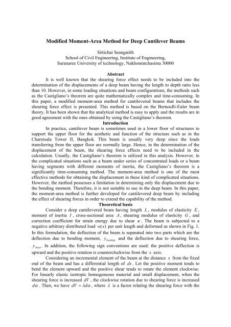
per unit length and de<strong>for</strong>med as shown in Fig. 1.<br />
In this <strong>for</strong>mulation, the deflection of the beam is separated into two parts which are the<br />
deflection due to bending moment, y bending and the deflection due to shearing <strong>for</strong>ce,<br />
y shear . In addition, the following sign conventions are used: the positive deflection is<br />
upward and the positive rotation is counterclockwise from the x axis.<br />
Considering an incremental element of the beam at the distance x from the fixed<br />
end of the beam and has a differential length of dx . Let the positive moment tends to<br />
bend the element upward and the positive shear tends to rotate the element clockwise.<br />
For linearly elastic isotropic homogeneous material and small displacement, when the<br />
shearing <strong>for</strong>ce is increased dV , the clockwise rotation due to shearing <strong>for</strong>ce is increased<br />
d α . Then, we have dV = λdα<br />
, where λ is a factor relating the shearing <strong>for</strong>ce with the
otation. Hence, the strain energy due to shearing <strong>for</strong>ce from the initial position to the<br />
final rotation β = V / λ is<br />
y<br />
U<br />
shear<br />
-w(x)<br />
L<br />
=<br />
L<br />
∫<br />
0<br />
2<br />
λβ dx<br />
(1)<br />
yshear<br />
ybending<br />
Fig. 1 <strong>Deep</strong> cantilevered beam and its elastic curve with positive sign convention.<br />
Comparing Eq. 1 with the well-known strain energy due to shearing <strong>for</strong>ce from<br />
L 2<br />
V<br />
classical theory, U shear = ∫κ<br />
dx , we have<br />
2GA<br />
0<br />
λ<br />
κ<br />
GA<br />
= (2)<br />
Now, let us consider Fig. 1, the total deflection of the beam can be written as<br />
y = ybending<br />
+ yshear<br />
(3)<br />
Differentiating Eq. 3 twice, we have<br />
2 2<br />
2<br />
d y d ybending<br />
d yshear<br />
= +<br />
2<br />
2<br />
2<br />
dx dx dx<br />
2<br />
d ybending<br />
dβ<br />
= +<br />
dx dx<br />
(4)<br />
According to the Bernoulli-Euler beam theory and the previously mentioned sign<br />
2<br />
d ybending<br />
conventions, we have 2<br />
dx<br />
M<br />
= and dV / dx = −w(<br />
x)<br />
. Also, if the factor λ is<br />
EI<br />
independent of x <strong>for</strong> a given portion of the beam, then<br />
2<br />
d y dθ<br />
M d(<br />
V / λ)<br />
= = +<br />
2<br />
dx dx EI dx<br />
(6)<br />
x
M w<br />
dθ<br />
= dx − dx<br />
(7)<br />
EI λ<br />
This equation states that the change d θ in the slope of the tangent on either side<br />
of an incremental element dx correspond to infinitesimal area under the M / EI diagram<br />
and the w / λ diagram, respectively. Integrating from point A on the beam to point B ,<br />
where B / A<br />
B<br />
B<br />
M<br />
θ B / A = ∫ dx −<br />
EI ∫<br />
A<br />
A<br />
w<br />
dx<br />
λ<br />
θ is the angle of the tangent at B measured with respect to the tangent at A<br />
and has unit in radian. The positive sign indicates that the angle is in clockwise direction.<br />
For a small displacement, the vertical deviation dt of the tangent on each side of<br />
the incremental element dx can be determined by using the circular arch <strong>for</strong>mula<br />
dt = xdθ<br />
. Then, the deviation of the tangent at point A to point B can be found as<br />
B<br />
B<br />
M w<br />
t B / A = ∫ xdx − xdx<br />
EI ∫<br />
(9)<br />
λ<br />
A<br />
A<br />
where positive sign indicates the upward vertical deviation. It should be noted that the<br />
Eq. 9 must be modified in the case of concentrated load due to dV / dx = 0 . Since we<br />
have d ( Vx)<br />
/ dx = [ V + x(<br />
dV / dx)]<br />
= V , then<br />
B<br />
M V<br />
t B / A = ∫ xdx − xdx<br />
EI ∫<br />
(10)<br />
λ<br />
A<br />
A<br />
Example: Determine the deflection and rotation at the end B of the deep<br />
cantilevered concrete beam as shown in Fig. 2 by using the modified moment area<br />
method. The beam has a rectangular cross-section with a constant width, b .<br />
Fig. 2 <strong>Deep</strong> cantilevered beam having rectangular cross-section with a constant width.<br />
in Fig. 3.<br />
y<br />
w(x)<br />
A B<br />
L/3 L/3 L/3<br />
L<br />
B<br />
V w M<br />
1. Draw the diagram, diagram, and diagram due to the loads as shown<br />
λ λ<br />
EI<br />
P<br />
h<br />
h/5<br />
h/5<br />
x<br />
(8)
P<br />
0.<br />
7143<br />
λ<br />
P<br />
0.<br />
8333<br />
λ<br />
V<br />
diagram due to the load P<br />
λ<br />
PL<br />
0.<br />
3644<br />
EI<br />
PL<br />
0.<br />
2430<br />
EI<br />
M<br />
diagram due to the load P<br />
EI<br />
+<br />
PL<br />
0.<br />
3858<br />
EI<br />
P<br />
λ<br />
w<br />
w<br />
w 0. 8333<br />
0. 7143<br />
λ<br />
λ<br />
λ<br />
- PL<br />
0.<br />
1929<br />
0.<br />
0810 -<br />
EI<br />
EI<br />
PL<br />
0.<br />
3333<br />
EI<br />
0.<br />
1822<br />
w<br />
diagram due to the load w<br />
λ<br />
M<br />
diagram due to the load w<br />
EI<br />
V w M<br />
Fig. 3 diagram, diagram, and diagram due to the applied loads.<br />
λ λ<br />
EI<br />
2. Determine the rotation at end B .<br />
θ B is equal to the total area between point A and B under M / EI diagram due<br />
to the load P plus M / EI diagram due to the load w plus w (x)<br />
/ λ diagram due to the<br />
load w .<br />
2<br />
3<br />
PL wL wL<br />
θ B = −0.<br />
2532 − 0.<br />
0659 − 0.<br />
8492κ<br />
EI EI GA<br />
The negative sign means that the rotation at B is in the clockwise direction.<br />
3. Determine the deflection at end B .<br />
t B / A is equal to the total moment about point B of the area between point A and<br />
B under M / EI diagram due to the load P plus M / EI diagram due to the load w plus<br />
w (x)<br />
/ λ diagram due to the load w and plus the area under V / λ diagram between point<br />
A and B .<br />
3<br />
4<br />
2<br />
PL wL<br />
wL<br />
PL<br />
t B / A = −0.<br />
1478 − 0.<br />
0437 − 0.<br />
3929κ<br />
− 0.<br />
8492κ<br />
EI EI<br />
GA GA<br />
The negative sign means that the deflection at B is in the downward direction.<br />
wL 2<br />
EI<br />
wL 2<br />
0.<br />
1286<br />
+<br />
0.<br />
0322<br />
wL 2<br />
EI<br />
wL 2<br />
EI<br />
0.<br />
0556<br />
wL 2<br />
EI
It should be noted that the obtained displacements are identical to the ones<br />
obtained by using the Castigliano’s theorem when the shear <strong>for</strong>ce effect is included.<br />
However, it was found that the Castigliano’s theorem is very lengthy and timeconsuming.<br />
Let the beam has E = 20.<br />
3GPa<br />
, G = 7.<br />
80 GPa , κ = 1.<br />
2 , b = 0.<br />
3 m , h = 1.<br />
0 m ,<br />
and L = 3.<br />
0 m , and is subjected to the loads w ( x)<br />
= 200 kN / m and P = 200 kN . The<br />
numerical values of the rotation and the deflection at the end B of the beam can be<br />
determined by using different calculation methods as shown in Table 1.<br />
Table 1. Comparison of the analytical results from the modified moment-area method and<br />
the structural analysis computer programs.<br />
<strong>Method</strong>s of Analysis Rotations Deflection<br />
<strong>Modified</strong> <strong>Moment</strong>-<strong>Area</strong> −3 1.<br />
860(<br />
10 ) rad<br />
3.<br />
592 mm<br />
Grasp −3 1.<br />
685(<br />
10 ) rad<br />
3.<br />
217 mm<br />
Ansys −3 1.<br />
685(<br />
10 ) rad<br />
3.<br />
641mm<br />
From Table 1., it can be seen that the rotations from the Grasp and Ansys program<br />
are identical and less than the result obtained by using the modified moment-area by<br />
9.4%. This is because the beam elements in the Grasp and Ansys program do not include<br />
the shear <strong>for</strong>ce effect in the calculation <strong>for</strong> the rotation. Also, the beam deflection<br />
obtained by using the modified moment-area is larger than the result from the Grasp<br />
program by 10.4%. However, since the shear <strong>for</strong>ce effect is included in the calculation<br />
<strong>for</strong> the deflection both in the Ansys program and in the modified moment-area method,<br />
the difference of the result is merely 1.4%. Thus, from the example, it can be seen that<br />
the shear <strong>for</strong>ce can contribute partially to the displacements of the beam and should not<br />
be neglected.<br />
Conclusions<br />
The moment-area method was modified by including the effect of shearing <strong>for</strong>ce<br />
<strong>for</strong> determining the displacements of the cantilevered beams. The calculation procedures<br />
are easy to apply as shown in the example, and the results are identical to ones obtained<br />
by using the Castigliano’s theorem and agree well with the results from the well- known<br />
structural analysis computer programs. This method is very effective <strong>for</strong> the beam having<br />
segments with different λ constants and moments of inertia. It is believed that the<br />
method should be useful to engineering designers because they can avoid the more<br />
complex flexural-shear-displacement analysis.<br />
References<br />
1. Langhaar, H.L. (1962). Energy methods in Applied Mechanics, Wiley.<br />
2. Gere, J.M. and Timoshenko, S.P. (1984). Mechanics of Materials,<br />
Brooks/Cole Engineering Division, Monterey, CA.<br />
nd<br />
2 ed.,


