Petrol engine twin Camshaft & Diesel engine ... - Tooled-Up.com
Petrol engine twin Camshaft & Diesel engine ... - Tooled-Up.com
Petrol engine twin Camshaft & Diesel engine ... - Tooled-Up.com

Create successful ePaper yourself
Turn your PDF publications into a flip-book with our unique Google optimized e-Paper software.
Instructions for:<br />
<strong>Petrol</strong> <strong>engine</strong> <strong>twin</strong> <strong>Camshaft</strong> &<br />
<strong>Diesel</strong> <strong>engine</strong> setting / loCking tool<br />
kit<br />
Model No: Vs4960<br />
Thank you for purchasing a Sealey product. Manufactured to a high standard this product will, if used according to these instructions<br />
and properly maintained, give you years of trouble free performance.<br />
IMPORTANT: Please reaD these instrUCtions CarefUllY. note the safe oPerational reQUirements, warnings anD CaUtions.<br />
Use the ProDUCt CorreCtlY anD with Care for the PUrPose for whiCh it is intenDeD. failUre to Do so maY CaUse Damage<br />
anD/or Personal inJUrY anD will inValiDate the warrantY. Please keeP instrUCtions safe for fUtUre Use.<br />
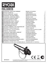
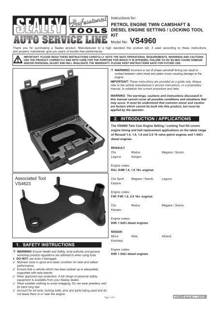
Associated Tool<br />
VS4623<br />
1. safetY instrUCtions<br />
Engine codes:<br />
warning! Ensure Health and Safety, local authority and general<br />
workshop practice regulations are adhered to when using tools.<br />
k9k 1.5dCi diesel <strong>engine</strong>s<br />
Do not use tools if damaged.<br />
Maintain tools in good and clean condition for best and safest<br />
performance.<br />
Ensure that a vehicle which has been jacked up is adequately<br />
supported with axle stands.<br />
Wear approved eye protection. A full range of personal safety<br />
equipment is available from your Sealey dealer.<br />
Wear suitable clothing to avoid snagging. Do not wear jewellery and<br />
tie back long hair.<br />
Account for all tools, locking bolts, pins and parts being used and do<br />
not leave them in or near the <strong>engine</strong>.<br />
Page 1 of 6<br />
warning! Incorrect or out of phase camshaft timing can result in<br />
contact between valve head and piston crown causing damage to the<br />
<strong>engine</strong>.<br />
IMPORTANT: These instructions are provided as a guide only. Always<br />
refer to the vehicle manufacturer’s service instructions, or a proprietary<br />
manual, to establish the current procedure and data.<br />
WARNING: The warnings, cautions and instructions discussed in<br />
this manual cannot cover all possible conditions and situations that<br />
may occur. It must be understood that <strong>com</strong>mon sense and caution<br />
are factors which cannot be built into this product, but must be<br />
applied by the operator.<br />
2. introDUCtion / aPPliCations<br />
the Vs4960 <strong>twin</strong> Cam <strong>engine</strong> setting / locking tool kit covers<br />
<strong>engine</strong> timing and belt replacement applications on the latest range<br />
of renault 1.4, 1.6, 1.8 and 2.0 16 valve petrol <strong>engine</strong>s and 1.5dCi<br />
diesel <strong>engine</strong>s.<br />
renaUlt<br />
Clio Modus Megane / Scenic<br />
Laguna Kangoo<br />
Engine codes:<br />
k4J, k4m 1.4, 1.6 16v. <strong>engine</strong>s<br />
Clio Sport Megane / Scenic Laguna<br />
Espace<br />
Engine codes:<br />
f4P, f4r 1.8, 2.0 16v. <strong>engine</strong>s<br />
Clio Modus Megane / Scenic<br />
Kangoo<br />
Engine codes:<br />
k9k 1.5dCi diesel <strong>engine</strong>s<br />
nissan<br />
Micra Note Almera<br />
Kurbistar<br />
VS4960 Issue No:1 - 23/07/08
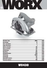
3. Contents<br />
1 . ....VS4561A .....<strong>Camshaft</strong> Setting Plate Set c/w Brackets<br />
2 . ....VS4562A .....Crankshaft Locking Pin<br />
3 . . . . . VS125/R1 ....Crankshaft Locking Pin<br />
-- .....VS4960/84. ...Case + Insert<br />
4. instrUCtions<br />
Vs4960 <strong>twin</strong> <strong>Camshaft</strong> <strong>engine</strong> setting / locking tool kit<br />
The VS4960 Twin Cam Engine Setting / Locking Tool Kit covers <strong>engine</strong><br />
timing and belt replacement applications on the latest range of Renault<br />
1.4, 1.6, 1.8 and 2.0 16 valve petrol <strong>engine</strong>s and 1.5dCi diesel <strong>engine</strong>s.<br />
The VS4561A <strong>Camshaft</strong> Setting Plate Set is used on both the K4J / K4M<br />
and F4P / F4R <strong>engine</strong>s. It includes the two location brackets required to<br />
cover the range of K4J / K4M <strong>engine</strong> variants. These brackets allow the<br />
Setting Plate to be secured correctly to the <strong>engine</strong>.<br />
Some K4J / K4M encountered will have a camshaft position sensor and<br />
therefore the Location Bracket Ref: VS4563 (included in the Set) will be<br />
required to attach the camshaft Setting Plate on these <strong>engine</strong>s. The<br />
Setting Plate locates into slots at the rear of the camshafts.<br />
note: To use VS4561A Plate Set the sealing plugs at the rear of the<br />
camshafts must be removed.<br />
VS4562A Crankshaft Locking Pin is applicable to K4J / K4M petrol<br />
<strong>engine</strong>s and K9K diesels, whilst the VS125/R1 Pin covers crankshaft<br />
locking on F4P / F4R petrol <strong>engine</strong>s and camshaft timing on 1.5dCi (K9K)<br />
<strong>engine</strong>s.<br />
4.1 <strong>engine</strong> setting & locking – timing Belt replacement<br />
It will be necessary to support the <strong>engine</strong> and remove the right-hand<br />
<strong>engine</strong> mounting.<br />
4.2 on 16v. petrol <strong>engine</strong>s, remove the sealing plugs from the rear of<br />
the camshafts. Turn the <strong>engine</strong> to its timing position and note that the<br />
slots in the end of the camshafts are aligned horizontally.<br />
note: The slots should be below the surface line of the cylinder head.<br />
(Fig.1).<br />
Fig.1<br />
Page 2 of 6<br />
Crankshaft - 16v. Pertrol <strong>engine</strong><br />
Fig.2<br />
4.2.1 Vs4562a and Vs125/r1 Crankshaft locking Pins<br />
Insert the appropriate Crankshaft Locking Pin.<br />
VS4562A is used for 1.4 and 1.6 K4J / K4M petrol and K9K diesel<br />
<strong>engine</strong>s.<br />
Remove the blanking plug for the crankshaft locking pin from the cylinder<br />
block and turn the crankshaft in a clockwise direction so that the<br />
camshaft is just before its alignment position. This will provide the correct<br />
crankshaft position for inserting the VS4562A Crankshaft Locking<br />
Pin. Screw in VS4562A Locking Pin and turn the crankshaft slightly until<br />
the “flat” on web of the crankshaft is pressing against the end of the pin.<br />
(Fig.2).<br />
Fig.3<br />
4.2.2 VS125/R1 is for the crankshaft on F4P / F4R <strong>engine</strong>s and when<br />
inserted it enters into the timing slot in the crankshaft.<br />
note: Ensure the pin is positioned in the timing slot and not into a<br />
crankshaft web hole.<br />
(Fig.3).<br />
Lock the flywheel and release the crankshaft pulley bolt and remove the<br />
crankshaft pulley.<br />
imPortant: Do not use Crankshaft Locking Pins to hold crankshaft in<br />
position whilst releasing or tightening the pulley bolt. Locking Pins are for<br />
retention of timing position only.<br />
warning: ensure that the crankshaft gear does not fall off the<br />
crankshaft.<br />
VS4960 Issue No:1 - 23/07/08
4.3 <strong>Camshaft</strong> – k9k dCi <strong>engine</strong>s<br />
Fig.4<br />
Non - Adjustable Sprocket<br />
Adjustable <strong>Camshaft</strong> Sprocket<br />
4.3 Vs125/r1 <strong>Camshaft</strong> locking Pin<br />
Insert VS125/R1 Pin through the timing hole in the camshaft sprocket<br />
and into the timing hole in the cylinder head. (Fig.4).<br />
note: Some 1.5 K9K <strong>engine</strong> variants have an adjustable camshaft<br />
sprocket (identified by 3 x sprocket retaining bolts to a camshaft carrier<br />
plate and elongated timing slot in the sprocket).<br />
4.3.1 Remove the crankshaft pulley, slacken the belt tensioner and<br />
remove belt.<br />
Once a belt has been removed, a new belt and tensioning rollers must be<br />
fitted.<br />
4.3.2 Check the positions of timing marks - the camshaft sprocket<br />
(positioned by Pin), the crankshaft (keyway vertically upwards) and<br />
the fuel pump (approx 1-o-clock position aligned with bolt head directly<br />
behind sprocket. i.e. one tooth to right of vertical axis).<br />
note: If the <strong>engine</strong> variant has an adjustable camshaft sprocket,<br />
remove one bolt and slacken the other two by one turn.<br />
4.3.3 Fit the new timing belt, <strong>com</strong>mencing at the crankshaft gear. Ensure<br />
that the marks on the belt are aligned with the timing marks on the<br />
camshaft, HP pump and crankshaft sprockets. There should be 19 tooth<br />
spaces between camshaft and HP pump timing marks and 51 tooth<br />
spaces between crankshaft and HP pump marks.<br />
Page 3 of 6<br />
4.4 <strong>Camshaft</strong> – 16v. <strong>Petrol</strong> <strong>engine</strong>s<br />
Fig.5a<br />
Fig.5b<br />
Vs4561a <strong>Camshaft</strong> setting Plate<br />
With the crankshaft ‘locked’ in position, check that the slots in the ends of<br />
the camshafts are aligned horizontally<br />
4.4.1 Construct the <strong>Camshaft</strong> Setting Plate Assembly by using the<br />
VS4561 Plate and attaching to it the appropriate Location Bracket – The<br />
Right-angled Bracket shown in (Fig.5a) or the Extended Bracket – shown<br />
in (Fig.5b).<br />
4.4.2 The Extended Bracket (VS4563) will be required when a camshaft<br />
position sensor is fitted on some K4J / K4M <strong>engine</strong>s in Clio III,<br />
scenic ii, laguna ii and modus<br />
Fit VS4561A Setting Plate securing it to the <strong>engine</strong> using the appropriate<br />
Location Bracket.<br />
Fig.6<br />
Slots in end of camshafts align horizontally and are below the surface line<br />
of the cylinder head. (Fig.6).<br />
4.4.3 Slacken tensioner and remove together with guide roller and timing<br />
belt.<br />
VS4960 Issue No:1 - 23/07/08
4.5 Belt guide removal<br />
1.4 / 1.6 16v. k4J / k4m <strong>engine</strong>s in Clio iii, megane / scenic ii,<br />
laguna ii, modus and kangoo.<br />
On timing belt replacement on these <strong>engine</strong>s,the belt guide roller must<br />
be removed and replaced.<br />
4.6 installing a new timing belt – 16v. <strong>Petrol</strong> <strong>engine</strong>s<br />
With VS4561A fitted and retaining the camshafts in position, and either<br />
VS4562A or VS125/R1 Pin ‘locking’ the crankshaft, fit a new guide roller<br />
and tensioner pulley. The pin on the tensioner locates into the slot in the<br />
cylinder head.<br />
Fig.7<br />
4.6.1 imPortant: It is vital to degrease the bore and contact surface<br />
of the crankshaft gear and pulley and end of crankshaft to prevent slip<br />
during re-assembly. (Fig.7).<br />
4.6.2 The new timing belt is fitted in an anti-clockwise direction<br />
<strong>com</strong>mencing at the crankshaft. Ensure it is taut on the non-tensioner<br />
side.<br />
4.6.3 Measure the crankshaft pulley bolt. If longer than 49.1mm. replace<br />
with new bolt.<br />
Fit crankshaft pulley – if reusing the original bolt, oil threads. If fitting a<br />
new bolt – Do not lubricate.<br />
4.6.4 imPortant: When installing do not fully tighten crankshaft bolt –<br />
leave approx. 2mm. clearance between pulley and bolt head.<br />
4.7 Belt tensioning<br />
4.7.1 initial tensioning– 16v. <strong>Petrol</strong> <strong>engine</strong>s<br />
Turn tensioner clockwise until…<br />
Fig.8<br />
K4J / K4M<br />
for k4J/k4m – moving pointer is at its right-hand stop position<br />
(7 to 8mm. past fixed pointer). (Fig.8).<br />
Page 4 of 6<br />
Fig.9<br />
F4P / F4R<br />
for f4P / f4r – tensioner marks align… and tighten nut. (Fig. 9).<br />
4.7.2 note: The <strong>engine</strong> is now rotated to equalise belt tension, however<br />
it is useful to be able to determine the point at which the <strong>engine</strong> has<br />
returned to just before its ‘timed’ position, to help with insertion of the<br />
crankshaft pin. Therefore mark the camshaft sprockets at the 12-0-clock<br />
position, with a paint/chalk mark and place a corresponding mark on the<br />
cylinder head directly behind them.<br />
Fig.10<br />
Mark camshafts / cylinder head. (Fig.10).<br />
4.7.3 Remove the <strong>Camshaft</strong> Setting Plate and Crankshaft Locking Pin.<br />
Lock the flywheel in position and tighten the crankshaft pulley bolt.<br />
4.7.4 Rotate the <strong>engine</strong> twice in a clockwise direction, returning to a<br />
point just before the timing position (use guide marks made earlier on<br />
camshaft sprockets).<br />
4.7.5 Insert the appropriate Crankshaft Locking Pin, VS4562A or VS125/<br />
R1 and carefully rotate the <strong>engine</strong> further to its ‘timed’ position ensuring<br />
correct location of Locking Pin in the crankshaft, as previously described.<br />
4.7.6 Check that the camshaft slots are aligned horizontally and are<br />
below the surface line of the cylinder head, and fit AST4561A <strong>Camshaft</strong><br />
Setting Plate ensuring it can be easily inserted.<br />
VS4960 Issue No:1 - 23/07/08
4.7.7 final tensioner positions– 16v. <strong>Petrol</strong> <strong>engine</strong>s<br />
Fig.11<br />
K4J / K4M<br />
k4J/k4m – Turn tensioner anti-clockwise until both pointers align.<br />
(Fig. 11).<br />
Fig.12<br />
F4P / F4R<br />
f4P / f4r – Check that the tensioner marks still align. If not – repeat<br />
tensioning procedure.<br />
(Fig.12).<br />
Remove all timing tools.<br />
Page 5 of 6<br />
4.8 timing adjustment – 1.4 / 1.6 k4J / k4m petrol <strong>engine</strong>s.<br />
Fig.13<br />
Vs4623 <strong>Camshaft</strong> sprocket locking tool<br />
associated tool – not in kit<br />
4.8.1 If the correct crankshaft and camshaft timing positions cannot be<br />
achieved and the VS4561A Setting Plate Assembly cannot be fixed in<br />
place after the VS4562A Crankshaft Locking Pin has been inserted, it<br />
may be necessary to release the camshaft sprocket bolts in order to<br />
make a timing adjustment.<br />
4.8.2 In order to release and tighten the camshaft sprocket bolts, the<br />
camshaft sprockets must be first ‘locked’ in place with Tool VS4623. This<br />
will counter-hold the sprockets whilst the bolts are released / tightened.<br />
(Fig.13).<br />
4.8.3 Insert VS4562A Crankshaft Locking Pin and fit Sprocket Locking<br />
Tool VS4623.<br />
Release the camshaft sprocket bolts and turn the camshafts so that Setting<br />
Plate assembly can be easily inserted.<br />
Tighten camshaft sprocket bolts and remove all tools.<br />
Check that the belt tensioner position is correct.<br />
VS4960 Issue No:1 - 23/07/08
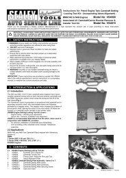
4.9 k9k 1.5dCi <strong>Diesel</strong> <strong>engine</strong>s - Belt tensioner Positions<br />
Fig.14<br />
K9K 1.5dCi diesel <strong>engine</strong>s<br />
4.9.1 Apply initial belt tension by turning the tensioner anti-clockwise<br />
so the “pointer” is positioned below the “notch” – see diagram above.<br />
(Fig.14).<br />
note: If adjustable camshaft sprocket fitted, check that the remaining<br />
two sprocket bolts are not at the end of their elongated slots. Re-fit the<br />
3rd bolt and tighten all 3 x sprocket retaining bolts<br />
4.9.2 Re-fit the crankshaft pulley and remove VS4562A and VS125/R1<br />
Locking Pins.<br />
4.9.3 Rotate the crankshaft two turns and return to a position where the<br />
crankshaft and camshaft locking pins can be inserted to check timing is<br />
correct, then remove the pins.<br />
4.9.4 For final tensioner position, slacken tensioner bolt (1 turn only) and<br />
adjust tensioner clockwise until the “pointer” aligns with the “notch”.<br />
NOTE: It is our policy to continually improve products and as such we reserve the right to alter data, specifications and <strong>com</strong>ponent parts without prior notice.<br />
imPortant: No liability is accepted for incorrect use of this product.<br />
warrantY: Guarantee is 12 months from purchase date, proof of which will be required for any claim.<br />
information: For a copy of our latest catalogue and promotions call us on 01284 757525 and leave your full name and address, including postcode.<br />
sole Uk Distributor<br />
sealey group,<br />
Bury St. Edmunds, Suffolk.<br />
Page 6 of 6<br />
01284 757500<br />
Web<br />
www.sealey.co.uk<br />
01284 703534 email sales@sealey.co.uk<br />
VS4960 Issue No:1 - 23/07/08