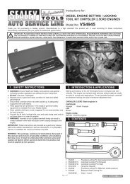
Petrol engine twin Camshaft & Diesel engine ... - Tooled-Up.com
Petrol engine twin Camshaft & Diesel engine ... - Tooled-Up.com
Petrol engine twin Camshaft & Diesel engine ... - Tooled-Up.com

You also want an ePaper? Increase the reach of your titles
YUMPU automatically turns print PDFs into web optimized ePapers that Google loves.
4.5 Belt guide removal<br />
1.4 / 1.6 16v. k4J / k4m <strong>engine</strong>s in Clio iii, megane / scenic ii,<br />
laguna ii, modus and kangoo.<br />
On timing belt replacement on these <strong>engine</strong>s,the belt guide roller must<br />
be removed and replaced.<br />
4.6 installing a new timing belt – 16v. <strong>Petrol</strong> <strong>engine</strong>s<br />
With VS4561A fitted and retaining the camshafts in position, and either<br />
VS4562A or VS125/R1 Pin ‘locking’ the crankshaft, fit a new guide roller<br />
and tensioner pulley. The pin on the tensioner locates into the slot in the<br />
cylinder head.<br />
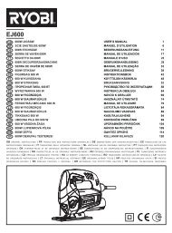
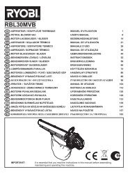
Fig.7<br />
4.6.1 imPortant: It is vital to degrease the bore and contact surface<br />
of the crankshaft gear and pulley and end of crankshaft to prevent slip<br />
during re-assembly. (Fig.7).<br />
4.6.2 The new timing belt is fitted in an anti-clockwise direction<br />
<strong>com</strong>mencing at the crankshaft. Ensure it is taut on the non-tensioner<br />
side.<br />
4.6.3 Measure the crankshaft pulley bolt. If longer than 49.1mm. replace<br />
with new bolt.<br />
Fit crankshaft pulley – if reusing the original bolt, oil threads. If fitting a<br />
new bolt – Do not lubricate.<br />
4.6.4 imPortant: When installing do not fully tighten crankshaft bolt –<br />
leave approx. 2mm. clearance between pulley and bolt head.<br />
4.7 Belt tensioning<br />
4.7.1 initial tensioning– 16v. <strong>Petrol</strong> <strong>engine</strong>s<br />
Turn tensioner clockwise until…<br />
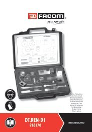
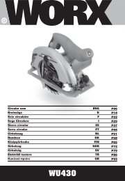
Fig.8<br />
K4J / K4M<br />
for k4J/k4m – moving pointer is at its right-hand stop position<br />
(7 to 8mm. past fixed pointer). (Fig.8).<br />
Page 4 of 6<br />
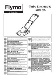
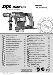
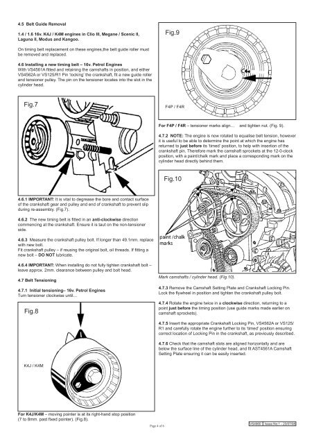
Fig.9<br />
F4P / F4R<br />
for f4P / f4r – tensioner marks align… and tighten nut. (Fig. 9).<br />
4.7.2 note: The <strong>engine</strong> is now rotated to equalise belt tension, however<br />
it is useful to be able to determine the point at which the <strong>engine</strong> has<br />
returned to just before its ‘timed’ position, to help with insertion of the<br />
crankshaft pin. Therefore mark the camshaft sprockets at the 12-0-clock<br />
position, with a paint/chalk mark and place a corresponding mark on the<br />
cylinder head directly behind them.<br />
Fig.10<br />
Mark camshafts / cylinder head. (Fig.10).<br />
4.7.3 Remove the <strong>Camshaft</strong> Setting Plate and Crankshaft Locking Pin.<br />
Lock the flywheel in position and tighten the crankshaft pulley bolt.<br />
4.7.4 Rotate the <strong>engine</strong> twice in a clockwise direction, returning to a<br />
point just before the timing position (use guide marks made earlier on<br />
camshaft sprockets).<br />
4.7.5 Insert the appropriate Crankshaft Locking Pin, VS4562A or VS125/<br />
R1 and carefully rotate the <strong>engine</strong> further to its ‘timed’ position ensuring<br />
correct location of Locking Pin in the crankshaft, as previously described.<br />
4.7.6 Check that the camshaft slots are aligned horizontally and are<br />
below the surface line of the cylinder head, and fit AST4561A <strong>Camshaft</strong><br />
Setting Plate ensuring it can be easily inserted.<br />
VS4960 Issue No:1 - 23/07/08