DTC P0013 Camshaft Position "B" Actuator Circuit / Open (Bank 1 ...
DTC P0013 Camshaft Position "B" Actuator Circuit / Open (Bank 1 ...
DTC P0013 Camshaft Position "B" Actuator Circuit / Open (Bank 1 ...

Create successful ePaper yourself
Turn your PDF publications into a flip-book with our unique Google optimized e-Paper software.
<strong>DTC</strong> <strong>P0013</strong><br />
<strong>DTC</strong> P0023<br />
2GR-FE ENGINE CONTROL SYSTEM – SFI SYSTEM<br />
ES–93<br />
<strong>Camshaft</strong> <strong>Position</strong> "B" <strong>Actuator</strong> <strong>Circuit</strong> / <strong>Open</strong><br />
(<strong>Bank</strong> 1)<br />
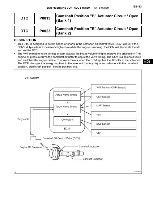
DESCRIPTION<br />
• This <strong>DTC</strong> is designed to detect opens or shorts in the camshaft oil control valve (OCV) circuit. If the<br />
OCV's duty-cycle is excessively high or low while the engine is running, the ECM will illuminate the MIL<br />
and set the <strong>DTC</strong>.<br />
• The VVT (variable valve timing) system adjusts the intake valve timing to improve the driveability. The<br />
engine oil pressure turns the camshaft actuator to adjust the valve timing. The OCV is a solenoid valve<br />
and switches the engine oil line. The valve moves when the ECM applies the 12 volts to the solenoid.<br />
The ECM changes the energizing time to the solenoid (duty-cycle) in accordance with the camshaft<br />
position, crankshaft position, throttle position, etc.<br />
Duty-cycle<br />
VVT System<br />
Engine Oil Pressure<br />
<strong>Camshaft</strong> <strong>Position</strong> "B" <strong>Actuator</strong> <strong>Circuit</strong> / <strong>Open</strong><br />
(<strong>Bank</strong> 2)<br />
Actual Valve Timing<br />
Target Valve Timing<br />
Correction<br />
ECM<br />
<strong>Camshaft</strong> Oil Control Valve (OCV)<br />
VVT Sensor (CMP Sensor)<br />
CKP Sensor<br />
MAF Sensor<br />
TPS<br />
ECT Sensor<br />
VSS<br />
<strong>Camshaft</strong> <strong>Actuator</strong><br />
Exhaust <strong>Camshaft</strong><br />
A130637E02<br />
ES
ES<br />
ES–94<br />
2GR-FE ENGINE CONTROL SYSTEM – SFI SYSTEM<br />
<strong>DTC</strong> No. <strong>DTC</strong> Detection Condition Trouble Area<br />
<strong>P0013</strong><br />
P0023<br />
MONITOR DESCRIPTION<br />
This <strong>DTC</strong> is designed to detect opens or shorts in the camshaft oil control valve (OCV) circuit. If the OCV's<br />
duty-cycle is excessively high or low while the engine is running, the ECM will illuminate the MIL and set<br />
the <strong>DTC</strong>.<br />
MONITOR STRATEGY<br />
<strong>Open</strong> or short in OCV for exhaust camshaft (bank 1)<br />
circuit<br />
(1 trip detection logic)<br />
<strong>Open</strong> or short in OCV for exhaust camshaft (bank 2)<br />
circuit<br />
(1 trip detection logic)<br />
TYPICAL ENABLING CONDITIONS<br />
TYPICAL MALFUNCTION THRESHOLDS<br />
COMPONENT OPERATING RANGE<br />
• <strong>Open</strong> or short in OCV for exhaust camshaft (bank<br />
1) circuit<br />
• OCV for exhaust camshaft (bank 1)<br />
• ECM<br />
• <strong>Open</strong> or short in OCV for exhaust camshaft (bank<br />
2) circuit<br />
• OCV for exhaust camshaft (bank 2)<br />
• ECM<br />
Related <strong>DTC</strong>s<br />
<strong>P0013</strong>: Exhaust camshaft OCV (bank 1)<br />
P0023: Exhaust camshaft OCV (bank 2)<br />
Required sensors / components (Main) Exhaust camshaft OCV<br />
Required sensors / components (Sub) -<br />
Frequency of operation Continuous<br />
Duration 1 second<br />
MIL operation Immediate<br />
Sequence of operation None<br />
Monitor runs whenever following <strong>DTC</strong>s not present None<br />
All of following conditions met -<br />
Starter OFF<br />
Ignition switch ON<br />
Time after ignition switch OFF to ON 0.5 seconds or more<br />
One of following conditions met -<br />
A. All of following conditions met -<br />
Battery voltage 11 to 13 V<br />
Target duty ratio Less than 70%<br />
Output signal duty ratio 100%<br />
B. All of following conditions met -<br />
Battery voltage 13 V or more<br />
Target duty ratio Less than 80%<br />
Output signal duty ratio 100%<br />
Exhaust VVT oil control valve condition No operation record<br />
OCV duty-cycle 4 to 100% when engine running
WIRING DIAGRAM<br />
B57<br />
OCV for Exhaust <strong>Camshaft</strong> (for <strong>Bank</strong> 1)<br />
B43<br />
OCV for Exhaust <strong>Camshaft</strong> (for <strong>Bank</strong> 2)<br />
1<br />
2<br />
1<br />
2<br />
2GR-FE ENGINE CONTROL SYSTEM – SFI SYSTEM<br />
ES–95<br />
INSPECTION PROCEDURE<br />
HINT:<br />
• If <strong>DTC</strong> <strong>P0013</strong> is displayed, check the bank 1 VVT system for exhaust camshaft circuit.<br />
• <strong>Bank</strong> 1 refers to the bank that includes No. 1 cylinder.<br />
• If <strong>DTC</strong> P0023 is displayed, check the bank 2 VVT system for exhaust camshaft circuit.<br />
• <strong>Bank</strong> 2 refers to the bank that does not include No. 1 cylinder.<br />
• Read freeze frame data using the intelligent tester. The ECM records vehicle and driving condition<br />
information as freeze frame data the moment a <strong>DTC</strong> is stored. When troubleshooting, freeze frame<br />
data can be helpful in determining whether the vehicle was running or stopped, whether the engine<br />
was warmed up or not, whether the air-fuel ratio was lean or rich, as well as other data recorded at the<br />
time of a malfunction (See page ES-40).<br />
1 CHECK <strong>DTC</strong> (<strong>DTC</strong> <strong>P0013</strong> OR P0023)<br />
(a) Connect the intelligent tester to the DLC3.<br />
(b) Clear <strong>DTC</strong> after recording the freeze frame data and<br />
<strong>DTC</strong>.<br />
(c) Turn the ignition switch OFF.<br />
(d) Allow the engine to idle and check <strong>DTC</strong>.<br />
(e) Check that <strong>P0013</strong> or P0023 is present.<br />
OK:<br />
<strong>P0013</strong> or P0023 is present<br />
NG<br />
56<br />
OE1+<br />
B30<br />
55<br />
OE1-<br />
B30<br />
50<br />
OE2+<br />
B30<br />
49<br />
B30<br />
OE2-<br />
ECM<br />
CHECK FOR INTERMITTENT PROBLEMS<br />
A136189E02<br />
ES
ES<br />
ES–96<br />
OK<br />
OK<br />
OK<br />
2GR-FE ENGINE CONTROL SYSTEM – SFI SYSTEM<br />
2 INSPECT CAMSHAFT TIMING OIL CONTROL VALVE ASSEMBLY<br />
A095415E03<br />
(a) Disconnect the B43 or B57 OCV connector.<br />
(b) Remove the OCV.<br />
(c) Measure the resistance between the terminals of the<br />
OCV.<br />
Standard resistance:<br />
6.9 to 7.9 Ω at 20°C (68°F)<br />
(d) Reconnect the OCV connector.<br />
NG<br />
3 CHECK WIRE HARNESS (OCV - ECM)<br />
Wire Harness Side:<br />
B57<br />
B43<br />
<strong>Bank</strong> 1<br />
<strong>Bank</strong> 2<br />
B30<br />
OCV<br />
ECM<br />
OE2- OE2+ OE1- OE1+<br />
A106380E12<br />
REPLACE ECM<br />
(a) Disconnect the B43 or B57 OCV connector.<br />
(b) Disconnect the B30 ECM connector.<br />
(c) Measure the resistance.<br />
Standard resistance<br />
(d) Reconnect the OCV connector.<br />
(e) Reconnect the ECM connector.<br />
NG<br />
REPLACE CAMSHAFT TIMING OIL<br />
CONTROL VALVE ASSEMBLY<br />
Tester Connection Specified Condition<br />
B57-1 - B30-56 (OE1+) Below 1 Ω<br />
B57-2 - B30-55 (OE1-) Below 1 Ω<br />
B43-1 - B30-50 (OE2+) Below 1 Ω<br />
E43-2 - B30-49 (OE2-) Below 1 Ω<br />
B57-1 or B30-56 (OE1+) - Body<br />
ground<br />
10 kΩ or higher<br />
B57-2 or B30-55 (OE1-) - Body<br />
ground<br />
B43-1 or B30-50 (OE2+) - Body<br />
ground<br />
E43-2 or B30-49 (OE2-) - Body<br />
ground<br />
10 kΩ or higher<br />
10 kΩ or higher<br />
10 kΩ or higher<br />
REPAIR OR REPLACE HARNESS AND<br />
CONNECTOR