Barnett's Manual of Bicycle Repair
Barnett's Manual of Bicycle Repair
Barnett's Manual of Bicycle Repair

You also want an ePaper? Increase the reach of your titles
YUMPU automatically turns print PDFs into web optimized ePapers that Google loves.
This chapter has several sections. It should be read<br />
carefully to prepare for using all the other chapters.<br />
The first section is <br />
This section covers only the most<br />
basic and universal terms. The other chapters will<br />
each start with a terminology section with terms that<br />
are more specific.<br />
The second section is Understanding<br />
thread descriptions and thread types is perhaps the<br />
most important basic mechanical skill.<br />
The third section is Press fits are a<br />
means <strong>of</strong> holding pieces together other than by threading<br />
them. It is a system with its own unique set <strong>of</strong><br />
techniques and rules.<br />
The fourth section is Understanding<br />
the proper use <strong>of</strong> greases and oils is critical to being<br />
a good mechanic.<br />
The fourth section is <br />
This section covers what types <strong>of</strong> cleansers, solvents<br />
and polishes might be used, and how to use<br />
them properly.<br />
The last section is This section covers use<br />
<strong>of</strong> common mechanic’s tools. The other chapters describe<br />
how to use bicycle mechanic specific tools. A<br />
list <strong>of</strong> recommended tools is in the appendix.<br />
<br />
<br />
Chapters on individual component areas <strong>of</strong> the<br />
bicycle have more specific terminology and definitions.<br />
For the purpose <strong>of</strong> this manual, the following terms<br />
apply to the frame and basic components.<br />
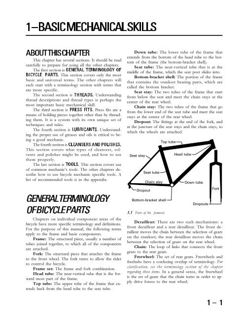
Frame: The structural piece, usually a number <strong>of</strong><br />
tubes joined together, to which all <strong>of</strong> the components<br />
are attached.<br />
Fork: The structural piece that attaches the frame<br />
to the front wheel. The fork turns to allow the rider<br />
to control the bicycle.<br />
Frame set: The frame and fork combination.<br />
Head tube: The near-vertical tube that is the forward<br />
most part <strong>of</strong> the frame.<br />
Top tube: The upper tube <strong>of</strong> the frame that extends<br />
back from the head tube to the seat tube.<br />
Down tube: The lower tube <strong>of</strong> the frame that<br />
extends from the bottom <strong>of</strong> the head tube to the bottom<br />
<strong>of</strong> the frame (the bottom-bracket shell).<br />
Seat tube: The near-vertical tube that is at the<br />
middle <strong>of</strong> the frame, which the seat post slides into.<br />
Bottom-bracket shell: The portion <strong>of</strong> the frame<br />
that contains the crankset bearing parts, which are<br />
called the bottom bracket.<br />
Seat stay: The two tubes <strong>of</strong> the frame that start<br />
from below the seat and meet the chain stays at the<br />
center <strong>of</strong> the rear wheel.<br />
Chain stay: The two tubes <strong>of</strong> the frame that go<br />
from the lower end <strong>of</strong> the seat tube and meet the seat<br />
stays at the center <strong>of</strong> the rear wheel.<br />
Dropout: The fittings at the end <strong>of</strong> the fork, and<br />
at the juncture <strong>of</strong> the seat stays and the chain stays, to<br />
which the wheels are attached.<br />
Seat stay<br />
Dropout<br />
Seat tube<br />
Chain stay<br />
Bottom-bracket shell<br />
1.1 Parts <strong>of</strong> the frameset.<br />
Top tube<br />
Head tube<br />
Down tube<br />
Dropouts<br />
Fork<br />
Derailleur: There are two such mechanisms: a<br />
front derailleur and a rear derailleur. The front derailleur<br />
moves the chain between the selection <strong>of</strong> gears<br />
on the crankset; the rear derailleur moves the chain<br />
between the selection <strong>of</strong> gears on the rear wheel.<br />
Chain: The loop <strong>of</strong> links that connects the front<br />
gears to the rear gears.<br />
Freewheel: The set <strong>of</strong> rear gears. Freewheels and<br />
freehubs have a confusing overlap <strong>of</strong> terminology. For<br />
clarification, see the terminology section <strong>of</strong> the chapter<br />
regarding these items. In a general sense, the freewheel<br />
is the set <strong>of</strong> gears that the chain turns in order to apply<br />
drive forces to the rear wheel.
Crankset: The mechanism that is turned by the<br />
rider’s feet. It consists <strong>of</strong> two lever arms called crankarms,<br />
one to three gears called chainrings, and a bearing<br />
assembly that the crank arms rotate around called<br />
the bottom bracket.<br />
Bottom bracket: The bearing assembly that allows<br />
the crankset to rotate in the bottom-bracket shell.<br />
<br />
<br />
<br />
<br />
1.2 Parts <strong>of</strong> the drivetrain.<br />
<br />
<br />
<br />
Wheel: The assembly consisting <strong>of</strong> the hub,<br />
spokes, rim, tire and tube.<br />
Hub: The assembly at the center <strong>of</strong> the wheel that<br />
houses the axle bearings, and to which spokes attach.<br />
Freehub: A hub and freewheel that have been<br />
combined into a single integrated assembly.<br />
Spokes: The tensioned wires that join the hub and<br />
rim together.<br />
Rim: The hoop at the outer edge <strong>of</strong> the wheel to<br />
which the tire is mounted.<br />
Tire: The rubber hoop at the outer edge <strong>of</strong> the<br />
wheel assembly.<br />
<br />
<br />
1.3 Parts <strong>of</strong> the wheel.<br />
Headset: The bearing assembly that connects the<br />
fork to the frame and allows the fork to rotate inside<br />
the head tube.<br />
Pedal: A mechanism that supports the rider’s<br />
foot. It contains a bearing assembly and is mounted<br />
to the crank arm.<br />
Seat post: The pillar (usually a tube <strong>of</strong> metal) that<br />
attaches the seat to the frame.<br />
Saddle: The s<strong>of</strong>t structure that supports the<br />
rider’s posterior.<br />
Stem: The piece that connects the handlebars to<br />
the fork.<br />
Handlebar: The piece that supports the rider’s<br />
hands and is turned to control the bike.<br />
Brake lever: The levers that are operated by the<br />
rider’s hands to control the braking function.<br />
Shift lever: The levers operated by the rider’s<br />
hands that control the derailleurs.<br />
Brake caliper: The mechanisms that squeeze<br />
against the rims to control the bike’s speed.<br />
<br />
<br />
One <strong>of</strong> the key challenges to the mechanic is to<br />
be able to replace or upgrade parts with compatible<br />
parts. One <strong>of</strong> the most significant obstacles to be overcome<br />
is the number <strong>of</strong> different thread standards used<br />
on bicycles. For example rear axles alone come in seven<br />
different varieties. Threads are described by a two part<br />
number, such as 3/8" × 26tpi or 10mm × 1mm. The<br />
first number refers to the diameter <strong>of</strong> the male version<br />
<strong>of</strong> the thread and the second number refers to<br />
the pitch. When identifying a thread, start with pitch.<br />
The first step to identifying a thread is to measure<br />
the pitch with a pitch gauge. Pitch is a measurement <strong>of</strong><br />
the frequency <strong>of</strong> threads, or the distance from one thread<br />
to the next. In an inch system (BSC and Whitworth),<br />
pitch is measured by the number <strong>of</strong> threads that occur<br />
in one inch <strong>of</strong> thread length, and in a metric system<br />
pitch is the distance from one thread to the next.<br />
Pitch is measured with a pitch gauge by mating<br />
the gauge to the thread. If the gauge can be held down<br />
in the thread at both ends simultaneously, the thread<br />
is identified (see figure 1.4). The best pitch gauges available<br />
come with both metric and Whitworth gauges.<br />
Although Whitworth is quite rare, Whitworth pitch<br />
gauges are compatible with the BSC (British Standard<br />
Cycle) threads found on many bicycle parts. Although<br />
gauges are not normally marked with the appropriate<br />
units, the thread is metric whenever the number in-
cludes a decimal point, and the pitch is in inches whenever<br />
the number on the gauge is followed by the letter<br />
“G” or the letters “TPI” (for Threads Per Inch).<br />
<br />
<br />
<br />
<br />
<br />
<br />
1.4 When the teeth <strong>of</strong> the thread pitch gauge will all go into the<br />
threads simultaneously, then the gauge matches the thread.<br />
The next step to thread identification is to measure<br />
the diameter. Diameter is a measurement <strong>of</strong> the<br />
male thread’s outside diameter (O.D.). It is usually a<br />
nominal measurement. A measurement is a nominal<br />
measurement when an actual measurement is rounded<br />
up to an even number. For example, a thread with a<br />
6mm diameter is only nominally 6mm. The actual<br />
diameter is more like 5.9mm.<br />
Metric bicycle threads are available in .5 millimeter<br />
increments, so always round the actual measurement<br />
up to the nearest .5mm to arrive at the nominal<br />
measurement. Inch bicycle threads are available in<br />
minimum 1/16 inch increments, so always round up<br />
to the nearest 1/16 inch or its decimal equivalent to<br />
arrive at the nominal measurement.<br />
Examples:<br />
If the thread measures 5.9mm— it is 6.0mm.<br />
If the thread measures .370"— it is .375".<br />
If the thread measures 23/64"— it is 3/8".<br />
Diameter may be measured in inches or millimeters.<br />
The best way to determine which units to use is<br />
by measuring the pitch first, because the diameter is<br />
almost always in the same units (a 1.0mm pitch<br />
threaded item is sure to have a metric diameter). The<br />
exceptions are on Italian-manufactured frames, which<br />
have metric diameter and inch pitch on the fork and<br />
in the bottom-bracket shell, and on Italian-made hubs,<br />
which may have metric diameter axles with inch pitch.<br />
Italian bikes will also have this combination <strong>of</strong> metric<br />
diameter and inch pitch on the freewheel mounting<br />
threads, but in this case it is not an issue because the<br />
Italian thread happens to be compatible with the com-<br />
<br />
mon BSC freewheel threads. Also, Jou Yu (Joy Tech)<br />
hub axles have metric diameter combined with inch<br />
pitch in some inconsistent cases.<br />
When measuring diameter use a caliper. Measure<br />
the thread with the axis <strong>of</strong> the thread perpendicular<br />
to the face <strong>of</strong> the caliper, the axle centered in the caliper<br />
jaws and not on any slot in the threads.<br />
0 1<br />
0 1<br />
<br />
.5<br />
.5<br />
.6<br />
.4<br />
.6<br />
.4<br />
.7<br />
.3<br />
.7<br />
.3<br />
.8<br />
.2<br />
.8<br />
.2<br />
.9<br />
.1<br />
.9<br />
.1<br />
0<br />
0<br />
0<br />
0<br />
.1<br />
.9<br />
<br />
<br />
<br />
<br />
<br />
.1<br />
.9<br />
<br />
<br />
<br />
<br />
1.5 Correct and incorrect ways to measure thread diameter.<br />
.2<br />
.8<br />
.2<br />
.8<br />
.3<br />
.7<br />
.3<br />
.7<br />
.4<br />
.5<br />
.6<br />
.4<br />
.5<br />
.6
Female thread diameters are rarely provided.<br />
When the pitch is 24tpi, 26tpi, or 1mm the inside<br />
diameter will be approximately .7–.9mm less than<br />
the male.<br />
Following is a chart <strong>of</strong> useful equivalents <strong>of</strong> thread<br />
diameter. Start by taking a measurement in inches or<br />
millimeters and then look in the right-most column<br />
for the nominal thread diameter.<br />
(table 1-1)<br />
<br />
<br />
<br />
7.7mm .303" 5/16"<br />
9.4mm .366" 3/8"<br />
12.5mm .492" 1/2"<br />
14.1mm .555" 9/16"<br />
25.2mm .992" 1"<br />
28.4mm 1.118" 1–1/8"<br />
31.6mm 1.244" 1–1/4"<br />
34.7mm 1.366" 1–3/8"<br />
<br />
<br />
<br />
.149" 3.8mm 4.0mm<br />
.189" 4.8mm 5.0mm<br />
.228" 5.8mm 6.0mm<br />
.307" 7.8mm 8.0mm<br />
.351" 8.8mm 9.0mm<br />
.346" 9.3mm 9.5mm<br />
.389" 9.8mm 10.0mm<br />
.976" 24.8mm 25.0mm<br />
1.358" 34.5mm 34.7mm<br />
1.370" 34.8mm 35.0mm<br />
1.409" 35.8mm 36.0mm<br />
On all pedals and most bottom-bracket threads<br />
(as well as other rare occurrences), the final aspect <strong>of</strong><br />
thread identification is the thread direction. Right-hand<br />
threads (most common) tighten or are installed with a<br />
clockwise rotation and loosen or are removed with a<br />
counterclockwise rotation. Left-hand threads (left pedals,<br />
some right-hand-side bottom-bracket parts, and<br />
certain freewheel cones and dust caps) tighten or are<br />
installed with a counterclockwise rotation and loosen<br />
or are removed with a clockwise rotation.<br />
Thread direction <strong>of</strong> male threads may be identified<br />
by observation. Held vertically, the threads on a<br />
right-hand thread will slope up to the right, and the<br />
threads on a left-hand thread will slope up to the left<br />
(see figure 1.6).<br />
<br />
<br />
<br />
<br />
<br />
1.6 Whether the thread slopes up to the left or up to the right shows<br />
the thread direction.<br />
Female threads may be identified as left or right<br />
by the following test. Install a matching thread pitch<br />
gauge into the thread in question with exactly one<br />
tooth <strong>of</strong> the gauge left outside the thread. Rotate the<br />
gauge in the threads at least one-half turn clockwise.<br />
Observe the amount <strong>of</strong> gauge teeth outside the thread<br />
at this point. If they have increased, it is a left-hand<br />
thread. If they have decreased, it is a right-hand thread.<br />
If the gauge is rotated counterclockwise instead <strong>of</strong><br />
clockwise, the results will be opposite.<br />
<br />
<br />
<br />
1.7 Rotate a thread pitch gauge in a female thread to determine<br />
the thread direction.<br />
<br />
It is helpful to know what threads are likely to be<br />
encountered in certain situations. The country <strong>of</strong> origin<br />
<strong>of</strong> a bicycle frame is likely to determine the thread used in<br />
the bottom bracket and the fork/headset. Different countries<br />
tend to use different thread standards. The standards<br />
are BSC (British Standard Cycle), Metric, Italian<br />
Whitworth, and ISO. ISO stands for the International<br />
Standards Organization. The ISO has adopted many existing<br />
thread descriptions to be the ISO standard. Some <strong>of</strong><br />
these existing threads are metric, and some are BSC. ISO<br />
standard threads may have a metric or inch description.<br />
<strong>Bicycle</strong> frames made in Taiwan, and Japan are certain<br />
to be BSC or ISO thread. <strong>Bicycle</strong> frames made in<br />
the U.S. are also virtually certain to be BSC or ISO thread,<br />
but sometimes small manufacturers <strong>of</strong> top end racing<br />
bikes use Italian threads. <strong>Bicycle</strong> frames made in Italy are<br />
virtually certain to be Italian thread. French bicycles are<br />
the greatest source <strong>of</strong> confusion because they used to be<br />
French thread, then switched to Swiss thread, and finally<br />
have switched to ISO threading. <strong>Bicycle</strong> frames from<br />
other countries are seen much more rarely, and it is best<br />
to rely strictly on measurements in these cases. See the<br />
bottom bracket and headset chapters for description <strong>of</strong><br />
BSC, ISO, French, Swiss, and Italian threads.
The country <strong>of</strong> origin <strong>of</strong> a component is useful in<br />
determining the thread type <strong>of</strong> fittings within the component,<br />
but the threads that attach a component to another<br />
component or the frame may be unrelated to the country<br />
<strong>of</strong> origin. For example a bottom bracket made in Japan<br />
for an Italian bicycle would be Italian thread. Another<br />
example would be that an Italian made freewheel installed<br />
as original equipment on an older French bicycle would<br />
probably be a French thread. The threads used within<br />
any Japanese, Taiwanese, or French component are likely<br />
to be metric. The threads used within any Italian component<br />
are likely to be metric or Italian Whitworth (a bizarre<br />
combination <strong>of</strong> metric diameter and inch pitch).<br />
There is little consistency with U.S. component manufacturers<br />
to use metric or inch threads. Those U.S. component<br />
“manufacturers” that contract to have their products<br />
made in Asia are more likely to use metric threads. For<br />
example, Grip Shift uses metric threads on fittings, but<br />
fittings on Bullseye hubs use inch pitch threads.<br />
<br />
<br />
The primary form <strong>of</strong> thread preparation is lubrication.<br />
Preparation <strong>of</strong> threads with oil or grease permits<br />
ease <strong>of</strong> assembly and disassembly. Lubrication<br />
makes it easier to feel when the threaded component<br />
is becoming tight enough. Corrosion is also prevented<br />
by lubrication; however, lubrication is counter effective<br />
on threads with nylon inserts.<br />
In most cases the lubrication choice is between oil<br />
and grease. Oil is generally used on threads <strong>of</strong> small<br />
diameter or fine pitch. Ease <strong>of</strong> application is the primary<br />
advantage compared to grease. Grease is used<br />
on threads <strong>of</strong> larger diameter and coarser threads. Its<br />
advantage over oil is durability under exposure to<br />
moisture and less <strong>of</strong> a tendency to evaporate.<br />
In some cases it is preferable to use a compound called<br />
Loctite instead <strong>of</strong> lubrication. Loctite is a liquid that hardens<br />
and expands after application. It is not a glue, but<br />
works by expanding to fill a gap and exerting pressure<br />
between the parts. Loctite used on threads aids ease <strong>of</strong><br />
assembly, prevents corrosion, prevents threaded components<br />
from coming loose and consequentially reduces<br />
the need to over-tighten parts, risking their damage.<br />
Loctites generally cure in a few hours. The hard cake<br />
that Loctite compounds cure into is not an adhesive. The<br />
hard cake deteriorates if the threaded item is turned after<br />
curing. Use <strong>of</strong> Loctite is redundant on threads with nylon<br />
inserts. (Loctite is toxic– minimize contact.)<br />
There are several grades <strong>of</strong> Loctite. Some <strong>of</strong> the<br />
following grades are available from automotive stores<br />
or United <strong>Bicycle</strong> Tool Supply, but some must be<br />
purchased at industrial bearing supply companies.<br />
<br />
Loctite 222 is the lightest grade available and is applicable<br />
on thread diameters up to 6mm. Typical uses<br />
<strong>of</strong> Loctite 222 include: accessory mounting bolts/nuts,<br />
brake mounting bolts/nuts, and derailleur limit screws.<br />
If only one grade <strong>of</strong> Loctite were to be used, it<br />
should be Loctite 242. It is heavier than the 222, and<br />
is used on larger diameter threads. Typical uses <strong>of</strong><br />
Loctite 242 include bottom-bracket fixed cups and<br />
headset locknuts, but it is also acceptable to use it on<br />
smaller thread diameters.<br />
Loctite 290 is a special application thread locker<br />
that is more heavy-duty than 242, but can be applied<br />
to already assembled components to penetrate into<br />
the threads. Typical uses <strong>of</strong> Loctite 290 include already<br />
installed accessories (such as fenders) and already installed<br />
bottom-bracket fixed cups.<br />
Loctite 272 or 277 are extremely heavy-duty compounds<br />
that would not allow removal without damage<br />
to the tool or part. They are used when threads<br />
are damaged and as an alternative to replacement when<br />
permanent installation will not be a problem.<br />
Loctite RC680 serves as a substitute for 272/277<br />
and can be used in other non-thread applications on<br />
the bike, such as enhancing the security <strong>of</strong> a pressedin<br />
part like a headset cup.<br />
Loctite 660 (Quick Metal) is not applicable to threads<br />
at all, but will fill gaps for press fits <strong>of</strong> up to .5mm.<br />
When assembling threads pay close attention to<br />
how they feel. Threads that feel tight during assembly<br />
should be checked for:<br />
Thread compatibility<br />
Paint in threads (Clean with tap.)<br />
Damaged threads (Clean with tap, die, thread<br />
chaser or file.)<br />
Cross-threading (Restart thread with better<br />
alignment.)<br />
That threads feel effortless to assemble is not by itself<br />
an indication <strong>of</strong> thread compatibility. When the female<br />
thread is a larger diameter than the male, no effort<br />
will be required for assembly, even when there is a pitch<br />
mismatch. If pitch match has not been verified but the<br />
difference between the O.D and I.D. <strong>of</strong> the parts is acceptable,<br />
then it is acceptable to use test-mating <strong>of</strong> parts<br />
as a way to determine compatibility. This is a useful technique<br />
in cases where it is impractical to check the pitch<br />
because <strong>of</strong> small I.D., or short overall thread length.<br />
A thread that gets tight and then feels easier to<br />
turn as it is secured is probably stripping.
Ideally, when threads are damaged the part should<br />
be replaced. If tools are available and the damage is<br />
not too severe, it may be possible to repair the thread.<br />
The best repair will be accomplished with a thread<br />
cutting tool such as a tap (for internal threads) or die<br />
(for external threads). When repairing threads with a<br />
tap or die, first make sure the damaged thread and tap<br />
or die have compatible thread description. Start the<br />
tap or die on the end <strong>of</strong> the threaded item that is in<br />
the best condition to ensure proper alignment.<br />
If the die is a variety with a split in it so it can be<br />
compressed or expanded, it should be fit in a special<br />
die handle that has expansion and compression adjusters.<br />
Thread the die onto the good portion <strong>of</strong> the thread<br />
with it expanded to a loose fit. Then compress it until<br />
it is barely snug before starting to cut on the threads<br />
that need repair.<br />
An alternative to using a tap or die is to use a thread<br />
chaser. A thread chaser does not actually cut threads.<br />
It does realign threads that have been mangled. It is<br />
most <strong>of</strong>ten used on solid axles or the dustcap threads<br />
in crank arms.<br />
The least expensive way to repair a thread is with<br />
a thread file. The thread file is best when there is just<br />
a small ding in a thread. Thread files can be used on<br />
mangled male threads. Available from various bicycle<br />
tool and general tool suppliers, thread files come in<br />
both inch and metric pitches. After matching the pitch<br />
on the file to the pitch <strong>of</strong> the thread being repaired,<br />
the file is then stroked in the direction <strong>of</strong> the thread<br />
angle, while the item being repaired is slowly rotated.<br />
1.8 To use a thread file, match the file pitch to the thread pitch,<br />
then stroke the file at the angle <strong>of</strong> the thread while rotating the<br />
threaded item.<br />
Stripped threads can sometimes be repaired just<br />
by chasing them with the appropriate tap, die, or<br />
thread chaser. If the thread still does not hold after<br />
this repair, repair options include use <strong>of</strong> Loctite 277<br />
or RC680, drilling the damaged thread out to a larger<br />
<br />
diameter and re-tapping to use a new size, or replacing<br />
the damaged part. Using Loctite is a solution only<br />
when there is no further need to remove the part.<br />
Converting to a larger diameter thread may be limited<br />
by available material or parts. Replacing the damaged<br />
part has no disadvantage, except cost or limitations<br />
<strong>of</strong> availability.<br />
To repair a stripped thread by going to the next larger<br />
diameter, first drill out the old threads to the appropriate<br />
size for the tap that will create the new thread. When<br />
drilling to tap, the use <strong>of</strong> a larger bit than recommended<br />
will lead to poor thread depth and will probably result<br />
in further thread failure. The use <strong>of</strong> a smaller bit than<br />
recommended will result in the tap jamming and breaking<br />
<strong>of</strong>f in the hole. To determine the correct drill size a<br />
simple formula can be used. If it is a metric thread, subtract<br />
the pitch from the nominal diameter <strong>of</strong> the thread;<br />
for example, converting a stripped 4.5mm × .8mm female<br />
thread to 5mm × .8mm requires drilling the hole<br />
out to 4.2mm (5.0 – .8 = 4.2). Another example: the<br />
correct tap drill for tapping a 6mm × 1mm thread would<br />
be 5mm (6 – 1 = 5). For inch thread (which is unlikely<br />
to be needed due to the rare use on inch threads on bicycles),<br />
a special or unusual drill bit size is needed. Inch<br />
size threads require “tap drills” which are unique sizes<br />
that are numbered instead <strong>of</strong> described by dimension.<br />
After drilling out the hole use the appropriate tap for the<br />
new thread size.<br />
<br />
<br />
To remove a stubborn nut or bolt first use a penetrating<br />
oil and allow to soak for a few minutes. Then<br />
use the best-fitting tool possible. If it is a screwdriver,<br />
apply heavy, downward force while turning the screw.<br />
If a screw or bolt head is deformed in the attempt to<br />
remove it, try vise grips locked securely on the head. If<br />
vise grips fail, use a small saw (Dremel or rotary tool)<br />
to cut a slot in the head to fit a slotted screwdriver.<br />
Another alternative is to file flats on the side <strong>of</strong> the bolt<br />
or nut head to fit an open-end wrench. If all <strong>of</strong> the<br />
above fail, the next option is to drill a hole in the bolt<br />
or screw between one-half and three-quarters <strong>of</strong> the bolt<br />
diameter and then hammer in a screw extractor to turn<br />
out the bolt. The screw extractor is the first option if<br />
the screw or bolt head shears <strong>of</strong>f. The last resort is to<br />
carefully drill the bolt out with the tap drill that is the<br />
appropriate size for the existing thread diameter. The<br />
method for determine the correct size for the drill bit is<br />
covered in the preceding section, <br />
. Then chase the threads out with a tap.
To remove a stripped nut, screw, or bolt that rotates<br />
without removing first use penetrating oil. If<br />
possible, grab nut, screw, or bolt with vise grip to pull<br />
up while unthreading. Another alternative is to insert<br />
something like a screwdriver underneath the nut or<br />
screw or bolt head and apply leverage while<br />
unthreading. The last alternative is to use a saw to cut<br />
<strong>of</strong>f the nut, screw, or bolt head.<br />
<br />
<br />
<br />
A press fit occurs when one part is inserted into<br />
another with pressure and is held together by the friction<br />
between the mating surfaces.<br />
A common press fit is the interference type. With<br />
an interference type, the fit is accomplished when a<br />
male cylindrical shape is pressed into a smaller hole.<br />
The tolerance between the two parts is generally in<br />
the range <strong>of</strong> .1–.3mm (.004–.012"). Examples <strong>of</strong> interference<br />
press fits include:<br />
Headset races pressed into the head tube<br />
Headset race pressed onto the fork<br />
Dustcaps pressed into hub shells and pedals<br />
Bottom-bracket bearing cartridges pressed into<br />
a bottom-bracket shell<br />
Bearing cups pressed into hub shells and pedals<br />
Cartridge bearings pressed into bottom brackets<br />
and hubs<br />
Cartridge bearings pressed into pedals<br />
<br />
30.2mm<br />
30.0mm<br />
<br />
<br />
<br />
30.2mm<br />
30.0mm<br />
<br />
1.9 These cross-sections show a properly sized headset race before<br />
installation into a head tube, and again after the head tube has deflected<br />
to accommodate the press fit.<br />
<br />
Another type <strong>of</strong> press fit is the tapered press fit.<br />
In this case the male component is tapered so that the<br />
farther it is pressed in, the tighter it becomes. Examples<br />
<strong>of</strong> this fit include:<br />
Cotter pins on cotter-type crank arms<br />
Cotterless crank arms that fit on a spindle with<br />
tapered flats<br />
<br />
<br />
Preparation to install a press fit should include<br />
identifying that the male component is a suitable<br />
amount larger than the female; cleaning the mating<br />
surfaces so that they will be free <strong>of</strong> lubrication, corrosion,<br />
and dirt; and treatment with Loctite 222 if preventing<br />
corrosion is a concern.<br />
To install press-fit components, a special pressing<br />
tool is <strong>of</strong>ten required (see the section <strong>of</strong> the book that<br />
applies to the particular component in question.) In<br />
the absence <strong>of</strong> a proper tool, sometimes a vise can be<br />
used, and if that is not suitable, a hammer may be<br />
used. In either case, pay particular attention to the<br />
alignment <strong>of</strong> the parts as they go in. With a hammer,<br />
use a block <strong>of</strong> wood or a plastic hammer to protect<br />
the components from damage. With a vise, similar<br />
types <strong>of</strong> protection may also be required.<br />
Proper installation <strong>of</strong> tapered-press fits simply<br />
involves pressing the part in hard enough so that it<br />
will hold. Preparation to install tapered-press fits<br />
includes an examination to determine that the length<br />
<strong>of</strong> engagement is acceptable and cleaning the mating<br />
surfaces, so that they will be free <strong>of</strong> lubricants,<br />
corrosion and dirt.<br />
For more information and diagrams concerning<br />
tapered press fits see the section <strong>of</strong> this book regarding<br />
crank arms.<br />
When press fits slip together with little or no effort,<br />
Loctite compounds may be used to improve the<br />
fit. If the fit requires only mild force to install, it will<br />
probably creak or slip under operating conditions, or<br />
moisture may penetrate and cause corrosion, then the<br />
use <strong>of</strong> Loctite RC680 would be appropriate in most<br />
cases. When installing sealed cartridge bearings (hubs,<br />
bottom brackets, and pedals) Loctite 242 is preferred,<br />
so that removal will not be too difficult. If a press-fit<br />
part slips right in with no effort, but does not jiggle<br />
about once installed, then Loctite RC680 is required<br />
in all cases except for sealed cartridge bearings. Sealed<br />
cartridge bearing installation requires Loctite 242, usually.<br />
If Loctite RC680 is used to improve a marginal<br />
press fit, the fit should be considered as good as new,<br />
except that removal and reinstallation would require<br />
re-application <strong>of</strong> Loctite. If the press-fit part is loose
and jiggling after installation, it is best to find a better<br />
fitting part. If a better fitting part is not available,<br />
Loctite RC680 is recommended. Effectiveness may be<br />
limited by how loose the parts are initially, and the<br />
by fact that with press fitting there is no way to ensure<br />
proper alignment <strong>of</strong> the parts.<br />
<br />
30.05mm<br />
<br />
30.0mm<br />
<br />
<br />
<br />
30.2mm<br />
30.0mm<br />
<br />
1.10 The headset race and headtube here do not have enough dimensional<br />
difference to create enough friction; when Loctite RC680<br />
is added before installation, it expands and creates more pressure<br />
(and therefore more friction).<br />
Loctite 660 (Quick Metal) is a thick paste that will<br />
provide security when the male part is up to 1mm<br />
smaller in diameter than the female part. No precision<br />
alignment <strong>of</strong> the parts is assured, but loose pieces<br />
that cannot be repaired in any other way may benefit<br />
from Quick Metal. A good example would be when<br />
the head tube on a Murray or Huffy juvenile bike<br />
becomes flared and the headset parts are loose and jiggling.<br />
Because these bikes use non-standard oversized<br />
headset dimensions, there are no practical alternatives<br />
for repair except the use <strong>of</strong> Loctite 660 (Quick Metal).<br />
<br />
(table 1-2)<br />
<br />
<br />
Not all greases are suitable for bicycle use. <strong>Bicycle</strong><br />
bearings operate in a relatively low temperature range,<br />
so grease designed for automotive use <strong>of</strong>ten does not<br />
become effective at bicycle operating temperatures.<br />
Greases made specifically for bicycle use include Phil<br />
Wood, Bullshot, Var, Shimano, Finish Line, Pedros<br />
and Campagnolo. The best automotive grease is a light<br />
grade <strong>of</strong> Lubriplate.<br />
Grease failure could come at any time. Factory<br />
original greases are <strong>of</strong>ten <strong>of</strong> the lowest quality, and<br />
also are applied in very limited or erratic quantities.<br />
Frames are <strong>of</strong>ten inadequately cleaned at the factory,<br />
so bottom-bracket and headset grease is <strong>of</strong>ten contaminated<br />
with abrasives even before the bike has<br />
been ridden. For these reasons it is difficult to project<br />
the normal time or miles between bearing overhauls.<br />
As a s<strong>of</strong>t rule <strong>of</strong> thumb, 2000–3000 miles or two to<br />
three years <strong>of</strong> generally fair-weather riding should<br />
make a bike ready for an overhaul. The best method<br />
to determine whether grease is overdue for replacement<br />
is inspection. See table 1-2 below, for causes<br />
and evidence <strong>of</strong> grease failure.<br />
The container and applicator <strong>of</strong> grease is as important<br />
as the quality. Open tubs invite contamination;<br />
application from open tubs is messy. Grease is<br />
best used in squeeze tubes or grease guns.<br />
Whether greasing a thread, insertion, or bearing,<br />
an ample quantity <strong>of</strong> grease will reduce likelihood <strong>of</strong><br />
drying and moisture contamination. Wipe excesses<br />
away when assembly is complete.<br />
Grease should be treated like any other unnatural<br />
substance that can penetrate the skin. Minimize exposure<br />
or avoid it entirely by wearing disposable latex<br />
painter’s gloves. Clean hands when exposure is over.<br />
Age: This is one <strong>of</strong> the most likely reasons for grease Lack <strong>of</strong> grease, grease absent from ball path,<br />
to fail, particularly on bikes that see little use. grease caked like half-dry mud.<br />
Internal contamination: This other highly likely cause Light-colored greases turned dark, translucent<br />
<strong>of</strong> grease failure is caused by particles worn from the<br />
bearing surfaces.<br />
greases turned darker and opaque.<br />
Moisture contamination: This cause is only likely Reddish rust color in grease, rust on bearing<br />
when the bike is ridden extensively in wet conditions. parts, water droplets in grease or bearing area.<br />
Colored greases turn a lighter shade.<br />
Dirt contamination: This cause <strong>of</strong> grease failure is Gritty feeling like sand in the grease, not the<br />
most likely if contaminated grease that has oozed out<br />
<strong>of</strong> the bearing is wiped <strong>of</strong>f the wrong way.<br />
same as the rough feeling from a tight bearing.
Oil is used on threads, derailleur pivots, brake pivots,<br />
lever pivots, the chain, inside freewheels and inside<br />
internally-geared multispeed hubs.<br />
Not all oils are equally suitable for bicycle use.<br />
The oil needs to be resistant to accumulating grit, durable<br />
to exposure to the elements, and light enough to<br />
penetrate into tight areas. These characteristics outweigh<br />
the significance <strong>of</strong> any more technical considerations,<br />
such as the type <strong>of</strong> oil base or whether Teflon<br />
is part <strong>of</strong> the formula. Oils that are specifically suitable<br />
to bicycle use include:<br />
Phil Wood Tenacious Oil<br />
Triflow<br />
Bullshot<br />
Superlube<br />
Campagnolo<br />
Allsop<br />
Finish Line<br />
Pedros<br />
Lube Wax<br />
The oils at the top <strong>of</strong> this list are generally more<br />
suited to use in wet conditions while oils that appear<br />
lower down on the list are more suitable for use in<br />
dry, dusty conditions.<br />
Popular oils that are specifically unsuitable for<br />
most bicycle applications include:<br />
WD40<br />
Sewing machine or gun oil<br />
3-in-1 oil<br />
Motor oil<br />
Method <strong>of</strong> application is very important with oils.<br />
Aerosols are environmentally unfriendly and usually<br />
lead to excessive application. The only exception to<br />
the problem <strong>of</strong> excessive application is with spray lubricants<br />
that are designed to “dry” in a matter <strong>of</strong> minutes<br />
after application (such as Finish Line and Allsop<br />
oils), but these may be the worst <strong>of</strong>fenders environmentally.<br />
In general, oils used in external applications<br />
should be used sparingly to avoid dripping and dirt<br />
accumulation, and excesses should always be wiped<br />
<strong>of</strong>f immediately. Overall, the best form <strong>of</strong> application<br />
is from drip applicators. They are economical to<br />
use as well, because waste is limited.<br />
In addition to their value as lubrication, oils are<br />
also used to facilitate disassembling frozen threaded<br />
components. Special penetrating oils perform this<br />
function best. Triflow, Allsop, and some other bicycle<br />
oils are somewhat effective for penetration.<br />
<br />
Manufacturers <strong>of</strong> internally-geared hubs recommend<br />
special oils that are generally unsuitable for use<br />
elsewhere on the bike. Sturmey Archer Cycle Oil is<br />
one <strong>of</strong> these, but a suitable replacement would be 10weight<br />
motor oil.<br />
<br />
One <strong>of</strong> the cleansers needed for proper bicycle<br />
cleaning is an ammonia and water solution for cleaning<br />
dirt and removing greasy fingerprints. If using a<br />
household cleanser such as 409, Fantastik, or Top Job,<br />
they will leave a soapy film that will need rinsing.<br />
Window-cleaning compounds clean as well and do not<br />
leave a film behind.<br />
For cleaning bearings, drive train components and<br />
any other heavily greased or oily components, choose<br />
between either mineral spirits or non-toxic biodegradable<br />
solvents (such as citrus-based solvents.) These are<br />
the environmentally correct alternative to gasoline and<br />
kerosene. If using mineral spirits, avoid excess contact<br />
with skin, eyes, and fumes by wearing rubber<br />
gloves, safety goggles, and by working in a well ventilated<br />
area. Mineral spirits and citrus-based solvents<br />
leave an oily film and are not suitable as a last preparation<br />
before assembling a press fit. Drying time (<strong>of</strong><br />
mineral spirits or biodegradable solvents) in confined<br />
areas such as inside chains, freewheels, derailleur and<br />
brake pivots, is quite slow and generally is aided by<br />
blowing with compressed air. If using a biodegradable<br />
solvent, remember that once it is contaminated with<br />
oil or grease it is no longer environmentally friendly.<br />
For certain uses, a more heavy duty solvent (such<br />
as acetone) is needed. Use acetone or rubbing alcohol<br />
when an oil-free surface is required (press fits, braking<br />
surfaces). Use acetone on extremely stubborn dry grease.<br />
Both acetone and alcohol are highly flammable and<br />
volatile, so do not use them around flames or high heat<br />
sources (no smoking). Avoid skin and eye exposure,<br />
and keep fumes to a minimum by disposing <strong>of</strong> soaked<br />
rags promptly in a fire-safe self-closing metal bucket.<br />
Alcohol is far more environmentally friendly than acetone.<br />
There are no biodegradable-type solvents that<br />
perform the same function as these two compounds.<br />
Wax or polish is used to improve the appearance <strong>of</strong><br />
paint jobs and to protect them. Most automotive waxes<br />
are suitable for bicycles. Wax should be applied to clean<br />
surfaces with light rubbing. After it dries it should be<br />
wiped <strong>of</strong>f with a s<strong>of</strong>t cloth. Check the label <strong>of</strong> any automotive<br />
product before using it on the painted surface<br />
<strong>of</strong> a bicycle. Test products <strong>of</strong> uncertain suitability on<br />
the bottom <strong>of</strong> the bottom-bracket shell.
This section covers the proper use <strong>of</strong> common tools<br />
that are not unique to bicycle mechanics. This section<br />
also covers the use <strong>of</strong> the bicycle repair stand. There is<br />
a comprehensive list <strong>of</strong> common tools and bicycle specific<br />
tools in the appendix. The types <strong>of</strong> tools and concepts<br />
covered in this section are as follows:<br />
Box- and open-end wrenches<br />
Ratchet drives and sockets<br />
Torque and torque wrenches<br />
Adjustable wrenches<br />
Pliers and vise grips<br />
Screwdrivers<br />
Utilizing mechanical advantage<br />
Hammers<br />
Hacksaws<br />
Files<br />
Grinder<br />
Drilling<br />
Taps<br />
Using repair stands<br />
<br />
Always use the smallest wrench that will fit. A<br />
16mm cone wrench seems to fit on a hub cone with<br />
15mm flats, but a 15mm wrench is the smallest that<br />
will fit. It may be possible to turn a 15mm cone with<br />
a 16mm wrench, but it is likely to damage the nut and<br />
the wrench.<br />
Box- and open-end wrenches are non-adjustable<br />
wrenches that are made in specific sizes that are supposed<br />
to closely match the fittings they will be used on.<br />
They come in inch and metric sizes. Metric sizes are<br />
most common for bicycles. Certain inch and metric<br />
sizes are interchangeable in one direction only (because<br />
the substitute is only slightly over-sized). These are:<br />
13mm wrench on 1/2" fitting<br />
14mm wrench on 9/16" fitting<br />
16mm wrench on 5/8" fitting<br />
Open-end wrenches contact the fitting at only two<br />
points, making them inclined to round <strong>of</strong>f nuts, especially<br />
if they are held in poor alignment to the fitting.<br />
Their advantage is access from the side <strong>of</strong> the fitting<br />
when access from the end is difficult. They also generally<br />
allow a more flush fit against surfaces adjacent<br />
to the fitting, so are well suited to low-pr<strong>of</strong>ile nuts<br />
and bolt heads.<br />
Box-end wrenches enclose the fitting and contact<br />
it at six points, reducing the likelihood <strong>of</strong> rounding<br />
the fitting under heavy load or poor alignment and<br />
<br />
fit. Their limitation is with low-pr<strong>of</strong>ile fittings, or fittings<br />
with no access from the end. Box-end wrenches<br />
come in six-point and twelve-point configurations. The<br />
six-point configuration is more durable and has better<br />
purchase (surface engagement), but twelve-point<br />
wrenches are quicker to get positioned on the fitting.<br />
1.11 Open-end wrench on top, box-end wrench below.<br />
<br />
Ratchet drives enable working faster because they<br />
do not require removal <strong>of</strong> the wrench on the return<br />
stroke. Good applications <strong>of</strong> a socket and ratchet drive<br />
include crank-arm bolts, brake-mounting nuts, axle<br />
nuts, and seat-post binder nuts.<br />
Socket wrenches (which can be fitted to a ratchet<br />
drive, torque wrench, or socket driver, or may come<br />
prefixed on certain spanners) are similar in their advantages<br />
to box-end wrenches, but even more useful<br />
when there is limited or no side access to the fitting,<br />
such as with crank-arm-mounting bolts.<br />
1.12 Six-point socket (left) and twelve-point socket (right).<br />
<br />
<br />
Torque is a measurement <strong>of</strong> a force’s tendency to<br />
produce torsion and rotation about an axis, used most<br />
<strong>of</strong>ten in bicycle mechanics to describe the tightness <strong>of</strong>
a threaded fitting. It is measured most <strong>of</strong>ten in ft-lbs<br />
(foot pounds), in-lbs (inch pounds), and kgf-cm (kilograms<br />
<strong>of</strong> force per centimeter).<br />
A torque <strong>of</strong> 1ft-lb is a pound <strong>of</strong> force on a lever<br />
one foot long. If the lever were six inches long, it would<br />
require two pounds <strong>of</strong> pressure to apply 1 ft-lb <strong>of</strong><br />
torque. A torque <strong>of</strong> 1in-lb is one pound <strong>of</strong> force on a<br />
one inch long lever. If the lever was six inches long it<br />
would require two pounds <strong>of</strong> force to apply 12in-lbs<br />
<strong>of</strong> torque (12in-lbs ÷ 6" = 2lbs).<br />
All the torques in this book are in in-lbs. For some<br />
<strong>of</strong> the larger values a torque wrench calibrated in ft-lbs<br />
will be needed. It will be necessary to convert. At other<br />
times, it will be necessary to convert manufacturers’<br />
recommended torques in ft-lbs to in-lbs to use an in-lb<br />
wrench. Use the following formulas.<br />
in-lbs ÷ 12 = ft-lbs<br />
ft-lbs × 12 = in-lbs<br />
Sometimes manufacturers provide recommended<br />
torques in kgf-cm, which are found on very few torque<br />
wrenches. In this case, convert kgf-cm to in-lbs or ftlbs.<br />
Use the following formulas.<br />
kgf-cm ÷ 1.2 = in-lbs<br />
kgf-cm ÷ 13.8 = ft-lbs<br />
These two formulas contain generously rounded<br />
conversion factors for ease <strong>of</strong> calculation. They should<br />
be accurate enough for the precision required in bicycle<br />
mechanics.<br />
Torque wrenches are tools used to measure torque<br />
while tightening a fitting. They come in two varieties.<br />
The torque beam variety has a bar that swings<br />
across a scale as force is applied. Its advantage is that it<br />
is easy to know when calibration is needed and they<br />
are easy to calibrate. If the needle fails to return to<br />
“0”, bend the bar until it points to “0”. The preset<br />
type has a cylinder that is twisted until the desired<br />
torque is set. The head will swivel when that setting is<br />
achieved. The preset torque wrench is difficult to calibrate,<br />
but has an advantage in that it may be available<br />
with a ratcheting drive. It is difficult to know when<br />
the preset type is out <strong>of</strong> calibration (other than experiencing<br />
mechanical failures), and it must be sent back<br />
to the supplier/manufacturer for calibration.<br />
Using torque wrenches is strongly recommended.<br />
All mechanics have trouble torquing things correctly<br />
by feel. Unfortunately, we learn torque from the negative<br />
feedback <strong>of</strong> numerous failures. All mechanics can<br />
benefit from the use <strong>of</strong> a torque wrench. When a<br />
mechanic’s feel is <strong>of</strong>f either the part fails (stripped<br />
threads or bolt head) as it is tightened or it comes apart<br />
while riding the bike.<br />
<br />
In many cases the design <strong>of</strong> a fitting does not allow<br />
the use <strong>of</strong> a socket that fits on a torque wrench.<br />
For this reason I have invented a new unit <strong>of</strong> measure<br />
that will be used in this book. After many in-lb notations<br />
there will be another notation in parenthesis (the<br />
new unit that describe torque). This second notation<br />
is the amount <strong>of</strong> load to place on the end <strong>of</strong> a common<br />
tool to achieve the correct torque. For example,<br />
the torque for a hub locknut might be shown as 180inlbs<br />
(45lbs@4"). The notation (45lbs@4") means apply<br />
45 pounds <strong>of</strong> force at a leverage length <strong>of</strong> 4 inches.<br />
The leverage length will be based on the common tool<br />
length used for the job. If there is a wide range <strong>of</strong> tool<br />
lengths commonly used for doing a job, then the leverage<br />
length will be based on one <strong>of</strong> the shorter tools<br />
available. If the tool is longer, either recalculate the<br />
load or “choke up” on the lever to the stated length.<br />
Even while use torque wrenches, it will be necessary<br />
to rely on feel for certain items. The best way to<br />
develop the correct feel for those items that a torque<br />
wrench cannot be used for, is to feel the torqued item<br />
with a regular wrench after every time a torque wrench<br />
has been used. Since the recommended torques in this<br />
book are never the absolute maximum that a fitting<br />
can withstand, it is easy to check for the correct feel<br />
by advancing the regular wrench no more than a few<br />
degrees past the point reached by the torque wrench.<br />
<br />
Adjustable wrenches should be used only when<br />
no pre-fit wrench is suitable or available. Always make<br />
sure that the adjustable wrench is well snugged before<br />
applying force. Position the wrench so that when the<br />
wrench rotates, the tip <strong>of</strong> the adjustable jaw follows<br />
the tip <strong>of</strong> the fixed jaw through the rotation. Rotating<br />
the adjustable wrench in this direction is critical because<br />
experience shows that the adjustable jaw is less<br />
likely to break.<br />
1.13 Direction to apply force with an adjustable wrench.
Pliers are used for grasping and holding, not for<br />
turning nuts and bolts unless the flats are already distorted<br />
so that a pre-fit or adjustable wrench cannot be<br />
used. Vise grips are locking pliers that have a much<br />
stronger grasp than regular pliers. They are used to<br />
hold things firmly, such as when using the grinder on<br />
small pieces, and may be used on nuts and bolts when<br />
the wrench flats are already destroyed.<br />
<br />
Always use the largest screwdriver that will insert<br />
fully into the slot <strong>of</strong> the screw. This applies<br />
equally to slotted screwdrivers and Phillips screwdrivers.<br />
Maintain the axis <strong>of</strong> the screwdriver in line<br />
with the axis <strong>of</strong> the screw.<br />
<br />
With two opposing levers, the shortest lever determines<br />
the limit <strong>of</strong> force that can be applied. Increased<br />
mechanical advantage can be achieved by<br />
lengthening leverage (by using a longer tool or adding<br />
a cheater bar to a tool). Increased mechanical advantage<br />
can also be achieved by changing the angle<br />
between opposing levers. The worst mechanical advantage<br />
is with levers 180° apart, and the best is when<br />
the levers are close to 0° apart (allowing clearance<br />
for hands and tools).<br />
1.14 Two wrenches arranged for good mechanical advantage.<br />
1.15 Two wrenches arranged for poor mechanical advantage.<br />
Increased mechanical advantage on a screwdriver<br />
can be achieved by wrapping the handle with a rag to<br />
increase the diameter. Apply increased force into the<br />
screw to prevent the slot from stripping. The tendency,<br />
when a screw head is about to strip out, is for the<br />
screwdriver to rise up out <strong>of</strong> the screw head. By pressing<br />
firmly down on the screwdriver, it will be kept<br />
fully engaged with the screw head. This reduces the<br />
chance <strong>of</strong> the stripping occurring because more material<br />
engages the tip <strong>of</strong> the screwdriver.<br />
<br />
<br />
Hammers are used to apply force when removing<br />
press-fit items, and to install pressed items when there<br />
is no specialized tool. Before using a metal hammer,<br />
always try a s<strong>of</strong>t hammer first. S<strong>of</strong>t hammers are usually<br />
made <strong>of</strong> plastic or rubber. When using a metal<br />
hammer, it should be a 12 ounce ball peen, not a claw<br />
hammer. Claw hammers have the wrong weight, balance<br />
and head shape. Wear eye protection when using<br />
a metal hammer to hit anything metal.<br />
<br />
Hacksaws are generally used for cutting fork columns<br />
(steerer tubes) to length, removing locks and<br />
chains with lost combinations and keys, and shortening<br />
bolts and axles that are too long. For most uses, a<br />
blade <strong>of</strong> 32 teeth per inch is sufficient. Install toothed<br />
blades with the teeth pointing away from the handle<br />
and apply force on the pushing stroke. Cutting with a<br />
hacksaw generates a lot <strong>of</strong> heat, so be careful when<br />
touching items that have just been cut. Metal fragments<br />
created by hacksawing can easily get in your<br />
eye, so always wear eye protection. Hacksaw blades<br />
wear out easily. Replace them regularly.<br />
<br />
Files are used for smoothing a metal surface,<br />
particularly after using a hacksaw or grinder, and they<br />
are used to alter the fit <strong>of</strong> parts that are too large.<br />
Flat files should be 10–12" long and come in two<br />
different cuts: bastard and mill-bastard. Bastard files<br />
are coarse files with a crisscross cut that are used for<br />
removing large amounts <strong>of</strong> metal quickly. They <strong>of</strong>ten<br />
leave a rough finish. Mill-bastard files have a finer<br />
cut with no crisscross and are used when little material<br />
is to be removed. They leave a smoother finish<br />
than the bastard file.<br />
1.16 Bastard file (top) and mill bastard file (bottom).
Round files, or rat-tail files, also come in both cuts,<br />
and are used for cleaning inside tubing or inside a hole,<br />
particularly after cutting a fork steerer tube. For coarse<br />
work, use a 10–12" bastard cut. For fine work, use a<br />
chainsaw file or jeweler’s file. A small triangular file is<br />
used for precision inside corners.<br />
With all files, the power stroke is on the push.<br />
Applying pressure on the return stroke dulls the file.<br />
Files may be used on all types <strong>of</strong> metal. Wear eye<br />
protection when filing. A file card (a special wire<br />
brush) is used to clean filings from between the teeth<br />
<strong>of</strong> the file when the build-up reduces the effectiveness<br />
<strong>of</strong> the file.<br />
<br />
The grinder is used when a file would be too time<br />
consuming, and when there is less need for precision.<br />
Only steel can be ground on the grinder; do not<br />
grind aluminum. Grinding aluminum causes the aluminum<br />
to melt, filling the pores <strong>of</strong> the grinding wheel<br />
with aluminum, which renders the wheel useless.<br />
Wear eye protection at all times with the grinder.<br />
Hold small objects firmly with a vise grip to prevent<br />
them from being wrenched from your hand. Reduce<br />
heat build-up (which occurs very rapidly with no<br />
visible change in the metal) by grinding with little<br />
pressure, frequent rests and periodic dips in a water<br />
bath to cool the item. Never apply pressure to the<br />
side <strong>of</strong> a grinding wheel— it will break. When using<br />
a new wheel, give it a hand spin before turning it on<br />
to make sure it does not wobble side-to-side, which<br />
could cause it to shatter at high speeds. If the grinder<br />
loses its flat edge, or becomes clogged with aluminum,<br />
it can be improved with a tool called a grinding<br />
wheel dresser, which is simply held against the<br />
grinding wheel while it is spinning.<br />
<br />
Drilling some steels used in bicycle frames and<br />
components require the highest grade bits available.<br />
These will generally be described as “carbide.”<br />
For accuracy, start the hole by making a prick<br />
mark with a center punch.<br />
Heat generated by drilling hardens the material<br />
being drilled, which dulls the bit and lengthens the<br />
job. To prevent heat build-up, drill holes in stages, use<br />
moderate speed and pressure, and always use cutting<br />
oil. Drill larger holes by starting with a smaller bit<br />
first. For example, a 6mm hole might be drilled with<br />
a 2mm bit followed by a 4mm bit, and then finally a<br />
<br />
6mm bit. This is called drilling in “stages.” Moderate<br />
the speed and pressure. A variable-speed drill is recommended.<br />
Surprisingly, a lower speed will <strong>of</strong>ten allow<br />
faster progress. Cutting oil should be flooded into<br />
the hole regularly because it not only lubricates, but<br />
it also cools the metal being drilled, and only a continuous<br />
flow <strong>of</strong> cool oil will accomplish this.<br />
Most jobs will require metric drills. Half millimeter<br />
increments from 1mm through 9.5mm should be<br />
adequate, with an additional 4.2mm bit for drilling a<br />
hole for a 5mm tap.<br />
Drill bits dull quickly. Although it is possible to<br />
sharpen them, it is an advanced technique, and it is<br />
more economical to simply replace them.<br />
<br />
When using a tap in existing threads, first verify it<br />
is the correct diameter and pitch to match the existing<br />
thread. When tapping in a hole without existing<br />
threads, first verify the hole is the correct diameter to<br />
accept the tap.<br />
Taps break easily and then are almost impossible<br />
to remove, so the following precautions should always<br />
be observed. Always flood the hole with cutting oil.<br />
Repeated application <strong>of</strong> fresh cutting oil keeps the<br />
material that is being tapped cool and keeps it from<br />
hardening. When tapping existing threads, always tap<br />
from the end <strong>of</strong> the hole that has the threads in best<br />
condition to ensure good alignment. Never force a<br />
tap— it will break. When the cutting gets tough, advance<br />
the tap no more than one-quarter turn further,<br />
then back it out about one-half turn. Turn the tap in<br />
again until it gets tough again, and repeat the process.<br />
This procedure clears the cuttings away from the cutting<br />
edge <strong>of</strong> the tap so it does not jam.<br />
General-purpose cutting oil is suitable for tapping<br />
in steel, but specifically formulated cutting oil should<br />
be used when tapping aluminum, or total thread failure<br />
may occur.<br />
Tapping aluminum is much more difficult than<br />
tapping steel, and requires more care. Make sure the<br />
tap starts cleanly in existing threads because it is easy<br />
to start the thread in a new spot, which creates a double<br />
thread, which is much weaker. Dull taps are far more<br />
likely to tear through, rather than cut through, aluminum.<br />
This is called galling. To prevent galling, never<br />
use a dull tap, especially on aluminum.
Depending on the clamp used and obstacles on<br />
the frame tubes, the clamp should be placed (in descending<br />
order <strong>of</strong> priority): onto the seat tube, the<br />
seat post, or the top tube. The clamp should never be<br />
placed on top <strong>of</strong> decals that are not under a clear coat<br />
<strong>of</strong> paint, braze-on fittings, or cables or housings. When<br />
possible, clamp onto the portion <strong>of</strong> the seat tube that<br />
is supported by the insertion <strong>of</strong> the seat post. Always<br />
set the clamp for the minimum force required to securely<br />
hold the frame in place; this helps prevent crushing<br />
a frame tube.<br />
2<br />
1<br />
<br />
3<br />
1.17 These are the three positions that the Park stand clamp can be<br />
clamped in. The positions are numbered in order <strong>of</strong> preference.<br />
Place the bike in the stand so that the right side<br />
faces away from the stand with the bike in an upright<br />
position. With Park brand stands, position the clamp<br />
with the handle on the right (as you face the stand)<br />
before attaching the bike. Using a Park stand this way<br />
allows the handle to be accessed through the main triangle.<br />
Once the bike is correctly mounted, use all the<br />
adjustments built into the stand to put the bike in a<br />
convenient position. Avoid decals and braze-ons when<br />
placing the clamp on the tube.<br />
Avoid decals<br />
Right side <strong>of</strong> bike should face out<br />
Clamp handle should point to right<br />
Avoid frame fittings<br />
Set clamp so it will close<br />
with two-finger pressure<br />
1.18 This bike is properly positioned in a Park stand.
2 – TAPPING BOTTOM-BRACKET-SHELL THREADS<br />
ABOUT THIS CHAPTER<br />
This section is about using bottom-bracket taps<br />
to improve the thread condition in a bottombracket<br />
shell.<br />
GENERAL INFORMATION<br />
TERMINOLOGY<br />
Bottom-bracket shell: The part <strong>of</strong> the frame that<br />
houses the bearings that the crank arms rotate around.<br />
Bottom-bracket tap: A tool used to chase the<br />
existing threads in a bottom-bracket shell.<br />
Chasing: Using a tap to improve the condition <strong>of</strong><br />
existing threads.<br />
Tapping: In the broad sense, tapping is creating<br />
new threads. With regard to bottom brackets, the term<br />
“tapping” is used to signify the improvement <strong>of</strong> the<br />
condition <strong>of</strong> existing threads (chasing).<br />
Pilot: A part <strong>of</strong> a bottom-bracket tap that is used<br />
to align the left and right taps to each other so that<br />
they will cut on a common axis. A pilot consists <strong>of</strong> a<br />
pilot shaft and a pilot hole.<br />
PREREQUISITES<br />
Usually the need for tapping the bottom-bracket<br />
shell is discovered in the course <strong>of</strong> doing another job,<br />
such as installing or overhauling a bottom bracket. In<br />
this case the condition <strong>of</strong> a bare bottom-bracket shell<br />
already exists, and the only prerequisite required for<br />
the job is an understanding <strong>of</strong> bottom-bracket thread<br />
types and directions. The additional prerequisites listed<br />
are only applicable in the case that it is your intent to<br />
tap the bottom-bracket threads before you have removed<br />
the bottom bracket.<br />
Understanding bottom-bracket-thread types<br />
There are several types <strong>of</strong> bottom-bracket<br />
threads. Bottom-bracket taps are not used to change<br />
from one thread type to another but to improve the<br />
condition <strong>of</strong> existing threads. For this reason it is<br />
vital to be sure <strong>of</strong> the existing thread type in the bottom-bracket<br />
shell. The following bottom-brackettapping<br />
procedure will provide an opportunity to<br />
identify the threads. For reference information on<br />
bottom-bracket thread types, see the ADJUSTABLE-<br />
CUP BOTTOM BRACKETS chapter (page 9-5).<br />
Crank-arm removal and insta lation<br />
In order to tap the bottom-bracket shell it will be<br />
necessary to remove the bottom bracket, which starts<br />
with crank-arm removal. At the completion <strong>of</strong> the<br />
job it will be necessary to reinstall the crank arms.<br />
Bo tom-bracket overhaul<br />
In order to access the threads it will be necessary<br />
to remove the bottom bracket. At the completion <strong>of</strong><br />
the job it will be necessary to install and adjust the<br />
bottom bracket. These procedures are covered in the<br />
chapter ADJUSTABLE-CUP BOTTOM BRACKETS.<br />
INDICATIONS<br />
Symptoms indicating need for tapping<br />
bo tom-bracket-she l threads<br />
The usual reason for tapping bottom-bracket<br />
threads is the resistance encountered when removing<br />
or installing the bottom-bracket cups or cartridge<br />
bottom-bracket mounting rings. This resistance can<br />
be caused by several things. New bikes <strong>of</strong>ten have<br />
poorly cut bottom-bracket-shell threads, or good<br />
threads that are fouled with paint. Used bikes <strong>of</strong>ten<br />
have rust in the threads. Another possible cause <strong>of</strong><br />
the resistance could be that a cup or mounting ring<br />
has been cross-threaded.<br />
This resistance to unthreading is aggravating to<br />
the mechanic during the removal <strong>of</strong> parts; however,<br />
during installation <strong>of</strong> parts, this extra resistance will<br />
not just be aggravating, it can cause three problems.<br />
The first problem that this extra resistance can<br />
cause is that it can make it difficult to tell whether the<br />
thread is starting correctly, possibly leading to crossthreading<br />
and further thread damage.<br />
The second problem that this extra resistance can<br />
cause is when attempting to adjust an adjustable-cup<br />
bottom bracket, difficulty in rotating the adjustable<br />
cup can make it almost impossible to find a good starting<br />
point for the adjustment, leading to a prolonged<br />
and more difficult adjustment procedure.<br />
2 – 1
2 – TAPPING BOTTOM-BRACKET-SHELL THREADS<br />
The third problem that might be encountered<br />
when this type <strong>of</strong> resistance is being experienced is<br />
that poor thread condition can lead to failure <strong>of</strong> the<br />
threads on aluminum and plastic cups, or aluminum<br />
and plastic mounting rings. This failure may occur<br />
during installation or removal. If the factory installed<br />
an aluminum or plastic part into a poorly threaded<br />
shell, then the failure may occur while the parts are<br />
being removed. Nothing can be done to prevent this,<br />
but tapping should be done to prevent future failures.<br />
Preparation for she l facing<br />
The only other reason to tap the bottom-bracketshell<br />
threads is that it is a necessary first step to facing<br />
the bottom-bracket shell; the reasons for facing a bottom-bracket<br />
shell are given later in this chapter.<br />
TOOL CHOICES<br />
The thread type <strong>of</strong> the bottom-bracket shell determines<br />
what tool you will need. The following list<br />
covers all tools for the job. The preferred choices are<br />
in bold. A tool is preferred because <strong>of</strong> ease <strong>of</strong> use,<br />
quality, versatility, and/or economy. See table 2-1.<br />
TIME AND DIFFICULTY<br />
Tapping a bottom bracket in a bare frame is a 10<br />
minute job <strong>of</strong> moderate difficulty.<br />
COMPLICATIONS<br />
Titanium<br />
Titanium has completely different metallurgical<br />
characteristics than steel or aluminum. It is necessary<br />
for a tap to be designed in a dramatically different<br />
way to be suitable for tapping titanium. Once a<br />
2 – 2<br />
tap has been designed to be suitable for titanium, it<br />
will no longer be suitable for other materials. Special<br />
taps for titanium are available, but the cost is<br />
prohibitive. Since titanium is not generally painted<br />
and does not rust, difficulty in threading parts in<br />
would most likely be due to poor manufacture and<br />
should be warrantable.<br />
Aluminum<br />
Aluminum is a perfectly suitable material for tapping,<br />
but presents some special concerns to the mechanic.<br />
First, the type <strong>of</strong> cutting oil used is critical. There<br />
are cutting oils made specifically for use on aluminum.<br />
Any cutting oil suitable for use on aluminum will say<br />
so on the container. Do not interpret words like “allpurpose”<br />
and “multi-purpose” to mean: includes aluminum.<br />
Second, it is critical that the taps be sharp. Aluminum<br />
has a higher tendency than steel to gall (tear).<br />
Dull taps increase the likelihood <strong>of</strong> galling, to a degree<br />
that the threads in the bottom-bracket shell may<br />
be destroyed.<br />
Threads destroyed beyond repair<br />
The most likely complication when tapping a<br />
bottom-bracket shell is that threads may be damaged<br />
beyond repair. Since the next solution after thread<br />
chasing is a drastic one, always attempt the repair by<br />
chasing first and test for success by torquing the bottom-bracket<br />
cups or retaining rings into the shell to<br />
the recommended torque and see if further stripping<br />
occurs. If the recommended torque cannot be achieved,<br />
the threads have stripped completely.<br />
BOTTOM-BRACKET-TAPPING TOOLS (table 2-1)<br />
Tool Fits and considerations<br />
Campagnolo 721 Piloted handles w/ 1.37" × 24tpi BSC/ISO taps , very expensive<br />
Campagnolo 721/5-I Italian 36mm × 24tpi tap only for 721, two needed<br />
Campagnolo 721/5-F French 35mm × 1mm tap only for 721, two needed<br />
Cyclo 1042 1.37" × 24tpi double ended un-piloted chaser only<br />
Hozan C402E 1.37" × 24 tpi un-piloted tap set<br />
Hozan C402FS Un-piloted tap set fits French and Swiss<br />
Park BTS-1 Piloted tap handles w/ 1.37" × 24tpi BSC/ISO taps, includes facer also<br />
Park 693 36mm × 24tpi Italian tap for BTS-1, two needed<br />
Park 694 35mm × 1mm French tap for BTS-1, two needed<br />
VAR 380/2/C Piloted tap handle set w/ 1.37" × 24tpi BSC/ISO taps<br />
VAR 42IR 36mm × 24tpi Italian tap for 380/2/C, two needed<br />
VAR 42FR 35mm × 1mm French tap for 380/2/C, two needed
Unusual thread types<br />
Only one brand <strong>of</strong> bottom-bracket tap (VAR)<br />
makes taps available for every conventional thread<br />
type. If you do not buy this brand you will not be<br />
able to tap all bikes. You should not buy this brand<br />
just to be able to tap all thread types, because several<br />
thread types are very rare and it could be financially<br />
unrewarding to buy the tools to tap these threads.<br />
About 95% <strong>of</strong> bikes have BSC or ISO thread type,<br />
which are interchangeable. Most <strong>of</strong> the remaining 5%<br />
are Italian thread. This is as far as it may be practical<br />
to be equipped with taps. Other thread types are<br />
French, Swiss, and English Whitworth (1–3/8" × 26tpi).<br />
These are all no longer manufactured, already rare,<br />
and getting rarer fast.<br />
Obstructions<br />
It is possible that there will be obstructions inside<br />
a bottom-bracket shell that will interfere with the insertion<br />
<strong>of</strong> the taps. The most likely obstruction is a<br />
bolt or fastener (rivet) that holds a cable guide to the<br />
bottom <strong>of</strong> the bottom-bracket shell. If it is a bolt, remove<br />
it. If the obstruction is some sort <strong>of</strong> pressed-in<br />
device or rivet, then it is possible that the pressed-in<br />
device or rivet will be destroyed if removed. If this<br />
happens it may be necessary to do some creative mechanics<br />
to re-secure the cable guide.<br />
Another possible obstruction is frame tubes protruding<br />
into the shell. This type <strong>of</strong> obstruction occurs<br />
most commonly with lugged frame construction. Use<br />
a round file or a small grinding stone on a rotary tool<br />
or die grinder to remove this type <strong>of</strong> obstruction.<br />
Di ficult tapping<br />
Difficult tapping may be caused by dull taps, excessive<br />
material needing to be removed, poor technique,<br />
or brass contamination in the threads. Brass<br />
has special properties that cause it to create a lot <strong>of</strong><br />
resistance when being tapped. If brass is present on<br />
the bottom-bracket threads it means that the manufacturer<br />
was sloppy during the brazing process.<br />
The most important things to be conscious <strong>of</strong><br />
when tapping is difficult are 100% assurance <strong>of</strong> thread<br />
compatibility and good technique. If tapping becomes<br />
difficult, then pull the taps out immediately and check<br />
for obstructions and brass in the threads. If these are<br />
not a problem, assume the taps are dull and do not<br />
continue without sharp taps.<br />
2 – TAPPING BOTTOM-BRACKET-SHELL THREADS<br />
CARE OF BOTTOM-BRACKET TAPS<br />
Bottom-bracket taps are very expensive and easily<br />
damaged. Proper cutting technique is important<br />
to ensure good life, but that is not all. When storing<br />
taps, make sure they are clean and coated with oil.<br />
The cutting edges are easily chipped by light impact<br />
with other metal objects, so handle and store them in<br />
a way so this will not happen. On hooks on a pegboard<br />
is a good way to store taps.<br />
Clean taps with a brush and solvent. Blowing them<br />
clean with compressed air is not damaging to the taps,<br />
but it is dangerous. Coat the taps with a light oil after<br />
cleaning and drying to prevent rust.<br />
Using taps on chrome-plated bottom-bracket<br />
shells will also dull them quickly. It can be done but<br />
it is not advised.<br />
Using taps to cut new threads in an unthreaded<br />
shell, or to extend the length <strong>of</strong> existing threads will<br />
also dull them quickly. These procedures can be done,<br />
but they are not what the taps are designed for and<br />
are strongly recommended against.<br />
BOTTOM-BRACKET-<br />
TAPPING PROCEDURE<br />
1 . [ ] See TAPER-FIT CRANKARMS chapter for removal<br />
<strong>of</strong> crankarms and ADJUSTABLE-CUP BOTTOM<br />
BRACKETS chapter for removal <strong>of</strong> bottom<br />
brackets, and remove crank arms and bottom<br />
bracket if necessary.<br />
2 . [ ] Inspect any cups or mounting rings that<br />
were removed for thread identification and<br />
note thread description here: _____________,<br />
unless markings are inadequate.<br />
2.1 Inspect cup faces for any markings that might indicate the<br />
thread type. The 1.37 × 24 marks on this cup indicate it is a<br />
BSC thread.<br />
3 . [ ] Only if cup markings were inadequate measure<br />
cup O.D. and pitch, then use table 9-2<br />
(page 9-5) to determine nominal thread description<br />
and note here: ______________.<br />
2 – 3
2 – TAPPING BOTTOM-BRACKET-SHELL THREADS<br />
Bottom-bracket-shell threads are identified by taking<br />
measurements in the bottom-bracket shell; however<br />
it is only necessary to do this if steps #1, #2, and<br />
#3 do not yield positive results. Usually all that is<br />
needed is inside diameter and pitch. In the case that<br />
the pitch is 1mm and you are prepared to tap French<br />
or Swiss bottom brackets, then you must be able to<br />
identify whether the threads in the right side <strong>of</strong> the<br />
shell or left-hand or right-hand. The technique for this<br />
is described in the BASIC MECHANICAL SKILLS chapter<br />
in the section called THREADS (page 1-4).<br />
4 . [ ] If no cups were removed from bottom<br />
bracket, measure shell I.D. and pitch inside<br />
shell, then use table 9-2 (page 9-5) to determine<br />
nominal thread description and note<br />
here: ______________.<br />
The next step is to check whether the correct<br />
thread type is on the tap handles. With Campagnolo<br />
and Park taps this is a simple matter <strong>of</strong> looking at<br />
the base <strong>of</strong> the tap (Campagnolo) or in the flutes<br />
between the lands (Park) for the thread description<br />
<strong>of</strong> the tap (see figure 2.2). Certain VAR taps may have<br />
either <strong>of</strong> two complications. VAR taps frequently<br />
have the thread description on the end <strong>of</strong> the tap<br />
where the description becomes hidden when the tap<br />
is installed. If this is the case, buy an engraving tool<br />
and write the thread description in the flutes between<br />
the lands. The other complication is that VAR is inclined<br />
to describe BSC or ISO thread types in an unconventional<br />
fashion with the diameter shown in millimeters<br />
instead <strong>of</strong> inches. If a VAR tap is marked<br />
34.85 × 24, it is suitable for a BSC (1.37 × 24) or<br />
ISO (1.375 × 24) threaded bottom bracket.<br />
5 . [ ] Verify that taps on tap handles are correct<br />
thread (replace with correct thread if not).<br />
Campagnolo and VAR taps use a threaded retaining<br />
device to hold the tap on the handle. If the retaining<br />
device is loose it will compromise the precision <strong>of</strong><br />
the tapping. Use a headset locking spanner to secure<br />
the taps on the Campagnolo tool and a large adjustable<br />
wrench to secure the nuts on a VAR tool.<br />
6 . [ ] Secure both tap retention nuts (skip if using<br />
Park tool).<br />
If you are using a BSC, ISO, or Swiss tap set, the<br />
next step is to identify which tap is a left-hand thread<br />
and which is a right-hand thread. If the taps are the<br />
Campagnolo or the Park brand, there will be a RH or<br />
LH notation as part <strong>of</strong> the thread description marked<br />
on the tap. If you cannot find such a notation, or your<br />
taps are VAR (which are not marked), then use the<br />
following technique.<br />
2 – 4<br />
To identify whether an unmarked tap is a righthand<br />
or left-hand thread, hold the tap so the leading<br />
end points up. Examine the top groove in any one <strong>of</strong><br />
the lands. If the top groove is deep on the left and<br />
tapers <strong>of</strong>f to the right, the tap is left-hand thread. If it<br />
is deep on the right and tapers <strong>of</strong>f to the left, it is a<br />
right-hand thread. See figure 2.2.<br />
LEFT-HAND TAP RIGHT-HAND TAP<br />
First groove<br />
Lands Flutes<br />
2.2 Inspect which side <strong>of</strong> the lands the first grooves start on to determine<br />
whether the tap is left-hand or right-hand thread.<br />
7 . [ ] Identify which tap is left-hand thread and<br />
which is right-hand thread.<br />
If tapping an ISO, BSC, or Swiss threaded bottom<br />
bracket, it is vitally important to get the correct taps<br />
on the correct sides <strong>of</strong> the bottom-bracket shell. All<br />
others have double right-hand thread, so the taps cannot<br />
be put in wrong. With ISO, BSC, and Swiss thread<br />
types the right side <strong>of</strong> the shell is a left-hand thread.<br />
The right side <strong>of</strong> the shell is right from the rider’s<br />
viewpoint while riding the bike. It is the side that the<br />
chainrings, chain, and derailleurs go on.<br />
RH<br />
thread<br />
tap<br />
NOTE: VIEW FROM BOTTOM OF BIKE<br />
Left side<br />
<strong>of</strong> bike<br />
BSC, ISO, or Swiss<br />
thread<br />
bottom-bracket shell<br />
Right side<br />
<strong>of</strong> bike<br />
(drivetrain)<br />
LH<br />
thread<br />
tap<br />
2.3 If installing taps in a BSC, ISO, or Swiss-threaded bottombracket<br />
shell, the left-hand tap goes in the right (drivetrain) side <strong>of</strong><br />
the bike, and the right-hand tap goes in the left side <strong>of</strong> the bike.
RH<br />
thread<br />
tap<br />
NOTE: VIEW FROM BOTTOM OF BIKE<br />
Left side<br />
<strong>of</strong> bike<br />
Italian or French thread<br />
bottom-bracket shell<br />
Right side<br />
<strong>of</strong> bike<br />
(drivetrain)<br />
2 – TAPPING BOTTOM-BRACKET-SHELL THREADS<br />
RH<br />
thread<br />
tap<br />
2.4 If installing taps in an Italian or French-threaded bottombracket<br />
shell, since both taps are right-hand thread, side <strong>of</strong> installation<br />
does not matter.<br />
8 . [ ] Place left-hand threaded tap (right-handed<br />
threaded if both taps are right-hand) in right<br />
side <strong>of</strong> the bottom-bracket shell, and place<br />
the other tap into left side <strong>of</strong> shell.<br />
The whole point to using a piloted tap set is to<br />
guarantee that threads on both sides <strong>of</strong> the shell have<br />
a common axis. For this reason in the next step the<br />
taps are started simultaneously. Do not start one tap,<br />
and then start the other.<br />
BSC,<br />
ISO,<br />
or Swiss<br />
thread<br />
Italian,<br />
or French<br />
thread<br />
2.5 To start the taps simultaneously, turn them in the directions<br />
shown.<br />
9 . [ ] Start both taps simultaneously so that they<br />
just engage shell threads.<br />
One <strong>of</strong> the most important things when cutting<br />
metal is the proper use <strong>of</strong> cutting oil. If cutting steel,<br />
the type <strong>of</strong> oil is not important (high speed or low<br />
speed), but if cutting aluminum it is critical to use oil<br />
labeled specifically for use on aluminum.<br />
In addition to using the right oil, it is important<br />
to use enough <strong>of</strong> it. Cutting oil does not simply lubricate.<br />
One <strong>of</strong> its most important functions is to absorb<br />
heat generated by the cutting <strong>of</strong> the metal. If the heat<br />
builds up, the metal being cut gets harder. Tools dull<br />
quicker, and the quality <strong>of</strong> the threads will be compromised.<br />
By using ample quantities <strong>of</strong> cutting oil and<br />
re-applying it repeatedly, heat will be kept to a minimum.<br />
There should be a substantial quantity <strong>of</strong> oil on<br />
the floor when done if enough was used. Use a drip<br />
rag if you are concerned about this mess.<br />
10. [ ] Add generous amounts <strong>of</strong> appropriate type<br />
<strong>of</strong> cutting oil to both taps.<br />
Sometimes all the threads in the shell will need<br />
chasing and sometimes just some <strong>of</strong> them will. As long<br />
as there is no significant resistance to threading the<br />
tap in, then no cutting is happening and no special<br />
technique is required to advance the tap. No significant<br />
resistance is defined as when you can thread the tap<br />
in with one finger!<br />
11. [ ] Thread each tap in as far as it will go without<br />
encountering significant resistance.<br />
Once significant resistance is encountered then<br />
cutting has begun and a technique called cut-and-clear<br />
is needed to advance the tap.<br />
To cut-and-clear with the tap, advance it approximately<br />
one quarter turn once resistance indicates the<br />
tap has begun to cut. Then back the tap out about one<br />
half turn to clear the cut fragments away from the<br />
leading edges <strong>of</strong> the cutters. Finally, advance the tap<br />
one half turn to be in position to start the cycle again.<br />
1 2 3<br />
2.6 The cut-and-clear technique: cut (1), clear (2), then advance (3).<br />
2 – 5
2 – TAPPING BOTTOM-BRACKET-SHELL THREADS<br />
12. [ ] Once resistance is encountered use cut-andclear<br />
technique to advance each tap, repeatedly<br />
flooding each tap with cutting oil (about<br />
every 2–3 full revolutions <strong>of</strong> tap).<br />
Depending on several circumstances, the point at<br />
which the tapping is complete varies. With all types<br />
<strong>of</strong> taps, the objective is to clean all <strong>of</strong> the threads. When<br />
the last thread has been reached, it will feel as though<br />
the tap has “hit-the-wall” (extremely high resistance<br />
to further tapping). If Park-brand taps are being used,<br />
and the bottom-bracket shell is to be faced with a Park<br />
BTS-1 facing tool, then the taps must end up fully<br />
inside the bottom-bracket shell. Due to the short<br />
length <strong>of</strong> the Park taps, this objective should always<br />
be easy to achieve. If a Campagnolo 725 bottombracket-facing<br />
tool is to be used, then the criteria is<br />
that a thread depth <strong>of</strong> 17mm must be achieved. Since<br />
every tap has 5–7mm <strong>of</strong> taper at the leading end, this<br />
means that 22–24mm <strong>of</strong> tap must end up inside the<br />
shell. This objective may be difficult to achieve, because<br />
the 17mm <strong>of</strong> threading is more than most bottom-bracket<br />
cups require and, consequently, more<br />
threading than exists in many bottom-bracket shells.<br />
To achieve this 17mm thread depth in some cases, new<br />
threads must be cut. You must go past the point the<br />
taps “hit-the-wall.” This will require considerable effort<br />
on your part, and will be hard on the taps as well.<br />
13. [ ] Continue cut-and-clear technique and repeated<br />
flooding with cutting oil with each<br />
tap until both taps have reached the last existing<br />
thread.<br />
NOTE: In order to face the bottom-bracket shell<br />
with a VAR tap set modified for facing, proceed<br />
at this point to MODIFIED VAR 380/2/C FACING<br />
PROCEDURE (page 3-5).<br />
NOTE: In order to face bottom-bracket shell with a<br />
Park BTS-1, proceed at this point to PARK BTS-1<br />
FACING PROCEDURE (page 3-4).<br />
14. [ ] If taps are unevenly engaged, unthread one<br />
until taps are evenly engaged.<br />
15. [ ] Unthread both taps simultaneously until they<br />
both will pull out, then pull taps out <strong>of</strong> bottom-bracket<br />
shell together.<br />
16. [ ] Clean bottom-bracket threads with toothbrush<br />
and solvent.<br />
17. [ ] Clean outside <strong>of</strong> bottom-bracket shell and<br />
rest <strong>of</strong> frame as necessary.<br />
18. [ ] Clean bottom-bracket taps.<br />
19. [ ] Use appropriate procedures/worksheets to<br />
install bottom bracket and crank arms as necessary,<br />
unless shell facing will be done next.<br />
2 – 6
3 3 – – FACING FACING THE THE BOTTOM-BRACKET<br />
BOTTOM-BRACKET<br />
SHELL<br />
SHELL<br />
ABOUT ABOUT THIS THIS CHAPTER<br />
CHAPTER<br />
This chapter is about a milling procedure (called facing)<br />
that is done to bottom-bracket shells. Facing the bottom-bracket<br />
shell improves the alignment <strong>of</strong> the bearing<br />
parts that are installed in the bottom-bracket shell. Improving<br />
the alignment <strong>of</strong> the bearing parts improves the<br />
quality <strong>of</strong> the adjustment and the longevity <strong>of</strong> the parts.<br />
After the GENERAL GENERAL GENERAL GENERAL GENERAL INFORMATION<br />
INFORMATION<br />
INFORMATION INFORMATION<br />
INFORMATION section, there<br />
are separate sections for using three different types <strong>of</strong><br />
bottom-bracket shell facing tool systems. These sections<br />
are:<br />
PARK PARK PARK PARK PARK BTS-1 BTS-1 BTS-1 BTS-1 BTS-1 FACING FACING FACING FACING FACING PROCEDURE<br />
PROCEDURE<br />
PROCEDURE<br />
PROCEDURE<br />
PROCEDURE<br />
MODIFIED MODIFIED MODIFIED MODIFIED MODIFIED VAR VAR VAR VAR VAR 3802/2/C 3802/2/C 3802/2/C 3802/2/C 3802/2/C FACING FACING FACING FACING FACING PRO- PRO- PRO- PRO- PRO-<br />
CEDURE CEDURE CEDURE CEDURE CEDURE<br />
PARK PARK PARK PARK PARK BFS-1 BFS-1 BFS-1 BFS-1 BFS-1 & & & & & CAMPAGNOLO CAMPAGNOLO CAMPAGNOLO CAMPAGNOLO CAMPAGNOLO 725 725 725 725 725<br />
FACING FACING FACING FACING FACING<br />
PROCEDURE<br />
PROCEDURE<br />
PROCEDURE<br />
PROCEDURE<br />
PROCEDURE<br />
GENERAL GENERAL GENERAL GENERAL GENERAL<br />
INFORMATION<br />
INFORMATION<br />
INFORMATION<br />
INFORMATION<br />
INFORMATION<br />
TERMINOLOGY<br />
TERMINOLOGY<br />
Facing: To cut the end <strong>of</strong> a cylinder (the bottombracket<br />
shell in this case) so that it is flat and precisely<br />
perpendicular to the axis <strong>of</strong> the cylinder.<br />
Facer: The cutter that is used to do facing. The facer<br />
may also be called a facing mill.<br />
Bottom-bracket shell: The part <strong>of</strong> the frame that<br />
houses the bearings that the crank arms rotate around.<br />
Pilot: A part <strong>of</strong> a bottom-bracket facer that is used<br />
to align the facer so that it will cut precisely perpendicular<br />
to the axis <strong>of</strong> the bottom-bracket-shell threads. The pilot<br />
consists <strong>of</strong> the pilot shaft and the pilot hole.<br />
INDICATIONS<br />
INDICATIONS<br />
Symptoms Symptoms Symptoms Symptoms Symptoms indicating indicating indicating indicating indicating need need need need need<br />
<strong>of</strong> <strong>of</strong> <strong>of</strong> <strong>of</strong> <strong>of</strong> facing facing facing facing facing<br />
There is only one symptom that indicates the need<br />
for facing the bottom-bracket shell. When attempting to<br />
adjust a high-quality adjustable-cup bottom bracket with<br />
new parts, the spindle feels smooth through a portion <strong>of</strong><br />
its rotation and tight in another portion <strong>of</strong> its rotation.<br />
This is called a tight/loose pattern. The tight/loose pattern<br />
can also be caused by conditions other than a bottom-bracket<br />
shell that needs facing, such as: low precision<br />
parts, worn out parts, bent spindles, and crossthreaded<br />
cups. Under these conditions, the tight/loose<br />
pattern is due to poor quality <strong>of</strong> manufacturing, not abuse<br />
or wear.<br />
Other Other Other Other Other reasons reasons reasons reasons reasons for for for for for facing facing facing facing facing<br />
the the the the the bottom-bracket bottom-bracket bottom-bracket bottom-bracket bottom-bracket shell shell shell shell shell<br />
When tapping a bottom-bracket shell (particularly<br />
with a Park BTS-1) it is a simple matter to go a step<br />
further and face the bottom bracket as well. This is<br />
cheap insurance to enable easy adjustment <strong>of</strong> the bottom<br />
bracket and maximize the longevity <strong>of</strong> bottombracket<br />
parts. For this reason, some shops will routinely<br />
tap and face bottom-bracket shells on high-end<br />
bikes.<br />
In the case that a shop sells bare framesets, it is a<br />
good marketing technique to face them before putting<br />
them out for display. Knowledgeable customers will look<br />
for whether facing has been done to evaluate whether<br />
the frame has been properly prepped for assembly.<br />
Cartridge-bearing Cartridge-bearing Cartridge-bearing Cartridge-bearing Cartridge-bearing bottom bottom bottom bottom bottom<br />
brackets brackets brackets brackets brackets<br />
When a cartridge-bearing bottom bracket has bearings<br />
mounted in cups with flanges or lockrings that bear<br />
against the ends <strong>of</strong> the bottom-bracket shell, facing the<br />
bottom-bracket shell is just as important as with cup and<br />
cone type bottom brackets.<br />
Some cartridge-bearing bottom brackets are an enclosed<br />
unit. The bearings and spindle are inseparable, and<br />
the bearings are inside a cylinder. This type might be held<br />
in the bottom-bracket shell by two mounting rings, or<br />
one end <strong>of</strong> the unit might be threaded, and the other end<br />
is secured by a separate mounting ring. With this enclosed-<br />
3 3 – – 1<br />
1
3 3 3 – – FACING FACING THE THE BOTTOM BOTTOM BOTTOM BRACKET BRACKET SHELL SHELL<br />
SHELL<br />
unit type <strong>of</strong> cartridge-bearing bottom bracket, an out-<strong>of</strong>face<br />
shell will not affect the bearing and spindle alignment.<br />
If this is the case, then there is no value to facing<br />
the bottom-bracket shell.<br />
TOOL TOOL CHOICES<br />
CHOICES<br />
The thread type <strong>of</strong> the bottom-bracket shell is what<br />
determines what tool you will need. The following list<br />
(table 3-1, below) covers all tools for the job. The preferred<br />
choices are in bold. A tool is preferred because<br />
<strong>of</strong> a balance among: ease <strong>of</strong> use, quality, versatility, and<br />
economy.<br />
TIME TIME AND AND DIFFICULTY<br />
DIFFICULTY<br />
Facing a bottom bracket is a job <strong>of</strong> little difficulty.<br />
With tapping already done it should take an additional<br />
10–15 minutes.<br />
COMPLICATIONS<br />
COMPLICATIONS<br />
Titanium Titanium Titanium Titanium Titanium<br />
Titanium has completely different metallurgical characteristics<br />
than steel or aluminum. It is necessary for a<br />
facer to be designed in a dramatically different way to be<br />
suitable for facing titanium. Once designed to be suitable<br />
for titanium, a facing tool will no longer be suitable for<br />
other materials. Special facers for titanium are not available<br />
at the time <strong>of</strong> this writing; if they do ever become<br />
available, whether enough titanium frames will be encountered<br />
that need facing is a significant question.<br />
3 3 – – 2<br />
2<br />
Aluminum Aluminum Aluminum Aluminum Aluminum<br />
Aluminum is a perfectly suitable material for facing,<br />
but presents some special concerns to the mechanic. The<br />
type <strong>of</strong> cutting oil used is critical. There are cutting oils made<br />
specifically for use on aluminum. Any cutting oil that is<br />
suitable will specify for use on aluminum on the container.<br />
Words like “all-purpose” and “multi-purpose” should not<br />
be interpreted to mean including aluminum.<br />
Chrome Chrome Chrome Chrome Chrome plating plating plating plating plating<br />
BOTTOM-BRACKET-FACING BOTTOM-BRACKET-FACING TOOLS<br />
TOOLS<br />
Chrome-plated bottom brackets cannot be faced unless<br />
the chrome is first removed, a potentially difficult<br />
procedure. A file or grinding stone can be used for chrome<br />
removal.<br />
Failure Failure Failure Failure Failure <strong>of</strong> <strong>of</strong> <strong>of</strong> <strong>of</strong> <strong>of</strong> Campagnolo<br />
Campagnolo<br />
Campagnolo<br />
Campagnolo<br />
Campagnolo<br />
threaded threaded threaded threaded threaded inserts inserts inserts inserts inserts<br />
to to to to to install install install install install fully fully fully fully fully<br />
Campagnolo threaded inserts are the female pilot <strong>of</strong><br />
the facing tool. Their design creates several problems.<br />
These threaded inserts must be installed so that they are<br />
completely inside the bottom-bracket shell. The insertion<br />
<strong>of</strong> threaded inserts requires at least 17mm <strong>of</strong> thread length<br />
on both sides <strong>of</strong> the bottom-bracket shell, whereas few<br />
cups require more than 13mm <strong>of</strong> thread depth; consequently,<br />
many bottom-bracket shells do not have enough<br />
thread length to use the Campagnolo 725 facing tool.<br />
Adding threads is a difficult procedure and hard on the<br />
taps.<br />
The threaded inserts are also very fat and interfere<br />
with anything that protrudes into the bottom-bracket shell,<br />
such as fasteners for bottom-bracket cable guides and<br />
excess tubing length on lugged frames.<br />
Tool Tool<br />
BOTTOM-BRACKET-FACING TOOLS (table 3-1)<br />
Fits Fits and and considerations<br />
considerations<br />
Campagnolo 725 Piloted handles w/ 1.37" × 24tpi BSC/ISO inserts, very expensive.<br />
Campagnolo 724I Italian 36mm × 24tpi inserts for 725.<br />
Campagnolo 724F French 35mm × 1mm inserts for 725.<br />
Campagnolo 730 Spanners used for installing 725 inserts.<br />
Park BFS-1 Heavy duty facing tool made for frame manufacturers to shorten shells (can be<br />
used with its own BSC threaded guides or any Park taps as guides).<br />
Park BTS-1 Same tool as bottom-bracket tap, faces 1.37" × 24tpi shells, excellent quality<br />
and convenience.<br />
Park 693 36mm × 24tpi taps needed to use BTS-1 to face Italian shells.<br />
Park 694 35mm × 1mm taps needed to use BTS-1 to face French shells.<br />
VAR 380/2/C Same as tap set, can be modified to use as a facer with addition <strong>of</strong> VAR 37DL2<br />
and United <strong>Bicycle</strong> Tool 37B.<br />
VAR 37DL2 Used with VAR 380/2/C tap set to convert to a facer.<br />
United <strong>Bicycle</strong> Tool<br />
37B<br />
Used with VAR 380/2/C tap set to convert to a facer.<br />
VAR 380/3/C Facer set uses unthreaded pilots, low precision.
Facing-tool Facing-tool Facing-tool Facing-tool Facing-tool chatter chatter chatter chatter chatter<br />
Facing-tool chatter is the tendency <strong>of</strong> the facing tool<br />
to bite and jump at rapid frequency. This tendency leaves<br />
a series <strong>of</strong> radial lines in the face <strong>of</strong> the bottom-bracket<br />
shell. These radial lines are a cosmetic flaw, not a mechanical<br />
flaw. To some degree the chatter marks are preventable,<br />
but circumstances outside the control <strong>of</strong> the<br />
mechanic make make chatter marks unavoidable at times.<br />
Proper facing techinque can reduce the likelihood <strong>of</strong> chatter<br />
occuring, but if the type and hardness <strong>of</strong> the bottombracket<br />
shell material is not compatible with the design<br />
<strong>of</strong> the facing tool, then chatter cannot be prevented. In<br />
the facing procedures there are detailed instructions <strong>of</strong><br />
the technique that reduces the likelihood <strong>of</strong> chatter<br />
occuring. See figure 3.1 below.<br />
3.1 The radial lines in the face <strong>of</strong> this shell are the result <strong>of</strong> chatter.<br />
3– 3– FACING FACING THE THE THE BOTTOM BOTTOM BRACKET BRACKET BRACKET SHELL<br />
SHELL<br />
Narrow cut<br />
Wide cut<br />
Narrow cut<br />
3.2 As long as the facing cut is a full 360°, it does not matter if the cut is<br />
narrow, or not a uniform width. Both the shell faces shown here are acceptably<br />
faced.<br />
Uniform Uniform Uniform Uniform Uniform width width width width width <strong>of</strong> <strong>of</strong> <strong>of</strong> <strong>of</strong> <strong>of</strong> cut cut cut cut cut<br />
When facing a bottom-bracket shell, the objective is<br />
to complete a cut that is a full 360° around the face <strong>of</strong> the<br />
shell. Sometimes, once the 360° cut is achieved, the cut is<br />
not a uniform width; in fact, the cut may be very narrow<br />
at points, and not near as wide as the shell face. There is a<br />
tendency to conclude that more facing is needed when<br />
this occurs. It is not a mechanical necessity to achieve a<br />
uniform, full-width cut; the only reason to attempt to create<br />
a uniform, full-width cut is to improve the cosmetics.<br />
It may take several extra minutes <strong>of</strong> work to achieve a<br />
cosmetically-superior facing cut. If the appearance <strong>of</strong> the<br />
cut can be substantially improved by working 1–2 extra<br />
minutes, fine; otherwise, leave the cut with a non-uniform<br />
width, as long as it is a full 360°. See figure 3.2 (below<br />
and in left column).<br />
3 3 – – 3<br />
3
3 3 3 – – FACING FACING THE THE BOTTOM BOTTOM BOTTOM BRACKET BRACKET SHELL SHELL<br />
SHELL<br />
CARE CARE OF OF FACING FACING TOOLS<br />
TOOLS<br />
Facing tools are very expensive and easily damaged.<br />
Proper cutting technique is important to get good life<br />
from them, but that is not all. When storing facers, make<br />
sure they are clean and coated with oil. The cutting edges<br />
are easily chipped by light impact with other metal objects,<br />
so handle and store them in a way that this kind <strong>of</strong><br />
accidental contact will not happen. On hooks on a pegboard<br />
is a good way to store facing tools.<br />
When cleaning facing tools use a brush and solvent.<br />
Blowing them clean with compressed air is not damaging<br />
to the facer but is dangerous. Coat the cutter with a light<br />
oil after cleaning and drying.<br />
Using a facer on chrome-plated bottom-bracket shells<br />
will dull it quickly, and is almost impossible to do. The<br />
facer will fail to get a bite on a chrome-plated bottombracket<br />
shell at normal pressure. In some cases a chromeplated<br />
bottom-bracket shell can be faced by using very<br />
high cutting pressure, but facing chrome-plated bottombracket<br />
shells is strongly advised against; tool damage is likely!<br />
PARK PARK PARK PARK PARK BTS-1 BTS-1 BTS-1 BTS-1 BTS-1<br />
FACING FACING FACING FACING FACING PROCEDURE<br />
PROCEDURE<br />
PROCEDURE<br />
PROCEDURE<br />
PROCEDURE<br />
If the shell face is clean raw metal, it can be difficult<br />
to track facing progress. In this case, use a material called<br />
machinist’s dykem (available from general tool supply<br />
stores or machinist’s supply stores) to paint the shell face<br />
before proceeding. Handle dykem carefully, as it can stain<br />
almost anything.<br />
1. [ ] Complete BOTTOM-BRACKET-TAPPING BOTTOM-BRACKET-TAPPING BOTTOM-BRACKET-TAPPING BOTTOM-BRACKET-TAPPING BOTTOM-BRACKET-TAPPING PRO- PRO- PRO- PRO- PRO-<br />
CEDURE CEDURE CEDURE CEDURE CEDURE (page 2-3) through step 13 before proceeding.<br />
The Park BTS-1 uses the taps as the pilot hole for<br />
the pilot shaft <strong>of</strong> the facing tool. If the taps are left protruding<br />
from the ends <strong>of</strong> the shell then the facer will cut<br />
against them instead <strong>of</strong> against the end <strong>of</strong> the shell. The<br />
taps have a very short length, so it is unlikely once the<br />
taps are all the way into the existing thread that they will<br />
need to go in further to be recessed in the shell.<br />
2. [ ] If either or both taps are protruding from<br />
end <strong>of</strong> shell, continue tapping procedure<br />
until each tap is recessed in end <strong>of</strong> shell.<br />
3 3 – – 4<br />
4<br />
Park BTS-1 tap handles are not retained in the taps<br />
by a threaded device, but by internal spring clips. Just pull<br />
out firmly on a handle and it will leave the tap behind.<br />
3. [ ] Withdraw one tap handle.<br />
4. [ ] Place facer on withdrawn handle and insert<br />
handle back into taps.<br />
Pilot shaft<br />
B ottom-br acket s hell<br />
Handle<br />
Facing mill<br />
Taps<br />
3.3 Cut-away view <strong>of</strong> a bottom-bracket shell with a Park BTS-1 facing tool<br />
in place.<br />
Cutting oil needs to be added in the next step to assure<br />
the ease and quality <strong>of</strong> the cut, as well as to preserve<br />
the sharpness <strong>of</strong> the tool.<br />
5. [ ] Add generous amount <strong>of</strong> appropriate type<br />
<strong>of</strong> cutting oil to facer teeth.<br />
A very important part <strong>of</strong> the remaining steps is that<br />
the facer should be turned clockwise only. Unlike taps, the<br />
design <strong>of</strong> facer teeth causes them to dull easily if rotated<br />
counterclockwise.<br />
It is also important to use correct pressure and speed,<br />
as little pressure is required to get a sharp tool to cut.<br />
Pressing in with one hand at the center <strong>of</strong> the tool is<br />
generally enough pressure. There is very little leverage<br />
needed to face, so there is no reason to turn the handles<br />
with both hands. A slow steady speed should be adequate.<br />
Fine modulations <strong>of</strong> the cutting pressure and slower<br />
cutting speed should be used to prevent or reduce a phenomenon<br />
called chatter. Chatter is the tendency <strong>of</strong> the tool<br />
to bite and jump at a rapid frequency, resulting in a chattering<br />
feeling and noise from the tool as it cuts. For every<br />
metal there is an optimum pressure; try reducing or increasing<br />
the pressure to eliminate chatter. If chattering<br />
occurs it will leave a series <strong>of</strong> radial lines in the face <strong>of</strong>
the bottom-bracket shell, which is a cosmetic flaw, not a<br />
mechanical one (see figure 3.1). Chatter cannot always be<br />
prevented, but it can be minimized by modulating the<br />
cutting pressure and speed. In addition to pressure and<br />
speed being factors, the design <strong>of</strong> the facer teeth has to<br />
be suitable to the particular hardness <strong>of</strong> metal being cut.<br />
When the design <strong>of</strong> the facer teeth is too aggressive for<br />
the hardness <strong>of</strong> the metal being cut, then some chatter is<br />
inevitable and must be lived with.<br />
6. [ ] Rotate facer clockwise only at moderate<br />
pressure and speed for approximately four<br />
full revolutions.<br />
In the next step, the progress <strong>of</strong> the facing is inspected.<br />
A partially faced bottom bracket will have freshly<br />
cut metal only for a portion <strong>of</strong> the 360° shell face. It is no<br />
concern whether the width <strong>of</strong> the cut is uniform, only<br />
whether there is freshly cut metal for a full 360°. If it is<br />
not a full circle, proceed to step #8.<br />
7. [ ] Pull facer away from end <strong>of</strong> shell and inspect<br />
progress <strong>of</strong> cut.<br />
3– 3– FACING FACING THE THE THE BOTTOM BOTTOM BRACKET BRACKET BRACKET SHELL<br />
SHELL<br />
Unfaced<br />
50% faced<br />
Faced<br />
100% faced<br />
3.4 The cut needs to be a full 360° to be complete. Uniform width <strong>of</strong> cut is<br />
meaningless.<br />
8. [ ] If more facing is needed, repeat steps 5–7.<br />
Under the pressure needed to cut metal, the facer<br />
can leave burrs when it stops. The next step is to spin the<br />
facer one more revolution under very light pressure to<br />
knock <strong>of</strong>f any burrs.<br />
9. [ ] When first side is adequately faced, use<br />
facer for one more revolution under very<br />
light pressure.<br />
10. [ ] Pull both handles out and reinstall each<br />
handle on opposite side.<br />
11. [ ] Repeat steps 5–8 for second side until second<br />
side is adequately faced.<br />
12. [ ] When second side is adequately faced, use<br />
facer for one more revolution under very<br />
light pressure.<br />
3 3 – – 5<br />
5
3 3 3 – – FACING FACING THE THE BOTTOM BOTTOM BOTTOM BRACKET BRACKET SHELL SHELL<br />
SHELL<br />
13. [ ] Remove handle that has facer mounted and<br />
remove facer.<br />
14. [ ] Put handle back into taps and shell.<br />
15. [ ] Turn both tap handles until taps are almost<br />
fully out and are evenly protruding from<br />
shell.<br />
16. [ ] Rotate both handles simultaneously<br />
enough to be sure that both taps are fully<br />
unthreaded, then withdraw both taps at<br />
same time.<br />
17. [ ] Clean bottom-bracket threads with toothbrush<br />
and solvent.<br />
18. [ ] Clean outside <strong>of</strong> bottom-bracket shell and<br />
rest <strong>of</strong> frame as necessary.<br />
19. [ ] Clean bottom-bracket taps and facer.<br />
20. [ ] Use appropriate procedures/worksheets to<br />
install bottom bracket and crank arms as<br />
necessary.<br />
MODIFIED MODIFIED MODIFIED MODIFIED MODIFIED VAR VAR VAR VAR VAR 380/ 380/ 380/ 380/ 380/<br />
2/C 2/C 2/C 2/C 2/C FACING FACING FACING FACING FACING<br />
PROCEDURE<br />
PROCEDURE<br />
PROCEDURE<br />
PROCEDURE<br />
PROCEDURE<br />
The VAR 380/2/C piloted bottom-bracket taps can<br />
be converted into an economical and effective facing tool.<br />
One handle is converted into a facing tool, while the other<br />
tap handle and tap is left inside the bottom-bracket shell<br />
to act as a pilot mechanism. The conversion requires a<br />
VAR 37DL2 facer and a spacer made and sold by United<br />
<strong>Bicycle</strong> Tool called the 37B. The spacer is needed because<br />
the 37DL2 is shorter than the tap that is being replaced<br />
when modifying.<br />
If the shell face is clean raw metal, it can be difficult<br />
to track facing progress. In this case, use a material called<br />
machinist’s dykem (available from general tool supply<br />
stores or machinist’s supply stores) to paint the shell face<br />
before proceeding. Handle dykem carefully, as it can stain<br />
almost anything.<br />
1. [ ] Complete BOTTOM-BRACKET-TAPPING BOTTOM-BRACKET-TAPPING BOTTOM-BRACKET-TAPPING BOTTOM-BRACKET-TAPPING BOTTOM-BRACKET-TAPPING PRO- PRO- PRO- PRO- PRO-<br />
CEDURE CEDURE CEDURE CEDURE CEDURE (page 2-3) through step 13 before proceeding.<br />
2. [ ] Unthread one tap and handle from the shell.<br />
3. [ ] Unthread retaining nut from handle and remove<br />
tap from handle.<br />
To convert the tap handle to a facer the tap is removed,<br />
the facer is installed, a spacer is installed, and the<br />
retaining nut is installed. In some cases the peg on the tap<br />
handle is too long to fit in the hole in the backside <strong>of</strong> the<br />
facer and needs to be filed shorter. This has no effect on<br />
using the handle for a tap later. The spacer is not symmetrical<br />
and must be installed correctly. The end <strong>of</strong> the spacer<br />
3 3 – – 6<br />
6<br />
with the reduced diameter goes against the facer. If the spacer is<br />
put on backwards then the retaining nut will not engage<br />
the handle thread fully.<br />
4. [ ] Place 37DL2 facer and spacer on withdrawn<br />
handle, secure retaining nut, and insert<br />
handle back into remaining tap and handle<br />
already in shell.<br />
Tap<br />
Pilot shaft<br />
B ottom-br acket s hel l<br />
Handle<br />
Facing mill<br />
37B s pacer<br />
Retention nuts<br />
3.5 Cut-away view <strong>of</strong> a bottom-bracket shell with a modified VAR 380/2/<br />
C facing tool in place.<br />
Cutting oil needs to be added in the next step to assure<br />
the ease and quality <strong>of</strong> the cut, as well as to preserve<br />
the sharpness <strong>of</strong> the tool.<br />
5. [ ] Add generous amount <strong>of</strong> appropriate type<br />
<strong>of</strong> cutting oil to facer teeth.<br />
A very important part <strong>of</strong> the remaining steps is that<br />
the facer should be turned clockwise only. Unlike taps, the<br />
design <strong>of</strong> facer teeth causes them to dull easily if rotated<br />
counterclockwise.<br />
It is also important to use correct pressure and speed,<br />
as little pressure is required to get a sharp tool to cut.<br />
Pressing in with one hand at the center <strong>of</strong> the tool is<br />
generally enough pressure. There is very little leverage<br />
needed to face, so there is no reason to turn the handles<br />
with both hands. A slow steady speed should be adequate.<br />
Fine modulations <strong>of</strong> the cutting pressure and lower<br />
cutting speed should be used to prevent or reduce a phenomenon<br />
called chatter. Chatter is the tendency <strong>of</strong> the tool<br />
to bite and jump at a rapid frequency, resulting in a chattering<br />
feeling and noise from the tool as it cuts. For every<br />
metal there is an optimum pressure; try reducing or increasing<br />
the pressure to eliminate chatter. If chattering<br />
occurs it will leave a series <strong>of</strong> radial lines in the face <strong>of</strong><br />
the bottom-bracket shell, which is a cosmetic flaw, not a<br />
mechanical one (see figure 3.1). Chatter cannot always be<br />
prevented, but it can be minimized by modulating the<br />
cutting pressure and speed. In addition to pressure and<br />
speed being factors, the design <strong>of</strong> the facer teeth has to<br />
be suitable to the particular hardness <strong>of</strong> metal being cut.
When the design <strong>of</strong> the facer teeth is too aggressive for<br />
the hardness <strong>of</strong> the metal being cut, then some chatter is<br />
inevitable and must be lived with.<br />
6. [ ] Rotate facer clockwise only at moderate<br />
pressure and speed for approximately four<br />
full revolutions.<br />
In the next step, the progress <strong>of</strong> the facing is inspected.<br />
A partially faced bottom bracket will have<br />
freshly cut metal only for a portion <strong>of</strong> the 360° shell<br />
face. It is no concern whether the width <strong>of</strong> the cut is<br />
uniform, only whether there is freshly cut metal for a<br />
full 360°. If it is not a full circle, proceed on to step<br />
#8.<br />
7. [ ] Pull facer away from end <strong>of</strong> shell and inspect<br />
progress <strong>of</strong> cut.<br />
Unfaced<br />
50% faced<br />
Faced<br />
100% faced<br />
3.6 The cut needs to be a full 360° to be complete. Uniform width <strong>of</strong> cut is<br />
meaningless.<br />
8. [ ] If more facing is needed, repeat steps 5–8.<br />
Under the pressure needed to cut metal, the facer<br />
can leave burrs when it stops. The next step is to spin the<br />
facer one more revolution under very light pressure to<br />
knock <strong>of</strong>f any burrs.<br />
9. [ ] When first side is adequately faced, use<br />
facer for one more revolution under very<br />
light pressure.<br />
10. [ ] Remove handle with facer and remove retaining<br />
nut, spacer, and facer.<br />
3– 3– FACING FACING THE THE THE BOTTOM BOTTOM BRACKET BRACKET BRACKET SHELL<br />
SHELL<br />
In the next two steps the handle that was used as a<br />
facer is converted back into a tap and installed in the bottom-bracket<br />
shell before the other tap is removed. This prevents<br />
a tap from cross-threading on the way out due to<br />
lack <strong>of</strong> piloting.<br />
11. [ ] Install and secure tap back on handle.<br />
12. [ ] Thread tap back into shell fully.<br />
13. [ ] Remove other tap and handle from shell.<br />
14. [ ] Convert removed handle into facer, same as<br />
in step 4.<br />
15. [ ] Repeat steps 5–8 for second side until second<br />
side is adequately faced.<br />
16. [ ] When second side is adequately faced, use<br />
facer for one more revolution under very<br />
light pressure.<br />
17. [ ] Remove handle that has facer mounted and<br />
remove facer.<br />
In the next two steps the facer is converted back to a<br />
tap and put back in the shell before the other tap is removed<br />
from the shell. This prevents a tap from cross-threading on<br />
the way out due to lack <strong>of</strong> piloting.<br />
18. [ ] Convert handle that was facer back to a tap.<br />
19. [ ] Thread tap 1–2 full turns into shell.<br />
20. [ ] Back other tap out <strong>of</strong> shell until both taps<br />
are equally outside <strong>of</strong> shell.<br />
21. [ ] Rotate both handles simultaneously enough<br />
to be sure that both taps are fully unthreaded,<br />
then withdraw both taps at same time.<br />
22. [ ] Clean bottom-bracket threads with toothbrush<br />
and solvent.<br />
23. [ ] Clean outside <strong>of</strong> bottom-bracket shell and<br />
rest <strong>of</strong> frame as necessary.<br />
24. [ ] Clean bottom-bracket taps and facer.<br />
25. [ ] Use appropriate procedures/worksheets to<br />
install bottom bracket and crank arms as<br />
necessary.<br />
PARK PARK PARK PARK PARK BFS-1 BFS-1 BFS-1 BFS-1 BFS-1 &&<br />
&&<br />
&<br />
CAMPAGNOLO CAMPAGNOLO CAMPAGNOLO CAMPAGNOLO CAMPAGNOLO 725 725 725 725 725<br />
FACING FACING FACING FACING FACING PROCEDURE<br />
PROCEDURE<br />
PROCEDURE<br />
PROCEDURE<br />
PROCEDURE<br />
The Park BFS-1 and Campagnolo 725 facers are identical<br />
tools except for one thing: the Park BFS-1 utilizes<br />
the taps as guides, and the Campagnolo 725 uses special<br />
threaded guides that are not taps. The difference in use is<br />
that when using Park BTS-1 taps to tap the bottom-<br />
3 3 – – 7<br />
7
3 3 3 – – FACING FACING THE THE BOTTOM BOTTOM BOTTOM BRACKET BRACKET SHELL SHELL<br />
SHELL<br />
bracket-shell threads, the taps are left in the shell to provide<br />
the pilot hole. Installing and removing the threaded<br />
guides that the Campagnolo 725 uses is an additional step.<br />
If the shell face has clean raw metal, it can be difficult<br />
to track facing progress. In this case, use a material<br />
called machinist’s dykem (available from general tool supply<br />
stores or machinist’s supply stores) to paint the shell<br />
face before proceeding. Handle dykem carefully, as it can<br />
stain almost anything.<br />
1. [ ] If using Park BTS-1 for tapping, complete<br />
BOTTOM-BRACKET-TAPPING<br />
BOTTOM-BRACKET-TAPPING<br />
BOTTOM-BRACKET-TAPPING BOTTOM-BRACKET-TAPPING<br />
BOTTOM-BRACKET-TAPPING PROCEDURE<br />
PROCEDURE<br />
PROCEDURE<br />
PROCEDURE<br />
PROCEDURE<br />
(page 2-3) through step 13 before proceeding;<br />
otherwise, complete the entire tapping<br />
procedure.<br />
2. [ ] Thread appropriate thread guides into shell<br />
until both are recessed into shell and securely<br />
fixed.<br />
3. [ ] If either or both guides are protruding from<br />
end <strong>of</strong> shell remove guides and continue<br />
tapping procedure until each guide is able<br />
to recess in end <strong>of</strong> shell.<br />
4. [ ] Insert facer in either side and assemble tension<br />
device (large pressure washer, small<br />
lockwasher, spring, and tension nut) if desired.<br />
3 3 – – 8<br />
8<br />
Pilot shaft<br />
B ottom-br acket s hell<br />
Handle<br />
Facing mill<br />
T hr eaded guides<br />
3.7 Cut-away view <strong>of</strong> a bottom-bracket shell with a Campagnolo 725 facer in<br />
place.<br />
Cutting oil needs to be added in the next step to improve<br />
the ease and quality <strong>of</strong> the cut, as well as to preserve<br />
the sharpness <strong>of</strong> the tool.<br />
5. [ ] Add generous amount <strong>of</strong> appropriate type<br />
<strong>of</strong> cutting oil to facer teeth.<br />
A very important part <strong>of</strong> the remaining steps is that<br />
the facer should be turned clockwise only. Unlike taps, the<br />
design <strong>of</strong> facer teeth causes them to dull easily if rotated<br />
counterclockwise.<br />
It is also important to use correct pressure and speed,<br />
as little pressure is required to get a sharp tool to cut.<br />
Pressing in with one hand at the center <strong>of</strong> the tool is<br />
generally enough pressure. There is very little leverage<br />
needed to face, so there is no reason to turn the handles<br />
with both hands. A slow steady speed should be adequate.<br />
Fine modulations <strong>of</strong> the cutting pressure and lower<br />
cutting speed should be used to prevent or reduce a phenomenon<br />
called chatter. Chatter is the tendency <strong>of</strong> the tool<br />
to bite and jump at a rapid frequency, resulting in a chattering<br />
feeling and noise from the tool as it cuts. For every<br />
metal there is an optimum pressure; try reducing or increasing<br />
the pressure to eliminate chatter. If chattering<br />
occurs it will leave a series <strong>of</strong> radial lines in the face <strong>of</strong><br />
the bottom-bracket shell, which is a cosmetic flaw, not a<br />
mechanical one (see figure 3.1). Chatter cannot always be<br />
prevented, but it can be minimized by modulating the<br />
cutting pressure and speed. In addition to pressure and<br />
speed being factors, the design <strong>of</strong> the facer teeth has to<br />
be suitable to the particular hardness <strong>of</strong> metal being cut.<br />
When the design <strong>of</strong> the facer teeth is too aggressive for<br />
the hardness <strong>of</strong> the metal being cut, then some chatter is<br />
inevitable and must be lived with.<br />
It is difficult to modulate the pressure responsively<br />
when using these tools’ tensioning device. Hand pressure<br />
should be adequate unless the facer is dull.<br />
6. [ ] Rotate facer clockwise only at moderate<br />
pressure and speed for approximately four<br />
full revolutions.<br />
In the next step, the progress <strong>of</strong> the facing is inspected.<br />
A partially faced bottom bracket will have freshly<br />
cut metal only for a portion <strong>of</strong> the 360° shell face. It is no<br />
concern whether the width <strong>of</strong> the cut is uniform, only<br />
whether there is freshly cut metal for a full 360°. If the<br />
cut metal is not a full circle, proceed to step #8.
Unfaced<br />
50% faced<br />
Faced<br />
100% faced<br />
3.8 The cut needs to be a full 360° to be complete. Uniform width <strong>of</strong> cut is<br />
meaningless.<br />
If the tension device is engaged and not set too tightly,<br />
it should be possible to pull the facer away from the shell<br />
without un-setting the tension. If the tension device is<br />
not being used, then just slide the facer out <strong>of</strong> the shell to<br />
inspect the cutting progress.<br />
7. [ ] Pull facer away from end <strong>of</strong> shell and inspect<br />
progress <strong>of</strong> cut.<br />
8. [ ] If more facing is needed, repeat steps 5–8.<br />
Under the pressure needed to cut metal, the facer<br />
can leave burrs when it stops. The next step is to spin the<br />
facer one more revolution under very light pressure to<br />
knock <strong>of</strong>f any burrs.<br />
9. [ ] When first side is adequately faced, use<br />
facer for one more revolution under very<br />
light pressure.<br />
10. [ ] Remove tension device (if used) and pull<br />
facer out <strong>of</strong> pilot hole.<br />
11. [ ] Repeat steps 5–8 for second side until second<br />
side is adequately faced.<br />
12. [ ] When second side is adequately faced, use<br />
facer for one more revolution under very<br />
light pressure.<br />
13. [ ] Remove tension device (if used) and pull<br />
facer out <strong>of</strong> pilot hole.<br />
There are two choices in the next step. Choosing the<br />
correct one determines which <strong>of</strong> the following steps need<br />
to be done. The choice is based on whether the pilot system<br />
being used up to this point had threaded guides, or<br />
whether the Park BTS-1 taps were left in place after tapping.<br />
3– 3– FACING FACING THE THE THE BOTTOM BOTTOM BRACKET BRACKET BRACKET SHELL<br />
SHELL<br />
3 3 – – 9<br />
9
3 3 3 – – FACING FACING THE THE BOTTOM BOTTOM BOTTOM BRACKET BRACKET SHELL SHELL<br />
SHELL<br />
3 3 – – 10<br />
10
4 4 – – REAMING REAMING AND AND FACING FACING THE THE HEAD HEAD TUBE<br />
TUBE<br />
ABOUT ABOUT THIS THIS CHAPTER<br />
CHAPTER<br />
This chapter is about two head-tube milling procedures:<br />
reaming the head tube, and facing the head tube.<br />
Reaming the head tube is done to improve, or change,<br />
the fit <strong>of</strong> a headset pressed-race into the head tube. Facing<br />
the head tube is done to improve the alignment <strong>of</strong> a<br />
headset pressed-race. Improving the alignment <strong>of</strong> the<br />
headset parts improves the quality <strong>of</strong> the adjustment and<br />
the longevity <strong>of</strong> the parts.<br />
GENERAL GENERAL GENERAL GENERAL GENERAL<br />
INFORMATION<br />
INFORMATION<br />
INFORMATION<br />
INFORMATION<br />
INFORMATION<br />
TERMINOLOGY<br />
TERMINOLOGY<br />
Reaming: To enlarge the diameter <strong>of</strong> a hole.<br />
Reamer: A cutting tool that enlarges the inside diameter<br />
<strong>of</strong> a hole.<br />
Facing: To cut the end <strong>of</strong> a cylinder (the head tube in<br />
this case) so that it is flat and precisely perpendicular to<br />
the axis <strong>of</strong> the cylinder.<br />
Facer: The cutting tool that is used to face the head<br />
tube, also called a facing mill.<br />
Head tube: The near-vertical frame tube at the front<br />
<strong>of</strong> the frame in which the fork column rotates.<br />
Pilot: There are two different pilot systems for a<br />
headtube reaming/facing tool. There is always a conical<br />
pilot insert that goes into the end <strong>of</strong> the tube not being<br />
reamed or faced. This pilot keeps the tool shaft centered<br />
in the head tube. In addition to this pilot, there<br />
may be a pilot built into the cutting end <strong>of</strong> the tool.<br />
This other pilot may be below the reamer or below the<br />
facer in place <strong>of</strong> the reamer. In either case, the pilot that<br />
is built into the cutting end <strong>of</strong> the tool should be a close<br />
fit to the inside diameter <strong>of</strong> the head tube.<br />
1" headset: A headset that fits on a fork column<br />
with a diameter <strong>of</strong> approximately 1".<br />
1–1/8" headset: A headset that fits on a fork column<br />
with a diameter <strong>of</strong> approximately 1–1/8".<br />
1–1/4" headset: A headset that fits on a fork column<br />
with a diameter <strong>of</strong> approximately 1–1/4".<br />
PREREQUISITES<br />
PREREQUISITES<br />
Stem Stem Stem Stem Stem removal removal removal removal removal and and and and and<br />
installation<br />
installation<br />
installation<br />
installation<br />
installation<br />
Before removing the headset and fork, the stem must<br />
be removed. After the head tube has been reamed or<br />
faced, and after the headset has been installed, the stem<br />
will need to be installed. If unfamiliar with stem removal<br />
and installation, see the HANDLEBARS, HANDLEBARS, STEMS STEMS STEMS AND<br />
AND<br />
EXTENSIONS EXTENSIONS chapter. In some cases the brake cable<br />
or front brake may need to be detached at some point,<br />
or removed completely, in order to remove the stem.<br />
Headset Headset Headset Headset Headset removal removal removal removal removal and and and and and<br />
installation<br />
installation<br />
installation<br />
installation<br />
installation<br />
In order to ream or face the head tube, the headset<br />
and fork must be removed. After the head tube has been<br />
reamed or faced, the headset and fork need to be reinstalled.<br />
If unfamiliar with these procedures, see the HEAD-<br />
HEAD-<br />
SETS SETS SETS chapter.<br />
INDICATIONS<br />
INDICATIONS<br />
Symptoms Symptoms Symptoms Symptoms Symptoms indicating indicating indicating indicating indicating need need need need need<br />
<strong>of</strong> <strong>of</strong> <strong>of</strong> <strong>of</strong> <strong>of</strong> reaming reaming reaming reaming reaming<br />
The most likely reason that a head tube must be<br />
reamed is that a JIS dimension headset (a headset made<br />
to Japanese industrial standard race dimensions <strong>of</strong><br />
30.0mm and 27.0mm) has been removed, and the replacement<br />
headset is <strong>of</strong> a different fit standard. It is possible,<br />
however unlikely, that a head tube will deviate so<br />
much from the ideal dimension that a correctly fit headset<br />
will be too difficult to press in. In this case, reaming<br />
will be required to improve the fit.<br />
Symptoms Symptoms Symptoms Symptoms Symptoms indicating indicating indicating indicating indicating need need need need need<br />
<strong>of</strong> <strong>of</strong> <strong>of</strong> <strong>of</strong> <strong>of</strong> facing facing facing facing facing<br />
There is only one symptom that indicates the need<br />
for facing the head tube. When attempting to adjust a<br />
high-quality cup and cone headset with new parts, the<br />
fork feels smooth through a portion <strong>of</strong> its rotation and<br />
tight in another portion <strong>of</strong> its rotation. This is called a<br />
tight/loose pattern. The tight/loose pattern can also be<br />
caused by conditions other than a head tube that needs<br />
facing, such as: low precision parts, worn out parts, a<br />
bent fork column, a crown race seat that needs facing,<br />
4 4 – – 1<br />
1
4 4 – – REAMING REAMING AND AND FACING FACING THE THE HEAD HEAD TUBE<br />
TUBE<br />
and mis-installed cups or crown race. When a head tube<br />
needs facing, it is due to poor quality <strong>of</strong> manufacturing,<br />
not abuse or wear.<br />
Other Other Other Other Other reasons reasons reasons reasons reasons for for for for for facing facing facing facing facing<br />
the the the the the head head head head head tube tube tube tube tube<br />
Facing the head tube is cheap insurance to enable easy<br />
adjustment <strong>of</strong> the headset and maximize parts longevity.<br />
On higher priced bikes some shops will routinely ream<br />
and face head tubes.<br />
4 4 – – 2<br />
2<br />
In the case that a shop sells framesets bare, it is good<br />
marketing technique to face them before putting them<br />
out for display. Knowledgeable customers will look for<br />
whether facing has been done to evaluate whether the<br />
frame has been properly prepped for assembly.<br />
TOOL TOOL CHOICES<br />
CHOICES<br />
HEAD-TUBE HEAD-TUBE HEAD-TUBE REAMING/FACING REAMING/FACING TOOLS<br />
TOOLS<br />
The fit dimensions <strong>of</strong> a pressed head-tube race are<br />
what determines what tool is required. The following list<br />
(table 4-1) covers all the tools available for reaming and<br />
HEAD-TUBE REAMING/FACING TOOLS (table 4-1)<br />
Tool Tool<br />
Fits Fits and and considerations<br />
considerations<br />
<strong>Bicycle</strong> Research HT1 Complete reaming/facing tool with 30.0mm reamer<br />
<strong>Bicycle</strong> Research HT1/4 Additional 29.8mm reamer required if using <strong>Bicycle</strong> Research HT1 to face<br />
head tube with JIS dimensions<br />
<strong>Bicycle</strong> Research HR3 Additional 33.8mm reamer required if using <strong>Bicycle</strong> Research HT1 to face<br />
head tube with 1–1/8" oversize headset<br />
<strong>Bicycle</strong> Research HT1 Additional 36.8mm reamer required if using <strong>Bicycle</strong> Research HT1 to face<br />
head tube with 1–1/4" oversize headset<br />
Campagnolo 733 Complete reaming/facing tool with 30.0mm reamer, cannot be used to face<br />
JIS head tube<br />
Campagnolo 7185016 Additional 33.8mm reamer required if using Campy 733 to face head tube<br />
with 1–1/8" oversize headset<br />
Fisher 15 Additional 36.8mm reamer required if using Campy 733 to face head tube<br />
with 1–1/4" oversize headset<br />
Park HTR-1 Complete reaming/facing tool w/30.0mm reamer, includes all necessary<br />
pilots to face head tubes, instead <strong>of</strong> requiring additional 29.8mm, 33.8mm,<br />
and 36.8mm reamers<br />
Park 754 33.8mm reamer for Park HTR-1, only needed if preparing head tube at frame<br />
manufacturing level<br />
Park 755 36.8mm reamer for Park HTR-1, only needed if preparing head tube at frame<br />
manufacturing level<br />
VAR 32C Complete reaming/facing tool with 30.0mm reamer<br />
VAR 968 Additional 33.8mm reamer required if using VAR 32C to face head tube with<br />
1–1/8" oversize headset<br />
VAR 969 Additional 36.8mm reamer required if using VAR 32C to face head tube with<br />
1–1/4" oversize headset<br />
VAR 970 Oversize facer for VAR 32C required to face head tube with 1–1/4" oversize<br />
headset<br />
United <strong>Bicycle</strong> Tool Bushing required if using VAR 32C to face head tube with 1–1/8" oversize<br />
32BUSH/8 headset instead <strong>of</strong> more expensive VAR 968<br />
United <strong>Bicycle</strong> Tool Bushing required if using VAR 32C to face head tube with 1–1/4" oversize<br />
32BUSH/4 headset instead <strong>of</strong> more expensive VAR 968
facing the head tube. The preferred choices are in bold.<br />
A tool is preferred because <strong>of</strong> a balance among: ease <strong>of</strong><br />
use, quality, versatility, and economy.<br />
All dimensions are in millimeters because these are<br />
the only units used by manufacturers.<br />
TIME TIME AND AND DIFFICULTY<br />
DIFFICULTY<br />
Reaming and facing the head tube is a moderately<br />
difficult job that takes 15–25 minutes on a bare head<br />
tube.<br />
COMPLICATIONS<br />
COMPLICATIONS<br />
Whether Whether Whether Whether Whether to to to to to use use use use use a a a a a reamer reamer reamer reamer reamer<br />
or or or or or a a a a a pilot pilot pilot pilot pilot<br />
Some tools give you a choice between using a reamer<br />
or just a pilot on the reaming/facing tool. You must use a<br />
reamer if converting the head tube from one size standard<br />
to another. Otherwise the reamer is probably not<br />
required and a pilot will do.<br />
When not converting the size, the decision can be<br />
made by trial and error, or measurement. To make the<br />
choice by trial and error, test install the headset pressed<br />
races with proper technique and tools (see page 11-16).<br />
If the headset pressed-races are unusually difficult to<br />
install, stop and remove them. Reaming is required.<br />
To determine if reaming is required by measurement,<br />
use the REAMER REAMER & & & PILOT PILOT PILOT SIZES SIZES table 4-2<br />
(page 4-5) to determine the correct reamer size, then<br />
take two inside diameter measurements <strong>of</strong> the head tube<br />
(90° apart) and average the two measurements. If the<br />
average <strong>of</strong> the two measurements is less than the recommended<br />
reamer size by .05mm or more, reaming is<br />
required.<br />
Titanium Titanium Titanium Titanium Titanium<br />
Titanium has completely different metallurgical characteristics<br />
than steel or aluminum. It is necessary for the<br />
reamer and facer to be designed in a dramatically different<br />
way to be suitable for reaming and facing titanium.<br />
Once designed to be suitable for titanium, the reamer/<br />
facer will no longer be suitable for other materials. If<br />
special facers for titanium become available, whether<br />
enough titanium frames will be encountered that need<br />
reaming and facing is a significant question.<br />
Aluminum Aluminum Aluminum Aluminum Aluminum<br />
Aluminum is a perfectly suitable material for reaming<br />
and facing, but presents some special concerns to the<br />
mechanic. The type <strong>of</strong> cutting oil used is critical. There are<br />
cutting oils made specifically for use on aluminum. Any<br />
4 4 – – REAMING REAMING AND AND FACING FACING THE THE HEAD HEAD TUBE<br />
TUBE<br />
cutting oil suitable for use on aluminum will say so on the<br />
container. Do not interpret words such as “all purpose”<br />
and “multi-purpose” to mean: includes aluminum.<br />
Chrome Chrome Chrome Chrome Chrome plating plating plating plating plating<br />
Chrome-plated head tubes cannot be faced unless<br />
the chrome is first removed, a potentially difficult procedure.<br />
A file or grinding stone can be used for chrome<br />
removal. Reaming chrome head tubes can be done without<br />
facing, but severely wears out the reamer.<br />
Failure Failure Failure Failure Failure <strong>of</strong> <strong>of</strong> <strong>of</strong> <strong>of</strong> <strong>of</strong> VAR VAR VAR VAR VAR pilot pilot pilot pilot pilot to to to to to<br />
install install install install install fully fully fully fully fully<br />
Stock VAR pilots (fat shaft below the reamer) can<br />
be too fat and/or too long for many head tubes. If the<br />
pilot is too fat, it will interfere with any imperfection in<br />
a head tube, including a tube seam. The stock VAR pilot<br />
is too long for very short head tubes and interferes with<br />
the conical pilot at the other end <strong>of</strong> the head tube. United<br />
<strong>Bicycle</strong> Tool Supply has modified the VAR bushing to a<br />
trouble-free length and diameter. This modified bushing<br />
is available separately (VAR-971/3), but it is the stock<br />
bushing on all VAR 32C reamer/facers sold by United<br />
<strong>Bicycle</strong> Tool Supply.<br />
Incomplete Incomplete Incomplete Incomplete Incomplete reaming reaming reaming reaming reaming<br />
After completing the reaming and facing, it may<br />
appear that the reaming was not completed because the<br />
reamer has not left a 360° cut. This is normal and happens<br />
because few head tubes are truly round; in fact, in<br />
the case <strong>of</strong> 360° <strong>of</strong> clean metal on the inside <strong>of</strong> the<br />
head tube, the reaming that has occurred may be excessive.<br />
Excessive Excessive Excessive Excessive Excessive reaming reaming reaming reaming reaming<br />
Even after using the correct reamer, the headset part<br />
may end up fitting loose. This usually occurs when an<br />
out-<strong>of</strong>-round head tube that did not actually need reaming<br />
has been reamed. The reamer removes metal at the<br />
low points so that the average inside diameter is increased<br />
when it was not required. An out-<strong>of</strong>-round head tube<br />
will become round when the head-tube race is installed.<br />
Out-<strong>of</strong>-round head tubes are not a problem. Avoid<br />
excessive reaming by using the Park HTR-1 (with stock<br />
pilots) or VAR 32C (with custom United <strong>Bicycle</strong> Tool<br />
pilots) when facing an out-<strong>of</strong>-round head tube that has<br />
an acceptable average inside diameter.<br />
Excessive Excessive Excessive Excessive Excessive reaming reaming reaming reaming reaming time time time time time<br />
Most head tubes have already been reamed to close<br />
to the correct size before the mechanic ever sees them.<br />
Using a reamer in one <strong>of</strong> these will be a very quick process.<br />
On the other hand, the reamer is sometimes used to<br />
convert a head tube from a 29.8mm hole size to a 30.0mm<br />
4 4 – – 3<br />
3
4 4 – – REAMING REAMING AND AND FACING FACING THE THE HEAD HEAD TUBE<br />
TUBE<br />
hole size. When using a reamer to make this conversion,<br />
instead <strong>of</strong> simply to improve an existing fit, expect reaming<br />
to take 5–10 minutes extra.<br />
Facer Facer Facer Facer Facer interference interference interference interference interference with with with with with<br />
down down down down down tube tube tube tube tube<br />
Avoid certain combinations <strong>of</strong> large diameter facers<br />
(suitable for bikes that use 1–1/4" headsets) with head<br />
tubes that do not extend very far below the bottom side<br />
<strong>of</strong> the down tube. This combination <strong>of</strong> wide facer and<br />
short head tube may result in the facer cutting into the<br />
down tube or down tube lug/joint. This will destroy a frame!<br />
NOTE: When facing the bottom end <strong>of</strong> every head<br />
tube, check that there is adequate clearance between<br />
the facer and the down tube or down<br />
tube lug/joint.<br />
Facing Facing Facing Facing Facing tool tool tool tool tool chatter chatter chatter chatter chatter<br />
Facing tool chatter is the tendency <strong>of</strong> the facing tool<br />
to bite and jump at rapid frequency. This tendency leaves<br />
a series <strong>of</strong> radial lines in the face <strong>of</strong> the head tube. These<br />
radial lines are a cosmetic flaw, not a mechanical flaw. To<br />
some degree the chatter marks are preventable, but circumstances<br />
outside the control <strong>of</strong> the mechanic make<br />
make chatter marks unavoidable at times. Proper facing<br />
technique can reduce the likelihood <strong>of</strong> chatter occuring,<br />
but if the type and hardness <strong>of</strong> the head-tube material is<br />
not compatible with the design <strong>of</strong> the facing tool, then<br />
chatter cannot be prevented. In the facing procedures there<br />
are detailed instructions <strong>of</strong> the technique that reduces the<br />
likelihood <strong>of</strong> chatter occuring. See figure 4.1 below.<br />
4.1 The radial lines in the face <strong>of</strong> this shell are the result <strong>of</strong> chatter.<br />
Uniform Uniform Uniform Uniform Uniform width width width width width <strong>of</strong> <strong>of</strong> <strong>of</strong> <strong>of</strong> <strong>of</strong> cut cut cut cut cut<br />
When facing a head tube, the objective is to complete<br />
a cut that is a full 360° around the face <strong>of</strong> the head tube.<br />
Sometimes, once the 360° cut is achieved, the cut is not a<br />
uniform width; in fact, the cut may be very narrow at points,<br />
and not near as wide as the head-tube face. There is a tendency<br />
to conclude that more facing is needed when this<br />
occurs. It is not a mechanical necessity to achieve a uni-<br />
4 4 – – 4<br />
4<br />
form, full-width cut; the only reason to attempt to create a<br />
uniform, full-width cut is to improve the cosmetics. It may<br />
take several extra minutes <strong>of</strong> work to achieve a cosmetically-superior<br />
facing cut. If the appearance <strong>of</strong> the cut can<br />
be substantially improved by working 1–2 extra minutes,<br />
fine; otherwise, leave the cut with a non-uniform width, as<br />
long as it is a full 360°. See figure 4.2.<br />
Narrow cut<br />
Wide cut<br />
Narrow cut<br />
4.2 As long as the facing cut is a full 360°, it does not matter if the cut is<br />
narrow, or not a uniform width. Both the head-tube faces shown here are acceptably<br />
faced.<br />
CARE CARE OF OF REAMING<br />
REAMING<br />
AND AND FACING FACING TOOLS<br />
TOOLS<br />
General General General General General tool tool tool tool tool care care care care care<br />
Reaming and facing tools are very expensive and easily<br />
damaged. Proper cutting technique is important to ensure<br />
good life, but that is not all. When storing reamers<br />
and facers make, sure they are clean and coated with oil.<br />
The cutting edges are easily chipped by light impact with<br />
other metal objects, so handle them and store them in a<br />
way that this will not happen. On hooks on a pegboard is<br />
a good way to store reaming and facing tools.<br />
When cleaning reaming and facing tools use a brush<br />
and solvent. Blowing them clean with compressed air is<br />
not damaging to the cutters but is dangerous because <strong>of</strong><br />
flying metal debris. Coat the cutter with a light oil after<br />
cleaning and drying.
Reaming Reaming Reaming Reaming Reaming and and and and and facing facing facing facing facing<br />
chrome-plated chrome-plated chrome-plated chrome-plated chrome-plated head head head head head tubes tubes tubes tubes tubes<br />
Using a reamer or facer on chrome-plated head tubes<br />
will dull the tool quickly. Reaming and facing a chromeplated<br />
head tube is impossible because the facer fails to<br />
get a bite at normal pressure. With very high cutting pressure<br />
reaming and facing the head tube can be done in<br />
some cases, but it is strongly advised against. Try using a<br />
file to remove chrome from the face <strong>of</strong> the head tube.<br />
REAMER REAMER AND AND PILOT<br />
PILOT<br />
SIZE SIZE REQUIREMENTS<br />
REQUIREMENTS<br />
The outside diameter <strong>of</strong> the inserted portion <strong>of</strong> the<br />
headset race, which will be pressed into the head tube,<br />
determines the correct size <strong>of</strong> reamer or pilot to use. If<br />
replacing the headset, be sure to measure the new headset.<br />
Do not measure the inside diameter <strong>of</strong> the head tube to determine<br />
the reamer/pilot size. This measurement is only needed<br />
in order to determine whether to use a reamer or a pilot.<br />
Measure the diameter <strong>of</strong> the inserted portion <strong>of</strong> the<br />
race that will be pressed into the head tube (see figure<br />
4.3), find the range that includes this measurement in the<br />
Race insert O.D. column <strong>of</strong> table 4-2 below, then look<br />
to the right in the Reamer size or Pilot size columns to<br />
determine the correct size to use.<br />
All dimensions are in millimeters because these are<br />
the only units used by manufacturers.<br />
REAMER REAMER & & PILOT PILOT SIZES<br />
SIZES<br />
REAMER & PILOT SIZES (table 4-2)<br />
Race Race insert insert O.D. O.D. Reamer Reamer size size Pilot Pilot size<br />
size<br />
29.95–30.10mm 29.8mm 29.75mm<br />
30.15–30.30mm 30.0mm 29.95mm<br />
32.65–32.80mm 32.5mm none available<br />
33.95–34.10mm 33.8mm 33.75mm<br />
36.95–37.10mm 36.8mm 36.75mm<br />
4 4 – – REAMING REAMING AND AND FACING FACING THE THE HEAD HEAD TUBE<br />
TUBE<br />
HEAD-TUBE HEAD-TUBE HEAD-TUBE HEAD-TUBE HEAD-TUBE REAMING REAMING REAMING REAMING REAMING<br />
AND AND AND AND AND FACING FACING FACING FACING FACING<br />
PROCEDURE<br />
PROCEDURE<br />
PROCEDURE<br />
PROCEDURE<br />
PROCEDURE<br />
Head-tube reaming and facing can be done at the<br />
same time with a single tool, or facing can be done without<br />
reaming, depending on the tool used. It is theoretically<br />
possible to ream without facing, but pointless to do<br />
so. Only one procedure is described here despite the<br />
above-mentioned choices because the difference in the<br />
required procedure for each choice is minimal. This procedure<br />
is written on the assumption that reaming and facing<br />
will be done at the same time. If facing is the only<br />
procedure done (with a suitable brand <strong>of</strong> tool), simply<br />
substitute the correct-size pilot for the correct-size reamer,<br />
and skip the procedure that says to apply cutting oil to<br />
the reamer.<br />
If the head tube being faced has clean raw metal<br />
showing on the face, it can be difficult to track facing<br />
progress. In this case, use a material called machinist’s<br />
dykem (available from a general tool supply or from a<br />
machinist’s supply) to paint the head-tube face before<br />
proceeding.<br />
All dimensions are in millimeters because these are<br />
the only units used by manufacturers.<br />
1. [ ] Use appropriate procedure/worksheet to remove<br />
headset and fork.<br />
2. [ ] Measure O.D. <strong>of</strong> inserted portion <strong>of</strong> race to<br />
be pressed into head tube and record measurement<br />
here: __________mm.<br />
4 4 – – 5<br />
5
4 4 – – REAMING REAMING AND AND FACING FACING THE THE HEAD HEAD TUBE<br />
TUBE<br />
4 4 – – 6<br />
6<br />
0 1 2 3<br />
.7<br />
.6<br />
4.3 Measure the O.D. <strong>of</strong> the inserted portion <strong>of</strong> the race in this way to<br />
determine the appropriate reamer/pilot size.<br />
Use the measurement you have just taken to determine<br />
both the correct reamer and pilot sizes. Whether you<br />
will use a reamer or pilot is determined in step #5.<br />
3. [ ] Look up appropriate reamer/pilot size in<br />
REAMER REAMER & & PILOT PILOT SIZES SIZES table (4-2) and<br />
record correct sizes here:<br />
_______mm reamer.<br />
_______mm pilot.<br />
In the next step calculate whether reaming is necessary.<br />
If the reamer will remove material, then the sum <strong>of</strong><br />
the calculation will be a negative number (if that number<br />
is between .00 and –.05mm then the amount <strong>of</strong> material<br />
removed is insignificant). If the number is equal to or<br />
greater than .00mm, then no material will be removed by<br />
the reamer. If the number is –.05 or less, then a significant<br />
amount <strong>of</strong> material will be removed by the reamer.<br />
4. Calculate material reamer will remove:<br />
Head tube ID #1 __________mm<br />
Head tube ID #2 +__________mm<br />
Total <strong>of</strong> ID#1 + ID#2 =__________mm<br />
Divide total by 2 ÷2<br />
.5<br />
.4<br />
.3<br />
.8<br />
.2<br />
.9<br />
.1<br />
0<br />
0<br />
.1<br />
.9<br />
Average ID =__________mm<br />
Subtract reamer size –__________mm<br />
Material removed by reamer<br />
=__________mm<br />
5. Check one <strong>of</strong> following choices with regard to<br />
reaming:<br />
[ ] Step 4 final sum is > –.05mm, reaming is not<br />
required.<br />
[ ] Step 4 final sum is £ –.05mm, reaming is required.<br />
In the next step you make sure that the reamer/pilot<br />
on the tool is the correct size and replace it if necessary.<br />
Reamer/pilot dimensions cannot be seen when the reamer<br />
or pilot is installed on the handle. Reamers cannot be measured<br />
to determine their dimension. Most bike shop have one<br />
set <strong>of</strong> reamers/pilots. Often, the easiest way to determine<br />
which reamer/pilot is on the handle, is to look at the<br />
markings on the reamers and pilots that are not on the handle.<br />
Use a process <strong>of</strong> elimination to determine which size<br />
must be on the handle.<br />
6. [ ] Check or install correct reamer/pilot on<br />
reaming/facing tool.<br />
7. [ ] Install reamer/facer into top end <strong>of</strong> head<br />
tube.<br />
In step #8, the tension device is assembled to the<br />
tool shaft. Assembly is done differently on different brands<br />
<strong>of</strong> tools.<br />
Park HTR-1:<br />
Depress the large black button on the base <strong>of</strong> the<br />
one-piece tension device.<br />
Slide the device all the way up the shaft and release<br />
the button.
Head tube<br />
Conical pilot<br />
Black button<br />
4.4 Tension device for the Park HTR-1.<br />
VAR 32C:<br />
Slide the conical pilot up the shaft into the head<br />
tube.<br />
Slide the spring onto the shaft.<br />
Rotate the slip nut so that the internal prong lines<br />
up with the vertical slot in the shaft and slide the<br />
slip nut onto the shaft.<br />
Rotate the slip nut so that the internal prong engages<br />
a horizontal slot in the shaft.<br />
4 4 – – REAMING REAMING AND AND FACING FACING THE THE HEAD HEAD TUBE<br />
TUBE<br />
Head tube<br />
Conical pilot<br />
Slip nut<br />
4.5 Tension device for the VAR 32C.<br />
Campagnolo 733 & <strong>Bicycle</strong> Research HT:<br />
Slide the conical pilot up the shaft into the head<br />
tube.<br />
Slide the spring onto the shaft.<br />
Campagnolo only: slip the lockwasher onto the<br />
shaft.<br />
Both: thread the tension nut onto the shaft.<br />
4 4 – – 7<br />
7
4 4 – – REAMING REAMING AND AND FACING FACING THE THE HEAD HEAD TUBE<br />
TUBE<br />
4.6 Tension device(s) for Campagnolo 733 and <strong>Bicycle</strong> Research HT models.<br />
8. [ ] Assemble conical pilot and tension device<br />
to end <strong>of</strong> reamer/facer tool.<br />
When adjusting spring tension on a reamer/facer tool,<br />
it is important to not have too much or too little tension.<br />
If there is not enough tension, the conical pilot will be<br />
loose and jiggling in the head tube and a sloppy cutting<br />
job will be done. If there is excessive tension, then too<br />
much cutting will happen at once, resulting in greater heat,<br />
a rougher cut, and more wear and tear on the cutters.<br />
9. [ ] Adjust spring tension to be just tight<br />
enough to keep conical pilot from moving<br />
when jiggled.<br />
NOTE: If using a pilot and not a reamer, skip to step<br />
13.<br />
4 4 – – 8<br />
8<br />
In step #10 generous amounts <strong>of</strong> cutting oil should<br />
be applied to the reamer. This is most easily done by<br />
rotating the frame so that the head tube is parallel to the<br />
floor. The addition <strong>of</strong> cutting oil improves the ease and<br />
quality <strong>of</strong> the cut and preserves the sharpness <strong>of</strong> the tool.<br />
10. [ ] Apply generous amounts <strong>of</strong> cutting oil to<br />
reamer.<br />
Whenever turning a reamer/facer, remember to always<br />
turn the tool clockwise, otherwise the tool will dull<br />
quickly.<br />
11. [ ] Turn reamer/facer handle clockwise several<br />
turns, then check whether conical pilot is<br />
still secure (if not, tighten tension device).<br />
12. [ ] Add more cutting oil to reamer and repeat<br />
steps 10–12 until facer is in contact with end<br />
<strong>of</strong> head tube.<br />
13. [ ] Apply generous amounts <strong>of</strong> appropriate<br />
type <strong>of</strong> cutting oil to facer.<br />
14. [ ] Turn reamer/facer clockwise several turns.<br />
In the next step, inspect the facing progress. A partially<br />
faced head tube will have freshly cut metal only for<br />
a portion <strong>of</strong> the 360° face. It is <strong>of</strong> no concern whether<br />
the width <strong>of</strong> the cut is uniform, only whether there is<br />
freshly cut metal for a full 360°. If it is not a full circle,<br />
continue on to step #16.<br />
Unfaced<br />
50% faced<br />
Faced<br />
100% faced<br />
4.7 The cut needs to be a full 360° to be complete.<br />
15. [ ] Loosen tension device, then pull facer<br />
away from head tube and check progress <strong>of</strong><br />
cut.<br />
16. [ ] If more facing is needed, repeat steps 13–16.<br />
Under the pressure needed to cut metal, the facer<br />
can leave burrs when it stops. The next step is to spin<br />
the facer one more revolution under very light pressure<br />
to knock <strong>of</strong>f any burrs. The brand <strong>of</strong> tool being used<br />
determines the appropriate technique for burr removal.
5 5 – – MILLING MILLING THE THE FORK FORK CROWN<br />
CROWN<br />
ABOUT ABOUT THIS THIS CHAPTER<br />
CHAPTER<br />
Milling the fork crown consists <strong>of</strong> two procedures.<br />
One is facing, which cuts the surface that the headset<br />
crown race sits on so that the surface is flat and perpendicular<br />
to the axis <strong>of</strong> the fork column. The other<br />
is counter-reaming, which is to cut the outside diameter<br />
<strong>of</strong> the fork-column base to change the fit <strong>of</strong> the<br />
fork-crown race.<br />
Counter-reaming can be done without facing, but<br />
facing cannot be done without counter-reaming.<br />
GENERAL GENERAL GENERAL GENERAL GENERAL INFORMATION<br />
INFORMATION<br />
INFORMATION<br />
INFORMATION<br />
INFORMATION<br />
TERMINOLOGY<br />
TERMINOLOGY<br />
Counter-reaming: To reduce the outside diameter<br />
<strong>of</strong> a cylinder. In this case it is specific to the forkcolumn<br />
base where the fork-crown race fits.<br />
Counter-reamer: A cutting tool that reduces the<br />
outside diameter <strong>of</strong> the fork-column base. The cutter<br />
teeth that do the counter-reaming also do the facing.<br />
Facing: With regard to milling a fork crown, facing<br />
means to cut the top surface <strong>of</strong> the crown-race<br />
seat, so that the crown-race seat is flat and precisely<br />
perpendicular to the axis <strong>of</strong> the fork column.<br />
Facer: The cutter that is used during facing. The<br />
teeth that do the facing also do the counter-reaming,<br />
also called a facing mill.<br />
Fork crown: The large joining piece between the<br />
base <strong>of</strong> the fork column and the top <strong>of</strong> the fork blades.<br />
Fork column: The tube on top <strong>of</strong> the fork that<br />
goes inside the frame’s head tube.<br />
Fork-column base: The largest diameter portion<br />
<strong>of</strong> the fork column at its absolute bottom. The forkcrown<br />
race presses onto the fork-column base.<br />
Crown-race seat: The top surface <strong>of</strong> the fork<br />
crown that the fork-crown race sits on.<br />
Fork-crown race: The bottom piece <strong>of</strong> the headset,<br />
which presses onto the fork-column base. The<br />
fork-crown race is sometimes called the crown race.<br />
Crown race: See fork-crown race.<br />
Fork column<br />
Fork-column<br />
bas e<br />
Cr own-r ace<br />
seat<br />
5.1 Parts <strong>of</strong> the fork.<br />
Fork crown<br />
Pilot: The main body <strong>of</strong> the counter-reaming/facing<br />
tool. Some counter-reaming/facing tools have a<br />
hole through the body that acts as the pilot, and some<br />
counter-reaming/facing tools have an insert that is held<br />
in place by a set screw. The inserts can be changed to<br />
accommodate different sizes <strong>of</strong> fork columns.<br />
1" fork: A fork column with a diameter <strong>of</strong> approximately<br />
1". Headsets <strong>of</strong> several press-fit standards<br />
fit 1" forks.<br />
1–1/8" fork: A fork column with a diameter <strong>of</strong><br />
approximately 1–1/8". Headsets called 1–1/8" fit<br />
these forks.<br />
1–1/4" fork: A fork column with a diameter <strong>of</strong><br />
approximately 1–1/4". Headsets called 1–1/4" fit<br />
these forks.<br />
5 5 – – 1<br />
1
5 5 – – MILLING MILLING THE THE FORK FORK CROWN<br />
CROWN<br />
PREREQUISITES<br />
PREREQUISITES<br />
Stem Stem Stem Stem Stem removal removal removal removal removal and and and and and insta insta insta insta insta lation lation lation lation lation<br />
In order to counter-ream or face the fork, the headset<br />
and fork must be removed. The stem must be removed<br />
before counter-reaming/facing can begin. At<br />
the completion <strong>of</strong> the job the stem will need to be<br />
replaced. If you are unfamiliar with stem removal and<br />
installation, see the HANDLEBARS, HANDLEBARS, HANDLEBARS, STEMS, STEMS, AND AND AND EXTEN-<br />
EXTEN-<br />
SIONS SIONS chapter. In some cases the brake cable or front<br />
brake may need to be detached, or removed completely,<br />
in order to remove the stem.<br />
Headset Headset Headset Headset Headset removal removal removal removal removal and and and and and insta insta insta insta insta lation lation lation lation lation<br />
In order to counter-ream or face the fork, the headset<br />
and fork must be removed. At the completion <strong>of</strong><br />
the job, the headset and fork will need to be replaced.<br />
If you are unfamiliar with these procedures see the<br />
HEADSETS HEADSETS HEADSETS chapter.<br />
INDICATIONS<br />
INDICATIONS<br />
Symptoms Symptoms Symptoms Symptoms Symptoms indicating indicating indicating indicating indicating nn nn n ed ed ed ed ed<br />
<strong>of</strong> <strong>of</strong> <strong>of</strong> <strong>of</strong> <strong>of</strong> counter-reaming<br />
counter-reaming<br />
counter-reaming<br />
counter-reaming<br />
counter-reaming<br />
One likely reason that a fork should be counterreamed<br />
is that a JIS dimension headset has been removed<br />
and the replacement headset is <strong>of</strong> a different<br />
fit standard. Another likely reason is that a replacement<br />
fork is being installed that has a fork-columnbase<br />
diameter that is too large for the existing forkcrown<br />
race.<br />
Symptoms Symptoms Symptoms Symptoms Symptoms indicating indicating indicating indicating indicating nn nn n ed ed ed ed ed <strong>of</strong> <strong>of</strong> <strong>of</strong> <strong>of</strong> <strong>of</strong> facing facing facing facing facing<br />
There is only one symptom that indicates a need<br />
for facing the crown-race seat. When attempting to<br />
adjust new, high-quality headsets, a condition becomes<br />
apparent in which the headset feels smooth<br />
through a portion <strong>of</strong> its rotation and tight in another<br />
portion <strong>of</strong> its rotation. This is called a tight/loose<br />
pattern. The tight/loose pattern can be caused by<br />
things other than a crown-race seat that needs facing,<br />
such as: low precision parts, worn out parts, bent<br />
fork column, head tube that needs facing, and misinstalled<br />
head-tube races or crown race. When a fork<br />
crown needs facing, it is due to poor quality <strong>of</strong> manufacturing,<br />
not abuse or wear.<br />
When the head tube has been faced to eliminate a<br />
tight/loose pattern, the job is not complete until the<br />
crown-race seat has been faced as well.<br />
5 5 – – 2<br />
2<br />
Other Other Other Other Other reasons reasons reasons reasons reasons for for for for for facing facing facing facing facing<br />
the the the the the crown-race crown-race crown-race crown-race crown-race seat seat seat seat seat<br />
Facing the crown-race seat is cheap insurance to enable<br />
easy adjustment <strong>of</strong> the headset and maximize parts<br />
longevity. For this reason, some shops will routinely<br />
counter-ream and face forks on higher priced bikes.<br />
In the case that a shop sells framesets bare, it is good<br />
marketing technique to face forks before putting them<br />
out for display. Knowledgeable customers will look for<br />
whether facing has been done to evaluate whether the<br />
frame has been properly prepped for assembly.<br />
TOOL TOOL CHOICES<br />
CHOICES<br />
The fit dimension <strong>of</strong> the headset crown race and<br />
the fork-column diameter are what determines what<br />
tool will be needed. The following list (table 5-1, page<br />
5-2) covers all tools for the job. The preferred choices<br />
are in bold. A tool is preferred because <strong>of</strong> a balance<br />
among ease <strong>of</strong> use, quality, versatility, and economy.<br />
When more than one tool for one function is bold, it<br />
means that several tools are required for different configurations<br />
<strong>of</strong> parts.<br />
All dimensions are in millimeters because these<br />
are the only units used by manufacturers.<br />
TIME TIME AND AND DIFFICULTY<br />
DIFFICULTY<br />
Milling the fork column is a job <strong>of</strong> moderate<br />
difficulty that takes approximately 10 minutes on a<br />
bare fork.<br />
COMPLICATIONS<br />
COMPLICATIONS<br />
Multiple Multiple Multiple Multiple Multiple 1" 1" 1" 1" 1" fork-column fork-column fork-column fork-column fork-column standards standards standards standards standards<br />
The traditional 1" fork-column size has multiple<br />
standard dimensions for the fork-column base. They<br />
are as follows:<br />
26.5mm: Traditional size associated with<br />
Campagnolo and other pr<strong>of</strong>essional quality<br />
headsets. Virtually all quality replacement<br />
headsets for 1" forks require this dimension.<br />
26.6mm: Common to most Peugeot bicycles<br />
made in France, this size is close to, but not<br />
interchangeable with, the 26.5mm size. The<br />
counter-reamer for this dimension is required<br />
whenever installing a replacement fork on a<br />
Peugeot while keeping the original headset.<br />
This size counter-reamer is not needed if the<br />
customer is willing to always install new headsets<br />
with new forks on Peugeots.
27.1mm: Common to all Taiwanese and Japanese<br />
original equipment and replacement<br />
forks. This size counter-reamer is needed if<br />
this size fork is to be faced without having to<br />
change the headset.<br />
Numerous others: Other sizes periodically pop<br />
up on obscure brands from Europe and American-made<br />
discount store bicycles. Counterreamers<br />
are not available, so converting to the<br />
next smaller common size is the usual option.<br />
Bulge-base Bulge-base Bulge-base Bulge-base Bulge-base and and and and and oversized-fork oversized-fork oversized-fork oversized-fork oversized-fork columns columns columns columns columns<br />
The counter-reamer body has a close tolerance<br />
hole for the fork column. Some fork columns are fatter<br />
than the standard that some counter-reamer pilots<br />
will not clear.<br />
Suspension forks are the most common forks with<br />
bulged bases, but these are not much <strong>of</strong> a problem<br />
because their un-welded fabrication process allows<br />
greater precision during manufacturing.<br />
Aluminum and carbon fiber forks <strong>of</strong>ten have a<br />
fatter fork column than normal. These forks may need<br />
counter-reaming or facing and the VAR 963 is the only<br />
tool that will fit.<br />
Heavy build-ups <strong>of</strong> chrome or paint can also cause<br />
interference with the counter-reamer pilot. There is<br />
nothing that can be done about chrome, but paint<br />
can be sanded <strong>of</strong>f with patience.<br />
Titanium Titanium Titanium Titanium Titanium<br />
Titanium has completely different metallurgical<br />
characteristics than steel or aluminum. It is necessary<br />
for the counter-reamer and facer to be designed in a<br />
5 5 – – MILLING MILLING THE THE FORK FORK CROWN<br />
CROWN<br />
dramatically different way to be suitable for counterreaming<br />
and facing titanium. Once a counter-reamer/<br />
facer is designed to be suitable for titanium it will no<br />
longer be suitable for other materials. Special facers<br />
for titanium may become available, but whether<br />
enough titanium forks will be encountered that need<br />
counter-reaming and facing is a significant question.<br />
Aluminum Aluminum Aluminum Aluminum Aluminum<br />
Aluminum is a perfectly suitable material for<br />
counter-reaming and facing, but presents some special<br />
concerns to the mechanic. The type <strong>of</strong> cutting oil<br />
used is critical. There are cutting oils made specifically<br />
for use on aluminum. Any cutting oil that is suitable<br />
will specify for use on aluminum on the container.<br />
Words like “all-purpose” and “multi-purpose” should<br />
not be interpreted to mean: includes aluminum.<br />
Chrome-plating<br />
Chrome-plating<br />
Chrome-plating<br />
Chrome-plating<br />
Chrome-plating<br />
FORK-COUNTER-REAMING/FACING FORK-COUNTER-REAMING/FACING TOOLS<br />
TOOLS<br />
Using a counter-reamer or facer on a chromeplated<br />
fork crown will also dull it quickly. Facing a<br />
chrome-plated fork crown is very difficult to do, with<br />
the facer failing to get a bite at normal pressure. This<br />
job can be done with extremely high cutting pressure,<br />
but it is strongly advised against.<br />
Chrome-plated crown-race seats should not be<br />
faced unless the chrome is first removed, a potentially<br />
difficult procedure. A file or grinding stone can be<br />
used for chrome removal. Counter-reaming can be<br />
done without facing, but it wears the tool severely.<br />
FORK-COUNTER-REAMING/FACING TOOLS (table 5-1)<br />
Tool Tool<br />
Fits Fits and and considerations<br />
considerations<br />
<strong>Bicycle</strong> Research FCS Complete counter-reaming/facing tool with 26.5mm, 30.1mm, and 33.1mm<br />
counter-reamers<br />
<strong>Bicycle</strong> Research FC2 Additional 27.1mm counter-reamer required if using <strong>Bicycle</strong> Research FCS to<br />
face 1" fork column with JIS dimensions<br />
Campagnolo 718 Complete counter-reaming/facing tool with 26.5mm counter-reamer for 1" fork<br />
column<br />
Campagnolo 718/8OS Complete counter-reaming/facing tool with 30.1mm counter-reamer for 1–1/8"<br />
fork column<br />
VAR33AC Complete counter-reaming/facing for JIS and French 1" fork columns<br />
(w/26.6 & 27.1 mills)<br />
VAR 38D/4E Additional 26.5mm & 27.2mm double-sided cutter needed for 1" fork columns if<br />
not using VAR 963C or <strong>Bicycle</strong> Research FCS, which include critical 26.5mm size<br />
VAR 963C Complete counter-reaming/facing tool with 26.5mm, 30.1mm, and 33.1mm<br />
counter-reamer (least interference w/ bulge-based fork columns <strong>of</strong> all models)<br />
VAR 965 Complete counter-reaming/facing tool for 1–1/4" fork columns<br />
VAR 966 Complete counter-reaming/facing tool for 1–1/8" fork columns<br />
5 5 – – 3<br />
3
5 5 – – MILLING MILLING THE THE FORK FORK CROWN<br />
CROWN<br />
Incomplete Incomplete Incomplete Incomplete Incomplete counter-reaming<br />
counter-reaming<br />
counter-reaming<br />
counter-reaming<br />
counter-reaming<br />
After completing the counter-reaming and facing, it<br />
may appear that the counter-reaming was not completed<br />
because the counter-reamer has not left a 360° cut. This<br />
is normal and happens because the fork-column base is<br />
<strong>of</strong>f-center to the axis <strong>of</strong> the fork column. In fact, in<br />
this case the counter-reaming that has occurred may<br />
be excessive.<br />
Exce Exce Exce Exce Exce sive sive sive sive sive counter-reaming<br />
counter-reaming<br />
counter-reaming<br />
counter-reaming<br />
counter-reaming<br />
After using the correct counter-reamer, the forkcrown<br />
race may end up fitting loose. This usually occurs<br />
when an <strong>of</strong>f-center fork-column base that did not<br />
actually need counter-reaming has been counterreamed.<br />
The counter-reamer removes metal at the high<br />
points so that the average outside diameter is reduced<br />
when it was not required. There is no simple way to<br />
avoid this, except to eliminate paint when it causes<br />
the pilot to fit too closely. When excessive counterreaming<br />
happens, the fork-crown race will need to be<br />
installed with Loctite RC680.<br />
Exce Exce Exce Exce Exce sive sive sive sive sive counter-reaming counter-reaming counter-reaming counter-reaming counter-reaming time time time time time<br />
Most fork-column bases have already been<br />
counter-reamed to close to the correct size before the<br />
mechanic ever sees them. Using a counter-reamer on<br />
one <strong>of</strong> these will be a very quick process. On the other<br />
hand, the counter-reamer is sometimes used to convert<br />
a fork-column base from a 27.1mm size to a<br />
26.5mm size. When using a counter-reamer to make<br />
this conversion, instead <strong>of</strong> simply to improve an existing<br />
fit, then expect it will take 5–10 extra minutes<br />
to cut this much metal.<br />
Unusable Unusable Unusable Unusable Unusable tension tension tension tension tension devices devices devices devices devices<br />
It is not unusual for the fork-column length to be<br />
too short or too long to use a tension device on the<br />
counter-reaming tool. This is not a problem, and the<br />
procedure can be done easily without the use <strong>of</strong> a tension<br />
device.<br />
CARE CARE OF OF COUNTER-REAMING<br />
COUNTER-REAMING<br />
AND FACING TOOLS<br />
TOOLS<br />
Counter-reaming and facing tools are very expensive<br />
and easily damaged. Proper cutting technique is<br />
important to get good life from them, but that is not<br />
all. When storing counter-reamer/facers make sure<br />
they are clean and coated with oil. The cutting edges<br />
are easily chipped by light impact with other metal<br />
objects, so handle them and store them in a way that<br />
this will not happen. On hooks on a pegboard is a<br />
good way to store facing tools.<br />
5 5 – – 4<br />
4<br />
When cleaning counter-reamers and facing tools<br />
use a brush and solvent. Blowing them clean with<br />
compressed air is not damaging to the cutting edges<br />
but is dangerous because <strong>of</strong> flying metal debris. Coat<br />
the cutter with a light oil after cleaning and drying.<br />
COUNTER-REAMER<br />
COUNTER-REAMER<br />
SIZE SIZE REQUIREMENTS<br />
REQUIREMENTS<br />
The I.D. <strong>of</strong> the fork-crown race that will be pressed<br />
onto the fork-column base determines the correct size<br />
<strong>of</strong> counter-reamer to use. If replacing the headset, be<br />
sure to measure the new headset. Do not measure the<br />
O.D. <strong>of</strong> the fork-column base to determine the counterreamer<br />
size.<br />
Measure the I.D. <strong>of</strong> the fork-crown race (see figure<br />
5.2) that will be pressed onto the fork-column base,<br />
find the range that includes this measurement in the<br />
Race Race I.D. I.D. column in table 5-2, and look to the right in<br />
the Counter-reamer Counter-reamer size sizecolumn<br />
in table 5-2 to determine<br />
the correct size to use.<br />
All dimensions are in millimeters because these<br />
are the only units used by manufacturers.<br />
COUNTER-REAMER COUNTER-REAMER SIZES<br />
SIZES<br />
COUNTER-REAMER SIZES (table 5-2)<br />
Race Race I.D.<br />
I.D. Counter-reamer Counter-reamer size<br />
size<br />
26.30–26.40mm 26.5mm<br />
26.41–26.50mm 26.6mm<br />
26.90–27.00mm 27.1mm<br />
29.90–30.00mm 30.1mm<br />
32.90–33.00mm 33.1mm
FORK FORK FORK FORK FORK COUNTER-REAMING<br />
COUNTER-REAMING<br />
COUNTER-REAMING<br />
AND AND AND AND AND FACING FACING FACING FACING FACING PROCEDURE PROCEDURE PROCEDURE PROCEDURE PROCEDURE<br />
Fork counter-reaming and facing can be done at<br />
the same time with a single tool, or counter-reaming<br />
can be without facing (depending on the desire for<br />
facing). Only one procedure is described here, despite<br />
the above-mentioned choices, because the difference<br />
in the required procedure for each choice is minimal.<br />
This procedure is written on the assumption that<br />
counter-reaming and facing will be done at the same<br />
time. If counter-reaming only, simply stop the procedure<br />
when the counter-reaming has been completed.<br />
All dimensions are in millimeters because these<br />
are the only units used by manufacturers.<br />
1 . [ ] Use appropriate procedure/worksheet to remove<br />
headset and fork.<br />
0 1 2 3<br />
.7<br />
.6<br />
5.2 Measuring the fork-crown race to determine the correct<br />
counter-reamer size.<br />
2 . [ ] Measure I.D. <strong>of</strong> fork-crown race to be installed<br />
and record here: ________mm.<br />
Some sizes <strong>of</strong> fork-crown races are extremely close<br />
without being interchangeable. Measurement to the<br />
nearest .05mm is required.<br />
3 . [ ] Look up appropriate counter-reamer dimension<br />
on COUNTER-REAMER COUNTER-REAMER SIZES SIZES table 5-2 and<br />
record here: ________mm.<br />
The only way to determine the size <strong>of</strong> some<br />
counter-reamers is to measure the I.D. with a caliper.<br />
This is particularly true when determining the size <strong>of</strong><br />
VAR double-ended counter-reamers, which are marked<br />
with two sizes, but are not marked as to which end is<br />
which size.<br />
.5<br />
.4<br />
.3<br />
.8<br />
.2<br />
.9<br />
.1<br />
0<br />
0<br />
.<br />
.<br />
5 5 – – MILLING MILLING THE THE FORK FORK CROWN<br />
CROWN<br />
4 . [ ] Check or install correct size counter-reamer<br />
on tool.<br />
There are two good ways to hold the fork while<br />
doing the procedure.<br />
The simplest way is to mount the fork on a quick<br />
release front wheel (it’s best to have an old dead wheel<br />
around just for this purpose). Stand facing the front <strong>of</strong><br />
the fork. With the wheel on the floor, stand straddling<br />
the front <strong>of</strong> the wheel to stabilize it. Lean over the fork<br />
and wheel to use the tool and apply cutting pressure.<br />
5.3 Using a wheel to hold a fork that is being counter-reamed and<br />
faced.<br />
Another very effective method for holding the<br />
fork is to salvage any old quick release hub and use<br />
some sort <strong>of</strong> metal straps to secure it to the middle <strong>of</strong><br />
a 2' × 2' piece <strong>of</strong> plywood or chip board. Clamp the<br />
fork (standing straight up) to the hub and lean over<br />
the fork to operate the tool and apply cutting pressure.<br />
This system is more stable than the wheel mounting<br />
system, but requires bending over further.<br />
5. [ ] Mount fork on front wheel or fork platform<br />
(see explanatory notes).<br />
Cutting oil is vital to the quality <strong>of</strong> the cutting<br />
and the life <strong>of</strong> the cutting tools. Apply oil liberally<br />
when starting and as you continue to cut. Use oil labeled<br />
for use on aluminum when cutting aluminum.<br />
5 5 – – 5<br />
5
5 5 – – MILLING MILLING THE THE FORK FORK CROWN<br />
CROWN<br />
6 . [ ] Apply ample cutting oil to crown-race seat<br />
and counter-reamer.<br />
7 . [ ] Place tool on fork column.<br />
8. [ ] With weight on handles, turn tool clockwise<br />
several full turns.<br />
9 . [ ] Pull tool up to check progress <strong>of</strong> counterreaming<br />
or facing.<br />
10. [ ] If counter-reaming only, repeats steps 6–10<br />
until fork-column base is counter-reamed<br />
fully at outer perimeter.<br />
With bottom bracket and head-tube facing, the<br />
only factor determining whether the facing is completed<br />
is whether fresh metal has been cut for a full<br />
360°. The nature <strong>of</strong> the fork-crown race requires that<br />
this complete 360° cut be at the outer perimeter <strong>of</strong><br />
the crown-race seat or it may be ineffective. A continuous<br />
360° cut adjacent to the fork-column base,<br />
but not complete all the way around the outer perimeter<br />
<strong>of</strong> the crown-race seat, will not do the job. This is<br />
because many fork-crown races have a chamfer on the<br />
inner perimeter <strong>of</strong> the bottom face <strong>of</strong> the race (see<br />
figure 5.5). If the cut portion <strong>of</strong> the crown-race seat<br />
does not extend beyond the diameter <strong>of</strong> this chamfer,<br />
then the fork-crown race may not be sitting on faced<br />
surface at all.<br />
Not faced<br />
5 5 – – 6<br />
6<br />
Incomplete<br />
facing<br />
Incomplete<br />
facing<br />
Compl ete<br />
facing<br />
Faced<br />
Faced<br />
5.4 Face the crown-race seat until there is a complete 360° cut at<br />
the outer perimeter <strong>of</strong> the crown-race seat.<br />
Fork column<br />
Fork-column<br />
bas e<br />
Cr own-race<br />
seat<br />
Cr own r ace<br />
(cut-away)<br />
Chamfer<br />
Fork crown<br />
5.5 The chamfer at the inner edge <strong>of</strong> the bottom face <strong>of</strong> the crown<br />
race makes it necessary to face the crown-race seat all the way to the<br />
outer perimeter <strong>of</strong> the crown-race seat.<br />
11. [ ] If facing, repeats steps 6–11 until facing cut<br />
is a complete 360° at outer perimeter <strong>of</strong><br />
crown-race seat.<br />
12. [ ] Remove tool from fork.<br />
13. [ ] Remove fork from front wheel or from fork<br />
platform.<br />
14. [ ] Clean fork and tool.<br />
15. [ ] Use appropriate procedures/worksheets to<br />
install fork, headset, and stem as necessary.
6 – SIZING AND THREADING FORK COLUMNS<br />
ABOUT THIS CHAPTER<br />
This chapter is divided into two sections. The first<br />
is about sizing the fork column, which includes procedures<br />
for threaded and unthreaded columns, and the<br />
second section is about repairing fork-column threads<br />
or adding fork-column threads.<br />
SIZING FORK COLUMNS<br />
TERMINOLOGY<br />
Fork column: The tube on the top <strong>of</strong> the fork<br />
that goes inside the head tube <strong>of</strong> the frame.<br />
Screwed race: The portion <strong>of</strong> a threaded headset<br />
that threads onto the fork column directly against the<br />
upper bearings.<br />
Threadless headset: A headset that does not<br />
thread onto a fork column; instead, the stem slips over<br />
the upper end <strong>of</strong> the fork column and is set against<br />
the topmost race <strong>of</strong> the headset and secured, which in<br />
turn sets the headset adjustment.<br />
Threadless-fork column: A fork column that has<br />
no threads. A threadless-fork column must be used<br />
with a threadless headset.<br />
PREREQUISITES<br />
Stem and headset removal and installation<br />
Sizing a fork column is generally done when installing<br />
a new fork in a bike. To do this, the stem and headset<br />
must be removed. At the completion <strong>of</strong> the fork sizing,<br />
the stem and headset will need to be installed. If unfamiliar<br />
with stem removal and installation, see the HANDLE-<br />
BARS, STEMS, AND HANDLEBAR EXTENSIONS chapter (page<br />
28-5). If unfamiliar with headset removal and installation,<br />
see the HEADSET chapter (page 11-9). In some cases<br />
the brake cable or front brake may need to be detached<br />
or removed in order to remove the stem.<br />
INDICATIONS<br />
The only reason for sizing a fork column is because<br />
a replacement fork is being installed and its fork<br />
column is too long for the combination <strong>of</strong> head tube<br />
length and headset height being used. A replacement<br />
fork might be installed because: the original one is<br />
damaged, the original one has a fork column that is<br />
too short, and the original one is being upgraded.<br />
TOOL CHOICES<br />
The diameter <strong>of</strong> the fork column determines<br />
which <strong>of</strong> several tool choices you will need. In the<br />
below list (table 6-1) there are several mitre jigs listed<br />
for aligning the saw blade when cutting the fork.<br />
These jigs for threaded-fork columns are unneces-<br />
FORK-COLUMN-SIZING TOOLS (table 6-1)<br />
Tool Fits and considerations<br />
Park FCG-1 plus 637 & 638 Fork alignment jig with inserts for all sizes <strong>of</strong> fork columns that<br />
doubles as a holder for fork column sizing<br />
<strong>Bicycle</strong> Research FB1, FB2, & FB3 1", 1–1/8", and 1–1/4" clamp blocks that can be used as an<br />
inexpensive alternative to the Park FCG-1<br />
Used 1" steel screwed race Free guide used with Park FCG-1 for cutting 1" fork columns<br />
Used 1–1/8" steel screwed race Free guide used with Park FCG-1 for cutting 1–1/8" fork columns<br />
Used 1–1/4" steel screwed race Free guide used with Park FCG-1 for cutting 1–1/4" fork columns<br />
Hacksaw 28–32 teeth per inch<br />
Stein CG-3 Threadless-fork mitre that fits 1", 1–1/8", and 1–1/4" forks<br />
Park SG-5 Threaded-fork mitres that fit 1", 1–1/8", and 1–1/4" forks<br />
Stein CG-1 Threaded mitre for 1" × 24tpi<br />
Stein CG-8 Threaded mitre for 1–1/8" × 26tpi<br />
Stein CG-4 Threaded mitre for 1–1/4" × 26tpi<br />
Park SG-6 Threadless-fork mitre that fits 1", 1–1/8", and 1–1/4" forks<br />
6 – 1
6 – SIZING AND THREADING FORK COLUMNS<br />
sary if the shop is equipped with a Park FT-4 or Park<br />
FCG-1 fork alignment jig. These jigs, in conjunction<br />
with a used steel screwed race for each diameter <strong>of</strong><br />
fork column, make a more-than-adequate jig for aligning<br />
the saw blade. The mitre jigs are indispensable<br />
for threadless forks. The preferred choices are in bold.<br />
A tool is preferred because <strong>of</strong> a balance among: ease<br />
<strong>of</strong> use, quality, versatility, and economy. When more<br />
than one tool for one function is in bold it means<br />
that different tools are required for different configurations<br />
<strong>of</strong> parts.<br />
TIME AND DIFFICULTY<br />
On a bare fork, sizing the fork column is a 5–7<br />
minute procedure <strong>of</strong> little difficulty.<br />
COMPLICATIONS<br />
Too much thread left<br />
It is possible to have too much thread on the fork<br />
column after sizing it. For safety, it is important that<br />
the stem wedge end up below the threaded portion <strong>of</strong><br />
the fork column, so that the fulcrum and stress is not<br />
in the weak threaded portion <strong>of</strong> the fork column. The<br />
only way to prevent this is to start with a fork that is<br />
not threaded too far down. In borderline situations it<br />
may be necessary to insert the stem so that the minimum<br />
insertion or maximum height mark is below the<br />
top <strong>of</strong> the fork. If this positions the bars too low, then<br />
a stem with more height should be installed.<br />
6 – 2<br />
Stem<br />
Stem wedge<br />
Fork column<br />
MAX HT<br />
Thread length<br />
6.1 The fork-column thread is too long if the bottom <strong>of</strong> the stem/<br />
wedge is above the bottom <strong>of</strong> the thread.<br />
Stem will not go in far enough<br />
With some short frames, the fork column can end<br />
up short enough that the stem will not install far<br />
enough. Near the base <strong>of</strong> the fork column the I.D. is<br />
usually reduced to take advantage <strong>of</strong> the strength that<br />
a thicker wall provides. On most forks, the diameter<br />
reduction is well below the deepest point the stem<br />
inserts to. On short fork columns, the diameter reduction<br />
interferes with stem insertion. Different forks<br />
start this diameter reduction at different heights. The<br />
best way to check for this problem before cutting the<br />
fork is to insert a seat post <strong>of</strong> the same diameter as the<br />
stem into the fork column, and see how far it will<br />
install. Some BMX seat posts are the same diameter as<br />
the common 22.2mm stem. A 25.4mm seat post is<br />
close enough to the size <strong>of</strong> stem that goes in a 1–1/8"<br />
fork column. A 28.6mm seat post is a decent fit inside<br />
a 1–1/4" fork column.<br />
Stem<br />
Stem wedge<br />
Fork column<br />
MAX HT<br />
6.2 The fork is unacceptable because the stem will not install far<br />
enough because <strong>of</strong> the change <strong>of</strong> diameter inside the fork column.<br />
Cut too short<br />
If the fork column has been cut too short and the<br />
headset locknut will not engage properly, try the following<br />
procedures.<br />
Try dispensing with any simple flat washers in<br />
the headset. They are used to adjust stack<br />
height and improve locknut security. Locknut<br />
security can be improved with Loctite<br />
242 instead.
If there are any brackets for reflectors, consider<br />
an alternate location. If there is a brake cable<br />
hanger, consider one built into the stem. It<br />
may also be possible to find thinner brackets.<br />
Consider a new headset with a shorter overall<br />
stack height.<br />
Use a head tube reamer/facer to shorten the<br />
head tube. It is best to remove material from<br />
the top as much as possible before removing<br />
any from the bottom. Shortening the head<br />
tube is a drastic solution that should only be<br />
considered when all other alternatives have<br />
been exhausted.<br />
Cut too long<br />
If for some reason, the fork column has been cut<br />
too long, and the headset locknut will not tighten<br />
against the headset washers and screwed race, add more<br />
washers to the headset. This correction will work for<br />
error less than or equal to 5mm. For error greater than<br />
5mm, cut the fork column to the appropriate length.<br />
THREADED-FORK-COLUMN<br />
SIZING PROCEDURE<br />
1. [ ] Use appropriate procedure/worksheet to remove<br />
headset and fork.<br />
Determine the correct fork-column length by one<br />
<strong>of</strong> two methods.<br />
If replacing an existing fork and re-using an existing<br />
headset, then determine the correct fork-column<br />
length simply by measuring the fork that is being replaced.<br />
Measure from the top <strong>of</strong> the fork column down<br />
to the crown-race seat (top <strong>of</strong> the fork crown).<br />
Fork-column length<br />
6.3 Measure fork-column length here.<br />
6 – SIZING AND THREADING FORK COLUMNS<br />
If there is no original fork to measure, or if you<br />
do not know whether the original fork column was a<br />
suitable length, or if the headset is being changed, then<br />
the correct fork-column length must be calculated by<br />
adding the headset stack height to the head tube length.<br />
The headset consists <strong>of</strong> two stacks. The lower stack<br />
consists <strong>of</strong>: the fork crown race, lower ball bearings, and<br />
lower race (which is pressed into the head tube). Assemble<br />
these parts and measure all but the portion <strong>of</strong> the lower<br />
head tube race that is inserted inside the head tube. This<br />
combined measurement is the lower stack height.<br />
The upper stack consists <strong>of</strong>: the upper race (which<br />
is pressed into the head tube), the upper ball bearings,<br />
the race that screws onto the fork column, any washers<br />
that will be used, any brackets (reflector or brake<br />
cable hanger) that will be used, and the locknut(s).<br />
Assemble and measure the upper stack except for the<br />
portion <strong>of</strong> the upper head tube race that will be inserted<br />
in the head tube, then subtract 2mm to determine<br />
the upper stack height.<br />
U<br />
U – 2 = upper stack height<br />
L<br />
L = lower stack height<br />
Locknut<br />
Washer<br />
Adjustable<br />
race<br />
Bearing<br />
Pressed<br />
race<br />
Pressed<br />
race<br />
Bearing<br />
Crown<br />
race<br />
6.4 Measure U, then subtract 2mm to determine the upper stack<br />
height <strong>of</strong> the headset. Measure L to determine the lower stack height<br />
<strong>of</strong> the headset.<br />
The correct fork-column length is the sum <strong>of</strong> the<br />
lower stack height, the upper stack height, and the<br />
head tube length.<br />
2. Determine correct fork-column length by one <strong>of</strong><br />
these two methods:<br />
[ ] If using same headset, measure existing fork<br />
column and record length here: _______mm.<br />
[ ] If installing new headset or there is no original<br />
fork to match:<br />
Measure head tube length: _______mm<br />
Measure headset lower stack: +_______mm<br />
Measure headset upper stack: +_______mm<br />
Total is correct column length: =_______mm<br />
6 – 3
6 – SIZING AND THREADING FORK COLUMNS<br />
When sizing the new fork, it is easier to set the<br />
mitre to the correct position to remove the excess length<br />
than it is to set the mitre to leave the correct length.<br />
For this reason, the calculated-correct length is subtracted<br />
from the new fork’s actual length to determine<br />
the amount <strong>of</strong> excess to remove (in the next step).<br />
3. [ ] Measure new fork-column length and record<br />
here: _______mm.<br />
4. [ ] Determine excess column to remove:<br />
Step 3 length: _______mm<br />
Subtract step 2 length: –_______mm<br />
Excess to remove: =_______mm<br />
Setting the fork in the correct position to cut just<br />
the right amount <strong>of</strong> excess <strong>of</strong>f is a different procedure<br />
depending on what system is being used to guide the<br />
hacksaw blade. Either a fork alignment jig and old steel<br />
screwed race can be used, or a threaded-fork mitre jig.<br />
To set up the fork-alignment-jig system, insert the<br />
fork in a Park FT-4 or Park FCG-1, but do not secure<br />
it; later, when the length to be cut <strong>of</strong>f has been set, the<br />
fork will be secured in the jig. <strong>Bicycle</strong> Research frame<br />
tube blocks (in the appropriate size) provide an inexpensive<br />
way to hold the fork column in a vise. Thread<br />
on an appropriately-sized steel headset race. Set the<br />
depth indicator <strong>of</strong> a caliper to the dimension <strong>of</strong> the<br />
excess length to be removed and use the caliper to position<br />
the screwed race so that only the excess length is<br />
exposed past the screwed race. Slide the fork in the alignment<br />
jig so that the screwed race butts against the jig,<br />
then clamp the fork column securely in the jig.<br />
6 – 4<br />
Adjustable<br />
race<br />
4<br />
Fork jig<br />
3<br />
Depth gauge<br />
Butt end <strong>of</strong> caliper<br />
Fork column<br />
6.5 To set the proper amount <strong>of</strong> fork column to be removed; 1. set<br />
the depth gauge <strong>of</strong> the caliper to the desired amount, 2. butt the end<br />
<strong>of</strong> the caliper against the end <strong>of</strong> the fork column, 3. rotate the adjustable<br />
race up the fork column until it butts against the depth<br />
gauge, 4. slide the fork-column assembly until the race butts against<br />
the fork jig.<br />
1<br />
2<br />
If using a threaded mitre jig, then the distance<br />
from the bottom edge <strong>of</strong> the saw blade slot to the<br />
top face <strong>of</strong> the mitre must be measured. This dimension<br />
must be subtracted from the excess column<br />
length to be removed. Adjust the fork in the mitre<br />
until the amount <strong>of</strong> exposed fork column is equal to<br />
the amount <strong>of</strong> this calculation.<br />
A Saw slot<br />
B<br />
6.6 A plus B equals excess fork-column length.<br />
Fork column<br />
Fork mitre<br />
5. [ ] Insert fork in mitre or saw guide system and<br />
adjust so blade will remove no more column<br />
length than step 4.<br />
When cutting the column using an old steel<br />
screwed race as a guide, angle the hacksaw slightly<br />
towards the screwed race to get as flush a cut as possible.<br />
The screwed race will be <strong>of</strong> a hard enough steel<br />
that the saw blade will not cut it. Use a bastard file to<br />
file the cut flush to the face <strong>of</strong> the screwed race if the<br />
hacksaw does not cut flush.<br />
6.7 Angle the hacksaw blade towards the screwed race.<br />
Hacksaw<br />
If using a threaded mitre, make sure that the fork<br />
column does not rotate in the mitre during the cut.<br />
6. [ ] Cut <strong>of</strong>f excess column length.
The saw will leave a burr inside the fork column<br />
that will interfere with stem installation. Use a<br />
deburring tool (United <strong>Bicycle</strong> Tool GN-BHE) or a<br />
small round file to remove this burr.<br />
7. [ ] Remove burr inside fork column.<br />
The saw cut leaves the first thread on the fork<br />
column in a condition that will make it difficult to<br />
start a screwed race when assembling the headset. The<br />
technique to improve the first thread differs depending<br />
on which system was used to guide the saw.<br />
If the system used was the fork alignment jig and<br />
the used steel race, loosen the alignment jig clamp,<br />
push the fork through, and thread down the screwed<br />
race so that it is about 10mm from the end <strong>of</strong> the fork<br />
column. Leave the clamp loose enough so that the<br />
fork can easily be rotated. Put a flat mill bastard file<br />
on the cut end <strong>of</strong> the fork column at an angle that is<br />
closer to parallel to the axis <strong>of</strong> the column than it is<br />
perpendicular to the axis <strong>of</strong> the column (between 30°<br />
and 40°). Push the file forward while rotating the fork<br />
against the direction <strong>of</strong> the file stroke. Continue rotating<br />
and filing around the column several revolutions<br />
until there is a taper all the way around with a<br />
length <strong>of</strong> one to two threads.<br />
40°<br />
30°<br />
End <strong>of</strong> file File handle<br />
6.8 Filing a taper on the end <strong>of</strong> the fork. The file should be used at<br />
an angle <strong>of</strong> 30–40° from the axis <strong>of</strong> the fork column.<br />
6 – SIZING AND THREADING FORK COLUMNS<br />
6.9 Filing a taper on the fork threads.<br />
If using a threaded-fork mitre, remove the mitre<br />
from the vise but not the fork and thread it down the<br />
fork column so about 10mm <strong>of</strong> thread is exposed.<br />
Holding the fork in your hand, use a mill bastard file<br />
to file a steep taper all the way around the end <strong>of</strong> the<br />
fork column that is one to two threads long.<br />
8. [ ] Taper outside thread.<br />
To chase the threads, simply unthread the mitre<br />
or screwed race that was used to guide the saw.<br />
9. [ ] Chase threads.<br />
Most forks come with a slot in the threads that<br />
accommodates a key on a headset washer. Sometimes<br />
when a fork column is shortened there is not enough<br />
slot length left. It is difficult and unnecessary to<br />
lengthen the slot. The easiest solution is to remove<br />
the key from the washer or brackets. The key is a<br />
convenience item, but not required; in fact, the washer<br />
or bracket with the key <strong>of</strong>ten rotates, and when the<br />
key rotates out <strong>of</strong> its slot, it mangles threads.<br />
6 – 5
6 – SIZING AND THREADING FORK COLUMNS<br />
If it is desired to keep the key and slot system,<br />
extend the slot with the edge <strong>of</strong> a small (6") flat file, or<br />
with the edge <strong>of</strong> a grinding disk on a rotary tool. Another<br />
alternative is to file the threads flat. This will<br />
allow the key to rotate some, but not all the way<br />
around the fork column.<br />
6.10 On the left are fork threads with a slot in them; on the right<br />
are fork threads that have been filed flat.<br />
10. [ ] Modify or replace headset washers if slot in<br />
fork-column threads is no longer long enough<br />
to accommodate key in any keyed washers.<br />
11. [ ] Use appropriate procedure/worksheet to install<br />
fork, headset, and stem.<br />
THREADLESS-FORK COLUMN<br />
SIZING PROCEDURE<br />
1. [ ] Use appropriate procedure/worksheet to remove<br />
headset and fork.<br />
Determine the correct fork-column length by one<br />
<strong>of</strong> two methods.<br />
If replacing an existing fork and re-using an existing<br />
headset, then determine the correct fork-column<br />
length simply by measuring the fork that is being replaced.<br />
Measure from the top <strong>of</strong> the fork column down<br />
to the crown-race seat (top <strong>of</strong> the fork crown).<br />
If there is no original fork to measure, or if you<br />
do not know whether the original fork column was a<br />
good length, or if the headset is being changed, then<br />
the correct fork-column length must be calculated.<br />
To calculate the correct fork-column length, assemble<br />
the headset into the head tube and place the<br />
fork into the headset. Put all washers and brackets in<br />
place that will be between the top <strong>of</strong> the headset and<br />
the stem. Slide the stem onto the fork column, but do<br />
not secure it. Measure the amount <strong>of</strong> fork column ex-<br />
6 – 6<br />
tending above the stem. Add 3mm to the amount <strong>of</strong><br />
fork column exposed to determine the amount <strong>of</strong> excess<br />
length. When assembled, the top <strong>of</strong> the fork column<br />
is supposed to be 3mm below the top <strong>of</strong> the stem.<br />
2. Determine correct fork-column length by one <strong>of</strong><br />
these two methods:<br />
[ ] If using same headset, measure existing fork<br />
column and record length here: _______mm.<br />
[ ] If installing new headset, or there is no original<br />
fork to match, assemble fork and headset<br />
into frame and install stem:<br />
Measure protruding column: _______mm<br />
Add 3mm: +3 mm<br />
Total is excess column length: =_______mm<br />
Setting the fork in the correct position to cut exactly<br />
the right amount <strong>of</strong> excess <strong>of</strong>f is simply <strong>of</strong> a<br />
matter <strong>of</strong> putting the jig on the fork column and measuring<br />
from the top <strong>of</strong> the jig to the end <strong>of</strong> the fork.<br />
This dimension should be the excess length minus the<br />
distance from the bottom <strong>of</strong> the saw slot to the top<br />
face <strong>of</strong> the jig.<br />
Fork mitre<br />
Threadless<br />
fork column<br />
Saw slot<br />
A<br />
B<br />
6.11 A plus B equals excess fork-column length.<br />
3. [ ] Remove fork from headset.<br />
4. [ ] Insert fork in mitre, so blade will remove no<br />
more column length than step 2.<br />
5. [ ] Cut <strong>of</strong>f excess column length.<br />
6. [ ] Remove cutting jig from fork column.<br />
The saw will leave a burr on the inside <strong>of</strong> the fork<br />
column that will interfere with star-nut or expansion<br />
plug installation. Use a deburring tool or a small round<br />
file to remove this burr.<br />
7. [ ] Remove burr inside fork column.<br />
The saw cut will leave a burr on the outside <strong>of</strong> the<br />
fork column that will make it difficult to slide the<br />
stem on. Use a mill bastard file to lightly dress the<br />
outside edge <strong>of</strong> the cut.<br />
8. [ ] File <strong>of</strong>f burr on outside <strong>of</strong> column.<br />
9. [ ] Use appropriate procedure/worksheet to install<br />
fork, headset, and stem.
FORK-COLUMN-<br />
THREAD CHASING<br />
AND EXTENDING<br />
TERMINOLOGY<br />
Thread die: Sometimes referred to as just “die,” is<br />
a tool for cutting or improving external threads. It is<br />
the opposite <strong>of</strong> a tap.<br />
Thread chasing: Sometimes referred to as just<br />
“chasing,” it is to use a die to improve the condition<br />
<strong>of</strong> existing threads.<br />
PREREQUISITES<br />
Stem and headset removal<br />
and installation<br />
Chasing threads, or extending threads, on a fork<br />
column is done when a fork is out <strong>of</strong> the bike. In<br />
order to chase or extend threads, the headset and fork<br />
must be removed. The stem and headset must come<br />
out to do this if they are in place when the job is begun.<br />
At the completion <strong>of</strong> the job, the stem and headset<br />
will need to be replaced. If unfamiliar with stem<br />
removal and installation, see the HANDLEBARS, STEMS,<br />
AND HANDLEBAR EXTENSIONS chapter (page 28-5). If<br />
unfamiliar with headset removal and installation, see<br />
the HEADSET chapter (page 11-9). In some cases the<br />
brake cable or front brake may need to be detached<br />
or removed in order to remove the stem.<br />
6 – SIZING AND THREADING FORK COLUMNS<br />
INDICATIONS<br />
Symptoms indicating need<br />
for thread chasing<br />
Thread chasing on a fork column is needed whenever<br />
parts are difficult to thread on or <strong>of</strong>f <strong>of</strong> the fork.<br />
The cause may be cross-threading a part on, threads<br />
damaged from impact while exposed, rust on the<br />
threads, or damage from a key on a washer or bracket<br />
that has been rotated out <strong>of</strong> its slot and into the threads.<br />
Symptoms indicating need<br />
for thread extending<br />
The threads need to be extended whenever the<br />
fork that must be used does not have enough thread<br />
for the screwed race to thread all the way down to<br />
compress the bearings between the stationary and rotating<br />
upper races <strong>of</strong> the headset. The usual cause for<br />
this problem is that an inappropriate fork has been<br />
selected as a replacement. Always pursue to the limit<br />
the option <strong>of</strong> finding a fork with more threads before cutting<br />
a fork that will need its threads extended. On rare<br />
occasions there is no fork available that has threads<br />
far enough down the fork column.<br />
TOOL CHOICES<br />
Tool choices are determined in part by the diameter<br />
and thread description <strong>of</strong> a particular fork column<br />
that will be chased or have threads extended. The<br />
following list (table 6-2) covers all tools required for<br />
the job. The preferred choices are in bold. A tool is<br />
preferred because <strong>of</strong> a balance among: ease <strong>of</strong> use, quality,<br />
versatility, and economy. When more than one<br />
tool for one function is in bold it means that different<br />
tools are required for different configurations <strong>of</strong> parts.<br />
FORK-THREAD-DIE TOOLS (table 6-2)<br />
Tool Fits and considerations<br />
Campagnolo 714 Complete handle and die for BSC 1" × 24tpi (not useable for extending threads)<br />
Campagnolo 714/F 25mm × 1mm French die for Campagnolo 714<br />
Campagnolo 714/I 25.4mm × 24tpi Italian die for Campagnolo 714<br />
Campagnolo 714/8OS Complete handle and die for 1–1/8" × 26tpi threads<br />
Hozan C421 Complete handle and die for BSC 1" × 24tpi threads<br />
Hozan C421/8 Complete handle and dies for BSC 1" × 24tpi and 1–1/8" × 26tpi threads<br />
Hozan C432 Complete handle and dies for 1–1/8" × 26tpi and 1–1/4" × 26tpi threads<br />
Park FTS-1 Complete handle, dies, and pilots for BSC 1" × 24tpi, 1–1/8" × 26tpi,<br />
and 1–1/4" × 26tpi threads<br />
VAR 40S Complete handle and die for BSC 1" × 24tpi threads<br />
VAR 40S18 Complete handle and die for 1–1/8" × 26tpi threads<br />
VAR 40S14 Complete handle and die for 1–1/4" × 26tpi threads<br />
6 – 7
6 – SIZING AND THREADING FORK COLUMNS<br />
TIME AND DIFFICULTY<br />
This moderately difficult job takes a highly variable<br />
amount <strong>of</strong> time depending on the amount <strong>of</strong><br />
thread length that needs to be added; furthermore,<br />
frequent long pauses are required to allow the material<br />
to cool. The actual working time could easily vary<br />
from 5 to 30 minutes.<br />
COMPLICATIONS<br />
Threads too stripped to fix with chasing<br />
Threads can strip to the point that chasing them<br />
with a die will not restore their usability. If this is suspected,<br />
chase them anyway and try torquing the screwed<br />
race and locknut together on the fork column with all<br />
the washers and brackets that will be used between<br />
them. If the threads hold up to this torque test then the<br />
fork is useable. If not, a new fork is needed.<br />
Chrome-moly steel making fork unsuitable<br />
for thread extension<br />
The tools used for extending threads are not actually<br />
designed for that purpose. With s<strong>of</strong>ter metals it<br />
usually can be done, but even with the best <strong>of</strong> tools<br />
and techniques the result on high quality chrome-moly<br />
tubing may be disastrous, resulting in a trashed fork<br />
and a dull die.<br />
Titanium<br />
Titanium has completely different metallurgical<br />
characteristics than steel or aluminum. It is necessary<br />
for the die to be designed in a dramatically different<br />
way to be suitable for threading titanium. Once designed<br />
to be suitable for titanium it will no longer be<br />
suitable for other materials. Special dies for titanium<br />
are not yet available, but whether enough titanium<br />
forks will be encountered that need thread repair or<br />
extension is a significant question.<br />
Aluminum<br />
Aluminum is a perfectly suitable material for<br />
threading, but presents some special concerns to the<br />
mechanic. The type <strong>of</strong> cutting oil used is critical. There<br />
are cutting oils made specifically for use on aluminum.<br />
Any cutting oil that is suitable will specify for use on<br />
aluminum on the container. Do not interpret words<br />
such as “all-purpose” and “multi-purpose” to mean:<br />
includes aluminum.<br />
For good quality results it is also critical that the<br />
die be very sharp.<br />
6 – 8<br />
Chrome plating<br />
Chrome-plated fork columns can be threaded, but<br />
it wears the tool much faster.<br />
CARE OF FORK-COLUMN-<br />
THREADING TOOLS<br />
Fork-column-threading tools are very expensive<br />
and easily damaged. Proper cutting technique is important<br />
to get good life from them, but that is not all.<br />
When storing fork-column-threading tools make sure<br />
they are clean and coated with oil. The cutting edges<br />
are easily chipped by light impact with other metal<br />
objects, so handle them and store them in a way that<br />
this will not happen. On hooks on a pegboard is a<br />
good way to store fork-column-threading tools.<br />
When cleaning fork-column-threading tools use a<br />
brush and solvent. Blowing them clean with compressed<br />
air is not damaging to the cutting edges but is<br />
dangerous because <strong>of</strong> flying metal debris. Coat the<br />
cutter with a light oil after cleaning and drying.<br />
THREAD DESCRIPTIONS<br />
Table 6-3 shows the pitch and diameter measurements<br />
for all fork-thread types. Diameters can vary<br />
slightly within a range but still be the same standard.<br />
FORK-THREAD TYPES (table 6-3)<br />
Thread name and<br />
Pitch Measured O.D. nominal description<br />
24tpi 25.1–25.3mm BSC 1" × 24tpi<br />
24tpi 25.1–25.3mm Italian<br />
25.4mm × 24tpi*<br />
1mm 24.7–24.9mm French 25mm × 1mm<br />
26tpi 28.3–28.5mm Oversize<br />
1–1/8" × 26tpi<br />
26tpi 31.5–31.7mm Oversize<br />
1–1/4" × 26tpi<br />
* Italian is interchangeable with BSC. After chasing<br />
an Italian thread with a BSC die, the headset<br />
should still fit.
FORK-THREAD-CHASING<br />
PROCEDURE<br />
1. [ ] Measure thread pitch and record here (circle<br />
correct units): _________mm/tpi.<br />
2. [ ] Measure fork thread outside diameter and<br />
record here: _________mm.<br />
3. [ ] Find in FORK-THREAD TYPES (table 6-3) matching<br />
pitch and diameter and record corresponding<br />
nominal description here:<br />
__________________.<br />
4. [ ] Verify die <strong>of</strong> correct thread type is in handle.<br />
VAR and Hozan dies have adjustable diameters.<br />
In the next step, the die diameter needs to be enlarged.<br />
A set screw or bolt, 90° from the split in the die, needs<br />
to be loosened to allow expansion. A set screw or bolt<br />
at the split is tightened to expand the die. Once the<br />
diameter is set, the set screw or bolt 90° from the split<br />
is tightened to secure the die in the handle.<br />
5. [ ] If die diameter is adjustable, adjust to largest<br />
diameter.<br />
6. [ ] Apply cutting oil to threads and die.<br />
When cutting threads, always use a technique<br />
called “cut-and-clear.” Once resistance is encountered<br />
by the die, advance it no more than 1/4 turn. This is<br />
the “cut” segment. After the cut has been done, back<br />
the die <strong>of</strong>f about 1/2 turn. This is the “clear” segment,<br />
named so because this action clears the fresh cut fragments<br />
away from the cutting edges. Advance the die<br />
until resistance is encountered again, and repeat the<br />
cut-and-clear technique.<br />
7. [ ] Thread die onto fork, using cut-and-clear<br />
technique when resistance is encountered<br />
(adding cutting oil repeatedly).<br />
If an adjustable die was used for the first pass, it<br />
probably did the bulk <strong>of</strong> the thread clean-up, but another<br />
pass is needed to finish. In the next step the die<br />
is adjusted again, preferably while on a portion <strong>of</strong> the<br />
threads where there is no damage. When making the<br />
adjustment, the die should jiggle imperceptibly, or if<br />
there is no jiggle it should be clear that no cutting is<br />
occurring when the die is rotated in the undamaged<br />
portion <strong>of</strong> the threads.<br />
8. [ ] If die diameter is adjustable, adjust die diameter<br />
to as snug as possible without cutting,<br />
on portion <strong>of</strong> thread where no damage was<br />
evident.<br />
9. [ ] Run die over full length <strong>of</strong> damaged<br />
threads, using cut-and-clear technique<br />
when resistance is encountered (adding<br />
cutting oil repeatedly).<br />
10. [ ] Remove die and clean fork and tool.<br />
6 – SIZING AND THREADING FORK COLUMNS<br />
FORK-THREAD-EXTENDING<br />
PROCEDURE<br />
1. [ ] Determine length <strong>of</strong> additional thread<br />
needed and note here: _________mm.<br />
2. [ ] Measure thread pitch and record here (circle<br />
correct units): _________mm/tpi.<br />
3. [ ] Measure fork thread outside diameter and<br />
record here: _________mm.<br />
4. [ ] Find in FORK-THREAD TYPES (table 6-3) matching<br />
pitch and diameter and record corresponding<br />
nominal description here:<br />
__________________.<br />
5. [ ] Verify die <strong>of</strong> correct thread type is in handle.<br />
VAR and Hozan dies have adjustable diameters,<br />
by virtue <strong>of</strong> a split in the die. Brands <strong>of</strong> dies that have<br />
no split cannot be used for extending threads. In the<br />
next step, the die diameter needs to be enlarged. A set<br />
screw or bolt, 90° from the split in the die, needs to<br />
be loosened to allow expansion. A set screw or bolt at<br />
the split is tightened to expand the die. Once the diameter<br />
is set, the set screw or bolt 90° from the split is<br />
tightened to secure the die in the handle.<br />
6. [ ] Adjust die to largest diameter (handle should<br />
jiggle up and down obviously).<br />
7. [ ] Apply cutting oil to threads and die.<br />
In the next step, thread the die down as far as it<br />
easily goes. Once resistance is met, the die is all the way<br />
down the existing threads and the cutting <strong>of</strong> new threads<br />
is about to begin. Use a caliper to measure how far the<br />
die is from the top <strong>of</strong> the fork column so that the<br />
progress <strong>of</strong> extending the threads can be monitored.<br />
8. [ ] Thread die onto fork until die reaches end <strong>of</strong><br />
existing threads.<br />
9. [ ] Use depth gauge to measure exposed thread<br />
from top <strong>of</strong> fork column to top <strong>of</strong> die and<br />
record here: ________mm.<br />
10. [ ] Add step 1 to step 9 to determine amount<br />
<strong>of</strong> exposed threads that will be above die<br />
when extending threading is complete. Note<br />
result <strong>of</strong> calculation here: ________mm.<br />
Extending the threading on a fork is a misuse <strong>of</strong><br />
a fork die. What is likely to suffer, however, is the<br />
fork. If extreme care is not take to avoid heat buildup,<br />
then the fork column will expand in the die, resulting<br />
in galled threads and undersized thread diameter.<br />
Four techniques can be used in combination to avoid<br />
heat buildup.<br />
Use an expandable die so that the threads can<br />
be cut to partial depth on the first pass, and<br />
then be cut progressively deeper on the second<br />
pass and the last pass.<br />
6 – 9
6 – SIZING AND THREADING FORK COLUMNS<br />
Use a very conservative cut-and-clear technique.<br />
Advance the die no more than 1/8 turn into<br />
the resistance (cut), then back <strong>of</strong>f 1/4 turn<br />
(clear) before starting again.<br />
After completing one complete revolution <strong>of</strong><br />
the die, take a break for long enough to be<br />
sure all heat has dissipated. Fifteen minutes<br />
should generally be enough. Compressed air<br />
could be used to speed the cooling, but there<br />
is a risk <strong>of</strong> blowing sharp metal fragments<br />
about in a dangerous fashion.<br />
Flood the threads with ample quantities <strong>of</strong> fresh<br />
cutting oil to absorb the heat while it is being<br />
created. For this to work, the oil should<br />
be applied about once per full die revolution<br />
in a quantity that will wash away the last<br />
application <strong>of</strong> oil.<br />
When using a nice sharp die on a carbon-steel fork,<br />
this combination <strong>of</strong> techniques should result in a good<br />
quality job, although a very time-consuming one. If a<br />
dull die is used, or if the fork is high-quality chromemoly<br />
steel, there is no guarantee that the result will<br />
be acceptable.<br />
11. [ ] Use cut-and-clear technique to advance die<br />
down fork column, stopping to let metal<br />
cool after every full revolution and adding<br />
cutting oil each time before re-starting.<br />
12. [ ] Stop cutting when top <strong>of</strong> die is below end <strong>of</strong><br />
fork by amount in step 10.<br />
Now that one pass has been completed, a second<br />
one must be done at a slightly smaller diameter. This<br />
will not be the final pass, so adjust the die diameter<br />
so that it has noticeably less jiggle on the original<br />
threads then the first setting, but it still jiggles. This<br />
pass will cut substantially less metal than the first, so<br />
it is not necessary to take a long rest in between every<br />
revolution. Bigger turns for the cut-and-clear technique<br />
can be used, as well (1/4 turn for the cut and<br />
1/2 turn for the clear).<br />
13. [ ] Turn die up until it is fully on original threads<br />
and adjust diameter tighter, but leaving<br />
somewhat loose (jiggling).<br />
14. [ ] Repeat steps 11 and 12.<br />
For the final pass the die should be returned to<br />
the original threads and adjusted as tight as it will go<br />
without cutting when turned on the original threads.<br />
There should be little or no apparent jiggle between<br />
the die and the threads.<br />
15. [ ] Turn die up until it is fully on original threads<br />
and adjust diameter tighter until jiggling is<br />
gone or near gone, but cutting does not occur<br />
when die is rotated.<br />
16. [ ] Repeat steps 11 and 12.<br />
6 – 10<br />
17. [ ] Remove die from fork.<br />
18. [ ] Clean fork and tools with brush and solvent<br />
then coat die with oil.
7 – SEAT-TUBE MILLING<br />
ABOUT THIS CHAPTER<br />
This chapter is about two procedures that might<br />
be done separately, or together, to improve the fit <strong>of</strong><br />
a seat post in the frame. One procedure is honing,<br />
which removes corrosion and minor irregularities<br />
from the inside <strong>of</strong> the seat tube. The other procedure<br />
is reaming, which restores roundness and removes large<br />
irregularities from the inside <strong>of</strong> the seat tube.<br />
GENERAL INFORMATION<br />
TERMINOLOGY<br />
Seat tube: The portion <strong>of</strong> the frame that the seat<br />
post inserts into.<br />
Seat post: The post that connects the seat to the<br />
frame (seat tube).<br />
Seat lug: The joint in the frame where the seat<br />
tube and top tube join; usually the seat stays join at<br />
this point as well.<br />
Compression slot: The slot that allows the top<br />
<strong>of</strong> the seat tube to close down around the seat post<br />
when the seat post binder mechanism is tightened.<br />
Hone: The name <strong>of</strong> a tool (and the process <strong>of</strong> using<br />
it) that polishes the inside <strong>of</strong> a cylinder, such as a<br />
seat tube.<br />
Ream: Cutting material from the inside <strong>of</strong> a tube.<br />
The tool used to do this is a reamer.<br />
Expansion reamer: A reamer that has an adjustable<br />
diameter.<br />
PREREQUISITES<br />
The only prerequisites for seat-tube honing or<br />
reaming are the ability to remove and install a seat<br />
post and the ability to determine whether a seat post<br />
is the correct size for the seat tube.<br />
INDICATIONS<br />
Symptoms indicating need <strong>of</strong> honing<br />
Rust or corrosion on the seat post definitely indicates<br />
the need for honing.<br />
Difficult removal or installation <strong>of</strong> the seat post is<br />
a definite indicator that the seat tube needs honing,<br />
and perhaps reaming as well. If not caused by rust or<br />
corrosion, this symptom is caused by imperfections<br />
inside the seat tube. Although the tube probably<br />
started out smooth and round inside, the process <strong>of</strong><br />
welding or brazing tubes together can deform a seat<br />
tube by making it out-<strong>of</strong>-round, or by introducing<br />
bulges <strong>of</strong> material inside the tube on the backside <strong>of</strong><br />
each weld; these bulges are called weld penetrations.<br />
Symptoms indicating need <strong>of</strong> reaming<br />
If after honing a seat tube it is still difficult to install<br />
the correct size <strong>of</strong> seat post, then it needs reaming.<br />
TOOL CHOICES<br />
The size <strong>of</strong> the stem or seat tube to be honed or<br />
reamed determines the size <strong>of</strong> hone or reamer required.<br />
All sizes are common, and all tools in the below list<br />
are recommended.<br />
SEAT-TUBE HONE AND REAMER TOOLS (table 7-1)<br />
Tool Fits and considerations<br />
Flex Hone BC20 13/16"–7/8" (BMX), fits common fork columns also<br />
Flex Hone BC22 7/8"–15/16" (BMX), fits larger fork columns also<br />
Flex Hone BC25.4 25.0–27.4mm seat tubes<br />
Flex Hone AL25.4 25.0–27.4mm aluminum seat tubes<br />
Flex Hone BC27 26.4mm–28.0mm seat tubes<br />
Flex Hone BC29 Oversize seat tubes up to 31.6mm<br />
Chadwick & Trefethen 26 20.64–22.23mm seat-tube reamer<br />
Chadwick & Trefethen 28 25.4–28.5mm seat-tube reamer<br />
Chadwick & Trefethen 29 28.5–31.7mm seat-tube reamer<br />
7 – 1
7 – SEAT TUBE MILLING<br />
TIME AND DIFFICULTY<br />
Honing a seat tube is a 2–3 minute job <strong>of</strong> little<br />
difficulty. Reaming a seat tube is a moderately difficult<br />
job that can take 5–20 minutes, depending on the<br />
amount <strong>of</strong> material that needs to be removed.<br />
COMPLICATIONS<br />
Aluminum<br />
There are no problems with reaming aluminum<br />
seat tubes, but there is with the honing process. The<br />
grit material for honing aluminum is completely different<br />
than the material used for steel. The Flex Hone<br />
AL25.4 is available for aluminum seat tubes <strong>of</strong> conventional<br />
size, but there is currently no hone available<br />
for under- or over-size seat tubes.<br />
Titanium<br />
Hones or reamers suitable for use on titanium seat<br />
tubes currently do not exist.<br />
Carbon fiber/composites<br />
Carbon fiber or composite seat tubes are unsuited<br />
to being honed or reamed. If there is an aluminum<br />
insert in the seat tube, then it may be honed.<br />
Deformed seat-lug/seat-tube top<br />
If an under-sized seat post has been installed in<br />
the frame then the top <strong>of</strong> the seat tube may be deformed.<br />
This is easy to check and correct. The compression-slot<br />
width should be uniform. If it is more<br />
narrow at the top than the bottom, then insert a broad<br />
slotted screwdriver in the compression slot and lever<br />
it open, before beginning honing or reaming.<br />
7.1 If the seat-tube compression slot is narrower at the top like the<br />
one in this drawing, the slot should be expanded before attempting<br />
honing or reaming.<br />
7 – 2<br />
Wrong size seat post<br />
Reaming is not used to enlarge a seat tube to fit a<br />
seat post larger than the one designed for that particular<br />
frame. On the other hand, just because a seat post<br />
is difficult to install does not necessarily mean that<br />
the seat post is too large. Obstructions in the seat tube<br />
will make a correctly sized seat post seem as though it<br />
is too large.<br />
If reaming were used to fit a seat post that is too<br />
large, the job would take an unbelievably long time to<br />
complete, and there would be a stress riser in the seat<br />
tube at the lowest edge <strong>of</strong> where the reaming was done.<br />
SEAT-TUBE HONING AND<br />
REAMING PROCEDURE<br />
1. [ ] Measure seat post to determine correct size<br />
<strong>of</strong> hone to use.<br />
To keep messy cutting oil and metal fragments from<br />
collecting in the bottom bracket or at the bottom <strong>of</strong><br />
the seat tube, position the frame so that it is uphill to<br />
the bottom bracket from the top <strong>of</strong> the seat tube.<br />
2. [ ] Position frame so top end <strong>of</strong> seat tube is<br />
lower than bottom end <strong>of</strong> seat tube.<br />
3. [ ] Install hone in drill and coat hone with cutting<br />
oil or honing oil.<br />
In the next step the hone is inserted in the frame<br />
fully before starting the drill. Oil will be slung everywhere<br />
if the drill is started while the hone is outside<br />
the seat tube.<br />
4. [ ] Insert hone fully into seat tube, then start<br />
drill (moderate speed).<br />
A hone will polish away roughness, but will not<br />
cut away lumps <strong>of</strong> excess metal or restore a non-round<br />
seat tube to round. What polishing it can do can always<br />
be accomplished in 20–30 seconds. Any more<br />
time spent honing is a waste <strong>of</strong> time. Most <strong>of</strong> the help<br />
needed is in the top two to three inches <strong>of</strong> seat tube,<br />
so spend the time there and just make a quick pass to<br />
the full depth <strong>of</strong> the hone.<br />
5. [ ] Hone for 20–30 seconds in seat lug and<br />
joint <strong>of</strong> top-tube and seat-tube area.<br />
6. [ ] Insert spinning hone to its limit and pull back<br />
up to top <strong>of</strong> seat tube.<br />
7. [ ] Stop drill and remove hone from seat tube.<br />
In the next step progress is checked by inserting<br />
the seat post. Corrosion should be cleaned out first.<br />
8. [ ] Insert seat post to check for resistance to<br />
insertion.<br />
9. [ ] If excessive resistance remains after honing,<br />
select appropriately sized expansion reamer.
10. [ ] Adjust expansion-reamer blades up or down<br />
until reamer inserts easily but does not jiggle<br />
inside seat tube.<br />
Shallow slot<br />
Blade<br />
Deep slot<br />
A<br />
B<br />
7.2 An expansion reamer with a blade removed to show the sloped<br />
slot that is shallower at the top end <strong>of</strong> the tool. Adjust A up, then B<br />
up to enlarge the reamer.<br />
7 – SEAT TUBE MILLING<br />
11. [ ] Squirt cutting oil into seat tube.<br />
12. [ ] Rotate expansion reamer clockwise until it is<br />
effortless to turn.<br />
13. [ ] Test fit seat post.<br />
Expansion reamers can only cut a very small<br />
amount <strong>of</strong> material at a time. If the expansion adjustment<br />
is too much (more than a 1/4 turn <strong>of</strong> the collars)<br />
the tool will not fit in the seat tube or will jam<br />
when rotated. It is likely that many small adjustments<br />
will be needed to get the job finished.<br />
14. [ ] If seat post was too difficult to install, adjust<br />
upper expansion-reamer collar 1/4 turn<br />
up, then lower expansion-reamer collar 1/4<br />
turn up.<br />
15. [ ] Coat blades with cutting oil and insert expansion<br />
reamer into seat tube.<br />
16. [ ] Rotate expansion reamer clockwise until it is<br />
effortless to turn.<br />
17. [ ] Remove expansion reamer.<br />
18. [ ] Repeat steps 13–17 as many times as necessary<br />
until seat post is a satisfactory fit.<br />
After completing the reaming, it is advisable to<br />
use the hone one more time to smooth the inside surface<br />
<strong>of</strong> the seat tube to prevent any further galling.<br />
19. [ ] Repeat steps 4–7.<br />
20. [ ] Stuff a rag or a wind-instrument swab inside<br />
seat tube to clean out oil and cuttings.<br />
7 – 3
7 – SEAT TUBE MILLING<br />
7 – 4
8 – FRAME AND FORK<br />
ALIGNMENT AND DAMAGE<br />
ABOUT THIS CHAPTER<br />
This chapter has four sections.<br />
The first section is REAR-TRIANGLE ALIGNMENT,<br />
which is designed to be used when there are problems<br />
with rear wheel fit, bicycle tracking, or alignment <strong>of</strong><br />
the front and rear gears.<br />
The second section is FORK-BLADE ALIGNMENT,<br />
which is designed to be used when there are problems<br />
with front wheel fit or bicycle tracking.<br />
The third section is DROPOUT ALIGNMENT, which<br />
is designed to be used in conjunction with either the<br />
sections on rear-triangle alignment or fork alignment,<br />
or can be used by itself when there are problems with<br />
bent axles in hubs.<br />
The fourth section is FRAME AND FORK DAMAGE,<br />
which should be used whenever a bike has been in a<br />
collision or accident, or as a guide to routine inspection<br />
<strong>of</strong> bicycles for damage as a service to the customer.<br />
GENERAL INFORMATION<br />
TERMINOLOGY<br />
Frame: The structural piece, usually a number <strong>of</strong><br />
tubes joined together, to which all <strong>of</strong> the components<br />
are attached (the fork is a component).<br />
Rear triangle: The portion <strong>of</strong> the frame that encloses<br />
the rear wheel, consisting primarily <strong>of</strong> the seat<br />
stays, chain stays, and rear dropouts.<br />
Head tube: The near vertical tube that is the forward-most<br />
part <strong>of</strong> the frame.<br />
Seat tube: The near vertical tube that is at the<br />
middle <strong>of</strong> a conventional (non-suspension) frame.<br />
Top tube: The upper tube <strong>of</strong> the frame that extends<br />
back towards the seat from the head tube.<br />
Down tube: The lower tube <strong>of</strong> the frame that extends<br />
from the bottom <strong>of</strong> the head tube to the bottom<br />
<strong>of</strong> the frame (usually connecting with the bottombracket<br />
shell).<br />
Bottom-bracket shell: The portion <strong>of</strong> the frame<br />
that contains the crankset bearings, called the bottom<br />
bracket.<br />
Seat stay: The two tubes <strong>of</strong> the frame that go from<br />
below the seat to the center <strong>of</strong> the rear wheel.<br />
Chain stay: The two tubes <strong>of</strong> the frame that go<br />
from the lower end <strong>of</strong> the seat tube to the center <strong>of</strong> the<br />
rear wheel.<br />
Brake bridge: The short piece <strong>of</strong> tubing joining<br />
the two seat stays together just above the rear wheel.<br />
Chain-stay brace: The piece <strong>of</strong> tubing or flat metal<br />
that joins the chain stays together between the bottom-bracket<br />
shell and the rear wheel.<br />
Seat stay<br />
Dropout<br />
Seat tube<br />
Chain stay<br />
Bottom-bracket shell<br />
8.1 Parts <strong>of</strong> the frame.<br />
Top tube<br />
Head tube<br />
Down tube<br />
Dropout: The fittings at the juncture <strong>of</strong> the seat<br />
stays and the chain stays, or at the bottom <strong>of</strong> the fork,<br />
that the wheel attaches to.<br />
Axle slot: The slot in the dropout that the hub axle<br />
inserts into when mounting the wheel to the frame.<br />
Fork: The structural piece that connects the front<br />
wheel to the frame.<br />
Fork column: The tube at the top <strong>of</strong> the fork that<br />
inserts into the head tube <strong>of</strong> the frame (also called<br />
steerer tube, or steering tube).<br />
Fork blades: The two tubes that go on either side<br />
<strong>of</strong> the front wheel.<br />
8 – 1
8 – FRAME AND FORK ALIGNMENT AND DAMAGE<br />
Fork crown: The joint, or connecting piece, between<br />
the fork blades and the fork column.<br />
8.2 Parts <strong>of</strong> the fork.<br />
8 – 2<br />
Fork column<br />
Fork crown<br />
Fork blade<br />
Dropout<br />
Hub-over-locknut width: A dimension <strong>of</strong> the hub<br />
measured from the outer face <strong>of</strong> one locknut on the<br />
axle to the outer face <strong>of</strong> the other locknut. The locknuts<br />
are the parts <strong>of</strong> the axle set that butt up against the<br />
inside face <strong>of</strong> the dropouts when the wheel is installed.<br />
Inside-dropout width: The distance between the<br />
inside face <strong>of</strong> one dropout to the inside face <strong>of</strong> the<br />
other dropout.<br />
PREREQUISITES<br />
Wheel removal and installation<br />
Wheel removal and installation are required to align<br />
either the fork or the rear triangle.<br />
Rear wheel cog removal<br />
The rear cogs must be removed so that the rear<br />
hub can be measured. This measurement is used to<br />
align the rear triangle. Depending on the type <strong>of</strong> hub,<br />
either the freewheel will need to be removed or the<br />
cogs removed from a freehub.<br />
Crank-arm and bottom-bracket<br />
removal and installation<br />
The empty bottom-bracket shell must be held in a<br />
jig, or vise, when applying leverage to the rear stays<br />
(to align them). The crank arms must be removed to<br />
remove the bottom bracket, and must be installed when<br />
the bottom bracket is reinstalled.<br />
Headset removal and installation<br />
To align the fork, it is necessary to remove the headset.<br />
This will also require stem removal and perhaps<br />
some brake work.<br />
INDICATIONS<br />
Symptoms indicating need<br />
for centering the rear triangle<br />
or fork blades<br />
There are two types <strong>of</strong> symptoms that indicate that<br />
the rear triangle may need centering, and one <strong>of</strong> these<br />
indicates that the fork blades need centering.<br />
The first type <strong>of</strong> symptom that indicates either<br />
the rear triangle and/or the fork blades need centering<br />
is a problem getting the bike to go in a straight line<br />
without undue correction at the handlebars and/or<br />
with the rider’s body position. This tracking problem<br />
can be caused by many other things, as well, and most<br />
<strong>of</strong> these should be checked before considering or attempting<br />
rear-triangle or fork-blade centering. Other<br />
causes <strong>of</strong> tracking problems include:<br />
Twisted front triangle<br />
Mis-dished wheel(s)<br />
Mis-mounted wheel(s)<br />
Mis-aligned fork<br />
Out-<strong>of</strong>-center rear triangle<br />
Damaged or over-tight headset<br />
Out-<strong>of</strong>-true wheels<br />
Extremely loose hub bearings<br />
The other set <strong>of</strong> symptoms that could indicate that<br />
the rear triangle needs centering is: a problem with<br />
chain noise, or a problem shifting with the front derailleur.<br />
Chainline is affected by rear-triangle alignment,<br />
and there are numerous symptoms <strong>of</strong> chainline error.<br />
See the CHAINLINE chapter (page 27-3 and 27-5) for more<br />
details about chainline-error symptoms.<br />
The rear triangle or fork blades do not need centering<br />
just because there is a measurable centering error.<br />
If the error does not create a symptom, then it is a<br />
mistake to do an alignment.<br />
Symptoms indicating need<br />
for adjusting rear-triangle<br />
or fork-blade width<br />
There are two types <strong>of</strong> symptoms indicating that<br />
the rear-triangle or fork-blade width needs to be adjusted:<br />
difficult wheel removal, and difficult wheel installation.<br />
Wheels may be difficult to remove because the<br />
axle nuts, or quick release, need to be loosened excessively<br />
before the wheel will remove easily, or even<br />
after adequately loosening the retention device, force<br />
is required to get the wheel out <strong>of</strong> the dropouts. The<br />
symptom <strong>of</strong> excessive loosening <strong>of</strong> the retention devices<br />
to make it easy to remove the wheel indicates
the width between the dropouts is too great. The symptom<br />
<strong>of</strong> difficult wheel removal, even when the retention<br />
devices are loose, indicates the width between the<br />
dropouts is too narrow.<br />
Wheels may be difficult to install for several reasons.<br />
The wheel may be difficult to install because the<br />
retention device (quick release or axle nuts) needs to<br />
be loosened more than was necessary for removal before<br />
the wheel will install easily. The wheel may be<br />
difficult to install because the wheel requires excessive<br />
force to install, even with the retention devices adequately<br />
loosened. The wheel may be difficult to install<br />
because the dropouts require spreading before the<br />
wheel will go in easily. When the retention devices<br />
need to be loosened more to install the wheel than<br />
they needed to be loosened to remove the wheel, it<br />
indicates the dropout-inside width is too wide. When<br />
the wheel is difficult to install even when the retention<br />
devices are adequately loose, it indicates that the<br />
dropout-inside width is too narrow.<br />
8 – FRAME AND FORK ALIGNMENT AND DAMAGE<br />
Dropout-inside width should not be adjusted just<br />
because a measurable error exists. There should be a<br />
symptom <strong>of</strong> difficult wheel removal or installation<br />
before any fork or rear-triangle alignment is done.<br />
Symptoms indicating need<br />
for dropout alignment<br />
The most likely symptom that that indicates that<br />
the dropouts need alignment is a bent or broken axle<br />
in a hub. A bent axle will cause excess bearing wear.<br />
In extreme cases, mis-aligned dropouts may interfere<br />
with installation <strong>of</strong> the wheel.<br />
TOOL CHOICES<br />
Which <strong>of</strong> the following alignment tools will be<br />
needed for a given job is determined by which<br />
procedure(s) will be done. The preferred tool choices<br />
in the following list (table 8-1) are in bold type. The<br />
preference is based on a combination <strong>of</strong> considerations<br />
including usability and versatility, economy,<br />
and tool quality.<br />
REAR-TRIANGLE, FORK, AND DROPOUT-ALIGNMENT TOOLS (table 8-1)<br />
Tool Fits and considerations<br />
Park FRS-1 Rigid and functional device for holding the frame at the bottom-bracket shell,<br />
comes with inaccurate alignment gauge (needs Park FAG-2 to be more complete)<br />
Park FRS/RS FRS-1 combined with a regular bike stand<br />
Used steel bottom- In conjunction with a high quality vise and heavy duty bench, a good way to hold<br />
bracket cups in as- the frame by the bottom bracket<br />
sorted thread types<br />
Park FAG-2 Accurately compares relative positions <strong>of</strong> left and right stays for centering purposes<br />
Park FFS-1 Leverage tool used for bending rear stays and fork blades<br />
Park SS-1 Used to straighten stays that have been bowed from impact<br />
Stein FCG Fork alignment jig fits all sizes fork <strong>of</strong> fork columns. Should be used with Stein<br />
dropout alignment tools (available separately, or as part <strong>of</strong> set).<br />
VAR 478 Fork-alignment jig fits all sizes fork columns, not as easy to use as Park FCG-1<br />
Stein FG Fork-alignment gauge used to check whether fork needs alignment before removing<br />
it from bike<br />
Campagnolo H Dropout-alignment tools that are adjusted for width by changing washer locations<br />
for a range <strong>of</strong> 100–135mm in limited steps<br />
Park FFG-1 Dropout-alignment tools that are adjustable infinitely in 82–150mm range<br />
Stein J Dropout-alignment tools that are adjustable infinitely, clamps very securely by means<br />
<strong>of</strong> QR levers. Calibrated so width can be checked simultaneously.<br />
Park HTS-1 Tool used for pushing head tubes forward that have been pushed back from frontal<br />
impact. This procedure is not recommended!<br />
8 – 3
8 – FRAME AND FORK ALIGNMENT AND DAMAGE<br />
COMPLICATIONS<br />
Aluminum, titanium,<br />
and composite tubing<br />
Aluminum stays or fork blades should not be bent<br />
unless specifically authorized by the frame manufacturer.<br />
Titanium is simply too difficult to bend and<br />
should not be attempted. Composites, such as carbon<br />
fiber, break before they will bend.<br />
If fit to the wheel is a problem, increase or decrease<br />
hub width. Wheel fit problems are defined in<br />
the preceding INDICATIONS section, under the heading<br />
Symptoms indicating need for adjusting rear-triangle or forkblade<br />
width.<br />
If centering is a problem, create a wheel-dish error<br />
in the opposite direction.<br />
If chainline is a problem, first attempt to correct<br />
the problem at the chainrings (if possible). If this does<br />
not work, try shifting spacers from one side <strong>of</strong> the<br />
hub to the other (requiring wheel-dishing corrections).<br />
Aluminum and titanium dropouts<br />
It is generally permissible to align aluminum dropouts.<br />
Titanium dropouts are an unknown at this time.<br />
Excessive misalignment<br />
Whenever the degree <strong>of</strong> alignment error is high,<br />
concerns arise about whether the metal will be fatigued<br />
by the amount <strong>of</strong> bending required. There is no way to<br />
quantify this. The greater concern is the number <strong>of</strong> times<br />
the tubing gets bent, rather than the amount that it has<br />
or will be bent. Most factory misalignments are not<br />
severe enough to be a concern. Modifying rear triangles<br />
to accept a hub <strong>of</strong> 5mm greater width should not be a<br />
problem; however, larger corrections, or corrections<br />
necessitated by collision damage, are a concern.<br />
Damage<br />
Damage may be present before alignment is attempted,<br />
or damage may result from excessive attempts<br />
to align the stays or fork blades. Inspect before and<br />
after every alignment job for cracks, wrinkles, or deformations<br />
in the shape <strong>of</strong> the tubing.<br />
Unbendable steel tubing<br />
Some steel tubing is so strong that it is virtually<br />
unbendable. Oversize fork blades are the most likely<br />
candidate for this problem. In this case, there is a dangerous<br />
risk <strong>of</strong> bending the fork column while attempting<br />
to bend a fork blade. Excessive effort should be<br />
avoided.<br />
8 – 4<br />
Suspension forks<br />
Suspension forks cannot be aligned by bending.<br />
See the SUSPENSION FORKS chapter (page 38-???) for<br />
techniques for alignment <strong>of</strong> dropouts.<br />
Unbendable dropouts<br />
The design <strong>of</strong> some dropouts makes them virtually<br />
impossible to align. A conventional dropout is<br />
basically two-dimensional and “necks-down” (gets narrower)<br />
between the main body <strong>of</strong> the dropout and the<br />
stays or blade it attaches to. This type can always be<br />
aligned.<br />
Some dropouts are not flat two-dimensional plates,<br />
but incorporate additional structural material perpendicular<br />
to the plane <strong>of</strong> the dropout face. Often this<br />
type fits like a plug into a large-diameter end to a fork<br />
blade. This type (found on some mountain bikes with<br />
rigid forks) cannot be aligned.<br />
Blade<br />
Dropout<br />
Alignable Un-alignable<br />
8.3 The right dropout/fork-blade style makes dropout alignment<br />
impossible because the dropout is not a narrow plate where it attaches<br />
to the fork blade.<br />
Dropouts or stays/blades first<br />
If stays or blades are aligned first, and then dropouts,<br />
some accuracy to the stay or blade alignment<br />
will be lost. If dropouts are aligned first, and then stays<br />
or blades, then when the stays or blades are aligned<br />
some accuracy <strong>of</strong> the dropout alignment will be lost.<br />
The normal range <strong>of</strong> dropout misalignment is not<br />
significant enough to have an unacceptable influence<br />
on stay or blade alignment, if the dropouts are aligned<br />
after the stays or blades. If, doing the alignments in<br />
this order, it is found that the dropouts were severely<br />
misaligned, then it is necessary to check and correct<br />
the stay or blade alignment again, and then the dropouts<br />
again.
REAR-TRIANGLE-<br />
ALIGNMENT PROCEDURE<br />
Even when symptoms indicate that there is a need<br />
to correct width error only or centering error only, a<br />
procedure should be used that corrects both. The reason<br />
for this is that if only one type <strong>of</strong> error exists it is<br />
possible and likely that the other error will be created<br />
while correcting the original error.<br />
The following procedure is designed to diminish<br />
any existing width error while starting out with a<br />
centering-error correction. The procedure is based on<br />
the assumption that any width error <strong>of</strong> more than<br />
1mm would create a symptom. If, after correcting a<br />
centering error, the remaining width error creates no<br />
symptom (check by installing and removing wheel),<br />
then there would be no point in correcting any remaining<br />
width error.<br />
PREPARATION<br />
1. [ ] Use appropriate procedures/worksheets to<br />
remove rear wheel, gears from rear wheel,<br />
crankset and bottom bracket.<br />
There are two good ways to clamp the frame by<br />
the bottom bracket while performing a rear-triangle<br />
alignment.<br />
If a Park FRS or FRS/RS is available, mount the<br />
frame to the clamp. This gives a very stable mounting<br />
with an unlimited range <strong>of</strong> adjustments, enabling a<br />
comfortable and effective working position.<br />
The alternative is to thread some used steel cups<br />
into the bottom-bracket shell (as deeply as possible<br />
without recessing the face <strong>of</strong> the cups in the ends <strong>of</strong><br />
the shell) and clamp the cup faces into a bench vise.<br />
This is adequate and more economical, if your shop is<br />
not already equipped with the FRS. A sturdy bench<br />
and top quality vise are necessary. The range <strong>of</strong> adjustment<br />
to put the frame in a good working position is<br />
more limited with this frame-holding technique.<br />
2. [ ] Clamp frame securely by faces <strong>of</strong> bottombracket<br />
shell.<br />
INITIAL CONDITIONS<br />
Before making any corrections, it is necessary to<br />
know all the existing problems with width error and<br />
centering error. Width error is checked by measuring<br />
the hub-over-locknut width and comparing it to the<br />
dropout-inside width. Centering error is checked with<br />
a tool called the Park FAG-2.<br />
8 – FRAME AND FORK ALIGNMENT AND DAMAGE<br />
The Park FAG-2 is used by putting the adjustable<br />
end at the dropout, the end <strong>of</strong> the flat section (near<br />
the curve <strong>of</strong> the FAG-2) against the seat tube, and the<br />
non-adjustable end at the head tube. The adjustable<br />
end is then adjusted so that contact is achieved at all<br />
three points. When positioning and setting the Park<br />
FAG-2, four things should be kept in mind.<br />
The end <strong>of</strong> the tool at the head tube needs to<br />
rest on a flat portion <strong>of</strong> the tube.<br />
The adjustable end <strong>of</strong> the tool at the dropout<br />
should be positioned so that the tip is on the<br />
surface that the axle nut or quick release nut<br />
clamps against, preferably at a point close to<br />
the juncture <strong>of</strong> the stays.<br />
The curve <strong>of</strong> the tool should not be against the<br />
seat tube. Extend the indicator further out if<br />
the curve <strong>of</strong> the bar touches the seat tube.<br />
Pressure against the long flat portion <strong>of</strong> the tool<br />
between the seat stay and head tube easily<br />
distorts the tool. Hold the tool close to the<br />
seat tube to avoid this.<br />
The fact that the procedure starts with setting the<br />
FAG-2 on the left side is absolutely arbitrary. A side<br />
has to be specified so the words “right” and “left” can<br />
be used instead <strong>of</strong> more awkward alternatives like “the<br />
side you started on” and “the side opposite the side<br />
you started on.”<br />
Contact<br />
Contact<br />
Adjust<br />
Contact<br />
8.4 Position the flat portion <strong>of</strong> the FAG-2 against the head tube<br />
and the seat tube, and the adjustable tip <strong>of</strong> the tool against the forward<br />
portion <strong>of</strong> the surface that the axle nut/quick release nut<br />
clamps against.<br />
8 – 5
8 – FRAME AND FORK ALIGNMENT AND DAMAGE<br />
3. [ ] Set FAG-2 to 3-point contact on left side.<br />
When the FAG-2 is transferred to the second side<br />
there may be no gap at the seat tube or right dropout<br />
(centering is perfect); a gap might be detected at the<br />
dropout that is insignificant; a gap might be detected<br />
that is significant; or a gap might be detected at the<br />
seat tube (indicating that the procedure should be<br />
started over from the other side).<br />
8 – 6<br />
Contact<br />
Gap?<br />
Gap?<br />
8.5 Transfer the FAG-2 to the right side, then check if there is a gap<br />
between the tool and the frame at the seat tube or dropout.<br />
FAG-2<br />
Dropout<br />
Feeler gauges<br />
8.6 To measure the gap between the tip <strong>of</strong> the FAG-2 and the dropout,<br />
use a feeler gauge or stack <strong>of</strong> feeler gauges.<br />
4. Transfer FAG-2 to right side and check one <strong>of</strong><br />
following choices:<br />
[ ] no gap seen at seat tube or dropout, skip to<br />
step 8.<br />
[ ] gap is at right dropout and is
Compare the hub-over-locknut width to the dropout-inside<br />
width to conclude whether the existing dropout-inside<br />
width is wider or narrower than the hubover-locknut<br />
width.<br />
10. [ ] Dropouts are: wide or narrow (circle one).<br />
CENTERING CORRECTIONS<br />
In the next step, whether to bend a stay in or out<br />
to correct the centering error is decided. Which stay is<br />
best to bend also needs to be decided. If the dropout<br />
width is too narrow, then obviously it makes sense to<br />
bend a stay out. If the dropout width is too wide, then<br />
a stay should be bent in. If bending a stay in, then it<br />
should be on the side where the FAG-2 contacted the<br />
dropout. If bending a stay out, then it should be on<br />
the side where the FAG-2 showed a gap at the dropout.<br />
These choices ensure that width error will not be<br />
worsened while correcting the centering error, and will<br />
generally be improved. If there is no width error initially,<br />
then skip to step #23.<br />
NOTE: Always attempt to bend stays with just<br />
hands and start with very low effort on the assumption<br />
that they will be easy to bend. If they<br />
do not respond, then gradually increase effort.<br />
If they are too difficult to bend by hand, then<br />
use the Park FFS-1 leverage tool on the chain<br />
stay to provide greater leverage.<br />
Narrow<br />
Move amount<br />
equal to gap<br />
8 – FRAME AND FORK ALIGNMENT AND DAMAGE<br />
Gap<br />
8.9 This diagram shows centering correction if the dropouts are too<br />
narrow and the FAG-2 shows a gap on the right side.<br />
Wide<br />
Move amount<br />
equal to gap<br />
Gap<br />
8.10 This diagram shows centering correction if the dropouts are<br />
too wide and the FAG-2 shows a gap on the right side.<br />
11. [ ] Bend stays:<br />
out? in? (circle one)<br />
on right side? left side? (circle one)<br />
by approx. _______mm (equals FAG-2 gap).<br />
Each time a side is bent, it is possible and likely<br />
that the other side will move some in the same direction,<br />
as well. This is due to the connection between the<br />
sides made by the brake bridge and chain-stay brace.<br />
When this happens, the point <strong>of</strong> reference for the FAG-<br />
2 is lost, so it is necessary to reset the FAG-2 each time<br />
to check the progress the bend has made. Always reset<br />
the FAG-2 on the side where there was no gap initially.<br />
This will be the non-bending side if bending a<br />
stay out, or the bending side if bending a stay in.<br />
12. [ ] Reset FAG-2 after each bend, as necessary,<br />
and check opposite-side gap. (Reset to nonbending<br />
side if bending out, reset to bending<br />
side if bending in.)<br />
It is unlikely that a final correction will be achieved<br />
in one step. Step #13 suggests that steps #11 and #12 be<br />
repeated as many times as necessary to achieve the desired<br />
tolerance <strong>of</strong> error, suggested as being a gap at the<br />
dropout <strong>of</strong> less than 1mm.<br />
One possibility is that during one <strong>of</strong> the bending<br />
attempts an over-correction is made, resulting in a gap<br />
between seat tube and the FAG-2, after resetting the<br />
FAG-2, and transferring it to the second side. If this<br />
happens, avoid the confusion that will be created by<br />
turning this side into a new reference side. Instead, simply<br />
bend the side back that was bent too far and continue<br />
using the original side as the reference side for<br />
the FAG-2.<br />
13. [ ] Repeat steps 9–12 as many times as necessary<br />
until final gap is
8 – FRAME AND FORK ALIGNMENT AND DAMAGE<br />
The width correction, therefore, is done in two<br />
phases:<br />
• First, either side is bent to achieve the intermediate<br />
width, the distance halfway between the<br />
current width and the hub-over-locknut width.<br />
• Second, the other side is bent the same amount<br />
in the opposite direction to achieve the final<br />
width, which is the hub-over-locknut width plus<br />
or minus a suggested tolerance <strong>of</strong> 1mm.<br />
15. Calculate needed intermediate width:<br />
dropout-inside width _______mm<br />
correction per side + _______mm<br />
intermediate width = _______mm<br />
16. [ ] Bend one stay in or out as appropriate to<br />
achieve intermediate width ±±±±± .5mm.<br />
17. [ ] Record actual intermediate width achieved<br />
here: ________mm.<br />
18. [ ] Bend other stay in or out as appropriate to<br />
achieve final width (final width is over-locknut<br />
width ±±±±± 1mm).<br />
8 – 8<br />
Narrow<br />
A B<br />
8.11 This diagram shows width correction if the dropouts are too<br />
narrow. Move A to achieve the calculated intermediate width and B<br />
to achieve the final width. Use the calipers to track progress.<br />
Wide<br />
A B<br />
8.12 This diagram shows width correction if the dropouts are too<br />
wide. Move A to achieve the calculated intermediate width and B to<br />
achieve the final width. Use the calipers to track progress.<br />
19. [ ] Record actual final width achieved here:<br />
________mm.<br />
Despite all efforts to the contrary, it is not unlikely<br />
that the tolerance previously achieved for centering<br />
will have worsened to an unacceptable point while<br />
correcting the width. Check to see whether this is the<br />
case.<br />
20. [ ] Recheck centering error and record here:<br />
________mm gap (tolerance is ≤1mm).<br />
If the acceptable tolerance for centering error has<br />
been lost, then there are two approaches to fixing it.<br />
The easiest way, if it will get the job done, is to<br />
work with one stay until the width error is just in tolerance.<br />
If the final width is currently narrower than the<br />
hub-over-locknut width, then bend the side out that<br />
improves the centering error as far as possible without<br />
exceeding the maximum acceptable dropout-inside<br />
width. If the final width is wider than the hub-overlocknut<br />
width, then bend the side in that improves the<br />
centering error as far as possible without exceeding the<br />
minimum acceptable dropout-inside width. Then check<br />
the centering error, which will be better, but perhaps<br />
not within the acceptable tolerance.<br />
21. [ ] If centering is out <strong>of</strong> tolerance and final width<br />
is narrower than hub-over-locknut width,<br />
bend “gap-side” stays out until width <strong>of</strong> up to<br />
over-locknut width +1mm is achieved.<br />
22. [ ] If centering is out <strong>of</strong> tolerance and final width<br />
is wider than hub-over-locknut width, bend<br />
“non-gap side” stay in until width <strong>of</strong> down to<br />
over-locknut width –1mm is achieved.<br />
23. [ ] Use FAG-2 to check whether centering error<br />
is ≤1mm.<br />
If this approach does not get both within tolerance<br />
at once, then use step #24 through step #26 to correct<br />
the centering error while maintaining the correct width.<br />
Maintaining correct width<br />
while re-correcting centering error<br />
NOTE: Skip to step 27 if gap in step 23 is ≤≤≤≤≤1mm.<br />
24. [ ] Bend gap-side stays out until width is increased<br />
by approximately 1/4 <strong>of</strong> gap amount.<br />
25. [ ] Bend other side stays in until desired width<br />
is restored.<br />
Width correct<br />
B A<br />
Gap<br />
8.13 To correct centering error when width is correct, move A<br />
until width is increased by approximately 1/4 <strong>of</strong> gap amount, and<br />
then B until width is restored. Repeat as necessary.<br />
26. [ ] Repeat steps 24–25 as many times as necessary<br />
to achieve width error <strong>of</strong> ≤1mm and<br />
FAG-2 gap <strong>of</strong> ≤1mm.<br />
Finish<br />
27. [ ] Use appropriate procedure/worksheet to<br />
align dropouts if desired.<br />
28. [ ] Use appropriate procedures/worksheets to<br />
re-assemble bike.
FORK-BLADE-ALIGNMENT<br />
PROCEDURE<br />
Even when symptoms indicate that there is need<br />
to correct only width error or only centering error, a<br />
procedure should be used that corrects both. The reason<br />
for this is that if only one type <strong>of</strong> error exists it is<br />
likely that the other error will be created while correcting<br />
the original error.<br />
The following procedure is designed to correct both<br />
types <strong>of</strong> error simultaneously. The procedure is based<br />
on the assumption that any width or centering error<br />
<strong>of</strong> more than 1mm would create a tracking problems<br />
or wheel-fit problem. If, after correcting a centering<br />
error, the remaining width error creates no additional<br />
symptom(s) (check by installing and removing wheel),<br />
then there would be no point in correcting any remaining<br />
width error.<br />
In addition to centering error and width error, fork<br />
blades can have a fore-and-aft error. This type <strong>of</strong> error<br />
exists if one dropout is further forward compared to<br />
the fork crown than the other dropout.<br />
Although there would be no negative symptoms<br />
if a fore-and-aft error existed without centering or width<br />
errors, the existence <strong>of</strong> a fore-and-aft error can make<br />
the wheel appear misaligned to the rider when it is<br />
not. It is also inconsistent with good mechanical technique<br />
to have the fork out and in the jig to align the<br />
width and centering errors, but ignore the fore-and-aft<br />
error.<br />
Finally, looking for fore-and-aft error can help identify<br />
a fork that has been damaged in a crash or shipping.<br />
It is normal to see a fore-and-aft error <strong>of</strong> up to<br />
about 2mm. If significantly more error than this is<br />
seen, then it is likely that the fork is damaged. The<br />
fork should be inspected thoroughly before proceeding<br />
further.<br />
PREPARATIONS<br />
1. [ ] Use appropriate procedures/worksheets to<br />
remove fork from bike.<br />
In the next step, front-hub-over-locknut width is<br />
measured with calipers and recorded. It is not necessary,<br />
but would be handy if the calipers were locked at<br />
this setting until step #16 is completed.<br />
8 – FRAME AND FORK ALIGNMENT AND DAMAGE<br />
Over-locknut width<br />
8.14 Measure front-hub-over-locknut width with calipers.<br />
2. [ ] Measure front-hub-over-locknut width<br />
(front-hub locknut width: _________mm).<br />
Align and secure fork in jig<br />
The Park FCG-1 has three interchangeable clamping<br />
blocks for 1", 1–1/8", and 1–1/4" fork columns.<br />
The older Park FT-4 fits 1" only, and the VAR 478 fits<br />
all sizes without changing blocks.<br />
NOTE: Skip step 3 unless using a Park FCG-1.<br />
3. [ ] Secure correct block inside Park FCG-1 (skip<br />
if using Park FT-4).<br />
Depending on the brand and model <strong>of</strong> fork jig<br />
used in the next step, it is possible to insert the fork<br />
column too far into the jig. This is not possible with<br />
the Park FCG-1, but with the other models make<br />
sure that the clamp <strong>of</strong> the jig does not go on the fat<br />
portion at the base <strong>of</strong> the fork column, or on the<br />
fork-crown race.<br />
Do not secure the clamp at this time. It will be<br />
secured in step #8.<br />
4. [ ] Slip fork column into jig until crown race or<br />
fork-column base is against, but not inside,<br />
jig clamp. Do not secure clamp now!<br />
In the next two steps, the sliding gauge is set so<br />
that it can be used to align the fork in the jig before<br />
securing the jig clamp. The sliding gauge is positioned<br />
above the fork blades just below the point they join<br />
the fork crown (or where the blades begin curving inward,<br />
if the fork is a unicrown style). The sliding gauge<br />
must be secured on the main bar before bringing it down<br />
against the fork blades in step #7.<br />
5. [ ] Move sliding gauge to position that will contact<br />
fork blades just below fork crown.<br />
6. [ ] Secure sliding gauge.<br />
7. [ ] Swing main bar down until sliding gauge is<br />
firmly against both fork blades.<br />
With the sliding gauge positioned and secure, and<br />
the fork still loose in the clamp, applying pressure<br />
down on the main bar will automatically bring the<br />
8 – 9
8 – FRAME AND FORK ALIGNMENT AND DAMAGE<br />
fork into proper rotational alignment. Maintain the<br />
downward pressure while securing the fork clamp in<br />
the next step.<br />
It is easy for the fork to slip in the clamp while<br />
bending the blades, so get the clamp as tight as possible.<br />
The design <strong>of</strong> the clamp mechanism insures that<br />
the fork column will not be crushed.<br />
Fork clamp Sliding-gauge<br />
clamp<br />
Sliding gauge<br />
4<br />
8 – 10<br />
1<br />
2<br />
Fork<br />
3<br />
Park FT-4 or FCG-1<br />
Vise<br />
Main bar<br />
8.15 Perform in order: 1. Position sliding gauge. 2. Secure slidinggauge<br />
clamp. 3. Press downward on main bar. 4. While maintaining<br />
pressure on main bar, secure fork clamp.<br />
8. [ ] While holding main bar firmly down, secure<br />
fork clamp.<br />
FORE-AND-AFT ALIGNMENT<br />
9. [ ] Move sliding gauge into axle slots, if possible,<br />
or over leading edge <strong>of</strong> dropout if not.<br />
Secure to main bar.<br />
10. [ ] Move main bar until bottom surface <strong>of</strong> one<br />
end <strong>of</strong> sliding gauge contacts a dropout.<br />
1mm feeler<br />
gauge<br />
8.16 Use feeler gauge to check gap between dropout and sliding<br />
gauge to check if gap (if any) exceeds 1mm.<br />
11. [ ] Check with feeler gauge(s) to see if gap at<br />
other end <strong>of</strong> sliding gauge exceeds 1mm.<br />
12. [ ] If gap exceeds 1mm, turn jig in vise so that<br />
one side-mounting plate is in vise.<br />
Vise<br />
8.17 Turn the jig on its side to bend fork blades fore-and-aft.<br />
NOTE: Always attempt to bend blades with just<br />
hands and start with very low effort on the assumption<br />
that they will be easy to bend. If they<br />
do not respond, then gradually increase effort.<br />
If they are too difficult to bend by hand, then<br />
use the Park FFS-1 leverage tool with a conservative<br />
effort initially.<br />
13. [ ] Using the FFS-1 only if necessary, bend one<br />
blade until difference at each end <strong>of</strong> sliding<br />
gauge is
In the next step, do not mark the diagram on this<br />
page. Instead, mark the diagram on your photocopy<br />
<strong>of</strong> page WORKSHEETS – 10.<br />
16. [ ] Mark on below diagram <strong>of</strong> sliding gauge<br />
points where caliper tips end up when centered:<br />
Mark diagram on worksheet<br />
at points caliper tips line up<br />
Set caliper to equal over-locknut width,<br />
then center caliper to diagram<br />
0 1 2 3 4 5 6 7 8 9 10<br />
8.18 In this example, the caliper is set to the over-locknut width<br />
and centered to the sliding gauge lines up between the middle and<br />
outer ridges on each end <strong>of</strong> the sliding gauges, so sliding-gauge diagram<br />
on your photocopy <strong>of</strong> page WORKSHEET – 10 should be<br />
marked to reflect this.<br />
Align blades to correct width and center<br />
17. [ ] Align each blade so that inner face <strong>of</strong> each<br />
dropout ends up directly in line with points<br />
on sliding gauge marked on sliding-gauge<br />
diagram.<br />
18. [ ] Measure dropout-inside width: ________mm.<br />
19. [ ] Difference between over-locknut width and<br />
dropout-inside width is: _____________mm.<br />
20. [ ] If difference is ≤1mm, alignment is done.<br />
21. [ ] If difference is >1mm, move both blades in<br />
or out equally until difference is ≤1mm.<br />
The force <strong>of</strong> aligning the blades can cause the fork<br />
column to twist in the clamp. In the next step, whether<br />
this has happened is checked, and if two-point contact<br />
with the sliding gauge is not still occurring at the top<br />
<strong>of</strong> the fork blades, then the fork needs repositioning<br />
and the alignment should be redone.<br />
22. [ ] Make sure fork is still aligned in jig correctly<br />
when all blade alignments are done. If not,<br />
reset fork in jig and repeat steps 17–22.<br />
23. [ ] Use appropriate procedure/worksheet to<br />
align dropouts if desired.<br />
24. [ ] Use appropriate procedure/worksheet to install<br />
fork and stem.<br />
8 – FRAME AND FORK ALIGNMENT AND DAMAGE<br />
.7<br />
.6<br />
.5<br />
.4<br />
.8<br />
.3<br />
.2<br />
DROPOUT-ALIGNMENT<br />
PROCEDURE<br />
If performing dropout alignment before fork-blade<br />
or rear-triangle alignment, then dropout alignment may<br />
need to be redone. This is certainly the case if fork blades<br />
have been aligned in the fore-and-aft respect.<br />
If performing dropout alignment after fork-blade<br />
or rear-triangle alignment, then fork-blade or rear-triangle<br />
alignment may need to be redone after the dropout<br />
alignment. This is only likely if the dropouts were<br />
found to be severely misaligned.<br />
All brands <strong>of</strong> dropout-alignment tools have a fat<br />
spacer washer 10–13mm thick that goes outside the dropouts<br />
on front dropouts and inside the dropouts on rear<br />
dropouts. When securing the dropout-alignment tools<br />
to the dropouts, make sure that they are fully inserted<br />
and do not squirm out <strong>of</strong> position while being secured.<br />
They do not need to be secured very tightly.<br />
1. [ ] Insert tools in dropouts and secure.<br />
The alignment cylinders should be as close to each<br />
other as possible without touching. With Park FFG-1<br />
tools, simply rotate the alignment cylinders so that<br />
they thread closer or further apart as needed. With<br />
Campagnolo H tools, shift washers from one face <strong>of</strong><br />
the dropout to the other to adjust spacing. For finetuning<br />
the Campagnolo H tools, 1mm rear hub axle<br />
spacers can be added to the tool on either <strong>of</strong> both sides.<br />
2. [ ] Adjust so that alignment cylinders are close<br />
but not touching.<br />
There are two types <strong>of</strong> misalignments that will be<br />
seen at the ends <strong>of</strong> the alignment cylinders. These will<br />
be called <strong>of</strong>fset and gap spread. Both <strong>of</strong> these<br />
misalignments need to be checked from two perspectives:<br />
viewed from in front and from above.<br />
Offset is when one cylinder edge is <strong>of</strong>fset to the<br />
closest edge <strong>of</strong> the other cylinder. The following illustrations<br />
show simple <strong>of</strong>fset error (figure 8.19) and combined<br />
<strong>of</strong>fset and gap-spread error (figure 8.20).<br />
8.19 Simple <strong>of</strong>fset error.<br />
8 – 11
8 – FRAME AND FORK ALIGNMENT AND DAMAGE<br />
8 – 12<br />
Gap and <strong>of</strong>fset<br />
8.20 Offset error and gap-spread error combined.<br />
When <strong>of</strong>fset error is slight, check whether it is<br />
tolerable by placing a .5mm feeler gauge on the lower<br />
cylinder. If the top <strong>of</strong> the feeler gauge is even with the<br />
other cylinder or above the other cylinder, <strong>of</strong>fset error<br />
is in tolerance.<br />
.5mm feeler gauge<br />
8.21 Use a feeler gauge to check whether the <strong>of</strong>fset error is in tolerance.<br />
This example shows unacceptable <strong>of</strong>fset error because the <strong>of</strong>fset<br />
is more than .5mm.<br />
Correct <strong>of</strong>fset by applying leverage to one tool<br />
handle only, until <strong>of</strong>fset is reduced to acceptable. If<br />
there is also a gap-spread error, it is possible to correct<br />
<strong>of</strong>fset in a direction that also reduces gap-spread error.<br />
If there is no gap-spread error initially, correcting <strong>of</strong>fset<br />
error will introduce gap-spread error unavoidably.<br />
8.22 Correct <strong>of</strong>fset error by applying leverage to one tool only until<br />
error is reduced to acceptable.<br />
3. [ ] If <strong>of</strong>fset between cylinders viewed from in<br />
front exists, bend one side to reduce <strong>of</strong>fset<br />
to .5mm or less.<br />
Gap spread should only be corrected when there<br />
is no <strong>of</strong>fset error. The below illustration shows a simple<br />
gap-spread error.<br />
8.23 Simple gap-spread error.<br />
Gap<br />
To measure a gap-spread error, adjust the alignment<br />
cylinders until they are just touching (Park FFG-1)<br />
and use a feeler gauge to measure the gap at the widest<br />
point. Less than or equal to .5mm is good. With<br />
Campagnolo tools, the alignment cylinders cannot be<br />
set to contact, so use a feeler gauge at the closest and<br />
widest points and calculate the difference.<br />
The easiest way to fix a gap-spread error is to grab<br />
both tool handles simultaneously and bend them the<br />
same direction the same amount at the same time. If<br />
they don’t bend equally, then a slight <strong>of</strong>fset error will<br />
be created, which can be corrected after the fact.<br />
8.24 Fix a gap error by applying leverage to both tools at once, in<br />
the same direction.<br />
4. [ ] If gap spread (viewed from in front) is not in<br />
tolerance from top to bottom, bend both<br />
sides equally in same direction until gapspread<br />
difference is .5mm or less.<br />
After eliminating <strong>of</strong>fset and gap-spread errors evident<br />
when viewing the alignment cylinders from in<br />
front, the process needs to be repeated viewing the<br />
alignment cylinders from a viewpoint 90° away, such<br />
as from directly above.<br />
5. [ ] If <strong>of</strong>fset between cylinders viewed from<br />
above exists, bend one side to reduce <strong>of</strong>fset<br />
to .5mm or less.<br />
6. [ ] If gap spread (viewed from above) is not in<br />
tolerance from front to back, bend both<br />
sides equally in same direction until gapspread<br />
difference is .5mm or less.
It’s quite possible that the alignment tools have<br />
shifted in the dropouts during all the bending. In the<br />
next step, they are loosened and re-installed to check if<br />
the adjustments are still good.<br />
7. [ ] Loosen and resecure both tools.<br />
It is easy to mess up the original alignments while<br />
doing the second set. Steps #8 and #9 have you recheck<br />
everything.<br />
8. [ ] Check and repeat steps 3 & 4 if necessary.<br />
9. [ ] Check and repeat steps 5 & 6 if necessary.<br />
10. [ ] Recheck rear-triangle or fork-blade alignment<br />
if dropout misalignment was severe.<br />
FRAME AND FORK DAMAGE<br />
TWISTED FRONT TRIANGLE<br />
When a front triangle <strong>of</strong> a frame is twisted, the<br />
head tube is not in the plane <strong>of</strong> the seat tube. Since the<br />
front wheel is in the same plane as the head tube and<br />
the rear wheel is in the same plane as the seat tube, the<br />
two wheels are in different planes. When the wheels<br />
are in different planes, the bike will have a tendency to<br />
pull to one side.<br />
Identifying a twisted front triangle<br />
The key to identifying a twisted front triangle is<br />
knowing when to look for it, since it is not usually<br />
obvious during casual observation. Lateral impact to<br />
the front end is what does the damage. This impact is<br />
not directly to the head tube but through the wheel<br />
and fork, or through the handlebars. When fork blades<br />
are bent dramatically to the side or handlebars are<br />
crushed from the side, it is time to inspect for a twisted<br />
front triangle.<br />
To inspect, put the bike in a bike stand so that the<br />
seat tube is vertical, rather than laid back. Put a magnetic<br />
base angle finder on the side <strong>of</strong> the head tube<br />
and the side <strong>of</strong> the seat tube. Ideally, these two should<br />
be identical. If the angles are different by less than one<br />
degree it should be no problem. More than one degree<br />
<strong>of</strong> difference probably indicates damage, and two or<br />
more degrees is a certain indicator <strong>of</strong> damage.<br />
<strong>Repair</strong> <strong>of</strong> twisted front triangles<br />
There are two approaches to repair a twisted front<br />
triangle, neither <strong>of</strong> which would be considered standard<br />
shop operating procedure.<br />
Using a frame builder’s frame table, it is possible to<br />
insert a leverage bar into the head tube and twist it back.<br />
This is not recommended because the original damage<br />
8 – FRAME AND FORK ALIGNMENT AND DAMAGE<br />
meant that either the down tube or top tube became<br />
twisted over its length. Twisting the head tube will not<br />
untwist the damaged tube; it will simply twist another<br />
tube in an <strong>of</strong>fsetting direction. The result is a frame<br />
that ends up stressed and unstable.<br />
A frame builder can repair the damage by replacing<br />
the top tube or down tube, as necessary. This is rarely<br />
financially feasible, and is certainly a job for a pr<strong>of</strong>essional<br />
frame builder and not a bicycle repair shop.<br />
BUCKLED DOWN TUBE<br />
AND TOP TUBE<br />
Frontal impact can easily buckle the top tube and/<br />
or the down tube. This type <strong>of</strong> damage is not obvious<br />
through casual observation, but is easily spotted if the<br />
correct warning signs are known.<br />
Identifying buckled down tubes<br />
and top tubes<br />
Down tubes and top tubes become buckled during<br />
any type <strong>of</strong> frontal impact. This impact usually<br />
damages the fork in some way, either bending the<br />
blades back or the fork column back. Anytime either<br />
<strong>of</strong> these conditions are detected, the down and top tubes<br />
should be inspected for buckling.<br />
Even when there is no apparent fork damage, there<br />
are some good warning signs to look for. When tubes<br />
are buckled, it usually damages the paint on the tube<br />
directly opposite the buckle. Any cracks or chips in<br />
the paint on the top <strong>of</strong> the down tube or top tube<br />
directly behind the head tube are signs that the tubes<br />
have been flexed severely and probably have buckled.<br />
Chips and cracks here<br />
Inspect here<br />
8.25 Paint cracks indicate the top tube may be buckled. Inspect<br />
opposite the cracks for any bulge or deformity.<br />
8 – 13
8 – FRAME AND FORK ALIGNMENT AND DAMAGE<br />
On the underside <strong>of</strong> these tubes, directly behind<br />
the head tube, is where the buckling would be found.<br />
Any bulge or deformity in this area means the tube<br />
is buckled.<br />
8.26 The bulge on the bottom side <strong>of</strong> this tube indicates it is damaged<br />
from frontal impact.<br />
<strong>Repair</strong> <strong>of</strong> buckled down tubes<br />
and top tubes<br />
The obvious consequence <strong>of</strong> this type <strong>of</strong> damage<br />
is that the head-tube angle is steeper and the front wheel<br />
has moved further back, <strong>of</strong>ten so much so that the<br />
rider’s feet or the pedals or crank interfere with the<br />
front wheel when it is turned to the side. The Park<br />
HTS-1 is designed to push the head-tube angle back,<br />
but it does not repair the damage.<br />
The real problem with these buckled tubes is not<br />
the change <strong>of</strong> head-tube angle, but the buckling itself,<br />
which causes a stress riser in the tubing. A stress riser<br />
is an irregularity in a structural piece that causes stress<br />
to localize in the area <strong>of</strong> the irregularity, rather than<br />
distribute more evenly over the entire piece. This concentration<br />
<strong>of</strong> stress leads to premature metal fatigue<br />
and ultimately leads to failure.<br />
The only legitimate repair, consequently, is to have<br />
the damaged tubes replaced by a framebuilder. This<br />
option is rarely financially sensible.<br />
When buckled tubes are detected, always advise<br />
the customer the bike is unrideable and unrepairable.<br />
FRAME AND FORK FATIGUE<br />
CRACKS<br />
Fatigue cracks can occur at any time, anywhere in<br />
a metal structure. They are most likely to occur in the<br />
areas <strong>of</strong> highest stress, but poor design or construction<br />
technique can lead to cracks in relatively unstressed<br />
areas.<br />
8 – 14<br />
The optimum time to inspect for fatigue cracks is<br />
any time the frame is being cleaned.<br />
What is most consistent about fatigue cracks is<br />
that they almost always occur near joints. The inspection<br />
should focus on all the joint areas <strong>of</strong> the<br />
frame and fork:<br />
anywhere the design <strong>of</strong> the frame creates a stress<br />
riser<br />
anywhere damage to the frame or fork creates a<br />
stress riser<br />
on or near the dropouts<br />
anywhere on the head tube<br />
both ends <strong>of</strong> the down tube<br />
bottom <strong>of</strong> the seat tube<br />
front end <strong>of</strong> the chain stays<br />
all around the seat lug<br />
top end <strong>of</strong> the fork blades<br />
where the fork column enters the fork crown<br />
Fatigue cracks <strong>of</strong>ten just appear as paint cracks;<br />
however, not all paint cracks indicate metal fatigue.<br />
Chip away cracked paint to inspect for cracks in the<br />
metal below, particularly if the cracked paint is in one<br />
<strong>of</strong> the areas listed above.<br />
DENTED TUBES<br />
The location and severity <strong>of</strong> a dent in a tube determines<br />
the extent <strong>of</strong> the problem. A dent near a joint is<br />
more <strong>of</strong> a concern then somewhere near the middle <strong>of</strong><br />
a tube. A dent with a crease is far worse then a dent<br />
without a crease. Dents with creases or near a frame<br />
joint are likely locations for fatigue cracks.<br />
There is no reason to repair a non-significant dent<br />
except cosmetics. The technique for removing the dent<br />
will damage the paint and also require the use <strong>of</strong> a<br />
filling compound to completely eliminate the dent.<br />
Unless prepared to go as far as a paint job, there is no<br />
point in trying to reduce or eliminate dents in tubes.<br />
Critical dents cannot be repaired except by tube<br />
replacement by a framebuilder, which is rarely financially<br />
sensible.<br />
BOWED STAYS<br />
Bowed stays are an uncommon form <strong>of</strong> damage,<br />
which can look quite severe, but are actually very repairable.<br />
Typically it is the seat stays that are bowed,<br />
but occasionally the chain stays.<br />
A bowed stay is displaced from its normal path in<br />
a gradual curve. Sharp bends or wrinkled tubing fall<br />
under the category <strong>of</strong> severely dented tubing and are<br />
not repairable.
A Park SS-1 is a tool specifically made for pulling<br />
the bow out <strong>of</strong> a stay. Its use is simple and self<br />
explanatory.<br />
After using the SS-1 to correct the bow, full reartriangle<br />
alignment will be required.<br />
DAMAGED AXLE SLOT<br />
IN REAR DROPOUT<br />
When a rear derailleur is shifted past the innermost<br />
gear and caught by the rear wheel, it can damage<br />
the axle slot in the right-rear dropout by spreading<br />
it open.<br />
This damage can look very severe and still be repairable.<br />
Even if cracks are evident before or after, repair<br />
reliability is not an issue, because the stressed and<br />
cracked area does not normally experience any significant<br />
load during riding.<br />
The rule <strong>of</strong> thumb when dealing with this problem<br />
is to tell the customer that the frame should be<br />
considered a loss, but there is a simple repair that can<br />
be attempted that is quite effective as long as the dropout<br />
does not break in two during the repair.<br />
There are two tricks to the repair. First, the dropout<br />
must be sandwiched firmly between two surfaces<br />
so that it does not collapse sideways while being pushed<br />
back. A dropout-alignment tool supplies the necessary<br />
support. Second, the hole for the derailleur mounting<br />
bolt must be filled to prevent it from collapsing while<br />
force is applied to the dropout through the derailleur<br />
hanger.<br />
10.5mm<br />
14mm<br />
8.27 This is a damaged axle slot resulting from the derailleur getting<br />
caught in the wheel.<br />
8 – FRAME AND FORK ALIGNMENT AND DAMAGE<br />
Impact here<br />
Dropout-alignment tool<br />
Derailleur-mounting bolt<br />
8.28 This is the setup for repairing a damaged axle slot.<br />
The repair is done when the width <strong>of</strong> the slots<br />
in both dropouts are equal. Normal dropout alignment<br />
and derailleur-hanger alignment should be<br />
done afterwards.<br />
RUSTED FRAME OR FORK<br />
Rust is not much <strong>of</strong> a problem as long as it is limited<br />
to rust at a few points where the paint is chipped.<br />
Rust that is a problem cannot usually be seen. It is<br />
hidden inside every tube <strong>of</strong> the bicycle.<br />
When a rust condition exists, there is nothing that<br />
can be done to eliminate it. Prevention has more to do<br />
with the customer than the mechanic, but if a customer<br />
wants to know what can be done the mechanic<br />
can advise them <strong>of</strong> the following tips to prevent rust:<br />
Spray the inside <strong>of</strong> any accessible tubes with<br />
lubricant when the bike is new.<br />
Avoid submersion in water.<br />
Avoid washing the bike with a hose.<br />
Put a drain hole in the bottom <strong>of</strong> the bottombracket<br />
shell.<br />
Put a drain hole in the top <strong>of</strong> the bottom-bracket<br />
shell and into the bottom <strong>of</strong> the seat tube, if<br />
the seat tube is not open to the bottombracket<br />
shell.<br />
Avoid leaving the seat post out <strong>of</strong> the frame<br />
without covering the top <strong>of</strong> the seat tube.<br />
8 – 15
8 – FRAME AND FORK ALIGNMENT AND DAMAGE<br />
ENLARGED HEAD TUBE<br />
Enlarged head tubes can occur when excessive<br />
loads are experienced from landing hard after the front<br />
wheel leaves the ground or from frontal impact. Usually<br />
there will be some sort <strong>of</strong> visible flare in the bottom<br />
<strong>of</strong> the head tube at the front or back, but the<br />
most noticeable symptom is that the cup pressed into<br />
the bottom <strong>of</strong> the head tube has become loose. The<br />
stretched metal cannot be shrunk, so the only feasible<br />
repairs are to install a larger cups (unlikely), or<br />
to fill the space between the head tube and cup somehow.<br />
Depending on the extent <strong>of</strong> enlargement it might<br />
be possible to use Loctite RC680 or 660 (Quick Metal)<br />
to fill the gap between the head tube and cup. If these<br />
do not work, there is no other effective repair technique.<br />
8 – 16<br />
Flare<br />
8.29 This head tube is enlarged. Note the flare at the bottom on<br />
the front <strong>of</strong> the head tube.<br />
BENT FORK COLUMN<br />
Fork columns get bent back at the bottom from<br />
frontal impact; they get bent forward from harsh landings.<br />
It is likely, but not necessary, that the blades are<br />
also bent. Bent blades are only one clue that the fork<br />
column might be bent. Another clue is that the headset<br />
rotates with a tight/loose pattern (tight through<br />
part <strong>of</strong> its rotation and loose through another part).<br />
Yet another clue is that the fork-crown race appears<br />
dropped out <strong>of</strong> the lower cup, more in the front than<br />
in the back, or vice versa.<br />
Crown race dropped<br />
lower in front<br />
8.30 Crown race dropped lower in front, indicating fork column<br />
may be bent back from frontal impact.<br />
All <strong>of</strong> these symptoms have other causes. Their<br />
value is only that they lead to further inspection <strong>of</strong><br />
the fork column by taking the fork out <strong>of</strong> the bike<br />
and holding a straight edge to the front and back <strong>of</strong><br />
the column.<br />
Scratches or gouges here<br />
indicate possible bent fork column<br />
8.31 The gap between the straight edge and fork column indicates<br />
that the fork has been bent back from frontal impact.<br />
The mere fact that the fork column is bent is cause<br />
for replacement <strong>of</strong> the fork. In many cases the situation<br />
is critical. When a fork column bends it <strong>of</strong>ten
ends up rubbing against the top edge <strong>of</strong> the lower headset<br />
cup. This creates a groove in the fork column which<br />
becomes a dangerous stress riser.<br />
BENT, CRACKED, OR BROKEN<br />
FORK-COLUMN THREADS<br />
There are two reasons that a fork column will<br />
fail in the threaded area: either the stem was installed<br />
too high, or the fork column had too long a threaded<br />
area. In both cases, the stem expander ended up inside<br />
the threaded portion <strong>of</strong> the fork column. If the<br />
stem was too high, a taller stem should be installed.<br />
After the fork has been replaced, a taller stem allows<br />
the rider to maintain his or her original handleabar<br />
position. If the problem was too much thread length<br />
on the fork column, be sure to install a fork that has<br />
no more than 1.5" <strong>of</strong> thread after being cut to size, or<br />
use and extra-tall stem that can be inserted deeper<br />
into the original fork column.<br />
EXPANDED FORK COLUMN<br />
An easily overlooked, but dangerous, condition is<br />
a fork column that has been expanded by a too-tight<br />
stem expander. To secure the stem in the fork, a mechanism<br />
on the stem “enlarges” the stem. If the stem-binder<br />
bolt is tightened too much, the expander can permanently<br />
deform the fork column. The thinned forkcolumn<br />
wall is weakened. This weakening happens<br />
exactly where loads on the stem causes the fork column<br />
to flex.<br />
Bulge<br />
8.32 Bulge indicating fork column has been destroyed by a tootight<br />
stem-binder bolt.<br />
If an expanded fork column is suspected but not<br />
clearly evident, set a caliper to the fork-column diameter<br />
and slide the caliper up or down the column. If it<br />
8 – FRAME AND FORK ALIGNMENT AND DAMAGE<br />
hangs up where the bottom <strong>of</strong> the stem was inserted<br />
into the fork column, then the column is damaged<br />
and the fork should be replaced.<br />
DAMAGED FORK BLADES<br />
Fork blades should be considered damaged any<br />
time there is a wrinkle, dimple, or bulge in the tubing.<br />
These deformities create stress risers in a most<br />
critical area. If unsure, attempt alignment <strong>of</strong> the fork<br />
blades and check closely for any type <strong>of</strong> deformity.<br />
If another mechanic is unable to determine the fork<br />
had been bent, then assume that there are no critical<br />
deformities.<br />
8 – 17
8 – FRAME AND FORK ALIGNMENT AND DAMAGE<br />
STEIN FORK ALIGNMENT<br />
JIG PROCEDURE<br />
The Stein FCG fork clamp and gauge, used in conjunction<br />
with the Stein J-style dropout alignment tools,<br />
employs the easiest method to precisely align forks.<br />
Since Park has discontinued its tool, the Stein is now<br />
the method <strong>of</strong> choice.<br />
INSTALLING THE FORK<br />
1. [ ] Fully loosen both bolts on triangular crown<br />
aligner.<br />
2. [ ] Securely clamp main bar in vise just below<br />
black clamping plates.<br />
3. [ ] Position crown aligner on main bar so that<br />
triangle points down and so aligner is located<br />
under where fork crown will be.<br />
4 [ ] Liberally loosen 19mm bolt on top <strong>of</strong> clamp,<br />
and install fork (face up) into clamp.<br />
5. [ ] Secure 19mm bolt until fork will just twist in<br />
clamp, but no play (slop) can be felt.<br />
6. [ ] Slide crown aligner along main bar until it is<br />
just below top end <strong>of</strong> fork blades.<br />
7. [ ] Secure bottom bolt <strong>of</strong> crown aligner.<br />
8. [ ] Tighten top bolt <strong>of</strong> crown aligner to bring<br />
aligner up to contact both fork blades,<br />
which aligns fork to jig.<br />
9. [ ] Secure 19mm bolt on top <strong>of</strong> clamp so that<br />
fork will not move in jig.<br />
ALIGNING THE FORK BLADES<br />
AND DROPOUTS<br />
10. [ ] Position knurled cylinders on J-tools (dropout<br />
alignment tools) so that inward ends <strong>of</strong><br />
knurled cylinders align with “Front/R120”<br />
calibration lines. Do not use the “No Gauge”<br />
set <strong>of</strong> calibrations. (If front hub is not standard<br />
width, compensate knurled cylinder positions<br />
on each J-tool by half <strong>of</strong> difference<br />
between actual hub width and 100mm.)<br />
8 – 18<br />
Ignore this<br />
Use this<br />
8.33 This is the scale that appears on the J-tool cylinders. There are<br />
two scales, one to use when using just the J-tools by themselves<br />
(marked “No Gauge”), and the other to use when using the J-tools<br />
with the Stein fork alignment gauge.<br />
11. [ ] Install J-tools fully and securely into dropouts<br />
(10mm fat spacers go outward <strong>of</strong> dropouts).<br />
12. [ ] Adjust gauge on main bar so that 19mmlong<br />
target cylinder is positioned between<br />
faces <strong>of</strong> J-tools (bend fork blade outward to<br />
allow knurled cylinder to clear target cylinder,<br />
if necessary).<br />
13. [ ] Apply leverage to J-tools until faces <strong>of</strong><br />
knurled cylinders are parallel to faces <strong>of</strong> target<br />
cylinder.<br />
14. [ ] If either knurled cylinder ends up higher or<br />
lower than target cylinder, bend fork blade<br />
up or down until alignment is achieved.<br />
15. [ ] Bend each blade in or out as necessary until<br />
1mm clearance exists between inside face <strong>of</strong><br />
each knurled cylinder and faces <strong>of</strong> target cylinder.<br />
When 1mm clearance exists on each<br />
side, dropouts are correct width, and dropouts<br />
are centered to fork axis.<br />
16. [ ] Move knurled cylinders close to target cylinder,<br />
then apply leverage to J-tool handles to<br />
fine-tune parallel <strong>of</strong> knurled cylinder faces to<br />
target cylinder faces, as necessary.
9 – ADJUSTABLE-CUP BOTTOM BRACKETS<br />
ABOUT THIS CHAPTER<br />
This chapter is about adjustable-cup bottom brackets.<br />
Adjustable-cup bottom brackets have a spindle,<br />
loose balls or balls in a retainer, and cups that thread<br />
into the bottom-bracket shell. There are also sealed cartridge-bearing<br />
bottom brackets, which may press into,<br />
or thread into, the bottom-bracket shell. These are generally<br />
less serviceable, and are covered in a chapter called<br />
CARTRIDGE-BEARING BOTTOM BRACKETS (page 10-1).<br />
GENERAL INFORMATION<br />
TERMINOLOGY<br />
Bottom bracket: The bearing assembly that allows<br />
the crankset to rotate in the bottom-bracket shell.<br />
Bottom-bracket shell: The 1.5" diameter 3" long<br />
horizontal frame tube at the bottom <strong>of</strong> the frame that<br />
contains the bottom bracket.<br />
Cone: A surface that bearings roll on that is positioned<br />
inside the circle <strong>of</strong> balls. Two cones are built<br />
into the bottom-bracket spindle.<br />
Cup: A cup is a surface that bearings roll on that<br />
is positioned outside the circle <strong>of</strong> balls. The cups thread<br />
into the bottom-bracket shell.<br />
Race: The cone or cup surface on which a ball<br />
bearing rolls. A misuse <strong>of</strong> this term is to use it to describe<br />
a set <strong>of</strong> ball bearings held together in a holder,<br />
which is more properly called a retainer.<br />
Retainer: A clip that holds a group <strong>of</strong> ball bearings<br />
that go between a cup and a cone. A retainer is<br />
sometimes mistakenly called a race.<br />
Adjustable cup: A bearing cup that threads into<br />
the left side <strong>of</strong> the bottom-bracket shell, which is positioned<br />
further in or out to loosen or tighten the bearing<br />
adjustment.<br />
Fixed cup: A bearing cup that threads into the<br />
right side <strong>of</strong> the bottom-bracket shell that is seated<br />
fully and left in one fixed position. The fixed cup has<br />
a built in flange that stops against the right end <strong>of</strong> the<br />
bottom-bracket shell.<br />
Spindle: The axle that rotates inside the bottombracket<br />
shell. The word axle is sometimes used in the<br />
vernacular in regards to the bottom-bracket spindle.<br />
Lockring: A ring with notches on its outer perimeter<br />
that threads onto the adjustable cup and<br />
against the left end <strong>of</strong> the bottom-bracket shell, and<br />
fixes the position <strong>of</strong> the adjustable cup relative to<br />
the bottom-bracket shell. Lockrings are round and<br />
have notches that are engaged by a special tool called<br />
a lockring spanner.<br />
Seal mechanism: A rubber insert that fills the gap<br />
where the spindle goes through the holes in the adjustable<br />
cup and fixed cup.<br />
1<br />
2<br />
4<br />
3 4 5<br />
6<br />
Bottom-bracket<br />
shell<br />
9.1 Parts <strong>of</strong> the bottom bracket: 1. Lockring, 2. Seal mechanisms,<br />
3. Adjustable cup (left side), 4. Ball bearings, 5. Plastic sleeve protector,<br />
6. Spindle, 7. Fixed cup (right side).<br />
7<br />
2<br />
9 – 1
9 – ADJUSTABLE-CUP BOTTOM BRACKETS<br />
PREREQUISITES<br />
Chainline error<br />
Before removing crank arms the chainline should<br />
be checked. The reason for this is that one way to fix<br />
a chainline error is to change the bottom-bracket<br />
spindle, something that may be done when overhauling<br />
the bottom bracket. See the CHAINLINE chapter<br />
(page 27-1) before removing the crank arms.<br />
Crank-arm removal<br />
In order to overhaul the bottom bracket, it is necessary<br />
to remove the crank arms. To just adjust the<br />
bottom bracket, it is recommended, and <strong>of</strong>ten required,<br />
to remove the crank arms. See the TAPERED-<br />
FIT CRANK ARMS (page 20-6) or COTTERED CRANK ARMS<br />
(page 21-3) chapter before starting the bottom-bracket<br />
overhaul or adjustment.<br />
INDICATIONS<br />
There are several reasons the bottom bracket may<br />
need an overhaul, and several reasons it may need adjustment.<br />
A bottom-bracket overhaul should be done<br />
as part <strong>of</strong> a regular maintenance cycle, the duration <strong>of</strong><br />
which will change depending on the type <strong>of</strong> riding,<br />
the amount <strong>of</strong> riding, and the type <strong>of</strong> equipment.<br />
Adjustments should be done on the basis <strong>of</strong> need.<br />
Maintenance cycles<br />
If you start out with a bottom bracket known to<br />
be in good condition with good quality grease, it<br />
should be able to be ridden thousands <strong>of</strong> miles without<br />
needing an overhaul. If the equipment sees little<br />
wet-weather riding, then an appropriate maintenance<br />
cycle would be 2000–3000 miles in most cases. If a lot<br />
<strong>of</strong> wet-condition riding is done, then the maintenance<br />
cycle might need to be as <strong>of</strong>ten as every 750–1000 miles.<br />
Parts rust whether being ridden or not, so another<br />
factor is how long the bike may be sitting before it<br />
will be used again. For example, if ridden 200 miles in<br />
the rain in the fall, then the bike is put away for four<br />
months for the winter, it would probably be a good<br />
idea to overhaul the bottom bracket before the bike is<br />
put away for the winter.<br />
Some other factors affecting the maintenance cycle<br />
are whether the bottom bracket is equipped for grease<br />
injection and whether the bottom bracket has seal<br />
mechanisms. Grease-injection systems do not eliminate<br />
the need for overhauling. They only increase the acceptable<br />
time between overhauls; furthermore, greaseinjection<br />
systems are only as good as the customer is<br />
consistent and thorough about pumping in new grease.<br />
9 – 2<br />
Seal mechanisms (adjustable-cup bottom brackets with<br />
rubber seals between the spindle and cups) are not effective<br />
water-tight seals. Their effectiveness varies with<br />
the brand and model. At best, they can lengthen the<br />
acceptable time between overhauls.<br />
Symptoms indicating need <strong>of</strong> overhaul<br />
One <strong>of</strong> the most common symptoms that leads<br />
the customer to believe that his or her bottom bracket<br />
needs overhaul is noise coming from the general area<br />
<strong>of</strong> the bottom bracket. Most noises that seem to come<br />
from the bottom bracket are crankset and pedal noises.<br />
When bottom brackets do make noise, it is almost<br />
always from a loose cup or lockring and can be fixed<br />
without an overhaul. A bottom bracket with enough<br />
internal damage or wear to make a noise that is audible<br />
while riding, would be an extremely damaged<br />
piece <strong>of</strong> equipment.<br />
So what symptom would indicate that the bottom<br />
bracket should be overhauled? The only one is that<br />
when performing an adjustment, the looseness (free<br />
play) in the bearings cannot be eliminated without the<br />
bearing becoming excessively tight (does not turn<br />
smoothly). The lack <strong>of</strong> smoothness could be caused by<br />
dry grease, contaminated grease, or worn parts.<br />
Symptoms indicating need<br />
<strong>of</strong> adjustment<br />
The primary symptom that will be experienced<br />
indicating that the bottom bracket needs an adjustment<br />
is looseness in the bearings. This can be detected<br />
by grasping the end <strong>of</strong> the crank arms and jerking<br />
them in and out while feeling for a knocking sensation.<br />
Another possible symptom indicating that the<br />
bottom bracket needs adjustment is a clicking sound<br />
that cannot be solved by tightening the crank arms,<br />
chainrings, pedals, or pedal parts. A loose fixed cup<br />
or loose lockring can be the source <strong>of</strong> this sound.<br />
Whenever the lockring or fixed cup is loose, it is not<br />
adequate to simply secure the loose part, as the bottom-bracket<br />
adjustment may have been lost while the<br />
part was loose.<br />
One other case in which it is recommended to<br />
adjust the bottom bracket is on any new bike assembly.<br />
Most bikes come in the box from the factory with<br />
an installed bottom bracket. It is common that the<br />
factory is not very reliable, and bottom brackets sometimes<br />
are completely worn out after as little as 1000<br />
miles <strong>of</strong> use due to poor factory setup.
TOOL CHOICES<br />
The design or brand <strong>of</strong> bottom bracket will determine<br />
the tools needed. The following list covers tools<br />
for adjustable-cup bottom brackets only. This list covers<br />
all the tools for the job. The preferred choices are<br />
in bold. A tool is preferred because <strong>of</strong> a balance among:<br />
9 – ADJUSTABLE-CUP BOTTOM BRACKETS<br />
ease <strong>of</strong> use, quality, versatility, and economy. When<br />
more than one tool for one function is bold, it means<br />
that several tools are required for different configurations<br />
<strong>of</strong> parts.<br />
ADJUSTABLE-CUP BOTTOM-BRACKET TOOLS (table 9-1)<br />
Tool Fits and considerations<br />
FIXED-CUP TIGHTENING (cup already installed)<br />
Stein FCC2 Attaches to nut-type and bolt-type spindles to retain spanners to cup.<br />
Campagnolo 713 36mm fixed cup (also 15mm pedal flats)<br />
Cobra 36mm fixed cup (also 15mm pedal flats)<br />
Cyclo 1329 36mm fixed cup (also 15mm pedal flats)<br />
Diamond C79 Old-fashioned monkey wrench odd-size fixed cups not fit by fixed cup<br />
spanners (special order from Ace hardware stores)<br />
Park HCW-2 35mm fixed cup (also with hinged single peg lockring spanner)<br />
Park HCW-3 Slotted 36mm spanner fits with right crank still mounted, if inner ring does not<br />
overlap fixed cup (also fits 25mm one-piece bottom-bracket cones and nuts)<br />
Park HCW-4 36mm fixed cup (also fits pin-hole adjustable cups w/ 29mm dia. hole pattern)<br />
Park HCW-11 16mm flats found on old English and some Taiwan fixed cups (also fits<br />
adjustable cups with slots or square holes)<br />
Shimano TL-FC30 (set) Set includes 36mm fixed-cup wrench<br />
Sugino 201 (set) Set includes 36mm fixed-cup wrench<br />
FIXED-CUP INSTALLATION AND REMOVAL<br />
Campagnolo 793/A 36mm fixed cups<br />
Hozan C358 35.7mm and 36mm<br />
Kingsbridge 301 Universal (works by friction, may slip on most difficult removals)<br />
United <strong>Bicycle</strong> Tool BBCR Universal (works by friction, may slip on most difficult removals)<br />
VAR 30 with 30/2 & 30/3 35mm, 35.4mm, 36mm, 36.7mm, 37.7mm and 38mm fixed cups<br />
LOCKRING TOOLS (Single-hook design fits all lockrings, but is best used when plier will not fit<br />
because number <strong>of</strong> notches is odd. Pliers are superior grip, but don’t fit three-notch lockrings. Multiplehook<br />
design tools fit specific brand <strong>of</strong> lockring only).<br />
Campagnolo 712 Multiple-hook design fits Campagnolo lockrings (also fits 32mm headset<br />
races)<br />
Cyclo 1333 Multiple-hook design fits Campagnolo lockrings (also fits 32mm headset<br />
races)<br />
Eldi 2712 Single-hook hinged design (fits headset lockrings also)<br />
Hozan C205 Single-hook design (other end fits headset lockrings)<br />
Hozan C203 Pliers have excellent fit to all lockrings with even number <strong>of</strong> notches (also<br />
fits headset lockrings with even number <strong>of</strong> notches)<br />
Park HCW-2 Hinged single-hook design (fits headset lockrings also, and 35mm fixed cups)<br />
Park HCW-5 Single hook design on one end fits all lockrings, multiple-hook design on<br />
other end fits some 3 and 6 notch lockrings<br />
Park HCW-12 Single-hook design (also fits 32mm headset races)<br />
Shimano TL-FC30 (set) Set includes multiple-hook design fits Shimano lockrings only<br />
Stein LW Vise grip plier has secure grip for stuck lockrings w/even number <strong>of</strong> notches<br />
Sugino 201 (set) Set includes single-hook design lockring tool<br />
VAR 16 Plier (bulky and awkward compared to Hozan C203)<br />
9 – 3
9 – ADJUSTABLE-CUP BOTTOM BRACKETS<br />
ADJUSTABLE-CUP BOTTOM-BRACKET TOOLS ( table 9-1 cont.)<br />
Tool Fits and considerations<br />
ADJUSTABLE-CUP PIN SPANNERS (Adjustable spanners can be adjusted to fit various cups. They may<br />
be light duty or heavy duty. Fixed spanners fit certain cups only and are all heavy duty).<br />
Cyclo 1330 Fixed pin spanner fits Campagnolo cups<br />
Park SPA-1 (green) Light duty adjustable with 3.0mm pins<br />
Park SPA-2 (red) Light duty adjustable with 2.4mm pins<br />
Park SPA-6 Heavy duty adjustable with 2.4mm pins (not as stout as VAR 13)<br />
Park HCW-4 Fixed pin spanner (fits many, but not all, pin-hole cups)<br />
Shimano TL-FC30 (set) Set includes fixed pin spanner that fits Shimano cups<br />
Sugino 201 (set) Set includes fixed pin spanner that fits Sugino cups<br />
VAR 13 Heavy duty adjustable with 2.4mm pins<br />
SLOTTED ADJUSTABLE-CUP SPANNERS (for adjustable cup with square holes or slots in its face)<br />
Park SPA-4 (yellow) Light duty, limited fit<br />
Park HCW-11 Heavy duty (fits cups with 16mm flats also)<br />
VAR 311 Heavy duty, but awkward compared to Park HCW-11<br />
16MM FLATS ADJUSTABLE-CUP SPANNERS (for adjustable cup with 16mm wrench flats)<br />
Park HCW-11 Good tool, only one made for the job (works on similar fixed cups also)<br />
HEX-FACED ADJUSTABLE-CUP SPANNERS (for adjustable cup with hex fittings on its face)<br />
Diamond C79 Old-fashioned monkey wrench fits all size hex faces with crank arm<br />
removed (special order from Ace hardware stores)<br />
Park HCW-3 25mm (36mm fixed-cup spanner on other end)<br />
VAR 19/1 22mm & 24mm<br />
VAR 19/2 26mm & 28mm<br />
VAR 19/3 22mm & 24.9mm<br />
TIME AND DIFFICULTY RATING<br />
Overhauling the bottom bracket (including crankarm<br />
removal and bottom-bracket adjustment) is a 30–<br />
40 minute job <strong>of</strong> moderate difficulty. Adjusting the<br />
bottom bracket alone (including crank-arm removal)<br />
is a 10–15 minute job <strong>of</strong> moderate difficulty.<br />
COMPLICATIONS<br />
Difficult cup removal<br />
Difficulty may be experienced removing the adjustable<br />
cup or fixed cup. Using a self-retaining fixedcup<br />
tool such as the VAR 30 and a cheater bar, will<br />
generally solve the problem for the fixed cup. When<br />
the adjustable cup is difficult to turn, retain the adjustable-cup<br />
spanner with something like a Stein Fixed<br />
Cup Spanner Clamp (FCC-2).<br />
Difficulty may be experienced threading the cups<br />
out even after they have broken loose, or difficulty<br />
may be experienced threading them in. In this case, it<br />
is recommended to tap the bottom-bracket threads.<br />
See the TAPPING THE BOTTOM-BRACKET SHELL chapter<br />
(page 2-3).<br />
9 – 4<br />
Difficult adjustment<br />
One other difficulty that might be experienced is<br />
that it may not be possible to get a good adjustment<br />
even with good quality new parts. If the symptom<br />
experienced is that the spindle feels smooth through<br />
part <strong>of</strong> its rotation, then gets difficult to turn, and<br />
finally easy again, then the bottom-bracket shell may<br />
need facing. See the FACING THE BOTTOM BRACKET chapter<br />
(page 3-4).<br />
THREADS<br />
Bottom brackets thread into the frame. There are<br />
several different thread standards listed in the following<br />
table. It is necessary to identify what thread standard<br />
is used on a particular bike in order to determine<br />
which way to turn the fixed cup, or to determine compatible<br />
replacement parts. To identify the threads a<br />
thread-pitch gauge and a caliper are needed.<br />
See the following page for a table <strong>of</strong> bottombracket-thread<br />
information.
BOTTOM-BRACKET THREADS (table 9-2)<br />
9 – ADJUSTABLE-CUP BOTTOM BRACKETS<br />
ADJUSTABLE CUPS: Always found on the left side <strong>of</strong> the bike and always are right-hand thread.<br />
FIXED CUPS: Always found on the right side <strong>of</strong> the bike, see Right-side thread direction row below for thread direction.<br />
Thread type “BSC” 1 “ISO” 1 “Italian” “Swiss” “French” “Whitworth”<br />
Typical All Asian and most American Most Italian, French bikes French bikes English<br />
occurrences bicycles, as well as many others. some Mexican from the from the inexpensive<br />
All unmarked Taiwan and Japan and American late-seventies mid-eighties or three-speed and<br />
cups are BSC or ISO thread. bicycles to mid-eighties earlier ten-speed bikes<br />
Pitch 24tpi 24tpi 1mm 1mm 26tpi<br />
Cup O.D. 34.6–34.9mm 35.6–35.9mm 34.6–34.9mm 34.6–34.9mm 34.6–34.9mm<br />
Right-side left-hand right-hand left-hand right-hand left-hand<br />
thread direction thread thread thread thread thread<br />
Left-side right-hand right-hand right-hand right-hand right-hand<br />
thread direction thread thread thread thread thread<br />
Nominal thread 1.370" × 24tpi1 1.375" × 24tpi1 36mm × 24tpi 35mm × 1mm 35mm × 1mm 1–3/8" × 26tpi<br />
description2 (Shimano4 ) (left3 ) (right3 )<br />
Shell I.D. 33.6–33.9mm 34.6–34.9mm 33.6–33.9mm 33.6–33.9mm 33.6–33.9mm<br />
1 BSC (British Standard Cycle) and ISO (International Standards Organization) sizes are fully interchangeable. The<br />
.005" diameter difference shown in the Nominal thread description row is a difference on “paper” only.<br />
2 Nominal thread description is the name <strong>of</strong> the thread type. The diameter value is not a measurement, but a value<br />
rounded-up from the actual measurement.<br />
3 French and Swiss threads are identical except that the thread direction <strong>of</strong> the fixed cup (right side) is left-hand for<br />
the Swiss and right-hand for the French. The notations (left) and (right) rarely show up in the nominal thread<br />
descriptions, although sometimes the letter “G” (stands for left in French and Italian) might be part <strong>of</strong> the name<br />
(example: 35 × 1G) if it is a Swiss thread.<br />
4 Shimano marks BSC cups “BC 1.37 × 24”.<br />
9 – 5
9 – ADJUSTABLE-CUP BOTTOM BRACKETS<br />
OVERHAUL AND<br />
ADJUSTMENT PROCEDURE<br />
NOTE: If just adjusting bottom bracket and not<br />
overhauling it, do step 3, turn lockring counterclockwise<br />
to loosen it, then skip to step 46.<br />
CRANK-ARM REMOVAL<br />
1. [ ] Measure chainring-to-chainstay clearance<br />
with stack <strong>of</strong> feeler gauges: _________mm.<br />
9.2 Check clearance here before removing crank arm.<br />
2. [ ] Measure chainline error (see CHAINLINE chapter,<br />
page 27-5). Chainrings are out or in<br />
(circle one) __________mm.<br />
9 – 6<br />
chainrings in by –__mm<br />
chainrings out by +__mm<br />
9.3 Determine the chainline error. Write the measurement as a<br />
negative number if the chainrings are in.<br />
3. [ ] Remove crank arms.<br />
BOTTOM-BRACKET REMOVAL<br />
4. [ ] Measure bottom-bracket-axle right-side protrusion<br />
from cup face: ___________mm.<br />
9.4 Measuring right-side axle protrusion.<br />
Caliper<br />
5. [ ] Measure adjustable-cup protrusion (or recess)<br />
from lockring face:___________mm<br />
(write recess as a negative number).<br />
Recess<br />
Protrusion<br />
Adjustable cup<br />
Lockring<br />
9.5 The adjustable cup should not recess into the lockring at all,<br />
but may protrude up to 2mm.<br />
6. [ ] Turn lockring counterclockwise with lockring<br />
tool to remove it.<br />
9.6 Remove the lockring.<br />
7. [ ] Turn adjustable cup counterclockwise with<br />
adjustable-cup tool to remove it.<br />
9.7 Remove the adjustable cup.<br />
8. [ ] Inspect cup faces for thread identification.<br />
Record markings here:<br />
__________________________________<br />
9.8 Inspect cup and lockring face for thread identification<br />
(1.37×24 in this case).
9. [ ] Only if adjustable-cup markings are inadequate,<br />
measure cup diameter and pitch and<br />
record here: ________________<br />
10. [ ] Look thread type up in BOTTOM-BRACKET<br />
THREADS (table 9-2) from cup marks or from<br />
measurements that were taken.<br />
11. [ ] From table information, choose whether fixed<br />
cup is right- or left- (circle one) hand thread.<br />
12. [ ] Remove ball bearings from inside adjustable<br />
cup or from left end <strong>of</strong> spindle.<br />
13. [ ] If replacing bearings (strongly recommended),<br />
pop one out <strong>of</strong> the retainer and<br />
measure it with the Park SBC-1 bearing<br />
ruler. Record ball bearing size here: ______<br />
14. [ ] Remove spindle (keeping careful track <strong>of</strong><br />
which end was on the right and which was<br />
on the left), measure spindle ends, and note<br />
whether right long? or left long? or symmetrical<br />
(circle one).<br />
9.9 Correct way to measure the spindle end.<br />
.5<br />
.4<br />
.3<br />
.9 0 .1<br />
.8<br />
.2<br />
.2<br />
.8<br />
.1<br />
0<br />
.9<br />
If the spindle needs to be replaced because it is<br />
worn out or a bad fit (due to poor chainline, poor<br />
chainring clearance, or poor adjustable-cup position),<br />
a suitable replacement needs to be found. Spindles have<br />
code numbers on them that can be used to determine<br />
the appropriate solution. There is a section later in<br />
this chapter on spindle interchangeability.<br />
15. [ ] Note spindle markings here:<br />
___________________________________<br />
16. [ ] Remove plastic sleeve if there is one.<br />
17. [ ] Remove other set <strong>of</strong> bearings from right end<br />
<strong>of</strong> spindle or from inside fixed cup.<br />
.6<br />
.7<br />
.3<br />
.7<br />
.4<br />
.5<br />
.6<br />
9 – ADJUSTABLE-CUP BOTTOM BRACKETS<br />
18. [ ] Remove fixed cup with fixed-cup tool (check<br />
thread direction noted in step 11).<br />
9.10 Assemble fixed-cup tool into bottom-bracket shell.<br />
9.11 Turn the fixed-cup tool in the correct direction noted previously<br />
in step #11.<br />
Both cups have now been removed. Was either or<br />
both difficult to thread out? If so, it would be a good<br />
idea to tap the threads. It can make a big difference in<br />
whether the cups might cross-thread when re-installing<br />
them, and it will also make adjustment easier. It<br />
could be that all the threads need is cleaning, so after<br />
cleaning them test install the cups to decide whether<br />
to tap the threads.<br />
Many bottom-bracket cups have rubber seals in<br />
the hole where the spindle goes through the cup. It is<br />
optional to remove these seals, but it helps cleaning if<br />
done. The seals are generally s<strong>of</strong>t rubber and pull out<br />
easily with fingers. The seals are <strong>of</strong>ten asymmetrical,<br />
with some sort <strong>of</strong> lip protruding from one face with<br />
no comparable lip on the other face. If put in backwards<br />
the seals may not do their job and may interfere<br />
with the rotation <strong>of</strong> the spindle.<br />
19. [ ] Remove seals from cups (if any) and write<br />
down orientations here:<br />
____________________<br />
9 – 7
9 – ADJUSTABLE-CUP BOTTOM BRACKETS<br />
CLEANING THE PARTS<br />
20. [ ] Clean spindle, inside cups, and inside crevasses<br />
where any seals were mounted.<br />
21. [ ] Clean inside <strong>of</strong> bottom-bracket shell.<br />
22. [ ] Clean cup threads and shell threads with<br />
toothbrush and solvent.<br />
23. [ ] Clean balls bearings only if re-using them<br />
(re-using bearings not recommended).<br />
PARTS INSPECTION<br />
When bearings wear out, the surfaces on which the<br />
balls roll develop pits (rough craters in the metal) called<br />
galling. Once this occurs a proper adjustment cannot be<br />
made, and the wear will continue at a high rate. The<br />
design <strong>of</strong> the bottom bracket is such that the spindle<br />
tends to wear out first, the fixed cup next, and the adjustable<br />
cup last. This order is not cast in stone, especially if<br />
all three parts have not been in service an equal amount<br />
<strong>of</strong> time. Although it is sometimes possible to get individual<br />
replacement parts, more <strong>of</strong>ten than not only complete<br />
bottom brackets are available. In any case, if any<br />
parts are heavily worn, it is a good idea to replace them<br />
all. The ultimate test to determine whether there are pits<br />
is to trace the wear path the bearings have left on the cup<br />
or the spindle with the tip <strong>of</strong> a ball point pen. If the tip<br />
<strong>of</strong> the pen catches anywhere, you have found a pit.<br />
9.12 Trace the ball path with a ball point pen to check for pits in<br />
the cone race.<br />
9 – 8<br />
Adjustable cup<br />
(cut-away view)<br />
9.13 Check for galling (pits) on the ball path in the cup by tracing<br />
the ball path with a ball point pen.<br />
Inspecting the ball bearings for wear is not recommended.<br />
Significant wear on bearings is not necessarily<br />
detectable with the naked eye or by feel. Always<br />
replace the bearings if going to the trouble to<br />
overhaul the bottom bracket.<br />
24. [ ] Inspect cone race on spindle for pits.<br />
25. [ ] Inspect inside cups for pits in ball wear line.<br />
26. [ ] Inspect inside cups for cracks in vicinity <strong>of</strong><br />
ball wear line.<br />
27. [ ] Inspect in fixed-cup threads for any cracks<br />
between threads, particularly at end near<br />
cup flange.<br />
Cracks<br />
9.14 Cracks can be seen at the points indicated by arrows.<br />
PARTS REPLACEMENT AND<br />
INSTALLATION OF NEW PARTS<br />
Verification <strong>of</strong> thread compatibility<br />
When replacing parts and old parts are at hand,<br />
measure cup-thread diameter and pitch. Observe fixedcup-thread<br />
direction. Verify that replacement parts<br />
match in all respects.<br />
When installing new parts with no original parts<br />
on hand, measure pitch and inside diameter <strong>of</strong> the<br />
bottom-bracket shell. See BOTTOM-BRACKET THREADS<br />
(table 9-2), and use the Pitch row and the Shell I.D. row<br />
to determine the thread type.<br />
Spindle compatibility<br />
Spindle interchangeability is a challenging problem.<br />
First you must decide if you:<br />
Want the new spindle to match as closely as<br />
possible in all respects.<br />
Want the new spindle to move the adjustable<br />
cup in or out by how many millimeters.<br />
Want the new spindle to move the chainrings<br />
in or out by how many millimeters.<br />
For example, if the adjustable cup is recessed 1mm<br />
in the face <strong>of</strong> the lockring with the original spindle, it<br />
would seem that you would want a spindle with 1mm<br />
additional width between the cone races. What complicates<br />
matters is that cone diameters on the spindle<br />
vary from brand-to-brand. A replacement spindle<br />
might have the extra millimeter <strong>of</strong> width between the<br />
cone races, but due to a smaller cone diameter no effect<br />
will be seen on the adjustable-cup position at all.<br />
In regards to chainring position, it would seem that<br />
all that matters is the length <strong>of</strong> the spindle from the<br />
cone race to its end. For example, if you want the<br />
chainrings to move in 2mm, get a spindle with a rightend<br />
length that is 2mm shorter; unfortunately, the<br />
thickness <strong>of</strong> the taper that fits into the crank arm varies<br />
brand-to-brand. If the replacement spindle was
2mm shorter on the end, but the taper was thicker,<br />
then it could end up that the chainrings would not<br />
move in at all. As long as the replacement spindle is a<br />
brand match, a simple comparison <strong>of</strong> width between<br />
cone races and length from cone race to end <strong>of</strong> spindle<br />
should be sufficient.<br />
Fortunately most bikes with adjustable-cup bottom<br />
brackets use Taiwanese or Japanese parts, which all adhere<br />
to the JIS standard. There is a section later in this<br />
chapter about spindle interchangeability in regard to these<br />
JIS spindles, with a table <strong>of</strong> dimensions and worksheets<br />
for determining appropriate replacement spindles.<br />
28. [ ] If original spindle caused problems with<br />
chainline, chainring-to-frame clearance, or adjustable-cup<br />
protrusion from lockring, go to<br />
SPINDLE INTERCHANGEABILITY (page 9-13) to determine<br />
appropriate replacement(s).<br />
29. [ ] Replace any worn out spindle, or spindle<br />
that is causing problems with chainring position<br />
or adjustable-cup position.<br />
Cup compatibility<br />
Many cups, particularly Asian ones, are compatible<br />
fit across brands. Use the following test to determine<br />
compatibility between old and new parts.<br />
Check the diameter <strong>of</strong> the hole in the cup. This<br />
will be the minimum for any cup to be considered<br />
for replacement.<br />
With the spindle held vertically, place a ball retainer<br />
and the worn cup on the top end <strong>of</strong> the spindle.<br />
If it is an adjustable cup, measure the distance from<br />
the end <strong>of</strong> the spindle to the face <strong>of</strong> the cup. If it is a<br />
flanged fixed cup, measure the distance from the end<br />
<strong>of</strong> the spindle to the inside face <strong>of</strong> the flange.<br />
Install any candidate replacement cup on the<br />
spindle in the same fashion, and take the same measurement.<br />
If the difference is less than .5mm, the replacement<br />
is acceptable. A cup with a difference greater<br />
than .5mm may work, but at this point test-assembly<br />
<strong>of</strong> the bottom bracket would be best.<br />
9.15 The fixed cup on the right has a lower stack height and would<br />
position the spindle further out from the end <strong>of</strong> the bottom-bracket<br />
shell. Measure from the back side <strong>of</strong> the fixed-cup flange to the end <strong>of</strong><br />
the spindle (as shown) to compare fixed-cup stack height.<br />
9 – ADJUSTABLE-CUP BOTTOM BRACKETS<br />
If test-assembling to determine replacement suitability,<br />
the lockring must engage three full threads <strong>of</strong><br />
the adjustable cup, no more than two threads <strong>of</strong> the<br />
adjustable cup should protrude past the face <strong>of</strong> the<br />
lockring, and the chainwheels should clear the frame<br />
by at least 2mm.<br />
30. [ ] Replace any worn out or damaged cups.<br />
Replacing ball bearings<br />
The original ball bearings are usually in a retainer<br />
(a clip that holds the balls together in a set). There<br />
are no mechanical advantages to using retainers, but<br />
there can be several disadvantages. Installing loose<br />
balls is always recommended, but the following information<br />
is provided about retainers in case they<br />
come with a new bottom bracket you are installing.<br />
If installing loose balls, try to find the highest quality<br />
balls available. Good balls are described as grade<br />
25. Decent ball bearings might be described in the<br />
range <strong>of</strong> grade 100 to grade 200. Any higher number<br />
than these is a mediocre bearing.<br />
Balls in a retainer are more expensive to buy in a<br />
high grade, and grade information is rarely available<br />
for balls in a retainer. Retainers <strong>of</strong>ten have fewer than<br />
the maximum number <strong>of</strong> balls that will fit, leading<br />
to an increased rate <strong>of</strong> wear. Any retainer with 1/4"<br />
balls can be replaced by 11 loose 1/4" balls. Any time<br />
the original balls were 1/4" (loose or retained), the<br />
correct quantity <strong>of</strong> loose balls to use is 11. If the retainers<br />
include a size <strong>of</strong> ball bearing other than 1/4"<br />
(usually 3/16" or occasionally 7/32"), the quantity <strong>of</strong><br />
loose balls that will fit is less certain. Fill the cups<br />
with balls without forcing any in. Retainers can be<br />
put in backwards, which can destroy the bottom<br />
bracket or drive you nuts when you are trying to<br />
adjust the bottom bracket.<br />
Important information<br />
if installing ball retainers<br />
Forget any rules <strong>of</strong> thumb about which way ball<br />
retainers face in relation to the cups and spindle. There<br />
is only one way to get ball retainers in correctly and<br />
that is to test mate them both ways to the spindle and<br />
both ways to the cup. In one <strong>of</strong> the four combinations,<br />
the clip that holds the balls together will be obviously<br />
contacting the ball race on the spindle or the<br />
cup instead <strong>of</strong> the balls themselves contacting the race.<br />
Install the retainers opposite this. If good measurements<br />
<strong>of</strong> the right-side spindle protrusion were taken,<br />
and the original retainers were in correctly, and the<br />
original (or an identical) spindle has been put in, putting<br />
a retainer in backwards will reduce the spindle<br />
9 – 9
9 – ADJUSTABLE-CUP BOTTOM BRACKETS<br />
protrusion by more than a millimeter. If good measurements<br />
<strong>of</strong> the adjustable-cup protrusion from the<br />
lockring face were taken, and the original retainers<br />
were in correctly, and the original (or an identical)<br />
spindle and adjustable cup has been put in, putting a<br />
retainer in backwards will increase the cup protrusion<br />
by more than a millimeter.<br />
31. [ ] Replace ball bearings.<br />
ASSEMBLY<br />
32. [ ] Loctite fixed-cup threads (Loctite 242).<br />
Cups are about to be threaded into the bottombracket<br />
shell. It is easy to cross thread them, which can<br />
damage the shell and require thread tapping. If fingers<br />
are used to start the cups, and no tools are used until<br />
the cups have turned in several full revolutions, there is<br />
no chance <strong>of</strong> damaging the shell. If the cups were easy<br />
to thread out they should be easy to thread in. If they<br />
were hard to thread out, it is best if the shell threads<br />
have been chased. If not, be extremely careful to not<br />
cross thread the cups. If there is trouble getting the<br />
threads started, try rotating the cups backwards just<br />
until a little “pop” is felt, then turn the correct direction.<br />
Remember, if the fixed cup was a left-hand thread<br />
it turns counterclockwise to install. To avoid the potential<br />
for cross-threading, start by installing the fixed<br />
cup on a piloted fixed-cup tool, such as the VAR 30.<br />
33. [ ] Put fixed cup on fixed-cup tool and assemble<br />
tool together inside bottom-bracket<br />
shell with fixed cup. Secure to 25ft-lbs<br />
(25lbs@6", on two levers simultaneously).<br />
9.16 Set-up for using the VAR 30 fixed-cup tool. With the fixed<br />
cup already on the handle end <strong>of</strong> the tool, assemble the tool inside<br />
the bottom-bracket shell.<br />
9 – 10<br />
34. [ ] Only if installing balls in a retainer, test<br />
mate retainers facing both possible ways<br />
in cups and on spindle to determine correct<br />
orientation.<br />
35. [ ] Grease seals (if any), then install into cups.<br />
36. [ ] Thoroughly grease adjustable-cup threads<br />
on cup and inside left side <strong>of</strong> bottombracket<br />
shell.<br />
37. [ ] Put an ample quantity <strong>of</strong> grease in adjustable<br />
cup.<br />
38. [ ] Put bearings into adjustable cup and cover<br />
bearings with grease.<br />
39. [ ] Put an ample quantity <strong>of</strong> grease onto right<br />
end <strong>of</strong> spindle.<br />
40. [ ] Put bearings into grease on spindle and<br />
cover bearings with grease.<br />
9.17 Put an ample quantity <strong>of</strong> grease on the bearing race on the<br />
right end <strong>of</strong> the spindle, then submerge the balls in the grease.<br />
41. [ ] Install right end <strong>of</strong> spindle into left side <strong>of</strong><br />
bottom-bracket shell.<br />
9.18 Use a finger to guide the right end <strong>of</strong> the spindle through the<br />
fixed cup.<br />
42. [ ] Install plastic sleeve protector (if any).<br />
43. [ ] Thread in adjustable cup until it exerts light<br />
pressure on spindle.
44. [ ] Verify that right-side spindle protrusion<br />
matches pre-disassembly dimension (unless<br />
spindle is changed or deliberately reversed<br />
to improve chainline).<br />
9.19 Measure right-side axle protrusion.<br />
Caliper<br />
45. [ ] Hand-thread on lockring and verify that cup<br />
protrusion matches pre-disassembly dimension<br />
(unless spindle was changed). If cup<br />
protrusion has increased and spindle is unchanged,<br />
disassemble bottom bracket and<br />
find if bearing retainer(s) are out <strong>of</strong> place or<br />
if a loose ball is out <strong>of</strong> place.<br />
Caliper<br />
9.20 Verify adjustable cup still protrudes the same distance from<br />
the lockring face.<br />
ADJUSTMENT<br />
NOTE: If the bottom bracket was just installed skip<br />
to step 50.<br />
46. [ ] Loosen lockring and loosen adjustable cup<br />
one full turn.<br />
47. [ ] Secure fixed cup to 360in-lbs (30lbs@12").<br />
48. [ ] Loosen lockring one extra turn.<br />
49. [ ] Thread in adjustable cup until it exerts light<br />
pressure on spindle.<br />
This book comes with some complimentary bearing<br />
calibration stickers sold by Barnett <strong>Bicycle</strong> Institute.<br />
A supply <strong>of</strong> these stickers is available from BBI<br />
for $14.99 (price subject to change). The stickers are<br />
9 – ADJUSTABLE-CUP BOTTOM BRACKETS<br />
used in the accompanying illustrations. If preferred,<br />
draw some pen lines onto some 1/2" masking tape at<br />
1/8" intervals to duplicate the function <strong>of</strong> the sticker.<br />
50. [ ] Clean adjustable-cup face with acetone or<br />
alcohol and put masking tape or BBI Bottom<br />
Bracket Tape sticker.<br />
9.21 BBI Bottom Bracket Tape sticker in place.<br />
51. [ ] Set adjustable cup to gently contact ball<br />
bearings.<br />
52. [ ] Use fine-tip permanent marker to put mark<br />
on cup face to match “0” mark on sticker.<br />
9.22 Put a mark on the cup face in line with the “0” mark on<br />
sticker.<br />
0<br />
0<br />
9 – 11
9 – ADJUSTABLE-CUP BOTTOM BRACKETS<br />
53. [ ] Holding adjustable cup stationary with adjustable-cup<br />
spanner, secure lockring with<br />
lockring spanner to at least 300in-lbs<br />
(38lbs@8").<br />
9 – 12<br />
Hold stationary<br />
9.23 Secure the lockring while holding the adjustable cup absolutely<br />
stationary.<br />
54. [ ] Check that mark on cup still lines up with<br />
“0” mark. Reset if cup slipped.<br />
55. [ ] Grasp both ends <strong>of</strong> spindle firmly and jerk<br />
vigorously to check for knocking sensation<br />
that indicates adjustment is too loose. If no<br />
knocking is felt, reset cup 4 marks looser<br />
counterclockwise and check again.<br />
9.24 Jerk spindle vigorously to check for knocking.<br />
56. [ ] Loosen lockring and turn adjustable-cup<br />
mark to next clockwise mark on sticker or<br />
on masking tape.<br />
9.25 Move the cup clockwise to make the cup mark line up with<br />
the next sticker mark to eliminate the knocking.<br />
0<br />
57. [ ] Holding adjustable cup stationary, tighten<br />
lockring to at least 300in-lbs (38lbs@8").<br />
58. [ ] Check for knocking. When knocking is difficult<br />
to feel, rotate the spindle to various positions<br />
and check further for knocking. Repeat<br />
adjustment (steps 56–58) one mark<br />
clockwise at a time as necessary until play<br />
is eliminated.<br />
When rotating the spindle at the point the knocking<br />
seems to be eliminated, it is possible that it might<br />
feel sluggish, tight, rough, or tight and smooth simultaneously<br />
at this point. How good it feels is<br />
largely a function <strong>of</strong> the quality and condition <strong>of</strong> the<br />
parts, and whether there are rubber seal mechanisms.<br />
If the parts were high quality and in great condition,<br />
it is likely they will feel great at this point. If there<br />
are any seal mechanisms, they will make the spindle<br />
feel sluggish when rotated. If an non-overhauled bottom<br />
bracket feels sluggish or tight, the grease may<br />
be dried out. If the bottom bracket feels rough and<br />
has not just been overhauled, the parts are worn out.<br />
If the spindle feels tight through a portion <strong>of</strong> its rotation<br />
and loose through another portion, it indicates<br />
inexpensive new parts that need break-in, or if<br />
using broken-in used parts (or high quality new parts),<br />
that the bottom-bracket shell needs facing.<br />
59. [ ] Rotate spindle and decide whether it feels<br />
OK
60. [ ] Install right crank arm (see TAPER-FIT CRANK<br />
ARMS chapter on page 20-10 for correct<br />
technique). If changing spindle, be sure to<br />
check chainring clearance, chainline, and<br />
front derailleur adjustment.<br />
61. [ ] Rotating crank arm to various positions, jerk<br />
vigorously in and out on end <strong>of</strong> crank arm to<br />
see if any knocking remains. If additional<br />
knocking is felt, repeat adjustment.<br />
Decide next whether to make a break-in adjustment.<br />
A break-in adjustment is one that is left one<br />
increment tighter than necessary to eliminate play.<br />
The purpose <strong>of</strong> a break-in adjustment is to compensate<br />
for the initial high rate <strong>of</strong> wear that occurs with<br />
new and inexpensive cups and spindles. As an alternative<br />
to a break-in adjustment, anticipate needing to readjust<br />
the bottom bracket within the first couple hundred<br />
miles. If new parts appear especially polished<br />
where the balls roll on the spindle or cup, a break-in<br />
adjustment would be a mistake. If not sure, then skip<br />
making a break-in adjustment.<br />
62. [ ] If desired, reset cup to next clockwise mark<br />
for break-in adjustment.<br />
63. [ ] Remove tape or sticker and clean <strong>of</strong>f marks.<br />
64. [ ] Install left crank arm (see crank-arm chapters<br />
for correct technique).<br />
SPINDLE<br />
INTERCHANGEABILITY<br />
USING THE SPINDLE-<br />
INTERCHANGEABILITY<br />
WORKSHEETS<br />
Purpose <strong>of</strong> the worksheets<br />
Spindle-interchangeability worksheets serve the<br />
mechanic in three general areas: when the original<br />
spindle has been acceptable, but no identical replacement<br />
is available; when the original spindle positioned<br />
the chainrings in an unacceptable location with regards<br />
to chainline and/or chain stay clearance; selecting<br />
a replacement spindle when the original spindle<br />
put the adjustable cup in an unacceptable position.<br />
About the example worksheets<br />
The worksheet in this chapter (pages 9-16<br />
through 9-18) is a filled-in example. There is a blank<br />
worksheet in the WORKSHEETS section <strong>of</strong> the book<br />
to photocopy and use. In the following explanation,<br />
9 – ADJUSTABLE-CUP BOTTOM BRACKETS<br />
there are descriptions <strong>of</strong> what do, followed by notations<br />
such as, “Example worksheet: The adjustablecup-protrusion<br />
measurement for the example is<br />
3mm.” When encountering one <strong>of</strong> these notations<br />
refer to the example worksheet (pages 9–16 through<br />
9-18) and see how and where the information has<br />
been entered.<br />
Preliminary measurements<br />
and observations<br />
Measure the adjustable-cup protrusion from the<br />
lockring face. If the adjustable cup sticks out past<br />
the face <strong>of</strong> the lockring, give this number a positive<br />
value (+). If the adjustable-cup face is recessed in the<br />
lockring face, give this number a negative value (–).<br />
Record the number in EXISTING CONDITIONS box<br />
on the first page (9-16) <strong>of</strong> the worksheet. It goes in<br />
the first blank.<br />
Example worksheet: The adjustable-cup-protrusion<br />
measurement for the example is 3mm.<br />
Measure the chainring-to-chainstay clearance. This<br />
can be measured from whatever part <strong>of</strong> the chainring<br />
set comes closest to the chain stay. This could be the<br />
inner chainring, a middle chainring <strong>of</strong> a triple, or sometimes<br />
the chainring bolt. Record this number in the<br />
EXISTING CONDITIONS box on the second page <strong>of</strong><br />
the worksheet (9-17). It goes in the first blank.<br />
Example worksheet: The chainring-to-chainstay<br />
clearance measures 1.5mm.<br />
Measure the chainline error. For a method <strong>of</strong> measuring<br />
chainline error, see the CHAINLINE chapter (page<br />
27-5). If the chainrings need to move out, describe<br />
the error as a negative (–) number. If the chainrings<br />
need to move in, describe the error as a positive (+)<br />
number. Record this number in the EXISTING CON-<br />
DITIONS box on the second page <strong>of</strong> the worksheet.<br />
It goes in the second blank.<br />
Example worksheet: The chainrings are in by<br />
3mm, this is a chainline error <strong>of</strong> –3mm.<br />
Spindle information<br />
After removing the spindle, check the spindle for<br />
brand markings and identification codes. Record these<br />
brand and code marks in both EXISTING CONDI-<br />
TIONS boxes on the first and second pages <strong>of</strong> the<br />
worksheet.<br />
Example worksheet: The spindle is <strong>of</strong> Taiwanese<br />
or Japanese origin. Brand is not important, as all current<br />
spindles from these countries are <strong>of</strong> the JIS (Japanese<br />
Industrial Standard) type. The code on the spindle<br />
is D-5A.<br />
9 – 13
9 – ADJUSTABLE-CUP BOTTOM BRACKETS<br />
Find the spindle on the JIS SPINDLE DIMEN-<br />
SION (table 9-3, page 9-20) later in this chapter, or<br />
measure the spindle as shown in the drawing on the<br />
same pages. Record the existing spindle center width<br />
in the last blank in the EXISTING CONDITIONS box<br />
on the first worksheet page (9-16).<br />
Example worksheet: From table 9-3 (page 9-20),<br />
the center width for this spindle is 55mm.<br />
Record the existing right-side axle-end length in<br />
the last blank in the EXISTING CONDITIONS box,<br />
on the second page <strong>of</strong> the worksheet (9-17).<br />
Example worksheet: The spindle in the bike had<br />
the long side on the right. From table 9-3 (page 9-20),<br />
the long-side length for this spindle is 32.5mm.<br />
Completing the worksheet<br />
To complete the worksheet, it may be necessary<br />
to add and subtract negative numbers. The following<br />
examples explain how to do this using a pocket calculator<br />
(other than a Hewlett-Packard). The key to being<br />
able to do this is to know how to use a key on the<br />
calculator that changes the value <strong>of</strong> a positive number<br />
to negative. This key is usually marked “+/–.” In the<br />
following examples, each key stroke on the calculator<br />
is shown in a set <strong>of</strong> brackets [ ].<br />
To calculate 3+2, enter:<br />
[3] [+] [2] [=]<br />
The answer is 5.<br />
To calculate 3+(–2), enter:<br />
[3] [+] [2] [+/–] [=]<br />
The answer is 1.<br />
As can be seen in this example, the only difference<br />
between the first and second examples is pressing<br />
the [+/–] key after the [2] to change the 2 to a<br />
negative value.<br />
To calculate (-3)+2, enter:<br />
[3] [+/–] [+] [2] [=]<br />
The answer is -1.<br />
To calculate 3-(-2), enter:<br />
[3] [–] [2] [+/–] [=]<br />
The answer is 5.<br />
To calculate (–3)–(–2), enter:<br />
[3] [+/–] [–] [2] [+/–] [=]<br />
The answer is –1.<br />
If not using a calculator, two simple rules apply<br />
to adding and subtracting negative numbers. To add a<br />
negative number, simply consider the value <strong>of</strong> the<br />
number and subtract it. To subtract a negative number,<br />
simply add the number as though it were a positive<br />
number (the two minus signs cancel each other).<br />
9 – 14<br />
On the first page <strong>of</strong> the worksheet, fill in all the<br />
blanks in the box titled DETERMINE RANGE OF<br />
ACCEPTABLE CENTER WIDTHS. Work down the<br />
box, one line at a time, completing each line before<br />
moving down to the next. An arrow points to each<br />
blank that needs to be filled in. To fill in the blank,<br />
follow the arrow back to its source, and copy the number<br />
found there. Be sure to indicate a negative value<br />
whenever copying a negative number.<br />
Example worksheet: The value 3 is carried down<br />
into both the formulas under DETERMINE RANGE<br />
OF ACCEPTABLE CENTER WIDTHS.<br />
Example worksheet: The result <strong>of</strong> the “upper<br />
limit” formula is –1.<br />
Example worksheet: The result <strong>of</strong> the “lower<br />
limit” formula is –3.<br />
At the end <strong>of</strong> this box are blanks for Maximum<br />
center width and Minimum center width. If the<br />
calculations are correct to this point, these two numbers<br />
will always differ by 2. Transfer the numbers that are<br />
filled into these two boxes to the Maximum center<br />
width and Minimum center width boxes on the third<br />
page <strong>of</strong> the worksheet.<br />
Example worksheet: 55 is carried down into the<br />
first blank <strong>of</strong> the Minimum center width and Maximum<br />
center width formulas.<br />
Example worksheet: –3 is carried down to the<br />
second blank <strong>of</strong> the Minimum center width formula.<br />
The result <strong>of</strong> the formula is 52.<br />
Example worksheet: –1 is carried down to the<br />
second blank <strong>of</strong> the Maximum center width formula.<br />
The result <strong>of</strong> the formula is 54.<br />
On the second page <strong>of</strong> the worksheet, fill in all<br />
the blanks in the box titled AXLE END LENGTH<br />
TOLERANCE RANGE FOR ACCEPTABLE<br />
CHAINLINE. Work down the box one line at a time,<br />
completing each line before moving down to the next.<br />
An arrow points to each blank that needs to be filled<br />
in. To fill in the blank, follow the arrow back to its<br />
source, and copy the number found there. Be sure to<br />
indicate a number has a negative value whenever copying<br />
one that is a negative. The result <strong>of</strong> the first two<br />
calculations, labeled UPPER LIMIT and LOWER LIMIT,<br />
will always differ by 4 if the calculations are correct.<br />
Example worksheet: –3 is carried down into the<br />
first blank <strong>of</strong> the UPPER LIMIT and LOWER LIMIT<br />
formulas.<br />
Example worksheet: The result <strong>of</strong> the UPPER<br />
LIMIT formula is 5.<br />
Example worksheet: The result <strong>of</strong> the LOWER<br />
LIMIT formula is 1.
The last formula in this box is RESULTING RING-<br />
TO-STAY CLEARANCE. Sometimes, if you use the<br />
full tolerance range for the spindle, it will result in the<br />
chainrings ending up too close to the frame. If this is<br />
the case, use the left-hand CORRECTED TOLER-<br />
ANCE box to determine the acceptable tolerance<br />
range; if it is not the case, then use the right-hand<br />
CORRECTED TOLERANCE box .<br />
Example worksheet: 1.5 is carried down into the<br />
first blank <strong>of</strong> the RESULTING RING-TO-STAY<br />
CLEARANCE formula.<br />
Example worksheet: 1 is carried down into the<br />
second blank <strong>of</strong> the RESULTING RING-TO-STAY<br />
formula.<br />
Example worksheet: The result <strong>of</strong> the RESULT-<br />
ING RING-TO-STAY CLEARANCE formula is 2.5,<br />
indicating only the right-hand box should be used in this<br />
example, when moving down the worksheet to the next<br />
step.<br />
Below the box just completed are a left and right<br />
box. Only one <strong>of</strong> these boxes should be completed!<br />
Use the left box only if the answer in the blank to the<br />
left <strong>of</strong> the statement “Pick which box below now!”<br />
is less than 2. Use the right box only if the answer in<br />
the blank to the left <strong>of</strong> the statement “Pick which<br />
box below now!” is 2 or more. An arrow points to<br />
each blank that needs to be filled in. To fill in the<br />
blank, follow the arrow back to its source, and copy<br />
the number found there. Be sure to indicate a negative<br />
value whenever copying a negative number.<br />
Example worksheet: 5 is carried down into the<br />
Upper limit blank found in the CORRECTED TOL-<br />
ERANCE box.<br />
Example worksheet: 1 is carried down into the<br />
Lower limit blank found in the CORRECTED TOL-<br />
ERANCE box.<br />
On the second page <strong>of</strong> the worksheet, fill in all<br />
the blanks in the box titled ADD CORRECTED<br />
TOLERANCE TO EXISTING AXLE END LENGTH.<br />
Work down the box, one line at a time, completing<br />
each line before moving down to the next. An arrow<br />
points to each blank that needs to be filled in. To fill<br />
in the blank, follow the arrow back to its source, and<br />
copy the number found there. Be sure to indicate a<br />
negative value whenever copying a negative number.<br />
Example worksheet: 32.5 is carried down into<br />
the first blank <strong>of</strong> both formulas in the last box.<br />
Example worksheet: 5 is carried down into the<br />
second blank <strong>of</strong> the Maximum axle end length formula.<br />
9 – ADJUSTABLE-CUP BOTTOM BRACKETS<br />
Example worksheet: 1 is carried down into the<br />
second blank <strong>of</strong> the Minimum axle end length formula.<br />
Example worksheet: The result <strong>of</strong> the Maximum<br />
axle end length formula is 37.5.<br />
Example worksheet: The result <strong>of</strong> the Minimum<br />
axle end length formula is 33.5.<br />
There are blanks at the end <strong>of</strong> this box for Maximum<br />
axle end length and Minimum axle end<br />
length. Transfer the numbers that are filled into these<br />
two boxes to the Maximum axle end length and<br />
Minimum axle end length boxes on the third page<br />
<strong>of</strong> the worksheet.<br />
Example worksheet: 52 is carried from the bottom<br />
<strong>of</strong> the first worksheet page (9-16) to the Minimum<br />
center width box (page 9-18).<br />
Example worksheet: 54 is carried from the bottom<br />
<strong>of</strong> the first worksheet page (9-16) to the Maximum<br />
center width box (page 9-18).<br />
Example worksheet: 33.5 is carried from the bottom<br />
<strong>of</strong> the second worksheet page (9-17) to the Minimum<br />
axle end length box (page 9-18).<br />
Example worksheet: 37.5 is carried from the bottom<br />
<strong>of</strong> the second worksheet page (9-17) to the Maximum<br />
axle end length box (page 9-18).<br />
Search table 9-3 (page 9-20) for spindles that have<br />
center width and axle end length that fall in the ranges<br />
calculated and list them in the CONCLUSION:... box<br />
on the third page <strong>of</strong> the worksheet. It is preferred, but<br />
not required, to select spindles that have a long end<br />
that is within the axle-end-length range, but it is acceptable<br />
to select spindles that have a short end that is<br />
correct, as long as the spindle is installed with the short<br />
end on the right. In the case that the worksheet calculates<br />
a minimum that is larger than the maximum, the<br />
minimum is the only length that will work! Use the<br />
spindle that is in stock and closest in quality to the<br />
original spindle.<br />
Example worksheet: JIS 3A is listed as a suitable<br />
substitute with center width <strong>of</strong> 52 and axle end <strong>of</strong> 33.5.<br />
Example worksheet: JIS 3P is listed as a suitable<br />
substitute with center width <strong>of</strong> 52 and axle end <strong>of</strong> 35.<br />
Example worksheet: JIS 3N is listed as a suitable<br />
substitute with center width <strong>of</strong> 52 and axle end <strong>of</strong> 36.<br />
Example worksheet: JIS 3SS is listed as a suitable<br />
substitute with center width <strong>of</strong> 52 and axle end<br />
<strong>of</strong> 37.5.<br />
NOTE: See example worksheets on next page.<br />
9 – 15
9 – ADJUSTABLE-CUP BOTTOM BRACKETS<br />
WORKSHEET INSTRUCTIONS<br />
*** First, fill in all blanks on the first and second worksheet pages marked with ***.<br />
** Second, fill in all blanks on the first and second worksheet pages marked with **.<br />
Third, start at the top <strong>of</strong> the worksheet, completing each line before moving to the next line down.<br />
Each empty parenthesis is filled in by following the arrow pointing to it back to its source.<br />
9 – 16<br />
SPINDLE INTERCHANGEABILITY WORKSHEET<br />
PURPOSE: USE THIS WORKSHEET TO<br />
a) specify suitable replacement spindles that<br />
b) improve or maintain adjustable cup protrusion and<br />
c) improve or maintain chainline while<br />
d) improving or maintaining adequate chainring clearance to the chainstay.<br />
?mm<br />
Sunmano<br />
D-3?<br />
EXISTING CONDITIONS<br />
Measure cup protrusion from lockring face *** _______ mm<br />
Observe the spindle brand *** ___________ and code ***__________<br />
Measure the distance from the top <strong>of</strong><br />
** _______ 55 one cone pr<strong>of</strong>ile to the top <strong>of</strong> the other.<br />
DETERMINE RANGE OF<br />
ACCEPTABLE CENTER WIDTH<br />
(The cup face may end up protruding from the<br />
lockring face by a range <strong>of</strong> +2 to –0mm)<br />
DETERMINE TOLERANCE RANGE (for new spindle)<br />
2 - ( ________ ) = ________ upper limit<br />
0 - ( ________ ) = ________ lower limit<br />
ADD TOLERANCE RANGE TO EXISTING CENTER WIDTH<br />
(to determine new spindle center width range)<br />
55<br />
( ________ ) + ( ________ ) =<br />
( ________ ) + ( ________ ) =<br />
WORKSHEET PART #1<br />
3<br />
3<br />
–1<br />
–3<br />
–3<br />
55 –1<br />
JIS 5L<br />
TO<br />
Minimum center width<br />
Maximum center width<br />
Numbers in these boxes are the range <strong>of</strong> acceptable center widths.<br />
52<br />
54<br />
CONTINUE ON NEXT PAGE<br />
3
Measure chainring-to-chainstay clearance:<br />
Clearance measures ***_________mm 1.5<br />
9 – ADJUSTABLE-CUP BOTTOM BRACKETS<br />
EXISTING CONDITIONS<br />
chainrings in by ?mm<br />
chainrings out by ?mm<br />
Observe spindle brand ***__________ and spindle code ***__________<br />
Measure the right end <strong>of</strong> the spindle from the top <strong>of</strong> the cone pr<strong>of</strong>ile to the end:<br />
32.5<br />
**__________ Axle end length<br />
CORRECTED<br />
TOLERANCE<br />
Upper limit ( ________ )<br />
Lower limit:<br />
2 – ( ________ ) = ________<br />
( ________ ) + ( ________ ) = ________<br />
CORRECTED<br />
TOLERANCE<br />
Upper limit ( ________ 5 )<br />
Lower limit ( ________ )<br />
Error is *** __________mm<br />
AXLE END LENGTH TOLERANCE RANGE FOR ACCEPTABLE CHAINLINE<br />
(Chainring center may be ±2mm <strong>of</strong>f freewheel centerline)<br />
Pick which box<br />
below now!<br />
This way only if above is less than 2 This way only if above is 2 or more<br />
ADD CORRECTED TOLERANCE TO EXISTING AXLE END LENGTH<br />
or<br />
5<br />
or<br />
( ________ ) + ( __________ ) =<br />
ONE ONLY!<br />
Maximum axle end length<br />
( ________ ) + ( __________ ) =<br />
Minimum axle end length<br />
Numbers in these boxes are the range for acceptable axle end lengths.<br />
WORKSHEET PART #2<br />
JIS 5L<br />
–3<br />
UPPER LIMIT 2 – (__________ )=_________<br />
32.5<br />
32.5<br />
–3<br />
LOWER LIMIT (–2) – (__________ )=_________<br />
RESULTING RING-TO-STAY CLEARANCE<br />
(rings must clear stays by 2mm)<br />
1.5<br />
1<br />
Measure chainline error and write below.<br />
Write as a negative number if chainrings are in.<br />
37.5<br />
33.5<br />
5<br />
1<br />
1<br />
2.5<br />
1<br />
–3<br />
CONTINUE ON NEXT PAGE<br />
9 – 17
9 – ADJUSTABLE-CUP BOTTOM BRACKETS<br />
9 – 18<br />
CONCLUSION: SELECTION OF ACCEPTABLE REPLACEMENT SPINDLES<br />
FROM BOTTOM OF<br />
WORKSHEET PART #1<br />
FROM BOTTOM OF<br />
WORKSHEET PART #2<br />
Minimum center width<br />
Maximum center width<br />
Minimum axle end length<br />
Maximum axle end length<br />
Look up in table 9-3 (page 9-20), and list below the choices that have<br />
both a center width and axle end length that fall in the ranges indicated above.<br />
JIS<br />
BRAND_______________________ CODE_________ CENTER WIDTH__________ AXLE END__________<br />
JIS<br />
BRAND_______________________ CODE_________ CENTER WIDTH__________ AXLE END__________<br />
JIS<br />
BRAND_______________________ CODE_________ CENTER WIDTH__________ AXLE END__________<br />
JIS<br />
BRAND_______________________ CODE_________ CENTER WIDTH__________ AXLE END__________<br />
BRAND_______________________ CODE_________ CENTER WIDTH__________ AXLE END__________<br />
BRAND_______________________ CODE_________ CENTER WIDTH__________ AXLE END__________<br />
WORKSHEET PART #3<br />
3A<br />
3P<br />
3N<br />
3SS<br />
52<br />
54<br />
33.5<br />
37.5<br />
52<br />
52<br />
52<br />
52<br />
33.5<br />
35<br />
36<br />
37.5
USING THE JIS SPINDLE-<br />
DIMENSIONS TABLE<br />
Table 9-3 (page 9-20) is a list <strong>of</strong> commonly available<br />
bottom-bracket spindles that are manufactured<br />
to JIS specifications. They can, in most cases, be manufactured<br />
by any number <strong>of</strong> companies but be consistent<br />
enough in design to be interchangeable despite<br />
brand differences. The numbers provided are direct<br />
from the manufacturer, not measured by Barnett <strong>Bicycle</strong><br />
Institute. It is our experience that manufacturers<br />
sometimes do not hold very tight tolerances, so do<br />
not be surprised if a spindle does not exactly match<br />
the given numbers. Even when the JIS standardizes<br />
something, such as that a 3S spindle should measure<br />
37.5mm on the long end, 52mm in the center, and<br />
32mm on the short end, manufacturers may deviate<br />
dramatically; for example, a Sugino brand 3S spindle<br />
is 35mm on the short end instead <strong>of</strong> the usual 32mm.<br />
Even when a spindle measures exactly as it is supposed<br />
to, it does not mean that it will fit exactly like it<br />
is supposed to. Two spindles from two companies, or<br />
even from two batches by the same company, may<br />
both have the same long-end length, but the chainrings<br />
may end up several millimeters closer to the frame<br />
with one spindle than the other. This could be caused<br />
by variations in taper thickness. A fatter spindle will<br />
not insert as far into a crank arm as a thinner spindle.<br />
It could also be caused by differences in surface texture<br />
on the spindle flats. A smoother spindle will insert<br />
further into a crank arm than a coarser one when<br />
the crank arm is secured to both with the same torque.<br />
This dimension table is useful only for common<br />
Asian spindles. Certain spindles, such as Shimano<br />
Dura-Ace, all Campagnolo, all other European brands,<br />
Specialized, and SunTour are so different in design that<br />
comparing measurements on one brand to measurements<br />
on another brand is meaningless. For example,<br />
a Specialized spindle marked 114-68 has a center width<br />
<strong>of</strong> 49mm. All <strong>of</strong> the spindles in the following table<br />
with a “3” in the code have a center width <strong>of</strong> 52mm. It<br />
is logical to assume that if removing the Specialized<br />
spindle and installing one <strong>of</strong> the “3” coded spindles in<br />
its place that the adjustable cup would stick out 3mm<br />
more. In fact, due to the smaller cone diameter on the<br />
“3” coded spindles, the adjustable-cup position remains<br />
virtually the same.<br />
When interchanging spindles that are not on this<br />
list, stick with trial and error, or with spindle tables in<br />
Sutherland’s fourth and fifth editions. Sutherland’s has<br />
factored variables such as variations in and taper thick-<br />
9 – ADJUSTABLE-CUP BOTTOM BRACKETS<br />
ness to come up with “axle end factor” values that can<br />
be compared to each other just like the long end and<br />
short end lengths. Sutherland’s has factored variables<br />
such as variations in cone diameter to come up with<br />
“center width factor” values, which can be compared<br />
to each other just like the center widths can be compared.<br />
The SPINDLE-INTERCHANGEABILITY WORKSHEETS<br />
can be used with Sutherland’s “factors” with the following<br />
considerations. When the worksheet suggests<br />
measuring the existing center width or axle end, use<br />
the “center width factor” and the “axle end factor” in<br />
the appropriate Sutherland’s tables. Do not mix these<br />
“factors” with actual spindle dimensions. The whole<br />
worksheet has to be done one way or the other.<br />
The values on the following table can be used<br />
on the SPINDLE-INTERCHANGEABILITY WORKSHEET.<br />
When the worksheet suggests measuring an existing<br />
spindle, look up information on the existing<br />
spindle in the following table or take measurements<br />
directly from the spindle.<br />
It is generally accepted that the long end is the<br />
right side and the short end is the left, but there is no<br />
reason that these cannot be reversed if it improves the<br />
chainring position.<br />
9 – 19
9 – ADJUSTABLE-CUP BOTTOM BRACKETS<br />
JIS SPINDLE DIMENSIONS (table 9-3)<br />
Codes Long end Short end Center width Codes Long end Short end Center width<br />
(mm) (mm) (mm) (mm) (mm) (mm)<br />
Sugino MS-68, 28.0–28.5 28.0–28.5 52 Sugino MS-70 28.5 27.5 53.5<br />
Shimano D-3K Sugino MW-70 32.5 29 53.5<br />
3I-B 30 29 52 Sugino MT-70 37 29.5 53.5<br />
3H, D-3H, 3H-B 30.5–31.0 30.5–31.0 52<br />
3J, 3J-B, 3L, 32 32 52 5H, D-5H 31 31 55<br />
D-3L, 3L-B 5J-B 32 32 55<br />
Sugino MW-68 33.5 30.5 52 5L, D-5L 32 32 55<br />
3A, D-3A, 3A-B, 33.5 32 52 5LL 32 32 55<br />
3K, 3K-B D-5A 32.5 31 55<br />
3P, D-3P, 3P-B 35 32 52 5P, D-5P 33.5–34.0 31 55<br />
3N, 3N-B 36 32 52 5N, 5N-B 35 32 55<br />
3NL, D-3NL 36 34.5 52 D-5NL 35 33.5 55<br />
3NN, 3NN-B 36 36 52 D-5SP, 5SP-B 37.5 30.5 55<br />
Sugino MT-68 37.5 29.5 52 5SS, 5-SSB 37.5 32 55<br />
3SS, D-3SS, 37.0–37.5 32 52 5S (Sakae Royal, 37 32 55<br />
3SS-B SR)<br />
3S, D-3S, 3S-B 37.5 32 52 Sugino 5S-B 37.5 32 55<br />
Sugino & Tange 37.5 35 52 5S 37.5 35 55<br />
3S 5T, D-5T 39 35 55<br />
3T, D-3T, 3T-B 38.5–39.0 32 52 Sugino 5U, 5U-B 40.5 32 55<br />
Sugino & Tange 38.5–39.0 35 52 5U, D-5U, 5U-B 40.5 35 55<br />
3T, 3T-B 5R 42 35 55<br />
3TM-B, 3TS,<br />
D-3TS<br />
39 37.5 52<br />
Sugino 3U-B 40.5 32 52 7H, D-7H 30.5 30.5 57<br />
3U, D-3U 40.0–40.5 35 52 7L 32 30.5 57<br />
Tange 3U 40 39 52 7P-B 33.5 30.5 57<br />
D-3XA 40.5 39 52 7NL, D-7NL, 33.5 32 57<br />
3X 40.5 40.5 52 7NL-B<br />
Sugino 3R, 3R-B 42 32 52 7EL, D-7EL, 36.0–36.5 35.0–35.5 57<br />
3R, D-3R, 3R-B 42 35 52 7EL-B<br />
Sugino 3RR-B 42 35 52 D-7S 37.5 35 57<br />
3TR-B 42 39 52 7T-B, D-7TL 39 35 57<br />
3RR-B 42 42 52 7R-B 42 35 57<br />
3M 43.5 35 52<br />
9 – 20<br />
Short end Center width Long end
9 – ADJUSTABLE-CUP BOTTOM BRACKETS<br />
ADUSTABLE-CUP BOTTOM-BRACKET<br />
TROUBLESHOOTING<br />
Cause Solution<br />
SYMPTOM: The bearing adjusts with a tight/loose pattern, i.e., with the adjustment completed, the<br />
spindle is tight through a portion <strong>of</strong> its rotation, and looser in another portion.<br />
Bearing cups seated against misaligned Face bottom-bracket shell.<br />
shell faces.<br />
Low-precision parts. Will go away with break-in if facing shell does not solve.<br />
Bent spindle (detect by rolling on flat Replace spindle.<br />
surface).<br />
Cup(s) cross-threaded. Tap shell with piloted taps.<br />
SYMPTOM: The spindle feels “sluggish” to rotate after completing a precision adjustment.<br />
Grease is dried out. Inspect, then overhaul.<br />
Seal mechanism causes drag. Lubricate seal mechanism, problem may reduce with use.<br />
Seal mechanism is installed wrong. Check that seal is properly mounted in groove. Try reversing<br />
orientation.<br />
SYMPTOM: Bearings feel “rough” after completing a precision adjustment.<br />
New, low-precision parts. Will improve with break-in.<br />
Contamination in bearings. Overhaul.<br />
SYMPTOM: Play cannot be eliminated without making the spindle very difficult to rotate.<br />
Parts are worn out. Disassemble and inspect.<br />
Too many ball bearings. Disassemble and inspect.<br />
Bearing retainer reversed (evidence Disassemble and inspect.<br />
would be that the adjustable cup would<br />
not be inserting as far as it did originally).<br />
Seal mechanism in wrong. Disassemble and inspect.<br />
SYMPTOM: A gritty or rough feeling that is not constant in location.<br />
Contamination in bearings. Overhaul.<br />
SYMPTOM: Adjustable cup will not reinstall to original depth.<br />
Retainer in backwards. Disassemble and inspect.<br />
Balls out <strong>of</strong> position in cups. Disassemble and inspect. Balls may be caught on upper lip <strong>of</strong><br />
race.<br />
Too many balls. Check ball quantity and use fewer if balls are jumbled in cup.<br />
Cup is cross threading. Remove cup and attempt to thread straight. Disassemble and<br />
tap shell if necessary.<br />
Ball bearings wrong size. 1/4" balls have been used where 7/32" or 3/16" are required.<br />
SYMPTOM: A clicking, knocking, popping sound or sensation is heard or felt from the bottom bracket<br />
after eliminating loose cranks, loose pedal mounting, loose pedal parts or bearings or loose chainwheel<br />
bolts as possible causes.<br />
Loose lockring. Tighten lockring.<br />
Loose fixed cup. Tighten fixed cup.<br />
Extremely worn parts. Disassemble and inspect.<br />
Continued next page<br />
9 – 21
9 – ADJUSTABLE-CUP BOTTOM BRACKETS<br />
ADUSTABLE-CUP BOTTOM-BRACKET<br />
TROUBLESHOOTING (continued)<br />
Cause Solution<br />
SYMPTOM: Fixed cup is loose.<br />
Not properly installed (common). Reinstall with correct Loctite and torque.<br />
Threads have failed. Simple and inexpensive solution is to install a cup in good<br />
condition with Loctite #RC680. This installation should be<br />
considered permanent. A more difficult and expensive solution<br />
appropriate on expensive bikes is to convert the threading to<br />
Italian if it is not already; converting threads to Italian is timeconsuming,<br />
dulls the taps rapidly, and results in poor-quality<br />
threads. One other solution is to install a Mavic bottom<br />
bracket (if there is one available compatible with the crankset)<br />
because they do not use threads to install. The bottom bracket<br />
must be modified with a Mavic facing tool (see page 10-4).<br />
SYMPTOM: Premature wear <strong>of</strong> components.<br />
Improper original lubrication or Check all factory assemblies.<br />
adjustment (common).<br />
9 – 22
10 – CARTRIDGE-BEARING BOTTOM BRACKETS<br />
ABOUT THIS CHAPTER<br />
Unlike many chapters in this book, this chapter<br />
deviates from the worksheet approach used in other<br />
chapters. The procedures for cartridge-bearing bottom<br />
brackets are relatively simple, and do not require most<br />
<strong>of</strong> the same structure for recording data. Instead <strong>of</strong> procedures<br />
being written in bold type with check-boxes,<br />
they are written just as numbered steps. There are no<br />
comparable worksheets in the WORKSHEETS section at<br />
the back <strong>of</strong> the book.<br />
Sections<br />
This chapter has sections covering: Shimano cartridge<br />
bottom brackets, Fisher cartridge bottom brackets,<br />
Mavic cartridge bottom brackets, and multiple<br />
brands <strong>of</strong> bottom brackets that have threaded cups with<br />
cartridge bearings inside the cups.<br />
Threads<br />
All threaded cartridge-sealed-bearing bottom brackets<br />
fit the same bottom-bracket-shell threads as adjustable-cup<br />
bottom brackets. For thread information, see<br />
the BOTTOM-BRACKET THREADS table (page 9-5) in the<br />
ADJUSTABLE-CUP BOTTOM BRACKETS chapter.<br />
Prerequisites<br />
For all types <strong>of</strong> bottom brackets, the only prerequisite<br />
is crank-arm removal and installation.<br />
If changes in the effective spindle length creates<br />
changes in the chainring position, then front derailleur<br />
adjustment would also be required.<br />
Tools<br />
The special tools needed for each type <strong>of</strong> cartridge<br />
bottom bracket are mentioned in each section as part<br />
<strong>of</strong> the procedure for servicing that bottom bracket.<br />
SHIMANO CARTRIDGE<br />
BOTTOM BRACKETS<br />
ASSEMBLING NEW BIKES<br />
The plastic and aluminum threaded rings provided<br />
with Shimano cartridge bottom brackets have proven<br />
to be very intolerant <strong>of</strong> poor thread quality in the shell,<br />
resulting in stripped threads. If the pieces do not thread<br />
in and out easily, tap the bottom-bracket shell.<br />
When assembling new bikes, the only other concern<br />
is whether the factory installed and secured the<br />
main cartridge unit and adapter ring correctly.<br />
In order to check this, crank-arm removal is required.<br />
Use the Park BBT-2 to secure the main cartridge unit in<br />
the frame and secure the lockring. A standard 32mm<br />
headset spanner will fit the Park BBT-2, but the Park<br />
tool can be driven with a 3/8" drive ratchet or torque<br />
wrench, as well. The torque specification is 260–350inlbs.<br />
The Shimano specification is that no grease should<br />
be put on the main body threads or on the adapterring<br />
threads. In many climates, corrosion between<br />
metal threads on the bottom bracket and metal threads<br />
inside the shell is a genuine concern. If concerned about<br />
this, remove the bottom bracket and treat the threads<br />
with Loctite #222 or #242. There have been some reports<br />
<strong>of</strong> problems with the plastic adapter ring loosening.<br />
It would be <strong>of</strong> no harm, and perhaps some benefit,<br />
to treat these threads with Loctite #222 or #242 as<br />
well. When either the bottom-bracket shell or an<br />
adapter ring is aluminum, use anti-seize compound.<br />
The only tool needed is the Park BBT-2.<br />
When making sure the unit is secure, follow these<br />
steps exactly:<br />
1. Loosen the adapter ring (the side with no<br />
flange, possibly either side).<br />
2. Use a Park BBT-2 to snug the main body into<br />
the bottom-bracket shell. The flange may be<br />
left up to 1mm from the end <strong>of</strong> the shell if<br />
desired, to improve chainring position.<br />
3. Secure the adapter ring to 260–350in-lbs.<br />
10 – 1
10 – CARTRIDGE BEARING BOTTOM BRACKETS<br />
CARTRIDGE-INSTALLATION<br />
PROCEDURE<br />
Considerations<br />
The only tool needed is the Park BBT-2.<br />
The plastic and aluminum threaded rings provided<br />
with the Shimano cartridge bottom brackets<br />
have proven to be very intolerant <strong>of</strong> poor thread quality<br />
in the shell, resulting in stripped threads. If the<br />
pieces do not thread in and out easily, tap the bottom-bracket<br />
shell. Thread damage on the adapter rings<br />
sometimes occurs at the factory due to over-tightening<br />
or cross-threading.<br />
When installing a new cartridge-bottom-bracket<br />
unit, always install the main body completely before<br />
installing and securing the lockring.<br />
On the low end models (CS, LP, etc.), the main<br />
body has a right-hand thread and installs into the left<br />
side <strong>of</strong> the bottom-bracket shell. The adapter ring (currently<br />
made <strong>of</strong> black plastic, but there is no guarantee<br />
it will remain so) has a left-hand thread and installs<br />
from the right side <strong>of</strong> the shell.<br />
10 – 2<br />
L R<br />
Bottom-bracket<br />
shell<br />
Bottom-bracket<br />
shell<br />
L R<br />
10.1 Depending on the model, the Shimano cartridge may install<br />
from the left or right.<br />
All the other models (UN series) have a left-hand<br />
thread on the main body, which installs into the right<br />
side <strong>of</strong> the shell. The adapter ring is right-hand threaded<br />
and installs into the left side <strong>of</strong> the shell. The adapter<br />
ring currently is, depending on the model, gray plas-<br />
tic or silver aluminum. It is important to understand<br />
these distinctions because there are no thread-direction<br />
marks, and because the plastic adapter rings will<br />
readily install if put in the wrong side <strong>of</strong> the shell,<br />
quickly destroying the adapter-ring threads.<br />
Installation<br />
There is no worksheet for this procedure in the<br />
WORKSHEETS section <strong>of</strong> this book. To install a Shimano<br />
cartridge bottom bracket in the bottom-bracket shell:<br />
1. Treat the main-body threads with Loctite #222<br />
or #242 (or anti-seize whenever there are any<br />
aluminum threads).<br />
2. Install the main body fully in the correct side<br />
and snug gently.<br />
3. Treat the adapter-ring threads with Loctite<br />
#222 or #242 (or anti-seize whenever there<br />
are any aluminum threads).<br />
4. Install the adapter ring from the opposite side.<br />
5. Secure the adapter ring to 260–350in-lbs.<br />
Fixing creaking Shimano cartridges<br />
Shimano cartridge bottom brackets <strong>of</strong>ten develop<br />
an annoying creak. The source <strong>of</strong> this creak could be<br />
lack <strong>of</strong> enough torque on the adapter ring, but the<br />
source is just as likely to be looseness between the inside<br />
<strong>of</strong> the adapter ring and the portion <strong>of</strong> the cartridge<br />
shell that the adapter ring engages. This can be<br />
fixed by using Loctite #242 between the adapter ring<br />
and the cartridge shell. The same problem may develop<br />
if the fixed ring that is supposed to be a permanent<br />
part <strong>of</strong> the main body works loose. It can be fixed<br />
in the same way.<br />
MAINTENANCE<br />
Shimano designed these bottom brackets with the<br />
intent that they be maintenance free. This does not<br />
mean that they will last forever, but that during their<br />
life, no maintenance is needed.<br />
The inexpensive (CS and LP) series models have<br />
s<strong>of</strong>t neoprene seals that can easily be pried out with a<br />
small screwdriver, or seal pick, with little risk <strong>of</strong> damaging<br />
the seals. Once the seals are removed, it is an<br />
easy matter to flush the old grease with solvent, and/<br />
or squeeze more grease in from a tube.<br />
Once the seals are out, the wrench flats on a locknut<br />
and cone will easily be seen. Do not attempt to use<br />
the locknut and cone for further disassembly or adjustment!<br />
The only way to disassemble or adjust the cartridge<br />
is with a Park BBT-6, a tool that is not recommended<br />
due to high tool expense. Replacing these inexpensive<br />
cartridges is cheaper than servicing them.
Shimano generally warranties bottom brackets<br />
with excessively tight or loose bearings, within normal<br />
bottom-bracket life.<br />
The UN series units have snugly fitting seals with<br />
thin metal parts that are instantly damaged when any<br />
attempt to remove the seals is made.<br />
INTERCHANGEABILITY<br />
Use the following table to replace adjustable-cup<br />
bottom brackets with Shimano cartridge bottom brackets,<br />
or one cartridge with another. If the bike is equipped<br />
with newer Shimano crank arms it is never appropriate<br />
to replace a Shimano cartridge bottom bracket with an<br />
adjustable-cup bottom bracket! A single variety <strong>of</strong><br />
Shimano cartridge bottom bracket is sometimes suitable<br />
to replace several lengths <strong>of</strong> conventional spindles;<br />
this is possible because the main body <strong>of</strong> the cartridge<br />
can be fixed in a variety <strong>of</strong> positions. The CS and LP<br />
series can be moved up to 1mm to the left, shortening<br />
the effective right-side length by up to 1mm. The UN<br />
series can be moved up to 1mm to the right, lengthening<br />
the effective right-side length by up to 1mm.<br />
10 – CARTRIDGE BEARING BOTTOM BRACKETS<br />
Spindle length<br />
Shimano<br />
UN51<br />
Spindle mark Cartridge model #<br />
Shimano makes different versions <strong>of</strong> most cartridge<br />
models that fit 68mm and 73mm bottom-bracket shells.<br />
Always use the cartridge that matches the shell size.<br />
The spindle mark cannot always be found on the<br />
spindle, in which case measure the overall spindle<br />
length. Use the overall-spindle-length measurement in<br />
combination with the model name <strong>of</strong> the cartridge<br />
shell to identify the specific cartridge. For example, a<br />
cartridge is marked with the name CS10 and has an<br />
overall spindle length <strong>of</strong> 115mm. According to table<br />
10-1, this cartridge would be a CS10 (D-H).<br />
The Relative chainline column (table 10-1) does not<br />
show the actual chainline, but instead shows the relative<br />
amount the chainline will change if using an unmatched<br />
replacement; by determining the difference between<br />
the relative chainline values for two different cartridges,<br />
the amount the chainline will change can be<br />
determined. For example, a UN90 cartridge marked MM<br />
107 has a relative chainline value <strong>of</strong> 1mm. Using the<br />
UN90 marked LL113 (with a relative chainline value <strong>of</strong><br />
2mm) will position the chainrings 1mm further out from<br />
the frame than would the UN90 marked MM 107.<br />
SHIMANO CARTRIDGE BOTTOM BRACKET INTERCHANGEABILITY (table 10-1)<br />
Adjustable-cup bottom bracket Cartridge model (not all available for both Mark/Length Relative<br />
Spindle types 68mm and 73mm shell) chainline<br />
For 68 shell: D-3K UN51 MM 107 0mm<br />
UN51, LP 25 MM 110<br />
For 68 shell: 3I-B UN52, UN71, UN72, UN90, UN91 MM 107 1mm<br />
UN52, UN 72 MM 110<br />
For 68 shell: 3H, D-3H, 3H-B UN51, UN 90 LL 113 2mm<br />
For 73 shell: 7H, D-7H<br />
For 68 shell: 3J, 3J-B, 3L, D-3L, 3L-B UN52, UN71, UN72, UN91, LP20, LP30 LL 113 3mm<br />
For 73 shell: 7L CS10, CS11, CS20, CS21, UN50, UN51, D-H 115<br />
UN70, UN71, UN91<br />
For 68 shell: 3A, D-3A, 3A-B, 3K, UN50, UN51, UN52, UN71, LP26 XL 118 5mm<br />
3K-B, 3P, D-3P, 3P-B<br />
For 73 shell: 7P-B, 7NL, D-7NL, 7NL-B<br />
For 68 shell: 3N, 3N-B, 3NL, D-3NL, CS10, CS11, CS21, UN50, UN51, UN70, D-NL 122.5 7mm<br />
3NN For 73 shell: 7EL, D-7EL, 7EL-B UN71<br />
For 68 shell: 3SS, D-3SS, 3SS-B, 3S, UN52, UN72 D-NL 122.5 8mm<br />
D-3S, 3S-B For 73 shell: D-7S<br />
For 68 shell: 3T, D-3T, 3T-B, 3TM-B, CS21 D-EL 127.5 10mm<br />
3TS, D-3TS For 73 shell: 7T-B, D-7TL<br />
For 68 shell: 3U, 3U-B, D-3U, 3XA, 3X UN50, UN51, UN52, UN70, UN71, UN72 D-EL 127.5 11mm<br />
10 – 3
10 – CARTRIDGE BEARING BOTTOM BRACKETS<br />
FISHER CARTRIDGE BOTTOM<br />
BRACKETS<br />
Fisher used to have its own design <strong>of</strong> cartridgebearing<br />
bottom brackets. Fisher no longer does this; it<br />
uses threaded bottom-bracket shells like most other<br />
manufacturers.<br />
SNAP-RING STYLE<br />
Fishers have cartridge bearings held in by a mild<br />
press fit and retained by snap rings in a groove in the<br />
bottom-bracket shell. After removing the snap ring<br />
with a snap-ring plier, use a plastic hammer to drive<br />
the spindle out <strong>of</strong> the shell. One bearing will also come<br />
out. After removing the bearing from the spindle, the<br />
spindle is reinserted to drive out the remaining bearing<br />
on the opposite side <strong>of</strong> the bottom-bracket shell.<br />
Positioning rings are held to the spindle with set screws<br />
to position the bearings on the spindle. Use Loctite<br />
RC680 between the spindle and bearings, and bearings<br />
and frame, when reassembling. Cartridge bearings<br />
can be replaced separately, or cleaned and regreased<br />
while removed.<br />
10 – 4<br />
Set screw Positioning ring<br />
Bearing Snap-ring<br />
10.3 Cross-section <strong>of</strong> an old-style Fisher bottom bracket.<br />
NO SNAP-RING STYLE<br />
Newer Fisher bottom brackets have the following<br />
features: the positioning rings on the spindles are fixed<br />
instead <strong>of</strong> adjustable; spacing sleeves slip onto the<br />
spindle to mount between the positioning rings and<br />
the bearings, so that the same spindle can fit in the<br />
original-width bottom-bracket shell and the newer<br />
73mm bottom-bracket shell. Fisher’s most recently<br />
made models may not have snap rings retaining the<br />
bearings in the shell, instead relying entirely on the<br />
Loctite for security.<br />
Spacer sleeve<br />
(73mm shell only)<br />
Bearing<br />
10.4 Cross-section <strong>of</strong> a new-style Fisher bottom bracket.<br />
MAVIC CARTRIDGE BOTTOM<br />
BRACKETS<br />
Advantages<br />
The Mavic bottom bracket does not use the bottom-bracket-shell<br />
threads. This makes it a viable way<br />
to salvage a frame that has stripped shell threads. Different<br />
models have spindle lengths <strong>of</strong> 112, 114, 116,<br />
119, 123, 124, and 134 millimeters.<br />
Installation and removal<br />
Mavic bottom brackets require no threads in the<br />
shell to install, and are a viable alternative for repair<br />
<strong>of</strong> moderate-to-expensive bikes that have damaged<br />
bottom-bracket threads. The shell must be prepared<br />
for installation <strong>of</strong> the bottom bracket by facing it with<br />
the Mavic tool 65234. This tool faces the ends <strong>of</strong> the<br />
shell to be conical, to match the conical-faced bottom-bracket<br />
mounting rings. Face the shell until the<br />
face is chamfered to a depth <strong>of</strong> 2–2.5mm (chamfering<br />
is to cut the inside edge <strong>of</strong> the bottom-bracket-shell<br />
face at an angle).<br />
To install a Mavic bottom bracket, grease the<br />
threads on the outside <strong>of</strong> the cartridge-shell unit. Put<br />
a lockring onto the end <strong>of</strong> the cartridge with the dust<br />
cap marked “Fixe.” Slip a conical plastic fixing washer<br />
over the cartridge so that it is against the inside face <strong>of</strong><br />
the lockring. Older versions <strong>of</strong> the bottom bracket will<br />
not necessarily have this ring. Slide the bottom bracket<br />
into the shell from the right side <strong>of</strong> the bike. If it will<br />
not slide in effortlessly, remove obstructions inside the<br />
bottom-bracket shell. Do not force!<br />
Slip the other conical plastic fixing washer onto<br />
the left end <strong>of</strong> the bottom bracket (older bottom brackets<br />
may not have one). Attach the other lockring to
the left end <strong>of</strong> the unit. Use one lockring spanner to<br />
hold one <strong>of</strong> the lockrings, and another to tighten the<br />
other lockring. Secure to 240–300in-lbs (13–17lbs@8").<br />
10.5 A Mavic cartridge bottom bracket in a cross-section <strong>of</strong> a bottom-bracket<br />
shell.<br />
Install the right crank arm and check the chainline.<br />
If it needs adjustment, remove the crank arm, break<br />
loose the left lockring, adjust the right lockring in or<br />
out to move the bottom bracket, and then resecure the<br />
lockrings.<br />
To remove the bottom bracket, remove either or<br />
both lockrings with a lockring spanner and slip the<br />
unit out <strong>of</strong> the shell.<br />
Bearing replacement<br />
Cover<br />
"MOBILE"<br />
Bearing<br />
10.6 Blow-up <strong>of</strong> a Mavic bottom bracket.<br />
Cover "FIXE"<br />
10 – CARTRIDGE BEARING BOTTOM BRACKETS<br />
Bearing<br />
There is no worksheet for this procedure in the<br />
WORKSHEETS section <strong>of</strong> this book.<br />
1. With the cartridge mounted securely in the<br />
bottom-bracket shell, use Mavic 670 to<br />
unthread the cover marked “MOBILE” and<br />
the cover marked “FIXE.” A crank-arm bolt<br />
can be used to retain the 670 to the cover<br />
marked “FIXE.”<br />
2. Tap the axle out with a plastic mallet. One<br />
bearing will remain in the cartridge and one<br />
will be on the axle.<br />
3. Use a drift punch or Mavic 670-3 to drive the<br />
bearing out <strong>of</strong> the cartridge shell.<br />
4. Use a plastic mallet to tap the bearing <strong>of</strong>f<br />
the axle.<br />
5. Use Mavic 6702 to tap a bearing (black rubber<br />
seal facing out) into the chainring side <strong>of</strong><br />
the cartridge shell until it is deep enough to<br />
expose most <strong>of</strong> the cover threads inside the<br />
end <strong>of</strong> the cartridge shell.<br />
6. Install the “FIXE” cover into the right end <strong>of</strong><br />
the shell with the Mavic 670.<br />
7. Insert the spindle into the left side with the<br />
desired long or short end (if not symmetrical)<br />
on the right side and tap into place with<br />
a plastic mallet.<br />
8. With black rubber seal facing out, use<br />
Mavic 6702 to tap a bearing into the left<br />
side until it is deep enough to expose most<br />
<strong>of</strong> the cover threads.<br />
9. Use the Mavic 670 to thread the “MOBILE”<br />
cover into the shell and seat the bearing all<br />
the way.<br />
10. Loosen the “MOBILE” cover 1/4 turn.<br />
11. Tap gently on the right end <strong>of</strong> the spindle with<br />
a s<strong>of</strong>t mallet, if it seems tight when rotated.<br />
10 – 5
10 – CARTRIDGE BEARING BOTTOM BRACKETS<br />
CARTRIDGE BEARINGS<br />
IN THREADED CUPS<br />
STRONGLIGHT, AMERICAN<br />
CLASSIC, AND SUGINO<br />
These bottom brackets are similar to a adjustablecup<br />
bottom bracket, but with cartridge bearings used<br />
instead <strong>of</strong> loose balls. Cartridges may be a slip fit or<br />
mild press fit into the cups and onto the spindle and<br />
can be replaced without the replacement <strong>of</strong> the entire<br />
assembly. Adjustments should be performed as with<br />
an adjustable-cup bottom bracket.<br />
Cartridges can be removed from the assembly (except<br />
American Classic). A removed cartridge can have<br />
its seal removed and can be cleaned and re-greased in<br />
case <strong>of</strong> moisture contamination, or can be replaced if<br />
worn out or damaged. Sugino bottom brackets <strong>of</strong> this<br />
configuration require a special tool, Sugino 214.<br />
COOK BROS.<br />
Although the Cook Bros. bottom bracket has<br />
cups that thread into the shell, the bearings are inserted<br />
into the cups from the outer face instead <strong>of</strong> the<br />
inner face.<br />
10 – 6<br />
Retaining collar<br />
Bearing<br />
Cup<br />
Set screw<br />
10.7 Cross-section <strong>of</strong> a Cook Bros. bottom bracket.<br />
This bottom bracket presents two problems. The<br />
aluminum cups have very delicate wrench flats that<br />
are easily distorted by poor-fitting tools or brutish technique.<br />
Once distorted, the lip <strong>of</strong> the cup may interfere<br />
with the retaining collars on the spindle, causing the<br />
spindle to rotate roughly. Also, in some cases it may<br />
be difficult to access the 7/32" Allen set screw in the<br />
retaining collar. If the Allen set screw is difficult to<br />
access, use the edge <strong>of</strong> a file to notch the lip <strong>of</strong> the cup<br />
90° from a wrench flat to allow access.<br />
To remove and/or install the bottom bracket, perform<br />
the following steps. There is no worksheet for<br />
this procedure in the WORKSHEETS section <strong>of</strong> this book.<br />
Removal<br />
1. Use a 7/32" Allen wrench to loosen the set<br />
screw in one <strong>of</strong> the retaining collars on either<br />
end <strong>of</strong> the spindle.<br />
2. Use a Stein FCC2 to retain a Park HCW-2<br />
(35mm) to each cup and break loose both cups<br />
without removing.<br />
3. Use a plastic mallet to drive the spindle out<br />
the opposite side <strong>of</strong> the bike from where the<br />
set screw was loosened. The spindle and other<br />
retaining collar will go out the opposite side.<br />
The opposite-side bearing may go out with<br />
the spindle or stay in the cup.<br />
4. Use a drift punch or bearing puller to remove<br />
the bearing(s) from the cups.<br />
5. Use the Park HCW-2 to remove both cups.<br />
Installation<br />
1. Prepare the cup threads with Loctite 242.<br />
2. Thread both cups into the shell fully and secure<br />
gently with the Park HCW-2.<br />
3. Slide a retaining collar onto one end <strong>of</strong> the<br />
spindle and secure the set screw with a 7/32"<br />
Allen wrench.<br />
4. Slide a bearing cartridge onto the spindle<br />
against the backside <strong>of</strong> the retaining collar.<br />
5. Slide the spindle/bearing assembly into one<br />
side <strong>of</strong> the bottom bracket.<br />
6. Slide the other bearing onto the other end <strong>of</strong><br />
the spindle.<br />
7. Tap against the end <strong>of</strong> the spindle with the<br />
retaining collar mounted so that it will drive<br />
the bearing into the cup.<br />
8. Use a metal cylinder that clears the spindle<br />
and closely matches the outside diameter <strong>of</strong><br />
the bearing to drive the other bearing into<br />
the cup.<br />
9. Rotate the spindle and feel if it rotates<br />
smoothly. If it is binding, tap gently on alternating<br />
ends <strong>of</strong> the spindle to eliminate side<br />
load.<br />
10. Slide on the remaining retaining collar and<br />
secure the set screw.
SHIMANO SPLINED-SPINDLE<br />
BOTTOM BRACKETS<br />
TERMINOLOGY<br />
Splines: An alternating arrangement <strong>of</strong> axially<br />
aligned lands (ridges) and flutes (grooves) around a<br />
cylinder.<br />
Splined spindle: A bottom-bracket spindle that is<br />
splined on the ends, as opposed to the traditional<br />
squared taper.<br />
VARIETIES<br />
There are three basic varieties <strong>of</strong> Shimano bottom<br />
brackets that have splined spindles. Each variety requires<br />
somewhat different technique to properly install<br />
and service.<br />
The first variety includes the Dura-Ace model BB-<br />
7700 and the XTR model BB-M950. Other than the<br />
model numbers, the distinguishing visual characteristic<br />
<strong>of</strong> these varieties is the fact that the right-side<br />
threaded cylinder has a notched flange that resembles<br />
a conventional lockring for the left side <strong>of</strong> an adjustable-cup<br />
bottom bracket. At first glance, these models<br />
may appear to be simple cartridge-bearing bottom<br />
brackets. When the bottom bracket is in the package<br />
it comes in, the parts are securely fit together in a way<br />
that makes it appear as though it is a cartridge-bearing<br />
bottom bracket. In fact, this bottom bracket consists<br />
<strong>of</strong> a spindle with two cone races, two threaded cups<br />
with cup races, and a lockring just like an adjustablecup<br />
bottom bracket. Directions for servicing this configuration<br />
appear under the heading ADJUSTABLE<br />
SPLINED-SPINDLE BOTTOM BRACKETS (page 10-8).<br />
10 – CARTRIDGE BEARING BOTTOM BRACKETS<br />
The second variety includes the Dura-Ace model<br />
BB-7710 (track), the Ultegra model BB-6500, the 105<br />
model BB-5500, and the XTR model BB-M952. At first<br />
glance they appear very similar to the adjustable variety<br />
described in the previous paragraph, but the rightside<br />
threaded cylinder lacks the notched flange and<br />
can only be fit by the splined tool normally used to<br />
install and remove regular Shimano cartridge-bearing<br />
bottom brackets (Park BBT-2 or Shimano TL-UN74).<br />
Functionally, these bottom brackets are the same as<br />
the squared-taper models. The difference is in the<br />
spindle configuration and which crank arms will fit<br />
it. One other minor difference is that the left-side<br />
mounting ring (on the BB-M952) has a notched-flange<br />
configuration in addition to the internal spline that<br />
fits the splined tools. Additional information on this<br />
variety appears under the heading CARTRIDGE-BEARING<br />
SPLINED-SPINDLE BOTTOM BRACKETS (page 10-10).<br />
The third variety includes the year 2000 Deore<br />
XT/LX model BB-ES70. This is a simple cartridgebearing<br />
bottom bracket that is serviced just like all<br />
other squared-taper Shimano bottom brackets. This<br />
model is separate because it has different spline dimensions<br />
and does not interchange with any other models<br />
listed earlier. Additional information is under the heading<br />
LONG-SPLINED SPINDLES (page 10-11).<br />
TOOL CHOICES<br />
The design or model <strong>of</strong> the bottom bracket will<br />
determine the tools needed. The following list covers<br />
tools for all varieties <strong>of</strong> Shimano splined-spindle bottom<br />
brackets. This list covers all the tools for the job.<br />
The preferred choices are in bold. A tool is preferred<br />
because <strong>of</strong> a balance among: ease <strong>of</strong> use, quality, versatility,<br />
and economy. When more that one tool for one<br />
function is bold, it means that several tools are required<br />
for different configurations <strong>of</strong> parts.<br />
SHIMANO SPLINED-SPINDLE BOTTOM-BRACKET TOOLS (table 10-2)<br />
Tool Fits and Considerations<br />
Park BBT-2 Installs all non-adjustable models, allows use <strong>of</strong> 3/8" drive wrenches. Older<br />
versions might not fit over splined spindles.<br />
Shimano TL-UN74-S Installs all non-adjustable models, does not permit use <strong>of</strong> 3/8" drive wrenches.<br />
VAR 966/PRO2 Installs all non-adjustable models, does not permit use <strong>of</strong> 3/8" drive wrenches.<br />
Includes retaining bolt to improve security for difficult bottom bracket removal.<br />
Park BBT-8 Required to install Dura-Ace BB-7700 and XTR BB-M950 (adjustable models).<br />
Park TWB-368 Crow foot adapter that allows use <strong>of</strong> torque wrench with BBT-8.<br />
Shimano TL-UN96 Required to install Dura-Ace BB-7700 and XTR BB-M950 (adjustable models).<br />
Torque wrench cannot be used.<br />
Lockring spanner Required to secure lockring on BB-7700 and BB-M950. Assorted varieties<br />
available. See table 9-1 (page 9-3).<br />
10 – 7
10 – CARTRIDGE BEARING BOTTOM BRACKETS<br />
ADJUSTABLE SPLINED-SPINDLE<br />
BOTTOM BRACKETS<br />
There are two versions <strong>of</strong> this design, designated<br />
Type 1 and Type 2 by Shimano, and these designations<br />
only appear in the Shimano parts catalog. The<br />
XTR model BB-M950 exists in both types, but the<br />
Dura-Ace model BB-7700 is the Type 1 configuration<br />
only. To distinguish Type 1 from Type 2 when the<br />
bottom bracket is already installed, remove the rightside<br />
crank arm, and then look inside the notched ring<br />
on the right-side “cup.” If there is a black plastic cap,<br />
the bottom bracket is Type 1. If there is a silver metal<br />
plate, then the bottom bracket is Type 2. To distinguish<br />
the type when removing it from the packaging,<br />
the same observation could be made, or you could<br />
inspect the plastic sleeve between the two “cups.” If<br />
the sleeve is obviously dumbbell-shaped, with a center<br />
diameter approximately 5mm less than the cup diameters,<br />
then the bottom bracket is Type 1. If the sleeve<br />
is a uniform diameter and just slightly smaller in diameter<br />
than the cups, then the bottom bracket is Type 2.<br />
Regardless <strong>of</strong> the type, this bottom bracket style<br />
(Dura-Ace BB-7700 or XTR BB-M950) is fundamentally<br />
the same as a conventional adjustable-cup bottom<br />
bracket, but there are some differences. These differences<br />
include: what tools fit, the nature <strong>of</strong> the seals,<br />
the removable nature <strong>of</strong> the spindle cones, and the<br />
presence <strong>of</strong> an additional set <strong>of</strong> bearings (needle type)<br />
in addition to the cup-and-cone ball bearing set.<br />
The tools required are listed on page 10-7 in table<br />
10-2. These tools are used to install and remove the<br />
fixed cup, and to adjust the adjustable cup. Additionally,<br />
the same tools are used to install and remove the<br />
lockring that holds the chainring arms to the crank<br />
arm on many Shimano crank models.<br />
10 – 8<br />
Plastic seal cap<br />
Adjustable cup<br />
Lockring<br />
TYPE 1<br />
Needle-bearing retainer<br />
Ball-bearing retainer<br />
The seals in this bottom bracket are different because<br />
they are a multi-part design. Each cup has a s<strong>of</strong>t<br />
rubber seal fixed to the inner perimeter <strong>of</strong> the hole<br />
where the spindle goes through. The fit between the<br />
rubber seals and the spindle is somewhat loose. The<br />
second part <strong>of</strong> each seal set is a plastic cap (metal on<br />
the right side <strong>of</strong> the Type 2) that is a very tight fit to<br />
the spindle. The rubber seal and the cap engage each<br />
other is such a way as to create a labyrinth seal, which<br />
is highly effective at keeping out grit.<br />
Both the Type 1 and Type 2 versions <strong>of</strong> these bottom<br />
brackets have bearing cones that are separate from<br />
the spindle. They slip onto the spindle and seat against<br />
flanges on the spindle that fix the position <strong>of</strong> the cone.<br />
On the Type 1 spindle, these cones are a mild press<br />
fit. On the Type 2 spindle, the cones are a loose fit.<br />
Because <strong>of</strong> this difference, when disassembling the<br />
Type 1 bottom bracket, the cones tend to remain in<br />
place on the spindle during disassembly. By nature<br />
<strong>of</strong> the design <strong>of</strong> the Type 2 version, the cone stays<br />
with the left-side cup and bearing assembly when they<br />
are removed from the spindle. On the right side <strong>of</strong><br />
the Type 2 version, the cone may stay on the spindle<br />
or may stay with the cup when separating the rightside<br />
cup and spindle.<br />
The final feature <strong>of</strong> these bottom brackets that sets<br />
them apart from conventional adjustable-cup bottom<br />
brackets is that there are two sets <strong>of</strong> needle bearings in<br />
addition to the two sets <strong>of</strong> cup-and-cone ball bearings.<br />
The function <strong>of</strong> the needle bearings is to support most<br />
<strong>of</strong> the radial loads (which tend to be high). Since the<br />
ball bearings are not supporting these high loads, they<br />
are much smaller than normal bottom-bracket ball<br />
bearings (1/8" instead <strong>of</strong> 1/4"). With the needle bearings<br />
supporting the primary radial loads, the only function<br />
<strong>of</strong> the ball bearings is to enable adjustment <strong>of</strong><br />
play so that the spindle does not move laterally.<br />
Cone<br />
Internal snap-ring<br />
Plastic sleeve<br />
Spindle<br />
Fixed cup*<br />
Plastic seal cap<br />
*Includes snap-ring, ball-bearing retainer, and needle-bearing retainer
Type 1 disassembly<br />
1. [ ] Remove both crank arms.<br />
2. [ ] Look for black plastic cap on right end <strong>of</strong><br />
spindle to confirm unit is Type 1. If silver<br />
metal cap is found, use Type 2 directions.<br />
3. [ ] Loosen lockring by using lockring spanner<br />
to turn it fully counter-clockwise (lockring<br />
is larger notched ring on left side <strong>of</strong> bottom<br />
bracket).<br />
4. [ ] Turn adjustable cup (smaller notched ring)<br />
counterclockwise to remove it.<br />
5. [ ] Pull plastic seal cap out <strong>of</strong> outer face <strong>of</strong> cup.<br />
6. [ ] Pull spindle out left side <strong>of</strong> bottom-bracket<br />
shell.<br />
7. Measure thread diameter <strong>of</strong> left-side cup to determine<br />
if bottom bracket is English/BSC or<br />
Italian thread:<br />
[ ] Approximate 35mm O.D. is English/BSC<br />
[ ] Approximate 36mm O.D. is Italian<br />
8. [ ] Use TL-UN96 (or equivalent) to turn fixed cup<br />
clockwise to remove (unless Italian thread).<br />
9. [ ] Pull plastic seal cap out <strong>of</strong> outer face <strong>of</strong> cup.<br />
10. [ ] Remove plastic seal cylinder from whichever<br />
cup it has remained attached to.<br />
11. [ ] Use seal pick to carefully remove plastic split<br />
ring from inside end <strong>of</strong> each cup. Be prepared<br />
for many small bearings to fall out<br />
once ring is removed!<br />
12. [ ] Remove ball-bearing retainer from each cup.<br />
13. [ ] Remove needle-bearing retainer from each<br />
cup.<br />
14. [ ] Remove balls and needles from retainers.<br />
Type 2 disassembly<br />
1. [ ] Remove both crank arms.<br />
2. [ ] Look for silver metal cap on right end <strong>of</strong><br />
spindle to confirm unit is Type 2. If black<br />
plastic cap is found, use Type 1 directions.<br />
Plastic seal cap<br />
Adjustable cup<br />
Lockring<br />
10 – CARTRIDGE BEARING BOTTOM BRACKETS<br />
TYPE 2<br />
Needle-bearing retainer<br />
Ball-bearing retainer<br />
3. [ ] Loosen lockring by using lockring spanner<br />
to turn it fully counter-clockwise (lockring<br />
is larger notched ring on left side <strong>of</strong> bottom<br />
bracket).<br />
4. [ ] Turn adjustable cup (smaller notched ring)<br />
counterclockwise to remove it.<br />
5. [ ] Pull plastic seal cap out <strong>of</strong> outer face <strong>of</strong> cup.<br />
6. [ ] Use plastic mallet to tap on right end <strong>of</strong><br />
spindle to remove it from bottom bracket.<br />
Watch for metal seal cap that will fall <strong>of</strong>f<br />
right end <strong>of</strong> spindle as spindle is removed.<br />
Observe whether cone remained on spindle.<br />
7. Measure thread diameter <strong>of</strong> left-side cup to determine<br />
if bottom bracket is English/BSC or<br />
Italian thread:<br />
[ ] Approximate 35mm O.D. is English/BSC<br />
[ ] Approximate 36mm O.D. is Italian<br />
8. [ ] Use TL-UN96 (or equivalent) to turn fixed cup<br />
clockwise to remove (unless Italian thread).<br />
9. [ ] To remove short plastic sleeve cylinder from<br />
adjustable cup, carefully pry under inner perimeter<br />
with seal pick. Be prepared for numerous<br />
loose parts held in place only by<br />
this plastic sleeve, including a cone, a ball<br />
bearing retainer, and a needle-bearing retainer<br />
to fall out!<br />
10. [ ] To remove long plastic sleeve cylinder from<br />
fixed cup, just pull pieces apart with your<br />
fingers. Be prepared for loose parts held in<br />
place only by this plastic sleeve, including a<br />
cone, a ball bearing retainer, and a needlebearing<br />
retainer to fall out!<br />
11. [ ] Remove cones from each cup assembly (unless<br />
right-side cone remained on spindle).<br />
12. [ ] Remove ball-bearing retainer from each cup.<br />
13. [ ] Remove needle-bearing retainer from each<br />
cup.<br />
14. [ ] Remove balls and needles from retainers.<br />
Cone<br />
Short plastic sleeve<br />
Long plastic sleeve<br />
Spindle<br />
Fixed cup*<br />
Metal seal cap<br />
*Includes cone, ball-bearing retainer, and needle-bearing retainer<br />
10 – 9
10 – CARTRIDGE BEARING BOTTOM BRACKETS<br />
Type 1 & 2 cleaning and parts replacement<br />
15. [ ] Clean all parts with solvent and dry completely.<br />
16. [ ] Inspect cones for pitting and replace if necessary.<br />
In the previous step, the cones were inspected. If<br />
they need replacing, the XTR Type 1 and 2 cones are<br />
interchangeable with each other, but the Dura-Ace<br />
cones are unique.<br />
17. [ ] Inspect cup races for pitting.<br />
18. [ ] Inspect needle races inside cups for pitting.<br />
In the previous steps, the cups and needle races<br />
were inspected. Type 1 cups (XTR or Dura-Ace) are<br />
available separately. The Type 2 XTR left-side cup is<br />
available separately, but the right-side cup is sold only<br />
as part <strong>of</strong> a cup and spindle assembly. Cups are sold<br />
complete with new ball and needle bearings.<br />
19. [ ] Inspect needle races on spindle for pitting.<br />
In the previous step, the needle races on the<br />
spindle were inspected. Type 1 spindles (XTR or<br />
Dura-Ace) are available separately. The Type 2 XTR<br />
spindle is only available as part <strong>of</strong> a spindle and rightside<br />
cup assembly.<br />
20. [ ] Pack all four retainers with grease suitable<br />
for high-quality bearings.<br />
21. [ ] Put 18 new 1/8" ball bearings into each ball<br />
bearing retainer (insert from outside).<br />
22. [ ] Put 18 roller bearings into each roller bearing<br />
retainer (insert from outside).<br />
23. [ ] Inspect seals and seal caps for damage and<br />
replace as necessary.<br />
The rubber seals are available only as part <strong>of</strong> the<br />
cup assembly. The plastic seal caps are available separately,<br />
but the metal seal cap on the right side <strong>of</strong> the<br />
Type 2 bottom bracket is only available as part <strong>of</strong> a<br />
spindle and right-side cup assembly.<br />
Type 1 assembly<br />
24. [ ] Insert roller-bearing retainers into each cup.<br />
25. [ ] Insert ball-bearing retainers into each cup<br />
with smaller-diameter end going in first.<br />
26. [ ] Install plastic split ring into each cup until<br />
securely engaged in groove.<br />
27. [ ] Press cones onto spindle until they are<br />
seated against flanges.<br />
28. [ ] Press either end <strong>of</strong> plastic seal cylinder<br />
firmly into end <strong>of</strong> fixed cup.<br />
29. [ ] Insert spindle into fixed cup, then press plastic<br />
seal cap over right end <strong>of</strong> spindle until it<br />
bottoms against seal and cup.<br />
10 – 10<br />
Type 2 assembly<br />
24. [ ] Insert roller-bearing retainers into each cup.<br />
25. [ ] Insert ball-bearing retainers into each cup<br />
with smaller-diameter end going in first.<br />
26. [ ] Install cone into left-side cup.<br />
27.[ ] Snap short plastic cylinder into left-side<br />
cup, and snap long plastic cylinder into<br />
right-side cup.<br />
28. [ ] Press remaining cone onto right end <strong>of</strong><br />
spindle until it seats against flange.<br />
29. [ ] Insert spindle into fixed cup, then press<br />
metal seal cap over right end <strong>of</strong> spindle until<br />
it bottoms against seal and cup.<br />
Types 1 & 2 installation and adjustment<br />
30. [ ] If installing new unit, separate left-side cup<br />
assembly from clear plastic seal cylinder and<br />
remove black plastic seal cap from outer<br />
face <strong>of</strong> left-side adjustable cup.<br />
31. [ ] Thread adjustable-cup lockring inward, then<br />
coat threads that were covered by lockring<br />
with anti-seize, then thread lockring back<br />
out to end <strong>of</strong> cup.<br />
32. [ ] Coat all exposed threads on both cups with<br />
anti-seize.<br />
The bottom bracket comes with several spacer<br />
washers, which change location depending on the configuration.<br />
The variables are the shell width (68mm or<br />
73mm), the spindle length (112.5mm or 116mm), and<br />
whether the front derailleur being used is an E-type<br />
(mounts by means <strong>of</strong> bracket secured behind the fixedcup<br />
flange). Use the following guide for the spacer<br />
thickness used with each configuration:<br />
68mm shell/112.5mm spindle—2.5mm each side<br />
68mm shell/116mm spindle—3.5mm each side<br />
73mm shell/112.5mm spindle—no spacers<br />
73mm shell/116mm spindle—1mm each side<br />
All combinations, right side, with E-type<br />
derailleur—bracket only on right, no spacers<br />
68/112.5mm setup with E-type—2.5mm on left<br />
73/116mm setup with E-type—nothing on left<br />
33. [ ] Install correct spacer or bracket on each<br />
cup.<br />
34. [ ] Carefully thread right-side cup and spindle<br />
assembly into right side <strong>of</strong> bottom-bracket<br />
shell (counterclockwise for English/BSC,<br />
clockwise for Italian).<br />
35. [ ] Using Park BBT-8 and TWB-368, secure fixed<br />
cup to 435in-lbs.<br />
36. [ ] Double-check that lockring is threaded all<br />
the way out on adjustable cup, then thread<br />
adjustable cup in until it gently contacts<br />
bearings.
37. [ ] Place BBI bottom bracket tape on shell so<br />
that “0” mark lines up with one edge <strong>of</strong> a<br />
notch in the adjustable-cup flange (not a<br />
notch in the lockring).<br />
In the next step, you simultaneously stabilize the<br />
adjustable cup and secure the lockring. The adjustable<br />
cup can be fit by the TL-UN96 or equivalent,<br />
but this type <strong>of</strong> tool requires a second tool for leverage,<br />
such as a headset spanner. Since you also have to<br />
use another lockring spanner on the lockring, you<br />
would end up with three tools, none <strong>of</strong> which securely<br />
attach to each other or the part they engage.<br />
Consequently, the best technique is to use two<br />
lockring spanners and no TL-UN96 or equivalent.<br />
This technique is much less awkward.<br />
38. [ ] Use one lockring spanner to stabilize adjustable<br />
cup, and another to secure lockring.<br />
39. [ ] Jerk vigorously on end <strong>of</strong> right crank arm at<br />
a variety <strong>of</strong> positions to check for knock.<br />
40. [ ] Tighten adjustment (clockwise) by one mark<br />
to eliminate knock, or loosen (counterclockwise)<br />
to create knock. Final adjustment is<br />
first setting clockwise <strong>of</strong> adjustment with<br />
knock that eliminates knock.<br />
41. [ ] Press black plastic seal cap onto left end <strong>of</strong><br />
spindle until it is fully seated against seal<br />
and cup.<br />
CARTRIDGE-BEARING SPLINED-<br />
SPINDLE BOTTOM BRACKETS<br />
Tool compatibility<br />
These bottom brackets include the Dura-Ace<br />
model BB-7710 (track), the Ultegra model BB-6500,<br />
the 105 model BB-5500, and the XTR model BB-M952.<br />
These are all simple cartridge-bearing bottom brackets<br />
such as the UN, LP, or CS series. The only difference<br />
is that the spindle configuration is splined instead<br />
<strong>of</strong> a squared taper. However, this difference can cause<br />
problems with the fit <strong>of</strong> earlier versions <strong>of</strong> the tools<br />
for this type <strong>of</strong> bottom bracket. Older versions <strong>of</strong> the<br />
Park BBT-2 or the Shimano tools will not work. Specifically,<br />
the BBT-2 with 20mm hex flats on the smaller<br />
diameter <strong>of</strong> the tool is not compatible. The newer BBT-<br />
2 has 32mm hex flats on the larger portion <strong>of</strong> the tool,<br />
and is compatible. The Shimano TL-UN65 or TL-<br />
UN74-S will clear the larger-diameter splined spindles.<br />
The older Shimano tool models TL-UN50, TL-UN52,<br />
TL-UN70, and TL-UN70 either are incompatible with<br />
the splines in the mounting rings, or lack the internal<br />
clearance to clear the larger-diameter splined spindles.<br />
10 – CARTRIDGE BEARING BOTTOM BRACKETS<br />
Service<br />
The service techniques are the same as all Shimano<br />
UN-series cartridge bottom brackets (pages 10-1<br />
through 10-3). Note, the recommended torques on<br />
these pages are less than the Shimano recommendations.<br />
They have been well proven in the field, and are<br />
preferred on the bottom brackets that have a plasticmounting<br />
ring on the left side. The Shimano recommended<br />
torque <strong>of</strong>ten leads to damage <strong>of</strong> the plastic<br />
splines. The bottom brackets with splined spindles all<br />
have metal splines in the mounting rings, and can easily<br />
withstand Shimano's recommended minimum<br />
torque <strong>of</strong> 435in-lbs.<br />
The bottom bracket comes with several spacer<br />
washers, which change location depending on the configuration.<br />
The variables are the shell width (68mm or<br />
73mm), the spindle length (112.5mm or 116mm), and<br />
whether the front derailleur being used is an E-type<br />
(mounts by means <strong>of</strong> bracket secured behind the fixedcup<br />
flange). Use the following guide for the spacer<br />
thickness used with each configuration:<br />
68mm shell/112.5mm spindle—2.5mm each side<br />
68mm shell/116mm spindle—3.5mm each side<br />
73mm shell/112.5mm spindle—no spacers<br />
73mm shell/116mm spindle—1mm each side<br />
All combinations, right side, with E-type<br />
derailleur—bracket only on right, no spacers<br />
68/112.5mm setup with E-type—2.5mm on left<br />
73/116mm setup with E-type—nothing on left<br />
Fit to crank arms<br />
These models <strong>of</strong> bottom brackets all have a uniform<br />
spindle-spline pattern. The critical spline dimensions<br />
are that the eight lands (ridges) are 2.2mm thick<br />
and 5mm long. As long as the spindle length is suitable,<br />
any bottom brackets with these spline dimension<br />
are interchangeable. Shimano has another bottombracket<br />
type (model BB-ES70) with eight lands that<br />
are each 2.8mm thick and 9mm long that is not interchangeable<br />
with the 2.2mm × 5mm pattern.<br />
LONG-SPLINED SPINDLES<br />
The Shimano model BB-ES70, introduced in<br />
2000, is a simple cartridge-bearing bottom bracket<br />
with a different spline pattern than previously introduced<br />
splined-spindle models. The service tools and<br />
techniques are identical to the sealed splined bottom<br />
brackets described in the immediately previous section,<br />
CARTRIDGE-BEARING SPLINED-SPINDLE BOTTOM<br />
BRACKETS (page 10-10).<br />
10 – 11
10 – CARTRIDGE BEARING BOTTOM BRACKETS<br />
Fit to crank arms<br />
This model <strong>of</strong> bottom bracket has a new spindlespline<br />
pattern. The critical spline dimensions are that<br />
the eight lands (ridges) are 2.8mm thick and 9mm long.<br />
As long as the spindle length is suitable, any bottom<br />
brackets with these spline dimension are interchangeable.<br />
Shimano has another bottom-bracket type with<br />
eight lands that are each 2.2mm thick and 5mm long<br />
that is not compatible. The difference between the 5mm<br />
and 9mm long lands is obvious without measurement<br />
once you have seen both, so distinguishing between the<br />
two spline patterns should not be difficult.<br />
The BB-ES70 is made to fit 2000 model crank arms<br />
including Deore XT and LX models with splined arm<br />
holes (model numbers FC-M751 and FC-M571). Deore<br />
LX model FC-M570 is also considered a 2000 model,<br />
but it fits a squared spindle. Deore XT and LX models<br />
from 1999 and earlier (1999 model numbers FC-M750<br />
and FC-M570, respectively) both fit squared spindles.<br />
Long spline<br />
Short spline<br />
10 – 12<br />
5mm<br />
9mm<br />
2.8mm<br />
2.2mm
11 11 – – HEADSETS<br />
HEADSETS<br />
ABOUT ABOUT THIS THIS CHAPTER<br />
CHAPTER<br />
Sections Sections Sections Sections Sections<br />
The first section <strong>of</strong> this chapter is designed as<br />
general information for all types <strong>of</strong> headsets. The<br />
second section <strong>of</strong> this chapter is about threaded headsets.<br />
Threaded headsets press into the head tube, press<br />
onto the fork, and thread onto the fork. The third<br />
section <strong>of</strong> this chapter is about threadless headsets.<br />
The threadless system uses no fork threads. The<br />
fourth section <strong>of</strong> this chapter is about headsets that<br />
use roller bearings instead <strong>of</strong> ball bearings. The fifth<br />
section is about the Mavic headset and similar designs<br />
without a locknut. The final section is a table<br />
<strong>of</strong> headset-stack heights to enable selection <strong>of</strong> an appropriate<br />
replacement headset.<br />
GENERAL GENERAL GENERAL GENERAL GENERAL INFORMATION<br />
INFORMATION<br />
INFORMATION<br />
INFORMATION<br />
INFORMATION<br />
TERMINOLOGY<br />
TERMINOLOGY<br />
11.1 Parts in a headset.<br />
Locknut<br />
Washer<br />
Adjus table race<br />
Bearing<br />
Seal<br />
Upper head-tube race<br />
Lower head-tube race<br />
Bearing<br />
Fork-crown race<br />
Seal<br />
Headset: The bearing assembly that allows the<br />
fork to rotate in the frame’s head tube.<br />
Head tube: The semi-vertical tube at the front <strong>of</strong><br />
the frame that the fork rotates inside <strong>of</strong>.<br />
Fork: The portion <strong>of</strong> the frame that attaches directly<br />
to the front wheel and allows the front wheel<br />
to rotate side-to-side relative to the rest <strong>of</strong> the frame.<br />
Fork column: The tube at the top <strong>of</strong> the fork<br />
that rotates inside the head tube. The fork column<br />
may also be called steering column, steering tube, steerer<br />
tube, or fork steerer.<br />
Fork-column base: The largest-diameter portion<br />
<strong>of</strong> the fork column, at the absolute bottom <strong>of</strong> the fork<br />
column. The fork-crown race presses onto the forkcolumn<br />
base.<br />
Fork crown: The large joining piece between the<br />
base <strong>of</strong> the fork column and the top <strong>of</strong> the fork blades.<br />
Crown-race seat: The top surface <strong>of</strong> the fork<br />
crown on to which the fork-crown race sits.<br />
Race: The cone or cup surface on which bearings<br />
roll. A misuse <strong>of</strong> this term is to use it to describe a set<br />
<strong>of</strong> ball bearings held together in a holder, which is<br />
more properly called a retainer.<br />
Pressed race: A race that is pressed onto the fork<br />
column or into the head tube.<br />
Upper head-tube race: The pressed race that installs<br />
in the upper end <strong>of</strong> the head tube. It may be a<br />
cone or a cup.<br />
Lower head-tube race: The pressed race that installs<br />
in the lower end <strong>of</strong> the head tube. It may be a<br />
cone or a cup, but is virtually always a cup.<br />
Cone: A surface that bearings roll on that is positioned<br />
inside the circle <strong>of</strong> balls. A cone may thread onto<br />
the fork column, or it may be pressed into the top end<br />
<strong>of</strong> the head tube or the bottom <strong>of</strong> the fork column.<br />
Cup: A surface that bearings roll on that is positioned<br />
outside the circle <strong>of</strong> balls. A cup is pressed into<br />
either end <strong>of</strong> the head tube, or may thread onto the<br />
fork column.<br />
Adjustable cup or cone: A bearing cup that<br />
threads onto the fork column would be an adjustable<br />
cup. A cone could serve this function also, so a more<br />
generic term might be adjustable race, which would<br />
include an adjustable cup or an adjustable cone. On a<br />
threadless headset the adjustable cone does not thread<br />
onto the fork column, but slips effortlessly on.<br />
Adjustable race: A bearing cup or cone that threads<br />
onto the fork column would be an adjustable race. On<br />
a threadless headset the adjustable race does not thread<br />
onto the fork column, but slips effortlessly on.<br />
11 11 – – 1<br />
1
11 11 – – HEADSETS<br />
HEADSETS<br />
Fork-crown race: The bearing race that is pressed<br />
onto the base <strong>of</strong> the fork column. It may be a cone or<br />
a cup, but is virtually always a cone. Sometimes called<br />
a crown race.<br />
Locknut: A nut that threads onto a fork column<br />
against an adjustable race to lock the position <strong>of</strong> the<br />
adjustable race to the fork column.<br />
Lockring: Similar to a locknut, but instead <strong>of</strong><br />
having the flats that are fit by regular wrenches, a<br />
lockring is round and has notches that are engaged by<br />
a curved tool with hooks.<br />
Retainer: A clip that holds a group <strong>of</strong> balls that<br />
fit in-between a cup and a cone. A retainer is sometimes<br />
falsely called a race.<br />
Cable hanger: A bracket used by some brake systems<br />
that is installed under the headset locknut to serve<br />
as a stop for the brake-cable housing.<br />
Reflector bracket: A bracket that mounts under<br />
the headset locknut for mounting <strong>of</strong> a front reflector.<br />
PREREQUISITES<br />
PREREQUISITES<br />
Stem Stem Stem Stem Stem removal removal removal removal removal<br />
Stem removal is optional for headset adjustment,<br />
but required for headset overhaul or replacement.<br />
Although other writers have indicated that having the<br />
stem in place affects the headset adjustment, scientific<br />
testing has shown that this is not the case; however,<br />
having the stem in place does make the adjustment<br />
more awkward. See the chapter HANDLEBARS, HANDLEBARS, STEMS,<br />
STEMS,<br />
AND AND HANDLEBAR HANDLEBAR EXTENSIONS EXTENSIONS(page<br />
28-5).<br />
Brake Brake Brake Brake Brake removal/disco removal/disco removal/disco removal/disco removal/disco nection nection nection nection nection<br />
Depending on the type and design <strong>of</strong> the brake, it<br />
will be necessary to remove the brake calipers from<br />
the fork, or remove the brake cable from the caliper,<br />
in order to overhaul the headset. If the cable does not<br />
go through a cable hanger that is part <strong>of</strong> the headset,<br />
or cannot be released from the bracket without disconnecting<br />
the cable from the brake, then caliper removal<br />
is probably the best choice. When the cable<br />
cannot be released from the headset or the fork (suspension<br />
forks) without disconnecting the cable, leave<br />
the calipers in place and just disconnect the cable. See<br />
CABLE-OPERATED CABLE-OPERATED BRAKE BRAKE CALIPERS CALIPERS(page<br />
36-1).<br />
INDICATIONS<br />
INDICATIONS<br />
There are several reasons a headset may need to<br />
be adjusted, and several reasons it may need to be overhauled.<br />
Adjustment should generally be done on the<br />
basis <strong>of</strong> need (looseness or tight rotation). Overhaul<br />
11 11 – – 2<br />
2<br />
should be done as part <strong>of</strong> a regular maintenance cycle,<br />
the duration <strong>of</strong> which will change depending on the<br />
type <strong>of</strong> riding conditions, the amount <strong>of</strong> riding, and<br />
the type <strong>of</strong> equipment.<br />
Maintenance Maintenance Maintenance Maintenance Maintenance cycles cycles cycles cycles cycles<br />
If starting out with a headset known to be in good<br />
condition with good quality grease, it should last thousands<br />
<strong>of</strong> miles without needing an overhaul. If the<br />
equipment sees little wet-weather riding, then an appropriate<br />
maintenance cycle would be 2000–3000<br />
miles, in most cases. If a lot <strong>of</strong> wet-condition riding is<br />
done, then the maintenance cycle might need to be as<br />
<strong>of</strong>ten as every 750–1000 miles. Parts rust whether being<br />
ridden or not, so another factor is how long the<br />
bike may be sitting before being used again. For example,<br />
if ridden 200 miles in the rain in the fall then<br />
put the bike away four months for the winter, it would<br />
probably be a good idea to overhaul the headset before<br />
putting the bike away for the winter. With a new<br />
bike, there is no way to have an idea how well the<br />
bearings were prepped, greased, and adjusted. In particular,<br />
it is common that new bikes come with ball<br />
retainers in the headset. In the case <strong>of</strong> headsets, ball<br />
retainers lead to premature failure and should always<br />
be replaced with loose balls as soon as possible. Ideally,<br />
overhaul a new bike within the first 100 miles <strong>of</strong><br />
use (not usually practical). With a new bike poor factory<br />
greasing is common, and the initial break-in period<br />
puts a lot <strong>of</strong> microscopic metal fragments into<br />
the grease, two additional good reasons to overhaul<br />
the headset almost immediately.<br />
Some other factors affecting the maintenance cycle<br />
are whether there is grease injection and whether there<br />
are seal mechanisms. Grease-injection systems do not<br />
eliminate the need for overhaul. They only increase the<br />
acceptable time between overhauls; furthermore, they<br />
are only as good as the customer is consistent and thorough<br />
about pumping in new grease. Seal mechanisms<br />
(conventional headsets with rubber seals between the<br />
cones and cups) are not effective water-tight seals. Their<br />
effectiveness varies with the brand and model. At best,<br />
they can lengthen the acceptable time between overhauls.<br />
With seal mechanisms or grease-injection systems,<br />
the best policy is to initially overhaul the headset<br />
on a normal length maintenance cycle, and if the<br />
grease is found to be in good condition, then extend<br />
the cycle the next time.
Symptoms Symptoms Symptoms Symptoms Symptoms indicating indicating indicating indicating indicating nn nn n ed ed ed ed ed for for for for for overhaul overhaul overhaul overhaul overhaul<br />
One <strong>of</strong> the most common conditions that leads<br />
the cycling enthusiast to believe that their headset<br />
should be overhauled is when the races are “brinelled.”<br />
Brinelled races are races that are dented. A headset<br />
with brinelled races does not turn smoothly side-toside,<br />
but moves in distinct increments — almost like<br />
an indexed shift lever. When this symptom exists it is<br />
possible that overhaul will eliminate it, but in most<br />
cases the headset will need to be replaced.<br />
The only symptom indicating a need for a headset<br />
overhaul is that when performing an adjustment<br />
the looseness (free play) in the bearings cannot be eliminated<br />
without the bearing becoming excessively tight<br />
(it does not turn smoothly). The lack <strong>of</strong> smoothness<br />
could be caused by dry grease, contaminated grease,<br />
or worn parts.<br />
Symptoms Symptoms Symptoms Symptoms Symptoms indicating indicating indicating indicating indicating nn nn n ed ed ed ed ed for for for for for adjustment adjustment adjustment adjustment adjustment<br />
The primary symptom experienced indicating that<br />
a headset needs adjustment is looseness in the bearings.<br />
This can be detected by grasping the end <strong>of</strong> the<br />
fork and jerking it in and out while feeling for a knocking<br />
sensation. One method for detecting a loose adjustment<br />
that is recommended against is to lock up<br />
the front brake and feel for a knocking sensation while<br />
rocking the bike forward and back. This method can<br />
lead to the impression that the headset is loose when<br />
it is not, because a loose brake pivot will feel just like<br />
a loose headset. Inspect for loose bearings and a loose<br />
locknut after 300–500 miles <strong>of</strong> use. The only way to<br />
check for a loose locknut is to put a tool on the locknut<br />
and see if it is secure. Whenever the locknut is<br />
loose, simply securing the locknut is not adequate<br />
because the adjustment may have been lost while the<br />
locknut was loose.<br />
Other reasons to adjust the headset are that it feels<br />
tight or feels brinelled (moves in increments). A tight<br />
headset shows up when lifting the front <strong>of</strong> the bike<br />
by the top tube and the wheel does not flop to one<br />
side under its own weight. The brinelled symptom, if<br />
caught early enough, can be eliminated through adjustment,<br />
but when it is not known whether there are<br />
loose bearings instead <strong>of</strong> retainers, it is best to overhaul<br />
the headset.<br />
TOOL TOOL CHOICES<br />
CHOICES<br />
The design or brand <strong>of</strong> headset will determine the<br />
tools needed. Table 11-1 (page 11-4 through 11-5) covers<br />
all tools for the job. The preferred choices are in<br />
bold. A tool is preferred because <strong>of</strong> a balance among:<br />
11 11 – – HEADSETS HEADSETS<br />
HEADSETS<br />
ease <strong>of</strong> use, quality, versatility, and economy. When<br />
more than one tool for one function is bold, it means<br />
that several tools are required for different configurations<br />
<strong>of</strong> parts.<br />
TIME TIME AND AND DIFFICULTY<br />
DIFFICULTY<br />
Overhauling the headset including stem and brake<br />
caliper/cable removal, stem and brake reinstallation,<br />
and headset adjustment is a 25-35 minute job <strong>of</strong> moderate<br />
difficulty. Adjusting the headset alone is a 8-12<br />
minute job <strong>of</strong> moderate difficulty.<br />
COMPLICATIONS<br />
COMPLICATIONS<br />
Headset Headset Headset Headset Headset wi wi wi wi wi l l l l l not not not not not stay stay stay stay stay tight tight tight tight tight<br />
There are numerous reasons that headsets loosen<br />
up. The reasons include:<br />
Poorly pressed races seating fully after adjustment.<br />
Inadequate torque on locknuts/lockrings.<br />
Chrome plating peeling <strong>of</strong>f race surfaces <strong>of</strong> inexpensive<br />
new headsets.<br />
Riding on extremely rough terrain (or abusive<br />
jumping), when the headset is designed more<br />
for light weight than for durability.<br />
Use <strong>of</strong> keyed washers between adjustable race<br />
and locknut/lockring.<br />
LL LL L ose ose ose ose ose head-tube head-tube head-tube head-tube head-tube race race race race race<br />
Loose races in the head tube can be due to poor<br />
initial tolerance or due to damage to the head tube. If<br />
the head tube has been damaged, there will <strong>of</strong>ten be a<br />
visible flare at the bottom in front or back (see figure<br />
8.29, page 8-16). Loose races due to poor tolerances<br />
can be solved by finding a better fitting headset (if<br />
available), or by the use <strong>of</strong> Loctite RC680.<br />
LL LL L ose ose ose ose ose crown crown crown crown crown race race race race race<br />
Loose fork-crown races are usually due to poor<br />
manufacturing tolerances in the race or on the forkcolumn<br />
base. The solutions include finding a headset<br />
with a more suitable fork-crown-race I.D., using Loctite<br />
RC680, or expanding the fork-column base with<br />
a Stein KT knurling tool.<br />
Removal Removal Removal Removal Removal tt tt t ol ol ol ol ol wi wi wi wi wi l l l l l not not not not not engage engage engage engage engage<br />
head-tube head-tube head-tube head-tube head-tube race race race race race<br />
The designs <strong>of</strong> certain head tubes and certain headtube-race-removal<br />
tools are not compatible. When this<br />
is the case, the removal tool passes right back through<br />
the head-tube race when removal is attempted. The<br />
solution is to put the tool in place and install an internal<br />
snap ring through the race being removed so that<br />
11 11 – – 3<br />
3
11 11 – – HEADSETS<br />
HEADSETS<br />
11 11 – – 4<br />
4<br />
HEADSET HEADSET TOOLS<br />
TOOLS<br />
Tool Tool<br />
HEADSET TOOLS (table 11-1)<br />
Fits Fits and and considerations<br />
considerations<br />
LOCKNUT WRENCHES/SPANNERS<br />
Diamond C79 Old fashioned monkey wrench fits all flatted locknuts better than pre-fit<br />
headset wrenches below<br />
Park HW-2 Precise fitting 12" long 32 & 36mm locknut tool, fits 8-flat nuts<br />
Stein HW-32/8 Precise fitting 12" long 32mm locknut tool, fits 8-flat nuts<br />
Stein HW-36/6 Precise fitting 12" long 36mm locknut tool, fits 6-flat nuts<br />
Stein HW-36/8 Precise fitting 12" long 36mm locknut tool, fits 8-flat nuts<br />
Stein HW-40/8 Precise fitting 12" long 40mm locknut tool, fits 8-flat nuts<br />
VAR 988 Fits 8-flat 36 & 40mm locknuts<br />
VAR 65/2 Fits 8-flat 32 & 35mm locknuts<br />
ADJUSTABLE-RACE SPANNERS/PLIERS<br />
Park HW-1 Anatomically shaped 32 & 36mm adjustable-race tool<br />
Park HCW7 Fits 30 & 32mm adjustable races<br />
Park HCW8 Fits 33 & 34mm adjustable races<br />
Park HCW9 Fits 31 & 40mm adjustable races<br />
Park HCW10 Fits 35 & 36mm adjustable races<br />
Park HCW6 Fits 32mm adjustable races, with 15mm pedal wrench<br />
Park HCW12 Fits 32mm adjustable races, with single-peg bottom-bracket-lockring wrench<br />
Campagnolo 712 Fits 32mm adjustable races, with multiple-peg bottom-bracket-lockring wrench<br />
for Campy bottom brackets<br />
Campagnolo 712/1 Fits 32mm adjustable race wrench with bottom-bracket adjustable-cup pin<br />
wrench for Campy bottom brackets<br />
Campagnolo 7130033 Fits 36 & 40mm adjustable races<br />
Hozan C431 Fits 36 & 40mm adjustable races, heavy duty and comfortable<br />
Lifu 0600 Fits 30 & 32mm adjustable races<br />
Lifu 0601 Fits 33 & 34mm adjustable races<br />
Lifu 0606 Fits 36 & 40mm adjustable races, with useful <strong>of</strong>fset to 36mm end<br />
Tange 3640 Fits 36 & 40mm adjustable races<br />
VAR 78 Adjustable-race pliers that grasp the race body instead <strong>of</strong> wrench flats<br />
LOCKRING WRENCHES/PLIERS<br />
Park HCW12 Single-peg style wrench fits all headset lockrings<br />
Hozan C205 Single-peg style wrench fits all headset lockrings, also fits bottom-bracket<br />
lockrings<br />
Hozan C203 Lockring pliers fit all lockrings with even number <strong>of</strong> notches<br />
HEAD-TUBE-RACE REMOVERS<br />
Park RT1 Fits all headset sizes<br />
Stein FS Fork stabilizing tool used to keep fork from turning while adjusting headset<br />
Campagnolo 723 Fits 1" headsets<br />
Campagnolo 1170006 Fits 1–1/8" & 1–1/4" headsets<br />
Wheels Mfg. HR1 Fits 1" headsets<br />
Wheels Mfg. HR2 Fits 1–1/8" headsets<br />
Hozan C436 Fits 1–1/8" & 1–1/4" headsets, excellent quality
HEADSET HEADSET HEADSET TOOLS<br />
TOOLS<br />
11 11 – – HEADSETS HEADSETS<br />
HEADSETS<br />
Tool Tool<br />
HEADSET TOOLS (table 11-1 continued)<br />
Fits Fits and and considerations<br />
considerations<br />
CROWN-RACE REMOVERS<br />
Stein CRR1 Universal, works on most suspension forks and fork-crown shapes<br />
Campagnolo 729 Fits 1" headsets with larger diameter crown races on limited fork-crown shapes<br />
Campagnolo 7170003 Fits some 1–1/8" headsets on limited fork-crown shapes<br />
Campagnolo 7170002 Fits some 1–1/4" headsets on limited fork-crown shapes<br />
Shimano TL-HP20 Fits 1" headsets with smaller diameter crown races on limited fork-crown<br />
shapes<br />
Hozan C437 Fits some large diameter races on 1" headsets, plus 1–1/8" & 1–1/4" headsets<br />
on limited fork-crown shapes<br />
VAR 983 Fits some large diameter races on 1" headsets, plus 1–1/8" & 1–1/4" headsets<br />
on limited fork-crown shapes<br />
HEAD-TUBE-RACE PRESSES<br />
Hozan C438 Fits all sizes <strong>of</strong> headsets, uses stepped inserts<br />
United <strong>Bicycle</strong> Tool Dedicated 1–1/8 “ & 1–1/4” inserts for Hozan C438 that provide better<br />
TRC & TRC4 support and accommodate longer head tubes<br />
VAR 34 Fits all sizes <strong>of</strong> headsets, uses stepped inserts<br />
Park HHP1 Fits all sizes <strong>of</strong> headsets, uses stepped inserts (does not maintain headset<br />
race alignment adequately), also fits one-piece bottom-bracket cups<br />
CROWN-RACE INSTALLERS<br />
VAR 146/2 Fits 1" forks, heavy slide hammer<br />
VAR 973 Fits 1–1/8" forks, heavy slide hammer<br />
VAR 972 Fits 1–1/4" forks, heavy slide hammer<br />
Hozan C435 Fits all sizes <strong>of</strong> forks when used in conjunction with United <strong>Bicycle</strong> Tool HP50,<br />
HP51, and HP52, heavy slide hammer<br />
Campagnolo 722 Fits 1" forks, light-weight slide hammer (but can be hammered)<br />
United <strong>Bicycle</strong> CRS Fits 1" forks, light-weight slide hammer, compatible w/ all fork columns<br />
United <strong>Bicycle</strong> CRS2 Fits 1–1/8" forks, light-weight slide hammer, compatible with all fork columns<br />
United <strong>Bicycle</strong> CRS3 Fits 1–1/4" forks, light-weight slide hammer, compatible with all fork columns<br />
Shimano TL-HP50 Adapter for other slide hammers that clears any interference with bottom <strong>of</strong><br />
fork column on 1" forks<br />
Shimano TL-HP51 Adapter for other slide hammers that clears any interference with bottom <strong>of</strong><br />
fork column on 1–1/8" forks<br />
Shimano TL-HP52 Adapter for other slide hammers that clears any interference with bottom <strong>of</strong><br />
fork column on 1–1/4" forks<br />
United <strong>Bicycle</strong> Tool Adapter for other slide hammers that clears any interference with bottom <strong>of</strong><br />
HP50 fork column on 1" forks<br />
United <strong>Bicycle</strong> Tool Adapter for other slide hammers that clears any interference with bottom <strong>of</strong><br />
HP51 fork column on 1–1/8" forks<br />
United <strong>Bicycle</strong> Tool Adapter for other slide hammers that clears any interference with bottom <strong>of</strong><br />
HP52 fork column on 1–1/4" forks<br />
THREADLESS-HEADSET TOOLS<br />
Park TNS-1 Installs star nut for threadless headset in 1" & 1–1/8" fork columns<br />
Park TNS-2 Installs star nut for threadless headset in 1–1/4" fork columns<br />
11 11 – – 5<br />
5
11 11 – – HEADSETS<br />
HEADSETS<br />
it expands and ends up trapped between the race and<br />
the end <strong>of</strong> the removal tool. The tool drives against<br />
the snap ring, which has a smaller I.D. than the race,<br />
so that the tool cannot pass through.<br />
The correct sizes <strong>of</strong> internal snap rings to use are<br />
as follows: 1–1/16" for 1" headsets, 1–1/8" for 1–1/8"<br />
headsets, and 1–1/4" for 1–1/4" headsets.<br />
These may be a little sloppy after being installed<br />
past the race, but they are the largest sizes that will<br />
pass through the respective race sizes, and will work<br />
despite the sloppiness.<br />
The snap ring solution may not work if the headtube<br />
race is unusually tight in the head tube.<br />
Fork Fork Fork Fork Fork wi wi wi wi wi l l l l l not not not not not pu pu pu pu pu l l l l l through through through through through head-tube head-tube head-tube head-tube head-tube races, races, races, races, races,<br />
or or or or or crown crown crown crown crown race race race race race wi wi wi wi wi l l l l l not not not not not clear clear clear clear clear<br />
top top top top top <strong>of</strong> <strong>of</strong> <strong>of</strong> <strong>of</strong> <strong>of</strong> fork fork fork fork fork column column column column column<br />
The fork may stick when pulling it through the<br />
head-tube races, or the fork-crown race may stick before<br />
it comes <strong>of</strong>f the end <strong>of</strong> the fork column. Both <strong>of</strong><br />
these symptoms occur when the fork column (below<br />
the threads) is bulged as a result <strong>of</strong> an over-tightened<br />
stem-binder bolt.<br />
If this problem does occur, there is no alternative<br />
except to use whatever force is necessary to get the<br />
fork clear <strong>of</strong> the race, and then dispose <strong>of</strong> the fork.<br />
Head-tube Head-tube Head-tube Head-tube Head-tube race race race race race wi wi wi wi wi l l l l l not not not not not seat seat seat seat seat fu fu fu fu fu ly ly ly ly ly<br />
There are several reasons that a head-tube race<br />
might not seat fully when being pressed in. If using an<br />
inferior pressing tool, the races may cock to the side<br />
and jam.<br />
If installing aluminum body races into a steel head<br />
tube, a sharp edge on the inner perimeter <strong>of</strong> the headtube<br />
face may create shavings or burrs that get trapped<br />
between the head-tube face and the race. Remove the<br />
race, then clean <strong>of</strong>f any burrs or shavings <strong>of</strong>f the race<br />
with a file. File or deburr the inner perimeter <strong>of</strong> the<br />
head-tube face with a round file or deburring tool.<br />
Some head-tube-race pressing tools have multiple<br />
slots for the keeper plate <strong>of</strong> the tool to engage with,<br />
and a limited range <strong>of</strong> thread for the handle. Sometimes<br />
it is necessary to thread the tool shaft out <strong>of</strong> the<br />
tool head more and move the keeper plate up one slot<br />
on the tool shaft to ensure a complete pressing.<br />
11 11 – – 6<br />
6<br />
Cup-pres s -tool handle<br />
Tool shaft threaded to limit<br />
Cup-pres s -tool ins ert<br />
U pper head-tube r ace<br />
Incomplete installation<br />
Head tube<br />
Incomplete installation<br />
Lower head-tube race<br />
Cup-pres s -tool ins ert<br />
Pres s -tool-inser t keeper plate<br />
Slot in cup-press-tool shaft<br />
11.2 If the keeper plate is engaged in the wrong slot, then the tool<br />
shaft may thread to its limit before pressing is complete.<br />
A beveled or sloped head-tube face or beveled race<br />
body may make a gap appear between the outer perimeter<br />
<strong>of</strong> the head-tube face and the race when, in<br />
fact, there is full contact at the inner.<br />
Gap<br />
11.3 The curve <strong>of</strong> the cup may make it appear as though the race is<br />
not fully seated, when it is.
Slide Slide Slide Slide Slide ha ha ha ha ha mer mer mer mer mer jams jams jams jams jams<br />
before before before before before pre pre pre pre pre sing sing sing sing sing crown crown crown crown crown race race race race race fu fu fu fu fu ly ly ly ly ly<br />
The recommended VAR slide hammers are sometimes<br />
a very tight fit on the fork column, usually due<br />
to a buildup <strong>of</strong> paint or chrome on the fork column.<br />
An expansion reamer can be used to easily modify the<br />
tool to solve this problem (see chapter 7, page 7-3).<br />
The Hozan C435 I.D. is a very close fit to the<br />
fork-column base. If the fork-column base is taller than<br />
the fork-crown race being installed, then the tool will<br />
jam on the fork-column base before pressing the forkcrown<br />
race fully. Use a different brand tool or use<br />
Shimano or United <strong>Bicycle</strong> Tool (HP50, HP51, and<br />
HP52) adapters with the Hozan tool.<br />
Some forks, particularly some suspension forks,<br />
have a taper just above the fork-column base that many<br />
slide hammers will not clear. Use United <strong>Bicycle</strong> Tool<br />
slide hammers CRS, CRS2, and CRS3 to solve this<br />
problem, or use Shimano or United <strong>Bicycle</strong> Tool<br />
(HP50, HP51, and HP52) adapters with the Hozan,<br />
VAR, or Campagnolo tool (see table 11-1, page 11-5).<br />
Some carbon-fiber and aluminum forks have an<br />
extra-fat fork column. Hozan, VAR, and Campagnolo<br />
tools all jam in the first few inches before pressing<br />
ever begins. United <strong>Bicycle</strong> Tool slide hammers CRS,<br />
CRS2, and CRS3 solve this problem (see table 11-1,<br />
page 11-5).<br />
Fork-crown Fork-crown Fork-crown Fork-crown Fork-crown race race race race race wi wi wi wi wi l l l l l not not not not not seat seat seat seat seat fu fu fu fu fu ly ly ly ly ly<br />
See the above problem regarding slide hammer<br />
jamming before race installs fully. If none <strong>of</strong> these<br />
are the cause <strong>of</strong> the problem, it may be one <strong>of</strong> the<br />
following items.<br />
A bevel or slope to the crown-race seat or the race<br />
body may make a gap appear between the outer perimeter<br />
<strong>of</strong> the crown-race seat and the race when, in<br />
fact, there is full contact at the inner perimeter.<br />
Gap<br />
11.4 A bevel at the edge <strong>of</strong> the crown-race seat may make it appear<br />
as though the race is not seated fully when the race is seated fully.<br />
11 11 – – HEADSETS HEADSETS<br />
HEADSETS<br />
If the race is undersized to the fork-column base,<br />
or gets cocked during installation, burrs may peel <strong>of</strong>f<br />
the surface <strong>of</strong> the fork-column base. In this case, remove<br />
the race, clean <strong>of</strong>f the burrs, check the fit, and if<br />
fit is good attempt another installation (watching alignment<br />
carefully).<br />
Fork-crown Fork-crown Fork-crown Fork-crown Fork-crown race race race race race cracks cracks cracks cracks cracks<br />
when when when when when being being being being being insta insta insta insta insta led led led led led<br />
Certain small-pr<strong>of</strong>ile steel races are very intolerant<br />
<strong>of</strong> fit errors. Check fit carefully, especially when<br />
the fork-crown race is very small. Larger races will<br />
simply jam before installing completely, instead <strong>of</strong><br />
cracking, when fit tolerances are poor.<br />
Head-tube Head-tube Head-tube Head-tube Head-tube races races races races races make make make make make creaking creaking creaking creaking creaking noises noises noises noises noises<br />
Aluminum head-tube races may creak in an aluminum<br />
head tube even when properly fit. Use Loctite<br />
242 on mating surfaces to solve this problem.<br />
HEADSET FIT<br />
FIT<br />
Headset parts press into the head tube, press onto<br />
the fork, and thread onto the fork. There are several<br />
different fit standards listed in table 11-2 (page 11-8).<br />
When replacing the headset, match the thread standard<br />
and the press fit dimensions (head-tube-race O.D.<br />
and fork-crown-race I.D.). If the bike has JIS standard<br />
press fit dimensions, or a mix <strong>of</strong> JIS and “Campy”<br />
standards, use reaming tools to convert the frame and<br />
fork to the “Campy” standard (30.0mm head tube and<br />
26.5mm fork-crown base), which is the one that most<br />
replacement headsets are available in. Headsets are broken<br />
down into three groups: 1", 1–1/8", and 1–1/4"<br />
sizes. These numbers refer to the outside diameter <strong>of</strong><br />
the fork threads. In some cases, a quicker way to identify<br />
what size headset is in the bike is by checking the<br />
stem’s O.D. Some types <strong>of</strong> headsets are unique to one<br />
manufacturer. Old inexpensive English Raleighs<br />
(1" × 26tpi), Murrays, and Huffys have unique headsets,<br />
as well as some Austrian bikes and other bikes<br />
from European countries that would not be considered<br />
part <strong>of</strong> the cycling industry mainstream anymore.<br />
Another important aspect <strong>of</strong> fit is the “stack<br />
height” <strong>of</strong> the headset, which relates to the difference<br />
in the length <strong>of</strong> the fork column and the head<br />
tube. In this area there are no standards, and the<br />
worksheets provided give a formula for calculating<br />
the maximum acceptable stack height for a replacement<br />
headset. Tables at the end <strong>of</strong> the chapter (page<br />
11-24 through 11-28) help find a headset that is <strong>of</strong> a<br />
suitable stack height to fit the bike.<br />
11 11 – – 7<br />
7
11 11 – – HEADSETS<br />
HEADSETS<br />
11 11 – – 8<br />
8<br />
HEADSET-FIT HEADSET-FIT FACTORS<br />
FACTORS<br />
HEADSET-FIT FACTORS (table 11-2)<br />
Headset Headset type 1" 1" “Campy” “Campy” “Campy” 1" 1" JIS JIS (Asian)<br />
(Asian) 1" 1" American American 1" 1" French French French<br />
(actual (actual thread<br />
thread<br />
O.D.—25.0mm)<br />
O.D.—25.0mm)<br />
O.D.—25.0mm)<br />
1–1/8" 1–1/8" 1–1/8" OS OS 1–1/4" 1–1/4" 1–1/4" OS<br />
OS<br />
Typical<br />
Typical<br />
occurrences occurrences occurrences from Italy and bicycles 2 that and old bicycles, bikes with limited other<br />
US factories 1 , are not oversize Schwinns discontinued in oversize MTBs, some<br />
not US brand (OS) early 1980s headsets, some tandems<br />
imports, most<br />
quality replacement<br />
headsets<br />
tandems<br />
Typical Most bicycles Most Asian Quality BMX 1 Older French Most mountain Fisher MTBs 3 ,<br />
Stem Stem Stem O.D. O.D. 22.15–22.25mm 22.15–22.25mm 21.05–21.15mm 21.95–22.05mm 25.35–25.45mm 28.50–28.60mm<br />
Pitch Pitch<br />
24tpi 24tpi 24tpi 1mm 26tpi 26tpi<br />
Fork Fork thread thread O.D. O.D. 25.1–25.3mm 25.1–25.3mm 25.1–25.3mm 24.7–24.9mm 28.3–28.5mm 31.5–31.7mm<br />
Nominal Nominal thread thread 1" × 24tpi or 1" × 24tpi 1" × 24tpi 25mm × 1mm 1–1/8" × 26tpi 1–1/4" × 26tpi<br />
description description description 25.4mm × 24tpi4 Head-tube- Head-tube-<br />
race race O.D.<br />
O.D.<br />
30.15–30.30mm 29.95–30.10mm 32.65–32.80mm 29.95–30.10mm 34.00–34.10mm 37.00–37.10mm<br />
Head Head tube tube I.D. I.D. 29.95–30.05mm 29.75–29.85mm 32.45–32.55mm 29.75–29.85mm 33.75–33.85mm 36.75–36.85mm<br />
Fork-crown- Fork-crown- Fork-crown- 26.30–26.40mm 26.90–27.00mm 26.30–26.40mm Variable 5 race race I.D.<br />
I.D.<br />
29.90–30.00mm 32.90–33.00mm<br />
Fork-column- Fork-column- Fork-column- 26.45–26.55mm 27.05–27.15mm 26.45–26.55mm Variable 53 base base O.D.<br />
O.D.<br />
30.05–30.15mm 33.05–33.15mm<br />
1 Lower quality adult bikes and BMX bikes sold in department stores <strong>of</strong>ten have headset dimensions that are unique<br />
to the specific manufacturer <strong>of</strong> the bike. This is most notably true with Huffy and Murray brand bikes.<br />
2 Occasional Asian bicycles used mixed standards for the head-tube-race O.D. (Campy standard) and fork crown<br />
race I.D. (JIS standard).<br />
3 Fisher MTBs ceased utilizing the 1–1/4" oversize headset in approximately 1994.<br />
4 BSC and ISO thread description is 1" × 24tpi. Italian thread description <strong>of</strong> 25.4mm × 24tpi is fully interchangeable,<br />
but not exactly the same, resulting in a slightly tight feel in the threads when mixing types.<br />
5 Peugeot uses a unique fork-crown-race I.D. <strong>of</strong> 26.5mm. Some French bikes adhere to the Campy standard and<br />
some to the JIS standard.
THREADED-HEADSET<br />
THREADED-HEADSET<br />
THREADED-HEADSET<br />
OVERHAUL OVERHAUL OVERHAUL OVERHAUL OVERHAUL AND AND AND AND AND<br />
ADJUSTMENT ADJUSTMENT ADJUSTMENT ADJUSTMENT ADJUSTMENT PROCEDURE PROCEDURE PROCEDURE PROCEDURE PROCEDURE<br />
NOTE: If simply adjusting the headset, proceed directly<br />
to step 65.<br />
REMOVAL<br />
REMOVAL<br />
Remove brake calipers from the fork, or remove<br />
cable from brake calipers, whichever seems easier to<br />
do (keep in mind putting everything back together).<br />
If the cable goes through a cable hanger in the headset,<br />
or on a fork that has no slot to enable the cable to<br />
be released, it will be necessary to remove the cable<br />
from the brake.<br />
1 . [ ] Remove brake calipers from fork, or remove<br />
cable from brake calipers.<br />
2 . [ ] Mark stem height with felt marker or piece<br />
<strong>of</strong> tape.<br />
3 . [ ] Loosen stem bolt (the one that goes down<br />
shaft <strong>of</strong> stem) about four full turns.<br />
4 . [ ] If stem-bolt head has come up out <strong>of</strong> stem,<br />
tap it down forcefully with plastic hammer<br />
or ball peen hammer and block <strong>of</strong> wood to<br />
protect bolt head.<br />
5 . [ ] Pull stem out <strong>of</strong> fork, and use something to<br />
tie bars to top tube, so that weight <strong>of</strong> bars<br />
does not hang against brake and derailleur<br />
cables and so that cables are not kinked.<br />
Relative cone/cup<br />
pos ition<br />
Poor s eating<br />
11.5 Look for poorly seated race and depth <strong>of</strong> cone insertion before<br />
disassembly.<br />
11 11 – – HEADSETS HEADSETS<br />
HEADSETS<br />
6 . [ ] Inspect for poorly seated cups and for relative<br />
depth <strong>of</strong> cones in cups.<br />
11.6 Removing the locknut.<br />
T urn counterclockw ise<br />
Hold s tationary<br />
Hold wheel<br />
betw een k nees<br />
7 . [ ] Use headset wrench to hold adjustable race<br />
stationary while using large adjustable<br />
wrench to turn locknut (counterclockwise)<br />
to break it loose and remove it. If possible<br />
hold wheel between legs while doing this to<br />
may make it easier to control.<br />
8. [ ] Remove front wheel.<br />
In the next step, measure the amount <strong>of</strong> fork<br />
thread exposed above the remaining headset pieces.<br />
This number is useful for many things. If this number<br />
increases when the headset is assembled, it indicates<br />
that pieces were left out or the use <strong>of</strong> ball bearings<br />
that are too small. If this number becomes smaller, it<br />
indicates use <strong>of</strong> balls that are too large or that the ball<br />
bearings are out <strong>of</strong> place. If this number is less than<br />
4.5mm to start with, it indicates that the locknut has<br />
11 11 – – 9<br />
9
11 11 – – HEADSETS<br />
HEADSETS<br />
poor engagement and washers or spacers should be<br />
removed from the headset until the exposed thread<br />
measures 4.5mm or more.<br />
Minimum 4.5mm<br />
11 11 – – 10<br />
10<br />
Caliper<br />
Washer(s)<br />
11.7 Measure the exposed thread available for the locknut.<br />
9 . [ ] Use depth gauge on end <strong>of</strong> caliper to measure<br />
exposed thread above washers/brackets<br />
and record number here: ________mm.<br />
Underneath the locknut there may be one or several<br />
washers and brackets (for reflectors or for the<br />
brake cable). Sometimes a washer will be difficult to<br />
lift <strong>of</strong>f. Usually this means that it has rotated and<br />
jammed its key into the threads. In this case, grasp the<br />
washer with large pliers (Hozan C203 if you have one)<br />
and rotate it back until its key lines up with the slot in<br />
the threads. It should lift <strong>of</strong>f easily then.<br />
The sequence <strong>of</strong> washers and brackets is important.<br />
Sometimes there is a special washer that must go<br />
against the adjustable race, and <strong>of</strong>ten this special washer<br />
must face a certain way. If there is a cable hanger<br />
bracket, changing its position in the sequence could<br />
change the brake adjustment (which could be dangerous<br />
if not detected). In some cases, there might be a<br />
second locknut or lockring between the top nut and<br />
the adjustable race. If there is a lockring, a lockring<br />
wrench is needed to break it loose. To keep track <strong>of</strong><br />
the sequence and orientation <strong>of</strong> the washers, brackets,<br />
and any additional lockring either write descriptive<br />
notes, draw an exploded diagram, or bundle them<br />
together with something like a plastic bag tie until<br />
ready to reinstall them.<br />
10. [ ] Lift any washers and brackets <strong>of</strong>f fork and<br />
note their order and orientations.<br />
11. [ ] Remove lockring (if any).<br />
12. [ ] Remove additional washers (if any).<br />
Be prepared for loose ball bearings to drop out in<br />
this next step. They should not be reused, and the<br />
correct quantity is something that will be determined<br />
by trial and error, so don’t be too concerned about<br />
keeping track <strong>of</strong> every last ball. Keep track <strong>of</strong> at least<br />
one for size reference.<br />
13. [ ] Pull down on fork while turning adjustable<br />
race (counterclockwise) until fork comes out<br />
bottom <strong>of</strong> head tube. Adjustable race will<br />
remain perched on top <strong>of</strong> head tube.<br />
In the next steps, look for seal mechanisms (see figure<br />
11.1, page 11-1) and remove them. They will be<br />
plastic or rubber rings between the pairs <strong>of</strong> races at the<br />
top and bottom <strong>of</strong> the head tube. The seal mechanisms<br />
can be different at the top and bottom, and which way<br />
each one faces is critical as well. If seal mechanisms are<br />
switched, or the way they face is reversed, then adjusting<br />
the headset will become impossible.<br />
14. [ ] Lift adjustable race <strong>of</strong>f top <strong>of</strong> head tube and<br />
look for seal mechanism and remove it (if<br />
any). Bundle it with adjustable race now so<br />
it does not get confused with lower seal<br />
mechanism. Note its orientation here:<br />
____________________<br />
15. [ ] Remove balls (usually in a retainer) from top<br />
part <strong>of</strong> headset and measure them with Park<br />
SBC-1 or caliper. Note upper ball-bearing<br />
size here: __________<br />
16. [ ] Look on fork-crown race, or up inside the<br />
race pressed into lower end <strong>of</strong> head tube for<br />
seal mechanism and remove it. Note its orientation<br />
here: ____________________<br />
17. [ ] Remove balls (usually in a retainer) from bottom<br />
part <strong>of</strong> headset and measure them with<br />
Park SBC-1 or caliper. Note lower ball-bearing<br />
size here: __________<br />
CLEANING CLEANING THE THE PARTS<br />
PARTS<br />
18. [ ] Clean head-tube races with solvent.<br />
19. [ ] Clean adjustable race with solvent.<br />
20. [ ] Clean fork threads with solvent.<br />
21. [ ] Clean balls bearings with solvent only if reusing<br />
them. (Re-using bearings not recommended.)<br />
INSPECTION<br />
INSPECTION<br />
When headsets wear out, the surfaces on which the<br />
balls roll develop dents (smooth craters in the metal)<br />
called brinelling. Once this occurs, a proper adjustment<br />
cannot be made. In some cases there will be galling<br />
(rough craters in the metal where the balls roll). The<br />
design <strong>of</strong> the headset is such that the lower pair <strong>of</strong> races<br />
tends to wear out first. Although it is sometimes possible<br />
to get individual replacement parts; more <strong>of</strong>ten<br />
than not, only complete headsets are available. It is not
advisable to mix parts from different headsets in one<br />
stack. In any case, if any parts are heavily worn, it is a<br />
good idea to replace them all. The dents or pits may<br />
show up clearly to the naked eye, but the ultimate test<br />
to determine whether there are pits is to trace the wear<br />
path the bearings have left on the cup or the cone with<br />
the tip <strong>of</strong> a ball point pen. If the tip <strong>of</strong> the pen catches<br />
anywhere, it is a pit or dent.<br />
Severely over-tightened headsets or badly abused<br />
headsets may fail by the lower cup cracking. The cracks<br />
will show up on the top <strong>of</strong> the lower cup, usually in a<br />
radial pattern. Another problem found with headsets<br />
is that the pressed parts may be loose. This can be due<br />
to poor original tolerances, or by an enlargement <strong>of</strong><br />
the head tube as a result <strong>of</strong> abusive riding.<br />
Thread damage may also occur on the fork. This<br />
will primarily be where a lock washer has been forced<br />
to rotate. Occasionally the threads may be stripped at<br />
the engagement with the locknut or the adjustable race.<br />
Do not inspect the ball bearings for wear. Significant<br />
wear on bearings is not necessarily detectable with<br />
the naked eye or by feel. It is recommended to always<br />
replace the bearings if going to the trouble to overhaul<br />
the headset.<br />
11.8 Dents in these races are called brinelling and are cause to<br />
replace the headset. Note that the positions <strong>of</strong> the dents correspond<br />
to the spacing between the ball bearings created by the retainer.<br />
22. [ ] Inspect cup races and cone races for dents<br />
from brinelling or galling (pits).<br />
23. [ ] Inspect lower cup for cracking.<br />
24. [ ] Inspect pressed races in head tube and on<br />
fork crown for looseness by trying to jiggle<br />
or twist them. They should be immobile.<br />
25. [ ] Inspect for damaged fork-column threads or<br />
bent fork column (evidence is a bow along<br />
the length <strong>of</strong> the column, any bulges in the<br />
column, and any groove worn into the column,<br />
particularly about 1–2" above base).<br />
Headsets <strong>of</strong>ten have keyed washers between the<br />
locknut or lockring and the adjustable race. The key<br />
on the washer is not only unnecessary and likely to<br />
11 11 – – HEADSETS HEADSETS<br />
HEADSETS<br />
damage fork threads, it may even interfere with securing<br />
the position <strong>of</strong> the adjustable race. This type<br />
<strong>of</strong> interference happens when the adjustable race is<br />
held stationary and the locknut is torqued down to<br />
the adjustable race. The keyed washer tends to rotate<br />
and jam its key into the fork threads. When this happens<br />
the washer is no longer capable <strong>of</strong> transferring<br />
force down to the adjustable race since it is stuck<br />
against the fork threads. The end result is a locknut<br />
that is tight but an adjustable race that is not.<br />
This could be prevented by turning the adjustable<br />
race up in addition to turning the locknut/lock washer<br />
down, but this turns the adjustment process into a<br />
trial-and-error fiasco.<br />
Damage from was her key<br />
11.9 Fork threads damaged from rotated lock washer.<br />
26. [ ] Inspect keys on inside <strong>of</strong> lock washers and<br />
brackets, and replace washers or brackets if<br />
keys are damaged. (It is optional and recommend<br />
to replace keyed washers or file out<br />
keys on washers.)<br />
11 11 – – 11<br />
11
11 11 – – HEADSETS<br />
HEADSETS<br />
REPLACEMENT REPLACEMENT OR OR INSTALLATION<br />
INSTALLATION<br />
NOTE: If not replacing or installing a headset, skip<br />
ahead to step 49.<br />
Removal Removal Removal Removal Removal <strong>of</strong> <strong>of</strong> <strong>of</strong> <strong>of</strong> <strong>of</strong> pre pre pre pre pre sed sed sed sed sed races races races races races<br />
Impact here<br />
11 11 – – 12<br />
12<br />
Head-tube-race remover<br />
Head tube<br />
Lower head-tube race<br />
11.10 Removing the lower head-tube race.<br />
27. [ ] Remove head-tube races.<br />
The fork-crown race can be very awkward to remove.<br />
There are several styles <strong>of</strong> tools and techniques.<br />
The traditional tool design looks like an upsidedown<br />
U or a horseshoe. The tool straddles the fork<br />
crown from below and the ends <strong>of</strong> the tool catch on<br />
any <strong>of</strong> the fork-crown race that extends beyond the<br />
pr<strong>of</strong>ile <strong>of</strong> the fork crown (see figure 11.11). Fat fork<br />
crowns or deep-pr<strong>of</strong>ile fork crowns both interfere with<br />
this type <strong>of</strong> tool, and it is virtually certain that this<br />
tool will be <strong>of</strong> no use on a typical suspension fork. In<br />
addition, many sizes and varieties <strong>of</strong> this tool are required<br />
to fit different sizes and brands <strong>of</strong> races.<br />
Stein makes a completely different crown-race<br />
remover (CRR1) that has two wedge-like jaws that<br />
come together from the sides to catch under the edge<br />
<strong>of</strong> the fork-crown race. A hollow shaft that fits over<br />
the fork column is joined to these jaws. A slide hammer<br />
slides down the shaft to provide the impact that<br />
removes the race. The jaws can be pressed together in<br />
a vise to wedge the race up slightly to get better engagement<br />
<strong>of</strong> the jaws before using the slide hammer.<br />
This design is the most universal yet, with minimal<br />
chance <strong>of</strong> damaging the race or fork crown.<br />
Fork blade<br />
Impact here<br />
Crown-race remover<br />
Fork crown<br />
(cross-section)<br />
Fork-crown race<br />
(cross-section)<br />
Fork column<br />
(cross-section)<br />
11.11 A traditional crown-race remover in use. This type <strong>of</strong> tool<br />
has very limited usefulness.<br />
Fork blade<br />
Fork crown<br />
(cros s -section)<br />
Fork-crown race<br />
(cros s -section)<br />
Stein CRR1<br />
adj us tabl e j aw<br />
1<br />
Stein CRR1<br />
tool head<br />
Fork column<br />
(cros s -section)<br />
Stein CRR1<br />
tool shaft<br />
Stein CRR1<br />
slide hammer<br />
11.12 To use the Stein CRR1 crown-race-removal tool, (1) squeeze<br />
the adjustable jaws in until they catch between the crown race and<br />
the fork crown (squeeze in vise if necessary), then (2) vigorously accelerate<br />
the Stein CRR1 slide hammer down to drive the forkcrown<br />
race <strong>of</strong>f.<br />
2
Traditionally mechanics have used a punch and<br />
hammer on the bottom face <strong>of</strong> the fork-crown race to<br />
drive it <strong>of</strong>f, but certain types <strong>of</strong> races are marred or<br />
damaged with this technique and it is completely inapplicable<br />
to most suspension forks. The Stein CCR1<br />
makes this technique virtually obsolete.<br />
28. [ ] Remove fork-crown race.<br />
VVVVVerification erification erification erification erification <strong>of</strong> <strong>of</strong> <strong>of</strong> <strong>of</strong> <strong>of</strong> fit fit fit fit fit<br />
When replacing parts and the old parts are at hand,<br />
measure fork-thread diameter and pitch. Measure the<br />
head-tube-race O.D. and the fork-crown-race I.D.<br />
Check HEADSET-FIT HEADSET-FIT FACTORS FACTORS ( (table ( 11-2, page 11-8) to<br />
help determine the headset type to use or order.<br />
0 1 2 3<br />
11.13 Measuring the head-tube race.<br />
.7<br />
.6<br />
29. [ ] Record original head-tube-race O.D. here:<br />
__________mm.<br />
0 1 2 3<br />
11.14 Measuring the fork-crown race.<br />
.5<br />
.4<br />
.3<br />
.7<br />
.6<br />
.5<br />
.4<br />
.3<br />
.8<br />
.2<br />
.8<br />
.2<br />
.9<br />
.1<br />
.9<br />
.1<br />
0<br />
0<br />
0<br />
0<br />
.1<br />
.9<br />
.1<br />
.9<br />
11 11 – – HEADSETS HEADSETS<br />
HEADSETS<br />
30. [ ] Record original crown-race I.D. here:<br />
__________mm.<br />
31. [ ] Record original thread description here:<br />
____________________<br />
Stack height is an important consideration, if not<br />
replacing a headset with an identical model. If the new<br />
headset has a greater stack height than the old one,<br />
then there will not be enough room to install the locknut.<br />
Shorter is acceptable because washers can be added<br />
to the new headset to make it taller. Rather than measuring<br />
the old headset, determine the maximum allowable<br />
stack height by measuring the length <strong>of</strong> the<br />
head tube and the length <strong>of</strong> the fork column and subtracting<br />
the difference. This number is the maximum<br />
stack height for the replacement headset.<br />
To measure stack height <strong>of</strong> a headset, start by stacking<br />
up the parts <strong>of</strong> the lower half <strong>of</strong> the headset (including<br />
bearings). Measure the total height <strong>of</strong> the stack,<br />
then subtract the length <strong>of</strong> the cylinder on the pressed<br />
race that inserts inside the head tube. Assemble the<br />
complete upper stack including washers and locknut(s),<br />
measure the total height, subtract the length <strong>of</strong> the<br />
cylinder on the pressed race that inserts inside the head<br />
tube, and subtract the thickness <strong>of</strong> the lip <strong>of</strong> the locknut<br />
that sits on top <strong>of</strong> the fork column. The stack<br />
height <strong>of</strong> the headset is the upper and lower stack added<br />
together. If this number is greater than the difference<br />
between the head-tube length and the fork-column<br />
length, the headset will not fit.<br />
A<br />
D<br />
C<br />
B<br />
E<br />
11.15 Measure A, B, C, D, and E. (A–B–C)+(D–E) = stack height.<br />
32. [ ] Measure total length <strong>of</strong> fork column in millimeters<br />
with metric tape measure and record<br />
here: __________<br />
11 11 – – 13<br />
13
11 11 – – HEADSETS<br />
HEADSETS<br />
33. [ ] Measure head-tube length in millimeters with<br />
metric tape measure and record here:<br />
__________<br />
34. [ ] Subtract step 33 from step 32 and record<br />
difference here: __________mm. This is maximum<br />
stack height.<br />
35. [ ] Replace headset with one <strong>of</strong> compatible<br />
thread size, press fits, and stack height.<br />
In the next few steps, verify that the press-fit dimensions<br />
for the new headset are a good fit, or whether<br />
Loctite is needed to make the fit ideal. The process<br />
involves measuring the inside diameter <strong>of</strong> the head<br />
tube and the outside diameter <strong>of</strong> the head races to determine<br />
the diameter difference. The head-tube I.D.<br />
should be smaller than the race O.D., so that there<br />
will be interface when the race is pressed in to the<br />
head tube. When subtracting race O.D. from headtube<br />
I.D., a negative answer indicates that there will<br />
be interference. The ideal answer range is –.2mm to –<br />
.3mm. Based on the diameter difference calculated in<br />
step #38, choose an option: install as is, augment fit<br />
with Loctite, machine the head tube to improve the<br />
fit, or get a better fitting headset.<br />
These measurements require an accuracy <strong>of</strong><br />
.05mm. Measurements <strong>of</strong> this accuracy not only require<br />
a high quality caliper, the method in which the<br />
caliper is used is critical. If not 100% confident in the<br />
measurements, pay close attention to what happens<br />
when attempting to install the parts. If they slip together<br />
with little or no effort, it indicates the press fit<br />
is marginally loose. Loctite will be needed. If the parts<br />
are extremely difficult to press together, the tolerance<br />
difference is too great. In this case, either a different<br />
headset is needed or some machine work is needed on<br />
the fork and/or head tube.<br />
In steps #36 through #38, measurements are taken<br />
and a calculation is made to determine the dimensional<br />
difference between the head-tube-race O.D. and the<br />
head-tube I.D. In step #39, a course <strong>of</strong> action is chosen,<br />
based on the dimensional difference determined<br />
in step #38. Consider the following examples.<br />
Example 1:<br />
head-tube I.D.: 30.1mm<br />
race O.D.: 30.0mm.<br />
30.1 – 30.0 = .1 (>.0mm)<br />
A different headset is needed because the<br />
positive .1mm difference indicates that<br />
there will be no interference between the<br />
race and head tube.<br />
11 11 – – 14<br />
14<br />
Example 2:<br />
head-tube I.D.: 30.1mm<br />
race O.D.: 30.2mm.<br />
30.1 – 30.2 = –.1<br />
The negative difference indicates that there<br />
will be some interference to the fit, but it is<br />
not enough, so Loctite 680 should be used<br />
to improve the fit.<br />
Example 3:<br />
head-tube I.D.: 30.0mm<br />
race O.D.: 30.25mm.<br />
30.0 – 30.25 = –.25<br />
The negative .25mm difference is inside the<br />
acceptable difference range (–.2 to –.3mm),<br />
so the part can be installed as is.<br />
Example 4:<br />
head-tube I.D.: 29.9mm<br />
race O.D.: 30.25mm.<br />
29.9 – 30.25 = –.35<br />
The negative .35mm difference is outside<br />
the acceptable difference range (–.2 to<br />
–.3mm), so the part can be installed only<br />
once the head tube is reamed to improve<br />
the fit.<br />
36. [ ] Measure I.D. <strong>of</strong> head tube in two or more<br />
places and average result. Record here:<br />
_____ + _____ = _____ ÷ 2 = ______mm.<br />
0 1 2 3<br />
Reamed portion<br />
<strong>of</strong> head tube<br />
.7<br />
.6<br />
11.16 Use the caliper jaws to measure inside diameter and make<br />
sure that the tips <strong>of</strong> the jaws are not inserted beyond the reamed<br />
portion <strong>of</strong> the head tube.<br />
.5<br />
.4<br />
.3<br />
.8<br />
.2<br />
.9<br />
.1<br />
0<br />
0<br />
.1<br />
.9
37. [ ] Measure O.D. <strong>of</strong> new races to be pressed<br />
into head tube and record here:<br />
_______mm.<br />
38. [ ] Subtract step 37 from step 36 and record<br />
answer here: __________mm.<br />
39. If step 38 is (check one):<br />
[ ] >.0mm, find different headset.<br />
[ ] .0 to –.19mm, install race w/Loctite RC680.<br />
[ ] –.20 to –.30mm, install headset as is.<br />
[ ] .0mm)<br />
A different headset is needed because the<br />
.1mm difference indicates that there will be<br />
no interference between the race and fork.<br />
Example 2:<br />
crown-race I.D.: 27.0mm.<br />
fork-column-base O.D.: 27.05mm<br />
27.0 – 27.05 = –.05<br />
The negative difference indicates that there<br />
will be some interference to the fit, but it is<br />
not enough, so Loctite 680 should be used<br />
to improve the fit.<br />
11 11 – – HEADSETS HEADSETS<br />
HEADSETS<br />
Example 3:<br />
crown-race I.D.: 27.0mm.<br />
fork-column-base O.D.: 27.15mm<br />
27.0 – 27.15 = –.15<br />
The negative .15mm difference is inside the<br />
acceptable difference range (–.1 to –.2mm),<br />
so the part can be installed as is.<br />
Example 4:<br />
crown-race I.D.: 27.0mm.<br />
fork-column-base O.D.: 27.25mm<br />
27.0 – 27.25 = –.25<br />
The negative .25mm difference is outside<br />
the acceptable difference range (–.1 to<br />
–.2mm), so the part can be installed only<br />
once the fork-column base is counterreamed<br />
to improve the fit.<br />
40. [ ] Measure I.D. <strong>of</strong> fork-crown race and record<br />
here: __________mm.<br />
41. [ ] Measure O.D. <strong>of</strong> fork-column base and<br />
record here: __________mm.<br />
42. [ ] Subtract step 41 from step 40 and record<br />
answer here: __________mm.<br />
In the first option <strong>of</strong> step #43, it indicates that if<br />
the result <strong>of</strong> the calculation is greater than .0mm, a<br />
different-sized headset must be used. There is one additional<br />
option that can be very effective if the result<br />
in step #42 is between .0 and .2mm. A Stein KT<br />
knurling tool can be used to increase the effective diameter<br />
<strong>of</strong> the fork-column base by up to .2mm. Use<br />
Loctite RC680 in addition to knurling.<br />
This knurling technique has the same effect as an<br />
old mechanic’s trick called “staking.” To stake a forkcolumn<br />
base a chisel would be used to make indentations<br />
at multiple points around the fork-column base.<br />
Both the knurling tool and the staking technique cause<br />
some metal to rise up by forcing other metal to be<br />
indented. The knurling tool does a more thorough<br />
and consistent job without any risk <strong>of</strong> mis-striking<br />
with the chisel when performing the staking technique.<br />
The knurling tool serves triple use, enlarging handlebar<br />
centers and seat posts as well.<br />
To use the knurling tool, the tool is put in the vise<br />
jaws and the fork column is inserted inside the knurling<br />
tool. Close the vise just enough to cause the toothed<br />
wheels <strong>of</strong> the knurling tool to indent the fork-column<br />
base, then rotate the fork around several times. If the<br />
knurling pattern is not very pronounced, repeat the<br />
process with the vise closed tighter.<br />
43. If step 42 is (check one):<br />
[ ] >.0mm, find different headset.<br />
[ ] .0 to –.09mm, install race w/Loctite RC680.<br />
[ ] –.10 to –.20mm, install headset as is.<br />
[ ]
11 11 – – HEADSETS<br />
HEADSETS<br />
Instalation Instalation Instalation Instalation Instalation <strong>of</strong> <strong>of</strong> <strong>of</strong> <strong>of</strong> <strong>of</strong> presed presed presed presed presed races races races races races<br />
44. [ ] Clean with alcohol or acetone all three<br />
pressed race mating surfaces: plus outside <strong>of</strong><br />
fork-crown-race seat, and inside <strong>of</strong> head<br />
tube. Prepare same surfaces with Loctite 242<br />
to prevent corrosion (optional) or Loctite<br />
RC680 to improve poor fit (if necessary).<br />
When pressing in the head-tube races, they must<br />
be pressed on fully. There is no specific force required,<br />
but there will be a distinct “bottomed-out” feeling<br />
when they are in fully.<br />
Bearing<br />
Cup-pres s -tool ins er t<br />
Upper head-tube race<br />
Press until gap is gone<br />
Head tube<br />
Press until gap is gone<br />
Lower head-tube race<br />
Cup-pres s -tool ins er t<br />
Pr es s -tool -i ns er t keeper pl ate<br />
11.17 Installing the races into the head tube with a Hozan C438.<br />
45. [ ] Insert larger race into bottom <strong>of</strong> head tube and<br />
smaller one into top <strong>of</strong> head tube and press in<br />
fully with press. If aluminum races appear to<br />
be developing shavings as they press in, remove<br />
shavings before completing installation.<br />
46. [ ] Inspect head-tube races to confirm they appear<br />
pressed in fully.<br />
To use a slide hammer to install a fork-crown race,<br />
simply place the race on the fork-column base and<br />
accelerate the slide hammer down the fork column<br />
against the race. Do not support the fork on its dropouts<br />
11 11 – – 16<br />
16<br />
while doing this! Simply hold the fork in mid-air with<br />
one hand while accelerating the slide hammer with<br />
the other hand.<br />
Crown-race installer<br />
Cr own r ace<br />
11.18 With the crown race sitting on top <strong>of</strong> the crown-race seat,<br />
rapidly accellerate the fork and the crown-race installer towards<br />
each other.<br />
47. [ ] Press crown race onto fork.<br />
48. [ ] Inspect that crown race appears fully<br />
seated.<br />
Replacing Replacing Replacing Replacing Replacing ba ba ba ba ba l l l l l bearings bearings bearings bearings bearings<br />
The original ball bearings are usually in a retainer<br />
(a clip that holds the balls together in a set). Although<br />
there are no mechanical advantages to using retainers,<br />
there are several disadvantages. Installing loose balls is<br />
always recommended. If installing loose balls, try to<br />
find the highest quality ones available. Good balls are<br />
described as grade 25. Decent ball bearings might be<br />
described in the range <strong>of</strong> grade 100 to grade 200. Any<br />
higher number than these is a mediocre bearing.<br />
Balls in a retainer are more expensive to buy in a<br />
high grade, and grade information is rarely available<br />
for balls in a retainer. Retainers create a fixed relationship<br />
between the balls, which is one <strong>of</strong> the causes<br />
<strong>of</strong> brinelling, the primary cause <strong>of</strong> headset failure.<br />
Important Important Important Important Important information information information information information<br />
if if if if if instaling instaling instaling instaling instaling bal bal bal bal bal retainers retainers retainers retainers retainers<br />
Forget any rules <strong>of</strong> thumb about which way ball<br />
retainers face in relation to the cups and cones, or relative<br />
to the ground. There is only one way to get ball<br />
retainers in correctly and that is to test-mate them both<br />
ways to the cone and both ways to the cup. In one <strong>of</strong><br />
the four combinations, the clip that holds the balls<br />
together (instead <strong>of</strong> the balls) will be obviously con-
tacting the ball race on the cone or the cup. Install the<br />
retainers opposite this. If good measurements <strong>of</strong> the<br />
exposed thread were taken once the locknut was removed,<br />
and original retainers were in correctly, and<br />
the original or an identical headset has been installed,<br />
putting a retainer in backwards will reduce the exposed<br />
thread by more than a millimeter.<br />
ASSEMBLY<br />
ASSEMBLY<br />
Getting a headset assembled with loose balls can<br />
be tricky. Follow these steps carefully and there will<br />
be a good chance <strong>of</strong> success.<br />
49. [ ] Replace ball bearings (check steps 15 & 17<br />
for sizes).<br />
Bearing<br />
Greas e<br />
Cup<br />
11.19 Put a light layer <strong>of</strong> grease in each cup. The thickness <strong>of</strong> the<br />
layer <strong>of</strong> grease should be less than 1/2 the diameter <strong>of</strong> the ball bearing.<br />
50.[ ]Lightly coat cup race with grease. One millimeter<br />
thickness <strong>of</strong> grease should be more<br />
than enough. The upper cup could be an adjustable<br />
race or upper head-tube race.<br />
Last ball installed<br />
11.20 Place the balls in the cup so that they touch each other. If a<br />
gap remains that is too small for a ball, put one more in anyway.<br />
51. [ ] Fill cup with balls and make sure they are all<br />
touching each other.<br />
52. [ ] Test mate upper cup to upper cone, separate,<br />
and inspect balls.<br />
11 11 – – HEADSETS HEADSETS<br />
HEADSETS<br />
In the next step, some balls will be removed. The<br />
reason this is done is to prevent headset failure from<br />
brinelling. By leaving the balls room to move around<br />
relative each other it guarantees that any brinelling<br />
that occurs is in random locations. When ball retainers<br />
are used or the cup is left full, the brinelling occurs<br />
in the same places over and over again until it reaches<br />
a noticeable depth and causes headset failure.<br />
11.21 If the balls are not jumbled after test-mating the parts, remove<br />
two balls.<br />
11.22 If the balls remain jumbled after test-mating the parts, remove<br />
three balls.<br />
53. [ ] Remove two balls from cup if they sit level,<br />
three balls if jumbled.<br />
In the next step, re-mate the cup and cone back<br />
together. The function <strong>of</strong> this step is to observe the<br />
depth <strong>of</strong> the cone in the cup. This way, if the balls get<br />
11 11 – – 17<br />
17
11 11 – – HEADSETS<br />
HEADSETS<br />
jumbled during assembly, it will show up as a cone not<br />
inserting as far into the cup; take the headset apart and<br />
reassemble it before going to the trouble <strong>of</strong> adjusting it.<br />
Also, this same observation was made before disassembly.<br />
If the relation between these parts has changed, it<br />
probably means the ball size has changed.<br />
11.23 Mate the cone and cup together again to seat the balls in<br />
place, then check the depth <strong>of</strong> the cone in the cup. When the headset<br />
is finally assembled, the cone should be in the same position relative<br />
to the cup, or ball bearings are out <strong>of</strong> place.<br />
54. [ ] Test-mate cone and cup again to seat balls<br />
and inspect depth <strong>of</strong> each cone in each cup.<br />
55. [ ] Coat balls lightly with grease.<br />
56. [ ] Insert seal (if any) into cup or onto cone.<br />
57. [ ] Repeat steps 50–56 for lower cone and cup.<br />
58. [ ] Grease fork threads and fork column fully.<br />
No contact<br />
11.24 Engage the adjustable race to the top <strong>of</strong> the fork, while<br />
maintaining no contact between the balls and the cones.<br />
59. [ ] Assemble fork into head tube and adjustable<br />
race onto fork. (Cones should not insert fully<br />
into cups at this point.)<br />
11 11 – – 18<br />
18<br />
11.25 With the upper race seated and with a downward pressure<br />
on the fork, turn the adjustable race clockwise to draw the fork up<br />
into place.<br />
60. [ ] Drop fork down and thread race fully on to<br />
draw fork up fully.<br />
61. [ ] Inspect if positions <strong>of</strong> cones in cups appear<br />
similar to how the cone positions appeared<br />
when checked in step 54, then check for<br />
smooth rotation <strong>of</strong> fork.<br />
62. [ ] Install washers, lockring (if any), and brackets<br />
(if any).<br />
If ball size has increased, a retainer has been inverted,<br />
or the balls are jumbled and out <strong>of</strong> position, it will show<br />
up as a reduced amount <strong>of</strong> thread available for the top<br />
locknut. If the ball size has been reduced, or washers or<br />
brackets have been left out, it will show up as an increased<br />
amount <strong>of</strong> thread available for the top locknut.<br />
In the next step, measure the result and compare it to<br />
the measurement taken during disassembly.<br />
63. [ ] Measure exposed thread and verify it<br />
matches pre-disassembly dimension (step 9).<br />
If installing a new headset check that at least<br />
4.5mm <strong>of</strong> thread is available for locknut.<br />
If changing the number or washers, whether a<br />
bracket is used, or the entire headset, verify that there<br />
is not too much thread for the locknut. If there is,
the lip on the top <strong>of</strong> the locknut will stop against the<br />
top <strong>of</strong> the fork column before securing against the<br />
adjustable race.<br />
Ins ert . 2 mm f eeler gauge under lock nut lip<br />
11.26 Use a thin feeler gauge between the locknut lip and the top<br />
<strong>of</strong> the fork column to verify that the lip is not stopping against the<br />
fork column.<br />
64. [ ] Thread on, but do not secure, locknut. Verify<br />
lip does not bottom on top <strong>of</strong> steering tube.<br />
ADJUSTMENT<br />
ADJUSTMENT<br />
65. [ ] If headset has not just been overhauled,<br />
break loose locknut and turn adjustable race<br />
1/4 turn (counterclockwise).<br />
66. [ ] Gently thread race down to contact balls.<br />
67. [ ] Install wheel if not already installed.<br />
68. [ ] Hold fork stationary and turn race 90° counterclockwise.<br />
1- Clockwise until<br />
gentle contact<br />
2- Counterclockwise 90º<br />
11.27 Turn the adjustable race clockwise until it gently contacts<br />
the ball bearings, then turn it at least 90° counterclockwise. Placement<br />
<strong>of</strong> the top tube mark sticker (step #69) is also illustrated.<br />
11 11 – – HEADSETS HEADSETS<br />
HEADSETS<br />
The following adjustment procedure is very different<br />
from the way most mechanics adjust headsets.<br />
The procedure uses an adjustment-calibration<br />
sticker (a BBI product), but a piece <strong>of</strong> masking tape<br />
that you mark yourself can be used as an alternative<br />
to the sticker. This approach (with sticker or<br />
tape) may seem awkward at first, but students at<br />
BBI that were very experienced with headset adjustment<br />
prior to arriving at BBI, endorse this approach<br />
wholeheartedly.<br />
69. [ ] Put sticker with top tube mark (or marked<br />
masking tape) on top tube, with mark close<br />
to adjustable race and centered on top <strong>of</strong><br />
top tube (see figure 11.27).<br />
11.28 This is the BBI Headset Apron sticker that is recommended<br />
for precise and easy headset adjustment.<br />
Waste piece<br />
Headset Apron<br />
sticker<br />
11.29 Install the Headset Apron sticker. Note that the Headset<br />
Apron Sticker is installed with the numbers upside down and the<br />
edge as close to the Top Tube Sticker as possible.<br />
70. [ ] Hold fork square to frame and put BBI Headset<br />
Apron sticker on adjustable race so that<br />
it hangs down like an apron and “0” mark<br />
lines up with top tube mark. (When sticker<br />
is on correctly, calibration lines are on bottom<br />
edge and numbers are upside down at<br />
top edge <strong>of</strong> sticker.) If not using Headset<br />
Tape sticker, just put matching marks on top<br />
tube and masking tape on adjustable race.<br />
11 11 – – 19<br />
19
11 11 – – HEADSETS<br />
HEADSETS<br />
11 11 – – 20<br />
20<br />
Turn clockwise<br />
Hold<br />
stationary<br />
Hold wheel<br />
betw een k nees<br />
11.30 Stabilizing the fork while securing the adjustment.<br />
71. [ ] Stabilize fork with wheel (or Stein FS) between<br />
knees, hold race stationary, and secure<br />
locknut to 300in-lbs (38lbs@8").<br />
In step #72, bearing play is checked by jerking on<br />
the bottom ends <strong>of</strong> the fork blades. With non-suspension<br />
forks, this method is preferred because it provides<br />
the greatest leverage. With suspension forks, it<br />
is necessary to jerk on the fork crown or the stanchion<br />
(upper) tubes, instead. This is because play between<br />
the sliders (lower tubes) and stanchions can be<br />
misinterpreted as play in the headset adjustment.<br />
72. [ ] Check for play by grasping both fork blades<br />
(or Stein FS clamp) in one hand and bottom<br />
<strong>of</strong> down tube in other hand, then jerking<br />
fork forward and back. Rotate fork to several<br />
positions and check further for play. If<br />
there is no play, check for smooth rotation.<br />
If not smooth, restart at step 67, but start<br />
with race turned further counterclockwise.<br />
1<br />
0 1<br />
11.31 With fork square to frame, turn the race clockwise to the<br />
next “+” mark to tighten the adjustment, or counterclockwise to<br />
the next “–” mark to loosen the adjustment.<br />
73.[ ]If using Headset Apron Sticker: tighten adjustment<br />
by putting the next “+” mark on<br />
sticker at top tube mark with wheel lined up<br />
with down tube. (If headset had no play, but<br />
was smooth, loosen adjustment to next “–”<br />
mark instead.)<br />
If not using sticker: put new mark 2–3mm<br />
counterclockwise from last mark and adjust<br />
new mark to line up with top tube mark to<br />
tighten adjustment.<br />
74. [ ] Secure locknut to minimum 300in-lbs<br />
(38lbs@8").<br />
75. [ ] Check for play and repeat adjustment as<br />
necessary, securing locknut each time before<br />
checking for play. (If headset originally<br />
had no play, repeat loosening adjustment<br />
until play is found, then return to last “no<br />
play” adjustment.)
THREADLE THREADLE THREADLESS-HEADSET<br />
THREADLE THREADLE S-HEADSET S-HEADSET S-HEADSET S-HEADSET<br />
SYSTEMS SYSTEMS SYSTEMS SYSTEMS SYSTEMS<br />
NOTE: If replacing a conventional fork and headset<br />
with threadless fork and headset, skip to step 7.<br />
Plas tic cap<br />
Cap bolt<br />
Stem<br />
Star-fangled nut<br />
Washer<br />
Compression ring<br />
Adjustable race<br />
Upper headtube<br />
race<br />
Fork column<br />
11.32 Cross-section <strong>of</strong> the top half <strong>of</strong> a threadless headset installed.<br />
REMOVAL<br />
REMOVAL<br />
1 . [ ] Remove wheel from fork.<br />
2 . [ ] Remove brake calipers from fork, or remove<br />
cable from brake calipers.<br />
3 . [ ] Remove cap bolt and plastic cap at top <strong>of</strong><br />
fork column just above stem.<br />
4 . [ ] Loosen stem-binder bolt(s) and remove stem<br />
from fork column. (Be prepared for fork to<br />
drop out.)<br />
5 . [ ] Slide fork out bottom. (Note adjustable race,<br />
compression ring, and spacer washers will<br />
be left balanced on top <strong>of</strong> headset.)<br />
6. [ ] Do steps 14–24 from THREADED-HEADSET<br />
THREADED-HEADSET<br />
THREADED-HEADSET<br />
THREADED-HEADSET<br />
THREADED-HEADSET<br />
OVERHAUL, OVERHAUL, OVERHAUL, OVERHAUL, OVERHAUL, AND AND AND AND AND ADJUSTMENT<br />
ADJUSTMENT<br />
ADJUSTMENT ADJUSTMENT<br />
ADJUSTMENT PROCEDURE PROCEDURE PROCEDURE PROCEDURE PROCEDURE<br />
(page 11-10).<br />
NOTE: If overhauling an existing threadless headset,<br />
skip steps 7–12.<br />
CONVERSION CONVERSION TO TO THREADLESS<br />
THREADLESS<br />
SYSTEM<br />
SYSTEM<br />
A threadless headset installs into the head tube<br />
and onto the fork crown just like a normal headset.<br />
The difference comes with the installation <strong>of</strong> the adjustable<br />
race. In fact, it is no longer threaded but slips<br />
onto the fork column, and is trapped in place by a<br />
11 11 – – HEADSETS HEADSETS<br />
HEADSETS<br />
special stem that clamps on the outside <strong>of</strong> the fork<br />
column. So, assuming all three pressed races are installed<br />
and it is time to slip on the adjustable race,<br />
proceed with step #7.<br />
7 . [ ] Do steps 1–31 (page 11-9), then steps<br />
36–48 (page 11-14) from THREADED-HEADSET<br />
THREADED-HEADSET<br />
THREADED-HEADSET<br />
THREADED-HEADSET<br />
THREADED-HEADSET<br />
OVERHAUL, OVERHAUL, OVERHAUL, OVERHAUL, OVERHAUL, AND AND AND AND AND ADJUSTMENT<br />
ADJUSTMENT<br />
ADJUSTMENT ADJUSTMENT<br />
ADJUSTMENTPROCEDURE.<br />
PROCEDURE PROCEDURE PROCEDURE PROCEDURE<br />
8 . [ ] Grease stem bolt threads and threads on<br />
bolt that goes through cap that mounts on<br />
top <strong>of</strong> fork column.<br />
9 . [ ] Install ball retainers in cups. Slide adjustable<br />
race, split cone called “compression ring”,<br />
spacer washers, and stem onto fork.<br />
10. [ ] Mark fork column 3mm below top <strong>of</strong> stem<br />
and remove fork.<br />
11. [ ] Cut fork column at this point with a hacksaw<br />
or tubing cutter. File <strong>of</strong>f any burrs or<br />
swells.<br />
12. [ ] Press star-shaped nut called “the star<br />
fangled nut” fully into fork column with Park<br />
TNS-1 or TNS-2.<br />
Park TNS-1 or TNS-2<br />
S tar-f angled nut<br />
Fork column<br />
11.33 Installing the “star-fangled nut.”<br />
ASSEMBLY<br />
ASSEMBLY<br />
Impact<br />
13. [ ] Do steps 50–57 from THREADED-HEADSET THREADED-HEADSET THREADED-HEADSET THREADED-HEADSET THREADED-HEADSET OVER- OVER- OVER- OVER- OVER-<br />
HAUL, HAUL, HAUL, HAUL, HAUL, AND AND AND AND AND ADJUSTMENT<br />
ADJUSTMENT<br />
ADJUSTMENT ADJUSTMENT<br />
ADJUSTMENTPROCEDURE<br />
PROCEDURE PROCEDURE PROCEDURE PROCEDURE(page<br />
11-17).<br />
14. [ ] Put fork in and slide on adjustable race,<br />
compression ring, washers, and stem.<br />
11 11 – – 21<br />
21
11 11 – – HEADSETS<br />
HEADSETS<br />
15. [ ] Put plastic cap with bolt on top <strong>of</strong> fork column<br />
and engage bolt in star-fangled nut<br />
threads.<br />
Adjustment Adjustment Adjustment Adjustment Adjustment<br />
NOTE: If adjusting an already installed threadless<br />
headset, loosen the stem-binder bolts before<br />
starting the adjustment.<br />
Adjusting bolt<br />
S tem-binder bolts<br />
11.34 Loosen stem bolts before starting the adjustment.<br />
16.[ ] Tighten cap bolt slowly until just a trace <strong>of</strong><br />
knocking can be felt when jerking on end<br />
<strong>of</strong> fork.<br />
17. [ ] Align stem and torque bolts to 85in-lbs<br />
(24lbs@3" or 21lbs@4") if double-bolt<br />
stem, or 100in-lbs (33lbs@3" or 25lbs@4")<br />
if single-bolt stem.<br />
18. [ ] Check again for knocking when jerking on<br />
fork. If knocking is not felt, adjustment is<br />
done. If knocking is felt, proceed to next step.<br />
19. [ ] Loosen stem bolts until stem rotates about<br />
fork column easily.<br />
20. [ ] Turn adjusting bolt in plastic cap approximately<br />
1/6 turn (clockwise).<br />
21. [ ] Align stem and torque bolts to 85in-lbs<br />
(24lbs@3" or 21lbs@4") if double-bolt<br />
stem, or 100in-lbs (33lbs@3" or 25lbs@4")<br />
if single-bolt stem.<br />
22. [ ] Check again for knocking when jerking on<br />
fork. If knocking is not felt, adjustment is<br />
done. If knocking is felt, repeat steps 19–22<br />
as many times as necessary.<br />
11 11 – – 22<br />
22<br />
RO RO RO RO RO LER-BEARING LER-BEARING LER-BEARING LER-BEARING LER-BEARING<br />
HEADSETS HEADSETS HEADSETS HEADSETS HEADSETS<br />
Roller-bearing headsets use cylindrical bearings<br />
instead <strong>of</strong> ball bearings. These cylinders are held in a<br />
conical retainer, which is sandwiched between two<br />
conical races. The conical races can be machined directly<br />
into the pressed cups and cones, or they can be<br />
loose and floating.<br />
Adjus ter cup<br />
Non-integral race<br />
Roller-bearing retainer<br />
Integral race<br />
U pper press ed pi ece<br />
Lower pressed piece<br />
Conical-race/retainer<br />
sandwich<br />
Fork-race mount<br />
11.35 A roller-bearing headset.<br />
AA AA A sembly sembly sembly sembly sembly<br />
1 . [ ] Do steps 1–48 from THREADED-HEADSET<br />
THREADED-HEADSET<br />
THREADED-HEADSET<br />
THREADED-HEADSET<br />
THREADED-HEADSET<br />
OVERHAUL, OVERHAUL, OVERHAUL, OVERHAUL, OVERHAUL, AND AND AND AND AND ADJUSTMENT<br />
ADJUSTMENT<br />
ADJUSTMENT ADJUSTMENT<br />
ADJUSTMENTPROCEDURE<br />
PROCEDURE PROCEDURE PROCEDURE PROCEDURE<br />
(page 11-9).<br />
2. [ ] If conical races are not integral with pressed<br />
pieces, grease both sides <strong>of</strong> each race.<br />
3 . [ ] Grease bearing retainers fully.<br />
4. [ ] If conical races are separate, sandwich retainers<br />
between pairs <strong>of</strong> conical races.<br />
5 . [ ] Install retainers/retainer sandwiches in cups.<br />
6 . [ ] Insert fork into head tube.<br />
7 . [ ] Thread on adjuster cup all the way.<br />
ADJUSTMENT<br />
ADJUSTMENT<br />
8 . [ ] Do steps 62–75 from THREADED-HEADSET<br />
THREADED-HEADSET<br />
THREADED-HEADSET<br />
THREADED-HEADSET<br />
THREADED-HEADSET<br />
OVERHAUL, OVERHAUL, OVERHAUL, OVERHAUL, OVERHAUL, AND AND AND AND AND ADJUSTMENT<br />
ADJUSTMENT<br />
ADJUSTMENT ADJUSTMENT<br />
ADJUSTMENT PROCEDURE PROCEDURE PROCEDURE PROCEDURE PROCEDURE<br />
(page 11-18).
MAVIC MAVIC MAVIC MAVIC MAVIC HEADSETS HEADSETS HEADSETS HEADSETS HEADSETS<br />
WITHOUT WITHOUT WITHOUT WITHOUT WITHOUT LOCKNUTS LOCKNUTS LOCKNUTS LOCKNUTS LOCKNUTS<br />
Most new Mavic headsets have a locking mechanism<br />
built into the adjustable cup, instead <strong>of</strong> a separate<br />
locknut. The adjustable cup has a tiny Allen bolt<br />
that is tightened to compress the adjustable-cup threads<br />
against the fork threads. Warning— there are 32mm<br />
wrench flats on the adjustable cup that can easily be<br />
rounded <strong>of</strong>f if a wrench is used to turn the cup without<br />
first loosening the Allen bolt. It is easy to destroy<br />
the adjustable-cup threads.<br />
ASSEMBLY ASSEMBLY OR OR REPLACEMENT<br />
REPLACEMENT<br />
1. [ ] Do steps 1–60 from THREADED-HEADSET<br />
THREADED-HEADSET<br />
THREADED-HEADSET<br />
THREADED-HEADSET<br />
THREADED-HEADSET<br />
OVERHAUL, OVERHAUL, OVERHAUL, OVERHAUL, OVERHAUL, AND AND AND AND AND ADJUSTMENT<br />
ADJUSTMENT<br />
ADJUSTMENT ADJUSTMENT<br />
ADJUSTMENT PROCEDURE PROCEDURE PROCEDURE PROCEDURE PROCEDURE (page<br />
11-9), except that no washers or locknuts<br />
are removed (unless replacing conventional<br />
headset with Mavic).<br />
ADJUSTMENT<br />
ADJUSTMENT<br />
2 . [ ] Loosen locking bolt with 2.5mm Allen<br />
wrench if not already loose, and turn adjustable<br />
cup 1/4 turn (counterclockwise) to prevent<br />
over-tightening.<br />
3 . [ ] Adjust adjustable cup (clockwise) gently<br />
down against bearings until slight resistance<br />
is felt, then back <strong>of</strong>f about 1/8 turn (about<br />
10–15mm at the cup perimeter).<br />
4 . [ ] Use 2.5mm Allen wrench to gently secure<br />
locking bolt in cup.<br />
5 . [ ] Grasp the fork and jerk it to check for play.<br />
6 . [ ] To eliminate play loosen locking bolt, turn<br />
adjustable cup 3–4mm (clockwise) at its perimeter,<br />
then resecure locking bolt. Check<br />
for play and repeat as necessary.<br />
11 11 – – HEADSETS HEADSETS<br />
HEADSETS<br />
11 11 – – 23<br />
23
11 11 – – HEADSETS<br />
HEADSETS<br />
HEADSET-STACK HEADSET-STACK HEADSET-STACK HEADSET-STACK HEADSET-STACK HEIGHT HEIGHT HEIGHT HEIGHT HEIGHT<br />
Headset-stack height is the room that the headset<br />
takes up on the fork column. Stack height plus headtube<br />
length should equal fork-column length.<br />
It is acceptable to use a shorter stack height than<br />
will fit (washers must be added or fork column shortened),<br />
but a headset with too great a stack height cannot<br />
be made to fit.<br />
11 11 – – 24<br />
24<br />
POPULAR POPULAR HEADSET HEADSET FITS FITS FITS FOR FOR 1" 1" THREADED-FORK THREADED-FORK COLUMNS<br />
COLUMNS<br />
POPULAR HEADSET FITS FOR 1" THREADED-FORK COLUMNS (table 11-3,A)<br />
STACK<br />
STACK<br />
HEIGHT HEIGHT BRAND BRAND<br />
MODEL MODEL<br />
FIT FIT STANDARDS STANDARDS AVAILABLE<br />
AVAILABLE<br />
30.0mm Shimano Dura-Ace (HP-7600) Campy1 31.2mm Tange-Sekei MA-60 Campy/JIS3 32.5mm Shimano Sante Campy1 33.0mm American Classic Trilock Campy1 33.0mm Campagnolo Veloce Campy1 33.0mm King Short Stack Campy1 33.0mm Ritchey Logic Comp, Pro WCS, Logic Expert Campy1 33.0mm Shimano Deore XT (HP-M730, HP-M732) Campy1 33.0mm Tange-Sekei Extrude (steel) Campy1 33.4mm Tange-Sekei Levin CDS Campy1 , JIS2 , Campy/JIS3 33.5mm Shimano 105 (HP-1050) Campy1 33.5mm Shimano 105SC (HP-1055) Campy1 , JIS2 33.5mm Shimano 600 Ultegra (HP-6400) Campy1 33.5mm Shimano Deore (HP-MT60), Deore DX (HP-M650, HP-M651) Campy1 , JIS2 33.5mm Shimano Deore XT (HP-M735) Campy1 , JIS2 33.5mm Shimano Exage (HP-M350, HP-A450, HP-M450) Campy1 33.5mm Tioga DSL Campy1 33.8mm Campagnolo Nuovo Record (track), Gran Sport Campy1 34.0mm Odyssey Pro Campy1 34.3mm Shimano XTR (HP-M900, HP-M901) Campy1 35.0mm Specialized Pro (alloy and steel) Campy1 , JIS2 35.5mm Shimano RX100 (HP-R500) Campy1 35.5mm Suntour Superbe Pro Campy1 36.0mm American Classic Airlock Campy1 36.0mm Dia-Compe Threadhead Campy1 36.0mm Tange-Sekei Extrude (alloy) Campy1 36.2mm Suntour Superbe Track Campy1 36.3mm Shimano Dura-Ace (HP-7400) Campy1 36.5mm YST HP-8311 Campy1 , JIS2 1 Campy means head-tube races are 30.2mm or equivalent and fork-crown race is 26.4mm or equivalent.<br />
2 JIS means head-tube races are 30.0mm or equivalent and fork-crown race is 27.0mm or equivalent.<br />
3 Campy/JIS means head-tube races are Campy 30.2mm and fork-crown race is JIS 27.0mm.<br />
(Continued next page)<br />
The following table is divided into four sections.<br />
These are 1" threaded, 1–1/8" threaded, 1–1/4"<br />
threaded, and threadless headsets.<br />
Each section <strong>of</strong> table 11-3 (pages 11-23 through<br />
11-27) has headsets arranged in ascending order <strong>of</strong> stack<br />
height on the assumption that the desired stack height<br />
is known and the suitable brands/models need to be<br />
found. This assumption makes the layout <strong>of</strong> table<br />
11-3 less suitable for situations where the headset is<br />
known and the stack height needs to be looked up.
POPULAR POPULAR HEADSET HEADSET FITS FITS FOR FOR 1" 1" THREADED-FORK THREADED-FORK COLUMNS<br />
COLUMNS<br />
11 11 – – HEADSETS HEADSETS<br />
HEADSETS<br />
POPULAR HEADSET FITS FOR 1" THREADED-FORK COLUMNS (table 11-3,A cont.)<br />
STACK<br />
STACK<br />
HEIGHT HEIGHT BRAND BRAND<br />
MODEL MODEL<br />
FIT FIT STANDARDS STANDARDS AVAILABLE AVAILABLE<br />
AVAILABLE<br />
37.0mm Onza Mongo UFO, Mongo II Campy1 37.0mm Stronglight X94 Campy1 37.0mm Suntour XC-Pro Grease Guard Campy1 , JIS2 37.6mm Shimano Deore XT (HP-M740), Deore LX (HP-M563), Campy1 , JIS2 STX (HB-MC30), DuraAce (HP-7410),<br />
600 Ultetgra (HP-6500)<br />
38.0mm Mavic 315 Campy1 38.0mm Specialized Direct Drive Campy1 , JIS2 38.0mm Tioga Beartrap Campy1 38.0mm Tange-Sekei Levin Campy1 , JIS2 , Campy/JIS3 38.5mm Campagnolo C-Record (track) Campy1 39.0mm Mavic 305 Campy1 39.1mm Campagnolo Nuovo Record, Victory, Triomphe, Olympus Campy1 39.5mm Campagnolo Xenon Campy1 40.0mm Shimano 600EX (HP-6207) Campy1 40.0mm Tange-Sekei Comet (cartridge bearing) Campy1 40.0mm Tange-Sekei MTB225 Campy1 , JIS2 , Campy/JIS3 40.2mm Stronglight Delta Campy1 40.7mm Campagnolo Euclid, Centaur, Olympus (alloy) Campy1 40.7mm Stronglight X-14MTB, X-12, A-93 Campy1 , Campy/JIS3 41.0mm Wilderness Trail WTB/King Campy1 41.2mm Campagnolo Athena, Chorus, Croce D’Aune Campy1 41.5mm Campagnolo Record (aluminum), C-Record Campy1 42.2mm Campagnolo Super Record (road) Campy1 43.0mm Stronglight B-10, C-11 Campy1 44.0mm Tange-Sekei G-Master 2000 Campy1 , Campy/JIS3 1 Campy means head-tube races are 30.2mm or equivalent and fork-crown race is 26.4mm or equivalent.<br />
2 JIS means head-tube races are 30.0mm or equivalent and fork-crown race is 27.0mm or equivalent.<br />
3 Campy/JIS means head-tube races are Campy 30.2mm and fork-crown race is JIS 27.0mm.<br />
11 11 – – 25<br />
25
11 11 – – HEADSETS<br />
HEADSETS<br />
POPULAR POPULAR HEADSET HEADSET FITS FITS FOR FOR 1-1/8" 1-1/8" OS OS THREADED-FORK THREADED-FORK COLUMNS<br />
COLUMNS<br />
POPULAR HEADSET FITS FOR 1-1/8" OS THREADED-FORK COLUMNS (table 11-3,B)<br />
STACK<br />
STACK<br />
HEIGHT HEIGHT BRAND BRAND BRAND<br />
MODEL MODEL<br />
DESCRIPTION<br />
DESCRIPTION<br />
33.0mm Ritchey Logic Expert Conventional<br />
33.0mm Tange Extrude (steel) Conventional<br />
33.5mm Shimano Altus (HP-R501) Conventional<br />
33.5mm Shimano Deore DX (HP-M650, HP-M651) Conventional<br />
33.5mm Shimano Deore XT (HP-M736) Conventional<br />
33.5mm Tioga Avenger OS Conventional<br />
33.9mm American Classic Trilock Allen bolt locking<br />
33.9mm King Threaded Sealed<br />
34.0mm Odyssey Pro OS Allen bolt locking<br />
34.3mm Shimano XTR (HP-M900, HP-M901) Conventional<br />
35.0mm Specialized Pro Conventional<br />
35.0mm Stronglight X-15MTB Roller (needle) bearings<br />
35.0mm YST CS-717 Conventional<br />
35.5mm Shimano Altus (HP-R501) Conventional<br />
35.5mm Tange-Sekei AP-1 OS Conventional<br />
36.0mm American Classic Airlock Allen bolt locking<br />
36.0mm Dia-Compe Threadhead Threaded version <strong>of</strong> Aheadset<br />
36.0mm Tange-Sekei Levin OS CDS Conventional<br />
36.5mm Race Face Real Seal II Allen bolt locking<br />
37.5mm Tange Extrude (alloy) Conventional<br />
37.5mm YST CS-737 Conventional<br />
37.6mm Shimano Deore XT (HP-M741), Deore LX (HP-M564), Conventional<br />
STX (HB-MC31)<br />
38.0mm Mavic 316 Allen bolt locking<br />
38.5mm Onza Mongo II Allen bolt locking<br />
38.5mm Tange High Roller Needle bearing<br />
39.5mm Campagnolo Record OR Conventional<br />
40.6mm Tange Comet Cartridge bearing<br />
41.0mm Campagnolo Chorus, Athena Conventional<br />
11 11 – – 26<br />
26
POPULAR POPULAR HEADSET HEADSET FITS FITS FOR FOR 1-1/4" 1-1/4" OS OS THREADED-FORK THREADED-FORK COLUMNS<br />
COLUMNS<br />
11 11 – – HEADSETS HEADSETS<br />
HEADSETS<br />
POPULAR HEADSET FITS FOR 1-1/4" OS THREADED-FORK COLUMNS (table 11-3,C)<br />
STACK<br />
STACK<br />
HEIGHT HEIGHT HEIGHT BRAND BRAND<br />
MODEL MODEL<br />
DESCRIPTION<br />
DESCRIPTION<br />
33.0mm Ritchey Logic Conventional<br />
33.0mm American Classic Trilock Allen bolt locking<br />
33.5mm Shimano Deore DX (HP-M650, HP-M651) Conventional<br />
35.0mm YST Ultralight Conventional<br />
35.0mm King Threaded Sealed<br />
36.0mm American Classic Airlock Allen bolt locking<br />
36.0mm Dia-Compe Threadhead Threaded version <strong>of</strong> Aheadset<br />
37.0mm Tange-Sekei VP-5000 Conventional<br />
38.0mm Mavic 317 Allen bolt locking<br />
38.5mm Onza Mongo II Allen bolt locking<br />
39.5mm Campagnolo Record OR Conventional<br />
39.9mm Shimano Deore XT (HP-M742) Conventional<br />
40.3mm Shimano Deore XT (HP-M737), XTR (HP-M902) Conventional<br />
41.0mm YST CS-707S Conventional<br />
41.0mm Campagnolo Chorus Conventional<br />
43.0mm YST CS-707A Conventional<br />
44.0mm Dia-Compe Threadhead S-Series II Conventional<br />
11 11 – – 27<br />
27
11 11 – – HEADSETS<br />
HEADSETS<br />
11 11 – – 28<br />
28<br />
POPULAR POPULAR HEADSET HEADSET HEADSET FITS FITS FOR FOR THREADLESS-FORK THREADLESS-FORK COLUMNS<br />
COLUMNS<br />
POPULAR HEADSET FITS FOR THREADLESS-FORK COLUMNS (table 11-3,D)<br />
NOTE: The height <strong>of</strong> the stem must be added to the following stack-height figures when calculating fit.<br />
STACK STACK<br />
STACK<br />
HEIGHT HEIGHT BRAND BRAND BRAND<br />
MODEL MODEL<br />
FIT FIT STANDARD STANDARD AVAILABLE<br />
AVAILABLE<br />
24.0mm Tange-Sekei NSS-STS 1" Campy<br />
24.0mm Dia-Compe AheadSet Kontak DL 1" Campy<br />
27.0mm Dia-Compe AheadSet Kontak SA 1" Campy<br />
28.0mm Dia-Compe AheadSet Kontak 1" Campy<br />
28.0mm King NoThreadSet, Team NoThreadSet 1" Campy<br />
28.0mm Tange-Sekei NSS-ALS 1" Campy<br />
28.0mm Tioga Alchemy 1" Campy<br />
29.8mm Dia-Compe AheadSet S-series 1" Campy<br />
30.0mm Dia-Compe AheadSet S-series II 1" Campy<br />
35.0mm Ritchey Fuzzy Logic, Logic 1" Campy<br />
37.0mm Ritchey Logic Pro, Logic Pro WCS 1" Campy<br />
37.0mm American Classic TriLock 511010, 511020 1" Campy<br />
41.0mm YST G-force 1" Campy/JIS3 41.9mm Kor G-force 1" Campy/JIS3 25.0mm Dia-Compe AheadSet Kontak DL 1-1/8" OS<br />
27.0mm Dia-Compe AheadSet Kontak SA 1-1/8" OS<br />
27.6mm Dia-Compe AheadSet S-series 1-1/8" OS<br />
28.0mm Tioga Alchemy, High Roller 1-1/8" OS<br />
30.0mm Dia-Compe AheadSet Kontak S-Series II 1-1/8" OS<br />
31.3mm Tange-Sekei NSS-ALM 1-1/8" OS<br />
31.4mm King NoThreadSet, Team NoThreadSet 1-1/8" OS<br />
31.5mm Race Face Real Seal 1-1/8" OS<br />
33.0mm American Classic TriLock 511010, 511020 1-1/8" OS<br />
33.5mm Dia-Compe AheadSet, Kontak 1-1/8" OS<br />
35.0mm Ritchey Fuzzy Logic, Logic 1-1/8" OS<br />
37.0mm Ritchey Logic Pro, Logic Pro WCS 1-1/8" OS<br />
41.0mm YST G-force 1-1/8" OS<br />
41.9mm Kor G-force 1-1/8" OS<br />
26.0mm Dia-Compe AheadSet Kontak DL 1-1/4" OS<br />
27.0mm Dia-Compe AheadSet Kontak SA 1-1/4" OS<br />
29.7mm Dia-Compe AheadSet S-Series 1-1/4" OS<br />
30.0mm Dia-Compe AheadSet S-Series II 1-1/4" OS<br />
31.0mm King NoThreadSet, Team NoThreadSet 1-1/4" OS<br />
32.0mm Dia-Compe AheadSet Kontak 1-1/4" OS
HEADSET HEADSET HEADSET HEADSET HEADSET TROUBLESHOOTING<br />
TROUBLESHOOTING<br />
TROUBLESHOOTING<br />
Cause Cause Cause Cause Cause<br />
Solution Solution Solution Solution Solution<br />
11 11 – – HEADSETS HEADSETS<br />
HEADSETS<br />
SYMPTOM: As the headset is turned, there is a constant pattern <strong>of</strong> the adjustment feeling tight at one<br />
point and loose at another.<br />
Head tube and/or fork crown need facing and are Face both always.<br />
causing the races not to be in line with each other.<br />
Fork column is bent, causing the races not to be in Replace the fork.<br />
line with each other.<br />
Races are not fully seated, causing the races not to Inspect, then disassemble headset and repress<br />
be in line with each other. the races (all three).<br />
SYMPTOM: As the headset is turned, it has one or more positions that it tends to settle at, as though<br />
it were indexed. Also, the fork tends to lock in the straight-ahead alignment and will not stay on its<br />
own if turned a degree or two to the side. The symptom is sometimes described as automatic pilot.<br />
The proper name is brinelling.<br />
Dents in the races <strong>of</strong> the lower stack. Replace the lower stack or entire headset. Use<br />
(Aggravating factors are use <strong>of</strong> ball retainers and loose balls, two less balls than the maximum,<br />
over-tight adjustments.) and do not over-tighten the adjustment.<br />
Dents in one portion <strong>of</strong> the race more than another Face the head tube and fork crown (shop) and<br />
indicate races have been out <strong>of</strong> alignment. replace the lower stack or complete headset.<br />
SYMPTOM: When adjusting the headset, it changes from having a trace <strong>of</strong> play to being obviously<br />
over-tight with only one ten-degree adjustment.<br />
Wrong size balls (likely if ball size was assumed or Disassemble and try the next likely size.<br />
guessed).<br />
Inverted retainer(s). Disassemble, inspect and assemble correctly.<br />
Mismatched brands <strong>of</strong> parts within one stack. Replace necessary parts.<br />
Head tube and fork crown need facing, particularly Face head tube and fork crown.<br />
if loose spot is at only one location <strong>of</strong> rotation.<br />
Dry grease (particularly if headset is old). Overhaul headset.<br />
SYMPTOM: An erratic symptom <strong>of</strong> tightness or looseness appears and disappears, particularly when<br />
the fork is rotated, or a sound <strong>of</strong> clicking, popping or snapping accompanies a change from an<br />
adjustment that is tight to one that is loose when the fork is turned, but the headset has not been<br />
adjusted. Any erratic tightness or looseness.<br />
Ball(s) out <strong>of</strong> position in races. Disassemble, inspect, reassemble.<br />
Too many balls in a cup. Disassemble, inspect, reassemble.<br />
SYMPTOM: Headset will not hold its adjustment after riding bike.<br />
Inexpensive, new headset breaking in. Readjust.<br />
Locknut inadequately secured. Tighten locknut.<br />
Locknut properly tightened, not remaining secured. Use Loctite 242 on threads.<br />
Aluminum locknut not remaining secured. Replace with steel locknut or use Loctite 242 on<br />
threads.<br />
Headset pressed races not fully pressed. Inspect, repress if necessary, and readjust.<br />
SYMPTOM: Headset feels very sluggish, but not rough, when it is rotated and the adjustment is correct.<br />
0-ring type seal out <strong>of</strong> position. Inspect, disassemble and reassemble with seal in<br />
place.<br />
Seal mechanism inverted. Disassemble, inspect and reassemble with seal<br />
correctly oriented.<br />
Grease is dry and congealed. Disassemble, inspect and overhaul.<br />
(Continued next page)<br />
11 11 – – 29<br />
29
11 11 – – HEADSETS<br />
HEADSETS<br />
11 11 – – 30<br />
30<br />
HEADSET HEADSET HEADSET HEADSET HEADSET TROUBLESHOOTING<br />
TROUBLESHOOTING TROUBLESHOOTING (Cont.) (Cont.) (Cont.) (Cont.) (Cont.)<br />
Cause Cause Cause Cause Cause<br />
Solution Solution Solution Solution Solution<br />
SYMPTOM: Headset squeaks when rotated.<br />
Grease is dry. Overhaul headset.<br />
SYMPTOM: Creaking noises come from the headset area when the bike is being ridden.<br />
Loose stem. Secure stem.<br />
Loose handlebars. Secure handlebars.<br />
Handlebars creaking internally at ferrule. Ignore or replace handlebars.<br />
Loose pressed races. Inspect, disassemble, reinstall with Loctite 242 or<br />
install a better fitting headset.<br />
Aluminum pressed pieces in aluminum head tube, Reinstall with Loctite 222.<br />
even if press fit tolerances are correct.<br />
SYMPTOM: Looseness cannot be eliminated even by over tightening the adjustment.<br />
Loose pressed pieces. Replace with better fitting headset or reinstall<br />
with Loctite RC680.<br />
Locknut lip stopping against steering tube instead <strong>of</strong> Inspect and install stack washer under locknut.<br />
stopping against the screwed race.<br />
SYMPTOM: Headset makes a rumbling sound when riding over bumps.<br />
Loose adjustment. Check and readjust.<br />
Loose pressed pieces. Check and correct.<br />
SYMPTOM: Headset locknut will not secure.<br />
Stripped fork-column threads. Remove locknut and inspect. Replace fork if<br />
threads are stripped.<br />
Fork column has collapsed at washer key slot. Visually inspect inside <strong>of</strong> fork column for<br />
deformation, or test-fit stem into fork column.
12 12 – – ADJUS ADJUSTABLE-CONE ADJUS ABLE-CONE HUBS<br />
HUBS<br />
ABOUT ABOUT THIS THIS CHAPTER<br />
CHAPTER<br />
Adjustable-cone hubs have a threaded axle, loose<br />
balls or balls in a retainer, cones that thread onto the<br />
axle, and cups that are fixed inside the hub shell. This<br />
includes adjustable-cone front hubs, adjustable-cone<br />
rear hubs that accept a thread-on freewheel, and<br />
freehubs (rear hubs that have the freewheel integrated<br />
into the hub). Shimano Parallax hubs are adjustablecone<br />
hubs that sometimes require a special adjustment<br />
procedure, which is covered in a separate section later<br />
in this chapter.<br />
There are also cartridge bearing hubs, with cartridge<br />
bearings that press into the hub shell. These are<br />
covered in a separate chapter, CARTRIDGE-BEARING<br />
CARTRIDGE-BEARING<br />
HUBS HUBS (page 13-1). This additional chapter covers Suzue<br />
sealed hubs, SunTour/Sanshin/Specialized hubs,<br />
Bullseye hubs, Ringlè hubs, Mavic hubs, and other<br />
brands that are similar in design to the listed brands.<br />
GENERAL GENERAL GENERAL GENERAL GENERAL INFORMATION<br />
INFORMATION<br />
INFORMATION<br />
INFORMATION<br />
INFORMATION<br />
TERMINOLOGY<br />
TERMINOLOGY<br />
Hub shell: The main structure <strong>of</strong> the hub. The<br />
hub shell includes the housing for the bearings, a hub<br />
core, and two hub flanges.<br />
Axle: The shaft that goes through the hub about<br />
which the hub turns.<br />
Quick-release axle: A hollow axle, so the quickrelease<br />
mechanism can be installed through the axle<br />
to retain the wheel to the bicycle.<br />
Solid axle: An axle that has axle nuts threaded<br />
onto it that retain the wheel to the bicycle.<br />
Cone: A conical-shaped piece <strong>of</strong> metal that the<br />
bearings roll on that is positioned inside the circle <strong>of</strong><br />
balls. A cone may be a built-in feature on an axle, or it<br />
may thread onto an axle.<br />
Cup: A surface that bearings roll on that is positioned<br />
outside the circle <strong>of</strong> balls. A cup is usually a<br />
permanent part <strong>of</strong> the hub shell.<br />
Race: The surface <strong>of</strong> a cup or cone on which ball<br />
bearing rolls.<br />
Locknut: A nut that threads onto an axle and tightens<br />
against a cone to lock the position <strong>of</strong> the cone<br />
relative to the axle.<br />
Dustcap: A piece <strong>of</strong> plastic, metal, or rubber that<br />
threads or presses onto the outer end <strong>of</strong> the hub shell<br />
to cover the hole through which the bearings are accessed.<br />
In some cases, the dustcap attaches to the cone<br />
instead <strong>of</strong> the hub shell.<br />
Seal: A rubber piece attached to the dustcap, cone,<br />
or axle spacer that fills the gap between the axle and<br />
dustcap to reduce the entry <strong>of</strong> dirt.<br />
Freewheel: A set <strong>of</strong> gears on a freewheeling mechanism<br />
that threads onto a rear hub.<br />
Locknut<br />
Washer<br />
Adjustable cone<br />
Axle<br />
Dustcap<br />
Ball bearings<br />
Cup<br />
Hub shell<br />
Cup<br />
Ball bearing<br />
Adjustable cone<br />
Dustcap<br />
Washer<br />
Inner locknut<br />
Spacer<br />
Locknut<br />
12.1 Adjustable-cone rear hub for thread-on freewheel.<br />
12 12 – – 1<br />
1
12 12 – – ADJUS ADJUSTABLE-CONE ADJUS BLE-CONE HUBS<br />
HUBS<br />
Freehub: A hub that uses the freewheeling mechanism<br />
as part <strong>of</strong> the hub.<br />
Freehub body: The portion <strong>of</strong> a freehub that is<br />
the freewheeling mechanism.<br />
Locknut<br />
Washer<br />
Adjus table cone<br />
Axle<br />
Dustcap<br />
Ball bearings<br />
Cup<br />
Hub shell<br />
Fr eehub body<br />
Cup<br />
Ball bearing<br />
Dustcap<br />
Adjus table cone<br />
Washer<br />
Locknut<br />
12.2 Adjustable-cone freehub.<br />
PREREQUISITES<br />
PREREQUISITES<br />
Wh Wh Wh Wh Wh el el el el el removal removal removal removal removal and and and and and insta insta insta insta insta lation lation lation lation lation<br />
Before overhauling or adjusting a hub, the wheel<br />
is removed from the bike. See the WHEEL WHEEL REMOVAL, REMOVAL,<br />
REMOVAL,<br />
REPLACEMENT, REPLACEMENT, REPLACEMENT, AND AND INSTALLATION INSTALLATIONchapter<br />
(page 18-6)<br />
if unsure about wheel removal and installation.<br />
Fr Fr Fr Fr Fr ewh ewh ewh ewh ewh el el el el el removal removal removal removal removal and and and and and insta insta insta insta insta lation lation lation lation lation<br />
To overhaul or adjust a rear hub with a thread-on<br />
freewheel, the freewheel must be removed. See the FREE-<br />
FREE-<br />
HUB HUB MECHANISMS MECHANISMS AND AND THREAD-ON THREAD-ON FREEWHEELS<br />
FREEWHEELS chapter<br />
(page 25-9) for freewheel removal. If not yet be acquainted<br />
with chapter 25, it may be unclear whether the hub has<br />
a thread-on freewheel or is a freehub. There are two ways<br />
12 12 – – 2<br />
2<br />
to determine this. If the hub is a Shimano or Campagnolo<br />
model and has a bulge on the hub core just inside the<br />
right-side hub flange, it is definitely a freehub. If the hub<br />
is a SunTour brand, the hub core will appear fatter than<br />
the core <strong>of</strong> the same front hub. If unsure or mistaken in<br />
identifying whether the rear hub is a freehub, it will not<br />
be a big problem. If the rear hub is actually a freehub,<br />
then when attempting freewheel removal no notches or<br />
splined hole in the face <strong>of</strong> the freewheel will be found to<br />
engage the freewheel remover. This chapter is also needed<br />
to perform an optional freehub-body removal and installation<br />
on a freehub.<br />
INDICATIONS<br />
INDICATIONS<br />
There are several reasons to overhaul the hub(s),<br />
and several reasons to adjust them. An overhaul should<br />
be done as part <strong>of</strong> a regular maintenance cycle, the duration<br />
<strong>of</strong> which will change depending on the type <strong>of</strong><br />
riding, the amount <strong>of</strong> riding, and the type <strong>of</strong> equipment.<br />
Adjustments should be done on the basis <strong>of</strong> need.<br />
Maintenance Maintenance Maintenance Maintenance Maintenance cycles cycles cycles cycles cycles<br />
If starting out with hub(s) known to be in good<br />
condition with good quality grease, they should be able<br />
to be ridden thousands <strong>of</strong> miles without needing an<br />
overhaul. If the equipment sees little wet-weather riding,<br />
then an appropriate maintenance cycle would be 2000–<br />
3000 miles in most cases. If a lot <strong>of</strong> wet-condition riding<br />
is done, then the maintenance cycle might need to be<br />
as <strong>of</strong>ten as every 750-1000 miles. Parts rust whether<br />
being ridden or not, so another factor is how long the<br />
bike may be sitting before it will be used again. For<br />
example, if ridden 200 miles in the rain in the fall then<br />
put away for four months <strong>of</strong> winter, it would probably<br />
be a good idea to overhaul the hub(s) before putting<br />
the bike away for the winter.<br />
Other factors affecting the maintenance cycle are<br />
the presence <strong>of</strong> a grease injection system and/or whether<br />
there are seal mechanisms. Grease-injection systems do<br />
not eliminate the need for overhauling. They only increase<br />
the acceptable time between overhauls; furthermore,<br />
they are only as good as the customer is consistent<br />
and thorough about pumping in new grease. Seal<br />
mechanism hubs (adjustable-cone hubs with rubber seals<br />
between the cone and dustcaps) do not have effective<br />
water-tight seals. Their effectiveness varies with the brand<br />
and model. At best, they can lengthen the acceptable<br />
time between overhauls. With seal mechanisms or greaseinjection<br />
systems, the best policy is to initially overhaul<br />
the hub(s) on a normal-length maintenance cycle<br />
and see if the grease is found to be in good condition. If<br />
so, then extend the maintenance cycle the next time.
Symptoms Symptoms Symptoms Symptoms Symptoms indicating indicating indicating indicating indicating nn nn n ed ed ed ed ed <strong>of</strong> <strong>of</strong> <strong>of</strong> <strong>of</strong> <strong>of</strong> overhaul overhaul overhaul overhaul overhaul<br />
What symptom would lead to feeling the hub(s)<br />
should be overhauled? One is that when performing<br />
an adjustment, the looseness (free play) in the bearings<br />
cannot be eliminated without the bearing becoming<br />
excessively tight (does not turn smoothly). The<br />
lack <strong>of</strong> smoothness could be caused by dry grease,<br />
contaminated grease, or worn parts. Another symptom<br />
is that when removing the wheel and rotating<br />
the axle, the end <strong>of</strong> the axle oscillates, indicating a<br />
bent axle (which should always be replaced). Finally,<br />
there may be a broken axle, which may not be obvious<br />
until the quick-release skewer is removed, and then<br />
the axle falls out in two pieces.<br />
Symptoms Symptoms Symptoms Symptoms Symptoms indicating indicating indicating indicating indicating nn nn n ed ed ed ed ed <strong>of</strong> <strong>of</strong> <strong>of</strong> <strong>of</strong> <strong>of</strong> adjustment adjustment adjustment adjustment adjustment<br />
The primary symptom experienced indicating the<br />
hub(s) need adjustment is looseness in the bearings.<br />
This can be detected by grasping the rim (with the<br />
wheel mounted in the bike) and jerking it side-to-side<br />
while feeling for a knocking sensation. Inspect for<br />
loose bearings and loose locknuts every 300–500 miles.<br />
The only way to check for a loose locknut is to put a<br />
tool on the locknut and see if it is secure. Another<br />
12 12 – – ADJUS ADJUSTABLE-CONE ADJUS BLE-CONE HUBS<br />
HUBS<br />
possible symptom indicating that hubs need adjustment<br />
is that when loosening the quick-release lever<br />
45° from its fully-closed position, play cannot be detected<br />
at the rim. A properly adjusted quick-release hub<br />
has no play when installed to full security in the bike,<br />
but does have play when the skewer is not clamping<br />
with full force. Non-quick-release hubs simply feel<br />
tight when removed and the axle is rotated. A quickrelease<br />
axle that feels a little tight out <strong>of</strong> the bike is<br />
extremely tight when installed in the bike.<br />
One other case in which it is recommend to adjust<br />
the hub(s) is on any new bike. Factory adjustments<br />
are not very reliable. Due to poor factory setup,<br />
hubs may be completely worn out after as little as<br />
1000 miles <strong>of</strong> use.<br />
TOOL TOOL CHOICES<br />
CHOICES<br />
ADJUS ADJUSTABLE-CONE-HUB ADJUS BLE-CONE-HUB TOOLS<br />
TOOLS<br />
The design or brand <strong>of</strong> hub(s) will determine the<br />
tools needed. Table 12-1 covers tools for adjustablecone<br />
hub(s) only. This table covers all tools for the<br />
job. The preferred choices are in bold. A tool is preferred<br />
because <strong>of</strong> a balance among: ease <strong>of</strong> use, quality,<br />
versatility, and economy.<br />
Tool Tool<br />
BLE-CONE-HUB TOOLS (table 12-1)<br />
Fits Fits and and considerations<br />
considerations<br />
Hozan C354 Axle vise w/threaded holes for holding axle during hub disassembly, grips very<br />
securely<br />
Campagnolo P Axle vise w/smooth holes for holding axle during hub disassembly<br />
Park AV-1 Axle vise w/smooth holes for holding axle during hub disassembly<br />
Stein HV-1 Hub vise for holding hub during adjustment<br />
<strong>Bicycle</strong> Research TC/S Thread chaser set for numerous thread descriptions <strong>of</strong> axles with inch pitch<br />
Campagnolo 1170004 Dustcap puller for Campagnolo C-Record hubs<br />
<strong>Bicycle</strong> Research CW1 13, 14, 15, & 16mm cone wrench<br />
Campagnolo Q1 13 & 14mm cone wrench, lacks leverage and hand protection<br />
Campagnolo Q2 15 & 16mm cone wrench, lacks leverage and hand protection<br />
Hozan C57 Three cone wrenches fit 13/14mm, 15/16mm, & 15/17mm<br />
Kingsbridge 250A 11 & 12mm cone wrench, lacks leverage and hand protection<br />
Kingsbridge 250B 13 & 14mm cone wrench, lacks leverage and hand protection<br />
Kingsbridge 250C 15 & 16mm cone wrench, lacks leverage and hand protection<br />
Kingsbridge 250D 17 & 18mm cone wrench, lacks leverage and hand protection<br />
Kingsbridge 250E 14 & 17mm cone wrench, lacks leverage and hand protection<br />
Kingsbridge 250F 13 & 15mm cone wrench, lacks leverage and hand protection<br />
Park SCW-13 Six high-quality cone wrenches from 13–18mm with good leverage and hand<br />
thru SCW-18 cushioning, thin design fits all cones<br />
VAR 20/1 13 & 14mm cone wrench, too thick and lacks hand protection<br />
VAR 20/2 15 & 16mm cone wrench, too thick and lacks hand protection<br />
VAR 20/3 17 & 18mm cone wrench, too thick and lacks hand protection<br />
Wheels Mfg. C1 13 & 14mm cone wrench, lacks hand protection<br />
Wheels Mfg. C2 15 & 16mm cone wrench, lacks hand protection<br />
Wheels Mfg. C3 15 & 16mm cone wrench, lacks hand protection<br />
12 12 – – 3<br />
3
12 12 – – ADJUS ADJUSTABLE-CONE ADJUS BLE-CONE HUBS<br />
HUBS<br />
TIME TIME AND AND DIFFICULTY DIFFICULTY RATING<br />
RATING<br />
Overhauling a hub, including freewheel (or cog)<br />
removal and bearing adjustment, is a 30-45 minute job<br />
<strong>of</strong> moderate difficulty. Adjusting the hub alone (including<br />
freewheel removal) is a 10-12 minute job <strong>of</strong><br />
moderate difficulty.<br />
COMPLICATIONS<br />
COMPLICATIONS<br />
Bent Bent Bent Bent Bent axles axles axles axles axles<br />
The only complication created by a bent axle is<br />
that there is no point to adjusting the hub if the axle is<br />
bent. The job description must be changed to overhauling<br />
the hub.<br />
Broken Broken Broken Broken Broken axles axles axles axles axles<br />
It is not unusual to have a job description <strong>of</strong> adjusting<br />
a hub with a quick-release axle, and upon removing<br />
the wheel and quick release it is found that<br />
the axle is broken. In this case the job description must<br />
be changed to hub overhaul.<br />
12 12 – – 4<br />
4<br />
HUB-AXLE HUB-AXLE HUB-AXLE THREADS<br />
THREADS<br />
WWWWWorn-out orn-out orn-out orn-out orn-out cups cups cups cups cups<br />
After disassembling the parts and cleaning, the first<br />
thing that should be inspected for is pitted cups. Cups<br />
are not replaceable and this would be the end <strong>of</strong> the job.<br />
The only repair would be hub or wheel replacement.<br />
Cones Cones Cones Cones Cones not not not not not available available available available available<br />
Many older hubs and inexpensive new ones have no<br />
parts available. This becomes critical if cones are needed.<br />
There is a section <strong>of</strong> this chapter about cone interchangeability.<br />
If it is no help, then the hub with bad cones will<br />
need to be replaced or ridden until it “dies.”<br />
Damaged Damaged Damaged Damaged Damaged dustcaps dustcaps dustcaps dustcaps dustcaps<br />
Dustcaps for many hubs are not an available replacement<br />
part. If they are damaged or lost it can be<br />
the “end <strong>of</strong> the line” for the hub.<br />
Mysterious Mysterious Mysterious Mysterious Mysterious play play play play play<br />
Approximate Approximate Approximate Approximate Approximate<br />
HUB-AXLE THREADS (table 12-2)<br />
Nominal Nominal<br />
Nominal<br />
measurement<br />
measurement<br />
Pitch<br />
Pitch axle axle O.D. O.D. nut nut or or cone cone I.D.<br />
I.D. (thread (thread type type 1 ) Typical Typical occurrences occurrences<br />
occurrences<br />
There are two things that can cause a mysterious<br />
play in the bearings <strong>of</strong> the hub that will not go away no<br />
matter how the adjustment is refined. A loose cup in<br />
the hub shell will cause this problem, and so will a loose<br />
locknut on the side <strong>of</strong> the hub not being adjusted.<br />
1mm 8.70–8.90mm 7.80–8.10mm 9mm × 1mm QR axle front hubs on most road and mountain bikes<br />
(Metric/ISO) from Europe and Asia. Front hub solid axles2 on<br />
SunTour/Specialized and Shimano (modern) hubs.<br />
1mm 9.70–9.90mm 8.80–9.10mm 10mm × 1mm QR axle rear hubs on most road and mountain bikes<br />
(Metric/ISO) from Europe and Asia. Rear hub solid axles2 on<br />
SunTour/Specialized and Shimano (modern) hubs.<br />
26tpi 7.70–7.90mm 6.80–7.10mm 5/16" × 26tpi3 Solid axle2 front hubs on most European road bikes (not<br />
(BSC) Campagnolo) and from Asia (includes older Shimano).<br />
26tpi 8.70–8.90mm 7.80–8.10mm 9mm × 26tpi Campagnolo (and other Italian brands) and some Joy<br />
(Italian) Tech (Jou Yu) front QR axles.<br />
26tpi 9.30–9.50mm 8.40–8.70mm 3/8" × 26tpi4 Solid axle2 rear hubs on most European road bikes and<br />
(BSC) from Asia (includes older Shimano). Occasional older<br />
solid axle front MTB hubs (usually w/flats on the axle ends).<br />
26tpi 9.70–9.90mm 8.80–9.10mm 10mm × 26tpi Campagnolo (and other Italian brands) and some Joy<br />
(Italian) Tech (Jou Yu) rear QR axles.<br />
24tpi 7.70–7.90mm 6.80–7.10mm 5/16" × 24tpi Solid axle2 front hubs from American hub manufacturers<br />
(BSC) found on many bikes from department stores.<br />
24tpi 9.30–9.50mm 8.40–8.70mm 3/8" × 24tpi4 Solid axle2 rear hubs on bikes with a coaster brake or<br />
(BSC) three-speed type hub.<br />
1 The listed thread types are only the ones that occur commonly. Other thread types exist and should be identified<br />
by measuring the diameter and pitch.<br />
2 Solid axles are those that use axle nuts to hold the wheel to the frame/fork.<br />
3 The 5/16" diameter is sometimes called 8mm. This is incorrect because the resulting mixed-unit diameter and<br />
pitch end up sounding like an Italian thread when it is, in fact, a BSC thread.<br />
4 The 3/8" diameter is sometimes called 9.5mm. This is incorrect because the resulting mixed-unit diameter and<br />
pitch end up sounding like an Italian thread when it is, in fact, a BSC thread.
Unusual Unusual Unusual Unusual Unusual bearing bearing bearing bearing bearing sizes sizes sizes sizes sizes<br />
Almost all hubs use 3/16" balls in the front hub<br />
and 1/4" in the rear. The consistency <strong>of</strong> this is so great<br />
that it lulls mechanics into thinking that all hubs use<br />
these sizes. Consequently a wrong size gets used and<br />
the hub either adjusts or wears poorly. Campagnolo<br />
hubs are the most likely cause <strong>of</strong> trouble, with their<br />
frequent use <strong>of</strong> 7/32" balls, which are barely distinguishable<br />
from 3/16".<br />
THREADS<br />
THREADS<br />
Axle threads come in several standards. Measure<br />
pitch and diameter and make sure a replacement axle<br />
matches. This is usually not an issue unless trying to<br />
upgrade a non-quick-release axle to a quick-release axle,<br />
or have Joy Tech (Jou Yu) or Campagnolo brand hubs,<br />
which have relatively unique threads. See table 12-2<br />
(page 12-4) for axle-thread information.<br />
CONE CONE INTERCHANGEABILITY<br />
INTERCHANGEABILITY<br />
In every possible case, replace a worn cone with<br />
an identical cone. There will be many times when this<br />
will not be possible so it becomes necessary to know<br />
how to pick a correct substitute cone. For this there<br />
are some general guidelines and testing procedures that<br />
can be used to determine compatibility.<br />
These general guidelines are based on certain tendencies<br />
that are common to certain brands.<br />
Shimano has made more models <strong>of</strong> hubs over<br />
the years than anyone could possibly keep<br />
track <strong>of</strong>. Many <strong>of</strong> these models are externally<br />
different only. It is quite common that the<br />
cones in one model are identical to another<br />
model. Even when not identical, the cones<br />
may differ only in ways such as quality, finish,<br />
design <strong>of</strong> seal, or overall length. If seal<br />
differences exist, then the quality <strong>of</strong> the seal<br />
may be compromised but not the functionality<br />
<strong>of</strong> the hub. If only a length difference<br />
exists, it can <strong>of</strong>ten be made up for with a<br />
spacer change. The Shimano Parts Dealer<br />
Parts Catalog has excellent descriptive information<br />
about cones. If the dimensions for<br />
two different cones match, they are usually<br />
interchangeable with few critical complications.<br />
Wheels Mfg. makes duplicates <strong>of</strong> certain<br />
Shimano cones. Some distributors (including<br />
United <strong>Bicycle</strong> Parts and Quality <strong>Bicycle</strong><br />
Products) have created compatibility<br />
12 12 – – ADJUS ADJUSTABLE-CONE ADJUS BLE-CONE HUBS<br />
HUBS<br />
charts or systems to make it easier to determine<br />
which Shimano cone substitutes for<br />
another Shimano cone.<br />
Suzue hubs are knock<strong>of</strong>fs <strong>of</strong> some older<br />
Shimano hubs, so there is <strong>of</strong>ten compatibility<br />
between Suzue and Shimano cones.<br />
Atom, Normandy, Maillard, and some<br />
“Schwinn Approved” hubs are all different<br />
names that appear on what are essentially the<br />
same hub, so cones <strong>of</strong> one type can <strong>of</strong>ten be<br />
used on a hub with one <strong>of</strong> the other names.<br />
Sachs has bought the Maillard company and<br />
sometimes the older parts will be called Sachs<br />
when they fit the older Maillard, Normandy,<br />
and Atom hubs.<br />
“Schwinn Approved” has appeared mostly on<br />
Maillard products (early seventies through the<br />
mid-seventies), but during the same time period<br />
“Schwinn Approved” appeared on<br />
Sanshin and Shimano products on occasion.<br />
Sanshin, Sunshine, and SunTour are different<br />
brand names that appear on hubs made by<br />
the Sanshin company, so compatibility <strong>of</strong>ten<br />
exists between hubs with these brand names.<br />
Jou Yu and Joy Tech are two names for the<br />
same company.<br />
Wald company makes a number <strong>of</strong> replacement<br />
axle sets that fit a variety <strong>of</strong> historical and<br />
current American-made front hubs that are<br />
found on department-store bikes and older<br />
fat-tire one-speeds. These brands include<br />
Wald, Weco, Union, Schwinn, Ross, New<br />
Departure, Excel, and Enlite.<br />
The test to determine cone compatibility has a number<br />
<strong>of</strong> steps that originally test for a likely replacement<br />
cone, and then empirically tests for compatibility. See<br />
figures 12.3, 12.4, 12.5, 12.6, 12.7, and 12.8 (page 12-6).<br />
Hold the old cone and possible substitute together<br />
small end to small end.<br />
Check whether the small-end diameters match.<br />
Check whether the curves <strong>of</strong> the two cones<br />
appear symmetrical.<br />
Check whether the overall cone length <strong>of</strong> the<br />
possible replacement is equal or longer (replacement<br />
can’t be shorter).<br />
Check whether replacement’s overall diameter<br />
is equal to or less than original (replacement<br />
diameter cannot be larger unless hole in<br />
dustcap can be enlarged).<br />
12 12 – – 5<br />
5
12 12 – – ADJUS ADJUSTABLE-CONE ADJUS BLE-CONE HUBS<br />
HUBS<br />
Test-mate the replacement cone against the balls<br />
in place in the hub cup and see if the grease<br />
print on the cone indicates that the balls will<br />
be rolling on the middle <strong>of</strong> the cone race (balls<br />
cannot roll on either end <strong>of</strong> the cone race).<br />
If everything is acceptable except that the thread<br />
descriptions don’t match, replace the axle and<br />
hardware as well.<br />
12.3 The right cone is possibly a suitable replacement for the left<br />
cone because the small-end diameters match and the curves <strong>of</strong> the<br />
races match.<br />
12.4 Although the curves <strong>of</strong> the races match, the right cone is not<br />
likely to be a suitable replacement for the left cone because the<br />
small-end diameters do not match.<br />
12.5 Although the small-end diameters match, the right cone is<br />
not likely to be a suitable replacement for the left cone because the<br />
curves <strong>of</strong> the races do not match.<br />
12.6 Although the small-end diameters match and the curves <strong>of</strong><br />
the races match, the right cone is an probably an unsuitable replacement<br />
for the left cone because <strong>of</strong> its shorter overall length. Due to<br />
the length difference, the cone wrench flats are likely to end up inaccessible<br />
(below the face <strong>of</strong> the dustcap).<br />
12 12 – – 6<br />
6<br />
12.7 Although the small-end diameters match and the curves <strong>of</strong><br />
the races match, the right cone is an probably an unsuitable replacement<br />
for the left cone because <strong>of</strong> its larger overall diameter. Due to<br />
the diameter difference, the right cone is unlikely to fit in the hole in<br />
the dustcap.<br />
12.8 The grease prints in the middle <strong>of</strong> the race on this cone indicate<br />
that the ball bearings will contact the correct area on the race.<br />
When a compatible cone cannot be found, there<br />
is one additional thing to try short <strong>of</strong> running the hub<br />
with worn-out cones or replacing the hub or wheel. If<br />
a substitute cone was found that failed the grease print<br />
test because the balls were contacting too high or low<br />
on the cone race, then it may still be useable by changing<br />
the ball-bearing size.<br />
Smaller balls will allow the cone to insert further<br />
so the contact will be further from the small end <strong>of</strong><br />
the cone (watch for the wrench flats ending up below<br />
the dustcap face). Larger balls will position the cone<br />
further out so the contact will be closer to the small<br />
end <strong>of</strong> the cone race. Using smaller balls may reduce<br />
the wear life, but the hub has no wear life left without<br />
replacing the worn cones, so anything that works is a<br />
meaningful gain. When the ball-bearing size changes<br />
so will the quantity. Just put in the maximum number<br />
<strong>of</strong> balls that will fit in the cup without jamming.<br />
For this purpose it is useful to have some oddsize<br />
balls on hand, such as 11/64", 7/32", 15/64", and<br />
17/64". These ball sizes (except 7/32"— used in<br />
Campagnolo hubs) are likely to be available only<br />
by special order from larger industrial bearing supply<br />
houses.
ADJUSTABLE-CONE-HUB<br />
ADJUSTABLE-CONE-HUB<br />
ADJUSTABLE-CONE-HUB<br />
OVERHAUL OVERHAUL OVERHAUL OVERHAUL OVERHAUL & & & & & ADJUSTMENT ADJUSTMENT ADJUSTMENT ADJUSTMENT ADJUSTMENT<br />
PROCEDURE PROCEDURE PROCEDURE PROCEDURE PROCEDURE<br />
NOTE: If just adjusting hub and not overhauling it,<br />
do steps 1–7, then skip to PRELIMINARY PRELIMINARY PRELIMINARY PRELIMINARY PRELIMINARY ADJUST- ADJUST- ADJUST- ADJUST- ADJUST-<br />
MENT MENT MENT MENT MENT just after step 57.<br />
COMPONENT COMPONENT REMOVAL REMOVAL AND<br />
AND<br />
PRE-DISASSEMBLY PRE-DISASSEMBLY INSPECTION<br />
INSPECTION<br />
1 . [ ] Remove wheel from bike and skewer (if any)<br />
from hub.<br />
2 . [ ] Place wheel back in dropouts.<br />
Dropout<br />
Protruding axle<br />
(unacceptable)<br />
12.9 It is unacceptable for the quick-release axle to protrude beyond<br />
the face <strong>of</strong> the dropout.<br />
3 . [ ] Observe wheel in bike and determine whether<br />
QR axles protrude beyond dropout faces.<br />
4 . [ ] If QR axles protrude, measure dropout thickness.<br />
This is maximum axle protrusion.<br />
Maximum axle protrusion is: _________mm.<br />
5 . [ ] Rotate axle and check for oscillation at ends<br />
that indicates bends.<br />
6 . [ ] Rotate axle and feel for severe grittiness<br />
that indicates worn out parts.<br />
Adjustable-cone rear hubs with thread-on freewheels<br />
require freewheel removal for hub adjustment<br />
or overhaul. It is recommended, but not required, to<br />
remove freehub cogs when overhauling a freehub, but<br />
there is no reason to remove the cogs to adjust a freehub<br />
bearing.<br />
7 . [ ] Remove freewheel (if any, for overhaul or<br />
adjustment) or freehub cogs (for overhaul<br />
only, not adjustment).<br />
In the next step, determine the correct axle protrusion<br />
(the distance the end <strong>of</strong> the axle protrudes beyond<br />
the face <strong>of</strong> the locknut that is found just inside <strong>of</strong> the<br />
dropout). In most cases, the axle protrusion should be<br />
12 12 – – ADJUS ADJUSTABLE-CONE ADJUS BLE-CONE HUBS<br />
HUBS<br />
equal on both sides. One rare exception is when one<br />
dropout is thicker than the other (in which case the<br />
axle protrusions should differ by the amount the dropout<br />
thickness differs). Certain inexpensive bikes have<br />
a plate <strong>of</strong> metal that the derailleur attaches to, which<br />
bolts onto the outer face <strong>of</strong> the right-rear dropout.<br />
This is called a bolt-on derailleur hanger. The bolt-on<br />
derailleur hanger is part <strong>of</strong> the dropout, so in this case<br />
consider the right dropout to be thicker than the left<br />
dropout by the thickness <strong>of</strong> the bolt-on hanger.<br />
In the next steps, measure the two axle protrusions<br />
and average them to determine the correct axle<br />
protrusion. If the right-rear dropout is thicker, add<br />
half the difference in thickness to the average axle protrusion<br />
for the correct right-side protrusion, and subtract<br />
half the thickness difference from the average<br />
axle protrusion for the correct left-side protrusion.<br />
When measuring the axle protrusion, use the depth<br />
gauge <strong>of</strong> a caliper and measure from the high point on<br />
the face <strong>of</strong> the locknut to the end <strong>of</strong> the axle. Some<br />
axles have a recess in their face. Do not measure down<br />
into any recess.<br />
Caliper Depth gauge<br />
Locknut<br />
(cut aw ay )<br />
Correct<br />
Incorrect<br />
12.10 Measuring the axle protrusion.<br />
Determine Determine Determine Determine Determine co co co co co rect rect rect rect rect axle axle axle axle axle protrusion protrusion protrusion protrusion protrusion<br />
8 . [ ] Right-side axle protrusion: _________mm.<br />
9 . [ ] Left-side axle protrusion: +_________mm.<br />
10. [ ] Total axle protrusion is: =_________mm.<br />
÷2<br />
11. [ ] AVG. AXLE PROTRUSION =_________mm.<br />
Measure Measure Measure Measure Measure over-locknut over-locknut over-locknut over-locknut over-locknut width width width width width<br />
In the next step, measure the overall width from<br />
the left locknut to the right locknut. This measurement<br />
will be needed if parts are replaced with nonexact<br />
replacements. If some sort <strong>of</strong> substitute part that<br />
is not the same effective width as the original is used,<br />
it could affect the fit <strong>of</strong> the wheel to the frame or<br />
fork. By knowing how much the final width differs<br />
from the original width, it will be known how many<br />
washers to add or subtract on the side <strong>of</strong> the hub that<br />
has the substitute part.<br />
12 12 – – 7<br />
7
12 12 – – ADJUS ADJUSTABLE-CONE ADJUS BLE-CONE HUBS<br />
HUBS<br />
12 12 – – 8<br />
8<br />
Over-locknut width<br />
12.11 Measure the over-locknut width.<br />
12. [ ] Measure over-locknut width.<br />
OVER-LOCKNUT WIDTH IS: _________mm.<br />
NOTE: Front hubs, go to step 17.<br />
Steps #13 through #16 apply to rear hubs only.<br />
The purpose <strong>of</strong> these steps is to get a measurement<br />
that corresponds to the distance the freewheel or freehub<br />
cogs sit from the dropout. This distance must be<br />
maintained when overhauling the hub or the rear derailleur<br />
might need adjustment or the freewheel may<br />
not even have enough room to be re-installed. The<br />
measurement will not be needed unless right-side parts<br />
are replaced with non-identical parts, or if left-side and<br />
right-side parts get mixed up.<br />
A B<br />
12.12 Determine freewheel space by adding measurement A to<br />
measurement B.<br />
NOTE: Freehubs, go to step 16.<br />
Measure Measure Measure Measure Measure and and and and and calculate calculate calculate calculate calculate fr fr fr fr fr ewh ewh ewh ewh ewh el el el el el space: space: space: space: space:<br />
13. [ ] Freewheel shoulder to end<strong>of</strong>-shell:<br />
________mm<br />
14. [ ] End-<strong>of</strong>-shell to locknut face: +________mm<br />
15. [ ] FREEWHEEL SPACE =________mm<br />
(Skip to step 17.)<br />
Measure Measure Measure Measure Measure and and and and and calculate calculate calculate calculate calculate fr fr fr fr fr ehub ehub ehub ehub ehub space space space space space<br />
B A<br />
12.13 Determine freehub space by adding measurement A to measurement<br />
B.<br />
16.[ ] For freehubs, measure from end <strong>of</strong> freehub<br />
body (where cogs came <strong>of</strong>f) to locknut face.<br />
Add this to measurement from right flange<br />
to outer end <strong>of</strong> freehub body to calculate<br />
freehub space.<br />
Freehub body to nut face: __________mm<br />
Body flange to outboard end<br />
<strong>of</strong> freehub body +__________mm<br />
FREEHUB SPACE =__________mm<br />
DISASSEMBLY<br />
DISASSEMBLY<br />
Disassembling the first end <strong>of</strong> the axle is a lot easier<br />
if the axle is not free to turn. The ideal way to do this<br />
is to have the end <strong>of</strong> the axle that is not being disassembled<br />
held in a bench vise. When securing the axle<br />
in a vise, it is easy to damage either the axle or the<br />
locknut. If the axle is a not-quick-release type, there is<br />
enough axle to grasp securely with the axle directly in<br />
“s<strong>of</strong>t jaws.” S<strong>of</strong>t jaws are inserts made <strong>of</strong> aluminum,<br />
copper, plastic, or wood that cover the face <strong>of</strong> the vise<br />
jaws. All <strong>of</strong> these materials are s<strong>of</strong>ter than the axle<br />
threads so the axle threads will not be damaged. Quickrelease<br />
axles do not protrude far enough to get a good<br />
grip with s<strong>of</strong>t jaws, which might lead to clamping the<br />
vise tighter, which could crush the hollow quick-release<br />
axle. For this reason, a special axle vise is required<br />
for use with quick-release axles. Grasping the axle by<br />
the locknut can lead to damage <strong>of</strong> the locknut.
Loosen<br />
Hold stationary<br />
with cone wrench<br />
Hozan axle vixe<br />
(s ecured in bench vise)<br />
12.14 With the hub secured in a Hozan axle vise, use a cone<br />
wrench to hold the cone while breaking loose the locknut.<br />
17. [ ] Clamp right end <strong>of</strong> QR axle in axle vise, or<br />
right end <strong>of</strong> solid axle in s<strong>of</strong>t jaws.<br />
18. [ ] Hold left cone stationary with cone wrench<br />
while breaking loose left locknut with adjustable<br />
wrench. (Use cone wrench on locknut<br />
only if locknut has round face.)<br />
There are few standards about the number and<br />
sequences <strong>of</strong> parts on the end <strong>of</strong> the axle. Furthermore,<br />
keeping left-side and right-side rear-axle parts<br />
separate is critical on rear hubs (front hubs usually are<br />
symmetrical). For this reason, the next step suggests<br />
transferring parts directly from the axle to a bundling<br />
tie (wire or plastic bread-bag ties work). Some parts,<br />
particularly outer locknuts, have a certain way they<br />
need to face, so it is just as important to maintain the<br />
specific orientation <strong>of</strong> each part as it comes <strong>of</strong>f the<br />
axle as it is to maintain the order.<br />
12.15 Transfer the parts one-by-one from the end <strong>of</strong> the axle to a<br />
bundling tie to maintain the correct order and orientation.<br />
19. [ ] Thread left-end parts <strong>of</strong>f axle and onto bundling<br />
tie (maintaining order and orientation).<br />
12 12 – – ADJUS ADJUSTABLE-CONE ADJUS BLE-CONE HUBS<br />
HUBS<br />
20. [ ] Lift hub <strong>of</strong>f axle, cupping hand below hub to<br />
catch ball bearings.<br />
12.16 Cup a hand under the hub with the axle between two fingers<br />
while lifting <strong>of</strong>f the hub in order to catch any ball bearings that<br />
fall out.<br />
Steps #21 through #24 are about removing the<br />
right-side axle parts. Removing these enables checking<br />
for a bent axle, damaged threads, replacing the cone<br />
if damaged, and resetting the right-side axle protrusion<br />
if necessary. The tendency is to skip these steps if<br />
the cone is not in need <strong>of</strong> replacement, but some important<br />
problems could be missed , especially if this is<br />
the first time overhauling this hub.<br />
If the hub is a rear hub with a thread-on freewheel,<br />
a variety <strong>of</strong> parts configurations might be found in<br />
the next step. These will break down into one <strong>of</strong> two<br />
fundamental categories, axles sets with a single locknut<br />
on the right and axle sets with a double locknut<br />
on the right. Some <strong>of</strong> the variations might be whether<br />
there is a big spacer built into the outer locknut <strong>of</strong> a<br />
double-locknut design and whether there are single<br />
or multiple spacers.<br />
In these next steps, use two ties to bundle the<br />
right-side parts. This will enable keeping track <strong>of</strong> the<br />
left-side (first <strong>of</strong>f, single tie) and right-side (second<br />
<strong>of</strong>f, two-ties) parts.<br />
21. [ ] Reverse axle in axle vise or s<strong>of</strong>t jaws.<br />
22. [ ] Hold cone (or lower locknut <strong>of</strong> double-locknut<br />
hub) stationary with cone wrench while<br />
breaking loose locknut with adjustable<br />
wrench. (Use cone wrench on locknut only if<br />
locknut is round.)<br />
23.[ ]Only if double-locknut hub: hold cone stationary<br />
while breaking loose lower locknut.<br />
12 12 – – 9<br />
9
12 12 – – ADJUS ADJUSTABLE-CONE ADJUS BLE-CONE HUBS<br />
HUBS<br />
24. [ ] Thread right-end parts <strong>of</strong>f axle and onto two<br />
bundling ties, while maintaining order and<br />
orientation.<br />
Rubber seals on dustcaps or cones rotate relative<br />
to the part they are attached to. Seal effectiveness can<br />
be improved and seal drag reduced by lubricating between<br />
the seal and what it is attached to. Seals will be<br />
removed at this time to enable greasing later. Seals<br />
can possibly be re-installed backwards, so note their<br />
orientation if removing them from a dustcap, or simply<br />
leave them on the left-side and right-side parts<br />
bundles if removing them from a cone.<br />
25.[ ] Remove rubber seals (if any) from<br />
dustcaps (note orientation) or cones (leave<br />
seals on bundles).<br />
Next, remove the ball bearings. This is a critical<br />
step because bearing sizes and quantities are not universal.<br />
For front hubs, 10– 3/16" balls per side is most<br />
common. The most likely exception that will not be<br />
obvious is that some older Campagnolo hubs use<br />
slightly oversize 7/32" balls. For rear hubs, the most<br />
common quantity and size are 9– 1/4" balls per side.<br />
The quantity <strong>of</strong> balls for the right side and left side <strong>of</strong><br />
any hub is almost always universally equal, so if eleven<br />
are counted on the right and nine on the left, it is<br />
certain that a ball dropped from one side to the other<br />
and that ten per side is the correct amount. On the<br />
other hand if the quantity per side differs by one, it is<br />
extremely possible that one ball was lost.<br />
26. [ ] Remove ball bearings one side at a time and<br />
determine quantity and size per side and<br />
record observations here:<br />
Quantity: Left ______ Right ______<br />
Size: Left ______ Right ______<br />
Dustcap removal is next. It is optional, with removal<br />
only making cleaning and inspection easier.<br />
That dustcap removal is optional is important, because<br />
with some hubs it is easy to bend or break the dustcap<br />
when attempting to remove it. This happens most<br />
<strong>of</strong>ten with some Shimano freehubs. To pry out the<br />
dustcap use a plastic tire lever. Lever gently in one<br />
location, then move a few degrees and lever a little<br />
more, then move again and lever a little more. Continue<br />
like this until the dustcap eases out. If it will not<br />
come out easily, do not remove it.<br />
27. [ ] Pry dustcaps out unless damage is likely.<br />
Were dustcaps very loose? Yes? No?<br />
(circle one)<br />
The next step only applies to rear freehubs, and is<br />
optional. The hub can be cleaned with the freehub<br />
body still attached. It makes for extra work when drying<br />
after cleaning. Techniques for freehub-body re-<br />
12 12 – – 10<br />
10<br />
moval are not covered here, as they are optional and<br />
are covered as part <strong>of</strong> the FREEHUB FREEHUB MECHANISMS MECHANISMS AND<br />
AND<br />
THREAD-ON THREAD-ON FREEWHEELS FREEWHEELS chapter (page 25-9).<br />
28. [ ] Only if working on rear freehub, remove<br />
freehub body (optional).<br />
29. [ ] Clean all parts, including outside <strong>of</strong> hub shell.<br />
INSPECTION<br />
INSPECTION<br />
Hub-shell damage in regard to the bearings is rare.<br />
Cracks may appear on some inexpensive steel hubs<br />
on the backside <strong>of</strong> the bearing area when the bearings<br />
become extremely over-tight. Some inexpensive hub<br />
shells made <strong>of</strong> multiple parts joined together may fail<br />
at the joints. The evidence <strong>of</strong> this type <strong>of</strong> failure is<br />
greasing oozing out a seam in the hub shell. This external<br />
inspection is done first because any failure is<br />
non-repairable and the job is over.<br />
30. [ ] Inspect outside <strong>of</strong> hub shell for damage.<br />
Good? Bad?<br />
The bearing cups are supposed to be permanently<br />
pressed into the hub shell. Occasionally they work<br />
loose. If not inspected for, this might cause substantial<br />
frustration when trying to eliminate play when<br />
making the adjustment. Firmly press a finger into a<br />
cup and try to force it to rotate. If it does rotate, it<br />
must be fixed by dripping Loctite 290 behind the cup.<br />
31. [ ] Inspect pressed in cups for looseness. See<br />
if they rotate or jiggle. Good? Bad?<br />
By design hub cups wear out long after the cones<br />
have worn out. This is good because the cups cannot<br />
be replaced. When a cup wears out, a new hub is<br />
needed. Check for cup wear by looking in the cups<br />
for the wear line left by the balls. Trace this wear line<br />
with the tip <strong>of</strong> a ball point pen. If it snags on anything,<br />
the cup is shot and the hub should be replaced.<br />
12.17 Inspect the cup for pits with the tip <strong>of</strong> a ball point pen.<br />
32. [ ] Trace ball path in cups with a ball point pen<br />
to check for pits. Good? Bad?
If the cups were worn out, the cones are virtually<br />
certain to be. If not, be sure to check the cones<br />
carefully so that a worn out one will not damage a<br />
cup, leading to a hub replacement. Cones wear out<br />
by developing pits (galling). Find the shiny wear line<br />
left by the balls on the conical portion <strong>of</strong> the cone.<br />
Trace this wear line with the tip <strong>of</strong> a ball point pen<br />
to check for pits.<br />
12.18 Inspect the cone for pits with the tip <strong>of</strong> a ball point pen.<br />
When inspecting the cone for pits, other symptoms<br />
with the wear line might be detected. If the wear<br />
line wanders from high on the cone race to low on<br />
the cone race, the cone may still be useable but the<br />
wear pattern indicates a probable bent axle. If the wear<br />
pattern is at the top or bottom <strong>of</strong> the cone race, it<br />
indicates that the cone is the wrong one for that particular<br />
hub, or that the wrong-size bearings are in use.<br />
An unusual looking wear pattern that does not indicate<br />
a particular problem is when the wear line is fat<br />
halfway around the cone and thin on the other half.<br />
This happens because the cone does not rotate during<br />
use so all the load is experienced on the bottom half.<br />
This pattern is not seen all the time because in many<br />
cases the rear wheel is in and out <strong>of</strong>ten, and the axle<br />
and cones end up rotated into a different positions<br />
with each installation <strong>of</strong> the wheel.<br />
12.19 A wear line that is low on the cone race at one point and<br />
high on the cone race at another point indicates the axle is bent.<br />
12 12 – – ADJUS ADJUSTABLE-CONE ADJUS BLE-CONE HUBS<br />
HUBS<br />
12.20 A wear line that is at the top <strong>of</strong> the cone race (left cone), or<br />
bottom <strong>of</strong> the cone race (right cone) indicates that the cone is the<br />
wrong one for the hub or that the balls are the wrong size.<br />
12.21 When the wear pattern is fatter on half the cone race it<br />
indicates that the axle has been in the same position for most <strong>of</strong> the<br />
life <strong>of</strong> the hub, no particular problem is indicated.<br />
33. [ ] Trace ball path on cones with a ball point<br />
pen to check for pits and inspect for other<br />
wear problems. Good? Bad?<br />
Next, inspect the axle for bends. Roll the axle on<br />
a flat smooth surface such as a Formica counter top<br />
or a glass display case. Look under the axle as it rolls<br />
for a humping up and down that indicates it is bent.<br />
A bent axle is an axle in the process <strong>of</strong> breaking, and<br />
should be replaced, not straightened. A bent axle can<br />
be caused by misaligned dropouts. Axles can also bend<br />
from severe impact to the wheel or high pedaling loads.<br />
34. [ ] Inspect axle for bends. Good? Bad?<br />
Threads can be damaged on the axle from getting<br />
nicked, from a keyed lock washer rotating around the<br />
axle, or from excess torque on a locknut, which results<br />
in stripped threads. If the threads are nicked from<br />
impact against something or damaged by a rotated lock<br />
washer, they can be repaired with the thread file (metric-pitch<br />
quick-release axles) or <strong>Bicycle</strong> Research thread<br />
chaser (inch-pitch solid axles). Threads stripped from<br />
an over-tightened locknut cannot be repaired. Replace<br />
the axle.<br />
35. [ ] Inspect axle for damaged threads.<br />
Good? Bad?<br />
Some axles have slots along their length. A key<br />
on the lock washer engages the slot. The only function<br />
<strong>of</strong> the key is to enable the factory to adjust the<br />
hub without a cone wrench. However, the washer<br />
<strong>of</strong>ten rotates around the axle and the key damages the<br />
threads as well as itself. If a key is damaged, the washer<br />
12 12 – – 11<br />
11
12 12 – – ADJUS ADJUSTABLE-CONE ADJUS BLE-CONE HUBS<br />
HUBS<br />
is sure to rotate again. File out the damaged key or<br />
replace the washer with an unkeyed one. If installing<br />
a replacement axle without a slot, get rid <strong>of</strong> the keys<br />
on the inside <strong>of</strong> the washers.<br />
36. [ ] Inspect keyed lock washers for damaged<br />
keys. Good? Bad?<br />
Inspect the locknuts for damage, usually resulting<br />
from being over-tightened or from poor wrench<br />
fit or use. Locknuts have to match the original<br />
thread and thickness. If the new locknut has a different<br />
thickness, make up the difference by adding<br />
or subtracting washers.<br />
37. [ ] Inspect locknuts for damaged threads,<br />
cracks, warpage, and rounded <strong>of</strong>f flats.<br />
Good? Bad?<br />
Inspect the dustcaps for looseness and damage. If<br />
they were loose (determined during removal), then<br />
re-install them with Loctite 242. If a dustcap is bent,<br />
try to straighten it out. It is only critical if the dustcap<br />
is deformed to the point that it rubs on a part <strong>of</strong> the<br />
axle set that the dustcap overlaps.<br />
A simple technique for straightening a bent<br />
dustcap is to put the dustcap on the bench face down<br />
and insert a socket that is a close fit inside the dustcap<br />
and tap on the dustcap with a s<strong>of</strong>t mallet.<br />
38. [ ] Inspect dustcaps for looseness (done in step<br />
27) and damage. Good? Bad?<br />
ASSEMBLY<br />
ASSEMBLY<br />
If installing a new axle, the length does not have<br />
to match exactly. For quick-release axles, the minimum<br />
axle protrusion per side should be no less than<br />
one-half the dropout thickness, and the maximum<br />
should be no more than the dropout thickness. For<br />
non-quick-release axles, the minimum length should<br />
be no less than the sum <strong>of</strong> the dropout thickness, plus<br />
the thickness <strong>of</strong> the washers under the axle nuts, plus<br />
the thickness <strong>of</strong> the axle nuts.<br />
Calculate Calculate Calculate Calculate Calculate new new new new new axle axle axle axle axle protrusion protrusion protrusion protrusion protrusion<br />
NOTE: If not replacing axle with new one <strong>of</strong> different<br />
length, go to step 42.<br />
39. [ ] Repeat original average axle<br />
protrusion from step 11 here: _________mm.<br />
40. [ ] Measure difference between axles and divide<br />
by two.<br />
Difference is: ________mm<br />
÷2<br />
1/2 axle difference =________mm<br />
41. [ ] If new axle is shorter, subtract difference (or<br />
if longer, add) from/to old protrusion.<br />
Old protrusion (step 39) ________mm<br />
1/2 axle difference (step 40) ±________mm<br />
New protrusion is: =________mm<br />
12 12 – – 12<br />
12<br />
Parts Parts Parts Parts Parts replacement replacement replacement replacement replacement<br />
42. [ ] Replace bad parts on bundles with good parts.<br />
Preparation Preparation Preparation Preparation Preparation <strong>of</strong> <strong>of</strong> <strong>of</strong> <strong>of</strong> <strong>of</strong> hub hub hub hub hub she she she she she l l l l l for for for for for aa aa a sembly sembly sembly sembly sembly<br />
If the freehub body has been removed in step #28,<br />
it is time to replace it. Be sure it is dry and oiled inside.<br />
Techniques for cleaning, drying, oiling, and installation<br />
are all covered in the freewheel chapter.<br />
43. [ ] Install freehub body if it was removed in<br />
step 28.<br />
Fill both cups generously with grease and put the<br />
balls into the cups. If unsure <strong>of</strong> the ball quantity, fill<br />
the cups with balls without forcing any in.<br />
The most important thing about dustcap installation<br />
is to make sure that they end up level rather than<br />
tipped. Tap the dustcap in with a rubber or plastic<br />
mallet. Do the best possible to level the dustcap at<br />
this point, and then when the hub is assembled, give<br />
the wheel a spin and check whether the dustcaps<br />
wobble as they spin. Straighten them as necessary.<br />
44. [ ] Pack grease and balls in one side <strong>of</strong> hub,<br />
then install dustcap.<br />
45. [ ] Pack grease and balls in other side <strong>of</strong> hub,<br />
then install dustcap.<br />
46. [ ] Grease seals, if any, and install on dustcaps<br />
or cones.<br />
Set Set Set Set Set right-side right-side right-side right-side right-side axle axle axle axle axle protrusion protrusion protrusion protrusion protrusion<br />
47. [ ] Grease axle threads.<br />
48. [ ] Install axle in axle vise or s<strong>of</strong>t jaws with<br />
right end up. (Right end is longer-threaded<br />
end if right parts bundle is bigger bundle, or<br />
shorter-threaded end if right parts bundle is<br />
smaller bundle.)<br />
When disassembling the axle set, the assumption<br />
is that all the parts are in the correct orientation. If<br />
these parts were not correctly oriented, or if the bundle<br />
came apart during cleaning and the order and orientation<br />
is uncertain, make sure the outer locknuts go on<br />
correctly. If one side <strong>of</strong> the locknut is flat and smooth<br />
and the other side is not, the non-smooth side faces<br />
out, so as to grip the inside face <strong>of</strong> the dropout and<br />
hold the wheel more securely in the bike.<br />
12.22 Transferring the parts from the bundling tie to the axle.
49. [ ] Transfer all parts from right-side bundle (two<br />
ties) to axle.<br />
50. [ ] Position top locknut so axle protrusion<br />
equals average axle protrusion plus .2mm.<br />
51.[ ] Hold top locknut stationary with wrench<br />
and tighten parts below it snugly up<br />
against locknut.<br />
52. [ ] Measure axle protrusion, then adjust protrusion<br />
if necessary.<br />
53. [ ] Loosen axle slightly in axle vise (or vise) so<br />
that axle is free to turn.<br />
54. [ ] Hold cone with cone wrench and torque<br />
locknut to 120–180in-lbs (30–45lbs@4").<br />
Instal Instal Instal Instal Instal axle axle axle axle axle in in in in in hub hub hub hub hub<br />
55. [ ] Turn axle over in axle vise (or vise).<br />
56. [ ] Drop hub (right-side down) onto axle.<br />
57. [ ] Transfer left-side parts bundle to axle.<br />
PRELIMINARY PRELIMINARY ADJUSTMENT<br />
ADJUSTMENT<br />
NOTE: If just adjusting a front hub or thread-onfreewheel<br />
rear hub:<br />
1. Do steps 1 through 7,<br />
2. Break loose left-side locknut from cone by<br />
holding cone stationary and turning locknut<br />
counterclockwise.<br />
3. Hold right cone with cone wrench and<br />
torque locknut to 120–180in-lbs (30–<br />
45lbs@4").<br />
NOTE: If just adjusting (not overhauling) a freehub:<br />
1. Back cone <strong>of</strong>f enough to push right side <strong>of</strong><br />
axle out far enough to access right-side cone.<br />
2. Secure right-side cone and locknut together<br />
to 120–180in-lbs (30–45lbs@4").<br />
3. Place right side <strong>of</strong> axle in axle vise/s<strong>of</strong>t<br />
jaws.<br />
Torque wrench (tighten)<br />
Cone w rench (hold stationary)<br />
Hozan axle vis e (in bench vis e)<br />
12.23 Preparing a hub for adjustment.<br />
12 12 – – ADJUS ADJUSTABLE-CONE ADJUS BLE-CONE HUBS<br />
HUBS<br />
The next few steps are a preliminary to adjusting<br />
the hub. The left-side parts will be put in a position<br />
close to their final position, but deliberately at a very<br />
loose adjustment. This prepares the hub for adjustment<br />
because the adjustment procedure is based on starting<br />
too loose and eliminating the looseness. A very high<br />
degree <strong>of</strong> initial looseness is required for quick-release<br />
hubs because the axle is compressed by the load <strong>of</strong> the<br />
closed quick release, which will take up some <strong>of</strong> the<br />
excess play before the adjustment is even started.<br />
The adjustment procedure recommends using calibration<br />
stickers (BBI Hub Dial stickers). The stickers<br />
will be put on the hub to calibrate the adjustment.<br />
The surfaces must be grease-free for the stickers to<br />
stick well, particularly on the cone. Even if not using<br />
the stickers, it will be necessary to mark the hub in<br />
some way, so cleaning is still required.<br />
The adjustment procedure (page 12-15) is very different<br />
from the way most mechanics adjust hubs. The<br />
procedure uses an adjustment-calibration sticker (a BBI<br />
product), but a piece <strong>of</strong> masking tape that you mark<br />
yourself can be used as an alternative to the sticker.<br />
This approach (with sticker or tape) may seem awkward<br />
at first, but students at BBI that were very experienced<br />
with hub adjustment prior to arriving at BBI,<br />
endorse this approach wholeheartedly.<br />
If parts were replaced, or right and left parts were<br />
mixed together, it is time to check the over-locknut<br />
width and freewheel-space/freehub-space measurements<br />
against the originals.<br />
58. [ ] Tighten cone until it very gently contacts<br />
bearings, then back it <strong>of</strong>f a full 90°.<br />
59. [ ] Hold cone stationary and tighten locknut to<br />
it to 120–180in-lbs (30–45lbs@4").<br />
2 – P lace tools on<br />
left end <strong>of</strong> ax le<br />
1 – P lace in vis e<br />
4–<br />
3–<br />
Clock w is e<br />
(t o gentle<br />
contact)<br />
90º<br />
12.24 Preliminary setting <strong>of</strong> the cone.<br />
6– T ighten<br />
5– Hold<br />
12 12 – – 13<br />
13
12 12 – – ADJUS ADJUSTABLE-CONE ADJUS BLE-CONE HUBS<br />
HUBS<br />
60. [ ] Jerk rim up and down and check for obvious<br />
(even extreme) knocking. If adjustment is<br />
not adequately loose, go back to step 58<br />
and start even looser.<br />
12.25 Jerk up and down on the rim to check for obvious knocking<br />
that indicates that the adjustment is loose enough.<br />
61. [ ] Clean left dustcap and left cone thoroughly<br />
(with acetone or alcohol).<br />
62. [ ] If non-matching right-side hub parts were<br />
installed, check freewheel/freehub-space<br />
from steps 15 or 16 and adjust if necessary.<br />
63. [ ] If non-matching hub parts were installed,<br />
compare to over-locknut width in step 12<br />
and adjust if necessary.<br />
FINAL FINAL ADJUSTMENT<br />
ADJUSTMENT<br />
Adjusting a hub can be challenging. The first challenge<br />
<strong>of</strong> adjusting a hub is that the cone needs to be<br />
adjusted relative to the axle. The axle wants to turn<br />
unless fixed somehow. This could be done in the vise,<br />
but there is another challenge in that the quick-release<br />
axle in the bike is compressed compared to its<br />
length out <strong>of</strong> the bike. If a perfect adjustment <strong>of</strong> a<br />
quick-release axle out <strong>of</strong> the bike were made, it would<br />
be over-tight in the bike and with no easy way to<br />
tell. The wheel can’t mounted inside the dropouts to<br />
make the adjustment because then there is load on<br />
both outer locknuts and they can’t be turned. Yet<br />
one more challenge is to keep track <strong>of</strong> the adjustments.<br />
The cone position must be compared to where<br />
it was relative to the axle; however, the axle is so<br />
small that there is no way to mark it to track the<br />
progress <strong>of</strong> the adjustment.<br />
The following adjustment procedure solves all<br />
these problems. It pre-loads the axle so that the inthe-bike<br />
adjustment will not be tighter than when<br />
performing the adjustment. It fixes the axle from rotating,<br />
and by also fixing the hub from rotating, this<br />
technique allows tracking the cone position relative<br />
to the hub rather than relative to the axle.<br />
This adjustment procedure assumes a Stein HV-1<br />
hub axle vise is being used to hold the wheel stationary.<br />
Although the HV-1 is an inexpensive and excel-<br />
12 12 – – 14<br />
14<br />
lent tool, as an alternative the wheel can simply be<br />
mounted to the outside <strong>of</strong> a rear dropout on a bike.<br />
Alternatively, cut a few inches <strong>of</strong> chainstay and a rear<br />
dropout out <strong>of</strong> a trashed frame to clamp in the vise to<br />
substitute for the HV-1.<br />
Non-quick-release Non-quick-release Non-quick-release Non-quick-release Non-quick-release hub- hub- hub- hub- hubadjustment<br />
adjustment adjustment adjustment adjustment preparation preparation preparation preparation preparation<br />
NOTE: For quick-release axles, go to step 65.<br />
64. [ ] Clamp Stein HV-1 in vise and use axle nut to<br />
bolt right end <strong>of</strong> axle into hole <strong>of</strong> HV-1 securely<br />
(about 240in-lbs).<br />
Quick-release Quick-release Quick-release Quick-release Quick-release hub-adjustment hub-adjustment hub-adjustment hub-adjustment hub-adjustment preparation preparation preparation preparation preparation<br />
NOTE: For non-quick-release axles, go to step 70.<br />
65. [ ] Put Stein HV-1 in vise securely.<br />
66. [ ] Insert QR skewer through bottom <strong>of</strong> HV-1<br />
and into right end <strong>of</strong> axle (no springs).<br />
In the next step, a nut (standard 5mm ×.8mm or<br />
quick-release adjusting nut) is put on the end <strong>of</strong> the<br />
skewer so that it will bear against the end <strong>of</strong> the axle<br />
when the skewer is secured. The nut then transfers<br />
the load though the axle, simultaneously securing the<br />
axle from rotation and compressing the axle in the<br />
same fashion that it will be when the wheel is installed<br />
in the bike. When the wheel is mounted normally in<br />
the bike, the force is applied through the dropout to<br />
the outer locknut and then to the axle.<br />
Nut<br />
Skewer<br />
S tein HV-1 hub vis e<br />
Bench vis e<br />
Quick release<br />
12.26 The hub is mounted in the Stein HV-1 vise (in bench vise<br />
jaws), using a 5 × .8mm nut on the end <strong>of</strong> the quick-release skewer.<br />
Using a 5mm ×.8mm nut instead <strong>of</strong> the quickrelease<br />
adjusting nut has some advantages. Sometimes<br />
the large diameter <strong>of</strong> the quick-release adjusting nut<br />
interferes with an open-end or adjustable wrench be-
ing used on the locknut. The regular nut allows use <strong>of</strong><br />
any wrench, including a deep socket (so that a ratchet<br />
drive or torque wrench can be used to secure the adjustment).<br />
Some older French skewers and some<br />
American skewers are not compatible with a 5mm<br />
nut so use the quick-release adjusting nut in these cases.<br />
67. [ ] Put nut (no spring) on skewer.<br />
The quick-release lever must be clamped with the<br />
same force during the adjustment as it is during normal<br />
wheel installation for the adjustment to be accurate.<br />
The common tendency is to not secure the lever<br />
tight enough. When it is properly set, force is required<br />
to close the lever starting when the lever is parallel to<br />
the axle and the lever must be closed down all the<br />
way until it is perpendicular to the axle. Many quickrelease<br />
levers are curved; when the lever is curved, the<br />
straight portion at the base <strong>of</strong> the lever is the only<br />
part to be concerned with regarding the starting and<br />
ending positions. See figure 12.27.<br />
68. [ ] With base <strong>of</strong> quick-release lever parallel to<br />
axle, secure nut tight with fingers.<br />
69. [ ] Close quick-release lever 90° until base <strong>of</strong><br />
lever is perpendicular to axle.<br />
12.27 Adjust the quick release so force to close begins at A and<br />
close the lever until it matches position B.<br />
Adjustment Adjustment Adjustment Adjustment Adjustment Procedure Procedure Procedure Procedure Procedure<br />
70. [ ] Jiggle rim to check hub for looseness, and<br />
set left cone and locknut to looser position if<br />
no play is felt.<br />
12.28 With a finger on the end <strong>of</strong> the end <strong>of</strong> the axle to feel for<br />
knocking, jerk up and down on the rim.<br />
12 12 – – ADJUS ADJUSTABLE-CONE ADJUS BLE-CONE HUBS<br />
HUBS<br />
Next, the rim needs to be fixed from turning so<br />
the cone can be adjusted relative to the hub. A bungee<br />
cord or its substitute is used. It will need to be attached,<br />
detached, and re-attached several times without<br />
loosing the position <strong>of</strong> the hub, so set up the<br />
bungee cord to a fixed point on the rim and a fixed<br />
point on the bench or vise.<br />
12.29 Attach a bungee cord to the rim at the valve hole (or valve),<br />
then attach the other end to a fixed point on the bench.<br />
71. [ ] Attach a bungee cord to valve/valve hole,<br />
and to fixed point on bench/vise to fix rim<br />
from turning.<br />
The following adjustment procedure is very different<br />
from the way most mechanics adjust hubs. The<br />
procedure uses an adjustment-calibration sticker (a BBI<br />
product), but a piece <strong>of</strong> masking tape that you mark<br />
yourself can be used as an alternative to the sticker.<br />
This approach (with sticker or tape) may seem awkward<br />
at first, but students at BBI who were very experienced<br />
with hub adjustment prior to arriving at BBI<br />
endorse this approach wholeheartedly.<br />
12.30 A BBI Hub Dial Sticker.<br />
If the hub has a dustcap that rotates with the hub<br />
shell, the cone needs to be marked with a scribe between<br />
the wrench flats, or use one edge <strong>of</strong> one <strong>of</strong> the<br />
wrench flats as the cone mark.<br />
If the hub has a dustcap that remains stationary as<br />
the hub shell rotates, use a fine-tip felt marker to put<br />
a mark on the hub shell right at the edge <strong>of</strong> the stationary<br />
dustcap.<br />
72. [ ] Check whether dustcap rotates with hub<br />
shell and mark cone if dustcap rotates or<br />
hub shell if dustcap is stationary.<br />
12 12 – – 15<br />
15
12 12 – – ADJUS ADJUSTABLE-CONE ADJUS BLE-CONE HUBS<br />
HUBS<br />
If the hub has a dustcap that rotates with the hub,<br />
use the BBI Hub Dial sticker that has numbers outside<br />
<strong>of</strong> the dial marks. If the hub has a dustcap that<br />
remains stationary as the hub rotates, use the BBI Hub<br />
Dial sticker that has numbers on top <strong>of</strong> the dial marks.<br />
The Hub Dial sticker needs to be cut out and attached<br />
to the dustcap so that the calibration lines are<br />
right against the cone and so that the “0” mark lines<br />
up with the cone mark or hub-shell mark.<br />
12 12 – – 16<br />
16<br />
–<br />
– 0 + 2 1 1 + 2<br />
– 3<br />
+ 3<br />
– 4<br />
+ 4<br />
– 5<br />
+ 5<br />
– 6<br />
+ 6<br />
–7<br />
+ 7<br />
12.31 BBI Hub Dial Sticker placed on a rotating dustcap so that<br />
the “0” mark lines up with the edge <strong>of</strong> a cone-wrench flat.<br />
2<br />
+<br />
+ 4<br />
– 2<br />
– 4<br />
+ 6<br />
– 6<br />
12.32 When the BBI Hub Dial Sticker goes on a stationary<br />
dustcap, mark the hub shell in line with the “0” on the sticker.<br />
73. [ ] Cut out Hub Dial sticker and put it on<br />
dustcap so that “0” mark lines up with cone<br />
mark or shell mark. If not using a BBI Hub<br />
Dial sticker, draw a mark on dustcap lining<br />
up with cone mark or hub-shell mark.<br />
0<br />
In the next step, hold the cone stationary while<br />
breaking loose the locknut. If the cone and locknut<br />
both turn counterclockwise simultaneously, the axle<br />
may turn with them. This will cause the locknut on<br />
the other end <strong>of</strong> the axle against the HV-1 to break<br />
loose. This will not be obvious, but as adjustment<br />
continues to be set tighter and tighter, a slight amount<br />
<strong>of</strong> play will persistently remain. The play being felt<br />
will be the loose locknut on the end <strong>of</strong> the axle against<br />
the HV-1. By this time the adjustment is probably way<br />
over-tight and the right-side locknut and cone need to<br />
be resecured. Start over. Avoid this by keeping the cone<br />
absolutely stationary while breaking loose the locknut.<br />
74. [ ] Holding left cone absolutely stationary,<br />
loosen left locknut.<br />
75. [ ] Adjust cone clockwise to next dial mark<br />
(+), hold cone absolutely stationary and secure<br />
locknut 120–180in-lbs (30–45lbs@4").<br />
If not using a BBI Hub Dial sticker, simply<br />
draw a new mark 1–2mm clockwise from<br />
original on dustcap.<br />
The next step is to jiggle the rim and feel if there<br />
is knocking that indicates the adjustment is too loose,<br />
then reset the cone to the next positive mark on the<br />
Hub Dial. This adjustment needs to be very precise.<br />
If the mark is under- or over-shot, try again. See figures<br />
12.33 and 12.34.<br />
76. [ ] Remove bungee cord and check for knock in<br />
hub by jiggling rim (rotate wheel and check<br />
at many points about rim).<br />
77. [ ] Re-attach bungee cord and repeat adjustment<br />
process to next “+” mark. If not using<br />
a BBI Hub Dial sticker, draw a new mark 1–<br />
2mm clockwise on dustcap or hub shell.<br />
– 3<br />
– 4<br />
– 5<br />
– 6<br />
–7<br />
–<br />
– 2 1<br />
0 1<br />
+ + 2+<br />
3<br />
+<br />
4<br />
+ 5<br />
+ 6<br />
+ 7<br />
12.33 The cone has been turned 10° clockwise so that the edge <strong>of</strong><br />
the wrench flat lines up with “+1” on the sticker.
12.34 The cone (and sticker) has been turned 10° clockwise so that<br />
the “+1” on the sticker lines up with the mark on the hub shell.<br />
NOTE: If knock is felt easily in step 76, perform<br />
steps 77–78.<br />
78. [ ] Repeat step 71, then 74–76 as many times<br />
as necessary (each time moving cone mark<br />
to next “+” mark on hub dial), until play is<br />
not felt. If at any time play becomes detectable<br />
intermittently (play can be felt at some<br />
points on rim, but not at all points on rim)<br />
the next adjustment should only be halfway<br />
to next mark.<br />
The objective in the next step is to loosen the<br />
quick-release lever enough to take the compression<br />
load <strong>of</strong>f the axle, but to leave it tight enough so that<br />
the wheel will not wiggle relative to what it is mounted<br />
to, when jiggling the rim to check for free play in the<br />
adjustment. To accomplish this, the lever needs to be<br />
opened halfway back from the perpendicular-to-axle<br />
position a position parallel to the axle (45°). If the<br />
wheel ends up loosely mounted at this quick-release<br />
position, the quick release was not properly set initially,<br />
and the adjustment should be started over again.<br />
45°<br />
12.35 Loosen the quick-release lever 45°, then check for knock.<br />
79. [ ] Once knock is eliminated, remove bungee,<br />
loosen QR lever 45°, and check for knock.<br />
12 12 – – ADJUS ADJUSTABLE-CONE ADJUS BLE-CONE HUBS<br />
HUBS<br />
NOTE: If knock is not felt in step 79 (with lever<br />
loosened), perform step 80, otherwise go to<br />
step 81.<br />
80. [ ] Secure skewer lever, re-attach bungee, return<br />
halfway to last adjustment and repeat<br />
check with bungee <strong>of</strong>f and QR lever loosened<br />
45°.<br />
NOTE: Once knock is felt in step 80 (with lever<br />
loosened) perform steps 81–83.<br />
81. [ ] Adjustment is good: Yes? No?<br />
82. [ ] Remove wheel from HV-1, remove skewer<br />
and nut if any, install freewheel or freehub<br />
cogs, install wheel normally.<br />
83. [ ] Check at rim for knocking and adjust skewer<br />
setting tighter (within normal range) if<br />
knocking is felt.<br />
SHIMANO SHIMANO SHIMANO SHIMANO SHIMANO PARALLAX PARALLAX PARALLAX PARALLAX PARALLAX HUBS HUBS HUBS HUBS HUBS<br />
Shimano makes several front hubs that are in a<br />
style group called “Parallax.” Some <strong>of</strong> these hubs are<br />
completely conventional in every way except the oversize<br />
diameter <strong>of</strong> the hub-shell core. Some <strong>of</strong> them have<br />
special axle designs that requires some slightly different<br />
techniques.<br />
All models <strong>of</strong> Parallax hubs have rubber seal covers<br />
that hide the access to the cones. These s<strong>of</strong>t seals<br />
must be pulled over the locknut and <strong>of</strong>f the end <strong>of</strong> the<br />
axle before servicing the hub.<br />
The way to tell the difference between the varieties<br />
<strong>of</strong> Parallax hubs is simple. If a threaded axle protrudes<br />
past the face <strong>of</strong> the locknut, the hub is completely<br />
conventional. If a smooth unthreaded stud<br />
protrudes from the face <strong>of</strong> the locknut, then the hub<br />
has a special axle.<br />
There are actually two different special axles. One<br />
is a 10mm conventional axle with a 9mm unthreaded<br />
end that protrudes past the locknut. The other is a<br />
11mm axle that does not protrude through the locknut<br />
at all. Both <strong>of</strong> these designs require a different<br />
approach from each other and different approach from<br />
other hubs.<br />
The way to identify the 10mm design is to break<br />
loose the locknut. If the smooth stud remains stationary<br />
while the locknut turns, then the axle is the 10mm<br />
variety. Currently hubs <strong>of</strong> this design have the designation<br />
“Parallax 100” on a gold sticker, but this could<br />
change or the sticker might be removed. Another indicator<br />
that the hub may be <strong>of</strong> this variety is that the<br />
smooth protruding stud is black steel; however, this<br />
could change also.<br />
12 12 – – 17<br />
17
12 12 – – ADJUS ADJUSTABLE-CONE ADJUS BLE-CONE HUBS<br />
HUBS<br />
The certain way to identify the 11mm design is to<br />
break loose the locknut. If the smooth stud rotates<br />
while the locknut turns, then the axle is the 11mm variety.<br />
Currently hubs <strong>of</strong> this design have the designation<br />
“Parallax 110” on a gold sticker, but this could change<br />
or the sticker might be removed. Another indicator<br />
that the hub may be <strong>of</strong> this variety is that the smooth<br />
protruding stud is chrome steel; however, this could<br />
change also. Some <strong>of</strong> the 11mm-axle hubs have special<br />
locknuts with a built in rotating washer shaped like the<br />
letter “D.” If this washer is present, then the hub definitely<br />
is the 11mm-axle variety. (See figure 12.36.)<br />
SERVICING SERVICING 10MM-AXLE<br />
10MM-AXLE<br />
PARALLAX HUBS<br />
HUBS<br />
There are only two special considerations with<br />
servicing these hubs. When overhauling this variety,<br />
a different technique is required for holding the axle.<br />
Also, although the axle-thread description is a conventional<br />
10mm × 1mm, the special reduced diameter<br />
9mm ends and extra thread length require the axle<br />
to be replaced with original matching parts only.<br />
The recommended Hozan C354 axle vise with<br />
threaded hole is adequate but not ideal for grasping<br />
the end <strong>of</strong> the axle for disassembly purposes. Better<br />
choices would be Park AV-1, United <strong>Bicycle</strong> Tool AX,<br />
or Campagnolo P.<br />
SERVICING SERVICING 11MM-AXLE<br />
11MM-AXLE<br />
PARALLAX HUBS<br />
HUBS<br />
There are actually two varieties <strong>of</strong> this hub. One<br />
has a simple round-face locknut on the end <strong>of</strong> the axle.<br />
The other has a built-in rotating washer that is shaped<br />
like the letter “D” and has a tab in the face <strong>of</strong> the<br />
washer that fits into the axle slot.<br />
Complications Complications Complications Complications Complications<br />
The fact that the axle does not protrude through<br />
the locknut means that there is no way to pre-load<br />
the axle and then adjust the hub. This reduces the hub<br />
adjustment to pure trial-and-error; furthermore, the<br />
design <strong>of</strong> the hub makes it impossible to use the Hub<br />
Dial Stickers or any other marking system to track<br />
the increments <strong>of</strong> adjustment. Estimating the amount<br />
that the cone wrench moves for each adjustment is<br />
the only way to control the size <strong>of</strong> each adjustment.<br />
The presence <strong>of</strong> the “D”-shaped washer makes it<br />
virtually impossible to grasp the axle in any kind <strong>of</strong> a<br />
vise and makes it extremely difficult to grasp the end<br />
<strong>of</strong> the axle to feel for free play or a tight adjustment.<br />
12 12 – – 18<br />
18<br />
The steel locknut threads onto an aluminum axle<br />
with very little thread engagement due to the low pr<strong>of</strong>ile<br />
<strong>of</strong> the locknut. The possibility <strong>of</strong> stripping axle<br />
threads is high. There is no way to measure torque, so<br />
the mechanic must subjectively reach a tightness that<br />
will not strip the axle or allow the cone to work loose.<br />
Using Loctite 222 on the cone and locknut threads<br />
greatly reduces this problem.<br />
Service Service Service Service Service procedures procedures procedures procedures procedures<br />
The hub with no “D”-shaped washer can be held<br />
by grasping the smooth stud protruding from the<br />
locknut face in a smooth jaw axle vise such as the<br />
Park AV-1.<br />
3<br />
2<br />
3 4<br />
12.36 Parts <strong>of</strong> a Shimano Parallax hub with an 11mm axle:<br />
1. rubber seal, 2. locknut/“D”-washer assembly, 3. alternate regular<br />
locknut, 4. cone w/seal, 5. 11mm axle.<br />
To hold the axle while disassembling a hub with a<br />
“D”-shaped washer, gently grasp the smooth stud and<br />
the tab on the face <strong>of</strong> the “D”-shaped washer in a<br />
smooth-jawed vise.<br />
5<br />
1<br />
2
When adjusting the hub, grasp the axle in an axle<br />
vise or bench vise so that it cannot rotate. Start with the<br />
cone backed <strong>of</strong>f at least 90° from the point it first contacts<br />
the bearings. Secure the locknut. Jiggle the end <strong>of</strong><br />
the axle to check for free play. Do not interpret the looseness<br />
<strong>of</strong> the “D”-shaped washer as play in the bearings.<br />
When the amount <strong>of</strong> free play is correct, it should<br />
disappear when the wheel is securely mounted in the<br />
fork and reappear when the skewer is loosened 45°.<br />
It will take repeated trial and error adjustments to<br />
find the subtle setting that has no play when the<br />
skewer is fully tight but has play when the skewer is<br />
loosened 45°.<br />
12 12 – – ADJUS ADJUSTABLE-CONE ADJUS BLE-CONE HUBS<br />
HUBS<br />
12 12 – – 19<br />
19
12 12 – – ADJUS ADJUSTABLE-CONE ADJUS BLE-CONE HUBS<br />
HUBS<br />
ADJUS ADJUS ADJUSTTTTTAAAAABLE-CONE-HUB ADJUS ADJUS BLE-CONE-HUB BLE-CONE-HUB BLE-CONE-HUB BLE-CONE-HUB TROUBL TROUBL TROUBLEEEEESHO<br />
TROUBL TROUBL SHO SHO SHOOOOOOTING SHO TING TING TING<br />
Cause Cause Cause Cause Cause<br />
Solution Solution Solution Solution Solution<br />
12 12 – – 20<br />
20<br />
TING (table 12-3)<br />
SYMPTOM: The axle feels tight or rough to rotate when play is first eliminated (or on a quick-release<br />
hub it fails to develop play when the quick-release lever is loosened 45°).<br />
Last adjustment was too large. Try to find an in-between adjustment.<br />
Misinstalled dustcap rubbing on axle set. Observe whether dustcap turns true as the<br />
wheel turns and reset if needed.<br />
Bent axle causes portion <strong>of</strong> the axle set to rub dustcap. Inspect for bent axle and replace.<br />
Dry grease. Disassemble, inspect, overhaul.<br />
Cones and/or cups galled. Disassemble, inspect, replace parts.<br />
Seal mechanism drag. Check that seal mechanisms are not incorrectly<br />
positioned and/or lubricate seals.<br />
Wrong size balls. Disassemble, measure balls.<br />
SYMPTOM: Play cannot be eliminated without severely over-tightening the adjustment.<br />
Locknut on end <strong>of</strong> axle set that is mounted in vise Check locknut security.<br />
not secured.<br />
Cups and/or cones galled. Disassemble, inspect and replace.<br />
Loose cups in hub shell. Disassemble, inspect and repair with<br />
appropriate Loctite.<br />
SYMPTOM: Properly adjusted bearings feel sluggish but not rough when rotating the axle.<br />
Seal mechanism drag. Grease seal mechanisms.<br />
Dry grease. Disassemble, inspect, overhaul.<br />
Plastic dustcap rubbing. Align dustcap.<br />
SYMPTOM: When adjusting or inspecting the hub, an erratic looseness or tightness is detected that<br />
comes and goes and changes location.<br />
Too many balls in the cup(s). Disassemble and check ball quantity.<br />
SYMPTOM: When rotating the axle set, a pattern is detected <strong>of</strong> a consistent tight spot and a<br />
consistent loose spot.<br />
Bent axle. Inspect for bent axle and replace.<br />
Low-precision parts. None.<br />
SYMPTOM: When inspecting the cone, a wear pattern is detected that is high on the cone race on<br />
one-half <strong>of</strong> the cone and is low on the cone race 180° away.<br />
Bent or broken axle. Inspect and replace.<br />
SYMPTOM: Axle is bent or broken.<br />
Dropouts are misaligned. Check and align dropouts.<br />
Weak dropouts combined with a weak axle. Avoid using quick-release axle, or upgrade<br />
quality <strong>of</strong> solid axle.<br />
High torque from very low gear pulls cog set and hub Use strongest axle available.<br />
forward beyond the elasticity <strong>of</strong> axle.<br />
SYMPTOM: When riding the bike, a clicking sound is heard from a hub (usually the front), but the hub<br />
feels normal when inspected.<br />
Loose balls rotating around the cone drop over the Normal, but possibly the hub is short on<br />
top <strong>of</strong> the cone and bump into the last ball over the grease.<br />
top.<br />
SYMPTOM: When inspecting the cone, the wear pattern is very high or very low on the cone race.<br />
Wear life has probably been very short.<br />
Wrong size balls. Measure balls.<br />
Inappropriate cone for hub. Inspect cone.
13 – CARTRIDGE-BEARING HUBS<br />
ABOUT THIS CHAPTER<br />
This chapter is about cartridge-bearing hubs. These<br />
hubs are <strong>of</strong>ten called sealed-bearing hubs, but both<br />
adjustable-cone hubs and cartridge-bearing hubs can<br />
have sealed bearings. The design <strong>of</strong> cartridge-bearing<br />
hubs varies tremendously, with almost every manufacturer<br />
designing hubs in a different way. About the<br />
only factor all cartridge-bearing hub manufacturers<br />
have in common is that they all use a cartridge bearing<br />
that is pressed into the hub shell. Hadley and<br />
Conrad are names that are sometimes used for the cartridge<br />
bearing. Cartridge-bearing hubs include front<br />
hubs, rear hubs that accept a thread-on freewheel, and<br />
freehubs (rear hubs that have the freewheel mechanism<br />
integrated into the hub).<br />
There is no way all brands and models can be covered<br />
in this chapter, so several common or representative<br />
types have been selected. The first hub covered<br />
here is a SunTour type with a threaded axle, much like<br />
an adjustable-cone hub. This type <strong>of</strong> cartridge-bearing<br />
hub is sold under the SunTour name and under the<br />
names Matrix, Sanshin, Specialized, and Performance.<br />
Cane Creek hubs are similar to the SunTour type. The<br />
second type <strong>of</strong> cartridge-bearing hub has an unthreaded<br />
axle. Nuke Pro<strong>of</strong> is an example <strong>of</strong> this type <strong>of</strong> hub. It<br />
is similar (but not identical) to hubs made by American<br />
Classic, Bullseye, and Cook Bros. The third type<br />
is the Hügi hub, which is a unique design, but common<br />
enough to merit covering it. The fourth hub is a<br />
Ringlè hub, which is also unique. The fifth type is a<br />
Phil Wood FSA model. The next hub is a White Industries<br />
TI Cassette Hub, and finally the Chris King<br />
hub. There is also a section on special tools required<br />
for these hubs.<br />
GENERAL INFORMATION<br />
TERMINOLOGY<br />
Hub shell: The main structure <strong>of</strong> the hub. The<br />
hub shell includes the housing for the bearings, which<br />
contains a hub core and two hub flanges.<br />
Axle: The shaft that goes through the hub, about<br />
which the hub turns.<br />
Bearing cartridge: A fully self-contained bearing<br />
unit that cannot be disassembled. A bearing cartridge<br />
includes ball bearings and an inner and outer race. The<br />
bearings are usually hidden behind seals. The entire<br />
assembly is shaped like a short cylinder with a hole<br />
through the center.<br />
Inner race: The cylinder at the inner perimeter <strong>of</strong><br />
a bearing cartridge.<br />
Outer race: The cylinder at the outer perimeter<br />
<strong>of</strong> a bearing cartridge.<br />
Locknut: A nut that threads onto an axle and<br />
against another locknut or the bearing cartridge to<br />
lock the position <strong>of</strong> the bearing cartridge relative to<br />
the axle.<br />
Sleeve nut: A locknut that threads onto an axle<br />
and inserts into the bearing cartridge to lock the position<br />
<strong>of</strong> the bearing cartridge relative to the axle.<br />
Dustcap: A piece that threads or presses onto the<br />
outer end <strong>of</strong> the hub shell to cover the hole through<br />
which the bearings are accessed.<br />
Circlip: A metal ring that fits in a groove on the<br />
outside or inside or a cylinder to trap the location <strong>of</strong><br />
another item, on or in, the cylinder. Its shape must be<br />
deflected to get a circlip out <strong>of</strong> its mounting groove.<br />
Sometimes called a snap-ring.<br />
PREREQUISITES<br />
Wheel removal and installation<br />
Before overhauling or adjusting a hub, the wheel<br />
must be removed from the bike. See the WHEEL REMOVAL,<br />
REPLACEMENT, AND INSTALLATION chapter (page 18-6)<br />
if unsure about wheel removal and installation.<br />
Freewheel removal and installation<br />
To overhaul or adjust a rear hub with a threadon<br />
freewheel, it is necessary to remove the freewheel.<br />
See the FREEHUB MECHANISMS AND THREAD-<br />
ON FREEWHEELS chapter (page 25-9) for freewheel<br />
removal. If not yet be acquainted with chapter 25,<br />
it may be unclear whether the hub has a thread-on<br />
freewheel or is a freehub. If the hub is a SunTour<br />
brand freehub, the hub core will appear unusually<br />
fat. If unsure, or if a mistake identifying whether<br />
the hub is a freehub is made, it will not be a big<br />
problem. If unsure or mistaken in identifying<br />
13 – 1
13 – CARTRIDGE-BEARING HUBS<br />
whether the rear hub is a freehub, it will not be a<br />
big problem. If the rear hub is actually a freehub,<br />
then when attempting freewheel removal no notches<br />
or splined hole in the face <strong>of</strong> the freewheel will be<br />
found to engage the freewheel remover. This chapter<br />
is also needed to perform an optional freehub-body<br />
removal and installation on a freehub.<br />
INDICATIONS<br />
There are several reasons to overhaul the hub(s), and<br />
several reasons to adjust them. An overhaul should be<br />
done as part <strong>of</strong> a regular maintenance cycle, the duration<br />
<strong>of</strong> which will change depending on the type <strong>of</strong><br />
riding, the amount <strong>of</strong> riding, and the type <strong>of</strong> equipment.<br />
Adjustments should be done on the basis <strong>of</strong> need.<br />
Maintenance cycles<br />
If starting out with hub(s) known to be in good<br />
condition with good quality grease, they should be<br />
able to be ridden thousands <strong>of</strong> miles without needing<br />
an overhaul. If the equipment sees little wet-weather<br />
riding, then an appropriate maintenance cycle would<br />
be 2000–3000 miles in most cases. This short cycle may<br />
be surprising. It is commonly thought that cartridgebearing<br />
hubs are maintenance-free because they are<br />
“sealed.” The seals in these hubs are effective for keeping<br />
dirt out, and increase the longevity <strong>of</strong> the grease<br />
by minimizing exposure to air that dries out grease.<br />
The seals are no guarantee that water will not get in<br />
the bearings, and they do not prevent internal wear<br />
from contaminating the grease with microscopic abrasive<br />
particles <strong>of</strong> metal. If a lot <strong>of</strong> wet-condition riding<br />
is done, then the maintenance cycle might need to be<br />
as <strong>of</strong>ten as every 750–1000 miles. Parts rust whether<br />
being ridden or not, so another factor is how long the<br />
bike may be sitting before it will be used again. For<br />
example, if ridden 200 miles in the rain in the fall,<br />
then put away four months for the winter, it would<br />
probably be a good idea to overhaul the hub(s) before<br />
putting the bike away for the winter.<br />
Another factor affecting the maintenance cycle is<br />
whether there is grease injection. Grease-injection systems<br />
do not eliminate the need for overhaul. They only<br />
increase the acceptable time between overhauls; furthermore,<br />
they are only as good as the customer is consistent<br />
and thorough about pumping in new grease. At<br />
best, they can lengthen the acceptable time between<br />
overhauls. With grease-injection systems, the best policy<br />
is to initially overhaul the hub(s) on a normal length<br />
maintenance cycle, and if the grease is found to be in<br />
good condition, then extend the cycle the next time.<br />
13 – 2<br />
Symptoms indicating need <strong>of</strong> overhaul<br />
What symptom would lead to the feeling that the<br />
hub(s) should be overhauled? One is that when turning<br />
the axle it does not turn smoothly. Since there are<br />
no adjustments on most cartridge-bearing hubs, the<br />
tightness is unlikely to be caused by a poor adjustment.<br />
The lack <strong>of</strong> smoothness could be caused by dry<br />
grease, contaminated grease, or worn parts. Another<br />
is that when removing the wheel and rotating the axle,<br />
the end <strong>of</strong> the axle oscillates, indicating a bent axle<br />
(which should always be replaced). Yet another symptom<br />
is a squealing or clicking sound coming from the<br />
hub that indicates a bearing is loose in its mount. Finally,<br />
the hub may have a broken axle, which may not<br />
be obvious until the quick-release skewer is removed,<br />
and then the axle falls out in two pieces.<br />
Symptoms indicating need <strong>of</strong> adjustment<br />
Technically, cartridge bearings cannot be “adjusted.”<br />
This is because, unlike an adjustable-cone hub<br />
which has a cup facing out toward the end <strong>of</strong> the axle<br />
and a cone facing in toward the middle <strong>of</strong> the axle, a<br />
cartridge bearing has an inner race facing out from the<br />
axis <strong>of</strong> the axle and an outer race facing in toward the<br />
axis <strong>of</strong> the axle. On an adjustable-cone hub, the bearing<br />
is adjusted by moving the cone on the axle so that<br />
it becomes closer to or further from the cup. In a cartridge-bearing<br />
hub, moving the inner race closer or<br />
further from the outer race could only be accomplished<br />
by expanding or shrinking the race, which is impossible<br />
since it is hardened steel. On the other hand it is<br />
possible to mis-adjust a cartridge bearing on a threaded<br />
axle. If the hardware on the axle just outside <strong>of</strong> the<br />
inner race is threaded onto the axle too far, it will displace<br />
the inner race from the correct orientation with<br />
the outer race, causing the ball bearings to bind between<br />
them. This happens because the balls ride in<br />
shallow troughs in each race. When the troughs do<br />
not line up with each other, the effective width <strong>of</strong> the<br />
channel they create together becomes narrower than<br />
the ball bearings.<br />
Outer race<br />
Inner race<br />
Side-load on inner race<br />
13.1 The side-load on the inner race <strong>of</strong> the right bearing cartridge<br />
causes contact to occur between the races and the ball bearings at<br />
inappropriate points (contact points indicated by arrows).
The symptom created when the hardware is too<br />
tight against the inner race is that <strong>of</strong> a tight bearing. In<br />
the case that the axle is quick release (usually), the<br />
symptom may go away when the wheel is removed<br />
from the bike because <strong>of</strong> the nature <strong>of</strong> quick-release<br />
axles to expand when the load <strong>of</strong> the quick-release<br />
skewer is released. Therefore, a hub that is apparently<br />
fine when checked out <strong>of</strong> the bike could be over-tight<br />
in the bike (when there is no way to check it). Mavic<br />
hubs are an exception to this because they are designed<br />
to be adjusted while the wheel is mounted in the bike.<br />
For this reason, adjusting the hub(s) is recommended<br />
for any new bike. On threaded-axle cartridgebearing<br />
hubs, the only way to know that the hardware<br />
is not too tight is to adjust it. Most retail outlets<br />
assume the factory has done its job correctly, and don’t<br />
check the adjustment. Factory adjustments are not very<br />
reliable. Hubs may be completely worn out after as<br />
little as 1000 miles <strong>of</strong> use, due to poor factory setup.<br />
ABOUT THE REST<br />
OF THIS CHAPTER<br />
From here on, this chapter is divided into nine sections.<br />
The sections are for servicing the SunTour type<br />
hubs, the Nuke Pro<strong>of</strong> type hubs, Hügi hubs, Ringlè<br />
hubs, Phil Wood FSA hubs, White Industries hubs, and<br />
Chris King hubs. The final section is about tools for<br />
servicing cartridge-bearing hubs. Remember, the<br />
SunTour steps apply almost verbatim to certain Matrix,<br />
Specialized, Sanshin, and Performance hubs. The Nuke<br />
Pro<strong>of</strong> steps apply loosely to American Classic, Bullseye,<br />
and Cook Bros. The remaining sections are completely<br />
specific to the hub each is written about.<br />
SUNTOUR HUBS<br />
AND SIMILAR HUBS<br />
As <strong>of</strong> the summer <strong>of</strong> 1995, the SunTour company<br />
has quit doing business in the U.S. This situation presents<br />
some potential service limitations. Fortunately,<br />
axles for SunTour hubs are not unique, and neither<br />
are the cartridge bearings. The sleeve nuts are the only<br />
unique part in this type <strong>of</strong> hub, and these are unlikely<br />
to wear out. Wheels Manufacturing <strong>of</strong> Boulder, Colorado,<br />
makes an item called the Dropout Saver DS-1<br />
(used for replacing threads in a derailleur hanger) that<br />
is an adequate substitute. To use the Dropout Saver, a<br />
cone wrench would needed to be thinned down on<br />
13 – CARTRIDGE-BEARING HUBS<br />
the grinder, because the height <strong>of</strong> the wrench flats on<br />
the Dropout Saver is less than the thickness <strong>of</strong> any<br />
cone wrench.<br />
TOOL CHOICES<br />
The following table covers tools for SunTour-type<br />
cartridge-bearing hub(s) only.<br />
SUNTOUR HUB TOOLS (table 13-1)<br />
Tool Fits and considerations<br />
SunTour TA-340 Removes and installs bearing<br />
cartridges, no longer sold.<br />
CalVan 28 Removes bearing cartridges<br />
only.<br />
TIME AND DIFFICULTY RATING<br />
Overhauling the hub, including freewheel removal<br />
and bearing replacement, is a 15–20 minute job <strong>of</strong> little<br />
difficulty. Adjusting the hub alone (including freewheel<br />
removal) is a 5–10 minute job <strong>of</strong> little difficulty.<br />
COMPLICATIONS<br />
Difficult bearing removal<br />
If using the SunTour TA-340 removal tool, the tool<br />
sometimes pops out <strong>of</strong> the bearing before the bearing<br />
removes from the hub shell. This may happen because<br />
the tool being used to drive against the TA-340 is the<br />
wrong shape, or because the TA-340 has been distorted.<br />
The driving tool needs to be close in diameter to the<br />
hole in the middle <strong>of</strong> the bearing and should be completely<br />
flat on the ends. An old 10mm quick-release<br />
axle is adequate, but an 11mm round shaft with a flat<br />
end is better. See figure 13.10 (page 13-7).<br />
Once the TA-340 removal tool is forced through<br />
the hole in the middle <strong>of</strong> the bearing, it becomes distorted<br />
and is more likely to push through again. Bend<br />
the tool so that the two ends are even and parallel.<br />
Difficult bearing installation<br />
Bearings are usually not difficult to install in this<br />
type <strong>of</strong> hub unless they become misaligned during<br />
installation. If the bearing, installation washer, and<br />
sleeve nut are assembled as a unit and kept together,<br />
this will not be a problem. Make sure that the bearing<br />
and installation washer are both on the sleeve <strong>of</strong><br />
the sleeve nut before beginning installation. See figure<br />
13.11 (page 13-9).<br />
13 – 3
13 – CARTRIDGE-BEARING HUBS<br />
Mysterious squeals, clicks, and pops<br />
Mysterious noises <strong>of</strong> these types usually occur only<br />
while riding the bike. They are caused by the bearing<br />
moving inside the hub shell, or by motion between the<br />
sleeve nut and the inner race <strong>of</strong> the bearing. The bearing<br />
cartridge is supposed to be a press fit to both the<br />
shell and the sleeve nut, so Loctite 222 or 242 should be<br />
used when these noises occur and there is evidence that<br />
the bearing is a loose fit inside or outside.<br />
Lack <strong>of</strong> correct tools<br />
The SunTour TA-340 tool set is no longer distributed<br />
by SunTour. For bearing removal, the CalVan 28<br />
(United <strong>Bicycle</strong> Tool) is a good substitute. The SunTour<br />
tool set also comes with special washers for pressing in<br />
the bearings. These washers have a lip at the outer<br />
perimeter that presses against the outer race <strong>of</strong> the<br />
bearing without pressing on the inner perimeter. They<br />
also are slightly smaller in diameter so that they could<br />
drive the bearing inside the hub shell without getting<br />
stuck themselves. The best substitute for these washers<br />
is a pair <strong>of</strong> used bearings. Use a small grinding stone<br />
on a rotary or Dremel tool to recess the lip <strong>of</strong> the inner<br />
race <strong>of</strong> the old bearings by a small amount. Spin<br />
the outside <strong>of</strong> the old bearings against a grinding wheel<br />
for a moment to reduce their O.D.<br />
HUB-AXLE THREADS<br />
Axle threads for these hubs (regardless <strong>of</strong> brand<br />
and whether the axle is solid or quick release) are 9mm<br />
× 1mm for the front hub and 10mm × 1mm for the<br />
rear hub. These diameters are nominal, the 9mm axle<br />
measures between 8.7–8.9mm and the 10mm axle measures<br />
between 9.7–9.9mm. The inside diameter <strong>of</strong> the<br />
nuts that fit on the 9mm axle will range from 7.8–8.1mm<br />
and the inside diameter <strong>of</strong> the nuts that fit on the 10mm<br />
axle will range from 8.8–9.1mm.<br />
NOTE: If just adjusting hub and not overhauling it,<br />
do steps 1–7, then skip to heading FINAL<br />
SETTING just after step 66 (page 13-9).<br />
COMPONENT REMOVAL AND<br />
PRE-DISASSEMBLY INSPECTION<br />
1. [ ] Remove wheel from bike and skewer (if any)<br />
from hub.<br />
2. [ ] Place wheel back in dropouts.<br />
13 – 4<br />
Dropout<br />
Protruding axle<br />
(unacceptable)<br />
13.2 It is unacceptable for the quick-release axle to protrude beyond<br />
the face <strong>of</strong> the dropout.<br />
3. [ ] Observe wheel in bike and determine whether<br />
QR axles protrude beyond dropout faces.<br />
4. [ ] If QR axles protrude, measure dropout thickness.<br />
This is maximum allowable axle protrusion.<br />
Maximum axle protrusion (dropout<br />
thickness) is: _________mm.<br />
5. [ ] Rotate axle and check for oscillation at ends<br />
that indicates bends.<br />
6. [ ] Rotate axle and feel for severe grittiness that<br />
indicates worn out parts or over-tight adjustment.<br />
7. [ ] Remove freewheel (if any, for overhaul or adjustment)<br />
or freehub cogs (for overhaul only,<br />
not adjustment).<br />
In the next step, the correct axle protrusion will<br />
be determined (the distance the end <strong>of</strong> the axle protrudes<br />
beyond the face <strong>of</strong> the locknut that is found<br />
just inboard <strong>of</strong> the dropout). In most cases, the axle<br />
protrusion should be equal on both sides. One rare<br />
exception is when one dropout is thicker than the other<br />
(in which case the axle protrusions should differ by<br />
the amount that the dropout thicknesses differ). Certain<br />
inexpensive bikes have a plate <strong>of</strong> metal that the<br />
derailleur attaches to, which bolts onto the outer face<br />
<strong>of</strong> the right-rear dropout. This is called a bolt-on derailleur<br />
hanger. The bolt-on derailleur hanger is part<br />
<strong>of</strong> the dropout, so in this case consider the right dropout<br />
to be thicker than the left dropout by the thickness<br />
<strong>of</strong> the bolt-on hanger.<br />
In the next steps, measure the two axle protrusions<br />
and average them to determine the correct axle protrusion.<br />
If there is a right-rear dropout that is thicker, add<br />
half the difference in thickness to the average axle protrusion<br />
for the correct right-side protrusion, and subtract<br />
half the thickness difference from the average axle<br />
protrusion for the correct left-side protrusion.
When measuring the axle protrusion, use the depth<br />
gauge <strong>of</strong> a caliper and measure from the high point on<br />
the face <strong>of</strong> the locknut to the end <strong>of</strong> the axle. Some<br />
axles have a recess in their face. Do not measure down<br />
into any recess.<br />
Caliper Depth gauge<br />
Locknut<br />
(cutaway)<br />
Correct<br />
Incorrect<br />
13.3 Measuring the axle protrusion.<br />
Determine correct axle protrusion:<br />
8. [ ] Right-side axle protrusion: ______mm<br />
9. [ ] Left-side axle protrusion: +______mm<br />
10. [ ] Total axle protrusion is: =______mm<br />
÷2<br />
11. [ ] AVG. AXLE PROTRUSION IS: =______mm<br />
Measure over-locknut width<br />
In the next step, measure the overall width from<br />
the left locknut to the right locknut. This measurement<br />
is needed if replacing any parts on the hub with<br />
non-exact replacements. If some sort <strong>of</strong> substitute part<br />
that is not the same effective width as the original is<br />
used, it could affect the fit <strong>of</strong> the wheel to the frame or<br />
fork. By knowing how much the final width differs<br />
from the original width, it will be known how many<br />
washers to add or subtract on the side <strong>of</strong> the hub where<br />
the substitute part was installed.<br />
Over-locknut width<br />
13.4 Measuring the over-locknut width.<br />
12. [ ] Measure over-locknut width.<br />
OVER-LOCKNUT WIDTH IS: __________mm<br />
NOTE: Front hubs skip to step 17.<br />
Step #13 through #16 apply to rear hubs only. The<br />
purpose <strong>of</strong> these steps is to get a measurement that<br />
corresponds to the distance the freewheel or freehub<br />
13 – CARTRIDGE-BEARING HUBS<br />
cogs sit from the dropout. This distance must be maintained<br />
when overhauling the hub or the rear derailleur<br />
might need adjustment or the freewheel may not even<br />
have enough room to be re-installed. The measurement<br />
will not be needed unless replacing right-side parts with<br />
non-identical parts, or if left-side and right-side parts<br />
get mixed up.<br />
A B<br />
13.5 Measure freewheel space by adding these two measurements<br />
together.<br />
NOTE: Skip to step 16.<br />
Thread-on-freewheel rear hubs only,<br />
measure and calculate freewheel space<br />
13. [ ] Freewheel shoulder to<br />
end-<strong>of</strong>-shell: _________mm<br />
14. [ ] End-<strong>of</strong>-shell to<br />
locknut face: +_________mm<br />
15. [ ] FREEWHEEL SPACE: =_________mm<br />
NOTE: Skip to step 17.<br />
16. [ ] For freehubs, measure from end <strong>of</strong> freewheel-mechanism<br />
body (where cogs came<br />
<strong>of</strong>f) to locknut face.<br />
FREEHUB SPACE IS: __________mm<br />
13 – 5
13 – CARTRIDGE-BEARING HUBS<br />
13 – 6<br />
Sleeve nut<br />
Shield (dustcap)<br />
Cartridge bearing<br />
Cartridge bearing<br />
Shield (dustcap)<br />
Sleeve nut<br />
13.6 A SunTour cartridge-bearing hub.<br />
DISASSEMBLY<br />
Disassembling the first end <strong>of</strong> the axle is a lot easier<br />
if the axle is not free to turn. The ideal way to do this<br />
is to have the end <strong>of</strong> the axle that is not being disassembled<br />
held in a bench vise. When securing the axle<br />
in a vise, it is easy to damage either the axle or the<br />
locknut. If the axle is a not-quick-release type, there is<br />
enough axle to grasp securely with the axle directly in<br />
“s<strong>of</strong>t jaws.” S<strong>of</strong>t jaws are inserts made <strong>of</strong> aluminum,<br />
copper, plastic, or wood that cover the face <strong>of</strong> the vise<br />
jaws. All <strong>of</strong> these materials are s<strong>of</strong>ter than the axle<br />
threads so the axle threads will not be damaged. Quickrelease<br />
axles do not protrude far enough to get a good<br />
grip with s<strong>of</strong>t jaws, which might lead to clamping the<br />
vise tighter, which could crush the hollow quick-release<br />
axle. For this reason, a special axle-vise is required<br />
for use with quick-release axles. Grasping the axle by<br />
the locknut can lead to damage <strong>of</strong> the locknut.<br />
Loosen<br />
Hold stationary<br />
with cone wrench<br />
Hozan axle vixe<br />
(secured in bench vise)<br />
13.7 With the hub secured in a Hozan axle-vise, use a cone wrench<br />
to hold the inner nut while breaking loose the locknut.<br />
17. [ ] Clamp right end <strong>of</strong> QR axle in axle-vise, or<br />
right end <strong>of</strong> solid axle in s<strong>of</strong>t jaws.<br />
18. [ ] Hold left inner nut stationary with cone<br />
wrench while breaking loose left locknut<br />
with adjustable wrench. (Use cone wrench<br />
only if locknut is round.)<br />
There are few standards about the number and<br />
sequences <strong>of</strong> parts on the end <strong>of</strong> the axle. Furthermore,<br />
keeping left-side and right-side axle parts separate<br />
is critical on rear hubs (front hubs usually have<br />
symmetrical parts). For this reason, transfer parts directly<br />
from the axle to a bundling tie (wire or plastic<br />
bread-bag ties work) one at a time. Some parts, particularly<br />
outer locknuts, have a certain way they need<br />
to face, so it is just as important to maintain the specific<br />
orientation <strong>of</strong> each part as it comes <strong>of</strong>f the axle as<br />
it is to maintain the order.<br />
13.8 Transfer the parts one-by-one from the end <strong>of</strong> the axle to a<br />
bundling tie to maintain the correct order and orientation.<br />
19. [ ] Thread left-end parts <strong>of</strong>f axle and onto bundling<br />
tie while maintaining order and orientation.<br />
If hub rises up as inner nut is turned<br />
(called a sleeve nut because <strong>of</strong> sleeve that<br />
extends inside bearing), push down firmly on<br />
wheel to get it free <strong>of</strong> sleeve nut.
20. [ ] Lift hub <strong>of</strong>f axle. It may require a bit <strong>of</strong> a jerk<br />
to get it to release from lower sleeve nut.<br />
Steps #21 through #24 remove the right-side axle<br />
parts. This enables checking for a bent axle, damaged<br />
threads, and to reset the right-side axle protrusion if<br />
necessary. The tendency is to skip these steps but some<br />
important problems could be missed, especially if this<br />
is the first time overhauling this hub.<br />
In these steps, put the right-side parts onto two<br />
bundling ties. This will enable keeping track <strong>of</strong> the<br />
left-side (first <strong>of</strong>f, single tie) and right-side (second <strong>of</strong>f,<br />
two ties) parts.<br />
21. [ ] Reverse axle in axle-vise or s<strong>of</strong>t jaws.<br />
22. [ ] Hold sleeve nut (or lower locknut <strong>of</strong> doublelocknut<br />
hub) stationary with cone wrench<br />
while breaking loose locknut with adjustable<br />
wrench. (Use cone wrench if locknut is<br />
round.)<br />
23. [ ] If double-locknut hub: hold sleeve nut stationary<br />
while breaking loose lower locknut.<br />
24. [ ] Thread right-end parts <strong>of</strong>f axle and onto two<br />
ties, while maintaining order and orientation.<br />
Some models <strong>of</strong> this hub may have a metal dustcap<br />
between the sleeve nut and the bearing. The dustcaps<br />
are symmetrical on front hubs, but rear hubs usually<br />
have different dustcaps on the right and left sides. If<br />
there is confusion as to which dustcap goes on which<br />
side, the right one is usually less “attractive” then the<br />
left one. The left one may have a brand name on it,<br />
and will have a shiny polished finish.<br />
25. [ ] Remove metal dustcaps, if any, from bearings<br />
and attach to appropriate bundles.<br />
Next, either remove the bearing seals in order to<br />
clean and regrease the inside <strong>of</strong> the bearing cartridges,<br />
or remove the bearing cartridges in order to replace<br />
them. The act <strong>of</strong> removing the cartridges involves impacts<br />
that can destroy the bearing. Never attempt cartridge-bearing<br />
removal unless planning to replace the<br />
bearings and it is known where to get replacements.<br />
There are numbers on the seal that indicate the bearing<br />
type to help find replacements, if needed. On most<br />
models the number is 6001.<br />
26. [ ] Rotate inner races to inspect their condition<br />
and decide whether to attempt cleaning and<br />
regreasing or full replacement <strong>of</strong> cartridges.<br />
Regreasing bearing cartridges<br />
NOTE: If replacing, skip to step 31.<br />
If, when rotating the inner race <strong>of</strong> the bearings,<br />
they feel rough or sluggish, they may need cleaning<br />
and regreasing, or replacement may be required. If they<br />
don’t feel good after cleaning and regreasing they will<br />
need to be replaced.<br />
13 – CARTRIDGE-BEARING HUBS<br />
If just wanting to clean and regrease the bearings,<br />
they should be left in the hub. Removing the seals is a<br />
little tricky, but it can be done. The seal looks like<br />
black rubber, but actually it is a flat metal ring pressed<br />
into the outer race and coated with rubber. At its inner<br />
perimeter, there is a rubber lip that a small screwdriver<br />
or seal pick can pass by and catch under the<br />
metal ring in order to lift it out. The metal ring is<br />
easily bent, so pry gently and try prying at several<br />
points right next to each other if the seal does not lift<br />
right out. If it is only bent a little bit, it can be flattened<br />
and reused.<br />
13.9 Removing the seal from the bearing.<br />
27. [ ] Gently insert tip <strong>of</strong> a 1/8" slotted screwdriver<br />
or seal pick under s<strong>of</strong>t lip at inner perimeter<br />
<strong>of</strong> black rubber seal on face <strong>of</strong> bearing<br />
and lift out seal.<br />
28. [ ] Clean grease out <strong>of</strong> bearing area with solvent<br />
and a toothbrush and dry thoroughly.<br />
29. [ ] Pack bearings with grease and press seals<br />
back in.<br />
30. [ ] Skip to heading INSPECTION.<br />
Removing bearing cartridges<br />
31. [ ] Insert removal-tool portion <strong>of</strong> SunTour TA-340<br />
tool set into either <strong>of</strong> bearings so that lips<br />
catch behind bearing.<br />
11mm blunt drift,<br />
or blunt-end axle<br />
Apply impact here<br />
13.10 Driving out the bearing cartridge.<br />
TA-340<br />
32. [ ] Insert axle from opposite side <strong>of</strong> hub against<br />
inward end <strong>of</strong> removal tool and tap on axle<br />
with a ball peen hammer to drive tool and<br />
bearing out <strong>of</strong> hub.<br />
33. [ ] Look for a spacing washer (only some models)<br />
in hub shell that was behind the bearing<br />
and attach it to appropriate parts bundle.<br />
13 – 7
13 – CARTRIDGE-BEARING HUBS<br />
34. [ ] Repeat steps 31–33 for second side.<br />
The next step only applies to rear freehubs, and<br />
is optional. The hub can be cleaned with the freehub<br />
body still attached. It makes for extra work when<br />
drying after cleaning. Techniques for freehub-body<br />
removal are not covered here, as they are optional<br />
and are covered as part <strong>of</strong> the FREEHUB MECHANISMS<br />
AND THREAD-ON FREEWHEELS chapter (page 25-18).<br />
35. [ ] Only if working on rear freehub, remove freehub<br />
body (optional).<br />
36. [ ] Clean all parts, including outside <strong>of</strong> hub shell.<br />
INSPECTION<br />
Hub-shell damage with regard to the bearings is<br />
rare. Primarily this will occur if the original tolerances<br />
were poor and the bearing cartridge was a loose<br />
fit in the hub shell. Loose bearing cartridges would<br />
have been noticed during bearing removal, or before<br />
even attempting removal. The hub shell is now oversized,<br />
but the problem can be solved by reinstalling<br />
the bearing cartridge with Loctite 242.<br />
37. [ ] If bearing cartridges have been regreased,<br />
turn inner race to feel for any roughness. If<br />
they are rough they should be replaced. Return<br />
to step 31.<br />
38. [ ] Inspect fit <strong>of</strong> bearing cartridges to hub shell.<br />
Good (tight)? Bad (loose)?<br />
The sleeve nuts are supposed to be a mild press fit<br />
inside the bearing cartridges. If they slip in and out<br />
effortlessly, or if the outside <strong>of</strong> the sleeve on the sleeve<br />
nut has a polished appearance, the fit is bad. It can be<br />
corrected by using Loctite 242 between the sleeve nut<br />
and the bearing.<br />
39. [ ] Inspect sleeve nuts for looseness in bearing<br />
cartridges. Good? Bad?<br />
Next, inspect the axle for bends. Roll the axle<br />
on a flat smooth surface such as a Formica counter<br />
top or a glass counter. Look under the axle as it rolls<br />
for a humping up and down that indicates the axle<br />
is bent. A bent axle is an axle in the process <strong>of</strong> breaking,<br />
and should be replaced. A bent axle can be<br />
caused by misaligned dropouts, so check the dropouts.<br />
Axles can also bend from severe impact to the<br />
wheel or high pedaling loads.<br />
40. [ ] Inspect axle for bends. Good? Bad?<br />
Threads can be damaged on the axle from getting<br />
nicked, or from excess torque on a locknut, which results<br />
in stripped threads. If the threads are nicked from<br />
impact, they can be repaired with the thread file.<br />
Threads stripped from an over-tightened locknut cannot<br />
be repaired. Replace the axle.<br />
13 – 8<br />
41. [ ] Inspect axle for damaged threads.<br />
Good? Bad?<br />
42. [ ] Inspect locknuts for damaged threads,<br />
cracks, warpage, and rounded <strong>of</strong>f flats.<br />
Good? Bad?<br />
ASSEMBLY<br />
If installing a new axle, the length does not have<br />
to match exactly. For quick-release axles, the minimum<br />
axle protrusion per side should be no less than onehalf<br />
the dropout thickness, and the maximum should<br />
be no more than the dropout thickness. For non-quickrelease<br />
axles, the minimum length should be no less<br />
than the sum <strong>of</strong> the dropout thickness, plus the thickness<br />
<strong>of</strong> the washers under the axle nuts, plus the thickness<br />
<strong>of</strong> the axle nuts.<br />
NOTE: If not replacing axle with a new one <strong>of</strong> different<br />
length skip to step 46.<br />
Calculate new axle protrusion<br />
43. [ ] Measure difference between axle lengths.<br />
Difference is: ______mm<br />
Divide by two: ÷2<br />
1/2 difference is: =______mm<br />
44. [ ] Repeat original average axle<br />
protrusion here (from step 11): ______mm<br />
45. [ ] If new axle is shorter, subtract (or if longer,<br />
add) the difference from/to old protrusion.<br />
NEW AVG. PROTRUSION IS: =______mm<br />
46. [ ] Replace bad parts on bundles with good parts.<br />
Freehub-body installation<br />
If the freehub body was removed in step #35, it is<br />
time to install it. Be sure it is dry and oiled inside.<br />
Techniques for cleaning, drying, oiling, and installation<br />
are all covered in the FREEHUB MECHANISMS AND<br />
THREAD-ON FREEWHEELS chapter (page 25-??).<br />
47. [ ] Install freehub body if it was removed in<br />
step 35.<br />
NOTE: Hubs with bearing cartridges already installed<br />
skip to step 56.<br />
Installation <strong>of</strong> the cartridge bearings<br />
Bearing cartridges sometimes have the same seal<br />
on both faces, and sometimes the seals are different.<br />
In general, the black rubber seal should face out when<br />
the bearing cartridge is installed. In the next step, the<br />
sleeve nuts, axle, and the black washers from the TA-<br />
340 tool set combine to form a bearing-cartridge installation<br />
tool. If used properly, the set-up guarantees<br />
that cartridges go in straight and do not bind. The key<br />
to this is having the sleeve nut inside the bearing cartridge<br />
during installation.
48. [ ] Secure vise on flats <strong>of</strong> sleeve nut, with<br />
sleeve pointing up.<br />
49. [ ] Thread axle into sleeve nut.<br />
50. [ ] Slip TA-340 washer and then bearing cartridge<br />
over sleeve. Install bearing-spacer<br />
washer (if any) on top <strong>of</strong> bearing. It may be<br />
necessary to use a little force to get bearing<br />
cartridge onto sleeve nut.<br />
Sleeve nut<br />
TA-340 installation washer<br />
Cartridge bearing<br />
13.11 Assemble the TA-340 installation washer and the bearing<br />
cartridge to the sleeve nut.<br />
51. [ ] Place hub on axle, resting on bearing.<br />
52. [ ] Install other bearing-spacer washer (if any)<br />
into hub shell.<br />
53. [ ] Slip other TA-340 washer and then other<br />
bearing cartridge over other sleeve nut. It<br />
may be necessary to use a little force to get<br />
bearing cartridge onto sleeve nut.<br />
54. [ ] Thread sleeve-nut/washer/bearing assembly<br />
onto axle and use wrench on sleeve nut to<br />
press bearing cartridges fully into hub.<br />
55. [ ] Unthread sleeve nuts from axle and return<br />
sleeve nuts to parts bundles.<br />
Set right-side axle protrusion<br />
56. [ ] Grease axle threads.<br />
57. [ ] Install axle in axle-vise or s<strong>of</strong>t jaws with<br />
right end up. (Right end is longer-threaded<br />
end if right parts bundle is bigger bundle, or<br />
shorter-threaded end if right parts bundle is<br />
smaller bundle.)<br />
When disassembling an axle set, the assumption is<br />
that all parts are in the correct orientation. If the parts<br />
are not in correct orientation, or if the bundle came<br />
apart during cleaning and the parts orientation is uncertain,<br />
make sure the outer locknuts go on correctly.<br />
If one side <strong>of</strong> the locknut is flat and smooth and the<br />
other side is not, then the non-smooth side faces out,<br />
so as to grip the inside face <strong>of</strong> the dropout and hold<br />
the wheel more securely in the bike.<br />
58. [ ] Transfer all parts from right-side bundle (two<br />
ties) to axle.<br />
59. [ ] Position top locknut so axle protrusion<br />
equals average axle protrusion plus .2mm.<br />
60. [ ] Hold top locknut stationary with wrench and<br />
tighten parts below it snugly up against<br />
locknut.<br />
61. [ ] Measure axle protrusion and adjust if necessary.<br />
13 – CARTRIDGE-BEARING HUBS<br />
62. [ ] Loosen axle-vise (or vise) slightly, so that<br />
axle is free to turn.<br />
63. [ ] Hold sleeve nut with cone wrench and<br />
torque locknut to 120–180in-lbs<br />
(30–45lbs@4").<br />
Install axle in hub<br />
64. [ ] Turn axle over.<br />
65. [ ] Drop hub (right-side down) onto axle assembly.<br />
66. [ ] Transfer left-side parts bundle to axle. It may<br />
be necessary to press hub down onto lower<br />
sleeve nut to have enough room to install<br />
left-side parts.<br />
FINAL SETTING<br />
The final setting is different if the hub has a quickrelease<br />
axle, than it is if the hub has a solid axle (wheel<br />
held on by axle nuts). The reason for this difference is<br />
that the force <strong>of</strong> closing down a quick-release lever<br />
compresses the axle, making any out-<strong>of</strong>-the-bike adjustment<br />
<strong>of</strong> the hub that is perfectly adjusted overtight<br />
once the wheel is in the bike. There are two procedures<br />
for the final setting; whether the hub has a<br />
quick-release axle or a solid axle determines which<br />
procedure to follow.<br />
If axle is non-quick release<br />
NOTE: If axle is quick release type skip to step 70.<br />
67. [ ] Turn sleeve nut in clockwise until both sleeve<br />
nuts bottom against bearings.<br />
68. [ ] Back sleeve nut out counterclockwise 45°<br />
(one-eighth turn).<br />
69. [ ] Holding sleeve nut stationary with cone<br />
wrench, secure locknut to 120–180in-lbs<br />
(30–45lbs@4").<br />
If axle is quick release<br />
NOTE: Skip to step 73 for non-quick-release axles.<br />
70. [ ] Turn sleeve nut in clockwise until both sleeve<br />
nuts bottom against bearings.<br />
71. [ ] Back sleeve nut out counterclockwise 90°<br />
(one-quarter turn).<br />
72. [ ] Holding sleeve nut stationary with cone<br />
wrench, secure locknut to 120–180in-lbs<br />
(30–45lbs@4").<br />
Completion<br />
73. [ ] Remove wheel from vise, install freewheel or<br />
freehub cogs (if any), install wheel normally.<br />
13 – 9
13 – CARTRIDGE-BEARING HUBS<br />
NUKE PROOF<br />
AND SIMILAR HUBS<br />
This section is written primarily about Nuke Pro<strong>of</strong><br />
hubs, but applies as well to other varieties that are similar,<br />
including Suzue, Bullseye, American Classic.<br />
TOOL CHOICES<br />
The design <strong>of</strong> the Nuke Pro<strong>of</strong> hub requires only a<br />
3/64" size Allen wrench. The Bullseye hub requires a<br />
5/64" Allen wrench. A drift punch is also needed to<br />
remove one <strong>of</strong> the bearings.<br />
In addition, a plastic mallet and a variety <strong>of</strong> other<br />
common tools are used.<br />
TIME AND DIFFICULTY RATING<br />
Overhauling a Nuke Pro<strong>of</strong> style hub, including<br />
freewheel removal and bearing replacement, is a 10–<br />
15 minute job <strong>of</strong> little difficulty.<br />
COMPONENT REMOVAL AND<br />
PRE-DISASSEMBLY INSPECTION<br />
1. [ ] Remove wheel from bike and skewer (if any)<br />
or wheel mounting bolts from hub.<br />
2. [ ] Rotate axle and feel for severe grittiness that<br />
indicates worn out parts.<br />
3. [ ] Remove freewheel if overhauling hub.<br />
DISASSEMBLY<br />
Of the varieties <strong>of</strong> hubs that this section covers,<br />
almost all have some sort <strong>of</strong> cap or spacer: one that<br />
slips onto the end <strong>of</strong> the axle. This cap may be retained<br />
by a set screw, or it may simply slip on and be<br />
held in place by the dropouts, once the wheel is<br />
mounted in the frame.<br />
The one exception to this approach are Suzue hubs.<br />
These have a threaded axle and a pair <strong>of</strong> locknuts (with<br />
spacers between them) that are locked together on each<br />
end <strong>of</strong> the axle just outward <strong>of</strong> the bearings. A wrench<br />
and cone wrench would be used to unlock the locknuts<br />
from each other so the axle can be made bare<br />
outward <strong>of</strong> the bearings.<br />
4. [ ] Loosen set screws on right-side spacer cap<br />
on end <strong>of</strong> axle, slip spacer cap <strong>of</strong>f axle, and<br />
slip <strong>of</strong>f any spacer washers. Bundle all these<br />
parts together on a tie.<br />
5. [ ] Repeat step 4 for left side.<br />
13 – 10<br />
6. [ ] Tap on either end <strong>of</strong> axle to drive out axle<br />
and one bearing. A shoulder on the axle<br />
bears against the bearing to drive it out.<br />
The Bullseye hub is an exception to the above step.<br />
There are no shoulders on the axle, so when it is tapped<br />
out the bearings remain in place. A spacer sleeve that<br />
goes around the axle and between the bearings will<br />
drop to one side when the axle is removed. A drift<br />
punch can be used through one bearing against the<br />
end <strong>of</strong> the spacer sleeve in order to drive the first bearing<br />
out. A punch or the CalVan 28 can be used to drive<br />
the remaining bearing out.<br />
7. [ ] Turn inner race on each cartridge bearing to<br />
inspect bearing condition.<br />
Apply force to end <strong>of</strong> spacer sleeve<br />
to drive out bearing<br />
13.12 Bullseye bearing unit removal.<br />
NOTE: Skip to step 11 for all hubs except Bullseye.<br />
Regreasing Bullseye bearing cartridges<br />
If the bearings feel rough, there is an option <strong>of</strong><br />
cleaning and regreasing them, or replacing them. Impact<br />
is required to remove the bearings, so once they<br />
are removed, they must be replaced. If cleaning and<br />
regreasing does not eliminate the roughness, replacement<br />
is the only option.<br />
If the inner race <strong>of</strong> the bearings feel rough or sluggish<br />
when rotated, they may need cleaning and<br />
regreasing, or they may need replacement. If they<br />
don’t feel good after cleaning and regreasing, replacement<br />
is required.<br />
If only cleaning and regreasing the bearings, they<br />
should remain in the hub. Removing the seals is a<br />
little tricky, but it can be done. The seal looks like<br />
black rubber, but actually it is a flat metal ring pressed<br />
into the outer race and coated with rubber. At its<br />
inner perimeter, there is a rubber lip that a small<br />
screwdriver or seal pick can pass by and catch under
the metal ring in order to lift it out. The metal ring is<br />
easily bent, so pry gently and try prying at several<br />
points right next to each other if the seal does not lift<br />
right out. If it is only slightly bent, it can be flattened<br />
and reused.<br />
13.13 Removing the seal from the bearing.<br />
8. [ ] Gently insert tip <strong>of</strong> a 1/8" slotted screwdriver<br />
or seal pick under s<strong>of</strong>t lip at inner perimeter<br />
<strong>of</strong> black rubber seal on face <strong>of</strong> bearing<br />
and lift out seal.<br />
9. [ ] Clean grease out <strong>of</strong> bearing area with solvent<br />
and a toothbrush and dry thoroughly.<br />
10. [ ] Pack bearings with grease and press seals<br />
back in.<br />
Removing other bearing cartridge<br />
Removing bearings may damage them beyond reuse,<br />
so do not remove them unless prepared to replace<br />
them. There should be a four digit number on the<br />
bearing seals that is the identification number for the<br />
bearings.<br />
11. [ ] To remove bearing that was driven out with<br />
axle, support bearing on vise jaws and tap<br />
axle down out <strong>of</strong> bearing.<br />
12. [ ] Insert axle in hub and drive out left-side<br />
bearing. Remove second bearing from axle.<br />
13. [ ] Clean all parts, including outside <strong>of</strong> hub shell.<br />
Clean bearing mating surfaces <strong>of</strong> any corrosion,<br />
remnants <strong>of</strong> Loctite, grease, and dirt.<br />
The Nuke Pro<strong>of</strong> freehub has a bearing mount inside<br />
the freehub mechanism. There is no need to remove<br />
this for normal bearing service. It is retained by<br />
the same hollow bolt that holds the freehub to the<br />
hub shell. Use a 10mm Allen wrench to remove the<br />
bolt and the cartridge-bearing mount will come out<br />
<strong>of</strong> the freehub mechanism, and the freehub mechanism<br />
will be free to slip <strong>of</strong>f the hub shell.<br />
13 – CARTRIDGE-BEARING HUBS<br />
Hollow retaining bolt<br />
Bearing mount<br />
Freehub body<br />
Nuke Pro<strong>of</strong> hub shell<br />
13.14 Freehub-body removal from a Nuke Pro<strong>of</strong> hub.<br />
ASSEMBLY<br />
Installing the cartridge bearings and axle<br />
14. [ ] Place axle (axle and spacer sleeve if Bullseye<br />
hub) inside hub shell.<br />
15. [ ] Slide bearings onto each end <strong>of</strong> axle.<br />
In the next step, load needs to be placed against<br />
the face <strong>of</strong> the bearings. Although it is possible to<br />
install them by tapping around their perimeter with<br />
a plastic mallet, this method can cause them to misalign<br />
and jam.<br />
A better method is to devise some sort <strong>of</strong> support<br />
cylinder and driving cylinder. The perfect driving cylinder<br />
for the Nuke Pro<strong>of</strong> hub is a pair <strong>of</strong> Shimano TL-<br />
FW30 freewheel removers. The diameter <strong>of</strong> the splined<br />
end <strong>of</strong> these tools closely matches the diameter <strong>of</strong> the<br />
Nuke Pro<strong>of</strong> bearings and allows the pressure to be born<br />
by the outer races only. The length <strong>of</strong> these tools allows<br />
the axle to be cleared whether working on a front<br />
or rear hub.<br />
16. [ ] Support one end <strong>of</strong> hub on support cylinder<br />
and use another cylinder to drive in upper<br />
bearing until both bearings are fully inserted.<br />
17. [ ] Turn axle to feel if bearings are binding. If<br />
binding, tap alternately on opposite sides <strong>of</strong><br />
axle until bearings turn smoothly.<br />
18. [ ] Install caps/spacers on ends <strong>of</strong> axles.<br />
Completion<br />
19. [ ] Install freewheel or freehub cogs (if any), install<br />
wheel normally.<br />
13 – 11
13 – CARTRIDGE-BEARING HUBS<br />
HÜGI FREEHUBS<br />
This section is about Hügi freehubs. These hubs<br />
exist in several design variations, but most varieties<br />
are similar to this example.<br />
Spacer cap (threaded)<br />
Washer<br />
Freehub mechanism<br />
(replace as a unit)<br />
Seal<br />
Ratchet/gear ring<br />
Ratchet/gear ring<br />
Axle<br />
Bushing<br />
Spring<br />
Cartridge bearing<br />
Fixed gear ring<br />
Hub shell<br />
Axle<br />
Cartridge bearing<br />
Dustcap<br />
Spacer cap (snap-fit)<br />
13.15 A Hügi freehub.<br />
13 – 12<br />
TIME AND DIFFICULTY RATING<br />
Overhauling the hub including cog removal and bearing<br />
replacement is a 15–20 minute job <strong>of</strong> little difficulty.<br />
DISASSEMBLY<br />
1. [ ] Remove cogset from hub.<br />
2. [ ] Pull spacer cap <strong>of</strong>f left end <strong>of</strong> axle (hold<br />
spacer cap in vise s<strong>of</strong>t jaws if necessary).<br />
3. [ ] Hold left end <strong>of</strong> axle in 10mm smooth jaw<br />
axle vise (fabricate larger diameter clamp<br />
blocks for other axle size).<br />
4. [ ] Use 17mm cone wrench to unthread rightside<br />
spacer cap.<br />
5. [ ] Pull freehub mechanism <strong>of</strong>f axle.<br />
6. [ ] Remove small washer from inside bearing<br />
dustcap on outboard face <strong>of</strong> freehub mechanism.<br />
7. [ ] Remove ratchet/gear ring from back face <strong>of</strong><br />
freehub mechanism.<br />
8. [ ] Remove ratchet/gear ring, spring, and metal<br />
bushing from right end <strong>of</strong> axle.<br />
9. [ ] Carefully remove seal from right side <strong>of</strong> hub<br />
shell.<br />
When removing the bearing in step #10, it is important<br />
to support the hub shell in a way that will<br />
protect it. A simple support for the hub shell can be<br />
made out <strong>of</strong> a section <strong>of</strong> PVC pipe with a 1–9/16" inside<br />
diameter.<br />
10. [ ] Tap right end <strong>of</strong> axle with s<strong>of</strong>t hammer to<br />
drive bearing and dustcap out <strong>of</strong> left side <strong>of</strong><br />
hub shell.<br />
11. [ ] Remove bearing from left end <strong>of</strong> axle.<br />
12. [ ] Insert axle back into hub shell, and drive<br />
bearing out right side <strong>of</strong> hub shell.<br />
ASSEMBLY<br />
13. [ ] Place axle into hub shell with longer end on<br />
right.<br />
14. [ ] Place bearings on each end <strong>of</strong> axle.<br />
When removing pressing the bearings in step #15,<br />
a support cylinder (under the lower bearing) and a<br />
driving cylinder are needed. These cylinders can be<br />
fabricated from a 1" fork column, or from the center<br />
section <strong>of</strong> a handlebar that has a 1" O.D.<br />
15. [ ] Place right side <strong>of</strong> hub down on top <strong>of</strong> 1"<br />
cylinder (section <strong>of</strong> fork column, or section<br />
<strong>of</strong> handlebar center).<br />
16. [ ] Place second 1" cylinder on top <strong>of</strong> left-side<br />
bearing and align it carefully to bearing.<br />
17. [ ] Tap on upper cylinder to simultaneously<br />
press in both bearings fully.<br />
18. [ ] Mount left end <strong>of</strong> axle in axle vise.
19. [ ] Place seal ring over lip on inward end <strong>of</strong> freehub<br />
mechanism so that metal side <strong>of</strong> ring<br />
will face hub shell.<br />
20. [ ] Grease metal bushing and place over right<br />
end <strong>of</strong> axle.<br />
21. [ ] Place conical spring over metal bushing,<br />
small end facing out.<br />
22. [ ] Grease one ratchet/gear ring and place in<br />
right end <strong>of</strong> hub shell with toothed-face facing<br />
out.<br />
23. [ ] Grease other ratchet/gear ring and place in<br />
inside end <strong>of</strong> freehub mechanism so that<br />
toothed face faces out <strong>of</strong> freehub mechanism.<br />
24. [ ] Slide freehub mechansim onto right end <strong>of</strong><br />
axle and press firmly to seat seal inside hub<br />
shell (some rotation may be required to align<br />
teeth on ratchet/gear ring, and inner ratchet/<br />
gear ring may need to be poked with a finger<br />
to get it to center up).<br />
25. [ ] Place washer over right end <strong>of</strong> axle.<br />
26. [ ] Treat right-side spacer cap threads with Loctite<br />
242, then gently secure cap on right end<br />
<strong>of</strong> axle.<br />
27. [ ] Use tip <strong>of</strong> 3/16" slotted screwdriver to press<br />
seal down (accessible through each groove<br />
in freehub mechanism).<br />
28. [ ] Remove hub from axle vise and support<br />
right-end down on surface.<br />
29. [ ] Use 1" cylinder to gently tap left side<br />
dustcap into left end <strong>of</strong> hub shell.<br />
30. [ ] Tap left-side spacer cap onto left end <strong>of</strong> axle.<br />
31. [ ] Install cogs.<br />
RINGLÈ FREEHUBS<br />
TOOL CHOICES<br />
In addition to common bicycle mechanic’s tools,<br />
the following tools will be needed.<br />
Ringlè bearing tool kit including:<br />
a) Bubbahub bearing driver with 24mm<br />
O.D. driving surface (for front hub),<br />
b) Superbubba bearing driver with 27.5mm<br />
O.D. driving surface,<br />
c) Large Diameter Tool, which is 47 × 57mm<br />
cylinder with 1/2" hole on one side and<br />
large 35mm cavity on other side. A 2–1/4"<br />
length <strong>of</strong> 2–1/4" O.D. PVC pipe works.<br />
<strong>Bicycle</strong> Research Sealed Bearing Remover Kit<br />
(Substitute White Industries removers)<br />
White Industries bearing press.<br />
13 – CARTRIDGE-BEARING HUBS<br />
Axle spacer (threads on)<br />
Internal snap ring<br />
Cartridge bearing<br />
Spacer<br />
Cartridge bearing<br />
Freehub mechanism<br />
Pawl<br />
Internal snap ring<br />
Axle<br />
Ratchet ring<br />
Cartridge bearing<br />
Hub shell<br />
Cartridge bearing<br />
Internal snap ring<br />
Axle spacer<br />
(held in place by O-ring)<br />
13.16 A Ringlè freehub.<br />
13 – 13
13 – CARTRIDGE-BEARING HUBS<br />
DISASSEMBLY<br />
1. [ ] Pry under edge <strong>of</strong> left-side axle spacer to remove<br />
it.<br />
Older models lack the snap-ring referred to in the<br />
next step, or the other snap-ring referred to adjacent to<br />
the right-side hub bearing.<br />
2. [ ] Remove internal snap-ring from left end <strong>of</strong><br />
hub shell.<br />
3. [ ] Mount left end <strong>of</strong> axle in smooth radius axlevise<br />
and secure.<br />
Older models lack the 16mm flats for the cone<br />
wrench mentioned in the next step. Use a small adjustable<br />
pin spanner or snap-ring pliers in the pin holes<br />
in the face <strong>of</strong> the nut instead.<br />
4. [ ] Use 16mm cone wrench to remove spacer<br />
nut from right end <strong>of</strong> axle.<br />
5. [ ] Thread cog lockring into freehub body, put<br />
freehub body between vise jaws so that<br />
flange <strong>of</strong> lockring keeps hub from dropping,<br />
then tap on axle with plastic mallet to separate<br />
freehub body from hub shell (remove<br />
pawls and springs).<br />
6. [ ] Place 2–1/4" section <strong>of</strong> 2–1/4" PVC pipe on<br />
bench, then place left side <strong>of</strong> hub into pipe.<br />
7. [ ] Strike right side <strong>of</strong> axle with plastic mallet to<br />
remove left-side bearing.<br />
8. [ ] If old axle will be reused, remove bearing<br />
from axle. Support bearing and tap axle with<br />
plastic mallet to remove.<br />
Inner right-bearing removal<br />
Older models have a smaller-diameter ratchet ring,<br />
which will not allow the bearing to pass through. This<br />
must be unthreaded before with a special Ringlé tool<br />
before the right bearing can be removed.<br />
9. [ ] Remove internal snap-ring from inside <strong>of</strong><br />
right end <strong>of</strong> hub shell.<br />
10. [ ] Install 15mm <strong>Bicycle</strong> Research Bearing Remover<br />
(insert from left) into right bearing,<br />
then secure with expansion ring positioned<br />
inside bearing. Alternatively, use 15mm<br />
White Industries Bearing Extractor, installed<br />
from right).<br />
11. [ ] Support right side <strong>of</strong> hub on PVC pipe.<br />
12. [ ] Tap on shaft to remove bearing.<br />
Bearing removal from freehub body<br />
13. [ ] Remove internal snap-ring in right end <strong>of</strong><br />
body using snap-ring pliers.<br />
14. [ ] Insert 12mm <strong>Bicycle</strong> Research Bearing Remover<br />
into outward bearing (insert from inward<br />
end), then secure tool. Alternatively,<br />
use 12mm White Industries Bearing Extractor<br />
inserted from outer end.<br />
13 – 14<br />
15. [ ] Place old splined cassette cog on freehub<br />
body and place body with right-side down in<br />
vise using s<strong>of</strong>t jaws to gently hold body.<br />
16. [ ] Tap on shaft to drive bearing downward.<br />
17. [ ] Insert 15mm <strong>Bicycle</strong> Research Bearing Remover<br />
into remaining bearing from inner end<br />
<strong>of</strong> freehub body, then secure tool. Alternatively,<br />
use CalVan 28 tool to extract bearing<br />
(White Industries tool will not fit).<br />
18. [ ] With freehub body supported in vise (resting<br />
on cog), tap on tool to remove bearing and<br />
spacer sleeve.<br />
19. [ ] Loosen tool bolts and remove bearing from<br />
tool (it may be necessary to tap tool out <strong>of</strong><br />
bearing).<br />
ASSEMBLY<br />
Install bearings in freehub body<br />
20. [ ] Secure White Bearing Installer in vise,<br />
threaded end up.<br />
21. [ ] Place large spacer, freehub body (open-end<br />
up), 28×15mm (O.D.×I.D.) bearing, aluminum<br />
sleeve, and then 28×12mm bearing<br />
onto tool shaft.<br />
22. [ ] Place large spacer and handle/bearing assembly<br />
onto tool, then tighten until bearings<br />
are fully pressed into freehub body.<br />
23. [ ] Unthread tool handle and remove freehub<br />
body from tool shaft.<br />
24. [ ] Put internal snap-ring into end <strong>of</strong> freehub<br />
body.<br />
Install right-side hub bearing<br />
25. [ ] Place large spacer and hub shell (left side<br />
first) onto tool shaft.<br />
26. [ ] Place 32×15mm bearing into right side <strong>of</strong><br />
hub shell.<br />
27. [ ] Place large spacer on tool, then thread on<br />
handle/bearing assembly and tighten handle<br />
until bearing is fully seated.<br />
28. [ ] Unthread handle and remove hub from tool<br />
and tool from vise.<br />
29. [ ] Install large internal snap-ring in hub just<br />
past ratchet ring.<br />
Install axle and left-side bearing<br />
30. [ ] Place right side <strong>of</strong> hub on top <strong>of</strong> PVC tube.<br />
31. [ ] Insert right end <strong>of</strong> axle (threaded) down into<br />
hub shell and tap axle gently with mallet until<br />
axle shoulder for left bearing is even with<br />
bearing shoulder in left end <strong>of</strong> hub.<br />
32. [ ] Place new left-side bearing over axle, then<br />
use Ringlé bearing driver to install left-side<br />
bearing. Alternatively, use a hollow cylinder<br />
with an O.D. <strong>of</strong> 26–27.8mm.<br />
33. [ ] Install internal snap-ring in left end <strong>of</strong> hub<br />
shell.
Install freehub body, axle spacers, and nuts<br />
34. [ ] Hold left side <strong>of</strong> axle using smooth radius<br />
jaw axle-vise.<br />
35. [ ] Lubricate pawls <strong>of</strong> freehub with light oil and<br />
install pawls and springs.<br />
In the next step, a hard-to-find tool by Campagnolo<br />
is recommended to hold the pawls compressed during<br />
freehub-body installation. Alternatively use a rubber<br />
band with a thickness 1/8" or less, and a length <strong>of</strong> 2–<br />
3". Wrap the rubber band once around the pawls, give<br />
it a single twist, then wrap all the slack around the<br />
splined body.<br />
36. [ ] Use Campy clip (or rubber band) to hold<br />
pawls compressed.<br />
37. [ ] Install freehub onto right side <strong>of</strong> axle. Turn<br />
freehub counterclockwise to engage pawls<br />
into ratchet ring, then withdraw Campy clip<br />
(or rubber band).<br />
38. [ ] Lubricate threads <strong>of</strong> spacer nut and install<br />
on right side <strong>of</strong> axle.<br />
39. [ ] Secure spacer nut to equivalent <strong>of</strong> 60in-lbs<br />
(10lbs@6").<br />
40. [ ] Install left-side axle spacer.<br />
PHIL WOOD FSA HUBS<br />
Phil Wood FSA hubs are unique in that the axle<br />
and bearings can be removed with nothing more than<br />
a 14mm cone wrench and a 5mm Allen wrench. No<br />
impact or pressure is supposed to be required to get<br />
the bearings or the axle in or out.<br />
This ease <strong>of</strong> disassembly relies on the assumption<br />
that all the parts are adequately lubricated to<br />
prevent corrosion. Once corrosion sets in, disassembly<br />
can be very difficult, if not impossible. It would<br />
be worthwhile to disassemble and grease everything<br />
on a new hub.<br />
DISASSEMBLY<br />
In the next step, a cap is removed from one end <strong>of</strong><br />
the axle. If the hub is a rear hub, there will be a double<br />
cap on the left end. The two left caps may remain<br />
locked together, in which case the right cap will<br />
unthread. The following procedure assumes that the<br />
two left caps will remain locked together, and it is the<br />
right cap that will come <strong>of</strong>f.<br />
Another possibility is that the outer left cap will<br />
break loose from the inner left cap, in which case the<br />
axle will still be trapped in the hub. The inner left cap<br />
has a 5mm Allen fitting in the end. This allows the<br />
use <strong>of</strong> two 5mm Allen wrenches to remove either <strong>of</strong><br />
the caps from the axle.<br />
13 – CARTRIDGE-BEARING HUBS<br />
Outer left cap<br />
(14mm cone wrench)<br />
Washer<br />
Inner left cap<br />
(5mm Allen wrench)<br />
Axle (left end)<br />
Cartridge bearing<br />
Wavy washer<br />
Hub shell<br />
Spacer sleeve<br />
Wavy washer<br />
Cartridge bearing<br />
Axle (right end)<br />
Right cap<br />
(5mm Allen wrench)<br />
13.17 Representative Phil Wood FSA hub. Number and thickness<br />
<strong>of</strong> spacers may vary. Front hubs are symmetrical both sides and configured<br />
like right side <strong>of</strong> illustrated hub.<br />
1. [ ] Holding left end <strong>of</strong> axle with 14mm cone<br />
wrench (rear) or 5mm Allen (front), use a<br />
5mm Allen wrench to loosen right-side<br />
axle cap.<br />
2. [ ] Unthread cap from right end <strong>of</strong> axle.<br />
3. [ ] Pull axle assembly out left end <strong>of</strong> hub.<br />
4. [ ] Use axle to poke bearing out <strong>of</strong> right end <strong>of</strong><br />
hub shell.<br />
5. [ ] Find wavy washers that were between bearings<br />
and hub shell (on both sides) and remove.<br />
6. [ ] Slide spacing sleeve <strong>of</strong>f axle.<br />
7. [ ] Slide left-side bearing <strong>of</strong>f axle.<br />
ASSEMBLY<br />
8. [ ] Clean and grease bearings, or replace.<br />
9. [ ] Check axle for bends and replace if necessary.<br />
10. [ ] If replacing axle, insert long 5mm Allen from<br />
right end <strong>of</strong> axle and use 14mm cone<br />
wrench to break loose outer cap, then<br />
unthread inner cap. (If inner cap is secure to<br />
axle, there is no choice except to grasp axle<br />
in vise to unthread inner cap.)<br />
13 – 15
13 – CARTRIDGE-BEARING HUBS<br />
11. [ ] If axle was replaced, thread cap(s) onto new<br />
axle.<br />
12. [ ] Grease axle thoroughly.<br />
13. [ ] Grease inner and outer cylindrical surfaces<br />
<strong>of</strong> both bearings.<br />
14. [ ] Grease bearing-mounting surface inside shell.<br />
15. [ ] Place wavy washers in each end <strong>of</strong> shell.<br />
16. [ ] Slide bearing and spacing sleeve onto axle.<br />
17. [ ] Slide axle assembly into left end <strong>of</strong> shell.<br />
18. [ ] Slide bearing onto right end <strong>of</strong> axle.<br />
19. [ ] Thread right-side cap onto axle.<br />
20. [ ] Holding axle with 14mm cone wrench (rear)<br />
or 5mm Allen (front), use 5mm Allen wrench<br />
to gently secure right-side axle cap.<br />
WHITE INDUSTRIES<br />
TI CASSETTE HUB<br />
This hub is one <strong>of</strong> several made by White Industries.<br />
The other models are simpler (front or rear for<br />
thread-on freewheel). By ignoring steps and illustrations<br />
that are specific to the freehub mechanism (called<br />
“driver” by the manufacturer), the following procedure<br />
can be used as a guide to service any White Industries<br />
hub.<br />
DISASSEMBLY<br />
1. [ ] Remove cogset from hub (same as Shimano<br />
freehubs).<br />
In step #2, three 2mm Allen set screws are loosened.<br />
If loosened too little, the parts will still remain<br />
together. If loosened too much, the set screws will interfere<br />
with the inside <strong>of</strong> the hub shell, and it will not<br />
be possible to rotate the axle collar relative to the hub<br />
shell, or to pull it out <strong>of</strong> the hub shell. Loosen all three<br />
2mm Allen set screws one full turn. This amount<br />
should be ideal.<br />
2. [ ] With 2mm Allen wrench, loosen 3 set<br />
screws accessible through hole in lip in left<br />
end <strong>of</strong> hub shell 1 full turn each.<br />
In the next step, the adjustable axle-end is pulled<br />
out <strong>of</strong> the left end <strong>of</strong> the axle. It is supposed to pull<br />
out easily after loosening the set screws (in the previous<br />
step). Corrosion could make axle-end removal<br />
difficult. There is a 6 × 1mm thread inside the axleend<br />
piece. If it is difficult to remove the axle-end,<br />
thread in a long bolt <strong>of</strong> the correct thread. Grasp the<br />
bolt head firmly in the vise and pull the wheel away<br />
from the vise.<br />
3. [ ] Pull adjustable axle-end out <strong>of</strong> left axle end.<br />
13 – 16<br />
Adjustable axle end<br />
Axle collar<br />
2mm Allen set screw<br />
Set screw access hole<br />
Cartridge bearing<br />
Hub shell<br />
(cross section)<br />
Axle assembly<br />
Cartridge bearing<br />
Ratchet ring<br />
(sectioned)<br />
Thrust washer<br />
Cartridge bearing<br />
Pawl Pawl<br />
Driver<br />
O-ring seal<br />
Cog body<br />
(splined)<br />
Cartridge bearing<br />
Spacer<br />
Fixed axle end<br />
13.18 The White Industries TI Cassette hub.
The axle collar can be difficult to pull out because<br />
one (or all) <strong>of</strong> the set screws has been loosened too<br />
much, or because the axle is corroded. With the leftside<br />
down, press the wheel against the bench top to<br />
get the axle to move. If this does not work, try inserting<br />
a conventional axle inside the White Industries axle,<br />
then tap on the conventional axle. The drive-side axleend<br />
is a press fit augmented with Loctite. It may pop<br />
out before the axle releases. If this happens, it will need<br />
to be tapped back in with fresh Loctite.<br />
4. [ ] Pull axle collar out <strong>of</strong> left side <strong>of</strong> hub shell.<br />
5. [ ] Pull axle and driver together out right side <strong>of</strong><br />
hub shell.<br />
6. [ ] Remove thrust washer (which may be stuck<br />
to inside face <strong>of</strong> driver or outside face <strong>of</strong><br />
bearing in right side <strong>of</strong> hub shell).<br />
7. [ ] Pull driver <strong>of</strong>f <strong>of</strong> axle.<br />
CLEANING AND RE-GREASING<br />
8. [ ] Use seal pick or small pointed device to gently<br />
lift seals out <strong>of</strong> both bearings in hub shell<br />
and both bearings in driver.<br />
9. [ ] Scrub, flush, and dry all exposed bearings,<br />
hub shell, driver assembly, and axle parts.<br />
10. [ ] Pack all bearings with grease.<br />
11. [ ] Replace seals in bearings with lettered-sides<br />
facing out.<br />
BEARING REPLACEMENT<br />
Hub-shell bearing-cartridge removal<br />
See page 13-22 for up-to-date information on tools<br />
for bearing removal and installation.<br />
12. [ ] Insert lip end <strong>of</strong> White 15mm bearing remover<br />
into left-side bearing, then support<br />
left side <strong>of</strong> hub shell on top end <strong>of</strong> any race<br />
installer that can be used on a 1–1/8" fork.<br />
13. [ ] Use small White drift to tap out bearing.<br />
14. [ ] Insert lip end <strong>of</strong> White 15mm bearing remover<br />
into right-side bearing, then support<br />
right side <strong>of</strong> hub shell on top end <strong>of</strong> any race<br />
installer that can be used on a<br />
1–1/8" fork.<br />
15. [ ] Use small White drift to tap out bearing.<br />
Driver bearing-cartridge removal<br />
16. [ ] Insert bearing remover into outer bearing,<br />
place any used Shimano freehub cog on<br />
driver, then place driver upside-down in vise<br />
with cog resting on top <strong>of</strong> vise and vise jaws<br />
not clamping on driver.<br />
17. [ ] Use small White drift to tap out bearing.<br />
13 – CARTRIDGE-BEARING HUBS<br />
18. [ ] Insert bearing remover into inner bearing(s),<br />
then support inward end <strong>of</strong> driver on top end<br />
<strong>of</strong> any race installer that can be used on a<br />
1–1/8" fork.<br />
19. [ ] Use small White drift to tap out bearing.<br />
Installing bearing cartridges in hub shell<br />
20. [ ] Slide large spacer and right-side hub bearing<br />
onto shaft <strong>of</strong> White Bearing Installer.<br />
21. [ ] Put tool shaft into hub shell from right side.<br />
22. [ ] Place left-side bearing over end <strong>of</strong> tool shaft.<br />
23. [ ] Put large spacer over tool shaft, then thread<br />
on handle/bearing assembly.<br />
24. [ ] Place fixed end <strong>of</strong> tool in s<strong>of</strong>t jaws in vise.<br />
25. [ ] Tighten tool handle until both bearings are<br />
fully seated.<br />
26. [ ] Unthread handle, then remove hub from tool.<br />
Installing bearing cartridges in driver<br />
27. [ ] Place large spacer, then small spacer, then<br />
outer bearing over tool shaft.<br />
28. [ ] Place driver outer-end down over tool shaft,<br />
then inner bearing(s), then both spacers,<br />
then thread on handle/beraring assembly.<br />
29. [ ] Tighten handle until all bearings are seated.<br />
30. [ ] Unthread handle, remove driver from tool,<br />
and remove tool from vise.<br />
ASSEMBLY<br />
31. [ ] Grease outside <strong>of</strong> axle shaft and grease outside<br />
<strong>of</strong> inserted portion <strong>of</strong> left-side adjustable<br />
axle-end.<br />
32. [ ] Use light oil on pawl springs, pawls, and Oring<br />
seal on driver.<br />
33. [ ] Slide spacer onto axle, followed by driver<br />
and thrust washer.<br />
34. [ ] Insert axle/driver assembly into right side <strong>of</strong><br />
hub shell.<br />
35. [ ] Rotate driver counterclockwise while maintaining<br />
slight inward pressure to get pawls to<br />
seat inside ratchet ring.<br />
36. [ ] With right end <strong>of</strong> axle supported on bench,<br />
press down firmly on wheel to make sure<br />
everything is seated.<br />
37. [ ] Install axle collar on left end <strong>of</strong> axle.<br />
38. [ ] Install adjustable axle-end in left end <strong>of</strong> axle.<br />
39. [ ] Rotate axle or axle collar to align set screws<br />
with access hole in lip on left side <strong>of</strong> hub<br />
shell and secure each set screw.<br />
40. [ ] Install and secure cogset.<br />
13 – 17
13 – CARTRIDGE-BEARING HUBS<br />
CHRIS KING FREEHUBS<br />
This section applies specifically to the Chris King<br />
MTB, road, and DiscGo-Tech rear hubs. Although not<br />
specifically for the BMX hub, once you are familiar<br />
with the hubs covered here, the BMX hub should not<br />
be a challenge to service.<br />
There are two levels <strong>of</strong> service possible. The basic<br />
service includes cleaning or replacement <strong>of</strong> drive<br />
mechanisms and greasing <strong>of</strong> bearings. The full service<br />
adds to this bearing replacement and drive mechanism<br />
parts replacement. The basic service requires one inexpensive<br />
special tool, Hub Cone Adjusting Tool<br />
#77301. The full service requires a complete Chris King<br />
Hub Service Kit (number unavailable). Additionally,<br />
a 2–1/4" section <strong>of</strong> 2–1/4" I.D. PVC pipe and ordinary<br />
shop tools are needed.<br />
TOOL TERMINOLOGY<br />
The following tools are all part <strong>of</strong> the Chris King<br />
Hub Service Kit.<br />
Cog spline wrench: A large-diameter ring with<br />
splines on the inner perimeter. It is labeled “cog<br />
spline wrench.”<br />
Cone washer: A steel washer with a conical face<br />
on one side.<br />
Driveshell bushing: A long cylinder with a larger<br />
diameter at one end. It is labeled “driveshell bushing.”<br />
Extension shaft: A threaded shaft with two thread<br />
diameters, ending in a knurled shaft at one end.<br />
Hub cone adjusting tool: A medium-length cylinder<br />
with four steel pins in a recess in one end. It is<br />
labeled “hub cone adjusting tool.”<br />
Knurled ring: A ring with several steps <strong>of</strong> various<br />
diameters on each face, with a knurled texture at<br />
the outermost perimeter. It is labeled “knurled ring.”<br />
Spline driver: A short cylinder with a square hole<br />
in one face and a splined configuration in the opposite<br />
face. It is labeled “spline driver.”<br />
Split rings: Two rings (large and small) split in<br />
half and held together by means <strong>of</strong> an O-ring in the<br />
groove in the outer perimeter <strong>of</strong> the ring. They are<br />
labeled “lg split ring” and “sm split ring.”<br />
T-handle: A large stepped cylinder with a threaded<br />
shaft at one end and a handle inserted through a ball<br />
at the other end <strong>of</strong> the cylinder. It is labeled “T-handle.”<br />
PART TERMINOLOGY<br />
Adjusting cone: A ring with four holes in its<br />
face that resembles a dust cap that is used to adjust<br />
the bearing preload.<br />
13 – 18<br />
Axle end: A cap that threads onto the left end<br />
<strong>of</strong> the axle.<br />
Capture plate: A simple metal washer that keeps<br />
the needle-bearing cage from moving out <strong>of</strong> the<br />
needle-bearing race.<br />
Capture sleeve: A metal cylinder with one flat<br />
face that keeps the needle bearing cage from moving<br />
the other way out <strong>of</strong> the needle-bearing race.<br />
Drive ring: A ring that has teeth on one face and<br />
helical splines on the inner perimeter.<br />
Drive side <strong>of</strong> hub shell: The side <strong>of</strong> the hub shell<br />
with the larger-diameter hole.<br />
Drive spring: A large-diameter spring that moves<br />
the drive ring.<br />
Driven ring: A ring that has teeth on one face<br />
and splines on the outer perimeter.<br />
Driveshell: A complexly-shaped cylinder to which<br />
the cogs attach. When installed, it resembles a freehub<br />
body on a conventional freehub.<br />
Needle bearing: A bearing that is a cylinder instead<br />
<strong>of</strong> a ball.<br />
Needle-bearing cage: A plastic cage <strong>of</strong> cylindrical<br />
shape that holds the needle bearings.<br />
Needle-bearing race: A steel bearing surface in<br />
the shape <strong>of</strong> a simple cylinder on which the needle<br />
bearings roll.<br />
Non-drive side <strong>of</strong> hub shell: The side <strong>of</strong> the hub<br />
shell with the smaller-diameter hole.<br />
Plastic seal (small and large): A thin washer-like<br />
seal made <strong>of</strong> plastic that resembles a shim washer.<br />
RingDrive: The Chris King name for the freewheeling<br />
design that is used in these hubs instead <strong>of</strong> a<br />
conventional pawl and ratchet-ring design.<br />
Seal ring: A ring that is threaded on the outside,<br />
splined on the inside, and has a blue rubber seal installed<br />
in one face.<br />
Spring retainer: A flat metal ring that has a slight<br />
taper to one face and a clear step-down in diameter on<br />
the other face that supports the drive spring.<br />
FULL HUB SERVICE<br />
Axle and bearing-seal removal<br />
1. [ ] Remove cogs.<br />
2. [ ] Insert a 5mm Allen wrench in each end <strong>of</strong><br />
axle, then unthread left-side axle-end/<br />
adjusting-cone assembly.<br />
3. [ ] Pull driveshell and axle out drive side <strong>of</strong> hub<br />
with firm counterclockwise twisting motion.<br />
NOTE: Skip to step 7 if replacing bearings.
Driveshell bushing Spline Driver<br />
Cog spline wrench<br />
Hub cone adjusting tool<br />
Cone washer Lg split ring Sm split ring<br />
T-handle<br />
13.19 The Chris King hub tool set.<br />
Extension shaft<br />
Knurled ring<br />
4. [ ] Insert tip <strong>of</strong> razor knife in diagonal split <strong>of</strong><br />
metal snap ring in face <strong>of</strong> drive-side hub-shell<br />
bearing to lift one end <strong>of</strong> ring, then pull snap<br />
ring out <strong>of</strong> bearing. Repeat on non-drive side.<br />
5. [ ] Use seal pick to lift s<strong>of</strong>t rubber seal out <strong>of</strong><br />
face <strong>of</strong> each bearing.<br />
Chris King recommends use <strong>of</strong> a light spray lubricant<br />
instead <strong>of</strong> solvent when cleaning parts and bearings<br />
to avoid any possibility <strong>of</strong> damaging plastic and<br />
rubber parts with solvent.<br />
6. [ ] Flush exposed bearings with light spray lubricant<br />
and dry with compressed air. Use<br />
light lubricant on brush to carefully clean<br />
helical splines on driveshell and inside drive<br />
end <strong>of</strong> hub shell.<br />
In the next step, removing the O-ring makes it<br />
easier to pull the axle out, but it is not necessary. If<br />
you remove it, take care not to lose it and to remember<br />
to replace it.<br />
7. [ ] Remove small O-ring from non-drive end <strong>of</strong><br />
axle, then push axle out large end <strong>of</strong><br />
driveshell.<br />
13 – CARTRIDGE-BEARING HUBS<br />
13.20 The Chris King cassette hub.<br />
Axle<br />
Seal ring<br />
Capture plate<br />
Needle-bearing cage<br />
Needle-bearing race<br />
Capture sleeve<br />
Bearing<br />
Plastic seal<br />
Driveshell<br />
Bearing<br />
Plastic seal<br />
Driven ring<br />
Drive ring<br />
Drive spring<br />
Spring retainer<br />
Hub shell<br />
Plastic seal<br />
Bearing<br />
Adjusting cone<br />
Axle end<br />
13 – 19
13 – CARTRIDGE-BEARING HUBS<br />
NOTE: Skip to step 35 if not replacing bearings.<br />
Non-drive side bearing removal<br />
In the next step, the split ring, extension shaft, and<br />
cone washer are assembled to the T-handle. If the extension<br />
shaft is threaded in too much, the split ring is<br />
expanded and will not pass through the bearing. The<br />
small split ring is not symmetrical, so observe which<br />
face <strong>of</strong> the ring is a larger diameter.<br />
8. [ ] Place small split ring (large-diameter-face<br />
first) on small end <strong>of</strong> extension shaft, place<br />
cone washer (cone-side first) against split<br />
ring, then thread extension shaft fully into<br />
end <strong>of</strong> T-handle without expanding split ring.<br />
9. [ ] Insert T-handle through drive side <strong>of</strong> hub.<br />
The knurled ring is a complexly-shaped tool with<br />
several steps or shoulders <strong>of</strong> various diameters on each<br />
<strong>of</strong> its faces. The purpose <strong>of</strong> the configuration is to insure,<br />
if properly oriented, that the knurled ring acts<br />
somewhat like a pilot to align the bearing and the Thandle.<br />
Another function <strong>of</strong> the knurled ring, achieved<br />
by threading it on the recommended amount, is to set<br />
the depth <strong>of</strong> the split ring so that when the split ring is<br />
expanded it is in the correct position relative to the<br />
bearing. If the wrong end <strong>of</strong> the knurled ring is<br />
threaded on first, then the number <strong>of</strong> turns will not<br />
work to correctly position the split ring.<br />
10. [ ] Thread knurled ring, big-end first, fully onto<br />
extension shaft, then back <strong>of</strong>f exactly seven<br />
full turns.<br />
A sure sign in the next step that the knurled ring<br />
has been threaded on the wrong amount is that the Thandle<br />
gets tight in a fraction <strong>of</strong> a turn when tightening<br />
it to expand the split ring. If this happens, loosen<br />
the T-handle and unthread the knurled ring about one<br />
turn, then try again.<br />
11. [ ] Pull tool assembly out drive side <strong>of</strong> hub until<br />
knurled ring seats against hub, then hold extension<br />
shaft stationary and turn T-handle<br />
clockwise until split ring is fully expanded.<br />
12. [ ] Turn knurled ring fully clockwise.<br />
13. [ ] Tap on T-handle tool with plastic mallet to<br />
drive bearing out non-drive side <strong>of</strong> hub.<br />
14. [ ] Unthread knurled ring, then remove in order<br />
non-drive-side bearing and small plastic seal.<br />
15. [ ] Unthread extension shaft and remove tools<br />
from hub.<br />
Drive-side bearing removal<br />
16. [ ] Place large split ring on small end <strong>of</strong> extension<br />
shaft, place cone washer (cone-side<br />
first) against split ring, then thread extension<br />
shaft fully into end <strong>of</strong> T-handle without expanding<br />
split ring.<br />
17. [ ] Insert T-handle into non-drive side <strong>of</strong> hub.<br />
13 – 20<br />
18. [ ] Thread knurled ring (big-end first) onto<br />
extension shaft exactly three full turns.<br />
19. [ ] Pull tool assembly out non-drive side <strong>of</strong> hub<br />
until knurled ring seats against hub, then hold<br />
extension shaft stationary and turn T-handle<br />
clockwise until split ring is fully expanded.<br />
20. [ ] Turn knurled ring fully clockwise.<br />
In the next two steps, as the bearing is pressed out<br />
there are a number <strong>of</strong> other parts that will come out<br />
at the same time. The set up <strong>of</strong> the tool is designed to<br />
insure that all the parts come out together, trapped on<br />
the tool in the order they are installed in the hub shell.<br />
By following the directions closely, it is possible to<br />
then take these numerous parts <strong>of</strong>f the tool in order,<br />
so as to become familiar with the sequence and orientations<br />
<strong>of</strong> the parts.<br />
21. [ ] With drive side <strong>of</strong> hub supported on PVC<br />
pipe, tap on T-handle tool with plastic mallet<br />
to drive bearing out drive side <strong>of</strong> hub.<br />
22. [ ] Unthread knurled ring, then remove in order<br />
drive-side bearing, large plastic seal, driven<br />
ring (externally splined), drive ring (internally<br />
splined), drive spring, and spring retainer.<br />
23. [ ] Unthread extension shaft and remove tools<br />
from hub.<br />
Driveshell disassembly<br />
In the next step, the driveshell is inserted in the cog<br />
spline wrench, and both are grasped in the vise. There<br />
is no need for high force when closing the vise, and the<br />
tools and parts could easily be damaged by excess force.<br />
Consider the side <strong>of</strong> the tool with writing to be the<br />
front face, and the blank side to be the back face.<br />
24. [ ] Insert driveshell into back face <strong>of</strong> cog spline<br />
wrench, then gently secure flats <strong>of</strong> wrench<br />
in vise.<br />
25. [ ] Place spline driver on 3/8" drive wrench,<br />
then use spline driver to unthread seal ring<br />
from driveshell.<br />
26. [ ] Remove capture plate then needle-bearing<br />
cage from driveshell with your fingers<br />
(needle-bearing race and capture sleeve remain<br />
in driveshell).<br />
The previous step says that the needle-bearing race<br />
and capture sleeve remain in the driveshell. In some<br />
cases, in the next step they may be loose and prone to<br />
falling out without encouragement. If this is the case,<br />
it is fine to let them come out at this time.<br />
27.[ ] Remove cog spline wrench from vise, remove<br />
driveshell from cog spline wrench,<br />
then reinsert driveshell into front face <strong>of</strong><br />
cog spline wrench.
28. [ ] Place small split ring (large-diameter-end<br />
first) on small end <strong>of</strong> extension shaft, place<br />
cone washer (cone-side first) against split<br />
ring, then thread extension shaft fully into<br />
end <strong>of</strong> T-handle without expanding split ring.<br />
29. [ ] Insert T-handle through small end <strong>of</strong> driveshell.<br />
30.[ ] Thread knurled ring (small-end first) onto<br />
extension shaft exactly 2–1/2 turns, then<br />
pull tool through drive shell until large<br />
shoulder on face <strong>of</strong> knurled ring seats inside<br />
end <strong>of</strong> driveshell.<br />
31. [ ] Holding extension shaft stationary, turn<br />
T-handle clockwise until split ring is fully<br />
expanded, then turn knurled ring fully<br />
clockwise.<br />
32. [ ] Grasp flats <strong>of</strong> cog spline wrench in vise,<br />
then tap on T-handle with plastic mallet to<br />
drive bearing parts out bottom <strong>of</strong> driveshell.<br />
33. [ ] Remove cog spline wrench from vise,<br />
unthread knurled ring from extension shaft,<br />
then remove in order needle-bearing race,<br />
capture sleeve, bearing, and small plastic<br />
seal.<br />
34. [ ] Unthread extension shaft and remove all<br />
tools from driveshell.<br />
Bearing and RingDrive lubrication<br />
Chris King makes special grease for use in the<br />
Chris King hubs. Although deviation from the recommended<br />
grease may not be as critical inside the<br />
ball bearings, the wrong lubricant can make the<br />
RingDrive non-functional. The recommended grease<br />
is very light, and in its absence Chris King recommends<br />
a high-quality 10W oil, never another grease!<br />
When greasing the bearings, it is critical to use a<br />
moderate amount. Too much grease will make it impossible<br />
to seat the rubber seal and snap ring.<br />
NOTE: Skip to step 39 if replacing bearings.<br />
35. [ ] Place small bead <strong>of</strong> Chris King grease onehalf<br />
to two-thirds <strong>of</strong> way around inside <strong>of</strong><br />
hub-shell bearings.<br />
36. [ ] Place rubber seals over grease and carefully<br />
seat between inner and outer races.<br />
37. [ ] Engage one end <strong>of</strong> split ring in groove between<br />
inner and outer races, then work all<br />
the way around, seating split ring into bearing.<br />
Repeat for other bearing.<br />
38. [ ] Use finger to separate drive rings and put<br />
bead <strong>of</strong> Chris King grease in gap between<br />
drive rings. Release ring, then smear excess<br />
grease over helical splines.<br />
NOTE: Skip to step 56 if not replacing bearings.<br />
Non-drive-side bearing installation<br />
All three <strong>of</strong> the bearing cartridges are non-symmetrical.<br />
Upon examining the hole in each <strong>of</strong> the three<br />
bearing cartridges, it can be seen that one end <strong>of</strong> the<br />
13 – CARTRIDGE-BEARING HUBS<br />
hole is tapered inside. When each bearing is installed,<br />
be sure to note which way this “internally-tapered end”<br />
should face. Failure to orient the bearings correctly<br />
will make it impossible to complete the hub assembly,<br />
and also makes it extremely difficult to remove the<br />
bearing without damaging the plastic seal that sits behind<br />
each bearing. In all three cases, the correct bearing<br />
orientation is such that the tapered end <strong>of</strong> the hole<br />
ends up facing out from the center <strong>of</strong> the hub.<br />
39. [ ] Holding T-handle threaded-end up, place<br />
small bearing (internally-tapered end first)<br />
onto T-handle, then place small plastic seal<br />
on top <strong>of</strong> bearing.<br />
In the following bearing installation, as well as all<br />
the other bearing installations, the correct orientation<br />
<strong>of</strong> the knurled ring is critical in two respects. First, the<br />
knurled ring must face the correct way so that the<br />
intended surface on the hub shell or driveshell supports<br />
the high load <strong>of</strong> pressing in the bearings and so<br />
that the knurled ring serves its purpose <strong>of</strong> aligning<br />
everything. Second, the knurled ring needs to be correctly<br />
seated against the supporting surface. If these<br />
cautions are not observed, the supporting surface and<br />
the bearing counterbore can easily be damaged while<br />
pressing the bearings.<br />
40.[ ] With T-handle tool held threaded-end up,<br />
place hub shell (non-drive-side first) over<br />
tool, then thread knurled ring (large-end<br />
first) onto T-handle.<br />
By Chris King’s recommendation, a seemingly<br />
redundant process is used when seating each bearing.<br />
The company’s position is that this process insures<br />
proper bearing alignment. This is why the next step<br />
includes tightening the T-handle twice.<br />
41. [ ] Tighten T-handle until bearing seats fully,<br />
loosen T-handle, rotate knurled ring 180°<br />
either way, then secure T-handle again.<br />
Remove tools.<br />
Drive-side bearing and RingDrive installation<br />
42. [ ] Check that O-ring is in place inside inner<br />
perimeter <strong>of</strong> spring retainer, then install<br />
spring retainer in drive side <strong>of</strong> hub so that<br />
stepped face faces out drive side <strong>of</strong> hub.<br />
43. [ ] Insert drive spring in drive side <strong>of</strong> hub.<br />
44. [ ] Use Chris King grease to lubricate toothed<br />
face and helical spline <strong>of</strong> drive ring<br />
(internally splined), then insert ring so teeth<br />
face out drive side <strong>of</strong> hub.<br />
45. [ ] Insert driven ring (externally splined) toothface<br />
first into hub so splines engage hub<br />
shell splines.<br />
46. [ ] Place large plastic seal over driven ring, then<br />
insert large bearing so internally-tapered end<br />
13 – 21
13 – CARTRIDGE-BEARING HUBS<br />
faces out <strong>of</strong> hub.<br />
47. [ ] Insert T-handle through non-drive side <strong>of</strong><br />
hub, then thread knurled ring (large-end first)<br />
onto T-handle and against face <strong>of</strong> bearing.<br />
48. [ ] Tighten T-handle until bearing seats fully,<br />
loosen T-handle, rotate knurled ring 180°<br />
either way, then secure T-handle again.<br />
Remove tools.<br />
Driveshell assembly<br />
49. [ ] Holding T-handle threaded-end up, place<br />
onto threaded end in order driveshell bushing<br />
(small-end first), small bearing (internallytapered<br />
end first), small plastic seal, and<br />
driveshell (large-end first).<br />
50. [ ] Thread on knurled ring (large-end first) until<br />
it seats over end <strong>of</strong> driveshell.<br />
51.[ ] Tighten T-handle until bearing seats fully,<br />
loosen T-handle, rotate knurled ring 180°<br />
either way, then secure T-handle again.<br />
Remove tools.<br />
If the needle-bearing race did not fall out while disassembling<br />
the driveshell assembly, then the following<br />
step will be needed in full to install the capture sleeve<br />
and needle-bearing race. If they did fall out during disassembly,<br />
the two parts should simply slip into place<br />
during the next step, and then it will be unnecessary to<br />
use the seal ring as an installation press for these parts.<br />
52. [ ] Place capture sleeve (flat face facing out)<br />
and needle-bearing race into large end <strong>of</strong><br />
driveshell. If necessary, use spline driver and<br />
seal ring to seat needle-bearing race fully,<br />
then remove seal ring.<br />
53. [ ] Insert driveshell into back face <strong>of</strong> cog spline<br />
wrench, then gently secure cog spline<br />
wrench in vise.<br />
54. [ ] Grease needle-bearing cage with Chris King<br />
grease, then insert needle-bearing cage and<br />
capture plate into driveshell.<br />
55. [ ] Thread seal ring into driveshell, then secure<br />
to 100in-lbs. Remove driveshell from tools.<br />
Axle assembly and adjustment<br />
56. [ ] Insert axle into large end <strong>of</strong> driveshell until it<br />
seats with a “pop,” then put small O-ring<br />
back onto threaded end <strong>of</strong> axle.<br />
57. [ ] Insert axle/driveshell assembly into drive side<br />
<strong>of</strong> hub with a clockwise rotation and a<br />
forceful push, until it seats with a “pop.”<br />
58.[ ] Put 5mm Allen wrench in vise, end<br />
pointing up, then place right end <strong>of</strong> axle<br />
onto Allen wrench.<br />
59. [ ] Thread adjusting cone fully onto axle end,<br />
then thread assembly onto left end <strong>of</strong> axle<br />
(do not secure).<br />
13 – 22<br />
Like all other hubs that utilize quick-release retention,<br />
the axle <strong>of</strong> a Chris King hub compresses<br />
when the wheel is installed in the dropouts and the<br />
quick release is properly secured. Unlike conventional<br />
hubs, it is not possible to simulate this compressive<br />
load at the same time as making the adjustment, so it<br />
is necessary to use a trial and error process <strong>of</strong> adjustment,<br />
starting with an adjustment that is clearly too<br />
loose, then making fine adjustments until the looseness<br />
just disappears once the wheel is correctly installed<br />
in the bike.<br />
60. [ ] Holding axle end stationary, rotate adjusting<br />
cone clockwise until contact is felt, then<br />
counterclockwise 1/4 turn. Stabilize adjusting<br />
cone while gently securing axle end.<br />
61. [ ] Place wheel in frame and correctly secure<br />
quick release, then check for knock by jerking<br />
laterally on rim. (If no knock is felt the first<br />
time this step is attempted, redo step 60<br />
with a slightly looser starting adjustment.)<br />
62. [ ] If knock is felt, remove wheel and put right<br />
end <strong>of</strong> axle back on Allen wrench in vise.<br />
63. [ ] While stabilizing adjusting cone, loosen axle<br />
end, then turn adjusting cone a few degrees<br />
clockwise and secure axle end. Repeat check<br />
in step 61, and stop if knock is eliminated.<br />
CARTRIDGE-BEARING TOOLS<br />
There are several tools recently available or currently<br />
available that are in the category <strong>of</strong> “universal”<br />
cartridge bearing removers and installers.<br />
Due to the variety <strong>of</strong> hub designs, no tool can be<br />
truly universal, but with a good assortment <strong>of</strong> tools and<br />
a little ingenuity, virtually any hub can be serviced.<br />
REMOVAL TOOLS<br />
There are three choices <strong>of</strong> removal tools. These<br />
are the <strong>Bicycle</strong> Research Sealed Bearing Remover Kit<br />
(#SBR-K), the White Industries Bearing Extractors, and<br />
the CalVan #28.<br />
The <strong>Bicycle</strong> Research SBR-K is the most universal<br />
tool. It works on the principle <strong>of</strong> an expanding cylinder<br />
that grips the inside bore <strong>of</strong> the bearing by means<br />
<strong>of</strong> friction. This design eliminates the need for access<br />
to the back face <strong>of</strong> the bearing, which is not always<br />
accessible. This tool kit includes five sizes <strong>of</strong> removers:<br />
10mm, 12mm, 1/2", 15mm, and 17mm. The limitation<br />
<strong>of</strong> the tool is that bearings that have a large I.D./<br />
O.D. difference, are heavily secured with Loctite, or<br />
are corroded in place may have more friction holding
them in place then the tool can generate between the<br />
tool and the bearing. If this is the case, the tool will<br />
keep slipping out before the bearing is moved.<br />
CalVan 28 (partial)<br />
<strong>Bicycle</strong> Research White Industries<br />
Drift<br />
Expanding cylinder<br />
Expansion bolt<br />
13.21 Bearing removal tools.<br />
Drift<br />
Split cylinder<br />
Proper care and use <strong>of</strong> the SBR-K is important.<br />
The expanding cylinders are easily destroyed if they<br />
are expanded when not contained by a bearing they<br />
are designed to fit, so never tighten the bolts unless<br />
the expanding cylinder is inside a bearing that it is<br />
intended to fit. With the expansion cylinder inside the<br />
bearing, simply tighten the bolts at each end <strong>of</strong> the<br />
tool to the typical limit <strong>of</strong> the Allen wrench, then tap<br />
on the end <strong>of</strong> the tool to drive the bearing out. Using<br />
a high-strength, zero-residue solvent such as acetone<br />
or alcohol on the mating surfaces <strong>of</strong> the tool and bearing<br />
will increase the maximum friction and effective-<br />
13 – CARTRIDGE-BEARING HUBS<br />
ness <strong>of</strong> the tool. Once removal has been accomplished,<br />
it can be somewhat awkward to remove the bearing<br />
from the tool. This problem can be reduced by greasing<br />
the inside <strong>of</strong> the expansion cylinders.<br />
White Industries sells tools that work on the principal<br />
<strong>of</strong> a lip that catches on the back side <strong>of</strong> the bearing.<br />
The early version <strong>of</strong> their tool consisted <strong>of</strong> three<br />
sizes <strong>of</strong> these split cylinders with lips (12mm, 15mm<br />
and 17mm). To use the tool, the lip-end <strong>of</strong> the remover<br />
was compressed in order for the lip to be able<br />
to pass through the bearing, then held in an expanded<br />
state by means <strong>of</strong> a special shaft that was used both<br />
to hold the split cylinder open and to drive against<br />
the cylinder in order to press out the bearing. The<br />
current version is much less expensive, but not nearly<br />
as strong. It, too, uses a split cylinder with lips that<br />
catch the bearing, but relies on a screwdriver as the<br />
means to spread the cylinder and drive against the<br />
cylinder. The advantage <strong>of</strong> these lip-type tools is that<br />
they never slip out. The disadvantage is that if there<br />
is not adequate clearance on the back side <strong>of</strong> the bearing,<br />
the tool will not fit.<br />
The CalVan #28 is a single tool with lipped prongs<br />
that spread apart as the tool handle is tightened. The<br />
lips are somewhat thinner than the White Industries<br />
tool, so the CalVan #28 will fit some bearings that the<br />
White Industries tool will not. Since it is not size specific<br />
like the other removers, it is more universal. However,<br />
the fit is not precise and the tool is much more<br />
awkward to use.<br />
For the complex area <strong>of</strong> bearing removal, the wellequipped<br />
mechanic would want each <strong>of</strong> these tools.<br />
INSTALLATION TOOLS<br />
There are two varieties <strong>of</strong> universal bearing installers.<br />
These are the <strong>Bicycle</strong> Research Sealed Bearing Installation<br />
Kit (#SBI-K) and the White Industries Bearing<br />
Press (#Bearing-PR). Both work on the principle<br />
that various diameters <strong>of</strong> spacers mate against the face<br />
<strong>of</strong> the bearing, with a threaded shaft that inserts<br />
through the bearings and spacers to draw the whole<br />
assembly together when tightened. The difference between<br />
the tools is primarily in the number and configuration<br />
<strong>of</strong> spacers.<br />
The White Industries tool has spacers that match<br />
the bearing O.D. <strong>of</strong> 24mm, 28mm and 30mm, and some<br />
<strong>of</strong> these spacers have lips that fit in 15mm and 17mm<br />
holes. The shaft itself fits a bearing with a 12mm I.D.<br />
13 – 23
13 – CARTRIDGE-BEARING HUBS<br />
13.22 White Industries bearing-installation tool.<br />
13 – 24<br />
T-handle<br />
Thrust-washer<br />
assembly<br />
Shaft<br />
Large spacer<br />
Small spacer<br />
Small spacer<br />
Large spacer<br />
The <strong>Bicycle</strong> Research tool has spacers that match<br />
the O.D. <strong>of</strong> 24mm, 26mm, 28mm, 30mm, 32mm and<br />
35mm bearings. Additional spacers match the bearing<br />
I.D. <strong>of</strong> 12mm, 15mm and 17mm. The shaft itself fits a<br />
bearing with a 10mm I.D.<br />
Despite these differences in spacers and shaft diameters,<br />
both tools will fit all the popular hub designs.<br />
The I.D. spacers on the <strong>Bicycle</strong> Research tool tend to<br />
get lost in the hub unless the entire installation process<br />
is done with the tool precisely horizontal. The<br />
White Industries tool has an edge in ease <strong>of</strong> use because<br />
its I.D. spacers cannot slip out <strong>of</strong> position.
14 14 – – ADJUS ADJUSTABLE-CONE/CUP ADJUS ABLE-CONE/CUP PE PEDALS PE ALS<br />
ABOUT ABOUT THIS THIS CHAPTER<br />
CHAPTER<br />
This chapter is about pedals with conventional<br />
bearings. Conventional bearing systems have loose<br />
balls, cones, and cups. Most pedals use an adjustable<br />
cone threaded on the end <strong>of</strong> the pedal axle. These<br />
closely resemble hubs in principle. Another variety<br />
uses an adjustable cup threaded into the pedal body.<br />
These closely resemble adjustable-cup bottom brackets<br />
in principle. This chapter has separate procedures<br />
for service <strong>of</strong> these two types, which are called “Adjustable-cone”<br />
pedals and “Adjustable-cup” pedals. A<br />
troubleshooting chart that covers both <strong>of</strong> these pedal<br />
types follows at the end <strong>of</strong> the chapter.<br />
GENERAL GENERAL GENERAL GENERAL GENERAL INFORMATION<br />
INFORMATION<br />
INFORMATION<br />
INFORMATION<br />
INFORMATION<br />
TERMINOLOGY<br />
TERMINOLOGY<br />
Pedal body: The main structure <strong>of</strong> the pedal. The<br />
pedal body includes the housing for the bearings and<br />
can also include a pedal cage or a retention mechanism.<br />
Pedal cage: The one-piece or two-piece plate <strong>of</strong><br />
metal that is on the front and back, or just the back,<br />
<strong>of</strong> the pedal. The pedal cage supports the shoe and<br />
may be the point to which a toe clip mounts.<br />
Retention mechanism: This mechanism is similar<br />
to a ski binding. Usually by means <strong>of</strong> springs, the<br />
retention mechanism engages some sort <strong>of</strong> clip to the<br />
cleat that is attached to the rider’s shoe.<br />
Pedal axle: The shaft that threads into the crank<br />
arm and about which the pedal rotates.<br />
Cone: A surface that bearings roll on that is<br />
positioned inside the circle <strong>of</strong> balls. A pedal cone<br />
may be a built-in feature on an axle, or it may thread<br />
onto an axle.<br />
Cup: A surface that bearings roll on that is positioned<br />
outside the circle <strong>of</strong> balls. A cup may be pressed<br />
permanently into the pedal body or it may be threaded<br />
into the pedal body.<br />
Locknut. A nut that threads onto an axle against<br />
a threaded-on cone, to lock the position <strong>of</strong> the cone<br />
relative to the axle, or it may thread onto a threadedin<br />
cup against the pedal body, to lock the position <strong>of</strong><br />
the cup relative to the pedal body.<br />
Pedal cage<br />
Dustcap<br />
Locknut<br />
Keyed lock washer<br />
Cone<br />
Cup<br />
Pedal body<br />
Pedal axle<br />
Cup<br />
Seal<br />
14.1 Diagram <strong>of</strong> a common adjustable-cone pedal.<br />
Dustcap: A piece <strong>of</strong> plastic, metal, or rubber that<br />
threads or presses onto the outer end <strong>of</strong> the pedal<br />
body to cover the hole through which the bearings<br />
are accessed.<br />
Spline: A cylindrical fitting that has alternating<br />
ribs and grooves on its surface that are parallel<br />
to the axis <strong>of</strong> the cylinder. Splines are usually engaged<br />
by a tool with the opposite spline pattern. A<br />
spline is used as an alternative to a standard six- or<br />
eight-sided wrench fitting.<br />
Bearing-cylinder: A complete bearing-system<br />
housing that is cylindrical-shaped and includes two<br />
cup races. When the bearing-cylinder is assembled to<br />
the axle with cones and bearings, it is a complete bearing<br />
unit that can be inserted and removed from the<br />
pedal body with the bearings intact.<br />
14 14 – – 1<br />
1
14 14 – – ADJUS ADJUS ADJUSTABLE-CONE/CUP ADJUS BLE-CONE/CUP BLE-CONE/CUP PE PEDA PE DA DALS DA LS<br />
Locknut<br />
Cone<br />
Bearing-cylinder<br />
Retention mechanism<br />
Pedal body<br />
Splined fitting<br />
Pedal axle<br />
14.2 Diagram <strong>of</strong> a adjustable-cone pedal with bearing unit removable<br />
from pedal body.<br />
Ball bearings<br />
Cup<br />
Roller bearing cage<br />
Pedal body<br />
Pedal axle<br />
Snap-ring<br />
Ball bearings<br />
Cup<br />
Locknut<br />
Cup w rench flats<br />
14.3 Diagram <strong>of</strong> an adjustable-cup pedal.<br />
14 14 – – 2<br />
2<br />
Retention<br />
mechanism<br />
LIMITATIONS<br />
LIMITATIONS<br />
The design <strong>of</strong> pedals varies more than conventional<br />
hub, bottom bracket, and headset bearings. For this<br />
reason, the procedural steps are somewhat more generalized,<br />
and may not apply directly to the make and<br />
model <strong>of</strong> pedal being serviced.<br />
This chapter does not cover pedal installation or<br />
bearing service on cartridge-bearing pedals. See PEDAL PEDAL PEDAL PEDAL PEDAL<br />
RRRRREMOVAL, EMOVAL, EMOVAL, EMOVAL, EMOVAL, REPLACEMENT, REPLACEMENT, REPLACEMENT, REPLACEMENT, REPLACEMENT, AND AND AND AND AND INSTALLATION<br />
INSTALLATION<br />
INSTALLATION INSTALLATION<br />
INSTALLATION(page<br />
24-1), or CARTRIDGE-BEARING CARTRIDGE-BEARING CARTRIDGE-BEARING CARTRIDGE-BEARING CARTRIDGE-BEARING PEDALS PEDALS PEDALS PEDALS PEDALS (page 15-1).<br />
PREREQUISITES<br />
PREREQUISITES<br />
Pedal Pedal Pedal Pedal Pedal removal removal removal removal removal and and and and and insta insta insta insta insta lation lation lation lation lation<br />
It is optional, but strongly recommended, to remove<br />
the pedals from the crank arm to service the<br />
bearings. The procedures are written as though the<br />
pedals are removed from the crank arms. It is strongly<br />
recommended to overhaul only one pedal at a time,<br />
so as not to mix parts between pedals.<br />
Other Other Other Other Other prerequisites prerequisites prerequisites prerequisites prerequisites<br />
It is optional, but recommended, to be familiar<br />
with servicing hubs and/or bottom brackets. Due to<br />
the greater variation in design <strong>of</strong> pedals, the following<br />
instructions are generalized to a greater degree than<br />
other bearing service information in this book. If already<br />
familiar with servicing other bearings, then apply<br />
that sense <strong>of</strong> knowledge about the other bearings<br />
to the variations that might be encountered with pedals.<br />
This keeps the more generalized instructions for<br />
pedals from being a handicap.<br />
INDICATIONS<br />
INDICATIONS<br />
There are several reasons pedals require an overhaul,<br />
and several reasons they require adjustment. An<br />
overhaul should be done as part <strong>of</strong> a regular maintenance<br />
cycle, the duration <strong>of</strong> which will change depending<br />
on the type <strong>of</strong> riding, the amount <strong>of</strong> riding,<br />
and the type <strong>of</strong> equipment. Adjustments should be<br />
done on the basis <strong>of</strong> need.<br />
MAINTENANCE MAINTENANCE CYCLES<br />
CYCLES<br />
If starting out with the pedals(s) known to be in<br />
good condition with good quality grease, they should<br />
be able to be ridden thousands <strong>of</strong> miles without needing<br />
an overhaul. If the equipment sees little wetweather<br />
riding, then an appropriate maintenance cycle<br />
would be 2000–3000 miles in most cases. If a lot <strong>of</strong><br />
wet-condition riding is done, then the maintenance
cycle might need to be as <strong>of</strong>ten as every 750–1000 miles.<br />
Parts rust whether being ridden or not, so another<br />
factor is how long the bike may be sitting before it<br />
will be used again; for example, if the bike is ridden<br />
200 miles in the rain in the fall, then put away four<br />
months for the winter, it would be a good idea to<br />
overhaul the pedal(s) before putting the bike away.<br />
Some other factors affecting pedal maintenance<br />
cycles are whether there is grease injection and whether<br />
there are seal mechanisms. Grease-injection systems do<br />
not eliminate the need for overhaul. Grease injection<br />
only increases the acceptable time between overhauls.<br />
Grease-injection systems are only as good as the customer<br />
is consistent and thorough about pumping in<br />
new grease. Seal mechanisms (conventional bearings<br />
with rubber seals between the cone and dustcaps) are<br />
not effective water-tight seals. Their effectiveness varies<br />
with the brand and model. At best, they can lengthen<br />
the acceptable time between overhauls. With seal<br />
mechanisms or grease-injection systems, the best policy<br />
is to initially overhaul the pedal(s) on a normal-length<br />
maintenance cycle, and if the grease is found to be in<br />
good condition, then extend the cycle the next time.<br />
Symptoms Symptoms Symptoms Symptoms Symptoms indicating indicating indicating indicating indicating nn nn n ed ed ed ed ed <strong>of</strong> <strong>of</strong> <strong>of</strong> <strong>of</strong> <strong>of</strong> overhaul overhaul overhaul overhaul overhaul<br />
What symptom would lead to feeling that the<br />
pedal(s) should be overhauled? One is that when performing<br />
an adjustment, the looseness (free-play) in the<br />
bearings cannot be eliminated without the bearing<br />
becoming excessively tight (does not turn smoothly).<br />
The lack <strong>of</strong> smoothness could be caused by dry grease,<br />
contaminated grease, or worn parts. Another symptom<br />
indicating a need for overhaul is that when re-<br />
14 14 – – ADJUS ADJUSTABLE-CONE/CUP ADJUS BLE-CONE/CUP BLE-CONE/CUP PE PEDA PE DA DALS DA LS<br />
moving the pedal and rotating the axle, the end <strong>of</strong> the<br />
axle oscillates, indicating a bent axle (which should<br />
always be replaced).<br />
Symptoms Symptoms Symptoms Symptoms Symptoms indicating indicating indicating indicating indicating nn nn n ed ed ed ed ed <strong>of</strong> <strong>of</strong> <strong>of</strong> <strong>of</strong> <strong>of</strong> adjustment adjustment adjustment adjustment adjustment<br />
The primary symptom that will be experienced<br />
indicating that pedal(s) needs adjustment is looseness<br />
in the bearings. This can be detected by grasping the<br />
pedal and jerking it side-to-side while feeling for a<br />
knocking sensation. Inspect for loose bearings and<br />
loose locknuts every 300–500 miles. The only way to<br />
check for a loose locknut is to put a tool on the locknut<br />
and see if it is secure. Another possible symptom<br />
indicating need to adjust the pedal(s) is that the pedals<br />
simply feel tight when removed and the axle is turned.<br />
If tightness is felt when rotating the pedal body on its<br />
axle while the pedal is attached to the crank arm, the<br />
bearing is extremely tight.<br />
One other case in which pedal-bearing adjustment<br />
is recommended is on any new bike. Most retail outlets<br />
assume the factory has done the job correctly, and don’t<br />
check the adjustment. Factory adjustments are not very<br />
reliable. Hubs may be completely worn out after as<br />
little as 1000 miles <strong>of</strong> use, due to poor factory setup.<br />
TOOL TOOL CHOICES<br />
CHOICES<br />
ADJUSTABLE-CONE/CUP-PEDAL ADJUSTABLE-CONE/CUP-PEDAL BEARING BEARING TOOLS<br />
TOOLS<br />
The design or brand <strong>of</strong> pedal(s) will determine the<br />
tools needed. The following list covers tools for adjustable<br />
cone/cup pedals only.<br />
In addition to these specialized tools, a variety <strong>of</strong><br />
spanners used on brakes, hubs, and bottom brackets<br />
are needed for the cones and adjustable cups. These<br />
include the Park HCW-3, Park OBW-1, Park OBW-2,<br />
and 14–17mm cone wrenches.<br />
ADJUSTABLE-CONE/CUP-PEDAL BEARING TOOLS (table 14-1)<br />
Tool Tool<br />
Fits Fits and and considerations<br />
considerations<br />
Campagnolo 7130025 Campy adjustable-cup “Three-bearing” models called TBS, SGR, Record, and<br />
Croce deAune<br />
Campagnolo 7130034 Campagnolo QR pedals with removable bearing unit<br />
Campagnolo 710 Dustcap spanner for classic Campagnolo Nuovo Record and Super Record<br />
road quill-style pedals<br />
Shimano TL-SH-PD73 Socket-in-socket tool required for Shimano adjustable-cone pedals with no<br />
lock washer between locknut and cone including: Deore XT PD-M735, Deore<br />
DX PD-M650, PD-M525, Ultegra PD-6402, PD-A525<br />
Shimano TL-SH-PD40 Bearing-unit-removal tool for accessing bearings on following models: Dura-Ace<br />
PD-7410, Ultegra PD-6400, Ultegra PD-6401, Ultegra PD-6402, 105SC PD-<br />
1055, 105SC PD-1056, PD-M737, PD-M525, PD-A525, and any other models<br />
w/20.7mm diameter 10-tooth spline just outward <strong>of</strong> the mounting-wrench flats<br />
Shimano TL-SH-PD30 Lockring tool for adjustable-cup models including Dura-Ace PD-7400 and Dura-<br />
Ace PD 7401, or any other model with a 8-face locknut with concave faces<br />
Park HCW3 25mm bottom-bracket adjustable-cup spanner for Shimano adjustable-cup<br />
models with 25mm locknut including: Ultegra PD-6400, 105 PD-1050, Exage<br />
PD-A450, PD-A550<br />
14 14 – – 3<br />
3
14 14 – – ADJUS ADJUS ADJUSTABLE-CONE/CUP ADJUS BLE-CONE/CUP BLE-CONE/CUP PE PEDA PE DA DALS DA LS<br />
TIME TIME AND AND DIFFICULTY DIFFICULTY RATING<br />
RATING<br />
Overhauling a pedal including pedal removal, disassembly,<br />
cleaning, assembly and bearing adjustment<br />
is a 20–30 minute job <strong>of</strong> moderate difficulty. Double<br />
this for two pedals. Adjusting the pedal alone is a 5–8<br />
minute job <strong>of</strong> moderate difficulty.<br />
COMPLICATIONS<br />
COMPLICATIONS<br />
Limited Limited Limited Limited Limited parts parts parts parts parts availability availability availability availability availability<br />
Many pedals have limited parts availability or no<br />
parts availability. This is because the value <strong>of</strong> the labor<br />
required to service the pedal <strong>of</strong>ten exceeds the<br />
replacement value <strong>of</strong> the pedal. Before beginning service<br />
<strong>of</strong> a pedal, make sure there is a source for parts.<br />
Damaged Damaged Damaged Damaged Damaged body body body body body parts parts parts parts parts<br />
Pedals are extremely exposed to damage. If the<br />
main structure <strong>of</strong> the pedal is damaged, there is usually<br />
no point in overhauling the pedal. If body parts<br />
are loose and cannot be tightened, it will interfere with<br />
checking whether the bearing adjustment is loose.<br />
Mixing Mixing Mixing Mixing Mixing left left left left left and and and and and right right right right right pedal pedal pedal pedal pedal parts parts parts parts parts<br />
Parts are <strong>of</strong>ten similar, but not interchangeable,<br />
between left and right pedals. Even experienced mechanics<br />
do not overhaul pedals frequently, so it is a<br />
good idea to have only one pedal apart at a time, to<br />
eliminate any possibility <strong>of</strong> mixing parts between the<br />
left and right pedals.<br />
Trial-and-eror Trial-and-eror Trial-and-eror Trial-and-eror Trial-and-eror adjustments adjustments adjustments adjustments adjustments<br />
Unlike bottom brackets, headsets, and hubs, there<br />
is no convenient way to mark and calibrate the increments<br />
<strong>of</strong> adjustment when adjusting a pedal bearing;<br />
furthermore, there is usually no way to hold the cone<br />
while securing the locknut, making the adjustment a<br />
frustrating trial-and-error process.<br />
ABOUT THE THE REST<br />
REST<br />
OF OF THIS THIS CHAPTER<br />
CHAPTER<br />
There are three sections to the rest <strong>of</strong> this chapter:<br />
the first section is ADJUSTABLE-CONE ADJUSTABLE-CONE ADJUSTABLE-CONE ADJUSTABLE-CONE ADJUSTABLE-CONE PEDALS, PEDALS PEDALS PEDALS PEDALS which<br />
starts with a description <strong>of</strong> the type <strong>of</strong> pedals this section<br />
covers, some common models and styles, what<br />
to look for if uncertain about the type <strong>of</strong> pedals being<br />
serviced, and a list <strong>of</strong> some particular styles this section<br />
does not cover; the second section is ADJUSTABLE-<br />
ADJUSTABLE-<br />
ADJUSTABLE-<br />
ADJUSTABLE-<br />
ADJUSTABLE-<br />
CUP CUP CUP CUP CUP PEDALS, PEDALS PEDALS PEDALS PEDALS which begins with a description <strong>of</strong> the<br />
type <strong>of</strong> pedals it covers, some common models and<br />
styles, what to look for if uncertain about the type <strong>of</strong><br />
14 14 – – 4<br />
4<br />
pedals being serviced, and a list <strong>of</strong> some particular styles<br />
it does not cover; the third section is the ADJUSTABLE-<br />
ADJUSTABLE-<br />
ADJUSTABLE-<br />
ADJUSTABLE-<br />
ADJUSTABLE-<br />
CONE/CUP-PEDALS CONE/CUP-PEDALS CONE/CUP-PEDALS CONE/CUP-PEDALS CONE/CUP-PEDALS TROUBLESHOOTING<br />
TROUBLESHOOTING<br />
TROUBLESHOOTING TROUBLESHOOTING<br />
TROUBLESHOOTINGtable<br />
that applies<br />
to both styles <strong>of</strong> pedals.<br />
ADJUSTABLE-CONE ADJUSTABLE-CONE ADJUSTABLE-CONE PEDALS PEDALS PEDALS PEDALS PEDALS<br />
PEDALS PEDALS THAT<br />
THAT<br />
THIS THIS SECTION SECTION COVERS<br />
COVERS<br />
The most common type <strong>of</strong> pedal has an adjustable<br />
cone. This adjustable cone is located at the outside<br />
end <strong>of</strong> the axle. All traditional pedals have a<br />
dustcap that can be removed at the outside end <strong>of</strong> the<br />
pedal. If there is such a dustcap, then it is certain that<br />
the pedal is an adjustable-cone type.<br />
Shimano and Campagnolo make pedals that have<br />
adjustable cones but no dustcap on the outside end <strong>of</strong><br />
the pedal. This includes all Shimano “SPD” type pedals,<br />
and all “Look-retention-system compatible” models<br />
except Dura-Ace. Specific Shimano models include<br />
Dura-Ace model PD-7410; Ultegra models PD-6400,<br />
PD-6401, and PD-6402; 105SC models PD-1055 and<br />
PD-1056; model PD-A525; and <strong>of</strong>f-road models PD-<br />
M737 and PD-M525. The distinguishing characteristic<br />
<strong>of</strong> these above-listed Shimano models and any unlisted<br />
Shimano models is that on the inside face <strong>of</strong> the<br />
pedal body there is a 10-spline, 20.6mm cylinder. This<br />
spline rotates with the pedal body. The Campagnolo<br />
pedals <strong>of</strong> this type are the “Look-retention-system<br />
compatible” QR models including Record. The distinguishing<br />
Campagnolo feature is an octagonalsplined<br />
fitting on the inside face <strong>of</strong> the pedal body<br />
measuring 21mm across the flats. This octagonal fitting<br />
rotates with the pedal body.<br />
Wrench flats for<br />
pedal r emoval<br />
Splined fitting for<br />
bearing-unit removal<br />
S HIMANO CAMPAGNOLO<br />
14.4 Shimano and Campagnolo adjustable-cone pedals that have<br />
removable bearing cylinders.
Shimano and Campagnolo both make pedals that<br />
have no dustcap on the outside end that are not the<br />
adjustable-cone type. The distinguishing feature in each<br />
case is that there are places to put two different spanners<br />
on the inside face <strong>of</strong> the pedal body. These two<br />
fittings both rotate with the pedal body, and are in<br />
addition to the wrench fitting that is on the pedal axle<br />
that is used to install and remove the pedal from the<br />
crank arm. All <strong>of</strong> these have an adjustable cup that<br />
fits a 15mm or 17mm cone wrench and a locknut <strong>of</strong> a<br />
much larger size threaded onto the cup.<br />
Wrench flats for<br />
pedal rem ov al<br />
Bearing cup<br />
wrench flats<br />
Locknuts<br />
14.5 Shimano and Campagnolo adjustable-cup pedals.<br />
Look makes a pedal that is similar in appearance<br />
and external configuration to the Shimano and<br />
Campagnolo models that has no dustcap on the outside<br />
end <strong>of</strong> the pedal, but once the pedal-axle assembly<br />
is extracted from the pedal body, it will be<br />
found to have cartridge bearings instead <strong>of</strong> adjustable-cone/cup<br />
bearings.<br />
NOTE: If just adjusting pedal bearings and not<br />
overhauling them, skip to step 33.<br />
PEDAL PEDAL REMOVAL<br />
REMOVAL<br />
AND AND PRELIMINARY PRELIMINARY INSPECTION<br />
INSPECTION<br />
1 . [ ] Do steps 1–6 <strong>of</strong> PEDAL PEDAL PEDAL PEDAL PEDAL REMOVAL, REMOVAL, REMOVAL, REMOVAL, REMOVAL, REPLACEMENT,<br />
REPLACEMENT,<br />
REPLACEMENT,<br />
REPLACEMENT,<br />
REPLACEMENT,<br />
AND AND AND AND AND INSTALLATION<br />
INSTALLATION<br />
INSTALLATION INSTALLATION<br />
INSTALLATION procedure (page 24-3).<br />
2 . [ ] Spin pedal axles and observe whether there<br />
is any oscillation in the end <strong>of</strong> the pedal axles,<br />
indicating that they are bent.<br />
ACCESS PEDAL PEDAL BEARING<br />
BEARING<br />
It is strongly recommend from this point on that<br />
only one pedal is disassembled at a time. There are parts<br />
that are unique to each pedal. If both pedals are disassembled<br />
at the same time and parts get mixed from right<br />
14 14 – – ADJUS ADJUSTABLE-CONE/CUP ADJUS BLE-CONE/CUP BLE-CONE/CUP PE PEDA PE DA DALS DA LS<br />
to left, each overhaul will have to be done all over again<br />
(at best); at worst, getting the parts mixed up between<br />
left and right pedals will damage some parts.<br />
If there is access to the adjustable cone through a<br />
dustcap on the outside end, then the cups will be pressed<br />
directly into the pedal body. If the pedal is the type<br />
that has bearings accessed by threading an assembly out<br />
<strong>of</strong> the pedal body, then the cups will be at either end <strong>of</strong><br />
a cylinder that rotates on the pedal axle. This “bearingcylinder”<br />
will not be evident until the bearings have<br />
been accessed. After accessing the bearings, there is no<br />
great difference in how to treat each system. The only<br />
difference will be the terminology used to refer to the<br />
piece that includes the bearing cups and either the pedal<br />
body or the bearing-cylinder. From this point on, the<br />
portion including the bearing cups will be called the<br />
“pedal-body/bearing-cylinder.”<br />
There is one optional difference about how to treat<br />
the pedals with a bearing-cylinder design. Instead <strong>of</strong><br />
overhauling this type <strong>of</strong> pedal to clean and grease the<br />
bearings, it is possible to pump fresh grease into the<br />
bearings without any further disassembly. In order to<br />
do this, a grease gun and a piece <strong>of</strong> flexible hose that<br />
fits snugly over the bearing-cylinder are needed. Attach<br />
the hose to the grease gun and to the outer end <strong>of</strong><br />
the bearing-cylinder, then pump grease through the<br />
bearing-cylinder until nothing but clean grease comes<br />
out the other end. The only disadvantage to this shortcut<br />
is that the ball bearings cannot be replaced; usually<br />
the other parts that could be accessed by full disassembly<br />
are not available.<br />
3. [ ]If pedal has dustcap on outside end<br />
unthread or pry out dustcap.<br />
4. [ ]If pedal has no dustcap on outside end, and<br />
is a Shimano, use TL-PD40 to remove bearing<br />
assembly from pedal body. Use large adjustable<br />
wrench to turn TL-PD40 counterclockwise<br />
on left-side pedals or clockwise<br />
on right-side pedals.<br />
5. [ ]If pedal has no dustcap on outside end and is<br />
a Campagnolo, use Campagnolo 7130034 to<br />
remove bearing assembly from pedal body.<br />
Turn tool counterclockwise on left-side pedals<br />
or clockwise on right-side pedals.<br />
DISASSEMBLE DISASSEMBLE BEARING<br />
BEARING<br />
The pedal axle must be held securely from rotating<br />
while removing the locknut/cone, and when adjusting<br />
the bearing later.<br />
6 . [ ] Clamp threaded portion <strong>of</strong> pedal axle in vise,<br />
using s<strong>of</strong>t jaws to protect threads from steel<br />
jaws <strong>of</strong> vise.<br />
14 14 – – 5<br />
5
14 14 – – ADJUS ADJUS ADJUSTABLE-CONE/CUP ADJUS BLE-CONE/CUP BLE-CONE/CUP PE PEDA PE DA DALS DA LS<br />
Step #7 measures the <strong>of</strong>fset (if any) between the<br />
end <strong>of</strong> the pedal spindle and the face <strong>of</strong> the locknut. If<br />
bearing size is lost track <strong>of</strong>, or a guess must be made<br />
about bearing size, or if the pedal gets assembled with<br />
bearings out <strong>of</strong> position it will show up as a change in<br />
this number after putting the pedal back together.<br />
7 . [ ] Use depth gauge <strong>of</strong> caliper to measure <strong>of</strong>fset<br />
between upper end <strong>of</strong> pedal axle and<br />
face <strong>of</strong> locknut and record here: ______ mm.<br />
8 . [ ] Hold cone stationary with cone wrench or<br />
special tool while breaking loose locknut<br />
with adjustable wrench or fit wrench.<br />
9. [ ] Thread parts <strong>of</strong>f pedal axle and onto bundling<br />
tie while maintaining order and orientation.<br />
There are no standards for bearing quantities and<br />
sizes in pedals. There are usually different quantities<br />
in each cup, and there may be different sizes. Step #10<br />
keeps track <strong>of</strong> the first set <strong>of</strong> balls encountered, so<br />
that there is no need to rely on trial-and-error when<br />
assembling. Step #11 records similar information for<br />
the second set <strong>of</strong> bearings encountered.<br />
10. [ ] Use magnet to remove bearings from outer<br />
bearing cup. Count and measure ball-bearing<br />
size and record here:<br />
Outer-bearing quantity __________<br />
Outer-bearing size __________ mm.<br />
11. [ ] Lift pedal-body/bearing-cylinder <strong>of</strong>f axle,<br />
cupping hand below pedal to catch interior<br />
ball bearings. Count and measure ball-bearing<br />
size and record here:<br />
Inner-bearing quantity __________<br />
Inner-bearing size __________ mm.<br />
Rubber seals on pedal bodies or axle cones may<br />
rotate relative to the part they are attached to. Seal<br />
effectiveness can be improved and seal drag reduced<br />
by lubricating between the seal and what it is attached<br />
to, so they will be removed at this time to enable greasing<br />
later. Seals can possibly be re-installed backwards,<br />
so note their orientation if removing them from a<br />
dustcap, or simply leave them on the bundle if removing<br />
them from a cone.<br />
12. [ ] Remove rubber seals, if any, from pedal<br />
body (note orientation) or axle cone.<br />
13. [ ] Pry dustcaps out <strong>of</strong> inside face <strong>of</strong> pedal body<br />
unless damage is likely. Were dustcaps very<br />
loose? Yes? No? (circle one)<br />
14. [ ] Clean all parts, including outside <strong>of</strong> pedal.<br />
INSPECTION<br />
INSPECTION<br />
Pedal-body damage that will affect the bearings is<br />
rare. Some inexpensive pedal bodies made <strong>of</strong> multiple<br />
parts joined together can fail at the joints. Since the<br />
pedal body must grasped and jiggled vigorously to<br />
14 14 – – 6<br />
6<br />
check for whether the bearing adjustment is too loose,<br />
it is important that there be no looseness in the structure<br />
<strong>of</strong> the pedal.<br />
15. [ ] Inspect pedal body for unrepairable looseness.<br />
Good? Bad?<br />
The bearing cups are supposed to be permanently<br />
pressed into the pedal body (except bearing-cylinder<br />
types). Occasionally, they work loose. If not inspected<br />
for, this might cause considerable trouble later when<br />
trying to eliminate play when making the adjustment.<br />
Firmly press a finger into a cup and try to force it to<br />
rotate. If it does rotate, it must be fixed. Drip Loctite<br />
290 around the edge <strong>of</strong> the cup to fix a loose cup. It is<br />
designed to penetrate and flow behind the cup and<br />
then cure to lock the part securely in place.<br />
16. [ ] Inspect pressed-in cups for looseness. See<br />
if they rotate or jiggle. Good? Bad?<br />
By design, bearing cups wear out long after the<br />
cones have worn out. This is good because they cannot<br />
be replaced. A new pedal or axle assembly is<br />
needed. Check for cup wear by looking in the cups<br />
for the wear line left by the balls. Trace this wear line<br />
with the tip <strong>of</strong> a ball point pen. If it snags on anything,<br />
the cup is shot.<br />
17. [ ] Trace ball path in cups with a ball point pen<br />
to check for pits. Good? Bad?<br />
If the cups were worn out, the cones are virtually<br />
certain to be. If not, be sure to check the cones<br />
carefully so that a worn-out one will not damage a<br />
cup, leading to a pedal replacement. One cone is<br />
threaded <strong>of</strong>f the outside end <strong>of</strong> the pedal axle. The<br />
other cone is built into the pedal axle and is only<br />
replaceable if the pedal axle is replaceable. Cones wear<br />
out by developing pits (galling). Find the shiny wear<br />
line left by the balls on the conical portion <strong>of</strong> the<br />
cone. Trace this wear line with the tip <strong>of</strong> a ball point<br />
pen to check for pits.<br />
18. [ ] Trace ball path on cones with a ball point<br />
pen to check for pits. Good? Bad?<br />
Next, inspect the axle for bends. This inspection<br />
was already done in step #2, but this is another way <strong>of</strong><br />
looking at the axle and is worth doing. Roll the axle<br />
on a flat smooth surface such as a Formica counter<br />
top or a glass counter top. Look under the axle as it<br />
rolls for a humping up and down that indicates it is<br />
bent. A bent axle is an axle in the process <strong>of</strong> breaking,<br />
and should be replaced.<br />
19. [ ] Inspect for a bent axle. Good? Bad?<br />
Some axles have slots along their length. A tab<br />
on the lock washer engages the slot. The function <strong>of</strong><br />
the tab is to enable adjusting the pedal without a cone<br />
wrench, a necessity in some cases; however, the
washer <strong>of</strong>ten rotates around the axle and the tab damages<br />
the threads as well as itself. If a tab is damaged,<br />
the washer is sure to rotate again. Replace washers<br />
with damaged tabs.<br />
20. [ ] Inspect keyed lock washers for damaged<br />
keys. Good? Bad?<br />
Inspect the locknuts for damage, usually resulting<br />
from being over-tightened, or from poor wrench fit<br />
or use. Locknuts have to match the original thread<br />
and thickness. If the new nut is thicker, it may interfere<br />
with the dustcap.<br />
21. [ ] Inspect locknuts for damaged threads,<br />
cracks, warpage, and rounded <strong>of</strong>f flats.<br />
Good? Bad?<br />
Inspect the dustcaps for looseness and damage. If<br />
they were loose (determined during removal), then<br />
re-install them with Loctite 242. If they are bent, try<br />
to straighten them out. Bends in dustcaps are only<br />
critical if the dustcaps are deformed to the point that<br />
the rub on the part <strong>of</strong> the axle that they overlap.<br />
22. [ ] Inspect dustcaps for looseness (done) and<br />
damage. Good? Bad?<br />
ASSEMBLY<br />
ASSEMBLY<br />
Preparation Preparation Preparation Preparation Preparation <strong>of</strong> <strong>of</strong> <strong>of</strong> <strong>of</strong> <strong>of</strong> pedal-body/bearing-cylinder<br />
pedal-body/bearing-cylinder<br />
pedal-body/bearing-cylinder<br />
pedal-body/bearing-cylinder<br />
pedal-body/bearing-cylinder<br />
for for for for for aa aa a sembly sembly sembly sembly sembly<br />
Put a light coating <strong>of</strong> grease in each bearing cup<br />
and put the balls into the grease. If unsure <strong>of</strong> the ball<br />
quantity, fill the cups with balls without forcing any<br />
in. Cover the balls with a light coating <strong>of</strong> grease.<br />
Some pedals have dustcaps pressed into the inside<br />
end <strong>of</strong> the body. The most important thing<br />
about dustcap installation is to make sure that they<br />
end up level rather than tipped. Tap the dustcap in<br />
with a rubber or plastic mallet. Level the dustcap as<br />
well as possible at this point; when the pedal is completely<br />
re-assembled, give it a spin and check<br />
whether the dustcaps wobble as they spin.<br />
Straighten them as necessary.<br />
23. [ ] Lightly grease bearing cups.<br />
24. [ ] Place correct quantity and size <strong>of</strong> ball bearings<br />
in each cup.<br />
25. [ ] Cover balls with a light coating <strong>of</strong> grease.<br />
26. [ ] Press dustcap (if any) into inside end <strong>of</strong><br />
pedal body.<br />
27. [ ] Grease seals, if any, and install on pedal<br />
body or pedal axle.<br />
AA AA A semble semble semble semble semble bearings bearings bearings bearings bearings<br />
28. [ ] Clamp threaded portion <strong>of</strong> pedal axle in vise,<br />
using s<strong>of</strong>t jaws to protect threads from steel<br />
jaws <strong>of</strong> vise.<br />
14 14 – – ADJUS ADJUSTABLE-CONE/CUP ADJUS BLE-CONE/CUP BLE-CONE/CUP PE PEDA PE DA DALS DA LS<br />
29. [ ] Drop pedal-body/bearing-cylinder (inside-end<br />
down) onto pedal axle.<br />
30. [ ] Thread on cone until it presses against bearings,<br />
slip on lock washer (if any), and thread<br />
locknut down fully.<br />
31. [ ] Measure <strong>of</strong>fset between end <strong>of</strong> pedal axle<br />
and face <strong>of</strong> locknut and record: _______ mm.<br />
32. Compare measurement in step 7 to measurement<br />
in step 31 and check one <strong>of</strong> following<br />
choices.<br />
[ ] If step 7 and step 31 are equal or different<br />
by less than .5mm, then balls are in correct<br />
position and are correct size and quantity.<br />
[ ] If step 31 is less than step 7, balls are<br />
out <strong>of</strong> position in cup(s), balls are too large,<br />
or too many balls installed.<br />
[ ] If step 7 is less than step 31, balls are<br />
too small.<br />
PRELIMINARY PRELIMINARY ADJUSTMENT<br />
ADJUSTMENT<br />
NOTE: If just adjusting pedal only, do steps 1–8.<br />
33. [ ] Position cone so that it gently contacts balls<br />
then turn it counterclockwise 90°.<br />
FINAL FINAL ADJUSTMENT<br />
ADJUSTMENT<br />
Adjusting a pedal can be challenging. The first<br />
challenge <strong>of</strong> adjusting a cone is that adjustment calibrations<br />
like the ones used with other bearings cannot<br />
be used. This is made further challenging by the<br />
fact that some cones need to be turned only a fraction<br />
<strong>of</strong> the distance that a hub cone is turned, which is a<br />
small adjustment to start with. If that were not enough,<br />
there is sometimes no access to the cone with a wrench<br />
while tightening the locknut. The tabbed washer between<br />
the cone and locknut must be relied on entirely<br />
on to keep the cone from turning while securing the<br />
locknut. Since the washer almost always has some<br />
rotational free-play, this can become very frustrating.<br />
Unfortunately, there are no tricks. A lot <strong>of</strong> patience<br />
and hand control is needed. If relying on the tabbed<br />
washer to maintain the cone position, then allow for<br />
rotation <strong>of</strong> the cone when setting its position.<br />
34. [ ] Hold cone stationary (if accessible) and<br />
tighten locknut to it to 60–70in-lbs<br />
(20–25lbs@3").<br />
35. [ ] Jiggle the pedal-body/bearing-cylinder sideto-side<br />
and check for obvious knocking. If<br />
the adjustment is not adequately loose, go<br />
back to step 33 and start even looser.<br />
In the next step, hold the cone stationary while<br />
breaking loose the locknut. If the cone and locknut<br />
both turn counterclockwise simultaneously, the axle<br />
14 14 – – 7<br />
7
14 14 – – ADJUS ADJUS ADJUSTABLE-CONE/CUP ADJUS BLE-CONE/CUP BLE-CONE/CUP PE PEDA PE DA DALS DA LS<br />
will turn with them. This will cause the frame <strong>of</strong> reference<br />
for the cone to be lost so there will be no idea<br />
if a small or large adjustment has been made. Avoid<br />
this if possible by keeping the cone absolutely stationary<br />
while breaking loose the locknut.<br />
36. [ ] Holding cone absolutely stationary, loosen<br />
locknut.<br />
37. [ ] Adjust cone 10° tighter, hold cone absolutely<br />
stationary and secure locknut to<br />
60–70in-lbs (20–25lbs@3").<br />
The next step is to jiggle the pedal-body/<br />
bearing-cylinder and feel if there is knocking that indicates<br />
the adjustment is too loose, then reset the cone<br />
additional 10° clockwise. This adjustment needs to be<br />
very precise. If the mark is under- or over-shot, try<br />
again. The adjustment needs to repeated over and over<br />
again until the knocking is eliminated.<br />
38. [ ] Jiggle the pedal-body/bearing-cylinder sideto-side<br />
and check for knocking.<br />
39. Check one <strong>of</strong> two following choices depending<br />
on result <strong>of</strong> step 38.<br />
[ ] No knocking is felt, adjustment is done.<br />
[ ] Knocking is felt, repeat steps 36–39.<br />
40. [ ] Install dustcap or insert pedal-axle assembly<br />
into pedal body.<br />
INSTALL INSTALL PEDAL<br />
PEDAL<br />
41. [ ] Do steps 14–23 <strong>of</strong> PEDAL PEDAL PEDAL PEDAL PEDAL REMOVAL, REMOVAL, REMOVAL, REMOVAL, REMOVAL, REPLACE- REPLACE- REPLACE- REPLACE- REPLACE-<br />
MENT, MENT, MENT, MENT, MENT, AND AND AND AND AND INSTALLATION<br />
INSTALLATION<br />
INSTALLATION INSTALLATION<br />
INSTALLATIONprocedure<br />
(page 24-4).<br />
ADJUSTABLE-CUP ADJUSTABLE-CUP ADJUSTABLE-CUP PEDALS PEDALS PEDALS PEDALS PEDALS<br />
PEDALS PEDALS THAT<br />
THAT<br />
THIS THIS SECTION SECTION COVERS<br />
COVERS<br />
Non-cartridge-bearing pedals that do not have an<br />
adjustable cone have an adjustable cup. This adjustable<br />
cup is located at the inside face <strong>of</strong> the pedal body.<br />
This type <strong>of</strong> pedal never has a dustcap on the outside<br />
end <strong>of</strong> the pedal body and always has two fittings on<br />
the inside face <strong>of</strong> the pedal body where spanners can<br />
attach. These two fittings rotate with the pedal, and<br />
should not be confused with a third fitting on the pedal<br />
axle that the pedal-mounting wrench mates to.<br />
Shimano and Campagnolo make pedals that have<br />
adjustable cups. Specific Shimano models include:<br />
Dura-Ace models PD-7400 and PD 7401; 105 model<br />
PD-1051; and Exage models PD-A450 and A550. The<br />
distinguishing characteristic <strong>of</strong> these above-listed<br />
Shimano models and any unlisted Shimano models is<br />
14 14 – – 8<br />
8<br />
that on the inside face <strong>of</strong> the pedal body there is a<br />
octagonal locknut that fits a 25mm spanner (except<br />
Dura-Ace, which has an octagonal locknut with concave<br />
faces). The Campagnolo pedals <strong>of</strong> this type are<br />
the TBS models including Record, SGR, and Croce<br />
deAune. The distinguishing Campagnolo feature is an<br />
octagonal fitting on the inside face <strong>of</strong> the pedal body<br />
measuring 23mm across the flats.<br />
Shimano and Campagnolo both make pedals that<br />
have no dustcap on the outside end that are not the<br />
adjustable-cup type. The distinguishing feature in each<br />
case is that there is a single spanner fitting on the inside<br />
face <strong>of</strong> the pedal body that rotates with the pedal.<br />
NOTE: If only adjusting pedal bearings and not<br />
overhauling them, skip to step 29.<br />
PEDAL PEDAL REMOVAL<br />
REMOVAL<br />
AND AND PRELIMINARY PRELIMINARY INSPECTION<br />
INSPECTION<br />
1 . [ ] Do steps 1–6 <strong>of</strong> PEDAL PEDAL PEDAL PEDAL PEDAL REMOVAL, REMOVAL, REMOVAL, REMOVAL, REMOVAL, REPLACEMENT,<br />
REPLACEMENT,<br />
REPLACEMENT,<br />
REPLACEMENT,<br />
REPLACEMENT,<br />
AND AND AND AND AND INSTALLATION<br />
INSTALLATION<br />
INSTALLATION INSTALLATION<br />
INSTALLATION procedure (page 24-3).<br />
2 . [ ] Spin pedal axle and observe whether there is<br />
any oscillation in the end <strong>of</strong> the pedal axle,<br />
indicating that it is bent.<br />
DISASSEMBLE DISASSEMBLE BEARING<br />
BEARING<br />
3 . [ ] Clamp pedal body in vise, using s<strong>of</strong>t jaws to<br />
protect pedal from steel jaws <strong>of</strong> vise.<br />
4 . [ ] Use depth gauge <strong>of</strong> caliper to measure <strong>of</strong>fset<br />
from face <strong>of</strong> locknut to face <strong>of</strong> adjustable<br />
cup and record here: __________ mm.<br />
5 . [ ] Use 15mm or 17mm cone wrench to hold<br />
adjustable cup stationary while using special<br />
spanner to turn locknut counterclockwise to<br />
break it loose.<br />
6 . [ ] Thread locknut <strong>of</strong>f <strong>of</strong> adjustable cup.<br />
7 . [ ] Thread adjustable cup counterclockwise until<br />
it is out <strong>of</strong> pedal body, but do not lift axle<br />
assembly out <strong>of</strong> pedal body.<br />
8 . [ ] Lift adjustable-cup/pedal-axle assembly out<br />
<strong>of</strong> pedal body by pulling up on pedal axle<br />
and carefully lay assembly down on rag to<br />
collect any loose bearings that may drop out<br />
<strong>of</strong> the cup.<br />
9. [ ]Dura-Ace models only, examine pedal shaft<br />
and inside pedal body for caged cylindrical<br />
roller bearing and remove.<br />
10.[ ]Dura-Ace models only, use snap-ring plier to<br />
remove external snap-ring from pedal axle.<br />
11. [ ] Remove loose balls from adjustable cup and<br />
record quantity and size here:<br />
Inside-end-bearing quantity: __________<br />
Inside-end-bearing size: __________ mm.
12. [ ] Remove outside-end ball bearings from<br />
depth <strong>of</strong> pedal body and record quantity and<br />
size here:<br />
Outside-end-bearing quantity: __________<br />
Outside-end-bearing size: __________ mm.<br />
13. [ ] Clean all parts, including pedal body.<br />
INSPECTION<br />
INSPECTION<br />
One bearing cup is supposed to be permanently<br />
pressed into the pedal body at the deep end <strong>of</strong> the<br />
hole in the pedal body. The bearing cup’s inaccessible<br />
location makes it virtually un-inspectable for looseness,<br />
unless it is so loose that it falls out.<br />
14. [ ] Inspect pressed-in cup for looseness. See if<br />
it falls out. Good? Bad?<br />
By design, bearing cups wear out long after the<br />
cones have worn out. This is good because they cannot<br />
be replaced, and a new pedal or axle assembly is<br />
needed. Check for cup wear by looking in the cups<br />
for a wear line left by the balls. The cup fixed in the<br />
pedal body can only be inspected visually. The adjustable<br />
cup can be inspected normally; trace the wear<br />
line in the cup with the tip <strong>of</strong> a ball point pen. If it<br />
snags on anything, the cup is shot.<br />
15. [ ] Visually inspect fixed cup inside pedal body,<br />
and trace ball path in adjustable cup with a<br />
ball point pen to check for pits. Good? Bad?<br />
If the cups are worn out, the cones are virtually<br />
certain to be. If not, be sure to check the cones carefully<br />
so that a worn-out one will not damage a cup,<br />
leading to pedal replacement. One cone is at the outer<br />
end <strong>of</strong> the pedal axle. The other cone is built into the<br />
pedal axle towards the inner end and is only replaceable<br />
if the pedal axle is replaceable. Cones wear out<br />
by developing pits (galling). Find the shiny wear line<br />
left by the balls on the conical portion <strong>of</strong> the cone.<br />
Trace this wear line with the tip <strong>of</strong> a ball point pen to<br />
check for pits.<br />
16. [ ] Trace ball path on cones with a ball point<br />
pen to check for pits. Good? Bad?<br />
Campagnolo and Dura-Ace models have a cylindrical<br />
bearing surface on the pedal axle between the<br />
inner and outer cone. If this bearing surface is worn,<br />
it will appear scored. In this case, the pedal axle needs<br />
to be replaced.<br />
17.[ ]Campagnolo and Dura-Ace only, inspect cylindrical<br />
bearing surface on pedal axle.<br />
Good? Bad?<br />
Next, inspect the axle for bends. It was already<br />
inspected in step #2, but this is another way <strong>of</strong> looking<br />
at the axle and is worth doing. Roll the axle on a<br />
flat smooth surface such as a Formica counter top or<br />
14 14 – – ADJUS ADJUSTABLE-CONE/CUP ADJUS BLE-CONE/CUP BLE-CONE/CUP PE PEDA PE DA DALS DA LS<br />
a glass counter top. Look under the axle as it rolls for<br />
a humping up and down that indicates it is bent. Bent<br />
axles are axles in the process <strong>of</strong> breaking, and should<br />
be replaced.<br />
18. [ ] Inspect axle for bends. Good? Bad?<br />
Inspect the locknuts for damage, usually resulting<br />
from being over-tightened, or from poor wrench fit<br />
or use. Locknuts have to match the original thread<br />
and thickness. If the new one is thicker, it may interfere<br />
with the dustcap.<br />
19. [ ] Inspect locknuts for damaged threads,<br />
cracks, warpage, and rounded <strong>of</strong>f flats.<br />
Good? Bad?<br />
ASSEMBLY<br />
ASSEMBLY<br />
Preparation Preparation Preparation Preparation Preparation <strong>of</strong> <strong>of</strong> <strong>of</strong> <strong>of</strong> <strong>of</strong> pedal-body pedal-body pedal-body pedal-body pedal-body cup cup cup cup cup<br />
and and and and and adjustable adjustable adjustable adjustable adjustable cup cup cup cup cup for for for for for aa aa a sembly sembly sembly sembly sembly<br />
Put a light coating <strong>of</strong> grease in each bearing cup<br />
and put the balls into the grease. If unsure <strong>of</strong> the ball<br />
quantity, fill the cups with balls without forcing any<br />
in. Cover the balls with a light coating <strong>of</strong> grease. The<br />
balls can be difficult to position down in the pedal<br />
body. The pedal axle can be used to seat the balls correctly<br />
before covering them with grease.<br />
20. [ ] Lightly grease cups and slide adjustable cup<br />
onto pedal axle.<br />
21. [ ] Fill cups with appropriate size and quantity<br />
<strong>of</strong> ball bearings, then coat with grease.<br />
22.[ ]If Campagnolo pedal with roller bearing<br />
pressed inside pedal body, coat roller bearings<br />
with grease.<br />
Preparation Preparation Preparation Preparation Preparation <strong>of</strong> <strong>of</strong> <strong>of</strong> <strong>of</strong> <strong>of</strong> axle axle axle axle axle aa aa a sembly sembly sembly sembly sembly<br />
for for for for for instalation instalation instalation instalation instalation into into into into into pedal pedal pedal pedal pedal<br />
Depending on the brand and model <strong>of</strong> pedal, some<br />
or all <strong>of</strong> the following steps will need to be done.<br />
23. [ ] Lightly grease adjustable-cup threads.<br />
24. [ ] Install locknut onto adjustable cup (unless<br />
not removed) and position at end <strong>of</strong> cup<br />
with spanner fitting.<br />
25.[ ]Shimano Dura-Ace pedals, install adjustablecup<br />
retainer snap-ring in slot in pedal axle.<br />
26.[ ]Shimano Dura-Ace pedals, slip roller bearing<br />
cage onto end <strong>of</strong> pedal axle.<br />
Insta Insta Insta Insta Insta lation lation lation lation lation <strong>of</strong> <strong>of</strong> <strong>of</strong> <strong>of</strong> <strong>of</strong> pedal-axle pedal-axle pedal-axle pedal-axle pedal-axle aa aa a sembly sembly sembly sembly sembly<br />
into into into into into pedal pedal pedal pedal pedal body body body body body<br />
27. [ ] Put pedal body in vise, open-end <strong>of</strong> bearing<br />
hole facing up.<br />
28. [ ] Maintaining upward pressure on pedal axle<br />
(to keep balls trapped in adjustable cup), insert<br />
pedal-axle assembly in pedal body and<br />
thread adjustable cup fully into pedal.<br />
14 14 – – 9<br />
9
14 14 – – ADJUS ADJUS ADJUSTABLE-CONE/CUP ADJUS BLE-CONE/CUP BLE-CONE/CUP PE PEDA PE DA DALS DA LS<br />
BEARING BEARING ADJUSTMENT<br />
ADJUSTMENT<br />
This bearing system adjusts like a bottom bracket.<br />
Tightening the locknut that is threaded onto the cup<br />
actually draws the cup sllightly out <strong>of</strong> the pedal body.<br />
When a cup is set right up against the bearings so<br />
that rotating the axle might feel a little tight, the act<br />
<strong>of</strong> securing the locknut loosens the adjustment, even<br />
if the cup does not turn. There is no point to feeling<br />
the axle to check the adjustment except when the<br />
locknut is secure.<br />
29. [ ] With locknut loose, adjust cup until it is gently<br />
pressing against bearings.<br />
30. [ ] With felt-tip pen, put matching marks on adjustable-cup<br />
face and pedal body.<br />
31. [ ] Use spanner to hold adjustable cup stationary<br />
and secure locknut.<br />
32. [ ] Use depth gauge <strong>of</strong> caliper to measure <strong>of</strong>fset<br />
from face <strong>of</strong> locknut to face <strong>of</strong> adjustable<br />
cup.<br />
33. Compare measurement in step 4 to measurement<br />
in step 32 and check one <strong>of</strong> following<br />
choices.<br />
[ ] If step 4 and step 32 are equal or different<br />
by
14 14 – – ADJUS ADJUSTABLE-CONE/CUP ADJUS BLE-CONE/CUP BLE-CONE/CUP PE PEDA PE DA DALS DA LS<br />
ADJUS ADJUS ADJUSTTTTTAAAAABLE-CONE/CUP-PE<br />
ADJUS ADJUS BLE-CONE/CUP-PE<br />
BLE-CONE/CUP-PEDDDDDAL<br />
BLE-CONE/CUP-PE AL AL AL AL<br />
TROUBLESHOOTING<br />
TROUBLESHOOTING TROUBLESHOOTING<br />
TROUBLESHOOTING(table<br />
14-2)<br />
Cause Cause Cause Cause Cause<br />
Solution Solution Solution Solution Solution<br />
SYMPTOM: The axle feels tight or rough when play is first eliminated.<br />
Last adjustment was too many degrees. Try to find an in-between adjustment.<br />
Mis-installed dustcap rubbing on axle. Observe whether dustcap turns true as the pedal<br />
turns and reset if needed.<br />
Bent axle causing a portion <strong>of</strong> the axle set to rub Inspect for bent axle and replace.<br />
dustcap.<br />
Dry grease. Disassemble, inspect, overhaul.<br />
Cones and/or cups galled. Disassemble, inspect, replace parts.<br />
Seal mechanism drag. Check that seal mechanisms are not incorrectly<br />
positioned and/or lubricate seals.<br />
Wrong size balls. Disassemble, measure balls.<br />
SYMPTOM: Play cannot be eliminated without severely over-tightening the adjustment.<br />
Cups and/or cones galled. Disassemble, inspect and replace.<br />
Loose cups in pedal body. Disassemble, inspect and repair with appropriate<br />
Loctite.<br />
SYMPTOM: Properly adjusted bearings feel sluggish but not rough when rotating the axle.<br />
Seal mechanism drag. Grease seal mechanisms.<br />
Dry grease. Disassemble, inspect, overhaul.<br />
Plastic dustcap rubbing. Align dustcap.<br />
SYMPTOM: When adjusting or inspecting the pedal, an erratic looseness or tightness is detected<br />
that comes and goes and changes location.<br />
Too many balls in the cup(s), or a ball has Disassemble and check ball quantity and for out-<strong>of</strong>dropped<br />
into the pedal-body core. place ball(s).<br />
SYMPTOM: When rotating the axle, a pattern is detected <strong>of</strong> a consistent tight spot and a consistent<br />
loose spot.<br />
Bent axle. Inspect for bent axle and replace.<br />
Low-precision parts. None.<br />
SYMPTOM: When inspecting the cone, a wear pattern is detected that is high on the cone pr<strong>of</strong>ile on<br />
one-half <strong>of</strong> the cone and is low on the cone pr<strong>of</strong>ile 180° away.<br />
Bent or broken axle. Inspect and replace.<br />
SYMPTOM: When riding the bike, a clicking sound is heard from a pedal, but the axle feels normal<br />
when inspected.<br />
Loose parts in the pedal body Tighten cage bolts or other pedal-body hardware.<br />
Loose or worn shoe cleat Inspect and secure or replace cleat.<br />
SYMPTOM: When inspecting the cone, the wear pattern is very high or very low on the cone pr<strong>of</strong>ile.<br />
Wear life has probably been very short.<br />
Wrong size balls. Measure balls.<br />
14 14 – – 11<br />
11
14 14 – – ADJUS ADJUS ADJUSTABLE-CONE/CUP ADJUS BLE-CONE/CUP BLE-CONE/CUP PE PEDA PE DA DALS DA LS<br />
14 14 – – 12<br />
12
15 15 – – CARTRIDGE-BEARING CARTRIDGE-BEARING PEDALS<br />
PEDALS<br />
ABOUT ABOUT THIS THIS CHAPTER<br />
CHAPTER<br />
This chapter is about pedals with cartridge bearings.<br />
The design <strong>of</strong> this kind <strong>of</strong> pedal can vary tremendously,<br />
with almost every manufacturer designing<br />
pedals a different way. About the only factor these<br />
manufacturers have in common is that they all use a<br />
cartridge bearing (Hadley and Conrad are names that<br />
are sometimes used for the bearing) that is pressed into<br />
the pedal body. This chapter addresses the Look pedal<br />
(which is the same as the Mavic), the Time pedal, and<br />
the onZa pedal. The onZa pedal design is typical <strong>of</strong> a<br />
number <strong>of</strong> cartridge-bearing MTB pedals.<br />
GENERAL GENERAL GENERAL GENERAL GENERAL INFORMATION<br />
INFORMATION<br />
INFORMATION<br />
INFORMATION<br />
INFORMATION<br />
TERMINOLOGY<br />
TERMINOLOGY<br />
Pedal body: The main structure <strong>of</strong> the pedal. The<br />
pedal body includes the housing for the bearings and<br />
can also include a pedal cage or a retention mechanism.<br />
Pedal cage: A one-piece or two-piece plate <strong>of</strong> metal<br />
that is on the front and back, or just the back, <strong>of</strong> the<br />
pedal. The pedal cage supports the shoe and may be<br />
the point to which a toe clip mounts.<br />
Retention mechanism: This mechanism is similar<br />
to a ski binding. Usually by means <strong>of</strong> springs, the<br />
retention mechanism engages some sort <strong>of</strong> clip to the<br />
cleat that is attached to the rider’s shoe.<br />
Pedal axle: The shaft that threads into the crank<br />
arm and about which the pedal rotates.<br />
Cartridge bearing: A fully self-contained bearing<br />
unit that cannot be disassembled. The bearing cartridge<br />
includes ball bearings and an inner and outer<br />
race. The bearings are usually hidden behind seals. The<br />
entire assembly is shaped like a short cylinder with a<br />
hole through the center.<br />
Locknut: A nut that threads onto an axle against<br />
a bearing cartridge to lock the position <strong>of</strong> the bearing<br />
relative to the axle.<br />
Dustcap: A piece <strong>of</strong> plastic, metal, or rubber that<br />
threads or presses onto the outer end <strong>of</strong> the pedal<br />
body to cover the hole through which the bearings<br />
are accessed.<br />
Spline: A cylindrical fitting that has alternating<br />
ribs and grooves on its surface parallel to the<br />
axis <strong>of</strong> the cylinder. Splines are usually engaged by<br />
a tool with the opposite spline pattern. A spline is<br />
used as an alternative to a standard six- or eightsided<br />
wrench fitting.<br />
PREREQUISITES<br />
PREREQUISITES<br />
Pedal Pedal Pedal Pedal Pedal removal removal removal removal removal and and and and and insta insta insta insta insta lation lation lation lation lation<br />
It is optional, but strongly recommended, to remove<br />
the pedals from the crank arm to service the<br />
bearings. The procedures are written as though the<br />
pedals are removed from the crank arms. It is strongly<br />
recommended to overhaul only one pedal at a time,<br />
so as not to mix parts between pedals.<br />
INDICATIONS<br />
INDICATIONS<br />
There are several reasons that the pedals may need<br />
bearing replacement, and several reasons they may<br />
need adjustment. Bearing replacement should be done<br />
as part <strong>of</strong> a regular maintenance cycle, the duration <strong>of</strong><br />
which will change depending on the type <strong>of</strong> riding,<br />
the amount <strong>of</strong> riding, and the type <strong>of</strong> equipment.<br />
Adjustment should be done on the basis <strong>of</strong> need.<br />
Maintenance Maintenance Maintenance Maintenance Maintenance cycles cycles cycles cycles cycles<br />
If starting out with the pedals(s) known to be in<br />
good condition with good quality grease, they should<br />
be able to be ridden thousands <strong>of</strong> miles without needing<br />
bearing replacement. If the equipment sees little<br />
wet-weather riding, then an appropriate maintenance<br />
cycle would be 2000–3000 miles in most cases. If a lot<br />
<strong>of</strong> wet-condition riding is done, then the maintenance<br />
cycle might need to be as <strong>of</strong>ten as every 750–1000 miles.<br />
Parts rust whether the bike is being ridden or not, so<br />
another factor is how long the bike may be sitting<br />
before it will be used again; for example, if ridden 200<br />
miles in the rain in the fall, then put away four months,<br />
it would be a good idea to overhaul the pedal(s) before<br />
putting the bike away.<br />
Seal mechanisms used in these pedals are not effective<br />
water-tight seals. Their effectiveness varies with<br />
the brand and model. At best, they can lengthen the<br />
acceptable time between overhauls. With seal mechanisms,<br />
the best policy is to initially overhaul the<br />
15 15 – – 1<br />
1
15 15 – – CARTRIDGE-BEARING CARTRIDGE-BEARING PEDALS<br />
PEDALS<br />
pedal(s) on a normal length maintenance cycle (2000-<br />
3000 miles), and if the grease is found to be in good<br />
condition, then extend the cycle the next time.<br />
Symptoms Symptoms Symptoms Symptoms Symptoms indicating indicating indicating indicating indicating<br />
nn nn n ed ed ed ed ed <strong>of</strong> <strong>of</strong> <strong>of</strong> <strong>of</strong> <strong>of</strong> bearing bearing bearing bearing bearing replacement replacement replacement replacement replacement<br />
What symptom would lead to feeling the pedal(s)<br />
should have the bearings replaced? One is that when<br />
performing an “adjustment,” the looseness (free-play)<br />
in the bearings cannot be eliminated. Another is that<br />
when removing the pedal and rotating the axle, the<br />
end <strong>of</strong> the axle oscillates, indicating a bent axle (which<br />
should always be replaced).<br />
Symptoms Symptoms Symptoms Symptoms Symptoms indicating indicating indicating indicating indicating<br />
nn nn n ed ed ed ed ed <strong>of</strong> <strong>of</strong> <strong>of</strong> <strong>of</strong> <strong>of</strong> “adjustment” “adjustment” “adjustment” “adjustment” “adjustment”<br />
Cartridge bearings cannot be “adjusted,” but if the<br />
retaining mechanism that holds the pedal parts together<br />
is loose, it may seem like a loose bearing. When<br />
the retaining mechanisms are secured, the looseness<br />
may go away. If securing the retention mechanism<br />
does not eliminate the sensation <strong>of</strong> looseness, parts<br />
are probably worn out and need to be replaced. With<br />
Look, Mavic, and Onza pedals the retaining mechanism<br />
is the dustcap.<br />
The primary symptom that will be experienced<br />
indicating the pedal(s) needs “adjustment” is looseness<br />
in the bearings. This can be detected by grasping the<br />
pedal and jerking it side-to-side while feeling for a<br />
knocking sensation. Inspect for loose bearings and<br />
loose locknuts every 300–500 miles. The only way to<br />
check for a loose locknut is to put a tool on the locknut<br />
and see if it is secure.<br />
TOOL TOOL CHOICES<br />
CHOICES<br />
Each type <strong>of</strong> pedal requires some different special<br />
tools that will be needed; therefore, there is no<br />
tool list. Reading the complete procedure is recommended<br />
before preparing to service the pedal. It is<br />
also a good idea to know what tools will be needed<br />
before starting.<br />
TIME TIME AND AND DIFFICULTY DIFFICULTY RATING<br />
RATING<br />
Overhauling a pedal (including pedal removal,<br />
disassembly, cleaning, assembly, and bearing adjustment)<br />
is a 10–15 minute job <strong>of</strong> little difficulty. Double<br />
this time for two pedals. Adjusting the pedal alone is a<br />
1–2 minute job <strong>of</strong> little difficulty.<br />
15 15 – – 2<br />
2<br />
COMPLICATIONS<br />
COMPLICATIONS<br />
Limited Limited Limited Limited Limited parts parts parts parts parts availability availability availability availability availability<br />
Some pedals have limited parts availability or no<br />
parts availability. This is because the value <strong>of</strong> the labor<br />
required to service the pedal exceeds the replacement<br />
value <strong>of</strong> the pedal. Before beginning service <strong>of</strong> a<br />
pedal, make sure there is a source for parts.<br />
Damaged Damaged Damaged Damaged Damaged body body body body body parts parts parts parts parts<br />
Pedals are extremely exposed to damage. If the<br />
main structure <strong>of</strong> the pedal is damaged, there is usually<br />
no point in overhauling the pedal. If body parts<br />
are loose and cannot be tightened, it will interfere with<br />
checking whether the bearing adjustment is loose.<br />
Mixing Mixing Mixing Mixing Mixing left left left left left and and and and and right right right right right pedal pedal pedal pedal pedal parts parts parts parts parts<br />
Parts are <strong>of</strong>ten similar, but not interchangeable,<br />
between left and right pedals. Even experienced mechanics<br />
do not overhaul pedals frequently, so it is a<br />
good idea to have only one pedal apart at a time, to<br />
eliminate any possibility <strong>of</strong> mixing parts between the<br />
left and right pedals.<br />
ABOUT ABOUT THE THE REST<br />
REST<br />
OF OF THIS THIS CHAPTER<br />
CHAPTER<br />
There are three sections to the rest <strong>of</strong> this chapter:<br />
the first section is LOOK/MAVIC LOOK/MAVIC LOOK/MAVIC LOOK/MAVIC LOOK/MAVIC PEDALS; PEDALS PEDALS PEDALS PEDALS the second section<br />
is TIME TIME TIME TIME TIME PEDALS; PEDALS PEDALS PEDALS PEDALS the third section is ONZA ONZA ONZA ONZA ONZA PEDALS. PEDALS PEDALS PEDALS PEDALS<br />
LL LL L OK/MAVIC OK/MAVIC OK/MAVIC OK/MAVIC OK/MAVIC PEDALS PEDALS PEDALS PEDALS PEDALS<br />
PEDALS PEDALS THIS THIS SECTION SECTION COVERS<br />
COVERS<br />
This section covers almost all Look pedals and<br />
Mavic pedals that are the “Look-clipless” style, as well<br />
as some models that use toe-clips. All the models covered<br />
have a dustcap in the outside end <strong>of</strong> the pedal. If<br />
the pedal has no dustcap, this section does not cover<br />
it, with one exception.<br />
Look makes a pedal that is similar in appearance<br />
and external configuration to the Shimano and<br />
Campagnolo “Look-style” models that have no outside-end<br />
dustcap (see figure 14.2 on page 14-2), but<br />
once the pedal-axle assembly is extracted from the<br />
pedal body, you will find that it has cartridge bearings<br />
instead <strong>of</strong> adjustable-cone/cup bearings.
Dustcap<br />
Locknut<br />
Cartridge bearing<br />
Pedal body<br />
Needle bearing<br />
O-r i ng<br />
Pedal axle<br />
15.1 A Look/Mavic pedal.<br />
PEDAL PEDAL REMOVAL<br />
REMOVAL<br />
AND AND PRELIMINARY PRELIMINARY INSPECTION<br />
INSPECTION<br />
1 . [ ] Do steps 1–6 <strong>of</strong> PEDAL PEDAL PEDAL PEDAL PEDAL REMOVAL, REMOVAL, REMOVAL, REMOVAL, REMOVAL, REPLACEMENT,<br />
REPLACEMENT,<br />
REPLACEMENT,<br />
REPLACEMENT,<br />
REPLACEMENT,<br />
AND AND AND AND AND INSTALLATION<br />
INSTALLATION<br />
INSTALLATION INSTALLATION<br />
INSTALLATION procedure (page 24-3).<br />
In the next step, inspect the end <strong>of</strong> the axle for oscillation,<br />
which indicates it is bent. A bent axle is an<br />
axle in the process <strong>of</strong> breaking and should be replaced.<br />
2 . [ ] Spin pedal axle and observe whether there is<br />
any oscillation in the end <strong>of</strong> the pedal axle,<br />
indicating that it is bent.<br />
ACCESS PEDAL PEDAL BEARING<br />
BEARING<br />
It is strongly recommend that only one pedal is<br />
disassembled at a time. There are parts that are unique<br />
to each pedal. If both pedals are disassembled at the<br />
same time and parts get mixed from right to left, each<br />
overhaul will have to be done all over again (at best);<br />
at worst, getting the parts mixed up between left and<br />
right pedals will damage some parts.<br />
In step #3, the dustcap is removed. Older models<br />
had a plastic dustcap with a hex-nut on its face. The<br />
dustcap should be tight and the plastic is s<strong>of</strong>t, so it is<br />
important to use a 6-point socket on this dustcap to<br />
prevent rounding the corners. More recent models<br />
have a dustcap with multiple pin holes. A bottombracket<br />
pin spanner can be used to remove these.<br />
3 . [ ] Remove pedal dustcap from outside end <strong>of</strong><br />
pedal.<br />
15 15 – – CARTRIDGE-BEARING CARTRIDGE-BEARING CARTRIDGE-BEARING PEDALS<br />
PEDALS<br />
DISASSEMBLE DISASSEMBLE BEARING<br />
BEARING<br />
The pedal axle must be held securely from rotating<br />
while removing the locknut. S<strong>of</strong>t jaws made <strong>of</strong><br />
copper, aluminum, or plastic are recommended to<br />
protect the threads <strong>of</strong> the pedal axle from damage while<br />
clamped firmly in the vise.<br />
4 . [ ] Clamp threaded portion <strong>of</strong> pedal axle in vise,<br />
using s<strong>of</strong>t jaws to protect threads from steel<br />
jaws <strong>of</strong> vise.<br />
In step #5, remove a locknut, which could be a<br />
right-hand or left-hand thread, depending on whether<br />
the pedal is from the left or right side <strong>of</strong> the bike. Be<br />
sure to pay attention to the clockwise/counterclockwise<br />
notations in this step. Older Mavic quill<br />
pedals that use toe clips have right-hand thread on both<br />
left and right pedal locknuts.<br />
5. [ ] Hold axle from turning with a pedal wrench<br />
while breaking loose locknut with an 11mm<br />
socket wrench (counterclockwise for right<br />
pedal, clockwise for left pedal).<br />
6. [ ] Support pedal body on vise so that axle is free<br />
to drop down between jaws. Use punch to<br />
drive end <strong>of</strong> axle down through outer bearing.<br />
7 . [ ] Turn pedal body over so outer bearing cartridge<br />
will drop out <strong>of</strong> pedal body.<br />
At this point, a cylindrical cage <strong>of</strong> needle bearings<br />
is still inside the pedal body. Although Mavic instructions<br />
indicate that this cylindrical cage is removable,<br />
and the replacement part is available, removal is not<br />
recommended. Using the tools and methods Mavic<br />
describes has proven unreliable and the installation<br />
tool is difficult, if not impossible, to find.<br />
8 . [ ] Clean all parts, including outside <strong>of</strong> pedal.<br />
INSPECTION<br />
INSPECTION<br />
9. [ ] Rotate outer bearing cartridge to check for<br />
rough feeling, indicating need <strong>of</strong> replacement.<br />
In step #10, inspect the polished cylindrical surface<br />
that is the inner race for the needle bearing, which<br />
is still inside the pedal body. If this surface on the axle<br />
is gouged or pitted, then the bearing is probably bad<br />
as well. Because the bearing cannot be replaced, replacing<br />
only the axle will provide a very short-term<br />
benefit, and would be a waste <strong>of</strong> money. Suggest to<br />
the customer that they ride with a bad pedal bearing<br />
until it becomes intolerable, or suggest replacing the<br />
pedals now.<br />
10. [ ] Inspect polished cylindrical surface on axle<br />
that rolls inside <strong>of</strong> needle bearing assembly<br />
for gouges and pits.<br />
15 15 – – 3<br />
3
15 15 – – CARTRIDGE-BEARING CARTRIDGE-BEARING PEDALS<br />
PEDALS<br />
Next, inspect the axle for bends. This was already<br />
inspected for in step #2, but this is another way <strong>of</strong><br />
looking at it, and is worth doing. Roll the axle on a<br />
flat smooth surface such as a Formica counter top or<br />
a glass counter top. Look under the axle as it rolls for<br />
a humping up and down that indicates it is bent. A<br />
bent axle is an axle in the process <strong>of</strong> breaking and<br />
should be replaced.<br />
11. [ ] Inspect axle for bends. Good? Bad?<br />
ASSEMBLY<br />
ASSEMBLY<br />
12. [ ] Grease needle bearings in inside-end <strong>of</strong><br />
pedal body.<br />
13. [ ] Grease bearings <strong>of</strong> outside-end cartridge<br />
bearing.<br />
14. [ ] Insert axle into pedal.<br />
15. [ ] Grasp fat threaded end <strong>of</strong> axle in s<strong>of</strong>t jaws<br />
in vise.<br />
16. [ ] Slip outside-end cartridge bearing onto end<br />
<strong>of</strong> axle.<br />
To remove the outside-end bearing from the axle,<br />
impact is needed. Instead <strong>of</strong> using impact to install a<br />
new bearing, the locknut on the end <strong>of</strong> the axle can<br />
be used as a press to drive the bearing onto the axle.<br />
Do not be surprised by the high resistance encountered<br />
when threading the locknut down.<br />
Once again, note that left and right pedals differ<br />
in regards to whether this locknut is a left-hand or<br />
right-hand thread. Pay attention to the clockwise/counterclockwise<br />
notations.<br />
17. [ ] Holding axle from turning with pedal<br />
wrench, use 11mm wrench to secure locknut<br />
(counterclockwise for left pedal, clockwise<br />
for right pedal). Tightening locknut<br />
presses bearing onto spindle.<br />
ADJUSTMENT<br />
ADJUSTMENT<br />
A surprising feature <strong>of</strong> this pedal is that the dustcap<br />
fixes the location <strong>of</strong> the axle/bearing assembly in the<br />
pedal body. When the dustcap is not in place, or not<br />
tight, then the pedal body will move in and out on<br />
the axle by several millimeters.<br />
18. [ ] Install and secure dustcap.<br />
INSTALL INSTALL PEDAL<br />
PEDAL<br />
19. [ ] Do steps 14–23 <strong>of</strong> PEDAL PEDAL PEDAL PEDAL PEDAL REMOVAL, REMOVAL, REMOVAL, REMOVAL, REMOVAL, REPLACE- REPLACE- REPLACE- REPLACE- REPLACE-<br />
MENT, MENT, MENT, MENT, MENT, AND AND AND AND AND INSTALLATION<br />
INSTALLATION<br />
INSTALLATION INSTALLATION<br />
INSTALLATION procedure (page 24-4).<br />
15 15 – – 4<br />
4<br />
TIME TIME TIME TIME TIME PEDALS PEDALS PEDALS PEDALS PEDALS<br />
PEDALS PEDALS THIS THIS SECTION SECTION COVERS<br />
COVERS<br />
This section covers the original Time pedals, which<br />
feature a large-diameter cartridge bearing in the inside<br />
end <strong>of</strong> the pedal, which is retained by a circlip, and a<br />
small-diameter needle bearing permanently fixed in<br />
the outside end <strong>of</strong> pedal.<br />
BEARING BEARING ADJUSTMENT ADJUSTMENT ONLY<br />
ONLY<br />
There is no bearing adjustment. Excess play or<br />
tightness means the bearings are damaged or worn out.<br />
Pedal body<br />
N eedle bear ing<br />
Snap-ring<br />
Cartridge bearing<br />
Snap-ring<br />
Pedal axle<br />
15.2 A Time pedal.<br />
PEDAL PEDAL REMOVAL<br />
REMOVAL<br />
AND AND PRELIMINARY PRELIMINARY INSPECTION<br />
INSPECTION<br />
1 . [ ] Do steps 1–6 <strong>of</strong> PEDAL PEDAL PEDAL PEDAL PEDAL REMOVAL, REMOVAL, REMOVAL, REMOVAL, REMOVAL, REPLACEMENT,<br />
REPLACEMENT,<br />
REPLACEMENT,<br />
REPLACEMENT,<br />
REPLACEMENT,<br />
AND AND AND AND AND INSTALLATION<br />
INSTALLATION<br />
INSTALLATION INSTALLATION<br />
INSTALLATION procedure (page 24-3).<br />
2 . [ ] Spin pedal axle and observe whether there is<br />
any oscillation in the end <strong>of</strong> the pedal axle,<br />
indicating that it is bent.<br />
ACCESS ACCESS PEDAL PEDAL BEARING<br />
BEARING<br />
3 . [ ] Use internal snap-ring plier to remove snapring<br />
from inside face <strong>of</strong> pedal body.
The pedal axle must be held securely from rotating<br />
while removing the locknut. S<strong>of</strong>t jaws made <strong>of</strong><br />
copper, aluminum, or plastic are recommended to<br />
protect the threads <strong>of</strong> the pedal axle from damage while<br />
clamped firmly in the vise.<br />
4 . [ ] Clamp threaded portion <strong>of</strong> pedal axle in vise,<br />
using s<strong>of</strong>t jaws to protect threads from steel<br />
jaws <strong>of</strong> vise.<br />
5 . [ ] Pull up sharply on pedal body to remove it<br />
from axle assembly.<br />
6 . [ ] Use external snap-ring plier to remove snapring<br />
(just outside <strong>of</strong> cartridge bearing) from<br />
axle.<br />
In the next step, use impact to remove the cartridge<br />
bearing from the axle. This impact can damage<br />
the bearing, so do not remove the bearing unless prepared<br />
to replace it.<br />
7 . [ ] Remove axle from vise and support outer<br />
perimeter <strong>of</strong> bearing on jaws <strong>of</strong> vise with<br />
threaded end <strong>of</strong> axle down and use ball peen<br />
hammer to gently tap axle out <strong>of</strong> bearing.<br />
At this point, all the parts that can be removed<br />
have been removed . There is a needle bearing still in<br />
the pedal at the outside end <strong>of</strong> the pedal that cannot<br />
be removed.<br />
8 . [ ] Clean all parts, including outside <strong>of</strong> pedal.<br />
INSPECTION<br />
INSPECTION<br />
9 . [ ] Rotate bearing cartridge to check for rough<br />
feeling, indicating need <strong>of</strong> replacement.<br />
Inspect the polished cylindrical surface that is the<br />
inner race for the needle bearing, which is still inside<br />
the pedal body. If this surface on the axle is gouged or<br />
pitted, then the bearing is probably bad as well. The<br />
axle can be replaced with the bad bearing still in the<br />
pedal; however, it would probably be a waste. Either<br />
suggest riding with the bad axle until it becomes intolerable,<br />
or replace the pedals.<br />
10. [ ] Inspect polished cylindrical surface on outside<br />
end <strong>of</strong> axle for gouges and pits.<br />
Next, inspect the axle for bends. This was already<br />
inspected for in step #2, but this is another way <strong>of</strong><br />
looking at it and is worth doing. Roll the axle on a flat<br />
smooth surface such as a Formica counter top or a<br />
glass counter top. Look under the axle as it rolls for a<br />
humping up and down that indicates it is bent. Bent<br />
axles are axles in the process <strong>of</strong> breaking and should<br />
be replaced.<br />
11. [ ] Inspect axle for bends. Good? Bad?<br />
ASSEMBLY<br />
ASSEMBLY<br />
12. [ ] Grease bearings in inner-end <strong>of</strong> pedal body.<br />
15 15 – – CARTRIDGE-BEARING CARTRIDGE-BEARING CARTRIDGE-BEARING PEDALS<br />
PEDALS<br />
13. [ ] Slip inward-side cartridge bearing onto end<br />
<strong>of</strong> axle. Support bearing on vise jaws and<br />
tap axle in with plastic hammer if necessary.<br />
14. [ ] Use external snap-ring plier to install small<br />
snap-ring on axle.<br />
15. [ ] Insert axle into pedal.<br />
16. [ ] Use internal snap-ring plier to install large<br />
snap-ring into inside face <strong>of</strong> pedal.<br />
INSTALL INSTALL PEDAL<br />
PEDAL<br />
17. [ ] Do steps 14–23 <strong>of</strong> PEDAL PEDAL PEDAL PEDAL PEDAL REMOVAL, REMOVAL, REMOVAL, REMOVAL, REMOVAL, REPLACE- REPLACE- REPLACE- REPLACE- REPLACE-<br />
MENT, MENT, MENT, MENT, MENT, AND AND AND AND AND INSTALLATION<br />
INSTALLATION<br />
INSTALLATION INSTALLATION<br />
INSTALLATION procedure (page 24-4).<br />
ONZA ONZA ONZA ONZA ONZA PEDALS PEDALS PEDALS PEDALS PEDALS<br />
PEDALS PEDALS THIS THIS SECTION SECTION COVERS<br />
COVERS<br />
This section covers original onZa pedals, which<br />
have a cartridge bearing in the outer end <strong>of</strong> the hole<br />
through the pedal body, and a brass bushing in the<br />
inner end <strong>of</strong> the hole through the pedal body.<br />
BEARING BEARING ADJUSTMENT ADJUSTMENT ONLY<br />
ONLY<br />
There is no bearing adjustment. If the dustcap or<br />
locknut on the axle is loose, it will allow the pedal<br />
body to float laterally on the axle assembly. If there is<br />
excess play or tightness once the dustcap has been<br />
checked, it means the bearings are bad.<br />
PEDAL PEDAL REMOVAL<br />
REMOVAL<br />
AND AND PRELIMINARY PRELIMINARY INSPECTION<br />
INSPECTION<br />
1 . [ ] Do steps 1–6 <strong>of</strong> PEDAL PEDAL PEDAL PEDAL PEDAL REMOVAL, REMOVAL, REMOVAL, REMOVAL, REMOVAL, REPLACEMENT,<br />
REPLACEMENT,<br />
REPLACEMENT,<br />
REPLACEMENT,<br />
REPLACEMENT,<br />
AND AND AND AND AND INSTALLATION<br />
INSTALLATION<br />
INSTALLATION INSTALLATION<br />
INSTALLATION procedure (page 24-3).<br />
2 . [ ] Spin pedal axle and observe whether there is<br />
any oscillation in the end <strong>of</strong> the pedal axle,<br />
indicating that it is bent.<br />
ACCESS ACCESS PEDAL PEDAL BEARING<br />
BEARING<br />
It is strongly recommend that only one pedal is<br />
disassembled at a time. There are parts that are unique<br />
to each pedal. If both pedals are disassembled at the<br />
same time and parts get mixed from right to left, each<br />
overhaul will have to be done all over again (at best);<br />
at worst, getting the parts mixed up between left and<br />
right pedals will damage some parts.<br />
3. [ ] With 6mm Allen wrench, remove pedal<br />
dustcap from outside end <strong>of</strong> pedal.<br />
15 15 – – 5<br />
5
15 15 – – CARTRIDGE-BEARING CARTRIDGE-BEARING PEDALS<br />
PEDALS<br />
DISASSEMBLE DISASSEMBLE BEARING<br />
The pedal axle must be held securely from rotating<br />
while removing the locknut. S<strong>of</strong>t jaws made <strong>of</strong><br />
copper, aluminum, or plastic are recommended to<br />
protect the threads <strong>of</strong> the pedal axle from damage while<br />
clamped firmly in the vise.<br />
Dustcap<br />
15 15 – – 6<br />
6<br />
Locknut<br />
Car tri dge bear i ng<br />
Brass bushing<br />
Rubber seal<br />
Pedal axle<br />
15.3 An Onza pedal.<br />
4 . [ ] Clamp threaded portion <strong>of</strong> pedal axle in vise,<br />
using s<strong>of</strong>t jaws to protect threads from steel<br />
jaws <strong>of</strong> vise.<br />
5. [ ] Hold axle from turning with a pedal wrench<br />
while breaking loose locknut with 8mm<br />
socket.<br />
6 . [ ] Pull pedal body <strong>of</strong>f <strong>of</strong> axle.<br />
7 . [ ] Turn pedal body over so outer bearing cartridge<br />
will drop out <strong>of</strong> pedal body. If it will<br />
not drop out, drive it out with a 10mm diameter<br />
drift punch or same-size pipe.<br />
8 . [ ] Use small-tip screwdriver to pry rubber seal<br />
out <strong>of</strong> inside-end <strong>of</strong> pedal body.<br />
9 . [ ] Use 10.5–11.1mm diameter drift punch or<br />
same-size pipe (a long 10mm Allen wrench<br />
also works) to drive brass bushing out <strong>of</strong> inside-end<br />
<strong>of</strong> pedal body.<br />
INSPECTION<br />
INSPECTION<br />
10. [ ] Rotate outer bearing cartridge to check for<br />
rough feeling, indicating need <strong>of</strong> replacement.<br />
11. [ ] Inspect polished cylindrical surface on axle<br />
that rolls on inside <strong>of</strong> bushing for gouges<br />
and pits.<br />
12. [ ] Inspect inside <strong>of</strong> brass bushing for gouges<br />
and pits.<br />
Next, inspect the axle for bends. This was already<br />
inspected for in step #2, but this is another way <strong>of</strong><br />
looking at it and is worth doing. Roll the axle on a flat<br />
smooth surface such as a Formica counter top or a<br />
glass counter top. Look under the axle as it rolls for a<br />
humping up and down that indicates it is bent. Bent<br />
axles are axles in the process <strong>of</strong> breaking and should<br />
be replaced.<br />
13. [ ] Inspect axle for bends. Good? Bad?<br />
ASSEMBLY<br />
ASSEMBLY<br />
14. [ ] Using same tool used for brass bushing removal,<br />
drive brass bushing back into hole<br />
(unthreaded) in inside-end <strong>of</strong> pedal.<br />
15. [ ] Press rubber seal into hole in inside-end <strong>of</strong><br />
pedal body (with inner-perimeter lip facing<br />
out <strong>of</strong> pedal body).<br />
16. [ ] Oil or grease cylindrical bearing surface on<br />
inner end <strong>of</strong> axle and insert axle into pedal.<br />
17. [ ] Insert bearing cartridge into hole (threaded)<br />
in outside-end <strong>of</strong> pedal body.<br />
18. [ ] Thread locknut onto end <strong>of</strong> axle.<br />
19. [ ] While holding axle from turning with pedal<br />
wrench, use 8mm socket to secure locknut.<br />
Torque to 10–15in-lbs (3.5–5.0lbs@3").<br />
ADJUSTMENT<br />
ADJUSTMENT<br />
A surprising feature <strong>of</strong> this pedal is that the dustcap<br />
fixes the location <strong>of</strong> the axle/bearing assembly in the<br />
pedal body. When the dustcap is not in place or not<br />
tight, then the pedal body will move in and out on<br />
the axle by several millimeters.<br />
20. [ ] Lube threads, install and secure dustcap to<br />
torque <strong>of</strong> 24in-lbs (4lbs@6").<br />
INSTALL INSTALL PEDAL<br />
PEDAL<br />
21. [ ] Do steps 14–23 <strong>of</strong> PEDAL PEDAL PEDAL PEDAL PEDAL REMOVAL, REMOVAL, REMOVAL, REMOVAL, REMOVAL, REPLACE- REPLACE- REPLACE- REPLACE- REPLACE-<br />
MENT, MENT, MENT, MENT, MENT, AND AND AND AND AND INSTALLATION<br />
INSTALLATION<br />
INSTALLATION INSTALLATION<br />
INSTALLATION procedure (page 24-4).
16 16 – – WHEEL WHEEL BUILDING BUILDING AND AND RIM RIM REPLACEMENT<br />
REPLACEMENT<br />
ABOUT ABOUT THIS THIS CHAPTER<br />
CHAPTER<br />
This chapter is about rebuilding wheels. It covers<br />
designing the wheel, determining the spoke<br />
length, assembling the spokes to the hub and rim<br />
(lacing the wheel), and getting the wheel ready for<br />
truing. Additional information is included about replacing<br />
rims and re-using old spokes. This chapter<br />
does not include anything about truing the wheels,<br />
but refers to the WHEEL WHEEL TRUING TRUING TRUING AND AND AND REPAIR REPAIR chapter<br />
(page 17-6) for that purpose.<br />
The information in this chapter can be used for<br />
rebuilding a damaged wheel (saving the hub and using<br />
a new rim), or building a new wheel with all new components;<br />
however, it is written as though a wheel is<br />
being rebuilt. If building a new wheel with new components,<br />
merely substitute the word “build” for the<br />
word “rebuild.”<br />
GENERAL GENERAL GENERAL GENERAL GENERAL INFORMATION<br />
INFORMATION<br />
INFORMATION<br />
INFORMATION<br />
INFORMATION<br />
TERMINOLOGY<br />
TERMINOLOGY<br />
Wheel: The structure consisting <strong>of</strong> the hub,<br />
spokes, nipples, and rim.<br />
Hub Spokes Rim Nipples<br />
16.1 Parts <strong>of</strong> a wheel.<br />
Rim: The metal hoop at the outer end <strong>of</strong> the<br />
spokes that the rubber tire attaches to. The word rim<br />
is sometimes misused to apply to the wheel.<br />
Spoke hole: The hole in the rim where the nipple<br />
comes out, although it would be better called the<br />
“nipple hole.” In regard to the hub, the term refers to<br />
the hole in the hub flange that the spoke goes through.<br />
Eyelet: A separate metal reinforcement that goes<br />
in the spoke-nipple hole in the rim.<br />
Valve hole: The hole in the rim that the tire-inflation<br />
valve inserts through.<br />
Spoke wall: The wall <strong>of</strong> the rim that the spokes<br />
attach to.<br />
Outer wall: The wall <strong>of</strong> the rim that faces the<br />
tube and tire. This wall only exists on modular-style<br />
clincher rims and tubular rims.<br />
Sidewall: The vertical face <strong>of</strong> the rim where brake<br />
pads contact. There are rim sidewalls and tire sidewalls;<br />
in regard to a tire, sidewall refers to the portions <strong>of</strong><br />
the tire between the rim bead and the tire tread.<br />
Rim bead: The edge <strong>of</strong> the rim where the tire<br />
attaches.<br />
Outer w all<br />
16.2 Parts <strong>of</strong> a rim.<br />
R im beads<br />
Sidewall<br />
Eyelet<br />
S poke hole<br />
Spoke wall<br />
Hub: The mechanism at the center <strong>of</strong> the wheel<br />
that an axle rotates inside <strong>of</strong> and the spokes attach to.<br />
Hub flange: The disc on either end <strong>of</strong> the hub<br />
that the spokes attach to.<br />
Spokes: The wires that go from the hub to the rim.<br />
Spoke elbow: The end <strong>of</strong> a spoke that makes a<br />
90° bend where the spoke goes through the hole in<br />
the hub flange.<br />
Spoke head: The flattened disc at the end <strong>of</strong> the<br />
spoke elbow that keeps the spoke from pulling through<br />
the holes in the hub flange.<br />
16 16 – – 1<br />
1
16 16 – – WHEEL WHEEL BUILDING BUILDING AND AND AND RIM RIM REPLACEMENT<br />
REPLACEMENT<br />
Nipple: The elongated nut that threads onto the<br />
end <strong>of</strong> the spoke and attaches the spoke to the rim.<br />
Nipple head: The fat portion at one end <strong>of</strong> the<br />
nipple (usually round).<br />
Nipple slot: A slot in the nipple head that fits a<br />
slotted screwdriver.<br />
Cross pattern: The pattern created by two sets <strong>of</strong><br />
spokes in a hub flange that radiate in opposite directions<br />
as the spokes go out to the rim. If a clockwiseradiating<br />
spoke crosses three counterclockwise-radiating<br />
spokes from the same hub flange, then the wheel is<br />
said to be a “three-cross pattern.” Cross patterns are<br />
described symbolically. A three-cross pattern is usually<br />
just written “3X.”<br />
Interlace: When a spoke leaves the hub, it crosses<br />
over other spokes; if it switches to crossing under at<br />
the last spoke it crosses on way to the rim, then this<br />
pattern is called an interlace.<br />
Dish: The centering <strong>of</strong> the rim to the hub locknuts.<br />
Because the flanges <strong>of</strong> a rear hub may not be<br />
equidistant from the locknuts, a rim centered to the<br />
locknuts is not necessarily centered to the hub flanges.<br />
Viewed from the wheel’s edge, this makes the wheel<br />
appear like a dish viewed from its edge.<br />
PREREQUISITES<br />
PREREQUISITES<br />
Wh Wh Wh Wh Wh el el el el el removal removal removal removal removal and and and and and insta insta insta insta insta lation lation lation lation lation<br />
Before rebuilding a wheel, the wheel must be<br />
removed from the bike. See the WHEEL WHEEL REMOVAL,<br />
REMOVAL,<br />
REPLACEMENT, REPLACEMENT, AND AND INSTALLATION INSTALLATIONchapter<br />
(page 18-6)<br />
if unsure about wheel removal and installation.<br />
Tire Tire Tire Tire Tire removal removal removal removal removal and and and and and insta insta insta insta insta lation lation lation lation lation<br />
Before rebuilding a wheel, the tire must be removed<br />
from the wheel. See the TIRES TIRES AND AND TUBES<br />
TUBES<br />
chapter (page 19-3) if unsure about tire removal and<br />
installation.<br />
Fr Fr Fr Fr Fr ewh ewh ewh ewh ewh el el el el el removal removal removal removal removal and and and and and insta insta insta insta insta lation lation lation lation lation<br />
To rebuild a wheel, it is necessary to remove the<br />
freewheel or freehub cogs. See the chapter FREEHUB<br />
FREEHUB<br />
MECHANISMS MECHANISMS AND AND THREAD-ON THREAD-ON FREEWHEELS FREEWHEELSfor<br />
freewheel<br />
removal (page 25-9) and freehub-cog removal<br />
(page 25-16).<br />
Hub Hub Hub Hub Hub adjustment adjustment adjustment adjustment adjustment<br />
Before building a wheel, the hub must be adjusted<br />
to have no free play when out <strong>of</strong> the bike. See the<br />
appropriate chapter on hub adjustment.<br />
16 16 – – 2<br />
2<br />
INDICATIONS<br />
INDICATIONS<br />
Symptoms Symptoms Symptoms Symptoms Symptoms indicating indicating indicating indicating indicating the the the the the nn nn n ed ed ed ed ed<br />
for for for for for rim rim rim rim rim replacement replacement replacement replacement replacement or or or or or wh wh wh wh wh el el el el el rebuilding rebuilding rebuilding rebuilding rebuilding<br />
During wheel repair, or even before, symptoms<br />
may be experienced that indicate wheel replacement<br />
or wheel rebuilding is desired. These symptoms are:<br />
Multiple broken spokes, either all at once or<br />
one at a time, over the last few hundred miles.<br />
Multiple corroded nipples that won’t turn.<br />
Multiple damaged nipples (rounded-<strong>of</strong>f<br />
wrench flats).<br />
Dents or bends in the rim that cannot be adequately<br />
straightened by normal spoke adjustment<br />
and unbending techniques.<br />
Cracks in the rim.<br />
Severe rim-sidewall wear, evidenced by a concave<br />
rim sidewall, or by rim beads that have<br />
become wider apart than they were originally.<br />
Whenever these symptoms are specific to the<br />
spokes and nipples, decide whether to keep the rim or<br />
replace it. The dilemma is that if the problem with<br />
the spokes or nipples is bad enough to prevent truing<br />
the wheel, then there is no good way to tell if the rim<br />
is in good shape. If the rim is reused, the damage may<br />
not be discovered until most <strong>of</strong> the work <strong>of</strong> truing<br />
has been done. As a rule, replace the rim when the set<br />
<strong>of</strong> spokes needs to be replaced.<br />
TOOL TOOL CHOICES<br />
CHOICES<br />
The most important tool for building a wheel is<br />
the spoke-length system that will be used to determine<br />
the correct spoke length. There are many systems<br />
on the market, and all will determine the length<br />
correctly most <strong>of</strong> the time; however, there is no ideal<br />
system. Each has its own compromise. Short reviews<br />
<strong>of</strong> several <strong>of</strong> the systems are included. In the section<br />
<strong>of</strong> this chapter on determining spoke length, there<br />
are tips for some <strong>of</strong> these systems and complete instructions<br />
for a few <strong>of</strong> them. The systems are basically<br />
sound, but the instructions that come with them<br />
are over-simplified, making each system appear<br />
simple and easy-to-use. Because the systems come<br />
with over-simplified instructions, this chapter includes<br />
very detailed instructions that will enable you<br />
to get better results out <strong>of</strong> any <strong>of</strong> these systems than<br />
you would get by just using the manufacturer’s oversimplified<br />
instructions.<br />
The spoke-length-calculation systems are either<br />
manual, or electronic. The electronic ones require a<br />
computer or a special scientific calculator. The manual
ones require the use <strong>of</strong> written tables for looking up<br />
factors, and leave the math up to the user. Most systems<br />
provide hub and rim data for existing equipment<br />
to simplify calculations, but inevitably wheels need<br />
to be built with components that are not listed. Consequently,<br />
the system’s provisions for dealing with<br />
unlisted equipment are more critical than the lists <strong>of</strong><br />
existing equipment.<br />
Sutherland’s Handbook for <strong>Bicycle</strong> Mechanics.<br />
This book covers much more than spoke<br />
length, but its spoke-length system is one <strong>of</strong><br />
its most important features. The database on<br />
existing rims and hubs is good when an edition<br />
is first published, but becomes seriously<br />
out <strong>of</strong> date between editions. The book provides<br />
a system for determining data for rims<br />
not listed, but the instructions for measuring<br />
and calculating rim data are vague. This<br />
manual includes instructions for Sutherland’s<br />
fifth and sixth editions for no other reason<br />
than these editions are the one most widely<br />
used at the time <strong>of</strong> this writing.<br />
Spoke Calc by DT. This is a wall poster full <strong>of</strong><br />
data tables and measuring devices for hubs<br />
and rims. The data tables are based on dimensions,<br />
rather than models, so they never go<br />
out <strong>of</strong> date. On the other hand, no model<br />
information means that every rim and hub<br />
needs to be measured, instead <strong>of</strong> just looked<br />
up. The built-in measuring systems are primitive<br />
and a likely source <strong>of</strong> error. In this chapter,<br />
full instructions for use <strong>of</strong> Spoke Calc<br />
(with more accurate methods for measuring<br />
components) are provided.<br />
Wheelsmith Spoke Length Calculator. This<br />
scientific calculator, programmed specifically<br />
for spoke-length calculation, is simple and<br />
quick. The accompanying book has a reasonable<br />
range <strong>of</strong> existing component data, and<br />
the system comes with a good device for<br />
measuring rims. The system for measuring<br />
hubs is less precise, but this chapter provides<br />
more accurate hub-measurement techniques.<br />
Blue Pig Industries Wheel Calculator. This<br />
PC-based computer program is accurate,<br />
has a comprehensive database, allows adding<br />
and editing data, and has many extra<br />
features. It requires hub and rim measurements<br />
for unlisted equipment. Procedures<br />
for making these measurements are included<br />
in this chapter.<br />
16 16 – – WHEEL WHEEL BUILDING BUILDING AND AND AND RIM RIM RIM REPLACEMENT<br />
REPLACEMENT<br />
SpokeMaster (BOD). SpokeMaster is a component<br />
<strong>of</strong> the BOD bicycle-product database.<br />
This program (based on the<br />
Sutherland’s book) is easy to use but is severely<br />
limited by the complete lack <strong>of</strong> any<br />
way to deal with rims or hubs that are not<br />
listed in its database. It is difficult to confirm<br />
whether a hub or rim matches a listing<br />
due to lack <strong>of</strong> dimensional and descriptive<br />
information about the hubs and rims. This<br />
program is not recommended!<br />
SpokeMaster for Windows by Two-Bit S<strong>of</strong>tware.<br />
This is a completely different program<br />
than SpokeMaster (BOD). The name is likely<br />
to change because <strong>of</strong> trademark infringement,<br />
so look for a spoke-length program for Windows<br />
by Two-Bit S<strong>of</strong>tware. It has a database,<br />
and allows custom entries for hubs and rims.<br />
The descriptions <strong>of</strong> how to measure hubs and<br />
rims are inadequate, so use procedures recommended<br />
later in this chapter. The program<br />
is inexpensive and easy to use, but forces the<br />
user to complete the process for both sides<br />
<strong>of</strong> rear wheels, resulting in inconsistent differentials<br />
between the left and right sides (inconsistent<br />
differential values are the result <strong>of</strong><br />
the program’s use <strong>of</strong> a simple geometrical<br />
model <strong>of</strong> the wheel, rather than a more realistic<br />
one based on physics). Use the recommended<br />
left-side length and calculate the<br />
right-side length differential by methods recommended<br />
later in this chapter.<br />
Tool choices and useful supplies are listed in table<br />
16-1 (page 16-4). The preferred tools or supplies in<br />
table 16-1 are shown in bold face. If there are several<br />
tools for the same purpose that are shown in bold<br />
type, the choice is strictly a matter <strong>of</strong> personal preference<br />
or price.<br />
16 16 – – 3<br />
3
16 16 – – WHEEL WHEEL BUILDING BUILDING AND AND AND RIM RIM REPLACEMENT<br />
REPLACEMENT<br />
TIME TIME AND AND DIFFICULTY DIFFICULTY RATING<br />
RATING<br />
Lacing new spokes into a wheel is a 8–12 minute<br />
job <strong>of</strong> little difficulty. This time is based on starting<br />
with a bare hub. This does not include calculating<br />
spoke length (which varies from 2–10 minutes depending<br />
on the system used), or truing.<br />
COMPLICATIONS<br />
COMPLICATIONS<br />
Removing Removing Removing Removing Removing spokes spokes spokes spokes spokes before before before before before removing removing removing removing removing<br />
the the the the the fr fr fr fr fr ewh ewh ewh ewh ewh el el el el el from from from from from hub hub hub hub hub<br />
On the freehub-type rear hubs that are most common<br />
today, it is not a big concern if the cogs are not<br />
removed from the hub before the spokes are cut or<br />
unthreaded. Making this mistake on a traditional hub<br />
with thread-on freewheel can be disastrous because the<br />
rim is an indispensable part <strong>of</strong> the freewheel-removal<br />
procedure, and because the freewheel blocks access to<br />
the spoke holes in most cases. See the chapter FREEHUB<br />
FREEHUB<br />
MECHANISMS MECHANISMS AND AND THREAD-ON THREAD-ON THREAD-ON FREEWHEELS<br />
FREEWHEELS FREEWHEELS(page<br />
25-13)<br />
16 16 – – 4<br />
4<br />
WHEEL-LACING WHEEL-LACING AND AND BUILDING BUILDING TOOLS<br />
TOOLS<br />
for methods for removing freewheels once the rim has<br />
been detached. Usually, a choice must be made between<br />
sacrificing the freewheel or sacrificing the hub.<br />
Knowing Knowing Knowing Knowing Knowing whether whether whether whether whether to to to to to reuse reuse reuse reuse reuse a a a a a rim rim rim rim rim<br />
When spokes start breaking repeatedly, then it<br />
makes more sense to replace them all at once, rather<br />
than one at a time. It might also be desirable to replace<br />
a set <strong>of</strong> spokes because <strong>of</strong> corroded nipples,<br />
rounded nipple-wrench flats, or spokes mangled from<br />
a chain over-shift. For reasons <strong>of</strong> economy, a decision<br />
is <strong>of</strong>ten made to reuse the rim.<br />
If the problems with the spokes make it impossible<br />
or impractical to true the wheel precisely before<br />
rebuilding it, then there is no way to know whether<br />
the rebuilt wheel will end up true with good uniform<br />
spoke tension. It can turn out to be very false economy<br />
to reuse a rim. Unless it is possible to true the wheel<br />
and evaluate spoke-tension uniformity before<br />
unbuilding the wheel, it is recommended to use a new<br />
rim when the spokes need to be replaced.<br />
Tool Tool<br />
WHEEL-LACING AND BUILDING TOOLS (table 16-1)<br />
Fits Fits and and considerations<br />
considerations<br />
Blue Pig Wheel Calculator PC computer program. See preceding review <strong>of</strong> spoke-length systems.<br />
DT Spoke Calc Wall chart or PC computer program. See preceding review <strong>of</strong> spoke-length<br />
systems.<br />
SpokeMaster (BOD) Not recommended — see preceding review <strong>of</strong> spoke-length systems.<br />
SpokeMaster for Windows Name for this is likely to change due to trademark conflict. Make sure proby<br />
Two-Bit S<strong>of</strong>tware gram is by Two-Bit S<strong>of</strong>tware. See preceding review <strong>of</strong> spoke-length systems.<br />
Sutherland’s Handbook Book, includes spoke-length system. See preceding review <strong>of</strong> spoke<br />
length systems.<br />
Wheelsmith Programmed scientific calculator. See preceding review <strong>of</strong> spoke-length<br />
Spoke Length Calculator systems.<br />
<strong>Bicycle</strong> Research ND-1 Offset screwdriver for speed-threading <strong>of</strong> nipples.<br />
VAR 265 Special nipple driver for electric drills. Only useful for production runs <strong>of</strong><br />
identical wheels.<br />
Hozan C915 Relatively inexpensive spoke-threading machine, impractical for more than<br />
2–3 spokes at a time. Valuable for creating replacement spokes in unusual<br />
sizes for wheels that just need a few spokes replaced.<br />
Phil Wood Cuts and threads spokes, difficult to cost-justify, difficult to create<br />
Spoke Threading Machine consistent length <strong>of</strong> threading (makes truing more difficult).<br />
DT Spoke Ruler Inexpensive spoke ruler, aluminum gauge-notches loose accuracy quickly.<br />
Park SBC-1 Inexpensive spoke ruler, no gauge-notches<br />
Phil Wood Expensive, precise, and durable. Superior variety <strong>of</strong> gauge-notches that<br />
Spoke Length Gauge retain accuracy.<br />
Wheelsmith Spoke Ruler Precise and durable. Limited variety <strong>of</strong> gauge-notches.<br />
Eldi 2620 Heavy duty spoke cutter for cutting out old spokes.<br />
DT Spoke Freeze Thread preparation compound reduces corrosion and vibration loosening.<br />
Wheelsmith Spoke Prep Thread preparation compound reduces corrosion and vibration loosening.<br />
Sanford Sharpie Fine<br />
Point permanent marker<br />
Used for marking on hub and rim to keep track <strong>of</strong> where spokes will go.<br />
1/2” masking tape Used for tagging a spoke in order to keep track <strong>of</strong> it.
Knowing Knowing Knowing Knowing Knowing whether whether whether whether whether to to to to to reuse reuse reuse reuse reuse the the the the the spokes spokes spokes spokes spokes<br />
When a rim is damaged, it may seem to make sense<br />
to replace the rim, but reuse the spokes. This can be<br />
another false economy. There is no way to tell what<br />
life is left in old spokes. They may all be on the verge<br />
<strong>of</strong> fatigue failure. It is strongly recommended to always<br />
use new spokes when installing a new rim.<br />
Calculating Calculating Calculating Calculating Calculating ina ina ina ina ina curate curate curate curate curate spoke spoke spoke spoke spoke lengths lengths lengths lengths lengths<br />
Determining the correct spoke length can depend<br />
on taking numerous measurements precisely, looking<br />
up numbers accurately from complex tables without<br />
error, and performing a number <strong>of</strong> mathematical procedures<br />
without error. <strong>Manual</strong> systems have all these<br />
potential problems. Electronic systems can reduce<br />
some <strong>of</strong> them, but usually not all. Until a mechanic<br />
has calculated spoke length for a large number <strong>of</strong><br />
wheels without error, it is a mistake not to doublecheck<br />
all spoke-length calculations — recalculation is<br />
far less time-consuming than building a wheel twice.<br />
Co Co Co Co Co rect rect rect rect rect spoke spoke spoke spoke spoke length(s) length(s) length(s) length(s) length(s) unavailable unavailable unavailable unavailable unavailable<br />
It is not unusual to calculate the correct spoke<br />
length, only to find that it is not on hand or readily<br />
available from a supplier. For most wheels there is an<br />
ideal length, and a range <strong>of</strong> acceptable lengths <strong>of</strong> at<br />
least plus or minus 1mm from the ideal.<br />
If deviating slightly from the ideal does not solve<br />
the problem, then consider switching to another gauge<br />
or another cross pattern. Most wheels are built as a<br />
three-cross, but a four-cross pattern is practically identical<br />
in function. On front wheels only, a two-cross<br />
pattern might be an option.<br />
Wrong Wrong Wrong Wrong Wrong spokes spokes spokes spokes spokes in in in in in box box box box box<br />
One <strong>of</strong> the most common situations in a bike shop<br />
is for spokes in a container to be mixed, or all the<br />
spokes different from the label on the box (due to lids<br />
getting switched). Another problem is that gauges <strong>of</strong><br />
spokes or nipples are wrong or mixed.<br />
It is always easier to measure length and gauge <strong>of</strong><br />
the spokes before lacing the wheel, than it is to unlace<br />
a wheel and start over again. Measuring every time is<br />
the only way to prevent this common problem.<br />
Building Building Building Building Building with with with with with wrong-length wrong-length wrong-length wrong-length wrong-length spokes spokes spokes spokes spokes<br />
For each wheel there is a range <strong>of</strong> spoke lengths<br />
that will not cause problems. Beyond this range, there<br />
are lengths that are too long or too short, but can be<br />
lived with. Spokes that are too long or too short cannot<br />
be used.<br />
16 16 – – WHEEL WHEEL BUILDING BUILDING AND AND AND RIM RIM RIM REPLACEMENT<br />
REPLACEMENT<br />
When spokes are too long, they protrude past the<br />
nipple into the tire area. If the nipple is in a recessed<br />
socket and the protrusion 1mm or less, this is not a<br />
problem. If the nipple is not in a socket, the protruding<br />
spokes will need filing, which is time-consuming<br />
and awkward.<br />
When spokes are too short, they will show thread<br />
outside the nipple. Up to 1mm <strong>of</strong> exposed thread is<br />
nothing more than a cosmetic flaw. More than this<br />
raises concerns that there may be inadequate thread<br />
engagement between the nipple and the spoke.<br />
PP PP P or or or or or fit fit fit fit fit <strong>of</strong> <strong>of</strong> <strong>of</strong> <strong>of</strong> <strong>of</strong> spokes spokes spokes spokes spokes to to to to to hub hub hub hub hub flange flange flange flange flange<br />
Spokes may seem to be too tight or too loose in<br />
the spoke holes.<br />
Some high performance hubs are made with<br />
1.8mm spokes in mind. The 2.0mm size usually fits,<br />
but is difficult to install and causes the spokes to come<br />
out <strong>of</strong> the flange at an awkward angle. The lacing procedure<br />
recommended here effectively deals with the<br />
problem <strong>of</strong> the tight spokes coming out <strong>of</strong> the flanges<br />
awkwardly.<br />
Sometimes a flange seems too thin for the elbow <strong>of</strong><br />
the spoke. Traditionally, it has been recommended to<br />
use washers between the spoke head and hub flange in<br />
this case, however these washers are virtually impossible<br />
to find. Structurally it makes little difference.<br />
Light gauge spokes, such as 1.8mm, sometimes<br />
seem loose inside the spoke hole in the hub flange. As<br />
long as the spoke is a harder metal than the hub flange,<br />
then the spoke under load will always create its own<br />
ideal bed <strong>of</strong> support in the hub flange.<br />
Special Special Special Special Special hub hub hub hub hub configurations<br />
configurations<br />
configurations<br />
configurations<br />
configurations<br />
There are numerous special hub configurations,<br />
and between the time this manual is being written and<br />
the time that a new edition comes out, there will undoubtedly<br />
be more.<br />
The rage at the time <strong>of</strong> this writing is “direct pull”<br />
hubs that use spokes that have no elbow. The only<br />
certain thing is that this rage will be replaced by another<br />
before this edition <strong>of</strong> the manual gets old.<br />
This chapter only applies to the tried-and-true<br />
drilled-flange hubs and elbowed-spoke designs.<br />
Even with this traditional design there are variations<br />
that create complications. The simplest variation<br />
is one in which every other spoke hole is countersunk<br />
on the outer face <strong>of</strong> the flange, and all the<br />
other holes are countersunk in the inside face <strong>of</strong> the<br />
flange. The countersinks are designed to accommodate<br />
the elbow <strong>of</strong> the spoke (highly debatable — see<br />
Countersunk Countersunk Countersunk Countersunk Countersunk or or or or or chamfered chamfered chamfered chamfered chamfered spoke spoke spoke spoke spoke holes holes holes holes holeson<br />
page 16-9), so<br />
16 16 – – 5<br />
5
16 16 – – WHEEL WHEEL BUILDING BUILDING AND AND AND RIM RIM REPLACEMENT<br />
REPLACEMENT<br />
dealing with this design is simply a matter <strong>of</strong> choosing<br />
the first hole correctly so that the head <strong>of</strong> the spoke<br />
ends up on the opposite side <strong>of</strong> the flange from the<br />
countersink.<br />
S poke hole with<br />
countersink on ins ide<br />
Hub flange<br />
S poke hole with<br />
count er s ink on outs ide<br />
F lange cr os s -s ection<br />
Counters ink<br />
16.3 Cross-section <strong>of</strong> a hub flange with alternately-countersunk<br />
spoke holes.<br />
Some hubs are designed so that all the spokes have<br />
their heads on the inside <strong>of</strong> the flange. To accomplish<br />
this, there are usually two “levels” to the outer face <strong>of</strong><br />
the flange. The “upper level” is the normal outer face<br />
<strong>of</strong> the flange. The “lower level” is usually a “V-shaped”<br />
notch in the outer face <strong>of</strong> the flange that allows a spoke<br />
to come out <strong>of</strong> the hole (in the notch) and pass under<br />
the spokes in the “upper lever.” This design causes<br />
two problems: 1) when selecting the spoke length, it<br />
is important to know if the V-notches limit the cross<br />
pattern (3-cross or less is typical) so that you may select<br />
a pattern and the appropriate length accordingly;<br />
2) when lacing, it is necessary to feed all spokes into<br />
the flange from the inside, and install the spokes (to<br />
the rim) in the “lower level” before attaching any<br />
spokes from the “upper level.”<br />
Special Special Special Special Special rim rim rim rim rim configurations<br />
configurations<br />
configurations<br />
configurations<br />
configurations<br />
Special rim configurations present several types<br />
<strong>of</strong> challenges.<br />
Not all rims have the same spoke-drilling style.<br />
There are three drilling styles; furthermore, the manufacturers<br />
and distributors tend to ignore the issue entirely,<br />
so it is up to the mechanic to determine the<br />
drilling style. There are no commonly accepted terms<br />
for different styles, so the following terms are unique<br />
to this book. Depending on how the rim is oriented<br />
when being examined, a drilling style can appear two<br />
exactly opposite ways.<br />
16 16 – – 6<br />
6<br />
Hold the rim horizontal with the valve hole on<br />
the opposite side <strong>of</strong> the wheel from your body. Look<br />
at the two spoke holes to the right <strong>of</strong> the valve hole to<br />
see which <strong>of</strong> the following styles a rim matches:<br />
Staggered down/up: This is the most common<br />
pattern, and the first hole to the right <strong>of</strong> the<br />
valve hole is staggered down.<br />
Staggered up/down: This is a less common<br />
pattern, and the first hole to the right <strong>of</strong> the<br />
valve hole is staggered up.<br />
Unstaggered: This pattern is usually found on<br />
aerodynamic-pr<strong>of</strong>ile rims, and all spoke holes<br />
are directly in line with each other.<br />
Deep cross-section rims have awkward access when<br />
putting a nipple down into its hole. Although tools<br />
have been made for this process, nothing works better<br />
than putting the nipple on a square-shaft toothpick.<br />
Some aerodynamic-rim designs keep the nipple<br />
entirely inside the rim. Special tools may be required<br />
to install and adjust the nipples.<br />
Di Di Di Di Di ferent ferent ferent ferent ferent cro cro cro cro cro s s s s s pa pa pa pa pa terns terns terns terns terns<br />
on on on on on each each each each each side side side side side <strong>of</strong> <strong>of</strong> <strong>of</strong> <strong>of</strong> <strong>of</strong> the the the the the wh wh wh wh wh el el el el el<br />
The rules change on how to lace a wheel when<br />
the lacing pattern is not the same on both sides <strong>of</strong> the<br />
wheel. Be sure to read about the special technique required<br />
whenever building something like a wheel with<br />
3-cross on one side and 2-cross on the other side.<br />
Lacing Lacing Lacing Lacing Lacing erors erors erors erors erors<br />
The complexity <strong>of</strong> lacing a wheel makes it inevitable<br />
that errors will occur. The lacing method in this<br />
chapter is designed to reduce error, but more importantly<br />
it includes periodic checks as the wheel develops<br />
stage-by-stage, so that the errors will be discovered<br />
early. Always perform the checks!<br />
Scratching Scratching Scratching Scratching Scratching the the the the the rim rim rim rim rim while while while while while lacing lacing lacing lacing lacing the the the the the wh wh wh wh wh el el el el el<br />
Rims can be very expensive, and maintaining the<br />
cosmetic finish in good condition is an important part<br />
<strong>of</strong> building a wheel. Don’t hesitate to bow spokes<br />
when installing them in order to get the tips to clear<br />
the rim — just avoid kinking them.<br />
ABOUT ABOUT THE THE REST<br />
REST<br />
OF OF THIS THIS CHAPTER<br />
CHAPTER<br />
The rest <strong>of</strong> this chapter is divided into four parts.<br />
The first part is about wheel design. This section helps<br />
determine which hub, rim, spoke, and lacing pattern<br />
will be best for any particular reason. The second section<br />
is about how to determine spoke length. The third<br />
section is about how to lace the spokes into the hub
and rim from scratch. The fourth section is about replacing<br />
a damaged rim while reusing the spokes and<br />
keeping them in place. This should only be done when<br />
a new wheel is damaged and it is known that the spokes<br />
are not damaged and have not yet begun to fatigue.<br />
WH WH WH WH WH EL EL EL EL EL DESIGN DESIGN DESIGN DESIGN DESIGN<br />
When designing a wheel, the designer should keep<br />
in mind the three types <strong>of</strong> load that the wheel experiences,<br />
and the performance and reliability criteria that<br />
suit the user.<br />
Wheels experience three types <strong>of</strong> load; radial load,<br />
lateral load, and torsional load.<br />
Radial load is the load that is experienced in a<br />
straight line between the hub and the rim. Radial loads<br />
result from the weight on the wheel, and from hitting<br />
bumps and dips in the riding surface.<br />
Lateral load is load experienced at the rim that is<br />
at right angles to the plane <strong>of</strong> the wheel. Normal lateral<br />
loads are relatively slight, and occur when the<br />
wheel is leaning over, but the rider is not (for example,<br />
when rocking the bike side to side while climbing out<br />
<strong>of</strong> the saddle). Extreme lateral loads are experienced<br />
when control is lost and the wheel receives impact<br />
from the side.<br />
Torsional load is experienced on all rear wheels,<br />
and on any wheel that has a hub-mounted brake (disc<br />
brakes, drum brakes, and coaster brakes). Torsional<br />
load is experienced when drive forces cause the hub<br />
to rotate, which then causes the rim to rotate by means<br />
<strong>of</strong> the spokes. Hub brakes cause torsional load because<br />
the momentum <strong>of</strong> the vehicle is causing the rim to<br />
rotate, and the brake at the hub is resisting the rotation.<br />
Rim brakes do not cause torsional load on the<br />
wheel structure because the resistance to the rim’s<br />
rotation is at the rim, not at the hub.<br />
In addition to designing a wheel to withstand these<br />
loads, the wheel designer must consider the performance<br />
expectations <strong>of</strong> the user. Wheel weight and<br />
aerodynamic resistance are the primary considerations<br />
that affect performance. In regard to wheel weight,<br />
rim weight is most important, spoke weight is less<br />
important, and hub weight is the least important.<br />
These differences are because <strong>of</strong> the relative speed <strong>of</strong><br />
rotation <strong>of</strong> each wheel component. The faster the<br />
speed <strong>of</strong> rotation is, the more significant a weight difference<br />
will be. Rim shape and spoke shape are the<br />
most significant factors affecting aerodynamics.<br />
16 16 – – WHEEL WHEEL BUILDING BUILDING AND AND AND RIM RIM RIM REPLACEMENT<br />
REPLACEMENT<br />
The reliability <strong>of</strong> the wheel is one more consideration<br />
in the design <strong>of</strong> a wheel. A wheel that will withstand<br />
high radial load is more reliable for the type <strong>of</strong><br />
user that will subject the wheel to extreme levels <strong>of</strong><br />
<strong>of</strong>f-road use. Heavier riders are also concerned with a<br />
wheel’s ability to withstand high radial loads. Rim<br />
weight and shape would be important considerations<br />
for this user. A wheel that will last many thousands<br />
<strong>of</strong> miles without spoke breakage is more reliable for<br />
the type <strong>of</strong> user that rides many miles <strong>of</strong> smooth road.<br />
For this user, spoke gauge and spoke number choices<br />
might be most significant.<br />
The rest <strong>of</strong> this section on wheel design discusses<br />
the specifics <strong>of</strong> how rim shape, rim weight, rim materials,<br />
lacing patterns, spoke gauges, spoke quantity, and<br />
hub choices affect how a wheel will hold up, and meet<br />
the user’s expectations <strong>of</strong> performance and reliability.<br />
RIM RIM CHOICES<br />
CHOICES<br />
Materials Materials Materials Materials Materials<br />
Materials used for rims include steel, aluminum,<br />
carbon fiber, and titanium. Steel is economical, but otherwise<br />
undesirable. Aluminum has a superior strengthto-weight<br />
ratio and superior braking performance and<br />
is the only choice for most applications. Titanium rims<br />
<strong>of</strong> a reasonably low weight have extremely thin wall<br />
thickness, so their use is limited to the track. Carbonfiber<br />
rims can either be full carbon fiber, or a carbonfiber<br />
“fairing” on the inner diameter <strong>of</strong> an aluminum<br />
rim. A full carbon-fiber rim is prone to catastrophic<br />
failure and provides an inferior surface for braking.<br />
Aluminum/carbon-fiber combinations have neither <strong>of</strong><br />
the disadvantage <strong>of</strong> plain carbon fiber.<br />
Because <strong>of</strong> its combination <strong>of</strong> desirable properties,<br />
aluminum remains the material <strong>of</strong> choice for most<br />
bicycle rims.<br />
Shapes Shapes Shapes Shapes Shapes<br />
The cross-sectional shape <strong>of</strong> a rim and the thickness<br />
<strong>of</strong> its walls are the primary things affecting rim<br />
strength. Rims are <strong>of</strong> either <strong>of</strong> two categories, tubular<br />
(tires are glued on) or clincher (conventional tires).<br />
Tubular rims have a cross-section shaped like a<br />
modified tube. This is the best shape for strength-toweight<br />
ratio, but only sew-up tires that are glued onto<br />
a rim can be mounted on these rims, so tubular rims<br />
are therefore impractical for the average cyclist.<br />
Clincher rims are either U-shaped, box section,<br />
or modular. U-shaped rims for clincher tires have no<br />
hollow to their cross-section and have the least strength<br />
for their weight. Box-section rims have a hollow box<br />
16 16 – – 7<br />
7
16 16 – – WHEEL WHEEL BUILDING BUILDING AND AND AND RIM RIM REPLACEMENT<br />
REPLACEMENT<br />
section at each corner <strong>of</strong> the rim cross-section and have<br />
an improved strength-to-weight ratio. Modular rims<br />
have a tubular cross-section with rim flanges attached<br />
for mounting a clincher tire. This design features the<br />
best strength-to-weight ratio for clincher rims.<br />
16 16 – – 8<br />
8<br />
U -s haped clincher Box-section clincher<br />
Modular clincher T ubular<br />
16.4 Common rim cross-sections.<br />
Aerodynamic rims can be tubular or clinchers with<br />
box or modular cross-section. They are generally<br />
heavier than their non-aerodynamic counterparts,<br />
weaker laterally and stronger radially. Aerodynamic<br />
rim shapes are compatible with sidepull brakes, but<br />
are not very suitable for cantilever brakes (touring and<br />
mountain bikes).<br />
The best shape for a rim to be used with cantilever<br />
brakes is sort <strong>of</strong> a reverse-aerodynamic shape, narrower<br />
at the outer perimeter than at the inner perimeter<br />
<strong>of</strong> the sidewall. Straight-wall (no slope) rims are<br />
almost as suitable for use with cantilever brakes. Any<br />
rim that is wider at the point where it meets the tire is<br />
a poor choice for use with cantilever brakes, or brakes<br />
that mount on cantilever braze-ons.<br />
16.5 The aero’ rim type on the left is unsuitable for use with cantilever<br />
brakes; the rim in the right has the ideal slope to the sidewalls<br />
for use with cantilever brakes.<br />
In conclusion, shape is important because it determines<br />
whether a rim gets the most out <strong>of</strong> the<br />
amount <strong>of</strong> material that is used.<br />
Eyelets Eyelets Eyelets Eyelets Eyelets (hole (hole (hole (hole (hole reinforcements)<br />
reinforcements)<br />
reinforcements)<br />
reinforcements)<br />
reinforcements)<br />
Rims may be eyeleted to reinforce the rim at the<br />
spoke hole. Single eyelets reinforce the rim only at<br />
the spoke wall. Double eyelets form a socket that distributes<br />
the spoke load between the spoke wall and<br />
outer wall <strong>of</strong> a tubular or modular-clincher rim. Eyelets<br />
also reduce friction between the nipples and the<br />
rim, and are critical for this reason when using aluminum<br />
nipples.<br />
Eyelets are a desireable, but not critical, feature.<br />
Anodized Anodized Anodized Anodized Anodized rims rims rims rims rims<br />
Anodized aluminum rims have been chemically<br />
treated to make the surface more corrosion resistant.<br />
The anodization could be a variety <strong>of</strong> colors<br />
including clear, gray, silver, gold, blue, red or black.<br />
This results in a rim that keeps its appearance better;<br />
however, the anodization wears <strong>of</strong>f the braking<br />
surface rapidly.<br />
Hard-anodized rims have been chemically<br />
treated to create an anodized layer that not only<br />
resists corrosion, but is more abrasion resistant than<br />
plain-anodized rims. The process incidentally improves<br />
the strength <strong>of</strong> the rim insignificantly. These<br />
rims will be dark in color, such as smoky gray,<br />
brownish gray, dark gray, dark blue-gray or black.<br />
The result is that the hard anodization remains on<br />
the braking surface longer, but it seems to detract<br />
from braking performance.<br />
In conclusion, anodization <strong>of</strong> all types is an insignificant<br />
consideration in wheel design.<br />
Heat-treating Heat-treating Heat-treating Heat-treating Heat-treating and and and and and work work work work work hardening hardening hardening hardening hardening<br />
A variety <strong>of</strong> alloys and hardening processes (heat<br />
treating) are used in manufacturing rims. These alloy<br />
choices and hardening processes cannot be described<br />
as having any special significance without also<br />
considering the rim weight and design. There is a<br />
very narrow range <strong>of</strong> hardness that is suitable to a<br />
bicycle rim. Too hard and the rim is brittle and tends<br />
to crack around the spoke holes, and elsewhere. Too<br />
s<strong>of</strong>t and it bends to easily. Whether a manufacturer<br />
uses “heat treating,” “work hardening,” or some other<br />
exotic-sounding hardening process, the end results<br />
must be very close to the same or the rim will be too<br />
brittle or too s<strong>of</strong>t.<br />
In conclusion, the use <strong>of</strong> different materials and<br />
hardening processes mean more to the rim designer<br />
than they do to the end user. Marketing people look<br />
for every little tidbit to make their products sound<br />
superior. Do not let these marketing concepts have<br />
too much influence on rim choice.
Ceramic Ceramic Ceramic Ceramic Ceramic coating coating coating coating coating<br />
Ceramic coatings are put on rim sidewalls to improve<br />
brake performance. They have no effect on<br />
overall rim strength, other than to reduce rim wear<br />
from the brake pads (an important consideration for<br />
many mountain bikers). These ceramic coatings are<br />
effective for the purpose <strong>of</strong> improving braking.<br />
In conclusion, ceramic coatings are an expensive<br />
plus.<br />
Rim Rim Rim Rim Rim weight weight weight weight weight<br />
Rim weight is a significant factor in determining<br />
wheel strength and the bicycle’s acceleration and braking<br />
performance. Weight is a function <strong>of</strong> the overall<br />
dimensions <strong>of</strong> the rim, the cross-sectional design, and<br />
the wall thickness. It is most useful when comparing<br />
two rims <strong>of</strong> similar cross-section design (both modular,<br />
for example) and similar dimensions (both 19mm<br />
wide and 14mm deep, for example). If one rim weighed<br />
10% more than the other, the likely reason would be<br />
that the heavier rim would have thicker rim walls at<br />
some point. Thicker means stronger. If the extra thickness<br />
is uniform throughout, then it means that the<br />
rim is overall stronger. If the sidewalls only are thicker,<br />
it means that the rim is stronger radially. If the spoke<br />
wall is thicker, it means that the rim is less likely to<br />
fail at the spoke holes, and it has greater lateral strength.<br />
Whether the extra thickness would be uniform<br />
throughout is unknown, unless you are have access to<br />
the manufacturer’s specifications or have a rim crosssection<br />
to measure.<br />
Clincher rims <strong>of</strong> the 27" and 700C sizes range in<br />
weight from more than 800 grams to as little as 400 grams.<br />
Less than 475 grams is generally considered to be in a<br />
range where strength is significantly compromised for<br />
the advantage <strong>of</strong> low weight. Manufacturers <strong>of</strong> 26" narrow<br />
triathlon rims claim weight savings ranging from 0<br />
to 40 grams for a 26" rim compared to the 700C size <strong>of</strong><br />
the same model; general weight guidelines for these 26"<br />
rims should not be considered different. Tubular rims<br />
(700C ) range in weight from 480 grams to as little as 280<br />
grams. Less than 375 grams is generally considered to be<br />
in a range where strength is significantly compromised<br />
for the advantage <strong>of</strong> low weight. Mountain bike rims<br />
(26") range in weight from 750 grams to as little as 390<br />
grams. Less than 450 grams is generally considered to be<br />
in a range where strength is significantly compromised<br />
for the advantage <strong>of</strong> low weight.<br />
In conclusion, rim weight is a significant factor in<br />
wheel design, but rim shape determines whether two<br />
rims <strong>of</strong> comparable weight have comparable strength<br />
and stiffness.<br />
16 16 – – WHEEL WHEEL BUILDING BUILDING AND AND AND RIM RIM RIM REPLACEMENT<br />
REPLACEMENT<br />
HUB HUB CHOICES<br />
CHOICES<br />
Sma Sma Sma Sma Sma l- l- l- l- l- versus versus versus versus versus large-flange large-flange large-flange large-flange large-flange hubs hubs hubs hubs hubs<br />
Large-flange hubs were traditionally thought to<br />
increase a wheel’s lateral, radial and torsional stiffness.<br />
Of these, only torsional stiffness has been scientifically<br />
verified, but the increase in torsional stiffness<br />
reduces spoke fatigue by an insignificant degree.<br />
Small-flange hubs have been traditionally described<br />
as having less radial stiffness (making them more comfortable),<br />
less lateral stiffness (making them less stable<br />
in cornering) and less torsional stiffness, which is true,<br />
but <strong>of</strong> low significance (see above). The assumptions<br />
about comfort and lateral stiffness with either flange<br />
type are false and the difference in torsional stiffness<br />
is not significant, so flange diameter should not be a<br />
major consideration in designing a wheel. This is also<br />
true for mixed-flange designs (small flange on one side<br />
and large flange on the other side).<br />
In conclusion, flange-diameter considerations<br />
are relatively insignificant with regard to wheel<br />
properties.<br />
Five-, Five-, Five-, Five-, Five-, six-, six-, six-, six-, six-, seven-, seven-, seven-, seven-, seven-, or or or or or eight-sped eight-sped eight-sped eight-sped eight-sped capacity capacity capacity capacity capacity<br />
Providing more space for a greater number <strong>of</strong><br />
sprockets increases the <strong>of</strong>fset <strong>of</strong> the right flange to<br />
the left, which in turn significantly increases the<br />
wheel’s vulnerability to failure when exposed to high<br />
lateral loads (generally only experienced during<br />
crashes or other forms <strong>of</strong> losing control <strong>of</strong> the bike).<br />
In some cases, this is compensated for by adding space<br />
to the left side <strong>of</strong> the hub. A standard seven-speed<br />
hub might have 130mm overall spacing, but be available<br />
in a 135mm “dishless” (actually not dishless, just<br />
less dish) option.<br />
In conclusion, giving up a needed gear or spreading<br />
a frame to accept a wide version <strong>of</strong> a hub to prevent<br />
wheel failure during crashes is a questionable<br />
priority choice. Build wheels with no consideration<br />
to how the number <strong>of</strong> gears affects lateral strength.<br />
Countersunk Countersunk Countersunk Countersunk Countersunk or or or or or chamfered chamfered chamfered chamfered chamfered spoke spoke spoke spoke spoke holes holes holes holes holes<br />
Countersinking is done to improve the mating <strong>of</strong><br />
the spoke elbow to the flange to reduce fatigue. Aluminum<br />
flanges are s<strong>of</strong>ter than spokes, so the edges <strong>of</strong><br />
non-countersunk holes will easily conform (shape) to<br />
the shape <strong>of</strong> the spoke . This “shaping” <strong>of</strong> non-countersunk<br />
spoke holes is superior to the “shaping” that<br />
occurs if the spoke holes are countersunk.<br />
For this reason, ignore the countersinking pattern<br />
if it interferes with lacing the wheel in the<br />
way desired.<br />
16 16 – – 9<br />
9
16 16 – – WHEEL WHEEL BUILDING BUILDING AND AND AND RIM RIM REPLACEMENT<br />
REPLACEMENT<br />
Hub-core Hub-core Hub-core Hub-core Hub-core diameter diameter diameter diameter diameter<br />
The advent <strong>of</strong> front suspensions has led to frontsuspension<br />
hubs. These hubs <strong>of</strong>ten have a larger diameter<br />
core, which has been reputed to increase stiffness.<br />
Research has shown that front-suspension hubs<br />
that do reduce separate fork-leg action do so because<br />
<strong>of</strong> changes in axle design. Larger hub cores alone are<br />
irrelevant to wheel strength.<br />
Suspension-hub Suspension-hub Suspension-hub Suspension-hub Suspension-hub considerations<br />
considerations<br />
considerations<br />
considerations<br />
considerations<br />
Special front hubs are made for use on bikes with<br />
front suspensions. These hub features may include<br />
large diameter hub cores, oversized axles, oversized<br />
skewers, and oversized locknut faces. All these features<br />
(except larger diameter hub cores) reduce independent<br />
leg action on front forks. It cannot be designed<br />
into the hub, but nothing reduces independent<br />
fork-leg action more than maximizing the security<br />
<strong>of</strong> the hub in the fork. Wheel performance is<br />
unaffected by all these factors, which work by reducing<br />
flex in the axle and motion between the axle<br />
and the fork leg.<br />
Direct-pul Direct-pul Direct-pul Direct-pul Direct-pul flange flange flange flange flange designs designs designs designs designs<br />
Direct-pull flange designs use a spoke that has no<br />
elbow. This is a poor design that attempts to solve a<br />
problem that does not exist. It has been reinvented<br />
and abandoned numerous times in the history <strong>of</strong> bicycles.<br />
The rational is that since spokes break at the<br />
elbow, the elbow should be eliminated. Spokes do not<br />
break at the elbow because it is an elbow, but because<br />
it is the anchor-point <strong>of</strong> the spoke.<br />
The dynamics <strong>of</strong> a rear wheel require that the hub<br />
rotate under torque-loads slightly before the rim responds.<br />
The traditional elbowed spoke compensates<br />
for this by allowing the spoke to rotate in the hole in<br />
the flange, which, in itself, adds no stress to the spoke.<br />
Direct-pull designs allow the hub to wind up before<br />
the rim only by flexing the spoke, which does add<br />
additional stress to the spoke.<br />
The direct-pull design complicates determination<br />
<strong>of</strong> spoke length, reduces cross-pattern options, increases<br />
spoke inventory, reduces choice <strong>of</strong> spoke<br />
brands and gauge options, and in some cases makes it<br />
more difficult to tighten nipples because <strong>of</strong> a tendency<br />
<strong>of</strong> the spoke to spin in the flange hole.<br />
Avoid recommending this hub type to customers,<br />
and inform those who request it <strong>of</strong> the disadvantages.<br />
16 16 – – 10<br />
10<br />
SPOKE SPOKE CHOICES<br />
CHOICES<br />
Materials Materials Materials Materials Materials<br />
Carbon-steel spokes (most common, called<br />
chrome plated, galvanized, zinc plated) are inexpensive.<br />
Stainless-steel spokes are corrosion resistant and<br />
are usually made with superior manufacturing techniques,<br />
making them a generally more reliable<br />
choice. Stainless-steel spokes can be identified by<br />
the fact that they are not magnetic, or very mildly<br />
magnetic, whereas carbon-steel spokes are fully attracted<br />
to magnets.<br />
There are exotic material choices, as well. Both<br />
titanium and carbon-fiber spokes are available in limited<br />
lengths and gauges at extremely high prices.<br />
Titanium spokes are only available in thicker<br />
gauges that make them no lighter than the thinnest<br />
gauge steel spokes. Thin-gauge titanium spokes<br />
are not possible because <strong>of</strong> the greater elasticity <strong>of</strong><br />
the material.<br />
Carbon-fiber spokes are quite thick and may be a<br />
serious aerodynamic disadvantage. Carbon-fiber<br />
spokes are very susceptible to failure due to nicks. The<br />
carbon-fiber spokes are aerodynamically shaped, but<br />
due to their great thickness, they create more drag<br />
than thin round steel spokes.<br />
Neither carbon-fiber or titanium spokes allow<br />
use <strong>of</strong> conventional tension meters, resulting in having<br />
to guess about the most critical factor in wheel<br />
building — correct spoke tension.<br />
Stick with stainless-steel spokes for a proven combination<br />
<strong>of</strong> reliability, low weight potential, selection,<br />
and vital compatibility with tension meters.<br />
Gauge Gauge Gauge Gauge Gauge choices choices choices choices choices<br />
The most common gauge is English 14g, or ISO<br />
(and Japanese) 2mm. Note that English gauge numbers<br />
increase as the spoke diameter decreases, so that a<br />
15g spoke is thinner than a 14g spoke.<br />
Plain-gauge spokes are spokes that are uniform<br />
gauge over their entire length (except the thread).<br />
Common plain-gauge spokes are 2mm (14g) and<br />
1.8mm (15g). Plain-gauge spokes are economical. Plaingauge<br />
2mm spokes are the easiest to build with because<br />
they wind up the least as nipples are tightened.<br />
For this reason, most machine-built-wheel spokes are<br />
2mm. If a spoke breaks, a wheel built with 2mm spokes<br />
will go out <strong>of</strong> true less than a wheel with thinner<br />
spokes, because the spokes are less elastic.<br />
Butted spokes are spokes that are thicker at the<br />
ends than they are in the middle. Common butted<br />
spokes are 2mm/1.8mm/2mm, 2mm/1.6mm/2mm,
1.8mm/1.6mm/1.8mm, and 1.8mm/1.5mm/1.8mm.<br />
Differentials <strong>of</strong> up to 3 gauges are now being seen.<br />
Butted spokes have the advantage <strong>of</strong> resisting fatigue<br />
by virtue <strong>of</strong> their thickness at the ends where fatigue<br />
occurs, and <strong>of</strong> enhancing wheel strength by making it<br />
more elastic, allowing a wheel to flex under load without<br />
bending. Butted spokes are more difficult to build<br />
with than plain 2mm spokes because they wind up<br />
more as the nipples are tightened. Butted spokes can<br />
save several ounces <strong>of</strong> weight per wheel compared to<br />
plain 2mm spokes, and their smaller diameter creates<br />
less aerodynamic drag.<br />
Aerodynamic spokes are spokes that do not have<br />
a round cross-section. They may be bladed (flattened),<br />
elliptical (oval), or airfoil (best aerodynamics) crosssection.<br />
These shapes reduce the frontal area exposed<br />
to the air as the wheel moves through the air. The<br />
aerodynamic benefit is clear when riding in windless<br />
conditions, or directly in line with the wind, but in<br />
cross winds even greater turbulence (and drag) may<br />
be encountered with aerodynamic spokes than would<br />
be encountered with round-section spokes. With many<br />
aerodynamic spokes, there is a potential that there will<br />
be a compatibility problem with a tension meter.<br />
Bladed spokes are usually 2mm spokes that have<br />
been flattened. Their weight is comparable to plain<br />
2mm spokes. If bladed spokes have conventional spoke<br />
heads, the holes in the hub flange must be slotted with<br />
a special tool, which voids any manufacturer’s warranty.<br />
Spokes with an oval or airfoil cross-section are<br />
usually 1.8mm spokes and have a weight comparable<br />
to butted 1.8mm spokes. The aerodynamic shape <strong>of</strong><br />
oval or airfoil spokes is generally superior to bladed<br />
spokes, and they usually do not require modification<br />
<strong>of</strong> the hub flange.<br />
The best overall spoke choice is a butted 2mm,<br />
and the best overall choice when performance is a<br />
greater priority than durability is a butted 1.8mm<br />
spoke. In addition, extra-light rims should always be<br />
built with light-gauge spokes.<br />
NUMBER NUMBER OF OF SPOKES<br />
SPOKES<br />
Conventional full-size wheels almost always use<br />
36 or 32 spokes per wheel. Racing wheels usually use<br />
at most 32 spokes per wheel, but sometimes are built<br />
with 28 or 24 spokes per wheel. Touring bikes and<br />
tandems usually use 40 or 48 spokes.<br />
16 16 – – WHEEL WHEEL BUILDING BUILDING AND AND AND RIM RIM RIM REPLACEMENT<br />
REPLACEMENT<br />
Spoke Spoke Spoke Spoke Spoke quantity, quantity, quantity, quantity, quantity, weight, weight, weight, weight, weight, and and and and and true true true true true tolerances tolerances tolerances tolerances tolerances<br />
When the number <strong>of</strong> spokes is reduced, weight is<br />
saved, but more importantly, aerodynamic resistance<br />
is reduced. When the number <strong>of</strong> spokes is reduced,<br />
the wheel structure is slightly more elastic and resistant<br />
to bending. When the number <strong>of</strong> spokes is reduced,<br />
each spoke is asked to control the true <strong>of</strong> a<br />
longer section <strong>of</strong> rim, which may lead to a worsening<br />
<strong>of</strong> the lateral-true and radial-true tolerances that can<br />
be achieved, particularly with lightweight rims. This<br />
loss <strong>of</strong> control over true is particularly troublesome<br />
with light-weight rims and less than 32 spokes.<br />
Spoke Spoke Spoke Spoke Spoke quantity quantity quantity quantity quantity and and and and and fatigue fatigue fatigue fatigue fatigue life life life life life<br />
The fatigue life <strong>of</strong> a spoke is directly proportional<br />
to the number <strong>of</strong> spokes. Consequently, 28 spoke<br />
wheels will start breaking spokes at 78% <strong>of</strong> the life <strong>of</strong><br />
the same wheel built with 36 spokes. This statistic is<br />
even more significant in regards to tandem wheels. It<br />
is reasonable to assume that a tandem experiences approximately<br />
twice the load per wheel as a single bike.<br />
If both bikes had the same wheels with 36 spokes each,<br />
the life <strong>of</strong> the spokes in the tandem wheel would be<br />
50% <strong>of</strong> the life <strong>of</strong> the spokes in the single wheel. To<br />
get equal spoke life, the tandem wheel would need 72<br />
spokes. Increasing from 36 to 48 spokes only makes a<br />
33% improvement in the life expectancy <strong>of</strong> the spokes<br />
on a tandem.<br />
On the other hand, extra-spoke wheels on touring<br />
bikes are probably more trouble than they are<br />
worth. If the average rider is about 160 pounds and<br />
the average touring bike is about 30 pounds, the average<br />
45-pound load <strong>of</strong> touring gear only increases the<br />
load on the spokes by 24%. More importantly, the<br />
total vehicle load (235 pounds) is only about 4% more<br />
than what would be considered a normal but heavy<br />
rider and bike (225 pounds). Although 40-spoke wheels<br />
would have 11% greater spoke life than 36-spoke<br />
wheels, the trade <strong>of</strong>f is that replacement rims and<br />
spokes are much harder to find.<br />
Extra Extra Extra Extra Extra spokes spokes spokes spokes spokes and and and and and rim/spoke rim/spoke rim/spoke rim/spoke rim/spoke availability availability availability availability availability<br />
At drillings above 36 holes, the selection <strong>of</strong> rims<br />
becomes very limited. Also, every bike shop in the<br />
country is likely to have 36-hole replacement rims and<br />
the appropriate length spokes, but probably less than<br />
5% <strong>of</strong> the shops in the country have 40- or 48-hole<br />
rims, or the unusual spoke lengths sometimes needed<br />
for such wheels. Since a tourist can’t carry spare rims,<br />
the trade-<strong>of</strong>f is not worth it.<br />
16 16 – – 11<br />
11
16 16 – – WHEEL WHEEL BUILDING BUILDING AND AND AND RIM RIM REPLACEMENT<br />
REPLACEMENT<br />
NIPPLE NIPPLE CHOICES<br />
CHOICES<br />
Niple Niple Niple Niple Niple length length length length length<br />
Long nipples are designed to protrude further<br />
through thicker rim walls, or to provide a greater<br />
length for the wrench to engage. Long and short<br />
nipples <strong>of</strong> the same brand usually have the same depth<br />
<strong>of</strong> thread engagement, so use <strong>of</strong> long nipples does not<br />
usually allow the use <strong>of</strong> shorter spokes.<br />
Ni Ni Ni Ni Ni ple ple ple ple ple materials materials materials materials materials<br />
Most nipples are made <strong>of</strong> brass and are plated with<br />
chrome or a similar plating. Aluminum nipples are<br />
used to save weight, and more significantly, in conditions<br />
where the spokes may snag on obstacles, aluminum<br />
nipples are more likely to fail than pull through<br />
the rim. The weight saved is less than 1 ounce per<br />
wheel. Aluminum nipples have a high coefficient <strong>of</strong><br />
friction on non-eyeleted aluminum rims and may be<br />
more difficult to tighten.<br />
SPOKING SPOKING PATTERNS<br />
PATTERNS<br />
A cross pattern, such as three cross (3X), gets its<br />
name from the number <strong>of</strong> times a spoke radiating one<br />
direction from a flange crosses the path <strong>of</strong> spokes radiating<br />
the opposite direction from the same flange.<br />
Most wheels are either built with a 3X or 4X pattern.<br />
Cro Cro Cro Cro Cro s-pa s-pa s-pa s-pa s-pa tern tern tern tern tern vv vv v od od od od od oo<br />
oo<br />
o<br />
The discussion <strong>of</strong> cross pattern in regard to wheelperformance<br />
characteristics is the source <strong>of</strong> a great deal<br />
<strong>of</strong> “voodoo mechanics.” Countless unsubstantiated<br />
theories based on subjective experience abound. Suffice<br />
it to say that wheel builders have been experimenting<br />
with cross patterns for as long as there have been<br />
spoked wheels. Decades ago the bulk <strong>of</strong> wheel designers<br />
settled on the virtually indistinguishable 3X and 4X<br />
patterns as the reliable ones. Scientific studies have verified<br />
these patterns to be the best and roughly comparable.<br />
All other cross patterns are voodoo, not science.<br />
Thr Thr Thr Thr Thr e-cro e-cro e-cro e-cro e-cro s s s s s and and and and and four-cro four-cro four-cro four-cro four-cro s s s s s pa pa pa pa pa terns terns terns terns terns<br />
Traditionally, 3X patterns were thought to create<br />
a wheel with greater lateral, radial and torsional stiffness,<br />
and 4X wheels were thought to have all the opposite<br />
characteristics. All <strong>of</strong> these opinions have been<br />
scientifically disproved. On the contrary, the only<br />
measurable difference in strength between 3X and 4X<br />
is that 4X patterns have an insignificantly greater torsional<br />
stiffness. In a more practical sense, 3X has an<br />
16 16 – – 12<br />
12<br />
advantage over 4X in that the hub does not need to<br />
wind up as far when installing the third set <strong>of</strong> spokes,<br />
so that 3X is less awkward to build with.<br />
On wheels with less than 36 spokes, 4X spoking<br />
is not compatible.<br />
Pick between these patterns on the basis <strong>of</strong> spokelength<br />
availability, and build 3X when lengths for both<br />
are available.<br />
Radial, Radial, Radial, Radial, Radial, one-cro one-cro one-cro one-cro one-cro s, s, s, s, s, and and and and and two-cro two-cro two-cro two-cro two-cro s s s s s pa pa pa pa pa terns terns terns terns terns<br />
Cross patterns with fewer crosses than 3X are best<br />
used on very small wheels (less than 20") and are used<br />
to reduce congestion <strong>of</strong> spokes at the hub.<br />
Performance advocates sometimes suggest using<br />
2X, 1X, or radial spoke patterns to save weight<br />
(through use <strong>of</strong> a shorter spoke) or reduce aerodynamic<br />
resistance (only in regards to radial spoking,<br />
and in this case the logic is false). Since spoke lengths<br />
get shorter when crosses get fewer and shorter lengths<br />
are more rare, using 2X, 1X, or radial patterns <strong>of</strong>ten<br />
means not getting your choice <strong>of</strong> spoke gauges in order<br />
to build the lesser-cross wheel. To build a radialspoked<br />
wheel with 14g spokes would be heavier and<br />
have more aerodynamic drag than to build the same<br />
wheel 3X with butted-1.8mm spokes.<br />
The weight loss <strong>of</strong> radial spoking compared to<br />
3X is 4%, or as little as 7 grams per wheel. One- and<br />
two-cross patterns are an even lesser weight savings<br />
compared to 3X. Aerodynamic resistance is not a<br />
factor, because, at the top <strong>of</strong> the wheel where the<br />
spokes are moving the fastest in relation to the air<br />
mass, changing the cross pattern does not change<br />
the face the spokes present to the air. Radial spoking<br />
(and to a lesser degree 1X and 2X) does put<br />
stresses on the hub flange in directions that they<br />
are not designed to withstand, and may lead to sudden,<br />
complete wheel failure.<br />
Radial spoking, 1X, or 2X have inadequate torsional<br />
stiffness to support the wheel under high hub<br />
torque loads from pedaling (rear wheels) or hubmounted<br />
brakes (such as disc brakes on either wheel).<br />
For this reason, radial spoking should not be used on<br />
any rear hub, or any front hub with a disc brake.<br />
Traditionally, radial spoking is thought to increase<br />
the radial and lateral stiffness <strong>of</strong> the wheel. These characteristics<br />
have not been proven through testing. Radial<br />
spoking does reduce the torsional stiffness <strong>of</strong> the<br />
wheel (proven), and for this reason should not be used<br />
on rear wheels, even if just on the left flange (which<br />
does do part <strong>of</strong> the job <strong>of</strong> transferring torque to the<br />
rim from the hub).
Five-cros Five-cros Five-cros Five-cros Five-cros patern patern patern patern patern<br />
If 4X is better than 3X (debatable) then 5X is even<br />
better, right? No. Even if 4X were better, it would be<br />
better because it achieves an ideal 90° relationship<br />
between the spoke and the radius <strong>of</strong> the hub. The 5X<br />
pattern deviates just as much above the ideal <strong>of</strong> 90° as<br />
the 3X pattern deviates below. Furthermore, the 5X<br />
pattern causes the spokes to interfere with each other<br />
in a way that cause them to become kinked or bent.<br />
Mixing Mixing Mixing Mixing Mixing cro cro cro cro cro s s s s s pa pa pa pa pa terns terns terns terns terns<br />
Mixing cross patterns on rear wheels is sometimes<br />
suggested as a way to save weight or improve aerodynamics.<br />
A typical mix might be 3X on the right side<br />
and radial on the left. The weight savings by using<br />
radial on the left would typically be about 3 grams.<br />
The aerodynamic savings would be none.<br />
Another reason given for mixing cross patterns<br />
on the two sides <strong>of</strong> a rear wheel is to minimize the<br />
tension difference between left and right-side spokes.<br />
Think <strong>of</strong> a wheel like a tug-<strong>of</strong>-war game in which the<br />
objective is to keep the flag on the middle <strong>of</strong> the rope<br />
over the center line. The rim is the flag on the rope.<br />
The spokes on each flange are like the two tug-<strong>of</strong>-war<br />
teams. The balance <strong>of</strong> tension on each side <strong>of</strong> the flag<br />
must never change if the flag (rim) is to stay centered.<br />
The positions <strong>of</strong> each member <strong>of</strong> the team on one<br />
side <strong>of</strong> the rope can be rearranged countless ways, but<br />
it will not change the net force they must pull with to<br />
keep the flag centered. Pretty much the only way to<br />
change the average amount <strong>of</strong> force required from each<br />
team member is to change the number <strong>of</strong> team members<br />
(number <strong>of</strong> spokes).<br />
When cross patterns are mixed on a rear wheel,<br />
the only real difference between cross patterns becomes<br />
more significant. That difference is torsional<br />
stiffness. If the right-side spokes are a higher cross pattern<br />
than the left-side spokes, then the right side will<br />
have greater torsional stiffness. This means that load<br />
on the right-side spokes will start the rim moving before<br />
the left-side <strong>of</strong> the hub will have wound up enough<br />
to generate torsional load to the rim. In other words,<br />
on a mixed-cross wheel, only the spokes on the side<br />
with the higher cross pattern will do the work <strong>of</strong> transmitting<br />
load from the hub to the rim. Because there<br />
are no significant advantages, and because fewer spokes<br />
will be supporting the torsional load, mixing cross<br />
patterns is not recommended.<br />
16 16 – – WHEEL WHEEL BUILDING BUILDING AND AND AND RIM RIM RIM REPLACEMENT<br />
REPLACEMENT<br />
Pu Pu Pu Pu Pu ling ling ling ling ling spokes spokes spokes spokes spokes heads-in heads-in heads-in heads-in heads-in or or or or or heads-out heads-out heads-out heads-out heads-out<br />
The argument has been made that pulling spokes<br />
should be installed with the heads on the inside <strong>of</strong> the<br />
flange because the spoke is better supported when installed<br />
in this fashion. Research has shown that pulling<br />
spokes (counterclockwise radiating, viewed from<br />
the bike’s right side) are no more inclined to fail from<br />
fatigue than the pushing spokes. This negates the argument;<br />
furthermore, the argument is based on the<br />
assumption that the spoke touching the flange after it<br />
leaves the spoke hole somehow gives the spoke more<br />
support. Since the primary loads in the spoke are in<br />
the shear direction, there is no way that this additional<br />
contact could provide more support.<br />
The other argument about which way the pulling-spoke<br />
heads should face has to do with what will<br />
happen when the chain over-shifts the innermost cog<br />
and goes into the spokes. When the pulling-spoke<br />
heads are inside the flange, then the chain has a greater<br />
tendency to jam in the spokes if pedaling pressure is<br />
maintained on the chain; in this case, the pulling spokes<br />
act like guides that catch the chain and force it closer<br />
to the center <strong>of</strong> the wheel. What is <strong>of</strong>ten overlooked<br />
is that when the pulling-spoke heads are outside the<br />
flange, then the chain has a greater tendency to jam in<br />
the spokes if the rider resists the continued rotation <strong>of</strong><br />
the chain by keeping the cranks stationary after the overshift<br />
occurs; in this case, the non-pulling spokes act like<br />
guides that catch the chain and force it closer to the<br />
center <strong>of</strong> the wheel. It is impossible to predict what<br />
the rider’s behavior will be in this situation, so there<br />
is no real value to build one way instead <strong>of</strong> the other.<br />
The procedure in this chapter creates a wheel that<br />
has the pulling spokes in the flanges with the heads<br />
facing out. Because no real difference exists, there are<br />
not detailed instructions on how to build a wheel the<br />
opposite way. The least confusing way to get the opposite<br />
result is to put each set <strong>of</strong> spokes into the opposite<br />
face <strong>of</strong> the flange than the instructions indicate.<br />
Conclusion Conclusion Conclusion Conclusion Conclusion<br />
Stick with 3X and 4X patterns for all types <strong>of</strong><br />
wheels except those smaller than 20".<br />
TYING TYING AND AND SOLDERING SOLDERING SPOKES<br />
SPOKES<br />
Tying and soldering is a technique used to restrain<br />
the spokes in case they should break. Although it has<br />
been credited with increasing the strength and stiffness<br />
<strong>of</strong> the wheel, this has been scientifically disproved.<br />
Any process that alters the metallurgy <strong>of</strong> the spoke<br />
by exposing it to high heat should be avoided.<br />
16 16 – – 13<br />
13
16 16 – – WHEEL WHEEL BUILDING BUILDING AND AND AND RIM RIM REPLACEMENT<br />
REPLACEMENT<br />
DETERMINING DETERMINING DETERMINING DETERMINING DETERMINING SPOKE SPOKE SPOKE SPOKE SPOKE LENGTH LENGTH LENGTH LENGTH LENGTH<br />
USING USING THIS THIS SECTION<br />
SECTION<br />
This section includes complete instructions for<br />
using Spoke Calc by BPP, Wheelsmith Spoke Length<br />
Calculator, and Sutherland’s Handbook for <strong>Bicycle</strong> Mechanics<br />
(fifth and sixth editions). The process for several<br />
<strong>of</strong> these systems requires common measurements<br />
<strong>of</strong> the hub and rim. Before any specific system is covered,<br />
there are procedures described for making these<br />
common measurements.<br />
In addition to complete instructions for these<br />
three systems, there are guidelines for using three<br />
computer programs. These programs are Blue Pig<br />
Wheel Calculator, PC Quick Spoke, and<br />
SpokeMaster for Windows.<br />
COMMON COMMON HUB HUB MEASUREMENTS<br />
MEASUREMENTS<br />
AND AND FACTORS<br />
FACTORS<br />
Over-locknut Over-locknut Over-locknut Over-locknut Over-locknut width width width width width<br />
As seen in the illustration below, over-locknut<br />
width is the distance from the face <strong>of</strong> one locknut<br />
to the face <strong>of</strong> the other locknut. Some cartridgebearing<br />
hubs do not use locknuts. In this case, measure<br />
to the surfaces that butt against the inside faces<br />
<strong>of</strong> the dropouts.<br />
16 16 – – 14<br />
14<br />
Over -locknut wi dth<br />
1. [ ] Measure Over-locknut width ( _______ is O W)<br />
Hub-flange Hub-flange Hub-flange Hub-flange Hub-flange diameter diameter diameter diameter diameter<br />
Hub-flange diameter is not actually a measurement<br />
<strong>of</strong> the flange diameter, but a measurement <strong>of</strong> the diameter<br />
<strong>of</strong> the circle that goes through the center <strong>of</strong> all<br />
the spoke holes in a flange. Depending on the length<br />
system being used, it will be called hub-flange diameter,<br />
flange diameter, actual hub diameter, spoke-hole-<br />
circle diameter, or hole diameter. It is easiest to measure<br />
from the inside edge <strong>of</strong> one hole to the outside<br />
edge <strong>of</strong> the opposite hole.<br />
Measure<br />
1 . [ ] Measure Hub-Flange diameter to nearest millimeter:(<br />
_______ is HF D)<br />
Center-to-flange Center-to-flange Center-to-flange Center-to-flange Center-to-flange dimension dimension dimension dimension dimension<br />
The center-to-flange dimension is the distance<br />
from the center <strong>of</strong> a flange to the centerpoint between<br />
the two locknuts. It is easy to describe and easy to<br />
diagram, but not so easy to measure accurately because<br />
<strong>of</strong> the large <strong>of</strong>fset between the edge <strong>of</strong> the flange<br />
and the face <strong>of</strong> the locknut. For this reason, a series <strong>of</strong><br />
measurements and calculations are required.<br />
Flange thickness<br />
1 . [ ] Measure Flange thickness ( _______ is F T)<br />
2. [ ] Record Over-locknut width ( _______ is O W)<br />
Flange thickness and over-locknut width are used<br />
in the following formula:<br />
(O W – F T) ÷ 2 = C WF<br />
In the following steps, formulas are not written<br />
in their correct mathematical form, but as a series <strong>of</strong><br />
calculator entries. In the blanks under each letter code,<br />
fill in the correct measurements. Then enter the values<br />
and calculator function keys as indicated, to get<br />
the result.<br />
3. [ ] Center-width factor <strong>of</strong> hub (C WF) Calculator<br />
entries (round result to whole millimeter):<br />
O W F T<br />
_____ _____ 2 ( _______ is C WF)
Inset<br />
left<br />
T r uing s t and ar m s<br />
Inset<br />
right<br />
4 . [ ] Measure Inset left ( ________ is IL) 5 . [ ] Measure Inset right (skip for front hub):<br />
( ________ is IR) The formula for calculating the center-to-flange<br />
(left) dimension is: CWF – IL = CFL. The following<br />
step shows the calculator entries, not the mathematical<br />
formula.<br />
6 . [ ] Center-to-Flange left (CFL) Calculator entries<br />
(round result to whole millimeter):<br />
CWF IL _____ _____ ( ______ is CFL) The formula for calculating the center-to-flange<br />
(right) dimension is: CWF – IR= CFR. The following<br />
step shows the calculator entries, not the mathematical<br />
formula.<br />
7 . [ ] Center-to-Flange right (CFR) Calculator entries<br />
(skip for front hub):<br />
CWF IR _____ _____ ( ________ is CFR) Fr Fr Fr Fr Fr ewh ewh ewh ewh ewh el/fr el/fr el/fr el/fr el/fr ehub ehub ehub ehub ehub space space space space space<br />
NOTE: Step 1 is for conventional hubs that a freewheel<br />
threads on to.<br />
1 . [ ] Measure freewheel space (freewheel shoulder<br />
to locknut face): +________mm<br />
Freewheel<br />
space<br />
T r uing s t and ar m s<br />
16.10 Measuring freewheel space with the hub in a truing stand.<br />
NOTE: Step 2 is for freehubs only.<br />
2 . [ ] Count and record the number <strong>of</strong> cogs that<br />
fit on the freehub and record here:<br />
Number <strong>of</strong> cogs on freehub is: __________.<br />
16 16 – – WHEEL WHEEL BUILDING BUILDING AND AND AND RIM RIM RIM REPLACEMENT<br />
REPLACEMENT<br />
Rear-whel-spoke-length Rear-whel-spoke-length Rear-whel-spoke-length Rear-whel-spoke-length Rear-whel-spoke-length diferential diferential diferential diferential diferential factor factor factor factor factor<br />
Many spoke-length-calculation systems create different<br />
lengths for the left and right sides <strong>of</strong> the rear<br />
hub by repeating all the calculations separately for<br />
both sides. Others may use a simplified mathematical<br />
calculation that determines the difference between<br />
the left and right sides. Most systems create an acceptable<br />
(but less than ideal) difference, because they<br />
rely on a simple geometrical model for determining<br />
the length differential; the simple geometrical model<br />
does not account for additional stretch that occurs<br />
on the tighter right-side spokes. The numbers in the<br />
table 16-2 are based on experience (not calculation),<br />
and should provide more consistently satisfactory<br />
length differentials than differentials that are determined<br />
by geometric calculation.<br />
The table 16-2 shows the correct length differential<br />
for most wheel types. By looking up the intersection<br />
<strong>of</strong> the over-locknut width and the freewheel<br />
space (or number <strong>of</strong> freehub cogs), the correct differential<br />
is determined. This difference can be subtracted<br />
from the calculated left-side length to determine<br />
the correct right-side length, or it can be added<br />
to the calculated right-side length to determine the<br />
correct left-side length.<br />
REAR-WHEEL-SPOKE-LENGTH<br />
REAR-WHEEL-SPOKE-LENGTH<br />
DIFFERENTIAL DIFFERENTIAL FACTORS<br />
FACTORS<br />
DIFFERENTIAL FACTORS (table 16-2)<br />
Over-locknut-width Over-locknut-width measurement<br />
measurement<br />
in in millimeters<br />
millimeters<br />
Freewheel Freewheel 90– 119.6– 124.6– 128.6 131.1–<br />
space space or or # # <strong>of</strong> <strong>of</strong><br />
freehub freehub cogs<br />
cogs<br />
119.5 124.5 128.5 –131 136<br />
none, or less<br />
than 29mm<br />
0mm N/A N/A N/A N/A<br />
29-34mm N/A 1mm 0mm N/A N/A<br />
35-38mm, or<br />
6- or 7-speed<br />
freehub<br />
N/A N/A 2mm 1mm 0mm<br />
8-speed freehub N/A N/A N/A 2mm 1mm<br />
1 . [ ] Record over-locknut width: ________mm.<br />
2 . [ ] Record freewheel space or number <strong>of</strong> freehub<br />
cogs: ________ cogs.<br />
3 . [ ] Look up in table 16-2 at intersection <strong>of</strong> overlocknut<br />
width and freewheel-space/no.-<strong>of</strong>freehub-cogs<br />
value for rear-wheel-spokelength<br />
differential factor and record here:<br />
___ mm (rear-wheel-spoke-length differential)<br />
16 16 – – 15<br />
15
16 16 – – WHEEL WHEEL BUILDING BUILDING AND AND AND RIM RIM REPLACEMENT<br />
REPLACEMENT<br />
COMMON COMMON RIM RIM MEASUREMENTS<br />
MEASUREMENTS<br />
Rim Rim Rim Rim Rim size size size size size<br />
Rim size is <strong>of</strong>ten marked directly on the rim. If<br />
not, one measurement needs to be taken and then the<br />
rim size can be looked up in table 19-1 (page 19-16) in<br />
the TIRES TIRES AND AND TUBES TUBESchapter.<br />
1 . [ ] Use tape measure to measure outside diameter<br />
<strong>of</strong> rim.<br />
2 . [ ] Look up outside diameter in Approximate rim<br />
O.D. column <strong>of</strong> TIRE TIRE AND AND RIM RIM SIZES SIZEStable<br />
19-1<br />
(page 19-16) and record equivalent rim size<br />
from the Nominal size column here:<br />
______________ rim size.<br />
Making Making Making Making Making a a a a a rim-measurement rim-measurement rim-measurement rim-measurement rim-measurement tt tt t ol ol ol ol ol<br />
For most spoke-length systems, a dimension called<br />
effective rim diameter or spoke end diameter is required.<br />
To get this dimension, an accurate inside diameter <strong>of</strong><br />
the rim is needed (except if using the Wheelsmith<br />
Spoke Length Calculator). To get the inside diameter<br />
dimension, a tool must be made. This will be called a<br />
rim ruler.<br />
The tool is made by modifying two metal metric<br />
yardsticks (available at hardware stores). One <strong>of</strong> the<br />
yard sticks needs to be cut <strong>of</strong>f once so that it goes<br />
from 0–350mm. The other needs to be cut twice, so<br />
that it goes from 350–700mm. Because material is lost<br />
when the ruler is cut, it is not possible to use one yardstick<br />
to get both pieces.<br />
When cutting the piece that must start at<br />
350mm, use a hacksaw to cut 1–2mm before the<br />
350mm mark (between 348 and 349) and then use a<br />
file to carefully remove the excess to the midpoint<br />
in the thickness <strong>of</strong> the 350mm mark. Make sure that<br />
the end is square (perpendicular to the top and bottom<br />
edges <strong>of</strong> the ruler). If too much material is removed,<br />
it can be compensated for by leaving that<br />
much extra on the second piece. Cut the other end<br />
at 700mm. Precision is not important for this cut.<br />
The second ruler must be cut so that its actual<br />
length ends up exactly equal to the starting dimension<br />
<strong>of</strong> the first ruler. If the first ruler ended up cut precisely<br />
at 350, then the second ruler needs to be 350mm<br />
long. If the first ruler ended up cut between the 350<br />
and 351mm marks, then the second ruler needs to end<br />
up as close as possible to 350.5mm long. Make sure<br />
that all cut ends are square. Remember, if the first piece<br />
ends up with too much cut <strong>of</strong>f at the 350 millimeter mark,<br />
leave the second piece long by the amount <strong>of</strong> the error.<br />
16 16 – – 16<br />
16<br />
Rim Rim Rim Rim Rim diameter diameter diameter diameter diameter<br />
Rim diameter is the diameter at the end <strong>of</strong> the<br />
spokes in the rim. It is not a measurement <strong>of</strong> the rim,<br />
but <strong>of</strong> the spokes. Other names for this are spoke end<br />
diameter, actual rim diameter, and rim inner diameter,<br />
When measuring the rim, the rim should be lying<br />
on a flat surface. The rim rulers stand on their edges<br />
on the same surface, inside the rim, overlapping each<br />
other. Set the rulers up so that the 350–700mm ruler<br />
faces you with the 350mm mark on the left. The second<br />
piece will overlap in front and on the right, with<br />
the backside <strong>of</strong> the ruler facing you (no ruler markings<br />
visible). The left edge <strong>of</strong> the right piece is the<br />
point at which the reading is taken. If the end <strong>of</strong> the<br />
right piece is touching the 511mm mark, the reading<br />
is 511mm. If it clears the 511mm but does not expose<br />
the 512mm mark, then call it 511.5mm. Always read<br />
the ruler to the nearest half millimeter.<br />
350mm to 700mm rule 0mm to 350mm rule<br />
Rim Rim<br />
360 370 380 390 400 410 420 430 440 450 460 470 480 490 500 510 520 530 540 550 560 570 580 590 600 610 620 630 640 650 660 670 680 690<br />
16.11 Setting up the rim rulers.<br />
Bench<br />
Read here (511mm)<br />
360 370 380 390 400 410 420 430 440 450 460 470 480 490 500 510 520 530 540 550<br />
16.12 Reading the rim rulers.<br />
To take readings, place one end <strong>of</strong> the rim-sizing<br />
rulers adjacent to the second hole past the valve hole,<br />
and the other end adjacent to the hole half the number<br />
<strong>of</strong> holes in the rim away from the second hole<br />
past the valve hole. Do not put the rulers against reinforcements<br />
<strong>of</strong> the nipple holes, but against the main<br />
body <strong>of</strong> the rim. For additional measurements, move<br />
each end <strong>of</strong> the rulers four-holes clockwise. Take four<br />
measurements and average, to account for imperfections<br />
in the rim.
1 . [ ] Measure rim Inside Diameter at four equallyspaced<br />
points and record:<br />
( _________= ID 1)<br />
( _________= ID 2)<br />
( _________= ID 3)<br />
( _________= ID 4)<br />
In the next step, measure the nipple length with a<br />
caliper. In this and all other steps involving caliper<br />
measurements (unless noted otherwise), read the caliper<br />
to the nearest tenth millimeter.<br />
Nipple length<br />
16.13 Measure the nipple length by putting one caliper jaw in the<br />
slot in the nipple head and the other against the other end <strong>of</strong> the<br />
nipple.<br />
2 . [ ] Measure and record Nipple length (N L) from<br />
bottom <strong>of</strong> slot to tip <strong>of</strong> nipple: ( ______ is N L)<br />
In the next step, insert the nipple in the rim, then<br />
measure the amount <strong>of</strong> nipple that protrudes from<br />
the rim. Use the depth gauge on the caliper to measure<br />
with, and make sure the nipple is held firmly in<br />
place while measuring.<br />
Press<br />
Caliper depth gauge<br />
16.14 Measure nipple drop by placing the butt <strong>of</strong> the caliper<br />
against a nipple and extending the depth gauge <strong>of</strong> the caliper until it<br />
meets the rim (not nipple hole eyelets).<br />
3 . [ ] Measure and record Nipple drop (N D) from<br />
rim to nipple tip: ( __________ is N D)<br />
The next step is a calculation. The step is written<br />
as a series <strong>of</strong> entries into a calculator, not as a mathematical<br />
equation. Treating it as a mathematical formula<br />
will result in error. Round all calculator results to<br />
the nearest whole millimeter. For this step the process<br />
is expressed twice. The first time shows the letter codes<br />
for the variable data that must be entered and symbols<br />
for the function keys that must be pressed in be-<br />
16 16 – – WHEEL WHEEL BUILDING BUILDING AND AND AND RIM RIM RIM REPLACEMENT<br />
REPLACEMENT<br />
tween each item <strong>of</strong> data. The second time (directly<br />
below), substitutes blanks that must be filled in; for<br />
example, in step #4 (in the blank below ID1), fill in<br />
the value recorded for ID1 in step #1. When all the<br />
blanks have been filled in, then enter the values and<br />
the key functions as shown. After pressing the equals<br />
key, round the answer to the nearest whole and enter<br />
this in the last blank.<br />
Step #4 calculates something called rim diameter.<br />
It is not actually a measurement <strong>of</strong> the rim but <strong>of</strong> the<br />
diameter at the bottom <strong>of</strong> the slots in the nipple heads<br />
when all the nipples are in the rim. This is the point<br />
that the spoke should stop, so this calculation determines<br />
the spoke end diameter. By adding in the nipple<br />
length and subtracting the nipple drop, the actual distance<br />
from the inner perimeter <strong>of</strong> the rim to the bottom<br />
<strong>of</strong> the slot in the nipple head is calculated. This<br />
distance must be added at both ends <strong>of</strong> the rim inside<br />
diameter, so that is why length and drop are included<br />
twice in the calculator entries.<br />
4 . [ ] Rim diameter (RD) Calculator entries (round<br />
result to whole millimeter):<br />
ID1 ID2 ID3 ID4 ______ ______ ______ ______<br />
NL NL ND 4 _____ _____ _____<br />
N D<br />
_____ ( _______ is RD) If not using a calculator, the formula for this calculation<br />
is:<br />
((ID1 + ID2 + ID3 + ID4) ÷ 4) + 2(NL – ND) = RD. SPOKE-CALC SPOKE-CALC BY BY DT<br />
DT<br />
The Spoke-Calc system is a wall poster that has<br />
graphics on which the hub and rim are placed to determine<br />
dimensions, and tables in which numbers are<br />
looked up based on the dimensions. The table contain<br />
good data, but experimentation has shown that<br />
the method for determining rim dimensions is too subjective,<br />
with different people getting results varying<br />
by up to 4mm for the same rim.<br />
The following information needs to be measured<br />
and looked up to use Spoke-Calc:<br />
Over-locknut width<br />
Hub-Flange diameter<br />
Center-to-flange dimension (left side)<br />
Freewheel/freehub space (rear wheels only)<br />
Rear-wheel-spoke-length differential<br />
16 16 – – 17<br />
17
16 16 – – WHEEL WHEEL BUILDING BUILDING AND AND AND RIM RIM REPLACEMENT<br />
REPLACEMENT<br />
Rim diameter<br />
In the next step, a lacing pattern must be cho-<br />
Differential-length factor<br />
sen. Discussion <strong>of</strong> the merits <strong>of</strong> different lacing pat-<br />
The following instructions use Spoke-Calc for terns occurs earlier in this chapter under the head-<br />
data, but rely on the hub and rim measurement sysing SPOKING SPOKING PATTERNS PATTERNS. PATTERNS<br />
tems detailed earlier in this chapter. The data in the 6 . [ ] Decide on lacing (cross) pattern and enter<br />
portions <strong>of</strong> the Spoke-Calc tables that are repre- here: ( ______ is lacing pattern)<br />
sented here has been altered because the tables are<br />
provided only as an illustration <strong>of</strong> how the system<br />
works. Do not use the data in these partial tables to<br />
determine spoke length!<br />
Determine Determine Determine Determine Determine Table Table Table Table Table A A A A A factor factor factor factor factor<br />
NOTE: All tables in following procedure are small<br />
simulated portions <strong>of</strong> SPOKE-CALC SPOKE-CALC TABLE TABLE A Afrom<br />
SPOKE-CALC by BPP and DT.<br />
Steps #1, #2, and #4 require information that is<br />
NOTE: SPOKE-CALC SPOKE-CALC TABLE TABLE B Bhas<br />
factors for combinations<br />
<strong>of</strong> lacing patterns and numbers <strong>of</strong> holes<br />
in the hub that can’t be built (because spokes<br />
would interfere with each other). The most<br />
common <strong>of</strong> these unbuildable combinations are<br />
4-cross lacing on hubs with 32 or fewer holes,<br />
and 3-cross lacing on hubs with 24 or fewer<br />
holes. A small portion <strong>of</strong> SPOKE-CALC SPOKE-CALC TABLE TABLE B<br />
B<br />
from SPOKE-CALC by BPP and DT has been<br />
reproduced here.<br />
common to many spoke-length-calculation systems.<br />
The instructions for measuring and calculating these<br />
pieces <strong>of</strong> information are earlier in this chapter under<br />
the headings COMMON COMMON COMMON HUB HUB MEASUREMENTS MEASUREMENTS AND<br />
AND<br />
SPOKE-CALC TABLE TABLE TABLE B B (segment)<br />
(segment)<br />
HUB DRILLING AND LACING PATTERN<br />
32 HOLE HUBS 36 HOLE HUBS<br />
0 1x 2x 3x 4x 0 1x 2x 3x<br />
FACTORS FACTORS and COMMON COMMON COMMON RIM RIM MEASUREMENTS<br />
MEASUREMENTS.<br />
MEASUREMENTS<br />
1 . [ ] Calculate Hub Center-To-Flange Dimension<br />
for left flange and record here: ________mm.<br />
2 . [ ] Calculate Rim Diameter and record result<br />
here: ________mm.<br />
The following table is a simulated segment <strong>of</strong> Table<br />
H<br />
U<br />
B<br />
F<br />
L<br />
A<br />
41<br />
42<br />
43<br />
44<br />
45<br />
46<br />
47<br />
21<br />
21<br />
22<br />
22<br />
23<br />
23<br />
24<br />
19<br />
19<br />
20<br />
20<br />
21<br />
21<br />
21<br />
14<br />
15<br />
15<br />
15<br />
16<br />
16<br />
16<br />
8<br />
8<br />
8<br />
8<br />
8<br />
9<br />
9<br />
1<br />
1<br />
1<br />
1<br />
1<br />
1<br />
1<br />
21<br />
21<br />
22<br />
22<br />
23<br />
23<br />
24<br />
20<br />
20<br />
20<br />
21<br />
21<br />
22<br />
22<br />
16<br />
16<br />
17<br />
17<br />
17<br />
18<br />
18<br />
11<br />
11<br />
11<br />
11<br />
11<br />
12<br />
12<br />
A on the Spoke-Calc poster. The information is de- N 48 24 22 17 9 0 24 23 19 12<br />
liberately altered and cannot be used. It is provided to<br />
help recognize which table to use.<br />
G<br />
E<br />
49<br />
50<br />
51<br />
25<br />
25<br />
26<br />
22<br />
23<br />
23<br />
17<br />
17<br />
18<br />
9<br />
9<br />
9<br />
0<br />
0<br />
0<br />
25<br />
25<br />
26<br />
23<br />
24<br />
24<br />
19<br />
19<br />
19<br />
12<br />
13<br />
13<br />
R<br />
I<br />
M<br />
SPOKE-CALC SPOKE-CALC TABLE TABLE A<br />
A (segment)<br />
(segment)<br />
HUB CENTER-TO-FLANGE DIMENSION<br />
18 18 19 19 20 20 21 21 22 22 23 23 24 24 25 25 26<br />
26<br />
535 535 535 269 269 269 269 269 269 270 270 270<br />
536 536 270 270 270 270 270 270 270 270 270<br />
537 537 270 270 270 270 270 270 271 271 271<br />
535<br />
535<br />
536<br />
536<br />
537<br />
537<br />
D<br />
I<br />
A<br />
M<br />
E<br />
T<br />
52<br />
53<br />
54<br />
55<br />
56<br />
57<br />
26<br />
26<br />
27<br />
27<br />
28<br />
28<br />
24<br />
24<br />
25<br />
25<br />
26<br />
26<br />
18<br />
18<br />
19<br />
19<br />
19<br />
20<br />
9<br />
10<br />
10<br />
10<br />
10<br />
10<br />
0<br />
0<br />
0<br />
0<br />
0<br />
0<br />
26<br />
27<br />
27<br />
28<br />
28<br />
29<br />
25<br />
25<br />
26<br />
26<br />
27<br />
27<br />
20<br />
20<br />
20<br />
21<br />
21<br />
21<br />
13<br />
13<br />
13<br />
14<br />
14<br />
14<br />
538 538 271 271 271 271 271 271 271 271 271 538<br />
538 E 58 29 26 20 10 0 29 27 22 14<br />
D<br />
I<br />
A<br />
539 539 539<br />
540 540 540<br />
541 541 541<br />
271<br />
272<br />
272<br />
271<br />
272<br />
272<br />
271<br />
272<br />
272<br />
271<br />
272<br />
272<br />
271<br />
272<br />
272<br />
271<br />
272<br />
272<br />
272<br />
272<br />
273<br />
272<br />
272<br />
273<br />
272<br />
272<br />
273<br />
539<br />
539<br />
540<br />
540<br />
541<br />
541<br />
R 59 29<br />
0<br />
27<br />
1x<br />
20<br />
2x<br />
11<br />
3x<br />
+ 1<br />
4x<br />
30<br />
0<br />
28<br />
1x<br />
22<br />
2x<br />
15<br />
3x<br />
M<br />
E<br />
T<br />
E<br />
R<br />
542 542<br />
543 543 543<br />
544 544 544<br />
545 545 545<br />
546 546 546<br />
273<br />
273<br />
274<br />
274<br />
275<br />
18 18<br />
273<br />
273<br />
274<br />
274<br />
275<br />
19 19<br />
273<br />
273<br />
274<br />
274<br />
275<br />
20 20<br />
273<br />
273<br />
274<br />
274<br />
275<br />
21 21<br />
273<br />
273<br />
274<br />
274<br />
275<br />
22 22<br />
273<br />
273<br />
274<br />
274<br />
275<br />
23 23<br />
273<br />
274<br />
274<br />
275<br />
275<br />
24 24<br />
273<br />
274<br />
274<br />
275<br />
275<br />
25 25<br />
273<br />
274<br />
274<br />
275<br />
275<br />
26<br />
26<br />
542<br />
542<br />
543<br />
543<br />
544<br />
544<br />
545<br />
545<br />
546<br />
546<br />
7. [ ] Table B factor (TBF). Look up in correct<br />
# Hole Hubs column <strong>of</strong> Table B for intersection<br />
<strong>of</strong>:<br />
HFD row and Lacing Pattern column<br />
( _____ is TBF) 3. [ ] Table A factor (TA F). Look up in Table A for<br />
intersection <strong>of</strong>:<br />
Rim diameter (R D) row and<br />
Center-to-Flange dimension (CF L ) column:<br />
( _________ is TA F)<br />
Determine Determine Determine Determine Determine Table Table Table Table Table B B B B B factor factor factor factor factor<br />
4 . [ ] Measure and record Hub-flange Diameter<br />
here: _______mm.<br />
5 . [ ] Count number <strong>of</strong> holes in one flange,<br />
double, and record here:<br />
( _______ is holes in hub)<br />
16 16 – – 18<br />
18<br />
Determine Determine Determine Determine Determine Base-Spoke Base-Spoke Base-Spoke Base-Spoke Base-Spoke length length length length length<br />
In step #8 Base-Spoke length is calculated. Correct<br />
front length, correct right-rear length, correct leftrear<br />
length, and correct non-differential rear length<br />
are all based on Base-Spoke length.<br />
8 . [ ] Base-Spoke length Calculator entries (round<br />
result to whole millimeter):<br />
TAF TBF _____ _____ _______ is BSL.
Front-wh Front-wh Front-wh Front-wh Front-wh el-spoke el-spoke el-spoke el-spoke el-spoke length length length length length<br />
NOTE: Skip to step 10 or 14 for rear wheels.<br />
9 . [ ] Front spoke length equals BS L.<br />
FRONT spoke length is: _______mm<br />
Rear-wh Rear-wh Rear-wh Rear-wh Rear-wh el el el el el di di di di di ferential-spoke ferential-spoke ferential-spoke ferential-spoke ferential-spoke lengths lengths lengths lengths lengths<br />
The dish <strong>of</strong> a typical rear wheel creates a situation<br />
where the distance from the left flange to the rim is<br />
greater than the distance from the right flange to the<br />
rim. Therefore, different spoke lengths should be used<br />
to ensure equal thread engagement on all the nipples<br />
and to reduce the likelihood <strong>of</strong> spokes protruding<br />
through nipples or leaving thread exposed at the top<br />
<strong>of</strong> the nipples.<br />
There are drawbacks to using two spoke lengths.<br />
When two sizes are needed, it is more likely that at<br />
least one is out <strong>of</strong> stock. When lacing the wheel, it<br />
complicates things to work with two lengths and make<br />
sure that they do not get mixed up.<br />
10. [ ] Record BS L here: _______mm<br />
11. [ ] Record Differential Factor here: –_______mm<br />
12. [ ] REAR RIGHT length is: =_______mm<br />
13. [ ] Rear left length is same as BS L (step 8)<br />
REAR LEFT length is: _______mm<br />
Rear-wh Rear-wh Rear-wh Rear-wh Rear-wh el el el el el non-di non-di non-di non-di non-di ferential-spoke ferential-spoke ferential-spoke ferential-spoke ferential-spoke lengths lengths lengths lengths lengths<br />
Non-differential rear length is a compromise. It<br />
usually means that the right-side spokes will be a little<br />
longer than ideal, and the left-side spokes will be a<br />
little shorter than ideal. This sometimes results in a<br />
little thread showing at the left-side nipples. Non-differential-spoke<br />
length is particularly useful when the<br />
correct lengths for differential spoking are not available.<br />
It is also useful for beginners because there is no<br />
complication <strong>of</strong> keeping track <strong>of</strong> different spokes for<br />
the right and left sides while lacing the wheel.<br />
When using one spoke length, it is almost never<br />
acceptable to just use the Base-Spoke length for both<br />
sides. This will usually result in right-side spokes protruding<br />
all the way through the nipples. It is also unacceptable<br />
to just use the right-side length for both<br />
sides in many cases. If the correct right-side length<br />
were to be used on the left side, then it is likely that<br />
the thread engagement to the nipples would be compromised<br />
too much.<br />
NOTE: Next step is optional and is only used for<br />
rear wheels, when needing (or preferring) to<br />
build with one spoke length.<br />
14. [ ] Record BS L (step 8) here: _______mm<br />
– 1mm<br />
NON-DIFFERENTIAL REAR =_______mm<br />
16 16 – – WHEEL WHEEL BUILDING BUILDING AND AND AND RIM RIM RIM REPLACEMENT<br />
REPLACEMENT<br />
WHEELSMITH WHEELSMITH SPOKE SPOKE LENGTH<br />
LENGTH<br />
CALCULATOR<br />
CALCULATOR<br />
In addition to the calculator and rim measuring<br />
rods that come with the system, a metric caliper is<br />
needed. Common measurements and factors needed<br />
(from the earlier section <strong>of</strong> this chapter COMMON<br />
COMMON<br />
HUB HUB MEASUREMENTS MEASUREMENTS AND AND AND FACTORS FACTORSand<br />
COMMON COMMON RIM<br />
RIM<br />
DIMENSIONS<br />
DIMENSIONS) DIMENSIONS include:<br />
Over-locknut width<br />
Hub-flange diameter<br />
Center-to-Flange dimension (left side only for<br />
rear wheels)<br />
Freewheel/Freehub space (rear wheels only)<br />
Rear-wheel-spoke-length differential factor (rear<br />
wheels only)<br />
Rim diameter<br />
Differential-length factor<br />
The following instructions assume that the<br />
Wheelsmith System, with the HP 332SII, is being used.<br />
Preliminary Preliminary Preliminary Preliminary Preliminary measurements measurements measurements measurements measurements and and and and and calculations calculations calculations calculations calculations<br />
1 . [ ] Record Rim Diameter here: _______mm.<br />
2 . [ ] Record Hub-flange diameter here: _____mm.<br />
3 . [ ] Calculate and record left-side Center-to-<br />
Flange dimension here: ______mm.<br />
4 . [ ] Count number <strong>of</strong> holes in hub and record<br />
here: ______ spokes.<br />
5 . [ ] Decide on a cross pattern and record cross<br />
pattern number here: _____X.<br />
6 . [ ] For rear wheels only look up Rear-wheelspoke-length<br />
differential factor and record<br />
here: _____mm.<br />
Wh Wh Wh Wh Wh elsmith elsmith elsmith elsmith elsmith calculator calculator calculator calculator calculator entries entries entries entries entries<br />
NOTE: "C" restarts calculation, key with backspace<br />
arrow clears entry.<br />
7 . [ ] Press ON key (marked "C") to turn calculator<br />
on.<br />
8 . [ ] Press XEQ key.<br />
9 . [ ] Press 9 key. R? appears.<br />
10. [ ] Enter Rim Diameter on keypad and press R/S<br />
key. F? appears.<br />
11. [ ] Enter Hub-flange diameter on keypad and<br />
press R/S key. C? appears.<br />
12. [ ] Enter Center-to-Flange dimension on keypad<br />
and press R/S key. N? appears.<br />
13. [ ] Enter number <strong>of</strong> holes in hub on keypad and<br />
press R/S key. X? appears.<br />
14. [ ] Enter cross pattern number on keypad and<br />
press R/S key.<br />
15. [ ] Round value on display screen to nearest<br />
whole number and record here:<br />
Base-spoke length (BS L) equals ________mm.<br />
16 16 – – 19<br />
19
16 16 – – WHEEL WHEEL BUILDING BUILDING AND AND AND RIM RIM REPLACEMENT<br />
REPLACEMENT<br />
Front-wh Front-wh Front-wh Front-wh Front-wh el-spoke el-spoke el-spoke el-spoke el-spoke length length length length length<br />
NOTE: Skip to step 17 or 21 for rear wheels.<br />
16. [ ] Front spoke length equals BS L.<br />
FRONT spoke length is: _______mm<br />
Rear-wh Rear-wh Rear-wh Rear-wh Rear-wh el el el el el di di di di di ferential-spoke ferential-spoke ferential-spoke ferential-spoke ferential-spoke lengths lengths lengths lengths lengths<br />
The dish <strong>of</strong> a typical rear wheel creates a situation<br />
where the distance from the left flange to the<br />
rim is greater than the distance from the right flange<br />
to the rim; therefore, different spoke lengths should<br />
be used to ensure equal thread engagement on all<br />
nipples, and to reduce the likelihood <strong>of</strong> spokes protruding<br />
through nipples or leaving thread exposed at<br />
the top <strong>of</strong> the nipples.<br />
There are drawbacks to using two spoke lengths.<br />
When two sizes are needed, it is more likely that at<br />
least one is out <strong>of</strong> stock. When lacing the wheel, it<br />
complicates things to work with two lengths while<br />
making sure that they do not get mixed up.<br />
17. [ ] Record BS L (step 16) here: _______mm<br />
18. [ ] Enter Differential Factor here: –_______mm<br />
19. [ ] REAR RIGHT length is: =_______mm<br />
20. [ ] Rear left length is same as BS L (step 16).<br />
REAR LEFT length is: _______mm<br />
Rear-wh Rear-wh Rear-wh Rear-wh Rear-wh el el el el el non-di non-di non-di non-di non-di ferential-spoke ferential-spoke ferential-spoke ferential-spoke ferential-spoke lengths lengths lengths lengths lengths<br />
Non-differential rear length is a compromise. It<br />
usually means that the right-side spokes will be a little<br />
longer than ideal, and the left-side spokes will be a<br />
little shorter than ideal. This sometimes results in a<br />
little thread showing at the left-side nipples. Non-differential-spoke<br />
length is particularly useful when the<br />
correct lengths for differential spoking are not available.<br />
It is also useful for beginners because there is no<br />
complication <strong>of</strong> keeping track <strong>of</strong> different spokes for<br />
the right and left sides.<br />
When using one spoke length, it is almost never<br />
acceptable to just use the Base-Spoke length for both<br />
sides. This will usually result in right-side spokes protruding<br />
all the way through the nipples. It is also unacceptable<br />
to just use the right-side length for both<br />
sides in many cases. If the correct right-side length<br />
were to be used on the left side, then it is likely that<br />
the thread engagement to the nipples would be compromised<br />
too much.<br />
NOTE: Next step is optional and is only used for<br />
rear wheels, when needing (or preferring) to<br />
build with one spoke length.<br />
21. [ ] Record BS L (step 15) here: _______mm<br />
– 1mm<br />
NON-DIFFERENTIAL REAR =_______mm<br />
16 16 – – 20<br />
20<br />
SUTHERLAND’S SUTHERLAND’S HANDBOOK<br />
HANDBOOK<br />
FOR FOR BICYCLE BICYCLE MECHANICS<br />
MECHANICS<br />
The following instructions can be used for determining<br />
spoke length using either the fifth or sixth edition<br />
<strong>of</strong> Sutherland’s. Note that although the procedures<br />
are the same, tables occur on different page numbers<br />
for each edition. When the instructions refer to<br />
Sutherland’s, there is a fifth edition page number, then<br />
a sixth edition page number.<br />
Several <strong>of</strong> the first steps require information that<br />
is determined by procedures in the earlier sections<br />
in this chapter COMMON COMMON HUB HUB MEASUREMENTS MEASUREMENTS AND<br />
AND<br />
FACTORS FACTORS and COMMON COMMON RIM RIM MEASUREMENTS<br />
MEASUREMENTS<br />
MEASUREMENTS.<br />
MEASUREMENTS<br />
Determine Determine Determine Determine Determine hub-diameter hub-diameter hub-diameter hub-diameter hub-diameter category category category category category<br />
1 . [ ] Determine Hub-flange diameter and record<br />
here: _______mm.<br />
Sutherland’s groups similarly-sized hub flanges into<br />
groups called hub-diameter categories. The following<br />
procedure recommends measuring the Hub-flange diameter<br />
(previous step) and from that determining<br />
the category.<br />
If the hub is not on hand, it may be possible to<br />
determine the hub-diameter category by looking up the<br />
brand and model in Sutherland’s (fifth edition 11–5<br />
through 11–13, or sixth edition 11–2 through 11–35).<br />
Look in the lists below each category heading for the<br />
make/model that corresponds to the hub in question<br />
to determine the category into which it fits.<br />
HUB-FLANGE-DIAMETER HUB-FLANGE-DIAMETER CATEGORIES CATEGORIES<br />
CATEGORIES<br />
(table 16-3)<br />
Spoke-hole-circle-diameter Spoke-hole-circle-diameter range range range Hub-diameter Hub-diameter category category<br />
category<br />
30–32mm 31mm<br />
33–36mm 34mm<br />
37–42mm 40mm<br />
43–46mm 44.5mm<br />
47–52mm 48mm<br />
53–60mm 58mm<br />
61–64mm 63mm<br />
65–69mm 67mm<br />
80–90mm 90mm<br />
102.5–112mm 102.5mm<br />
2 . [ ] Determine hub-diameter category by finding<br />
range in table 16-3 that includes result from<br />
step 1, then look up corresponding Hub-diam- Hub-diam- Hub-diam- Hub-diameter<br />
eter category<br />
category. category<br />
Hub-diameter Hub-diameter category categoryis:<br />
____mm
Determine Determine Determine Determine Determine theoretical theoretical theoretical theoretical theoretical spoke spoke spoke spoke spoke length length length length length<br />
In the next step, the rim size must be determined.<br />
Usually, this can be done by looking on the rim for<br />
size markings (such as 26 × 1.75). In the absence <strong>of</strong><br />
markings, the outside diameter <strong>of</strong> the rim should be<br />
measured and the rim size looked up in the TIRE TIRE TIRE AND<br />
AND<br />
RIM RIM SIZES SIZES SIZEStable<br />
19-1 in TIRES TIRES AND AND TUBES TUBES(page<br />
19-16).<br />
3 . [ ] Record rim size here:_____________.<br />
4 . [ ] Count number <strong>of</strong> spoke holes in hub and<br />
rim, make sure they match, and record here:<br />
_____ Number <strong>of</strong> spokes.<br />
5 . [ ] Decide on a cross pattern and record cross<br />
pattern number here: ______X<br />
6. [ ] Turn to correct Sutherland’s page for rim size<br />
determined in step 3 according to table 16-4:<br />
LOCATIONS LOCATIONS OF OF SUTHERLAND’S<br />
SUTHERLAND’S<br />
THEORETICAL SPOKE-LENGTH SPOKE-LENGTH TABLES<br />
TABLES<br />
Rim Rim size size<br />
(table 16-4)<br />
fifth fifth edition edition edition sixth sixth edition<br />
edition<br />
27" & 28" rims 11–15 11–39<br />
700C rims 11–15 11–47<br />
26" MTB rims 11–31 11–63<br />
26" (other), 700D, & 650 rims 11–31 11–73<br />
24", 22", 600 & 550 rims 11–41 11–83<br />
20" & 500 rims 11–51 11–93<br />
18" & 17" rims 11–58 11–99<br />
16" & 400 rims 11–60 11–101<br />
14" rims 11–62 11–104<br />
12" rims 11–64 11–106<br />
10" rims 11–65 11–107<br />
7 . [ ] On page determined in step 6, find table for<br />
hub-diameter category determined in step 2.<br />
8 . [ ] Look at intersection <strong>of</strong> cross pattern column<br />
and number <strong>of</strong> spokes row to find theoretical<br />
spoke length and record here: _____ mm.<br />
LL LL L oking oking oking oking oking up up up up up rim-co rim-co rim-co rim-co rim-co rection rection rection rection rection factors factors factors factors factors<br />
NOTE: If exact brand and model <strong>of</strong> rim are not<br />
found in step 11, it will be necessary to measure<br />
the rim and calculate rim-correction factor<br />
starting at step 12.<br />
9 . [ ] Find correct Sutherland’s correction-factor<br />
table. Use table 16-5 to find correct page.<br />
16 16 – – WHEEL WHEEL BUILDING BUILDING AND AND AND RIM RIM RIM REPLACEMENT<br />
REPLACEMENT<br />
LOCATIONS LOCATIONS LOCATIONSOF<br />
OF OF SUTHERLAND’S<br />
SUTHERLAND’S<br />
RIM-CORRECTION-FACTOR RIM-CORRECTION-FACTOR TABLES<br />
TABLES<br />
(table 16-5)<br />
Rim Rim size size<br />
5th 5th edition edition 6th 6th edition<br />
edition<br />
28 × 1–1/2 11–16 11–40<br />
27 27 × × 1–1/4, 1–1/4, 27 27 × × 1–1/8, 1–1/8, 27 27 27 × × 1 1 11–16 thru 11–40 thru<br />
11–19 11–44<br />
700C, 700C, 28 28 × × 1–5/8 1–5/8 × × 1–3/8<br />
1–3/8 11–20 thru 11–48 thru<br />
11–25 11–55<br />
700C 700C sew–ups sew–ups (Tubulars) (Tubulars) 11–26 thru 11–56 thru<br />
11–29 11–60<br />
26 × 1–1/4 EA1 11–32 11–74<br />
26 × 1–3/8 EA3 and 650A 11–33 11–75 thru<br />
11–76<br />
650B and 26 × 1–1/2 11–34 11–76<br />
700D 11–34 11–76<br />
26 × 1–3/4 and 650C 11–34 11–77<br />
26 26 × × 1.5, 1.5, 26 26 × × 1.75, 1.75, 26 26 × × 2.125 2.125 11–35 thru 11–64 thru<br />
11–38 11–70<br />
26 and 650 SEW–UPS (TUBULARS) 11–39 11–78 thru<br />
11–79<br />
24 × 1–1/4 11–42 11–84 thru<br />
11–85<br />
24 × 1.25 and 24 × 1.375 11–43 11–84<br />
600A 11–43 11–85<br />
24 × 1–3/8 11–44 11–86<br />
24 × 1–3/4 11–45 11–86<br />
24 × 1–1/8 none 11–87<br />
24 24 × × 1.5, 1.5, 24 24 × × 1.75, 1.75, 24 24 × × 2.125 2.125 11–46 thru 11–87 thru<br />
11–47 11–88<br />
22 × 1–3/8 11–48 11–90<br />
550A 11–48 11–91<br />
22 × 1.5, 22 × 1.75, 22 × 2.125 11–48 11–91<br />
25", 24", 22", 600 SEW–UPS 11–49 11–89 thru<br />
11–90<br />
20 × 1–3/8, 20 × 1–1/4 20 × 1–1/8 11–52 thru 11–94 thru<br />
11–53 11–95<br />
500A 11–53 11–95<br />
20 20 × × 1.5, 1.5, 20 20 × × 1.75, 1.75, 20 20 × × 2.125 2.125 11–54 thru 11–96 thru<br />
11–55 11–98<br />
20 × 1–3/4 11–55 11–96<br />
20 × 2 and 20" sew–ups 11–56 11–98<br />
18" and 17" 11–59 11–100<br />
16" and 400 11–61 11–102<br />
14" 11–63 11–105<br />
12" 11–64 11–106<br />
10" 11–65 11–107<br />
10. [ ] Starting on page determined in step 9, located<br />
rim brand.<br />
11. [ ] Under rim brand, locate exact rim model and<br />
record corresponding correction factor here.<br />
Rim-correction factor is: __________mm<br />
(Skip this step and proceed to step 12 if exact<br />
model was not found in table.)<br />
16 16 – – 21<br />
21
16 16 – – WHEEL WHEEL BUILDING BUILDING AND AND AND RIM RIM REPLACEMENT<br />
REPLACEMENT<br />
Calculating Calculating Calculating Calculating Calculating rim-corection rim-corection rim-corection rim-corection rim-corection factors factors factors factors factors<br />
NOTE: Steps 12–17 should be skipped if correction<br />
factor was found in tables using step 11.<br />
12. [ ] Determine Sutherland’s constant from following<br />
table based on rim size determined in<br />
step 3 and record constant here: _________.<br />
SUTHERLAND’S SUTHERLAND’S RIM RIM CONSTANTS<br />
CONSTANTS<br />
Rim Rim size size<br />
(table 16-6)<br />
Sutherland’s Sutherland’s rim rim constant<br />
constant<br />
constant<br />
28", 27", 700C, 315<br />
& 700C tubulars<br />
26" 300<br />
24" 270<br />
20" 225<br />
18" 200<br />
16" 175<br />
14" 150<br />
12" 125<br />
10" 100<br />
13. [ ] Measure and calculate Rim Diameter by<br />
method described inin COMMON COMMON RIM RIM MEASUREMEASURE- MEASURE- MEASUREMEASURE- MENTS MENTS section <strong>of</strong> this chapter and<br />
record Rim Diameter here: _______mm<br />
14. [ ] Divide by 2 ÷ 2<br />
15. [ ] Rim radius equals: =_______mm<br />
16. [ ] Subtract Sutherland’s constant: –_______mm<br />
17. [ ] Rim-correction factor is: =_______mm<br />
Determine Determine Determine Determine Determine Base-Spoke Base-Spoke Base-Spoke Base-Spoke Base-Spoke length length length length length<br />
18. [ ] Record theoretical spoke length from step 8<br />
here: _______mm<br />
19. [ ] Correction factor from step 11 or<br />
step 17 +_______mm<br />
20. [ ] Base-Spoke length (BS L) is: =_______mm<br />
NOTE: When adding a negative number (the rimcorrection<br />
factor), simply subtract it as though<br />
it were a positive number.<br />
Front-wh Front-wh Front-wh Front-wh Front-wh el-spoke el-spoke el-spoke el-spoke el-spoke length length length length length<br />
NOTE: Skip to step 22 or 25 for rear wheels.<br />
21. [ ] Front spoke length equals BS L.<br />
FRONT spoke length is: _______mm<br />
Rear-wh Rear-wh Rear-wh Rear-wh Rear-wh el el el el el di di di di di ferential-spoke ferential-spoke ferential-spoke ferential-spoke ferential-spoke lengths lengths lengths lengths lengths<br />
The dish <strong>of</strong> a typical rear wheel creates a situation<br />
where the distance from the left flange to the rim is<br />
greater than the distance from the right flange to the<br />
rim; therefore, different spoke lengths should be used<br />
to ensure equal thread engagement on all the nipples<br />
and to reduce the likelihood <strong>of</strong> spokes protruding<br />
through nipples or leaving thread exposed at the top<br />
<strong>of</strong> the nipples.<br />
16 16 – – 22<br />
22<br />
There are drawbacks to using two spoke lengths.<br />
When two sizes are needed, it is more likely that at<br />
least one is out <strong>of</strong> stock. When lacing the wheel, it<br />
complicates things to work with two lengths, and<br />
make sure that they do not get mixed up.<br />
22. [ ] Record BS L (step 20) here: _______mm<br />
23. [ ] Enter Differential Factor here: –_______mm<br />
24. [ ] REAR RIGHT length is: =_______mm<br />
25. [ ] Rear left length is same as BS L (step 20).<br />
REAR LEFT length is: _______mm<br />
Rear-wh Rear-wh Rear-wh Rear-wh Rear-wh el el el el el non-di non-di non-di non-di non-di ferential-spoke ferential-spoke ferential-spoke ferential-spoke ferential-spoke lengths lengths lengths lengths lengths<br />
Non-differential rear length is a compromise. It<br />
usually means that the right-side spokes will be a little<br />
longer than ideal, and the left-side spokes will be a<br />
little shorter than ideal. This sometimes results in a<br />
little thread showing at the left-side nipples. Non-differential-spoke<br />
length is particularly useful when the<br />
correct lengths for differential spoking are not available.<br />
It is also useful for beginners because there is no<br />
complication <strong>of</strong> keeping track <strong>of</strong> different spokes for<br />
the right and left sides.<br />
When using one spoke length, it is almost never<br />
acceptable to just use the Base-Spoke length for both<br />
sides. This will usually result in right-side spokes protruding<br />
all the way through the nipples. It is also unacceptable<br />
to just use the right-side length for both<br />
sides in many cases. If the correct right-side length<br />
were to be used on the left side, then it is likely that<br />
the thread engagement to the nipples would be compromised<br />
too much.<br />
NOTE: Next step is optional and is only used for<br />
rear wheels, when needing (or preferring) to<br />
build with one spoke length.<br />
26. [ ] Record BS L (step 16) here: _______mm<br />
– 1mm<br />
NON-DIFFERENTIAL REAR =_______mm<br />
BLUE BLUE PIG PIG WHEEL WHEEL CALCULATOR<br />
CALCULATOR<br />
Blue Pig Wheel Calculator is a DOS program for<br />
IBM-compatible computers. Use the operator’s manual<br />
to learn how to use the program. For unlisted hubs or<br />
rims, the program will require input on several hub<br />
and rim measurements that are the same as some <strong>of</strong><br />
the common hub and rim measurements described<br />
earlier in this chapter.<br />
Blue Pig references to “Actual Rim Diameter” or<br />
“Average Rim Diameter” are the same as Rim Diameter<br />
as described in this chapter (page 16-16).<br />
Blue Pig references to “Hub Diameter” or “Actual<br />
Hub Diameter” are the same as Hub-flange Diameter<br />
as described in this chapter (page 16-14).<br />
To get the value Blue Pig calls “Dish,” subtract<br />
the left flange inset from the right flange inset and<br />
divide by 2.
Blue Pig references to “Lock nut- Lock nut” are<br />
the same as Over-locknut width as described in this<br />
chapter (page 16-14).<br />
SPOKEMASTER SPOKEMASTER FOR FOR WINDOWS<br />
WINDOWS<br />
SpokeMaster for Windows is a Windows-based<br />
program for IBM-compatible computers equipped<br />
with the Windows operating system. Hubs and rims<br />
may be selected from lists, or new hubs and rims can<br />
be added to the lists.<br />
When entering a new rim, a dimension must be<br />
listed in an empty box underneath the label “inner<br />
(mm).” Use Rim Diameter as described earlier in this<br />
chapter. An empty box labeled “outer(mm)” should<br />
also be filled in with the approximate outside diameter<br />
<strong>of</strong> the rim. Although this second number is not<br />
used for calculating anything, the program will not<br />
continue the process without some value in this box<br />
that is larger than “inner (mm).”<br />
When entering a new hub, a dialog box appears<br />
with four unlabeled empty entry boxes. The upper<br />
left one is the left-side Center-to-Flange dimension.<br />
The upper right one is the right-side Center-to-Flange<br />
dimension. The lower left one is the left Hub-flange<br />
Diameter. The lower right one is the right Hub-flange<br />
Diameter. All <strong>of</strong> these dimensions are described in the<br />
section <strong>of</strong> this chapter COMMON COMMON HUB HUB DIMENSIONS DIMENSIONS AND<br />
AND<br />
FACTORS FACTORS (page 16-14).<br />
Although the program forces the user to calculate<br />
both sides <strong>of</strong> a rear hub, only the left-side information<br />
should be used; the right-side length information<br />
is based on a faulty geometry-only approach<br />
that fails to take spoke stretch into account. Use this<br />
chapter’s rear-hub differential-length factor to determine<br />
how much shorter the right side should be than<br />
the left.<br />
LACING LACING LACING LACING LACING WH WH WH WH WH ELS ELS ELS ELS ELS<br />
NOTE: If building a new wheel from scratch, start<br />
with step 1.<br />
PREPARING PREPARING AN AN EXISTING EXISTING WHEEL<br />
WHEEL<br />
FOR FOR REBUILD<br />
REBUILD<br />
If re-using an old rim, there is a chance that rim<br />
damage will be discovered after it has been laced and<br />
partially trued. If reusing an existing rim, it is important<br />
to loosen all the spokes before cutting them out.<br />
Cutting spokes under full tension can damage the rim.<br />
16 16 – – WHEEL WHEEL BUILDING BUILDING AND AND AND RIM RIM RIM REPLACEMENT<br />
REPLACEMENT<br />
A common beginner mistake with disastrous consequences<br />
is to cut out or unthread the spokes on a rear<br />
hub before removing the freewheel. Since normal freewheel<br />
removal requires the presence <strong>of</strong> the rim, this<br />
will mean either sacrificing the hub or the freewheel.<br />
Once the rim has been removed, there is no guaranteed<br />
way to save and reuse both the hub and freewheel.<br />
0a. [ ] Remove wheel from bike.<br />
0b. [ ] Remove tire, tube, and rim strip.<br />
0c. [ ] Remove thread-on freewheel or freehub<br />
cogset, if any.<br />
0d. [ ] If saving rim, loosen all spokes until slack.<br />
0e. [ ] Cut out all spokes.<br />
PREPARING PREPARING THE THE RIM RIM AND AND HUB<br />
HUB<br />
The steps in this group are the most critical to the<br />
entire process. All thinking and decisions that need to<br />
be made are made here. If these steps are done correctly,<br />
the rest <strong>of</strong> wheel lacing is little more than connect-the-dots.<br />
The general concept here is to prepare<br />
the rim by giving every spoke hole in the rim a unique<br />
name. These names will be based on names that will<br />
be given to each spoke. Like names for people, each<br />
<strong>of</strong> these names will have two parts, indicating the family<br />
the spoke belongs to and the name for the individual<br />
as well. In the case <strong>of</strong> wheels, there are always<br />
four families. The spokes are divided into two obvious<br />
groups, the left side and right side <strong>of</strong> the wheel.<br />
Look at a wheel from either side. See that on each side<br />
<strong>of</strong> the wheel there is a set <strong>of</strong> spokes that radiate out<br />
from the hub in a clockwise direction and a set <strong>of</strong><br />
spokes that radiate counterclockwise from the hub.<br />
Two sides with two directions on each side creates<br />
four families <strong>of</strong> spokes. The family names are<br />
A, B, C, and D. In a 36-spoke wheel there are nine<br />
spokes in each set, so each family <strong>of</strong> spokes (and corresponding<br />
holes) will be numbered A1–A9, B1–B9,<br />
C1–C9, and D1–D9. When building the wheel, the<br />
process will alternate from right side to left side, so<br />
the A and C spokes will be on the right side <strong>of</strong> the<br />
wheel and the B and D spokes will be on the left<br />
side. Once this system <strong>of</strong> marking the rim has become<br />
familiar, it will suffice to simply mark the first<br />
spoke hole for each family.<br />
1 . [ ] Lay rim on a surface, rotate in order to look<br />
directly at valve hole in inner face <strong>of</strong> rim,<br />
and observe that spoke holes are staggered<br />
so that every other hole is up and every<br />
other hole is down. There are some cases<br />
when there is no obvious stagger.<br />
16 16 – – 23<br />
23
16 16 – – WHEEL WHEEL BUILDING BUILDING AND AND AND RIM RIM REPLACEMENT<br />
REPLACEMENT<br />
2 . [ ] Put an “R” at valve hole on side <strong>of</strong> rim facing<br />
up with marker or tape to indicate right<br />
side <strong>of</strong> rim.<br />
16 16 – – 24<br />
24<br />
R<br />
R<br />
R<br />
D ow n/up s t agger<br />
U p/dow n s t agger<br />
No stagger<br />
16.15 Mark an “R” on the rim at the valve hole. Note that on<br />
some rims the spoke holes are staggered so that when the rim is on<br />
its side the holes alternate up and down, on other rims the spoke<br />
holes are staggered the opposite, and that on some rims there is no<br />
spoke-hole stagger.<br />
In the next step, the first up-hole to the right <strong>of</strong><br />
the valve hole is marked A1. Rims are drilled three<br />
different ways (going right/clockwise from the valve<br />
hole): spoke holes staggered down/up, spoke holes<br />
staggered up/down, and without any stagger to the<br />
spoke holes. On most rims, the first up-hole clockwise<br />
from the valve hole is the second hole. On a few<br />
models, the first up-hole is also the first hole clockwise<br />
from the valve hole. With the rare rims that have<br />
no stagger to the spoke holes, the remainder <strong>of</strong> the<br />
procedure will be easier to follow if you pretend that<br />
such a rim is a staggered-hole rim <strong>of</strong> the more common<br />
variety (first up-hole is the second hole clockwise/right<br />
<strong>of</strong> the valve hole).<br />
3. [ ] Mark first up-hole to right (clockwise) <strong>of</strong><br />
valve hole to be A1. In cases where there is<br />
no obvious stagger, mark second hole clockwise<br />
<strong>of</strong> valve hole to be A1.<br />
R<br />
R<br />
R<br />
Down/up stagger<br />
U p/dow n s t agger<br />
No s tagger<br />
16.16 Mark the first up-hole to right <strong>of</strong> valve hole to be A1.<br />
The following step #4 is useful the first few times<br />
a wheel is built, but after the lacing process becomes<br />
familiar, it is a good step to skip.<br />
4 . [ ] Continue clockwise around rim marking every<br />
fourth hole A2, A3, A4, etc., until back<br />
to A1. There should be three holes in-between<br />
each pair <strong>of</strong> “A” holes. The last mark<br />
should be A7 for 28-hole rims, A8 for 32hole<br />
rims, A9 for 36-hole rims, etc.<br />
16.17 Working to the right (clockwise) mark every fourth hole<br />
A2, A3, etc.<br />
A2<br />
5. [ ] With right side <strong>of</strong> rim still up, mark hole that<br />
is two holes to right (clockwise) <strong>of</strong> A1 to be<br />
C1. This hole will always be halfway between<br />
A1 and A2.<br />
A1<br />
A1<br />
Down/up stagger<br />
U p/dow n s t agger<br />
No stagger<br />
16.18 Mark the first up-hole to right <strong>of</strong> A1 to be C1.<br />
The following step #6 is useful the first few times<br />
a wheel is built, but after the lacing process becomes<br />
familiar, it is a good step to skip.<br />
6 . [ ] Continue clockwise around rim marking every<br />
fourth hole C2, C3, C4, etc., until back<br />
to C1. The last mark will be C7 for 28-hole<br />
rims, C8 for 32-hole rims, C9 for 36-hole<br />
rims, etc.<br />
16.19 Starting four holes to the right (clockwise) from C1, mark<br />
every fourth hole C2, C3, C4, etc.<br />
7. [ ] Turn rim over, rotate rim to look directly at<br />
valve hole in inner face <strong>of</strong> rim, and put an<br />
“L” at valve hole.<br />
C2
8 . [ ] Mark first up-hole counterclockwise (left) <strong>of</strong><br />
valve hole to be B1. In cases where there is<br />
no obvious stagger, mark first hole counterclockwise<br />
<strong>of</strong> valve hole to be B1.<br />
(A 1 )<br />
(A 1 )<br />
B1<br />
B1<br />
L<br />
L<br />
(A 1 )<br />
L<br />
D ow n/u p s t agger<br />
U p/dow n s t agger<br />
No stagger<br />
16.20 Mark the first up-hole counterclockwise <strong>of</strong> the valve hole<br />
to be B1.<br />
The following step #9 is useful the first few times<br />
a wheel is built, but after the lacing process becomes<br />
familiar, it is a good step to skip.<br />
9 . [ ] Continue counterclockwise (left) around rim<br />
marking every fourth hole from B1 to be B2,<br />
B3, B4, etc., until back to B1. The last mark<br />
will be B7 for 28-hole rims, B8 for 32-hole<br />
rims, B9 for 36-hole rims, etc.<br />
16.21 Working to the left (counterclockwise) mark every fourth<br />
hole B2, B3, etc.<br />
B2<br />
10. [ ] With left side <strong>of</strong> rim still up, mark second<br />
hole counterclockwise (left) <strong>of</strong> B1 to be D1.<br />
This hole will always be halfway between<br />
B1 and B2.<br />
B1<br />
16.22 Mark the first up-hole to left <strong>of</strong> B1 to be D1.<br />
D ow n/up s t agger<br />
U p/dow n s t agger<br />
No stagger<br />
16 16 – – WHEEL WHEEL BUILDING BUILDING AND AND AND RIM RIM RIM REPLACEMENT<br />
REPLACEMENT<br />
The following step #11 is useful the first few times<br />
a wheel is built, but after the lacing process becomes<br />
familiar, it is a good step to skip.<br />
11. [ ] Continue counterclockwise (left) around rim<br />
marking every fourth hole D2, D3, D4, etc.,<br />
until back to D1. The last mark will be D7<br />
for 28-hole rims, D8 for 32-hole rims, D9 for<br />
36-hole rims, etc.<br />
D2<br />
16.23 Starting four holes to the left (counterclockwise) from D1,<br />
mark every fourth hole D2, D3, D4, etc.<br />
Steps #12 and #13 establish a starting hole in the<br />
right flange for spokes <strong>of</strong> the “A” set. On the rear<br />
hub, the freewheel-mounting threads or freehub body<br />
clearly distinguish the right side. There is no true right<br />
to a front hub, but it is necessary to create one in<br />
order to follow the lacing procedure. An easy way to<br />
do this is to wrap a rubber band around the axle set to<br />
mark the right side.<br />
12. [ ] Front hubs only, mark one side <strong>of</strong> hub to indicate<br />
an arbitrary right side.<br />
In the following step, any hole in the right flange<br />
may be marked. If alternating holes are countersunk,<br />
it is optional (but unnecessary) to select a hole that is<br />
not countersunk. The merits (or lack <strong>of</strong> them) to<br />
countersinking holes is discussed in the earlier section<br />
Countersunk Countersunk Countersunk Countersunk Countersunk or or or or or chamfered chamfered chamfered chamfered chamfered spoke spoke spoke spoke spoke holes holes holes holes holes(page<br />
16-9).<br />
13. [ ] Use marker to mark any spoke hole in rightside<br />
hub flange on both faces <strong>of</strong> flange. If<br />
holes are alternately countersunk, it is optional<br />
to mark a hole that is not countersunk.<br />
Step #14 is very straightforward, unless the rim is<br />
one <strong>of</strong> the rare models that have no apparent spokehole<br />
stagger. In this case, as it was in step #3, it is important<br />
to pretend that there is a stagger to the spoke<br />
holes, so that the instructions will be consistent for<br />
staggered and unstaggered rims.<br />
14. [ ] With either side <strong>of</strong> rim up, observe whether<br />
first hole to right (clockwise) <strong>of</strong> valve hole<br />
is: up or down (circle one).<br />
(If, in step 3, second hole clockwise from<br />
valve hole was marked to be A1 because<br />
there was no obvious hole stagger, circle<br />
down for this step.)<br />
16 16 – – 25<br />
25
16 16 – – WHEEL WHEEL BUILDING BUILDING AND AND AND RIM RIM REPLACEMENT<br />
REPLACEMENT<br />
15. [ ] From outside <strong>of</strong> flange, temporarily insert a<br />
spoke several inches into marked hole in<br />
right flange.<br />
Mark one<br />
hole<br />
Right flange<br />
16.24 Mark any hole in the right flange and insert a spoke as<br />
shown.<br />
Step #16 is a critical step that selects the correct<br />
hole in the left flange for the first spoke <strong>of</strong> the “B” set.<br />
Insert a spoke from into the right flange (from the<br />
outside), keep it parallel to the axle, and stop it against<br />
the backside <strong>of</strong> the left flange between two spoke holes.<br />
The design <strong>of</strong> hubs is such that there is never a spoke<br />
hole in the left flange that is directly opposite a spoke<br />
hole in the right flange, so pick a space between two<br />
holes in the left flange to stop the spoke. If not sure<br />
the spoke is in the right space between holes, try one<br />
space to the right and one space to the left. It should<br />
be easy to see obvious differences in whether the spoke<br />
remains parallel to the axle.<br />
With the left flange away and the right flange close,<br />
mark a hole in the left flange to the left or right side <strong>of</strong><br />
the spoke that is inserted through a spoke hole in the<br />
right flange. Whether to mark the hole to the left or<br />
to the right depends on whether the first spoke hole<br />
to the left <strong>of</strong> the valve hole in the rim is up or down,<br />
an observation made in step #14. There is no benefit<br />
to having the first hole to the left <strong>of</strong> the valve hole up<br />
or down; manufacturers do it different ways as a matter<br />
<strong>of</strong> preference. However, when building the wheel,<br />
ignoring this difference will result in half the spokes ending<br />
up much tighter than the others, and the wheel must<br />
be rebuilt! The explanation for why this would happen<br />
would only create confusion; simply take care to<br />
mark the hole in the left flange correctly. When marking<br />
the hole in the left flange, mark it so that the mark<br />
can be seen from the outside face <strong>of</strong> the flange.<br />
16 16 – – 26<br />
26<br />
The following procedure only applies to wheels<br />
that use the same cross pattern on the left and right<br />
sides. There is no detailed procedure elsewhere on<br />
how to build a mixed-cross pattern (design is not<br />
recommended). Marking the hole in which to install<br />
the first B spoke is where the change occurs<br />
when building mixed-cross wheels; for example, in<br />
step 16, assuming a 4X pattern is being built on the<br />
right side, to build a 3X on the left side, mark the<br />
second hole instead <strong>of</strong> the first hole to the left. For<br />
a 2X it would the third hole. For 1X in would be<br />
the fourth hole, and for radial it would be the fifth<br />
hole. Always mark on additional hole away for each<br />
reduction in cross number.<br />
16. Hold hub to face right end <strong>of</strong> axle (left end <strong>of</strong><br />
axle is pointing away), and the hole with<br />
spoke in it is at 12 o’clock. Keeping spoke in<br />
line with the axle, push spoke through until<br />
it bumps into back side <strong>of</strong> left flange between<br />
two spoke holes. If spoke is straight,<br />
end <strong>of</strong> spoke should end up between two<br />
holes in left flange (holes in left and right<br />
flange are staggered to each other and do<br />
not line up).<br />
[ ] Mark first hole (both faces <strong>of</strong> flange) in left<br />
flange to left <strong>of</strong> spoke if down was circled in<br />
step 14.<br />
[ ] Mark first hole (both faces <strong>of</strong> flange) in left<br />
flange to right <strong>of</strong> spoke if up was circled in<br />
step 14.<br />
Mark this hole<br />
if dow n is<br />
circled in<br />
step 14<br />
Mark this hole if<br />
up is circled<br />
in step 14<br />
Right flange Left flange<br />
16.25 With the spoke held parallel to the axle, mark the appropriate<br />
hole in the left flange to be the first hole <strong>of</strong> the “B” set.
PREPARING PREPARING THE THE SPOKES<br />
SPOKES<br />
17. [ ] Divide total number <strong>of</strong> spokes by 4 to determine<br />
number <strong>of</strong> spokes to be in each set <strong>of</strong><br />
four. Spokes per set is: __________<br />
Nothing is more exasperating then getting a wheel<br />
laced up and mostly trued and then discovering that<br />
the spokes are the wrong length. Either they all are<br />
wrong, or they are mixed up. Step #18 and #19 are critical<br />
to prevent this, so they are well worth the effort. In<br />
step #18, if using two lengths <strong>of</strong> spokes for a rear wheel,<br />
it is critical to get the correct length on each side <strong>of</strong> the<br />
wheel. Start by putting the short spokes on the right<br />
side <strong>of</strong> the bench and long spokes on the left side <strong>of</strong> the<br />
bench. When selecting a spoke set to install in the right<br />
flange, choose a set from the right side <strong>of</strong> the bench;<br />
when selecting a spoke set to install in the left flange,<br />
choose a set from the left side <strong>of</strong> the bench.<br />
In step #19, use a spoke ruler to make sure that all<br />
the spokes in a group are the same length, and that all<br />
are the correct length. To use a spoke ruler, hang the<br />
bend <strong>of</strong> the spoke in the hole at the “0” end <strong>of</strong> the<br />
ruler and read the length at the end <strong>of</strong> the thread. If<br />
the end <strong>of</strong> the spoke ends up between two marks, use<br />
the higher value. If using a regular ruler, measure from<br />
the inside <strong>of</strong> the bend to the end <strong>of</strong> the thread.<br />
18. [ ] Put two sets <strong>of</strong> spokes on bench to right <strong>of</strong><br />
rim and two sets to left <strong>of</strong> rim. If building<br />
rear wheel with shorter spokes on right side,<br />
be sure shorter spokes are on bench on right<br />
side <strong>of</strong> wheel!<br />
19. [ ] Arrange all spokes in each set so that thread<br />
ends are together. Stand each set up on<br />
thread ends and make sure all spokes are<br />
same length. Measure one spoke from each<br />
set to make sure it is correct length.<br />
Prepping the threads with either oil or a special<br />
spoke-prep compound is vital. Oil will provide reasonable<br />
protection from corrosion, but it needs to be<br />
renewed periodically. Spoke-prep compounds last<br />
longer (in terms <strong>of</strong> corrosion prevention) and also act<br />
as a mild Loctite to keep nipples from unthreading if<br />
they loose tension.<br />
20. [ ] Prep all threads with spoke-prep compound<br />
or oil.<br />
LACING LACING THE THE “A” “A” SET<br />
SET<br />
21. [ ] Insert spoke from one right-side set into<br />
marked hole in right flange so that spoke<br />
head ends up on outside <strong>of</strong> flange and tag<br />
this spoke with masking tape and mark it A1.<br />
16 16 – – WHEEL WHEEL BUILDING BUILDING AND AND AND RIM RIM RIM REPLACEMENT<br />
REPLACEMENT<br />
22. [ ] Insert second spoke from same right-side set<br />
in similar fashion into second hole clockwise<br />
from marked hole. Continue working clockwise<br />
filling every other hole until right flange<br />
has every other hole filled with spokes, all<br />
with heads facing out.<br />
Right flange<br />
16.26 Insert spoke in marked hole and mark it A1. Insert spokes<br />
in every other hole and mark them A2, A3, etc.<br />
23. [ ] With right side <strong>of</strong> rim and right end <strong>of</strong> hub<br />
facing up, attach marked spoke to A1 hole<br />
in rim, covering approximately half <strong>of</strong> thread<br />
length with nipple. Continue clockwise<br />
around hub and rim, inserting each next<br />
clockwise spoke to fourth hole clockwise in<br />
rim from last spoke and threading each<br />
nipple halfway on.<br />
Right flange<br />
16.27 Attach the spokes to their correspondingly-marked holes.<br />
A2<br />
Step #24 is a set <strong>of</strong> inspections to confirm everything<br />
is done correctly so far. It becomes a real<br />
nightmare to find out in a later set that something<br />
was wrong from early on, so be thorough about<br />
these inspections.<br />
24. With right side <strong>of</strong> rim facing up rotate rim to<br />
look at valve hole in inner face <strong>of</strong> rim and<br />
inspect for following:<br />
[ ] Right side <strong>of</strong> axle should be pointing up.<br />
A2<br />
A1<br />
16 16 – – 27<br />
27
16 16 – – WHEEL WHEEL BUILDING BUILDING AND AND AND RIM RIM REPLACEMENT<br />
REPLACEMENT<br />
[ ] If building a rear wheel with two different<br />
spoke lengths, two sets <strong>of</strong> spokes should be<br />
left on bench on left side <strong>of</strong> wheel.<br />
[ ] A spoke should be in first up-hole clockwise<br />
from valve hole.<br />
[ ] Three empty holes should be between every<br />
filled spoke hole in rim.<br />
[ ] Every other hole in right hub flange is filled.<br />
[ ] All spoke heads are on outside face <strong>of</strong><br />
flange.<br />
25. [ ] If any <strong>of</strong> inspections in step 24 are failed, remove<br />
all spokes and repeat LACING LACING THE THE “A” “A” SET SET. SET<br />
LACING LACING THE THE “B” “B” SET<br />
SET<br />
The “B” set is the mirror image <strong>of</strong> the “A” set,<br />
just on the other side <strong>of</strong> the wheel. The most important<br />
parts <strong>of</strong> doing the “B” set are already done, step<br />
#8 and step #16, when the starting holes for the “B”<br />
set in the rim and in the left flange were marked. Because<br />
the wheel is turned over, and because the “A”<br />
and “B” sets are a mirror image, work counterclockwise<br />
in this set, instead <strong>of</strong> clockwise.<br />
26. [ ] Turn wheel over so left side <strong>of</strong> hub and rim<br />
are up and rotate rim to look directly at<br />
valve hole in inner face <strong>of</strong> rim.<br />
27. [ ] Insert spoke from one left-side spoke set into<br />
marked hole in left flange, so that spoke head<br />
ends up on outside <strong>of</strong> flange and tag this<br />
spoke with masking tape and mark it B1.<br />
Left flange<br />
16.28 Spoke B1 is put in the hole marked in the left flange in step #16.<br />
28. [ ] In similar fashion, insert second spoke from<br />
same left-side set into hub, in second hole<br />
counterclockwise from marked hole. Continue<br />
working counterclockwise, filling every other<br />
hole until left flange has every other hole<br />
filled with spokes, all with heads facing out.<br />
16 16 – – 28<br />
28<br />
B1<br />
29. [ ] With left side <strong>of</strong> rim and left end <strong>of</strong> hub facing<br />
up, attach marked spoke to B1 hole in<br />
rim, covering approximately half <strong>of</strong> thread<br />
length with nipple. Continue counterclockwise<br />
around hub and rim, inserting each<br />
next counterclockwise spoke to fourth hole<br />
counterclockwise in rim from last spoke and<br />
threading each nipple halfway on.<br />
Left flange<br />
B2<br />
16.29 Attach the B1 spoke the B1 hole, and all other B set spokes<br />
in every fourth hole counterclockwise from B1. “A” set spokes are in<br />
place at this time, but are not shown.<br />
B2<br />
Step #30 is a series <strong>of</strong> inspections. Just as with<br />
the “A” set, if anything is left wrong with the “B”<br />
set, it can be extremely difficult to figure out what<br />
went wrong with the “C” set. When something goes<br />
wrong putting in the “C” set, the tendency will be to<br />
think the problem is with the “C” set, instead <strong>of</strong> with<br />
the “B” set. Perform these inspections religiously.<br />
Then, if anything goes wrong with the “C” set it<br />
will be known that the problem is limited to the<br />
spokes just put in.<br />
30. With left side <strong>of</strong> rim facing up, rotate rim to<br />
look at valve hole in inner face <strong>of</strong> rim and<br />
inspect for following:<br />
[ ] If building a rear wheel with two different<br />
spoke lengths, one set <strong>of</strong> spokes should be<br />
left on bench on each side <strong>of</strong> wheel.<br />
[ ] A spoke should be in first up-hole counterclockwise<br />
<strong>of</strong> valve hole.<br />
[ ] Two empty holes should be between every<br />
pair <strong>of</strong> filled spoke holes in rim.<br />
[ ] Every other hole in left hub flange is filled.<br />
[ ] All spoke heads are on outside face <strong>of</strong><br />
flange.<br />
31. [ ] If any <strong>of</strong> inspections in step 30 are failed,<br />
remove all B spokes and repeat LACING LACING THE<br />
THE<br />
“B” “B” SET SET.<br />
SET
LACING LACING THE THE “C” “C” SET<br />
SET<br />
32.[ ]Cross-pattern wheel only: With left side <strong>of</strong><br />
wheel still facing up, insert remaining set <strong>of</strong><br />
right-side spokes down into right flange so<br />
that spokes end up with heads on inside <strong>of</strong><br />
right flange.<br />
Radial wheel only: With right side <strong>of</strong> wheel<br />
facing up, insert remaining set <strong>of</strong> right-side<br />
spokes down into right flange so that spokes<br />
end up with heads on outside <strong>of</strong> right flange.<br />
Right flange<br />
Left flange<br />
"C" set spokes<br />
16.30 Insert the remaining spokes from the right side <strong>of</strong> the bench<br />
in the right flange in this fashion.<br />
The cross pattern is established in the “C” set.<br />
Rather than counting crosses to determine where the<br />
spokes need to go, the spokes are installed by rote,<br />
and then the cross is counted to verify what happened.<br />
The “C” set is going in the right flange. The “A” set<br />
was the other set in the right flange, and its spokes<br />
had the heads to the outside <strong>of</strong> the flange. Just as sets<br />
are alternating from right flange to left flange and back<br />
to right flange, sets in the same flange will alternate so<br />
that the spoke heads alternate head-out (“A” set) and<br />
head-in (“C” set). To do this, the spokes are fed into<br />
the right flange from the left side <strong>of</strong> the hub. Then<br />
the wheel is turned over so that the right flange is up.<br />
A key step here is finding the right spoke to mark<br />
to be C1. Because the location <strong>of</strong> C1 will change with<br />
each cross pattern, it is necessary to count a different<br />
number <strong>of</strong> spokes (for each different cross pattern)<br />
counterclockwise from the marked hole in the right<br />
flange (marked in step #13 and now containing spoke<br />
A1) to find the correct spoke to mark C1. The exception<br />
to this is with radial spoking, in which case<br />
16 16 – – WHEEL WHEEL BUILDING BUILDING AND AND AND RIM RIM RIM REPLACEMENT<br />
REPLACEMENT<br />
the C1 spoke will be the first “C” set spoke clockwise<br />
<strong>of</strong> the marked hole. For 1X pattern, the C1<br />
spoke will be the first “C” spoke counterclockwise<br />
<strong>of</strong> the marked hole in the right flange. For 2X pattern,<br />
the C1 spoke will be the second “C” spoke counterclockwise<br />
<strong>of</strong> the marked hole in the right flange.<br />
For 3X pattern, the C1 spoke will be the third “C”<br />
spoke counterclockwise <strong>of</strong> the marked hole in the<br />
right flange. For 4X pattern, the C1 spoke will be<br />
the fourth “C” spoke counterclockwise <strong>of</strong> the marked<br />
hole in the right flange. With the exception <strong>of</strong> radial<br />
spoking, the number <strong>of</strong> “C” spokes counted counterclockwise<br />
from the marked hole to find C1 always<br />
equals the number <strong>of</strong> the cross pattern.<br />
After finding C1, the rest <strong>of</strong> the spokes are numbered<br />
C2, C3, C4, etc. clockwise from C1.<br />
33. [ ] Turn wheel over so that right flange faces up.<br />
In the following step, if comfortable with the procedure<br />
it is OK to just mark the C1 spoke and skip<br />
marking the additional spokes <strong>of</strong> the C set.<br />
34. Do one <strong>of</strong> next five options depending on<br />
spoke cross pattern being used (see figure<br />
16.31 on following page):<br />
4X SPOKE PATTERN:<br />
[ ] Mark “C” set spoke that is fourth spoke<br />
counterclockwise <strong>of</strong> only marked hole in<br />
right flange, C1.<br />
[ ] Going clockwise from C1, mark remaining<br />
spokes C2, C3, C4, etc.<br />
3X SPOKE PATTERN:<br />
[ ] Mark “C” set spoke that is third spoke counterclockwise<br />
<strong>of</strong> only marked hole in right<br />
flange, C1.<br />
[ ] Going clockwise from C1, mark remaining<br />
spokes C2, C3, C4, etc.<br />
2X SPOKE PATTERN:<br />
[ ] Mark “C” set spoke that is second spoke<br />
counterclockwise <strong>of</strong> only marked hole in<br />
right flange, C1.<br />
[ ] Going clockwise from C1, mark remaining<br />
spokes C2, C3, C4, etc.<br />
1X SPOKE PATTERN:<br />
[ ] Mark the “C” set spoke that is counterclockwise<br />
<strong>of</strong> the only marked hole in the right<br />
flange, C1.<br />
[ ] Going clockwise from C1, mark remaining<br />
spokes C2, C3, C4, etc.<br />
RADIAL SPOKE PATTERN:<br />
[ ] Mark the “C” set spoke that is clockwise <strong>of</strong><br />
the only marked hole in the right flange, C1.<br />
[ ] Going clockwise, mark remaining spokes in<br />
“C” set C2, C3, C4, etc.<br />
16 16 – – 29<br />
29
16 16 – – WHEEL WHEEL BUILDING BUILDING AND AND AND RIM RIM REPLACEMENT<br />
REPLACEMENT<br />
"C1" for 1X "C1" if radial<br />
"C1" for 2X<br />
"C1" for 3X<br />
"C1" for 4X<br />
2<br />
3<br />
16 16 – – 30<br />
30<br />
1<br />
4<br />
A1<br />
0<br />
Right flange<br />
16.31 Depending on the cross pattern, different spokes will be<br />
marked C1.<br />
16.32 Mark the remaining “C” set spokes clockwise from C1 to be<br />
C2, C3, etc.<br />
35. [ ] Holding rim stationary, rotate hub clockwise<br />
as far as it comfortably can.<br />
In the next step, create the cross pattern. After<br />
attaching spoke C1 to the rim at hole C1, trace the<br />
path <strong>of</strong> spoke C1 back from the rim to the hub flange.<br />
It will be found that it crosses the same number <strong>of</strong><br />
“A” set spokes as the name <strong>of</strong> the cross pattern. After<br />
building a 3X and 36 spoke wheel, it will be found<br />
that C1 crossed A1, A9, and A8. For a 3X and 32<br />
spoke wheel, it will be found that C1 crossed A1,<br />
A8, and A7.<br />
(A 7 )<br />
" B " s pok es in place, but not s how n<br />
C2, C3, etc. in flange, but not shown<br />
Cros s 1<br />
C8<br />
Cros s 2<br />
Cros s 3 (under)<br />
16.33 In this 3X-32° example, C1 crosses over A7 and A8, then<br />
under A1. See figure 16.34 for 3X-36° and 4X-36° examples.<br />
16.34 The left example is a 3X-36° wheel, and the right example<br />
is a 4X-36° wheel.<br />
36. [ ] Move spoke C1 until it points to hole C1.<br />
Flex it slightly, in order to pass tip <strong>of</strong> spoke<br />
C1 under spoke A1, then insert spoke C1<br />
into hole C1, covering approximately half <strong>of</strong><br />
spoke-thread length with nipple.<br />
37. [ ] Repeat previous step for spoke C2, C3, C4,<br />
etc., consecutively. Each spoke will attach<br />
to rim exactly four holes after last spoke and<br />
will always cross under last A spoke before<br />
reaching rim.
The next three steps are inspection steps. As with<br />
the previous spoke sets, do not let confidence encourage<br />
skipping these steps before doing the “D” set.<br />
38. [ ] Inspect at rim for each set <strong>of</strong> three filled<br />
spoke holes separated by one empty spoke<br />
hole.<br />
16.35 Each set <strong>of</strong> three spokes separated by an empty hole should<br />
consist <strong>of</strong> one up spoke, a down spoke in the middle, and another up<br />
spoke.<br />
39. [ ] Inspect one set <strong>of</strong> three consecutive spokes<br />
at rim for whether set consists <strong>of</strong>, in order,<br />
one right (up) flange spoke, one left (down)<br />
flange spoke, then one right (up) flange<br />
spoke.<br />
40. [ ] Inspect that each “C” spoke crosses under a<br />
“A” spoke just before reaching rim. Correct<br />
any spokes that don’t cross under.<br />
41. [ ] If any <strong>of</strong> inspections in steps 38 through 39<br />
are failed, or if remaining group <strong>of</strong> spokes on<br />
bench is on right (if building a rear wheel<br />
with two spoke lengths), remove all C<br />
spokes and repeat LACING LACING THE THE “C” “C” SET SET. SET SET<br />
LACING LACING THE THE “D“ “D“ SET<br />
SET<br />
The “B” set is the first set in the left flange, and its<br />
spokes have the heads to the outside <strong>of</strong> the flange.<br />
Just as the insertion <strong>of</strong> spoke sets has alternated from<br />
right flange to left flange and back to right flange,<br />
spokes sets in the same flange will alternate so that<br />
the spoke heads alternate head-out (“B” set) and headin<br />
(“D” set). To do this, the spokes are fed into the left<br />
flange from the right side <strong>of</strong> the hub. After the spokes<br />
have been inserted, the wheel is turned over so that<br />
the left flange is up (see figure 16.36).<br />
16 16 – – WHEEL WHEEL BUILDING BUILDING AND AND AND RIM RIM RIM REPLACEMENT<br />
REPLACEMENT<br />
Left flange<br />
Right flange<br />
"D" set spokes<br />
16.36 Insert the remaining spokes from the left side <strong>of</strong> the bench<br />
in the left flange in this fashion.<br />
42.[ ]Cross-pattern wheel only: With right side <strong>of</strong><br />
wheel still facing up, insert remaining set <strong>of</strong><br />
left-side spokes down into left flange so<br />
that spokes end up with heads on inside <strong>of</strong><br />
left flange.<br />
Radial wheel only: With left side <strong>of</strong> wheel<br />
facing up, insert remaining set <strong>of</strong> left-side<br />
spokes down into left flange so that spokes<br />
end up with heads on outside <strong>of</strong> left flange.<br />
43. [ ] Turn wheel over so that left flange faces up.<br />
A key step here is finding the right spoke to mark<br />
to be D1. Because the location <strong>of</strong> D1 will change with<br />
each cross pattern, it is necessary to count a different<br />
number <strong>of</strong> spokes clockwise from the marked hole in<br />
the left flange to find the correct spoke to mark D1<br />
(for each different cross pattern). The exception to<br />
this is with radial spoking, in which case the D1 spoke<br />
will be the first “D” set spoke counterclockwise <strong>of</strong> the<br />
marked hole. For a 1X pattern, the D1 spoke will be<br />
the first “D” spoke clockwise <strong>of</strong> the marked hole in<br />
the left flange. For a 2X pattern, the D1 spoke will be<br />
the second “D” spoke clockwise <strong>of</strong> the marked hole<br />
in the left flange. For a 3X pattern, the D1 spoke will<br />
be the third “D” spoke clockwise <strong>of</strong> the marked hole<br />
in the left flange. For a 4X pattern, the D1 spoke will<br />
be the fourth “D” spoke clockwise <strong>of</strong> the marked hole<br />
in the left flange. With the exception <strong>of</strong> radial spoking,<br />
the number <strong>of</strong> “D” spokes counted clockwise from the<br />
marked hole to find D1, always equals the number <strong>of</strong><br />
the cross pattern.<br />
After finding D1, the rest <strong>of</strong> the spokes are numbered<br />
D2, D3, D4, etc. counterclockwise from D1.<br />
16 16 – – 31<br />
31
16 16 – – WHEEL WHEEL BUILDING BUILDING AND AND AND RIM RIM REPLACEMENT<br />
REPLACEMENT<br />
In the following step, if comfortable with the procedure,<br />
it is OK to just mark the D1 spoke and skip<br />
marking the additional spokes <strong>of</strong> the D set.<br />
44. Do one <strong>of</strong> next five options depending on<br />
spoke cross pattern being used (see figure<br />
16.37):<br />
4X SPOKE PATTERN:<br />
[ ] Mark “D” set spoke that is fourth spoke clockwise<br />
<strong>of</strong> only marked hole in left flange, D1.<br />
[ ] Going counterclockwise from D1, mark remaining<br />
spokes D2, D3, D4, etc.<br />
3X SPOKE PATTERN:<br />
[ ] Mark “D” set spoke that is third spoke clockwise<br />
<strong>of</strong> only marked hole in left flange, D1.<br />
[ ] Going counterclockwise from D1, mark remaining<br />
spokes D2, D3, D4, etc.<br />
2X SPOKE PATTERN:<br />
[ ] Mark “D” set spoke that is second spoke<br />
clockwise <strong>of</strong> only marked hole in left<br />
flange, D1.<br />
[ ] Going counterclockwise from D1, mark remaining<br />
spokes D2, D3, D4, etc.<br />
1X SPOKE PATTERN:<br />
[ ] Mark the “D” set spoke that is clockwise <strong>of</strong><br />
the only marked hole in the left flange, D1.<br />
[ ] Going counterclockwise from D1, mark remaining<br />
spokes D2, D3, D4, etc.<br />
RADIAL SPOKE PATTERN:<br />
[ ] Mark the “D” set spoke that is counterclockwise<br />
<strong>of</strong> the only marked hole in the left<br />
flange, D1.<br />
[ ] Going counterclockwise, mark remaining<br />
spokes in “D” set D2, D3, D4, etc.<br />
16 16 – – 32<br />
32<br />
"D1" if radial<br />
0<br />
1<br />
4<br />
"D1" for 4X<br />
2<br />
3<br />
"D1" for 1X<br />
"D1" for 2X<br />
"D1" for 3X<br />
16.37 Depending on the cross pattern, different spokes will be<br />
marked D1.<br />
16.38 Working counterclockwise from D1, mark the remaining<br />
spokes D2, D3, D4, etc.<br />
45. [ ] Move spoke D1 until it points to hole D1.<br />
Flex it slightly, in order to pass tip <strong>of</strong> spoke<br />
D1 under spoke B1, then insert spoke D1<br />
into hole D1, covering approximately half <strong>of</strong><br />
spoke-thread length with nipple.<br />
Cros s 3 (under)<br />
"A" and "B" spokes in place, but not shown<br />
D2, D3, etc. in flange, but not shown<br />
D8<br />
Cros s 2<br />
Cros s 1<br />
16.39 In this 3X-32° example, D1 crosses over B7 and B8, then<br />
under B1.<br />
(B 7 )<br />
46. [ ] Repeat previous step for spoke D2, D3, etc.<br />
47. [ ] Inspect that each “D” spoke crosses under a<br />
“B” spoke just before reaching rim. Correct<br />
any spokes that don’t cross under.<br />
REPLACING REPLACING REPLACING REPLACING REPLACING RIM RIM RIM RIM RIM<br />
AND AND AND AND AND REUSING REUSING REUSING REUSING REUSING OLD OLD OLD OLD OLD SPOKES SPOKES SPOKES SPOKES SPOKES<br />
Reusing old spokes is strongly recommended<br />
against. Spoke fatigue is impossible to detect by inspection.<br />
Building a new rim onto an existing wheel,<br />
only to have to rebuild the wheel because <strong>of</strong> fatigued<br />
spokes, is a terrible waste <strong>of</strong> time and money; further-
more, two rims <strong>of</strong> the same size do not necessarily<br />
take the same-size spokes, so unless the replacement<br />
rim is identical, the old spokes may not work.<br />
Only if the customer has smashed a virtually new<br />
rim and an identical replacement is available, then it<br />
would it make sense to reuse the old spokes.<br />
1 . [ ] Lay replacement rim on top <strong>of</strong> damaged rim<br />
(right-side up) with valve holes lined up and<br />
fix rims together with tape.<br />
16.40 Tape new rim on top <strong>of</strong> right side <strong>of</strong> old rim in this fashion,<br />
then tape the outermost spoke crosses on the upper set <strong>of</strong><br />
spokes together.<br />
2 . [ ] Wrap tape securely around each pair <strong>of</strong><br />
spokes where they cross each other the last<br />
time before reaching rim.<br />
3 . [ ] Unthread all nipples on spokes coming from<br />
right-side flange.<br />
4 . [ ] Re-attach all right-side spokes to new rim in<br />
holes directly adjacent to holes that spokes<br />
have been removed from.<br />
16.41 Transfer spokes to new rim.<br />
5 . [ ] Turn wheel over so left side is up and new<br />
rim is on bottom.<br />
6 . [ ] Unthread all nipples on spokes coming from<br />
left-side flange.<br />
7 . [ ] Re-attach all left-side spokes to new rim in<br />
holes directly adjacent to holes that spokes<br />
have been removed from.<br />
8 . [ ] Remove tape from spoke crosses and remove<br />
tape holding rims together.<br />
16 16 – – WHEEL WHEEL BUILDING BUILDING AND AND AND RIM RIM RIM REPLACEMENT<br />
REPLACEMENT<br />
PREPARING PREPARING PREPARING PREPARING PREPARING WHEEL WHEEL WHEEL WHEEL WHEEL<br />
FOR FOR FOR FOR FOR TRUING TRUING TRUING TRUING TRUING<br />
1. [ ] Put wheel securely in truing stand so that right<br />
end <strong>of</strong> axle is on your right and secure fully.<br />
2 . Do one <strong>of</strong> next two options depending on<br />
whether wheel is front wheel, rear wheel<br />
with two different spoke lengths, or rear<br />
multi-sprocket wheel with one spoke length:<br />
[ ] If building a front wheel or a rear wheel with<br />
two spoke lengths, tighten all nipples until<br />
1mm <strong>of</strong> thread (or two whole threads) is exposed<br />
above nipple.<br />
[ ] If building a multi-cog rear wheel with one<br />
spoke length, tighten all nipples until 2mm<br />
<strong>of</strong> thread (or 4 whole threads) is exposed<br />
above nipple.<br />
NOTE: If building a front wheel, skip to step 4.<br />
Establishing Establishing Establishing Establishing Establishing initial initial initial initial initial dish: dish: dish: dish: dish:<br />
Over -locknut wi dth<br />
16.42 Measure over-locknut width in this fashion.<br />
Freewheel<br />
space<br />
T r uing s t and ar m s<br />
16.43 Measure freewheel space in this fashion.<br />
16.44 Measure cogset width in this fashion.<br />
16 16 – – 33<br />
33
16 16 – – WHEEL WHEEL BUILDING BUILDING AND AND AND RIM RIM REPLACEMENT<br />
REPLACEMENT<br />
The following recommended dish corrections are<br />
just ball park estimates <strong>of</strong> what it will take to get the<br />
dish adjustment close to ideal. Further dish correction<br />
will be likely for many wheels.<br />
3. Do one <strong>of</strong> the following options depending on<br />
width <strong>of</strong> cogset, over-locknut width, and<br />
amount <strong>of</strong> spoke-length differential used between<br />
left and right side <strong>of</strong> rear wheel:<br />
EIGHT-SPEED COGSET, WIDE-WIDTH HUBS<br />
(over-locknut width is 131.1–136.0mm)<br />
[ ] If one spoke length was used, tighten all<br />
right-side nipples three full turns.<br />
[ ] If 1mm shorter spokes were used on right<br />
side, tighten all right-side nipples two full<br />
turns.<br />
[ ] If 2mm shorter spokes were used on right<br />
side, skip to step 4.<br />
EIGHT-SPEED COGSET, NARROW-WIDTH HUBS<br />
(over-locknut width is 127.6–131.0mm)<br />
[ ] If one spoke length was used, tighten all<br />
right-side nipples four full turns.<br />
[ ] If 1mm shorter spokes were used on right<br />
side, tighten all right-side nipples three full<br />
turns.<br />
[ ] If 2mm shorter spokes were used on right<br />
side, tighten all right-side nipples one full turn.<br />
NORMAL SIX- OR SEVEN-SPEED COGSET<br />
AND WIDE-WIDTH HUB<br />
(cogset width is 29-32.5mm or freewheel<br />
space <strong>of</strong> 35.0-38.0mm, over-locknut width<br />
is 131.1–136.0mm)<br />
[ ] If one spoke length was used, tighten all<br />
right-side nipples two full turns.<br />
[ ] If 1mm shorter spokes were used on right<br />
side, skip to step 4.<br />
NORMAL SIX- OR SEVEN-SPEED COGSET<br />
AND MEDIUM-WIDTH HUB<br />
(cogset width is 29-32.5mm or freewheel<br />
space <strong>of</strong> 35.0-38.0mm, over-locknut width<br />
is 127.6–131mm)<br />
[ ] If one spoke length was used, tighten all<br />
right-side nipples three full turns.<br />
[ ] If 1mm shorter spokes were used on right<br />
side, tighten all right-side nipples one full turn.<br />
NORMAL SIX- OR SEVEN-SPEED COGSET<br />
AND NARROW-WIDTH HUB<br />
(cogset width is 29-32.5mm or freewheel<br />
space <strong>of</strong> 35.0-38.0mm, over-locknut width<br />
is 124.6–127.5mm)<br />
[ ] If one spoke length was used, tighten all<br />
right-side nipples four full turns.<br />
[ ] If 1mm shorter spokes were used on right<br />
side, tighten all right-side nipples two full<br />
turns.<br />
[ ] If 2mm shorter spokes were used on right<br />
side, skip to step 4.<br />
16 16 – – 34<br />
34<br />
FIVE- OR NARROW SIX-SPEED COGSET AND<br />
WIDE-WIDTH HUB<br />
(cogset width is less than 27.5mm or freewheel<br />
space <strong>of</strong> 30–34mm, over-locknut<br />
width is 124.6–127.5mm)<br />
[ ] If one spoke length was used, tighten all<br />
right-side nipples one full turn.<br />
FIVE- OR NARROW SIX-SPEED COGSET AND<br />
WIDE-WIDTH HUB<br />
(cogset width is less than 27.5mm or freewheel<br />
space <strong>of</strong> 30–34mm, over-locknut<br />
width is 119.6–124.5mm)<br />
[ ] If 1mm shorter spokes were used on right<br />
side, tighten all right-side nipples 1 full turn.<br />
[ ] If one spoke length was used, tighten all<br />
right-side nipples three full turns.<br />
Establish Establish Establish Establish Establish working working working working working tension: tension: tension: tension: tension:<br />
4 . Jiggle rim at bottom vigorously side-to-side and<br />
observe amount nipples move up and down<br />
in rim, then:<br />
[ ] If nipples move up and down >2mm, tighten<br />
all nipples 3 full turns and check again.<br />
[ ] If nipples move up and down 1–2mm, tighten<br />
all nipples 2 full turns and check again.<br />
[ ] If nipples move up and down
6 . [ ] On right side <strong>of</strong> wheel, insert broad flat tool<br />
(such as a cone wrench or large combination<br />
wrench) between cross <strong>of</strong> spokes A1 and<br />
C1 and the right hub flange, then apply leverage<br />
in direction that forces A1 away<br />
from central plane <strong>of</strong> wheel and C1 toward<br />
central plane <strong>of</strong> wheel. Repeat for A2 and<br />
C2 pair, A3 and C3 pair, etc.<br />
"A" spoke<br />
Pres s in here<br />
"C" spoke<br />
16.45 Just inside <strong>of</strong> the point where they cross each other, lever<br />
each A–C pair with the same number so that the A spoke is moved<br />
out and the C spoke is moved in to preset the spoke bends where the<br />
spokes come out <strong>of</strong> the flange.<br />
7 . [ ] On left side <strong>of</strong> wheel, insert broad flat tool<br />
(such as cone wrench or large combination<br />
wrench) between cross <strong>of</strong> spokes B1 and<br />
D1 and the left hub flange, then apply leverage<br />
in direction that forces B1 away from<br />
central plane <strong>of</strong> wheel and D1 toward central<br />
plane <strong>of</strong> wheel. Repeat for B2 and D2<br />
pair, B3 and D3 pair, etc.<br />
16 16 – – WHEEL WHEEL BUILDING BUILDING AND AND AND RIM RIM RIM REPLACEMENT<br />
REPLACEMENT<br />
8. [ ] On right side <strong>of</strong> wheel, grab spoke pair A1<br />
and C1 close to rim and squeeze pair together<br />
firmly. Repeat for pairs A2 and C2,<br />
A3 and C3, etc.<br />
"A" spoke<br />
"C" spoke<br />
Squeeze<br />
together<br />
16.46 Squeeze each A–C pair with the same number, and then<br />
each B–D pair with the same number firmly together just above the<br />
nipples to preset the bend where the spokes come out <strong>of</strong> the nipples.<br />
9. [ ] On left side <strong>of</strong> wheel, grab spoke pair B1<br />
and D1 close to rim and squeeze pair together<br />
firmly. Repeat for pairs B2 and D2,<br />
B3 and D3, etc.<br />
10. [ ] Repeat steps 4 and 5 as necessary.<br />
WHEEL WHEEL TRUING<br />
TRUING<br />
11. [ ] Jiggle rim side-to-side to check hub for play<br />
(Remove wheel and adjust hub to eliminate<br />
play if hub is loose. Reinstall wheel in stand<br />
when done).<br />
12. [ ] Put a drop <strong>of</strong> oil where each nipple enters rim.<br />
13. Use procedure TRUING TRUING TRUING TRUING TRUING WHEELS WHEELS WHEELS WHEELS WHEELS WITH WITH WITH WITH WITH UNDAMAGED UNDAMAGED UNDAMAGED UNDAMAGED UNDAMAGED<br />
RIMS, RIMS, RIMS, RIMS, RIMS, SPOKES, SPOKES, SPOKES, SPOKES, SPOKES, AND AND AND AND AND NIPPLES NIPPLES NIPPLES NIPPLES NIPPLES(page<br />
17-11) from<br />
step 13 to complete truing.<br />
16 16 – – 35<br />
35
16 16 – – WHEEL WHEEL BUILDING BUILDING AND AND AND RIM RIM REPLACEMENT<br />
REPLACEMENT<br />
16 16 – – 36<br />
36
17 17 – – WHEEL WHEEL TRUING TRUING AND AND RE REPAIR RE AIR<br />
ABOUT ABOUT THIS THIS CHAPTER<br />
CHAPTER<br />
This chapter is about repairing wheels. It covers<br />
truing the wheels (adjusting spokes so that the rim is<br />
more round, centered, and wobbles less), replacing<br />
broken spokes and damaged nipples, and fixing minor<br />
rim damage. The chapter WHEEL WHEEL BUILDING BUILDING AND AND RIM<br />
RIM<br />
REPLACEMENT REPLACEMENT is about replacing rims and building<br />
new wheels. That chapter does not include anything<br />
about truing wheels, but refers back to this chapter<br />
for that process.<br />
GENERAL GENERAL GENERAL GENERAL GENERAL INFORMATION<br />
INFORMATION<br />
INFORMATION<br />
INFORMATION<br />
INFORMATION<br />
TERMINOLOGY<br />
TERMINOLOGY<br />
Rim: The metal hoop at the outer end <strong>of</strong> the<br />
spokes that the rubber tire attaches to. The word “rim”<br />
is sometimes misused to apply to the wheel, including<br />
the spokes and hub.<br />
Rim sidewall: The face <strong>of</strong> the rim that contacts<br />
the brake pads.<br />
Rim beads: The two edges <strong>of</strong> the rim at the rims<br />
outer perimeter.<br />
Hub: The mechanism at the center <strong>of</strong> the wheel<br />
that an axle rotates inside <strong>of</strong>, and the spokes attach to<br />
the outside <strong>of</strong>.<br />
Hub flange: The disc on either end <strong>of</strong> the hub to<br />
which the spokes attach.<br />
Spokes: The wires that go between the hub and<br />
the rim.<br />
Spoke elbow: The end <strong>of</strong> the spoke that makes a<br />
90° bend where the spoke goes through the hole in<br />
the hub flange.<br />
Spoke head: The flattened disc at the end <strong>of</strong> the<br />
spoke elbow that keeps the spoke from pulling through<br />
the holes in the hub flange.<br />
Nipple: The elongated nut that threads onto the<br />
threaded end <strong>of</strong> the spoke and attaches the spoke to<br />
the rim.<br />
Spoke hole: The hole in the rim where the nipple<br />
comes out, although it would be better called the<br />
“nipple hole.” With regard to the hub, the hole in the<br />
hub flange that the spoke goes through is also called<br />
the spoke hole.<br />
Eyelet: A separate metal reinforcement that goes<br />
in the spoke nipple hole in the rim.<br />
Cross pattern: The pattern created by two sets <strong>of</strong><br />
spokes in a hub flange that radiate in opposite directions<br />
on their way to the rim. If one clockwise radiating<br />
spoke crosses three counterclockwise radiating<br />
spokes from the same hub flange, then the wheel is<br />
said to be a “three-cross pattern.”<br />
Interlace: If a spoke switches from crossing over<br />
spokes to crossing under the last spoke it crosses on<br />
way to the rim, the switch from crossing over to crossing<br />
under is called an interlace.<br />
Dish: The centering <strong>of</strong> the rim to the hub locknuts.<br />
Because the flanges <strong>of</strong> a rear hub may not be<br />
equidistant from the locknuts, a rim centered to the<br />
locknuts is not necessarily centered to the hub flanges.<br />
Viewed from the wheel’s edge, this makes the wheel<br />
appear like a dish viewed from its edge.<br />
Radial error: This is a deviation in the round <strong>of</strong> the<br />
rim. Radial errors are sometimes called “round errors.”<br />
Radial bump: This is a radial error that deviates<br />
further from the center <strong>of</strong> the wheel than the<br />
rest <strong>of</strong> the rim.<br />
Radial dip: This is a radial error that deviates closer<br />
to the center <strong>of</strong> the wheel than the rest <strong>of</strong> the rim.<br />
Kgf: Stands for kilograms <strong>of</strong> force. This is a unit<br />
used to measure the tension <strong>of</strong> a spoke.<br />
Reading unit: A number that is read from a spoketension<br />
meter. The reading unit must be looked up<br />
on a chart specific to the spoke-tension tool being used<br />
to convert to kgf.<br />
PREREQUISITES<br />
PREREQUISITES<br />
Wh Wh Wh Wh Wh el el el el el removal removal removal removal removal and and and and and insta insta insta insta insta lation lation lation lation lation<br />
Before repairing a wheel, the wheel must be<br />
removed from the bike. See the WHEEL WHEEL REMOVAL,<br />
REMOVAL,<br />
REPLACEMENT, REPLACEMENT, AND AND RE-INSTALLATION RE-INSTALLATIONchapter<br />
(page<br />
18-6) if unsure about wheel removal and installation.<br />
Tire Tire Tire Tire Tire removal removal removal removal removal and and and and and insta insta insta insta insta lation lation lation lation lation<br />
Before repairing a wheel, the tire usually must<br />
be removed from the wheel. See the TIRES TIRES AND<br />
AND<br />
TUBES TUBES chapter (page 19-3) if unsure about tire removal<br />
and installation.<br />
17 17 – – 1<br />
1
17 17 – – WHEEL WHEEL TRUING TRUING AND AND RE REPAIR RE AIR<br />
Fr Fr Fr Fr Fr ewh ewh ewh ewh ewh el el el el el removal removal removal removal removal and and and and and insta insta insta insta insta lation lation lation lation lation<br />
To replace a broken spoke, it is necessary to remove<br />
the freewheel or freehub cogs. See the FREEHUB FREEHUB<br />
FREEHUB<br />
MECHANISMS MECHANISMS AND AND THREAD-ON THREAD-ON FREEWHEELS FREEWHEELSchapter<br />
for<br />
freewheel removal (page 25-9) and freehub cog removal<br />
(page 25-16).<br />
Hub Hub Hub Hub Hub adjustment adjustment adjustment adjustment adjustment<br />
Before truing a wheel, the hub must be adjusted<br />
to have no free play when out <strong>of</strong> the bike. See the<br />
ADJUSTABLE-CONE ADJUSTABLE-CONE HUBS HUBSchapter<br />
(page 12-13).<br />
INDICATIONS<br />
INDICATIONS<br />
Symptoms Symptoms Symptoms Symptoms Symptoms indicating indicating indicating indicating indicating nn nn n ed ed ed ed ed <strong>of</strong> <strong>of</strong> <strong>of</strong> <strong>of</strong> <strong>of</strong> wh wh wh wh wh el el el el el repair repair repair repair repair<br />
There are several reasons to repair wheels.<br />
Truing is needed when the side-to-side wobble (lateral<br />
error) <strong>of</strong> the rim makes it difficult to adjust the<br />
brakes (to eliminate brake-pad rub) without compromising<br />
the brake adjustment. Truing might also be<br />
needed because the rim is out <strong>of</strong> round (radial error),<br />
causing difficulty with getting the brake pads set at one<br />
height that is not too high at one point and too low at<br />
another point. Another reason wheel truing might be<br />
needed is that the rim needs to be centered to the hub<br />
(dished). The symptoms that would lead to suspicion<br />
that the wheel needs dishing are that the bike has a<br />
tendency to pull to one side (particularly when riding<br />
no hands), or that it is difficult to get the rim properly<br />
centered in the frame or fork. The symptoms indicating<br />
that the rim needs dishing can be caused by many<br />
things other than rim dish, but dish is one <strong>of</strong> the easiest<br />
causes to check for and correct, so it should be done<br />
first. See the troubleshooting section <strong>of</strong> this chapter<br />
(page 17-30) for other possible solutions when dishing<br />
a rim does not eliminate the symptom(s).<br />
Replacing a broken spoke needs to be done whenever<br />
a spoke breaks. More importantly, a broken spoke<br />
indicates other problems. If spokes continue to break,<br />
it indicates that the life <strong>of</strong> the spokes is used up and<br />
the wheel should be rebuilt or replaced.<br />
<strong>Repair</strong>ing minor rim damage is advisable when<br />
truing is unsuccessful in eliminating the lateral errors<br />
while maintaining proper spoke tension. There are<br />
severe limitations to what can be done about repairing<br />
damaged rims, so very <strong>of</strong>ten the ultimate repair is<br />
rim or wheel replacement.<br />
17 17 – – 2<br />
2<br />
Symptoms Symptoms Symptoms Symptoms Symptoms indicating indicating indicating indicating indicating nn nn n ed ed ed ed ed <strong>of</strong> <strong>of</strong> <strong>of</strong> <strong>of</strong> <strong>of</strong> wh wh wh wh wh el el el el el<br />
replacement replacement replacement replacement replacement or or or or or rebuilding rebuilding rebuilding rebuilding rebuilding<br />
Either during the course <strong>of</strong> a wheel repair, or even<br />
before the repair is attempted, symptoms might be<br />
experienced that indicate it would be better to replace<br />
or rebuild the wheel. These symptoms are:<br />
Multiple broken spokes, either all at once or<br />
one at a time, over the last few hundred miles.<br />
Multiple corroded nipples that won’t turn.<br />
Multiple damaged nipples (rounded <strong>of</strong>f flats).<br />
Dents or bends in the rim that cannot be adequately<br />
straightened by normal spoke adjustment<br />
and unbending techniques.<br />
Cracks in the rim.<br />
Severe rim-sidewall wear.<br />
Maintenance Maintenance Maintenance Maintenance Maintenance cycles cycles cycles cycles cycles<br />
There is not much routine maintenance to wheels<br />
other than repairing them when one <strong>of</strong> the above<br />
symptoms is experienced, but two things are very<br />
important. First, the key to wheel longevity is proper<br />
spoke tension. Proper tension promotes longer spoke<br />
life, long-lasting true, and longer rim life. Fortunately,<br />
another thing proper spoke tension promotes is stable<br />
spoke tension. Once tension is set right, it probably<br />
will not need regular attention. Unfortunately, only<br />
a minority <strong>of</strong> bicycle manufacturers and bike shops<br />
pay attention to this critical factor. Whenever assembling<br />
a bike, or truing used wheels, check the spoke<br />
tension first.<br />
The second form <strong>of</strong> wheel maintenance is nipple<br />
lubrication. The nipples are the little elongated nuts at<br />
the rim end <strong>of</strong> each spoke. These nipples are tightened<br />
or loosened, which is how the wheel is trued. In many<br />
climates, the nipples have a tendency to corrode solid<br />
even before the wheel needs to be trued the first time.<br />
The shop should put a drop <strong>of</strong> light oil that can penetrate<br />
at the top <strong>of</strong> each nipple so that it will soak down<br />
into the threads whenever general maintenance is done.<br />
The only exceptions to this are when it is known that<br />
the threads have been treated with a compound such as<br />
Wheelsmith Spoke Prep (a “lifetime” corrosion preventative)<br />
or when you know that the climate is so dry<br />
that rust and corrosion are not a problem.
TOOL TOOL CHOICES<br />
CHOICES<br />
The following list covers all tools for the job. The<br />
preferred choices are in bold. A tool is preferred because<br />
<strong>of</strong> a balance <strong>of</strong> ease <strong>of</strong> use, quality, versatility,<br />
WHEEL-RE WHEEL-REPAIR WHEEL-RE AIR TOOLS<br />
TOOLS<br />
17– 17– WHEEL WHEEL TRUING TRUING AND AND RE<br />
REPAIR RE<br />
AIR AIR<br />
and economy. When more than one tool for one function<br />
is in bold it means that several tools are required<br />
for different configurations <strong>of</strong> parts, or that two or<br />
more tools are equally suitable for the job.<br />
Tool<br />
AIR TOOLS (table 17-1)<br />
Fits and considerations<br />
NIPPLE WRENCHES (inaccurately called “spoke wrenches”)<br />
Campagnolo 1103 Fits six sizes, but awkward to hold<br />
Generic multi-wrenches Fit multiple sizes, but usually not all critical ones, awkward to hold<br />
Park SW-0 Black wrench fits 2.0/1.8mm-gauge spokes with 3.2mm nipples<br />
Park SW-1 Green wrench fits 2.0/1.8mm-gauge spokes with 3.3mm nipples<br />
Park SW-2 Red wrench fits 2.0/1.8mm-gauge spokes with 3.5mm nipples<br />
Park SW-3 Blue wrench fits 12-gauge spoke nipples<br />
Park SW-4 Yellow wrench fits 11-gauge spoke nipples<br />
Park SW-7 Three-size multi-wrench that is painful to hold<br />
Park SW-10 Adjustable clamping wrench fits all odd sizes and partially damaged nipples<br />
Rika Spokey (red) Comfortable, resists slippage, fits 3.3mm nipples<br />
Rika Spokey (yellow) Comfortable, resists slippage, fits 3.5mm nipples<br />
Spline Drive S/T Fits spline-drive nipples<br />
VAR 51/1 Fits 2.0/1.8mm-gauge spokes with 3.3mm nipples<br />
VAR 51/2<br />
SPOKE-SIZING TOOLS<br />
Fits 2.0/1.8mm-gauge spokes with 3.5mm nipples<br />
Hozan C915 Relatively inexpensive spoke-threading machine, impractical for more than<br />
2–3 spokes at a time. Valuable for creating replacement spokes in unusual<br />
sizes. For wheels that just need a few spokes replaced<br />
Phil Wood Spoke Cuts and threads spokes, difficult to cost-justify, difficult to create<br />
Threading Machine consistent length <strong>of</strong> threading (makes truing more difficult).<br />
DT Spoke Ruler Inexpensive spoke ruler measures in millimeters and inches, aluminum gauge<br />
notches loose accuracy quickly.<br />
Phil Wood Spoke Length Expensive, precise and durable. Metric and inches. Superior variety <strong>of</strong> gauge<br />
Gauge notches that retain accuracy.<br />
Wheelsmith TR-001<br />
TENSION METERS<br />
Precise and durable. Metric and inches. Limited variety <strong>of</strong> gauge notches.<br />
Hozan C737 Expensive, fragile, precise readings, cannot be re-calibrated<br />
Wheelsmith N001<br />
SPOKE CUTTERS<br />
Less expensive, durable, less precise readings, but can be re-calibrated<br />
Eldi 2620 Heavy duty spoke cutter for cutting out old spokes<br />
Eldi 297 Cuts excess spoke <strong>of</strong>f at nipple head, fits inside few rims<br />
Hozan C216<br />
DISHING TOOLS<br />
Cuts excess spoke <strong>of</strong>f at nipple head, fits inside few rims<br />
Campagnolo N Slow to use, fits 26" and larger only<br />
Minoura (all) Cheap, effective, not compatible with all locknuts, fits 26" and larger only<br />
Park WAG-1 Will fit wheel in stand, can create false readings in some cases, fits 20" and<br />
up<br />
VAR 143 Quick and easy to use, fits 20" and up<br />
Wheelsmith F001 Awkward to read at axle, foldable, fits 26" and larger only<br />
Continued<br />
17 17 – – 3<br />
3
17 17 – – WHEEL WHEEL TRUING TRUING AND AND RE REPAIR RE AIR<br />
TIME TIME AND AND DIFFICULTY<br />
DIFFICULTY<br />
Truing a wheel is a 15–35 minute job <strong>of</strong> moderateto-high<br />
difficulty. Replacing broken spokes, then truing<br />
the wheel, is a high-difficulty job that could take<br />
from 20–35 minutes. <strong>Repair</strong>ing a damaged rim then truing<br />
the wheel could take 25–90 minutes, and is exceptionally<br />
difficult to do successfully unless the damage is<br />
minor. Precision spoke-tension balancing (optional on<br />
high-performance wheels) can add 15–30 minutes.<br />
COMPLICATIONS<br />
COMPLICATIONS<br />
LL LL L ose ose ose ose ose hub hub hub hub hub adjustment adjustment adjustment adjustment adjustment<br />
A wheel cannot be trued if the hub adjustment has<br />
any free play. The mechanic changes the existing adjustment<br />
by eliminating free play. The mechanic is responsible<br />
to return the adjustment to at least as good as<br />
it was originally. The mechanic is not responsible to<br />
make the adjustment more correct than it started out,<br />
unless the customer agrees to pay for a hub adjustment.<br />
17 17 – – 4<br />
4<br />
WHEEL-RE WHEEL-REPAIR WHEEL-RE AIR TOOLS<br />
TOOLS<br />
Rounded Rounded Rounded Rounded Rounded wrench wrench wrench wrench wrench flats flats flats flats flats on on on on on ni ni ni ni ni ples ples ples ples ples<br />
As soon as one rounded nipple is encountered,<br />
turn all the nipples on the wheel to see if others will<br />
be a problem. A wheel with many damaged nipples is<br />
not cost effective to repair. A damaged nipple can be<br />
turned or removed with a Park SW-10 nipple wrench.<br />
Frozen Frozen Frozen Frozen Frozen ni ni ni ni ni ples ples ples ples ples<br />
As soon as one frozen nipples is encountered, turn<br />
all the nipples on the wheel to see if others will be a<br />
problem. A wheel with many frozen nipples is not<br />
cost effective to repair. A frozen nipple can be turned<br />
or removed with a Park SW-10 nipple wrench, although<br />
it is <strong>of</strong>ten necessary to find a way to keep the spoke<br />
from turning.<br />
Broken Broken Broken Broken Broken spoke spoke spoke spoke spoke<br />
A broken spoke is routine in itself, and not necessarily<br />
a complication. On a rear wheel, it <strong>of</strong>ten<br />
leads to freewheel removal, which itself can become<br />
very problematic.<br />
Tool<br />
RIM REPAIR TOOLS<br />
AIR TOOLS (table 17-1 continued)<br />
Fits and considerations<br />
<strong>Bicycle</strong> Research RS-1 Pliers-type tool squeezes blips out <strong>of</strong> rims and aligns <strong>of</strong>fset spliced rim seams<br />
TRUING STANDS AND STAND ACCESSORIES<br />
<strong>Bicycle</strong> Engineering TSAG Gauge for centering Park TS-2 truing stand, not needed<br />
United <strong>Bicycle</strong> Tool<br />
CV-290<br />
Metric feeler-gauge set for measuring round, lateral, and dish errors<br />
Coyote Jaw Inserts Beefs up axle slot on Park TS-2<br />
Hozan A340 Oversize motorcycle-wheel true stand<br />
Minoura Workman Pro Consumer-model stand that will cost more time than cheap price justifies<br />
Park TS-2 Durable, easy wheel in/out, easy adjust <strong>of</strong> reading gauges<br />
Park TS-6 Consumer-model stand that will cost more time than cheap price justifies<br />
Park TSB-2 Tilt base for Park TS-2 helps compensate for mounting TS-2 at poor height<br />
Pure Cycle True Stand Only consumer stand suitable for shop use. Prime advantage is compactness.<br />
United <strong>Bicycle</strong> UB-DI Dial indicator for adding to existing true stand that can provide readouts to<br />
.025mm. Unnecessary accuracy, not a time saver.<br />
VAR 74 Awkward wheel installation and indicator adjustment<br />
VAR 485<br />
SUPPLIES<br />
Expensive, awkward wheel installation, amplifying runout pointers make<br />
small errors look big<br />
DT Spoke Freeze Thread-preparation compound reduces corrosion and vibration loosening, can<br />
be applied to assembled wheel<br />
Wheelsmith Spoke Prep Thread-preparation compound reduces corrosion and vibration loosening,<br />
cannot be applied to assembled wheel so is best used during lacing<br />
Sanford Sharpie Fine Used for marking on rim to keep track <strong>of</strong> correction zones and tension<br />
Point permanent marker readings<br />
1/2” masking tape Used for tagging a spoke in order to keep track <strong>of</strong> it
Multiple Multiple Multiple Multiple Multiple broken broken broken broken broken spokes spokes spokes spokes spokes<br />
Multiple broken spokes can be encountered several<br />
different ways: the wheel may come into the shop<br />
with several broken spokes; several spokes may break<br />
while truing the wheel; there may be only one broken<br />
spoke currently, but evidence <strong>of</strong> other previously<br />
broken spokes due to the presence <strong>of</strong> mismatched<br />
nipples or spokes. The problem is that a wheel with<br />
multiple broken spokes is certain to break more spokes<br />
soon. Replacing the current broken ones becomes a<br />
very temporary repair that costs the customer a lot <strong>of</strong><br />
money in the long run, especially if it is done over<br />
and over again.<br />
Damaged Damaged Damaged Damaged Damaged spokes spokes spokes spokes spokes<br />
Spokes may be bowed, bent, kinked, or chewed<br />
up. Most bows and bends are not a problems, but a<br />
kinked spoke (sharp bend) is weak.<br />
The most common damage is for all the head-in<br />
spokes in the right flange to be chewed up by a chain<br />
that has shifted past the innermost rear cog. Although<br />
these spokes are weakened, one must balance the fact<br />
that they could have some reasonable life left, against<br />
the fact that the only cost-effective repair for the shop is<br />
to rebuild the wheel (complicated by the issue <strong>of</strong> whether<br />
or not to rebuild with the same rim). It’s usually best to<br />
true a wheel with chewed-up spokes, and rebuild it completely<br />
if and when the spokes begin to break.<br />
Replacing Replacing Replacing Replacing Replacing spokes spokes spokes spokes spokes <strong>of</strong> <strong>of</strong> <strong>of</strong> <strong>of</strong> <strong>of</strong> unusual unusual unusual unusual unusual length length length length length<br />
It is very likely that customers will bring in<br />
wheels for which the shop has no matching lengths<br />
<strong>of</strong> spokes. Hozan makes an inexpensive spoke<br />
threader that is a better choice than turning away<br />
the work or ordering the spokes.<br />
Spokes Spokes Spokes Spokes Spokes protruding protruding protruding protruding protruding past past past past past ni ni ni ni ni ples ples ples ples ples<br />
When spokes protrude past the nipples, they may<br />
puncture the tube, or the nipples may be running<br />
out <strong>of</strong> thread.<br />
A small amount <strong>of</strong> protrusion in a rim that has<br />
nipples down in a recessed well is not a problem. If<br />
the end <strong>of</strong> the spoke can reach the rim strip, then it<br />
must be ground down with a small stone on a rotary<br />
tool, or filed if accessible. This is time consuming.<br />
If the spoke protrudes, the nipple is hard to turn,<br />
and the spoke tension is low, the nipples are running<br />
out <strong>of</strong> thread on the spoke. Since proper tension cannot<br />
be achieved, the wheel is unreliable.<br />
Bent Bent Bent Bent Bent rims rims rims rims rims<br />
Four types <strong>of</strong> bent rims may be encountered.<br />
These are radial flat spots, simple lateral bends, bent<br />
rim beads, and collapsed rims.<br />
17– 17– WHEEL WHEEL TRUING TRUING AND AND RE<br />
REPAIR RE<br />
AIR AIR<br />
Radial flat spots are revealed by having loose<br />
spokes in the very section <strong>of</strong> the wheel that should be<br />
loosened in order to make the rim more round. These<br />
radial flat spots are caused by impact to the rim that<br />
occurs in-line with the plane <strong>of</strong> the wheel (such as<br />
hitting curbs or landing too hard). <strong>Repair</strong> is possible,<br />
but success is rare.<br />
Simple lateral bends are revealed by having loose<br />
spokes just in the section <strong>of</strong> the wheel on the side that<br />
should be loosened to correct a lateral error, or by<br />
very tight spokes right where it would be best to<br />
tighten some to correct a lateral error. These lateral<br />
bends are caused by impact to the rim from the side.<br />
<strong>Repair</strong> is possible, but success is rare.<br />
Another type <strong>of</strong> rim bend is a ding in the bead.<br />
The outer perimeter <strong>of</strong> the rim is deformed, but the<br />
body <strong>of</strong> the rim is unharmed. If the bead is collapsed<br />
straight in, there is no real problem and no solution.<br />
If the bead is deformed outward, it can be pressed back<br />
in with some success.<br />
Rims can collapse catastrophically. The wheel will<br />
have a shape like a potato chip, with two large wobbles<br />
to the right alternating with two large wobbles to the<br />
left. This is unrepairable.<br />
Cracked Cracked Cracked Cracked Cracked rims rims rims rims rims<br />
Cracks can occur in rims at the nipple holes, at<br />
the inner perimeter <strong>of</strong> the sidewall, or in the sidewall.<br />
In all these cases, the rim is useless. Cracks around<br />
nipple holes or at the inner perimeter <strong>of</strong> the sidewall<br />
usually indicate excessive spoke tension. Cracks in the<br />
face <strong>of</strong> the sidewall may be from abuse or, more likely,<br />
from excessive rim wear.<br />
Worn Worn Worn Worn Worn out out out out out rim rim rim rim rim sidewa sidewa sidewa sidewa sidewa ls ls ls ls ls<br />
Worn-out sidewalls occur primarily on <strong>of</strong>f-road<br />
bikes that are used in a lot <strong>of</strong> wet conditions. The dirt<br />
being ground between the brake pads and the rim<br />
wears away the rim surface. Although texture is a good<br />
indicator <strong>of</strong> wear, the best indicator is a concave shape<br />
(curved in) to the sidewall. Most rims have flat surfaces<br />
or convex surfaces. Rim failure is imminent and<br />
can be catastrophic.<br />
PP PP P or or or or or quality quality quality quality quality rim rim rim rim rim seams seams seams seams seams<br />
Rim seams can be <strong>of</strong>fset, narrow, fat, or flat at<br />
the bead. A <strong>Bicycle</strong> Research RS1 can be used to eliminate<br />
<strong>of</strong>fset on non-welded rims, or to squeeze down<br />
a fat seam. If a rim has a narrow seam or a very short<br />
radial dip at the seam, the error at the seam should<br />
be ignored while truing the wheel. Any error at the<br />
17 17 – – 5<br />
5
17 17 – – WHEEL WHEEL TRUING TRUING AND AND RE REPAIR RE AIR<br />
seam that includes less than the distance between the<br />
two spokes adjacent to the seam is a seam problem,<br />
not a true problem.<br />
PP PP P or or or or or quality quality quality quality quality rims rims rims rims rims<br />
Inexpensive bikes <strong>of</strong>ten have rims that are so<br />
poorly made that both beads cannot be round at the<br />
same time and/or both sidewalls cannot be true at the<br />
same time. If one side looks round and true and the<br />
other jumps all over the place, then rim quality is to<br />
blame and further truing is a waste <strong>of</strong> time.<br />
TTTTTubular ubular ubular ubular ubular tire tire tire tire tire on on on on on rim rim rim rim rim to to to to to be be be be be trued trued trued trued trued<br />
Tubular tires (glued on) present problems with<br />
correcting round, dish, and replacing a nipple. The<br />
shop cannot afford the expense <strong>of</strong> removing and regluing<br />
within the normal price <strong>of</strong> truing a wheel. In<br />
addition, many shops refuse to glue tubulars because<br />
<strong>of</strong> liability.<br />
If the rim is box shaped, then radial truing can be<br />
done by setting the truing-stands radial-true indicators<br />
to the inner perimeter <strong>of</strong> the rim. If the rim has<br />
an aerodynamic pr<strong>of</strong>ile, then nothing is possible except<br />
eyeballing the round.<br />
Dish is problematic on tubular rims because the<br />
tire interferes with the dish tool, and it is not unusual<br />
for the tire to wobble back and forth on the rim. The<br />
best solution is to deflate the tire and deflect it enough<br />
so that the dish tool can rest on the rim.<br />
Nipple replacement is a problem because the tire<br />
must be partially unglued from the rim. Usually lifting<br />
up a two-inch segment is adequate. Using an unattached<br />
spoke, feed the spoke up through the nipple<br />
hole at angle so that it comes out beside the tire, attach<br />
the nipple, and use the spoke to pull the nipple<br />
down into the rim. Remove the spoke from the nipple,<br />
then thread the nipple onto the spoke that is coming<br />
from the hub. Be sure to put fresh glue under the section<br />
<strong>of</strong> the tire that was lifted!<br />
Mis-laced Mis-laced Mis-laced Mis-laced Mis-laced wh wh wh wh wh els els els els els<br />
Usually mis-laced wheels are encountered when<br />
truing up a wheel that has just been laced up. There<br />
may either be erratic tight and loose spokes, or there<br />
will be a pattern <strong>of</strong> tight and loose spokes.<br />
Erratic tight and loose spokes usually indicated<br />
that a few spokes were installed wrong, such as one<br />
two cross and one four cross in a wheel that is otherwise<br />
fully three cross. Find and fix the <strong>of</strong>fending<br />
mis-laced spokes.<br />
A pattern <strong>of</strong> tightness and looseness will usually<br />
have alternating pairs, with two in a row tight, then<br />
two in a row loose. Each pair would include one pull-<br />
17 17 – – 6<br />
6<br />
ing spoke and one pushing spoke. When this pattern<br />
occurs, it indicates that one whole side is mis-laced<br />
(all the spokes at least one hole <strong>of</strong>f from where they<br />
should be in the flange). The wheel should be re-laced.<br />
ABOUT ABOUT THE THE REST<br />
REST<br />
OF OF THIS THIS CHAPTER<br />
CHAPTER<br />
The next section is about truing a wheel that has<br />
no rim damage, broken spokes, or damaged nipples.<br />
Everything in this section is also part <strong>of</strong> the process <strong>of</strong><br />
repairing a wheel with rim damage, broken spokes, or<br />
damaged nipples. After the section on repairing the<br />
undamaged wheel is a section on replacing damaged<br />
nipples and broken spokes. The procedure for this section<br />
goes only as far as necessary to recover from the<br />
damage, then refers back to truing an undamaged wheel<br />
to complete the job. The last section is concerned with<br />
repairing damaged rims, which once again only goes as<br />
far as recovering from the damage, then refers back to<br />
the first part on truing undamaged wheels.<br />
TRUING TRUING TRUING TRUING TRUING WHEELS WHEELS WHEELS WHEELS WHEELS WITH WITH WITH WITH WITH<br />
UNDAMAGED UNDAMAGED UNDAMAGED UNDAMAGED UNDAMAGED RIMS, RIMS, RIMS, RIMS, RIMS,<br />
SPOKES, SPOKES, SPOKES, SPOKES, SPOKES, AND AND AND AND AND NI NI NI NI NI PLES PLES PLES PLES PLES<br />
AVOIDING AVOIDING COMMON COMMON PITFALLS<br />
PITFALLS<br />
Based on decades <strong>of</strong> teaching experience, there are<br />
ten common pitfalls to truing wheels a mechanic<br />
should watch out for at all times. The pitfalls are listed<br />
here, and in some cases are repeated as the procedure<br />
is described later on.<br />
Pitfall #1: Avoid turning the nipple the wrong<br />
way. Nipples are a right-hand thread, just like any<br />
type <strong>of</strong> jar lid. The problem is that while turning the<br />
nipple, the viewpoint is the same as looking at the<br />
“jar” upside down. With the tire <strong>of</strong>f and looking at<br />
the nipple from the tire-side <strong>of</strong> the rim (the nipple’s<br />
“tire end”), the viewpoint is the same as looking at the<br />
top <strong>of</strong> the “jar lid.” When the view is <strong>of</strong> the end <strong>of</strong> the<br />
nipple that the spoke attaches to (the “hub end”), it is<br />
the same as looking at the “jar” upside down.<br />
Try this experiment. Get any empty jar (preferably<br />
clear), and hold it upside down. Now, look<br />
through the bottom <strong>of</strong> the jar, and turn the lid <strong>of</strong>f.<br />
The lid had to be turned clockwise (the normal way<br />
to tighten lids) to get it <strong>of</strong>f. Loosening a nipple when
looking at it from “hub end” is just like loosening the<br />
lid on the upside-down jar. Tightening it is just the<br />
opposite. If you have trouble with this visualization<br />
technique, use a felt tip pen to draw a half-circle arrow<br />
on the inner perimeter <strong>of</strong> the rim around every<br />
fourth nipple in the counterclockwise direction. Turn<br />
nipples the direction the arrow indicates when tightening,<br />
and opposite the arrow when loosening.<br />
Pitfall #2: There is feedback designed into the wheeltruing<br />
procedure recommended in this chapter that confirms<br />
things are on the right track; don’t bypass the procedure<br />
and lose the feedback. When correcting lateral<br />
(side-to-side) errors and radial (round) errors, set the truing<br />
stand so that its indicators just barely contact the rim.<br />
Then, a very small correction is made. If the correct adjustment<br />
is made there will be immediate feedback in<br />
the form <strong>of</strong> the slight contact disappearing! If it does not<br />
disappear, either the wrong spoke is being turned, or the<br />
correct spoke in the wrong direction.<br />
If the contact between the truing-stand indicator<br />
and the rim is too heavy, there will be no immediate<br />
feedback as to whether the correction is the right one.<br />
Then it is easy to do the wrong thing for a long time<br />
before discovering it, or too much <strong>of</strong> the right thing,<br />
which is ultimately the wrong thing, as well.<br />
Along with this, keep the following guidelines<br />
in mind: turning a nipple a whole turn is a huge<br />
adjustment, turning a nipple a half turn is a normal<br />
adjustment, turning a nipple a quarter turn is<br />
a fine adjustment.<br />
Pitfall #3: Don’t make dish (rim centering to the<br />
hub) corrections backwards, worsening instead <strong>of</strong><br />
improving an out-<strong>of</strong>-dish problem. For some reason,<br />
many people have an intuitive understanding <strong>of</strong> how<br />
to correct a dish problem that is just the opposite <strong>of</strong><br />
the correct way. When making dish corrections, follow<br />
procedures, not instinct!<br />
Pitfall #4: Don’t assume that once dish is checked<br />
and found to be correct, it will remain correct from<br />
then on. On rear wheels, there is a tendency for the<br />
rim to pull to the left slightly as the spokes get tighter.<br />
Advanced wheel mechanics use this to their advantage<br />
by tolerating minor errors to the right when the<br />
wheel is at low tension, expecting them to self-correct<br />
as the wheel is tightened. Another way that dish is<br />
sometimes lost is when starting with a well-dished<br />
wheel with a major round error. In correcting the<br />
round error, some substantial lateral error is created.<br />
In correcting the lateral error, the dish adjustment is<br />
lost. As a beginner, just keep checking wheel dish,<br />
even if it checked out fine early on.<br />
17– 17– WHEEL WHEEL TRUING TRUING AND AND RE<br />
REPAIR RE<br />
AIR AIR<br />
Pitfall #5: Don’t check for dish error when the<br />
wheel has significant lateral errors. This is like using a<br />
level to check whether a warped stud is perpendicular<br />
to the ground. Where the level is put completely changes<br />
the interpretation <strong>of</strong> any error. Always be sure that the<br />
lateral true is acceptable before using a dish gauge.<br />
Pitfall #6: Don’t lose track <strong>of</strong> the right and left<br />
sides <strong>of</strong> the wheel when making dish corrections. A<br />
good technique is to always wrap a rubber band around<br />
the right end <strong>of</strong> the axle before starting truing the wheel.<br />
Always install the wheel in the truing stand with the<br />
rubber band on the right, and always start each dish<br />
measurement on the right side <strong>of</strong> the wheel. By using<br />
these habits consistently, the chance <strong>of</strong> getting turned<br />
around and performing a reverse correction is minimized.<br />
Pitfall #7: Avoid assuming that the lateral alignment<br />
<strong>of</strong> the rim remains constant when correcting a<br />
series <strong>of</strong> radial errors. It is natural to loose some lateral<br />
true while adjusting radial. For this reason, after every<br />
three radial corrections, interrupt the process and go<br />
back and recheck for lateral errors. What makes switching<br />
back and forth between radial and lateral corrections<br />
so important is that a rim never moves strictly<br />
side-to-side. Think <strong>of</strong> the rim as a swinging pendulum.<br />
As it goes left <strong>of</strong> center it goes up. As it goes right <strong>of</strong><br />
center, it goes up. While working on radial errors, the<br />
wheel will develop more and more lateral error. If you<br />
work on radial errors for too long without backtracking<br />
to lateral-error correction, there will be more and<br />
more false radial errors. It’s a viscous cycle.<br />
Pitfall #8: Don’t fail to balance the left- and rightside<br />
corrections when correcting a round error (I am<br />
getting a little ahead here, but just try to grasp this<br />
concept). If trying to move a section <strong>of</strong> the rim closer<br />
to the hub, spokes need to tightened. If only a leftside<br />
spoke is tightened, the rim will be pulled closer<br />
to the hub, but it will also be pulled closer to the left<br />
side <strong>of</strong> the hub, since that is where the spoke comes<br />
from. If a nearby right-side spoke is tightened an equal<br />
amount, it too will pull the section <strong>of</strong> rim closer to<br />
the hub, but to the right side as well. Since both spokes<br />
were tightened equally and one pulled the rim left and<br />
the other pulled the rim right, the net effect is that the<br />
rim moved closer to the hub, but stayed laterally stable<br />
(did not move closer to the left or right). For this reason,<br />
never use one spoke when correcting a radial error.<br />
If using two spokes, the amount each spoke should<br />
be adjusted will always be equal. If adjusting three<br />
spokes in a row (it gets trickier now), the total adjustment<br />
on left-side spokes has to equal the total adjustment<br />
on right-side spokes. For example, if the group<br />
17 17 – – 7<br />
7
17 17 – – WHEEL WHEEL TRUING TRUING AND AND RE REPAIR RE AIR<br />
<strong>of</strong> three included two left-side spokes straddling one<br />
right-side spoke, tighten the left-side spokes a quarter<br />
turn each (two quarters equals one half) and the one<br />
right-side spoke one half turn.<br />
Pitfall #9: Don’t make errors reading the spoketension-meter<br />
tool, and don’t make errors using math<br />
to average a series <strong>of</strong> readings. The tension meter does<br />
not read in familiar units like a ruler. If measuring<br />
something familiar like a letter-size sheet <strong>of</strong> paper with<br />
a ruler and the measurement was something ridiculous<br />
like 12" x 18", it would obviously need to be<br />
redone. Without any fundamental understanding <strong>of</strong><br />
the realities <strong>of</strong> spoke tension and the units that tension<br />
is measured in, extreme care is called for. Watch<br />
out for these pitfalls:<br />
Confusing very low readings with very high<br />
readings. The nature <strong>of</strong> the Wheelsmith tension<br />
meter is to simultaneously read “0” and<br />
“100” when measuring tension on a tensionless<br />
spoke. As readings <strong>of</strong> “100” are virtually<br />
impossible, and readings <strong>of</strong> “0” are quite common,<br />
it is safe to assume the lower number.<br />
Pluck the spoke in question and trust what it<br />
feels like. If it sings like a bird, the “100” is<br />
right. If it has no tone at all, go with the “0”.<br />
Do not measure left-side spokes when determining<br />
a rear wheel’s overall tension average.<br />
By nature, rear-wheel left-side spokes<br />
are significantly lower in tension than rightside<br />
spokes. It is the right-side spokes that<br />
reach maximum tension first, and if left-side<br />
spokes are measured it will result in overtightening<br />
the right side.<br />
Part <strong>of</strong> tensioning the wheel is taking readings<br />
on a number <strong>of</strong> spokes and then average the<br />
readings. Over and over again, students at<br />
Barnett <strong>Bicycle</strong> Institute take ten readings<br />
ranging from 60 to 70 each, average them,<br />
come up with an answer <strong>of</strong> 72.3, and then go<br />
on as though nothing were wrong. Their<br />
mistake is to have left one <strong>of</strong> the readings<br />
out <strong>of</strong> a group <strong>of</strong> ten, but still divide by ten<br />
to get the average. Sometimes they make the<br />
opposite error <strong>of</strong> adding a number in twice.<br />
In this case the average will be near or below<br />
the lowest readings they took. Be suspicious if<br />
an average that is close to or beyond the lowest<br />
or highest numbers being averaged!<br />
Pitfall #10: Don’t lose perspective, avoid seeing<br />
little errors as big errors. As the wheel takes longer<br />
and longer to complete, it is easy to become more and<br />
17 17 – – 8<br />
8<br />
more able to see errors. A significant number <strong>of</strong> students<br />
at Barnett <strong>Bicycle</strong> Institute make substantial<br />
progress on a wheel and become convinced that it was<br />
worse than when they started! For this reason, it is imperative<br />
to measure errors before fixing them, and<br />
measure them to determine when to stop, rather than<br />
relying on subjective judgment.<br />
PREPARATIONS<br />
PREPARATIONS<br />
AND AND INSPECTIONS<br />
INSPECTIONS<br />
1. [ ] Remove wheel from bike and skewer (if any)<br />
from hub.<br />
2. [ ] Remove tire from rim.<br />
3. [ ] Mark right end <strong>of</strong> axle with tape or rubber<br />
band.<br />
4 . [ ] Jerk axle side-to-side to check hub for play.<br />
(Adjust hub to eliminate play if hub is loose.)<br />
5. [ ] Install wheel securely in stand with right<br />
side <strong>of</strong> wheel on right side <strong>of</strong> stand.<br />
6 . [ ] Put a drop <strong>of</strong> oil where each nipple enters<br />
rim and a drop <strong>of</strong> oil on the end <strong>of</strong> each<br />
nipple where spoke comes out.<br />
7 . Measure spoke at its midpoint to determine<br />
gauge. Check <strong>of</strong>f closest <strong>of</strong> following measurements.<br />
ROUND CROSS-SECTION SPOKE SIZES<br />
[ ] 2.0mm– 14 gauge<br />
[ ] 1.8mm– 15 gauge<br />
[ ] 1.7mm– 16 gauge<br />
[ ] 1.55mm– 17 gauge<br />
ELLIPTICAL CROSS-SECTION SPOKE SIZES<br />
(measure the minor thickness)<br />
[ ] 1.2mm, 2.0mm ends<br />
[ ] 1.2mm, 1.8mm ends<br />
ESTABLISHING<br />
ESTABLISHING<br />
STARTING STARTING TENSION<br />
TENSION<br />
In the next step, measure the tension on the spokes<br />
(right side only if a rear wheel). The reason to start<br />
with this measurement is that the process <strong>of</strong> truing<br />
more than likely will add tension to the wheel. If the<br />
wheel starts out with a high tension, it might end up<br />
being tightened too much. Usually, if the tension is<br />
over 80kgf, it makes sense to loosen the wheel before<br />
starting to true the wheel. Resist the tendency to<br />
tighten a wheel that starts out loose (under 80kgf); a<br />
loose wheel automatically becomes tighter from the<br />
truing process (tightening the wheel before truing will<br />
lead to too much tension). If the wheel does not gain<br />
enough tension from truing, more tension can be easily<br />
added at the end <strong>of</strong> the truing process.
Before tension can be measured, get familiar with<br />
how to use the Wheelsmith Tensiometer. Take a look<br />
at figure 17.1 (below) to see how the tool is placed on<br />
the spoke. One ear <strong>of</strong> the tool goes over the spoke<br />
and one goes under the same spoke. When the tool is<br />
installed correctly, it will hold itself on the spoke.<br />
A<br />
B<br />
C<br />
E<br />
E<br />
17.1 The Wheelsmith Tensiometer is placed on the spoke so that<br />
the ear marked “A” goes over the spoke and the ear marked “B” goes<br />
under the spoke. When point “C” contacts the spoke, squeeze the<br />
tool together at the points marked “D,” so that the points marked<br />
“E” can catch on the opposite side <strong>of</strong> the spoke from point “C.”<br />
It is important where the tool is placed along the<br />
length <strong>of</strong> the spoke. The entire tool must be between<br />
the rim and the last point where the spokes cross each<br />
other on the way to the rim. Also, if the spokes are<br />
butted (thick on the ends and thin in the middle) the<br />
entire tool needs to be on the thin portion <strong>of</strong> the spoke.<br />
Sometimes butting is hard to see. Grasp the spoke<br />
between two fingertips and feel for a change as you<br />
slide your fingers from one end <strong>of</strong> the spoke to the<br />
other, or set a caliper tight on the spoke near the middle<br />
<strong>of</strong> its length and see if the caliper jams before it will<br />
slide all the way to the nipple.<br />
D<br />
D<br />
17– 17– WHEEL WHEEL TRUING TRUING AND AND RE<br />
REPAIR RE<br />
AIR AIR<br />
One more important tip about the Wheelsmith<br />
Tensiometer is how to hold it while taking a reading.<br />
It is best to support it on one finger, as in the next<br />
picture. If held between two fingers, there is a chance<br />
the additional pressure will influence the reading.<br />
100 90 80 70 60 50 40 30 20 10<br />
17.2 Holding a Wheelsmith Tensiometer while taking a reading.<br />
Reading Reading Reading Reading Reading increments increments increments increments increments <strong>of</strong> <strong>of</strong> <strong>of</strong> <strong>of</strong> <strong>of</strong> 10 10 10 10 10<br />
Now look at the tool scale and figure out how to<br />
read it. The top scale has lines numbered 10 to 100<br />
(right to left). The bottom scale has no numbers. The<br />
easiest reading to make is if one <strong>of</strong> the lines on the<br />
bottom scale touches one <strong>of</strong> the lines on the top scale.<br />
The reading is then the number adjacent to the line<br />
on the top scale that is being touched by a line on the<br />
bottom scale. (See following figures 17.3 and 17.4.)<br />
A reading <strong>of</strong> 50<br />
100 90 80 70 60 50 40 30 20 10<br />
17.3 In this example, the reading on the Wheelsmith Tensiometer<br />
is 50 because the lower-scale line indicated by “A” lines up exactly<br />
with the upper-scale line marked “50.”<br />
100 90 80 70 60 50 40 30 20 10<br />
A<br />
A reading <strong>of</strong> 60<br />
B<br />
A<br />
17.4 In this example, the reading on the Wheelsmith Tensiometer<br />
is 60 because the lower-scale line indicated by “B” lines up exactly<br />
with the upper-scale line marked “60.”<br />
Reading Reading Reading Reading Reading increments increments increments increments increments <strong>of</strong> <strong>of</strong> <strong>of</strong> <strong>of</strong> <strong>of</strong> 55<br />
55<br />
5<br />
If none <strong>of</strong> the lines on the bottom scale touch any<br />
<strong>of</strong> the lines on the top scale, look for the two lines<br />
that come closer to touching than any <strong>of</strong> the others.<br />
Let’s say there is a line on the bottom scale that comes<br />
close to touching the 50 line on the top scale, and<br />
17 17 – – 9<br />
9
17 17 – – WHEEL WHEEL TRUING TRUING AND AND RE REPAIR RE AIR<br />
there is another line on the bottom scale that comes<br />
equally close to touching the 60 line. In this case, split<br />
the difference between 50 and 60 and call the reading<br />
a 55. (See following figure 17.5.)<br />
100 90 80 70 60 50 40 30 20 10<br />
17 17 – – 10<br />
10<br />
A reading <strong>of</strong> 55<br />
B<br />
A<br />
17.5 In this example, the lower-scale line indicated by “A” is close<br />
to the upper-scale line marked “50,” the lower scale line indicated by<br />
“B” is close to the upper-scale line marked “60,” and they are<br />
equally close. Consequently, the reading is halfway between 50 and<br />
60, which is 55.<br />
Reading Reading Reading Reading Reading increments increments increments increments increments <strong>of</strong> <strong>of</strong> <strong>of</strong> <strong>of</strong> <strong>of</strong> 2.5 2.5 2.5 2.5 2.5 and and and and and 7.5 7.5 7.5 7.5 7.5<br />
When no lines touch, it will not always be the<br />
case that the two closest will be equally close to the<br />
lines they don’t quite touch. Sticking with the above<br />
example, if the line close to 50 is closer to 50 than the<br />
line close to 60 is close to 60, then the reading would<br />
be 52.5. If the reverse were true, with the line near 60<br />
being the closer, then the reading would be 57.5 instead.<br />
(See following figures 17.6 and 17.7.)<br />
A reading <strong>of</strong> 52.5<br />
100 90 80 70 60 50 40 30 20 10<br />
B<br />
A<br />
17.6 In this example, the reading on the Wheelsmith Tensiometer<br />
is close to 50 because the lower-scale line marked “A” is closer than<br />
any other line on the lower scale is close to any other line on the<br />
upper scale. The reading is more than 50 because the “A” line is on<br />
the 60 side <strong>of</strong> 50. The reading is below 55 because the “A” line is<br />
closer to 50 than the “B” line is close to 60, so the reading is 52.5.<br />
A reading <strong>of</strong> 57.5<br />
100 90 80 70 60 50 40 30 20 10<br />
B<br />
A<br />
17.7 In this example, the reading on the Wheelsmith Tensiometer<br />
is close to 60 because the lower-scale line marked “B” is closer than<br />
any other line on the lower scale is close to any other line on the<br />
upper scale. The reading is less than 60 because the “B” line is on the<br />
50 side <strong>of</strong> 60. The reading is above 55 because the “B” line is closer<br />
to 60 than the “A” line is close to 50, so the reading is 57.5.<br />
To get an idea <strong>of</strong> what the tension level is, measure<br />
about ten spokes and average their readings, then<br />
look up the average reading in the reading column on<br />
a table supplied with the tool, then look across to the<br />
appropriate spoke-gauge column to find the equivalent<br />
tension in kilograms <strong>of</strong> force (kgf). Let’s pretend<br />
we have just taken a batch <strong>of</strong> readings and they aver-<br />
aged 62.5. The spoke gauge is 1.8mm. On the accompanying<br />
chart, the average reading is found in the reading<br />
column (halfway between 60 and 65), and the kgf<br />
is interpolated to be 118 (halfway between 108 which<br />
is the tension for a reading <strong>of</strong> 60, and 128 which is the<br />
tension for a reading <strong>of</strong> 65).<br />
Tensiometer<br />
Reading<br />
10<br />
15<br />
20<br />
25<br />
30<br />
35<br />
40<br />
45<br />
50<br />
55<br />
60<br />
65<br />
70<br />
75<br />
80<br />
Spoke Tension in Kilograms <strong>of</strong> Force (kgf)<br />
S poke Gauge and center dimension (mm)*<br />
SS-14<br />
2.0<br />
51<br />
55<br />
61<br />
68<br />
77<br />
89<br />
104<br />
127<br />
62.5 = 118<br />
SS-15<br />
1.8<br />
49<br />
53<br />
58<br />
64<br />
71<br />
80<br />
92<br />
108<br />
128<br />
17.8 A Wheelsmith Tensiometer chart.<br />
DB-14<br />
1.7<br />
48<br />
52<br />
57<br />
63<br />
70<br />
78<br />
90<br />
105<br />
126<br />
158<br />
8 . [ ] Measure tension on ten consecutive rightside<br />
spokes, record readings in following<br />
blanks, and total.<br />
_____+_____+_____+_____+_____<br />
_____+_____+_____+_____+_____ =_______<br />
9 . [ ] Divide step 44 total by 10 ÷ 1 0<br />
Average reading is: =_______<br />
10. [ ] Record reading that is equal to 70kgf for<br />
spoke gauge in use: _______<br />
11. [ ] Look average reading up on tension-meter<br />
chart and across to column for spoke gauge<br />
used on wheel, and decide whether tension<br />
is: 70kgf (circle one choice).<br />
NOTE: If
CORRECTING CORRECTING LATERAL LATERAL ERRORS<br />
ERRORS<br />
Lateral error needs to be corrected before radial<br />
error or dish error because measuring and correcting<br />
radial or dish errors is compromised if there is significant<br />
lateral error. The basic technique when correcting<br />
lateral error is to set the truing indicators to barely<br />
rub the rim at one point as the wheel rotates in the<br />
stand, stop the wheel at that point, and tighten one<br />
spoke just enough to eliminate the rub. Then the indicators<br />
are moved in just enough to create another<br />
rub, which is then eliminated. This is repeated over<br />
and over again until the lateral error becomes insignificant<br />
(
17 17 – – WHEEL WHEEL TRUING TRUING AND AND RE REPAIR RE AIR<br />
they are equal, then it is OK to split the half turn correction<br />
between them with a quarter turn each. Beginners<br />
should stick with using one spoke.<br />
17. [ ] Find spoke (or two, at most) from side <strong>of</strong><br />
hub opposite side <strong>of</strong> rub that is closest to<br />
center <strong>of</strong> rub (or lesser-tensioned spoke <strong>of</strong><br />
pair that are both close to center <strong>of</strong> rub) and<br />
tighten it one-half turn (quarter turn each if<br />
adjusting two spokes).<br />
17 17 – – 12<br />
12<br />
1/2 turn<br />
Rub on left center ed<br />
on r ight-s ide s poke<br />
17.10 If there is a short rub on the left centered exactly opposite a<br />
right-side spoke, tighten that spoke one-half turn.<br />
1/2 turn<br />
A<br />
1/4 turn<br />
each<br />
Rub on left centered<br />
on left-side spoke<br />
17.11 There is a short rub on the left that is centered between two<br />
right-side spokes; if A is looser than B, tighten A one-half turn. If<br />
they seem equally tight, then tighten them both a quarter turn.<br />
18. [ ] Move marker past true indicator again to<br />
check that rub is eliminated.<br />
B<br />
19. [ ] Spin wheel and set lateral-truing indicators<br />
so that they just barely touch rim.<br />
20. [ ] Only if wheel looks reasonably true, turn<br />
wheel slowly and find largest gap between<br />
rim and indicator that touched rim. If errors<br />
remain obvious, return to step 16 now.<br />
21.[ ] Insert a .5mm feeler gauge in gap to determine<br />
if it is
the side, it can be set so that it contacts one edge <strong>of</strong> the<br />
rim only. This is preferable! The Park stand uses the<br />
same indicators for radial true as it does for lateral<br />
true. Tighten the knob under the big arm so that the<br />
indicators will miss the rim entirely when they are<br />
adjusted in toward the rim. When the indicators are<br />
under the rim, start the rim turning and loosen the<br />
knob under the big arm until an indicator just touches<br />
the rim. In almost every case, it will touch at one edge<br />
<strong>of</strong> the rim before the other. Once again, this is preferable.<br />
When correcting radial true, it is preferable to<br />
get information from only one edge <strong>of</strong> the rim. The<br />
adjustment for the radial at the right edge <strong>of</strong> the rim is<br />
the identical adjustment for the radial at the left edge<br />
<strong>of</strong> the rim. When correcting deviations observed at<br />
one edge, the other edge is getting rounder simultaneously.<br />
Since it is impossible for any rim to have<br />
exactly identical left and right edges, if the indicator<br />
touches both edges at once you will get confusing information.<br />
Adjust the radial by one edge <strong>of</strong> the rim<br />
and trust that the other will also end up in tolerance.<br />
Eliminating Eliminating Eliminating Eliminating Eliminating bump bump bump bump bump ee ee e rors rors rors rors rors<br />
22.[ ] Spin wheel and adjust radial-truing indicator<br />
so that rim just barely rubs it as rim<br />
turns. Observe whether rub is on left or<br />
right edge <strong>of</strong> rim.<br />
23. [ ] Turn rim slowly and look for biggest gap between<br />
indicator and edge <strong>of</strong> rim on same side<br />
as rub occurred and stop rim at biggest gap.<br />
24. [ ] Insert .5mm feeler gauge into gap to determine<br />
if gap is: ³³³³³.5mm (bad)
17 17 – – WHEEL WHEEL TRUING TRUING AND AND RE REPAIR RE AIR<br />
first example is a rub that includes four spokes in its<br />
range. For the sake <strong>of</strong> this discussion, the spokes will<br />
be called spoke A, B, C, and D. Correct this fourspoke<br />
rub by treating it like two short rubs involving<br />
two spokes each. Tighten A and B a half turn each<br />
(first correction) and then C and D a half turn each<br />
(second correction). The second example involves a<br />
longer rub including seven spokes, called spokes F, G,<br />
H, I, J, K, and L. The first correction is to tighten F and<br />
G a half turn each. The second correction is to tighten<br />
H and I a half turn each. The third correction is to<br />
tighten J a quarter turn, K a half turn, and L a quarter<br />
turn. Once again the rule <strong>of</strong> tightening left- and rightside<br />
spokes equal amounts applies.<br />
1/2 turn<br />
each<br />
F<br />
17 17 – – 14<br />
14<br />
G<br />
(1/4, 1/2, 1/4)<br />
1/2 turn<br />
each<br />
H<br />
I<br />
Long rub including<br />
odd number <strong>of</strong> s pokes<br />
17.14 Fix a radial bump <strong>of</strong> four or more spokes by breaking it<br />
down into short sections including two spokes, with the last section<br />
including three spokes if the total range <strong>of</strong> the rub included an odd<br />
number <strong>of</strong> spokes.<br />
J<br />
K<br />
L<br />
As with the correction <strong>of</strong> lateral rubs, if these corrections<br />
are done properly, the result will be that the<br />
rub disappears. If it does not, either nipples are being<br />
turned the wrong way, the range <strong>of</strong> the rub has not<br />
been determined accurately, or the truing indicator<br />
have been set too tight so that the rub was not light.<br />
Once the rub goes away, go on to the next correction.<br />
After three corrections (count every two- or<br />
three-spoke group as a correction), interrupt the radial<br />
work and check the lateral again, correcting it if<br />
necessary until the largest gap is
31. [ ] Set truing-stand radial indicators firmly<br />
against outer perimeter <strong>of</strong> rim so that only<br />
one short section <strong>of</strong> rim does not rub as<br />
wheel is rotated.<br />
32. [ ] Rotate rim slowly to find quiet range and<br />
place marker at center <strong>of</strong> quiet range.<br />
33. [ ] Loosen appropriate group <strong>of</strong> spokes (two or<br />
three) so that spokes on each side <strong>of</strong> wheel<br />
are loosened equal amounts (1/2 & 1/2, or<br />
1/4 & 1/2 & 1/4).<br />
34. [ ] Move rim back and forth to check that rub<br />
has developed at marker.<br />
35. [ ] Spin wheel and adjust radial-true indicator to<br />
barely rub again.<br />
36. [ ] Turn wheel slowly to check for largest gap<br />
at edge where rub occurs to check if gap is<br />
17 17 – – WHEEL WHEEL TRUING TRUING AND AND RE REPAIR RE AIR<br />
the wheel for three-point contact and transferred back<br />
to the right side so that the error can be measured at a<br />
gap at the rim.<br />
17 17 – – 16<br />
16<br />
Gap<br />
17.17 A gap seen at the hub after transferring the tool to the second<br />
side. Reset the tool and transfer back to the other side.<br />
Press<br />
Measure gap<br />
17.18 Measure the gap between the end <strong>of</strong> the dish tool and the rim.<br />
Whether Whether Whether Whether Whether to to to to to measure measure measure measure measure dish dish dish dish dish ee ee e ror ror ror ror ror at at at at at hub hub hub hub hub or or or or or rim rim rim rim rim<br />
The last condition <strong>of</strong> re-setting the tool and transferring<br />
back to the right side needs to be explained.<br />
Error can legitimately be measured either at the gap<br />
at the rim or at the gap at the hub. (When referring to<br />
gap at the rim, it always mean that with one end <strong>of</strong><br />
the tool held to the rim there is gap at the other end <strong>of</strong><br />
the tool.) Two things change, in either case.<br />
If the gap is at the rim (on the left, for example)<br />
and spokes will be tightened, they will be tightened<br />
on the same side <strong>of</strong> the wheel (left side, in this case). If<br />
the gap is at the left side <strong>of</strong> the rim and spokes will be<br />
loosened, they will be loosened on the opposite side <strong>of</strong><br />
the wheel (right side, in this example). If the gap is at<br />
the hub (on the left, for example) and spokes will be<br />
tightened, they will be tightened on the opposite side<br />
<strong>of</strong> the wheel (right side, in this case). If the gap is at<br />
the left side <strong>of</strong> the hub and spokes will be loosened,<br />
they will be loosened on the same side <strong>of</strong> the wheel<br />
(left side, in this case).<br />
Additionally, for a given amount <strong>of</strong> dish error,<br />
the gap seen at the hub will always be half the size <strong>of</strong><br />
the gap at the rim when the tool is transferred to the<br />
other side. Use a formula (described in the next paragraph,<br />
and built into the procedure) to convert gap<br />
size to the size (number <strong>of</strong> turns) <strong>of</strong> the correction. If<br />
the formula is designed to be correct for converting<br />
gap-at-rim to turns-<strong>of</strong>-correction, then it will be wrong<br />
for converting gap-at-hub to turns-<strong>of</strong>-correction.<br />
The formula for converting gap-at-rim to turns<strong>of</strong>-correction<br />
is simply to divide the size <strong>of</strong> the gap by<br />
eight (if gap is measured in millimeters). For example,<br />
an 8mm gap measured at the rim on the right side<br />
would be corrected by turning all the nipples on one<br />
side one whole turn (8÷8=1). If the wheel were in<br />
need <strong>of</strong> tightening, it would a whole turn on the right.<br />
If it were in need <strong>of</strong> loosening, it would be a whole<br />
turn on the left. Whether to tighten or to loosen all the<br />
nipples is determined by the exiting spoke tension.<br />
Consider two more examples. There is a 5mm gap<br />
on the right side. Divide 5mm by eight and the answer<br />
is .625. Should the correction be 625 thousandths<br />
<strong>of</strong> a turn on each nipple? No, too complicated. The<br />
number .625 is exactly halfway between .500 (one half)<br />
and .750 (three quarters). Quarter-turn increments are<br />
the smallest ones that should be used when adjusting<br />
nipples to correct dish. What should you do in this<br />
example, one half turn or three quarter turns? Be conservative<br />
and err on the side <strong>of</strong> caution by going with<br />
one half turn. On the other hand, if you divided the<br />
gap by eight and got .718 (for example), definitely go<br />
with three-quarter turn nipple adjustments.<br />
Fixing Fixing Fixing Fixing Fixing dish dish dish dish dish erors erors erors erors erors<br />
To fix dish, set the dish tool so that a gap is found<br />
between one end <strong>of</strong> the tool and the rim on the side <strong>of</strong><br />
the wheel opposite from where the tool had perfect<br />
three-point contact. Second, measure the gap and divide<br />
by eight (gap in millimeters) and round the answer<br />
to the nearest quarter-turn increment to determine<br />
the size <strong>of</strong> the nipple adjustments. Third, measure<br />
the tension in order to know whether to tighten<br />
or loosen nipples when correcting dish (see page 17-<br />
9). Make the adjustment by either tightening the<br />
nipples on the same side <strong>of</strong> the wheel as where the<br />
dish tool showed a gap to the rim, or by loosening the<br />
nipples on the other side <strong>of</strong> the wheel.<br />
38. [ ] Set dish tool to have three-point contact on<br />
right side <strong>of</strong> wheel.<br />
39. [ ] Transfer dish tool to left side <strong>of</strong> wheel.<br />
Check one <strong>of</strong> following:<br />
[ ] gap at rim is 0–2mm, proceed to step 52.<br />
[ ] gap at rim is >2mm, proceed to step 42.<br />
[ ] gap is seen at the hub.<br />
If If If If If gap gap gap gap gap is is is is is ss ss s en en en en en at at at at at the the the the the hub: hub: hub: hub: hub:<br />
40. [ ] Set dish tool to have three-point contact on<br />
left side <strong>of</strong> wheel.
41. [ ] Transfer dish tool to right side <strong>of</strong> wheel. Gap<br />
will now be found at rim, proceed to step 42.<br />
If If If If If gap gap gap gap gap is is is is is ss ss s en en en en en at at at at at one one one one one end end end end end <strong>of</strong> <strong>of</strong> <strong>of</strong> <strong>of</strong> <strong>of</strong> dish dish dish dish dish tt tt t ol ol ol ol ol<br />
when when when when when one one one one one end end end end end is is is is is held held held held held to to to to to rim: rim: rim: rim: rim:<br />
42. [ ] With one end <strong>of</strong> dish tool held to rim, measure<br />
gap at other end and record gap here:<br />
________ on Left side Right side (circle one)<br />
(If 100kgf (loosen nipples)<br />
47. Based on step 46, dish correction should be:<br />
[ ] Tighten nipples<br />
[ ] Split, loosen one side and tighten other<br />
[ ] Loosen nipples<br />
In step #48, one <strong>of</strong> three choices will be checked,<br />
then the blank in the checked choice should be filled<br />
in. Check the same choice as was checked in step #47<br />
(for example, if “[ ] Tighten...” was checked in step<br />
#47, check “[ ] Tighten...” in step #48). The blank in<br />
17– 17– WHEEL WHEEL TRUING TRUING AND AND RE<br />
REPAIR RE<br />
AIR AIR<br />
the checked choice should be filled in with the value<br />
that was calculated in step #43. After checking <strong>of</strong>f a<br />
choice and filling in the blank, circle the notation left<br />
or right in the checked choice in step #48. Wherever<br />
the option checked is “tighten,” circle the left or right<br />
choice to match whether Left side or Right side was<br />
circled in step #42. Wherever the option checked is<br />
“loosen,” circle the left or right choice to be the opposite<br />
<strong>of</strong> whether Left side or Right side was circled in<br />
step #42.<br />
48. Check one <strong>of</strong> following choices, based on<br />
whether to tighten, split, or loosen spokes<br />
(determined in step 47). If tightening, always<br />
tighten on same side <strong>of</strong> wheel as gap<br />
was found at rim; if loosening, always<br />
loosen on opposite side <strong>of</strong> wheel from<br />
where gap was found at rim (determined in<br />
step 42). Fill in blank in checked option with<br />
amount calculated in step 43:<br />
[ ] Tighten on left right (circle one) by<br />
________ turns <strong>of</strong> nipples.<br />
[ ] Split, loosen on left right (circle one) by<br />
________ turns <strong>of</strong> nipples<br />
and tighten on left right (circle one) by<br />
________ turns <strong>of</strong> nipples.<br />
[ ] Loosen on left right (circle one) by<br />
________ turns <strong>of</strong> nipples.<br />
49. [ ] Perform correction described in step 48,<br />
turning nipples as uniformly as possible.<br />
50. [ ] Check and correct lateral errors until largest<br />
gap is 2mm repeat steps 38–51.<br />
SETTING SETTING FINAL FINAL TENSION<br />
TENSION<br />
Even after all this, the wheel’s average tension<br />
might still be too low, or it might be too high. The<br />
tension is important because low tension causes premature<br />
spoke fatigue and unstable true. High tension<br />
causes fatigue cracks in the rim and increases the likelihood<br />
<strong>of</strong> a complete wheel collapse.<br />
The acceptable tension range for all wheels is very<br />
broad, about 80–120kgf. Specific wheels might need a<br />
more specific tension. The conditions that lead to a<br />
need for setting spoke tension in the lower half <strong>of</strong> the<br />
range (80–100kgf) are<br />
Front wheels<br />
Light-weight rider<br />
Extreme light-weight rims<br />
Poor nipple condition or corroded nipples that<br />
won’t turn<br />
17 17 – – 17<br />
17
17 17 – – WHEEL WHEEL TRUING TRUING AND AND RE REPAIR RE AIR<br />
The conditions that lead to a need for setting spoke<br />
tension in the higher half <strong>of</strong> the range (100–120kgf) are<br />
Rear wheels with pronounced dish<br />
Heavy-weight riders<br />
Extreme heavy-duty usage<br />
When making a tension adjustment, always turn<br />
all the spokes in the wheel an equal amount. This<br />
amount might be a quarter turn, a half turn, or a whole<br />
turn. In general, never use a whole turn unless increasing<br />
from average tension that is 50kgf or below. Use a<br />
half turn if increasing from an average that is more<br />
than 50kgf and less than 80kgf. Use quarter turns when<br />
increasing from a tension that is in the 80–95kgf range.<br />
If over-tight, always loosen by half turns. If you release<br />
too much tension, increase tension again in quarter-turn<br />
increments.<br />
52. [ ] Measure tension on ten consecutive rightside<br />
spokes, record readings in following<br />
blanks, and total.<br />
_____+_____+_____+_____+_____<br />
_____+_____+_____+_____+_____ =_______<br />
53. [ ] Divide step 52 total by 10 ÷ 1 0<br />
Average reading is: =_______<br />
54. [ ] Look up average reading on tension-meter<br />
chart and read across to column for spoke<br />
gauge used on wheel.<br />
Write approximate kgf here: ________kgf<br />
55. Tension is (check one <strong>of</strong> following):<br />
[ ] 95–120kgf, go to step 81<br />
[ ] 120kgf, loosen all nipples ½ turn<br />
56. [ ] Perform adjustment indicated in step 55 on<br />
all nipples.<br />
57. [ ] Check and adjust lateral error until largest<br />
gap is 2mm.<br />
59. [ ] Measure tension on ten consecutive rightside<br />
spokes, record readings in following<br />
blanks, and total.<br />
_____+_____+_____+_____+_____<br />
_____+_____+_____+_____+_____ =_______<br />
60. [ ] Divide step 59 total by 10 ÷ 1 0<br />
Average reading is: =_______<br />
61. [ ] Look up average reading on tension-meter<br />
chart and read across to column for spoke<br />
gauge used on wheel<br />
Write approximate kgf here: ________kgf<br />
17 17 – – 18<br />
18<br />
62. Tension is (check one <strong>of</strong> following):<br />
[ ] 95–120kgf, go to step 81<br />
[ ] 120kgf, loosen by ½ turn<br />
63. [ ] Perform adjustment indicated in step 62 on<br />
all nipples.<br />
64. [ ] Check and adjust lateral error until largest<br />
gap is 2mm.<br />
66. [ ] Measure tension on ten consecutive rightside<br />
spokes, record readings in following<br />
blanks, and total.<br />
_____+_____+_____+_____+_____<br />
_____+_____+_____+_____+_____ =_______<br />
67. [ ] Divide step 66 total by 10 ÷ 1 0<br />
Average reading is: =_______<br />
68. [ ] Look up average reading on tension-meter<br />
chart and read across to column for spoke<br />
gauge used on wheel<br />
Write approximate kgf here: ________kgf<br />
69. Tension is (check one <strong>of</strong> following):<br />
[ ] 95–120kgf, go to step 81<br />
[ ] 120kgf, loosen by ½ turn<br />
70. [ ] Perform adjustment indicated in step 69 on<br />
all nipples.<br />
71. [ ] Check and adjust lateral error until largest<br />
gap is 2mm.<br />
73. [ ] Measure tension on ten consecutive rightside<br />
spokes, record readings in following<br />
blanks, and total.<br />
_____+_____+_____+_____+_____<br />
_____+_____+_____+_____+_____ =_______<br />
74. [ ] Divide step 73 total by 10 ÷ 1 0<br />
Average reading is: =_______<br />
75. [ ] Look up average reading on tension-meter<br />
chart and read across to column for spoke<br />
gauge used on wheel<br />
Write approximate kgf here: ________kgf<br />
76. Tension is (check one <strong>of</strong> following):<br />
[ ] 95–120kgf, go to step 81<br />
[ ] 120kgf, loosen by ½ turn
77. [ ] Perform adjustment indicated in step 76 on<br />
all nipples.<br />
78. [ ] Check and adjust lateral error until largest<br />
gap is 2mm.<br />
80. [ ] Repeat steps 73 through 79 as many times<br />
as necessary until tension is 95–120kgf.<br />
TENSION TENSION BALANCING BALANCING SPOKES<br />
SPOKES<br />
Theory Theory Theory Theory Theory<br />
In taking the readings to determine the tension<br />
average, it will probably be observed that the spokes<br />
on one side <strong>of</strong> the wheel vary wildly in tension. Variations<br />
in readings are within acceptable limits if they<br />
vary by the equivalent <strong>of</strong> ±20kgf and would be considered<br />
excellent at the equivalent <strong>of</strong> ±10kgf.<br />
When spoke tension needs balancing, there will<br />
be excessively tight spokes and excessively loose<br />
spokes. Both conditions cause problems.<br />
High-tension:<br />
High-tension spokes cause localized stress at<br />
the rim at each nipple hole, which can lead<br />
to rim failure.<br />
High-tension spokes are much more likely to<br />
lead to nipple failure (rounded wrench flats)<br />
than spokes under normal tension, particularly<br />
if the overall tension is near its upper limit<br />
and/or the spoke and nipple quality is low.<br />
High-tension spokes twist (called wind-up) more<br />
while truing the wheel and lead to more work<br />
when stressing the wheel to eliminate wind-up.<br />
Low-tension:<br />
Low-tension spokes fatigue more quickly because<br />
<strong>of</strong> the likelihood that they will go slack<br />
when they are at the bottom <strong>of</strong> the loaded<br />
wheel, leading to a “snap” effect when they<br />
return to tension.<br />
Low-tension spokes are more likely to have<br />
their nipples unwind, leading to loss <strong>of</strong> true.<br />
Low-tension spokes limit the potential to true<br />
errors by loosening spokes. This is particularly<br />
true when working with the left side <strong>of</strong><br />
a rear wheel with exaggerated dish.<br />
The tension-balancing process is a good diagnostic<br />
tool. During the process, a normal wheel will have<br />
some spokes that have a high tension and others that<br />
are low. If the wheel is not damaged, these high and<br />
low-tension spokes will virtually always be present as<br />
adjacent pairs. The process <strong>of</strong> correction is to find a<br />
high and a low spoke that are adjacent and adjust one<br />
17– 17– WHEEL WHEEL TRUING TRUING AND AND RE<br />
REPAIR RE<br />
AIR AIR<br />
down and the other up. When many consecutive hightension<br />
spokes are found (and the wheel is true) it indicates<br />
rim damage. The same is true when there are<br />
multiple consecutive low-tension spokes.<br />
Thr Thr Thr Thr Thr e e e e e procedure procedure procedure procedure procedure alternatives alternatives alternatives alternatives alternatives<br />
There are three ways to tension-balance wheels.<br />
The first method, preventative balancing, is informal<br />
and imprecise, but reasonably effective. It is incorporated<br />
into the lateral-truing procedure described<br />
earlier. All it consists <strong>of</strong> is checking two adjacent<br />
spokes for relative tension when deciding which one<br />
<strong>of</strong> them to use to correct a lateral error.<br />
The second method, reading balancing, has a detailed<br />
procedure starting with step #81 following. With<br />
this method, an average reading based on all the spokes<br />
on one side <strong>of</strong> the wheel is determined and a simple<br />
mathematical formula is applied to the average to determine<br />
the acceptable-reading range. Spokes outside<br />
the range are then adjusted. This method works well<br />
on spokes <strong>of</strong> common thickness in wheels that are near<br />
a 100kgf average, but is less applicable to wheels with<br />
very thin spokes or very low or high average tensions.<br />
The third method, precision balancing, is described<br />
at the end <strong>of</strong> the whole wheel-truing process under<br />
the heading PRECISION PRECISION TENSION TENSION TENSION BALANCING BALANCING BALANCING (page 17-<br />
24) . This method is the most precise, but is very time<br />
consuming and has some complicated mathematical<br />
procedures. This method is the best one to use if the<br />
spokes are a thin gauge or the tensions are near the<br />
limits <strong>of</strong> the acceptable range.<br />
Reading Reading Reading Reading Reading balancing balancing balancing balancing balancing with with with with with a a a a a Wh Wh Wh Wh Wh elsmith elsmith elsmith elsmith elsmith<br />
Tensiometer Tensiometer Tensiometer Tensiometer Tensiometer<br />
Step #85–#89 and #103–#107 use the reading balancing<br />
method <strong>of</strong> determining the acceptable range.<br />
This method is only suitable if a Wheelsmith tensiometer<br />
is being used and the average tension is 80–<br />
100kgf. The reason for this tension limitation is that<br />
there is not a direct linear comparison between reading<br />
values and kgf values on the tension-meter chart.<br />
If the tension is 80–100kgf, then reading balancing can<br />
be done by adding and subtracting 3 from the average<br />
reading and rounding the result to the nearest increment<br />
<strong>of</strong> 2.5 (plus-3/minus-3 method).<br />
For example, consider a wheel with 2.0mm spokes<br />
and an average tension reading <strong>of</strong> 72. Using the plus-<br />
3/minus-3 method <strong>of</strong> determining the acceptable-reading<br />
range, the result would be a reading range <strong>of</strong> 70 to<br />
75. Looking these values up on the example tensionmeter<br />
chart on page 17-10, a tension range <strong>of</strong> 89-104kgf<br />
17 17 – – 19<br />
19
17 17 – – WHEEL WHEEL TRUING TRUING AND AND RE REPAIR RE AIR<br />
is determined. The average reading <strong>of</strong> 72 equals 95kgf;<br />
the tension range <strong>of</strong> 89-104kgf is well within the recommended<br />
±10kgf range <strong>of</strong> the 95kgf average.<br />
If the average tension is above 100kgf, the plus-<br />
3/minus-3 method will create a tension range that is<br />
too wide to achieve the desired properties <strong>of</strong> rim durability<br />
and true stability (unacceptable spoke tensions<br />
will be left alone). If on the same wheel with<br />
2.0mm spokes, the spoke tension averaged 110kgf,<br />
the average reading would be 76.25. Using the plus-<br />
3/minus-3 method <strong>of</strong> determining the acceptablereading<br />
range, the result would be a reading range <strong>of</strong><br />
72.5–80. Looking these readings up on the same chart,<br />
it is apparent that a tension range <strong>of</strong> 96.5–127kgf results.<br />
This range is –13.5kgf to +17kgf <strong>of</strong> the 110kgf<br />
average tension for this wheel. This is well outside<br />
<strong>of</strong> the recommended ±10kgf range. This discrepancy<br />
is why the alternate precision tension-balancing<br />
method involves so much math. Using the precision<br />
tension-balancing method would determine an acceptable-reading<br />
range <strong>of</strong> 72.5–77.5 for the same wheel<br />
at 110kgf. This reading range would result in something<br />
much closer to ±10kgf recommendation.<br />
If the average tension is below 80kgf, the plus-3/<br />
minus-3 method will create an unacceptable tension<br />
range that is too narrow (spokes with acceptable tensions<br />
will be adjusted unnecessarily). If on the same<br />
wheel with 2.0mm spokes, the spoke tension averaged<br />
75kgf, the average reading would be 63.9. Using the<br />
plus-3/minus-3 method <strong>of</strong> determining the acceptablereading<br />
range, the result would be a reading range <strong>of</strong><br />
60.0–67.5. Looking these readings up on the same<br />
chart, it is apparent that a tension range <strong>of</strong> 68–83kgf<br />
results (–7kgf/+8kgf <strong>of</strong> the 75kgf average tension). This<br />
is well within the recommended ±10kgf range; spokes<br />
within this range are pointless to balance. This discrepancy<br />
is why the alternate precision tension-balancing<br />
method involves so much math. Using the precision<br />
tension-balancing method would determine an<br />
acceptable-reading range <strong>of</strong> 57.5–67.5 for the same<br />
wheel at 75kgf. This reading range would result in<br />
something much closer to ±10kgf recommendation.<br />
If the plus-3/minus-3 reading balance method is used<br />
when tensions are outside the 80–100kgf range, it is<br />
quite likely that time will be spent trying to balance<br />
spokes that are acceptable, or some spokes that need<br />
balancing will not be balanced.<br />
Following are some examples that show that using<br />
the plus-3/minus-3 reading balancing method will create<br />
an acceptable-reading range that will be either 5 or<br />
7.5. To calculate the acceptable-reading range, add and<br />
17 17 – – 20<br />
20<br />
subtract 3 from the average reading to determine the<br />
minimum and maximum acceptable readings. Round<br />
these two answers to the nearest 2.5 reading increment<br />
value. The two numbers that result from the rounding<br />
are the minimum and maximum acceptable readings,<br />
and should range from 5 to 7.5 reading units.<br />
For example, if the average reading is 70.2:<br />
70.2 + 3 = 73.2 (round to 72.5)<br />
70.2 – 3 = 67.2 (round to 67.5)<br />
See in this example that the average reading is close<br />
to halfway between the minimum and maximum readings<br />
(2.3 below 72.5 and 2.7 above 67.5). The resulting<br />
acceptable-reading range is 5 reading units.<br />
For another example, if the average reading is 71.3:<br />
71.3 + 3 = 74.3 (round to 75)<br />
71.3 – 3 = 68.3 (round to 67.5)<br />
See in this second example that the average reading<br />
is close to halfway between the minimum and<br />
maximum readings (3.7 below 75 and 3.8 above 67.5).<br />
The resulting acceptable-reading range is 7.5 reading<br />
units. Had a 5 unit reading range been used in this<br />
case (70 to 75), then the average would not be close to<br />
halfway between the minimum and maximum readings,<br />
making the mechanical process <strong>of</strong> correcting the<br />
unbalanced pairs more challenging.<br />
This method, in summary, requires picking an<br />
acceptable-reading range that has the average reading<br />
close to halfway between the minimum and maximum<br />
readings. Ideally this range would be 5, but if necessary<br />
it would be 7.5. Any reading range (when using a<br />
Wheelsmith tension meter) <strong>of</strong> 10 or more would usually<br />
be considerably more than a ±10kgf range, and<br />
in some cases more than ±20kgf.<br />
Determine Determine Determine Determine Determine right-side right-side right-side right-side right-side aa aa a ceptable ceptable ceptable ceptable ceptable<br />
reading reading reading reading reading range range range range range<br />
The following procedure only applies if using a<br />
Wheelsmith Tensiometer.<br />
NOTE: If not tension balancing the wheel, go to<br />
step 117.<br />
81. [ ] Measure tension <strong>of</strong> all spokes on right side<br />
<strong>of</strong> wheel and record readings on right face<br />
<strong>of</strong> rim adjacent to each spoke.<br />
82. [ ] Add all right-side readings together<br />
and record right-side total here: _________<br />
83. [ ] Divide by number <strong>of</strong> readings: ÷____<br />
84. [ ] Right-side average reading is: =_________<br />
NOTE: For a more precise alternative to determining<br />
the minimum and maximum readings than<br />
the method in steps 85–89, use steps 1–37 <strong>of</strong><br />
the PRECISION PRECISION PRECISION PRECISION PRECISION TENSION TENSION TENSION TENSION TENSION BALANCING BALANCING BALANCING BALANCING BALANCING procedure.<br />
85. [ ] Range reduction: – 3<br />
86. [ ] Right-side MINIMUM READING: =_________
87. [ ] Repeat step 84: _________<br />
88. [ ] Range increase: + 3<br />
89. [ ] Right-side MAXIMUM READING: =_________<br />
Examine the tension markings on the rim for sets<br />
<strong>of</strong> “high/low” spokes. A high/low set would be two<br />
consecutive spokes at the rim from the same flange in<br />
which one spoke was higher than the acceptable-reading<br />
range calculated, and the other was either unacceptably<br />
low or in the low side <strong>of</strong> the acceptable range.<br />
Or, it could be one spoke that was unacceptably low<br />
and the adjacent spoke was in the high side <strong>of</strong> the<br />
acceptable range. Mark these pairs by drawing bracket<br />
marks on the face <strong>of</strong> the rim that include the pair <strong>of</strong><br />
high/low-tension readings.<br />
It is possible to find isolated single spokes that are<br />
high or low tension, and there are no apparent spokes<br />
next to them to balance with the high- or low-tension<br />
C<br />
C<br />
B<br />
Readi ng aver age: 70.4<br />
Minimum acceptable: 67.5<br />
Max i mum acceptabl e: 72.5<br />
C<br />
B<br />
D<br />
(65<br />
A<br />
17– 17– WHEEL WHEEL TRUING TRUING AND AND RE<br />
REPAIR RE<br />
AIR AIR<br />
spoke. These isolated unbalanced spokes indicate either<br />
a truing error in the wheel at that point or a defect<br />
or damage point in the rim. If it is a new rim that<br />
is precisely trued, this might be grounds for seeking<br />
warranty satisfaction.<br />
If the wheel is true and there are multiple consecutive<br />
high-tension or low-tension spokes, it is a sure<br />
sign <strong>of</strong> rim damage.<br />
In figure 17.19, a wheel has had the tension readings<br />
written on the face <strong>of</strong> the rim and pairs (marked<br />
A, B, and C) have been selected for balancing. The<br />
reading marked D is an isolated low-tension spoke that<br />
cannot be balanced. The reading marked E is an isolated<br />
high-tension spoke that cannot be balanced. The<br />
group marked F is a group <strong>of</strong> consecutive low-tension<br />
spokes that indicate a rim defect if both the lateral<br />
and radial true are good at that point.<br />
17.19 This rim has been marked with tension readings for all the spokes on this side. Pairs suitable for balancing are bracketed. See the<br />
above text for a detailed explanation.<br />
A<br />
F<br />
F<br />
E<br />
17 17 – – 21<br />
21
17 17 – – WHEEL WHEEL TRUING TRUING AND AND RE REPAIR RE AIR<br />
Corecting Corecting Corecting Corecting Corecting right-side right-side right-side right-side right-side tension-balance tension-balance tension-balance tension-balance tension-balance erors erors erors erors erors<br />
A high/low pair <strong>of</strong> adjacent, same-side spokes can<br />
be balanced because the spokes have overlapping zones<br />
<strong>of</strong> influence on the rim. Two adjacent spokes on the<br />
same side <strong>of</strong> the wheel both influence the lateral true<br />
at the halfway point between the spokes. If a lateraltrue<br />
indicator on the truing stand is set to almost contact<br />
the rim at this halfway point, and the low-tension<br />
spoke on one side <strong>of</strong> the true indicator is tightened a<br />
quarter turn, then when the high-tension spoke on<br />
the other side is loosened then the true can be restored<br />
at the halfway point. Tension <strong>of</strong> both spokes has been<br />
maintained and the lateral true halfway between them<br />
has been maintained. See the below illustration for a<br />
graphic example <strong>of</strong> how to tension balance a pair <strong>of</strong><br />
spokes.<br />
77.5<br />
B<br />
Smallest<br />
vis i bl e<br />
77.5<br />
B<br />
77.5<br />
75.0 B<br />
gap Contact<br />
17 17 – – 22<br />
22<br />
? tur ns<br />
C C C<br />
1/4 turn<br />
65.0 65.0<br />
67.5<br />
65.0<br />
D D D<br />
S tep 1 S tep 2 S tep 3<br />
Restore<br />
gap<br />
17.20 In this example, spokes B and D need to be balanced.<br />
Step 1) Eliminate the left true indicator and set the right<br />
true indicator to the smallest visible gap.<br />
Step 2) Turn nipple D 1/4 turn counterclockwise. The<br />
indicator should contact.<br />
Step 3) Turn nipple B clockwise just until the original gap<br />
is restored, then mark new tensions for spokes B<br />
and D.<br />
90. [ ] Bracket pairs <strong>of</strong> spokes on wheel that need<br />
balancing.<br />
91. [ ] Select pair to balance.<br />
92. [ ] Cancel out lateral-truing indicator on left<br />
side <strong>of</strong> wheel.<br />
93. [ ] Set right-side indicator to just barely clear<br />
rim at point halfway between spokes being<br />
balanced.<br />
94. [ ] Tighten looser <strong>of</strong> two spokes being balanced<br />
1/4 turn. Observe clearance at point halfway<br />
between spokes disappear.<br />
95. [ ] Loosen tighter <strong>of</strong> two spokes being balanced<br />
just enough to restore initial clearance set at<br />
point halfway between two spokes being<br />
balanced.<br />
96. [ ] Measure new tensions on spokes being balanced<br />
and repeat steps 93–95 if necessary.<br />
Even though true has been maintained at the<br />
point halfway between the spokes, there is a chance<br />
that the true has been lost just outside the zone between<br />
the two spokes.<br />
Check to see if more than one spoke might potentially<br />
be used to correct the lateral error. Remember,<br />
depending on the lateral stiffness <strong>of</strong> the rim, each<br />
spoke can affect an area 3–5" in each direction. The<br />
spoke that will be used to correct the lateral error will<br />
be on the same side <strong>of</strong> the rim as the ones that are<br />
being tension balanced.<br />
To correct the lateral error that has developed,<br />
choose whichever spoke has the most appropriate tension<br />
level to allow further loosening or tightening, as<br />
the case may be. See the below illustration.<br />
A Y<br />
77.5<br />
70.0<br />
75.0 B Z<br />
C A<br />
67.5<br />
65.0<br />
77.5<br />
D<br />
75.0<br />
B<br />
Contact<br />
T ighten to<br />
reduce gap<br />
E C<br />
Loosen until<br />
gap is r es tor ed<br />
67.5<br />
72.5<br />
65.0<br />
F D<br />
Condition 1 Condition 2<br />
Large<br />
gap<br />
17.21 Condition 1— When lateral true is checked at E after<br />
balancing B and D, a contact is found at E. Since F is<br />
tighter than D, loosen F to eliminate the contact.<br />
Condition 2— When lateral true is checked at A after<br />
balancing B and D, an excessive gap is found. Since Z is<br />
looser than B, tighten Z to fix the gap.<br />
97. [ ] Once both spokes have tension in acceptable<br />
range, check true just outside <strong>of</strong> balance<br />
zone on both sides. Correct true by<br />
finding closest spoke with suitable tension<br />
that will affect lateral in area in need.<br />
98. [ ] Repeat steps 91–97 for all other pairs bracketed<br />
on right side <strong>of</strong> wheel.
Determine Determine Determine Determine Determine left-side left-side left-side left-side left-side aceptable-reading aceptable-reading aceptable-reading aceptable-reading aceptable-reading range range range range range<br />
99. [ ] Measure tension <strong>of</strong> all spokes on left side <strong>of</strong><br />
wheel and record readings on left face <strong>of</strong><br />
rim adjacent to each spoke.<br />
100. 100. [ ] Add all left-side readings together<br />
and record left-side total here: _________<br />
101. 101. [ ] Divide by number <strong>of</strong> readings: ÷____<br />
102. 102. [ ] Left-side average reading is: =_________<br />
103. 103. [ ] Range reduction: – 3<br />
NOTE: For a more precise alternative to determining<br />
the minimum and maximum readings, use<br />
steps 1–37 <strong>of</strong> the PRECISION PRECISION PRECISION PRECISION PRECISION TENSION TENSION TENSION TENSION TENSION BALANCING BALANCING BALANCING BALANCING BALANCING<br />
procedure.<br />
104. 104. [ ] Left-side MINIMUM READING: =_________<br />
105. 105. [ ] Repeat step 102: _________<br />
106. 106. [ ] Range increase: + 3<br />
107. 107. [ ] Left-side MAXIMUM READING: =_________<br />
Corecting Corecting Corecting Corecting Corecting left-side left-side left-side left-side left-side tension-balance tension-balance tension-balance tension-balance tension-balance erors erors erors erors erors<br />
108. 108. [ ] Bracket pairs <strong>of</strong> spokes on wheel that need<br />
balancing.<br />
109. 109. [ ] Select pair to balance.<br />
110. 110. [ ] Cancel out lateral-truing indicator on right<br />
side <strong>of</strong> wheel.<br />
111. 111. [ ] Set left-side indicator to just barely clear<br />
rim at point halfway between spokes being<br />
balanced.<br />
112. 112. [ ] Tighten looser <strong>of</strong> two spokes being balanced<br />
1/4 turn. Observe clearance at point halfway<br />
between spokes disappear.<br />
113. 113. [ ] Loosen tighter <strong>of</strong> two spokes being balanced<br />
just enough to restore initial clearance<br />
set at point halfway between two<br />
spokes being balanced.<br />
114. 114. [ ] Measure new tensions on spokes being balanced<br />
and repeat steps 111–113 if necessary.<br />
115. 115. [ ] Once both spokes have tension in acceptable<br />
range check true just outside <strong>of</strong> balance<br />
zone on both sides. Correct true by finding<br />
closest spoke with suitable tension that will<br />
affect lateral in area in need.<br />
116. 116. [ ] Repeat steps 109–115 for all other pairs<br />
bracketed on left side <strong>of</strong> wheel.<br />
STABILIZING THE THE TRUE<br />
TRUE<br />
While the nipples were being tightened, some <strong>of</strong><br />
the spokes have been turning with them (wind-up).<br />
When the bike is ridden, the spokes will all unload<br />
temporarily and will unwind to varying degrees. The<br />
unloading effects the lateral true. The common signal<br />
that this is happening is one or several sounds coming<br />
from the wheel when it is first ridden after truing,<br />
that then go away.<br />
17– 17– WHEEL WHEEL TRUING TRUING AND AND RE<br />
REPAIR RE<br />
AIR AIR<br />
There are several techniques for stabilizing wheel<br />
true. Two are safe but ineffective, one is safe and effective<br />
but inefficient, and one is risky but effective<br />
and efficient.<br />
One safe and ineffective technique is <strong>of</strong>ten seen in<br />
books. It consists <strong>of</strong> slightly over-tightening a nipple<br />
and then backing <strong>of</strong>f some. Although this technique<br />
works in principle, there is no correct amount <strong>of</strong> overtightening<br />
and backing <strong>of</strong>f that works every time.<br />
The other safe but ineffective method is to squeeze<br />
parallel pairs <strong>of</strong> spokes on each side <strong>of</strong> the wheel once<br />
the truing is completed. After using this method,<br />
spokes still ping on the first test ride and the wheel<br />
still goes out <strong>of</strong> true.<br />
A safe, effective, and inefficient method is to simply<br />
test-ride the wheel after truing it. Follow this up<br />
with another ride and another re-true if necessary.<br />
Then another, if necessary. It could take up to three<br />
or four cycles <strong>of</strong> installing the wheel on the bike,<br />
riding, removing the wheel, and re-truing before the<br />
true is stabilized. Another version <strong>of</strong> this is to put<br />
some sort <strong>of</strong> vertical load on the wheel at the axle or<br />
at the top <strong>of</strong> the rim. Experimentation with this shows<br />
that it is only partially effective. The wheel will still<br />
ping and go out <strong>of</strong> true some once ridden.<br />
The risky but effective technique is to side-load<br />
the wheel. The wheel is supported at the axle and<br />
pressed down simultaneously at two points 180° apart<br />
at the rim. This is done repeatedly on both sides <strong>of</strong><br />
the wheel until all the spokes have been momentarily<br />
relieved <strong>of</strong> tension. What makes this effective is that<br />
the wheel has very little lateral strength so it is easy to<br />
deflect the rim enough to successfully unload a spoke.<br />
It is this very thing that makes this technique risky.<br />
The lateral weakness <strong>of</strong> the wheel, combined with<br />
careless technique, can result in a collapsed wheel.<br />
To safely side-load a wheel the tension must not be<br />
to high. This technique should never be used when a<br />
tension meter has not been used to confirm the average<br />
right-side tension is below 120kgf. Additionally, it is<br />
important to use several forms <strong>of</strong> feedback to be able to<br />
tell when just enough load has been applied. The feedback<br />
might be a noise from a spoke, a twitching sensation<br />
felt in a spoke, or any sensation that the rim is deflecting.<br />
Whichever form <strong>of</strong> feedback occurs first, indicates<br />
that the wheel has been adequately loaded at that point!<br />
The correct technique to side-load the wheel is to<br />
place it on a solid surface that is low enough to be able<br />
to lean over it. Protect the surface from the axle by<br />
using a small block <strong>of</strong> wood. Place a hand at the 3<br />
o’clock position on the rim and a hand at the 9 o’clock<br />
17 17 – – 23<br />
23
17 17 – – WHEEL WHEEL TRUING TRUING AND AND RE REPAIR RE AIR<br />
position on the rim. At both positions the hand should<br />
be centered over a spoke that comes from the lower<br />
flange and a finger should rap around the outside <strong>of</strong><br />
the rim and touch the lower-flange spoke. This finger<br />
is critical because it is used to feel for any twitch in<br />
the spoke that indicates the side-load level is enough.<br />
With elbows locked, shove gently down on the rim<br />
and be sensitive to the ping sound, a spoke twitch, or<br />
the feeling <strong>of</strong> the rim deflecting. If nothing is felt, shove<br />
a little harder. If the rim seems to suddenly give way,<br />
break loose the locked elbows immediately.<br />
2<br />
1<br />
8<br />
3<br />
17 17 – – 24<br />
24<br />
7<br />
4<br />
6<br />
17.22 To stress the wheel, center the balls <strong>of</strong> your thumbs over<br />
two spokes from the bottom flange that are 180° apart. Reach from<br />
below to place a finger against each spoke. Press firmly until you<br />
hear or feel a spoke unwind. Repeat for sets 2–8, then repeat on<br />
other side <strong>of</strong> wheel.<br />
5<br />
117. 117. 117. [ ] Place wheel right-side down on low surface.<br />
118. 118.[ 118. ] Position hands 180° apart on rim with hands<br />
centered over spokes coming from low flange<br />
and fingers touching same spokes.<br />
119. 119. [ ] With locked elbows gently shove against rim<br />
until ping, spoke twitch, or rim flex is experienced.<br />
Increase effort if none are experienced.<br />
120. 120. [ ] Move hands to adjacent spokes from lower<br />
flange and repeat step 119. Repeat until all<br />
spokes from lower flange have been unloaded.<br />
121. 121. [ ] Turn wheel over and repeat steps 118–120<br />
for second side.<br />
122. 122. [ ] Place wheel in truing stand and check if lateral-true<br />
error exceeds maximum allowed.<br />
Side-loading eliminates spoke wind-up. Spoke windup<br />
was created by tightening nipples. If nipple tightening<br />
is used to eliminate lateral errors that appear after<br />
side-loading, then the wind-up will be reintroduced.<br />
Therefore, when correcting these lateral errors, the best<br />
technique is to loosen a spoke that is on the same side<br />
<strong>of</strong> the wheel as the lateral-true indicator that is contact-<br />
5<br />
4<br />
6<br />
7<br />
3<br />
1<br />
8<br />
2<br />
ing the rim. For example: if the contact is on the right<br />
side <strong>of</strong> the rim, loosen the right-side spoke that is closest<br />
to the center <strong>of</strong> the contact. Loosening will not create<br />
as much wind-up as tightening.<br />
123. 123. [ ] Correct lateral-true errors if necessary by<br />
loosening spoke(s) at point <strong>of</strong> contact coming<br />
from same side <strong>of</strong> hub as side that is<br />
contacting.<br />
124. 124. [ ] Repeat steps 117–123 repeatedly until<br />
wheel remains within desired lateral tolerance.<br />
(When spokes are adjusted on one<br />
side only, side-loading need only be done<br />
with that side down.)<br />
Post-truing Post-truing Post-truing Post-truing Post-truing completion completion completion completion completion<br />
125. 125. [ ] Re-adjust hub as necessary. (Remember, a<br />
properly adjusted quick-release, conventional-bearing<br />
hub has play when out <strong>of</strong> bike<br />
that had to be eliminated to true wheel.)<br />
126. 126. [ ] Reinstall tire, quick release skewer, and<br />
wheel in bike.<br />
127. 127. [ ] Clean rim <strong>of</strong> any oily residues left over from<br />
truing process.<br />
PRECISION PRECISION TENSION TENSION BALANCING<br />
BALANCING<br />
Precision balancing is a more precise way to determine<br />
the acceptable tension reading range for a<br />
given side <strong>of</strong> a wheel. This procedure is an alternative<br />
to steps #85–89 or #103–107 <strong>of</strong> the TRUING TRUING TRUING TRUING TRUING WHEELS WHEELS WHEELS WHEELS WHEELS<br />
WITH WITH WITH WITH WITH UNDAMAGED UNDAMAGED UNDAMAGED UNDAMAGED UNDAMAGED RIMS, RIMS, RIMS, RIMS, RIMS, SPOKES, SPOKES, SPOKES, SPOKES, SPOKES, AND AND AND AND AND NIPPLE NIPPLE NIPPLE NIPPLE NIPPLEproce<br />
dure. This procedure is preferred if limitations <strong>of</strong> the<br />
wheel require that the average tension be outside the<br />
recommended 80-100kgf range, or if more precision<br />
is desired. For most wheels, the reading-balancing<br />
method is adequate. The precision tension-balancing<br />
method requires more time and more math.<br />
The precision tension-balancing process consists <strong>of</strong><br />
four basic steps. Each step is a mathematical calculation.<br />
The first step is to convert the average reading<br />
from the wheel into an exact tension average. Because<br />
the tension-meter chart has relatively large jumps between<br />
values in the reading column, when the average<br />
reading falls between two readings that appear on the<br />
chart, a mathematical process called “interpolation” is<br />
needed to determine the tension value that is equivalent<br />
to the average reading . The second step is to determine<br />
an acceptable tension range for the wheel. This is<br />
accomplished by adding 10 to the average tension to<br />
determine that maximum tension, and by subtracting<br />
10 from the average tension to determine the minimum<br />
tension. The last two steps <strong>of</strong> the process use the process<br />
<strong>of</strong> interpolation to convert the maximum and minimum<br />
acceptable tensions to minimum and maximum
acceptable reading values. Once the process <strong>of</strong> calculating<br />
the minimum and maximum acceptable reading<br />
values is completed, then the wheel can be reviewed<br />
for spokes that fall outside the acceptable range.<br />
The maximum reading value (X), determined in<br />
the following process, can be used in steps #89 or #107,<br />
and the minimum reading value (y), determined in<br />
the following process, can be used in steps #86 or #104<br />
<strong>of</strong> the TRUING TRUING TRUING TRUING TRUING WHEELS WHEELS WHEELS WHEELS WHEELS WITH WITH WITH WITH WITH UNDAMAGED UNDAMAGED UNDAMAGED UNDAMAGED UNDAMAGED RIMS, RIMS, RIMS, RIMS, RIMS,<br />
SPOKES, SPOKES, SPOKES, SPOKES, SPOKES, AND AND AND AND AND NIPPLES NIPPLES NIPPLES NIPPLES NIPPLESworksheet.<br />
Step #1 gets its value<br />
from step #84 or #102 <strong>of</strong> the TRUING TRUING TRUING TRUING TRUING WHEELS WHEELS WHEELS WHEELS WHEELS WITH WITH WITH WITH WITH<br />
UNDAMAGED UNDAMAGED UNDAMAGED UNDAMAGED UNDAMAGED RIMS, RIMS, RIMS, RIMS, RIMS, SPOKES, SPOKES, SPOKES, SPOKES, SPOKES, AND AND AND AND AND NIPPLES NIPPLES NIPPLES NIPPLES NIPPLESworksheet.<br />
Determining Determining Determining Determining Determining exact exact exact exact exact tension tension tension tension tension<br />
from from from from from average average average average average reading reading reading reading reading<br />
By means <strong>of</strong> mathematical interpolation, steps #1<br />
through #11 convert the average reading from the tension<br />
meter into a precise average tension (K).<br />
1 . [ ] Average <strong>of</strong> readings from one side<br />
(from step 84 or 102): ______ A<br />
2 . [ ] Closest reading value A from<br />
tension-meter chart reading line: ______ C<br />
4 . [ ] Kgf value equal to B from<br />
tension-meter chart kgf line: ______ D<br />
5 . [ ] Kgf value equal to C from<br />
tension-meter chart kgf line: ______ E<br />
6 . [ ] A – B = F ______ – ______ = ______ F<br />
7 . [ ] E – D = G ______ – ______ = ______ G<br />
8 . [ ] F × G = H ______ × ______ = ______ H<br />
9 . [ ] C – B = I ______ – ______ = ______ I<br />
10. [ ] H ÷ I = J ______ ÷ ______ = ______ J<br />
11. [ ] D + J = K ______ + ______ = ______ K<br />
Steps #6 through #11 can be expressed algebraically,<br />
which is easier for someone familiar with algebra.<br />
The formula is:<br />
(A–B) × (E–D) + D = K<br />
(C–B)<br />
Determining Determining Determining Determining Determining the the the the the aa aa a ceptable ceptable ceptable ceptable ceptable tension tension tension tension tension range range range range range<br />
for for for for for tension tension tension tension tension balancing balancing balancing balancing balancing<br />
Now that the precise average spoke tension has<br />
been determined, a simple process is used to determine<br />
the acceptable tension range.<br />
12. [ ] Maximum tension in kgf (M)<br />
K + 10 = M ______ + ______ = ______M<br />
13. [ ] Minimum tension in kgf (L)<br />
K – 10 = L ______ – ______ = ______ L<br />
17– 17– WHEEL WHEEL TRUING TRUING AND AND RE<br />
REPAIR RE<br />
AIR AIR<br />
Determining Determining Determining Determining Determining a a a a a tension tension tension tension tension reading reading reading reading reading equal equal equal equal equal to to to to to M<br />
Steps #14 through #24 convert the maximum acceptable<br />
tension (M) from step #12 into an equivalent<br />
tension-meter reading (X) for the tension meter in use.<br />
14. [ ] Maximum tension for this side: ______M<br />
15. [ ] Closest kgf value M from<br />
tension-meter chart kgf line: ______ P<br />
17. [ ] Reading value equal to N from<br />
tension-meter chart reading line: ______ Q<br />
18. [ ] Reading value equal to P from<br />
tension-meter chart reading line: ______ R<br />
19. [ ] M – N = S ______ – ______ = ______ S<br />
20. [ ] R – Q = T ______ – ______ = ______ T<br />
21. [ ] S × T = U ______ × ______ = ______ U<br />
22. [ ] P – N = V ______ – ______ = ______ V<br />
23.[ ] U ÷ V = W ______ ÷ ______ = ______ W<br />
24.[ ]W + Q = X ______ + ______ = ______ X<br />
Steps #19 through #24 can be expressed algebraically,<br />
which is easier for someone familiar with algebra.<br />
The formula is:<br />
(M–N) × (R–Q)<br />
(P–N)<br />
+ Q = X<br />
In the next step, the exact value <strong>of</strong> X needs to be<br />
rounded to a number that can actually be read from<br />
the tension meter. The finest increments recommended<br />
earlier for reading a Wheelsmith Tensiometer<br />
are 0, 2.5, 5, and 7.5. Here are some examples.<br />
Round anything from 58.8–61.2 to 60.0<br />
Round anything from 61.3–63.7 to 62.5<br />
Round anything from 63.8–66.2 to 65.0<br />
Round anything from 66.3–68.7 to 67.5<br />
The value determined in step #25 is used in the<br />
TRUING TRUING TRUING TRUING TRUING WHEELS WHEELS WHEELS WHEELS WHEELS WITH WITH WITH WITH WITH UNDAMAGED UNDAMAGED UNDAMAGED UNDAMAGED UNDAMAGED RIMS, RIMS, RIMS, RIMS, RIMS, SPOKES, SPOKES, SPOKES, SPOKES, SPOKES, AND AND AND AND AND<br />
NIPPLE NIPPLE NIPPLE NIPPLE NIPPLE worksheet. Transfer the value to step #89 <strong>of</strong><br />
the wheel truing worksheet (if tension-balancing the<br />
right side <strong>of</strong> wheel), or to step #107 (if tension-balancing<br />
the left side <strong>of</strong> wheel).<br />
25. [ ] Round X to nearest reading ending in 0, 2.5,<br />
5, or 7.5 and record here:<br />
MAXIMUM READING is: ________<br />
17 17 – – 25<br />
25
17 17 – – WHEEL WHEEL TRUING TRUING AND AND RE REPAIR RE AIR<br />
Determining Determining Determining Determining Determining a a a a a tension tension tension tension tension reading reading reading reading reading equal equal equal equal equal to to to to to LL<br />
LL<br />
L<br />
Steps #26 through #36 convert the minimum acceptable<br />
tension (L) from step #13 into an equivalent<br />
tension-meter reading (y) for the tension meter in use.<br />
26. [ ] Minimum tension for this side: ______ L<br />
27. [ ] Closest kgf value L from<br />
tension-meter chart kgf line: ______ p<br />
29. [ ] Reading value equal to n from<br />
tension-meter chart reading line: ______ q<br />
30. [ ] Reading value equal to p from<br />
tension-meter chart reading line: ______ r<br />
31. [ ] L – n = s ______ – ______ = ______ s<br />
32. [ ] r – q = t ______ – ______ = ______ t<br />
33. [ ] s × t = u ______ × ______ = ______ u<br />
34. [ ] p – n = v ______ – ______ = ______ v<br />
35.[ ] u ÷ v = w ______ ÷ ______ = ______ w<br />
36.[ ]w + q = y ______ + ______ = ______ y<br />
Steps #31 through #36 can be expressed algebraically,<br />
which is easier for someone familiar with algebra.<br />
the formula is:<br />
(L–n) × (r–q)<br />
(p–n)<br />
In the next step, the exact value <strong>of</strong> y needs to be<br />
rounded to a number that can actually be read from<br />
the tension meter. The finest increments recommended<br />
earlier for reading a Wheelsmith Tensiometer<br />
are 0, 2.5, 5, and 7.5. Here are some examples.<br />
Round anything from 68.8–71.2 to 70.0<br />
Round anything from 71.3–73.7 to 72.5<br />
Round anything from 73.8–76.2 to 75.0<br />
Round anything from 76.3–78.7 to 77.5<br />
The value determined in step #37 is used in the<br />
TRUING TRUING TRUING TRUING TRUING WHEELS WHEELS WHEELS WHEELS WHEELS WITH WITH WITH WITH WITH UNDAMAGED UNDAMAGED UNDAMAGED UNDAMAGED UNDAMAGED RIMS, RIMS, RIMS, RIMS, RIMS, SPOKES, SPOKES, SPOKES, SPOKES, SPOKES, AND AND AND AND AND<br />
NIPPLE NIPPLE NIPPLE NIPPLE NIPPLE worksheet. Transfer the value to step #86 <strong>of</strong><br />
the wheel truing worksheet (if tension-balancing the<br />
right side <strong>of</strong> wheel), or to step #104 (if tension-balancing<br />
the left side <strong>of</strong> wheel).<br />
37. [ ] Round y to nearest reading ending in 0, 2.5,<br />
5, or 7.5 and record here:<br />
MINIMUM READING is: ________<br />
TRUING TRUING TRUING TRUING TRUING WHEELS WHEELS WHEELS WHEELS WHEELS WITH WITH WITH WITH WITH<br />
BROKEN BROKEN BROKEN BROKEN BROKEN SPOKES SPOKES SPOKES SPOKES SPOKES OR OR OR OR OR<br />
DAMAGED DAMAGED DAMAGED DAMAGED DAMAGED NIPPLES NIPPLES NIPPLES NIPPLES NIPPLES<br />
Most <strong>of</strong> repairing a wheel with a damaged nipple<br />
or broken spoke is the same as truing an undamaged<br />
wheel. The main differences are it is necessary to de-<br />
17 17 – – 26<br />
26<br />
+ q = y<br />
termine the spoke length for a replacement spoke, and<br />
it is necessary to determine the spoke gauge for a replacement<br />
nipple. There can also be a little bit <strong>of</strong> a<br />
problem removing the damaged nipple.<br />
Preparations Preparations Preparations Preparations Preparations and and and and and inspections inspections inspections inspections inspections<br />
1 . [ ] Do steps 1–7 from TRUING TRUING TRUING TRUING TRUING WHEELS WHEELS WHEELS WHEELS WHEELS WITH WITH WITH WITH WITH UN- UN- UN- UN- UN-<br />
DAMAGED DAMAGED DAMAGED DAMAGED DAMAGED RIMS, RIMS, RIMS, RIMS, RIMS, SPOKES SPOKES SPOKES SPOKES SPOKES OR OR OR OR OR NIPPLES NIPPLES NIPPLES NIPPLES NIPPLESprocedure.<br />
2 . [ ] Remove rim strip from rim.<br />
3 . [ ] Rear wheels only, remove freehub cogs, or<br />
freewheel.<br />
Determining Determining Determining Determining Determining co co co co co rect rect rect rect rect spoke spoke spoke spoke spoke length length length length length<br />
if if if if if replacing replacing replacing replacing replacing spoke spoke spoke spoke spoke<br />
The spoke length can be calculated using various<br />
spoke-length programs or tables; when replacing a<br />
spoke, the simplest way to determine the correct length<br />
is to measure an existing spoke in the wheel. It will<br />
not be a precise measurement, but it will be adequate.<br />
Measure with a metric tape measure.<br />
The proper way to measure a spoke that is installed<br />
in the wheel is to measure from the base <strong>of</strong> the<br />
nipple (where the nipple comes out <strong>of</strong> the rim) to edge<br />
<strong>of</strong> the spoke hole in the hub flange (the edge that is<br />
closest to the center <strong>of</strong> the wheel). This is easiest to do<br />
by measuring a spoke that has its head on the inside<br />
<strong>of</strong> the hub flange, otherwise the spoke head covers<br />
the hole. On rear wheels, left and right spokes can be<br />
different lengths, so measure on the side <strong>of</strong> the wheel<br />
that needs the spoke replaced.<br />
17.23 Measuring a spoke in the wheel.<br />
4 . [ ] Measure length <strong>of</strong> an installed spoke on<br />
same side <strong>of</strong> wheel as replacing spoke. Measure<br />
from inside face <strong>of</strong> rim to far edge <strong>of</strong><br />
spoke hole in flange and write number here:<br />
___________mm.
Determining Determining Determining Determining Determining the the the the the co co co co co rect rect rect rect rect spoke spoke spoke spoke spoke gauge gauge gauge gauge gauge<br />
if if if if if replacing replacing replacing replacing replacing a a a a a niple niple niple niple niple or or or or or spoke spoke spoke spoke spoke<br />
In step #7, from the TRUING TRUING TRUING TRUING TRUING WHEELS WHEELS WHEELS WHEELS WHEELS WITH WITH WITH WITH WITH UNDAM- UNDAM- UNDAM- UNDAM- UNDAM-<br />
AGED AGED AGED AGED AGED RIMS, RIMS, RIMS, RIMS, RIMS, SPOKES, SPOKES, SPOKES, SPOKES, SPOKES, AND AND AND AND AND NIPPLES NIPPLES NIPPLES NIPPLES NIPPLESprocedure,<br />
the spoke<br />
gauge at the midpoint was measured so that the information<br />
could be used later to determine spoke tension.<br />
If the spoke is butted or aerodynamic, this measurement<br />
will not determine the right gauge for the<br />
nipple or spoke. It is best to double check, anyway.<br />
Use the midpoint measurement and the following end<br />
measurement to get a replacement spoke <strong>of</strong> the correct<br />
gauge as well.<br />
5 . Use calipers or spoke ruler to measure diameter<br />
<strong>of</strong> spoke just before it enters nipple. Compare<br />
measurement to following and check<br />
<strong>of</strong>f one to indicate spoke gauge:<br />
[ ] 2.6mm– 12 gauge<br />
[ ] 2.3mm– 13 gauge<br />
[ ] 2.0mm– 14 gauge<br />
[ ] 1.8mm– 15 gauge<br />
Removing Removing Removing Removing Removing and and and and and replacing replacing replacing replacing replacing a a a a a broken broken broken broken broken spoke spoke spoke spoke spoke<br />
The easiest way to remove a broken spoke is to<br />
cut it an inch from the hub flange and then work the<br />
remainder out. Note which side <strong>of</strong> the flange the spoke<br />
head is on, then install the new spoke so that the spoke<br />
head ends up on the same side <strong>of</strong> the flange.<br />
Look at the hub flange and see that the spokes<br />
alternate having their heads to the inside and to the<br />
outside <strong>of</strong> the flange.<br />
If the new spoke is going to be a “head-out” spoke,<br />
after starting the new spoke through the hole in the<br />
correct direction, it may be necessary to flex it away<br />
from the hub when it gets to the other flange so that it<br />
will come out the opposite side <strong>of</strong> the wheel just beyond<br />
the crotch <strong>of</strong> two spokes in the opposite flange. If<br />
the spoke bows while doing this, it is not a problem.<br />
A “head-in” spoke can just be laid out flat once it<br />
is pushed all the way into the flange.<br />
Spokes will need to be bowed slightly to weave<br />
them past the other spokes and into their final position.<br />
Note that each spoke crosses several others in its<br />
path from the hub to the rim. Typically “head-in”<br />
spokes cross under the last spoke on the way to the<br />
rim, and “head-out” spokes cross over the last spoke<br />
on the way to the rim. Just follow the pattern <strong>of</strong> the<br />
other spokes.<br />
6 . [ ] Remove broken spoke(s).<br />
7 . [ ] Put new spoke(s) in and thread on nipple(s)<br />
without tightening.<br />
17– 17– WHEEL WHEEL TRUING TRUING AND AND RE<br />
REPAIR RE<br />
AIR AIR<br />
Removing Removing Removing Removing Removing and and and and and replacing replacing replacing replacing replacing a a a a a damaged damaged damaged damaged damaged ni ni ni ni ni ple ple ple ple ple<br />
Nipples are damaged from being over-tightened<br />
or from a misfit wrench being used. Sometimes they<br />
round <strong>of</strong>f while being tightened and can still be turned<br />
the opposite way to loosen them. Sometimes they must<br />
be grasped with pliers or vise-grip pliers to break them<br />
loose. Try using a Park SW-10 nipple wrench instead.<br />
If the SW-10 slips, use a file to increase the flats on the<br />
nipple. Once the spoke is getting slack, it’s all right to<br />
cut the spoke. Often the threads <strong>of</strong> the spoke are also<br />
damaged, and the spoke must be replaced.<br />
8 . [ ] Remove damaged nipple(s).<br />
9. [ ] Thread on new nipple(s) without tightening.<br />
Determining Determining Determining Determining Determining starting starting starting starting starting tension tension tension tension tension for for for for for the the the the the replaced replaced replaced replaced replaced<br />
spoke spoke spoke spoke spoke or or or or or spoke spoke spoke spoke spoke with with with with with replaced replaced replaced replaced replaced ni ni ni ni ni ple ple ple ple ple<br />
When a nipple is removed or a spoke is broken,<br />
the wheel can go wildly out <strong>of</strong> true, and it can look<br />
like a lot more than one spoke will be involved in<br />
making the correction. If the wheel was reasonably<br />
true to start with before the spoke broke or damaged<br />
nipple was removed, then all it will take to get it back<br />
to the same degree <strong>of</strong> true is to adjust the new spoke/<br />
nipple. The key to doing this is to determine the tension<br />
average on the side <strong>of</strong> the wheel with the new<br />
spoke or nipple, then tighten the new nipple/spoke<br />
to that tension. In the following steps, measure the<br />
tension <strong>of</strong> ten spokes on the side with the new spoke<br />
or nipple (excluding the new spoke or spoke with new<br />
nipple) and average the readings. Then tighten the new<br />
spoke or spoke with new nipple to the average reading.<br />
There is no need to use the tension-meter chart to<br />
convert readings to kilograms.<br />
10. [ ] Measure tension on ten consecutive spokes<br />
on side with new spoke/nipple and record<br />
readings in following blanks.<br />
_____+_____+_____+_____+_____<br />
_____+_____+_____+_____+_____ =_______<br />
11. [ ] Divide step 10 total by 10 ÷ 1 0<br />
Average reading is: =_______<br />
12. [ ] Tighten new spoke/nipple to average reading<br />
calculated in step 11.<br />
13. [ ] Replace freewheel/freehub cogs.<br />
14. [ ] Do steps 8–127 from TRUING TRUING TRUING TRUING TRUING WHEELS WHEELS WHEELS WHEELS WHEELS WITH WITH WITH WITH WITH UN- UN- UN- UN- UN-<br />
DAMAGED DAMAGED DAMAGED DAMAGED DAMAGED RIMS, RIMS, RIMS, RIMS, RIMS, SPOKES SPOKES SPOKES SPOKES SPOKES AND AND AND AND AND NIPPLES NIPPLES NIPPLES NIPPLES NIPPLESprocedure<br />
(page 17-10).<br />
17 17 – – 27<br />
27
17 17 – – WHEEL WHEEL TRUING TRUING AND AND RE REPAIR RE AIR<br />
TRUING TRUING TRUING TRUING TRUING WHEELS WHEELS WHEELS WHEELS WHEELS WITH WITH WITH WITH WITH<br />
DAMAGED DAMAGED DAMAGED DAMAGED DAMAGED RIMS RIMS RIMS RIMS RIMS<br />
The fundamental problems with repairing wheels<br />
with bends is that when metal bends it elongates. Bending<br />
it back will not shrink it again. Bending it back<br />
just elongates it more. What this implies is that once a<br />
rim is bent, it can never be fully straightened. One big<br />
dent can be changed into a series <strong>of</strong> small, less obvious<br />
dips and bumps, but in cannot be eliminated. The<br />
more severe the bend is, the less likelihood <strong>of</strong> a successful<br />
outcome. The more over-correcting and recorrecting<br />
is done, the less likely the repair will ever<br />
make it to a successful point.<br />
Rim bends can be broken down into three categories.<br />
These are dings in the outer perimeter <strong>of</strong> the rim,<br />
radial bends in the body <strong>of</strong> the rim, and lateral bends.<br />
Dings in the outer perimeter <strong>of</strong> the rim can be identified<br />
by two characteristics. There is a lack <strong>of</strong> any apparent<br />
radial error in the inner perimeter <strong>of</strong> the rim<br />
and there is no evidence <strong>of</strong> loose spokes at the point <strong>of</strong><br />
the radial error. Radial bends in the body <strong>of</strong> the rim<br />
can be identified by the fact the fact that the very spokes<br />
that should be loosened to let out the dip are already<br />
looser than all the other spokes in the wheel. Lateral<br />
bends in the rim are identified by the fact that the very<br />
spokes that should be tightened to correct the rub are<br />
already tighter than any other spokes on their side <strong>of</strong><br />
the wheel, or the very spokes that should be loosened<br />
to correct the rub are already looser than any other<br />
spokes on the same side <strong>of</strong> the wheel.<br />
FIXING FIXING DINGS DINGS IN IN THE THE OUTER<br />
OUTER<br />
PERIMETER PERIMETER OF OF THE THE RIM<br />
RIM<br />
Dings limited to the outer perimeter <strong>of</strong> the rim<br />
are only a problem if they cause the rim sidewall to<br />
bulge out at the point <strong>of</strong> the ding, and this is unusual<br />
with aluminum rims. In any case, a tool is made to fix<br />
these, and they are relatively easy to fix as long as the<br />
dings are not severe.<br />
1 . [ ] Do steps 1–21 from TRUING TRUING TRUING TRUING TRUING WHEELS WHEELS WHEELS WHEELS WHEELS WITH WITH WITH WITH WITH UN- UN- UN- UN- UN-<br />
DAMAGED DAMAGED DAMAGED DAMAGED DAMAGED RIMS, RIMS, RIMS, RIMS, RIMS, SPOKES, SPOKES, SPOKES, SPOKES, SPOKES, AND AND AND AND AND NIPPLES NIPPLES NIPPLES NIPPLES NIPPLESworksheet.<br />
The <strong>Bicycle</strong> Research RS1 Rim Saver is used to<br />
squeeze in rim-sidewall bulges. This tool is a pair <strong>of</strong><br />
pliers with a wide jaw and a narrow jaw. The narrow<br />
jaw is placed against the sidewall bulge and the wide<br />
jaw is placed against the other side <strong>of</strong> the rim. Be careful<br />
to squeeze the handles gently. Because no tool is<br />
made to spread the rim back out, it is better to under<br />
correct and need to repeat the attempt then to over<br />
17 17 – – 28<br />
28<br />
correct and make the rim too narrow. To check<br />
whether the job is done, set a caliper to the rim width<br />
on an undamaged section <strong>of</strong> rim and try to slide the<br />
caliper past the damaged point. If it hangs up, continue<br />
to squeeze the rim narrower.<br />
2 . [ ] Use <strong>Bicycle</strong> Research RS1 to squeeze in any<br />
sidewall bulges detected during step 13 or<br />
step 16 <strong>of</strong> TRUING TRUING TRUING TRUING TRUING WHEELS WHEELS WHEELS WHEELS WHEELS WITH WITH WITH WITH WITH UNDAMAGED UNDAMAGED UNDAMAGED UNDAMAGED UNDAMAGED<br />
RIMS, RIMS, RIMS, RIMS, RIMS, SPOKES, SPOKES, SPOKES, SPOKES, SPOKES, AND AND AND AND AND NIPPLES NIPPLES NIPPLES NIPPLES NIPPLESworksheet.<br />
3 . [ ] Do steps 21–127 from TRUING TRUING TRUING TRUING TRUING WHEELS WHEELS WHEELS WHEELS WHEELS WITH WITH WITH WITH WITH UN- UN- UN- UN- UN-<br />
DAMAGED DAMAGED DAMAGED DAMAGED DAMAGED RIMS, RIMS, RIMS, RIMS, RIMS, SPOKES SPOKES SPOKES,,,,, SPOKES SPOKES AND AND AND AND AND NIPPLES NIPPLES NIPPLES NIPPLES NIPPLESworksheet.<br />
FIXING FIXING RADIAL RADIAL BENDS<br />
BENDS<br />
IN IN THE THE BODY BODY OF OF THE THE RIM<br />
RIM<br />
Radial bends in the body <strong>of</strong> the rim are detected<br />
during normal truing when the point is reached <strong>of</strong> correcting<br />
dips while truing radial. When correcting a dip<br />
(which is done by loosening spokes in the vicinity <strong>of</strong> the<br />
dip) it is found that the spokes are already looser than<br />
any others in the wheel, a radial bend has been found.<br />
To fix the problem loosen the loose spokes even<br />
further, support the rim on wood blocks, apply impact<br />
to the inner perimeter <strong>of</strong> the rim, and then retighten<br />
the spokes. The reason that spokes must be<br />
loosened first is that the rim needs to be moved past<br />
the point where it must end up. Before the rim was<br />
damaged, the loose spokes at the point <strong>of</strong> damage were<br />
probably tight. If the repair is attempted without loosening<br />
the spokes, there will be resistance from the<br />
spokes before the rim is moved far enough.<br />
To set up the wheel for repair, first loosen the spokes<br />
in the affected area at least five full turns each. Support<br />
the rim just outside the flattened area on two s<strong>of</strong>t blocks<br />
<strong>of</strong> wood, such as firring strips (1×2 boards). The blocks<br />
<strong>of</strong> wood should be in line with the rim, not perpendicular.<br />
The repair will be done by striking the center<br />
<strong>of</strong> the bent section <strong>of</strong> rim with a rubber mallet.<br />
After pushing out the rim, the spokes are tightened<br />
until the bump is eliminated. If they are at normal<br />
tension once the rim is round, the correction is<br />
done. If they are still loose, additional correction is<br />
needed. If they end up over-tight, the bend has been<br />
over-corrected. There is no good solution to this except<br />
to live with the rim having a bump and the spokes<br />
at that point being a little over-tight.<br />
On paper this all sounds better than in actually<br />
works. It is difficult to hit the rim with the correct<br />
force, and the rim may bend in where it is supported<br />
on the blocks. A great deal <strong>of</strong> patience and skill with<br />
a rubber hammer is needed.
17.24 Fixing a radial bend.<br />
Loosen 5 full turns each<br />
IMPACT<br />
1 . [ ] Do steps 1–36 from TRUING TRUING TRUING TRUING TRUING WHEELS WHEELS WHEELS WHEELS WHEELS WITH WITH WITH WITH WITH UN- UN- UN- UN- UN-<br />
DAMAGED DAMAGED DAMAGED DAMAGED DAMAGED RIMS, RIMS, RIMS, RIMS, RIMS, SPOKES SPOKES SPOKES SPOKES SPOKES AND AND AND AND AND NIPPLES NIPPLES NIPPLES NIPPLES NIPPLESprocedure.<br />
2. If at any time in step 33, spokes needing loosening<br />
seem too loose to start with, rim is bent.<br />
[ ] Loosen all spokes in affected area until<br />
nipples are almost <strong>of</strong>f (at least 5 full turns).<br />
[ ] Place rim on wood blocks in line with rim,<br />
with blocks just past end <strong>of</strong> dip.<br />
[ ] Strike inner perimeter <strong>of</strong> rim near center<br />
<strong>of</strong> dip with rubber mallet.<br />
[ ] Put wheel in truing stand.<br />
[ ] Tighten spokes in affected area until<br />
bump is eliminated.<br />
[ ] Measure tension on spokes in affected<br />
area and compare to other spokes just outside<br />
affected area.<br />
[ ] If tensions are low, loosen spokes again<br />
and repeat procedure.<br />
[ ] If tensions are normal or high, continue<br />
from step 35 on TRUING TRUING TRUING TRUING TRUING WHEELS WHEELS WHEELS WHEELS WHEELS WITH WITH WITH WITH WITH UNDAM- UNDAM- UNDAM- UNDAM- UNDAM-<br />
AGED AGED AGED AGED AGED RIMS, RIMS, RIMS, RIMS, RIMS, SPOKES SPOKES SPOKES SPOKES SPOKES AND AND AND AND AND NIPPLES NIPPLES NIPPLES NIPPLES NIPPLESprocedure.<br />
17– 17– WHEEL WHEEL TRUING TRUING AND AND RE<br />
REPAIR RE<br />
AIR AIR<br />
FIXING LATERAL LATERAL BENDS<br />
BENDS<br />
IN IN THE THE RIM<br />
RIM<br />
A lateral bend is identified when the spokes that<br />
need tightening to correct a rub are already over-tight,<br />
or a spoke that needs loosening to correct a rub is<br />
already very loose.<br />
There is no more difficult wheel repair then repairing<br />
a rim with a lateral bend. The rim needs to be unbent<br />
and the only way to do it is to hit it on something<br />
(or with something), or stick the affected area in some<br />
sort <strong>of</strong> crack and apply leverage to the wheel. How much<br />
force to use can only be learned by trial and error. If<br />
putting the wheel in some crack and apply leverage, finding<br />
the right crack and figuring out how much rim to<br />
insert are a challenge. If using impact, it is recommended<br />
to put the rim on two wood blocks that support the rim<br />
just beyond the damaged area, with the side <strong>of</strong> the wheel<br />
that the rim bends to facing up. Next, cut a wood block<br />
that is just a little bit shorter than the damaged area and<br />
rest it on top <strong>of</strong> the rim on the damaged section. Strike<br />
the block on top <strong>of</strong> the rim with a hammer.<br />
Like when repairing a radial bend, it is important<br />
to loosen the spokes on the side <strong>of</strong> the wheel where<br />
the damage is so that the rim can be pushed easily past<br />
the point that it should end up.<br />
L oos ened<br />
5 full turns<br />
17.25 Fixing a lateral bend.<br />
IMPACT<br />
1 . [ ] Do steps 1–17 from TRUING TRUING TRUING TRUING TRUING WHEELS WHEELS WHEELS WHEELS WHEELS WITH WITH WITH WITH WITH UN- UN- UN- UN- UN-<br />
DAMAGED DAMAGED DAMAGED DAMAGED DAMAGED RIMS, RIMS, RIMS, RIMS, RIMS, SPOKES SPOKES SPOKES SPOKES SPOKES AND AND AND AND AND NIPPLES NIPPLES NIPPLES NIPPLES NIPPLESprocedure.<br />
2. [ ] When a lateral bend is detected while doing<br />
step 17, mark all spokes that are loose. (If<br />
none are obviously loose but on other side<br />
<strong>of</strong> wheel there are obviously tight spokes,<br />
mark all spokes on contact side <strong>of</strong> wheel<br />
from tight spokes that are within zone <strong>of</strong><br />
tight spokes.)<br />
17 17 – – 29<br />
29
17 17 – – WHEEL WHEEL TRUING TRUING AND AND RE REPAIR RE AIR<br />
3 . [ ] Loosen nipples on all marked spokes exactly<br />
five full turns.<br />
4 . [ ] Remove rim from truing stand.<br />
5 . [ ] Use 3 foot-long two-by-fours to support the<br />
rim in following fashion. With the side <strong>of</strong><br />
the wheel with loosened spokes facing up,<br />
put one two-by-four on its edge under rim<br />
180° away from loosened spokes. Put<br />
other two-by-fours on their edges so that<br />
they are just either side <strong>of</strong> range <strong>of</strong> loosened<br />
spokes and so that each two-by-four’s<br />
full length supports rim.<br />
17 17 – – 30<br />
30<br />
6. [ ] Cut a short section <strong>of</strong> firring strip (one-by-two<br />
board) to be slightly shorter than affected area<br />
and place it on top <strong>of</strong> affected area.<br />
7. [ ] Strike firring strip with hammer.<br />
8. [ ] Put wheel in truing stand and check whether<br />
rub in affected area has switched to opposite<br />
side <strong>of</strong> wheel. (If not, repeat steps 4–8.)<br />
9 . [ ] Tighten spokes that were loosened exactly<br />
five full turns and check how spoke tension<br />
in affected area compares to adjacent<br />
spokes. If spokes that were loose are still<br />
loose, repeat steps 3–9.<br />
10. [ ] Continue at step 19 from TRUING TRUING TRUING TRUING TRUING WHEELS WHEELS WHEELS WHEELS WHEELS WITH WITH WITH WITH WITH<br />
UNDAMAGED UNDAMAGED UNDAMAGED UNDAMAGED UNDAMAGED RIMS, RIMS, RIMS, RIMS, RIMS, SPOKES SPOKES SPOKES SPOKES SPOKES AND AND AND AND AND NIPPLES NIPPLES NIPPLES NIPPLES NIPPLESprocedure.<br />
WHEEL WHEEL WHEEL WHEEL WHEEL TROUBLESHOOTING<br />
TROUBLESHOOTING<br />
TROUBLESHOOTING<br />
Cause Cause Cause Cause Cause<br />
Solution Solution Solution Solution Solution<br />
SYMPTOM: A wheel fails to stay true for a reasonable time after truing, but there is no evidence <strong>of</strong> a<br />
damaged rim.<br />
Wheel was not stabilized. Stabilize the true. (See page 17-24, step 117.)<br />
Spoke tensions were too low. Re-true wheel and set tension average closer to<br />
the maximum.<br />
SYMPTOM: Spokes lose tension rapidly.<br />
Spokes were not tightened well. Re-tighten spokes closer to maximum tension.<br />
SYMPTOM: Wheel will not hold tension even when it was tensioned high to begin with.<br />
Rim and/or spoke choice is too light. Rebuild with heavier components, or rebuild with<br />
Wheelsmith Spoke Prep or DT Spoke Freeze.<br />
SYMPTOM: Spokes are breaking at the bend or at the nipple.<br />
Spokes are fatigued from age. Rebuild or replace wheel.<br />
Spokes are too light gauge (particularly if wheel is Rebuild wheel with heavier spokes.<br />
new and rider or usage can be described as heavy).<br />
Tensions are too low. Rebuild wheel. (Low tension causes premature<br />
fatigue <strong>of</strong> all spokes.)<br />
SYMPTOM: Spokes are breaking in the middle.<br />
Impact to spoke(s). Replace broken spokes.<br />
Low tension if at interlace. Replace spoke, tighten spokes.<br />
SYMPTOM: Butted spokes are breaking at the transition <strong>of</strong> one gauge to the other.<br />
Low-quality spokes. Rebuild or replace wheel.<br />
SYMPTOM: More than one spoke is broken at the flange or at the nipples, or a variety <strong>of</strong> nipple and/or<br />
spoke types in the wheel indicate that spokes have broken in the past in addition to a single broken<br />
spoke that is being dealt with now.<br />
Spokes are generally fatigued. Rebuild or replace wheel.<br />
SYMPTOM: A spoke breaks when accelerating hard, hitting a bump or while truing the wheel.<br />
Spokes are generally fatigued. Rebuild or replace wheel.<br />
SYMPTOM: Dimples or bulges are found in the sidewall <strong>of</strong> the rim.<br />
Tire compresses fully when the wheel hits bumps. Maintain full tire pressure and/or use a larger<br />
cross-section tire.<br />
SYMPTOM: Cracks are appearing in the rim sidewall, the rim sidewall is concave when it used to be flat<br />
or convex, the rim beads are wider apart than they were originally.<br />
Rim sidewall is being worn thin by brake pads. Replace rim immediately.
Cause Cause Cause Cause Cause<br />
Solution Solution Solution Solution Solution<br />
17– 17– WHEEL WHEEL TRUING TRUING AND AND RE<br />
REPAIR RE<br />
AIR AIR<br />
SYMPTOM: Cracks are appearing at the nipple holes in the rim.<br />
Spoke tension too high. Replace rim immediately.<br />
SYMPTOM: While truing a lateral deviation, the spoke that needs tightening is too tight, or the spoke<br />
that needs loosening is too loose.<br />
Rim has a lateral bend. Bend rim back or replace rim.<br />
SYMPTOM: Rim has a lateral bend.<br />
Excessive side loads have been applied to the rim Avoid excessive side loads and/or use a stronger<br />
through accident or abuse. rim.<br />
SYMPTOM: While eliminating a radial dip (flat spot), the spokes that need to be loosened are too loose<br />
already.<br />
Rim has a radial bend. Bend rim back or replace rim.<br />
SYMPTOM: Rim has a radial bend (flat spot).<br />
Impact to wheel. Maintain correct tire pressure and avoid road<br />
hazards, or use larger cross-section <strong>of</strong> tire.<br />
Rim is too light (particularly when bend occurs Use a heavier rim.<br />
repeatedly and tire pressure has been maintained).<br />
Spoke gauge is too heavy for a lightweight rim. Use light spokes with light rims.<br />
SYMPTOM: Complete wheel collapse (hyperbolic parabola).<br />
Over-tight spokes. <strong>Repair</strong> if possible, avoid over-tightening spokes.<br />
Excess lateral loads on wheel. <strong>Repair</strong> if possible, avoid loading wheel from side<br />
if possible.<br />
SYMPTOM: Stripped nipple wrench flats.<br />
Over-tight spokes. Avoid over-tightening.<br />
Failure to lubricate nipple threads and heads. Lubricate before truing.<br />
Use <strong>of</strong> oversize nipple wrench. Use correct size.<br />
Attempted repair <strong>of</strong> damaged rim by spoke Re-bend, then re-true if possible.<br />
adjustment only.<br />
SYMPTOM: Nipples frozen by corrosion.<br />
Failure to lubricate or treat threads. Lubricate or treat threads at time <strong>of</strong> building, at<br />
all times when re-truing and once a month in<br />
climates where rust is a problem. Use stainless<br />
steel spokes whenever possible.<br />
SYMPTOM: Bulges in the sidewall <strong>of</strong> the rim at each spoke, or cracks or bulging at each spoke hole in<br />
the rim.<br />
Spoke tension too high for rim strength. Use less tension, but replace rim if cracked.<br />
Inadequate support <strong>of</strong> the nipple at the rim. Use nipple washers in non-eyeleted lightweight<br />
rims.<br />
SYMPTOM: Wheel will not install centered in frame or fork or bicycle pulls to one side when ridden.<br />
Dish is incorrect. Check and correct dish.<br />
If dish is correct, frame or fork may be <strong>of</strong>f-center. Check and correct frame or fork alignment.<br />
If dish is correct and frame or fork is aligned, File dropout slots to equalize height.<br />
dropouts may be unequal height.<br />
SYMPTOM: A pinging or popping sound is heard continuously from the wheel (particularly rear) while<br />
riding.<br />
Spoke tension is too low and slack spokes are Tighten spokes.<br />
rubbing on each other or on the spoke guard.<br />
SYMPTOM: When the wheel is first ridden, popping and pinging sounds are emitted from the wheel,<br />
particularly when accelerating.<br />
True was not stabilized, and spokes are unwinding Stabilize the true. (See page 17-24, step 117.)<br />
when relieved <strong>of</strong> tension.<br />
17 17 – – 31<br />
31
17 17 – – WHEEL WHEEL TRUING TRUING AND AND RE REPAIR RE AIR<br />
17 17 – – 32<br />
32
18 18 – – WHEEL WHEEL REMO REMOVAL, REMO L, L, REPL<br />
REPLACEMEN REPL<br />
CEMEN CEMENT, CEMEN<br />
AND AND INS INSTALL INS LL LLATION LL TION<br />
ABOUT ABOUT THIS THIS CHAPTER<br />
CHAPTER<br />
This chapter is about removing and re-installing<br />
wheels, as well as installing a replacement wheel or<br />
rebuilt wheel.<br />
GENERAL GENERAL GENERAL GENERAL GENERAL INFORMATION<br />
INFORMATION<br />
INFORMATION<br />
INFORMATION<br />
INFORMATION<br />
TERMINOLOGY<br />
TERMINOLOGY<br />
Rim: The metal hoop at the outer perimeter <strong>of</strong><br />
the wheel that the tire attaches to.<br />
Wheel: The assembly <strong>of</strong> the hub, spokes, and rim.<br />
The word “rim” is sometimes misused to mean “wheel.”<br />
When the tire is mounted to the rim, the word “wheel”<br />
can be used to refer to the hub, spokes, rim and tire.<br />
Quick-release mechanism: When used in regard<br />
to a wheel, this term refers to a mechanism that attaches<br />
the wheel to the bicycle. It includes a quickrelease<br />
lever, a skewer, and a quick-release adjusting<br />
nut. The quick-release mechanism is <strong>of</strong>ten called just<br />
the “quick-release.”<br />
Quick-release wheel: A wheel that is secured to<br />
the bike by the means <strong>of</strong> a quick-release mechanism.<br />
Quick-release lever: The approximate two-inch<br />
lever that pivots 180° to apply the clamping force that<br />
holds the wheel to the bicycle. It may also be called a<br />
“cam lever,” because the pivot <strong>of</strong> the lever is a cam<br />
that converts rotational motion to linear motion.<br />
Skewer: The shaft <strong>of</strong> the quick-release lever that<br />
goes through the hollow axle in the hub. It connects<br />
the cam mechanism at one end to the tension-adjusting<br />
nut at the other end. The word “skewer” is sometimes<br />
used to refer to the entire quick-release mechanism.<br />
Quick-release adjusting nut: On the opposite<br />
end <strong>of</strong> the quick-release mechanism from the quickrelease<br />
lever is the quick-release adjusting nut. When<br />
the mechanism is loose, this nut is tightened or loosened<br />
to determine how tightly the quick-release<br />
mechanism will clamp.<br />
Axle nut: A large hex nut that threads onto the axle<br />
that is outside the dropout that the wheel attaches to.<br />
The axle nut should not be confused with the locknut.<br />
The locknut is a nut that threads onto all threaded axles<br />
and locks the position <strong>of</strong> the cone on the axle. When<br />
looking at a mounted wheel, any nut inside the frame is<br />
a locknut, and any nut outside the frame is an axle nut.<br />
Solid-axle wheel: A wheel that is secured to the<br />
bike by the means <strong>of</strong> axle nuts.<br />
Dropout: The portion <strong>of</strong> the frame or fork that the<br />
wheel attaches to. It may also be called a fork end or fork<br />
tip (these terms apply to both front and rear dropouts).<br />
Fork blades: The two tubes that join the frame<br />
to the front hub.<br />
Seat stays: The two frame tubes that go from the<br />
rear dropouts to the frame joint just under the seat.<br />
Chain stays: The two frame tubes that go from<br />
the rear dropouts to the frame joint that is between<br />
the pedals (usually at the bottom-bracket shell).<br />
PREREQUISITES<br />
PREREQUISITES<br />
Tire Tire Tire Tire Tire removal removal removal removal removal and and and and and insta insta insta insta insta lation lation lation lation lation<br />
Before replacing a wheel, the tire should be removed.<br />
See the TIRES TIRES AND AND TUBES TUBES chapter (page 19-3)<br />
if unsure about tire removal and installation.<br />
Fr Fr Fr Fr Fr ewh ewh ewh ewh ewh el el el el el removal removal removal removal removal and and and and and insta insta insta insta insta lation lation lation lation lation<br />
To replace a wheel, it is necessary to remove the freewheel<br />
or freehub cogs. See the FREEHUB FREEHUB MECHANISMS<br />
MECHANISMS<br />
AND AND THREAD-ON THREAD-ON FREEWHEELS FREEWHEELS chapter for freewheel removal<br />
(page 25-9) and freehub-cog removal (page 25-16).<br />
Hub Hub Hub Hub Hub re-spacing re-spacing re-spacing re-spacing re-spacing and and and and and adjustment adjustment adjustment adjustment adjustment<br />
To improve the fit <strong>of</strong> an original or replacement<br />
hub, it may be necessary to add or subtract spacers<br />
from the axle set or change the amount that the axle<br />
protrudes past the outer locknut. These operations<br />
may require hub overhaul, and definitely require hub<br />
adjustment. See the ADJUSTABLE-CONE ADJUSTABLE-CONE HUBS HUBS chapter<br />
(page 12-7) for hub overhaul and adjustment.<br />
Wh Wh Wh Wh Wh el el el el el dishing dishing dishing dishing dishing<br />
After spacing an axle set to improve fit <strong>of</strong> the wheel<br />
to the frame or fork, or fit <strong>of</strong> the freewheel to the<br />
wheel, chances are it will be necessary to re-dish the<br />
wheel (center the rim to the hub). See page 17-15.<br />
18 18 – – 1<br />
1
18– 18– WHEEL WHEEL REMO<br />
REMOVAL, REMO<br />
L, REPL REPLACEMEN REPL CEMEN CEMENT, CEMEN , AND AND INSTALL INSTALLATION<br />
INSTALL TION<br />
Rear-derai Rear-derai Rear-derai Rear-derai Rear-derai leur leur leur leur leur adjustment adjustment adjustment adjustment adjustment<br />
If installing a replacement rear wheel that does<br />
not exactly match the way the original hub positioned<br />
the rear cogs (or if in re-spacing the original hub the<br />
positioning <strong>of</strong> the rear cogs is changed), it will be necessary<br />
to re-adjust the rear derailleur. See the REAR REAR<br />
REAR<br />
DERAILLEURS<br />
DERAILLEURS DERAILLEURS chapter (page 32-1).<br />
Brake Brake Brake Brake Brake adjustment adjustment adjustment adjustment adjustment<br />
If re-installing an original wheel that was not correctly<br />
installed before removal, or if installing an original<br />
wheel that has been re-dished, or if installing a<br />
replacement wheel that has more correct rim dish than<br />
the original wheel, it will be necessary to center the<br />
brake pads to the rim. If installing a wheel with a different<br />
rim diameter or width, it will be necessary to<br />
adjust pad alignment and brake-cable length. See the<br />
CABLE-OPERATED CABLE-OPERATED RIM-BRAKE RIM-BRAKE CALIPERS CALIPERSchapter<br />
(page<br />
36-1) for brake adjustments.<br />
INDICATIONS<br />
INDICATIONS<br />
Wh Wh Wh Wh Wh el el el el el removal removal removal removal removal and and and and and re-insta re-insta re-insta re-insta re-insta lation lation lation lation lation<br />
Wheels need to be removed and re-installed for a<br />
variety <strong>of</strong> reasons, including flat-tire repair, tire replacement,<br />
wheel truing, wheel rebuilding, hub adjustment<br />
and overhaul, freewheel/freehub-cog servicing,<br />
and headset adjustment and overhaul.<br />
Wh Wh Wh Wh Wh el el el el el replacement replacement replacement replacement replacement<br />
Either during the course <strong>of</strong> repair, or even before<br />
attempting repair, symptoms might be experienced<br />
indicating that it would be better to replace the wheel<br />
than repair it. These are<br />
Multiple broken spokes, either all at once or one<br />
at a time over the last few hundred miles <strong>of</strong> use<br />
Multiple corroded nipples that won’t turn<br />
Multiple damaged nipples (rounded-<strong>of</strong>f<br />
wrench flats)<br />
Dents or bends in the rim that cannot be adequately<br />
straightened by normal spoke adjustment<br />
and unbending techniques<br />
Cracks in the rim<br />
Severe rim-sidewall wear, evidenced by a concave<br />
rim sidewall, or by rim beads that have<br />
become wider then they were originally<br />
All these problems aside, you may also elect to<br />
replace the wheels in order to upgrade the bicycle’s<br />
performance.<br />
18 18 – – 2<br />
2<br />
TOOL TOOL CHOICES<br />
CHOICES<br />
There are no special tools required to remove and<br />
install a wheel.<br />
TIME TIME AND AND DIFFICULTY<br />
DIFFICULTY<br />
Wheel removal and re-installation is a 1–2 minute<br />
job <strong>of</strong> little difficulty. Fitting a new replacement wheel,<br />
which can include hub overhaul, wheel dishing, and<br />
brake adjustments is a 30–45 minute job <strong>of</strong> moderate<br />
difficulty. If brake adjustments or rear-derailleur adjustments<br />
are required after installing the wheel, these<br />
will add to the time <strong>of</strong> the job. See the appropriate<br />
chapters on these subjects to get an idea <strong>of</strong> what time<br />
might be involved in these operations.<br />
COMPLICATIONS<br />
COMPLICATIONS<br />
Unsafe Unsafe Unsafe Unsafe Unsafe wh wh wh wh wh el el el el el insta insta insta insta insta lation lation lation lation lation<br />
It is not unusual to find a wheel on a bike that has<br />
been unsafely installed, due to loose axle nuts or missing<br />
washers on nut-type hubs, or loose or mis-used<br />
quick-release skewers on quick-release hubs. It is the<br />
mechanic’s responsibility to make sure that the customer<br />
gets informed about the problem and the correct<br />
way to install the wheel.<br />
Wh Wh Wh Wh Wh el-mounting el-mounting el-mounting el-mounting el-mounting failure failure failure failure failure<br />
There are five traditional methods used to determine<br />
whether a quick-release mechanism is adequately<br />
secure, and all are flawed. One traditional method is<br />
to base whether the quick-release lever is adequately<br />
secure is to adjust the mechanism so that the lever<br />
leaves an imprint on the palm <strong>of</strong> the hand from the<br />
effort <strong>of</strong> closing the lever. This is the “palm-imprint”<br />
method; any method that focuses on the closure effort<br />
is a variation <strong>of</strong> the “palm-imprint” method. Simply<br />
stated, there are too many variables that affect<br />
whether a properly adjusted quick-release mechanism<br />
would leave on imprint on the palm. The quality <strong>of</strong><br />
fabrication, the presence <strong>of</strong> rust or dirt, the types <strong>of</strong><br />
materials used, the type <strong>of</strong> surface on the lever, and<br />
the toughness <strong>of</strong> the mechanic’s palm are just a few <strong>of</strong><br />
the factors that could affect the outcome <strong>of</strong> the “palmimprint”<br />
method. More importantly, the palm-imprint<br />
method leads the mechanic to focus on the wrong<br />
things; the right things to focus on are the point in<br />
the lever’s motion where clamping begins, and the<br />
position at which the lever stops.<br />
Another traditional method <strong>of</strong> determining<br />
whether a quick-release mechanism is adequately secured<br />
is the “dropout-imprint” method. With this
method, it is said that the quick-release mechanism is<br />
adequately secured when it leaves an imprint in the<br />
face <strong>of</strong> the dropout. The size <strong>of</strong> the clamping surface,<br />
the texture <strong>of</strong> the clamping surface, and the type <strong>of</strong><br />
dropout material all affect what it will take to cause<br />
the quick-release mechanism to leave an imprint in a<br />
dropout. Furthermore, once the dropout has been<br />
imprinted numerous times from previous closings <strong>of</strong><br />
the quick-release mechanism, there is no way to tell<br />
whether the quick-release mechanism at its current<br />
setting is creating a new imprint. Most importantly,<br />
this method leads the mechanic to focus on the wrong<br />
things; the right things to focus on are the point in<br />
the lever’s motion where clamping begins, and the<br />
position that the lever stops at.<br />
The third flawed method is the “release-force”<br />
method. In this method, the mechanic adjusts and<br />
closes the quick-release mechanism, then opens it again<br />
to subjectively evaluate the effort required to open,<br />
or release, the mechanism. This method has all the<br />
same limitations <strong>of</strong> the palm-imprint method.<br />
The fourth flawed method involves striking the<br />
wheel to determine if it is secure. With this method,<br />
the mechanic simply strikes the tire with a fist to see if<br />
the wheel comes out. The CPSC (Consumer Product<br />
Safety Commission) requires that wheels resist a force<br />
<strong>of</strong> hundreds <strong>of</strong> pounds without coming out. A meaningful<br />
striking force applied with a fist would either<br />
break the mechanic’s fist or put a flat spot in the rim.<br />
The last traditional method (also flawed) involves<br />
setting the lever to a specific position, tightening the<br />
adjusting nut, then closing the lever. This method could<br />
be called the “nut-setting” method. In this method, the<br />
mechanic starts by setting the base <strong>of</strong> the quick-release<br />
lever to be parallel to the skewer, and then turns the<br />
adjusting nut until it is snug. After snugging the adjusting<br />
nut, the lever is closed. The problem with this<br />
method is that there are a number <strong>of</strong> factors that influence<br />
the point at which the adjusting-nut feels snug. If<br />
the dropouts are wider than the hub width, and the<br />
frame is reasonably stiff, then the adjusting-nut will get<br />
difficult to turn when it begins to compress the dropout<br />
width down to the width <strong>of</strong> the hub. In this case,<br />
closing the quick-release lever will do little more than<br />
reduce the dropout width further, closing the gaps between<br />
the inside faces <strong>of</strong> the dropouts and the faces <strong>of</strong><br />
the hub locknuts. When this condition exists, it is not<br />
unusual to have to turn the quick-release lever like a<br />
big wing-nut, in order to tighten the adjusting nut<br />
enough; it is quite possible that several revolutions <strong>of</strong><br />
the lever-end <strong>of</strong> the quick-release mechanism will be<br />
18– 18– WHEEL WHEEL REMO<br />
REMOVAL, REMO<br />
L, REPL REPLACEMEN REPL CEMEN CEMENT, CEMEN , AND AND INSTALL INSTALLATION<br />
INSTALL TION<br />
needed, after the adjusting nut has been turned as far as<br />
is possible with fingers. The shape <strong>of</strong> the adjusting nut<br />
(how easy it is to grasp), and whether the adjusting nut<br />
face is smooth or textured, also influence the point at<br />
which the adjusting-nut feels “snug.”<br />
The method recommended in the following procedure<br />
is based on starting position and ending position<br />
<strong>of</strong> the quick-release lever. To understand why this<br />
method is best, it is necessary to understand how a<br />
quick-release mechanism works (see figure 18.1). The<br />
axle (pivot) <strong>of</strong> the quick-release lever is a cam. A cam<br />
is a cylinder that rotates around a point that is not at<br />
the center <strong>of</strong> the cylinder, for the pupose <strong>of</strong> converting<br />
rotational motion into linear motion. On a quick<br />
release, as the cam rotates, the skewer-head (which<br />
encircles the cam) is moved away from the dropout<br />
(linear motion). The cam turns inside the skewer-head,<br />
which is <strong>of</strong>ten hidden inside the housing that the quickrelease<br />
lever pivots in (the cam housing). Rotating the<br />
quick-release lever rotates the cam, which changes the<br />
position <strong>of</strong> the skewer-head in the cam housing (camnut).<br />
The number <strong>of</strong> degrees <strong>of</strong> rotation determines<br />
the amount that the skewer head is pulled into the<br />
cam nut; when this happens, the distance between the<br />
cam-nut and the adjusting-nut decreases, which causes<br />
the two nuts to apply pressure to the dropouts. Since<br />
virtually all skewers are steel rods <strong>of</strong> a relatively constant<br />
diameter (all types <strong>of</strong> steel rods are equally elastic<br />
if dimensions are constant), the only factor that<br />
determines clamping force is the amount that the<br />
skewer-head moves after the clamping force begins.<br />
Virtually all traditionally-designed quick-release<br />
mechanisms have the same amount <strong>of</strong> movement differential<br />
over a 90° rotation.<br />
Cl osed<br />
Skewer head<br />
Cam<br />
Cam-nut<br />
Open<br />
Adjus ting-nut<br />
18.1 As the lever swings from the open to closed position, it rotates<br />
the cam, which moves the skewer-head further into the camnut,<br />
effectively moving the cam-nut and adjusting-nut closer together<br />
(which creates the clamping force).<br />
The recommended method for setting the quickrelease<br />
mechanism is to start by setting the adjusting<br />
nut so that as the lever swings from the open position<br />
18 18 – – 3<br />
3
18– 18– WHEEL WHEEL REMO<br />
REMOVAL, REMO<br />
L, REPL REPLACEMEN REPL CEMEN CEMENT, CEMEN , AND AND INSTALL INSTALLATION<br />
INSTALL TION<br />
to the closed position, the clamping force begins when<br />
the base <strong>of</strong> the quick-release lever is perpendicular to<br />
the dropout face. This ensures that the clamping force<br />
begins at a point that will allow enough rotation <strong>of</strong><br />
the cam to create enough displacement <strong>of</strong> the skewer<br />
head after clamping begins. The lever is then closed<br />
until the base <strong>of</strong> the lever is parallel to the dropout<br />
(see figure 18.2). This does two things. First, it creates<br />
a 90° rotation <strong>of</strong> the cam after clamping force begins,<br />
which ensures that adequate skewer-head displacement<br />
occurs (pressure). Second, the “parallel-to-dropout”<br />
position ensures that the cam is rotated just past its<br />
high-point. This ensures that the force required to release<br />
the lever will increase slightly before it gets easier,<br />
which ensures that the quick-release lever has no tendency<br />
to open on its own. In case the above instructions<br />
were unclear, the recommended method for using<br />
quick-release mechanisms is this: set the adjusting<br />
nut so that as the lever is swung from the open position<br />
to the closed position, the clamping force begins<br />
at the point where the base <strong>of</strong> the lever is perpendicular<br />
to the face <strong>of</strong> the dropout, then close the lever at<br />
least until its base is parallel to the dropout (90° from<br />
starting point and perpendicular to the skewer, see<br />
figure 18.2). The force that is required to accomplish<br />
this can range dramatically, from minuscule, to beyond<br />
the capacity <strong>of</strong> human fingers (in which case the<br />
adjustment needs to be compromised). The amount<br />
<strong>of</strong> force that is required to close a properly-set quickrelease<br />
mechanism is dependent on the surface-smoothness<br />
<strong>of</strong> the cam, the diameter <strong>of</strong> the cam, the smoothness<br />
<strong>of</strong> the cam-pivot surface, the length <strong>of</strong> the lever<br />
(and its shape and texture), the total surface-area <strong>of</strong><br />
the cam, and the surface condition <strong>of</strong> the cam (wear,<br />
lubrication, rust, and dirt).<br />
18 18 – – 4<br />
4<br />
Clamping force s hould be<br />
firs t felt in this range<br />
80° 90°<br />
Cl os ed Open<br />
Dropout<br />
18.2 When properly set, as the lever swings from the open to closed<br />
position, clamping force should first be felt when the base <strong>of</strong> the lever<br />
is 80-90°from the closed position (the base <strong>of</strong> the lever parallel to<br />
the dropout face).<br />
(A well-known former bike racer recently infuriated<br />
the bicycle industry by testifying that quick-release<br />
levers have a tendency to open on their own even<br />
when properly secured. He says that he has experienced<br />
this personally. It is quite probable that he was<br />
relying on closing force (palm-imprint method, or<br />
variation), not position, to determine when the lever<br />
was properly set. When the lever is not closed to the<br />
“parallel-to-dropout position,” friction alone is resisting<br />
its natural tendency to achieve a state <strong>of</strong> greater<br />
relaxation [i.e. open]. When the proper position is<br />
achieved, the lever actually wants to stay closed, rather<br />
than trying to open. Its like the snap on your blue<br />
jeans. The moment <strong>of</strong> highest force is when the snap<br />
is halfway together. Once you overcome the point<br />
where the snap is halfway on, it actually helps itself<br />
go the rest <strong>of</strong> the way on. When you unsnap your<br />
jeans, at first the mechanism resists as much or more<br />
than it resisted going together, but once you force the<br />
snap to come apart to a certain point, it virtually pops<br />
itself apart. Quick-release mechanisms are like snaps,<br />
but without as dramatic and obvious a transition.<br />
Unlike a snap, it is possible to stop the quick-release<br />
at the point where it is halfway on [highest force];<br />
this is not the point <strong>of</strong> highest security.)<br />
Open-cam Open-cam Open-cam Open-cam Open-cam and and and and and other other other other other alternative alternative alternative alternative alternative quick- quick- quick- quick- quickrelease<br />
release release release release mechanisms mechanisms mechanisms mechanisms mechanisms<br />
The recommended technique for securing quickrelease<br />
mechanism in this chapter applies to traditional,<br />
steel quick-release mechanisms with a cam enclosed<br />
inside a housing. There are a number <strong>of</strong> un-conventional<br />
designs in existence today that deviate enough<br />
in design that the recommended procedure may not<br />
be appropriate. Primarily, these alternative designs<br />
incorporate aluminum cams (or no cam at all), and<br />
the cam mechanism is exposed, rather than enclosed.<br />
Dimensions <strong>of</strong> these external cams also deviate from<br />
convention. Since these alternative quick-release<br />
mechanisms are not consistent with each other, or with<br />
conventional quick-release mechanisms, there is no<br />
general recommended procedure for their use; a mechanic<br />
should pursue information from the manufacturer<br />
<strong>of</strong> each <strong>of</strong> these alternative mechanisms.<br />
Incorect Incorect Incorect Incorect Incorect original original original original original whel whel whel whel whel instalation instalation instalation instalation instalation<br />
and and and and and brake brake brake brake brake setup setup setup setup setup<br />
If the wheel was installed incorrectly, then the<br />
brakes may have been mis-adjusted to line up with<br />
the rim. On bikes with anything but cantilever brakes,<br />
it is a minor correction to center the brakes to the<br />
correctly-installed wheel, but on bikes with cantile-
ver brakes, the pads <strong>of</strong>ten must be repositioned if the<br />
rim position changes. A decision must be made as to<br />
whether to put the wheel back in wrong (to match<br />
the brake adjustment), or put the wheel in right and<br />
adjust the pads for free, or contact the customer and<br />
tell them additional brake work will be needed. The<br />
best solution is for the service writer to identify the<br />
problem and give the customer all the options before<br />
checking in the job.<br />
Out-<strong>of</strong>-true Out-<strong>of</strong>-true Out-<strong>of</strong>-true Out-<strong>of</strong>-true Out-<strong>of</strong>-true wh wh wh wh wh els els els els els<br />
When wheels are removed for tire or hub work,<br />
it may be the case that the rims are out <strong>of</strong> true and rub<br />
the brake pads intermittently. Although this is not<br />
the shop’s responsibility, if the customer doesn’t notice<br />
the problem until after getting the bike back, it<br />
will reflect poorly on the shop and may lead to a complaint.<br />
Usually, it is worth doing a few minutes <strong>of</strong><br />
complimentary wheel truing before re-installing the<br />
wheel. The best solution is to spot the problem before<br />
the bike is checked in and to get the customer to<br />
agree to getting the wheel trued or to accept that the<br />
rim will rub the pads when they get the bike back.<br />
PP PP P or or or or or fit fit fit fit fit to to to to to dropouts dropouts dropouts dropouts dropouts<br />
It is not unusual for a wheel to be too wide or too<br />
narrow for the dropouts, causing awkward removal<br />
and installation. Usually the customer would be familiar<br />
with the problem and it is nothing the mechanic<br />
cannot deal with. Complimentary repair <strong>of</strong> the problem<br />
by giving the stays or fork blades a squeeze or<br />
pull is not recommended because it could introduce<br />
handling or chainline problems. It is a good idea to<br />
contact the customer and see if they would like to pay<br />
for the additional work that required to make their<br />
existing wheel fit better.<br />
Rear Rear Rear Rear Rear cog cog cog cog cog position position position position position changes changes changes changes changes<br />
When replacing rear wheels, there is always a possibility<br />
that the new wheel will position the rear cogs<br />
slightly differently, causing problems with rear-derailleur<br />
adjustment. A derailleur adjustment should<br />
always be planned as part <strong>of</strong> a rear-wheel replacement.<br />
Multiple Multiple Multiple Multiple Multiple axle axle axle axle axle thread thread thread thread thread standards standards standards standards standards<br />
There are many different thread descriptions for<br />
axles. This is only an issue if re-installing an axlenut-type<br />
wheel and a new axle nut is needed. Never<br />
use test-mating to determine if a new nut fits. See the<br />
ADJUSTABLE-CONE ADJUSTABLE-CONE HUBS HUBS chapter (page 12-4) for infor-<br />
mation on axle-thread types, or compare inside diameter<br />
<strong>of</strong> new nut and old nut (if not stripped) and then<br />
test mate to determine thread compatibility.<br />
18– 18– WHEEL WHEEL REMO<br />
REMOVAL, REMO<br />
L, REPL REPLACEMEN REPL CEMEN CEMENT, CEMEN , AND AND INSTALL INSTALLATION<br />
INSTALL TION<br />
Rounded Rounded Rounded Rounded Rounded axle axle axle axle axle nuts nuts nuts nuts nuts<br />
Rounded axle nuts <strong>of</strong>ten require a vise-grip tool<br />
to remove. They should never be re-installed because<br />
a torque wrench should be used for installation.<br />
Stri Stri Stri Stri Stri ped ped ped ped ped axles axles axles axles axles<br />
Stripped axle threads may be encountered on<br />
wheels with axle nuts. Minor damage can be repaired<br />
with a thread chaser, but stripped axles must be replaced.<br />
This means a simple flat-tire repair can turn<br />
into a hub overhaul as well. The customer must be<br />
informed and asked to authorize an axle replacement,<br />
but under no conditions should the wheel be re-installed<br />
with stripped axle threads.<br />
Damaged Damaged Damaged Damaged Damaged quick-release quick-release quick-release quick-release quick-release skewers skewers skewers skewers skewers<br />
Quick-release skewers can be damaged in several<br />
ways. The skewer shaft can be bent or elongated. The<br />
cam housing can be cracked or deformed. The cam<br />
lever may be bent. The cam lever may get sticky (due<br />
to cam-surface wear) and be difficult to close fully from<br />
a normal starting position. In all these cases, the quickrelease<br />
mechanism must be replaced.<br />
Di Di Di Di Di ferent ferent ferent ferent ferent quick-release-skewer quick-release-skewer quick-release-skewer quick-release-skewer quick-release-skewer sizes sizes sizes sizes sizes<br />
Quick releases can differ in length and shaft diameter.<br />
Length may be an issue if installing a replacement<br />
rear wheel that fits more cogs. Diameter <strong>of</strong> the<br />
shaft may be an issue for some “suspension” front hubs.<br />
Protruding Protruding Protruding Protruding Protruding axles axles axles axles axles<br />
If a quick-release axle protrudes too far from the<br />
face <strong>of</strong> the locknut, it can cause unsafe wheel installation.<br />
The axle should not protrude more from the<br />
locknut face than the thickness <strong>of</strong> the dropout it will<br />
be installed in. It is the mechanic’s responsibility to<br />
check every wheel being installed for this condition<br />
and correct it. Fortunately, it can be corrected adequately<br />
by simply removing the skewer and holding<br />
the end <strong>of</strong> the axle up to a grinding wheel.<br />
Broken Broken Broken Broken Broken axles axles axles axles axles<br />
A broken axle may not show itself until the<br />
wheel is removed and the skewer removed from the<br />
hub. Under no circumstances can the wheel be reinstalled<br />
without replacing the axle! The customer must<br />
agree to axle replacement, or accept the bike back<br />
in pieces. A broken axle is usually a symptom <strong>of</strong> a<br />
mis-aligned dropout.<br />
Bent Bent Bent Bent Bent axles axles axles axles axles<br />
Bent axles are broken axles in the making. They<br />
should never be bent back because it just causes further<br />
weakening. Even re-installing the wheel with a<br />
18 18 – – 5<br />
5
18– 18– WHEEL WHEEL REMO<br />
REMOVAL, REMO<br />
L, REPL REPLACEMEN REPL CEMEN CEMENT, CEMEN , AND AND INSTALL INSTALLATION<br />
INSTALL TION<br />
bent axle is a questionable choice. The customer should<br />
be advised <strong>of</strong> the problem and encouraged to agree to<br />
axle replacement.<br />
PP PP P or or or or or hub hub hub hub hub adjustments adjustments adjustments adjustments adjustments<br />
When the wheel is removed, a tight adjustment, a<br />
loose adjustment, or loose cone locknuts may be discovered.<br />
Adjustments should not be altered, but the<br />
customer should be advised <strong>of</strong> the condition. Loose<br />
adjustments may interfere with installing the wheel<br />
in a fashion that the rim will not rub the brake pads.<br />
Mis-adjusted Mis-adjusted Mis-adjusted Mis-adjusted Mis-adjusted brake brake brake brake brake pads pads pads pads pads<br />
Mis-adjusted brake pads are a problem if they end<br />
up rubbing the tire or are at risk <strong>of</strong> deflecting below<br />
the rim when braking hard. Since it could appear that<br />
the shop was responsible if a problem relating to these<br />
conditions occurred after the wheel was installed, these<br />
conditions must be dealt with. In some cases it is<br />
simple, but the amount <strong>of</strong> work involved with some<br />
brakes ends up being almost a full brake job. In these<br />
cases, it would be best to contact the customer and get<br />
authorization to perform the additional work. The<br />
best solution is to look for problems with brake pads<br />
missing the rim whenever checking in a bike for any<br />
service that involves wheel removal.<br />
ABOUT THE THE REST<br />
REST<br />
OF OF THIS THIS CHAPTER<br />
CHAPTER<br />
The rest <strong>of</strong> this chapter is divided into three parts.<br />
The first part is about wheel removal. The emphasis<br />
here will be on following a procedure that not only<br />
makes wheel removal easy, but on getting the right<br />
information before removing the wheel, which makes<br />
wheel installation easier. The second part is about the<br />
fit <strong>of</strong> the wheel to the bike and additional considerations<br />
when replacing a wheel. The third part is about<br />
installation <strong>of</strong> a wheel so that it ends up properly<br />
aligned and secure.<br />
REMOVING REMOVING REMOVING REMOVING REMOVING A A A A A FRONT FRONT FRONT FRONT FRONT<br />
OR OR OR OR OR REAR REAR REAR REAR REAR WHEEL WHEEL WHEEL WHEEL WHEEL<br />
PREPARING PREPARING ALL ALL WHEELS<br />
WHEELS<br />
FOR FOR REMOVAL<br />
REMOVAL<br />
1 . [ ] Put bike in bike stand.<br />
18 18 – – 6<br />
6<br />
2. [ ] Operate brake once or twice, spin wheel,<br />
and observe whether rim or tire is rubbing<br />
on brake pads.<br />
3 . [ ] Observe whether rim appears centered between<br />
fork blades or seat stays (frame tubes<br />
from below seat to rear axle).<br />
4 . [ ] Spread brake pads by operating quick release<br />
on sidepull caliper or unhooking<br />
straddle wire on cantilever/U-brake/centerpull<br />
brake. If neither is possible, deflate tire<br />
if it is too fat to pass through brake pads.<br />
Brake<br />
quick r el eas e<br />
A<br />
A A<br />
18.3 By flipping the quick release in direction A, the pads will<br />
move in direction A so that the tire will clear the pads more easily.<br />
2<br />
18.4 To release a straddle wire to improve brake-pad clearance,<br />
1) squeeze the calipers in toward the rim, 2) then pull the end <strong>of</strong> the<br />
straddle wire out <strong>of</strong> the caliper arm.<br />
1
5 . [ ] Some front wheels have safety-retention<br />
mechanisms that hold wheel in place if quick<br />
release fails. Look for plates <strong>of</strong> metal sandwiched<br />
between quick release and dropout<br />
face and remove any screw/bolt that goes<br />
through plate.<br />
NOTE: Skip to step 8 if removing a front wheel.<br />
PREPARING PREPARING A A REAR REAR WHEEL<br />
WHEEL<br />
FOR FOR REMOVAL<br />
REMOVAL<br />
6 . [ ] Shift chain to innermost chainring in front<br />
and outermost cog in rear so that chain has<br />
as much slack as possible.<br />
7 . [ ] Observe whether tire appears centered between<br />
chain stays just behind the bottom<br />
bracket.<br />
LOOSENING LOOSENING QUICK QUICK RELEASES<br />
RELEASES<br />
OR AXLE NUTS<br />
NUTS<br />
NOTE: If wheel is held to bike by axle nuts, skip to<br />
step 10.<br />
If If If If If the the the the the whel whel whel whel whel is is is is is held held held held held to to to to to bike bike bike bike bike by by by by by a a a a a quick quick quick quick quick release release release release release<br />
8 . [ ] Locate quick-release lever (generally on<br />
left side <strong>of</strong> bike) and flip lever (do not rotate)<br />
180°.<br />
Secured<br />
Released<br />
18.5 Opening a quick-release lever.<br />
9 . [ ] If wheel does not want to easily slide out <strong>of</strong><br />
dropouts, hold conical-nut end <strong>of</strong> quick-release<br />
mechanism on side opposite lever and<br />
rotate lever counterclockwise to loosen<br />
mechanism further, or simply loosen conical<br />
nut further.<br />
18– 18– WHEEL WHEEL REMO<br />
REMOVAL, REMO<br />
L, REPL REPLACEMEN REPL CEMEN CEMENT, CEMEN , AND AND INSTALL INSTALLATION<br />
INSTALL TION<br />
If If If If If the the the the the wh wh wh wh wh el el el el el is is is is is held held held held held to to to to to bike bike bike bike bike by by by by by axle axle axle axle axle nuts nuts nuts nuts nuts<br />
10. [ ] Turn either axle nut counterclockwise to<br />
loosen.<br />
11. [ ] Turn second axle nut counterclockwise to<br />
loosen. If axle tends to turn with axle nut,<br />
re-tighten first axle nut just enough to fix<br />
axle while breaking loose second axle nut,<br />
then break loose first nut again.<br />
12. [ ] If wheel does not slide out easily, loosen either<br />
or both axle nuts further.<br />
NOTE: If removing a front wheel, wheel removal is<br />
done. Ignore remaining steps.<br />
CLEARING FREEWHEEL<br />
FREEWHEEL<br />
FROM FROM DERAILLEUR DERAILLEUR AND AND CHAIN<br />
CHAIN<br />
13. [ ] If removing rear wheel, it probably has come<br />
to a rest on top <strong>of</strong> rear derailleur. Rotate derailleur<br />
back (clockwise viewed from right<br />
side <strong>of</strong> bike) around its mounting bolt while<br />
pushing wheel forward and down.<br />
18.6 Rotate the derailleur back so it will clear the wheel when the<br />
wheel is removed.<br />
14. [ ] Once freewheel clears rear derailleur, drop<br />
wheel down and to bike’s left to get rear<br />
cogs and right end <strong>of</strong> axle to clear lower<br />
section <strong>of</strong> chain.<br />
18 18 – – 7<br />
7
18– 18– WHEEL WHEEL REMO<br />
REMOVAL, REMO<br />
L, REPL REPLACEMEN REPL CEMEN CEMENT, CEMEN , AND AND INSTALL INSTALLATION<br />
INSTALL TION<br />
INSPECTING INSPECTING AXLE AXLE FOR FOR BENDS<br />
BENDS<br />
A number <strong>of</strong> the following steps might require hub<br />
work. Inspect now for whether the axle is bent. A bent<br />
axle <strong>of</strong>ten indicates that the dropouts need alignment.<br />
15. [ ] Looking into each end <strong>of</strong> axle, rotate axle and<br />
observe whether there is any oscillation that<br />
would indicate either end <strong>of</strong> axle is bent.<br />
18.7 Inspect the end <strong>of</strong> the axle for oscillation when rotated.<br />
FI FI FI FI FI TING TING TING TING TING WH WH WH WH WH ELS, ELS, ELS, ELS, ELS, ORIGINAL ORIGINAL ORIGINAL ORIGINAL ORIGINAL<br />
AND AND AND AND AND REPLACEMENT<br />
REPLACEMENT<br />
REPLACEMENT<br />
REPLACEMENT<br />
REPLACEMENT<br />
Whether reinstalling an existing wheel or installing<br />
a replacement wheel, check whether it fits. The following<br />
is a short list <strong>of</strong> fit aspects common to all wheels:<br />
Fit <strong>of</strong> axle length to dropout thickness<br />
Fit <strong>of</strong> hub width to width between dropouts<br />
For replacement wheels the following additional<br />
aspects <strong>of</strong> fit should also be considered:<br />
Fit <strong>of</strong> axle to dropout-slot width (particularly<br />
if replacing front solid-axle wheel with<br />
quick-release wheel)<br />
Fit <strong>of</strong> thread-on freewheel or freehub-cog cassette<br />
to hub (if replacing rear wheel)<br />
For replacement wheels and rebuilt wheels, these<br />
additional aspects <strong>of</strong> fit should also be considered:<br />
Fit <strong>of</strong> rim width to brake-pad width<br />
Fit <strong>of</strong> rim diameter relative to brake-pad height<br />
Centering <strong>of</strong> rim to brakes<br />
Fit <strong>of</strong> rim to existing-tire size<br />
18 18 – – 8<br />
8<br />
FIT FIT OF OF AXLE AXLE LENGTH<br />
LENGTH<br />
TO TO DROPOUT DROPOUT THICKNESS<br />
THICKNESS<br />
The amount that the axle protrudes past the locknut<br />
on the hub is important. If the wheel is a quickrelease<br />
type and the axle is too long, it may prevent the<br />
wheel from securing properly. Simply, a quick-release<br />
axle should never protrude past the locknut by more<br />
than the thickness <strong>of</strong> the dropout that the axle will insert<br />
into. If the wheel is the type held on by axle nuts,<br />
the axle protrusion should be at least equal to the sum<br />
<strong>of</strong> the dropout thickness, the thickness <strong>of</strong> the axle<br />
washer (if any), and the thickness <strong>of</strong> the axle nut, or the<br />
axle nut may not engage the axle adequately.<br />
1 . [ ] Measure axle protrusion on each side <strong>of</strong> hub<br />
and record here:<br />
Right-side protrusion: __________<br />
Left-side protrusion: __________<br />
Caliper Depth gauge<br />
Locknut<br />
(cutaway)<br />
18.8 Measuring axle protrusion.<br />
Cor r ect<br />
Incorrect<br />
2 . [ ] Measure dropout thickness and record here.<br />
Right side (include derailleur-mounting plate<br />
that bolts on to the face <strong>of</strong> the dropout, if<br />
any): __________<br />
Left side: __________<br />
Dropout with<br />
integral hanger<br />
Dr opout<br />
Bolt-on<br />
derailleur hanger<br />
Dropout thickness Dropout thickness<br />
18.9 Measuring dropout thickness.
NOTE: If wheel is held on by axle nuts, skip to<br />
step 5.<br />
If If If If If wh wh wh wh wh el el el el el is is is is is quick-release quick-release quick-release quick-release quick-release type type type type type<br />
Axle-length protrusion can be too long, resulting<br />
in the quick-release mechanism clamping against the<br />
end <strong>of</strong> the axle instead <strong>of</strong> against the dropout. Axlelength<br />
protrusion cannot be functionally too short, it<br />
simply makes alignment <strong>of</strong> the wheel more awkward<br />
if there is no protrusion (wheel security is unaffected<br />
by axle-to-dropout engagement).<br />
3 . Subtract right-side axle protrusion from rightside-dropout<br />
thickness.<br />
Record answer here: __________<br />
[ ] If answer is a negative value, shorten axle<br />
by filing, cutting, or replacing. Excess length<br />
can also be shifted to other side if other side<br />
is too short.<br />
[ ] If answer is ³0, axle protrusion is acceptable.<br />
4 . Subtract left-side axle protrusion from left-sidedropout<br />
thickness. Record answer here:<br />
__________<br />
[ ] If answer is a negative value, shorten axle<br />
by filing, cutting, or replacing. Excess length<br />
can also be shifted to other side if other side<br />
is too short.<br />
[ ] If answer is ³0, axle protrusion is acceptable.<br />
If If If If If whel whel whel whel whel is is is is is solid-axle solid-axle solid-axle solid-axle solid-axle type type type type type<br />
Axle-length protrusion can be too short, resulting<br />
in inadequate engagement <strong>of</strong> the axle nut. Axlelength<br />
protrusion cannot be functionally too long, it<br />
is simply unsightly and hard on shins.<br />
5 . Subtract right-side axle protrusion from sum <strong>of</strong><br />
right-side-dropout thickness, axle-nut thickness,<br />
and axle-nut-washer thickness. Record<br />
answer here: __________<br />
[ ] If answer is a positive value, axle must be<br />
replaced unless enough excess length is<br />
found on left side.<br />
[ ] If answer is £0, axle protrusion is acceptable.<br />
Extra length can also be shifted to<br />
other side if other side is too short.<br />
6 . Subtract left-side axle protrusion from sum <strong>of</strong><br />
left-side-dropout thickness, axle-nut thickness,<br />
and axle-nut-washer thickness. Record<br />
answer here: __________<br />
[ ] If answer is a positive value, axle must be<br />
replaced unless enough excess length is<br />
found on right side.<br />
[ ] If answer is £0, axle protrusion is acceptable.<br />
Extra length can also be shifted to<br />
other side if other side is too short.<br />
18– 18– WHEEL WHEEL REMO<br />
REMOVAL, REMO<br />
L, REPL REPLACEMEN REPL CEMEN CEMENT, CEMEN , AND AND INSTALL INSTALLATION<br />
INSTALL TION<br />
FIT FIT OF OF HUB HUB WIDTH<br />
WIDTH<br />
TO TO WIDTH WIDTH BETWEEN BETWEEN DROPOUTS<br />
DROPOUTS<br />
A good fit between the hub and the dropouts ensures<br />
that the wheel is easy to remove and install. In<br />
the case <strong>of</strong> suspension forks, a good fit is essential to<br />
keep the suspension working properly.<br />
Tolerance Tolerance Tolerance Tolerance Tolerance for for for for for eror eror eror eror eror<br />
If the hub width differs from the dropout width<br />
by 2mm or more, awkward wheel installation or removal<br />
will probably be experienced.<br />
If the hub is too wide, the wheel will always be<br />
difficult to install, regardless <strong>of</strong> how much the axle<br />
nuts or quick-release adjustment is loosened.<br />
If the hub is too narrow, the wheel will come out<br />
relatively easily when the quick-release mechanism is<br />
released or the axle nuts are un-torqued; however, the<br />
frame will expand to a wider state after the wheel is<br />
removed. The expanded frame makes reinstalling the<br />
wheel a struggle without additional loosening <strong>of</strong> the<br />
quick-release mechanism or axle nuts, because otherwise<br />
the frame will need to be compressed to fit back<br />
between the quick-release parts or the axle nuts.<br />
Modern front dropouts <strong>of</strong>ten have a recess in their<br />
faces or tabs that protrude from the tips so that the<br />
wheel is trapped even when the quick release is released.<br />
These require that the quick-release adjusting<br />
nut (on the non-lever end) be loosened further just so<br />
that the quick-release will clear these safety mechanisms.<br />
In this case, needing to loosen the quick release<br />
further to remove the wheel is not necessarily a sign<br />
that there is a problem with wheel fit. To adjust and<br />
readjust the quick release every time because <strong>of</strong> these<br />
safety devices is a pain. Every millimeter the dropouts<br />
are too wide adds to the pain.<br />
With regard to the fit <strong>of</strong> the hub to a suspension<br />
fork, the tolerance for error is even less. The hub must<br />
be less than 1mm wider or narrower than the width<br />
between the dropouts on the suspension fork. If the<br />
fit is worse than 1mm, then the tubes sliding in and<br />
out <strong>of</strong> each other (as the suspension compresses and<br />
extends) tend to bind.<br />
Quantifying Quantifying Quantifying Quantifying Quantifying eror eror eror eror eror<br />
To quantify <strong>of</strong> the width error between the hub<br />
and the dropouts, two measurements must be taken<br />
and a difference must be calculated. First, use a caliper<br />
to measure the width from the face <strong>of</strong> one hub<br />
locknut (the surface that presses against the inside<br />
face <strong>of</strong> the dropout) to the face <strong>of</strong> the other hub<br />
locknut. For rear hubs it will usually be necessary<br />
18 18 – – 9<br />
9
18– 18– WHEEL WHEEL REMO<br />
REMOVAL, REMO<br />
L, REPL REPLACEMEN REPL CEMEN CEMENT, CEMEN , AND AND INSTALL INSTALLATION<br />
INSTALL TION<br />
to remove the freewheel or freehub cogs (see the<br />
FREEHUB FREEHUB MECHANISMS MECHANISMS MECHANISMS AND AND THREAD-ON THREAD-ON FREEWHEELS<br />
FREEWHEELS<br />
FREEWHEELS<br />
chapter, page 25-9 and 25-16). Next, use a caliper to<br />
measure the distance between the inside faces <strong>of</strong> the<br />
two dropouts (the parts <strong>of</strong> the frame that the wheel<br />
attaches to). The width error is the difference between<br />
these two measurements.<br />
Corecting Corecting Corecting Corecting Corecting eror eror eror eror eror<br />
To correct a width error, there are two basic approaches.<br />
It is possible to spread or compress the width<br />
between the dropouts. This is not an option with aluminum<br />
frames or forks, carbon-fiber frames or forks,<br />
or suspension forks (unless the suspension system is<br />
not part <strong>of</strong> the fork blades). The other option is to<br />
change the width <strong>of</strong> the hub. This is not an option<br />
with many cartridge-bearing hubs, which <strong>of</strong>ten do not<br />
have means to add or subtract spacers from the axle.<br />
In these cases, a new axle set may need to be installed.<br />
Assuming that the hub is an adjustable-cone hub<br />
with a threaded axle, re-spacing the axle is simply a<br />
matter <strong>of</strong> adding, subtracting, or substituting spacers<br />
behind the locknuts on each end <strong>of</strong> the axle.<br />
Consequences Consequences Consequences Consequences Consequences <strong>of</strong> <strong>of</strong> <strong>of</strong> <strong>of</strong> <strong>of</strong> hub hub hub hub hub re-spacing re-spacing re-spacing re-spacing re-spacing<br />
Although the process <strong>of</strong> adding or subtracting<br />
space from the axle is relatively simple, the consequences<br />
can be quite complex. When adding, subtracting,<br />
or substituting spacers from either end <strong>of</strong> the axle,<br />
it will be necessary to re-adjust the hub bearings (see<br />
the ADJUSTABLE-CONE ADJUSTABLE-CONE HUBS HUBS chapter, page 12-12). As<br />
long as changes made are equal on both sides <strong>of</strong> the<br />
axle, then there is no concern about wheel dish (centering<br />
<strong>of</strong> the rim to the hub). If at any time unequal<br />
spacing changes occur on the two ends <strong>of</strong> the axle,<br />
then the wheel will need to be re-dished (see the chapter<br />
WHEEL WHEEL TRUING TRUING TRUING AND AND REPAIR REPAIR, REPAIR REPAIR page 17-15).<br />
As long as spacers are being added to the right end<br />
<strong>of</strong> a rear hub, there is no concern about the fit <strong>of</strong> the<br />
freewheel cogs, but if subtracting space from the right<br />
end there is a possibility that the outermost cog may<br />
end up too close to the frame and that the chain might<br />
jam against the frame, either while on the outermost<br />
cog or while shifting on to or <strong>of</strong>f <strong>of</strong> it. Anytime spacers<br />
are being added or subtracted from the right side<br />
<strong>of</strong> the rear hub, it will affect the rear-derailleur limitscrew<br />
settings and the index-cable-tension adjustment.<br />
See the REAR REAR REAR DERAILLEURS<br />
DERAILLEURS DERAILLEURS chapter (page 32-10) in order<br />
to adjust the rear derailleur.<br />
The following steps enable calculation <strong>of</strong> the total<br />
change necessary to make the hub a perfect fit to<br />
the dropouts. To make the necessary corrections to<br />
18 18 – – 10<br />
10<br />
the hub, the wheel dish, the freewheel fit, or the rearderailleur<br />
adjustment, refer to the appropriate chapters<br />
on these components.<br />
7 . [ ] Measure over-locknut width<br />
<strong>of</strong> hub and record here: __________<br />
18.10<br />
18.11<br />
Over-locknut width<br />
Dropout-ins ide width<br />
8. [ ] Measure width between dropout<br />
inside faces, record here: __________<br />
9 . [ ] Subtract smaller number from steps 7 or 8<br />
from larger number from steps 7 or 8 and<br />
record answer here: __________<br />
10. Check one <strong>of</strong> following depending on answer<br />
in step 9:<br />
[ ] Hub width needs to be increased by amount<br />
in step 9.<br />
[ ] Hub width needs to be decreased by amount<br />
in step 9.<br />
[ ] Hub width is acceptable (step 9 is
FI FI FI FI FI TING TING TING TING TING WH WH WH WH WH ELS, ELS, ELS, ELS, ELS,<br />
REPLACEMENT REPLACEMENT REPLACEMENT REPLACEMENT REPLACEMENT ONLY ONLY ONLY ONLY ONLY<br />
NOTE: Skip to FIT FIT FIT FIT FIT OF OF OF OF OF BRAKE-PAD BRAKE-PAD BRAKE-PAD BRAKE-PAD BRAKE-PAD WIDTH WIDTH WIDTH WIDTH WIDTH TO TO TO TO TO RIM RIM RIM RIM RIM WIDTH WIDTH WIDTH WIDTH WIDTH<br />
(following step 21) if re-installing an original<br />
hub built up with a new rim.<br />
FIT FIT OF OF AXLE<br />
AXLE<br />
TO TO DROPOUT-SLOT DROPOUT-SLOT WIDTH<br />
WIDTH<br />
NOTE: Use this section only if replacing front solidaxle<br />
wheel with quick-release wheel.<br />
If upgrading a front solid-axle wheel to a quickrelease<br />
wheel, there may be a problem fitting the axle<br />
to the slots in the fork dropouts. Most road-bike front<br />
axles that use axle nuts are 5/16" diameter (7.95mm),<br />
and all quick-release front axles are at least 9.5mm diameter.<br />
Some forks are made with dropout slots just<br />
wide enough to accommodate the axle-nut-type axles.<br />
If upgrading to quick-release front axle, do the following<br />
steps. If the dropout axle slots are too narrow,<br />
they will need to be enlarged with a file. MTB front<br />
axles that use axle nuts are usually fatter, so the dropouts<br />
may not need this modification to accommodate<br />
a quick-release axle.<br />
If If If If If replacing replacing replacing replacing replacing an an an an an axle-nut-type axle-nut-type axle-nut-type axle-nut-type axle-nut-type front front front front front wh wh wh wh wh el el el el el<br />
with with with with with a a a a a quick-release quick-release quick-release quick-release quick-release wh wh wh wh wh el el el el el<br />
11. Measure width <strong>of</strong> slot in fork dropout and conclude<br />
one <strong>of</strong> following:<br />
[ ] Slot width is ³9.5mm, quick-release axle will<br />
fit without filing axle slots.<br />
[ ] Slot width is
18– 18– WHEEL WHEEL REMO<br />
REMOVAL, REMO<br />
L, REPL REPLACEMEN REPL CEMEN CEMENT, CEMEN , AND AND INSTALL INSTALLATION<br />
INSTALL TION<br />
14. [ ] Measure from end <strong>of</strong> hub shell to face <strong>of</strong><br />
locknut and record: (new hub) __________<br />
(old hub) __________<br />
18 18 – – 12<br />
12<br />
A B<br />
18.12 Measure these two dimensions to determine freewheel space.<br />
15. [ ] Add both new hub numbers from steps 13<br />
and 14 and record answer here: __________<br />
16. [ ] Add both old hub numbers from steps 13<br />
and 14 and record answer here: _________<br />
17. [ ] If freewheel has six cogs, measure distance<br />
from outer face <strong>of</strong> outermost cog to inner<br />
face <strong>of</strong> innermost cog and record measurement<br />
here: __________<br />
18.13 If freewheel is a six-speed, measure the freewheel width.<br />
18. Check appropriate choice below, depending on<br />
freewheel to be installed on new wheel:<br />
[ ] Five-speed freewheel, minimum freewheel<br />
space is 29mm.<br />
[ ] Six-speed freewheel width is 28mm, minimum<br />
freewheel space is 35mm.<br />
[ ] Seven-speed freewheel, minimum freewheel<br />
space is 37mm.<br />
19. [ ] If new hub freewheel space (step 15) is less<br />
than minimum-freewheel-space requirement<br />
(step 18), add necessary spacers to right<br />
side <strong>of</strong> axle so that it equals minimum-freewheel-space<br />
requirement (derailleur adjustment<br />
will be required unless step 18 amount<br />
also equals step 16), or add or subtract necessary<br />
spacers on right side <strong>of</strong> axle so that<br />
new freewheel space equals step 16 (no derailleur<br />
adjustment will be required). (See<br />
ADJUSTABLE-CONE ADJUSTABLE-CONE HUBS HUBS chapter, page 12-12.)<br />
20. [ ] If necessary, subtract or add spacers to left<br />
side <strong>of</strong> rear axle so that over-locknut width<br />
equals step 8 (±2mm). (See ADJUSTABLE-<br />
ADJUSTABLE-<br />
CONE CONE HUBS HUBS chapter, page 12-12.)<br />
21. [ ] Re-dish wheel if spacers have not been<br />
added or subtracted equally on right and left<br />
sides <strong>of</strong> wheel. (See WHEEL WHEEL TRUING TRUING TRUING AND AND REPAIR<br />
REPAIR<br />
chapter, page 17-15.)<br />
FIT FIT OF OF RIM RIM WIDTH<br />
WIDTH<br />
TO TO BRAKE-PAD BRAKE-PAD WIDTH<br />
WIDTH<br />
In many cases, if a replacement wheel has a different<br />
rim width than the original wheel, then nothing<br />
is needed other than a minor cable adjustment to<br />
change the brake pad-to-rim clearance. If the bike has<br />
cantilever brakes, U-brakes, centerpull brakes, or<br />
Shimano dual-pivot brakes, then even minor changes<br />
in rim width can have a major effect on brake-padheight<br />
adjustment. The reason for this is that the<br />
above-listed brakes (all brakes other than conventional<br />
sidepull brakes) have a very short caliper-arm length.<br />
When the caliper arm is short, the pads move almost<br />
an equal amount up and down for the amount they<br />
move in and out. For example, a 21mm-wide mountain-bike<br />
rim might be replacing a 27mm-wide mountain-bike<br />
rim. Each pad will need to move 3mm further<br />
in to reach the rim. When a cantilever arm moves<br />
a pad 3mm further in, the pad ends up 1–2mm further<br />
down. This might end up with the pad partially below<br />
the rim. All this means is that the brake-pad height<br />
on the caliper arm needs to be adjusted, not that the<br />
narrower rim cannot be used.<br />
18.14 Brake pads change height as they move laterally.
With sidepull and cantilever brakes, pads move<br />
down as they move in. If the replacement rim is narrower,<br />
inspect for pads that end up too low on the rim.<br />
If the replacement rim is wider, inspect for pads that<br />
end up too high on the rim. With centerpull and Ubrake<br />
calipers, the pads move up as the move in. If the<br />
replacement rim is narrower, inspect for pads that end<br />
up too high on the rim. If the replacement rim is wider,<br />
inspect for pads that end up too low on the rim.<br />
22. [ ] Measure and compare old and new rim<br />
widths.<br />
18.15 Measuring rim width.<br />
Rim width<br />
23. If new rim width is narrower, check one <strong>of</strong> following<br />
choices:<br />
[ ] Brakes are cantilever or sidepull brakes,<br />
check if brake pads hit too low on new rim.<br />
[ ] Brakes are U-brake or centerpull, check if<br />
brake pads hit too high on rim.<br />
24. If new rim width is wider, check one <strong>of</strong> following<br />
choices:<br />
[ ] Brakes are cantilever or sidepull brakes,<br />
check if brake pads hit too high on new rim.<br />
[ ] Brakes are U-brake or centerpull, check if<br />
brake pads hit too low on rim.<br />
FIT OF RIM DIAMETER<br />
DIAMETER<br />
RELATIVE RELATIVE TO TO BRAKE-PAD BRAKE-PAD HEIGHT<br />
HEIGHT<br />
In almost every case, a wheel must be replaced<br />
with one <strong>of</strong> an identical size or the brakes will not<br />
reach the rim. The only exception to this is the 700C<br />
and the 27" sizes, which differ in radius by approximately<br />
4mm. In most cases, even this small difference<br />
would mean that the brakes will not fit. If replacing<br />
a 27" wheel with a 700C wheel, and the brake<br />
pads are currently at the top <strong>of</strong> their height-adjustment<br />
range, then there is a possibility the 700C wheel<br />
will fit. If replacing a 700C wheel with a 27" wheel,<br />
and the brake pads are currently at the bottom <strong>of</strong><br />
their height-adjustment range, then there is a possibility<br />
the 27" wheel will fit. (This example assumes<br />
the brakes are sidepull, not cantilever.)<br />
18– 18– WHEEL WHEEL REMO<br />
REMOVAL, REMO<br />
L, REPL REPLACEMEN REPL CEMEN CEMENT, CEMEN , AND AND INSTALL INSTALLATION<br />
INSTALL TION<br />
If replacing a smaller wheel size with a larger size<br />
(for example replacing 700C with 27") there is also a<br />
question as to whether the tire tread will clear the frame<br />
or fork. If the new tire is <strong>of</strong> a similar fatness as the old<br />
one, then it is simply a matter <strong>of</strong> checking the old tire<br />
to see if there is at least 8mm clearance. If the new tire<br />
is skinnier or fatter than the old tire, factor in that difference<br />
as well as the wheel-radius difference. Ideally,<br />
try to end up with about 6mm clearance (without fenders),<br />
and 12mm clearance if fenders will be used.<br />
NOTE: If replacing a wheel with one <strong>of</strong> the same<br />
size, skip to CENTERING CENTERING CENTERING CENTERING CENTERING OF OF OF OF OF RIM RIM RIM RIM RIM TO TO TO TO TO BRAKES BRAKES BRAKES. BRAKES BRAKES<br />
If If If If If replacing replacing replacing replacing replacing a a a a a whel whel whel whel whel with with with with with one one one one one <strong>of</strong> <strong>of</strong> <strong>of</strong> <strong>of</strong> <strong>of</strong> another another another another another size size size size size<br />
25. [ ] Measure radius <strong>of</strong> old wheel, and write answer<br />
here: __________<br />
Radius<br />
18.16 Measure the rim radius.<br />
26. [ ] Measure radius <strong>of</strong> new wheel, and write answer<br />
here: __________<br />
27. [ ] Subtract smaller <strong>of</strong> steps 25 and 26 from<br />
larger <strong>of</strong> steps 25 and 26 and write answer<br />
here: __________<br />
This is amount brake pads will need to be<br />
adjusted up or down to reach new rim.<br />
28. [ ] Measure amount brake pad can move down<br />
(if step 26 is smaller than step 25), or up (if<br />
step 26 is larger than step 25,) and write<br />
answer here: __________<br />
Down<br />
Up<br />
18.17 Vertical pad adjustment <strong>of</strong> a sidepull brake.<br />
18 18 – – 13<br />
13
18– 18– WHEEL WHEEL REMO<br />
REMOVAL, REMO<br />
L, REPL REPLACEMEN REPL CEMEN CEMENT, CEMEN , AND AND INSTALL INSTALLATION<br />
INSTALL TION<br />
29. Choose one <strong>of</strong> following choices:<br />
[ ] Step 28 is larger than step 27, so brakes<br />
will accommodate new wheel size.<br />
[ ] Step 28 is smaller than step 27, so brakes<br />
will not accommodate new wheel size.<br />
30. [ ] If replacing a smaller wheel with a larger one,<br />
check clearance between tread and frame to<br />
make sure there will be room for a larger tire.<br />
CENTERING CENTERING OF OF RIM RIM TO TO BRAKES<br />
BRAKES<br />
Assuming the wheel is correctly dished initially (and<br />
this may prove false later), if the axle spacing was modified<br />
in any way, dish should be checked and corrected.<br />
Assuming the original wheel centered correctly between<br />
the brake pads, if the new wheel does not center up<br />
well, either the brakes were mis-adjusted to a poorlydished<br />
old wheel, or the new wheel is not correctly<br />
dished. When installing the new wheel, if it does not<br />
center to the brake pads, there is either a problem with<br />
the wheel dish or the brake adjustment. Use a dish gauge<br />
to check the dish <strong>of</strong> the new wheel (see page 17-15)<br />
before centering the brakes to the new wheel.<br />
31. [ ] Install wheel temporarily and check if rim is<br />
centered between brake pads. If centered,<br />
skip steps 32 and 33.<br />
32. [ ] If not centered, check and correct wheel<br />
dish if necessary.<br />
33. If wheel dish is correct, brakes need centering.<br />
FIT FIT OF OF RIM RIM TO TO EXISTING EXISTING TIRE TIRE SIZE<br />
SIZE<br />
Assuming the replacement wheel is the same size<br />
category as the original and the plan is to re-use the old<br />
tire, check that the new rim width is compatible with<br />
the old tire. In a perfect world, it would be a matter <strong>of</strong><br />
matching the named width <strong>of</strong> the rim to the named<br />
width <strong>of</strong> the tire, and all 26" MTB tires would be compatible<br />
with all 26" MTB rims. Unfortunately, the world<br />
isn’t perfect, at least not as far as tires and rims are concerned.<br />
For any size (such as 26" MTB), there are a<br />
variety <strong>of</strong> rim widths and a variety <strong>of</strong> tire widths. To<br />
complicate matters, the actual width for two rims that<br />
are named the same can actually be quite different. The<br />
same holds true <strong>of</strong> tires. If combining the narrowest <strong>of</strong><br />
rims with the widest <strong>of</strong> tires in a given size group, or<br />
vice versa, then there may be a problem. There are a<br />
few simple measurements that can be taken and calculations<br />
to make to determine whether the tire width is<br />
acceptable to use with the new wheel.<br />
If the tire is too narrow for the new rim, there are<br />
several consequences. The height pr<strong>of</strong>ile <strong>of</strong> the tire will<br />
be too low, which can lead to more rim damage and<br />
18 18 – – 14<br />
14<br />
more pinch flats. Also, the shape <strong>of</strong> the tire will be deformed<br />
in a way that reduces cornering performance<br />
(particularly on road bikes). If the tire is too wide for the<br />
new rim, there is some risk <strong>of</strong> different consequences. If<br />
the tire is too wide for the rim and the bike has cantilever<br />
brakes, the brake pads <strong>of</strong>ten end up rubbing on the<br />
tire — resulting in its premature demise. If the bike in<br />
question has sidepull brakes, the pads probably will not<br />
spread wide enough to clear an oversize tire. Also, on<br />
road bikes where the tire is too wide for the rim, a squirmy<br />
feel in the handling might be experienced — depending<br />
on the tire design and the air pressure.<br />
The following steps determine whether the existing<br />
tire is within the range <strong>of</strong> widths that is acceptable<br />
on the new rim.<br />
34. [ ] Use a caliper to measure inside width <strong>of</strong> rim.<br />
Record measurement here: __________<br />
Inside rim width<br />
18.18 Measure inside width <strong>of</strong> rim.<br />
35. [ ] Measure width from bead-to-bead (edge-toedge)<br />
<strong>of</strong> tire (flattened) and record width<br />
here: __________<br />
Flattened width between beads<br />
Cross -s ection <strong>of</strong> flattened tire<br />
18.19 Measure flattened width <strong>of</strong> tire between the beads.<br />
36. [ ] Divide answer in step 35 by 2.5 to determine<br />
“section width” and record answer<br />
here: __________<br />
37. [ ] Multiply rim-inside width from step 34 by<br />
1.4 to determine the narrowest acceptable<br />
“section width” and record answer here:<br />
__________<br />
38. [ ] Multiply rim-inside width from step 34 by<br />
2.0 (road bikes) or 3.0 (MTBs) to determine<br />
the widest acceptable “section width” and<br />
record answer here: __________<br />
39. Check one <strong>of</strong> following choices:<br />
[ ] Step 36 is included in range <strong>of</strong> steps 37 and<br />
38, so tire width is ideal for rim.<br />
[ ] Step 36 is outside <strong>of</strong> range <strong>of</strong> steps 37 and<br />
38, so tire width is potentially unacceptable<br />
for rim. (See preceding text for description<br />
<strong>of</strong> possible problems.)
INSTA INSTA INSTA INSTA INSTA LING LING LING LING LING THE THE THE THE THE WH WH WH WH WH EL EL EL EL EL<br />
NOTE: If installing a rear wheel, skip to REAR REAR REAR REAR REAR WHEELS. WHEELS. WHEELS. WHEELS. WHEELS.<br />
FRONT FRONT WHEELS<br />
WHEELS<br />
Installing a front wheel is relatively simple, but don’t<br />
let the simplicity lead to carelessness. Nothing is more<br />
disastrous than a front-wheel-mounting failure!<br />
1 . [ ] Check that sidepull-brake quick-release<br />
mechanism is released, or cantilever/<br />
U-brake/centerpull straddle wire is unhooked.<br />
Brake<br />
quick r el eas e<br />
A<br />
18– 18– WHEEL WHEEL REMO<br />
REMOVAL, REMO<br />
L, REPL REPLACEMEN REPL CEMEN CEMENT, CEMEN , AND AND INSTALL INSTALLATION<br />
INSTALL TION<br />
A A<br />
18.20 A sidepull brake should be released before installing the<br />
wheel.<br />
18.21 A cantilever brake should be released before installing the<br />
wheel.<br />
2 . Check one <strong>of</strong> following choices, then perform<br />
lettered steps that follow checked choice:<br />
[ ] If wheel is retained with axle nuts:<br />
a) Remove axle nuts and washers, grease<br />
axle threads.<br />
b) Install axle washers (textured face, if any,<br />
toward dropout).<br />
c) Thread on axle nuts (any flange on axle<br />
nut faces toward dropout).<br />
18.22 Orientation <strong>of</strong> axle nut, washer, and dropout.<br />
Axle<br />
Axle nut<br />
Axle washer<br />
Dropout<br />
[ ] If wheel has quick-release mechanism and<br />
quick-release mechanism has been removed<br />
from axle:<br />
a) Lubricate skewer shaft and threads.<br />
b) Lubricate pivot <strong>of</strong> quick-release lever.<br />
c) Install conical spring so that small end<br />
points to threaded end <strong>of</strong> skewer (OK to<br />
omit both springs, but not one).<br />
d) Install skewer in axle so that lever ends<br />
up on wheel’s left side.<br />
e) Install second spring over threaded end <strong>of</strong><br />
skewer so that small end points inward (unless<br />
using no springs).<br />
f) Thread on skewer adjusting nut.<br />
Gr eas e<br />
Oi l<br />
Adjus ting nut<br />
Conical spring<br />
S kewer s haft (interr upted)<br />
Quick-release lever<br />
Conical spring<br />
Cam nut<br />
Quick-release-lever pivot (cam)<br />
18.23 Parts identification and lubrication points <strong>of</strong> a quick-release<br />
mechanism.<br />
18 18 – – 15<br />
15
18– 18– WHEEL WHEEL REMO<br />
REMOVAL, REMO<br />
L, REPL REPLACEMEN REPL CEMEN CEMENT, CEMEN , AND AND INSTALL INSTALLATION<br />
INSTALL TION<br />
[ ] If skewer is already installed:<br />
a) Lubricate quick-release lever pivot.<br />
b) Check that there are two conical springs, or<br />
no conical springs (one is worse than none).<br />
c) Check that small ends <strong>of</strong> conical springs<br />
point toward center.<br />
3. [ ] Slip wheel between fork blades and axle ends<br />
into dropout slots. For quick-release wheels,<br />
convention is that Q.R. lever is on bike’s left.<br />
4 . [ ] Close sidepull quick-release mechanism or<br />
hook up cantilever/U-brake/centerpull<br />
straddle wire.<br />
In the next step, make sure that the wheel is centered<br />
between the fork blades. This is not achieved<br />
automatically by shoving the axle fully into the dropout<br />
slots. Few manufacturers make forks so precisely<br />
that a properly-dished wheel will automatically center.<br />
It is possible to use a round file to extend the length<br />
<strong>of</strong> the axle slot in the dropout that is on the side <strong>of</strong> the<br />
fork that the rim ends up too close to. In most cases,<br />
this is not worth the trouble. A more practical approach<br />
is to make sure the wheel is dished, and install<br />
the wheel so that it is centered to the fork blades, center<br />
the brake to the rim, and from then on for all<br />
further wheel installations just install the wheel so that<br />
it ends up centered between the brake pads.<br />
5 . Check one <strong>of</strong> following choices, depending on<br />
whether brake was centered to correctly<br />
dished wheel previously or not:<br />
[ ] If brake was not centered to correctly dished<br />
wheel previously, position rim so that it is<br />
centered between fork blades. Secure wheel<br />
temporarily and recheck centering.<br />
[ ] If brake was centered to correctly dished<br />
wheel previously, position rim so that it is<br />
centered between brake pads. Operate brake<br />
several times to ensure pads are returning to<br />
their natural positions. Secure wheel temporarily<br />
and recheck centering.<br />
6. [ ] If quick-release wheel has safety-retention<br />
plates, install screws and tighten screws now.<br />
In the next step, the wheel is secured. There are<br />
few errors a mechanic can make that are more catastrophic<br />
than a wheel-mounting failure. If the wheel<br />
is retained by axle nuts, there is a simple procedure<br />
that guarantees a secure wheel: use axle washers, make<br />
sure the clamping surfaces <strong>of</strong> the axle fully engage the<br />
dropout surface, then use a torque wrench to tighten<br />
the axle nuts to the recommended torque.<br />
If the wheel is retained by a quick-release mechanism,<br />
the solution is not so simple. Few manufacturers<br />
provide guidelines for use <strong>of</strong> the quick-release<br />
mechanisms; some <strong>of</strong> the manufacturers that do are<br />
simply quoting existing lore, rather than techniques<br />
18 18 – – 16<br />
16<br />
that have been proven by research. “Existing lore” is<br />
the cause <strong>of</strong> many <strong>of</strong> the problems with quick-release<br />
mechanisms. It is strongly recommended that you read<br />
the earlier section, Wheel-mounting Wheel-mounting Wheel-mounting Wheel-mounting Wheel-mounting failure failure failure failure failure(page<br />
18-2),<br />
before proceeding with wheel installation.<br />
7 . Select one <strong>of</strong> following steps depending on<br />
whether wheel is retained by axle nuts or<br />
quick-release mechanism:<br />
[ ] If wheel has axle nuts, secure nuts to a<br />
torque <strong>of</strong> 180–240in-lbs (30–40lbs@6")<br />
and check that rim is still centered as in step<br />
5. If axle tends to rotate while securing axle<br />
nut, alternate tightening nuts on each side a<br />
little at a time.<br />
[ ] If wheel has quick-release mechanism:<br />
a) Flip lever from open position toward<br />
closed position and check if clamping force<br />
is first encountered when lever is close to<br />
pointing straight out (base <strong>of</strong> lever perpendicular<br />
to dropout face). If dropouts are<br />
wider than hub width, clamping force does<br />
not begin until both dropouts are contacting<br />
faces <strong>of</strong> axle hardware.<br />
b) If necessary, tighten or loosen adjusting-nut<br />
so that clamping force is first encountered<br />
when lever is close to pointing straight out<br />
(base <strong>of</strong> lever perpendicular to dropout face).<br />
c) Flip lever to open position and rotate<br />
skewer so that when lever is flipped to<br />
closed position, lever will end up adjacent<br />
to, but not overlapping, fork blade.<br />
d) Close lever so that base <strong>of</strong> lever ends<br />
up at parallel to dropout, or past point<br />
where it is parallel.<br />
e) If unable to close lever fully (base <strong>of</strong> lever<br />
parallel to dropout), open lever enough to be<br />
able to turn adjusting nut and loosen adjusting<br />
nut by very small increments until just able to<br />
close lever to parallel-to-dropout position.<br />
f) Check that rim is still centered as in step 5.<br />
Incorrect<br />
Cor r ect<br />
OP E N<br />
Incorrect<br />
CL OS ED<br />
Cor r ect<br />
18.24 The solid images are quick-release mechanisms as they appear<br />
when they have been closed properly by utilizing the cam (flipping<br />
the lever). The outlined levers are quick-release mechanisms as<br />
they appear when they have been secured incorrectly (as though the<br />
lever was a wing-nut).
18– 18– WHEEL WHEEL REMO<br />
REMOVAL, REMO<br />
L, REPL REPLACEMEN REPL CEMEN CEMENT, CEMEN , AND AND INSTALL INSTALLATION<br />
INSTALL TION<br />
Clamping for ce s hould be<br />
first felt in this range<br />
80° 90°<br />
Cl os ed Open<br />
Dropout<br />
18.25 When properly set, as the lever swings from the open to<br />
closed position, clamping force should first be felt when the base <strong>of</strong><br />
the lever is 80-90°from the closed position (wih the base <strong>of</strong> the lever<br />
parallel to the dropout face).<br />
Ful l y cl os ed Not cl os ed<br />
Parallel<br />
18.26 When closed, the base <strong>of</strong> the lever must be parallel to the<br />
dropout.<br />
Unacceptable<br />
Unacceptable<br />
CL OS ED<br />
Unacceptable<br />
Ideal Acceptable<br />
18.27 When closed, the lever should be adjacent to, but not overlapping,<br />
the fork blade.<br />
8 . [ ] Center brake pads as necessary (see chapter<br />
on brakes).<br />
REAR REAR WHEELS<br />
WHEELS<br />
Installing a rear wheel is relatively simple, but<br />
compared to a front wheel it is complicated by the<br />
chain and the fact that the wheel needs to be aligned<br />
between the chain stays (frame tubes between the<br />
crank set and rear axle) and the seat stays (frame tubes<br />
between the seat and the rear axle).<br />
9 . [ ] Check that sidepull-brake quick-release<br />
mechanism is released, or cantilever/Ubrake/centerpull<br />
straddle wire is unhooked.<br />
Brake<br />
quick r el eas e<br />
A<br />
A A<br />
18.28 A sidepull brake should be released before installing the<br />
wheel.<br />
18.29 A cantilever brake should be released before installing the<br />
wheel.<br />
18 18 – – 17<br />
17
18– 18– WHEEL WHEEL REMO<br />
REMOVAL, REMO<br />
L, REPL REPLACEMEN REPL CEMEN CEMENT, CEMEN , AND AND INSTALL INSTALLATION<br />
INSTALL TION<br />
10. Check one <strong>of</strong> following choices, then perform<br />
lettered steps that follow checked choice:<br />
[ ] If wheel is retained with axle nuts:<br />
a) Remove axle nuts and washers, grease<br />
axle threads.<br />
b) Install axle washers (textured face, if any,<br />
toward dropout).<br />
c) Thread on axle nuts (any flange on axle<br />
nut faces toward dropout).<br />
18.30 Orientation <strong>of</strong> axle nut, washer, and dropout.<br />
18 18 – – 18<br />
18<br />
Axle<br />
Axle nut<br />
Axle was her<br />
Dropout<br />
[ ] If wheel has quick-release mechanism and<br />
quick-release mechanism has been removed<br />
from axle:<br />
a) Lubricate skewer shaft and threads.<br />
b) Lubricate pivot <strong>of</strong> quick-release lever.<br />
c) Install conical spring so that small end<br />
points to threaded end <strong>of</strong> skewer (OK to<br />
omit both springs, but not one).<br />
d) Install skewer in axle so that lever ends<br />
up on wheel’s left side.<br />
e) Install second spring over threaded end <strong>of</strong><br />
skewer so that small end points inward (unless<br />
using no springs).<br />
f) Thread on skewer adjusting nut.<br />
Gr eas e<br />
Oi l<br />
Adjus ting nut<br />
Coni cal s pr i ng<br />
S kewer s haft (interrupted)<br />
Quick-release lever<br />
Coni cal s pr i ng<br />
Cam nut<br />
Quick-release-lever pivot (cam)<br />
18.31 Parts identification and lubrication points <strong>of</strong> a quickrelease<br />
mechanism.<br />
[ ] If skewer is already installed:<br />
a) Lubricate quick-release lever pivot.<br />
b) Check that there are two conical springs, or<br />
no conical springs (one is worse than none).<br />
c) Check that small ends <strong>of</strong> conical springs<br />
point toward center.<br />
11. [ ] Use right shift control to make sure rear derailleur<br />
is moved out as far as it will go.<br />
18.32 Use the shift-control mechanism to position the rear derailleur<br />
fully out before installing rear wheel.<br />
H<br />
L<br />
12. [ ] Position wheel so that cogs are above section<br />
<strong>of</strong> chain running from bottom <strong>of</strong><br />
crankset to bottom <strong>of</strong> derailleur and below<br />
section <strong>of</strong> chain running from derailleur to<br />
top <strong>of</strong> crankset.<br />
18.33 Rotate derailleur back, then place outermost cog <strong>of</strong> wheel<br />
between upper and lower sections <strong>of</strong> chain and engage outermost<br />
cog to upper section <strong>of</strong> chain.
13. [ ] Pull back on derailleur and pull wheel up into<br />
dropout axle slots, making sure top <strong>of</strong> outermost<br />
cog engages chain.<br />
18.34 Pull wheel back and up so that axle seats in axle slots, then<br />
allow derailleur to swing forward.<br />
14. [ ] Temporarily secure wheel with quick release<br />
or axle nuts.<br />
15. [ ] Close sidepull quick-release mechanism or<br />
hook up cantilever/U-brake/centerpull<br />
straddle wire.<br />
In the next step, make sure that the wheel is centered<br />
between the seat stays and chain stays. This is<br />
not automatically achieved by shoving the axle fully<br />
into the dropout slots. Few manufacturers make<br />
frames so precisely that a properly-dished wheel will<br />
automatically center.<br />
If the dropouts have horizontal axle-slots, then<br />
there will be ample adjustment to center the rim between<br />
the chain stays and a limited range <strong>of</strong> adjustment<br />
to center the wheel between the seat stays.<br />
If the dropouts have vertical axle-slots, then there<br />
will be limited adjustment to center the rim between<br />
the chain stays and ample range <strong>of</strong> adjustment to center<br />
the wheel between the seat stays.<br />
Because axle slots are <strong>of</strong>ten wider than the axle, it is<br />
usually possible to center the rim by moving the end <strong>of</strong><br />
the axle at right angles to the direction <strong>of</strong> the slot. The<br />
slot may be filed wider to increase the amount <strong>of</strong> adjustment<br />
available. In most cases, this is not worth the<br />
trouble. A more practical approach is to make sure the<br />
wheel is correctly dished, then install the wheel so that<br />
it is centered as best as possible between the seat stays<br />
18– 18– WHEEL WHEEL REMO<br />
REMOVAL, REMO<br />
L, REPL REPLACEMEN REPL CEMEN CEMENT, CEMEN , AND AND INSTALL INSTALLATION<br />
INSTALL TION<br />
and between the chain stays. If the dropouts have vertical<br />
axle-slots, precise centering between the seat stays<br />
should be possible, but the potential to center the wheel<br />
between the chain stays may be limited; if the dropouts<br />
have horizontal axle-slots, precise centering between<br />
the chain stays should be possible, but the potential<br />
to center the wheel between the seat stays may<br />
be limited. After installing the wheel as best as possible,<br />
then center the brake to the rim. On subsequent<br />
wheel installations, the wheel should be installed so that<br />
it ends up centered between the brake pads.<br />
Some dropouts with horizontal axle-slots have positioning<br />
screws in the dropouts that butt against the<br />
axle. Once the wheel is properly positioned, these screws<br />
can be adjusted so that both butt against the axle. To<br />
position the wheel when installing it at a later time,<br />
then just pull it back until both ends <strong>of</strong> the axle are<br />
against the positioning screws.<br />
16. Check one <strong>of</strong> following choices, depending on<br />
whether the brake was centered to correctly<br />
dished wheel previously or not:<br />
[ ] If brake was not centered to correctly dished<br />
wheel previously, position rim so that it is centered<br />
between seat stays and chain stays. Secure<br />
wheel temporarily and recheck centering.<br />
[ ] If brake was centered to correctly dished<br />
wheel previously, position rim so that it is<br />
centered between brake pads and chain<br />
stays (unless brake is under chain stays, in<br />
which case rim should be centered between<br />
brake pads and seat stays). Operate brake<br />
several times to ensure pads are returning to<br />
their natural positions. Secure wheel temporarily<br />
and recheck centering.<br />
In the next step, the wheel is secured. There are<br />
few errors a mechanic can make that are more catastrophic<br />
than a wheel-mounting failure. If the wheel<br />
is retained by axle nuts, there is a simple procedure<br />
that guarantees a secure wheel: use axle washers, make<br />
sure the clamping surfaces <strong>of</strong> the axle fully engage the<br />
dropout surface, then use a torque wrench to tighten<br />
the axle nuts to the recommended torque.<br />
If the wheel is retained by a quick-release mechanism,<br />
the solution is not so simple. Few manufacturers<br />
provide guidelines for use <strong>of</strong> the quick-release<br />
mechanisms; some <strong>of</strong> the manufacturers that do are<br />
simply quoting existing lore, rather than techniques<br />
that have been proven by research. “Existing lore” is<br />
the cause <strong>of</strong> many <strong>of</strong> the problems with quick-release<br />
mechanisms. It is strongly recommended that you read<br />
the earlier section, Wheel-mounting Wheel-mounting Wheel-mounting Wheel-mounting Wheel-mounting failure failure failure failure failure(page<br />
18-2),<br />
before proceeding with wheel installation.<br />
18 18 – – 19<br />
19
18– 18– WHEEL WHEEL REMO<br />
REMOVAL, REMO<br />
L, REPL REPLACEMEN REPL CEMEN CEMENT, CEMEN , AND AND INSTALL INSTALLATION<br />
INSTALL TION<br />
17. Select one <strong>of</strong> following steps, depending on<br />
whether wheel is retained by axle nuts or<br />
quick-release mechanism:<br />
[ ] If wheel has axle nuts, secure nuts to a<br />
torque <strong>of</strong> 240–300in-lbs (40–50lbs@6")<br />
and check that rim is still centered, as in<br />
step 16. If axle tends to rotate while securing<br />
axle nut, alternate tightening nuts on<br />
each side a little at a time.<br />
[ ] If wheel has quick-release mechanism:<br />
a) Flip lever from open position toward<br />
closed position and check if clamping force<br />
is first encountered when lever is close to<br />
pointing straight out (base <strong>of</strong> lever perpendicular<br />
to dropout face). If dropouts are<br />
wider than hub width, clamping force does<br />
not begin until both dropouts are contacting<br />
faces <strong>of</strong> axle hardware.<br />
b) If necessary, tighten or loosen adjusting-nut<br />
so that clamping force is first encountered<br />
when lever is close to pointing straight out<br />
(base <strong>of</strong> lever perpendicular to dropout face).<br />
c) Flip lever to open position and rotate<br />
skewer so that when lever is flipped to<br />
closed position, lever will end up adjacent to,<br />
but not overlapping, seat stay or chain stay.<br />
d) Close lever so that base <strong>of</strong> lever ends<br />
up at parallel to dropout, or past point<br />
where it is parallel.<br />
e) If unable to close lever fully (base <strong>of</strong> lever<br />
parallel to dropout), open lever enough to be<br />
able to turn adjusting nut and loosen adjusting<br />
nut by very small increments until just able to<br />
close lever to parallel-to-dropout position.<br />
f) Check if rim is still centered as in step 16.<br />
Cor r ect<br />
Incorrect<br />
18 18 – – 20<br />
20<br />
Cor r ect<br />
Incorrect<br />
18.35 The solid images are quick-release mechanisms as they appear<br />
when they have been closed properly by utilizing the cam (flipping<br />
the lever). The outlined levers are quick-release mechanisms as<br />
they appear when they have been secured incorrectly (as though the<br />
lever was a wing-nut).<br />
Cl ampi ng for ce s houl d<br />
be first felt in this range<br />
90° 80°<br />
Open<br />
Dropout<br />
Cl os ed<br />
18.36 When properly set, as the lever swings from the open to<br />
closed position, clamping force should first be felt when the base <strong>of</strong><br />
the lever is 80-90°from the closed position (the base <strong>of</strong> the lever parallel<br />
to the dropout face).<br />
Not closed<br />
Parallel<br />
Fully closed<br />
18.37 When closed, the base <strong>of</strong> the lever must be parallel to the<br />
dropout.<br />
Cor r ect<br />
Cor r ect<br />
Cor r ect<br />
U nacceptable<br />
U nacceptable<br />
U nacceptable<br />
U nacceptable<br />
CL OS ED<br />
U nacceptable<br />
U nacceptable<br />
18.38 When closed, the lever should be adjacent to, but not overlapping,<br />
the chain stay or seat stay.
18. [ ] Center brake pads as necessary (see chapter<br />
on brakes).<br />
19. [ ] Pedal cranks to make sure chain is running<br />
smoothly through derailleur and over freewheel<br />
cogs, and shift chain to more inner<br />
freewheel cog so that the bike will be in an<br />
easier gear to get started in.<br />
NON-DERAILLEUR<br />
NON-DERAILLEUR-CHAIN NON-DERAILLEUR CHAIN CHAIN TENSION<br />
TENSION<br />
If the chain tension is too tight, it will not operate<br />
smoothly. If it is too loose, it will fall <strong>of</strong>f. Because<br />
gears are not perfectly round, chain tension will vary<br />
depending on the point <strong>of</strong> rotation <strong>of</strong> the crank. Find<br />
the point at which the chain is tightest and adjust the<br />
wheel forward or backward until the chain will move<br />
up and down 1/2" at the point halfway between the<br />
front and rear gears.<br />
18.39 The chain should have 1/2" <strong>of</strong> free play when the crank has<br />
been rotated to the point that puts the chain under the most tension.<br />
18– 18– WHEEL WHEEL REMO<br />
REMOVAL, REMO<br />
L, REPL REPLACEMEN REPL CEMEN CEMENT, CEMEN , AND AND INSTALL INSTALLATION<br />
INSTALL TION<br />
WHEEL-REM WHEEL-REM WHEEL-REMOOOOOVVVVVAAAAAL WHEEL-REM WHEEL-REM L L L L AND AND AND AND AND IN IN INSSSSSTTTTTAAAAALL IN IN LL LL LLAAAAATION LL TION TION TION TION<br />
TROUBLESHOOTING<br />
TROUBLESHOOTING<br />
TROUBLESHOOTING<br />
Cause Cause Cause Cause Cause<br />
Solution Solution Solution Solution Solution<br />
SYMPTOM: Axle nuts or quick-release mechanism must be loosened further for wheel installation than<br />
was required for removal.<br />
Dropout spacing is too wide for hub width. Add spacers to axle set, or re-space the rear<br />
triangle or fork blades.<br />
SYMPTOM: Hands are needed to spread the dropouts in order to install the wheel.<br />
Dropout spacing is too narrow for hub width. Remove spacers from axle set, or re-space the<br />
rear triangle or fork blades.<br />
SYMPTOM: Wheel will not center automatically between fork blades when installed fully.<br />
Axle is bent. Remove wheel and inspect for bent axle.<br />
Wheel is not properly dished. Remove wheel and inspect wheel dish.<br />
Dropouts are different height. Live with the problem or use a file to change the<br />
axle slot in the dropout until the wheel centers<br />
properly.<br />
Continued<br />
18 18 – – 21<br />
21
18– 18– WHEEL WHEEL REMO<br />
REMOVAL, REMO<br />
L, REPL REPLACEMEN REPL CEMEN CEMENT, CEMEN , AND AND INSTALL INSTALLATION<br />
INSTALL TION<br />
18 18 – – 22<br />
22<br />
WHEEL-REM WHEEL-REM WHEEL-REMOOOOOVVVVVAAAAAL WHEEL-REM WHEEL-REM L L L L AND AND AND AND AND IN IN INSSSSSTTTTTAAAAALL IN IN LL LL LLAAAAATION LL TION TION TION TION<br />
TROUBLESHOOTING<br />
TROUBLESHOOTING TROUBLESHOOTING (continued)<br />
(continued)<br />
(continued)<br />
(continued)<br />
(continued)<br />
Cause Cause Cause Cause Cause<br />
Solution Solution Solution Solution Solution<br />
SYMPTOM: Wheel cannot be centered between chain stays on bike with rear-dropout vertical axle-slots.<br />
Axle is bent. Remove wheel and inspect for bent axle.<br />
Wheel is not properly dished. Remove wheel and inspect wheel dish.<br />
Chain stays are different lengths. Live with the problem or use a file to change the<br />
axle slot in the dropout until the wheel centers<br />
properly.<br />
SYMPTOM: Wheel does not center between seat stays when installed fully in rear-dropout vertical<br />
axle-slots, or cannot be centered between seat stays at all (regardless <strong>of</strong> dropout type).<br />
Axle is bent. Remove wheel and inspect for bent axle.<br />
Wheel is not properly dished. Remove wheel and inspect wheel dish.<br />
Dropouts are different height. Live with the problem or use a file to change the<br />
axle slot in the dropout until the wheel centers<br />
properly.<br />
SYMPTOM: When axle is rotated, wheel changes position between fork blades or rear stays.<br />
Axle is bent. Remove wheel and inspect for bent axle.<br />
SYMPTOM: Wheel changes position after being installed.<br />
Quick-release axle protrudes past axle locknut too Remove wheel and make sure that axle<br />
far. protrusion is less than dropout thickness.<br />
Quick release or axle nuts not adequately secure. Secure quick release or axle nuts properly.<br />
Axle nuts need washers. Install washers between axle nuts and dropouts.<br />
SYMPTOM: Wheel is difficult to install when dropout width is good and wheel-retention mechanisms<br />
are adequately loose.<br />
Dropouts badly misaligned. Check and align dropouts.
19 19 – – TIRES TIRES AND AND TUBES<br />
TUBES<br />
ABOUT ABOUT THIS THIS CHAPTER<br />
CHAPTER<br />
This chapter is about removing and installing tires<br />
and tubes, fixing a punctured inner tube, as well as<br />
installing a replacement tire and/or tube.<br />
GENERAL GENERAL GENERAL GENERAL GENERAL INFORMATION<br />
INFORMATION<br />
INFORMATION<br />
INFORMATION<br />
INFORMATION<br />
TERMINOLOGY<br />
TERMINOLOGY<br />
Tire: The rubber, cloth, and wire construction<br />
that touches the ground as you roll. A common misuse<br />
<strong>of</strong> the term is to use “tire” to refer to the entire<br />
wheel, including hub, spokes, rim, and tire.<br />
Inner tube: The rubber air bladder that is inside<br />
the tire.<br />
Valve: The stem on the inner tube that air is<br />
pumped through to fill the inner tube. When the inner<br />
tube is installed in the tire and the tire is installed<br />
on the rim, the valve may appear to be attached to the<br />
rim, as it is on automotive wheels, but it is always<br />
part <strong>of</strong> an inner tube.<br />
Schrader valve: The correct name for the common<br />
bicycle inner-tube valve that is the same design<br />
as the one used on cars.<br />
Presta valve: A valve that is narrower than a<br />
Schrader valve and has a built-in nut that must be loosened<br />
or tightened to open or close the valve. The Presta<br />
valve is sometimes called a “European valve” or<br />
“French valve.”<br />
Schrader<br />
valve<br />
Presta<br />
valve<br />
19.1 Schrader valve and Presta valve.<br />
Nut<br />
(loos en to open,<br />
tighten to close)<br />
Tread: The textured or smooth rubber on the outer<br />
perimeter <strong>of</strong> the tire where the tire contacts the road.<br />
Sidewall: The portion <strong>of</strong> the tire that starts at the<br />
outer perimeter <strong>of</strong> the rim and ends where the tread<br />
begins. It may be fabric that is coated with so little<br />
rubber that the coating is not apparent, or it may be<br />
covered with an obvious layer <strong>of</strong> rubber such as: a<br />
natural gum color, black, or other assorted colors.<br />
Carcass: The structural body <strong>of</strong> the tire. The carcass<br />
consists primarily <strong>of</strong> a fabric <strong>of</strong> cloth threads that<br />
stretch from one edge <strong>of</strong> the tire to the other. This<br />
fabric is generally impregnated with rubber.<br />
Threads: The individual cloth fibers that make<br />
up the carcass.<br />
Tire bead: The edge <strong>of</strong> the tire that attaches to<br />
the rim. The tire bead is usually metal wire, but could<br />
be a Kevlar cord. The wire or cord is wrapped in the<br />
hem <strong>of</strong> the tire carcass.<br />
Seating line: About 1/4" to 3/8" above the bottom<br />
edge <strong>of</strong> the tire is the seating line. This is usually<br />
a molded rubber line, but may be nothing more than<br />
a color change between the edge <strong>of</strong> the carcass hem<br />
and the sidewall <strong>of</strong> the tire. The color change might<br />
be because a portion <strong>of</strong> the tire bead has been dyed, or<br />
because a coating on the sidewall <strong>of</strong> the tire begins or<br />
ends at this point.<br />
Rim strip: The tape-like strip that mounts between<br />
the inner tube and the rim. The rim strip’s function is<br />
to protect the inner tube from damage by the rim and<br />
the spokes. Rim strips come in many forms; they may<br />
be rubber, plastic, cloth, or an adhesive cloth tape.<br />
Tire liner: This tape-like strip that inhibits punctures<br />
is an optional protective liner that goes between<br />
the inner tube and the tire. The tire liner is always<br />
plastic, and is approximately as wide as the tread.<br />
PREREQUISITES<br />
PREREQUISITES<br />
Wh Wh Wh Wh Wh el el el el el removal removal removal removal removal and and and and and insta insta insta insta insta lation lation lation lation lation<br />
In order to replace or service a tire or a tube, the<br />
wheel should be removed from the bike. See the WHEEL WHEEL<br />
WHEEL<br />
REMOVAL, REMOVAL, REPLACEMENT, REPLACEMENT, AND AND AND INSTALLATION INSTALLATIONchapter,<br />
if unsure about wheel removal (page 18-6) and installation<br />
(page 18-15).<br />
19 19 – – 1<br />
1
19 19 – – TIRES TIRES AND AND TUBES<br />
TUBES<br />
INDICATIONS<br />
INDICATIONS<br />
Flat-tire Flat-tire Flat-tire Flat-tire Flat-tire repair repair repair repair repair<br />
The tire and tube will need to be removed and reinstalled<br />
in order to fix a flat. It is important to keep<br />
in mind that all tires loose air gradually, even without<br />
a puncture. The fact that the tire has lost pressure does<br />
not always indicate that it is flat. Depending on the<br />
type and weight <strong>of</strong> rubber that the tube is made <strong>of</strong>,<br />
this loss could amount to just a few pounds a week, or<br />
as much as 20 pounds a day (lightweight latex tubes).<br />
Shops should have a policy <strong>of</strong> airing virtually all tires<br />
to the recommended pressure when a repair is checked<br />
in. This way, the mechanic can check for pressure loss<br />
when starting the job. However, there is little point<br />
in attempting to inflate a tire that has an obvious object<br />
sticking out <strong>of</strong> it.<br />
There is another reason that tires might lose pressure<br />
and not be punctured. This is because some valves<br />
come loose from the factory, or develop looseness<br />
from age. In these cases, the valve just needs to be<br />
tightened. The TIRE TIRE TIRE TIRE TIRE AND AND AND AND AND TUBE TUBE TUBE TUBE TUBE REMOVAL REMOVAL REMOVAL REMOVAL REMOVAL procedure<br />
(page 19-3) starts with a check for a loose valve before<br />
going to the trouble <strong>of</strong> removing the wheel and tire.<br />
Worn Worn Worn Worn Worn and and and and and damaged damaged damaged damaged damaged tires tires tires tires tires<br />
The following list covers several <strong>of</strong> the symptoms<br />
that might be detected and would lead to replacing a tire:<br />
Tread on road-bike tires worn to the point<br />
that carcass threads are showing, or are<br />
about to show<br />
Knobs on <strong>of</strong>f-road-bike tires worn to the point<br />
that they cause loss <strong>of</strong> traction<br />
Tread develops cracks from age and exposure<br />
to the elements<br />
Cuts in the tire that are through the rubber and<br />
have damaged threads in the carcass<br />
Abrasions in the tire’s sidewall that have damaged<br />
threads in the carcass<br />
Bulges or distortions in the tire’s shape (when<br />
inflated) that indicate hidden carcass damage<br />
Wh Wh Wh Wh Wh el el el el el truing, truing, truing, truing, truing, replacement, replacement, replacement, replacement, replacement, and and and and and rebuilding rebuilding rebuilding rebuilding rebuilding<br />
The tire needs to be removed and re-installed<br />
to do any wheel truing, wheel rebuilding, or wheel<br />
replacement.<br />
TOOL TOOL CHOICES<br />
CHOICES<br />
The only tools required are tire levers, pump or<br />
compressor, and pressure gauges. All choices are adequate<br />
and any personal preference is fine.<br />
19 19 – – 2<br />
2<br />
TIME TIME AND AND DIFFICULTY<br />
DIFFICULTY<br />
Tire removal and re-installation is a 4–6 minute<br />
job <strong>of</strong> little difficulty. Patching a tube might take additional<br />
1–3 minutes.<br />
COMPLICATIONS<br />
COMPLICATIONS<br />
Dificult Dificult Dificult Dificult Dificult tire tire tire tire tire removal removal removal removal removal<br />
Tires may be difficult to remove because <strong>of</strong> a tight<br />
fit or because <strong>of</strong> tire adhesion to the rim. If you are<br />
having trouble getting a tire <strong>of</strong>f the rim, deflate the<br />
tube fully by squeezing the tire while the valve is open.<br />
Push the tire away from the rim bead all the way<br />
around on both sides to eliminate adhesion.<br />
Dificult Dificult Dificult Dificult Dificult tire tire tire tire tire instalation instalation instalation instalation instalation<br />
Tires can be difficult to install for several reasons:<br />
the tire may simply be too tight a fit, there may be<br />
too much air in the tube, the tube or rim strip may be<br />
caught under the tire bead, the rim strip may be too<br />
bulky for a tight-fitting tire, or the tube may be too<br />
large for the tire cross-section.<br />
Pinch Pinch Pinch Pinch Pinch flats flats flats flats flats on on on on on instalation instalation instalation instalation instalation<br />
Pinch flats can occur during installation when tire<br />
levers are used incorrectly.<br />
Directional Directional Directional Directional Directional tread tread tread tread tread paterns paterns paterns paterns paterns<br />
Many tires have directional tread designs. Look<br />
for directional arrows and notations to avoid installing<br />
the same tire twice.<br />
High-seating High-seating High-seating High-seating High-seating bead bead bead bead bead section section section section section<br />
Sometimes a portion <strong>of</strong> the tire bead seats higher<br />
on the rim than the rest <strong>of</strong> the tire. When you spin<br />
the wheel, you may see what appears to be a lump in<br />
the tire. Chances are this condition will lead to a blowout.<br />
Newly-installed tires should be checked carefully<br />
for this condition. Causes may be the tube or rim strip<br />
caught under the tire bead, the valve-stem base caught<br />
under the tire bead, a damaged bead, poor fit, or a<br />
low-seating area elsewhere on the same side.<br />
Low-seating Low-seating Low-seating Low-seating Low-seating bead bead bead bead bead section section section section section<br />
When a portion <strong>of</strong> the tire bead sits too low on<br />
the rim, the tire has a flat spot. The low spot encourages<br />
a high spot elsewhere, which can lead to a blowout.<br />
The causes usually are low inflation, or a highseating<br />
area elsewhere.<br />
Tire Tire Tire Tire Tire wi wi wi wi wi l l l l l not not not not not stay stay stay stay stay mounted mounted mounted mounted mounted<br />
If the tire is seated properly at full inflation, and<br />
then develops high-seating areas or blows <strong>of</strong>f the rim,<br />
the tire bead is probably damaged. Check for damage<br />
and replace the tire if the bead is damaged.
ABOUT ABOUT THE THE REST<br />
REST<br />
OF OF THIS THIS CHAPTER<br />
CHAPTER<br />
The next part <strong>of</strong> this chapter assumes the most complex<br />
variation <strong>of</strong> the job being done, including removing<br />
a tire, patching an inner tube, replacing the tube<br />
(perhaps because the patch failed), solving problems<br />
with the rim strip, replacing the tire with a non-identical<br />
tire, installing a tire liner, and installing the tire.<br />
The following procedures for tire and tube service are<br />
divided into clear sections for each <strong>of</strong> these, so if doing<br />
a less complex job (removing and re-installing a<br />
tire in order to true a wheel, for example), then simply<br />
skip over the inappropriate sections.<br />
At the end <strong>of</strong> the chapter is a table <strong>of</strong> rim and tire<br />
sizes and a troubleshooting chart.<br />
TIRE TIRE TIRE TIRE TIRE AND AND AND AND AND TUBE TUBE TUBE TUBE TUBE REMOVAL REMOVAL REMOVAL REMOVAL REMOVAL<br />
PRE-REMOVAL PRE-REMOVAL INSPECTION<br />
INSPECTION<br />
Inspecting Inspecting Inspecting Inspecting Inspecting for for for for for leaks, leaks, leaks, leaks, leaks, rubing rubing rubing rubing rubing tires, tires, tires, tires, tires, and and and and and<br />
damaged damaged damaged damaged damaged tires tires tires tires tires<br />
0a. [ ] If tire will hold air, inflate and inspect valve<br />
core for leaks. Tighten (Schrader valve<br />
only) if leaking.<br />
Soap bubble indicates valve leak<br />
19.2 Smear a liquid (liquid soap) on top <strong>of</strong> the valve. If it bubbles<br />
up, the valve core needs to be tightened.<br />
0b. [ ] If tire will hold air, inflate and inspect tread for<br />
cuts that have damaged threads in carcass.<br />
Replace tire if damaged threads are found.<br />
T read not cut to carcass T read cut through to carcass<br />
19.3 Cuts in the rubber are no problem, but cuts that go through<br />
the rubber into carcass threads mean the tire should be replaced.<br />
19 19 – – TIRES TIRES AND AND TUBES<br />
TUBES<br />
0c. [ ] If tire will hold air, inflate and spin wheel to<br />
check for tire rubbing on brake pads or<br />
frame tubes. Replace tire if damaged<br />
threads are found.<br />
19.4 This sidewall was damaged by a brake pad.<br />
0d. [ ] If tire will hold air, inflate and check for<br />
bulges or deformations in tire’s shape that<br />
would indicate there are cut or ruptured tirecarcass<br />
threads, hidden or not. Replace tire<br />
if damaged threads are found.<br />
Bulge<br />
19.5 The bulge in this tire indicates that the carcass threads are damaged<br />
and separating.<br />
Inspecting Inspecting Inspecting Inspecting Inspecting tread tread tread tread tread wear wear wear wear wear<br />
Determining if the tread is worn out is a subjective<br />
process. It differs for tires used on pavement and<br />
tires used <strong>of</strong>f-road.<br />
Road tires come with textured-tread and smoothtread<br />
(bald or slick) designs. In either wet or dry conditions,<br />
the texture pattern is non-essential for traction,<br />
because bicycle tires do not hydroplane. The function<br />
<strong>of</strong> a tread pattern on an auto tire is to reduce hydroplaning.<br />
(Hydroplaning happens when a tire floats on<br />
the surface <strong>of</strong> the water; grooves in the tread allow the<br />
water to escape from under the tire. Automobile tires<br />
hydroplane because they have less load-per-square-inch<br />
<strong>of</strong> road contact than bicycle tires. This is not to say<br />
that a bicycle is not more likely to slide on wet pavement<br />
than on dry pavement; wet pavement causes bicycles<br />
to slide simply because the water changes the<br />
coefficient <strong>of</strong> friction <strong>of</strong> the pavement and the tire, not<br />
because <strong>of</strong> hydroplaning.) It is quite normal for a tire<br />
with a tread pattern to develop a smooth strip down<br />
the middle before the tire has seen many miles. The<br />
fact that the texture has worn <strong>of</strong>f is not in itself an indication<br />
that the tire is shot. However, when the wear is<br />
getting bad, the bald section will become noticeably<br />
19 19 – – 3<br />
3
19 19 – – TIRES TIRES AND AND TUBES<br />
TUBES<br />
wider. If the tire has an obvious “flat top” that covers<br />
the majority <strong>of</strong> the tread width (seen when looking inline<br />
with the tire, sighting across the top <strong>of</strong> the tire),<br />
then it’s time for a new tire. Looking for this wide “flat<br />
top” is the best way to determine whether a treadless<br />
tire is getting worn out. When the tire is <strong>of</strong>f, feel the<br />
thickness and flexibility at the center <strong>of</strong> the tread. If the<br />
tire is obviously thinner and much more flexible in the<br />
center <strong>of</strong> the tread than at the edges, wear is advanced.<br />
The issues are different with knobby <strong>of</strong>f-road tires.<br />
The height and definition <strong>of</strong> the knobs create traction.<br />
When knobs are worn in the center <strong>of</strong> the tread,<br />
it affects braking and climbing traction. When knobs<br />
are worn on the outer portion <strong>of</strong> the tread, it affects<br />
cornering traction. Knobs wear two ways, they get<br />
shorter and they get rounded <strong>of</strong>f. With the wheel on<br />
the bike and looking at the top <strong>of</strong> the wheel, check<br />
whether the center knobs are rounded on the front or<br />
back edges. If the tire shows wear on the leading edges<br />
(rear wheel only), climbing traction is affected. If worn<br />
on the trailing edges, braking traction is affected. If<br />
the center section knobs just appear short compared<br />
to the others, then they are simply worn out from<br />
miles, and all types <strong>of</strong> traction are affected. If the knobs<br />
on the outer portion <strong>of</strong> the tread appear worn, cornering<br />
traction is affected.<br />
If the tread does not appear worn out, and there<br />
are no damaged carcass threads, it does not necessarily<br />
mean the tire is fine. Later, when the tire is removed,<br />
it should be inspected for age rot, one <strong>of</strong> the<br />
most common reasons for tire replacement.<br />
19 19 – – 4<br />
4<br />
Exposed carcass threads<br />
Low, rounded knobs<br />
19.6 The exposed carcass threads indicate this road tire is worn<br />
out, and the rounded knobs indicate this MTB tire is worn out.<br />
0e. [ ] Rotate wheel slowly and inspect tread wear<br />
around whole tire.<br />
0f. [ ] Inspect for and remove foreign objects in<br />
tread such as thorns, glass, tacks, wire, etc.<br />
Replace tire if damaged threads are found.<br />
WHEEL WHEEL REMOVAL<br />
REMOVAL<br />
0g. [ ] See WHEEL WHEEL WHEEL WHEEL WHEEL REMOVAL, REMOVAL, REMOVAL, REMOVAL, REMOVAL, RE-INSTALLATION, RE-INSTALLATION, RE-INSTALLATION, RE-INSTALLATION, RE-INSTALLATION, AND AND AND AND AND RE- RE- RE- RE- RE-<br />
PLACEMENT PLACEMENT PLACEMENT PLACEMENT PLACEMENT WORKSHEETS: WORKSHEETS<br />
WORKSHEETS<br />
WORKSHEETS<br />
WORKSHEETS REMOVING REMOVING A A FRONT FRONT FRONT OR<br />
OR<br />
REAR REAR WHEEL WHEEL, WHEEL steps 1–16.<br />
TIRE REMOVAL<br />
REMOVAL<br />
In the next step, mark the tire and valve in a specific<br />
way before removing them. By laying the tube<br />
on the tire in the orientation they had when both were<br />
mounted on the wheel, then it will be clear which<br />
section <strong>of</strong> the tire is likely to have the cause <strong>of</strong> the<br />
flat. Since a large part <strong>of</strong> successful flat repair is preventing<br />
the next flat, this localized cause-search is valuable<br />
in and <strong>of</strong> itself.<br />
However, after searching the specific area <strong>of</strong> the<br />
tire, a thorough inspection <strong>of</strong> the tire is recommended.<br />
For example, if the reason for the flat was a piece <strong>of</strong><br />
glass, then the rider probably ran through a patch <strong>of</strong><br />
glass. It is quite likely that there are several pieces <strong>of</strong><br />
glass in the tire, but only one has penetrated far enough<br />
to cause a flat, so far. A grease pencil/crayon or a regular<br />
ball-point pen can be used to mark on rubber.<br />
1 . [ ] Use a crayon or felt marker to mark tire<br />
sidewall on right side at valve and also mark<br />
valve stem on right side.<br />
There are two basic valve types, Schrader (same as<br />
valve on car tires), and Presta (European style, narrower).<br />
The Schrader valve has a small plunger in the top<br />
that must be depressed for air to escape. This plunger<br />
is pushed up by a spring (hidden beneath the plunger),<br />
which is what keeps the valve closed, even when there<br />
is no air pressure in the tube. This plunger, the spring,<br />
and the piece they are both built into are collectively<br />
called the valve core. The valve core can be threaded<br />
in and out <strong>of</strong> the valve stem, using a valve-core tool.<br />
The Presta valve also has a little plunger, but no<br />
spring hidden inside to keep the valve closed. Instead,<br />
there is a small knurled nut on top <strong>of</strong> the plunger. When<br />
this nut is threaded down (with fingers), the plunger is<br />
pulled up and the valve is held closed. When the nut is<br />
threaded up, then the plunger can be pushed down with<br />
a finger to release air from the tube. Just below the<br />
plunger nut are the valve threads, which the valve cap<br />
screws onto. On rare occasions, there will be two<br />
wrench flats in these threads. In this case, the valve core
is removable, and it may need to be tightened to prevent<br />
the valve core from leaking. A small adjustable<br />
wrench is adequate to tighten a Presta-valve core.<br />
Either valve type may be partially rubber coated, or<br />
either may be an exposed threaded metal shaft that is<br />
threaded all the way to the rim. When the valve is<br />
threaded, then a valve-retaining nut is <strong>of</strong>ten used. This<br />
nut is threaded (by fingers only) down against the rim.<br />
The only function <strong>of</strong> the valve-retaining nut is to keep<br />
the valve from escaping into the rim when trying to press<br />
a pump head onto the valve. Valve-retaining nuts are<br />
also reputed to prevent movement between the tire and<br />
tube under hard braking conditions (and thus prevent<br />
the valve from separating from the tube), but the real<br />
cause <strong>of</strong> this problem is under-inflation, and nothing will<br />
reduce the problem other than higher inflation pressures.<br />
2 . [ ] Remove valve cap (if any), valve-stem-retaining<br />
nut (if any), and loosen valve nut<br />
(if Presta valve).<br />
3 . [ ] Deflate tire, if not already deflated.<br />
4. [ ] On right side <strong>of</strong> wheel, 180° away from valve<br />
(at a point where a right-side spoke joins rim),<br />
insert tire lever under edge <strong>of</strong> tire and lever<br />
tire out <strong>of</strong> rim, hooking tire lever onto spoke.<br />
19.7 Insert a tire lever under the right tire bead and lever down<br />
until the lever can be hooked onto a right-side spoke.<br />
19 19 – – TIRES TIRES AND AND TUBES<br />
TUBES<br />
5. [ ] Two spokes clockwise from first tire lever, insert<br />
second tire lever under edge <strong>of</strong> tire, lever<br />
tire out <strong>of</strong> rim, and hook tire lever onto spoke.<br />
19.8 Insert a second tire lever two spokes away from the first and<br />
hook it onto a spoke.<br />
6. [ ] Two spokes clockwise from second tire lever,<br />
insert third tire lever under edge <strong>of</strong> tire,<br />
lever tire out <strong>of</strong> rim, and slide tire lever<br />
clockwise around rim to unseat tire bead<br />
from rim. If tire lever will not slide, hook it<br />
to spoke, remove second tire lever, and insert<br />
second lever two spokes past third lever<br />
and try sliding it. Continue to leapfrog second<br />
and third levers in this fashion until a<br />
lever can be inserted and slid around rim.<br />
19.9 Insert a third tire lever about two spokes away from the second,<br />
lever it down, and attempt to slide the tire lever around the<br />
rim away from the second tire lever, all the way to the valve.<br />
19 19 – – 5<br />
5
19 19 – – TIRES TIRES AND AND TUBES<br />
TUBES<br />
7 . [ ] Unhook first tire lever from spoke and slide<br />
counterclockwise around rim back to valve.<br />
19.10 Unhook the first tire lever from the spoke and slide it<br />
around the rim the opposite way back to the valve.<br />
8. [ ] 180° away from valve, pull inner tube out <strong>of</strong><br />
tire and continue to pull until all <strong>of</strong> inner tube<br />
is out <strong>of</strong> tire. Finish by pulling valve out <strong>of</strong> rim.<br />
19.11 Opposite the valve, pull the tube out <strong>of</strong> the tire.<br />
19 19 – – 6<br />
6<br />
9 . [ ] Use tire lever to lift second bead over same<br />
side <strong>of</strong> rim as first bead.<br />
19.12 Use a tire lever to lift the second bead over the same side <strong>of</strong><br />
the rim as the first bead.<br />
INSPEC INSPEC INSPECTTTTTION, INSPEC INSPEC ION, ION, ION, ION, RE RE REPPPPPAAAAAIR, RE RE IR, IR, IR, IR, AND AND AND AND AND FI FI FITTTTT FI FI<br />
TUBE TUBE INSPECTION<br />
INSPECTION<br />
Many bike shops do not do tube repair. The reason<br />
they give is that it is more economical to just replace<br />
the tube. It is possible that they reach this conclusion<br />
by taking short cuts that should not be taken when<br />
installing a new tube. The process <strong>of</strong> putting a patch on<br />
a tube is not time consuming, in itself. It takes a mechanic<br />
that knows what to do less than 1 minute to<br />
apply the glue and the patch, and then inspect whether<br />
the patch is good. The real time that is required comes<br />
from searching for the hole in the tube. When shops<br />
don’t patch tubes (citing the economy), it is a good bet<br />
that they don’t inspect the old tube. Inspecting the old<br />
tube should never be skipped, because this is one <strong>of</strong> the<br />
best ways to determine the cause <strong>of</strong> the flat (and prevent<br />
its re-occurrence). Regardless <strong>of</strong> whether your shop<br />
does or doesn’t patch tubes, don’t skip inspecting the<br />
old tube. (While we are on this subject, patching tubes<br />
is a highly efficient form <strong>of</strong> recycling <strong>of</strong> a product made<br />
from a non-renewable resource.)<br />
10. Perform following steps (in order) until leak is<br />
found, then ignore remaining steps:<br />
[ ] Attempt to inflate tube and listen for leaking<br />
air to find hole.
[ ] If tube is holding air easily, over-inflate tube<br />
to enlarge puncture and make it easier to<br />
find. Tubes can easily be over-inflated until<br />
they are twice as fat as their inflated and<br />
un-expanded size.<br />
[ ] If leak is not audible, rotate tube with outer<br />
perimeter close to cheek or tip <strong>of</strong> nose to feel<br />
for fine streams <strong>of</strong> air that cannot be heard.<br />
[ ] Submerge tube in water to look for bubbles<br />
rising from tube to find hole if all other techniques<br />
have failed to find hole.<br />
11. [ ] Mark hole (with crayon or ball-point pen)<br />
with an X or cross that extends an inch in<br />
every direction from middle <strong>of</strong> hole.<br />
12. Inspect hole and check <strong>of</strong>f one or more <strong>of</strong> following<br />
choices to find and eliminate cause<br />
<strong>of</strong> puncture:<br />
[ ] Puncture is a single or multiple pin hole in<br />
outer perimeter <strong>of</strong> tube. Inspect tire for<br />
thorns, tacks, or small wires.<br />
[ ] Puncture is a cut or slit on outer perimeter.<br />
Inspect tire for glass, nail, or other large foreign<br />
objects.<br />
Slice V-cut<br />
19.13 Cuts like these should mean inspect the tire for glass, a nail,<br />
or some other large foreign object.<br />
[ ] Puncture is a pair <strong>of</strong> horizontal, parallel slits<br />
on side <strong>of</strong> inner tube. Inspect for rim bead<br />
damage. Keep tires better inflated and avoid<br />
hitting obstacles on riding surface.<br />
Parallel slits<br />
19.14 Two parallel slits on the side <strong>of</strong> the tube indicate that the<br />
tire has been bottomed out and the tube has been pinched between<br />
the rim and the riding surface, or that a tire-removal tool has been<br />
used improperly.<br />
19 19 – – TIRES TIRES AND AND TUBES<br />
TUBES<br />
[ ] Puncture is a large shredded hole. Inspect<br />
tire for large holes and tire bead for damage<br />
from being blown <strong>of</strong>f rim.<br />
[ ] Puncture is a pin hole or slit on inner perimeter<br />
<strong>of</strong> tube. Inspect rim strip for position<br />
problem or failure. Inspect inside <strong>of</strong> rim for<br />
sharp burrs. Inspect spokes for protruding<br />
through nipple heads.<br />
[ ] Puncture is a cut in rubber at base <strong>of</strong> valve.<br />
Install tube so valve is straight, and keep tire<br />
fully inflated to prevent tire creep around rim.<br />
[ ] Puncture is a failure <strong>of</strong> seam where the ends<br />
<strong>of</strong> tube are joined together to make a circle.<br />
Inspect whether tube size is too small for<br />
fatness or diameter <strong>of</strong> tire.<br />
Blow-out<br />
19.15 This blown-out tube was caused by either a large hole in the<br />
tire or a tire-mounting failure.<br />
Scuffed bead lip<br />
(exposed threads )<br />
Ex pos ed bead wir e<br />
(torn threads)<br />
19.16 These abrasions and tears on the tire bead could lead to<br />
another blowout.<br />
NOTE: If tube will be replaced, go to CHECKING CHECKING CHECKING CHECKING CHECKING NEW NEW NEW NEW NEW<br />
INNER-TUBE INNER-TUBE INNER-TUBE INNER-TUBE INNER-TUBE FIT FIT FIT FIT FIT (page 19-8). If not repairing or<br />
replacing inner tube, go to TIRE TIRE TIRE TIRE TIRE INSPECTION<br />
INSPECTION<br />
INSPECTION<br />
INSPECTION<br />
INSPECTION<br />
(page 19-9). If not repairing or replacing inner<br />
tube, but installing a new tire, go to TIRE TIRE TIRE TIRE TIRE FIT FIT FIT FIT FIT<br />
AND AND AND AND AND COMPATIBILITY<br />
COMPATIBILITY<br />
COMPATIBILITY COMPATIBILITY<br />
COMPATIBILITY (page 19-10). If simply reinstalling<br />
the original tube and tire, go to<br />
INSPECTING INSPECTING INSPECTING INSPECTING INSPECTING AND AND AND AND AND INSTALLING INSTALLING INSTALLING INSTALLING INSTALLING RIM RIM RIM RIM RIM STRIPS STRIPS STRIPS STRIPS STRIPS(page<br />
19-12).<br />
19 19 – – 7<br />
7
19 19 – – TIRES TIRES AND AND TUBES<br />
TUBES<br />
TUBE TUBE REPAIR<br />
REPAIR<br />
Many bike shops do not patch tubes. The usual<br />
excuse is that it is not financially sensible. Although<br />
this argument has some holes in it, there is a more<br />
important issue at stake. The variety <strong>of</strong> tubes out there<br />
in the real world usually exceeds the variety <strong>of</strong> stock<br />
<strong>of</strong> tubes that a bike shop has on hand. Given the choice<br />
between installing a tube that is not a good match, or<br />
patching a tube that has a minor puncture, it is preferable<br />
to patch the tube. For this reason, a mechanic<br />
should know how to patch tubes in a way that will<br />
make the patched tube as reliable as a replacement<br />
tube. A well-done patch job will successfully repair a<br />
simple puncture. Slits, tears, multiple punctures, and<br />
seam failures cannot be reliably patched.<br />
There are several brands <strong>of</strong> good patch kits on the<br />
market, and they all have one thing in common: the<br />
patches have feathered edges. This is easy to see, because<br />
the perimeter <strong>of</strong> the patch will be a different<br />
color than the center <strong>of</strong> the patch. Feathered patches<br />
are not only better quality and more suited to lightweight<br />
bicycle tubes, they are a lot easier to use. This<br />
is because the patch is laminated between a layer <strong>of</strong><br />
foil and a layer <strong>of</strong> cellophane. The foil protects the<br />
adhesive side <strong>of</strong> the patch and the cellophane provides<br />
something to hold onto without touching the adhesive<br />
once the foil has been peeled. The old standby<br />
brand is REMA, but several other companies now<br />
make feathered patches.<br />
Keep these following tips in mind to insure a successful<br />
patch job:<br />
Don’t miss the hole. If the hole is well marked<br />
by an X or cross that is larger than the size <strong>of</strong><br />
the patch, then it is less likely the hole will<br />
be near the edge <strong>of</strong> the patch.<br />
Roughing the tube up eliminates surface contamination<br />
and creates a rough surface, which helps<br />
the glue adhere to the tube. Do a thorough job.<br />
Gluing needs to be thorough, but don’t overdue<br />
it. Use a thin layer that evenly extends slightly<br />
past the area the patch will cover. A lumpy<br />
buildup creates a greater likelihood <strong>of</strong> patch<br />
failure. Starting with plenty <strong>of</strong> glue and smearing<br />
it around quickly as far as necessary to get<br />
the covering thin will achieve the best result.<br />
Putting on a little, finding that it’s not enough,<br />
then adding more after the first application<br />
has partially dried is asking for trouble.<br />
13. [ ] Use emery cloth (usually comes with patch<br />
kit) to rough up an area around hole that is<br />
slightly larger than the patch.<br />
14. [ ] Use rubber buffer to clean roughed area.<br />
19 19 – – 8<br />
8<br />
15. [ ] Put dime-sized blob <strong>of</strong> glue on hole and use<br />
finger to spread glue out thoroughly. Glued<br />
area must be at least slightly larger than<br />
patch to be applied.<br />
16. [ ] To speed glue drying, inflate tube if possible<br />
until it is expanded.<br />
17. [ ] Deflate tube if it was expanded in previous<br />
step.<br />
18. [ ] When glue is dry, peel foil-back <strong>of</strong>f patch,<br />
being careful not to touch exposed surface<br />
<strong>of</strong> patch, and apply to tube. Center patch<br />
over hole.<br />
19. [ ] Roll a screwdriver handle back and forth<br />
over patch, or apply pressure in some other<br />
way to get patch to stick well. Cellophane<br />
on patch (if any) can be left in place, or may<br />
be removed.<br />
20. With tube mostly inflated, check for:<br />
[ ] Patch for security (edges not peeling up)<br />
[ ] Leaks coming from edge <strong>of</strong> patch<br />
[ ] Other leaks elsewhere in tube.<br />
21. [ ] Deflate tube just enough so that it still has<br />
shape, but is not expanded at all.<br />
22. [ ] Optional: use talcum powder, tire talc, or<br />
cornstarch on patched area to neutralize<br />
glue past edges <strong>of</strong> patch, so tube will not<br />
stick to inside <strong>of</strong> tire.<br />
NOTE: If inner tube has been patched, go to TIRE TIRE TIRE TIRE TIRE<br />
INSPECTION<br />
INSPECTION<br />
INSPECTION INSPECTION<br />
INSPECTION (page 19-9). If installing a new tire,<br />
go to TIRE TIRE TIRE TIRE TIRE FIT FIT FIT FIT FIT AND AND AND AND AND COMPATIBILITY<br />
COMPATIBILITY<br />
COMPATIBILITY COMPATIBILITY<br />
COMPATIBILITY (page 19-10).<br />
If simply re-installing the original tube and<br />
tire, go to INSPECTING INSPECTING INSPECTING INSPECTING INSPECTING AND AND AND AND AND INSTALLING INSTALLING INSTALLING INSTALLING INSTALLING RIM RIM RIM RIM RIM STRIPS STRIPS STRIPS STRIPS STRIPS<br />
(page 19-12).<br />
CHECKING CHECKING NEW NEW INNER-TUBE INNER-TUBE FIT<br />
FIT<br />
It would seem that tube fit would simply be a matter<br />
<strong>of</strong> putting a tube inside a tire <strong>of</strong> the same nominal<br />
size. Because tire nominal sizes are not exact measurements,<br />
and because tire manufacturers “play” with reality<br />
for marketing reasons, the marking on the tire does<br />
not accurately say how wide the tire is. The size number<br />
(27", 700C, 26") is generally accurate, but there are several<br />
sizes that are easily confused and not interchangeable,<br />
and there are dissimilar-named sizes that are interchangeable.<br />
The 26"×1-3/8" size sounds similar to a tube<br />
that might be marked 26"×1.5" & 1.75", but these numbers<br />
come from completely different sizing systems and<br />
the two 26" are not at all the same. On the other hand<br />
27" and 700C don’t sound at all alike, but with regards<br />
to tube fit, they are fully interchangeable.<br />
Another factor that further complicates tube fit is<br />
that tubes are simply inconsistent. I have seen two<br />
brands <strong>of</strong> tubes marked 700C×25 vary in width by as<br />
much as 50%. Use the marked designation <strong>of</strong> the tire<br />
to determine which tube to use, but then perform these<br />
simple tests to confirm that it is a good fit.
23. [ ] Inflate tube until it has shape but is not expanded.<br />
24. Place tube on rim and check for following<br />
symptoms that tube is too small:<br />
[ ] If tube needs to be stretched to fit on rim it<br />
is too small.<br />
[ ] If tube is skinnier than inside width <strong>of</strong> rim,<br />
tube is too small.<br />
Inflated (but not expanded) tube<br />
19.17 The fact that the inflated tube is narrower than the inside<br />
width <strong>of</strong> the rim suggests it will be to small for the tire.<br />
If several fingers can fit between the tube and rim,<br />
it is normal. The tube should be installed in a tire, not<br />
the rim, to be checked for being too large.<br />
25. Place tube inside <strong>of</strong> tire and check for following<br />
symptoms that tube is too large:<br />
[ ] If tube has doubled over itself to fit inside<br />
tire, diameter <strong>of</strong> tube is too large for tire.<br />
19.18 If the tube has doubled over to fit in the tire, it is too large.<br />
19 19 – – TIRES TIRES AND AND TUBES<br />
TUBES<br />
[ ] If tube is fatter than tire height (viewing tire<br />
from side, tube extends beyond inner perimeter<br />
<strong>of</strong> tire all way around tire), tube is too<br />
fat for tire.<br />
Inflated (but not expanded) tube<br />
Tire<br />
19.19 The inflated tube will not fit inside the tire. The tube is<br />
too fat.<br />
NOTE: If inner tube has been replaced, go to<br />
CHANGING CHANGING CHANGING CHANGING CHANGING VALVE VALVE VALVE VALVE VALVE TYPES TYPES TYPES TYPES TYPES (below). If inner tube has<br />
been replaced with one <strong>of</strong> same valve type, go<br />
to TIRE TIRE TIRE TIRE TIRE INSPECTION<br />
INSPECTION<br />
INSPECTION INSPECTION<br />
INSPECTION(page<br />
19-9). If installing a<br />
new tire, go to TIRE TIRE TIRE TIRE TIRE FIT FIT FIT FIT FIT AND AND AND AND AND COMPATIBILITY<br />
COMPATIBILITY<br />
COMPATIBILITY COMPATIBILITY<br />
COMPATIBILITY(page<br />
19-10). If simply re-installing the original tube<br />
and tire, go to INSPECTING INSPECTING INSPECTING INSPECTING INSPECTING AND AND AND AND AND INSTALLING INSTALLING INSTALLING INSTALLING INSTALLING RIM RIM RIM RIM RIM<br />
STRIPS STRIPS STRIPS STRIPS STRIPS (page 19-12).<br />
CHANGING CHANGING VALVE VALVE TYPES<br />
TYPES<br />
26. [ ] If replacing Presta valve with Schrader<br />
valve, ream or drill rim hole to >9mm.<br />
27. [ ] If replacing a Schrader valve with a Presta<br />
valve, valve grommet should be installed in<br />
rim to reduce hole size and restrict entry <strong>of</strong><br />
dirt into rim.<br />
TIRE TIRE INSPECTION<br />
INSPECTION<br />
When the tire was still on the wheel, it was inspected<br />
for external damage and wear. Now it needs further inspections<br />
that are best done while the tire is <strong>of</strong>f the rim.<br />
The first <strong>of</strong> these inspections is for age rot. Rubber<br />
deteriorates with age, and it will show up in the tread<br />
<strong>of</strong> a tire as thousands <strong>of</strong> hairline cracks that appear more<br />
obviously when squeezing the tread. The tread is a primary<br />
factor in puncture resistance. Each <strong>of</strong> these cracks<br />
is like having an open door in a fortress wall. These<br />
cracks make the tire more vulnerable to punctures,<br />
particularly from glass. The tread also protects the carcass<br />
threads from exposure to the elements. With cracks<br />
19 19 – – 9<br />
9
19 19 – – TIRES TIRES AND AND TUBES<br />
TUBES<br />
in the tread, there is a greater chance <strong>of</strong> these threads<br />
deteriorating, leading to more stone bruises (carcass<br />
threads ruptured by sharp stones) and blow outs.<br />
28. [ ] Squeeze sides <strong>of</strong> tire together and inspect<br />
tread for hairline cracks that open up when<br />
tire is squeezed.<br />
29. [ ] If tube was punctured, place tube on tire<br />
with valve lined up with mark (from step 1)<br />
on right sidewall and with sidewall and valve<br />
marks both facing up. Find the puncture and<br />
closely inspect the tire 3" either way from<br />
the puncture for foreign objects.<br />
30.[ ] Visually inspect inside <strong>of</strong> tire for foreign<br />
objects (thorns, wire, glass, etc.) and remove<br />
them.<br />
After a thorough visual inspection <strong>of</strong> the inside <strong>of</strong><br />
the tire, use your finger tips to feel for foreign objects.<br />
The visual inspection should have detected anything that<br />
could cut fingers. The feel test will find small thorns,<br />
more than anything else. Out here in eastern Colorado,<br />
we have small cactus thorns that are as thin as hairs. They<br />
cannot be seen, but they certainly can be detected by<br />
feel. If you want to be cautious, use a rag instead <strong>of</strong> your<br />
fingers. Most thorns and staples will catch on a rag, but<br />
you’re sure to miss a few that fingers would find.<br />
31. [ ] Stroke inside <strong>of</strong> tire s<strong>of</strong>tly and carefully with<br />
finger tips to find thorns or other small foreign<br />
objects that might have missed by visual<br />
inspection and remove them.<br />
32. [ ] Visually inspect inside <strong>of</strong> tire for damaged<br />
threads in the carcass. Replace tire if any<br />
threads are cut.<br />
33. [ ] Inspect tire beads for abrasions and delaminations,<br />
especially if tube was blown out.<br />
Replace tire if problems are found.<br />
NOTE: If installing a new tire, go to TIRE TIRE TIRE TIRE TIRE FIT FIT FIT FIT FIT AND AND AND AND AND<br />
COMPATIBILITY<br />
COMPATIBILITY<br />
COMPATIBILITY COMPATIBILITY<br />
COMPATIBILITY (page 19-10). If simply re-installing<br />
the original tube and tire, go to INSPECTING<br />
INSPECTING<br />
INSPECTING<br />
INSPECTING<br />
INSPECTING<br />
AND AND AND AND AND INSTALLING INSTALLING INSTALLING INSTALLING INSTALLING RIM RIM RIM RIM RIM STRIPS STRIPS STRIPS STRIPS STRIPS (page 19-12).<br />
TIRE TIRE FIT FIT AND AND COMPATIBILITY<br />
COMPATIBILITY<br />
Nothing is any more confusing on the bicycle than<br />
tire and rim sizes. The basic confusion is that the sizes<br />
consist <strong>of</strong> numbers that sound as though they might<br />
be measurements <strong>of</strong> the rim and tire. It would seem to<br />
make sense that these measurements relate to the dimensions<br />
<strong>of</strong> the rim and tire where these two parts<br />
attach to each other, but with the exception <strong>of</strong> the<br />
new and rarely-used ISO designations, the numbers<br />
have nothing to do with the measurements <strong>of</strong> the tire<br />
and rim where they attach to each other.<br />
19 19 – – 10<br />
10<br />
Traditional tire sizes were measurements <strong>of</strong> the<br />
outside diameter <strong>of</strong> the tread <strong>of</strong> the tire (size) and the<br />
fatness <strong>of</strong> the tire when mounted and inflated on the<br />
rim (width). Although these numbers might have been<br />
close to reality when they were created, tires have<br />
changed their shape and proportions without changing<br />
their dimensions at the interface to the rim many<br />
times since this system <strong>of</strong> categorization was created.<br />
Rims are named by the size <strong>of</strong> the tire that fits it, and<br />
this is why a 26" MTB rim measures approximately<br />
22.5". To further complicate matters, sometimes there<br />
is more than one name for a size. The 700C size was<br />
developed in France, and is a metric size. Canadian<br />
companies copied the size, but gave it their own name,<br />
28"×1-1/2". To further confuse matters, this is a smaller<br />
size than the familiar 27" (British in origin).<br />
To solve this problem, there are now ISO (International<br />
Standards Organization) sizes, which are based<br />
on measurements <strong>of</strong> the tire and rim that relate to how<br />
these two parts fit together. These measurements are<br />
metric. Traditional tire sizes have always listed size followed<br />
by width, such as 27" (size) × 1-1/4" (width) or<br />
700C (size) × 25 (width). So that ISO sizes will not be<br />
confused with traditional sizes, they list width, then<br />
size. The ISO equivalent <strong>of</strong> a 700C×25 tire would be<br />
20-622. The ISO equivalent <strong>of</strong> a 26"×1.75" rim would<br />
be 20-559. In both cases, the second three-digit part <strong>of</strong><br />
the number refers to the bead diameter. On the tire,<br />
this number is simply the diameter at the inside perimeter.<br />
On the rim, this number is the diameter at the<br />
point on the rim where the tire bead sits, in which case<br />
it is called the bead-seat diameter.<br />
The first part <strong>of</strong> the ISO number refers to the width<br />
<strong>of</strong> the tire or rim. With regards to the rim, this is simply<br />
a measurement between the rim flanges. For the<br />
tire, the measurement is not so simple. Because tire fatness<br />
changes with rim size, inflation pressure, and<br />
whether the tire is installed or not, the ISO started its<br />
tire-width number by measuring the only constant there<br />
is in regard to tire width — its width when flattened.<br />
This flattened width is a very unfamiliar number (the<br />
very narrow 700C×21 tires have flattened widths <strong>of</strong><br />
close to 50mm). The ISO chose to divide the flattened<br />
width by an arbitrary constant <strong>of</strong> 2.5 to convert flattened<br />
width to ISO section width so that ISO’s width<br />
number might be a more familiar number.<br />
The advantage <strong>of</strong> the ISO approach to tire and<br />
rim width is that whether a tire’s width is compatible<br />
with a rim’s width can easily be measured and calculated.<br />
For any given rim, the tire’s section width can<br />
be between 1.4 and 2.0 (road bikes) or 1.4 and 3.0
(MTBs) times the rim’s inside width. When the tire<br />
width is outside the range created by multiplying these<br />
factors times the rim’s inside width, then handling may<br />
be compromised, tires may be damaged by the brake<br />
pads, the wheel may be difficult to remove, or the rim<br />
may be more vulnerable to damage. If the ISO width<br />
information is not used, and the mechanic relies on<br />
traditional size information alone, then all the problems<br />
listed above are risked.<br />
In the following steps, “size” refers to the overall<br />
diameter <strong>of</strong> the wheel, and “width” refers to how fat<br />
the tire and rim are.<br />
34. Determine rim size by one or all <strong>of</strong> following<br />
choices:<br />
[ ] Look up rim size on sticker or engraved on<br />
rim. Enter here: __________<br />
[ ] Convert ISO size marked on rim to conventional<br />
size by looking in ISO ISO size size column on<br />
the TIRE TIRE AND AND RIM RIM SIZES SIZES SIZES table (page 19-16) and<br />
read across to Nominal Nominal size size sizecolumn.<br />
Enter here: __________<br />
[ ] Determine ISO size <strong>of</strong> rim and convert to<br />
conventional size by measuring exact rim<br />
diameter and subtracting flange height twice<br />
to determine ISO size, then looking in ISO ISO size<br />
size<br />
column on the TIRE TIRE AND AND RIM RIM RIM SIZES SIZEStable<br />
(page<br />
19-16) and read across to Nominal Nominal size sizecol<br />
umn. Enter here: __________<br />
[ ] Measure outside diameter <strong>of</strong> rim and look up<br />
size by finding measurement on the TIRE TIRE AND<br />
AND<br />
RIM RIM SIZES SIZES table (page 19-16) in the Approxi- ApproxiApproximate mate mate rim rim O.D. O.D. column and reading across to<br />
Nominal Nominal size sizecolumn.<br />
Enter here: __________<br />
Bead seats<br />
Flange height<br />
Rim diameter<br />
Flange height<br />
19.20 Measure the rim’s diameter and subtract the flange height<br />
twice to calculate the ISO bead seat diameter.<br />
35. Determine size <strong>of</strong> new tire by one or all <strong>of</strong><br />
following choices:<br />
[ ] Look on sidewall <strong>of</strong> tire or molded in edge <strong>of</strong><br />
tread for nominal size description. Enter<br />
here: __________<br />
[ ] Look on sidewall <strong>of</strong> tire or molded in edge <strong>of</strong><br />
tread for ISO size description. Enter here:<br />
__________<br />
19 19 – – TIRES TIRES AND AND TUBES<br />
TUBES<br />
[ ] Use TIRE TIRE AND AND RIM RIM SIZES SIZES SIZES table (page 19-16) to<br />
convert ISO ISO size sizeto<br />
Nominal Nominal size size, size or Nominal Nominal size<br />
size<br />
to ISO ISO size size in order to compare tire’s size to<br />
rim’s size, whichever nomenclature is used.<br />
Enter here: __________<br />
36. [ ] Check that tire size and rim size are compatible<br />
by comparing steps 34 and 35.<br />
Assuming that the tire is being replaced with one<br />
<strong>of</strong> the same size category and the old rim will be reused,<br />
if the new tire is a different width, check if the<br />
tire is compatible with the rim width. In everyone’s<br />
mind, tire selection should simply be a matter <strong>of</strong><br />
matching the named width <strong>of</strong> the rim with the named<br />
width <strong>of</strong> the tire, and that all 26" MTB tires should be<br />
compatible with all 26" MTB rims. However, for any<br />
size (such as 26" MTB) there are a variety <strong>of</strong> rim widths<br />
and a variety <strong>of</strong> tire widths. To complicate matters<br />
further, the actual width for two rims that are named<br />
the same can be quite different. The same is true <strong>of</strong><br />
tires. If combining the narrowest <strong>of</strong> rims with the<br />
widest <strong>of</strong> tires in a given size group, or vice versa,<br />
then there may be a problem. There are a few simple<br />
measurements that can be taken and calculations to<br />
make to determine whether the tire width is acceptable<br />
to use with the rim.<br />
If the tire is too narrow for the rim, there are several<br />
consequences. The height pr<strong>of</strong>ile <strong>of</strong> the tire will<br />
be too low, which can lead to more rim damage and<br />
more pinch flats. Also, the shape <strong>of</strong> the tire will be<br />
deformed in a way that reduces cornering performance<br />
(particularly on road bikes). If the tire is too wide for<br />
the rim, there may be different consequences. If the<br />
bike has cantilever brakes, a common occurrence with<br />
a tire that is too wide for the rim is that the brake pads<br />
end up rubbing on the tire, resulting in its premature<br />
demise. When a tire that is too wide is installed on a<br />
road bike, the brake pads may still not clear the tire,<br />
even with the quick release all the way open. Also on<br />
road bikes, when this rim and tire combination is used,<br />
there could be a squirmy feel in the handling, depending<br />
on the tire design and the air pressure.<br />
The following steps determine whether the new<br />
tire is within the range <strong>of</strong> widths that is acceptable<br />
on the rim.<br />
37. [ ] Use caliper to measure inside width <strong>of</strong> rim.<br />
Record measurement here: __________<br />
Ins i de-r im wi dth<br />
19.21 Rim width is measured between the flanges.<br />
19 19 – – 11<br />
11
19 19 – – TIRES TIRES AND AND TUBES<br />
TUBES<br />
38. [ ] Measure width from bead-to-bead (edge-toedge)<br />
<strong>of</strong> tire (flattened as best possible) and<br />
record width here: __________<br />
19 19 – – 12<br />
12<br />
Flattened width between beads<br />
Cross -s ection <strong>of</strong> flattened tire<br />
19.22 Flatten the tire and measure bead-to-bead to determine<br />
flattened width.<br />
39. [ ] Divide answer in step 38 by 2.5 to determine<br />
“section width” and record answer<br />
here: __________<br />
40. [ ] Multiply rim inside width from step 37 by 1.4<br />
to determine narrowest acceptable “section<br />
width” and record answer here: __________<br />
41. [ ] Multiply rim inside width from step 37 by<br />
2.0 (road bikes) or 3.0 (MTBs) to determine<br />
widest acceptable “section width” and<br />
record answer here: __________<br />
42. Check one <strong>of</strong> following choices:<br />
[ ] Step 39 is included in range <strong>of</strong> steps 40 and<br />
41, so tire width is ideal for rim.<br />
[ ] Step 39 is outside <strong>of</strong> range <strong>of</strong> steps 40 and<br />
41, so tire width is potentially unacceptable<br />
for rim. (See preceding text for description<br />
<strong>of</strong> possible problems.)<br />
INSTA INSTA INSTA INSTA INSTA LATION LATION LATION LATION LATION<br />
INSTALLING A A TIRE TIRE LINER LINER (OPTIONAL)<br />
(OPTIONAL)<br />
43. [ ] Roll tire liner out on inside <strong>of</strong> tire.<br />
44. [ ] Overlap the liner over itself and tape excess<br />
down, but do not cut <strong>of</strong>f excess (sharp edge<br />
left by cut may cut tube).<br />
45. [ ] Use masking tape to hold tire liner centered<br />
under tread (optional).<br />
INSPECTING INSPECTING AND AND INSTALLING<br />
INSTALLING<br />
RIM RIM STRIPS<br />
The rim strip protects the tube from the rim, the<br />
spoke nipples, and the spokes. Problems with the rim<br />
strip are <strong>of</strong>ten the cause <strong>of</strong> “mystery” flats. There is a<br />
common type <strong>of</strong> rim called a “modular” or “doublewall”<br />
rim. The characteristic <strong>of</strong> this rim is that the<br />
tube rests on one wall <strong>of</strong> the rim, and holes are drilled<br />
in this wall for access to the spoke nipples. Sometimes<br />
these holes are filled with re-enforcing sockets called<br />
ferrules. The problem with this rim type is that the<br />
rim strip can appear to cover these holes adequately<br />
when the tire and tube is <strong>of</strong>f, but when the tire and<br />
tube are installed and under pressure the rim strip sinks<br />
down into the nipple access hole, exposing the sharp<br />
edges <strong>of</strong> the hole to the tube.<br />
<strong>Bicycle</strong> manufacturers are <strong>of</strong>ten ignorant <strong>of</strong> this and<br />
supply bikes with this rim type and include inexpensive<br />
black rubber rim strips that are too elastic. Other<br />
publications <strong>of</strong>ten mention using strapping tape as an<br />
alternative. Strapping tape is known to crack easily and<br />
allow the tube to go into the nipple-access holes (causing<br />
flats). Adhesive cloth rim strips and polyurethane<br />
rim strips do the best job. Polyurethane rim strips are<br />
thin and smooth (makes tire installation easier), elastic<br />
enough for easy installation and removal, resistant to<br />
cracking, and stiff enough that they do not deflect down<br />
into the nipple-access hole. In either case, the challenge<br />
is getting the correct-width rim strip. Too narrow and<br />
the slightest shift <strong>of</strong> the rim strip exposures the spoke<br />
access holes. Too wide and the rim strip overlaps the<br />
rim’s bead seat, interfering with proper mounting <strong>of</strong><br />
the tire.Polyurethane rim strips that are too wide can<br />
be cut down to size with scissors.<br />
46. [ ] Inspect that rim strip completely covers all<br />
spoke-nipple heads, or all access holes to<br />
spoke nipples. Adjust or replace as necessary.<br />
47. [ ] Inspect that rim strip has no tears, cuts, or<br />
splits. Replace rim strip if damaged.<br />
48. [ ] Inspect that rim strip is not twisted. Adjust<br />
as necessary.<br />
49. [ ] Inspect that rim strip does not overlap rim<br />
bead seat (part <strong>of</strong> rim on which tire bead<br />
sits). Adjust or replace as necessary.<br />
50. [ ] If replacing rim strip, insert valve, pencil, or<br />
#2 Phillips screwdriver through rim-strip valve<br />
hole and rim valve hole to keep holes aligned,<br />
then stretch rim strip around rest <strong>of</strong> rim.<br />
Check that rim strip is correctly positioned.<br />
INSTALLING INSTALLING THE THE TIRE TIRE AND AND TUBE<br />
TUBE<br />
51. [ ] Inflate tube so that it has shape but is not<br />
expanded.<br />
52. [ ] Place tube inside tire with valve adjacent to<br />
pressure rating on side <strong>of</strong> tire.<br />
53. [ ] Stand wheel on table or floor with valve hole<br />
at 12:00, with wheel’s right side facing you.<br />
In the next step, be careful not to jam the rim<br />
strip through the rim hole with the valve. If necessary,<br />
lift the rim strip up, insert the valve through the<br />
rim strip, then put the valve (with rim strip already<br />
on it) into the valve hole in the rim (see figure 19-23).
Rim strip<br />
1<br />
Rim valve hole<br />
19.23 1) Lift the rim strip out <strong>of</strong> the rim. 2) Insert the valve<br />
through the rim strip. 3) Insert the valve into the valve hole.<br />
2<br />
3<br />
54. [ ] Place valve into valve hole (being careful not<br />
to jam the rim strip through the valve hole).<br />
Tire should have directional arrow (if any)<br />
pointing in the direction <strong>of</strong> rotation. If unsure,<br />
put tire’s label on right side.<br />
55. [ ] Starting at valve, work back-bead into rim<br />
with both hands simultaneously, working<br />
down toward 6:00 position.<br />
1<br />
2 2<br />
3 3<br />
19.24 Use your hands to work the back-bead into the rim at the<br />
valve, then at the #1 positions, then at the #2 positions, and then at<br />
the #3 positions.<br />
56. [ ] When bead gets difficult to install, turn<br />
wheel over so that valve is at 6:00 and remaining<br />
uninstalled portion <strong>of</strong> back-bead is<br />
near 12:00.<br />
1<br />
19 19 – – TIRES TIRES AND AND TUBES<br />
TUBES<br />
57. [ ] Holding tire bead firmly to rim with one<br />
hand, use a tire lever from one end <strong>of</strong> the<br />
uninstalled portion to lever bead <strong>of</strong> tire over<br />
rim until bead is completely installed between<br />
rim flanges.<br />
19.25 Lever the bead onto the rim, using the tire lever in the same<br />
orientation as when bead was removed.<br />
58. [ ] Deflecting tire towards center <strong>of</strong> rim, inspect<br />
all around wheel for rim strip that has been<br />
pushed out <strong>of</strong> place, or section <strong>of</strong> tube<br />
caught under installed bead <strong>of</strong> tire.<br />
59. [ ] With wheel horizontal, use fingers to work<br />
tube between rim flanges all around wheel.<br />
Deflate tube slightly if necessary to get it<br />
between rim flanges.<br />
60. [ ] Stand wheel up, face wheel’s right and rotate<br />
so valve is at 12:00.<br />
61. [ ] Starting at valve, use fingers to work second<br />
bead over rim flange both ways away from<br />
valve until half or more <strong>of</strong> bead is in place.<br />
1<br />
2 2<br />
3 3<br />
19.26 Use your hands to work the bead into the rim at the valve,<br />
then at the #1 positions, then at the #2 positions, and then at the #3<br />
positions.<br />
1<br />
19 19 – – 13<br />
13
19 19 – – TIRES TIRES AND AND TUBES<br />
TUBES<br />
62. [ ] Seat valve by pushing it as far as it will go<br />
into tire to prevent valve base from becoming<br />
lodged under tire beads.<br />
19.27 When the second bead is mostly in the rim, stop to press the<br />
valve into the tire.<br />
63. [ ] Turn wheel over so that valve is at 6:00 position,<br />
and continue to work bead into rim<br />
with fingers until it becomes too difficult.<br />
A common problem when installing tires is to pinch<br />
the tube with the tire lever when installing the second<br />
bead. For this reason, a lot <strong>of</strong> “authorities” say never to<br />
use a tire lever to install a tire, insisting that a “real”<br />
mechanic can always install a tire with fingers alone.<br />
There is no reason not to try using just fingers, but<br />
when this method doesn’t work, it is important to know<br />
how to use a tire tool without pinching a tube.<br />
There are two tricks to not pinching inner tubes.<br />
When using a tire lever to remove a tire, the tool faces<br />
out, so the hook on the handle end can be attached to<br />
a spoke. To many people, it seems that the tool should<br />
be turned around when installing the tire because the<br />
curve or hook on the business end <strong>of</strong> the tool catches<br />
nicely on the edge <strong>of</strong> the rim. Well, this same hook<br />
catches nicely on the tube. So use the tire lever for<br />
tire installation in the same orientation used for removal.<br />
The other trick has to do with how far the tire<br />
is levered with the tire lever. Start with the tip <strong>of</strong> the<br />
tool under the bead and the handle pointing in towards<br />
the hub. Lever up only 90°, so that the tool<br />
ends up perpendicular to the rim face, and use fingers<br />
to push the tire over the top <strong>of</strong> the rim if necessary.<br />
When the lever is moved a full 180° so that the tire<br />
lever points up above the tire, the tip <strong>of</strong> the tire lever<br />
can catch on the tube and pinch it. To do this correctly,<br />
place a thumb on top <strong>of</strong> the tire lever while it<br />
is against the tire in that 90° position, and push in on<br />
the tire while pulling out on the lever. If you just pull<br />
out on the lever, the tire will probably come out with<br />
it. An alternate technique is to not remove the tire<br />
lever at all, but let it drop down after levering up,<br />
19 19 – – 14<br />
14<br />
slide it a few inches over, lever up again, let it drop<br />
again, then slide over again and repeat the process.<br />
(See figure 19.28.)<br />
64.[ ] Holding tire bead firmly to rim at one end <strong>of</strong><br />
uninstalled portion, use tire lever (approximately<br />
2" from other end <strong>of</strong> uninstalled<br />
portion) to lever tire bead over rim flange.<br />
(Tire lever should be oriented same as it is<br />
for tire removal, with spoke hook facing towards<br />
spokes.)<br />
1- hold here<br />
2- lever up halfway<br />
3- pus h in here<br />
19.28 Holding the tire bead firmly at the end where it enters the<br />
rim, use a tire lever at the other end to lever the tire halfway to<br />
push it over the rim with fingers.<br />
65. [ ] Remove tire lever and re-insert 2" closer to<br />
the hand holding tire bead firmly to rim, levering<br />
in tire again. Moving 2" at a time, repeat<br />
until all <strong>of</strong> tire bead is levered over rim flange.<br />
66. [ ] Deflate tube fully as possible.<br />
67. [ ] Squeezing sides <strong>of</strong> tire together, inspect all<br />
around wheel for rim strip out <strong>of</strong> place and<br />
tube caught under bead <strong>of</strong> tire. Correct any<br />
problems detected.<br />
68. [ ] Check that valve is straight, and strike tire<br />
obliquely with hand to force it around rim if<br />
necessary to straighten valve.<br />
69. [ ] Install valve stem retaining nut, if any.<br />
INFLATION INFLATION AND AND SEATING SEATING OF OF TIRE<br />
TIRE<br />
Different techniques and fittings are needed to<br />
inflate Schrader and Presta valves. To inflate a Schrader<br />
valve, simply remove the valve cap (if any), and place<br />
a standard air chuck or pump with a Schrader head on<br />
the valve. To inflate a Presta valve, first loosen the
valve nut on the top end <strong>of</strong> the valve. Presta valves<br />
require a fitting with a smaller aperture than Schrader<br />
valves. The air line or the pump needs to be equipped<br />
with a Presta head or air chuck. There are inexpensive<br />
adapters that fit on Presta valves so that a Schrader<br />
chuck or pump head may be used.<br />
70. [ ] Inflate tire to approximately half final pressure.<br />
71. [ ] Find molded rubber line (seating line) in tire<br />
sidewall just above top <strong>of</strong> rim flange. Do not<br />
confuse color change from sidewall to bead<br />
area with molded rubber seating line.<br />
Edge <strong>of</strong> tire<br />
Seating line<br />
19.29 The seating line is the line about 1/4"–3/8" above the edge<br />
<strong>of</strong> the tire.<br />
72. Spin wheel and inspect seating line on both<br />
sides <strong>of</strong> tire and check one or both <strong>of</strong> following<br />
choices:<br />
[ ] Seating line periodically rises noticeably<br />
above edge <strong>of</strong> rim in places.<br />
Seating line high<br />
19.30 Here the seating line rises too high above the edge <strong>of</strong> the rim<br />
for a few inches.<br />
[ ] Seating line periodically dips below edge <strong>of</strong><br />
rim in places.<br />
Seating line<br />
19.31 Here the seating line sinks too low below the edge <strong>of</strong> the<br />
rim for a few inches.<br />
[ ] Seating line maintains a relatively uniform<br />
position just above edge <strong>of</strong> rim.<br />
19 19 – – TIRES TIRES AND AND TUBES<br />
TUBES<br />
If If If If If seating seating seating seating seating line line line line line periodicaly periodicaly periodicaly periodicaly periodicaly rises rises rises rises rises noticeably noticeably noticeably noticeably noticeably<br />
above above above above above edge edge edge edge edge <strong>of</strong> <strong>of</strong> <strong>of</strong> <strong>of</strong> <strong>of</strong> rim rim rim rim rim in in in in in places: places: places: places: places:<br />
73. [ ] Deflate tire and inspect in places where<br />
seating line rises for rim strip or inner tube<br />
caught between tire bead and rim. Correct<br />
any problems found.<br />
74. [ ] Re-inflate tire to half pressure and fully inspect<br />
both seating lines again.<br />
75. [ ] If seating line is too high where there is<br />
nothing caught under tire bead, deflate and<br />
try holding that section <strong>of</strong> tire firmly down<br />
into rim while re-inflating.<br />
If If If If If seating seating seating seating seating line line line line line periodicaly periodicaly periodicaly periodicaly periodicaly dips dips dips dips dips below below below below below<br />
edge edge edge edge edge <strong>of</strong> <strong>of</strong> <strong>of</strong> <strong>of</strong> <strong>of</strong> rim: rim: rim: rim: rim:<br />
76. [ ] Deflate and use a soapy solution or liquid<br />
soap to lubricate section <strong>of</strong> bead where<br />
seating line is dipping low, then re-inflate.<br />
77. [ ] If seating line remains low after lubricating<br />
with soap, full inflation may be required to<br />
get bead to pop up.<br />
If If If If If seating seating seating seating seating line line line line line maintains maintains maintains maintains maintains a a a a a relatively relatively relatively relatively relatively<br />
uniform uniform uniform uniform uniform position position position position position just just just just just above above above above above edge edge edge edge edge <strong>of</strong> <strong>of</strong> <strong>of</strong> <strong>of</strong> <strong>of</strong> rim: rim: rim: rim: rim:<br />
78. [ ] Inflate tire to full pressure and immediately<br />
inspect for sections where seating line is too<br />
high. (Deflate immediately if seating line is<br />
high and repeat steps 73–75.)<br />
79. [ ] Inspect both seating lines for section where<br />
seating line is below rim edge. If bead is already<br />
soaped in these areas, over-inflate 10psi<br />
and check again. Continue over-inflating 10psi<br />
at a time until tire is 50% over maximum, if<br />
necessary. Return tire to desired pressure.<br />
80. [ ] Tighten valve nut (if Presta valve) and install<br />
valve cap (if any).<br />
WHEEL WHEEL INSTALLATION<br />
INSTALLATION<br />
81. [ ] See WHEEL WHEEL WHEEL WHEEL WHEEL REMOVAL, REMOVAL, REMOVAL, REMOVAL, REMOVAL, REPLACEMENT, REPLACEMENT, REPLACEMENT, REPLACEMENT, REPLACEMENT, AND AND AND AND AND REINSTAL- REINSTAL- REINSTAL- REINSTAL- REINSTAL-<br />
LATION LATION LATION LATION LATION procedure: FITTING FITTING WHEELS, WHEELS, ORIGINAL ORIGINAL AND<br />
AND<br />
REPLACEMENT REPLACEMENT (page 18-8) steps 1–10 and IN-<br />
IN-<br />
STALLING STALLING THE THE WHEEL WHEEL (page 18-15) steps 1–8<br />
(front wheels) or steps 9–20 (rear wheels).<br />
19 19 – – 15<br />
15
19 19 – – TIRES TIRES AND AND TUBES<br />
TUBES<br />
TIRE TIRE TIRE TIRE TIRE AND AND AND AND AND RIM RIM RIM RIM RIM SIZES SIZES SIZES SIZES SIZES<br />
The ISO ISO ISO size size column is an alternate sizing system<br />
based on actual dimensions <strong>of</strong> tires and rims where<br />
The following table is a selection <strong>of</strong> popular tire<br />
and rim sizes found on adult and juvenile road bikes<br />
and <strong>of</strong>f-road bikes. The common practice is that rims<br />
are named by the tire that they fit.<br />
The Nominal Nominal size size column includes the most popular<br />
name for a size. The reason that these numbers are<br />
called nominal sizes is that they are not actual measurements.<br />
The diameter (27", 700, 26") is the approximate<br />
diameter <strong>of</strong> the tire at the tread. Tire pr<strong>of</strong>iles<br />
have changed dramatically since the sizes were created<br />
and it is rare that a tire actually measures the same<br />
as its name size. Rims are named by the tire they fit,<br />
rather than by the dimension where they fit the rim.<br />
Check a 26"×1.75" rim; it measures approximately<br />
22.5" in diameter. The second part <strong>of</strong> the nominal size<br />
is the tire’s inflated width. This number is based on<br />
the width <strong>of</strong> the tire when mounted on the rim, and it<br />
changes with the rim width and the tire pressure. Furthermore,<br />
tires have historically shrunk without the<br />
widths being renamed. A typical 1-1/4" tire is usually<br />
closer to 1-1/8".<br />
The Alternate Alternate names names namescolumn<br />
covers both vernacular<br />
names, and names used by another country for the<br />
same size tire. An example <strong>of</strong> a vernacular name would<br />
be to say “MTB tire” instead <strong>of</strong> 26"×1.75".<br />
The Bead-seat Bead-seat diameter/tire-bead diameter/tire-bead diameter diametercolumn<br />
is<br />
the dimension that is most important in regard to tire<br />
fit. Bead diameter is the diameter <strong>of</strong> the tire at its inner<br />
perimeter. Bead-seat diameter is the diameter <strong>of</strong> the rim<br />
at the point the tire bead sits. The procedures in this<br />
chapter describes how to measure and calculate rim-beadseat<br />
diameter. Tire-bead diameter can only be determined<br />
by looking up the tire’s nominal size on this table and<br />
reading across to the Bead-seat Bead-seat diameter/tire-bead diameter/tire-bead diameter<br />
diameter<br />
column, unless the tire has an ISO marking.<br />
they attach to each other. ISO stands for International<br />
Standards Organization. The two digit number before<br />
the dash is the tire’s section width. Section width is<br />
described fully in the portion <strong>of</strong> this chapter about<br />
tire fit and compatibility (page 19-10). For each size in<br />
the table, the smallest and largest known section widths<br />
are shown. The three-digit number after the dash is<br />
the tire’s bead diameter and the rim’s bead-seat diameter.<br />
The table does not provide ISO rim-width information,<br />
which can be obtained easily by measuring<br />
the width between the inside faces <strong>of</strong> the two rim<br />
flanges. This number is expressed in millimeters.<br />
The Approximate Approximate rim rim O.D. O.D. column is useful for identifying<br />
unmarked rims. It is expressed as a range for<br />
two reasons: one is that two rims <strong>of</strong> the same size<br />
have to have the same bead seat diameter, but their<br />
outside diameters (O.D.) can vary because their flange<br />
heights can be different without affecting fit; the other<br />
reason is that when measuring a rim with a hub already<br />
built in, the tape measure will have to deflect<br />
somewhat around the hub. Even if the measurement<br />
is slightly outside one <strong>of</strong> the ranges, it should be safe<br />
to assume the size <strong>of</strong> the rim. No two common sizes<br />
come closer than 3mm.<br />
The Typical Typical use usecolumn<br />
describes types <strong>of</strong> bikes where<br />
the size is most likely to be encountered, but other types<br />
occur. The suggestions are not a complete or limiting list<br />
<strong>of</strong> the types <strong>of</strong> bikes that use a particular size.<br />
There are literally dozens <strong>of</strong> sizes that exist but<br />
are not listed. Most <strong>of</strong> the other sizes are a once-in-alifetime<br />
encounter for a shop mechanic and will probably<br />
never be encountered (other than a few juvenile<br />
sizes smaller than 24"). For a comprehensive listing <strong>of</strong><br />
tire and rim sizes, see Sutherland’s Handbook for <strong>Bicycle</strong><br />
Mechanics.<br />
19 19 – – 16<br />
16<br />
TIRE TIRE AND AND RIM RIM SIZES<br />
SIZES<br />
TIRE AND RIM SIZES (table 19-1)<br />
Nominal Nominal size, Alternate Alternate names names Bead-seat Bead-seat ISO ISO size size Approximate Approximate Approximate Typical Typical use<br />
use<br />
rim rim or or tire tire<br />
(country/name) diameter/ diameter/ (tire section rim rim O.D. O.D.<br />
O.D.<br />
(common name) tire-bead tire-bead width1 /rim or<br />
diameter diameter tire diameter)<br />
27"×1-1/4" British/K2 630mm 20-630 640-644mm Recreational-level road<br />
other widths are through bikes, touring road bikes<br />
1, 1-1/8, 1-3/8 30-630<br />
700C2 French/28×1-5/8 622mm 20-622 632-636mm Performance road bikes,<br />
widths are all Canada/28×1-1/2 through “cross” bikes, “hybrid”<br />
sizes 18mm<br />
through 47mm<br />
47-622 bikes<br />
(Continued next page)
TIRE TIRE AND AND RIM RIM SIZES<br />
SIZES<br />
19 19 – – TIRES TIRES AND AND TUBES<br />
TUBES<br />
TIRE AND RIM SIZES (table 19-1 continued)<br />
Nominal Nominal Nominal size, Alternate Alternate names names Bead-seat Bead-seat ISO ISO size size Approximate Approximate Typical Typical use<br />
use<br />
rim rim or or tire tire<br />
(country/name) diameter/ diameter/ (tire section rim rim O.D.<br />
O.D.<br />
(common name) tire-bead tire-bead width1 /rim or<br />
diameter diameter diameter tire diameter)<br />
26"×1-3/8" British/26×1-1/4 597mm 32-597 607-611mm Older Schwinn 3-<br />
(tire to fit S-5 or to fit EA1 rim through speeds, 5- & 10- speed<br />
S-6) 37-597 “heavy” bikes<br />
26"×1-3/8" French/650A 590mm 28-590 600-604mm American made dept.<br />
(to fit EA3 or E3 through store “12-speeds,”<br />
rims) other 40-590 narrow widths on some<br />
widths are 1 and performance road bikes<br />
1-1/4 with small frames<br />
26"×1-1/2" French/650B 584mm 32-584 597-601mm Schwinn MTB/cross<br />
(to fit S4 rim) through bike size, rare French<br />
47-584 touring bikes<br />
650C USA/26" 571mm 20-571 583-587mm Triathlon bikes with<br />
through compact, high-<br />
47-571 performance wheels<br />
26"×1-3/4" 3 Schwinn S-7 571mm 583-587mm Beach cruisers, old<br />
balloon-tire Schwinns<br />
26"×1.75" 4 26" MTB 559mm 20-559 571-575mm MTBs, ATBs, “Cross”<br />
other widths are through bikes<br />
all sizes 1"–2.5" 54-559<br />
24"×1-1/4" Schwinn/ 547mm 20-547 557-561mm Narrow sizes on<br />
other width is 24×1-3/8 through “proportional”<br />
1-1/8 (to fit S5 or S6 37-547 performance road bikes,<br />
rim) 24×1-3/8 on juvenile<br />
Schwinn derailleur bikes<br />
24"×1-3/8" 540mm 32-540 550-554mm Juvenile, department-<br />
(to fit E5 or F3 through store 12-speeds by USA<br />
rim) 37-540 manufacturers<br />
24"×1.75" BMX cruiser 507mm 44-507 521-525mm Juvenile MTBs, BMX<br />
other widths are class through cruiser class<br />
1"–2.125" 54-507<br />
20"×1.75" BMX 406mm 44-406 420-424mm BMX bikes, all qualities,<br />
other widths are through other juvenile 20" wheel<br />
1.5"–2.125" 54-406 bikes<br />
1 ISO rim width is a measurement <strong>of</strong> the width between the rim flanges. A 20-622 tire might fit<br />
a 14-622 rim.<br />
2 The “C” is sometimes omitted, which is wrong since 700, 700A, 700B, and 700C are completely different<br />
sizes. The “C” sometimes appears after the width (example: 700×25C) which is also wrong as<br />
the “C” qualifies the size, not the width.<br />
3 Do not confuse this with 26×1.75 MTB size. They do not interchange.<br />
4 Do not confuse this with beach-cruiser and balloon-tire classic size, 26"×1-3/4". They do not interchange.<br />
19 19 – – 17<br />
17
19 19 – – TIRES TIRES AND AND TUBES<br />
TUBES<br />
19 19 – – 18<br />
18<br />
TIRE TIRE TIRE TIRE TIRE AND AND AND AND AND TUBE TUBE TUBE TUBE TUBE TROUBLESHOOTING<br />
TROUBLESHOOTING<br />
TROUBLESHOOTING<br />
Cause Cause Cause Cause Cause<br />
Solution Solution Solution Solution Solution<br />
SYMPTOM: Bead-seat line is too high at the valve.<br />
Tube around base <strong>of</strong> valve is caught under rim bead. Deflate tire and push valve into tire and then pull<br />
out again.<br />
Rim strip is too wide for rim. Inspect rim strip and replace it if against bottom<br />
edge <strong>of</strong> rim-bead lip.<br />
SYMPTOM: Bead-seat line is too high at points other than the valve.<br />
Tube is caught under bead <strong>of</strong> tire. Deflate, inspect, and reposition tube.<br />
Rim strip is too wide or out <strong>of</strong> position so that it is Reposition or replace rim strip as necessary.<br />
against lip <strong>of</strong> rim bead seat.<br />
Tire fits rim loosely. High-seated areas are probably With tire at a pressure <strong>of</strong> approximately 10–15<br />
caused by low-seated areas elsewhere on the rim. psi, manipulate the tire by pulling out at low<br />
points while pushing in at high points. Add<br />
pressure once bead is more evenly seated.<br />
SYMPTOM: Bead-seat line will not pop out above the rim bead at one or more points.<br />
Bead is too high at other points due to rim strip or Check and fix high-seating problems.<br />
tube caught under tire bead.<br />
Tire fits the rim loosely and high-seated areas With tire at a pressure <strong>of</strong> approximately 10–15<br />
elsewhere are probably keeping the tire bead in at psi, manipulate the tire by pulling out at low<br />
this point. points while pushing in at high points. Add<br />
pressure once bead is more evenly seated.<br />
Tire is a tight fit. – Deflate tire, lubricate tire bead with liquid<br />
soap or lanolin hand cream and re-inflate.<br />
– If bead is lubricated and there are no<br />
high-seating areas, inflate past recommended<br />
pressure until bead pops out.<br />
SYMPTOM: Tire seats correctly initially, then blows <strong>of</strong>f <strong>of</strong> rim.<br />
Tire was over-inflated. Inspect for bead damage, then re-install.<br />
Tire bead is damaged.<br />
SYMPTOM: Tire is extremely difficult to install.<br />
Inspect for damage and replace.<br />
Tire is wrong size. Check tire fit.<br />
Tube is over-inflated. Remove air from tube.<br />
Tube is too fat for tire. Check tube fit.<br />
Rim strip is too wide, interfering with bead seat area Inspect and replace rim strip if it is jamming<br />
<strong>of</strong> rim. against bead lip on either side <strong>of</strong> rim.<br />
Rim strip is too bulky for tight fitting rim/tire Avoid using thick black rubber and cloth rim<br />
combination. strips.<br />
Tire and rim are an unusually tight combination. Lube complete tire beads with liquid soap or<br />
lanolin hand cream.<br />
SYMPTOM: Tire fabric has numerous ruptures all the way around both sides below the tread, but not<br />
just above the rim. There are no rub marks.<br />
Tire has been ridden while punctured or virtually flat. Replace tire and avoid riding with extremely low<br />
Tire sidewalls have been rubbing on riding surface. air pressure or no air pressure.<br />
(Continued next page)
19 19 – – TIRES TIRES AND AND TUBES<br />
TUBES<br />
TIRE TIRE TIRE TIRE TIRE AND AND AND AND AND TUBE TUBE TUBE TUBE TUBE TROUBLESHOOTING<br />
TROUBLESHOOTING TROUBLESHOOTING<br />
(Continued)<br />
Cause Cause Cause Cause Cause<br />
Solution Solution Solution Solution Solution<br />
SYMPTOM: Tire is extremely difficult to remove.<br />
Tube needs additional deflation. Squeezing tire, deflate tube further.<br />
Tire has adhered to rim sidewall. Run tire lever between tire and rim all the way<br />
around both sides to break free adhesion. Smear<br />
as much liquid soap or lanolin hand cream as<br />
possible between tire bead and rim.<br />
Tire and rim are an unusually tight combination. Lube complete tire beads with liquid soap or<br />
lanolin hand cream.<br />
SYMPTOM: Valve was in straight initially, but is now at an angle.<br />
Hard braking has rotated tire around rim, probably Deflate tire, rotate it in a direction that<br />
because bike has been ridden with inadequate air straightens the valve, and maintain correct<br />
pressure.<br />
SYMPTOM: Rim strip is broken at valve hole.<br />
pressure when riding.<br />
Incorrect procedure was used when installing tube – Replace rim strip.<br />
valve into rim strip and rim hole. – Avoid reoccurrence by lifting rim strip up at<br />
valve hole and installing valve through rim strip<br />
first and then drop rim strip and valve together<br />
into rim.<br />
SYMPTOM: Tire is flatting repeatedly from simple punctures on the outside perimeter <strong>of</strong> the tube.<br />
Tire tread has worn thin. Inspect tire tread and replace tire if worn.<br />
Tire is full <strong>of</strong> cracks from aging. Inspect for cracks and replace tire if needed.<br />
Flat-causing object still stuck in tire.<br />
SYMPTOM: Tire has flatted from blowing <strong>of</strong>f the rim.<br />
Inspect more thoroughly for cause <strong>of</strong> flat.<br />
Tire was over-inflated. Inspect for bead damage and adhere to<br />
manufacturer’s recommendations.<br />
If tire was properly inflated, the tire probably was Inspect for bead damage, and inspect tires for<br />
not mounted correctly. mounting problems before inflating fully.<br />
Tire bead is damaged. Remove and inspect tire, and replace tire if bead<br />
is damaged.<br />
SYMPTOM: Tire has flatted shortly after installation due to parallel slits in the sidewall <strong>of</strong> the inner tube.<br />
Improper tool use during tire installation has Replace the tube, use only tire levers for tire<br />
damaged the tube. installation, and avoid using the tire levers to<br />
lever the tire up any further than necessary to<br />
push the tire over the top <strong>of</strong> the rim with fingers.<br />
SYMPTOM: Tire has flatted in mid-ride due to parallel slits in the sidewall <strong>of</strong> the inner tube.<br />
Tire has bottomed out, and tube was pinched – Avoiding riding with under-inflated tires.<br />
between rim bead and riding surface. – Un-weight when hitting obstacles that cannot<br />
be avoided.<br />
– Use wider tires.<br />
SYMPTOM: Tire has a slow leak but inspection reveals no holes.<br />
Valve is leaking because valve core is loose or bad. Use bubble test to check for leaking valve with<br />
tire installed and fully inflated. Secure valve and<br />
replace if leaking continues.<br />
(Continued next page)<br />
19 19 – – 19<br />
19
19 19 – – TIRES TIRES AND AND TUBES<br />
TUBES<br />
19 19 – – 20<br />
20<br />
TIRE TIRE TIRE TIRE TIRE AND AND AND AND AND TUBE TUBE TUBE TUBE TUBE TROUBLESHOOTING<br />
TROUBLESHOOTING TROUBLESHOOTING<br />
(Continued)<br />
Cause Cause Cause Cause Cause<br />
Solution Solution Solution Solution Solution<br />
SYMPTOM: Holes found on “rim side” <strong>of</strong> tube.<br />
Rim strip is out <strong>of</strong> position, exposing nipple heads or Inspect and reposition rim strip.<br />
nipple access holes.<br />
Elastic rubber rim strip appears to be covering nipple Use polyurethane rim strips on rims with nippleaccess<br />
holes when inspected, but is deflecting to access holes.<br />
expose holes when tire is fully inflated.<br />
Spokes are too long and are protruding out <strong>of</strong> nipple Remove rim strip and use edge <strong>of</strong> a file to file<br />
heads and poking through the rim strip. down excess spoke length.<br />
Particularly at rim seam, rim has raw unfinished Inspect rim and file <strong>of</strong>f any sharp protrusions.<br />
material that is puncturing or abrading the tube.<br />
SYMPTOM: Tube has leak at edge <strong>of</strong> the oval mounting base <strong>of</strong> the valve.<br />
Tube cross section is too narrow for tire and is being Replace with fatter tube.<br />
stretched too far to fill tire.<br />
SYMPTOM: Tube has failed at the seam where two ends <strong>of</strong> tube were joined during manufacture to<br />
create a circle.<br />
Tube is wrong size for rim (must be stretched to reach Replace with proper-size tube.<br />
around rim) and is pulling on seam too much.<br />
Tube cross section is too narrow for tire and is being Replace with fatter tube.<br />
stretched too far to fill tire.<br />
SYMPTOM: Tire bead is damaged, evidenced by torn fabric wrapped around bead wire or scuffed<br />
rubber coating at bead wire, over a distance <strong>of</strong> approximately 1/2".<br />
Improper tools or technique when levering tire <strong>of</strong>f Use plastic tire levers and find ways to solve<br />
<strong>of</strong> rim. problem if tire is difficult to remove or install.<br />
SYMPTOM: Wire bead in tire is broken, or rubber lip molded on at wire bead is scuffed <strong>of</strong>f for several<br />
inches.<br />
Over-inflation caused tire to blow <strong>of</strong>f rim, which Replace tire and avoid over-inflation.<br />
damages the beads.<br />
SYMPTOM: Tire sidewall has wear marks and frayed fabric most <strong>of</strong> the way around, just above the rim.<br />
Brake pads are rubbing on tire because pads are Replace tire and adjust brake-pad height.<br />
out <strong>of</strong> position.<br />
Brake pads cannot be adjusted to correct height Replace tire with narrower size. Tire is too fat for<br />
without rubbing on tire. rim width, and either rim or tire should be<br />
changed.<br />
SYMPTOM: Tire sidewall has rub marks and frayed fabric over a short distance just above the rim.<br />
Rim is out <strong>of</strong> round, causing the brake pads to rub Replace tire and correct out-<strong>of</strong>-round error.<br />
against tire intermittently. Replace rim/wheel if necessary.<br />
SYMPTOM: Tire tread or sidewall rubber is full <strong>of</strong> countless little cracks.<br />
Rubber has hardened due to aging. Replace tire and avoid unnecessary exposure to<br />
sunlight and/or water.<br />
SYMPTOM: Tire fabric is ruptured in tread area. Tread may or may not be damaged.<br />
Fabric has rotted due to age. Replace tire and inspect more frequently for<br />
cracks in the rubber.<br />
Tire has been damaged by sharp stone. Replace tire.
20 – TAPER-FIT CRANK ARMS<br />
ABOUT THIS CHAPTER<br />
This chapter is about removing and installing taperfit<br />
crank arms (commonly called cotterless crank arms),<br />
as well as installing replacement crank arms. The<br />
COTTERED CRANK ARMS chapter covers cottered crank<br />
arms (page 21-1). The ONE-PIECE CRANK ARMS chapter<br />
covers one-piece crank arms (page 22-1). There is also a<br />
CHAINRINGS chapter (page 23-1), which should be referred<br />
to if the chainrings will be removed, replaced, or<br />
secured. The chapter PEDAL REMOVAL, REPLACEMENT,<br />
AND INSTALLATION (page 24-1) includes information<br />
about pedal removal and installation — a job that is <strong>of</strong>ten<br />
done as part <strong>of</strong> crank-arm removal and installation.<br />
A variation <strong>of</strong> this design is the splined-fit crank<br />
arm types being made by Shimano. These are discussed<br />
in the final section <strong>of</strong> this chapter SHIMANO SPLINE-FIT<br />
CRANK ARMS (page 20-16).<br />
GENERAL INFORMATION<br />
TERMINOLOGY<br />
Spindle taper<br />
Retaining nut/bolt<br />
Crank arm<br />
20.1 Cross-section <strong>of</strong> a taper-fit crank arm attached to a spindle.<br />
Taper-fit crank: A crank design that has a tapered<br />
square hole in the crank arm that is pressed onto a<br />
tapered, square bottom-bracket spindle.<br />
Cotterless crank: The term “cotterless cranks” is<br />
becoming obsolete and probably ought to be replaced.<br />
Decades ago, almost all quality bicycles had crank arms<br />
that slipped onto a round shaft and were retained by a<br />
pin (cotter pin) which went through a hole in the crank<br />
arm and a slot in the shaft. When a new style <strong>of</strong> crank<br />
(with no cotter pins) was invented, it was named by<br />
how it was different from the existing design, hence<br />
the name “cotterless crank.” This design uses a square,<br />
tapered shaft with four flats. The crank arm has a similar<br />
tapered hole. A bolt or nut presses the arm onto<br />
the tapered shaft and the friction <strong>of</strong> the tapered shaft<br />
jamming into the tapered hole holds it all together.<br />
This taper-fit design is predominant now, and is the<br />
design that this chapter focuses on. From here on, the<br />
word “cotterless” is dispensed with, and the dominant<br />
design <strong>of</strong> today will be called a “crank arm” without<br />
repeatedly modifying it with any adjective.<br />
Crank arm: The lever arm that attaches to the<br />
bottom-bracket spindle at one end and the pedal at<br />
the other end. The right crank arm has chainring(s)<br />
(gears) attached to it, usually by means <strong>of</strong> chainringmounting<br />
arms.<br />
Chainrings: The gears attached to the right crank<br />
arm that drive the chain when pedaling.<br />
Chainring-mounting arms: The arms (usually<br />
five) that go from the end <strong>of</strong> the crank arm out to the<br />
chainrings. The chainrings are attached to the end <strong>of</strong><br />
the chainring-mounting arms, which are also called<br />
spider arms.<br />
Crank-arm extractor: The tool used for removal<br />
<strong>of</strong> the crank arm from the bottom-bracket spindle.<br />
Extractor body: The portion <strong>of</strong> the crank-arm<br />
extractor that threads directly into the crank arm.<br />
Extractor shaft: The portion <strong>of</strong> the crank-arm<br />
extractor that threads into the extractor body and<br />
pushes against the end <strong>of</strong> the bottom-bracket spindle.<br />
Extractor threads: These are the threads in the<br />
crank arm that the crank-arm extractor threads into.<br />
PREREQUISITES<br />
Pedal removal and installation<br />
Before removing a crank arm, the pedal should be<br />
removed. Pedals are much easier to remove with the<br />
crank arm still attached to the bike. If removing the<br />
crank arms(s) for simple maintenance (cleaning) or<br />
bottom-bracket service, pedal removal is optional. Although<br />
it may not appear so, pedal removal is generally<br />
not required for chainring removal; although, this<br />
is something that may be done to the crank arm once<br />
it is <strong>of</strong>f. See the PEDAL REMOVAL, REPLACEMENT, AND<br />
INSTALLATION chapter for pedal removal (page 24-3)<br />
and installation (page 24-4).<br />
20 – 1
20 – TAPER-FIT CRANK ARMS<br />
Chainring removal and installation<br />
If replacing a right crank arm, chainring removal<br />
will be required. For anything else, chainring removal<br />
is strictly optional. It is easier to do a thorough<br />
job <strong>of</strong> cleaning the cranks arms and chainrings<br />
with the chainrings removed. See the CHAINRINGS<br />
chapter for chainring removal (page 23-8) and installation<br />
(page 23-10).<br />
Front-derailleur adjustment and replacement<br />
If replacing a right crank arm with a non-identical<br />
one, the new one may position the chainrings slightly<br />
further in or out, requiring additional adjustment <strong>of</strong><br />
the derailleurs limit screws and cable tension. If replacing<br />
the right crank-arm/chainring assembly with<br />
an identical arm, but a larger or smaller chainring, then<br />
the front-derailleur height must be changed. When<br />
changing the height <strong>of</strong> the front derailleur, the<br />
derailleur’s rotational adjustment may also change,<br />
which in turn may affect limit screws and cable tension.<br />
See the FRONT DERAILLEURS chapter for front-derailleur<br />
adjustment (page 33-10).<br />
Front-derailleur replacement is only required in two<br />
cases: if installing a new crankset or right crank arm<br />
with chainrings that have less than an 8-tooth difference<br />
between the largest ring and the next smaller one;<br />
or when the front derailleur was designed for a triple<br />
chainring with a 10-tooth or more difference. See the<br />
FRONT DERAILLEURS chapter to tell how front-derailleur<br />
capacity has been exceeded (page 33-4). If installing a<br />
“micro-drive,” Shimano “compact drive,” or other<br />
crankset with reduced-size chainrings, there could be<br />
other problems with front-derailleur capacity.<br />
Chainline error<br />
If replacing a right crank arm with one that is not<br />
identical, the chainrings may end up further in or out.<br />
While this might be acceptable in terms <strong>of</strong> chainringto-frame<br />
clearance and/or front-derailleur range <strong>of</strong> motion,<br />
it might change the chainline alignment. This alignment<br />
affects front-derailleur performance, drive-train<br />
noise, and drive-train wear. Only by knowing how well<br />
the chainrings aligned originally, and combining that<br />
information with how much further in or out the<br />
chainrings will end up relative to the frame, can you<br />
determine whether the new crank arm is acceptable for<br />
use with the existing bottom-bracket spindle.<br />
20 – 2<br />
Rear-derailleur replacement<br />
In the case <strong>of</strong> installing a new crankset or a new<br />
right arm with different-size chainrings than the original<br />
ones, it is possible to exceed the capacity <strong>of</strong> the<br />
rear derailleur to eliminate the chain slack when the<br />
chain is in the smallest chainring and smallest rear cog.<br />
It is the difference in number <strong>of</strong> teeth between the<br />
smallest and largest chainring that is important, not<br />
the absolute size <strong>of</strong> either chainring. See the REAR<br />
DERAILLEURS chapter (page 32-6) to determine if the<br />
capacity matches the new chainring set.<br />
INDICATIONS<br />
Maintenance cycles<br />
If properly installed, crank arms should not need<br />
any routine maintenance. Other books and periodicals<br />
recommend routine tightening <strong>of</strong> crank-arm<br />
mounting nuts/bolts. This would only be necessary if<br />
they were under-tightened initially. Routine tightening<br />
<strong>of</strong> the nuts/bolts without using a torque wrench<br />
to make sure that they are not being over-tightened<br />
invites damage to the arm from over-tightening.<br />
New bikes<br />
If assembling a new bike, removing and re-installing<br />
the crank arms is recommended. This is the only<br />
way to know that the mounting surfaces are properly<br />
prepared and the torque is correct. It is an unfortunately<br />
common problem with new bikes that the<br />
crank arms work loose and are destroyed. Although<br />
this would be covered by warranty, it would be nicer<br />
to avoid it altogether.<br />
Bottom-bracket service<br />
To adjust, overhaul, or replace the bottom bracket,<br />
crank-arm removal is required. There may be no apparent<br />
problems with the crank arms, but this is an<br />
excellent opportunity to check for potential problems.<br />
Symptoms indicating loose crank arms<br />
One <strong>of</strong> the most persistent problems with crank<br />
arms is that they work loose. This can strand the rider,<br />
and it can easily destroy the arm that works loose —<br />
an expensive concern. Creaking noises from the crank<br />
area are a warning sign that the arms may be loosening,<br />
but loose pedal parts and loose chainring bolts<br />
can cause similar noises, so check all these areas at the
same time. When the arm makes a knocking sound or<br />
feels loose while pedaling, the situation is critical. If it<br />
is not too late, it may be possible to save the arm by<br />
not pedaling on it until it can be secured. Pedaling<br />
lightly, for even one block, may destroy the arm.<br />
With proper installation, most riders do not need<br />
to periodically tighten the crank arms. Other books<br />
and magazine articles <strong>of</strong>ten state “re-tighten crank arms<br />
every 100 miles,” or something similar. The crank arm<br />
would be the most under-designed part on the bicycle<br />
if this was the case, and bike shops would be selling as<br />
many replacement crank arms as they do inner tubes.<br />
In fact, it is possible to damage crank arms from routine<br />
tightening without a torque wrench, which is why<br />
it is not recommended. With a torque wrench, crank<br />
arms can be regularly checked without risk. If they<br />
are remaining tight (as they should), then the torque<br />
wrench will show this without adding any tightness.<br />
If they have worked loose, the torque wrench will<br />
tighten them back to the original torque. If they work<br />
loose more than once, consider a higher torque. This<br />
“torque checking” (as opposed to periodic re-tightening)<br />
is an excellent form <strong>of</strong> preventive maintenance.<br />
Symptoms indicating damaged crank arms<br />
When the normal installation techniques (plus<br />
using the maximum recommended torque) fail to keep<br />
the arm secure, it means the tapered square hole in the<br />
arm is deformed (enlarged or distorted). The crank arm<br />
should be replaced.<br />
Symptoms indicating bent crank arms<br />
Crank arms bend sometimes when the bike is<br />
crashed, and they can bend from abusive jumping.<br />
The symptom <strong>of</strong> a bent crank arm is an oscillating<br />
sensation felt in the ankle while pedaling. This oscillation<br />
may feel like a twisting back and forth on the<br />
ball <strong>of</strong> the foot, or like the outer edge <strong>of</strong> the foot is<br />
rocking up and down, or it may feel like both at<br />
once. The identical symptoms are caused by bent<br />
pedal shafts, which can easily be damaged by the same<br />
forces that damage crank arms. Depending on the<br />
relative strength <strong>of</strong> the crank arm or pedal shaft, either<br />
may be more likely to bend. The first step is to<br />
remove the pedal and look at the end <strong>of</strong> the shaft as<br />
it rotates. If the end does not oscillate, then it is the<br />
20 – TAPER-FIT CRANK ARMS<br />
crank arm that is bent. If it does oscillate, new pedals<br />
are needed. If the symptom is still felt when riding<br />
with new pedals then, the arm is also bent.<br />
Symptoms indicating damaged<br />
pedal-mounting threads<br />
Pedal-mounting threads can be damaged from improper<br />
pedal installation. The only symptom is difficulty<br />
threading in the pedal. Sometimes it is repairable,<br />
which is described in the chapter PEDAL REMOVAL,<br />
REPLACEMENT AND INSTALLATION (page 24-6), but sometimes<br />
it is necessary to replace the crank arm.<br />
Symptoms indicating damaged<br />
crank-arm-removal threads<br />
The crank-arm-removal tool threads into the<br />
crank arm where the bolt/nut dustcap comes out.<br />
Damage to these threads will be indicated by difficulty<br />
threading in the crank extractor, or by the extractor<br />
pulling out <strong>of</strong> the crank-arm threads when<br />
attempting a crank-arm removal. These threads can<br />
be damaged from failure to protect them with the<br />
bolt/nut dustcap, improper removal tool use, or failure<br />
during removal due to over-tight arm installation.<br />
In some cases, this thread damage may be repairable,<br />
but in most cases it is not. When the threads are damaged<br />
beyond repair, the arm should be replaced. There<br />
is a section at the end <strong>of</strong> this chapter on repair <strong>of</strong><br />
these threads, and how to remove the arm when the<br />
threads are unrepairable.<br />
Symptoms indicating cracked crank arms<br />
Crank arms can crack in a number <strong>of</strong> places. Sometimes<br />
a crack will develop between the pedal mounting<br />
hole and the end <strong>of</strong> the arm. Sometimes a crack<br />
will develop at the crotch <strong>of</strong> the chainring-mounting<br />
arms (spider arms) and the crank arm. Sometimes a<br />
crack will develop between a corner <strong>of</strong> the tapered<br />
square hole and the mounting end <strong>of</strong> the arm. These<br />
cracks may make themselves known through creaking<br />
noises, but that is not likely. Most likely, the cracks<br />
will be discovered through inspection. Whenever servicing<br />
the crank arms (especially when cleaning), inspect<br />
in all these areas for cracks. If the arm cracks and<br />
is not replaced, it can result in a catastrophic failure,<br />
which can lead to serious injury.<br />
20 – 3
20 – TAPER-FIT CRANK ARMS<br />
TOOL CHOICES<br />
The design or brand <strong>of</strong> crank arm and spindle will<br />
determine the tools needed.<br />
Table 20-1 (below) covers all tools for the job. The<br />
preferred choices are in bold. A tool is preferred because<br />
<strong>of</strong> a balance among: ease <strong>of</strong> use, quality, versatility,<br />
and economy. When more than one tool for one<br />
function is in bold, it means that several tools are required<br />
for different configurations <strong>of</strong> parts.<br />
Although some distributors sell special pullers for<br />
removing crank arms with stripped threads, none <strong>of</strong><br />
these tools are listed here because the best techniques<br />
for doing the job do not require any special tools.<br />
20 – 4<br />
TIME AND DIFFICULTY RATING<br />
Crank-arm removal and re-installation is a 1–2<br />
minute-per-arm job <strong>of</strong> little difficulty. Fitting a new<br />
replacement crank arm, which can include chainring<br />
and pedal removal and installation, as well as frontderailleur<br />
adjustment, is a 10–45 minute job <strong>of</strong> little<br />
difficulty (unless derailleur adjustment is included, in<br />
which case difficulty may be high).<br />
Tool<br />
EXTRACTORS<br />
TAPER-FIT CRANK-ARM REMOVAL TOOLS (table 20-1)<br />
Fits and considerations<br />
Campagnolo 770 22×1mm RH-thread extractor, works with bolt-type spindles only<br />
Campagnolo 1170005 22×1mm LH-thread extractor for C-Record track cranks and Campagnolo<br />
road cranks that have an Allen-wrench removal system that is absent<br />
Park CCP-2 22×1mm & 23×1mm extractor with built in handle for removing common<br />
(replaces CCP1 that crank arms and T.A. brand crank arms from both nut-type or bolt-type spindles<br />
had poor tip design) (poor leverage due to handle length and thinness)<br />
Park CWP-5 22×1mm RH-thread extractor, works with nut-type and bolt-type spindles<br />
Shimano TL-FC10 22×1mm RH-thread extractor, works with bolt-type spindles only<br />
Sugino Mighty 202 22×1mm RH-thread extractor, works with bolt-type spindles only<br />
Sugino Maxi 203 22×1mm RH-thread extractor, works with nut-type spindles only<br />
VAR 11 22×1mm RH-thread extractor, works with bolt-type spindles only<br />
VAR 12 23×1mm (fits T.A.), removes from bolt-type spindles only<br />
VAR 22/2 Fits older Stronglight cranks with 16mm bolt and unique 23.35×1mm thread<br />
VAR 392/2 22×1mm RH-thread extractor, works with bolt-type spindles only<br />
VAR 393 22×1mm & 23×1mm extractor for removing common crank arms and T.A.<br />
brand crank arms from only bolt-type spindles (poor mechanical advantage)<br />
VAR 932 Use on crank arms with stripped threads, expensive, very limited effectiveness<br />
OTHER CRANK-ARM TOOLS<br />
<strong>Bicycle</strong> Research TC-8 Thread chaser, repairs mangled 22×1mm crank-arm threads<br />
Shimano TL-FC20 Fits 2 pin-hole dust cap on older Shimano crank arms<br />
VAR 22/3 23×1mm tap for repairing stripped 22×1mm arms<br />
Stein CES Converts stripped 22×1mm threads to 24×1.5mm. Comes with shop extractor<br />
(24×1.5mm) and one-key-release system to be left installed in crank. Expensive.
COMPLICATIONS<br />
Dustcap will not unthread<br />
Cross-threading or corrosion can turn the relatively<br />
simple task <strong>of</strong> removing a crank-arm dustcap into an<br />
ordeal. The tool-fitting in the dustcap usually strips out.<br />
The best solution is to drill two holes in the face <strong>of</strong> the<br />
dustcap and use an adjustable pin spanner to get it out.<br />
Some plastic threaded dustcaps with this problem will<br />
just rip apart instead <strong>of</strong> unthreading. In this case, there<br />
is no choice except to use some sort <strong>of</strong> pick or pry tool<br />
to dig out the remaining pieces bit-by-bit.<br />
Extractor will not thread into arm<br />
Never force the extractor in! The first thing to check<br />
when the extractor will not thread in is whether the<br />
bolt/nut has actually been removed. Next, try more<br />
carefully to keep the axis <strong>of</strong> the extractor aligned with<br />
the axis <strong>of</strong> the spindle rather than perpendicular to<br />
the face <strong>of</strong> the crank arm. If this does not solve the<br />
problem, then the threads are probably mangled. There<br />
is a section at the end <strong>of</strong> the chapter about repairing<br />
mangled threads.<br />
Threads are stripped out in arm<br />
If the threads are stripped out before crank-arm<br />
removal is attempted, then it is simply a matter <strong>of</strong> removing<br />
and replacing the arm (procedure at end <strong>of</strong><br />
this chapter). If they strip while attempting removal,<br />
it is important to determine why. If correct removal<br />
technique has been used, then the failure has occurred<br />
because the arm was too tight. This is not unusual.<br />
The responsibility lies with the last person to install<br />
the arm. If there is not 100% certainty that the removal<br />
technique was correct, then the shop owes the<br />
customer a replacement arm.<br />
Chainrings wobble excessively<br />
with crank in all four mounting positions<br />
Lack <strong>of</strong> precision with the spindle flats and with<br />
the square hole in the arm can effect the amount <strong>of</strong><br />
chainring wobble that occurs in each <strong>of</strong> the four possible<br />
positions that the arm can be mounted on a<br />
spindle. If the wobble is unacceptable in the best <strong>of</strong><br />
these four positions, then the problem is with the<br />
chainring-mounting arms or the chainrings themselves,<br />
and not with the crank-arm/spindle fit. Both <strong>of</strong> these<br />
problems are addressed in the CHAINRINGS chapter (page<br />
23-3 and 23-12).<br />
Replacement arm does not fit spindle<br />
It is not unusual for one brand <strong>of</strong> crank arm to not<br />
fit another brand’s spindle. Sometimes there are even<br />
compatibility problems between different models or<br />
20 – TAPER-FIT CRANK ARMS<br />
years <strong>of</strong> the same brand. Many older European brand<br />
crank arms cannot be used with most spindles manufactured<br />
in Asia. New Shimano crank arms cannot be<br />
used with anything but new Shimano spindles. The removal<br />
and installation procedures in this chapter include<br />
inspections to determine whether an arm and spindle<br />
are compatible. Unfortunately, it is not practical to create<br />
a table <strong>of</strong> compatibility for the huge and ever-changing<br />
selections <strong>of</strong> spindles and crank arms.<br />
Replacement arm changes<br />
chainring clearance<br />
A non-identical replacement <strong>of</strong> the right-side crank<br />
arm may fit the spindle, but not necessarily put the<br />
chainrings in the same position relative to the frame.<br />
If the chainrings end up closer to the frame, it could<br />
be a problem. The following procedures have steps for<br />
checking the original clearance and the clearance after<br />
installing a new right arm.<br />
Replacement arm changes chainline<br />
Because a replacement right-side arm can change<br />
the chainring positions, it can change the alignment<br />
<strong>of</strong> the chainrings to the rear cogs (chainline). The following<br />
procedures have steps for checking chainline<br />
before and after, but the separate CHAINLINE chapter<br />
should be referred to for help in how to measure<br />
chainline (page 27-5) and how to identify whether an<br />
error is significant (page 27-3).<br />
New chainring size/position changes<br />
front-derailleur adjustment<br />
If installing a replacement right-side crank arm,<br />
the chainrings may move in or out. This would necessitate<br />
changing both limit screws and the cable setting<br />
on the front derailleur. If the replacement crank arm<br />
has a large chainring <strong>of</strong> a different size, then derailleur<br />
height and rotation would need to be reset (which leads<br />
to limit screw and cable adjustment as well).<br />
ABOUT THE REST<br />
OF THIS CHAPTER<br />
The rest <strong>of</strong> this chapter is divided into two parts.<br />
The first part is the procedure for crank-arm removal<br />
and installation. There are double check-boxes next to<br />
all the steps that would be done twice, once for each<br />
crank arm. It includes all the necessary steps for crankarm<br />
replacement; however, it refers to other chapters<br />
for pedal and chainring removal and installation. The<br />
second part is about how to remove a crank arm with<br />
damaged extractor threads.<br />
20 – 5
20 – TAPER-FIT CRANK ARMS<br />
NORMAL CRANK-ARM<br />
REMOVAL AND<br />
INSTALLATION<br />
IF REPLACING ARM(S)<br />
OR TO FACILITATE CLEANING<br />
1. [ ] [ ] Optionally, remove pedal(s). See PEDAL RE-<br />
MOVAL, REPLACEMENT, AND INSTALLATION<br />
worksheet.<br />
PREPARATION AND PRE-REMOVAL<br />
INSPECTIONS<br />
In the next step, measure the clearance between<br />
the right-crank assembly and the chain stay. The chain<br />
stay is the frame tube that runs from the bottom bracket<br />
to the rear dropout. If the bike has raised chain stays<br />
(they connect to the seat tube above the front derailleur),<br />
measure to the side <strong>of</strong> the seat tube instead.<br />
The measurement is useful, even if just reinstalling the<br />
same crank arm, for two reasons.<br />
First, due to frame flex and chainring flex, there<br />
must be at least 2mm clearance between any part <strong>of</strong><br />
the right-crank assembly and the chain stay. Otherwise,<br />
frame damage may occur while the bike is being<br />
ridden. Measuring before removal reveals a problem,<br />
or borderline problem, before going to the trouble <strong>of</strong><br />
re-installing the arm. If clearance is poor before removal,<br />
it will be necessary to check and replace a wornout<br />
arm, or put in a longer bottom-bracket spindle if<br />
the arm is fine. If the clearance is marginal before removal,<br />
measuring will alert you to a potential problem<br />
when the arm is re-installed.<br />
Second, after re-installing the original arm or installing<br />
a replacement arm, measuring the change in<br />
the clearance reveals whether it will be necessary to<br />
re-adjust the front derailleur.<br />
20 – 6<br />
Measure clearance<br />
at closest point<br />
20.2 Use a stack <strong>of</strong> feeler gauges to measure the clearance between<br />
the chain stay and the part <strong>of</strong> the crank assembly that comes closest<br />
to rubbing the chain stay.<br />
2. [ ] Measure clearance between chain stay and<br />
part <strong>of</strong> right crank that comes closest to<br />
chain stay (usually inner chainring or bolt<br />
heads holding on inner chainring, but occasionally<br />
another chainring). Record measurement<br />
here: _________. If bike has raised<br />
chain stays, measure to side <strong>of</strong> seat tube.<br />
In the next step, measure the chainline error.<br />
Chainline is the alignment <strong>of</strong> the front gears to the<br />
rear gears, and is covered extensively in the CHAINLINE<br />
chapter (page 27-6). It affects drive-train noise and shift<br />
performance. Measure it before making any changes,<br />
and then again after re-installing the original right arm<br />
or a new right arm so it will be known whether<br />
chainline ended up worse, in which case it would be<br />
necessary to check for symptoms in order to determine<br />
whether the error was significant.<br />
3. [ ] Measure chainline error:<br />
Chainrings out (+) or in (–) (circle one)?<br />
Amount: _______mm<br />
4. [ ] [ ] Remove dust cap(s) (if any). (Except<br />
crank arms with built-in removers. Evidence<br />
will be an Allen bolt visible through a hole in<br />
a heavy duty steel dust cap.)<br />
If the bolt being removed in step #5 is an Allen<br />
bolt, then there is a possibility that the crank arm has<br />
a built-in removal system. In this case, the arm will<br />
come <strong>of</strong>f as the bolt is loosened, and the arm and bolt<br />
will stay together as a unit. There are not special concerns<br />
or precautions necessary.<br />
NOTE: Skip ahead to step 11 if the arm and bolt<br />
come <strong>of</strong>f as a unit.<br />
5. [ ] [ ] Remove nuts or bolts/washers.<br />
In the next step, check for evidence that the crank<br />
arm is worn out or was originally a poor fit to the<br />
spindle. After removing the nut or bolt/washer, a<br />
square hole in the crank arm should become visible<br />
(this is where the spindle is inserted). If the end <strong>of</strong> the<br />
square portion <strong>of</strong> the spindle is recessed inside the<br />
square hole <strong>of</strong> the crank arm by any amount, then the<br />
fit is most likely acceptable. If the square end <strong>of</strong> the<br />
spindle fills up the entire depth <strong>of</strong> the square hole in<br />
the crank arm, then the fit is unacceptable. In this latter<br />
case, the nut or bolt that secures the crank arm<br />
will be stopped by the end <strong>of</strong> the spindle before it has<br />
pushed the crank arm far enough on to secure it. The<br />
resulting symptoms would be creaking sounds and repetitive<br />
loosening <strong>of</strong> the arm.
Spindle taper<br />
Recessed<br />
Crank arm<br />
Flush<br />
20.3 The left picture shows the position <strong>of</strong> the spindle when fit<br />
is good and the right one shows when fit is bad, because the<br />
square portion <strong>of</strong> the spindle fills the full depth <strong>of</strong> the square hole<br />
in the crank arm.<br />
6. After removing bolts/washers, inspect if spindle<br />
fills square hole (should not). Circle one<br />
choice for each arm removed:<br />
[ ] Right arm OK? not OK? (circle one).<br />
If not OK, arm should be replaced.<br />
[ ] Left arm OK? not OK? (circle one).<br />
If not OK, arm should be replaced.<br />
CRANK-ARM REMOVAL<br />
AND INSPECTION<br />
In the following steps, a crank-arm extractor is installed<br />
and a crank arm removed. This is a very critical<br />
procedure. If done improperly, the crank arm or the<br />
spindle can be destroyed. Use the tool list (page 20-4)<br />
to select an appropriate extractor. It is critical that the<br />
extractor is compatible with the thread <strong>of</strong> the crank<br />
arm and with the shape <strong>of</strong> the end <strong>of</strong> the spindle. If<br />
using one <strong>of</strong> the recommended tools, simply follow<br />
the guidelines indicated in the table.<br />
If using an existing extractor and it is not one <strong>of</strong><br />
the models listed in the table, consider these factors.<br />
Thread compatibility is not an issue unless the crank<br />
arms are one <strong>of</strong> the following brands/models: T.A. (all<br />
models), Stronglight (models retained by a 16mm bolt<br />
only), Viscount (all models), Lambert (all models), or<br />
Campagnolo (all models since 1990). Viscount and<br />
Lambert removers are no longer available. For removers<br />
that are a compatible-thread type for the other<br />
brands, see the preceding tool list (page 20-4). All other<br />
cranks have the common 22×1mm thread. The other<br />
important factor is whether the spindle is a nut-type<br />
or bolt-type. Many different brands <strong>of</strong> extractors are<br />
compatible with each <strong>of</strong> these spindle types. If the tip<br />
<strong>of</strong> the extractor shaft is approximately 12mm diam-<br />
20 – TAPER-FIT CRANK ARMS<br />
eter, it is designed for use with spindles that accept a<br />
bolt to retain the crank arm. If the tip <strong>of</strong> the extractor<br />
shaft is approximately 10mm diameter, it is designed<br />
for use with spindles that accept a nut to retain the<br />
crank arm. Use <strong>of</strong> the wrong extractor type may destroy<br />
the crank arm or the spindle! The Park CCP-2 and<br />
CWP-5 are the only commonly available tools that are<br />
compatible with both spindle types.<br />
10mm<br />
domed-end<br />
Park CWP-5<br />
12mm<br />
flat-end<br />
YES YES<br />
NO NO<br />
20.4 This picture shows the two types <strong>of</strong> spindle ends with the corresponding<br />
correct remover to use. Note that the extractor used with<br />
a spindle that has a threaded stud on the end has a domed and relatively<br />
narrow tip. Note that the extractor used with a spindle that<br />
has no threaded stud on the end is flat on the end and has a relatively<br />
fat tip.<br />
When threading the extractor into the crank arm,<br />
it should go in easily using just fingers. If the extractor<br />
does not thread in easily, it may be cross-threading, or<br />
the threads may be damaged. To avoid cross-threading,<br />
align the shaft <strong>of</strong> the extractor in line with the<br />
spindle axis rather than perpendicular to the face <strong>of</strong><br />
the crank arm. If the threads are damaged, move ahead<br />
to the section <strong>of</strong> this chapter titled REMOVING CRANK<br />
ARMS WITH DAMAGED EXTRACTOR THREADS (page 20-13).<br />
20 – 7
20 – TAPER-FIT CRANK ARMS<br />
20.5 The drawing shows that a properly installed extractor must<br />
be in line with the spindle axis, but not necessarily perpendicular to<br />
the face <strong>of</strong> the crank arm.<br />
In step #7, the extractor is secured in the arm with<br />
a wrench. There is no particular torque, and a lot <strong>of</strong><br />
force is not required. The purpose is simply to ensure<br />
that the extractor is fully installed instead <strong>of</strong> just hanging<br />
up on a rough thread. If it is installed fully and it<br />
begins to rotate further during arm removal, stop the<br />
procedure before unrecoverable damage occurs.<br />
7. [ ] [ ] Thread extractor into crank arm with fingers<br />
and snug with wrench.<br />
A common mistake is to fail to install the extractor<br />
all the way in because the extractor shaft bottoms<br />
against the spindle before the extractor is fully threaded<br />
into the crank arm. Step #8 is a safety check so that<br />
this does not happen. If everything is set up right when<br />
the extractor body is secured with a wrench, it should<br />
still be possible to turn the extractor shaft either way<br />
with fingers. If the extractor shaft cannot be turned<br />
with fingers, the shaft is engaging the spindle before<br />
the extractor body is fully engaged in the crank-arm<br />
threads. When there is poor thread engagement, crankarm-thread<br />
failure is likely to occur.<br />
20 – 8<br />
Loose<br />
Tight<br />
20.6 When the extractor is properly installed and when ready to<br />
remove the arm, the extractor body should be tight and the shaft<br />
should be loose and easily turned with fingers.<br />
8. Check with fingers whether extractor shaft<br />
turns and check one <strong>of</strong> following choices:<br />
[ ] [ ] Shaft is tight, loosen it further and resnug<br />
extractor into crank.<br />
[ ] [ ] Shaft is loose, ready for arm removal.<br />
In step #9, tighten the extractor shaft to remove<br />
the crank arm. At this point in the procedure, there is<br />
still a possibility <strong>of</strong> removal failure and damage to the<br />
crank arm. If the correct warning signs are looked for<br />
during arm removal, it may be possible to detect a failure<br />
before the damage gets critical, solve the cause <strong>of</strong><br />
the problem, and then successfully remove the arm.<br />
While tightening the extractor shaft, simultaneously<br />
watch for either <strong>of</strong> the following warning signs. First,<br />
if the extractor body starts to rotate, the crank-arm extractor-threads<br />
may be stripping. Second, if the extractor<br />
appears to begin pulling out <strong>of</strong> the arm (or start cocking<br />
to one side in the arm), the crank-arm extractor-threads<br />
may be pulling out. In both cases, immediately stop tightening<br />
the extractor shaft and remove the extractor from<br />
the arm. Inspect for a nut, bolt, or washer that was not<br />
removed. Inspect thread compatibility <strong>of</strong> the extractor<br />
to the crank arm, and inspect for compatibility <strong>of</strong><br />
the extractor type with the spindle type. If no problems<br />
are found, then the only problem might be that<br />
the arm is seized to the spindle. Flood the hole with<br />
penetrating oil and attempt removal again.<br />
Clockwise<br />
until arm<br />
removes<br />
20.7 Turn the extractor shaft clockwise with a wrench to remove<br />
the crank arm.<br />
9. [ ] [ ] Tighten extractor shaft to remove crank<br />
arm(s).<br />
10. [ ] [ ] With arm still on spindle but loose, break<br />
loose extractor from crank arm.
After removing the crank arm, inspect for another<br />
indication <strong>of</strong> poor fit between the spindle and the crank<br />
arm. Crank arms invariably leave marks on spindle<br />
flats. As long as these marks do not extend all the way<br />
to the inner end <strong>of</strong> the flats, the crank-arm fit is acceptable.<br />
If the marks cover the full length <strong>of</strong> the<br />
spindle flats, the arm is worn out or has always had a<br />
bad fit to the spindle. If the crank arm presses all the<br />
way onto the spindle, then the arm is bottoming against<br />
the fat part <strong>of</strong> the spindle at the end <strong>of</strong> the flats, instead<br />
<strong>of</strong> the taper firmly wedging inside the square hole<br />
<strong>of</strong> the arm. This will result in creaking and ultimately<br />
in repetitive loosening <strong>of</strong> the crank arm.<br />
Mark from crank arm<br />
20.8 The marks on the left spindle indicate good fit because they<br />
do not cover the full length <strong>of</strong> the spindle flat. The marks on the<br />
right spindle indicate poor fit because they cover the full length <strong>of</strong><br />
the spindle flat.<br />
11. Inspect marks on spindle flats and circle one<br />
choice for each arm removed:<br />
[ ] Right arm OK? not OK? (circle one).<br />
If not OK, arm should be replaced.<br />
[ ] Left arm OK? not OK? (circle one).<br />
If not OK, arm should be replaced.<br />
IF REPLACING RIGHT ARM<br />
OR TO FACILITATE CLEANING<br />
12. [ ] Remove chainrings (optional). See CHAINRING<br />
REMOVAL, INSTALLATION, AND ALIGNMENT procedure<br />
if removing or replacing chainrings.<br />
CRANK-ARM CLEANING<br />
AND DAMAGE INSPECTION<br />
13. [ ] Clean crank arms and chainrings (if any).<br />
In step #14, inspect inside the square hole in the<br />
crank arm for damage. A normal hole will have four<br />
flat sides, and maybe a burr on each flat where the<br />
20 – TAPER-FIT CRANK ARMS<br />
end <strong>of</strong> the spindle flat stopped. When an arm is ridden<br />
while it is loose, the spindle rotates slightly inside the<br />
hole <strong>of</strong> the arm. This will show up as extra corners on<br />
the edge <strong>of</strong> the hole. (See the following illustration for<br />
clarification.) Once this happens, the arm has a tendency<br />
to loosen up rapidly after proper installation.<br />
The best solution is to replace the arm. A temporary<br />
repair using Loctite RC680 (bearing supply houses) on<br />
the mating surfaces <strong>of</strong> the spindle and arm may be<br />
attempted, if the damage is not severe. Be aware that<br />
each time the damaged arm is removed and re-installed<br />
a fresh application <strong>of</strong> RC680 is required.<br />
20.9 Compare the hole in the left crank arm (good) to the hole in<br />
the right crank arm (damaged).<br />
14. Inspect inside square hole in each crank arm<br />
for deformed flats and circle one choice for<br />
each arm removed:<br />
[ ] Right arm OK? not OK? (circle one).<br />
If not OK, arm should be replaced.<br />
[ ] Left arm OK? not OK? (circle one).<br />
If not OK, arm should be replaced.<br />
15. Inspect arm for cracks originating at square<br />
hole in each crank arm and circle one choice<br />
for each arm removed:<br />
[ ] Right arm OK? not OK? (circle one).<br />
If not OK, arm should be replaced.<br />
[ ] Left arm OK? not OK? (circle one).<br />
If not OK, arm should be replaced.<br />
16. Inspect for cracks originating at pedalmounting<br />
hole in each crank arm and circle<br />
one choice for each arm removed:<br />
[ ] Right arm OK? not OK? (circle one).<br />
If not OK, arm should be replaced.<br />
[ ] Left arm OK? not OK? (circle one).<br />
If not OK, arm should be replaced.<br />
17. [ ] Inspect right arm (if removed) for cracks at<br />
crotch <strong>of</strong> spider arms to crank arm.<br />
OK? not OK? (circle one).<br />
If not OK, arm should be replaced.<br />
20 – 9
20 – TAPER-FIT CRANK ARMS<br />
CRANK-ARM INSTALLATION<br />
18. [ ] Install chainrings, if removed. See CHAINRING<br />
REMOVAL, INSTALLATION, AND ALIGNMENT procedure<br />
(page 23-10).<br />
NOTE: If re-installing a single arm that was removed,<br />
skip to step 33.<br />
In steps #19 through #31, install a right arm in all<br />
four possible positions in order to determine the position<br />
that results in the least chainring wobble. There is<br />
imprecision in both the fabrication <strong>of</strong> the spindle flats<br />
and in the fabrication <strong>of</strong> the square hole in the crank<br />
arm. In some combinations, the imprecision <strong>of</strong> each<br />
will add together to cause the chainrings to wobble unacceptably.<br />
In other combinations, the imprecision <strong>of</strong><br />
each will cancel the other out, allowing the chainrings<br />
to run relatively true. This is why it is best to try mounting<br />
the crank arm in all four positions.<br />
The above-mentioned technique requires that the<br />
arm be somewhat secured on the spindle. Of course,<br />
this could be done by securing the arm with the nut/<br />
bolt, checking the chainring wobble, removing the<br />
nut/bolt, and then using the extractor to remove the<br />
arm so that another position could be checked. This<br />
method is good, but time consuming. The method<br />
described in the following steps uses a s<strong>of</strong>t hammer to<br />
strike the arm on and <strong>of</strong>f, which will save considerable<br />
time and effort. If done properly, it is effective<br />
and will not damage any equipment. If unwilling to<br />
strike the crank arm with a s<strong>of</strong>t hammer, then use normal<br />
mounting and removal procedures wherever the<br />
step suggests using a hammer.<br />
Installing a pair <strong>of</strong> crank arms<br />
19. [ ] Use a marker to mark one corner between<br />
two flats on right end <strong>of</strong> spindle.<br />
20. [ ] Turn spindle so that mark is at 12:00.<br />
21.[ ] Place right crank arm on spindle so that<br />
arm points to 6:00 and tap firmly on with<br />
rubber/plastic mallet.<br />
20 – 10<br />
Rubber head<br />
20.10 Strike the crank arm with a rubber/plastic mallet to temporarily<br />
secure the arm to the spindle. Pull on the arm to check that<br />
it does not jiggle or come <strong>of</strong>f.<br />
In step #22 and some later steps, spin the crank<br />
and check chainring wobble. If the front derailleur is<br />
still mounted and the cable hooked up, the best way<br />
to check chainring wobble is to position the nose <strong>of</strong><br />
the derailleur’s outer plate directly over the outer<br />
chainring. Sight down through the outer plate <strong>of</strong> the<br />
derailleur while spinning the crank and observe to what<br />
degree the chainring moves inside and outside <strong>of</strong> the<br />
nose <strong>of</strong> the derailleur’s outer plate.<br />
If the front derailleur is not set up, use another<br />
method to check wobble. Brace a hand against a frame<br />
tube and position the tip <strong>of</strong> a finger lightly against the<br />
inside face <strong>of</strong> the teeth <strong>of</strong> the outer chainring. As the<br />
rings spin, see and feel the teeth move towards and<br />
away from the finger.<br />
20.11 Use the tip <strong>of</strong> a finger against the inner face <strong>of</strong> the outer<br />
chainring teeth. As the chainrings spin, check the degree <strong>of</strong> wobble.<br />
22.[ ] Check that crank arm is not loose on<br />
spindle and spin crank to check degree <strong>of</strong><br />
chainring wobble.<br />
Plastic head<br />
20.12 Tap on the back <strong>of</strong> the crank arm with the rubber/plastic<br />
mallet to remove the crank arm in order to check chainring<br />
wobble in another <strong>of</strong> the four possible mounting positions <strong>of</strong> the<br />
right crank arm.
23. [ ] Tap on back <strong>of</strong> crank arm with rubber/plastic<br />
mallet to remove arm.<br />
24.[ ] Rotate spindle so that mark is at 3:00, and<br />
place right crank arm on spindle so that<br />
arm points to 6:00. Tap firmly on with rubber/plastic<br />
mallet.<br />
25. Check that crank arm is not loose on spindle,<br />
and spin crank to check degree <strong>of</strong> chainring<br />
wobble. Check one <strong>of</strong> following choices:<br />
[ ] Better than with spindle mark at 12:00.<br />
[ ] Not better than with spindle mark at 12:00.<br />
26. [ ] Tap on back <strong>of</strong> crank arm with rubber/plastic<br />
mallet to remove arm.<br />
27. [ ] Rotate spindle so that mark is at 6:00, and<br />
place right crank arm on spindle so that arm<br />
points to 6:00. Tap firmly on with rubber/<br />
plastic mallet.<br />
28. Check that crank arm is not loose on spindle,<br />
and spin crank to check degree <strong>of</strong> chainring<br />
wobble. Check one <strong>of</strong> following choices:<br />
[ ] Better than with spindle mark at 12:00 or<br />
3:00.<br />
[ ] Not better than with spindle mark at 12:00<br />
or 3:00.<br />
29. [ ] Tap on back <strong>of</strong> crank arm with rubber/plastic<br />
mallet to remove arm.<br />
30.[ ] Rotate spindle so that mark is at 9:00, and<br />
place right crank arm on spindle so that<br />
arm points to 6:00. Tap firmly on with rubber/plastic<br />
mallet.<br />
31. Check that crank arm is not loose on spindle,<br />
and spin crank to check degree <strong>of</strong> chainring<br />
wobble. Check one <strong>of</strong> following choices:<br />
[ ] Better than with spindle mark at 12:00,<br />
3:00, or 6:00.<br />
[ ] Not better than with spindle mark at 12:00,<br />
3:00, or 6:00.<br />
32. [ ] Tap on back <strong>of</strong> crank arm with rubber/plastic<br />
mallet to remove arm.<br />
In step #33, prepare the arm for installation by<br />
cleaning the mating surfaces <strong>of</strong> the spindle and arm<br />
with acetone or alcohol. The purpose <strong>of</strong> this is to remove<br />
any traces <strong>of</strong> lubricant. Since these two pieces<br />
are held together by friction, grease or oil may enable<br />
the arm to go on further (not necessarily a good idea).<br />
Further is not more secure if arrived at by using lubrication.<br />
Crank manufacturers are unanimous in recommending<br />
against lubrication <strong>of</strong> the spindle when<br />
mounting the arm. Arguments to the contrary have<br />
been voiced, but never lubricate the spindle flats! If there<br />
is a concern about preventing corrosion or about contaminants<br />
getting in the gaps between the spindle flats<br />
and the hole flats in the arm, then treat the mating<br />
surfaces with Loctite 222 or 242 (bearing-supply or<br />
automotive-supply stores). The Loctite will seal the<br />
20 – TAPER-FIT CRANK ARMS<br />
surfaces from moisture or dirt, reduce creaking problems,<br />
will not cause the arms to be less secure, and will<br />
allow arm removal with normal effort.<br />
33. [ ] [ ] Clean flats on spindle end(s) and in crankarm<br />
square hole(s) with acetone or alcohol.<br />
34. [ ] [ ] Grease bolt/nut threads (inside nuts) and<br />
under bolt head(s) or nut flange(s).<br />
NOTE: Go to step 38 if one crank arm was removed<br />
and only one needs to be installed.<br />
Installing right arm<br />
35. [ ] Place right arm on spindle in same “better<br />
than” position as it was in highest numbered<br />
<strong>of</strong> steps 22, 25, 28, and 31.<br />
36. Install nut, or bolt and washer (if any), and<br />
torque bolt/nut to one <strong>of</strong> following choices:<br />
[ ] Manufacturer’s maximum recommended<br />
torque (if literature for crank is available, and<br />
spindle and arm are brand-matched parts).<br />
[ ] Torque nut/bolt to 390in-lbs (32.5ft-lbs, or<br />
65lbs@6" or 50lbs@8"), then check for<br />
≥2mm clearance <strong>of</strong> chainrings to frame.<br />
37.[ ] Grease dust-cap threads (if any) and install.<br />
Torque to 48in-lbs (16lbs@3") if<br />
dustcap is threaded.<br />
Installing second arm<br />
38. [ ] Place arm on spindle so that it points 180°<br />
away from already-installed arm.<br />
39. Install nut, or bolt and washer (if any), and<br />
torque bolt/nut to one <strong>of</strong> following choices:<br />
[ ] Manufacturer’s maximum recommended<br />
torque (if literature for crank is available, and<br />
spindle and arm are brand-matched parts).<br />
[ ] Torque nut/bolt to 390in-lbs (32.5ft-lbs, or<br />
65lbs@6" or 50lbs@8").<br />
40.[ ] Grease dust-cap threads (if any) and install.<br />
Torque to 48in-lbs (16lbs@3") if<br />
dustcap is threaded.<br />
CHECKING FIT<br />
OF REPLACEMENT CRANK ARM<br />
NOTE: Skip to step 53 if arms installed are original<br />
arms removed, not replacements.<br />
Checking chainring fit if replacement arm<br />
is a right arm<br />
If using old chainrings with a new crank arm,<br />
check the CHAINRINGS chapter (page 23-5) to determine<br />
whether the new arm is compatible with the<br />
chainrings. Chainring compatibility is not just a matter<br />
<strong>of</strong> whether the mounting holes in the chainrings<br />
and the crank arm match up. With some chainrings,<br />
spacing between the two is critical and not universal.<br />
20 – 11
20 – TAPER-FIT CRANK ARMS<br />
In the next step, measure the right chainring clearance.<br />
With the new arm installed, check the chainring<br />
position. Any change in clearance could represent a<br />
potential problem with shifting, chainline alignment,<br />
and frame clearance. Step #41 establishes whether the<br />
chainrings have changed position in a way that will cause<br />
a problem with frame clearances, and whether they have<br />
changed position enough to require adjustment <strong>of</strong> the<br />
front derailleur. Step #42 and #43 establish whether any<br />
chainline error has worsened or improved.<br />
Some bikes have raised chain stays (chain stays that<br />
are above the chainrings and do not overlap the<br />
chainrings). In this case, clearance between the<br />
chainrings and the chain stays is no longer an issue.<br />
However, changes is chainring position still affect frontderailleur<br />
adjustment and chainline. With these bikes<br />
clearance to the chainstays cannot be measured, so the<br />
distance between the seat tube and the chainrings<br />
should be measured.<br />
41. Measure chainring-to-chainstay clearance<br />
and check one <strong>of</strong> following choices (measure<br />
clearance to seat tube if bike has<br />
raised chain stays):<br />
[ ] Clearance is ≥2mm (ignore for bikes with<br />
raised chain stays), and clearance is >.2mm<br />
different than number in step 2.<br />
Front-derailleur limit screws and cable will<br />
need adjustment.<br />
[ ] Clearance is
REMOVING CRANK ARMS<br />
WITH DAMAGED<br />
EXTRACTOR THREADS<br />
MANGLED THREADS<br />
With luck, the only problem being experienced is<br />
getting the extractor to start threading into the crank<br />
arm without jamming. If this is the case, there is a<br />
simple repair. The tool needed is a <strong>Bicycle</strong> Research<br />
TC-8 crank-arm-thread chaser. This simple tool has a<br />
pilot shaft that attaches to the spindle once the nut/<br />
bolt is removed. A thread chaser slips over the pilot<br />
and then threads into the crank arm, re-aligning the<br />
mangled threads. Removal <strong>of</strong> the crank arm is then<br />
done normally after removing the TC-8.<br />
Cutting oil<br />
TC-8<br />
Pilot<br />
(threaded to<br />
spindle)<br />
20.13 After attaching the pilot shaft to the spindle, thread the<br />
chaser part <strong>of</strong> the TC-8 into the crank arm to re-align the threads.<br />
1. [ ] Attach pilot shaft to spindle.<br />
2. [ ] Lubricate threads <strong>of</strong> thread chaser with aluminum<br />
cutting oil or other very light oil.<br />
3. [ ] Slip chaser onto pilot shaft and thread<br />
chaser into crank arm. Resistance may be<br />
encountered and force may be necessary to<br />
thread chaser in fully.<br />
4. [ ] Remove thread chaser and pilot and attempt<br />
normal removal <strong>of</strong> crank arm. If threads fail,<br />
proceed to STRIPPED THREADS.<br />
STRIPPED THREADS<br />
Stripped threads are clearly identified when the<br />
extractor pulls out <strong>of</strong> the arm, instead <strong>of</strong> the arm pulling<br />
<strong>of</strong>f <strong>of</strong> the spindle when attempting arm removal.<br />
In this case, count on needing a new arm. The prob-<br />
20 – TAPER-FIT CRANK ARMS<br />
lem is how to get the arm <strong>of</strong>f in order to replace it.<br />
The following steps actually include two methods for<br />
arm removal. If at the end <strong>of</strong> step #3 the arm has loosened<br />
adequately, then no more is needed. If not, continue<br />
to the end <strong>of</strong> the steps.<br />
Many modern right arms are shaped in such a way<br />
that there is no flat surface to strike with the hammer.<br />
(See figure 20.14.) Since the arm should be considered<br />
a loss already, the solution to this is not as drastic as it<br />
sounds. Remove the chainrings and use a hacksaw to<br />
cut <strong>of</strong>f the chainring-mounting arm that is just past<br />
the chainring-mounting arm that is immediately adjacent<br />
to the crank arm. This should create the spot<br />
needed to strike with the hammer.<br />
1. [ ] Reinstall any arm or pedals that have been<br />
removed, and put bike in rideable condition.<br />
2. [ ] Install nut/bolt onto spindle on side with<br />
stripped extractor threads in arm, then<br />
loosen nut/bolt 2–3 full turns.<br />
3. [ ] In an untrafficed parking lot or up a steep hill,<br />
ride bike hard. (Use brakes to create resistance<br />
in flat parking lots.) Crank arm should loosen<br />
noticeably. If not, proceed to next step.<br />
4. [ ] Back in shop, remove nut/bolt fully.<br />
Anvil<br />
20.14 With the nut/bolt removed and the arm supported on an<br />
anvil or similar surface, strike hard and repeatedly with a ball peen<br />
hammer to get the arm to pop <strong>of</strong>f.<br />
5. [ ] With crank arm horizontal, support crank<br />
arm under the end that spindle is inserted in<br />
on anvil or some other firm support.<br />
6. [ ] Strike top side <strong>of</strong> arm with a ball peen hammer<br />
as hard as possible with control. Strike<br />
repeatedly until crank arm pops <strong>of</strong>f <strong>of</strong><br />
spindle. (Arm is not re-useable.)<br />
20 – 13
20 – TAPER-FIT CRANK ARMS<br />
CRANK-ARM TROUBLESHOOTING<br />
Cause Solution<br />
SYMPTOM: When riding, one ankle feels as though the end <strong>of</strong> the pedal is rocking up and down, and/or<br />
it feels as though the surface <strong>of</strong> the pedal is rotating back and forth.<br />
Pedal shaft is bent from a crash. Remove pedal and inspect end <strong>of</strong> pedal shaft for oscillation<br />
when rotating. Replace if bad. If symptom persists when<br />
pedal shaft is good, crank arm is bent and should be<br />
replaced.<br />
If pedal shaft is not bent, crank arm is bent. Replace crank arm.<br />
SYMPTOM: A popping sound or sensation is experienced once per crank revolution, <strong>of</strong>ten on the down<br />
stroke <strong>of</strong> the right pedal.<br />
Loose crank arm. Check and secure crank arm.<br />
Loose pedal-cage piece(s). Check and secure pedal-cage piece(s).<br />
Loose pedal mounting. Check and secure pedal mounting.<br />
Loose chainring bolt(s). Check and secure chainring-mounting bolt(s).<br />
Loose B.B. cup, lockring, or retaining ring. Check and secure B.B. cups, lockrings, or retaining rings.<br />
Bent chainring tooth. Inspect and bend back.<br />
SYMPTOM: A ticking or scraping sound is heard once per crank revolution.<br />
Loose crank arm causing chainring wobble, Check and secure crank arm.<br />
causing chain to scrape derailleur cage.<br />
Crank arm is hitting front-derailleur cage. Re-adjust front-derailleur limit screws and/or rotational<br />
alignment.<br />
SYMPTOM: Chainrings, chainring-mounting bolts, or some other part <strong>of</strong> the crank-arm assembly is<br />
rubbing the chain stay continuously or intermittently when the crank is being spun when not under load.<br />
Crank arms worn out or bad fit to spindle. Perform removal process, including fit inspections.<br />
Bottom bracket spindle is too short. Replace spindle or cartridge bottom bracket with one that<br />
will position crank arm further out.<br />
SYMPTOM: Wear marks are found on the chain stay where they might have been left by the chainrings,<br />
chainring-mounting bolts, or some other part <strong>of</strong> the crank-arm assembly, but no rubbing is evident upon<br />
visual inspection.<br />
Clearance that is adequate without load is Check for and replace worn out or misfit crank arm.<br />
not adequate when crank assembly and/or Replace spindle or cartridge bottom bracket with one that<br />
chain stays flex under load. will position crank arm further out.<br />
SYMPTOM: Extractor mounting threads fail when crank-arm removal is attempted.<br />
Extractor was not fully threaded into crank Attempt repair with <strong>Bicycle</strong> Research TC-8 thread chaser.<br />
arm. If threads fail completely when attempting removal again,<br />
use procedure for removing crank arms with damaged<br />
extractor-mounting threads. Replace crank arm.<br />
Crank-arm removal was attempted without Attempt repair with <strong>Bicycle</strong> Research TC-8 thread chaser.<br />
removal <strong>of</strong> the retaining nut or bolt, or If threads fail completely when attempting removal again,<br />
without removal <strong>of</strong> the washer that was use procedure for removing crank arms with damaged<br />
under the bolt head. extractor-mounting threads. Replace crank arm.<br />
Crank arm was mounted excessively tight. Use procedure for removing crank arms with damaged<br />
extractor-mounting threads. Replace crank arm.<br />
20 – 14
Cause Solution<br />
20 – TAPER-FIT CRANK ARMS<br />
SYMPTOM: A creaking sound is coming from the crank, particularly under hard pedaling load.<br />
Crank arm is loosening. Check and secure crank arm.<br />
Mating surfaces <strong>of</strong> crank arm and spindle Remove and clean mating surfaces. Optional: add Loctite<br />
are contaminated. #242 or #222 to mating surfaces to fill gaps.<br />
Crank arm is a poor fit to spindle due to Remove and inspect crank arm and spindle for evidence <strong>of</strong><br />
incompatibility or wear. poor fit. Replace if there is evidence that fit is bad.<br />
Loose pedal-cage piece(s). Check and secure pedal-cage piece(s).<br />
Loose pedal mounting. Check and secure pedal mounting.<br />
Loose chainring bolt(s). Check and secure chainring-mounting bolt(s).<br />
Cracks in crank arm or chainring-mounting Remove, clean, and inspect crank arm and chainringarms.<br />
mounting arms.<br />
Loose B.B. cup, lockring, or retaining ring. Check and secure B.B. cups, lockrings, or retaining rings.<br />
SYMPTOM: A crank arm is repeatedly loosening up.<br />
Inadequate torque. Use torque wrench if not already.<br />
Use maximum recommended torque, if not already.<br />
Crank arm is worn out and fits poorly, or is Remove and inspect crank arm and spindle for evidence<br />
not compatible with spindle and fits poorly. <strong>of</strong> poor fit.<br />
Crank-arm and spindle-mating surfaces are Clean mating surfaces and remount dry or with Loctite<br />
contaminated with lubricant. #242 or #222.<br />
20 – 15
20 – TAPER-FIT CRANK ARMS<br />
SHIMANO SPLINE-FIT<br />
CRANK ARMS<br />
TERMINOLOGY<br />
Splines: An alternating arrangement <strong>of</strong> axiallyaligned<br />
lands (ridges) and flutes (grooves) around a<br />
cylinder.<br />
Splined spindle: A bottom-bracket spindle that is<br />
splined on the ends, as opposed to the traditional<br />
squared taper.<br />
Splined hole: A cylindrical hole that is splined.<br />
One-Key Release: A design <strong>of</strong> crank-arm retaining<br />
bolt that serves as a remover when the bolt is loosened.<br />
TYPES<br />
There are two types <strong>of</strong> spline patterns used. The<br />
original pattern, found on Shimano XTR, Dura-Ace,<br />
Ultegra, and 105 crank arms and corresponding bottom<br />
brackets are the “short-spline” type. The critical<br />
spline dimensions <strong>of</strong> this type are that the eight lands<br />
(ridges) are 2.2mm thick and 5mm long. The second<br />
pattern, introduced on 2000 Deore XT and LX models<br />
and corresponding bottom brackets, are the “longspline”<br />
type. This type has eight lands that are each<br />
2.8mm thick and 9mm long and is not interchangeable<br />
with the 2.2 × 5mm pattern. After seeing both, it<br />
is effortless to visually distinguish the types from each<br />
other by the relative length <strong>of</strong> the splines.<br />
CRANK-ARM REMOVAL<br />
Some <strong>of</strong> the models feature Shimano One-Key<br />
Release. This feature can easily be identified by looking<br />
at the cap that surrounds the Allen bolt that secures<br />
the crank. If the cap has two pin holes 180°<br />
apart, then the mechanism is a One-Key Release. In<br />
this case, to remove the crank arm, first make sure<br />
that the cap is secure with a pin spanner, then loosen<br />
the Allen bolt, which automatically removes the arm.<br />
If the cap tends to unthread while loosening the bolt,<br />
remove the cap, check that the plastic washer is between<br />
the cap and bolt head, grease the back side <strong>of</strong><br />
the cap, then reinstall the cap and try again. If the<br />
One-Key Release fails or is missing parts, remove the<br />
bolt and use the technique described next for cranks<br />
with no One-Key Release.<br />
Certain models <strong>of</strong> spline-fit crank arms do not have<br />
a One-Key Release, and cannot be removed by a conventional<br />
remover without the use on an additional<br />
20 – 16<br />
tool. That additional tool is a Shimano TL-FC15,<br />
which is a plug that goes in the spindle after the removal<br />
<strong>of</strong> the crank-arm mounting bolt. Only with this<br />
plug in place is it possible to use a regular crank-arm<br />
remover, because otherwise the shaft <strong>of</strong> the extractor<br />
would insert inside the oversize hole in the spindle<br />
and therefore not press against the end <strong>of</strong> the spindle.<br />
CRANK-ARM INSTALLATION<br />
If replacing parts or assembling parts that have<br />
never previously been installed, make sure the spline<br />
pattern <strong>of</strong> the spindle and the crank arms are compatible.<br />
Since the splined hole <strong>of</strong> the crank arm is partially<br />
filled by the mounting bolt, it is difficult to take<br />
any measurements <strong>of</strong> the spline pattern. Check<br />
whether the spindle splines are 5mm or 9mm long.<br />
As <strong>of</strong> the 2000 model year, if the spindle splines are<br />
9mm long, then the only compatible arms are marked<br />
XT and LX. According to Shimano, the longer spline<br />
pattern is required by the s<strong>of</strong>ter metals used in the less<br />
expensive models, so in subsequent years expect this<br />
spline pattern on more basic models only.<br />
The following arm-installation procedure includes<br />
removal <strong>of</strong> the One-Key Release, which insures that<br />
the splines will engage properly. Leaving the One-Key<br />
Release in the arm while installing the arm risks improper<br />
engagement <strong>of</strong> the splines. Furthermore, the<br />
proper setup <strong>of</strong> the One-Key Release is critical to its<br />
function when removing the arm, and it is likely it is<br />
not installed correctly. If not removing the One-Key<br />
Release because there is no question that it is properly<br />
installed, take every caution to insure that the splines<br />
are engaging properly when securing the arm.<br />
If the arm being installed does not utilize the One-<br />
Key Release, simply perform steps 1–6.<br />
1. [ ] Grease spindle splines and cylindrical taper.<br />
2. [ ] If installed, remove One-Key Release.<br />
3. [ ] Place arm on spindle, checking that splines<br />
are engaged.<br />
4. [ ] Grease metal washer and install in arm.<br />
5. [ ] Grease bolt threads and thread into spindle.<br />
6. [ ] Torque bolt to 435in-lbs.<br />
7. [ ] Install plastic washer over bolt head.<br />
8. [ ] Grease inside <strong>of</strong> One-Key Release cap.<br />
9. [ ] Put one drop <strong>of</strong> Loctite 242 on One-Key Release<br />
cap threads.<br />
10. [ ] Install and secure cap.
21 21 – – COTTERED COTTERED CRANK CRANK ARMS<br />
ARMS<br />
ABOUT ABOUT THIS THIS CHAPTER<br />
CHAPTER<br />
This chapter is about removing and installing<br />
cottered crank arms. There are different chapters for<br />
taper-fit crank arms (20 20 – – TAPER-FIT TAPER-FIT TAPER-FIT CRANK CRANK ARMS ARMS) ARMS and<br />
for one-piece crank arms (22 22 – – ONE-PIECE ONE-PIECE CRANKS CRANKS). CRANKS<br />
There is also a separate chapter (23 23 – – CHAINRINGS<br />
CHAINRINGS),<br />
CHAINRINGS<br />
which should be referred to if the chainrings will be<br />
removed, replaced, or secured. There is also a separate<br />
chapter (24 24 – – PEDAL PEDAL REMOVAL, REMOVAL, REPLACEMEN<br />
REPLACEMENT, REPLACEMEN , AND<br />
AND<br />
INSTALLATION<br />
INSTALLATION), INSTALLATION which includes information about<br />
pedal removal and installation, a job that is <strong>of</strong>ten done<br />
as part <strong>of</strong> crank-arm removal and installation.<br />
GENERAL GENERAL GENERAL GENERAL GENERAL INFORM INFORM INFORMAAAAATION<br />
INFORM INFORM TION TION TION TION<br />
TERMINOLOGY<br />
TERMINOLOGY<br />
Cr ank ar m<br />
Spindle<br />
Cotter pi n<br />
F ace vi ew Cr os s -s ecti on vi ew<br />
21.1 Face view and cross-section view <strong>of</strong> the end <strong>of</strong> a cottered<br />
crank arm at the end joined to the bottom-bracket spindle.<br />
Cottered crank: The term “cottered cranks” applies<br />
to a crank-arm type that once was seen on almost<br />
all European imports, but is now limited primarily<br />
to the sort <strong>of</strong> inexpensive Asian imports found in<br />
department stores. The crank arms slip onto a round<br />
shaft and are retained by a pin (cotter pin) that goes<br />
through a hole in the arm and a slot in the shaft.<br />
Crank arm: The lever arm that attaches to the<br />
bottom-bracket spindle at one end and the pedal at<br />
the other end. The right crank arm has chainrings<br />
(gears) attached to it, usually by means <strong>of</strong> chainringmounting<br />
arms.<br />
Cotter pin: A round shaft with a sloped and tapered<br />
flat along its length and a threaded stud at one end.<br />
21.2 A cotter pin.<br />
Stud Taper Head<br />
Cotter-pin taper (or “taper”): The shaft <strong>of</strong> the<br />
cotter pin has a section cut <strong>of</strong>f along the length <strong>of</strong> the<br />
pin that is cut at an angle to the axis <strong>of</strong> the shaft. This<br />
results in a flat surface that is sloped and tapers to a<br />
point at one end. This is the taper.<br />
Cotter-pin stud (or “stud”): A threaded stud at<br />
one end <strong>of</strong> cotter pin onto which a retaining nut threads.<br />
Cotter-pin head (or “head”): The end <strong>of</strong> the<br />
cotter-pin shaft without threads.<br />
Cotter-pin hole (or “pin hole”): The cotter pin<br />
inserts in a small round hole in the crank arm into<br />
which the cotter pin is inserted. This hole is perpendicular<br />
to the hole in the crank arm for the bottombracket<br />
spindle.<br />
Cotter-pin stud (or “stud”): The threaded stud<br />
at one end <strong>of</strong> the cotter pin onto which a retaining<br />
nut threads.<br />
Spindle hole: The large round hole in the crank<br />
arm that the bottom-bracket spindle inserts in.<br />
Chainrings: The gears attached to the right crank<br />
arm that drive the chain when pedaling.<br />
Chainring-mounting arms: The arms (usually<br />
three, occasionally five) that go from one end <strong>of</strong> the<br />
crank arm out to the chainrings. The chainrings are<br />
attached to the end <strong>of</strong> the chainring-mounting arms.<br />
Chainring-mounting arms are also called spider arms.<br />
21 21 – – 1<br />
1
21 21 – – COTTERED COTTERED CRANK CRANK ARMS<br />
ARMS<br />
PREREQUISITES<br />
PREREQUISITES<br />
See the PREREQUISITES PREREQUISITES section <strong>of</strong> the preceding<br />
chapter, TAPER-FIT APER-FIT CRANK CRANK ARMS ARMS (page 20-1). All prerequisites<br />
are the same for both types <strong>of</strong> crank designs.<br />
INDICATIONS<br />
INDICATIONS<br />
Maintenance Maintenance Maintenance Maintenance Maintenance cycles cycles cycles cycles cycles<br />
If properly installed, crank arms should not need<br />
any routine maintenance.<br />
Bo Bo Bo Bo Bo tom-bracket tom-bracket tom-bracket tom-bracket tom-bracket service service service service service<br />
Crank arms must be removed to adjust, overhaul,<br />
or replace the bottom bracket. There may be no apparent<br />
problems with the crank arms, but this is an<br />
excellent opportunity to check for potential problems.<br />
Symptoms Symptoms Symptoms Symptoms Symptoms indicating indicating indicating indicating indicating ll ll l ose ose ose ose ose crank crank crank crank crank arms arms arms arms arms<br />
One <strong>of</strong> the most persistent problems with crank<br />
arms is that they work loose. This can strand the rider<br />
— and it can easily destroy the arm that works loose,<br />
an expensive concern. Knocking or popping noises from<br />
the crank area are a warning sign that the arms may be<br />
loosening. But loose pedal parts and loose chainrings<br />
can cause similar noises, so check all these areas at the<br />
same time. When the arm makes a knocking sound or<br />
feels loose while pedaling, the situation is critical.<br />
With proper installation, most riders do not need<br />
to periodically tighten the crank arms.<br />
Symptoms Symptoms Symptoms Symptoms Symptoms indicating indicating indicating indicating indicating damaged damaged damaged damaged damaged crank crank crank crank crank arms arms arms arms arms<br />
When proper installation technique fails to keep<br />
the arm secure, it means the cotter-pin hole in the<br />
arm is deformed (enlarged or distorted). The crank<br />
arm should be replaced.<br />
Symptoms Symptoms Symptoms Symptoms Symptoms indicating indicating indicating indicating indicating bent bent bent bent bent crank crank crank crank crank arms arms arms arms arms<br />
Crank arms bend sometimes when the bike is<br />
crashed, and they can bend from abusive jumping. The<br />
symptom <strong>of</strong> a bent crank arm is an oscillating sensation<br />
felt in the ankle while pedaling. This oscillation<br />
may feel like a twisting back and forth on the ball <strong>of</strong><br />
the foot; it may feel like the outer edge <strong>of</strong> the foot is<br />
rocking up and down; or it may feel like both at once.<br />
The identical symptoms are caused by bent pedal<br />
shafts, which can easily be damaged by the same forces<br />
that damage crank arms. The first step is to remove<br />
the pedal and look at the end <strong>of</strong> the pedal shaft as it<br />
rotates. If the end does not oscillate, then it is the crank<br />
arm that is bent. If it does oscillate, new pedals are<br />
needed. If the symptom is still felt when riding with<br />
new pedals, then the arm is also bent.<br />
21 21 – – 2<br />
2<br />
Symptoms Symptoms Symptoms Symptoms Symptoms indicating indicating indicating indicating indicating damaged damaged damaged damaged damaged pedal- pedal- pedal- pedal- pedalmounting<br />
mounting mounting mounting mounting threads threads threads threads threads<br />
Pedal-mounting threads can be damaged from improper<br />
pedal installation. The only symptom is difficulty<br />
threading in the pedal. Sometimes it is repairable,<br />
which is described in the chapter PEDAL PEDAL PEDAL REMOVAL,<br />
REMOVAL,<br />
REPLACEMENT, REPLACEMENT, AND AND INSTALLATION INSTALLATION (page 24-6), but<br />
sometimes it is necessary to replace the crank arm.<br />
TOOL TOOL CHOICES<br />
CHOICES<br />
For many mechanics, the tool <strong>of</strong> choice to remove<br />
cotter pins is a hammer. This is a sure way to damage<br />
cotter pins, achieve inadequate security, and dramatically<br />
increase the time it takes to complete the job.<br />
Special cotter-pin presses are made by VAR and Park,<br />
but the Park CR-2 is clearly superior to use and less<br />
than one-third the price <strong>of</strong> the VAR. Some <strong>of</strong> this price<br />
savings is lost because it is a good idea to have two<br />
Park CR-2 tools.<br />
One <strong>of</strong> the tools should be left in its original form<br />
and be used exclusively for pin installation. The second<br />
CR-2 should be permanently modified to make it<br />
more suitable for cotter-pin removal (and unsuitable<br />
for installation).<br />
Modifying Modifying Modifying Modifying Modifying a a a a a Park Park Park Park Park CR-2 CR-2 CR-2 CR-2 CR-2 for for for for for pin pin pin pin pin removal removal removal removal removal<br />
The tip <strong>of</strong> the pressing shaft <strong>of</strong> the tool is a smooth<br />
shaft approximately 9mm long with an 11mm O.D. It<br />
needs to be modified on a grinder or with a file to be<br />
approximately 13–15mm long and less than 8.5mm<br />
O.D. This modification does not have to be very precise.<br />
It can be done on a grinding wheel in 1–2 minutes.<br />
9mm 13-15mm<br />
12mm<br />
8.5mm<br />
Un-modified Park CR-2 Modified Park CR-2<br />
21.3 Modifying the end <strong>of</strong> a Park CR-2<br />
This modification allows the tip <strong>of</strong> the tool to go<br />
inside the pin hole in the arm, which is particularly<br />
useful when the pin jams or when the stud bends and<br />
must be broken <strong>of</strong>f (common).<br />
TIME TIME AND AND DIFFICULTY DIFFICULTY RATING<br />
RATING<br />
Crank-arm removal and re-installation is a 1–2<br />
minute-per-arm job <strong>of</strong> little difficulty. Fitting a new<br />
replacement crank arm, which can include chainring<br />
and pedal removal and installation as well as front
derailleur adjustment, is a 10–45 minute job <strong>of</strong> little<br />
difficulty (unless derailleur adjustment is included, in<br />
which case difficulty may be high).<br />
COMPLIC COMPLICATIONS<br />
COMPLIC TIONS<br />
Exact Exact Exact Exact Exact replacement replacement replacement replacement replacement co co co co co ter ter ter ter ter pins pins pins pins pins<br />
not not not not not available available available available available<br />
It is very unusual to be able to find exact replacement<br />
cotter pins. Included in this chapter are guidelines<br />
for determining suitability <strong>of</strong> a nonidentical replacement<br />
and how to accommodate for a pin that is<br />
not suitable (page 21-5).<br />
Replacement Replacement Replacement Replacement Replacement arm arm arm arm arm does does does does does not not not not not fit fit fit fit fit spindle spindle spindle spindle spindle<br />
Depending on the country <strong>of</strong> origin, there is some<br />
variation in spindle and spindle-hole diameters. English<br />
and Japanese are interchangeable. French and<br />
Italian are interchangeable.<br />
Replacement Replacement Replacement Replacement Replacement arm arm arm arm arm changes changes changes changes changes<br />
chainring chainring chainring chainring chainring clearance clearance clearance clearance clearance<br />
There is usually a 1–2mm range <strong>of</strong> position <strong>of</strong> the<br />
arm on the spindle. First, try sliding the arm in or out<br />
to improve the situation.<br />
A nonidentical right-side replacement arm may<br />
be suitable fit to a spindle, but not necessarily put the<br />
chainrings in the same position relative to the frame.<br />
This could be a problem if the chainrings end up closer<br />
to the frame. The following procedures have steps for<br />
checking the original clearance and the clearance after<br />
installing a new right arm.<br />
Replacement Replacement Replacement Replacement Replacement arm arm arm arm arm changes changes changes changes changes chainline chainline chainline chainline chainline<br />
There is usually a 1–2mm range <strong>of</strong> position <strong>of</strong> the<br />
arm on the spindle. First, try sliding the arm in or out<br />
to improve the situation.<br />
Because a replacement right-side arm can change<br />
the chainring positions, it can change the alignment<br />
<strong>of</strong> the chainrings to the rear cogs (chainline). The following<br />
procedures have steps for checking chainline<br />
before and after, but the separate CHAINLINE CHAINLINE chapter<br />
should be referred to for help in how to measure<br />
chainline (page 27-5) and how to identify whether an<br />
error is significant (page 27-3).<br />
New New New New New chainring-size/position chainring-size/position chainring-size/position chainring-size/position chainring-size/position changes changes changes changes changes<br />
front-deraileur front-deraileur front-deraileur front-deraileur front-deraileur adjustment adjustment adjustment adjustment adjustment<br />
There is usually a 1–2mm range <strong>of</strong> position <strong>of</strong> the<br />
arm on the spindle. First, try sliding the arm in or out<br />
to improve the situation.<br />
21 21 – – COTTERED COTTERED CRANK CRANK ARMS<br />
ARMS<br />
If installing a replacement right-side crank arm,<br />
the chainrings may move in or out. This would necessitate<br />
changing both limit screws and the cable setting<br />
on the front derailleur. If the replacement crank arm<br />
has a large chainring <strong>of</strong> a different size, then derailleur<br />
height and rotation would need to be reset (which leads<br />
to limit screw and cable adjustment, as well).<br />
ABOUT ABOUT THE THE REST<br />
REST<br />
OF OF THIS THIS CHAPTER<br />
CHAPTER<br />
The rest <strong>of</strong> this chapter is the procedure for crankarm<br />
removal and installation. There are double checkboxes<br />
next to all the steps that would be done twice,<br />
once for each crank arm. It includes all the necessary<br />
steps for crank-arm replacement except that it refers<br />
to other chapters for pedal and chainring removal<br />
and installation.<br />
CRAN CRAN CRANKKKKK-ARM CRAN CRAN -ARM -ARM -ARM -ARM REMOVAL REMOVAL REMOVAL REMOVAL REMOVAL<br />
AND AND AND AND AND INSTA INSTA INSTA INSTA INSTA LL<br />
LAAAAATION LL<br />
TION TION TION TION<br />
IF IF REPLACING REPLACING ARM(S)<br />
ARM(S)<br />
OR OR TO<br />
TO FACILI ACILI ACILITA<br />
TA TATE TA TE CLEANING<br />
CLEANING<br />
1. [ ] [ ] Remove pedal(s) (optional). See PEDAL PEDAL PEDAL PEDAL PEDAL<br />
REMOVAL, REMOVAL, REMOVAL, REMOVAL, REMOVAL, REPLACEMENT, REPLACEMENT, REPLACEMENT, REPLACEMENT, REPLACEMENT, AND AND AND AND AND INSTALLATION<br />
INSTALLATION<br />
INSTALLATION INSTALLATION<br />
INSTALLATIONpro<br />
cedure (page 24-3).<br />
PRE PREPAR PRE AR ARATION AR TION AND<br />
AND<br />
PRE-REMO PRE-REMOVAL PRE-REMO AL INSPECTIONS<br />
INSPECTIONS<br />
In the next step, measure the clearance between<br />
the right-crank assembly and the chain stay. The chain<br />
stay is the frame tube that runs from the bottom<br />
bracket to the rear dropout. If the bike has raised chain<br />
stays (they connect to the seat tube above the front<br />
derailleur), measure to the side <strong>of</strong> the seat tube instead.<br />
The measurement is useful even if just re-installing<br />
the same crank arm, for two reasons.<br />
Due to frame flex and chainring flex, there must<br />
be at least 2mm clearance between any part <strong>of</strong> the<br />
right-crank assembly and the chain stay. Otherwise,<br />
rubbing that can damage the frame may occur while<br />
the bike is being ridden. Measuring before removal<br />
can reveal a problem, or borderline problem, before<br />
going to the trouble <strong>of</strong> re-installation the arm. If clearance<br />
is poor before removal, it will be necessary to<br />
21 21 – – 3<br />
3
21 21 – – COTTERED COTTERED CRANK CRANK ARMS<br />
ARMS<br />
check and replace the arm if it is found to be worn<br />
out, or put in a longer bottom-bracket spindle if the<br />
arm is fine. If the clearance is marginal before removal,<br />
measuring it is a warning to check carefully when the<br />
arm is re-installed.<br />
After re-installing the original arm or installing a<br />
replacement arm, measuring the change in the clearance<br />
reveals whether it will be necessary to readjust<br />
the front derailleur.<br />
21 21 – – 4<br />
4<br />
Measure clearance<br />
21.4 Use a stack <strong>of</strong> feeler gauges to measure the clearance between<br />
the chain stay and the part <strong>of</strong> the crank assembly that comes closest<br />
to rubbing the chain stay.<br />
2 . [ ] Measure clearance between chain stay and<br />
part <strong>of</strong> right crank that comes closest to<br />
chain stay (usually inner chainring or bolt<br />
heads holding on inner chainring, but occasionally<br />
another chainring). Record measurement<br />
here: _______mm. If bike has raised<br />
chain stays, measure to side <strong>of</strong> seat tube.<br />
In the next step, measure the chainline error (detailed<br />
procedure on page 27-5). Chainline is covered<br />
in its own chapter. Chainline is the alignment <strong>of</strong> the<br />
front gears to the rear gears. It affects drive-train noise<br />
and shift performance. Measure chainline now and<br />
then again after re-installing the original right arm or<br />
a new right arm. This measurement allows you to<br />
know whether chainline has improved, stayed the<br />
same, or gotten worse, in which case it would be necessary<br />
to check for symptoms in order to determine<br />
whether the error was significant. (See page 27-3.)<br />
3 . [ ] Measure chainline error: Chainrings out (+)<br />
or in (–) (circle one)? Amount: __________<br />
In the next step, the position <strong>of</strong> the right crankarm<br />
face relative to the right end <strong>of</strong> the spindle is measured,<br />
using the depth gauge <strong>of</strong> a caliper. There is usually<br />
a range <strong>of</strong> position in which the arm can be installed.<br />
Taking this measurement and reestablishing it<br />
during re-installation avoids messing up the front-derailleur<br />
adjustment.<br />
4 . [ ] Measure position <strong>of</strong> face <strong>of</strong> right crank arm<br />
relative to right end <strong>of</strong> spindle.<br />
Spindle protrusion/recess: _______mm.<br />
CRANK-ARM CRANK-ARM REMOVAL<br />
REMOVAL<br />
From this point on, steps that need to be repeated<br />
for both arms (if servicing both arms) have two checkboxes.<br />
One is to use for the first arm, and one for the<br />
second arm. If only servicing one arm, use one checkbox<br />
only and do not repeat the step for the second arm.<br />
5. [ ] [ ] Remove nut and washer from cotter pin.<br />
Cotter pins can be difficult to remove; when they<br />
are, the stud will almost always bend. Prevent this as<br />
much as possible by using penetrating oil, as indicated<br />
in the next step.<br />
6. [ ] [ ] Flood both ends <strong>of</strong> pin with penetrating oil.<br />
In the next step, cotter-pin removal is attempted.<br />
It is not unusual for the stud to bend before removal<br />
is accomplished. If this occurs, don’t waste time<br />
straightening the stud and trying removal again. Bend<br />
the stud back and forth until it snaps <strong>of</strong>f and continue<br />
the removal process without the stud. The modified<br />
CR-2 is required for this purpose.<br />
If you have only the non-modified Park CR-2, the<br />
best approach is to break <strong>of</strong>f the stud (bend it back<br />
and forth), then insert a 8–10mm length piece cut from<br />
the head-end <strong>of</strong> a used cotter pin between the CR-2<br />
shaft and the remainder <strong>of</strong> the stud. This insert needs<br />
to be smaller or equal to the diameter <strong>of</strong> the cotter pin<br />
being removed. The insert will have a tendency to<br />
cock to the side and jam. The modified CR-2 is a much<br />
better solution to this common problem.<br />
Cr ank ar m<br />
Cotter -pi n s tud<br />
Park CR-2 s haft<br />
Park CR-2<br />
with<br />
modified shaft<br />
21.5 Correct set up <strong>of</strong> Park CR-2 for cotter-pin removal.
7 . [ ] [ ] Install modified CR-2 so end <strong>of</strong> shaft is<br />
against stud and turn handle clockwise to<br />
drive cotter pin fully out.<br />
8 . [ ] [ ] Pull arm <strong>of</strong>f end <strong>of</strong> spindle.<br />
INSPECTION<br />
INSPECTION<br />
9 . Inspect pin holes in arms for enlargement<br />
and for being ovalized:<br />
[ ] Right arm OK? not OK? (circle one).<br />
If not OK, arm should be replaced.<br />
[ ] Left arm OK? not OK? (circle one).<br />
If not OK, arm should be replaced.<br />
Burr<br />
Notch<br />
21.6 Top cotter pin has burr, but can be reused. Bottom one is<br />
notched and must be replaced.<br />
10. Inspect pin tapers on pins for notches or deformation<br />
(burrs may be filed <strong>of</strong>f):<br />
[ ] Right pin OK? not OK? (circle one).<br />
If not OK, pin should be replaced.<br />
[ ] Left pin OK? not OK? (circle one).<br />
If not OK, pin should be replaced.<br />
11. Thread nuts back onto studs to check for<br />
damaged studs:<br />
[ ] Right pin OK? not OK? (circle one).<br />
If not OK, pin should be repaired or replaced.<br />
[ ] Left pin OK? not OK? (circle one).<br />
If not OK, pin should be repaired or replaced.<br />
IF IF REPLACING REPLACING RIGHT RIGHT ARM,<br />
ARM,<br />
OR OR TO TO FACILI ACILI ACILITA ACILI TA TATE TA TE CLEANING<br />
CLEANING<br />
12. [ ] Remove chainrings (optional). See CHAINRING<br />
CHAINRING<br />
CHAINRING<br />
CHAINRING<br />
CHAINRING<br />
REMOVAL, REMOVAL, REMOVAL, REMOVAL, REMOVAL, REPLACEMENT, REPLACEMENT, REPLACEMENT, REPLACEMENT, REPLACEMENT, AND AND AND AND AND INSTALLATION<br />
INSTALLATION<br />
INSTALLATION INSTALLATION<br />
INSTALLATIONpro<br />
cedure (page 23-9) if removing or replacing<br />
chainrings.<br />
CRANK-ARM CRANK-ARM CLEANING<br />
CLEANING<br />
13. [ ] Clean crank arms and chainrings (if any).<br />
21 21 – – COTTERED COTTERED CRANK CRANK ARMS<br />
ARMS<br />
DETERMINE DETERMINE REPLACEMENT-<br />
REPLACEMENT-<br />
COTTER-PIN COTTER-PIN SUI SUITABILITY SUI ABILITY<br />
Exact replacement cotter pins are almost impossible<br />
to find. Use the following guidelines to determine<br />
suitability <strong>of</strong> a replacement cotter pin.<br />
1. Pin diameter must match. (Common sizes<br />
are 9.0mm and 9.5mm, but 8.0mm and 8.5mm<br />
sizes also exist.)<br />
2. Pressed-in pin must have head protruding<br />
from arm. If not, different pin must be used.<br />
See example 1 (figure 27.7).<br />
3. Pressed-in pin must have enough stud protruding<br />
to engage washer and nut. Pin can<br />
be filed to improve this condition. See example<br />
2 (figure 27.8).<br />
4. Pressed-in pin should not have full stud exposed.<br />
Washers with I.D. larger than pin can<br />
be used over pin shaft to improve this condition.<br />
See example 3 (figure 27.9, page 21-6).<br />
5. Pin-taper angles must match or arms will not<br />
be 180° apart. Both pins should be replaced to<br />
avoid this problem. See example 4 (figure 27.10,<br />
page 21-6).<br />
Head does not protrude<br />
21.7 Example 1: The cotter pin in this picture does not have<br />
enough head protruding to allow further pressing after break-in.<br />
Not enough s tud to engage nut<br />
21.8 Example 2: The cotter pin in this picture does not have<br />
enough stud protruding. The taper can be filed deeper to improve<br />
this condition.<br />
21 21 – – 5<br />
5
21 21 – – COTTERED COTTERED CRANK CRANK ARMS<br />
ARMS<br />
Taper protrusion unacceptable<br />
Add 10mm I.D. axle was hers ,<br />
until taper is covered<br />
21.9 Example 3: The cotter pin in this picture has too much <strong>of</strong> the<br />
stud end protruding. Add washers to improve this condition.<br />
21.10 Example 4: The arms are not 180° apart because the cotter<br />
pins do not have the same taper angle. Both pins should be replaced<br />
with identical replacements to solve this problem.<br />
Filing Filing Filing Filing Filing coter coter coter coter coter pins pins pins pins pins to to to to to improve improve improve improve improve fit fit fit fit fit<br />
A flat file can be used to file the taper deeper so<br />
that a pin will insert further. Do not try to change the<br />
angle <strong>of</strong> the taper, just its depth. A VAR 371 is a tool<br />
designed to hold the cotter pin for filing. Although<br />
not required, it makes an awkward job effortless.<br />
CRANK-ARM CRANK-ARM INSTALLATION<br />
INSTALLATION<br />
14. [ ] Install chainrings if removed. See CHAINRING<br />
CHAINRING<br />
CHAINRING<br />
CHAINRING<br />
CHAINRING<br />
REMOVAL. REMOVAL. REMOVAL. REMOVAL. REMOVAL. REPLACEMENT, REPLACEMENT, REPLACEMENT, REPLACEMENT, REPLACEMENT, AND AND AND AND AND INSTALLATION<br />
INSTALLATION<br />
INSTALLATION INSTALLATION<br />
INSTALLATIONpro<br />
cedure (page 23-10).<br />
15. [ ] [ ] Clean cotter pin, pin hole, and spindle flat<br />
with acetone or alcohol.<br />
16. [ ] [ ] Slide crank arm onto spindle.<br />
21 21 – – 6<br />
6<br />
21.11 When the cotter pin in the left arm is “head-up,” the pin in<br />
the right arm should be “head-down.”<br />
17. [ ] [ ] Slide cotter pin into pin hole. (When installing<br />
second arm, be sure pin heads point opposite<br />
directions when viewed simultaneously.)<br />
18. [ ] Position right arm (if re-installing original) to<br />
restore measurement from step 4.<br />
Cr ank ar m<br />
Cotter -pi n head<br />
Park CR-2 s haft<br />
Park CR-2<br />
(un-modified)<br />
21.12 Setup for using the CR-2 to press in the cotter pin.<br />
19. [ ] [ ] Use CR-2 to press in pin fully. With<br />
handle extended fully to one end, minimum<br />
<strong>of</strong> 55 pounds <strong>of</strong> force is required at 4".<br />
20. [ ] [ ] Grease stud threads.<br />
21. [ ] [ ] Thread on retention nut and secure to<br />
60in-lbs (20lbs@3").
CHECKING CHECKING FIT<br />
OF OF REPLACEMENT REPLACEMENT CRANK CRANK ARM<br />
ARM<br />
NOTE: Skip to step 25 if arms installed are same<br />
ones removed, not replacements.<br />
Checking Checking Checking Checking Checking chainring chainring chainring chainring chainring fit fit fit fit fit<br />
if if if if if replacement replacement replacement replacement replacement arm arm arm arm arm is is is is is a a a a a right right right right right arm arm arm arm arm<br />
If using old chainrings with a new crank arm,<br />
check the CHAINRINGS CHAINRINGS chapter (page 23-5) to determine<br />
whether the new arm is compatible with the<br />
chainrings before installing the chainrings. Chainring<br />
compatibility is not just a matter <strong>of</strong> whether the<br />
mounting holes in the chainrings and the crank arm<br />
match up. With some chainrings, spacing between<br />
them is critical and not universal.<br />
In the next step, measure the right chainring clearance<br />
with the new arm installed to check if the<br />
chainring position has changed. Be concerned with<br />
discovering whether a clearance problem to the chain<br />
stays has been created or solved, and whether the<br />
chainrings have moved enough to require readjusting<br />
the front derailleur.<br />
22. Measure chainring-to-chainstay clearance<br />
and check one <strong>of</strong> following choices:<br />
[ ] Clearance is ³2mm, but is more than .2mm<br />
different than number in step 2. Frontderailleur<br />
limit screws and cable will need<br />
adjustment. (Measure to seat tube if raisedchain-stay<br />
bike, ignore minimum clearance.)<br />
[ ] Clearance is
21 21 – – COTTERED COTTERED CRANK CRANK ARMS<br />
ARMS<br />
21 21 – – 8<br />
8<br />
COTTERED-CRANK-ARM COTTERED-CRANK-ARM COTTERED-CRANK-ARM TROUBLESHOOTING<br />
TROUBLESHOOTING<br />
TROUBLESHOOTING<br />
Cause Cause Cause Cause Cause<br />
Solution Solution Solution Solution Solution<br />
NOTE: Symptoms not unique to cotter-pin crank arms are found in the troubleshooting chart in the<br />
previous chapter TAPER-FIT TAPER-FIT CRANK CRANK ARMS ARMS (page 20-14).<br />
SYMPTOM: Cotter pin becomes loose quickly after installation.<br />
Was not installed with enough force. Use minimum <strong>of</strong> 55 lbs. force at 4" on Park CR-2.<br />
Lubrication present on pin, pin hole, or spindle flat. Clean all mating surfaces with acetone or alcohol.<br />
Under-sized pin has been used. Cotter-pin diameter must match pin-hole diameter<br />
closely.<br />
Pin hole in arm was enlarged by being ridden with Replace arm.<br />
loose pin too long.<br />
Pin is poor fit (too much stud protruding), and Replace pin, or use washers with an I.D. larger than<br />
retaining-nut washer stopped against shaft <strong>of</strong> pin pin shaft between arm and retaining-nut washer.<br />
instead <strong>of</strong> arm surface.<br />
Head swells when hammer is used for installation. Replace pin and use press tool for installation.<br />
SYMPTOM: Stud folds over during pin-removal attempt.<br />
Failure to use penetrating oil before removal. Break stud <strong>of</strong>f and perform removal without stud.<br />
Use <strong>of</strong> hammer for pin removal. Break stud <strong>of</strong>f and perform removal without stud,<br />
using modified Park CR-2.<br />
SYMPTOM: Cotter pin is extremely difficult to remove, in some cases even though arm is loose on spindle.<br />
Bike has been ridden while pin was loose, bending No tricks available. Use modified Park CR-2,<br />
pin in arc around spindle.<br />
SYMPTOM: Taper has deep notch in its surface.<br />
penetrating oil, and cheater bar on tool handle.<br />
Bike has been ridden while pin was loose, pin has Replace pin and tighten adequately.<br />
been bearing against edge <strong>of</strong> spindle flat.<br />
SYMPTOM: Arms are not 180° apart.<br />
Matching pins are not installed with heads facing Reverse direction <strong>of</strong> one pin.<br />
opposite directions, when viewed simultaneously.<br />
Non-matching pin has been installed. Remaining original pin should be replaced with<br />
replacement pin that matches other side.<br />
SYMPTOM: Retaining-nut threads or stud threads stripped out.<br />
Retaining nut over-tightened. Replace nut, tighten nut to 60in-lbs (20lbs@3").<br />
Retaining nut was used to install cotter pin. Replace nut. Retaining nut cannot be used for<br />
installing pin.<br />
SYMPTOM: Cotter-pin head is flush with arm surface and cannot be pressed in further to secure arm.<br />
Pin worn out or wrong-size pin. Install better-fitting cotter pin.<br />
SYMPTOM: Washer and retaining nut do not bear against crank arm when tightened fully.<br />
Poor fitting pin has been used. Replace pin, or use washers with I.D. larger than<br />
pin shaft between arm and retaining-nut washer.<br />
SYMPTOM: Not enough stud protrudes to engage washer and retaining nut.<br />
Poor-fitting cotter pin. Remove pin and file taper deeper, or use different pin.
22 22 – – ONE-PIECE ONE-PIECE CRANKS<br />
CRANKS<br />
ABOUT ABOUT THIS THIS CHAPTER<br />
CHAPTER<br />
This chapter is about a type <strong>of</strong> crankset called a<br />
one-piece crank. The name comes from the fact that<br />
the crank arms and the bottom-bracket spindle are all<br />
integrated into one piece. Consequently, crank-arm<br />
removal and bottom-bracket-bearing service are all one<br />
operation.<br />
These cranksets are found on many types <strong>of</strong> bikes<br />
with one common characteristic: low cost. Most department<br />
store models, including derailleur and nonderailleur<br />
types, have this crank style. Almost all BMX<br />
bikes <strong>of</strong> any quality do, also. Older Schwinns <strong>of</strong> all<br />
types and virtually all single-speed coaster brake bikes<br />
have this crank style.<br />
One <strong>of</strong> the few virtues <strong>of</strong> this crank style is that it<br />
uses a universal bottom-bracket shell. No matter what<br />
the brand, bike type, or vintage, a new complete<br />
crankset can always be installed.<br />
GENERAL GENERAL GENERAL GENERAL GENERAL INFORMATION<br />
INFORMATION<br />
INFORMATION<br />
INFORMATION<br />
INFORMATION<br />
TERMINOLOGY<br />
TERMINOLOGY<br />
One-piece crank(set): A crankset that has one<br />
continuous piece <strong>of</strong> metal that forms both the left and<br />
right crank arms and the bottom-bracket spindle.<br />
Pressed cups: Bearing cups that press into the<br />
bottom-bracket shell.<br />
Crank arm: The arm to which the pedal attaches.<br />
Arm set: The piece that includes both crank arms<br />
and the bottom-bracket spindle.<br />
Bottom bracket: The bearing assembly about<br />
which the crank arms rotate, installed in the bottombracket<br />
shell.<br />
Bottom-bracket shell: The cylindrical shell at the<br />
bottom <strong>of</strong> the frame into which the crankset bearings<br />
are installed.<br />
Fixed cone: A bearing cone that is fixed in position.<br />
The fixed cone is threaded onto the left end <strong>of</strong><br />
the spindle-portion <strong>of</strong> the crank-arm set.<br />
Adjustable cone: A bearing cone that has an adjustable<br />
position. The adjustable cone is threaded onto<br />
the left end <strong>of</strong> the spindle-portion <strong>of</strong> the crank-arm set.<br />
Locknut: A nut that is threaded against the adjustable<br />
cone to secure its position.<br />
Lock washer: A keyed washer that goes between<br />
the locknut and the adjustable cone so that one can be<br />
turned without affecting the position <strong>of</strong> the other.<br />
Bearing retainer: A circular clip filled with ball<br />
bearings. Also called simply a “retainer.”<br />
Spider: A structure that mounts to the crank arm<br />
behind the fixed cone to which the chainring attaches.<br />
It originally consisted <strong>of</strong> five arms, hence the name<br />
“spider.” These days, the spider is <strong>of</strong>ten a disc.<br />
Chainring: A disc or ring with teeth at the outer<br />
perimeter that mounts to the spider or directly to the<br />
crank arm behind the fixed cone.<br />
Adjustable cone (left-hand thread)<br />
Pressed cup<br />
Bottom-bracket shell<br />
Keyed lock washer<br />
Locknut (left-hand thread)<br />
Fi xed cone (r i ght-hand thr ead)<br />
Chainring (or spider and ring)<br />
One-piece cr ank ar m<br />
22.1 Parts on a one-piece crankset.<br />
22 22 – – 1<br />
1
22 22 – – ONE-PIECE ONE-PIECE CRANKS<br />
CRANKS<br />
PREREQUISITES<br />
PREREQUISITES<br />
The only prerequisites for servicing one-piece<br />
cranks are the ability to remove and install pedals and<br />
the rear wheel.<br />
INDICATIONS<br />
INDICATIONS<br />
Maintenance Maintenance Maintenance Maintenance Maintenance cycles cycles cycles cycles cycles<br />
Due to the s<strong>of</strong>t metal that is used in all brands and<br />
models <strong>of</strong> these cranks and the exposed nature <strong>of</strong> the<br />
bearings, adjustment and overhaul <strong>of</strong> these bearings is<br />
required much more frequently than with adjustablecup<br />
bottom brackets. Its likely that anytime a bike<br />
with this type <strong>of</strong> equipment comes into the shop, the<br />
bearings will be in need <strong>of</strong> some sort <strong>of</strong> service. It is<br />
unlikely that the typical owner <strong>of</strong> a bike with this<br />
equipment is going to be willing to have a shop service<br />
the bearings as <strong>of</strong>ten as the bearings need it. Consequently,<br />
the shop is <strong>of</strong>ten forced to leave problematic<br />
one-piece-crank bearings alone, or is left with no<br />
choice but to make less-than-satisfactory adjustments<br />
to worn-out and dirty equipment.<br />
Symptoms Symptoms Symptoms Symptoms Symptoms indicating indicating indicating indicating indicating<br />
bearings bearings bearings bearings bearings nn nn n ed ed ed ed ed adjustment adjustment adjustment adjustment adjustment<br />
If play is felt at the ends <strong>of</strong> the crank arms, adjustment<br />
is needed. Since the bearings lack precision and<br />
the arms cannot be removed from the spindle, overtight<br />
adjustments are harder to detect. With the chain<br />
removed from the chainring, a good shove should spin<br />
the crankset around several revolutions. If it stops<br />
quickly, the bearings should be adjusted.<br />
Symptoms Symptoms Symptoms Symptoms Symptoms indicating indicating indicating indicating indicating<br />
bearings bearings bearings bearings bearings nn nn n ed ed ed ed ed overhaul overhaul overhaul overhaul overhaul<br />
When play has been eliminated, if the crank does<br />
not spin for several revolutions after a good shove<br />
with the chain <strong>of</strong>f the rings, then the bearings are<br />
due for overhaul.<br />
22 22 – – 2<br />
2<br />
ONE-PIECE-CRANKSET ONE-PIECE-CRANKSET TOOLS<br />
TOOLS<br />
Symptoms Symptoms Symptoms Symptoms Symptoms indicating indicating indicating indicating indicating<br />
nn nn n ed ed ed ed ed <strong>of</strong> <strong>of</strong> <strong>of</strong> <strong>of</strong> <strong>of</strong> arm-set arm-set arm-set arm-set arm-set replacement replacement replacement replacement replacement or or or or or repair repair repair repair repair<br />
Crank arms bend frequently on these cranks.<br />
If they are bent from abusive jumping, either <strong>of</strong><br />
the two following symptoms might be immediately<br />
apparent: 1) crank arms that are no longer 180° apart,<br />
2) chainrings that appear to oscillate as they rotate. If<br />
the crank-arm set is bent in the spindle portion, upon<br />
further inspection it is likely to be found that the bearing<br />
adjustment becomes too tight at the point freeplay<br />
is eliminated, or that the faces <strong>of</strong> the cones will<br />
appear to oscillate as the crank turns (certain pro<strong>of</strong> <strong>of</strong><br />
a bent spindle-portion). If further inspection shows<br />
that the cones and cups are not worn out, then the<br />
tight-adjustment problem is caused by the spindle<br />
portion <strong>of</strong> the crank-arm set being bent. In all cases<br />
the crank-arm set must be replaced.<br />
When the bike falls over, a crank arm may bend in<br />
on one side. Oscillating will be felt in the ankle on that<br />
side when the bike is ridden. It could also be a bent<br />
pedal shaft. A bent crank arm can sometimes be repaired.<br />
It is repaired on the bike using the Park HSC-1.<br />
Stripped pedal-mounting threads cannot be repaired<br />
by using a thread-bushing (as is the case with other<br />
cranks, see page 24-6) due to the thin amount <strong>of</strong> material<br />
around the hole. The arm set must be replaced.<br />
Symptoms Symptoms Symptoms Symptoms Symptoms indicating indicating indicating indicating indicating<br />
nn nn n ed ed ed ed ed <strong>of</strong> <strong>of</strong> <strong>of</strong> <strong>of</strong> <strong>of</strong> chainring chainring chainring chainring chainring replacement replacement replacement replacement replacement<br />
Single chainrings rarely need to be replaced because,<br />
if bent, they can be bent back with great success.<br />
They do not need to be very straight to work,<br />
since there is no shifting or front derailleur.<br />
Multiple chainrings usually need to be replaced<br />
when they wobble. Precision repair is difficult, but<br />
true chainrings are critical to derailleur performance.<br />
Tool Tool<br />
ONE-PIECE-CRANKSET TOOLS (table 22-1)<br />
Fits Fits and and considerations<br />
considerations<br />
LOCKNUT, ADJUSTABLE-CONE, and FIXED-CONE WRENCHES<br />
Diamond C79 Old-fashioned monkey wrench fits odd-size fixed cones not fit by fixed-cone<br />
spanners and all sizes <strong>of</strong> locknuts (special order from Ace hardware stores)<br />
Park HCW-1 26mm open end for locknut, some adjustable cones, and 43mm for fixed cone<br />
Park SPA-4 Fits slots in face <strong>of</strong> some adjustable cones<br />
Hozan C205<br />
CUP PRESS<br />
Hook spanner fits some fixed cones<br />
<strong>Bicycle</strong> Research CP1 Fits bottom-bracket pressed cups and BMX headset cups<br />
Park HHP-1 Expensive, fits bottom-bracket pressed cups and BMX headset cups
TOOL TOOL CHOICES<br />
CHOICES<br />
The design or brand <strong>of</strong> bottom bracket will determine<br />
the tools needed. Table 22-1 (page 22-2) covers tools<br />
for one-piece bottom brackets only. This list covers all<br />
the tools for the job. The preferred choices are in bold.<br />
A tool is preferred because <strong>of</strong> a balance among: ease <strong>of</strong><br />
use, quality, versatility, and economy. When more than<br />
one tool for one function is in bold, it means that several<br />
tools are required for different configurations <strong>of</strong> parts.<br />
TIME TIME AND AND DIFFICULTY<br />
DIFFICULTY<br />
Adjustment <strong>of</strong> a one-piece-crank bearing is a 2–5<br />
minute job <strong>of</strong> little difficulty.<br />
Overhaul <strong>of</strong> the bearings, replacement <strong>of</strong> the arm<br />
set, or replacement <strong>of</strong> the spider/chainring is a 30–35<br />
minute job <strong>of</strong> little difficulty.<br />
COMPLICATIONS<br />
COMPLICATIONS<br />
Left-hand Left-hand Left-hand Left-hand Left-hand threads threads threads threads threads<br />
The locknut and adjustable cone on the left side <strong>of</strong><br />
the bike are left-hand threaded. This is the opposite <strong>of</strong><br />
the thread direction on the left side <strong>of</strong> a adjustable-cup<br />
bottom bracket. A mechanic’s first few encounters with<br />
a one-piece crank are confused by this need to turn all<br />
the left-side parts the opposite direction <strong>of</strong> normal.<br />
Stri Stri Stri Stri Stri ped ped ped ped ped key key key key key on on on on on lock lock lock lock lock washer washer washer washer washer<br />
Many bottom brackets do not allow simultaneous<br />
use <strong>of</strong> a tool on the locknut and adjustable cone. The<br />
design relies on the lock washer to keep the adjustable<br />
cone from rotating when the locknut is being broken<br />
loose or secured. When the washer fails during locknut<br />
removal, the cone and locknut rotate together and<br />
never break loose from each other. Persistent high force<br />
is required to turn the locknut until it is all the way<br />
<strong>of</strong>f the threads.<br />
If the lock washer fails while securing the locknut,<br />
the adjustable cone will turn and tighten up the<br />
bearings until the crank will not rotate. If this is detected<br />
early, the locknut is usually not very tight against<br />
the cone, and can easily be threaded <strong>of</strong>f so that the<br />
lock washer can be replaced.<br />
Non-compatible Non-compatible Non-compatible Non-compatible Non-compatible retainers retainers retainers retainers retainers<br />
There are two sizes <strong>of</strong> retainers used in this type<br />
<strong>of</strong> crank. They are called #64 and #66, and are not<br />
easily distinguished by sight. They fit inside cups that<br />
are slightly different in size inside, but are not marked<br />
differently in any way. The #66 retainer snaps into a<br />
cup made for a #64 retainer.<br />
22 22 – – ONE-PIECE ONE-PIECE CRANKS<br />
CRANKS<br />
The problem that results from using a #66 retainer<br />
in the wrong cup will be experienced only while disassembling.<br />
Since there is no good way to grasp a retainer<br />
and pull it out <strong>of</strong> a cup, it is essential that the<br />
retainer be a loose fit in the cup, so that it can fall out<br />
on its own once the cone is out <strong>of</strong> the way. The #66<br />
retainer in a wrong-size cup is too tight a fit to fall<br />
out. In this case, the retainer must be mangled and<br />
pried out before the arm set can be removed.<br />
Two Two Two Two Two thread thread thread thread thread types types types types types<br />
The arm set and cones are either threaded 24tpi or<br />
28tpi. There are no simple guidelines about when a specific<br />
pitch might be encountered. The simplest approach<br />
is to always replace complete bearing sets, and to select<br />
one that matches the pitch <strong>of</strong> the arm set.<br />
Dificult Dificult Dificult Dificult Dificult presed-cup presed-cup presed-cup presed-cup presed-cup instalation instalation instalation instalation instalation<br />
There is <strong>of</strong>ficially only one dimension for the fit<br />
<strong>of</strong> the pressed cups to the bottom-bracket shell, but<br />
sometimes it will seem as though the cups must be the<br />
wrong size because they are so difficult to install. This<br />
is usually in chromed frames and is due to thick layers<br />
<strong>of</strong> chrome. The best solution is to grease the cups (not<br />
normally done), use a press tool made specifically for<br />
these cups (see table 22-1, page 22-2), and just use whatever<br />
force is necessary.<br />
LL LL L ose ose ose ose ose pre pre pre pre pre sed sed sed sed sed cups cups cups cups cups<br />
Extremely loose cups cause mysterious knocking<br />
sounds while riding the bike. Marginally loose cups will<br />
creak. There are not different sizes available to improve<br />
fit to the shell. Use Loctite RC680 to improve fit.<br />
Primitive Primitive Primitive Primitive Primitive adjustment adjustment adjustment adjustment adjustment<br />
The adjustment <strong>of</strong> these bearings is primitive because<br />
the precision <strong>of</strong> the parts is poor and because<br />
the control over the adjustable cone while securing<br />
the locknut is sometimes limited. Do not apply conventional<br />
standards to what a “good” adjustment is.<br />
Of course, there should be no free play in the finished<br />
adjustment. If the crank spins a few times once play<br />
has been eliminated, consider the adjustment good.<br />
ABOUT ABOUT THE THE REST<br />
REST<br />
OF OF THIS THIS CHAPTER<br />
CHAPTER<br />
The rest <strong>of</strong> this chapter is divided into two sections,<br />
OVERHAUL OVERHAUL OVERHAUL OVERHAUL OVERHAUL AND AND AND AND AND REPLACEMENT<br />
REPLACEMENT<br />
REPLACEMENT REPLACEMENT<br />
REPLACEMENTand<br />
ONE-PIECE-<br />
ONE-PIECE-<br />
ONE-PIECE-<br />
ONE-PIECE-<br />
ONE-PIECE-<br />
CRANKSET CRANKSET CRANKSET CRANKSET CRANKSET TROUBLESHOOTING.<br />
TROUBLESHOOTING<br />
TROUBLESHOOTING<br />
TROUBLESHOOTING<br />
TROUBLESHOOTING<br />
If you are just adjusting the bearings, go to the<br />
section <strong>of</strong> OVERHAUL OVERHAUL OVERHAUL OVERHAUL OVERHAUL AND AND AND AND AND REPLACEMENT<br />
REPLACEMENT<br />
REPLACEMENT REPLACEMENT<br />
REPLACEMENTtitled<br />
BEARING<br />
BEARING<br />
ADJUSTMENT ADJUSTMENT (page 22-6).<br />
22 22 – – 3<br />
3
22 22 – – ONE-PIECE ONE-PIECE CRANKS<br />
CRANKS<br />
OVERHAUL OVERHAUL OVERHAUL OVERHAUL OVERHAUL AND AND AND AND AND<br />
REPLACEMENT<br />
REPLACEMENT<br />
REPLACEMENT<br />
REPLACEMENT<br />
REPLACEMENT<br />
PREPARATIONS<br />
PREPARATIONS<br />
1. [ ] Remove left pedal.<br />
2. [ ] Only if replacing arm set, remove right pedal.<br />
3. [ ] Move rear wheel to create chain slack, and<br />
drop chain <strong>of</strong>f <strong>of</strong> chainring.<br />
4 . [ ] Inspect for arms not 180° apart.<br />
5 . Spin crank and look for (check all that apply):<br />
[ ] bent chainring<br />
[ ] oscillating chainrings/spider<br />
[ ] oscillating cone faces<br />
DISASSEMBLY<br />
DISASSEMBLY<br />
Arm-set Arm-set Arm-set Arm-set Arm-set removal removal removal removal removal<br />
6 . [ ] Turn locknut clockwise to break loose and<br />
thread fully <strong>of</strong>f.<br />
22.2 Turn locknut clockwise to remove.<br />
7 . [ ] Remove lock washer.<br />
8 . [ ] Turn adjustable cone clockwise to<br />
unthread fully.<br />
9. [ ] Pull retainer out <strong>of</strong> left cup.<br />
10. [ ] Shift crankset to right and drop retainer out<br />
<strong>of</strong> right cup and onto spindle.<br />
11. [ ] Snake crankset out right side <strong>of</strong> bottombracket<br />
shell.<br />
22 22 – – 4<br />
4<br />
Inspection Inspection Inspection Inspection Inspection<br />
As in all other bottom brackets, cones and cups wear<br />
by pitting. In addition, the cups may have cracks at the<br />
inner edge, indicating over-tight bearing adjustment (all<br />
the way around), or jumping abuse (bottom half only).<br />
The lock washer has a key on the inner perimeter.<br />
This key is critical to adjusting the bearings, so<br />
the lock washer should be replaced if the key is deformed<br />
in any way.<br />
12. [ ] Inspect cones, cups, and lock washer to determine<br />
wear and failure.<br />
Bearing-set Bearing-set Bearing-set Bearing-set Bearing-set removal removal removal removal removal<br />
NOTE: Skip step 13 if cups and cones were fine in<br />
inspection (step 12).<br />
13.[ ] Use punch to drive both pressed cups out<br />
<strong>of</strong> shell.<br />
NOTE: Skip step 14 if cups and cones were fine in<br />
inspection (step 12), and chainring/spider will<br />
not be replaced.<br />
14. [ ] Secure right arm in s<strong>of</strong>t jaws in vise with<br />
spindle portion <strong>of</strong> arm set facing up, and<br />
turn fixed cone counterclockwise to remove.<br />
Vis e<br />
22.3 Removing the fixed cone.<br />
Chainring/spider Chainring/spider Chainring/spider Chainring/spider Chainring/spider removal removal removal removal removal<br />
Park HCW-1<br />
NOTE: Skip step 15 if chainring/spider will not be<br />
replaced.<br />
15. [ ] Noting direction it faces, lift chainring/spider<br />
<strong>of</strong>f arm set.
CLEANING<br />
CLEANING<br />
16. [ ] Clean all parts thoroughly, including inside <strong>of</strong><br />
shell (except retainers, which should always<br />
be replaced).<br />
PARTS PARTS REPLACEMENT<br />
REPLACEMENT<br />
Retainer Retainer Retainer Retainer Retainer replacement replacement replacement replacement replacement<br />
Bearing retainers are usually marked “64” or “66.”<br />
If not marked, #64 retainers have nine balls and #66<br />
retainers have 10 or more. If unsure which size is<br />
needed for existing cup, try pressing a #66 retainer<br />
into the cup. If it snaps in, the cup fits a #64. If it goes<br />
in effortlessly, the cup fits a #66 retainer.<br />
17. [ ] Determine if existing retainers are #64 or<br />
#66 and find matching replacement.<br />
Bo Bo Bo Bo Bo tom-bracket tom-bracket tom-bracket tom-bracket tom-bracket replacement replacement replacement replacement replacement<br />
It is not recommended to replace individual cups<br />
and cones due to limited parts availability and compatibility<br />
issues, as well as economy issues. Since the<br />
fit to the bottom-bracket shell is universal, the only<br />
critical thing to selecting a suitable replacement bearing<br />
set is the arm-set thread pitch, which could be 24tpi<br />
or 28tpi. Measure the pitch with a thread-pitch gauge.<br />
18. [ ] Determine if existing arm set thread pitch is<br />
24tpi or 28tpi and find matching bottom<br />
bracket.<br />
Arm-set Arm-set Arm-set Arm-set Arm-set replacement replacement replacement replacement replacement<br />
Arm sets vary in thread pitch and in arm length.<br />
Measure the pitch with a thread-pitch gauge. Arm length<br />
is measured from the center <strong>of</strong> the spindle axis to the<br />
center <strong>of</strong> the pedal-mounting hole. Arms come in 1/2"<br />
increments, so precision <strong>of</strong> measurement is not critical.<br />
19. [ ] Determine if existing arm-set thread pitch is<br />
24tpi or 28tpi and find matching arm set <strong>of</strong><br />
same or preferred arm length.<br />
Chainring/spider Chainring/spider Chainring/spider Chainring/spider Chainring/spider replacement replacement replacement replacement replacement<br />
Chainrings and spiders can have different mounting-bolt<br />
patterns. Although almost all spiders and<br />
chainrings have five-bolt patterns, the hole-to-hole dimension<br />
<strong>of</strong> the chainring and mounting arms may vary<br />
(see page 23-6). If the number <strong>of</strong> bolt holes in the chainring<br />
and spider match, and hole-to-hole dimensions match,<br />
then two parts have the same bolt pattern.<br />
22 22 – – ONE-PIECE ONE-PIECE CRANKS<br />
CRANKS<br />
All multiple chainring sets have a uniform tooth<br />
thickness, which fits only a 1/2" × 3/32" derailleur<br />
chain. Single chainrings could have a tooth thickness<br />
<strong>of</strong> approximately 2.2mm or approximately 2.7mm.<br />
The thinner teeth fit all chains, but the 2.7mm teeth<br />
fit 1/2" × 1/8" chains only.<br />
If the number <strong>of</strong> teeth change when installing a<br />
new chainring, the chain length will need to be<br />
changed.<br />
20. [ ] Determine chainring-bolt pattern and find<br />
matching chainring or spider (select onepiece<br />
chainring/spider) <strong>of</strong> suitable tooth<br />
number and tooth thickness.<br />
ASSEMBLY<br />
ASSEMBLY<br />
The pressed cups are kept in by friction. The<br />
mating surfaces should be cleaned with alcohol or acetone.<br />
If the cups are an extremely tight fit, or loose,<br />
there are exceptions. Extremely difficult to install cups<br />
should be greased. Loose cups should be installed with<br />
Loctite RC680.<br />
21. [ ] Clean cups and shell with alcohol/acetone<br />
and use press to install cups fully in bottombracket<br />
shell.<br />
B i cycl e Res ear ch CP-1<br />
Pressed cups<br />
Bottom-br acket s hell<br />
22.4 Setup for using the <strong>Bicycle</strong> Research CP1 to install the cups.<br />
22. [ ] Secure right arm in s<strong>of</strong>t jaws <strong>of</strong> vise with<br />
spindle portion <strong>of</strong> arm set pointing up.<br />
Instal Instal Instal Instal Instal chainring/spider<br />
chainring/spider<br />
chainring/spider<br />
chainring/spider<br />
chainring/spider<br />
23. [ ] Place chainring/spider over left end <strong>of</strong> arm<br />
set and rotate to engage arm-set peg into<br />
chainring/spider hole.<br />
24. [ ] Grease fixed cone threads.<br />
25. [ ] Thread fixed cone on clockwise and secure<br />
to 300–350in-lbs (30–35lbs@8").<br />
22 22 – – 5<br />
5
22 22 – – ONE-PIECE ONE-PIECE CRANKS<br />
CRANKS<br />
Arm-set Arm-set Arm-set Arm-set Arm-set instalation instalation instalation instalation instalation<br />
26. [ ] Put heavy coat <strong>of</strong> grease on fixed cone.<br />
27. [ ] Place retainer (exposed-bearings-side up) on<br />
fixed cone and cover heavily with grease.<br />
22 22 – – 6<br />
6<br />
Bearing retainer<br />
Fixed cone<br />
22.5 Place retainer on fixed cone.<br />
28. [ ] Put heavy coat <strong>of</strong> grease on adjustable cone.<br />
29. [ ] Place retainer (exposed-bearings-side up) on<br />
adjustable cone and cover heavily with grease.<br />
30. [ ] Grease left-side threads on arm set.<br />
31. [ ] Snake left end <strong>of</strong> arm set into right side <strong>of</strong><br />
bottom-bracket shell until right-side retainer<br />
is inside <strong>of</strong> right cup.<br />
32. [ ] Thread adjustable-cone/retainer assembly<br />
counterclockwise onto left threads <strong>of</strong> arm set.<br />
22.6 Thread adjustable cone on counterclockwise.<br />
33. [ ] Slide lock washer onto left end <strong>of</strong> arm set.<br />
34. [ ] Thread locknut counterclockwise onto leftside<br />
threads.<br />
BEARING BEARING ADJUSTMENT<br />
ADJUSTMENT<br />
NOTE: If bearings were not just overhauled or installed,<br />
turn locknut clockwise to break loose<br />
and loosen adjustable cone before doing step 35.<br />
35. [ ] Thread adjustable cone counterclockwise<br />
towards bearings until contact is just felt,<br />
then back <strong>of</strong>f clockwise 90°.<br />
36. [ ] Holding adjustable cone stationary if possible,<br />
secure locknut counterclockwise to<br />
approximately 300in-lbs (30lbs@10").<br />
37. Jerk on ends <strong>of</strong> crank arms to feel for free play:<br />
[ ] If none felt, redo step 35 even looser.<br />
[ ] If play felt, proceed to next step.<br />
38. [ ] Use marker to put matching marks at edge<br />
<strong>of</strong> cone and lip <strong>of</strong> cup.<br />
39. [ ] Break loose locknut.<br />
40. [ ] Rotate cone counterclockwise to put cone<br />
mark 5mm past cup mark and put new<br />
matching mark on cup lip.<br />
5mm<br />
22.7 Cone moved to 5mm counterclockwise <strong>of</strong> original cup mark,<br />
and new mark added to cup.<br />
When securing the locknut, the cone mark may<br />
shift counterclockwise from the new cup mark. If this<br />
happens once, it should happen the same every time. If<br />
this is the case, deliberately set the cone mark short <strong>of</strong><br />
the new cup mark so that when the locknut is secured,<br />
the cone mark will shift to line up with the cup mark.<br />
41. [ ] Holding adjustable cone stationary if possible,<br />
secure locknut counterclockwise to<br />
approximately 300in-lbs (30lbs@10").<br />
42. Jerk on ends <strong>of</strong> crank arms to feel for free play:<br />
[ ] If no play felt, adjustment is complete.<br />
[ ] If play felt, repeat steps 39–42.<br />
COMPLETION<br />
COMPLETION<br />
43. [ ] Install pedal(s), if removed.<br />
44. [ ] Mount chain on chainring.<br />
45. [ ] Tension chain and secure rear wheel.
23 23 – – CHAINRINGS<br />
CHAINRINGS<br />
ABOUT ABOUT THIS THIS CHAPTER<br />
CHAPTER<br />
This chapter is about removing and re-installing<br />
chainrings from the right crank arm. There are separate<br />
chapters about crank arms (20 20 – – TAPER-FIT TAPER-FIT CRANK<br />
CRANK<br />
ARMS ARMS, ARMS and 21 21 21 – – COTTERED COTTERED CRANK CRANK ARMS ARMS) ARMS ARMS which should<br />
be referred to if the crank arms will be removed, replaced,<br />
or secured.<br />
Chainrings might be removed for cleaning or replacement.<br />
It is possible to clean chainrings adequately<br />
without removing them from the crank arm and without<br />
removing the crank arm from the bike. Replacement<br />
<strong>of</strong> worn and damaged chainrings is possible on<br />
most cranks, but some cranks may have permanent<br />
chainrings, or the chainrings may be in an unusual<br />
configuration for which no replacements are available.<br />
There are several critical issues <strong>of</strong> compatibility between<br />
crank arms and chainrings, so before beginning<br />
to replace chainrings with non-identical parts, become<br />
familiar with the section <strong>of</strong> this chapter on chainring/<br />
crank-arm compatibility (page 23-5).<br />
GENERAL GENERAL GENERAL GENERAL GENERAL INFORMATION<br />
INFORMATION<br />
INFORMATION<br />
INFORMATION<br />
INFORMATION<br />
TERMINOLOGY<br />
TERMINOLOGY<br />
Chainring: A toothed ring that is part <strong>of</strong> the<br />
crankset. Other words used are “chainwheel” and<br />
“sprocket.”<br />
Chainring bolt: There are several chainring bolts<br />
that attach the chainring to the crank arm. These bolts<br />
may thread directly into the crank arm or directly<br />
into another chainring, but most likely thread into a<br />
sleeve nut. Usually the bolt has a broad flange for a<br />
head and is fit by an Allen wrench. It may at times<br />
just be called an “Allen bolt.”<br />
Sleeve nut: The thin-walled cylinder that the<br />
chainring bolt threads into.<br />
Chainring-bolt set: A set comprised <strong>of</strong> the<br />
chainring bolt, the sleeve nut, and any spacers that fit<br />
between the bolt, nut, and chainrings.<br />
Chainring-mounting arms: The arms (usually<br />
five), that go from the end <strong>of</strong> the crank arm out to the<br />
chainrings. The chainrings are attached to the end <strong>of</strong><br />
the chainring-mounting arms. Chainring-mounting<br />
arms are also called “spider arms.”<br />
Chainring sleeve nuts<br />
Chainring-mounting arm<br />
(s pider arm)<br />
Chainring bolts<br />
23.1 Parts <strong>of</strong> the chainring set.<br />
23.2 Chainring sets.<br />
Double-chainring set T riple-chainring set<br />
Double-chainring set: A set <strong>of</strong> two chainrings<br />
on a crank arm. Usually found on road bikes, particularly<br />
for racing bikes.<br />
Triple-chainring set: A set <strong>of</strong> three chainrings<br />
attached to a crank arm. Usually found on <strong>of</strong>f-road<br />
bikes and on road-touring bikes.<br />
Bolt-circle diameter: A measurement used to describe<br />
the fit <strong>of</strong> a chainring to a crank arm. It is the<br />
diameter <strong>of</strong> the imaginary circle that goes through the<br />
centers <strong>of</strong> all the holes in the chainrings where the<br />
chainring bolts are inserted (see figure 23.5, page 23-6).<br />
23 23 – – 1<br />
1
23 23 – – CHAINRINGS<br />
CHAINRINGS<br />
Hole-to-hole dimension: A measurement used to<br />
identify the bolt-circle diameter <strong>of</strong> the chainring. The<br />
hole-to-hole dimension is measured from the edge <strong>of</strong><br />
one chainring-bolt hole to the opposite edge <strong>of</strong> the adjacent<br />
chainring-bolt hole (see figure 23.5, page 23-6).<br />
The hole-hole-dimension is located in a table (page<br />
23-6) to be converted into the bolt-circle diameter.<br />
Bolt pattern: The chainring-bolt pattern is the<br />
combination <strong>of</strong> the number <strong>of</strong> bolts that hold on the<br />
chainring and the bolt-circle diameter, such as “The<br />
bolt pattern is 5-hole, 130mm.”<br />
BioPace: A quasi-elliptical chainring designed by<br />
Shimano. Essentially, the shape is that <strong>of</strong> a generously<br />
rounded parallelogram, not a true ellipse. Other brands<br />
<strong>of</strong> non-round chainrings are simple ovals (ellipses).<br />
SG/SGX/HyperDrive: Loosely interchangeable<br />
terms used by Shimano to describe a chainring design<br />
that features specially-shaped teeth and other features<br />
that allow a chain to simultaneously engage two<br />
chainrings while in the process <strong>of</strong> being shifted. With<br />
regular chainrings, the chain must disengage one<br />
chainring fully before it can engage another.<br />
Chain stay: A frame tube that goes from the bottom<br />
bracket to the rear dropout, and comes close to<br />
the chainrings and crank arms. It is mentioned here<br />
because clearance between the chainrings and the chain<br />
stay is <strong>of</strong>ten a concern.<br />
PREREQUISITES<br />
PREREQUISITES<br />
Crank-arm Crank-arm Crank-arm Crank-arm Crank-arm removal removal removal removal removal and and and and and insta insta insta insta insta lation lation lation lation lation<br />
Before removing chainrings, the right crank arm<br />
may need removal, particularly if the chainrings are<br />
a triple-ring set. See the TAPER-FIT TAPER-FIT CRANK CRANK ARMS ARMS chapter<br />
(page 20-6), or the COTTERED COTTERED CRANK CRANK ARMS ARMS chapter<br />
(page 21-4) for crank-arm removal.<br />
Chain Chain Chain Chain Chain sizing sizing sizing sizing sizing<br />
If replacing the chainrings with ones <strong>of</strong> different<br />
size, then it may be necessary to re-size or replace the<br />
chain. See the CHAINS CHAINS chapter (page 26-11).<br />
Front-deraileur Front-deraileur Front-deraileur Front-deraileur Front-deraileur adjustment adjustment adjustment adjustment adjustment<br />
and and and and and replacement replacement replacement replacement replacement<br />
If replacing chainrings with ones <strong>of</strong> a different size<br />
(particularly the outer ring), it will be necessary to<br />
adjust the front derailleur. See the FRONT-DERAILLEURS<br />
FRONT-DERAILLEURS<br />
chapter (page 33-10).<br />
Front-derailleur replacement is only required in<br />
two cases. First, if installing new chainrings, crankset,<br />
or right crank arm with chainrings that have less than<br />
an eight-tooth difference between the largest ring and<br />
23 23 – – 2<br />
2<br />
the next smaller one, but the original front derailleur<br />
was designed to use triple-chainring sets with differences<br />
<strong>of</strong> 10 teeth or more, a new front derailleur may<br />
be needed. See the FRONT-DERAILLEURS FRONT-DERAILLEURS chapter (page<br />
33-4) to tell how front-derailleur capacity has been<br />
exceeded. Second, if installing a “micro-drive” or other<br />
crankset with reduced-size chainrings, there could be<br />
other problems with front-derailleur capacity.<br />
Rear-derai Rear-derai Rear-derai Rear-derai Rear-derai leur leur leur leur leur replacement replacement replacement replacement replacement<br />
When installing new chainrings <strong>of</strong> a different size,<br />
or a new crankset or a new right arm with different size<br />
chainrings than the original ones, it is possible to exceed<br />
the capacity <strong>of</strong> the rear derailleur to wrap up the slack<br />
chain when in the smallest-size-chainring and smallestrear-cog<br />
combination. It is the difference in number <strong>of</strong><br />
teeth between the smallest and largest ring that is important,<br />
not the absolute size <strong>of</strong> either chainring. See the<br />
REAR REAR DERAILLEURS DERAILLEURS chapter (page 32-6) to determine if the<br />
capacity matches the new chainring set.<br />
INDICATIONS<br />
INDICATIONS<br />
Maintenance Maintenance Maintenance Maintenance Maintenance cycles cycles cycles cycles cycles<br />
Chainrings need periodic cleaning (whenever the<br />
chain is being cleaned), and the mounting bolts should<br />
be periodically checked for tightness.<br />
Chainrings wear out, affecting front-derailleur<br />
shifting and the tendency for the chain to remain attached<br />
to the inner ring and jam against the chain stay.<br />
These problems should be dealt with on a symptomatic<br />
basis, rather than as part <strong>of</strong> routine maintenance.<br />
Chainrings can be damaged by striking objects in<br />
the trail (<strong>of</strong>f-road riding) and by catastrophic shifting<br />
errors (derailing and jamming the chain). The<br />
chainrings should be inspected for damage after any<br />
such occurrences.<br />
Symptoms Symptoms Symptoms Symptoms Symptoms indicating indicating indicating indicating indicating shift-worn shift-worn shift-worn shift-worn shift-worn chainrings chainrings chainrings chainrings chainrings<br />
Shifting from a smaller ring to a larger ring slowly<br />
wears out the teeth on the larger chainring. When the<br />
teeth become significantly worn, they lose their shifting<br />
performance. This can also be caused by derailleur<br />
problems and chain wear. Check chain wear and check<br />
all derailleur adjustments. If the shifting cannot be<br />
restored to previous good performance levels, when<br />
the chain is not worn out and the derailleur adjustment<br />
is good, then the teeth are worn out and the<br />
chainring should be replaced.<br />
With an experienced eye, visual inspection can determine<br />
whether this wear is getting significant. Worn<br />
teeth (from shifting) get shorter and thinner. If all teeth
had a uniform shape when new, this would be simple,<br />
but they do not. Visual determination <strong>of</strong> wear is best<br />
done by comparing the used chainring to a fresh one <strong>of</strong><br />
the same brand. In some cases, it is possible to compare<br />
teeth on one part <strong>of</strong> the ring to teeth on another part <strong>of</strong><br />
the ring. This can work because most riders have a tendency<br />
to shift in the same part <strong>of</strong> the pedaling stroke<br />
every time, causing some teeth to wear out before others.<br />
The limitation to this is that not all chainrings start<br />
out with uniform teeth all the way around the ring.<br />
Specifically, Shimano BioPace and SG/SGX/<br />
HyperDrive chainrings do not have uniform teeth.<br />
23.3 These chainring teeth are worn from shifting. The dashed<br />
line represents the original tooth pr<strong>of</strong>ile.<br />
Symptoms Symptoms Symptoms Symptoms Symptoms indicating indicating indicating indicating indicating load-worn load-worn load-worn load-worn load-worn chainrings chainrings chainrings chainrings chainrings<br />
Chainrings can wear from the load <strong>of</strong> driving the<br />
chain. The symptom is sometimes called “chain suck.”<br />
The worn teeth develop a hook that causes the chain<br />
to remain attached to the chainring at the six o’clock<br />
position, where the chain is supposed to be released to<br />
go back to the rear derailleur. When the chain is carried<br />
up far enough, it jams into the chain stay. This damages<br />
the stay and chainrings, and could lock up the crankset.<br />
This symptom can be caused by a dirty chain or<br />
chainrings, as well. Before concluding the chainrings<br />
are worn out, clean the chain and chainrings.<br />
The visual indicator that this condition exists is a<br />
pronounced hook to the leading edge <strong>of</strong> each chainring<br />
tooth. Although it is easy to think <strong>of</strong> the force applied<br />
to the chain by the chainring to be a pulling<br />
force, what actually happens is that the leading edge<br />
<strong>of</strong> each tooth pushes against the backside <strong>of</strong> each chain<br />
roller. This is why the wear is on the leading edge <strong>of</strong><br />
each tooth. Most chainring teeth have symmetrical<br />
leading and trailing edges, so detecting this wear visually<br />
is <strong>of</strong>ten just a matter <strong>of</strong> comparing the two edges.<br />
Rotation<br />
23.4 This chainring is worn from load. The dashed line shows the<br />
original tooth pr<strong>of</strong>ile.<br />
23 23 – – CHAINRINGS<br />
CHAINRINGS<br />
Symptoms Symptoms Symptoms Symptoms Symptoms indicating indicating indicating indicating indicating bent bent bent bent bent chainring(s) chainring(s) chainring(s) chainring(s) chainring(s)<br />
Bent chainrings wobble side-to-side when spun,<br />
but not all wobbling chainrings are bent. They can<br />
also wobble because the mounting arms are mis-aligned<br />
(see page 23-12) or because the crank arm needs to be<br />
mounted in a different position (steps #22 through #32<br />
in the CRANK-ARM CRANK-ARM CRANK-ARM INSTALLATION INSTALLATION procedure, page 20-10).<br />
If the chainring is bent, it will wobble side-to-side<br />
independently <strong>of</strong> the other ring(s). If the mounting arms<br />
need alignment, or the arm needs to be mounted in a<br />
different position, all the rings will wobble in unison.<br />
Although minor chainring bends are repairable,<br />
it is generally best to replace the damaged ring. When<br />
metal bends, its molecular structure elongates (the<br />
space between the molecules increases). Bending it back<br />
does not eliminate this elongation. What this means<br />
with a thin piece <strong>of</strong> metal like a chainring, is that the<br />
best that can be done when trying to repair a bend is<br />
to change a single large wobble into a series <strong>of</strong> smaller,<br />
less obvious wobbles. There are tools available that<br />
are for the purpose <strong>of</strong> bending chainrings, but they<br />
are little more than clamps with levers attached that<br />
grip the chainring. What really gets the job done is<br />
the finesse <strong>of</strong> the person using the tool. For the shop<br />
mechanic, there is no substitute for practice.<br />
Symptoms Symptoms Symptoms Symptoms Symptoms indicating indicating indicating indicating indicating bent bent bent bent bent chainring chainring chainring chainring chainring tt tt t eth eth eth eth eth<br />
Chainring teeth can be bent from impact, usually<br />
with a stone, curb, or log. The symptom that might<br />
be experienced will be a click or snap sound or feeling<br />
coming from the crank once per-revolution when the<br />
chain is on the affected chainring (usually the outer<br />
one). To find the bent tooth, close one eye, line the<br />
other eye up with the chainring so that only the teeth<br />
and neither face <strong>of</strong> the chainring can be seen, spin the<br />
crank slowly, and look for a tooth that jumps out <strong>of</strong><br />
line from the others. Shimano SG/SGX/HyperDrive<br />
chainrings come from the factory with teeth that deliberately<br />
stagger back and forth to facilitate shifting.<br />
If a bent tooth is found, simply grasp it with an<br />
adjustable wrench or pliers and bend it back into line<br />
with the other teeth.<br />
Symptoms Symptoms Symptoms Symptoms Symptoms indicating indicating indicating indicating indicating<br />
misaligned misaligned misaligned misaligned misaligned chainring-mounting chainring-mounting chainring-mounting chainring-mounting chainring-mounting arms arms arms arms arms<br />
When the mounting arms <strong>of</strong> the chainrings are<br />
misaligned, all the chainrings will wobble side-to-side<br />
in unison. This could also be because the crank arm is<br />
not mounted in the best <strong>of</strong> the four possible positions<br />
(steps #22 through #32 in the CRANK-ARM CRANK-ARM INSTALLATION<br />
INSTALLATION<br />
INSTALLATION<br />
procedure, page 20-10). The only way to isolate the<br />
source <strong>of</strong> the problem is to test-mount the crank in all<br />
23 23 – – 3<br />
3
23 23 – – CHAINRINGS<br />
CHAINRINGS<br />
four positions to see if it reduces or eliminates the<br />
wobble. Once this has been done and the wobble remains<br />
unacceptable, then it should be clear that the<br />
problem is with the chainring-mounting arms.<br />
Wobbles <strong>of</strong> less than .5mm are insignificant. Wobbles<br />
larger than this but less than 1mm are tolerable under<br />
most conditions, but not with certain narrow-cage front<br />
derailleurs. Wobbles larger than these limits will always<br />
cause problems with the front derailleur.<br />
There are steps for aligning chainring-mounting arms<br />
at the end <strong>of</strong> the CHAINRING CHAINRING CHAINRING CHAINRING CHAINRING REMOVAL, REMOVAL, REMOVAL, REMOVAL, REMOVAL, INSTALLATION,<br />
INSTALLATION,<br />
INSTALLATION,<br />
INSTALLATION,<br />
INSTALLATION,<br />
AND AND AND AND AND ALIGNMENT<br />
ALIGNMENT<br />
ALIGNMENT ALIGNMENT<br />
ALIGNMENT procedure (see page 23-8).<br />
Symptoms Symptoms Symptoms Symptoms Symptoms indicating indicating indicating indicating indicating ll ll l ose ose ose ose ose chainring chainring chainring chainring chainring bolts bolts bolts bolts bolts<br />
When chainring bolts are slightly loose, there may<br />
be a creaking or snapping sound that comes from the<br />
crankset once per crank-revolution. With a triple<br />
crankset that has two rings held on by one bolt set<br />
and the third ring held on by another bolt set, the<br />
noise will follow the bolt set involved. In other words,<br />
if the noise occurs when using either <strong>of</strong> the rings held<br />
on by the first bolt set but not when using the third<br />
ring held on by its own bolt set, then the noise is likely<br />
to be the bolts.<br />
In all cases, diagnosis by analysis is unnecessarily<br />
complicated. The simplest thing is just to check all<br />
the bolts for security whenever this symptom occurs.<br />
Left unattended, a loose bolt can be catastrophic.<br />
Without the support <strong>of</strong> all the bolts, a chainring might<br />
collapse under pedaling load. At least, the chainring<br />
will be destroyed. It is quite likely the collapsed ring<br />
will interfere with the rotation <strong>of</strong> the crank and the<br />
23 23 – – 4<br />
4<br />
CHAINRING CHAINRING TOOLS<br />
TOOLS<br />
rider will end up pushing the bike home. It is even<br />
possible the collapsed ring could jam into and damage<br />
the chain stay or front derailleur.<br />
Similar symptoms can be caused by crank-armmounting<br />
problems, pedal-mounting problems, loose<br />
pedal parts, pedal/cleat-interface problems, and bottom-bracket<br />
problems (loose cups or retaining rings).<br />
If securing the chainring bolts does not eliminate the<br />
symptom, be sure to check all these areas until the<br />
cause <strong>of</strong> the problem is found.<br />
TOOL TOOL CHOICES<br />
CHOICES<br />
Table 23-1 (below) covers all the tools for the job.<br />
The preferred choices are in bold. A tool is preferred<br />
because <strong>of</strong> a balance among: ease <strong>of</strong> use, quality, versatility,<br />
and economy. When more than one tool for one<br />
function is in bold, it means that several tools are required<br />
for different configurations <strong>of</strong> parts.<br />
TIME TIME AND AND DIFFICULTY<br />
DIFFICULTY<br />
Chainring removal and re-installation is a 5–10<br />
minute job <strong>of</strong> little difficulty, as long as the replacement<br />
rings are compatible and the same size. If different-size<br />
rings require front-derailleur adjustment or<br />
replacement, the job has a moderately-high difficulty<br />
rating and could take 25–45 minutes more. If the chain<br />
must be shortened or replaced due to a change in<br />
chainring size, add 5–10 minutes. If the rear derailleur<br />
must be replaced because <strong>of</strong> capacity problems, this is<br />
also a moderately-high difficulty job and another 25–<br />
45 minutes should be added.<br />
Tool Tool Tool<br />
CHAINRING TOOLS (table 23-1)<br />
Fits Fits and and considerations<br />
considerations<br />
CHAINRING-BOLT TOOLS<br />
Campagnolo 768 Fits 12mm sleeve nuts<br />
Shimano TL-FC20 Fits 12mm sleeve nuts, but preferred for use on Shimano crank dustcaps<br />
Sugino 207 Fits rare 10mm sleeve nuts<br />
Sugino 208 Fits 12mm sleeve nuts<br />
VAR 352 Fits 12mm sleeve nuts, simultaneously secures sleeve nut while built-in Allen<br />
is used to tighten or loosen bolt.<br />
CHAINRING-SIZING TOOLS<br />
Park CDG-1 Caliper-like tool easily measures chainring bolt-circle diameter<br />
CHAINRING-ALIGNMENT TOOLS<br />
<strong>Bicycle</strong> Research LC1 Narrow engagement more likely to crease chainring<br />
VAR 940 Wide engagement prevents damage, use two at a time for control
COMPLICATIONS<br />
COMPLICATIONS<br />
Striped Striped Striped Striped Striped Alen Alen Alen Alen Alen fitings fitings fitings fitings fitings<br />
Over-tightened chainring bolts <strong>of</strong>ten have rounded<br />
Allen fittings. The only solutions are to try to turn<br />
the sleeve nut instead, and if that fails, to drill out the<br />
bolt with an 8mm bit.<br />
Spi Spi Spi Spi Spi ning ning ning ning ning sl sl sl sl sl eve eve eve eve eve nuts nuts nuts nuts nuts<br />
The sleeve nut may have a tendency to spin as the<br />
bolt is loosened or tightened. A sleeve-nut spanner or<br />
the VAR 352 (preferred) should solve the problem.<br />
Mi Mi Mi Mi Mi sing sing sing sing sing spacers spacers spacers spacers spacers<br />
If a chainring bolt falls out, a spacer between the<br />
chainrings is <strong>of</strong>ten missing. If an identical spacer cannot<br />
be found, then the whole set should be replaced<br />
with the closest-thickness spacers available.<br />
Unique Unique Unique Unique Unique spacers spacers spacers spacers spacers<br />
Some chainrings require spacers <strong>of</strong> unique thickness<br />
or configuration. Keep track <strong>of</strong> spacers at all times!<br />
Bolt Bolt Bolt Bolt Bolt types types types types types<br />
There are several types <strong>of</strong> chainring bolts, and several<br />
lengths <strong>of</strong> bolts <strong>of</strong> the same type. Sometimes a<br />
triple crankset will have two sets <strong>of</strong> bolts that are the<br />
same type but different lengths. The shorter bolts are<br />
used to hold on a pair <strong>of</strong> chainrings and the longer<br />
bolts are used to hold the single chainring. This runs<br />
contrary to what logic would dictate. If the longer<br />
bolts are put where the shorter bolts should be, they<br />
will usually extend through the back <strong>of</strong> the sleeve nut<br />
and interfere with the chain on the inner chainring.<br />
Some triple-chainring-set inner bolts are a 6mm<br />
diameter thread. Some <strong>of</strong> these have a 1mm pitch and<br />
some have a .75mm pitch. Failure to note this difference<br />
could destroy the crank arm by stripping the<br />
threads in the chainring-mounting arms.<br />
Reversing Reversing Reversing Reversing Reversing chainrings chainrings chainrings chainrings chainrings<br />
Chainrings need to face a specific way in most<br />
cases. There are no universal rules <strong>of</strong> thumb about<br />
how to tell which way they should face. It’s best to<br />
mark them or make clear notes before removal to<br />
prevent reversing them on installation.<br />
Rotational Rotational Rotational Rotational Rotational position position position position position<br />
Many chainrings are meant to be used at one specific<br />
rotational position. With others, it does not matter.<br />
Always assume that rotational position matters<br />
unless it is known for certain that it does not.<br />
Chainring-to-arm Chainring-to-arm Chainring-to-arm Chainring-to-arm Chainring-to-arm compatibility compatibility compatibility compatibility compatibility<br />
23 23 – – CHAINRINGS<br />
CHAINRINGS<br />
As many as four different things influence whether<br />
a chainring will fit a crank arm. These are number <strong>of</strong><br />
bolt holes, diameter <strong>of</strong> holes, diameter <strong>of</strong> the bolt<br />
circle, and whether the arm will create the proper spacing<br />
between the chainrings. Chainrings can meet the<br />
first three factors (but not the fourth) and still be<br />
mounted on the crank arm. If the fourth is not dealt<br />
with, the results could be mysterious shifting problems<br />
and chain noise.<br />
ABOUT ABOUT THE THE REST<br />
REST<br />
OF OF THIS THIS CHAPTER<br />
CHAPTER<br />
The rest <strong>of</strong> this chapter has two sections. The first<br />
is COMPATIBILITY COMPATIBILITY COMPATIBILITY COMPATIBILITY COMPATIBILITY AND AND AND AND AND FIT FIT FIT FIT FITand<br />
the second is CHAINRING CHAINRING CHAINRING CHAINRING CHAINRING<br />
REMOVAL, REMOVAL, REMOVAL, REMOVAL, REMOVAL, INSTALLATION, INSTALLATION, INSTALLATION, INSTALLATION, INSTALLATION, AND AND AND AND AND ALIGNMENT. ALIGNMENT ALIGNMENT ALIGNMENT ALIGNMENT<br />
COMPATIBILITY COMPATIBILITY COMPATIBILITY COMPATIBILITY COMPATIBILITY AND AND AND AND AND FIT FIT FIT FIT FIT is about the fit <strong>of</strong> the<br />
chainrings to the crank-arm-bolt pattern, the <strong>of</strong>fset<br />
(or spacing) between the chainrings, chainring size and<br />
derailleur capacities, and chainring compatibility with<br />
special shifting systems.<br />
CHAINRING CHAINRING CHAINRING CHAINRING CHAINRING REMOVAL, REMOVAL, REMOVAL, REMOVAL, REMOVAL, INSTA INSTA INSTA INSTA INSTA LATION, LATION, LATION, LATION, LATION, AND AND AND AND AND ALIGNMENT ALIGNMENT ALIGNMENT ALIGNMENT ALIGNMENT<br />
is about removing the chainrings, installing them, and<br />
aligning them if necessary. It includes sections on checking<br />
compatibility if changing the size <strong>of</strong> the rings or<br />
brand. If these checks indicate a need to adjust and/or<br />
replace the front or rear derailleur, then it refers to the<br />
appropriate chapters to perform those procedures (page<br />
numbers are provided at these points). When checking<br />
chainring alignment, there will be a reference to checking<br />
the four mounting positions for the right crank arm.<br />
If this needs to be done, the appropriate page number<br />
is provided at that point.<br />
COMPATIBILITY COMPATIBILITY COMPATIBILITY COMPATIBILITY COMPATIBILITY AND AND AND AND AND FIT FIT FIT FIT FIT<br />
Compatibility and fit <strong>of</strong> chainrings is a complex<br />
and <strong>of</strong>ten ignored subject. As shifting systems become<br />
more sophisticated, the issue becomes more important.<br />
The issues <strong>of</strong> compatibility and fit can be broken<br />
down into six general areas:<br />
1. Bolt pattern<br />
2. Bolt-hole size<br />
3. Offset (spacing) between chainrings<br />
4. Derailleur capacity<br />
5. Non-round chainrings<br />
6. Special shift systems<br />
23 23 – – 5<br />
5
23 23 – – CHAINRINGS<br />
CHAINRINGS<br />
BOLT BOLT PATTERN<br />
Chainrings and crank arms must have the same<br />
bolt pattern for the chainrings to fit. The bolt pattern<br />
is a function <strong>of</strong> how many bolts are used (almost always<br />
five), and the diameter <strong>of</strong> the circle that goes<br />
through the center <strong>of</strong> all the bolts (see figure 23.5).<br />
Converting Converting Converting Converting Converting hole-to-hole hole-to-hole hole-to-hole hole-to-hole hole-to-hole dimension dimension dimension dimension dimension<br />
to to to to to bolt-circle bolt-circle bolt-circle bolt-circle bolt-circle diameter diameter diameter diameter diameter by by by by by using using using using using Table Table Table Table Table 23-2 23-2 23-2 23-2 23-2<br />
Since the number <strong>of</strong> bolts is almost always odd, it<br />
is difficult to directly measure the bolt-circle diameter.<br />
Instead, the recommended method is to measure<br />
the distance from one bolt to the next and then look<br />
up the corresponding bolt-circle diameter on table 23-2<br />
(below, right). This measurement is called the “hole-tohole”<br />
dimension. If the measurement is not on the table,<br />
then use the formula method (top <strong>of</strong> column to right)<br />
to calculate the approximate bolt-circle diameter.<br />
Even if using a caliper, it can be difficult to measure<br />
from the center <strong>of</strong> one hole (or bolt) to the center<br />
<strong>of</strong> the adjacent hole (or bolt) because the center is<br />
somewhere in the middle <strong>of</strong> a big hole. The same thing<br />
can be achieved by measuring from the edge <strong>of</strong> one<br />
hole (or bolt) to the opposite edge <strong>of</strong> the adjacent hole<br />
(or bolt) . If the chainring is not mounted, measure<br />
from the edge <strong>of</strong> one bolt hole to the opposite edge <strong>of</strong><br />
the adjacent bolt hole (see figure 23.5). Whichever<br />
measurement method is used, look it up in the Hole-<br />
Hole-<br />
To-Hole To-Hole column and then read across to the adjacent<br />
Bolt-Circle Bolt-Circle Diameter Diametercolumn<br />
on table 23-2.<br />
23.5 Chainring dimensions.<br />
23 23 – – 6<br />
6<br />
Bolt-circle diameter<br />
Hole-to-hole<br />
dimension<br />
Formula Formula Formula Formula Formula method method method method method for for for for for determining determining determining determining determining chainring chainring chainring chainring chainring<br />
bolt-circle bolt-circle bolt-circle bolt-circle bolt-circle diameter diameter diameter diameter diameter for for for for for five-hole five-hole five-hole five-hole five-hole chainrings chainrings chainrings chainrings chainrings<br />
If the measurement <strong>of</strong> the hole-to-hole dimension<br />
was in millimeters, multiply the measurement by 1.699<br />
and round the answer to the nearest whole millimeter<br />
(bolt-circle diameters are always in whole millimeters).<br />
For example, if the measurement was 71.6mm, calculate<br />
71.6 × 1.699 = 121.65, then round 121.65 to 122mm.<br />
TT TT T ol ol ol ol ol method method method method method for for for for for determining determining determining determining determining chainring-bolt<br />
chainring-bolt<br />
chainring-bolt<br />
chainring-bolt<br />
chainring-bolt<br />
patern patern patern patern patern for for for for for five five five five five hole hole hole hole hole chainrings chainrings chainrings chainrings chainrings<br />
Park makes a tool (CDG-1) that measures bolt-circle<br />
diameter. The two tips <strong>of</strong> the tool are placed in adjacent<br />
chainring-bolt holes, or chainring holes, and the<br />
corresponding bolt-circle diameter is read <strong>of</strong>f a scale.<br />
BOLT-HOLE BOLT-HOLE SIZE<br />
SIZE<br />
Perhaps the simplest issue <strong>of</strong> fit is bolt-hole size.<br />
The mounting arms on the crank arm have holes for<br />
the bolts to go through. The chainrings do also. The<br />
holes in both must be the same diameter. It is extremely<br />
FIVE-HOLE-CHAINRING<br />
FIVE-HOLE-CHAINRING<br />
BOLT-CIRCLE BOLT-CIRCLE DIAMETERS<br />
DIAMETERS<br />
BOLT-CIRCLE DIAMETERS (table 23-2)<br />
AA AA A proximate proximate proximate proximate proximate Bolt-<br />
Bolt- Typical Typical uses uses or or common common brands brands<br />
brands<br />
Hole-To-Hole Hole-To-Hole Circle<br />
Circle<br />
Dimension Dimension Diameter<br />
Diameter<br />
32.9mm 56mm SunTour Micro (inner ring)<br />
34.1mm 58mm Shimano SG/SGX/HyperDrive-<br />
C (inner two rings)<br />
43.6mm 74mm Smallest chainring <strong>of</strong> most<br />
triple cranksets<br />
55.3mm 94mm SunTour Microdrive (outer<br />
two) and Shimano SG/SGX/<br />
HyperDrive-C (outer ring)<br />
55.9mm 95mm Shimano SG/SGX/HyperDrive-<br />
C, (if stamped steel, less<br />
expensive models only)<br />
64.7mm 110mm Outer pair <strong>of</strong> chainrings on<br />
most triple cranksets<br />
69.4mm 118mm SR (Sakae) road (less<br />
expensive)<br />
76.5mm 130mm Double-ring cranks: Shimano,<br />
Sachs, Sugino, Mavic,<br />
SunTour<br />
79.5mm 135mm Current Campagnolo (1985<br />
to present)<br />
84.8mm 144mm Double-ring cranks: Older<br />
Campagnolo, Mavic, SR,<br />
Sugino
are that chainrings would share a common bolt-circle<br />
diameter and not share a common hole diameter. The<br />
only likely occurrence is on some older 10-speeds that<br />
had Sakae cranks with a 118mm bolt-circle diameter.<br />
OFFSET OFFSET BETWEEN BETWEEN CHAINRINGS<br />
CHAINRINGS<br />
Offset between chainrings can be an issue for two<br />
reasons. The first reason is that not all chainrings are<br />
the same thickness, so manufacturers use a different<br />
spacer to achieve the correct positioning. The second<br />
reason is that some manufacturers have special or<br />
unique <strong>of</strong>fset to suit special design considerations.<br />
Measuring Measuring Measuring Measuring Measuring oo oo o fset fset fset fset fset<br />
The simplest approach is to use a stack <strong>of</strong> feeler gauges<br />
to measure the gap between chainrings, record it, and<br />
restore that dimension if installing non-identical<br />
chainrings. The problem develops when the new<br />
chainrings require different spacers. These are not broadly<br />
available in a full range <strong>of</strong> thickness. The most common<br />
<strong>of</strong>fset between chainrings is approxiamtely 6.4mm.<br />
Another problem develops when the chainring is<br />
not a simple flat piece <strong>of</strong> metal. Anytime the chainring<br />
has bulges or <strong>of</strong>fsets, the issue is the distance from the<br />
teeth <strong>of</strong> one chainring to the teeth <strong>of</strong> another, and<br />
there is no simple way to measure this. The best way<br />
would be to put the crankset on a flat surface, face up;<br />
measure the distance from the teeth on one ring to<br />
the surface; measure the distance from the teeth on<br />
another ring to the surface; and subtract the difference<br />
to determine the ring-to-ring <strong>of</strong>fset.<br />
Co Co Co Co Co mon mon mon mon mon oo oo o fset fset fset fset fset problems problems problems problems problems<br />
There are two relatively common chainring <strong>of</strong>fset<br />
problems to watch out for. The first can present<br />
itself if the ring being replaced is approximately 2mm<br />
thick and flat, and has a thin washer (1.5mm) between<br />
it and the mounting arm. Do not use the 1.5mm<br />
washer if the replacement ring is a more normal 3.5mm<br />
thick. If switching from the thick ring to the thinner,<br />
then a washer will need to be added. (Some thin rings<br />
have a 1.5mm <strong>of</strong>fset just out from the mounting hole,<br />
in which case they do not need the thin washer.)<br />
The second problem is specific to Shimano SG/<br />
SGX/HyperDrive chainrings. These chainrings require<br />
special <strong>of</strong>fset that is built into the Shimano crank<br />
arms. Although the bolt-circle diameter <strong>of</strong> Shimano<br />
SG/SGX/HyperDrive chainrings is the same as many<br />
non-Shimano cranks and older non-SG/SGX/<br />
HyperDrive Shimano cranks, these chainrings can<br />
only be used on Shimano SG/SGX/HyperDrive style<br />
cranks. This problem usually is encountered when<br />
23 23 – – CHAINRINGS<br />
CHAINRINGS<br />
upgrading to some exotic, lightweight, high-tech crank<br />
arms. To further compound the problem, the derailleur<br />
and shift lever are designed to work specifically with<br />
the SG/SGX/HyperDrive chainrings. If the crank<br />
arms are upgraded, and non-SG/SGX/HyperDrive<br />
chainrings are put on, the front derailleur will not shift<br />
correctly. Normal <strong>of</strong>fset for these chainrings is approximately<br />
6.4mm from the outer to the middle chainring<br />
and 7.2mm from the middle to the inner chainring.<br />
DERAILLEUR DERAILLEUR CAPACITY<br />
CAPACITY<br />
Front derailleurs have both a minimum and maximum<br />
capacity. If changing the size <strong>of</strong> the chainrings,<br />
consider whether there will be a problem with capacity.<br />
Maximum front-derailleur capacity is a rating <strong>of</strong><br />
the largest difference between the smallest and largest<br />
chainrings that the derailleur can handle. If it is exceeded,<br />
the chain will drag on the tail end <strong>of</strong> the front-derailleur<br />
cage when the chain is in the small-front/small-rear<br />
combination. This symptom is only significant if it<br />
shows up when there is tension on the chain. If a slack<br />
chain dangles and rubs, it is not a serious problem.<br />
Minimum front-derailleur capacity is a rating <strong>of</strong><br />
the smallest difference between the largest and nextto-largest<br />
chainrings. It is generally only relevant on<br />
triple cranks, and then only if the gearing is a very<br />
unusual design called half-step. With half-step gearing,<br />
the difference between the chainrings will be as little<br />
as four to six teeth. If the derailleur is not compatible<br />
with half-step, the symptom will be that the bottom<br />
edge <strong>of</strong> the inner plate <strong>of</strong> the front-derailleur cage will<br />
rub against the middle chainring when the derailleur<br />
is in a position to put the chain on the outer chainring.<br />
NON-ROUND NON-ROUND CHAINRINGS<br />
CHAINRINGS<br />
Although they are out <strong>of</strong> favor now, for a number<br />
<strong>of</strong> years in the late 1980s and early ’90s, non-round<br />
chainrings such as Shimano BioPace were popular.<br />
Mechanically, there is little concern with compatibility<br />
when mixing round and non-round rings on one<br />
crank. However, biomechanical concerns do exist. The<br />
muscular coordination required to pedal each type <strong>of</strong><br />
chainring is different, and in each case it is a learned<br />
skill. When mixing types, the rider will be physically<br />
unable to take advantage <strong>of</strong> either (according to<br />
Shimano), so it is not recommended. If the bike has<br />
non-round chainrings and the customer is considering<br />
replacing some <strong>of</strong> them with round chainrings,<br />
replacing the whole set is recommended.<br />
23 23 – – 7<br />
7
23 23 – – CHAINRINGS<br />
CHAINRINGS<br />
SPECIAL SPECIAL SHIFT SHIFT SYSTEMS<br />
Front indexed-shifting systems rely on compatible<br />
components to function correctly. The shift lever,<br />
cable housing, inner wire, front derailleur,<br />
chainring type, and chainring <strong>of</strong>fset must all be correct<br />
for the indexing to work to its full potential. If<br />
the bike has front indexed shifting and the rider is<br />
considering replacing the chainrings, sticking with<br />
exact replacements (except, perhaps, number <strong>of</strong> teeth)<br />
is strongly recommended. If installing a front indexedshifting<br />
system, it should include the correct crank<br />
arm and chainrings.<br />
Shimano SG/SGX/HyperDrive chainrings have<br />
one other factor to consider: the chainrings are designed<br />
to work as matched sets. For example, if a bike<br />
has a SG/SGX/HyperDrive crank with original<br />
chainrings <strong>of</strong> 26, 36, and 46 teeth, and the rider would<br />
like to replace the 46 with a 48 SG/SGX/HyperDrive<br />
ring, it will not be compatible! The reason for this is<br />
that these rings have special teeth at specific locations<br />
for releasing and picking up the chain. The release<br />
teeth and the pickup teeth have to be the correct distance<br />
apart. When Shimano makes a 48, the pickup<br />
teeth have been designed to be the correct distance<br />
from the release teeth on a 38, not on a 36. Shimano<br />
makes chainrings available individually, so that worn<br />
ones can be replaced with identical ones, not for customizing<br />
gear combinations.<br />
CHAINRING CHAINRING CHAINRING CHAINRING CHAINRING REMOVAL, REMOVAL, REMOVAL, REMOVAL, REMOVAL,<br />
INSTA INSTA INSTA INSTA INSTA LATION, LATION, LATION, LATION, LATION,<br />
AND AND AND AND AND ALIGNMENT ALIGNMENT ALIGNMENT ALIGNMENT ALIGNMENT<br />
PREPARATION<br />
PREPARATION<br />
AND AND PRE-REMOVAL PRE-REMOVAL INSPECTIONS<br />
INSPECTIONS<br />
In step #1, inspect the chainrings for side-to-side<br />
wobble. Too much wobble interferes with making a<br />
proper front-derailleur adjustment. If the chainrings<br />
wobble independently <strong>of</strong> each other, it indicates bent<br />
chainrings. If they wobble in unison, it means that the<br />
mounting arms need alignment, or that the right arm<br />
should be tried in all four possible mounting positions<br />
to find the one that creates the least chainring wobble.<br />
A spindle-to-crank-arm mating is basically a square<br />
shaft that fits in a square hole. This mean that there<br />
are four possible ways that the crank arm can be<br />
23 23 – – 8<br />
8<br />
mounted. In some <strong>of</strong> these ways, there will be more<br />
chainring wobble, and in other ways less. If starting<br />
with little or no wobble, then it would be nice to not<br />
have to go through a trial and error process to find<br />
the best <strong>of</strong> four positions. This is not a problem if not<br />
removing the left arm, because with it already installed<br />
there is only one possible position for the right arm.<br />
If removing both arms and starting <strong>of</strong>f with acceptable<br />
chainring wobble, mark the spindle (paint-pen,<br />
piece <strong>of</strong> tape, scratch mark) so that the trial-and-error<br />
process <strong>of</strong> finding the best mounting position for the<br />
right arm can be avoided.<br />
1 . [ ] Rotate crank and check whether chainrings<br />
wobble side-to-side ³.5mm.<br />
Yes? No? (circle one)<br />
2 . If yes to step 1, do they wobble in unison or<br />
separately?<br />
[ ] Unison: Arm should be check for best-<strong>of</strong>four<br />
mounting positions and/or mounting<br />
arms need alignment.<br />
[ ] Separately: Wobbling chainring(s) should<br />
be replaced.<br />
3. [ ] If left arm will also be removed, and if outer<br />
ring or all rings are rotating with
(An over-shift peg is a protrusion built into the outer<br />
face <strong>of</strong> the outer chainring that is located behind the<br />
crank arm that prevents an over-shifted chain from<br />
dropping down between the chainring and the crank<br />
arm.) If the chainrings have none <strong>of</strong> these features, it<br />
may prolong chainring life to deliberately rotate the<br />
chainrings to a new position when re-installing them.<br />
7. [ ] If re-installing any or all chainrings, put an “×”<br />
mark with scribe or indelible marker on back<br />
face <strong>of</strong> each ring, in line with crank arm.<br />
Steps #8 through #13 are a method to measure and<br />
calculate the <strong>of</strong>fset between the chainrings. By using<br />
the same procedure for re-installing the old chainrings<br />
(or identical replacements), it is possible to check that<br />
all the spacers are in correctly. By using the same procedure<br />
after installing non-identical chainrings, it is possible<br />
to check whether the <strong>of</strong>fset has been altered in a<br />
way that will cause problems with shifting.<br />
Cal i per<br />
Depth gauge<br />
23.6 Measure first one chainring, then another, in this fashion.<br />
Subtracting the smaller number from the larger calculates the<br />
chainring <strong>of</strong>fset.<br />
8 . [ ] Place crank assembly face up on flat surface<br />
and stabilize the crank so that chainrings are<br />
parallel to surface.<br />
9 . [ ] Using depth gauge <strong>of</strong> caliper, measure distance<br />
from front face <strong>of</strong> inner-ring teeth to<br />
surface and record here: ________mm<br />
10. [ ] Using depth gauge <strong>of</strong> caliper, measure distance<br />
from front face <strong>of</strong> teeth <strong>of</strong> second ring<br />
to surface and record here: _________mm<br />
11. [ ]Subtract measurement in step 9 from measurement<br />
in step 10 to determine <strong>of</strong>fset<br />
from inner chainring to next chainring and<br />
record calculation here: _________mm<br />
23 23 – – CHAINRINGS<br />
CHAINRINGS<br />
NOTE: Skip steps 12 and 13 if crankset has two<br />
chainrings.<br />
12. [ ] If crank has three rings, use depth gauge <strong>of</strong><br />
caliper to measure from front face <strong>of</strong> outerring<br />
teeth to surface and record here:<br />
_________mm<br />
13.[ ] If crank has three rings, subtract measurement<br />
in step 10 from measurement in step<br />
12 to determine <strong>of</strong>fset from middle<br />
chainring to outer chainring and record calculation<br />
here: _________mm<br />
REMOVING REMOVING CHAINRINGS<br />
CHAINRINGS<br />
When disassembling the chainring set, it is very important<br />
to keep track <strong>of</strong> the sequence <strong>of</strong> parts, differences<br />
between spacers, and differences between similar,<br />
but not identical, bolt sets. The following steps suggest<br />
loosening and removing bolt sets so that each chainring<br />
remains held on by only one bolt. Then, while removing<br />
the last bolt from each chainring, pay close attention<br />
to the sequence <strong>of</strong> parts and record the sequence.<br />
NOTE: Skip steps 14–17 if crankset has a doublechainring<br />
set.<br />
14. [ ] If triple-chainring set, loosen but do not remove<br />
5 bolts retaining innermost chainring.<br />
15. [ ] If triple-chainring set, remove 4 <strong>of</strong> 5 bolts<br />
retaining innermost chainring and remove 4<br />
<strong>of</strong> 5 spacers/spacer sets (if any).<br />
In the next step, measure the length <strong>of</strong> the bolt<br />
that comes out. On many triple-chainring sets, there<br />
are two bolt sets that are similar in every way except<br />
length. It is critical that they not get mixed up, and<br />
there have been countless times a mechanic — relying<br />
on logic or intuition, rather than measurement — has<br />
gotten it exactly backwards.<br />
16. [ ] If triple-chainring set, measure and record<br />
length <strong>of</strong> one removed bolt here: _______mm<br />
17. [ ] If triple-chainring set, measure and record<br />
thickness <strong>of</strong> spacer/spacer-set here: ____mm<br />
18. [ ] Double and triple-chainring sets, loosen but<br />
do not remove 5 bolts <strong>of</strong> remaining bolt set<br />
that retains outer ring(s).<br />
19. [ ] Remove 4 <strong>of</strong> 5 bolts retaining outer ring(s) and<br />
remove 4 <strong>of</strong> 5 spacers/spacer sets (if any).<br />
20. [ ] Measure length <strong>of</strong> one <strong>of</strong> bolts just removed<br />
and record measurement here: _________mm<br />
21. [ ] Measure and record thickness <strong>of</strong> spacer/<br />
spacer-set just removed here: ____mm<br />
Step #22 is only for cranks with a triple-chainring<br />
set. Now that the inner chainring is retained by one<br />
bolt, it is time to remove it and carefully note the<br />
sequence <strong>of</strong> bolts, spacers, and ring in step #22. An<br />
example step #22 is included here to make what needs<br />
23 23 – – 9<br />
9
23 23 – – CHAINRINGS<br />
CHAINRINGS<br />
to be filled in the blanks clear. The notations that you<br />
would be add to the worksheet if your crank were<br />
identical to the example are written in script.<br />
Example:<br />
22.[ ] 12mm Allen bolt , 26 t oth ring ,<br />
4mm spacer , .5mm spacer .<br />
23 23 – – 10<br />
10<br />
12mm Allen bolt<br />
26 tooth chainring<br />
4mm s pacer<br />
.5mm spacer<br />
Chainring-mounting arm<br />
23.7 Possible sequence for inner chainring <strong>of</strong> a triple.<br />
22. [ ] If triple-chainring set, remove remaining bolt<br />
that retains inner ring and note sequence <strong>of</strong><br />
parts as removed here:<br />
____________________ , ___________________ ,<br />
____________________ , ___________________ .<br />
Step #23 notes the sequence <strong>of</strong> parts as the outer<br />
two chainrings (double or triple-chainring set) are removed.<br />
An example step #23 is written as the parts are<br />
removed from the outside to the inside. There are some<br />
parts that are outward <strong>of</strong> the chainring-mounting arms,<br />
and there are some parts that are inward <strong>of</strong> the chainringmounting<br />
arms. In the example below, the notes that<br />
you would add to the worksheet if your crank were<br />
identical to the example are written in script.<br />
Example:<br />
23. [ ] Doubles and triples, remove remaining bolt<br />
that retains outer two rings and note sequence<br />
<strong>of</strong> parts as removed here:<br />
10 m A len bolt , 46 t oth ring ,<br />
, mounting arms ,<br />
1.5mm spacer , 36 t oth ring ,<br />
sl eve nut , .<br />
10mm Allen bolt<br />
46 tooth chainring<br />
36 tooth chainring<br />
Sleeve nut<br />
23.8 Possible sequence for outer two chainrings.<br />
Chainring-mounting arm<br />
1.5mm spacer<br />
23. [ ] Doubles and triples, remove remaining bolt<br />
that retains outer two rings and note sequence<br />
<strong>of</strong> parts as removed here:<br />
___________________ , ___________________ ,<br />
___________________ , mounting arms,<br />
___________________ , ___________________ ,<br />
___________________ , ___________________ .<br />
CLEANING CLEANING AND AND INSPECTION<br />
INSPECTION<br />
For description and pictures <strong>of</strong> the visual nature<br />
<strong>of</strong> different types <strong>of</strong> chainring wear, see under the<br />
heading INDICATIONS INDICATIONS(page<br />
23-2).<br />
24. [ ] Clean all chainrings thoroughly (if being reused),<br />
particularly faces and edges <strong>of</strong> teeth.<br />
25. [ ] Inspect outer ring for visible evidence <strong>of</strong><br />
shift wear.<br />
26. [ ] Inspect middle ring, if any, for visible evidence<br />
<strong>of</strong> shift and load wear.<br />
27. [ ] Inspect innermost ring for visible evidence <strong>of</strong><br />
load wear.<br />
28.[ ] Inspect all rings for non-round design or<br />
special teeth that indicate rotational alignment<br />
<strong>of</strong> chainring must be maintained<br />
when re-installing.<br />
29. [ ] Inspect outer ring for presence <strong>of</strong> over-shift<br />
peg on outer face that indicates that rotational<br />
alignment <strong>of</strong> chainring must be maintained<br />
when re-installing.<br />
30. [ ] (Optional), clean and inspect crank arm for<br />
cracks and damage. See TAPER-FIT TAPER-FIT TAPER-FIT TAPER-FIT TAPER-FIT CRANK-ARM CRANK-ARM CRANK-ARM CRANK-ARM CRANK-ARM<br />
REMOVAL REMOVAL REMOVAL REMOVAL REMOVAL AND AND AND AND AND REINSTALLATION<br />
REINSTALLATION<br />
REINSTALLATION REINSTALLATION<br />
REINSTALLATIONprocedure,<br />
steps<br />
13–17 (page 20-9).<br />
31. [ ] (Optional), inspect spindle flats for marks<br />
that indicate whether crank arm is worn out<br />
or bad fit to spindle. See TAPER-FIT TAPER-FIT TAPER-FIT TAPER-FIT TAPER-FIT CRANK-ARM CRANK-ARM CRANK-ARM CRANK-ARM CRANK-ARM<br />
REMOVAL REMOVAL REMOVAL REMOVAL REMOVAL AND AND AND AND AND REINSTALLATION<br />
REINSTALLATION<br />
REINSTALLATION REINSTALLATION<br />
REINSTALLATIONprocedure,<br />
step<br />
11 (page 20-9).<br />
ASSEMBLY ASSEMBLY OF OF CHAINRINGS<br />
CHAINRINGS<br />
TO TO CRANK CRANK ARM<br />
ARM<br />
In steps #32 and #33, new marks are put on the<br />
chainrings at the same location, but on the opposite<br />
face from, the “×” marks. Use an “O” for these new<br />
marks to stand for “outer face.” These marks are<br />
needed because it is the outer face that will be seen<br />
when installing the outer chainrings <strong>of</strong> a triple or both<br />
chainrings <strong>of</strong> a double.<br />
Obviously, if installing replacement chainrings,<br />
there will not be any “×” mark to place the “O” mark<br />
opposite <strong>of</strong>. If the chainrings have special rotationalposition<br />
requirements, the manufacturer has probably<br />
marked them in some way. Sometimes there will be a<br />
triangular engraving or stamp mark that is supposed to
e in line with the crank arm. Other times there will<br />
be a small tab at the inner perimeter <strong>of</strong> the ring that<br />
serves the same function. Sometimes, both these<br />
manufacturer’s marks will be found on one chainring,<br />
in which case both will always be in the same location.<br />
Determining which way a chainring should face is<br />
another matter. If there is a triangular mark, there is no<br />
consistency as to whether it faces in or out. There may<br />
be no marks on the face <strong>of</strong> the chainring other than<br />
brand, model, and tooth number, and these can face<br />
either way. The best clue is if there are recesses in a<br />
chainring face at each bolt hole. These recesses are for<br />
the bolt flange or the sleeve-nut flange. If they are there,<br />
they should face out on the outer chainring, and in on<br />
any inner chainring(s). Some thin inner rings (doubles),<br />
and middle rings (triples) have an <strong>of</strong>fset to the mounting-tab<br />
portion <strong>of</strong> the ring where the bolt hole is (see<br />
figure 23.9). If this is the case, the ring should face in<br />
the direction that positions the chainring teeth the furthest<br />
away from the surface the ring mounts against.<br />
When there are not <strong>of</strong>fsets or recesses around bolt holes,<br />
there is no choice but to guess. The best guess is that<br />
any brand markings on an outer ring will face out, and<br />
that any tooth markings on inner rings will face in.<br />
This side toward chainring mounting arms<br />
Offset mounting tabs<br />
23.9 Cross-section <strong>of</strong> a chainring with <strong>of</strong>fset mounting tabs.<br />
32. [ ] If re-installing inner ring <strong>of</strong> double or middle<br />
ring <strong>of</strong> triple, put an “O” mark on outer face <strong>of</strong><br />
ring at same location as “×” on inner face. If<br />
installing new inner ring <strong>of</strong> double or middle<br />
ring <strong>of</strong> triple, put an “O” mark on outer face <strong>of</strong><br />
same ring in line with any manufacturer’s rotational<br />
orientation mark (if any).<br />
33. [ ] If re-installing outer ring <strong>of</strong> double or triple,<br />
put an “O” mark on outer face <strong>of</strong> ring at<br />
same location as “×” on inner face. If installing<br />
new outer ring <strong>of</strong> double or triple,<br />
put an “O” mark on outer face <strong>of</strong> same ring<br />
in line with any manufacturer’s rotational<br />
orientation mark (if any).<br />
34. [ ] Double- and triple-chainring sets, place sleeve<br />
nuts flange-side down on flat surface at spacing<br />
that approximates holes in chainrings.<br />
In step #35, replace the spacers between the flange<br />
<strong>of</strong> the sleeve nut and the next-to-largest chainring, if<br />
there were any there originally. There is no reason for<br />
spacers to be in this position, so if they were here<br />
before it is likely that they were moved from between<br />
the chainring and the chainring-mounting arms, rather<br />
23 23 – – CHAINRINGS<br />
CHAINRINGS<br />
than between the chainring and the sleeve-nut flanges.<br />
Typical <strong>of</strong>fset between the outer chainrings is about<br />
6.5mm. If there was a spacer in this position and the<br />
existing <strong>of</strong>fset between the rings was below this range,<br />
then it is likely the spacer was misplaced.<br />
35. [ ] Put spacers, if any originally, over sleeve<br />
nuts (see step 23 to check spacer position).<br />
Lining the “O” mark up with the crank arm in<br />
steps #36 and #40 ensures that the original rotational<br />
position <strong>of</strong> the chainring is restored. This is <strong>of</strong>ten desirable,<br />
but not always. If the chainrings are round,<br />
do not have special teeth at certain points only to facilitate<br />
shifting, and do not have an over-shift peg,<br />
then it may be desirable to deliberately rotate the<br />
chainring(s) two to three positions either direction,<br />
so that the shift wear would continue on fresher parts<br />
<strong>of</strong> the chainring(s).<br />
36. [ ] Place inner ring <strong>of</strong> double (or middle ring <strong>of</strong><br />
triple) over sleeve nuts, with “O” mark up,<br />
then align sleeve nuts so they all fit through<br />
holes in ring.<br />
37. [ ] Put spacers, if any originally, over sleeve<br />
nuts and on top <strong>of</strong> chainring (see step 23 to<br />
check spacer position).<br />
38. [ ] Place crank arm (outer-face up), with arm<br />
over “O” mark, on top <strong>of</strong> sleeve-nut/<br />
chainring assembly.<br />
39. [ ] Put spacers, if any originally, over sleeve<br />
nuts and on top <strong>of</strong> chainring-mounting arms<br />
(see step 23 to check spacer position).<br />
40. [ ] With “O” mark facing up (or any over-shift<br />
peg facing up), slip outer ring over end <strong>of</strong><br />
crank arm and rotate so “O” mark and/or<br />
over-shift peg is hidden behind crank arm and<br />
align chainring-bolt holes with sleeve nuts.<br />
In step #41 and #46, oiling the chainring-bolt<br />
threads is recommended. This applies to steel chainring<br />
bolts. Treat aluminum-bolt threads with Loctite #242.<br />
41. [ ] Oil chainring-bolt threads and thread all<br />
chainring bolts <strong>of</strong> correct length (see step<br />
20) into sleeve nuts.<br />
In step #42 and #46, the recommended torque minimum<br />
is 50in-lbs. This only applies to steel chainring<br />
bolts. Bolts <strong>of</strong> lightweight material should be torqued<br />
to a maximum <strong>of</strong> 35in-lbs (11lbs@3" or 9lbs@4").<br />
42. [ ] Using Var 352 (substitute Shimano TL-FC20)<br />
to hold sleeve nuts from turning, snug all<br />
chainring bolts, then torque to minimum<br />
50in-lbs (16lbs@3" or 12lbs@4").<br />
NOTE: Skip steps 43–46 if crank has a doublechainring<br />
set.<br />
43. [ ] If triple-chainring set, turn crank over on surface<br />
so outer face is down.<br />
23 23 – – 11<br />
11
23 23 – – CHAINRINGS<br />
CHAINRINGS<br />
44. [ ] If triple-chainring set, put spacers, if any<br />
originally, over holes on inner face <strong>of</strong><br />
chainring-mounting arms (see step 22 to<br />
check spacer position).<br />
45. [ ] Place inner ring so “×” mark (if reinstalling<br />
original ring) is facing up and in line with<br />
crank arm. If installing new ring with manufacturer’s<br />
rotational orientation mark, install<br />
so that mark is in line with crank arm. (Rely<br />
on manufacturer’s information to determine<br />
whether marked face should be up or down.)<br />
46. [ ] Oil chainring-bolt threads and thread all<br />
chainring bolts <strong>of</strong> correct length (see step<br />
16) into crank arm. Torque to minimum<br />
50in-lbs (16lbs@3" or 12lbs@4").<br />
CHECKING CHECKING OFFSET<br />
OFFSET<br />
BETWEEN BETWEEN CHAINRINGS<br />
CHAINRINGS<br />
In steps #47 through #54, re-measure the <strong>of</strong>fset<br />
between the chainrings in order to compare the final<br />
result with the original conditions. Changes <strong>of</strong> .5mm<br />
or greater indicate that original equipment has been<br />
re-assembled wrong, or that changes need to be made<br />
to make replacement equipment work.<br />
47. [ ] Place crank assembly face up on flat surface<br />
and stabilize so that chainrings are parallel<br />
to surface.<br />
48. [ ] Using depth gauge <strong>of</strong> caliper, measure distance<br />
from front face <strong>of</strong> inner-ring teeth to<br />
surface and record here: _________mm<br />
49. [ ] Using depth gauge <strong>of</strong> caliper, measure distance<br />
from front face <strong>of</strong> teeth <strong>of</strong> second ring<br />
to surface and record here: _________mm<br />
50. [ ]Subtract measurement in step 48 from measurement<br />
in step 49 to determine <strong>of</strong>fset<br />
from inner chainring to next chainring and<br />
record calculation here: _________mm<br />
51. Compare calculation in step 50 to calculation<br />
in step 11 and check one <strong>of</strong> two following<br />
choices.<br />
[ ] There is
In step #61, it is recommended to use a specific<br />
wrench for leverage. If using an adjustable wrench, it<br />
must have smooth jaws at right angles to the handle.<br />
An adjustable wrench <strong>of</strong> this type is superior to any<br />
tool made specifically for chainring-mounting-arm<br />
alignment, because it can be adjusted to fit snugly on<br />
the chainring bolts rather than directly on the mounting<br />
arm (which inevitably scars the arm).<br />
There are times when no tool will fit to apply<br />
leverage. Control is lost, but in this case there is no<br />
alternative but to use a plastic or rubber mallet directly<br />
on the chainring bolt or end <strong>of</strong> mounting arm.<br />
61. [ ] Secure Diamond C79 (Headset-tool set) adjustable<br />
wrench to front and back end <strong>of</strong><br />
chainring-bolt set on mounting arm at center<br />
<strong>of</strong> wobble, then lever up to correct outward<br />
wobble or down to correct inward wobble.<br />
62. [ ] Remove wrench, spin crank again to check<br />
for under- or over-correction, or other<br />
wobbles that still need correction.<br />
FRONT-DERAILLEUR FRONT-DERAILLEUR ADJUSTMENT<br />
ADJUSTMENT<br />
If the number <strong>of</strong> teeth on the outer chainring has<br />
changed by any amount, the front derailleur needs to<br />
be moved up or down. This usually requires complete<br />
re-adjustment. If chainring <strong>of</strong>fset has changed slightly<br />
(but acceptably), the limit screws and perhaps the cable<br />
tension for the front derailleur will need to be reset. If<br />
the <strong>of</strong>fset between the chainrings is the same, but the<br />
whole set has moved in or out from the frame, then it<br />
is necessary to reset the limit screws and perhaps the<br />
cable tension for the front derailleur.<br />
63. [ ] Adjust front derailleur if outer chainring size<br />
has changed, chainring <strong>of</strong>fset has changed<br />
(steps 51 and 54), or chainring clearance<br />
has changed (compared to step 4).<br />
23 23 – – CHAINRINGS<br />
CHAINRINGS<br />
CHECK CHECK FOR FOR CHAIN-LENGTH<br />
CHAIN-LENGTH<br />
PROBLEMS PROBLEMS AND AND DERAILLEUR-<br />
DERAILLEUR-<br />
CAPACITY CAPACITY PROBLEMS<br />
PROBLEMS<br />
Changing the size <strong>of</strong> the largest and/or the smallest<br />
chainring affects the capacity requirements for both the<br />
front and rear derailleurs. Operating derailleurs outside<br />
their capacities can damage them or cause poor shifting.<br />
Do not skip these steps if chainring sizes have changed.<br />
64. [ ] If replacement outer ring <strong>of</strong> different size<br />
than original has been installed, position<br />
chain on outermost chainring and outermost<br />
rear cog to check chain length and correct as<br />
necessary. (See CHAINS CHAINS CHAINS chapter, page 26-11.)<br />
65. [ ] If size <strong>of</strong> innermost or outermost chainring<br />
has changed, adjust chain length. Then, put<br />
chain in innermost-chainring/outermost-rearcog<br />
combination to check that rear-derailleur<br />
capacity has not been exceeded. (See REAR<br />
REAR<br />
DERAILLEURS DERAILLEURS chapter, page 32-7.)<br />
66. [ ] If size <strong>of</strong> innermost or outermost chainring<br />
has changed, adjust chain length. Then, put<br />
chain in outermost chainring/innermost rear<br />
cog combination to check that rear-derailleur<br />
capacity has not been exceeded. (See REAR<br />
REAR<br />
DERAILLEURS DERAILLEURS chapter, page 32-7.)<br />
67. [ ] If size <strong>of</strong> innermost or outermost chainring<br />
has changed, reposition height <strong>of</strong> front derailleur<br />
(if outermost chainring size changed).<br />
Then, put chain in innermost-chainring/outermost-rear-cog<br />
combination to check that<br />
front-derailleur maximum capacity has not<br />
been exceeded. (See FRONT FRONT FRONT DERAILLEURS<br />
DERAILLEURS<br />
chapter, page 33-4.)<br />
68. [ ] If size <strong>of</strong> middle chainring or outermost<br />
chainring <strong>of</strong> triple has changed, reposition<br />
height <strong>of</strong> front derailleur if outermost chainring<br />
size changed. Then, put chain on outermost<br />
chainring and check that front-derailleur minimum<br />
capacity has not been exceeded. (See<br />
FRONT FRONT FRONT DERAILLEURS<br />
DERAILLEURS DERAILLEURS chapter, page 33-5.)<br />
CHAINRING CHAINRING CHAINRING CHAINRING CHAINRING TROUBLESHOOTING<br />
TROUBLESHOOTING<br />
TROUBLESHOOTING<br />
Cause Cause Cause Cause Cause<br />
Solution Solution Solution Solution Solution<br />
SYMPTOM: A popping sound or sensation is experienced once per crank-revolution, <strong>of</strong>ten on the<br />
down stroke <strong>of</strong> the right pedal.<br />
Loose chainring bolt(s). Check and secure chainring-mounting bolt(s).<br />
Loose crank arm. Check and secure crank arm.<br />
Loose pedal-cage piece(s). Check and secure pedal-cage piece(s).<br />
Loose pedal mounting. Check and secure pedal mounting.<br />
Loose B.B. cups, lockrings, or retaining rings. Check and secure B.B. cups, lockrings, or<br />
retaining rings.<br />
SYMPTOM: A popping sound or sensation is experienced once per crank-revolution, on one chainring.<br />
Bent chainring tooth. Inspect and bend back.<br />
(Continued next page)<br />
23 23 – – 13<br />
13
23 23 – – CHAINRINGS<br />
CHAINRINGS<br />
23 23 – – 14<br />
14<br />
CHAINRING CHAINRING CHAINRING CHAINRING CHAINRING TROUBLESHOOTING<br />
TROUBLESHOOTING TROUBLESHOOTING (continued)<br />
Cause Cause Cause Cause Cause<br />
Solution Solution Solution Solution Solution<br />
SYMPTOM: A ticking or scraping sound is heard once per crank-revolution.<br />
Chainring wobble is causing chain to intermittently Check whether mounting arm in any <strong>of</strong> the other<br />
rub inside <strong>of</strong> front-derailleur cage. three positions reduces wobble.<br />
Check whether outer two rings wobble in<br />
unison and if so, align chainring-mounting arms.<br />
Replace bent ring if one ring is wobbling<br />
independently <strong>of</strong> all others.<br />
Loose crank arm or bottom bracket is causing Check and secure crank arm.<br />
chainring wobble.<br />
Crank arm is hitting front-derailleur cage. Re-adjust front-derailleur limit screws and/or<br />
rotational alignment.<br />
SYMPTOM: Chainrings, chainring-mounting bolts, or some other part <strong>of</strong> the crank-arm assembly is<br />
rubbing the chain stay continuously or intermittently when the crank is being spun when not under load.<br />
Crank arms are worn out or a bad fit to the spindle. Perform removal process, including fit inspections.<br />
Bottom-bracket spindle is too short. Replace spindle or cartridge bottom bracket<br />
with one that will position crank arm further out.<br />
SYMPTOM: Wear marks are found on the chain stay where they might be left by the chainrings,<br />
chainring-mounting bolts, or some other part <strong>of</strong> the crank-arm assembly, but no rubbing is evident<br />
upon visual inspection.<br />
Clearance that is adequate without load is not Check for worn-out or misfit crank arm.<br />
adequate when crank assembly and/or chain stays Replace spindle or cartridge bottom bracket<br />
flex under load. with one that will position crank arm further out.<br />
SYMPTOM: Chain shifts poorly from smaller ring to larger ring after checking chain for wear and<br />
checking that derailleur is properly adjusted.<br />
Chainrings have excessive shift wear. Replace ring(s) if substantial wear is evident.<br />
SYMPTOM: Chain suck occurs. Chain remains attached to chainring where it is supposed to release<br />
and return to the rear derailleur and jams into the chain stay.<br />
Chain or chainrings are fouled with dirt. Clean chain and chainrings.<br />
Chainring is worn out from load. Replace ring if substantial wear is evident.<br />
SYMPTOM: Chain is rubbing against sleeve-nut flanges <strong>of</strong> outer bolt set when chain is on innermost<br />
chainring <strong>of</strong> triple-chainring set.<br />
Middle chainring is installed facing wrong way so Check for recesses in chainring face and reverse<br />
that flanges are not fitting into recesses in direction chainring is facing if recesses are not<br />
chainring face. on side <strong>of</strong> chainring facing sleeve-nut flanges.<br />
SYMPTOM: Chain is rubbing against adjacent chainring.<br />
Chainline is bad, with chainrings too far in relative Check chainline error. (See CHAINLINE CHAINLINE chapter,<br />
to rear cogs. page 27-5.)<br />
Offset between chainrings is inadequate due to Re-check <strong>of</strong>fset measurements and add,<br />
misplacement <strong>of</strong> spacers, chainrings facing wrong remove, or move spacers to correct problem.<br />
way, or replacement with non-compatible Use compatible chainrings or crank arm, or<br />
chainrings or crank arm. modify with different spacers to eliminate<br />
compatibility problems.<br />
SYMPTOM: Chain is dropping completely in-between two chainrings when shifting.<br />
Incorrect use <strong>of</strong> chainring spacers causing too much Check and change location or use <strong>of</strong> spacers.<br />
chainring <strong>of</strong>fset.<br />
Non-SG/SGX/HyperDrive chainring used on Replace with compatible chainring(s).<br />
SG/SGX/HyperDrive-type crank arm.<br />
SYMPTOM: Chain is rubbing against inner end <strong>of</strong> bolts <strong>of</strong> outer bolt set when chain is on innermost<br />
chainring <strong>of</strong> triple-chainring set.<br />
Long bolts for inner ring have been used in location Switch bolts back if problem has been caused<br />
where short bolts for outer bolt set are required. by reversing locations <strong>of</strong> the two bolt sets.<br />
Install new bolts if problem is caused by<br />
installation <strong>of</strong> wrong bolts.
24 24 – – PE PEDAL PE AL AL REMO<br />
REMOVAL, REMO<br />
AL, REPL REPLACEMEN REPL CEMEN CEMENT, CEMEN<br />
AND AND INS INSTALL INS ALL ALLATION ALL TION<br />
ABOUT ABOUT THIS THIS CHAPTER<br />
CHAPTER<br />
This chapter is about removing and re-installing<br />
pedals, as well as installing replacement pedals. There<br />
are separate chapters about pedal-bearing service. After<br />
PEDAL PEDAL PEDAL PEDAL PEDAL REMOVAL, REMOVAL, REMOVAL, REMOVAL, REMOVAL, REPLACEMENT REPLACEMENT REPLACEMENT REPLACEMENT REPLACEMENT AND AND AND AND AND INSTALLATION<br />
INSTALLATION<br />
INSTALLATION<br />
INSTALLATION<br />
INSTALLATION<br />
is a section called REPAIRING REPAIRING REPAIRING REPAIRING REPAIRINGPEDAL-MOUNTING<br />
PEDAL-MOUNTING PEDAL-MOUNTING PEDAL-MOUNTING PEDAL-MOUNTING THREADSSSSS. THREAD THREAD THREAD THREAD<br />
The mounting threads in the crank arm can be damaged,<br />
and this section enables repair <strong>of</strong> those threads.<br />
After REPAIRING<br />
REPAIRING<br />
REPAIRING REPAIRING<br />
REPAIRING PEDAL-MOUNTING PEDAL-MOUNTING PEDAL-MOUNTING PEDAL-MOUNTING PEDAL-MOUNTING THREADS THREADS THREADS THREADS THREADS is a<br />
troubleshooting chart.<br />
GENERAL GENERAL GENERAL GENERAL GENERAL INFORM INFORM INFORMAAAAATION<br />
INFORM INFORM TION TION TION TION<br />
TERMINOLOGY<br />
TERMINOLOGY<br />
Pedal cage: The plate or plates that support the<br />
foot on the pedal.<br />
Shoe cleat: A device attached to the bottom <strong>of</strong><br />
the shoe that helps fix the shoe to the pedal. There are<br />
two types. The traditional type is a block <strong>of</strong> metal or<br />
plastic that is slotted. The slot in the cleat engages the<br />
edge <strong>of</strong> the pedal-cage plate. A toe-clip and strap is<br />
used with this system to help retain the foot. The<br />
modern cleat snaps into a cleat-retention mechanism<br />
that is integrated into the pedal. No toe-clip or strap<br />
is used with this type.<br />
Cleat-retention mechanism: The integral portion<br />
<strong>of</strong> the pedal that clips to a cleat on a shoe.<br />
Toe clip (and strap): A cage attached to the front<br />
<strong>of</strong> the pedal that encloses the toe <strong>of</strong> the shoe. A strap<br />
goes through the pedal, over the arch <strong>of</strong> the foot, and<br />
through an eyelet in the top-end <strong>of</strong> the toe clip. This<br />
strap (called “toe strap”) secures the foot to the pedal.<br />
PREREQUISITES<br />
PREREQUISITES<br />
There are no prerequisites to being able to remove<br />
and install pedals.<br />
INDICATIONS<br />
INDICATIONS<br />
Maintenance Maintenance Maintenance Maintenance Maintenance cycles cycles cycles cycles cycles<br />
The only maintenance needed in regard to pedals<br />
is to periodically check that they are secure.<br />
New pedals <strong>of</strong>ten have problems with loose bolts<br />
that retain the cage or cleat-retention pieces. These<br />
should be checked and secured when pedals are new.<br />
Crank-arm Crank-arm Crank-arm Crank-arm Crank-arm service service service service service<br />
Pedals must be removed when replacing crank arms.<br />
It is optional to remove pedals for crank-arm cleaning.<br />
Chainring Chainring Chainring Chainring Chainring service service service service service<br />
It is optional to remove the right pedal if removing<br />
the chainrings.<br />
Symptoms Symptoms Symptoms Symptoms Symptoms indicating indicating indicating indicating indicating<br />
ll ll l ose ose ose ose ose pedals pedals pedals pedals pedals or or or or or pedal pedal pedal pedal pedal parts parts parts parts parts<br />
When poor installation technique fails to keep the<br />
pedal secure, the loose pedal may manifest itself by a<br />
once-per-crank-revolution click or clunk sound. The<br />
same symptom can be caused by a loose pedal-cage<br />
bolt a or loose cleat-retention mechanism. This symptom<br />
can also be caused by bottom-bracket, crank-arm,<br />
and chainring problems. If securing the pedal and the<br />
pedal-cage-retention bolts does not solve the problem,<br />
be sure to consult the appropriate chapters regarding<br />
these other possible causes.<br />
Symptoms Symptoms Symptoms Symptoms Symptoms indicating indicating indicating indicating indicating bent bent bent bent bent pedal pedal pedal pedal pedal shafts shafts shafts shafts shafts<br />
A pedal shaft can be bent in a crash, or from abusive<br />
jumping. The symptom <strong>of</strong> a bent pedal shaft is an<br />
oscillating sensation in the ankle while pedaling. This<br />
oscillation may feel like the ball <strong>of</strong> your foot is twisting<br />
back and forth; or the outer edge <strong>of</strong> the foot is<br />
rocking up and down; or like both at once. The identical<br />
symptoms are caused by bent crank arms, which<br />
can easily be damaged by the same forces that damage<br />
the pedal. The first step is to remove the pedal and<br />
look at the end <strong>of</strong> the shaft as it rotates. If the end<br />
does not oscillate, then it is the crank arm that is bent.<br />
If the pedal shaft oscillates, install new pedals. If the<br />
symptom is still felt when riding with new pedals, then<br />
the arm is also bent.<br />
24 24 – – 1<br />
1
24 24 – – PEDAL PEDAL REMO REMOVAL, REMO REMO AL, REPL REPLACEMENT, REPL CEMENT, AND AND AND INS INS INSTALL INS INS ALL ALL ALLATION ALL TION<br />
Symptoms Symptoms Symptoms Symptoms Symptoms indicating indicating indicating indicating indicating<br />
damaged damaged damaged damaged damaged pedal-mounting pedal-mounting pedal-mounting pedal-mounting pedal-mounting threads threads threads threads threads<br />
Pedal-mounting threads can be damaged by improper<br />
pedal installation. The only symptom that<br />
will be encountered is difficulty threading in the<br />
pedal. It may be repairable, or it may be necessary to<br />
replace the crank arm.<br />
TOOL TOOL CHOICES<br />
CHOICES<br />
In the accompanying table <strong>of</strong> tool choices, the<br />
tools shown in bold are the preferred choices. A tool<br />
is preferred because <strong>of</strong> a balance among: ease <strong>of</strong> use,<br />
quality, versatility, and economy. When multiple tools<br />
<strong>of</strong> the same size are shown in bold, it means that each<br />
is the best under different circumstances.<br />
TIME TIME AND AND DIFFICULTY<br />
DIFFICULTY<br />
Pedal removal and re-installation is a 1–2 minuteper-pedal<br />
job <strong>of</strong> little difficulty. In some cases, the pedal<br />
may be over-tightened and require patience and fortitude<br />
to break it loose.<br />
24 24 – – 2<br />
2<br />
If the pedal threads are damaged, it could take an<br />
additional 1–2 minutes to chase the threads.<br />
If threads are stripped, it may take 10–30 minutes<br />
to install a thread bushing.<br />
COMPLICATIONS<br />
COMPLICATIONS<br />
Dificult Dificult Dificult Dificult Dificult to to to to to break break break break break pedal pedal pedal pedal pedal lose lose lose lose lose<br />
Pedals can be difficult to break loose because <strong>of</strong><br />
over-tightening, corrosion, or from turning them the<br />
wrong direction. Penetrating oil, a good wrench, and<br />
good technique are the only solutions when the problem<br />
is over-tightness or corrosion.<br />
The left-side pedal removes with a clockwise rotation!<br />
Dificult Dificult Dificult Dificult Dificult to to to to to unthread unthread unthread unthread unthread pedal pedal pedal pedal pedal<br />
after after after after after breaking breaking breaking breaking breaking ll ll l ose ose ose ose ose<br />
PEDAL-REMO<br />
PEDAL-REMOVAL/INS<br />
PEDAL-REMO AL/INS AL/INS AL/INSTALL AL/INS ALL ALLATION ALL TION TOOLS<br />
TOOLS<br />
When a pedal is difficult to unthread after it has<br />
been broken loose, it <strong>of</strong>ten indicates that the threads<br />
are stripped or cross-threaded. Use penetrating oil and<br />
frequent breaks to allow cooling. Inspect for damaged<br />
threads after removal.<br />
TION TOOLS (table 24-1)<br />
Tool Tool<br />
PEDAL WRENCHES<br />
Fits Fits and and considerations<br />
considerations<br />
Campagnolo 1101 Fits 15, 16, and 17mm, durable, poor hand protection and poor mechanical<br />
advantage<br />
Cyclo 1329 Fits 15mm only, poor hand protection, poor durability<br />
Eldi 61 Fits 15mm and 9/16", poor durability and hand protection<br />
Hozan C200 Fits 15mm only, durable, good hand protection and good mechanical advantage<br />
Park HCW-6 Fits 15mm only, poor hand protection, poor durability<br />
Park PW-3 Fits 15mm and 9/16", acceptable durability and excellent hand protection<br />
Zog’s Pedal Wrench Fits 15mm only, poor hand protection, good durability<br />
THREAD-REPAIR TOOLS<br />
Eldi 2299 Oversize tap and thread-bushing set for repairing stripped mounting threads<br />
in crank<br />
Park TAP-3 1/2"×20tpi left and right tap set<br />
Park TAP-6 9/16"×20tpi left and right tap set<br />
VAR 41A 1/2"×20tpi left and right tap set<br />
VAR 41E 9/16"×20tpi left and right tap set<br />
VAR 41F 14×1.25mm left and right tap set (virtually extinct French thread)
Dificult Dificult Dificult Dificult Dificult to to to to to start start start start start pedal pedal pedal pedal pedal threading threading threading threading threading in in in in in<br />
When a pedal is difficult to start in, do not force<br />
it! Check whether the pedal is on the correct side,<br />
whether it is cross-threading, or whether the crankarm<br />
threads should be cleaned with a tap.<br />
Pedals Pedals Pedals Pedals Pedals previously previously previously previously previously cro cro cro cro cro s-threaded s-threaded s-threaded s-threaded s-threaded<br />
After removing pedals that were cross-threaded, run<br />
a tap in from the back side <strong>of</strong> the crank arm for a fullyeffective<br />
repair.<br />
Pedals Pedals Pedals Pedals Pedals previously previously previously previously previously insta insta insta insta insta led led led led led on on on on on wrong wrong wrong wrong wrong side side side side side<br />
After removing pedals that were installed on the<br />
wrong side, run a tap in from the back side <strong>of</strong> the<br />
crank arm for a fully-effective repair.<br />
ABOUT ABOUT THE THE REST<br />
REST<br />
OF OF THIS THIS CHAPTER<br />
CHAPTER<br />
The rest <strong>of</strong> this chapter is divided into three parts:<br />
PEDAL PEDAL PEDAL PEDAL PEDAL REMOVAL, REMOVAL, REMOVAL, REMOVAL, REMOVAL, REPLACEMENT, REPLACEMENT, REPLACEMENT, REPLACEMENT, REPLACEMENT, AND AND AND AND AND INSTALLATION,<br />
INSTALLATION<br />
INSTALLATION<br />
INSTALLATION<br />
INSTALLATION<br />
REPAIRING REPAIRING REPAIRING REPAIRING REPAIRINGPEDAL-MOUNTING<br />
PEDAL-MOUNTING PEDAL-MOUNTING PEDAL-MOUNTING PEDAL-MOUNTING THREADS, THREADS THREADS THREADS THREADS and PEDAL- PEDAL- PEDAL- PEDAL- PEDAL-<br />
MOUNTING MOUNTING MOUNTING MOUNTING MOUNTING TROUBLESHOOTING.<br />
TROUBLESHOOTING<br />
TROUBLESHOOTING<br />
TROUBLESHOOTING<br />
TROUBLESHOOTING<br />
PEDAL PEDAL PEDAL PEDAL PEDAL REMOVAL, REMOVAL, REMOVAL, REMOVAL, REMOVAL,<br />
REPLACEMENT,<br />
REPLACEMENT,<br />
REPLACEMENT,<br />
REPLACEMENT,<br />
REPLACEMENT,<br />
AND AND AND AND AND INSTA INSTA INSTA INSTA INSTA LATION LATION LATION LATION LATION<br />
PEDAL PEDAL REMOVAL<br />
REMOVAL<br />
Right-side pedals remove with a counterclockwise<br />
rotation. Left-side pedals remove with a clockwise rotation.<br />
This can get confusing, particularly if standing<br />
on the opposite side <strong>of</strong> the bike from the pedal being<br />
removed. To reduce this confusion, the following procedure<br />
specifies where to stand, the position <strong>of</strong> the crank<br />
arms, and which direction to move the wrench.<br />
Another problem with pedal removal is that a great<br />
deal <strong>of</strong> force may be required to break a pedal loose.<br />
If the leverage <strong>of</strong> the opposite crank arm and other<br />
principles <strong>of</strong> mechanical advantage are not used, then<br />
it will be unnecessarily difficult. The following steps,<br />
if followed faithfully, provide the greatest mechanical<br />
advantage, so that it is as easy as possible to break<br />
loose a pedal. This is not to say that it is always easy.<br />
Pedals can be very difficult to break loose. Other than<br />
using the following technique and using penetrating<br />
oil, nothing helps more with difficult pedal removal.<br />
24 24 – – PEDAL PEDAL PEDAL REMO REMOVAL, REMO AL, AL, REPL REPL REPLACEMENT, REPL<br />
CEMENT, AND AND AND INS INS INSTALL INS INS ALL ALL ALLATION ALL TION<br />
24.1 This is the correct orientation <strong>of</strong> crank arm and wrench, and<br />
the correct directions to apply force, to make a pedal as easy as possible<br />
to break loose.<br />
1 . [ ] With bike elevated in bike stand and horizontal,<br />
stand on side <strong>of</strong> bike where pedal is to<br />
be removed, facing rear <strong>of</strong> bike.<br />
2 . [ ] Position crank arm with pedal being removed<br />
pointing to rear axle.<br />
3 . [ ] Reaching through or over frame with hand<br />
closest to bike, grasp end <strong>of</strong> crank arm on<br />
side that pedal is not being removed.<br />
4. [ ] Put wrench on pedal flats so that that it is<br />
as close as possible to horizontal and pointing<br />
straight forward.<br />
5 . [ ] Push down on crank arm not having pedal<br />
removed and pull up simultaneously on end<br />
<strong>of</strong> pedal wrench until pedal breaks free.<br />
Once the pedal is broken loose, it will be awkward<br />
to unthread it the rest <strong>of</strong> the way by rotating the<br />
wrench around the pedal. It is easier just to use the<br />
wrench and pedal together to turn the cranks in the<br />
direction they turn when riding. The pedal will<br />
unthread automatically. Grasp the pedal wrench close<br />
to the pedal to make it easier to keep the wrench on<br />
the pedal while turning the crank.<br />
6 . [ ] Stand facing pedal being removed. Grasp<br />
pedal in one hand and grasp wrench with<br />
other hand and use both hands to turn<br />
crank in same direction that crank rotates<br />
when pedaling bike.<br />
7 . [ ] Repeat steps 1–6 on other side <strong>of</strong> bike to<br />
remove second pedal.<br />
24 24 – – 3<br />
3
24 24 – – PEDAL PEDAL REMO REMOVAL, REMO REMO AL, REPL REPLACEMENT, REPL CEMENT, AND AND AND INS INS INSTALL INS INS ALL ALL ALLATION ALL TION<br />
PEDAL PEDAL REPLACEMENT<br />
REPLACEMENT<br />
Determining Determining Determining Determining Determining thread thread thread thread thread compatibility compatibility compatibility compatibility compatibility<br />
<strong>of</strong> <strong>of</strong> <strong>of</strong> <strong>of</strong> <strong>of</strong> new new new new new pedals pedals pedals pedals pedals<br />
There are three thread types (see table 24-2). Of these<br />
three, the BSC thread is almost universal. The American<br />
thread is found exclusively on inexpensive bikes with<br />
one-piece cranks and BMX bikes with one-piece cranks.<br />
Both have such a different diameter that there is no possibility<br />
<strong>of</strong> mismatching BSC and American threads. The<br />
French thread is close enough to BSC to confuse them<br />
without measurement, but it is so rare these days that it<br />
should not be a concern unless replacing pedals on a bicycle<br />
made in France before the late 1970s.<br />
8. [ ] Measure thread pitch <strong>of</strong> old pedals with<br />
thread-pitch gauge. Record pitch here:<br />
__________ tpi/mm.<br />
9 . [ ] Measure O.D. <strong>of</strong> old pedal-mounting threads<br />
with caliper and record here: _________ mm.<br />
10. [ ] Measure pitch <strong>of</strong> new pedal threads and<br />
compare to step 8. Pitch must be identical.<br />
11. [ ] Measure O.D. <strong>of</strong> new pedal thread and compare<br />
to step 9. Difference must be
It is awkward to rotate the wrench around the<br />
pedal to thread the pedal the rest <strong>of</strong> the way in. Instead<br />
put the wrench on the pedal and rotate the crank<br />
(one hand on wrench and one hand on pedal) backwards<br />
to thread the pedal the rest <strong>of</strong> the way in.<br />
17. [ ] Stand facing pedal being installed. Place<br />
wrench on pedal flats. Grasp pedal in one<br />
hand and wrench with other hand and use<br />
both hands to turn crank in opposite direction<br />
than when riding. Stop when pedal begins<br />
to feel snug.<br />
If not set up and positioned correctly, it will be<br />
unnecessarily difficult to adequately secure the pedals.<br />
Steps #18–#22 are the easiest way to secure the pedals.<br />
24.3 With the crank arms and wrench in this position, apply force<br />
in the directions indicated to easily secure the pedal.<br />
18. [ ] With bike elevated in bike stand and horizontal,<br />
stand on side <strong>of</strong> bike where pedal is to<br />
be installed, facing rear <strong>of</strong> bike.<br />
19. [ ] Position crank arm with pedal being secured<br />
pointing to rear axle.<br />
20. [ ] Reaching through or over frame with hand<br />
closest to bike, grasp end <strong>of</strong> crank arm on<br />
side pedal is not being secured.<br />
21. [ ] Put wrench on pedal flats in way that it is as<br />
close as possible to horizontal and pointing<br />
straight forward.<br />
Many pedals have thin wrench flats that require<br />
the use <strong>of</strong> a special pedal wrench. Many others have<br />
wider wrench flats that fit any open-end wrench. The<br />
ones that require a special wrench must be torqued by<br />
24 24 – – PEDAL PEDAL PEDAL REMO REMOVAL, REMO AL, AL, REPL REPL REPLACEMENT, REPL<br />
CEMENT, AND AND AND INS INS INSTALL INS INS ALL ALL ALLATION ALL TION<br />
feel. A 15mm crow’s-foot adapter for a socket wrench<br />
can be used on a torque wrench when the pedal wrench<br />
flats are wide. Using this technique reduces liability,<br />
and also improves development <strong>of</strong> the proper feel for<br />
tightening pedals that cannot fit a crow’s-foot.<br />
22. [ ] Pull up on crank arm not having pedal secured<br />
and push down simultaneously on end<br />
<strong>of</strong> pedal wrench with force <strong>of</strong> 300–360in-lbs<br />
(33–40lbs@9"). Reposition wrench if it rotates<br />
past 90° from crank arm before<br />
achieving torque.<br />
Tightening the pedal against the crank-arm face<br />
<strong>of</strong>ten creates a small sharp aluminum burr. If excess<br />
grease has oozed out, then this burr can be hidden in<br />
the grease. Avoid the painful experience <strong>of</strong> getting this<br />
burr in a fingertip later, by using a rag to wipe around<br />
the end <strong>of</strong> the pedal to remove any grease and any<br />
hidden burrs, as indicated in step #23.<br />
23. [ ] Use rag to wipe excess grease away at point<br />
pedal enters crank arm.<br />
24.[ ] Repeat steps 17–23 for other pedal if necessary.<br />
TOE-CLIP TOE-CLIP AND AND STRAP<br />
STRAP<br />
INSTALLATION<br />
INSTALLATION<br />
NOTE: Skip remaining steps if not installing toe<br />
clips and straps.<br />
25.[ ] Treat toe-clip-bolt threads with Loctite<br />
222 or 242.<br />
26. [ ] Place toe clip on outside face <strong>of</strong> front side <strong>of</strong><br />
pedal cage and install bolts and nuts (if any).<br />
27. [ ] Align toe clip laterally.<br />
28. [ ] Secure toe clip bolts to 24–36in-lbs<br />
(8–12lbs@3").<br />
29. [ ] Feed end <strong>of</strong> toe strap into hole on outer end<br />
<strong>of</strong> pedal cage/body.<br />
30. [ ] Twist toe strap one full twist, then thread<br />
end <strong>of</strong> strap through hole in inner end <strong>of</strong><br />
pedal cage/body.<br />
31. [ ] Feed end <strong>of</strong> top strap through loop at top <strong>of</strong><br />
toe clip and once through buckle.<br />
32. [ ] Repeat steps 25–31 for other side if necessary.<br />
24 24 – – 5<br />
5
24 24 – – PEDAL PEDAL REMO REMOVAL, REMO REMO AL, REPL REPLACEMENT, REPL CEMENT, AND AND AND INS INS INSTALL INS INS ALL ALL ALLATION ALL TION<br />
REPAIRING REPAIRING REPAIRING REPAIRING REPAIRING<br />
PEDAL-MOUNTING PEDAL-MOUNTING PEDAL-MOUNTING THREADS THREADS THREADS THREADS THREADS<br />
Pedal threads can be damaged in a number <strong>of</strong> ways,<br />
and the way that they are damaged determines whether<br />
or not the threads are repairable. If the pedal is poorly<br />
aligned and threaded in with a wrench, it will crossthread<br />
the crank arm, which is repairable. If a wrench<br />
is used to start a pedal installation and it is the wrong<br />
pedal for that side <strong>of</strong> the bike, the damage will be repairable.<br />
If a pedal is improperly secured and<br />
unthreads, at some point it will rip out <strong>of</strong> the crank<br />
arm. How far it has threaded out and how much pressure<br />
there is on the pedal at the moment it rips out,<br />
determines how many threads in the crank arm are<br />
damaged. Depending upon the extent <strong>of</strong> the damage,<br />
this may or may not be repairable. Step #7 is an integrity<br />
test that determines, after attempting repair,<br />
whether the repair will hold, or not.<br />
Thread Thread Thread Thread Thread chasing chasing chasing chasing chasing<br />
1 . [ ] Make sure that tap is correct for side <strong>of</strong><br />
bike. (Right-hand thread for right side, lefthand<br />
thread for left side.)<br />
2 . [ ] Squirt cutting oil inside damaged threads<br />
and cover tap threads with cutting oil.<br />
3. [ ] Thread tap into back side <strong>of</strong> crank arm that<br />
has damaged threads.<br />
4. [ ] When encountering cutting resistance, advance<br />
tap no more than 1/4 turn before backing<br />
out 1/2 turn to clear cutting edge <strong>of</strong> fragment<br />
build-up. Add cutting oil repeatedly.<br />
5 . [ ] Continue advancing tap (adding cutting oil<br />
repeatedly) in this fashion until tap comes<br />
fully out <strong>of</strong> front face <strong>of</strong> crank arm.<br />
6 . [ ] Clean threads in crank arm with toothbrush<br />
and solvent.<br />
If threads were stripped because the pedal came<br />
out while the bike was being ridden, perform the integrity<br />
test in step #7 to determine if the remaining<br />
threads are adequate. If the threads strip further during<br />
the test, then the crank is no worse <strong>of</strong>f than before<br />
(still unusable). In this case, a thread bushing can<br />
be installed. The labor to install a thread bushing may<br />
be up to half an hour, so it may be cheaper to replace<br />
the damaged arm in some cases.<br />
7 . [ ] Install pedal normally but torque to 50ft.lbs.<br />
(67lbs@9") to test thread integrity.<br />
8. Select one <strong>of</strong> two following choices:<br />
[ ] Threads stripped in step 7, replace crank<br />
arm or install thread bushing.<br />
[ ] Threads passed integrity test in step 7,<br />
loosen and torque normally.<br />
24 24 – – 6<br />
6<br />
Thread-bushing Thread-bushing Thread-bushing Thread-bushing Thread-bushing instalation instalation instalation instalation instalation<br />
Thread bushings can be installed in all aluminum<br />
crank arms that are threaded with a 9/16" × 20tpi<br />
thread. A special tool (Eldi 2299) is required. The tool<br />
reams the old threads out and then taps the arm to a<br />
new oversize-thread description. The thread bushing<br />
matches the new thread on the outside and the old<br />
thread on the inside.<br />
The Eldi tool tends to ream slightly undersize.<br />
Using a 15mm or 19/32" drill bit should work better.<br />
9 . [ ] Use correct Eldi 2299 reamer/tap for side <strong>of</strong><br />
bike and clean out all existing threads.<br />
10. [ ] Using cutting oil generously, tap through<br />
crank arm with oversize tap.<br />
11. [ ] Grease pedal-shaft threads and thread bushing<br />
by hand onto pedal shaft.<br />
12. [ ] Treat outside threads <strong>of</strong> bushing with Loctite<br />
242, 272, or RC680.<br />
13. [ ] Thread in pedal (with bushing attached) same<br />
as normal pedal installation, but do not torque.<br />
14. [ ] After Loctite has cured overnight, torque<br />
pedal normally.<br />
15. [ ] File excess bushing material (if any) <strong>of</strong>f back<br />
face <strong>of</strong> crank arm.
24 24 – – PEDAL PEDAL PEDAL REMO REMOVAL, REMO AL, AL, REPL REPL REPLACEMENT, REPL<br />
CEMENT, AND AND AND INS INS INSTALL INS INS ALL ALL ALLATION ALL TION<br />
PEDAL-MOUNTING PEDAL-MOUNTING PEDAL-MOUNTING TROUBLESHOOTING<br />
TROUBLESHOOTING<br />
TROUBLESHOOTING<br />
Cause Cause Cause Cause Cause<br />
Solution Solution Solution Solution Solution<br />
SYMPTOM: When riding, one ankle feels as though the end <strong>of</strong> the pedal is rocking up and down,<br />
and/or it feels as though the surface <strong>of</strong> the pedal is rotating back and forth.<br />
Pedal shaft is bent from a crash. Remove pedal and inspect end <strong>of</strong> pedal shaft for oscillation<br />
when rotating. Replace if bad. If symptom persists when<br />
pedal shaft is good, crank arm is bent and should be replaced.<br />
If pedal shaft is not bent, crank arm is Replace crank arm.<br />
bent.<br />
SYMPTOM: A popping sound or sensation is experienced once per crank-revolution, <strong>of</strong>ten on the<br />
down-stroke <strong>of</strong> the right pedal.<br />
Loose pedal-cage piece(s). Check and secure pedal-cage piece(s).<br />
Loose pedal mounting. Check and secure pedal mounting.<br />
Shoe cleat is moving on cage or in Check cleat wear and security.<br />
retention mechanism.<br />
Cleat-retention mechanism is loose. Check and secure cleat-retention mechanism.<br />
Loose crank arm. Check and secure crank arm.<br />
Loose chainring bolt(s). Check and secure chainring-mounting bolt(s).<br />
Loose bottom-bracket cups, lockrings, Check and secure bottom-bracket cups, lockrings, or retaining<br />
or retaining rings. rings.<br />
Bent chainring tooth. Inspect and bend back.<br />
SYMPTOM: The pedal loosens up while riding<br />
Pedal was improperly torqued. Secure pedal to 300–360in-lbs.<br />
SYMPTOM: Looseness is felt in the pedal<br />
Loose pedal mounting. Check and secure pedal.<br />
Loose cage-retention bolts or cleat- Check and secure cage-retention bolts or cleat-retentionretention-mechanism<br />
bolts. mechanism bolts.<br />
Loose bearing adjustment or loose<br />
bearing-unit retention.<br />
See chapters 14 and 15.<br />
24 24 – – 7<br />
7
24 24 – – PEDAL PEDAL REMO REMOVAL, REMO REMO AL, REPL REPLACEMENT, REPL CEMENT, AND AND AND INS INS INSTALL INS INS ALL ALL ALLATION ALL TION<br />
24 24 – – 8<br />
8
25 – FREEHUB MECHANISMS<br />
AND THREAD-ON FREEWHEELS<br />
ABOUT THIS CHAPTER<br />
This chapter is about removing and installing freehub<br />
mechanisms, thread-on freewheels, and the cogs<br />
that go on freewheels and freehubs. These items are removed<br />
for cleaning, replacement, access to spokes, and<br />
in the case <strong>of</strong> thread-on freewheels, access to the axle set<br />
and hub bearings. Some cartridge-bearing hubs are<br />
freehubs, but the freehub design is unique to the hub.<br />
This section only covers conventional freehub-mechanism<br />
designs. Special freehub mechanisms are covered<br />
in the procedure for the hub that uses the special design<br />
(see the CARTRIDGE-BEARING HUBS chapter, page 13-1).<br />
GENERAL INFORMATION<br />
TERMINOLOGY<br />
Some <strong>of</strong> these terms are confusingly similar, so it<br />
makes sense to spend a bit <strong>of</strong> time considering terminology<br />
and definitions before looking at the list <strong>of</strong><br />
terms.<br />
Thread-on freewheels<br />
A thread-on freewheel is a mechanism consisting<br />
<strong>of</strong> a freewheeling mechanism and a set <strong>of</strong> cogs attached.<br />
The mechanism threads onto a hub shell, and is independent<br />
<strong>of</strong> the bearings <strong>of</strong> the hub. This means that<br />
the entire freewheel can be removed without disassembling<br />
the hub, and once it is removed the hub is still<br />
fully intact and functional.<br />
The freewheel mechanism consists <strong>of</strong> a two-piece<br />
body, with the inner and outer body rotating independently<br />
<strong>of</strong> each other on sets <strong>of</strong> bearings. The inner<br />
body threads onto the hub shell and remains fixed to<br />
the hub shell. The outer body engages the inner body<br />
by means <strong>of</strong> pawls and a ratchet ring that cause the<br />
two body pieces to rotate as one when the chain drives<br />
the cogs attached to the outer body-piece. When the<br />
chain is not applying drive force and the bike is coasting,<br />
the pawls disengage the ratchet ring and allow the<br />
inner body to turn free <strong>of</strong> the outer body, so that the<br />
cogs do not drive the chain.<br />
With this system, freewheeling-mechanism removal<br />
is generally required for hub-bearing adjustment<br />
or overhaul and for accessing spokes. Thread-on-freewheel/hub<br />
systems allow independent selection <strong>of</strong> hub<br />
and freewheel brands and models. This does not create<br />
all the versatility that might be imagined because<br />
many indexing-derailleur systems require specific<br />
cogsets in order to function at peak performance, and<br />
in some cases these cogsets might be available only on<br />
a freehub mechanism.<br />
Freewheel bearing<br />
Freewheel pawl<br />
Freewheel outer body<br />
Freewheel inner body<br />
Hub shell<br />
Cup<br />
Hub bearing<br />
Hub<br />
Freewheel<br />
25.1 A hub and thread-on freewheel in cross-sectional view.<br />
Freehubs (freehub mechanisms)<br />
A freehub usually has the same freewheel-mechanism<br />
inner body, pawl and ratchet mechanism, freewheel-mechanism<br />
outer body, and cogs attached to the<br />
outer body. Some freehub mechanisms use alternative<br />
systems to the pawl and ratchet-ring design. The inner<br />
body still fixes to the hub shell, although not necessarily<br />
by threading on. When the hub has conventional<br />
cup-and-cone bearings, the inner body-piece has integrated<br />
into its outer end the right-side hub-bearing cup.<br />
25 – 1
25 – FREEHUB MECHANISMS AND THREAD-ON FREEWHEELS<br />
This means that the freewheel mechanism and the<br />
hub bearings are not independent systems. The practical<br />
consequence <strong>of</strong> this is that it is not necessary to remove<br />
the freewheel mechanism to service the hub bearings,<br />
but it is necessary to remove the hub axle and bearings to<br />
remove and service the freewheel mechanism. To access<br />
spokes on a freehub rear wheel, it is not necessary to<br />
remove the freewheel mechanism. However, the cogs<br />
must be removed from the freewheel mechanism.<br />
Freehubs may be required for use with certain indexing-derailleur<br />
systems because compatible cogsets<br />
are only available on a freehub. Freehubs have an advantage<br />
in their design due to the repositioning <strong>of</strong> the<br />
right-side hub bearing. The different position reduces<br />
the stack <strong>of</strong> spacers on the right end <strong>of</strong> the axle, which<br />
reduces the occurrence <strong>of</strong> bent axles (something that<br />
is problematic on thread-on-freewheel/hub combinations,<br />
particularly when exceeding six cogs).<br />
Freehubs are sometimes called “cassette hubs,” but<br />
this is a misnomer; although, some freehubs have a<br />
cassette cogset. This means that the cogs are removed<br />
and installed as a group, rather than individually. Individual<br />
cogs can always be put back on where the cassette<br />
was removed, so there is no such thing as a cassette<br />
hub, or a hub that requires cassette cogs.<br />
Freewheel-mechanism bearings<br />
Outer freewheel<br />
mechanism body Inner freewheel-<br />
Hub cup/<br />
mechanism body<br />
freewheel cone<br />
Hub shell<br />
Hub bearing<br />
Freewheel pawl<br />
Freehub-bodyretaining<br />
bolt<br />
Lockring Cassette cogs<br />
25.2 A freehub in cross-sectional view.<br />
The following are the terms and definitions that<br />
are used in this chapter.<br />
25 – 2<br />
Freewheel: Used to describe a freewheel that<br />
threads onto a rear hub. (The freewheel mechanism<br />
and the hub bearings are independent systems.)<br />
Freewheel mechanism: A mechanism that consists<br />
<strong>of</strong> two pieces that can rotate separately. Usually<br />
one has a ratchet ring and the other has pawls, so that<br />
they can rotate together when the outer piece is being<br />
driven, and independently when the inner piece is<br />
being driven. (See figures 25.1 and 25.2.)<br />
Freewheel body: Used to describe the freewheel<br />
mechanism <strong>of</strong> a freewheel without the cogs attached.<br />
Freehub: This applies to the complete integrated<br />
hub/freewheeling-mechanism with or without the<br />
cogs attached.<br />
25.3 A freehub.<br />
Freehub body<br />
Freehub body: This applies to the freewheelingmechanism<br />
portion <strong>of</strong> a freehub, without the cogs attached.<br />
Cogs: Also gears, or freewheel cogs, this refers to<br />
the toothed gears that engage the chain, whether<br />
mounted on a freewheel body or a freehub body.<br />
Pawl: A pivoting tooth that engages or slides over<br />
the teeth in a ratchet ring, depending on the relative<br />
direction <strong>of</strong> rotation.<br />
Ratchet ring: A geared ring that has teeth pointing<br />
in one direction that engage a pawl if rotated one<br />
way and pass over the pawl if rotated the other way.<br />
Cassette: Also cassette cogs. A set <strong>of</strong> cogs for a freehub<br />
that are removed, replaced, or installed as a set<br />
instead <strong>of</strong> individually.<br />
Lockring: A threaded ring that holds cogs onto a<br />
freehub body.<br />
PREREQUISITES<br />
Wheel removal and installation<br />
Wheel removal and installation is required for any<br />
type <strong>of</strong> freewheel or freehub work.<br />
Rear-derailleur adjustment or replacement<br />
Rear-derailleur adjustment or replacement may be<br />
required in several cases. If an identical model <strong>of</strong> freewheel<br />
or freehub cogs are being installed, but cog sizes
are different, derailleur adjustment will be required. If<br />
the derailleur’s maximum capacity is exceeded, derailleur<br />
replacement will be required. Any time the<br />
brand, model, or number <strong>of</strong> cogs are changed, derailleur<br />
adjustment is required.<br />
Axle removal and hub adjustment<br />
Axle removal and consequential hub adjustment<br />
may be required for two reasons. The axle will need to<br />
be removed for certain difficult freewheel removals,<br />
and the axle will need to be re-spaced if changing the<br />
number <strong>of</strong> cogs when replacing a freewheel or freehub<br />
body.<br />
Wheel dishing and truing<br />
If the hub axle is re-spaced to accommodate a freewheel<br />
or freehub body with a different number <strong>of</strong> cogs,<br />
then it will be necessary to re-dish the wheel, and consequentially<br />
re-true the wheel.<br />
Frame alignment<br />
If the hub is being re-spaced to accommodate a<br />
freewheel or freehub body with a different number <strong>of</strong><br />
cogs, then it is likely that the wheel will no longer fit<br />
the frame correctly. In this case, it may be required to<br />
align the rear triangle <strong>of</strong> the frame.<br />
INDICATIONS<br />
Maintenance cycles<br />
There are two types <strong>of</strong> maintenance that need to<br />
be performed on freewheels/freehubs: external cleaning,<br />
and internal cleaning and oiling. External (cog)<br />
cleaning should be performed whenever the chain is<br />
cleaned. Differences in riding conditions make it impossible<br />
to put a time or mile value on this need. Internal<br />
cleaning and oiling should be done whenever<br />
there is a problem with the freewheel mechanism exhibiting<br />
symptoms <strong>of</strong> sticking (not freewheeling) or<br />
skipping (not engaging). In the case <strong>of</strong> freewheels, the<br />
internal cleaning will generally be done when cleaning<br />
the cogs because it is easiest to do both at once. In<br />
the case <strong>of</strong> freehubs, the cogs are generally removed<br />
from the freehub body to be cleaned, so internal cleaning<br />
and oiling is not done at that time. On the other<br />
hand, the freehub body is easiest to clean when doing<br />
a hub overhaul.<br />
It is a common mistake to routinely oil the<br />
internals <strong>of</strong> the freewheel mechanism. This is a good<br />
way to introduce dirt to the inside. If there are negative<br />
symptoms, always assume that internal cleaning<br />
is needed, and only oil after cleaning. If negative symptoms<br />
are not present, there is no need for oiling.<br />
25 – FREEHUB MECHANISMS AND THREAD-ON FREEWHEELS<br />
It is recommended to periodically check the cogs<br />
for wear, particularly if replacing a chain or cogs, but<br />
not both at once. There is a tool (Rohl<strong>of</strong>f HG-Check)<br />
that can be used for just this purpose. A shop should<br />
find this tool indispensable, but it is possible to determine<br />
cog wear without the tool. When putting a new<br />
chain on, pedal hard in every rear cog. If the chain<br />
jumps or skips, and the old chain did not, then the<br />
cog(s) that exhibits the symptom are worn out.<br />
1 – Firm pressure<br />
Rohl<strong>of</strong>f HG-Check<br />
2 – Move last link in and out <strong>of</strong> teeth<br />
25.4 Use a Rohl<strong>of</strong>f HG-Check to check cog wear. If any resistance<br />
is felt when moving the last link in or out <strong>of</strong> the cog, the<br />
cog is worn out.<br />
Symptoms indicating worn-out cogs<br />
If the chain slips or skips on a cog when pedaling<br />
hard, the cog or cogs may be worn out. With this problem,<br />
it may be possible to ride all day with the chain on<br />
a certain cog as long as pedal pressure is light. As soon<br />
as extra force is applied to the pedals, there is a loud<br />
metallic clunk that comes from the vicinity <strong>of</strong> the rear<br />
wheel and the pedals may seem to give way and then<br />
catch again after an inch or two <strong>of</strong> motion. Cog teeth<br />
wear from load, so that they eventually deviate from<br />
their original half-inch pitch (the distance from one<br />
tooth to the next). As long as the same chain is used,<br />
25 – 3
25 – FREEHUB MECHANISMS AND THREAD-ON FREEWHEELS<br />
there will probably be no symptom, because the chain<br />
wears to match the teeth. As soon as the worn chain is<br />
replaced, the symptom is more likely to occur.<br />
When this symptom occurs, it calls for replacement<br />
<strong>of</strong> the worn cogs. If only a few cogs are worn<br />
and individual replacements are available, then it may<br />
make financial sense to only replace these cogs, but in<br />
general it is advisable or even necessary to replace whole<br />
freewheels, or cogs on a freehub in sets.<br />
A similar symptom can occur when the pawl and<br />
ratchet mechanism inside the freehub-body/freewheelbody<br />
is malfunctioning. If the problem is cog-tooth<br />
wear, then the problem will happen on a specific cog<br />
or cogs. If it is a problem with the pawl and ratchet<br />
mechanism, it will happen in every gear but only when<br />
there is a high-level load.<br />
A similar symptom may occur on a bike with an<br />
indexing rear derailleur when the indexing adjustment<br />
is borderline. In this case, what is actually happening is<br />
that the chain is jumping from one cog to the next when<br />
the shift lever is not being operating, and it should feel<br />
like the gear has changed after the symptom occurs.<br />
Symptoms indicating need<br />
for internal cleaning<br />
or freewheel/freehub-body replacement<br />
When freewheeling occurs when pedaling, constantly<br />
or intermittently, the freewheel mechanism<br />
may need internal cleaning or parts may have failed.<br />
The pawl and ratchet mechanism inside the freewheel<br />
body or freehub body is surprisingly delicate for the<br />
job it does <strong>of</strong> converting the pedaling load to the rear<br />
hub. Small parts are moved by hair-thin springs in tight,<br />
confining spaces. Dirt or rust can severely inhibit the<br />
motion <strong>of</strong> the pawls and create the symptom <strong>of</strong> the<br />
freewheel not engaging when pedaling force is applied.<br />
Cleaning and lubrication can potentially solve this<br />
problem. When they do not, it means the rust is too<br />
far advanced or the pawls or pawl springs are worn<br />
out or damaged. These parts are generally not available<br />
separately, so the normal solution is to replace<br />
the entire freewheel or freehub body.<br />
Another symptom that may be experienced is<br />
when coasting, the cogs continue to turn with the<br />
wheel, pushing the chain. Dirt, rust, and worn or damaged<br />
pawls or pawl springs can cause this symptom.<br />
Sometimes this symptom is called “ghost rider” because<br />
while the rider’s feet are <strong>of</strong>f the pedals, the pedals<br />
continue to turn on their own. If cleaning and lubricating<br />
does not solve the problem, then the pawls<br />
25 – 4<br />
or pawl springs have failed. These parts are generally<br />
not available separately, so the normal solution is to<br />
replace the entire freewheel or freehub body.<br />
Symptoms indicating need<br />
<strong>of</strong> freewheel or freehub-body overhaul<br />
Due to the lack <strong>of</strong> replacement parts availability,<br />
and due to the fact that freewheels old enough to have<br />
internal problems undoubtedly have limited life left<br />
in the cogs, overhauling the inside <strong>of</strong> freewheels or<br />
freehub bodies is not recommended. When cleaning<br />
and oiling does not eliminate symptoms, replace the<br />
freewheel or freehub body.<br />
Symptoms indicating<br />
loose freewheel/freehub-body bearings<br />
When a steady, light clunking sound comes from<br />
the freewheel in some gears more than others, and at<br />
some pedaling speeds but not others, it indicates the<br />
bearings are loose. If the freewheel/freehub-body-bearing<br />
adjustment gets too loose, it allows the outer body<br />
to float side-to-side and make a clunk when it reaches<br />
its limit each way. This happens in some gears but not<br />
others, and at some pedaling speeds but not others,<br />
because the direction and amount <strong>of</strong> load from the<br />
chain influences whether the outer body is free to float.<br />
All freewheel-mechanism bearings are designed to have<br />
some free play. It is too much only when this symptom<br />
occurs. The play in these bearings is not adjustable,<br />
so when the symptom occurs on a new mechanism<br />
it should be considered a warrantable failure, and<br />
when it occurs on an old mechanism it should be considered<br />
time to replace the freewheel or freehub body.<br />
Symptoms indicating<br />
bad freewheel or freehub mounting<br />
If the cogs appear to wobble side-to-side while coasting,<br />
it might seem as though there is a problem with<br />
the way the freewheel or freehub body is mounted. This<br />
is a normal condition due to a lack <strong>of</strong> precision in the<br />
freewheel/freehub-body bearings and is not a problem<br />
if the wobble does not occur while pedaling.<br />
If the cogs appear to wobble side-to-side while pedaling,<br />
there may be a problem with the mounting <strong>of</strong><br />
the freewheel or freehub body. This occurs for different<br />
reasons on thread-on freewheels and freehubs. It is<br />
only a problem if the degree <strong>of</strong> wobble interferes with<br />
making a good derailleur adjustment and getting the<br />
chain to run on one cog without rubbing on the next.<br />
If the problem <strong>of</strong> wobbling-while-pedaling occurs<br />
on a hub with a thread-on freewheel, it generally indicates<br />
that the freewheel is cross-threaded, in which
case the hub is probably destroyed. If the freewheelmounting<br />
threads are in good condition, it indicates<br />
that the spoke guard is mounted <strong>of</strong>f-center (try a new<br />
one or none at all), or that the hub or freewheel was<br />
mis-threaded from the factory (generally warrantable).<br />
It never has anything to do with a bent axle.<br />
If the wobbling-while-pedaling problem is on a<br />
freehub, it indicates that the bolt that holds the freehub<br />
body to the hub shell is loose. Immediate service<br />
is required. To tighten the bolt, the axle must be removed<br />
from the hub.<br />
Thread-on-freewheel-hub service<br />
It is necessary to remove and re-install a thread-on<br />
freewheel if adjusting or overhauling a thread-on-freewheel<br />
hub.<br />
Spoke access<br />
If replacing a spoke or rebuilding a wheel, the freewheel<br />
or cogs on the freehub block access to the hub<br />
flange. If it is a hub with a thread-on freewheel, the<br />
freewheel must be removed first. It is important to note<br />
that there is no way to remove the freewheel reliably if<br />
the spokes are cut before the freewheel is removed. If the<br />
hub is a freehub, the cogs must be removed from the<br />
freehub body to access the hub flange, but the freehub<br />
body need not be removed.<br />
TOOL CHOICES<br />
The design or brand <strong>of</strong> the freewheel/freehub will<br />
determine the tools needed. The preferred choices are<br />
in bold. A tool is preferred because <strong>of</strong> a balance among:<br />
ease <strong>of</strong> use, quality, versatility, and economy. When<br />
more than one tool for one function is bold, it means<br />
that several tools are required for different configurations<br />
<strong>of</strong> parts. (See table 25-1, page 25-6.)<br />
Shimano TL-FW20<br />
18.8mm<br />
25.5 This Shimano splined-freewheel with an 18.8mm hole is rare.<br />
The preferred tool that fits it is shown.<br />
25 – FREEHUB MECHANISMS AND THREAD-ON FREEWHEELS<br />
Park FR-4<br />
20.4mm<br />
25.6 This splined-freewheel with a 20.4mm hole is made by several<br />
manufacturers. The preferred tool that fits it is shown.<br />
Park FR-1<br />
21.9mm<br />
25.7 This Shimano splined-freewheel with a 20.4mm hole is the<br />
most recent configuration. The preferred tool that fits it is shown.<br />
<strong>Bicycle</strong> Research<br />
CT3<br />
30.0mm<br />
25.8 This is a Maillard/Atom/Sachs splined-freewheel with a<br />
30.0mm hole. The preferred tool that fits it is shown.<br />
25 – 5
25 – FREEHUB MECHANISMS AND THREAD-ON FREEWHEELS<br />
Shimano TL-FW10<br />
25 – 6<br />
20mm<br />
25.9 This older Shimano notched-freewheel with a 20.0mm hole<br />
sometimes requires removal <strong>of</strong> a plastic dustcap before the tool will<br />
fit. The preferred tool that fits it is shown.<br />
Park FR-3<br />
20.3mm<br />
25.10 This four-notch freewheel with a 20.3mm hole is the last<br />
configuration made by SunTour. The tool that fits it is shown.<br />
Park FR-2<br />
20.3mm<br />
25.11 This two-notch freewheel with a 20.3mm hole is an older<br />
variety made by SunTour. The preferred tool that fits it is shown.<br />
Shimano TL-FW45<br />
25.12 This four-notch BMX freewheel with a large hole has been<br />
made by Shimano and SunTour. The tool that fits it is shown.<br />
Tool<br />
FREEWHEEL AND FREEHUB TOOLS (Table 25-1)<br />
Fits and considerations<br />
SPLINED-FREEWHEEL REMOVERS (see figures 25.5, 25.6, 25.7, and 25.8 on page 25-5)<br />
<strong>Bicycle</strong> Research CT2 Thick-wall tool fits Atom, Regina, & Zeus w/ 20.4mm hole (requires axle removal)<br />
Park FR-4 Thin-wall tool fits Atom, Regina, and Zeus w/ 20.4mm hole<br />
Phil Wood Atom tool Thin-wall tool fits Atom, Regina, and Zeus w/ 20.4mm hole<br />
<strong>Bicycle</strong> Research CT3 Fits Atom, Maillard, Normandy, Schwinn freewheels w/ 30mm hole<br />
<strong>Bicycle</strong> Research CT4 Thick-wall tool fits old Shimano w/ 18.8mm hole (requires axle removal)<br />
Shimano TL-FW20 Thick-wall tool fits old Shimano w/ 18.8mm hole (requires axle removal)<br />
<strong>Bicycle</strong> Research CT6 Thin-wall tool fits Shimano and Sachs freewheels w/ 21.9mm hole<br />
<strong>Bicycle</strong> Research Thick-wall tool fits Shimano & Sachs freewheels w/ 21.9mm hole (requires<br />
CT6MB axle removal)<br />
Park FR-1 Thin-wall tool fits Shimano and Sachs freewheels w/ 21.9mm hole<br />
Shimano TL-FW30 Thin-wall tool fits Shimano and Sachs freewheels w/ 21.9mm hole<br />
VAR 414 Thin-wall tool fits Shimano and Sachs freewheels w/ 21.9mm hole<br />
<strong>Bicycle</strong> Research CT5 Fits rare TDC three-spline freewheel
25 – FREEHUB MECHANISMS AND THREAD-ON FREEWHEELS<br />
Tool Fits and considerations<br />
NOTCHED-FREEWHEEL REMOVERS (see figures 25.9, 25.10, 25.11, and 25.12 on page 25-6)<br />
<strong>Bicycle</strong> Research CT7 Fits SunTour 2-n otch freewheels<br />
Park FR-2 Fits SunTour 2-n otch freewheels<br />
<strong>Bicycle</strong> Research CT10 Fits SunTour 4-n otch freewheels<br />
Park FR-3 Fits SunTour 4-n otch freewheels<br />
<strong>Bicycle</strong> Research CT1 Fits Shimano/Regina 2-notch freewheels, not recommended<br />
<strong>Bicycle</strong> Research CT600 Fits Shimano/Regina 2-notch freewheels, not recommended<br />
Shimano TL-FW10 Fits Shimano/Regina 2-notch freewheels (plastic dustcap removal sometimes<br />
required on some Shimano 600 models)<br />
<strong>Bicycle</strong> Research CT-9 Fits Campagnolo 2-notch<br />
Campagnolo 0520/40 Fits Campagnolo 2-notch<br />
VAR 404 Fits Campagnolo 2-notch<br />
Shimano TL-FW45 Fits Shimano and SunTour 4-notch BMX freewheels<br />
Shimano TL-FW40 Fits Shimano and SunTour 2-notch BMX freewheels<br />
COG-REMOVAL/INSTALLATION TOOLS<br />
Park FR-5 Fits Shimano HG/IG lockrings<br />
Shimano TL-HG15 Fits Shimano HG/IG lockrings<br />
Stein HLW-2 Fits Shimano HG/IG lockrings, works best used with Stein HLW-1 wrench<br />
Campagnolo 7130036 Fits Campagnolo freehub-cog-retaining lockrings<br />
Park BBT-5 Fits Campagnolo freehub-cog-retaining lockrings<br />
VAR 414B Fits Campagnolo freehub-cog-retaining lockrings<br />
<strong>Bicycle</strong> Research CV1 Freewheel vise holds freewheel for cog removal<br />
Stein HLW-1 “Hyperhandle” holds sprockets while using Stein HLW-2 lockring driver<br />
Hozan C62 Strongest sprocket remover made, with good leverage and hand protection<br />
Pamir TW-1 Strong sprocket remover with excellent hand protection, hex fitting fits<br />
Shimano cog and lockring tools<br />
Park SR-1 Strong sprocket remover with fair hand protection, also acts as handle for<br />
Park freewheel removers<br />
Park SR-2 Similar to Hozan C62, slightly more expensive, bolts hold chains to tool<br />
Wheels CRT-A1 Strong sprocket remover with fair hand protection with 3/32" chain<br />
COG/BEARING-SERVICE TOOLS<br />
Rohl<strong>of</strong>f HG-Check Excellent tool for check cog wear on all brands and models <strong>of</strong> cogs<br />
Park GSC-1 Cleaning tool for cogs<br />
Shimano TL-FH40 For securing race or disassembling freehub body<br />
Park SPA-2 Red pin spanner fits certain freewheel dustcaps and bearing cones<br />
Morningstar FHB1 Adapter allows flushing Shimano (except Dura-Ace 6- & 7-speed) freehub<br />
bodies with solvent and air<br />
Morningstar FHB2 Adapter allows flushing Shimano Dura-Ace (except 8-speed) freehub bodies<br />
with solvent and air<br />
Morningstar FHB3 Adapter allows flushing pre-1991 SunTour freehub bodies with solvent and air<br />
Morningstar FHB4 Adapter allows flushing SunTour freehub bodies with solvent and air<br />
Morningstar J4M Removes dustcap from Shimano freehub body<br />
Stein FWG Adapter allows flushing most freewheels with solvent and air<br />
FREEHUB-BODY REMOVERS<br />
Shimano TL-FH10 For removing Dura-Ace freehub body<br />
Shimano TL-FH30 For removing rare Dura-Ace AX and 600 AX freehub bodies<br />
10mm Allen-bit socket For removing most Shimano and SunTour freehub bodies<br />
25 – 7
25 – FREEHUB MECHANISMS AND THREAD-ON FREEWHEELS<br />
TIME AND DIFFICULTY<br />
Freewheel removal/installation<br />
Once the wheel is <strong>of</strong>f, it is usually a simple matter<br />
to remove and install a freewheel. It normally takes 2–<br />
3 minutes and poses little difficulty. In cases where the<br />
freewheel is damaged where it engages the remover,<br />
the nature <strong>of</strong> the job changes completely; freewheel<br />
disassembly is required, a job that may take 10–15<br />
minutes and is moderately difficult. In cases where the<br />
freewheel is so tight that thin-walled splined removers<br />
such as the Park FR-1 and FR-4 are failing before loosening<br />
the freewheel, it is necessary to remove the axle<br />
set so that a heavier-duty remover (that can only be<br />
used with the axle out) can fit. Removing and replacing<br />
the axle set is an additional 10–15 minute job <strong>of</strong><br />
moderate difficulty.<br />
Freehub-body removal and installation<br />
Freehub bodies are only accessible when the axle<br />
set is removed from the hub. Removing and installing<br />
the axle is a 10–15 minute job <strong>of</strong> moderate difficulty.<br />
While the hub is apart, the freehub body can be removed<br />
and installed in 2–3 minutes with little difficulty.<br />
Freewheel/freehub-cog<br />
removal and installation<br />
Cog removal and installation is a 5–10 minute job<br />
<strong>of</strong> little technical difficulty, but a great deal <strong>of</strong> exertion<br />
may be required. At times, the cog-removal tool will<br />
break or bend before the cog will break loose.<br />
Freewheel, freehub-body, and cog cleaning<br />
Once the parts to be cleaned are removed and accessible,<br />
the cleaning will take 2–10 minutes. It is not<br />
technically difficult, but can take a lot <strong>of</strong> elbow grease.<br />
COMPLICATIONS<br />
Identifying freehubs versus<br />
threaded hubs with thread-on freewheels<br />
The first complication is just to know whether it<br />
is a freehub or a threaded hub with thread-on freewheel<br />
that is being dealt with.<br />
When the wheel is <strong>of</strong>f, look at the face <strong>of</strong> the freewheel/freehub<br />
body. If the axle appears to come out <strong>of</strong> a<br />
hole in the body and the edge <strong>of</strong> the hole has two or four<br />
indentations (notches) in its inner perimeter, then it is a<br />
thread-on freewheel that takes a pronged freewheel remover.<br />
If the hole has splines (about 20) and the splines<br />
do not move when turning the cogs backward, then it is<br />
a thread-on freewheel that takes a splined remover. If the<br />
25 – 8<br />
splines turn with the cogs when the cogs are turned backward,<br />
then it is a freehub (probably a Shimano or Sachs).<br />
If it is none <strong>of</strong> these, it is probably a SunTour freehub or<br />
some lesser-known brand <strong>of</strong> freehub.<br />
Damaged freewheel-removal system<br />
Notched-freewheel-removal systems are prone to<br />
damage. The tool slips and the notches strip out. When<br />
this happens, the freewheel is a loss. Instead <strong>of</strong> removing<br />
it in the conventional manner, it will need to be<br />
disassembled for removal. This removal technique is<br />
described in detail later (page 25-12).<br />
Prevention <strong>of</strong> this failure is always possible. Use<br />
<strong>of</strong> the correct removal tool and careful adherence to<br />
the recommended procedures will prevent virtually<br />
all failures.<br />
Stuck freewheel won’t break loose,<br />
or remover breaks<br />
A freewheel can be so tight that it may take two<br />
people to remove. If the remover is the correct fit,<br />
properly secured, and the wheel is in a stable condition,<br />
then the worse that may happen is that the freewheel<br />
remover (thin-wall type) may break. If this occurs,<br />
there are heavier-duty removers that are more<br />
awkward to use, but effective.<br />
Axle set interferes with freewheel remover<br />
Thick-wall splined removers require locknuts and<br />
spacers to be removed from the right side first. Sometimes<br />
this hardware will just thread <strong>of</strong>f the right side<br />
<strong>of</strong> the axle, but usually the axle must be stripped on<br />
the left side in order to be pushed out the right side.<br />
Some cartridge-bearing hubs cannot have the hardware<br />
stripped <strong>of</strong>f the right side and cannot have the<br />
axle pushed out the right side <strong>of</strong> the hub unless the<br />
freewheel is removed. In these cases, there are two<br />
options. The choices are to use a thin-wall remover, or<br />
to disassemble the freewheel to remove it without a<br />
remover (which destroys the freewheel).<br />
No correct remover available<br />
for freewheel type<br />
Almost all freewheels ever made still have removers<br />
available. In the unlikely event that there is no remover<br />
available, then the only option is to disassemble<br />
the freewheel to remove it without a remover (which<br />
destroys the freewheel).<br />
Rim has been removed before freewheel<br />
The leverage <strong>of</strong> the rim is required to turn the<br />
hub out <strong>of</strong> the freewheel. When the rim has been removed,<br />
there is a good likelihood that either the hub
or freewheel will need to be sacrificed. The section <strong>of</strong><br />
this chapter about difficult freewheel removal describes<br />
all the options in detail (page 25-13).<br />
Difficult threaded-cog removal<br />
Threaded cogs are tightened by the rider’s legs and<br />
consequently can be extremely secure. The result is<br />
that it can take the strength <strong>of</strong> two people or a large<br />
lever to break loose a cog. It is not unusual for the cogremoval<br />
tool to fail during removal <strong>of</strong> extremely difficult<br />
cogs. For this reason, it is important to never skimp<br />
on the quality <strong>of</strong> a cog-removal tool, and to always<br />
inspect it carefully before use. Furthermore, set the<br />
work up in anticipation <strong>of</strong> what might happen if something<br />
suddenly gave way.<br />
Difficult lockring removal<br />
Freehub-cog lockrings can be difficult to remove.<br />
Use <strong>of</strong> a proper tool and technique is critical. It is important<br />
to have the tool properly retained so that it does<br />
not slip out <strong>of</strong> place and it is necessary to resist the cogset<br />
rotation by using a cog-removal tool on the outermost<br />
cog. The larger inner cogs can easily warp if they are<br />
used to resist rotation during a difficult lockring removal.<br />
Lockring will not engage<br />
after installing new cogset on freehub<br />
If the lockring will not engage the freehub body<br />
after installing a new cogset, it usually means that the<br />
new cogset has more cogs than the freehub body is<br />
designed for.<br />
Lockring secures, but new cogset<br />
remains loose on freehub body<br />
Not all Shimano cogsets are compatible with all<br />
Shimano freehub bodies. In particular, installing a compact-drive<br />
cogset (usually with a 11 tooth cog) on a<br />
freehub body that was not originally designed for compact<br />
drive will result in this symptom.<br />
ABOUT THE REST<br />
OF THIS CHAPTER<br />
The rest <strong>of</strong> this chapter is divided into the following<br />
sections. First, FREEWHEEL REMOVAL, REPLACEMENT,<br />
AND INSTALLATION. The next section is DIFFICULT FREE-<br />
WHEEL REMOVAL, which includes removing notched<br />
freewheels with stripped-out notches, and removing<br />
freewheels when there is no rim attached to the<br />
hub. This is followed by NON-LOCKRING FREEHUB-COG<br />
REMOVAL, REPLACEMENT AND INSTALLATION. Next<br />
is the section LOCKRING-RETAINED COG REMOVAL, RE-<br />
PLACEMENT, AND INSTALLATION. The next section is<br />
25 – FREEHUB MECHANISMS AND THREAD-ON FREEWHEELS<br />
FREEHUB-BODY REMOVAL, REPLACEMENT AND INSTALLA-<br />
TION. The next section is EIGHT- AND NINE-SPEED<br />
COMPATIBILITY. The last section is FREEWHEEL AND<br />
FREEHUB TROUBLESHOOTING.<br />
FREEWHEEL REMOVAL,<br />
REPLACEMENT,<br />
AND INSTALLATION<br />
REMOVAL<br />
1. [ ] Use steps 1–16 <strong>of</strong> WHEEL REMOVAL, REPLACE-<br />
MENT, AND RE-INSTALLATION (REMOVING A FRONT OR<br />
REAR WHEEL) to remove wheel (page 18-6).<br />
2. [ ] Remove quick-release skewer or right-side<br />
axle nut from axle.<br />
3. [ ] Mate freewheel remover to freewheel.<br />
In the next step, use the quick-release skewer or<br />
axle nut to retain the remover against the freewheelbody<br />
face. Freewheel removal is a very high-force procedure<br />
and the potential for damaging the remover or<br />
the freewheel is high. Stabilizing the remover minimizes<br />
any chance <strong>of</strong> damage, so do not skip this step, regardless<br />
<strong>of</strong> how many times this has been successfully attempted<br />
in the past!<br />
4. [ ] Install quick-release skewer or right-side axle<br />
nut and tighten to hold remover firmly<br />
against freewheel.<br />
5. [ ] With wheel horizontal and freewheel-side<br />
down, put wrench flats <strong>of</strong> remover in vise<br />
and secure vise.<br />
In the next step, a great force will be applied to the<br />
wheel to break loose the freewheel. As soon as it breaks<br />
loose, stop turning the wheel and remove the skewer<br />
or axle nut. The reason for this is that as the freewheel<br />
threads further <strong>of</strong>f, the skewer or axle nut will be in<br />
the way. If the retaining device is left in place and the<br />
wheel is turned much past the break-free point, then<br />
the hub, the skewer, or the axle may be destroyed.<br />
6. [ ] With hands positioned 180° apart, turn<br />
wheel counterclockwise just until freewheel<br />
breaks loose.<br />
7. [ ] Remove wheel from vise and remove quickrelease<br />
skewer or axle nut that is retaining<br />
freewheel remover.<br />
8. [ ] Turn freewheel remover counterclockwise<br />
with fingers or wrench to thread freewheel<br />
<strong>of</strong>f fully.<br />
25 – 9
25 – FREEHUB MECHANISMS AND THREAD-ON FREEWHEELS<br />
CLEANING AND LUBING<br />
Skip to REPLACEMENT (page 25-10) if installing new<br />
freewheel, or skip to INSTALLATION (page 25-11) after<br />
performing other operations, or if freewheel is just<br />
being removed to enable hub or spoke work.<br />
Some sources state that it is a bad idea to submerge<br />
a freewheel in solvent. This is the only practical way<br />
to clean the inside. The only reason not to submerge a<br />
freewheel in solvent is that if it is not dried thoroughly,<br />
the remaining solvent will break down the lubricants<br />
added.<br />
Most Sachs freewheels have a special port for injecting<br />
solvent, compressed air, or lubricant into the<br />
inside <strong>of</strong> the body. This port is hidden underneath the<br />
cogs, which must be removed. With a Sachs freewheel,<br />
it is preferable to use this port than to use the techniques<br />
described in the following procedure for cleaning,<br />
drying, and lubing.<br />
9. [ ] Submerge freewheel in solvent and let it<br />
soak for as much time as is available.<br />
10. [ ] With freewheel still submerged, rotate freewheel-mechanism<br />
inner body back and forth<br />
to agitate solvent and break loose dirt inside<br />
freewheel body, or use Stein FWG to force<br />
solvent through freewheel body.<br />
11. [ ] Use Park GSC-1 to scrub outside <strong>of</strong> freewheel,<br />
cleaning cog teeth and inner and<br />
outer faces <strong>of</strong> freewheel body thoroughly.<br />
The ideal way to dry the inside <strong>of</strong> a freewheel is<br />
by blowing compressed air through it. This can do the<br />
job in minutes. For really fast cleaning and drying,<br />
install a Stein FWG on the back <strong>of</strong> the freewheel and<br />
force solvent and then air through the port in the tool.<br />
If a compressor is not available for freewheel drying,<br />
then patience is required. Out in the sun on a hot day,<br />
the inside <strong>of</strong> the freewheel might dry out in an hour<br />
or two. Left on a bench top with no direct sunlight,<br />
count on it taking at least overnight.<br />
Contrary to popular opinion, the only lubricant<br />
needed inside a freewheel is oil. Grease can actually<br />
damage a freewheel, or inhibit its ability to function<br />
normally. Another popular mistake is to put too much<br />
oil in the freewheel. This causes oil to drip out, which<br />
leads to more problems with dirt on the freewheel and<br />
to a mucky mess on the spokes and perhaps the rim.<br />
Using an aerosol lubricant that does not have a rapidevaporation<br />
base is a sure way to over-lube the freewheel.<br />
Test the aerosol by spraying a small amount on<br />
a surface and checking in 10 minutes to see if it has<br />
obviously dried. If so, it should be fine in the freewheel.<br />
If using a non-aerosol oil, drip in just 10–15<br />
drops <strong>of</strong> oil on each face <strong>of</strong> the freewheel.<br />
25 – 10<br />
12. [ ] Dry freewheel thoroughly, then squirt small<br />
amount <strong>of</strong> oil into crack between inner body<br />
and outer body, both on outer and inner face<br />
<strong>of</strong> freewheel body.<br />
REPLACEMENT<br />
Skip to INSTALLATION (page 25-11) if installing the<br />
same freewheel that was removed.<br />
Replacing a freewheel with a different one brings<br />
up all kinds <strong>of</strong> issues about compatibility. There are<br />
compatibility issues with the thread <strong>of</strong> the hub and<br />
the thread <strong>of</strong> the freewheel; with the width <strong>of</strong> the freewheel<br />
and the space on the hub for the freewheel to<br />
fit; with the size <strong>of</strong> the cogs and the capacity <strong>of</strong> the<br />
derailleur; with the spacing <strong>of</strong> the freewheel cogs and<br />
the adjustment <strong>of</strong> the rear derailleur; with the spacing<br />
<strong>of</strong> the freewheel cogs and the incrementation <strong>of</strong> an<br />
indexing shift system; and with the spacing <strong>of</strong> the freewheel<br />
cogs and the width <strong>of</strong> the chain.<br />
Thread compatibility<br />
Thread compatibility is important, but rarely an<br />
issue. Older French bikes had hubs with a 1mm thread<br />
pitch, and the only replacement freewheels available<br />
today are a 24tpi pitch. There are actually several thread<br />
descriptions that have a 24tpi pitch, but they are all<br />
acceptable to interchange, so only pitch need be considered<br />
in regard to thread compatibility. The procedure<br />
provides an opportunity to compare pitch <strong>of</strong> the<br />
old and new freewheel.<br />
Freewheel width<br />
If the new freewheel has a different number <strong>of</strong><br />
cogs, or if changing from a narrow-spaced six-speed<br />
to a wide-spaced six-speed (or the reverse), then there<br />
will definitely be an issue <strong>of</strong> whether the freewheel<br />
width will fit with the existing space on the hub for<br />
the freewheel and whether the derailleur will need<br />
re-adjustment. If modifying the hub to fit the new<br />
freewheel, then the wheel needs to be re-dished and<br />
the frame needs to be re-spaced. Even when the new<br />
freewheel uses the same number <strong>of</strong> cogs, and does<br />
not change in spacing from narrow to wide (or vice<br />
versa), the spacing might be slightly different if the<br />
new and old freewheels are different brands or models.<br />
A derailleur adjustment may be required. The<br />
procedure provides an opportunity to detect whether<br />
the width <strong>of</strong> a new freewheel will require any <strong>of</strong> the<br />
above modifications. But if the modifications are required,<br />
refer to the appropriate chapters for the procedures<br />
for performing the modifications.
Freewheel size and derailleur capacity<br />
Derailleurs are made to fit certain maximum cog<br />
sizes, and to take up a certain amount <strong>of</strong> slack chain,<br />
which is a function <strong>of</strong> the size differential between the<br />
smallest and largest freewheel cogs and the smallest<br />
and largest chainrings on the bike. This is most likely<br />
to be a problem if the bike is a road bike with narrow<br />
“racing” type gearing and the freewheel is being<br />
changed to get lower gear ratios, or if putting a freewheel<br />
with a 34-tooth cog on any bike. The procedure<br />
provides an opportunity to check for a problem with<br />
rear-derailleur capacity, but not until the new cogs have<br />
been installed and the wheel is back on the bike. The<br />
means to correct the problems that might occur with<br />
chain length and rear-derailleur capacity are covered<br />
in the CHAINS chapter and the REAR DERAILLEUR chapter<br />
(page numbers are provided when needed in the<br />
following procedure).<br />
Index compatibility and chain-width<br />
compatibility<br />
Problems with index-shifting compatibility are<br />
covered in the REAR DERAILLEUR chapter (page 32-5).<br />
Problems with chain-width compatibility are covered<br />
in the CHAINS chapter (page 26-2 and 26-16).<br />
13. [ ] With pitch gauge, measure pitch <strong>of</strong> old freewheel<br />
and new freewheel. If pitches match,<br />
freewheels are thread compatible.<br />
If old and new freewheel are not identical<br />
model and number <strong>of</strong> cogs<br />
NOTE: Skip to step 16 if new freewheel is same<br />
model and number <strong>of</strong> cogs as old freewheel.<br />
14. Perform following calculation to determine<br />
width compatibility:<br />
[ ] Use caliper to measure width from inner<br />
face <strong>of</strong> inner cog to outer face <strong>of</strong> outer cog<br />
<strong>of</strong> old freewheel and record here: ______mm.<br />
[ ] Use caliper to measure width from inner<br />
face <strong>of</strong> inner cog to outer face <strong>of</strong> outer cog<br />
<strong>of</strong> new freewheel and record here:<br />
______mm.<br />
[ ] Subtract first measurement from second<br />
measurement and record difference here:<br />
__________mm.<br />
(Be sure to include negative sign if first measurement<br />
is larger than second.)<br />
25.13 Measure freewheel width in this fashion.<br />
25 – FREEHUB MECHANISMS AND THREAD-ON FREEWHEELS<br />
15. Check one <strong>of</strong> following options to determine<br />
course <strong>of</strong> action, depending on type <strong>of</strong> width<br />
incompatibility:<br />
[ ] Difference in step 14 is between .5mm<br />
and –.5mm, freewheel is width-compatible<br />
and will require no hub re-spacing, wheel redishing,<br />
or frame re-spacing.<br />
[ ] Difference in step 14 is >.5mm, freewheel<br />
is not width-compatible and may require<br />
hub re-spacing, wheel re-dishing, frame<br />
re-spacing, and rear-derailleur adjustment.<br />
[ ] Difference in step 14 is a negative value<br />
below –.5mm, rear-derailleur adjustment is<br />
required.<br />
INSTALLATION<br />
16. [ ] Thoroughly grease threads inside freewheel<br />
body.<br />
It is easy to carelessly cross-thread a freewheel onto<br />
the hub. Once started wrong, it is very difficult to restart<br />
correctly. In the following step, you install the<br />
freewheel while the wheel is horizontal and with the<br />
axle visibly centered in the hole in the freewheel to<br />
help prevent this. It is also important to use fingers<br />
and not a tool to thread on the freewheel, so that if the<br />
freewheel does begin to thread in crossed-up, the damage<br />
will be minimized.<br />
17. [ ] With wheel horizontal and right end <strong>of</strong> axle<br />
facing up, drop freewheel onto hub, center<br />
axle in freewheel hole, and use fingers only<br />
to thread freewheel onto hub.<br />
Once the freewheel is hand-threaded on, it does<br />
need to be tightened with a tool, particularly if a derailleur<br />
adjustment is to be performed. In the next step,<br />
secure the freewheel so that it is ready for derailleur<br />
adjustment and also makes sure that the outermost<br />
cog is secure — a common need with new freewheels.<br />
There is likely to be some confusion the first time you<br />
use a cog-removal tool on a cog. There are usually two<br />
pieces <strong>of</strong> chain and both must engage the cog. One<br />
section <strong>of</strong> chain is short and fixed at both ends to the<br />
tool. Engage this to the cog first. The other section <strong>of</strong><br />
chain is long and is attached to the tool at one end<br />
only. This piece wraps around the cog in the opposite<br />
direction than the cog and freewheel will be turning.<br />
See figure 25.14, page 25-12.<br />
25 – 11
25 – FREEHUB MECHANISMS AND THREAD-ON FREEWHEELS<br />
25.14 Place cog-removal tool on outermost sprocket as shown, to<br />
simultaneously tighten outermost cog and freewheel.<br />
18. [ ] Use cog remover on outermost cog to simultaneously<br />
secure outermost cog to freewheel<br />
and freewheel to hub.<br />
WHEEL INSTALLATION<br />
AND POST-INSPECTION<br />
19. [ ] Use steps 9–20 <strong>of</strong> WHEEL REMOVAL, REPLACE-<br />
MENT, AND RE-INSTALLATION (INSTALLING THE<br />
WHEEL) to install wheel (page 18-17).<br />
The next step is needed only if the size <strong>of</strong> the outermost<br />
and/or innermost cogs has changed. These<br />
changes can affect chain length and derailleur capacity.<br />
The tests for chain length and derailleur capacity<br />
are given here without detailed explanation. If unfamiliar<br />
with these items, see CHAINS (page 26-6) and<br />
REAR DERAILLEURS (page 32-6).<br />
20. If replacement freewheel with different number<br />
<strong>of</strong> teeth on largest or smallest cog has been<br />
installed:<br />
[ ] Shift chain to outermost chainring and<br />
then shift chain to outermost freewheel cog<br />
to check and correct chain length. (See<br />
CHAINS, page 26-6.)<br />
25 – 12<br />
[ ] Shift chain to innermost chainring. Check<br />
whether chain hangs slack between top <strong>of</strong><br />
freewheel and top chainrings, or whether<br />
chain touches itself or derailleur an extra time<br />
between lower jockey wheel and bottom <strong>of</strong><br />
chainrings. Either condition indicates maximum-total-capacity<br />
<strong>of</strong> rear derailleur has been<br />
exceeded. (See REAR DERAILLEURS, page 32-7.)<br />
[ ] Shift chain to innermost chainring (if not<br />
already). Shift rear derailleur to put chain on,<br />
and then <strong>of</strong>f <strong>of</strong>, innermost freewheel cog and<br />
observe whether chain jams trying to go on<br />
or <strong>of</strong>f innermost freewheel cog. If chain jams<br />
either way, rear-derailleur maximum-freewheel-capacity<br />
has been exceeded. (See REAR<br />
DERAILLEURS, page 32-6.)<br />
DIFFICULT FREEWHEEL<br />
REMOVAL<br />
Freewheels can be difficult to remove because the<br />
freewheel fails, the tool fails, or the rim is no longer<br />
attached to the hub. This section is actually three separate<br />
procedures appropriate for each <strong>of</strong> these conditions.<br />
Notches stripped-out<br />
where pronged freewheel-remover fits<br />
If the wrong remover has been used or the remover<br />
was not properly retained with the skewer or axle nuts,<br />
the notches in the innermost ring <strong>of</strong> the face <strong>of</strong> the<br />
freewheel can strip. First, try the correct tool properly<br />
retained to see if that will work. If further stripping<br />
occurs, the freewheel must be removed and replaced.<br />
To do this, the following procedure suggests disassembling<br />
the freewheel so that the inner body can be<br />
grasped directly in the vise to hold it while threading<br />
the hub out <strong>of</strong> the freewheel inner body.<br />
1. [ ] Remove freewheel remover if still in place.<br />
Most freewheels have a cone that is the flat ring<br />
just out from the innermost ring <strong>of</strong> the freewheel-body<br />
face (the one that has the removal notches). This cone<br />
typically has two small round holes in it for the engagement<br />
<strong>of</strong> a pin spanner. Although such pin spanners<br />
are made, they are rarely sturdy enough to remove<br />
a tight cone. A punch with a small pointed tip<br />
that will fit in one <strong>of</strong> the holes is the recommended<br />
tool. The cone is always a left-hand thread, so it must<br />
be turned clockwise to loosen it. Once the cone is <strong>of</strong>f,<br />
there will be all sorts <strong>of</strong> tiny ball bearings and small<br />
pieces <strong>of</strong> metal called pawls that can be seen. Once
the freewheel has been pulled apart, these little things<br />
are going to go all over the place, but don’t worry about<br />
it because a new freewheel will be installed.<br />
Punch<br />
25.15 Removing the freewheel cone.<br />
2. [ ] Use punch to drive cone clockwise to loosen<br />
it, then unthread completely.<br />
3. [ ] Lift cogset and outer body <strong>of</strong> freewheel<br />
body <strong>of</strong>f <strong>of</strong> inner body.<br />
4. [ ] Remove pawls from inner body.<br />
5. [ ] With wheel horizontal and freewheel on bottom<br />
side, grasp inner body <strong>of</strong> freewheel in<br />
vise jaws. Use recesses where pawls were<br />
removed to get best grip.<br />
25.16 Grasp remaining piece <strong>of</strong> freewheel body (at points indicated)<br />
in vise, then turn wheel counterclockwise to unthread freewheel.<br />
6. [ ] Turn wheel counterclockwise with both<br />
hands to break loose and unthread hub from<br />
freewheel inner-body.<br />
7. [ ] Replace freewheel.<br />
Thin-wall-splined remover blows-up<br />
without breaking loose freewheel<br />
Freewheels that require a thin-wall-splined remover<br />
can be a problem if the remover fails before<br />
the freewheel breaks loose. Make sure the remover is<br />
25 – FREEHUB MECHANISMS AND THREAD-ON FREEWHEELS<br />
fully engaged to prevent this from ever happening! Once<br />
it has happened with the remover properly engaged,<br />
then more drastic measures need to be taken. Heavyduty<br />
removers with thick walls are made that never<br />
fail, but they require removal <strong>of</strong> the axle set to be<br />
used, and that is a time-consuming inconvenience.<br />
Some cartridge-bearing hubs with flanges on the<br />
axle require freewheel removal before the axle can be<br />
removed. Unfortunately, the only solution is to sacrifice<br />
the freewheel. In this case, just treat the freewheel<br />
as though it were one with damaged notches and disassemble<br />
the freewheel to remove it.<br />
1. [ ] If hub has cartridge-bearing axle that requires<br />
freewheel removal before axle can<br />
be removed, the freewheel will have to be<br />
destroyed. Use procedure under Notches<br />
stripped out where pronged freewheel remover fits<br />
(page 25-12).<br />
2. [ ] If hub is adjustable-cone type, use steps 17–<br />
20 from ADJUSTABLE-CONE-HUB OVERHAUL & AD-<br />
JUSTMENT PROCEDURE to remove axle from hub<br />
(page 12-9).<br />
3. [ ] Use <strong>Bicycle</strong> Research CT2 (20.4mm diameter,<br />
20-spline hole) or <strong>Bicycle</strong> Research<br />
CT6MB (21.9mm diameter, 12-spline hole)<br />
to remove freewheel in normal way, except<br />
without using quick-release skewer or axle<br />
nut to retain remover.<br />
4. [ ] If hub is adjustable-cone type, use steps 55–<br />
83 from ADJUSTABLE-CONE-HUB OVERHAUL & AD-<br />
JUSTMENT PROCEDURE (page 12-13) to install<br />
axle and adjust bearings.<br />
5. [ ] If hub is cartridge-bearing type, use appropriate<br />
procedure for specific brand <strong>of</strong> hub from<br />
Chapter 13 to re-install axle.<br />
Rim has been detached from hub<br />
before freewheel has been broken loose<br />
One <strong>of</strong> the worst bonehead mistakes a mechanic<br />
(or customer) can make is to cut the spokes or unlace<br />
a wheel before removing the freewheel from the hub.<br />
The leverage <strong>of</strong> the rim is required for freewheel removal.<br />
If the wheel is unlaced but the spokes have not<br />
been cut, it is worth the trouble to rebuild the wheel<br />
with the old spokes and rim and then remove the freewheel,<br />
because the only alternatives require sacrificing<br />
either the hub or the freewheel.<br />
If the spokes are cut, decide whether to sacrifice<br />
the hub or freewheel, then pick the appropriate step.<br />
If the hub has large-diameter flanges, there is one<br />
alternative not shown in steps #1–#3; remove the<br />
cogs from the freewheel body, relace the hub and<br />
new rim together with new spokes, then remove the<br />
freewheel if necessary.<br />
25 – 13
25 – FREEHUB MECHANISMS AND THREAD-ON FREEWHEELS<br />
1. If spokes are still in hub and not cut:<br />
[ ] Rebuild wheel.<br />
[ ] Remove freewheel normally.<br />
2. If saving hub and sacrificing freewheel:<br />
[ ] Use steps 1–4 under Notches stripped out<br />
where pronged freewheel remover fits to disassemble<br />
freewheel (page 25-12).<br />
[ ] Use grinder to grind conical flange <strong>of</strong>f <strong>of</strong><br />
inner body <strong>of</strong> freewheel to expose spoke<br />
holes in hub flange.<br />
[ ] Rebuild wheel.<br />
[ ] Use steps 5–7 under Notches stripped out<br />
where pronged freewheel remover fits to complete<br />
freewheel removal (page 25-12).<br />
25 – 14<br />
Partially ground-<strong>of</strong>f<br />
freehub-body cone<br />
25.17 Grind the inner body cone <strong>of</strong>f as shown.<br />
In the next step, the hub is held in the vise while<br />
the freewheel is removed. It does no harm to initially<br />
grasp the hub flanges as hard as possible without crushing<br />
them, and then attempting the removal. If the freewheel<br />
removes and the hub flanges are fine, then both<br />
are reusable. If the hub slips and it must be clamped<br />
tighter, then nothing has been lost by trying removal<br />
without destroying the hub first.<br />
3. If saving freewheel and sacrificing hub:<br />
[ ] Attach freewheel remover to freewheel<br />
and retain remover with quick-release<br />
skewer or axle nut.<br />
[ ] Grasp hub shell firmly in vise, crushing<br />
flanges if necessary.<br />
[ ] Use large adjustable wrench to turn remover<br />
counterclockwise to remove freewheel<br />
from hub.<br />
NON-LOCKRING COG<br />
REMOVAL, REPLACEMENT,<br />
AND INSTALLATION<br />
Cog removal for freewheels and non-lockring<br />
freehubs is similar, because in both cases some cogs<br />
slip onto the freewheel/freehub-body with a spline<br />
configuration, and these are retained by outer position<br />
cog(s) that thread onto the freewheel/freehubbody.<br />
Shimano Hyperglide freehubs and several others<br />
are different because all the cogs fit with a splined<br />
configuration and there is a lockring that threads into<br />
the freehub body to retain the cogs.<br />
Depending on the specific model <strong>of</strong> freewheel/<br />
freehub, there may be from one to four cogs that thread<br />
on and the remainder will be splined. If the cogs are<br />
very dirty, it can be hard to see whether the one about<br />
to be removed is threaded or splined. After removing<br />
the first threaded cog, always assume that the next one<br />
is splined and attempt to remove it by pulling out on<br />
it. If it will not pull <strong>of</strong>f, then it is a threaded cog.<br />
It is very important to maintain the orientation <strong>of</strong><br />
the cog at all times while it is <strong>of</strong>f. Most cogs can be<br />
installed facing either way, but only one way is correct.<br />
The differences may be very subtle and are not<br />
consistent enough from one brand to the next to be<br />
worth mentioning here.<br />
Cogs from one freewheel brand or model are almost<br />
never interchangeable with another. It is even<br />
rare that cogs in one position on a freewheel are interchangeable<br />
with cogs in another position on the same<br />
freewheel. This means that if changing gear selection,<br />
a new cog generally must be installed in every position<br />
where changing the number <strong>of</strong> teeth. Some spacers<br />
are made to work specially with one size <strong>of</strong> cog.<br />
For example, if removing a 15-tooth cog in the second<br />
position and replacing it with a 14 tooth, it is likely<br />
that the spacer outward <strong>of</strong> the second position will<br />
also need to be changed. To help with all these problems,<br />
manufacturers generally make “maps” <strong>of</strong> their<br />
freewheels. Do not attempt customizing freewheels<br />
without a map or guide.<br />
COG REMOVAL<br />
1. [ ] Use steps 1–16 <strong>of</strong> WHEEL REMOVAL, REPLACE-<br />
MENT, AND RE-INSTALLATION procedure (REMOVING<br />
A FRONT OR REAR WHEEL) to remove wheel<br />
(page 18-6).<br />
2. [ ] Put wheel on floor and lean wheel against<br />
legs with freewheel facing out.
3. [ ] Put one cog-removal tool on next-to-innermost<br />
freewheel cog with long free piece <strong>of</strong><br />
chain wrapped counterclockwise around cog<br />
and short fixed piece <strong>of</strong> chain pinched between<br />
tool handle and cog.<br />
25.18 The correct setup for using the two cog-removal tools to<br />
break loose the outermost cog.<br />
4. [ ] Rotate wheel as necessary to position cogremoval<br />
tool so that it is parallel to floor and<br />
on left side.<br />
5. [ ] Put second cog-removal tool on outermost<br />
cog so that handle ends up parallel to floor,<br />
with long free piece <strong>of</strong> chain wrapped clockwise<br />
around cog and short fixed piece <strong>of</strong><br />
chain pinched between tool handle and cog.<br />
Cogs can be very difficult to break free. In the next<br />
step it is sometimes necessary to have a partner, each<br />
one pressing with two hands on one tool.<br />
6. [ ] Press down firmly on both cog-removal tools<br />
simultaneously to break loose outermost<br />
cog, then thread outermost cog <strong>of</strong>f.<br />
Remember: as cogs come <strong>of</strong>f, it is very important<br />
to keep track <strong>of</strong> where spacers came from, which way<br />
the cogs faced, and the order <strong>of</strong> the cogs. As cogs are<br />
removed, check for spacers stuck to the backside <strong>of</strong><br />
the cog just removed and to the front side <strong>of</strong> the next<br />
cog to be removed.<br />
7. [ ] Place cog on surface with outer-face facing<br />
up.<br />
8. [ ] Check for spacer on face <strong>of</strong> remaining outermost<br />
cog and remove spacer (if any). Put<br />
spacer on surface so that its outer surface is<br />
facing up.<br />
25 – FREEHUB MECHANISMS AND THREAD-ON FREEWHEELS<br />
9. [ ] With fingers, pull outward on remaining outermost<br />
cog to check whether it is a slip-on<br />
cog or a thread-on cog. If cog slips <strong>of</strong>f,<br />
check if next cog is also a slip-on type.<br />
Check for spacers between each cog pair.<br />
Put all cogs and spacers on surface in order,<br />
with outer face <strong>of</strong> each facing up.<br />
10. [ ] Repeats steps 5–9 for each remaining<br />
thread-on type cog, if any.<br />
COG REPLACEMENT<br />
11. [ ] Substitute each cog to be replaced in layout<br />
with its replacement cog, being sure to put<br />
replacement cog in same position and with<br />
same side facing up.<br />
12. [ ] Substitute each spacer to be replaced in layout<br />
with its replacement spacer, being sure<br />
to put replacement spacer in same position<br />
and with same side facing up.<br />
COG INSTALLATION<br />
13. [ ] One at a time and in order, starting with the<br />
largest cog, put all slip-on cogs and spacers<br />
onto freewheel body, making sure upper<br />
face ends up facing out in each case.<br />
14. [ ] Lubricate threads on thread-on cogs.<br />
15. [ ] Install, in order, remaining spacers and<br />
thread-on cogs, making sure upper faces<br />
end up facing out.<br />
16. [ ] Put wheel on floor and lean wheel against<br />
legs with freewheel facing out.<br />
Although thread-on cogs are self-tightening when<br />
the bike is ridden, if they are not deliberately tightened<br />
in the correct order, there can be problems the first time<br />
the bike is ridden after cog installation. For this reason,<br />
secure each cog as best as possible as it is installed!<br />
17. [ ] Put one cog-removal tool on innermost<br />
thread-on cog with long free piece <strong>of</strong> chain<br />
wrapped counterclockwise around cog and<br />
short fixed piece <strong>of</strong> chain pinched between<br />
tool handle and cog, then rotate tool clockwise<br />
to secure cog as best as possible. Moving<br />
out one at a time, secure each additional<br />
thread-on cog in a similar fashion.<br />
18. [ ] Use steps 9–20 <strong>of</strong> WHEEL REMOVAL, REPLACE-<br />
MENT, AND RE-INSTALLATION procedure (INSTALL-<br />
ING THE WHEEL) to install wheel (page 18-17).<br />
The next step is needed only if the size <strong>of</strong> the outermost<br />
and/or innermost cogs has changed. These<br />
changes can affect chain length and derailleur capacity.<br />
The tests for chain length and derailleur capacity<br />
are given here without detailed explanation. If unfamiliar<br />
with these items, see CHAINS (page 26-6) and<br />
REAR DERAILLEURS (page 32-5).<br />
25 – 15
25 – FREEHUB MECHANISMS AND THREAD-ON FREEWHEELS<br />
19. If replacement cogs <strong>of</strong> different sizes have been<br />
installed in the innermost or outermost position:<br />
[ ] Shift chain to outermost chainring and<br />
then shift chain to outermost freewheel cog<br />
to check and correct chain length. (See<br />
CHAINS, page 26-6.)<br />
[ ] Shift chain to innermost chainring. Check<br />
whether chain hangs slack between top <strong>of</strong><br />
freewheel and top chainrings, or whether<br />
chain touches itself or derailleur an extra time<br />
between lower jockey wheel and bottom <strong>of</strong><br />
chainrings. Either condition indicates maximum-total-capacity<br />
<strong>of</strong> rear derailleur has been<br />
exceeded. (See REAR DERAILLEURS, page 32-7.)<br />
[ ] Shift chain to innermost chainring (if not<br />
already). Shift rear derailleur to put chain on,<br />
and then <strong>of</strong>f <strong>of</strong>, innermost freewheel cog and<br />
observe whether chain jams trying to go on<br />
or <strong>of</strong>f innermost freewheel cog. If chain jams<br />
either way, rear-derailleur maximum-freewheel-capacity<br />
has been exceeded. (See REAR<br />
DERAILLEURS, page 32-6.)<br />
LOCKRING-RETAINED COG<br />
REMOVAL, REPLACEMENT,<br />
AND INSTALLATION<br />
Shimano Hyperglide cogs (and other similar ones)<br />
have a special configuration to facilitate shifting under<br />
load. For this configuration to work, the cogs need to<br />
be synchronized with each other. For this reason,<br />
Shimano designed these cogs so that there is only one<br />
way that they can fit on the freehub body. This is done<br />
by means <strong>of</strong> making one spline fatter than the others<br />
and not centering it between the adjacent splines. This<br />
configuration makes cog installation simpler.<br />
The complication comes if trying to replace individual<br />
cogs in a Hyperglide set. A 17-tooth cog marked<br />
S-17 is not compatible with a 17-tooth cog marked T-<br />
17. Only if all the cogs in the set have the same letter<br />
code is there assurance <strong>of</strong> compatibility. There are cases<br />
when letters can be mixed, but data on these are skimpy<br />
and subject to rapid change.<br />
1. [ ] Use steps 1–15 <strong>of</strong> WHEEL REMOVAL, REPLACE-<br />
MENT, AND RE-INSTALLATION procedure (REMOVING<br />
A FRONT OR REAR WHEEL) to remove wheel<br />
(page 18-6).<br />
The Hyperglide tool closely resembles the most<br />
popular splined-freewheel remover, but they are not<br />
interchangeable! Make sure that if using a tool other<br />
25 – 16<br />
than the recommended Park FR-5 that it is Hyperglide<br />
compatible. If the diameter <strong>of</strong> the splines on the tool<br />
is at least 23.5mm, then the tool is appropriate.<br />
2. [ ] Remove skewer and install Park FR-5 (or<br />
other Hyperglide-lockring tool) into splines <strong>of</strong><br />
cog-retaining ring.<br />
Even with a properly fit tool, engagement is poor<br />
for the forces involved. Be sure that the tool is fully<br />
engaged and firmly secured with the quick-release<br />
skewer.<br />
3. [ ] Install skewer and thread adjusting nut until<br />
tight to secure FR-5 in place.<br />
4. [ ] With wheel horizontal and cog-side down,<br />
grasp wrench flats <strong>of</strong> FR-5 in vise jaws.<br />
5. [ ] Put cog-removal tool on next-to-outermost<br />
cog with long free piece <strong>of</strong> chain wrapped<br />
clockwise (viewed from above) around cog<br />
and short fixed piece <strong>of</strong> chain pinched between<br />
tool handle and cog.<br />
Sprocket remover<br />
1 – Place lockring remover in vise,<br />
then wheel on lockring remover<br />
3 – Turn sprocket<br />
remover counterclockwise<br />
2 – Place sprocket remover<br />
on lowermost cog in this fashion<br />
25.19 This is a side-view and top-view <strong>of</strong> the proper setup for<br />
breaking loose a cog-retaining lockring. The top-view (at bottom)<br />
portrays the hub, cogs, and spokes in a see-through fashion with<br />
dashed lines so that you can see the proper orientation <strong>of</strong> the cogremoval<br />
tool.
The retaining ring’s back face is deeply serrated and<br />
the face <strong>of</strong> what it tightens against is also deeply serrated.<br />
It will make a loud snapping or crackling sound when it<br />
is being broken loose. This is alarming but normal.<br />
6. [ ] Apply force to cog-removal tool in counterclockwise<br />
direction (viewed from above) to<br />
break loose cog and continue rotating tool<br />
just until clicking noise stops.<br />
7. [ ] Remove wheel from vise and remove skewer<br />
from wheel.<br />
8. [ ] Facing cogset, turn FR-5 counterclockwise<br />
to remove ring completely.<br />
9. [ ] Slip <strong>of</strong>f cogs and spacers, placing them in<br />
order on surface with all outer-faces facing<br />
up.<br />
Some Hyperglide cogs come <strong>of</strong>f one at a time, and<br />
others remove and install as a group held together by<br />
three bolts or rivets. The only reason they are grouped<br />
is to make factory installation quicker and easier. If not<br />
replacing individual cogs, there is no reason to separate<br />
the group. If replacing individual cogs, then separate the<br />
group but do not worry about reinstalling the bolts or<br />
rivets. To get the rivets out, grind or file <strong>of</strong>f the head <strong>of</strong><br />
each rivet and drive it out with a punch or nail.<br />
10. [ ] If replacing individual cogs and cogs came<br />
<strong>of</strong>f as a cassette, unthread bolts from back<br />
<strong>of</strong> cogset to separate cogs and place them<br />
in order on surface with all outer-faces facing<br />
up.<br />
COG REPLACEMENT<br />
11. [ ] Substitute each cog to be replaced in layout<br />
with its replacement cog, being sure to put<br />
replacement cog in same position and with<br />
same side facing up.<br />
12. [ ] Substitute each spacer to be replaced in layout<br />
with its replacement spacer, being sure<br />
to put replacement spacer in same position<br />
and with same side facing up.<br />
COG INSTALLATION<br />
All the cogs have a fat, <strong>of</strong>f-center spline that engages<br />
a fat, <strong>of</strong>f-center groove in the freehub body so if<br />
a cog is rotated or facing the wrong way it will simply<br />
not go on. Stay out <strong>of</strong> trouble with spacers by making<br />
sure the three holes or notches in each spacer line up<br />
with the comparable holes or notches in each cog. If<br />
the spacers have tabs sticking out from one face, make<br />
sure that the tabs all face outward.<br />
13. [ ] Find fat spline on each cog and orient cog so<br />
fat spline is at 12:00. Find fat groove on freehub<br />
body and orient so fat groove is a 12:00.<br />
25 – FREEHUB MECHANISMS AND THREAD-ON FREEWHEELS<br />
14. [ ] One at a time and in order, starting with the<br />
largest cog, put all slip-on cogs and spacers<br />
in order onto freehub body, making sure fat<br />
splines go into fat groove.<br />
15. [ ] Lubricate threads on retaining ring and<br />
thread into freehub body.<br />
16. [ ] Put wheel on floor and lean wheel against<br />
legs with freewheel facing out.<br />
17. [ ] Install FR-5 into retaining ring and install<br />
skewer to retain FR-5.<br />
In the next step, tighten the retaining ring. When<br />
it was removed, the FR-5 was held in the vise. The<br />
same thing could be done for installation but the potential<br />
to over-tighten the retaining ring is great. For<br />
this reason, in the next step, use a wrench with 8" <strong>of</strong><br />
leverage (unless using a torque wrench) to minimize<br />
the potential <strong>of</strong> over-tightening.<br />
18. [ ] With large adjustable wrench or end <strong>of</strong> Park<br />
SR-1 tool on FR-5, tighten retaining ring to a<br />
torque <strong>of</strong> 265in-lbs (33lbs@8").<br />
19. [ ] Remove skewer and FR-5, then reinstall<br />
skewer.<br />
20. [ ] Use steps 9–20 <strong>of</strong> WHEEL REMOVAL, REPLACE-<br />
MENT, AND RE-INSTALLATION procedure (INSTALL-<br />
ING THE WHEEL) to install wheel (page 18-17).<br />
The next step is needed only if the size <strong>of</strong> the outermost<br />
and/or innermost cogs has changed. These changes<br />
can affect chain length and derailleur capacity. The tests for<br />
chain length and derailleur capacity are given here without<br />
detailed explanation. If unfamiliar with these items,<br />
see CHAINS (page 26-6) and REAR DERAILLEURS (page 32-6).<br />
21. If replacement cogs <strong>of</strong> different sizes have<br />
been installed in the innermost or outermost<br />
position:<br />
[ ] Shift chain to outermost chainring and<br />
then shift chain to outermost freewheel cog<br />
to check and correct chain length. (See<br />
CHAINS, page 26-6.)<br />
[ ] Shift chain to innermost chainring. Check<br />
whether chain hangs slack between top <strong>of</strong><br />
freewheel and top chainrings, or whether<br />
chain touches itself or derailleur an extra<br />
time between lower jockey wheel and bottom<br />
<strong>of</strong> chainrings. Either condition indicates<br />
maximum-total-capacity <strong>of</strong> rear derailleur<br />
has been exceeded. (See REAR DERAILLEURS,<br />
page 32-7.)<br />
[ ] Shift chain to innermost chainring (if not<br />
already). Shift rear derailleur to put chain on,<br />
and then <strong>of</strong>f <strong>of</strong>, innermost freewheel cog<br />
and observe whether chain jams trying to go<br />
on or <strong>of</strong>f innermost freewheel cog. If chain<br />
jams either way, rear-derailleur maximumfreewheel-capacity<br />
has been exceeded. (See<br />
REAR DERAILLEURS, page 32-6.)<br />
25 – 17
25 – FREEHUB MECHANISMS AND THREAD-ON FREEWHEELS<br />
FREEHUB-BODY REMOVAL,<br />
REPLACEMENT,<br />
AND INSTALLATION<br />
The only time it is necessary to remove a freehub<br />
body is when replacing it. It is easier to clean<br />
the hub when doing a hub overhaul and easier to<br />
clean the freehub body when the freehub body is<br />
removed, but it is not necessary to remove the freehub<br />
body for these purposes.<br />
1. [ ] Use steps 1–15 <strong>of</strong> WHEEL REMOVAL, REPLACE-<br />
MENT, AND RE-INSTALLATION procedure (REMOVING<br />
A FRONT OR REAR WHEEL) to remove wheel<br />
(page 18-6).<br />
2. [ ] Use steps 17–20 from ADJUSTABLE-CONE-HUB<br />
OVERHAUL & ADJUSTMENT PROCEDURE to remove<br />
axle from hub (page 12-9).<br />
These instructions cover only the specific brands<br />
and models <strong>of</strong> freehubs indicated. Other brands exist,<br />
but are far less common. The methods to remove freehub<br />
bodies from other brands may be completely different,<br />
especially if the other brand has cartridge bearings.<br />
This section specifically does not cover Ringlè,<br />
Hugi, Hope, or Mavic freehubs.<br />
FREEHUB-BODY REMOVAL<br />
3. [ ] If freehub is Shimano, non-Dura-Ace, 1985<br />
or later, insert 10mm Allen wrench into freehub<br />
body and rotate counterclockwise to release<br />
freehub. A hollow bolt will come out<br />
and freehub body will slip <strong>of</strong>f.<br />
4. [ ] If freehub is Shimano Dura-Ace (any year,<br />
but excluding AX model), insert TL-FH10<br />
into freehub body and rotate counterclockwise<br />
to release freehub.<br />
5. [ ] If freehub is SunTour brand, insert 10mm<br />
Allen wrench through left side <strong>of</strong> hub shell<br />
and turn wrench counterclockwise to<br />
unthread retaining bolt. Freehub body will<br />
slip <strong>of</strong>f right side.<br />
6. [ ] If freehub is Shimano, non Dura-Ace, pre-<br />
1985 (or Dura-Ace AX), remove cogs from<br />
freehub body, thread TL-FH30 onto freehub<br />
body, and tighten shaft <strong>of</strong> TL-FH30 to pull<br />
freehub body <strong>of</strong>f <strong>of</strong> hub shell.<br />
FREEHUB-BODY<br />
CLEANING AND OILING<br />
Skip to FREEHUB BODY INSTALLATION (page 25-18)<br />
if installing a new freehub body.<br />
25 – 18<br />
There is <strong>of</strong>ten a rubber seal in the back face <strong>of</strong><br />
Shimano freehub bodies. It can be hard to see. It needs<br />
to be removed so that solvent, air, and oil can get into<br />
the freehub body. Once found, it can be pried out with<br />
a pin or needle. Be sure to get it back in before installing<br />
the freehub body on the hub shell.<br />
7. [ ] Remove any rubber seal ring from back face<br />
<strong>of</strong> freehub body and submerge freehub body<br />
in solvent and let it soak for as much time<br />
as is available.<br />
8. [ ] With freehub body still submerged, rotate<br />
freehub-body-mechanism inner body back<br />
and forth to agitate solvent and break loose<br />
dirt inside freehub body, or use Morningstar<br />
Freehub Buddy to inject solvent through<br />
body.<br />
9. [ ] Use Park GSC-1 to scrub outside <strong>of</strong> freehub<br />
body, cleaning cog teeth (if still installed)<br />
and inner and outer faces <strong>of</strong> freehub body<br />
thoroughly.<br />
10. [ ] Dry freehub body thoroughly, then squirt<br />
small amount <strong>of</strong> oil into crack between inner<br />
body and outer body, both on outer and inner<br />
face <strong>of</strong> freehub body. Replace rubber<br />
seal ring, if any.<br />
FREEHUB-BODY INSTALLATION<br />
When a separate bolt is used to hold a freehub body<br />
in place, unlike a regular freewheel, riding the bike<br />
will not tighten the body to the hub shell. For this<br />
reason, if the freehub body is held on by a separate<br />
bolt it is very important to tighten the bolt adequately.<br />
Loose bolts will loosen further, causing the cogs to<br />
wobble and ultimately leading to the rear wheel locking<br />
up.<br />
11. If freehub is Shimano, non-Dura-Ace, 1985 or<br />
later:<br />
[ ] Slip freehub body onto hub-shell splines.<br />
[ ] Lubricate hollow-bolt threads and thread<br />
through freehub body and into hub shell.<br />
[ ] Use 10mm Allen wrench to tighten bolt<br />
to 310in-lbs (52lbs@6").<br />
12. If freehub is Shimano Dura-Ace (any year, but<br />
excluding AX model);<br />
[ ] Thread freehub body into hub shell.<br />
[ ] Use TL-FH10 to snug freehub body, pedaling<br />
torque will tighten freehub body fully.<br />
13. If freehub is SunTour brand:<br />
[ ] Slip freehub body onto hub-shell splines.<br />
[ ] Lubricate hollow-bolt threads and thread<br />
through hub shell and into freehub body.<br />
[ ] Use 10mm Allen wrench to tighten bolt<br />
to 310in-lbs (52lbs@6").
14. [ ] If freehub is Shimano, non-Dura-Ace pre-<br />
1985 (or Dura-Ace AX);<br />
[ ] Slip freehub body onto hub shell.<br />
[ ] Slip axle through hub and freehub body.<br />
[ ] Put installation washers from TL-FH30<br />
onto ends <strong>of</strong> axle.<br />
[ ] Thread nuts or cones onto axle and<br />
tighten towards each other until freehub<br />
body is pressed fully on.<br />
[ ] Remove nuts, washers, and axle.<br />
HUB ASSEMBLY<br />
AND WHEEL INSTALLATION<br />
15. [ ] Use steps 55–82 from ADJUSTABLE-CONE-HUB<br />
OVERHAUL & ADJUSTMENT PROCEDURE to install<br />
axle and adjust bearings (page 12-13).<br />
16. [ ] Use steps 9–20 <strong>of</strong> WHEEL REMOVAL, REPLACE-<br />
MENT, AND RE-INSTALLATION procedure (INSTALL-<br />
ING THE WHEEL) to install wheel (page 18-17).<br />
17. If replacement cogs <strong>of</strong> different sizes have<br />
been installed in the innermost or outermost<br />
position:<br />
[ ] Shift chain to outermost chainring and<br />
then shift chain to outermost freewheel cog<br />
to check and correct chain length. (See<br />
CHAINS, page 26-6.)<br />
[ ] Shift chain to innermost chainring. Check<br />
whether chain hangs slack between top <strong>of</strong><br />
freewheel and top chainrings, or whether<br />
chain touches itself or derailleur an extra<br />
time between lower jockey wheel and bottom<br />
<strong>of</strong> chainrings. Either condition indicates<br />
maximum-total-capacity <strong>of</strong> rear derailleur<br />
has been exceeded. (See REAR DERAILLEURS,<br />
page 32-7.)<br />
[ ] Shift chain to innermost chainring (if not<br />
already). Shift rear derailleur to put chain on,<br />
and then <strong>of</strong>f <strong>of</strong>, innermost freewheel cog<br />
and observe whether chain jams trying to go<br />
on or <strong>of</strong>f innermost freewheel cog. If chain<br />
jams either way, rear-derailleur maximumfreewheel-capacity<br />
has been exceeded. (See<br />
REAR DERAILLEURS, page 32-6.)<br />
EIGHT- AND NINE-SPEED<br />
COMPATIBILITY<br />
Shimano has introduced nine-speed cogsets that<br />
fit on the same freehub body that fits eight-speed<br />
cogsets. No modifications <strong>of</strong> the hub or axle spacing<br />
are necessary to make this conversion.<br />
25 – FREEHUB MECHANISMS AND THREAD-ON FREEWHEELS<br />
Because the nine-speed cogset has less space between<br />
the cogs than the eight-speed cogset, it is necessary<br />
to change the chain to a nine-speed compatible<br />
model when making this conversion.<br />
Although there are nine-speed specific derailleur<br />
models for MTBs, it is not always necessary to change<br />
the derailleur. The reason for this is that at the same<br />
time that Shimano introduced the nine-speed configuration<br />
for MTBs, the company also increased the maximum<br />
cog size to 34 teeth (from the traditional 32 teeth).<br />
If the nine-speed cogset being installed has a largest<br />
cog size <strong>of</strong> 32 teeth or less, then there is no need for a<br />
derailleur change.<br />
Of course, any time the number <strong>of</strong> cogs is changed,<br />
it is necessary to replace the shift-control mechanism<br />
with one designed for the matching number <strong>of</strong> gears.<br />
In the unlikely case that a nine-speed configured<br />
bike were being converted to eight-speeds, then the<br />
only change other than the cogs would be the shiftcontrol<br />
mechanism. The nine-speed chain is compatible<br />
with eight-speed cogsets, and a nine-speed rear<br />
derailleur would be compatible, as well.<br />
25 – 19
25 – FREEHUB MECHANISMS AND THREAD-ON FREEWHEELS<br />
25 – 20<br />
FREEWHEEL AND FREEHUB TROUBLESHOOTING<br />
Cause Solution<br />
SYMPTOM: Chain slips or skips on a cog when pedaling hard.<br />
Fresh chain not meshing with worn cog. Replace cog or cogs.<br />
Pawls are not catching on internal ratchet ring Clean and oil freewheel/freehub-body and<br />
because they are dirty, rusty, worn, or broken. replace if symptom persists.<br />
SYMPTOM: Freewheeling occurs while pedaling, constantly or intermittently.<br />
Pawls are not catching on internal ratchet ring Clean and oil freewheel/freehub-body and<br />
because they are dirty, rusty, worn, or broken. replace if symptom persists.<br />
SYMPTOM: While coasting, the cogs continue to turn with the wheel, pushing the chain.<br />
Pawls are not riding over teeth <strong>of</strong> internal ratchet Clean and oil freewheel/freehub-body and<br />
ring because they are dirty, rusty, fouled with replace if symptom persists.<br />
grease, worn, or broken.<br />
SYMPTOM: A steady light clunking sound comes from the freewheel in some gears more than others<br />
and at some pedaling speeds but not others.<br />
Freewheel-bearing adjustment is loose because cone Turn cone ring on face <strong>of</strong> freewheel<br />
has come loose. counterclockwise to secure it.<br />
Freewheel-bearing adjustment too loose because Check for loose cone. If tight, replace freewheel.<br />
bearing parts are worn.<br />
SYMPTOM: The cogs appear to wobble side-to-side while coasting.<br />
Normal occurrence due to lack <strong>of</strong> precision in bearings. Ignore it.<br />
SYMPTOM: The cogs appear to wobble side-to-side while pedaling and the derailleur cannot be<br />
adjusted to eliminate cyclic rubbing <strong>of</strong> the chain against adjacent cog(s).<br />
Spoke guard has oversize hole and is <strong>of</strong>f-center. See if wobble goes away when spoke guard<br />
removed, and if it does replace spoke guard.<br />
Freewheel is cross-threaded onto hub. Remove freewheel and check threads on hub.<br />
Hub will probably need to be replaced.<br />
If spoke guard and cross-threading are not the Try substitute freewheel to determine whether<br />
cause, hub-threading or freewheel-threading are hub or freewheel threads are bad and try to get<br />
defective. warranty satisfaction for bad part.<br />
SYMPTOM: Cog teeth are broken.<br />
Teeth are extremely worn and are being ripped <strong>of</strong>f Check cogs for wear and replace cogs or<br />
by chain when pedaling load is high. freewheel.<br />
Extreme abusive shifting under load, or impact to teeth. Avoid abusive behavior.<br />
SYMPTOM: Cog teeth appear to be bent or not in line with each other.<br />
Normal condition for Hyperglide/IG teeth. Ignore.<br />
Teeth bent from impact. Avoid abusive behavior.<br />
SYMPTOM: No matter how the rear derailleur is positioned, the chain seems to rub against the adjacent<br />
cog(s).<br />
If happening on most cogs, particularly if after Use appropriate chain.<br />
replacing chain or freewheel, wide chain is being<br />
used with narrow-spaced freewheel.<br />
If happening on one cog only, particularly if cogs where Check and replace spacers.<br />
removed and installed, improper spacer between cogs.<br />
If happening in outer positions only, chainline is See CHAINLINE chapter to identify error (page<br />
poor. 27-6) and correct chainline error (page 27-7).
26 – CHAINS<br />
ABOUT THIS CHAPTER<br />
This chapter is about removing, replacing, installing,<br />
cleaning, and lubricating chains. Bikes without<br />
derailleurs typically have chains with master links. Master<br />
links are covered in a separate section, as well as<br />
information about sizing and tensioning chains on nonderailleur<br />
bicycles.<br />
GENERAL INFORMATION<br />
TERMINOLOGY<br />
Side-plates: The usually dog-bone-shaped plates<br />
that are seen when looking at the chain from the side.<br />
Side-plates come in two versions on every chain: inner<br />
side-plates and outer side-plates. The outer side-plates<br />
are the ones that are seen in their entirety when viewing<br />
the chain from the side. The inner side-plates are<br />
the ones hidden partially by the outer side-plates.<br />
Rollers: The metal cylinders that are between the<br />
inner side-plates.<br />
Bushings: Not all chains have bushings. Bushings<br />
are metal cylinders that are inside the rollers and cannot<br />
be seen when the chain is assembled. Normally<br />
there is no need to be concerned with whether a chain<br />
has bushings or not.<br />
Rivets: The round metal rods that protrude just<br />
beyond the face <strong>of</strong> the outer side-plates. Each roller<br />
goes through an outer side-plate, an inner side-plate,<br />
the roller, another inner side-plate, and another outer<br />
side-plate. The rivets are what hold the chain together.<br />
They work by friction and are jammed into undersized<br />
holes in each outer side-plate, but slip easily<br />
through the inner side-plates and the roller.<br />
Link: The smallest complete section <strong>of</strong> chain. It<br />
consists <strong>of</strong> two outer side-plates, two inner side-plates,<br />
two rollers, and two rivets. If a unit with only two<br />
inner side-plates was removed or added (one roller and<br />
one rivet), then the chain would be left with both ends<br />
ending in outer side-plates, which cannot be joined<br />
together. A full link, including four side-plates, has an<br />
effective length <strong>of</strong> one inch, measured from the center<br />
<strong>of</strong> the rivet at one end to the center <strong>of</strong> the rivet hole at<br />
the other end.<br />
One link<br />
Inner plates<br />
Rollers<br />
Rivets (pins)<br />
Outer plates<br />
26.1 These are the parts <strong>of</strong> the chain.<br />
Half-link: A section <strong>of</strong> chain including only two<br />
side-plates.<br />
Narrow chain: Chains for derailleur bicycles have<br />
been made in several widths. The widest part <strong>of</strong> the<br />
chain is the rivet, so the chain width is a measurement<br />
<strong>of</strong> the rivet length. A narrow chain’s rivet length cannot<br />
exceed 7.4mm. All modern chains have a narrow<br />
configuration, and narrow chains are compatible with<br />
all derailleur bicycles, even those made when the only<br />
chains that existed were wide chains.<br />
Wide chain: The original chains for derailleur bicycles<br />
had a width (measured by measuring the length<br />
<strong>of</strong> the rivet) <strong>of</strong> 7.6mm or more. These are sometimes<br />
called normal because they existed first, but they have<br />
become extremely rare, so in this book the designation<br />
wide is used. Wide chains are only compatible<br />
with bikes that have wide spacing between the rear<br />
cogs and between the chainrings. It is not important<br />
what this spacing is because virtually all replacement<br />
chains today have a narrow configuration. Narrow<br />
chains are compatible with freewheels and chainrings<br />
that were made for wide chains.<br />
Peened: When a rivet is installed at the factory, the<br />
ends <strong>of</strong> it are deformed so that they become fatter and<br />
will not pass through the hole in the outer side-plate as<br />
26 – 1
26 – CHAINS<br />
easily. Sometimes this deformation is created by striking<br />
the pin at two points with a chisel-like tool. This is<br />
called double-peened. When a rivet is double-peened, the<br />
end <strong>of</strong> it will have two parallel grooves in it. A rivet can<br />
also be fully-peened. A fully-peened rivet has been deformed<br />
all the way around its perimeter. This may be<br />
visually apparent if it has been done in a crude fashion,<br />
but it may not be obvious. If a rivet does not appear to<br />
be double-peened, then assume it is fully-peened.<br />
26 – 2<br />
Double-peened Fully-peened<br />
26.2 The left rivet is the end <strong>of</strong> a double-peened rivet. The right<br />
one is fully-peened.<br />
Chain stretch: As chains are used, they become<br />
longer. This is <strong>of</strong>ten called stretch, which is a misnomer<br />
because nothing actually stretches. The reason that<br />
chains become longer is that wear occurs between the<br />
rollers and the bushing, or rivet inside the roller. This<br />
wear creates slop or free play between the various parts<br />
<strong>of</strong> the chain, which makes the chain longer. More important<br />
than the change in length is the fact that the<br />
distance from roller-to-roller increases minutely from<br />
the original half inch, which means that the chain will<br />
not mesh well with the gear teeth, which are spaced at<br />
half-inch intervals. As a consequence <strong>of</strong> this wear, the<br />
chain also develops more lateral flexibility, which affects<br />
its shifting performance long before the poor mating<br />
to the gear teeth becomes an issue.<br />
Hyperglide-compatible chain: Shimano makes<br />
freehubs and freewheels that are called Hyperglide.<br />
These have a special configuration to the teeth that<br />
make it possible for the chain to simultaneously engage<br />
two cogs when being shifted. Non-Hyperglide<br />
systems work by the chain disengaging one cog, before<br />
engaging the next. When Hyperglide-compatible<br />
is used with regard to a chain, it implies that the shaping<br />
and strength <strong>of</strong> the chain are suitable for use with<br />
a Hyperglide cog set. Shimano does not provide other<br />
manufacturers with any standards for what makes a<br />
chain Hyperglide compatible, so it is up to the manufacturers<br />
<strong>of</strong> Hyperglide-compatible chains to define<br />
that compatibility. There is no guarantee that a chain<br />
called Hyperglide-compatible will perform in the same<br />
way as a Shimano Hyperglide chain.<br />
Hyperglide-compatible chain tool: The term<br />
“Hyperglide-compatible” is also used in regard to chain<br />
tools. The Shimano Hyperglide chains have special shap-<br />
ing to the side-plates and unusually tight rivets that<br />
put special demands on a chain tool. Once again,<br />
Shimano does not provide any standards to other manufacturers<br />
in this area, so the term Hyperglide-compatible<br />
does not guarantee proper results. The fact that a<br />
tool is described as Hyperglide-compatible never makes<br />
it less suitable for non-Hyperglide chains, and <strong>of</strong>ten<br />
makes it a better choice for a non-Hyperglide chain.<br />
IG chain: The latest descendant to the Shimano<br />
Hyperglide chain. All information about Hyperglide<br />
chains with regard to tools and rivet techniques applies<br />
to IG chains.<br />
CHAIN DIMENSIONS AND TYPES<br />
Pitch<br />
26.3 Chain dimensions.<br />
Outside<br />
width<br />
Inside<br />
width<br />
There are two basic types <strong>of</strong> chains: 1/2" × 3/32"<br />
(derailleur bikes), and 1/2" × 1/8" (non-derailleur<br />
bikes). A bike must use a 1/2" × 1/8" chain if the<br />
teeth on either the front or rear gears are wider than<br />
2.6mm (usually approximately 2.7mm). All bikes with<br />
coaster brakes, most bikes with internally-geared hubs,<br />
some BMX bikes with freewheels, and some track bikes<br />
require the 1/2" × 1/8" size.<br />
These numbers that name the chain size (for example,<br />
1/2" × 3/32") refer to the pitch <strong>of</strong> the chain<br />
and the inside width. See figure 26.3 above to determine<br />
the parts <strong>of</strong> the chain to which these dimensions<br />
apply.<br />
The 1/2" × 3/32" derailleur-bike chains vary in<br />
outside width. These outside widths fall into three categories:<br />
wide chains, narrow chains, and super-narrow<br />
chains.<br />
Wide chains<br />
Wide chains are virtually unused today, except on<br />
older bikes. They have an outside width <strong>of</strong> 7.6mm or<br />
more, but are generally wider than 8mm. Narrow and<br />
super-narrow chains can always be used where a wide<br />
chain is being replaced.
Narrow chains<br />
Narrow chains have an outside width <strong>of</strong> 7.2mm to<br />
7.4mm. They are required for use on most 6-speed cog<br />
sets and all 7-speed cogsets. They are adequate for use<br />
on most 8-speed cogsets, although they may be slightly<br />
noisier than super-narrow chains.<br />
Super-narrow chains<br />
Super-narrow chains always have an outside width<br />
<strong>of</strong> about 7.2mm. They are preferred, but usually not<br />
required, on 8-speed cog sets. They can be used on any<br />
other cog sets just as well.<br />
Nine-speed chains<br />
Nine-speed chains have an outside width <strong>of</strong> 6.6–<br />
6.8mm. They are required on 9-speed cog sets. They<br />
can be used on any other cog sets just as well.<br />
PREREQUISITES<br />
There are no prerequisites to chain removal, replacement,<br />
installation or service.<br />
INDICATIONS<br />
Maintenance cycles<br />
There are two types <strong>of</strong> maintenance that need to<br />
be performed on chains. The first is cleaning and lubricating.<br />
Chain cleaning should be performed whenever<br />
the chain is obviously dirty. Differences in riding<br />
conditions make it impossible to put a time or mile<br />
value on this need. It could even be after every ride.<br />
This is expecially true <strong>of</strong> mountain-bike chains. Lubricating<br />
should be done whenever the chain is cleaned,<br />
or whenever it develops a chirping or squeaking noise<br />
and is not dirty. On the other hand, routine chain oiling<br />
can lead to a chain getting dirty faster, so only oil<br />
when there is need.<br />
The second type <strong>of</strong> maintenance is routine checking<br />
for excessive chain wear. Waiting for symptoms to<br />
develop will lead to increased wear <strong>of</strong> expensive rear<br />
cogs and chainrings. Replacing chains before they get<br />
worn out is more economical than getting full life out<br />
<strong>of</strong> them, and prevents problems with shifting performance.<br />
Check chain wear every 500 miles on road<br />
bikes, and every 100 miles on <strong>of</strong>f-road bikes.<br />
On a new bike, it is important to make a simple<br />
inspection to determine whether all the rivets are correctly<br />
installed. It is not unusual for the factory to fail to<br />
install a rivet completely, which eventually leads to the<br />
chain breaking. Look on both faces <strong>of</strong> the chain for any<br />
rivet protruding significantly more than the others.<br />
26 – CHAINS<br />
New chains (and chains on new bikes) are coated<br />
with a rust-preventive compound that is usually a lessthan-ideal<br />
chain lubricant. The stickiness <strong>of</strong> this compound<br />
makes it inclined to collect dirt. To maximize<br />
chain life, clean and lubricate new chains or chains on<br />
new bikes immediately. This cleaning time might be<br />
difficult to cost-justify, in which case it should turn<br />
into a recommendation to the customer.<br />
Symptoms indicating worn chain<br />
Poor shifting can result from a worn or dirty chain.<br />
If after performing all possible derailleur service and<br />
cleaning the chain, the shifting is still not as good as<br />
when the chain was new, wear is probably significant.<br />
When a chain wears too much, the distance from<br />
roller to roller increases to the point that the chain<br />
and gear teeth do not fit together properly. Chain wear<br />
is usually detected when installing a new freewheel or<br />
cog(s) while keeping a used chain, or installing a new<br />
chain on worn cogs. In these situations, a loud metallic<br />
“clunk” is heard from the rear <strong>of</strong> the drive train,<br />
and the pedals jump forward and catch again. This<br />
symptom is strictly experienced when there is high<br />
load on the chain. What is actually happening is that<br />
as the chain feeds on to the bottom <strong>of</strong> a rear cog, a<br />
roller sits on top <strong>of</strong> a tooth instead <strong>of</strong> between the<br />
teeth. When this roller reaches the top <strong>of</strong> the cog, the<br />
load on the chain forces the roller on top <strong>of</strong> the tooth<br />
to drop down between the teeth, so the chain suddenly<br />
jumps forward a quarter inch or so. This makes a loud<br />
noise. Depending on the size <strong>of</strong> the chainring that the<br />
chain is on when this occurs, the pedals will seem to<br />
slip forward an inch or two and then catch again.<br />
Symptoms indicating need <strong>of</strong> lubrication<br />
Chirping or squeaking sounds may come from the<br />
chain while pedaling. This is a sure sign that the chain<br />
is overdue for lubrication. Initially the sounds may be<br />
intermittent, occurring at an interval that takes more<br />
than one crank revolution to reoccur. This is because<br />
the link that needs lubrication is most likely to make<br />
noise as is passes through the rear derailleur. When<br />
the chain has just been cleaned and oiled and this symptom<br />
occurs, it indicates that there is still solvent in one<br />
or more <strong>of</strong> the links that is displacing the lubricant, or<br />
that the chain was not completely lubricated.<br />
Symptoms indicating a tight link<br />
A tight link is a link that does not pivot freely,<br />
and manifests itself as a clunk that occurs once per<br />
chain revolution. With the bike in the stand, pedal<br />
backwards slowly, then look for a link holding its bend<br />
at the point the chain comes out <strong>of</strong> the rear derailleur.<br />
26 – 3
26 – CHAINS<br />
This could be caused by three things: 1) if only one<br />
tight link develops immediately after installing a chain,<br />
it means that the four side-plates where the rivet was<br />
pressed in are tightly compressed against each other<br />
and the symptom will go away once a tight-link-elimination<br />
procedure is performed; 2) dirt can cause a tight<br />
link, and the only solution will be to clean the chain;<br />
3) lack <strong>of</strong> lubrication or rust can cause a tight link. If<br />
rust is the cause, try adding oil. If this solves the problem,<br />
fine. If rust is present and oiling does not eliminate<br />
the tight link, then the chain needs to be replaced.<br />
26 – 4<br />
Tight link<br />
26.4 Pedal backwards and watch the lower pulley wheel to detect a<br />
tight link. As the tight link goes by each pulley wheel, it may cause<br />
the derailleur cage to jump a little. If you stop pedaling right away,<br />
the tight link should be visible just in front <strong>of</strong> the lower pulley.<br />
Symptoms indicating need <strong>of</strong> cleaning<br />
New chains (and chains on new bikes) are coated<br />
with a rust-preventive compound that is usually a lessthan-ideal<br />
chain lubricant. The stickiness <strong>of</strong> this compound<br />
makes it inclined to collect dirt. Cleaning and<br />
lubricating new chains or chains on new bikes will maximize<br />
chain life, but whether the time spent cleaning<br />
would be considered cost effective is another matter.<br />
A dirty chain will cause an advanced rate <strong>of</strong> wear,<br />
so do not wait for a symptom to lead to cleaning a<br />
chain. A dirty chain will develop tight links, will shift<br />
poorly, and contributes to “chain suck,” a condition<br />
where the chain remains stuck to the small chainring<br />
and jams into the chain stay.<br />
Symptoms indicating<br />
damaged chain or protruding rivet<br />
A clunk or click may come from a chain at regular<br />
intervals less than once per crank revolution. If<br />
this symptom is not caused by a tight link, then it<br />
could be caused by twisted side-plates or a protruding<br />
rivet. First, inspect both faces <strong>of</strong> the chain for a rivet<br />
protruding farther than the others. If this is not found,<br />
then remove the chain and hang it vertically. If the<br />
chain develops a twist over its length, so that the uppermost<br />
links do not face the same way as the lowermost<br />
links, then the chain has one or more twisted<br />
side-plates and should be replaced. Twisted side-plates<br />
usually are caused by the chain jamming somewhere<br />
when there is a mis-shift (chain comes <strong>of</strong>f gears).<br />
Protruding rivet<br />
Look for poor engagement<br />
26.5 When a rivet is installed inadequately, the protrusion at one<br />
end is more obvious, but the less obvious poor engagement at the<br />
other end is what leads to chain failure.<br />
26.6 This chain is twisted.<br />
Derailleur removal and installation<br />
It is optional to remove and re-install the chain<br />
when installing or removing either derailleur. The cage<br />
<strong>of</strong> either derailleur can be opened instead <strong>of</strong> separating<br />
the chain.<br />
Freewheel or cog replacement<br />
It is a good idea to replace an even moderatelyworn<br />
chain whenever installing new rear cogs. A worn<br />
chain greatly accelerates the wear on the cog teeth.<br />
TOOL CHOICES<br />
The design or brand <strong>of</strong> chain will determine the<br />
tools needed. Table 26-1 (page 26-5) covers all the tools<br />
for the job. The preferred choices are in bold. A tool is<br />
preferred because <strong>of</strong> a balance among: ease <strong>of</strong> use, quality,<br />
versatility, and economy. When more than one tool<br />
for one function is bold, it means that several tools are<br />
required for different configurations <strong>of</strong> parts.<br />
Shimano chains have a design that is very demanding<br />
on the chain tool. If the wrong tool is used, then<br />
the chain or the tool is likely to be damaged. The damage<br />
to the chain may be subtle and could result in a
mysterious chain break at a later time. Several tool<br />
manufacturers make “HG-compatible” chain tools, but<br />
none <strong>of</strong> these tools work as well as the Shimano tool<br />
designed for the job (and most are completely unacceptable).<br />
The Shimano chain tool that is recommended<br />
in the list is very expensive by chain-tool standards, but<br />
has proven to work well on virtually all chains, is durable,<br />
and is a pleasure to work with. Despite information<br />
that might be seen in print elsewhere, it is perfectly<br />
suitable for non-HG chains. Few mechanics that<br />
have ever used the Shimano TL-CN31 in the shop have<br />
ever considered it to not be worth the money.<br />
26 – CHAINS<br />
TIME AND DIFFICULTY<br />
Chain removal and installation<br />
Chain removal and installation is a 3–5 minute job<br />
<strong>of</strong> little difficulty, but if not done with care it is easy to<br />
damage the tool or the chain.<br />
Chain cleaning<br />
Chain cleaning is a 5–15 minute job <strong>of</strong> little difficulty,<br />
but does require elbow grease in some cases. Additional<br />
time is required if not using compressed air to<br />
remove the solvent from the chain. Thorough drying<br />
is critical, and it could take a few hours in the hot sun<br />
or all day and overnight to thoroughly dry a chain on<br />
the bench top or on the bike.<br />
Tool<br />
CHAIN TOOLS (table 26-1)<br />
Fits and considerations<br />
INSTALLATION AND REMOVAL TOOLS<br />
Campagnolo 1130020 Plier-type tool, not HG/IG compatible<br />
Cyclo Rivoli 158 Consumer use only<br />
Cyclo Rivoli 158R Use for tight-link removal only, non-HG/IG chains only<br />
Finish Line Chain Pup Consumer use only<br />
Hozan C301 Screw-type tool, not HG/IG compatible<br />
Hozan C320 Plier-type tool, not HG/IG compatible<br />
Lifu 60UO Consumer use only<br />
Off Dirt Quick Link QL4 Consumer use only<br />
Park CT-2 Plier-type tool, not HG/IG compatible<br />
Park CT-3 Screw-type, HG/IG compatible, best for tight-link removal<br />
Park CT-5 Consumer use only<br />
Rohl<strong>of</strong>f Revolver 2 Screw-type tool, not HG/IG compatible, prevents occurence <strong>of</strong> tight links<br />
Shimano TL-CN22 Consumer use only, HG/IG compatible, 9-speed compatible<br />
Shimano TL-CN31 Screw-type tool compatible with all chains (inc. 9-speed), durable, easy to use<br />
VAR 06 Screw-type tool, not HG/IG compatible<br />
VAR 303 Plier-type tool, not HG/IG compatible<br />
VAR 303ST Plier-type tool, not HG/IG compatible<br />
WEAR-MEASUREMENT TOOLS<br />
Park CC-2 Numerical gradations, accurate and consistent<br />
Rohl<strong>of</strong>f Caliber 2 Simple “no go” gauge, accurate and consistent<br />
Speedtech CW-1089 Measures four degrees <strong>of</strong> wear, difficult to get consistent results<br />
CLEANING TOOLS AND COMPRESSORS<br />
“On-the-bike” chain<br />
cleaners, all brands<br />
Useful for cosmetic cleaning or consumer use only<br />
Park GSC-1 Good stiff brush for cleaning chains and cogs<br />
Off Dirt QL1 Compresses chain for working on without tension, unneeded if using TL-CN31<br />
VAR 424 Compresses chain for working on without tension, unneeded if using TL-CN31<br />
26 – 5
26 – CHAINS<br />
COMPLICATIONS<br />
Identifying chain as narrow or wide<br />
When performing certain operations, it is important<br />
to know whether the chain is wide or narrow. It<br />
is not essential to distinguish the difference between<br />
narrow and super-narrow chains for the purposes <strong>of</strong><br />
the following procedures. Determining chain width is<br />
simply a matter <strong>of</strong> measuring the rivet length. If the<br />
measurement is 7.4mm or less, the chain is narrow.<br />
Identifying whether a chain<br />
is Hyperglide/IG or non-Hyperglide/IG<br />
When performing certain operations, it is important<br />
to know whether the chain is a Hyperglide chain or not.<br />
With extremely few exceptions, a Hyperglide chain will<br />
have the marking “HG” or “IG” stamped on the outer<br />
side-plates. Some early models <strong>of</strong> the chain were marked<br />
“UG,” but not all UG chains are Hyperglide. If a narrow<br />
chain marked UG is assumed to be a Hyperglide chain<br />
and it is treated as such, no serious consequences will<br />
arise if you are wrong. On the other hand, if a Hyperglide<br />
chain marked UG is treated as though it were a non-<br />
Hyperglide chain, rivet failure may be experienced. If<br />
you treat any narrow chain marked UG or HG as a<br />
Hyperglide chain, there shouldn’t be any problems.<br />
ABOUT THE REST<br />
OF THIS CHAPTER<br />
The rest <strong>of</strong> this chapter is in four parts. These are<br />
DERAILLEUR-CHAIN SERVICE, NON-DERAILLEUR CHAINS,<br />
CHAIN TROUBLESHOOTING, and EIGHT- AND NINE-SPEED<br />
COMPATIBILITY. Derailleur-chain service includes length<br />
inspection, wear identification, removal, cleaning, sizing,<br />
lubrication, installation, and inspection <strong>of</strong> chains.<br />
NON-DERAILLEUR CHAINS covers master links and<br />
tensioning <strong>of</strong> chains. Information about rivets, cleaning,<br />
and lubrication <strong>of</strong> non-derailleur chains is the same<br />
as derailleur chains, so it is not repeated.<br />
DERAILLEUR-CHAIN SERVICE<br />
CHAIN-LENGTH INSPECTION<br />
AND WEAR IDENTIFICATION<br />
It is a good idea to inspect whether the length <strong>of</strong><br />
the chain is correct before removing it (for cleaning or<br />
other service). If during the service it is determined<br />
that a new chain is needed, then there is no need to go<br />
26 – 6<br />
through the process <strong>of</strong> determining the size by testing.<br />
If the old chain was the correct size, the new chain can<br />
just be cut to match. New chains all come in one uniform<br />
length which is long enough for all bikes, and<br />
usually must be sized to fit.<br />
Length inspection<br />
1. [ ] Shift chain onto outermost chainring in front<br />
and outermost cog in rear.<br />
There are several legitimate methods to determine<br />
whether a chain is an acceptable length. The method<br />
here is universal and should always get a close enough<br />
result. “Perfect” length is when in the specified gear<br />
combination, and with the bike at the angle it would<br />
be in if on level ground, the line through the center <strong>of</strong><br />
both the rear derailleur pulley wheels is perpendicular<br />
to the ground. It is not necessary or always possible<br />
that the length be perfect, and in most cases, it is acceptable<br />
if the chain is up to one inch shorter or longer<br />
than perfect. If it is not possible to get the chain length<br />
close to perfect, then it is necessary to test for unacceptable<br />
chain length. If the chain cannot be sized to<br />
pass both the too-long and too-short tests, it means<br />
that the gear combination <strong>of</strong> the front chainrings and<br />
the rear cogs exceeds the maximum total capacity <strong>of</strong><br />
the rear derailleur.<br />
Ground plane<br />
90°<br />
lem. If the customer rides with the chain slack, there<br />
is a chance it will come <strong>of</strong>f, or possibly come out <strong>of</strong><br />
position in a way that it will jam in the rear derailleur<br />
and damage the rear derailleur. However, too long is a<br />
better choice than too short.<br />
If the chain is left too short, it can have two consequences.<br />
It can reduce shift performance <strong>of</strong> the rear derailleur,<br />
particularly when on the large chainring and<br />
shifting onto one <strong>of</strong> the innermost rear cogs. The circumstance<br />
that the customer must avoid at all times is<br />
shifting into a large chainring/large rear cog combination<br />
that exceeds the capacity <strong>of</strong> the derailleur. The consequence<br />
is that the derailleurs can jam so badly that<br />
they cannot shift out <strong>of</strong> the unacceptable gear combination,<br />
or worse yet, the rear derailleur can be destroyed.<br />
In step #2, the bike must be in the position that it<br />
is in when both wheels are on and the bike is on level<br />
ground. If the bike is in a stand and the top tube <strong>of</strong> the<br />
frame is not sloped, then simply level the top tube. If<br />
the top tube is not known to be level, adjust the angle<br />
<strong>of</strong> the bike so that both hub axles end up equidistant<br />
from the ground.<br />
2. With bike in the “on ground” position, put a<br />
straight edge against center <strong>of</strong> rear<br />
derailleur’s upper pulley wheel, so that<br />
straight edge is perpendicular to ground, and<br />
check one <strong>of</strong> following options:<br />
[ ] Center <strong>of</strong> lower pulley wheel is ≤1" in<br />
front <strong>of</strong> or behind straight edge, chain length<br />
appears acceptable.<br />
[ ] Center <strong>of</strong> lower pulley wheel is >1" in<br />
front <strong>of</strong> straight edge, go to step 3 to check<br />
for chain too short.<br />
[ ] Center <strong>of</strong> lower pulley wheel is
26 – CHAINS<br />
The biggest problem mechanics have with chainrivet<br />
extraction is not making sure the chain is in the<br />
tool correctly before beginning the rivet extraction. The<br />
chain must be in the tool cradle completely, so that it<br />
does not shift around under load. The driving pin <strong>of</strong><br />
the tool must be straight and centered on the chain rivet.<br />
Although this procedure requires high force in some<br />
cases, be sensitive and stop if it seems excessive. If the<br />
force does seem excessive, stop and double check everything.<br />
Failure to exercise proper care will result in the<br />
destruction <strong>of</strong> a chain link and/or the chain tool.<br />
On certain chains, not all rivets are removable. In<br />
these cases, attempting to remove the wrong rivet can<br />
lead to chain failure. In general, any rivet that is doublepeened<br />
is removable. Shimano Hyperglide/IG chains<br />
feature special replacement rivets (no double-peening)<br />
that must not be removed. The Sedis ATB chain features<br />
a single black half-link that includes the only rivet<br />
that should be displaced and reinstalled, but any rivet<br />
other than this special rivet should be removed to<br />
shorten the chain. There are other lesser-known chains<br />
that can have special rivets, so check any literature that<br />
comes with a chain for this information.<br />
Some chain tools have two cradles on which to<br />
seat the chain. One <strong>of</strong> these cradles is for rivet removal<br />
and installation and the other is for eliminating tight<br />
links. If the wrong cradle is used, it will damage the<br />
chain and the tool. In all cases where there are two<br />
cradles, the one furthest from the rotating tool handle<br />
is for rivet removal and installation.<br />
26 – 8<br />
Chain goes here for<br />
rivet removal/installation<br />
Chain goes here to<br />
eliminate tight link<br />
26.11 This is a side view <strong>of</strong> a chain tool with two cradles. Note<br />
which one is for rivet removal and installation.<br />
10. [ ] Engage tool to lower section <strong>of</strong> chain and<br />
turn handle just until tool pin contacts chain<br />
rivet and make sure that tool pin is centered<br />
on chain rivet and that chain rollers are<br />
seated fully in cradle in chain tool.<br />
In the next step, push a chain rivet partially out. A<br />
common mistake is too push it too far, which causes<br />
all kinds <strong>of</strong> trouble. It is better to push it too little<br />
than too much. The correct amount to push the rivet<br />
is so that the end being pushed clears the first outer<br />
side-plate, the first inner side-plate, the roller, and no<br />
more than half the second inner side-plate. When the<br />
links are separated, the rivet should be left protruding<br />
about .5mm to 1.0mm in the inner face <strong>of</strong> the second<br />
outer side-plate. This protrusion is used to hold the<br />
links together temporarily when sizing the chain, or<br />
when preparing to drive the rivet back in. Even with<br />
Hyperglide chains, with which the rivet is eventually<br />
replaced, it is an advantage to leave the rivet protruding<br />
in this fashion.<br />
Most chain tools have a thread pitch on the tool<br />
shaft <strong>of</strong> 1mm. By counting the half-turns <strong>of</strong> the tool<br />
handle from the point it begins to push on the rivet, it<br />
is possible to control the amount that the rivet is<br />
pushed. Before starting the rivet extraction, measure<br />
the rivet length to determine whether the chain is a<br />
narrow or wide chain. If the handle is turned ten halfturns,<br />
it should push the rivet out just enough for a<br />
narrow chain. Eleven half-turns should be the correct<br />
amount for wide chains. It would not be a bad policy<br />
to stop a half-turn early and attempt to separate the<br />
links. Only if they are too difficult to separate should<br />
the rivet be pushed out 1/2 turn more. To separate the<br />
links, flex them sideways while pulling them apart.<br />
1<br />
2<br />
26.12 When the rivet is pushed out enough, flex the chain in this<br />
direction while pulling to get the links to separate.<br />
Rivet protrudes inside last plate<br />
26.13 Once the links are separated, the rivet will protrude inside<br />
the outer side-plate if it was pushed out the correct amount.<br />
2<br />
1
11. [ ] Note starting position <strong>of</strong> tool handle and turn<br />
handle appropriate number <strong>of</strong> turns to drive<br />
rivet through 2-1/2 side-plates. (If tool shaft<br />
has normal 1mm pitch, for narrow chains<br />
turn handle 10 half-turns, wide chains 11<br />
half-turns. Park CT-3 has circlip on tool shaft<br />
to stop rivet removal at correct point.)<br />
12. [ ] Loosen tool shaft until pin is out <strong>of</strong> chain<br />
and disengage tool from chain.<br />
13. [ ] Flex chain laterally while pulling both directions<br />
from link with pushed-out rivet to complete<br />
separation <strong>of</strong> chain.<br />
14. [ ] Pull on end <strong>of</strong> chain with protruding rivet to<br />
remove chain from bike.<br />
CHAIN CLEANING<br />
15. [ ] To control chain properly while cleaning, fold<br />
chain in half and coil with loose ends at center<br />
<strong>of</strong> coil.<br />
If a chain is neatly coiled and contained in a container<br />
that is correctly sized to prevent uncoiling, then<br />
the chain is much less likely to end up tangled. A short<br />
can that has a diameter <strong>of</strong> 4.5–5.0 inches should fit<br />
most chains. A typical half-pound peanut can is just<br />
the right size.<br />
16. [ ] Submerge chain in can <strong>of</strong> solvent and let<br />
soak as long as possible.<br />
17. [ ] Drain <strong>of</strong>f solvent until chain is only slightly<br />
submerged, but can be easily seen.<br />
If a chain has been dirty a long time, then it may<br />
not be possible to clean it thoroughly. Clumps <strong>of</strong> hard<br />
dirt that cannot be dislodged by a stiff-bristle brush<br />
develop on parts <strong>of</strong> the link where metal-to-metal contact<br />
does not normally occur. Do not worry too much<br />
about removing this kind <strong>of</strong> dirt. The Park GSC-1 is a<br />
good brush for this purpose, which is also a recommended<br />
tool for freewheel cleaning.<br />
18. [ ] Use stiff-bristle brush to clean side <strong>of</strong> chain<br />
that is facing up.<br />
19. [ ] Turn chain coil over and scrub second face in<br />
a similar fashion.<br />
The most important part <strong>of</strong> the chain to clean is<br />
the rollers. The chain must be uncoiled to access the<br />
rollers and laid out full length, or folded in half. It will<br />
not be possible to contain it in a container <strong>of</strong> solvent<br />
when it is extended in this fashion. If not using a fullsize<br />
solvent tank, spread out several thick sections <strong>of</strong><br />
newspaper on a large work surface big enough to cover<br />
the length <strong>of</strong> the entire chain. Make sure that the newspaper<br />
is thick enough to absorb all the solvent, or put a<br />
layer <strong>of</strong> plastic under the newspaper. The left-over sol-<br />
26 – CHAINS<br />
vent from the side-plate cleaning may be enough to<br />
use while scrubbing the rollers, but periodically refresh<br />
the scrub brush in fresh solvent, if necessary.<br />
20. [ ] Remove and uncoil chain put it on its edge<br />
(rollers visible from directly above).<br />
21. [ ] Use stiff-bristle brush to scrub rollers and<br />
inside <strong>of</strong> inner side-plates, periodically dipping<br />
brush in fresh solvent.<br />
22. [ ] Turn chain over and scrub other edge in<br />
same fashion.<br />
Scrubbing the side-plates and the rollers does not<br />
remove the dirt from the chain, it has merely dislodged<br />
it. In the next step, rinse the chain repeatedly to get<br />
the dislodged dirt out <strong>of</strong> and <strong>of</strong>f <strong>of</strong> the chain.<br />
23. [ ] Rinse chain thoroughly in fresh solvent.<br />
It is very important that the chain be totally dry<br />
before lubricating it. If solvent is inside the rollers when<br />
oil is added, then the solvent will displace or breakdown<br />
the oil and the most important part <strong>of</strong> the chain<br />
to be lubricated will not be lubricated. If using compressed<br />
air for the drying, blow air over the entire chain<br />
on both edges and both faces repeatedly until there is<br />
no solvent creeping out from the overlapping sideplates<br />
or from between the rollers and the inner sideplates.<br />
If not using compressed air, it is difficult to know<br />
when the chain is dry, because the last and most critical<br />
part to dry is inside the rollers. Experience has<br />
shown that two hours in the direct sun on a warm day<br />
should be adequate, or 24 hours otherwise. Do not<br />
use application <strong>of</strong> heat to evaporate solvent because <strong>of</strong><br />
the risk <strong>of</strong> fire and <strong>of</strong> the possible generation <strong>of</strong> toxic<br />
fumes.<br />
24. [ ] Use compressed air to dry chain completely<br />
(or 2 hours in direct sun, or 24 hours without<br />
direct sun or compressed air).<br />
CHAIN LUBRICATION<br />
There is probably more voodoo about chain lubrication<br />
than there is about any other subject regarding<br />
bicycle mechanics. The function <strong>of</strong> chain lubrication<br />
is actually very simple. The lubricant must remain<br />
between the moving parts to reduce friction and<br />
to keep rust from developing where moving parts touch<br />
each other, and it must remain as clean as possible because<br />
the contaminants create friction. The loads on<br />
bicycle chains are not so unusual that exotic lubricants<br />
are required to reduce wear and friction. If an exotic<br />
oil with outstanding friction-reducing properties evaporated<br />
or broke down quickly, or promoted the accumulation<br />
<strong>of</strong> dirt, then it would not be a better lubricant<br />
for a chain.<br />
26 – 9
26 – CHAINS<br />
There are two important properties to chain lubricants:<br />
they must minimize the accumulation <strong>of</strong> dirt,<br />
because dirt accelerates wear and chain cleaning is a<br />
hassle; they must also be durable, because lack <strong>of</strong> lubricant<br />
increases chain wear. Durability is the less significant<br />
factor because it is relatively easy to repeatedly<br />
lubricate a chain. In general, oils that are marketed<br />
specifically as bicycle-chain lubricants are going<br />
to be superior to all non-bicycle-specific products, including<br />
those general household and handyman oils<br />
that are also recommended for bicycles.<br />
One <strong>of</strong> the factors that promotes dirt accumulation<br />
is the quantity <strong>of</strong> oil on the chain. Avoid oiling<br />
too frequently. Oil only when there is need. Avoid<br />
using certain aerosols, because they promote over-oiling.<br />
Always wipe <strong>of</strong>f excess oil thoroughly with a clean<br />
rag.<br />
Some aerosols are more <strong>of</strong> a problem than others.<br />
When considering some aerosol lubricants, perform a<br />
simple test. Squirt an equal quantity <strong>of</strong> each lubricant<br />
being considered on a clean, flat, metallic or glass surface.<br />
After 10 minutes, see if any <strong>of</strong> the lubricants have<br />
dried noticeably. This test simply identifies whether a<br />
lubricant has an evaporative base, or not. Those that<br />
stay wet are going to make the chain a gooey mess<br />
because the aerosol guarantees over application and<br />
the excess wet oil will be great at accumulating dirt.<br />
The same lubricant might be excellent in a drip container,<br />
because with a drip container it is possible to<br />
avoid over-application.<br />
If the bike is ridden in conditions that expose the<br />
chain to water frequently, be concerned with whether<br />
the lubricant will wash <strong>of</strong>f the chain too easily. A lubricant<br />
that does not hold up well to water will cause<br />
the chain to squeak within half an hour <strong>of</strong> riding after<br />
being in the rain. Historically, the lubricants that are<br />
best at remaining on after exposure to water are the<br />
worst about accumulating dirt. It may be best to compromise.<br />
Keep in mind that is always easier to add more<br />
lubricant (even in mid-ride) than it is to clean a chain.<br />
When lubricating, there are four points at each<br />
rivet that need lubrication: between each overlap <strong>of</strong><br />
an outer side-plate and an inner side-plate, and between<br />
the inner side-plates and each side <strong>of</strong> the roller. These<br />
are the four points where metal slides against metal.<br />
Oil is needed inside and on the surface <strong>of</strong> the rollers as<br />
well, but it will get there automatically when oiling<br />
each edge <strong>of</strong> the roller. The mistake is to think that<br />
the external surface <strong>of</strong> the chain needs oil. This just<br />
increases the mess and dirt accumulation. If using a<br />
spray lubricant, everything that needs lubrication will<br />
26 – 10<br />
get it in one quick pass <strong>of</strong> the nozzle over the chain. If<br />
using a drip lubricant, put a drip between each sideplate<br />
overlap and on each side <strong>of</strong> each roller.<br />
Oil<br />
Oil<br />
26.14 Lubricate each link at the four points shown.<br />
25. [ ] Apply lubricant to chain so that it penetrates<br />
every overlap between an inner side-plate<br />
and an outer side-plate, and so that it penetrates<br />
between roller and where each roller<br />
contacts an inner side-plate.<br />
26. [ ] If chain is installed, backpedal for 30 seconds,<br />
or if chain is <strong>of</strong>f bike, wiggle it like<br />
snake for 30 seconds to help lubricant penetrate<br />
into crevasses.<br />
27. [ ] Use clean rag (terry cloth preferred) to thoroughly<br />
wipe excess lubricant <strong>of</strong>f <strong>of</strong> chain.<br />
CHAIN INSTALLATION<br />
28. [ ] If replacing chain and existing chain was an<br />
acceptable length in step 2, remove links from<br />
new chain so that number <strong>of</strong> links in new<br />
chain matches number <strong>of</strong> links in old chain.<br />
29. [ ] Position rear derailleur under outermost rear<br />
cog and front derailleur over innermost<br />
chainring.<br />
When threading a chain through the derailleurs<br />
and around the gears, you will need to start with the<br />
end <strong>of</strong> the chain that has no rivet sticking out from a<br />
side-plate. Consider this the “no-rivet” end. It’s a handy<br />
technique to make sure that the rivet that is sticking<br />
out faces away from the bike once the chain is installed.<br />
This makes use <strong>of</strong> the chain tool less awkward.<br />
Getting the chain correctly through the rear derailleur<br />
and around the gears can be confusing. Grab<br />
the end <strong>of</strong> the derailleur and rotate the cage until it is<br />
approximately straight up and down. See that the cage<br />
has a lower pulley wheel and an upper pulley wheel.<br />
The chain will go through the derailleur in a reverse<br />
“S,” and it will be fed from the bottom to the top.<br />
Once it has gone around the front and over the top <strong>of</strong><br />
the upper pulley wheel, it goes up and around the back<br />
side <strong>of</strong> the outermost rear cog. When ready to put the<br />
no-rivet end through the front derailleur cage and<br />
around the large chainring, it is easiest if there is about
a foot <strong>of</strong> the end <strong>of</strong> the chain dangling from your fingertips<br />
to drop through the derailleur cage. Once it lands<br />
on the teeth, rotate the crank to pull the chain through.<br />
26.15 Follow the arrow to feed the chain through the rear derailleur<br />
and around the rear cog.<br />
30. [ ] Feed no-rivet end <strong>of</strong> chain up around backside<br />
<strong>of</strong> lower rear derailleur pulley wheel,<br />
through derailleur cage, up and in front <strong>of</strong><br />
upper pulley wheel, up and over backside <strong>of</strong><br />
outermost rear cog, and down through front<br />
derailleur cage and onto innermost chainring<br />
(rotating crank to help pull chain through<br />
once chain falls on chainring teeth).<br />
31. [ ] Join ends <strong>of</strong> chain temporarily together between<br />
bottom <strong>of</strong> chainring and rear derailleur<br />
by slipping end <strong>of</strong> chain with no rivet over<br />
rivet protrusion on other end <strong>of</strong> chain. (Inner<br />
half-link will be outside <strong>of</strong> an outer plate.)<br />
CHAIN SIZING<br />
NOTE: If reinstalling an old chain that was an acceptable<br />
length and not installing a new chain,<br />
new rear derailleur, new-size chainrings, or<br />
new-size rear cogs, skip to RIVET INSTALLATION.<br />
If chain length was not acceptable originally, then<br />
it is necessary to perform some tests to determine the<br />
best length. There is no standard number <strong>of</strong> links, formula,<br />
or table that can be used because there are too<br />
many variables. Chain length is set in a specific gear<br />
combination, with the chain on the outermost rear<br />
cog and innermost chainring. In this gear combination,<br />
if the chain is too long it will exhibit one <strong>of</strong> the<br />
26 – CHAINS<br />
symptoms in figure 26.16. If one <strong>of</strong> these symptoms is<br />
exhibited, then adjust the length by one inch (two link)<br />
increments until the symptom just disappears.<br />
Chain length is always important because it affects<br />
rear-derailleur shift performance. When there is<br />
a significant deviation from the recommended length,<br />
or when the rear-derailleur total capacity is being<br />
stretched to its limit, chain length is even more important<br />
because too short or long <strong>of</strong> a chain can lead to a<br />
damaged rear derailleur.<br />
A common misconception about chain length is<br />
that it is adjusted to change the tension on the chain,<br />
particularly in the lower section <strong>of</strong> chain between the<br />
rear derailleur and the bottom <strong>of</strong> the chainrings. This<br />
is not adjustable, except by changing the rear<br />
derailleur’s internal springs. The tension on the lower<br />
section <strong>of</strong> chain is also not <strong>of</strong> any great significance.<br />
Sag<br />
Extra contact<br />
26.16 With the chain on the outermost rear cog and the innermost<br />
chainring, this is what the chain will look like if it is too long,<br />
in some cases. In the top example, note that the top section <strong>of</strong> chain<br />
noticeably sags. In the bottom example, note that the chain touches<br />
itself under the upper pulley wheel.<br />
32. If existing chain is wrong length, or if replacing<br />
wrong-length chain with new chain:<br />
[ ] Inspect chain for sag in top section.<br />
[ ] Inspect chain for extra contact at upper<br />
pulley wheel.<br />
[ ] Adjust chain length one link at a time until<br />
sag or extra contact is just eliminated.<br />
26 – 11
26 – CHAINS<br />
RIVET INSTALLATION<br />
NOTE: Steps 33–38 are for non-Hyperglide chains<br />
only. For Hyperglide/IG chains skip to Shimano<br />
HG/IG rivet installation.<br />
Non-Shimano HG/IG rivet installation<br />
Before putting the chain on the chain tool to push<br />
in the rivet, join the ends <strong>of</strong> the chain together. If the<br />
rivet is protruding inside the outer side-plate, as it is<br />
supposed to, this can be awkward. Put the no-rivet<br />
end between the outer side-plates until it bumps into<br />
the protruding rivet. Use the no-rivet end as a lever to<br />
spread apart the outer side-plates, then force the norivet<br />
end past the protrusion <strong>of</strong> the rivet.<br />
Mechanics get in trouble for several reasons when<br />
pressing in the rivet. First, they do not make sure that<br />
the holes in the four side-plates all line up before pushing<br />
in the rivet. This jams the rivet into the last sideplate<br />
it goes through and deforms the side-plate and<br />
bends the tool’s driving pin. Second, they do not make<br />
sure that the chain is well seated in the tool cradle, so<br />
the rivet does not get pressed straight in, causing it to<br />
jam and damage the link or the tool. Finally, they do<br />
not make sure that the tool pin is straight and centered<br />
on the rivet, which causes the rivet to jam and damages<br />
the side-plates or the tool.<br />
26 – 12<br />
Hole does not line up<br />
26.17 This is what it looks like when the four side-plates do not<br />
line up.<br />
Although high force may be required to push in<br />
the rivet, be sensitive to any excess force that indicates<br />
things are not lined up and the rivet is jamming.<br />
Some chain tools have two cradles on which to<br />
seat the chain. One <strong>of</strong> these cradles is for rivet removal<br />
and installation and the other is for eliminating tight<br />
links. If using the wrong cradle, it can damage the chain<br />
and the tool. In all cases where there are two cradles,<br />
the one furthest from the rotating tool handle is for<br />
rivet removal and installation.<br />
Chain goes here for<br />
rivet installation<br />
Do not put chain here<br />
to install rivet<br />
26.18 This is a chain tool with two chain cradles. Put the chain on<br />
the cradle indicated when preparing to push in the rivet.<br />
33. [ ] Join ends <strong>of</strong> chain together and put chain<br />
tool on chain so that rollers are fully down in<br />
cradle and turn tool shaft in until tool pin is<br />
just touching protruding end <strong>of</strong> chain rivet.<br />
Check that tool pin is centered on rivet.<br />
34. [ ] Inspect that side-plates appear to be properly<br />
lined up.<br />
When pressing in the rivet, look to see when to<br />
stop turning the tool handle. The objective is to end<br />
up with equal amounts <strong>of</strong> rivet protruding out past<br />
each outer side-plate. If the rivet is pushed too far, remove<br />
the chain tool and switch it to the other side.<br />
35. [ ] Turn tool handle until same amount <strong>of</strong> rivet<br />
is showing outside each outer side-plate, being<br />
careful not to force rivet when sideplates<br />
are not properly lined up.<br />
36. [ ] Loosen tool handle and remove tool from<br />
chain.<br />
Pressing the rivet through all four side-plates at<br />
once causes the side-plates to compress against each<br />
other and pinch on the roller, which causes the link to<br />
be tight and hold a bend. Step #37 spreads the sideplates<br />
apart by flexing the chain laterally (perpendicular<br />
to the direction the links pivot). Chains are very<br />
strong, so do not be afraid to flex the chain vigorously.<br />
If the flexing technique does not work, a chain<br />
tool is needed that has a tight-link-removal feature.<br />
This is always a tool that has two cradles on which to<br />
mount the chain. The one for tight-link removal is<br />
always the cradle that is closest to the rotating handle<br />
<strong>of</strong> the tool. When the chain is on this cradle, only<br />
the first two plates (closest to the tool pin) are supported<br />
by the tool. When the rivet is pressed further,<br />
it is moved further only through the first two sideplates.<br />
Since the rivet is moving through one outer<br />
plate, and is remaining unmoved in the other outer<br />
side-plate, the distance between the two outer side-
plates is increased. This eliminates the bind on the<br />
roller. A very little amount <strong>of</strong> displacement <strong>of</strong> the<br />
rivet is required to achieve this.<br />
37. [ ] Pivot chain at rivet just installed and release<br />
slowly to see if chain holds bend.<br />
38. If chain holds bend in previous step (tight link),<br />
perform these two steps (second one only if<br />
necessary):<br />
[ ] Grasp chain firmly on both sides <strong>of</strong> tight<br />
link and flex chain vigorously side-to-side (at<br />
right angles to direction chain is meant to<br />
pivot) and test for tight link again.<br />
[ ] If side flexing did not eliminate tight link,<br />
put chain on correct cradle <strong>of</strong> tight-rivet-removal<br />
tool, turn in tool shaft just until tool<br />
pin is firmly against rivet, turn tool 1/3 to<br />
1/2 turn, and check again for tight link.<br />
Do not put chain here<br />
to loosen tight link<br />
Put chain here to<br />
loosen tight link<br />
26.19 This is a chain tool with two chain cradles. Put the chain on<br />
the cradle indicated when preparing to loosen a tight rivet.<br />
NOTE: Skip to CHAIN INSPECTION if not installing rivet<br />
in Hyperglide chain.<br />
Shimano HG/IG rivet installation<br />
Hyperglide and IG replacement rivets require a<br />
great deal <strong>of</strong> force to install, and a great deal <strong>of</strong> resistance<br />
occurs at the final outer side-plate that the rivet<br />
goes into. If not done carefully, this procedure can easily<br />
damage the tool and the chain. Lubricating the rivet<br />
reduces the force required, which makes it easier to<br />
tell if something is jamming and actually reduces the<br />
amount <strong>of</strong> deformation <strong>of</strong> the outer side-plates that<br />
always occurs. A Hyperglide-compatible chain tool<br />
supports the outer side-plate in a way that reduces the<br />
deformation that occurs, as well.<br />
The Hyperglide replacement rivet consists <strong>of</strong> two<br />
parts, a pilot shaft that has a tapered tip and a flare at<br />
the other end, and a flanged rivet that is a tighter fit<br />
than the rivet it replaces. The pilot shaft guides the<br />
rivet into place, expands the holes in the outer side-<br />
26 – CHAINS<br />
plates to accommodate the larger rivet, and pushes the<br />
old rivet the rest <strong>of</strong> the way out. Once the replacement<br />
rivet is in place, the pilot shaft easily snaps <strong>of</strong>f.<br />
Hyperglide replacement rivet<br />
Replacement-rivet pilot<br />
Original rivet<br />
26.20 This is a Hyperglide replacement rivet.<br />
39. [ ] Oil full length <strong>of</strong> Hyperglide replacement<br />
rivet.<br />
40. [ ] Join ends <strong>of</strong> chain and insert tapered end <strong>of</strong><br />
pilot shaft <strong>of</strong> Hyperglide replacement rivet<br />
through side-plates until replacement pilot<br />
shaft is butted against old rivet.<br />
41. [ ] Put chain tool on chain so that rollers are<br />
fully down in cradles and turn tool shaft in<br />
until tool pin is just touching replacement<br />
rivet. Check that tool pin is centered on<br />
rivet.<br />
As the leading end <strong>of</strong> the replacement rivet passes<br />
through each outer side-plate, there is more resistance<br />
than when the leading end <strong>of</strong> the replacement rivet is<br />
passing through the inner side-plates and the rollers<br />
(which have larger holes than the outer side-plates).<br />
When starting the replacement rivet in with the tool,<br />
expect an initial high resistance, followed by less resistance,<br />
and then an increase in resistance as the rivet<br />
begins to go through the final outer side-plate. When<br />
an equal amount <strong>of</strong> rivet protrudes from both outer<br />
side-plates, stop. However, stopping early will cause a<br />
tight rivet.<br />
42. [ ] Turn tool handle until full length <strong>of</strong> replacement-rivet<br />
pilot shaft is exposed on far side<br />
<strong>of</strong> chain and equal amounts <strong>of</strong> replacement<br />
rivet are exposed outside both outer sideplates.<br />
43. [ ] Loosen tool handle and remove tool from<br />
chain.<br />
44. [ ] Use plier to grasp and snap <strong>of</strong>f replacement<br />
rivet pilot shaft.<br />
45. [ ] Pivot chain at rivet just installed and release<br />
slowly to see if chain holds bend.<br />
26 – 13
26 – CHAINS<br />
A tight rivet on a Hyperglide chain is usually<br />
caused by incomplete installation <strong>of</strong> the replacement<br />
rivet. In any case, try side-flexing the chain first. If<br />
that does not work, use step #46 to center the rivet.<br />
46. If chain holds bend in previous step (tight link),<br />
perform these two steps (second one only if<br />
necessary):<br />
[ ] Grasp chain firmly on both sides <strong>of</strong> tight<br />
link and flex chain vigorously side-to-side (at<br />
right angles to direction chain is meant to<br />
pivot) and test for tight link again.<br />
[ ] Inspect replacement rivet to see if either<br />
end is sticking out more than the other and<br />
put chain tool on to push that end <strong>of</strong> rivet<br />
further in.<br />
CHAIN INSPECTION<br />
When finished with chain installation, check to<br />
make sure that everything has been done correctly,<br />
but also whether any previous work was done incorrectly.<br />
This inspection is a good idea, particularly for<br />
new bikes. Virtually 100% <strong>of</strong> chain failures can be attributed<br />
to improper installation <strong>of</strong> rivets. With proper<br />
inspection, about the only thing a customer will ever<br />
use a chain tool for when on a ride is fixing other<br />
people’s chains.<br />
47. [ ] Inspect both outer side-plates where rivet<br />
was installed for deformation (bulging)<br />
around rivet hole or metal shards from fractured<br />
edge <strong>of</strong> rivet hole. Replace link if either<br />
problem is found.<br />
In step #32, when the chain was sized, it was set at<br />
the longest acceptable length. If there is a problem with<br />
derailleur capacity, or an error was made in sizing the<br />
chain, there is a possibility it is now too short. The<br />
next step tests for whether the chain is too short. If at<br />
its original length (as <strong>of</strong> completion <strong>of</strong> step #32) the<br />
chain was too short, then the maximum total capacity<br />
<strong>of</strong> the rear derailleur has been exceeded. Ideally, the<br />
derailleur or the size <strong>of</strong> the chainrings/rear-cogs should<br />
be changed. If this is not an option, reinstall a link and<br />
check again for symptoms <strong>of</strong> a short chain. Go back<br />
to the section CHAIN SIZING (page 26-11) to consider<br />
the implications <strong>of</strong> running a chain that is too short<br />
or too long.<br />
48. [ ] Put chain on innermost rear cog and outermost<br />
chainring and check whether chain<br />
bends twice as it passes through rear derailleur<br />
cage. If chain exhibits signs <strong>of</strong> being<br />
too short (not bending twice), and chain was<br />
too long when it was one link longer, it indicates<br />
maximum capacity <strong>of</strong> rear derailleur<br />
has been exceeded.<br />
26 – 14<br />
49. [ ] Inspect both faces <strong>of</strong> chain thoroughly for<br />
any rivet protruding significantly more than<br />
others and correct as necessary.<br />
50. [ ] With chain on innermost chainring and outermost<br />
rear cog, rotate crank slowly backwards<br />
and look for tight links coming out <strong>of</strong><br />
rear derailleur, and correct as necessary.<br />
NON-DERAILLEUR CHAINS<br />
MASTER LINKS<br />
With the exception <strong>of</strong> track bikes, virtually all bikes<br />
without derailleurs have a chain with a master link.<br />
Master links are occasionally used on derailleur chains.<br />
Master links come in several varieties, although<br />
only two that are generally encountered. These are the<br />
clip-on variety and the snap-on variety.<br />
Clip-on master links<br />
The clip-on master link consists <strong>of</strong> three parts. One<br />
part is an outer plate with two rivets permanently fixed.<br />
Another part is an outer plate with two holes for rivets.<br />
The third part is an elongated circlip that clips<br />
into grooves in the ends <strong>of</strong> both rivets. See the following<br />
illustrations for removal and installation methods.<br />
It is good practice (and makes for easier maintenance)<br />
to install the clip on the outer face <strong>of</strong> the chain,<br />
with the closed end <strong>of</strong> the clip pointing in the direction<br />
<strong>of</strong> the chain’s rotation.<br />
Screwdriver<br />
1<br />
Pick<br />
26.21 Removing the clip from a clip-on master link.<br />
2
1<br />
Direction <strong>of</strong> chain rotation<br />
26.22 Installing the clip on a clip-on master link.<br />
Snap-on master links<br />
The snap-on master link consists <strong>of</strong> two parts. One<br />
part is an outer plate with two rivets permanently fixed.<br />
The other part is an outer plate with two holes for<br />
rivets. The rivets on one outer plate have grooves that<br />
engage the holes in its counterpart. The rivets are fixed<br />
so that their ends are slightly farther apart than the<br />
holes in the outer plate. The plate with the rivets must<br />
be flexed to move the rivet ends close enough together<br />
to insert the rivets into the other plate. Once joined<br />
together, the outer plate with holes is trapped in the<br />
grooves in the rivets. Although this design has existed<br />
for decades on chains for non-derailleur bikes, a new<br />
version by Taya is available with dimensions that are<br />
compatible with derailleur chains. The Taya version<br />
differs in two minor respects other than dimension:<br />
the assistance <strong>of</strong> a screwdriver may be needed to pry<br />
the plates apart, and Taya is adamant that a link that<br />
has been removed should not be reinstalled.<br />
It is good practice to install the plate with holes on<br />
the outer face <strong>of</strong> the chain.<br />
1<br />
26.23 Removing the snap-on master link.<br />
2<br />
3<br />
2<br />
3<br />
3<br />
1<br />
2<br />
26.24 Installing snap-on master link.<br />
1<br />
3<br />
26 – CHAINS<br />
CHAIN TENSION<br />
If the chain tension is too tight, it will not operate<br />
smoothly. If it is too loose, it will fall <strong>of</strong>f. Because gears<br />
are not perfectly round, chain tension will vary depending<br />
on the point <strong>of</strong> rotation <strong>of</strong> the crank. Find<br />
the point at which the chain is tightest and adjust the<br />
wheel forward or backward until the chain will move<br />
up and down 1/2" at the point halfway between the<br />
front and rear gears.<br />
1/2"<br />
26.25 Proper chain tension on a non-derailleur chanin.<br />
2<br />
26 – 15
26 – CHAINS<br />
CHAIN TROUBLESHOOTING<br />
Cause Solution<br />
SYMPTOM: Chain slips or skips on a cog when pedaling hard.<br />
Fresh chain not meshing with worn cog. Replace cog or cogs.<br />
Worn chain not meshing with fresh cog(s). Replace chain.<br />
Pawls are not catching on internal ratchet ring Clean and oil freewheel/freehub body and<br />
because they are dirty, rusty, worn, or broken. replace if symptom persists.<br />
SYMPTOM: The top section <strong>of</strong> chain hangs slack when the chain is on an outermost rear cog and the<br />
innermost chainring.<br />
Chain is too long. Put chain in correct gear and check chain length.<br />
If chain length checked to be correct, rear-derailleur Change gearing or derailleur to match capacity, or<br />
maximum total capacity has been exceeded. learn to ride with limits <strong>of</strong> a chain that is too long.<br />
SYMPTOM: The bottom section <strong>of</strong> chain touches itself or the derailleur cage just below the upper<br />
pulley wheel when the chain is on an outermost rear cog and the innermost chainring.<br />
Chain is too long. Put chain in correct gear and check chain length.<br />
If chain length checked to be correct, rear-derailleur Change gearing or derailleur to match capacity, or<br />
maximum total capacity has been exceeded. learn to ride with limits <strong>of</strong> a chain that is too long.<br />
SYMPTOM: The derailleur jams going on to or <strong>of</strong>f <strong>of</strong> the innermost rear cog, only when the chain is<br />
already on the outermost chainring.<br />
Chain is too short. Put chain in correct gear and check chain length.<br />
If chain length checked to be correct, rear-derailleur Change gearing or derailleur to match capacity, or<br />
maximum total capacity has been exceeded. learn to ride with limits <strong>of</strong> a chain that's too short.<br />
SYMPTOM: The chain seems to skip or jump regularly, but at a cycle that is equal to once every<br />
several crank revolutions.<br />
Tight link. Rotate crank backwards and check for tight<br />
link where chain comes out <strong>of</strong> rear derailleur.<br />
Protruding rivet on inner face <strong>of</strong> chain. Inspect inner face <strong>of</strong> chain for rivet(s)<br />
protruding more than others.<br />
Twisted side-plates from chain jamming during Replace chain.<br />
catastrophic over-shift <strong>of</strong>f gears.<br />
SYMPTOM: A tight link cannot be eliminated by the side-flexing technique or by using the tight-linkremoval<br />
feature <strong>of</strong> the chain tool.<br />
Chain is rusty, dirty, or needs lubrication. Clean and oil chain. Replace if problem persists.<br />
SYMPTOM: A rivet has come out and the link has blown apart while riding the bike.<br />
Rivet was incompletely installed. Replace link if chain new, otherwise replace chain.<br />
A pebble or other small hard object was jammed Replace link if chain is new, otherwise replace<br />
inside the link with the gear tooth and spread chain.<br />
the outer side-plates too far apart.<br />
SYMPTOM: Chain seems to rub against next cog inward in most or all gears.<br />
Wide chain is being used with narrow-spaced rear Replace chain with narrow chain.<br />
cogs if symptom happens in most gears.<br />
Spacing is wrong between two cogs, particularly if Check and correct spacers between cogs.<br />
symptom only happens in one gear and cogs have<br />
recently been removed and re-installed from<br />
freewheel/freehub body.<br />
26 – 16
Cause Solution<br />
26 – CHAINS<br />
SYMPTOM: Chain doesn’t squeak but seems to be noisier after cleaning than before.<br />
Excessively dirty, gummy chain was muffling normal Start worrying when it gets quiet again, and<br />
chain noise. then clean it again.<br />
SYMPTOM: Chain makes a regular chirping or squeaking sound after being cleaned and oiled.<br />
Certain links were not oiled. Back pedal slowly and stop as soon as chirping<br />
occurs. Un-oiled link is now in rear-derailleur<br />
cage or has just moved out <strong>of</strong> the rearderailleur<br />
cage.<br />
Chain was not thoroughly dried <strong>of</strong> solvent and Back pedal slowly and stop as soon as chirping<br />
solvent is displacing or breaking down lubricant in occurs. Noisy link is now in rear-derailleur cage or<br />
certain links. has just moved out <strong>of</strong> the rear-derailleur cage.<br />
Flood <strong>of</strong>fending link with lubricant. If this fails,<br />
remove and clean chain again and dry thoroughly.<br />
SYMPTOM: Chain seems to stick to inner chainring and does not release to go to rear derailleur, then<br />
jams between chainring and chain stay.<br />
Chain or chainring is fouled with dirt. Clean chain and chainring.<br />
Chainring is worn out and has hooked teeth. Replace chainring (steel preferred).<br />
Thick aluminum chainring is intolerant <strong>of</strong> certain Replace inner chainring with narrow-steel model.<br />
chains.<br />
26 – 17
26 – CHAINS<br />
EIGHT- AND NINE-SPEED<br />
COMPATIBILITY<br />
DIMENSIONS<br />
Nine-speed chains are technically 1/2" × 3/32"<br />
chains, just like all other derailleur chains. Even before<br />
nine-speed chains were introduced, the dimensions<br />
for derailleur chains in this size category varied (see<br />
CHAIN DIMENSIONS AND TYPES, page 26-2), but the<br />
variations were small enough that all chains still fit on<br />
most cogs and chainrings. The nine-speed chain has<br />
an outside width <strong>of</strong> approximately 6.6–6.8mm, .5mm<br />
less than any other type <strong>of</strong> chain. This narrower width<br />
allows the cogs on a nine-speed rear cog set to be spaced<br />
much closer together, so that the nine cogs fit in almost<br />
the same total space as eight cogs.<br />
COMPATIBILITY<br />
The nine-speed chain is still close enough to the<br />
dimensions <strong>of</strong> other derailleur chains that it fits eightspeed<br />
and lesser configurations. However, the lesser<br />
spacing between cogs on nine-speed cog sets makes it<br />
impossible to use anything other than a nine-speed<br />
chain on nine-speed cog sets.<br />
Shimano nine-speed drive trains have other differences<br />
in addition to the chain and spacing between<br />
cogs. Spacing between chainrings has been reduced,<br />
and the width <strong>of</strong> the front derailleur cage has been<br />
reduced as well. As a result, chains that are not the<br />
nine-speed dimension are not compatible with<br />
chainrings and front derailleurs that are designated as<br />
nine-speed configurations.<br />
The nine-speed chain can be used with other than<br />
nine-speed chainrings and front derailleurs. Due to<br />
design differences more than dimension differences,<br />
performance might be slightly compromised, but this<br />
combination will be functional.<br />
At the time <strong>of</strong> this writing, Shimano nine-speed<br />
chains have a different design from their previous<br />
chains, not just different dimensions. Most current<br />
Shimano chains that are not nine-speed type are the<br />
IG design. This design has side-plate shaping that is<br />
designed to optimize shifting from smaller to largerdiameter<br />
gears and additional shaping that is designed<br />
to optimize shifting from larger to smaller-diameter<br />
gears. The nine-speed chain is an HG design, which<br />
only has the shaping designed to optimize shifting from<br />
smaller to larger-diameter gears. Consequently, the<br />
26 – 18<br />
nine-speed chain, whether used on a nine-speed drive<br />
train or a drive train that is other than nine-speed, will<br />
not shift as well from larger to smaller-diameter gears<br />
(particularly under high load).
27 – CHAINLINE<br />
ABOUT THIS CHAPTER<br />
This chapter is about chainline. Chainline is the<br />
alignment between the chainrings and the rear cogs.<br />
By centering the rear cogs to the center <strong>of</strong> the<br />
chainring set, the chain will experience the minimum<br />
lateral deflection as it is used in all the possible gear<br />
combinations. The benefits <strong>of</strong> minimizing chain deflection<br />
are less drive-train noise, less drive-train wear,<br />
and better shifting.<br />
7-speed<br />
8-speed<br />
7-speed<br />
8-speed<br />
27.1 Examples <strong>of</strong> perfect chainline.<br />
Double chainring<br />
Double chainring<br />
Triple chainring<br />
Triple chainring<br />
Chainline is different from other aspects <strong>of</strong> bicycle<br />
mechanics. If two out <strong>of</strong> five indications point<br />
to a bottom bracket needing an overhaul, it would be<br />
prudent to overhaul the bottom bracket. The same<br />
applies to adjusting a derailleur, truing a wheel, or<br />
just about any other procedure; however, it is not<br />
prudent to adjust chainline if it is uncertain that there<br />
is a problem. The difference is that chainline error is<br />
difficult to measure accurately and extremely complicated<br />
to correct. Most bikes are quite tolerant <strong>of</strong><br />
some chainline error, so it is a big mistake to measure<br />
for chainline error and then correct it only because<br />
a quantifiable error exists. Unlike other procedures<br />
in this book, the procedure in this chapter starts<br />
with an inspection to determine whether any significant<br />
symptoms exist, and only goes further if symptoms<br />
are detected. Arbitrary correction <strong>of</strong> any detectable<br />
chainline error is usually a mistake!<br />
GENERAL INFORMATION<br />
TERMINOLOGY<br />
Chainline: The alignment between the rear cogset<br />
and the front chainring set (see figure 27.1).<br />
Rear-cogset center: The point halfway between<br />
the innermost and outermost cogs. If the cogset has<br />
five cogs, the center is the third cog from either end. If<br />
the cogset has six cogs, the center is the third space<br />
between cogs, counting from either end. If the cogset<br />
has seven cogs, the center is the fourth cog, counting<br />
from either end. If the cogset has eight cogs, the center<br />
is the fourth space between cogs, counting from<br />
either end. (See figure 27.1)<br />
Chainring-set center: The center <strong>of</strong> the chainring<br />
set is the point halfway between the innermost and<br />
outermost chainrings. If there are two chainrings, the<br />
center is the center <strong>of</strong> the space between the two<br />
chainrings. If there are three chainrings, the center is<br />
the center <strong>of</strong> the middle chainring. (See figure 27.1)<br />
Chainrings-out error: When there is an error in<br />
chainline, it could be because the chainrings are too<br />
far out from the center <strong>of</strong> the bike compared to the<br />
freewheel. This could be called either chainrings-out<br />
error or rear-cogs-in error. Although they are the same<br />
thing, chainrings-out error is used because chainline<br />
adjustments are easier to make by moving the<br />
chainrings than by moving the rear cogs.<br />
Chainrings-in error: When there is an error in<br />
chainline, it could be because the chainrings are too<br />
far in toward the center <strong>of</strong> the bike compared to the<br />
freewheel. This could be called either chainrings-in<br />
error or rear-cogs-out error. Although they are the same<br />
thing, chainrings-in error is used because chainline adjustments<br />
are easier to make by moving the chainrings<br />
than by moving the rear cogs.<br />
Lateral deflection (<strong>of</strong> chain): The twist <strong>of</strong> the<br />
chain (in or out) that occurs when the chain goes from<br />
a chainring to a rear cog that is not directly in line<br />
with the chainring. Lateral deflection increases chain<br />
friction, wear, and noise.<br />
27 – 1
27 – CHAINLINE<br />
PREREQUISITES<br />
There are no prerequisites to determine whether<br />
there is a chainline error, what direction it is, and what<br />
size the error is. Correcting chainline can include moving<br />
the chainrings, moving the freewheel, and aligning<br />
the rear triangle <strong>of</strong> the frame. Each <strong>of</strong> these general<br />
procedures can require several more specific procedures,<br />
which are outlined below.<br />
Crank-arm removal<br />
In order to correct a chainline error, it may be necessary<br />
to replace a bottom bracket or bottom-bracket<br />
spindle. Crank-arm removal is necessary to perform<br />
these procedures.<br />
Bottom-bracket overhaul<br />
In order to correct a chainline error, it may be necessary<br />
to replace a bottom bracket or bottom-bracket<br />
spindle.<br />
Front-derailleur adjustment<br />
If the chainrings are moved in or out to correct a<br />
chainline error, the front derailleur will need to be readjusted.<br />
Freewheel removal<br />
In order to correct a chainline error, it may be necessary<br />
to move the freewheel in or out. This is done<br />
by changing the spacers on the hub axle. To overhaul<br />
the hub and change the spacers, it will be necessary to<br />
remove the freewheel. If the hub is a freehub, then go<br />
directly to hub overhaul without removing anything<br />
in regard to the rear cogs.<br />
Hub overhaul<br />
In order to move the freewheel in or out, it may<br />
be necessary to re-space the hub axle, requiring a hub<br />
overhaul.<br />
Rear-derailleur adjustment<br />
If the freewheel is moved in or out to correct a<br />
chainline error, it will be necessary to re-adjust the<br />
rear derailleur.<br />
Wheel truing<br />
If re-spacing the hub, then the wheel may require<br />
re-dishing.<br />
Rear-triangle alignment<br />
A chainline error is <strong>of</strong>ten caused by a misalignment<br />
<strong>of</strong> the rear triangle. Although an alignment problem<br />
can be compensated for by moving the chainrings or<br />
rear cogs, the ideal place to start is by correcting any<br />
rear-triangle-alignment error. If this is not done and the<br />
chainline error is corrected by other means, then when<br />
27 – 2<br />
the rear triangle gets aligned later for other reasons, the<br />
chainline could be lost. Frame alignment can only be<br />
done with steel frames. With titanium, aluminum, and<br />
carbon-fiber frames, the first choice <strong>of</strong> chainline-error<br />
correction should be moving the chainrings. If repositioning<br />
the chainrings does not solve the problem, then<br />
change the chainline by moving the freewheel.<br />
If re-spacing a hub to move the freewheel to fix a<br />
chainline error, it is possible that the overall hub width<br />
will change, and it will no longer fit the frame. In this<br />
case, frame alignment would also be needed.<br />
INDICATIONS<br />
Chainline does not have to be perfect, so measuring<br />
chainline just for the sake <strong>of</strong> preventative maintenance<br />
is not recommended. Think about chainline<br />
only when there are symptoms that indicate chainline<br />
error, or when making a change to a bike that can<br />
introduce chainline error.<br />
There are a great number <strong>of</strong> changes that can be<br />
made to a bicycle that can introduce symptoms <strong>of</strong><br />
chainline error. Each time a change is made in one <strong>of</strong><br />
the following areas, operate the bike and observe whether<br />
any symptoms <strong>of</strong> chainline error have developed.<br />
Change: New crankset<br />
Whether the crankset is going on an existing bottom<br />
bracket or comes with a new bottom bracket, there<br />
is no way to know whether the chainring position will<br />
be the same until after installation. If the position <strong>of</strong><br />
the chainrings is different, check whether chainlineerror<br />
symptoms have developed.<br />
Change: New right crank arm<br />
If replacing the right crank arm with one that is<br />
not identical, it may move the position <strong>of</strong> the chainrings.<br />
If the position <strong>of</strong> the chainrings is different, check<br />
whether chainline-error symptoms have developed.<br />
Change: New bottom bracket<br />
If replacing the bottom bracket with one that is not<br />
identical, it may move the position <strong>of</strong> the chainrings. If<br />
the position <strong>of</strong> the chainrings is different, check whether<br />
chainline-error symptoms have developed.<br />
Change: New or reversed<br />
bottom-bracket spindle<br />
If replacing the bottom-bracket spindle with one<br />
that is not identical, or just reversing an old one to<br />
improve the chainring or crank-arm clearance, it may<br />
change the position <strong>of</strong> the chainrings. If the position<br />
<strong>of</strong> the chainrings is different, check whether chainlineerror<br />
symptoms have developed.
Change: New rear wheel<br />
If replacing the rear wheel with one that is not<br />
identical, then the wheel may move the rear cogs further<br />
out or in. If the position <strong>of</strong> the rear cogs from the<br />
frame is different, check whether chainline-error symptoms<br />
have developed.<br />
Change: New freewheel or freehub body<br />
with different number <strong>of</strong> cogs<br />
Anytime the number <strong>of</strong> rear cogs is changed, there<br />
is a new center to the cogset. Check whether chainlineerror<br />
symptoms have developed.<br />
Change: New spacing on rear hub<br />
If changing the spacing on the rear axle to change<br />
the fit <strong>of</strong> the wheel to the frame, or to accommodate a<br />
different freewheel or freehub body, or to correct a<br />
clearance problem between the outermost rear cog and<br />
the frame, the position <strong>of</strong> the rear-cogset center will<br />
change. Check whether chainline-error symptoms have<br />
developed.<br />
Change: New chain<br />
As chains wear, they develop greater lateral flexibility.<br />
The degree <strong>of</strong> lateral flexibility differs from one<br />
model <strong>of</strong> chain to another. A chain’s lateral flexibility<br />
determines to what degree certain amounts <strong>of</strong> chainline<br />
error will be tolerated. Check whether chainline-error<br />
symptoms have developed after installing a new chain.<br />
Change: New rear-derailleur pulley wheels<br />
or new rear derailleur.<br />
One <strong>of</strong> the symptoms <strong>of</strong> chainline error is that<br />
the chain derails from the lower derailleur pulley wheel.<br />
Different pulley wheels engage the chain in varying<br />
degrees <strong>of</strong> effectiveness. Anytime pulley wheels are<br />
changed, on an old derailleur or by installing a new<br />
derailleur, check whether chainline-error symptoms<br />
have developed.<br />
Change: Newly aligned frame rear triangle<br />
If changing the rear-triangle alignment to fix a<br />
tracking error, or to have it fit the rear wheel differently,<br />
it will move the center <strong>of</strong> the rear cogset. Check<br />
whether chainline-error symptoms have developed.<br />
Symptom: Chain derails to outside <strong>of</strong><br />
lower rear-derailleur pulley wheel<br />
only in certain gear combinations.<br />
This symptom, which is one <strong>of</strong> the most likely<br />
symptoms resulting from the chainrings being too far<br />
out relative to the rear cogs, is most likely to occur<br />
when the chain is on an outer chainring in front and<br />
27 – CHAINLINE<br />
one <strong>of</strong> the inner rear cogs. If it only happens when<br />
back pedaling and self-corrects when pedaling forward,<br />
ignore it. If significant chainline error cannot be found<br />
after experiencing this symptom, it could be caused<br />
by an incompatibility between the chain and pulley<br />
wheel, an alignment error to the rear-derailleur hanger,<br />
or damage to the rear derailleur that affects the alignment<br />
<strong>of</strong> the rear-derailleur cage.<br />
Symptom: Chain makes popping or<br />
snapping sound as it feeds onto a chainring<br />
only in certain gear combinations.<br />
This chainrings-out symptom is most likely to occur<br />
when the chain is on an outer chainring in front<br />
and one <strong>of</strong> the inner rear cogs. If it goes away when<br />
shifting the chain further out on the rear cogs and<br />
there is an identifiable chainline error, then it is fair to<br />
assume the problem is chainline. If significant chainline<br />
error cannot be found after experiencing this symptom,<br />
it could be caused by a low-quality chain or<br />
chainring.<br />
Symptom: While shifting, chain derails<br />
to inside <strong>of</strong> chainrings, and front derailleur<br />
cannot be adjusted to eliminate problem.<br />
This chainrings-out symptom requires a very severe<br />
chainline error on the average bike, but road-racing<br />
bikes with eight-speed cogsets can be very sensitive<br />
to this error and may exhibit this symptom even<br />
when the error is not large. The symptom generally<br />
occurs when the chain is on the innermost rear cog<br />
and shifting the front derailleur to put the chain on<br />
the innermost chainring. Because this symptom can<br />
be caused by poor derailleur alignment and limit-screw<br />
settings, first check the derailleur adjustment. If the<br />
derailleur cannot be adjusted to eliminate the symptom<br />
without introducing the symptom where the chain<br />
is hesitant to shift to the innermost chainring (or rubs<br />
the chain after the shift), then chainline is likely to be<br />
the cause. With some <strong>of</strong> the eight-speed road-racing<br />
bikes, the symptom will not go away until the frontderailleur<br />
cage is modified to make it wider at the tail.<br />
Symptom: While pedaling, chain derails<br />
to inside <strong>of</strong> chainrings.<br />
The symptom generally occurs when the chain is<br />
on the innermost rear cog and the middle or innermost<br />
chainring. It is most likely to occur when the<br />
chain is under high load, or when pedaling very fast<br />
(low load) and the chain is bouncing (due to rough<br />
27 – 3
27 – CHAINLINE<br />
terrain or choppy pedaling style). It is less likely to<br />
occur with the bike in the stand, but will happen particularly<br />
at high pedaling speeds.<br />
Symptom: Chain derails to inside <strong>of</strong> lower<br />
rear-derailleur pulley wheel only in certain<br />
gear combinations.<br />
This symptom, which is one <strong>of</strong> the most likely<br />
symptoms resulting from the chainrings being too far<br />
in, relative to the rear cogs, is most likely to occur<br />
when the chain is on an inner chainring in front and<br />
one <strong>of</strong> the outer rear cogs. If it only happens when<br />
back pedaling and self-corrects when pedaling forward,<br />
ignore it. If significant chainline error cannot be found<br />
after experiencing this symptom, it may be caused by<br />
an incompatibility between the chain and pulley wheel,<br />
an alignment error to the rear-derailleur hanger, or damage<br />
to the rear derailleur that affects the alignment <strong>of</strong><br />
the rear-derailleur cage.<br />
Symptom: Chain rubs against adjacent rear<br />
cog only in certain gear combinations.<br />
This chainrings-in symptom is most likely to occur<br />
when the chain is on an inner chainring and one<br />
<strong>of</strong> the outer rear cogs. If this symptom is caused by<br />
incorrect spacing between rear cogs or use <strong>of</strong> a wide<br />
chain with narrow-spaced cogs, it will not go away<br />
when the chain is shifted to an outer chainring.<br />
Symptom: Chain rubs against adjacent<br />
chainring only in certain gear<br />
combinations.<br />
This chainrings-in symptom is most likely to occur<br />
when the chain is on an inner chainring in front and<br />
one <strong>of</strong> the outer rear cogs. If the chainrings have been<br />
recently installed on the crank arm, then spacers may<br />
be out <strong>of</strong> place. If the chainrings and crank arm did not<br />
come together as a set, they may be incompatible.<br />
TOOL CHOICES<br />
There is one tool, the Park CLG-2, that is not recommended<br />
due to limitations <strong>of</strong> its accuracy and limited<br />
conditions in which it fits well.<br />
There are two alternate procedures for measuring<br />
chainline in this chapter. The first (pages 27-6 through<br />
27-7) requires the following tools. None <strong>of</strong> them are<br />
bicycle-specialty tools.<br />
Caliper<br />
Quick Grip clamp (hardware stores or United<br />
<strong>Bicycle</strong> Tool)<br />
2' long 3/8" square bar stock (hardware store)<br />
27 – 4<br />
The square bar stock is used as a straight edge. A<br />
conventional straight edge made from flat stock (like a<br />
ruler) will not work. Instead <strong>of</strong> a solid bar stock, square<br />
tubing may be used. The stock or tubing may be 1/2"<br />
instead <strong>of</strong> the preferred 3/8" size.<br />
The alternate procedure (page 27-13) uses a new tool,<br />
the Stein CLC-1. The procedure utilizing this tool is<br />
both easier and more accurate than the first procedure.<br />
Another tool used in the procedure is the Park<br />
FAG-2. This tools is used to measure the rear-triangle<br />
alignment <strong>of</strong> the frame. It is a recommended tool in<br />
the chapter FRAME AND FORK ALIGNMENT AND DAMAGE.<br />
TIME AND DIFFICULTY<br />
Chainline-error inspection<br />
It only takes a couple <strong>of</strong> minutes to put the bike in<br />
a stand and run it through all the gear combinations to<br />
see if there are any symptoms. There is no difficulty.<br />
Chainline-error identification<br />
Measuring chainline error takes only 3–5 minutes.<br />
The job has moderate difficulty.<br />
Chainline-error correction<br />
All the difficulty with chainline comes with correction.<br />
At the minimum, chainline correction is a<br />
matter <strong>of</strong> overhauling a bottom bracket to reverse the<br />
spindle or put in a different one. With crank-arm removal<br />
and installation and re-adjustment <strong>of</strong> the front<br />
derailleur, this could easily be a 45–60 minute job <strong>of</strong><br />
moderate to high difficulty. It may be necessary to overhaul<br />
the rear hub to re-space the rear axle, and that<br />
will also require rear-derailleur adjustment and re-dishing<br />
the rear wheel. This could be 75–100 minute and<br />
the difficulty would be high. Neither <strong>of</strong> these options<br />
includes alignment <strong>of</strong> the rear triangle, which could<br />
add an additional 15–30 minutes.<br />
COMPLICATIONS<br />
Chainrings will not move far enough<br />
In some cases, there may not be a long enough<br />
bottom-bracket spindle available to move the chainrings<br />
out far enough to correct the chainline error. In other<br />
cases, in order to move the chainrings in far enough to<br />
correct the chainline error, the chainrings or crank<br />
arm might end up rubbing against the frame. In all<br />
these cases, after correcting chainline at the chainrings<br />
as far as is possible, the chainline correction needs to<br />
be continued by changing the rear-cogset position<br />
(which could include hub re-spacing, wheel dishing,<br />
and frame alignment).
Poor frame alignment is causing the<br />
problem, but frame cannot be aligned<br />
Non-steel frames and many full-suspension frames<br />
cannot be aligned. This limits correction to moving<br />
the chainrings and shifting spacers from one side <strong>of</strong><br />
the hub to the other in order to move the cogset.<br />
Moving chainrings solves chainline<br />
symptom, but front derailleur<br />
will not adjust to new position<br />
If the chainrings end up too far out or too close<br />
in, the front derailleur may have difficulty shifting to<br />
the innermost or outermost chainring. In this case,<br />
the derailleur may need to be changed, or the<br />
chainrings moved less and additional chainline correction<br />
done at the rear cogs.<br />
ABOUT THE REST<br />
OF THIS CHAPTER<br />
The rest <strong>of</strong> this chapter is divided into five parts. The<br />
first three parts are procedures that are combined together.<br />
In order, the procedures are inspecting for chainline-error<br />
symptoms, measuring chainline error, and determining<br />
a course <strong>of</strong> action for chainline-error correction. After<br />
determining the course <strong>of</strong> action to be taken, refer to<br />
the appropriate chapters for crank-arm removal, bottombracket<br />
service, and front-derailleur adjustment; or hub<br />
overhaul, wheel dish, and rear-derailleur adjustment. The<br />
fourth part <strong>of</strong> this chapter is a troubleshooting chart. The<br />
fifth part is an alternate procedure for measuring chainline.<br />
CHAINLINE-ERROR<br />
INSPECTION,<br />
MEASUREMENT,<br />
AND CORRECTION<br />
INSPECTING FOR CHAINLINE-<br />
ERROR SYMPTOMS<br />
It is unnecessary and not recommended to correct<br />
chainline error unless there is a symptom indicating<br />
one exists. Do not skip the steps to determine if symptoms<br />
exist unless already experiencing one <strong>of</strong> the symptoms,<br />
or troubleshooting in another chapter has led<br />
you to this chapter to correct a chainline error.<br />
27 – CHAINLINE<br />
Any <strong>of</strong> these symptoms can be caused by something<br />
other than a chainline error. After determining the<br />
symptom exists, identify if a significant error exists in<br />
a direction that is consistent with the symptom. If this<br />
cannot be done before correcting any chainline error,<br />
check and correct any other possible causes <strong>of</strong> the<br />
symptom(s).<br />
NOTE: If symptom indicating chainrings-out or<br />
chainrings-in error is already known, skip to<br />
step 7.<br />
1. [ ] Shift chain onto outermost chainring and innermost<br />
rear cog and pedal fast, then slow,<br />
and observe whether chain rides <strong>of</strong>f <strong>of</strong> lower<br />
pulley wheel <strong>of</strong> rear derailleur. If yes, go to<br />
MEASURING CHAINLINE ERROR and check for<br />
chainrings-out error.<br />
2. [ ] Shift chain onto outermost chainring and<br />
innermost rear cog and pedal slow, and observe<br />
whether chain side-plates catch on<br />
top <strong>of</strong> chainring teeth before chain rollers<br />
settle between teeth. If yes, go to MEASUR-<br />
ING CHAINLINE ERROR and check for<br />
chainrings-out error.<br />
If a chain refuses to shift down to the innermost<br />
chainring without jumping <strong>of</strong>f all the way to the bottom-bracket<br />
shell, chainline error can be the culprit.<br />
This is tested for in step #3. It can also be caused by<br />
poor front-derailleur adjustment, including innerlimit<br />
screw too loose (allowing to much inward travel<br />
<strong>of</strong> the front derailleur) and poor rotational alignment<br />
<strong>of</strong> the front derailleur. This symptom has been experienced<br />
on road-racing bikes with eight-speed rear<br />
cogsets where the derailleur adjustments and chainline<br />
were good. In this case, the only solution is to deform<br />
the front-derailleur cage so that its tail end is 2–<br />
3mm wider, and then re-adjust the rotation and limit<br />
screws <strong>of</strong> the front derailleur.<br />
Because this next symptom can’t even be considered<br />
as a chainline-error symptom unless all these frontderailleur<br />
considerations are eliminated, attempt everything<br />
possible with the front derailleur before performing<br />
the test in step #3.<br />
3. For this next test, it is important that front derailleur<br />
be in known good adjustment.<br />
[ ] Shift chain onto innermost rear cog and<br />
innermost chainring and check that inner<br />
plate <strong>of</strong> front-derailleur cage clears inner<br />
face <strong>of</strong> chain by ≤1mm.<br />
[ ] Shift chain onto next chainring outward.<br />
[ ] Shift chain back to inner chainring and<br />
observe whether chain drops past chainring<br />
and onto bottom-bracket shell. If yes, go to<br />
MEASURING CHAINLINE ERROR and check for<br />
chainrings-out error.<br />
27 – 5
27 – CHAINLINE<br />
4. [ ] Shift chain onto outermost rear cog and innermost<br />
chainring and pedal fast, then slow,<br />
and observe whether chain rides <strong>of</strong>f <strong>of</strong> lower<br />
pulley wheel <strong>of</strong> rear derailleur. If yes, go to<br />
MEASURING CHAINLINE ERROR and check for<br />
chainrings-in error.<br />
5. [ ] Shift chain onto outermost rear cog and innermost<br />
chainring and pedal slow, and observe<br />
whether chain rubs against the next<br />
rear cog. If yes, go to MEASURING CHAINLINE<br />
ERROR and check for chainrings-in error.<br />
6. [ ] Shift chain onto outermost rear cog and innermost<br />
chainring and pedal slow, and observe<br />
whether chain rubs against the next<br />
front chainring. If yes, go to MEASURING<br />
CHAINLINE<br />
ERROR and check for chainrings-in error.<br />
MEASURING CHAINLINE ERROR<br />
7. [ ] Shift chain to any middle cog in rear, and<br />
drop chain <strong>of</strong>f inside <strong>of</strong> innermost chainring.<br />
Attaching the straight edge<br />
27 – 6<br />
Quick-grip clamp<br />
Clamp this end <strong>of</strong> straight<br />
edge flat to face <strong>of</strong> chainring<br />
Straight edge<br />
Place this end <strong>of</strong> straight<br />
edge on top <strong>of</strong> rear cogs<br />
27.2 Attaching the straight edge to the outer chainring with a<br />
Quick Grip clamp.<br />
The following procedure is only as accurate as the<br />
outer chainring is straight. Every effort should be made<br />
to align the outer chainring as straight as possible before<br />
measuring the chainline error (chainring alignment<br />
is described in the TAPER-FIT CRANK ARMS chapter [page<br />
20-10] and the CHAINRINGS chapter [page 23-12]). Most<br />
chainrings have a reasonably flat outer face; chainrings<br />
that have bumps and protrusions on their face will<br />
make this procedure less accurate. The straight edge<br />
needs to be clamped against the face <strong>of</strong> the outer<br />
chainring near the top, and the left end <strong>of</strong> the straight<br />
edge should extend back as far as possible without encountering<br />
resistance from the seat stay or dropout<br />
(see figure 27.2).<br />
8. [ ] Attach straight edge against outer face <strong>of</strong><br />
outermost chainring so that end <strong>of</strong> straight<br />
edge stops just short <strong>of</strong> rear dropout, and<br />
straight edge goes across face <strong>of</strong> chainring<br />
at whatever point enables straight edge to<br />
sit flat.<br />
9. [ ] Use caliper to measure from outside face <strong>of</strong><br />
straight edge to inside face <strong>of</strong> innermost<br />
chainring and record here: ______mm<br />
Butt end <strong>of</strong> caliper against<br />
face <strong>of</strong> straight edge<br />
Adjust tip <strong>of</strong> depth<br />
gauge to inside<br />
face <strong>of</strong> chainring<br />
27.3 Measure from outer face <strong>of</strong> straight edge to inner face <strong>of</strong> innermost<br />
chainring.
In the next step, use the long jaws <strong>of</strong> the caliper to<br />
measure from the outside face <strong>of</strong> the outermost<br />
chainring to the inside face <strong>of</strong> the innermost chainring.<br />
Take care to hold the calipers perpendicular to the plane<br />
<strong>of</strong> the chainrings.<br />
Align jaw with inner face<br />
<strong>of</strong> innermost chainring<br />
27.4 Measure from the outside face <strong>of</strong> the outermost chainring to<br />
the inside face <strong>of</strong> the innermost chainring with calipers.<br />
10. [ ] Measure width <strong>of</strong> chainring set with caliper<br />
from outer face <strong>of</strong> outer chainring to inner<br />
face <strong>of</strong> inner chainring, then record here and<br />
divide by 2: width: ______ ÷2 = ______mm<br />
11. [ ] Subtract result at end <strong>of</strong> step 10 from step<br />
9 and record sum here:<br />
FRONT CENTER FACTOR = ______mm<br />
In the next step, use the depth gauge <strong>of</strong> the caliper<br />
to measure from the outside face <strong>of</strong> the straight<br />
edge to the inside face <strong>of</strong> the innermost rear cog.<br />
Take care to hold the calipers perpendicular to the<br />
plane <strong>of</strong> the cogs.<br />
Butt caliper against<br />
face <strong>of</strong> straight edge<br />
Adjust tip <strong>of</strong> depth gauge<br />
to inside face <strong>of</strong> cog<br />
27.5 Measure from the face <strong>of</strong> the straight edge to the inside face <strong>of</strong><br />
the innermost rear cog with calipers.<br />
12. [ ] Use caliper to measure from outside face <strong>of</strong><br />
straight edge to inside face <strong>of</strong> innermost rear<br />
cog and record here: ______mm<br />
27 – CHAINLINE<br />
In the next step, use the depth gauge <strong>of</strong> the caliper<br />
to measure from the outside face <strong>of</strong> the outermost<br />
rear cog to the inside face <strong>of</strong> the innermost rear<br />
cog. Take care to hold the calipers perpendicular to<br />
the plane <strong>of</strong> the cogs.<br />
Align caliper butt to<br />
face <strong>of</strong> outer cog<br />
Align tip <strong>of</strong> depth gauge<br />
with inside face <strong>of</strong> cog<br />
27.6 Measure from the face <strong>of</strong> the outermost rear cog to the inside<br />
face <strong>of</strong> the innermost rear cog with calipers.<br />
13. [ ] Measure width <strong>of</strong> rear cogset with caliper<br />
from outer face <strong>of</strong> outer cog to inner face <strong>of</strong><br />
inner cog, then record here and divide by 2:<br />
width: ______ ÷2 = ______mm<br />
14. [ ] Subtract result at end <strong>of</strong> step 13 from step<br />
12 and record sum here:<br />
REAR CENTER FACTOR = ______mm<br />
15. [ ] Repeat FRONT CENTER FACTOR from step<br />
11 here: – ______mm<br />
The sum in step #16 may end up as a positive or<br />
negative number. If the number is positive, then the<br />
chainrings are further out from the bike center than<br />
the rear cogset. Chainline-error symptoms consistent<br />
with a chainrings-out condition might be fixed<br />
by correcting the problem, unless the error is insignificant<br />
(less than 1mm). If the number is negative,<br />
then the chainrings are closer in to the bike center<br />
than the rear cogset. Chainline-error symptoms consistent<br />
with a chainrings-in condition might be fixed<br />
by correcting the problem, unless the error is insignificant<br />
(less than 1mm).<br />
16. [ ] Subtract step 15 from step 14:<br />
CHAINLINE ERROR = ______mm<br />
DETERMINING COURSE OF<br />
ACTION FOR ERROR CORRECTION<br />
If frame will not be aligned<br />
If not intending to align the frame, even if there<br />
is an error, then skip to step #23. This may be because<br />
the frame is not steel or because the shop does<br />
not align frames.<br />
27 – 7
27 – CHAINLINE<br />
Measuring rear-triangle-alignment error<br />
The procedure in steps #17–#22 is an abbreviated<br />
procedure for checking rear-triangle alignment. In the<br />
FRAME AND FORK ALIGNMENT AND DAMAGE chapter<br />
there is a detailed procedure and diagrams <strong>of</strong> this process<br />
(page 8-5). It is strongly recommended that you<br />
be familiar with rear-triangle alignment before performing<br />
steps #17–#22. These steps are also mentioned in<br />
the PREREQUISITES section <strong>of</strong> this chapter (page 27-2).<br />
When measuring the rear-triangle-centering error,<br />
there will be a measurement that tells the difference in<br />
one dropout position relative to the central plane <strong>of</strong><br />
the bike compared to the other dropout’s position relative<br />
to the central plane <strong>of</strong> the bike. This measurement<br />
will be arrived at by measuring the gap between<br />
the adjustable tip <strong>of</strong> the tool and the face <strong>of</strong> a dropout.<br />
Whatever the gap is, the cogs will move by one half<br />
the amount <strong>of</strong> the gap when the rear triangle is aligned<br />
perfectly. If the gap is found at the right dropout, the<br />
rear cogs will move to the right. If the gap is at the left<br />
dropout, the rear cogs will move to the left.<br />
27 – 8<br />
Contact<br />
Contact<br />
Adjust<br />
Contact<br />
27.7 This drawing shows the initial set up <strong>of</strong> the FAG-2 on the left<br />
side <strong>of</strong> the bike.<br />
17. [ ] Place long flat section <strong>of</strong> Park FAG-2 against<br />
left side <strong>of</strong> head tube and seat tube so that<br />
adjustable tip is overlapping face <strong>of</strong> rear<br />
dropout, and adjust tool tip so that it gently<br />
contacts dropout face.<br />
It is arbitrary which side to start on when using<br />
the FAG-2 tool, but the procedure starts on the left. If<br />
the rear triangle is <strong>of</strong>f-center to the left, then it will<br />
show up as a gap at the right dropout. If the rear triangle<br />
happens to be <strong>of</strong>f to the right, then a gap will<br />
show up at the seat tube on the right side. In this case,<br />
since the error cannot be quantified at this point, it<br />
will be necessary to reset the tool on the right so that<br />
the gap will show up at the left dropout.<br />
Contact<br />
Gap?<br />
Gap?<br />
27.8 Transfer the tool to the right side <strong>of</strong> the frame, check whether<br />
there is a gap, and check whether it is at the seat tube or dropout.<br />
18. Transfer FAG-2 to right side <strong>of</strong> bike and observe<br />
whether:<br />
[ ] Tool contacts simultaneously at head<br />
tube, seat tube, and right rear dropout face.<br />
There is no rear-triangle-centering error.<br />
[ ] Tool contacts at head tube and right rear<br />
dropout and has gap at seat tube. There is<br />
some rear-triangle-centering error and adjusting<br />
tip must be set so that tool contacts at<br />
three points on right side, then transferred to<br />
left so error can be measured at left rear<br />
dropout. Check third part <strong>of</strong> this step also.<br />
[ ] Adjustable tip shows gap at rear dropout<br />
face (either). With stack <strong>of</strong> feeler gauges or<br />
caliper, measure gap between tip <strong>of</strong> FAG-2<br />
and dropout face and record here: ______mm<br />
left side? or right side? (circle one).
FAG-2<br />
Dropout<br />
Feeler gauges<br />
27.9 When a gap at the dropout is found, measure the gap with<br />
feeler gauges.<br />
19. [ ] If measurement in step 18 is ≤2mm, the effect<br />
<strong>of</strong> rear-triangle alignment on chainline<br />
error would be negligible. Leave rear triangle<br />
as is and skip to step 24.<br />
20. [ ] If gap is between FAG-2 adjustable tip and<br />
right dropout face, correcting rear triangle<br />
will move rear cogset out by half amount <strong>of</strong><br />
gap recorded in step 18. This would have<br />
same effect as moving chainrings in by same<br />
amount.<br />
21. [ ] If gap is between FAG-2 adjustable tip and<br />
left dropout face, correcting rear triangle will<br />
move rear cogset in by half amount <strong>of</strong> gap<br />
recorded in step 18. This would have same<br />
effect as moving chainrings out by same<br />
amount.<br />
22. [ ] If rear-triangle-alignment error is significant<br />
and frame is steel, consider aligning rear triangle<br />
before doing any other chainline-error<br />
corrections.<br />
23. [ ] If rear triangle has been aligned after discovering<br />
chainline error, repeat steps 1–16 to<br />
determine if symptoms remain and amount<br />
and direction <strong>of</strong> remaining chainline error.<br />
Calculate maximum correction possible<br />
for moving chainrings in<br />
If performing a frame alignment has not solved<br />
the chainline error, then the best place to continue to<br />
solve the chainline error is at the chainrings. If there is<br />
no frame-alignment error, then the best place to start<br />
making chainline-error corrections is still at the<br />
chainrings. If you are not aligning the frame because<br />
the frame is not suitable (or it is not shop policy to<br />
align frames), the best place to start making chainline-<br />
27 – CHAINLINE<br />
error corrections is at the chainrings. Chainrings may<br />
be moved in or out by changing the bottom-bracket<br />
spindle. The only practical limit to how far the<br />
chainrings can be moved out is the sizes <strong>of</strong> the available<br />
spindles. The limit to how far crank-arm/<br />
chainrings can be moved in is the potential <strong>of</strong> the crank<br />
arm or chainrings to rub the frame. The clearance between<br />
the frame and the crank-arm/chainrings must<br />
be 2mm or more to account for the amount that the<br />
chainrings, crank arm, and frame flex under load. The<br />
next steps measure the existing clearance and determine<br />
the maximum amount the chainrings can move in.<br />
If the maximum amount the chainrings can move<br />
is not enough to eliminate the symptom, then resort<br />
to the more difficult solution <strong>of</strong> moving the rear cogs.<br />
Keep in mind that the chainrings do not necessarily<br />
have to be moved enough to make the chainline perfect,<br />
only enough to eliminate the symptom. For this<br />
reason, always move the chainrings as much as possible<br />
to achieve perfect chainline, and then test for<br />
symptoms before deciding to make any additional correction<br />
at the rear cogs.<br />
24. [ ] Use stack <strong>of</strong> feeler gauges to measure gap<br />
between chain stay and closest part <strong>of</strong> right<br />
crank-arm/chainring assembly and record<br />
here: __________mm.<br />
25. [ ] Subtract 2mm from number in step 24 and<br />
record answer here: __________mm.<br />
26. [ ] Number in step 25 is maximum chainring correction.<br />
If this number is more than 1mm less<br />
than the number in step 16, moving chainrings<br />
in to limit will not complete chainline-error correction<br />
(continue at cogset).<br />
27. [ ] If number in step 25 is
27 – CHAINLINE<br />
30. [ ] Remove bottom-bracket spindle and record<br />
all markings that might identify existing bottom-bracket<br />
spindle. Record brand and markings<br />
here: ____________________________<br />
31. [ ] Go to SPINDLE INTERCHANGEABILITY in ADJUSTABLE-<br />
CUP BOTTOM BRACKETS chapter (page 9-13) to<br />
determine acceptable replacement spindles.<br />
Determine if symptoms remain<br />
after correcting chainline error<br />
by moving chainrings<br />
Once the chainrings are moved, it is necessary to<br />
see if symptoms persist. If the error was fully corrected<br />
but the symptoms persist, look for other causes. If the<br />
error was not fully corrected but the symptoms are<br />
gone, chainline correction is done. If the error was not<br />
fully corrected and the symptoms remain, go ahead to<br />
moving the rear cogs to further correct chainline.<br />
32. [ ] Repeat steps 1–6 to determine if chainlineerror<br />
symptoms remain after making full or<br />
partial correction <strong>of</strong> error by moving<br />
chainrings.<br />
33. [ ] If error symptoms remain, repeat steps 8–16<br />
to determine direction and amount <strong>of</strong> remaining<br />
error. If error is ≤1mm or is in wrong<br />
direction to create symptom, see INDICATIONS<br />
(page 27-2) or CHAINLINE TROUBLESHOOTING<br />
(page 27-11) to determine other possible<br />
causes <strong>of</strong> symptom.<br />
Error and symptoms remain after moving<br />
chainrings as much as possible<br />
and significant error remains<br />
34. If rear cogs need to move in (chainrings could<br />
not be moved out enough) to correct remaining<br />
chainline error:<br />
[ ] Amount <strong>of</strong> error recorded in repeated<br />
step 16 is amount <strong>of</strong> spacer thickness that<br />
needs to be transferred from left side <strong>of</strong> axle<br />
to right side <strong>of</strong> axle. Wheel needs to be redished<br />
and rear derailleur needs adjustment<br />
after transferring spacers.<br />
[ ] If spacers are unavailable to transfer from<br />
left side <strong>of</strong> axle to right side <strong>of</strong> axle, the<br />
amount <strong>of</strong> error in repeated step 16 is half<br />
<strong>of</strong> amount <strong>of</strong> spacer thickness that needs to<br />
be added to right side <strong>of</strong> axle set. Wheel<br />
needs to be re-dished, rear triangle must be<br />
realigned (not an option unless frame is<br />
steel), and rear derailleur needs adjustment<br />
after adding spacers.<br />
27 – 10<br />
35. If rear cogs need to move out (chainrings could<br />
not be moved in enough) to correct remaining<br />
chainline error:<br />
[ ] Amount <strong>of</strong> error recorded in repeated<br />
step 16 is amount <strong>of</strong> spacer thickness that<br />
needs to be transferred from right side <strong>of</strong><br />
axle set to left side <strong>of</strong> axle set. Clearance <strong>of</strong><br />
chain to frame when chain is on outermost<br />
rear cog or shifting from outermost rear cog<br />
to the next cog should be checked. Wheel<br />
needs to be re-dished and rear derailleur<br />
needs adjustment after transferring spacers.<br />
[ ] If spacers unavailable to transfer from<br />
right side <strong>of</strong> axle to left side <strong>of</strong> axle, amount<br />
<strong>of</strong> error in repeated step 16 is half <strong>of</strong><br />
amount <strong>of</strong> spacer thickness that needs to be<br />
added to left side <strong>of</strong> axle set. Wheel needs<br />
to be re-dished, rear triangle must be realigned<br />
(not an option unless frame is steel),<br />
and rear derailleur needs adjustment after<br />
adding spacers.<br />
Determine if symptoms remain after correcting<br />
chainline error by moving rear cogs<br />
Symptoms indicating chainline error may be<br />
caused by a variety <strong>of</strong> problems other than chainline<br />
error. After checking that chainline error has been<br />
eliminated, check if any symptoms remain (step #36).<br />
If symptoms remain, it is time to look toward other<br />
things as the source <strong>of</strong> the symptoms. The other things<br />
that cause symptoms similar to chainline error are covered<br />
in the INDICATIONS section (page 27-2) and the<br />
CHAINLINE TROUBLESHOOTING section (page 27-11).<br />
36. [ ] Repeat steps 1–6 to determine if chainlineerror<br />
symptoms remain after making complete<br />
correction <strong>of</strong> error. If they do, see INDI-<br />
CATIONS (page 27-2) or CHAINLINE TROUBLE-<br />
SHOOTING (page 27-11) to determine other<br />
possible causes <strong>of</strong> symptom.
CHAINLINE TROUBLESHOOTING<br />
Cause Solution<br />
27 – CHAINLINE<br />
SYMPTOM: When pedaling in a gear combination that has the chain on one <strong>of</strong> the outer rear cogs and<br />
the innermost chainring, the chain comes <strong>of</strong>f the lower rear-derailleur pulley wheel and rides against<br />
the rear-derailleur-cage plate.<br />
Chainrings are too far in relative to rear cogs and Check for chainrings-in error and correct if<br />
lateral force on chain is forcing it to derail from significant and in the correct direction.<br />
lower rear-derailleur pulley wheel.<br />
If lower derailleur pulley wheel or chain was changed Replace lower pulley wheel with brand or model<br />
just before symptom developed, they are incompatible, that has tall teeth, or replace chain with model<br />
particularly if both are a low pr<strong>of</strong>ile configuration. that has side plates protruding above rollers.<br />
If chainline is good or error is in the opposite Check and correct rear-derailleur-hanger<br />
direction to what would normally cause this alignment.<br />
symptom, the derailleur hanger is mis-aligned.<br />
If chainline is not the cause, pulley-wheel/chain Align rear-derailleur cage or replace rear derailleur.<br />
compatibility is not an issue, and the rear-derailleurhanger<br />
alignment is good, then the rear-derailleur<br />
cage is bent.<br />
SYMPTOM: When pedaling in a gear combination that has the chain on one <strong>of</strong> the outer rear cogs and<br />
the innermost front chainring, the chain seems to rub on the next inboard rear cog.<br />
The chainrings are too far in, relative to the rear Check for chainrings-in error and correct if<br />
cogs, and the angle <strong>of</strong> the chain to the innermost significant and in the correct direction.<br />
chainrings is more than the space between the rear<br />
cogs will allow without interference between the<br />
chain and an adjacent cog.<br />
If chainline is good or error is in wrong direction, Check and correct spacers between cogs.<br />
spacers could be wrong between cogs, particularly<br />
if cogs have recently been installed.<br />
If chainline is good or error is in the wrong direction, All seven- and eight-cog sets are narrow. A few<br />
wide chain could be in use with narrow-spaced cogset, six-cog sets are narrow. If cog set is narrow use<br />
particularly if either chain or cogset has been replaced. chain that has rivet length <strong>of</strong> 7.4mm or less.<br />
SYMPTOM: When pedaling in a gear combination that has the chain on one <strong>of</strong> the outer rear cogs and<br />
the innermost front chainring, the chain seems to rub on the next chainring out.<br />
The chainrings are too far in, relative to the rear Check for chainrings-in error and correct if<br />
cogs, and the angle <strong>of</strong> the chain to the outer rear significant and in the correct direction.<br />
cog is more than the space between the chainrings<br />
will allow without interference between the chain<br />
and the adjacent chainring.<br />
If chainline is good or error is in the wrong direction, Check and correct spacers between chainrings.<br />
spacers could be wrong between chainrings,<br />
particularly if chainrings have recently been installed.<br />
A most likely case causing this would be if Shimano<br />
SG/SGX/HyperDrive chainrings have been installed<br />
on a non-compatible crank arm.<br />
If chainline is good or error is in the wrong direction, Replace chain with one that has a rivet length <strong>of</strong><br />
wide chain could be in use with narrow-spaced chain- 7.4mm or less.<br />
ring set, particularly if either chain or chainring set<br />
has just been replaced. A most likely case would be if<br />
Shimano SG/SGX/HyperDrive chainrings are being used<br />
with a chain that has rivets more than 7.4mm long.<br />
(Continued next page)<br />
27 – 11
27 – CHAINLINE<br />
27 – 12<br />
CHAINLINE TROUBLESHOOTING (Continued)<br />
Cause Solution<br />
SYMPTOM: When pedaling in a gear combination that has the chain on one <strong>of</strong> the inner-rear cogs and<br />
the outermost chainring, the chain comes <strong>of</strong>f the lower rear-derailleur pulley wheel and rides against<br />
the rear-derailleur-cage plate.<br />
Chainrings are too far out relative to rear cogs, Check for chainrings-out error and correct if<br />
and lateral force on chain is forcing it to derail significant and in the correct direction.<br />
from lower rear-derailleur pulley wheel.<br />
If lower rear-derailleur pulley wheel or chain was Replace lower pulley wheel with brand or model<br />
changed just before symptom developed, they are that has tall teeth, or replace chain with model<br />
incompatible, particularly if both are a low pr<strong>of</strong>ile that has side plates protruding above rollers.<br />
configuration.<br />
If chainline is good or error is in opposite direction Check and correct rear-derailleur-hanger<br />
to what would normally cause this symptom, alignment.<br />
derailleur hanger is mis-aligned.<br />
If chainline is not the cause, pulley-wheel/chain Align rear-derailleur cage or replace rear derailleur.<br />
compatibility is not an issue, and rear-derailleurhanger<br />
alignment is good, rear-derailleur cage is bent.<br />
SYMPTOM: The chain seems to snap or pop onto the chainring teeth when pedaling in a gear<br />
combination that has the chain on one <strong>of</strong> the inner rear cogs and on the outermost chainring.<br />
Chainrings are too far out relative to rear cogs, and Check for chainrings-out error and correct if<br />
chain side plates are hanging up on top <strong>of</strong> chainring significant and in the correct direction.<br />
teeth before chain drops into place.<br />
Chain is wiggly or bent. Sight down length <strong>of</strong> chain to inspect for wiggles.<br />
New cheap steel chainrings have sharp edges to Should go away with break-in.<br />
teeth that are catching on chain side plates.<br />
SYMPTOM: The front derailleur cannot be adjusted to eliminate the tendency <strong>of</strong> the chain to drop<br />
past the innermost chainring when shifting to it and the chain is on one <strong>of</strong> the inner rear cogs.<br />
The chainrings are too far out relative to the rear Check for chainrings-out error and correct if<br />
cogs, and the lateral force on the chain is causing it significant and in the correct direction.<br />
to whip past the inner chainring once it is free <strong>of</strong><br />
the next chainring out.<br />
If chainline is good, front derailleur is out <strong>of</strong> Check front-derailleur height, front-derailleur<br />
adjustment. rotational alignment, and inner-limit screw setting<br />
<strong>of</strong> front derailleur.<br />
If chainline and front-derailleur adjustment are good, Modify width <strong>of</strong> tail <strong>of</strong> front-derailleur cage<br />
and bike is a road-racing model with 8 rear cogs, (widen) to retard front-derailleur performance.<br />
front-derailleur performance is too good.
MEASURING CHAINLINE<br />
ERROR WITH STEIN CLC-1<br />
The Stein CLC-1, in conjunction with a caliper, is<br />
a relatively accurate and easy-to-use tool for measuring<br />
chainline error. The tool consists <strong>of</strong> two parts: a main<br />
bar that attaches to the chainrings and extends back to<br />
the rear cogs, and a second calibrated bar that is butted<br />
against the rear cogs in order to take an error reading.<br />
The calibrated bar over-simplifies the process. It is<br />
good for indicating whether the chainline is “good” or<br />
“not good,” but it is not very effective at indicating<br />
the amount <strong>of</strong> error. The following procedure substitutes<br />
a table <strong>of</strong> dimensions and a caliper for the calibrated<br />
bar, which makes it possible to accurately determine<br />
the amount <strong>of</strong> error.<br />
The procedure is designed with the assumption<br />
that a digital caliper is being used, but there are extra<br />
steps at the end that make the procedure work with a<br />
non-digital caliper, as well.<br />
For optimal accuracy, the tool should be put in<br />
four different locations on the chainrings, and the<br />
results averaged. This neutralizes error created by out<strong>of</strong>-true<br />
chainrings. If the chainrings have excellent<br />
true, then one reading should be sufficient. If four<br />
readings will be taken, be sure to start with one end<br />
<strong>of</strong> the tool immediately adjacent to the crank arm so<br />
that the additional readings can be taken at 90° intervals<br />
around the chainrings.<br />
When attaching the main bar to the chainrings,<br />
note that the chainring teeth are to be sandwiched<br />
between the flange on the inner end <strong>of</strong> each clamp<br />
mechanism and the large spacer that is adjacent to the<br />
inner face <strong>of</strong> the main bar.<br />
1. [ ] Place tool on outer chainring so that it is on<br />
outer face <strong>of</strong> chainring and adjacent to crank<br />
arm. Left end <strong>of</strong> tool should be at rear cogs,<br />
and not interfering with frame.<br />
27.10 Attach the Stein CLC-1 to the outer chainring so the tool is<br />
outside the chainring and the left end <strong>of</strong> the tool is in front <strong>of</strong> the<br />
freewheel and not interfering with the frame. For the first measurement,<br />
start with the right end <strong>of</strong> the tool close to the crank arm.<br />
Main bar<br />
27 – CHAINLINE<br />
Clamp knob<br />
Spacer<br />
Spacer<br />
Nut flange<br />
27.11 Position the tool so the main bar and spacers are on the<br />
outer side <strong>of</strong> the outer chainring, and the flanges <strong>of</strong> the sleeve nuts<br />
are against the inner face <strong>of</strong> the outer chainring teeth.<br />
NOTE: Skip step 2 if using non-digital caliper!<br />
To use the table in step #2, simply look up the<br />
intersection <strong>of</strong> the row for the number <strong>of</strong> chainrings<br />
on the bike with the column for the number <strong>of</strong> rear<br />
cogs on the bike.<br />
2. [ ] Set digital caliper to appropriate value from<br />
table below (in millimeters), then zero caliper.<br />
Stein CLC-1 Chainline Values<br />
Rear cogs: 5 6 7 8 9<br />
Chainrings: 2 27.5 28.5 29.5 31.5 33.0<br />
3 31.5 32.5 33.5 35.5 37.0<br />
3. [ ] Set depth gauge against outer face <strong>of</strong> innermost<br />
rear cog, and adjust butt <strong>of</strong> caliper until<br />
it is just against face <strong>of</strong> CLC-1, then<br />
record 1st reading in step 4.<br />
[ ] Move tool to a position 8–10 teeth away<br />
from its current position, repeat measurement,<br />
then record 2nd reading in step 4.<br />
[ ] Move tool to a position 8–10 teeth away<br />
from its current position, repeat measurement,<br />
then record 3rd reading in step 4.<br />
[ ] Move tool to a position 8–10 teeth away<br />
from its current position, repeat measurement,<br />
then record 4th reading in step 4.<br />
Step #4 calculates the actual chainline error if a<br />
digital caliper has been used. If not using a digital<br />
caliper, then use the result in step #4 as part <strong>of</strong> the<br />
calculation in steps #5–7. Regardless <strong>of</strong> whether the<br />
actual error is determined in step #4 or step #7, note<br />
that a positive error means the chainrings are positioned<br />
too far out relative to the rear cogs, and that a negative<br />
error means the chainrings are positioned too far in relative<br />
to the rear cogs.<br />
27 – 13
27 – CHAINLINE<br />
4. [ ] Add readings recorded below, then divide by<br />
4 to find chainline error.<br />
27 – 14<br />
1st reading: _______mm<br />
2nd reading: _______mm<br />
3rd reading: _______mm<br />
4th reading: _______mm<br />
TOTAL _______mm<br />
divide by 4 ÷4<br />
Chainline error: _______mm (result)<br />
NOTE: Steps 5-7 are only needed if a non-digital<br />
caliper was used.<br />
5. [ ] Look up appropriate value in table in step 2,<br />
and record here: ________mm<br />
6. [ ] Subtract step 4 result: –________mm<br />
7. [ ] Chainline error is: ________mm
28 – HANDLEBARS, STEMS,<br />
AND HANDLEBAR EXTENSIONS<br />
ABOUT THIS CHAPTER<br />
This chapter is about stems, handlebars, handlebar<br />
extensions and clip-ons, and handlebar coverings. With<br />
regard to stems, it covers removing stems from the bike,<br />
fitting stems to the bike, installing and aligning the stem,<br />
and problems with stems. With regard to handlebars, it<br />
covers removing handlebars from the stem, fitting<br />
handlebars to the stem, installing and aligning the<br />
handlebars, and problems with handlebars. With regard<br />
to handlebar extensions and clip-ons installation, alignment<br />
and security are covered. Each <strong>of</strong> these subjects<br />
simultaneously addresses road and <strong>of</strong>f-road varieties. With<br />
regard to handlebar coverings, there are instructions<br />
for installing and removing <strong>of</strong>f-road handlebar grips and<br />
road-bike handlebar tape.<br />
Supplemental information about BMX/Freestyle<br />
bars and stems and upright (touring and cruiser) styles<br />
is also included. There are no specific procedures included<br />
for these types.<br />
One type <strong>of</strong> stem is not covered in this chapter.<br />
Bikes with a threaded fork column have a headset that<br />
threads onto the fork column and a stem inserts inside<br />
the fork column. Bikes with a threadless fork<br />
column have a headset that slides onto the fork column,<br />
and a stem that clamps onto the fork column<br />
where it extends above the headset. Because the stem<br />
in this system functions as a lock for the headset adjustment,<br />
it is covered in the HEADSET chapter in the<br />
section on threadless headsets (page 11-21).<br />
GENERAL INFORMATION<br />
TERMINOLOGY<br />
Handlebar: The tube that is gripped in the hands,<br />
and to which the brake levers and shift levers are usually<br />
mounted.<br />
Bar: Short for handlebar.<br />
Drop bar: The traditional road-bike handlebar<br />
that goes out from the stem, hooks forward, than<br />
curves down and back (the drop).<br />
28.1 Parts <strong>of</strong> a drop bar.<br />
Drop<br />
Ferrule<br />
Stem-binder bolt Handlebar bore<br />
MAX. H T.<br />
28.2 Parts <strong>of</strong> a stem<br />
Compression slot<br />
Stem shaft<br />
Handlebar-binder bolt<br />
Stem wedge<br />
28 – 1
28 – HANDLEBARS, STEMS, AND HANDLEBAR EXTENSIONS<br />
Bar center: The usually bulged or sleeve-reinforced<br />
center <strong>of</strong> the handlebar.<br />
Handlebar ferrule: A reinforcing sleeve on a<br />
handlebar where the bar goes through the stem.<br />
Stem: The component that connects the handlebar<br />
to the fork. It has also been called a “gooseneck,”<br />
or “neck.”<br />
Stem shaft: The vertical shaft <strong>of</strong> the stem that<br />
inserts in the fork.<br />
Stem rise: The vertical height <strong>of</strong> the stem.<br />
Stem extension: The horizontal length <strong>of</strong> the stem.<br />
Handlebar bore: The hole through the stem that<br />
the handlebar goes into.<br />
Handlebar-binder bolt: The bolt that compresses<br />
the handlebar bore to secure the handlebar in the stem.<br />
Compression slot: The slot in the handlebar bore<br />
that is compressed when the handlebar-binder bolt is<br />
tightened, causing the inside <strong>of</strong> the handlebar bore to<br />
compress on the handlebar. There is also a compression<br />
slot in the fork column bore <strong>of</strong> some stems that<br />
are used in threadless headsets (see page 11-21).<br />
Stem-binder bolt: The vertical bolt that goes<br />
through the stem shaft that is used to secure the<br />
stem in the fork.<br />
Stem wedge: The wedge piece below the stem shaft<br />
that secures the stem in the fork column when the stem<br />
bolt draws the wedge up. The wedge is usually a cylinder<br />
with a sloped end that slides across a corresponding<br />
slope on the bottom <strong>of</strong> the stem shaft. As the sloped<br />
wedge is drawn up, it displaces the bottom <strong>of</strong> the stem<br />
shaft laterally, causing it to bind against the inside <strong>of</strong><br />
the fork column. Occasionally the wedge is a conical<br />
shape that slides up into a conical hole in the bottom <strong>of</strong><br />
the stem, causing the split stem shaft to expand. (See<br />
figure 28.2, page 28-1.)<br />
Handlebar extension: The forward extension<br />
that can be mounted on the outward end <strong>of</strong> an <strong>of</strong>froad<br />
handlebar.<br />
Handlebar clip-on: A forward extension <strong>of</strong> the<br />
handlebar that can be mounted to a drop bar to enable<br />
the rider to ride in a more aerodynamic position.<br />
Handlebar grips: The rubber or plastic sheaths<br />
that cover the end <strong>of</strong> an <strong>of</strong>f-road bar where the bar is<br />
grasped. Also called “grips.”<br />
PREREQUISITES<br />
In certain instances, it is necessary to disconnect<br />
the brake-control wires and/or the shift-control wires<br />
in order to remove and replace a handlebar or stem. If<br />
this is the case, it will be necessary to adjust the derailleurs<br />
and/or brakes.<br />
28 – 2<br />
If changing stem length or bar size, it is possible that<br />
all the control cables will need to be re-sized. Once again,<br />
it will be necessary to adjust derailleurs and/or brakes.<br />
INDICATIONS<br />
The primary reasons to change the bar or stem is<br />
to upgrade quality or change the way the customer<br />
fits the bike. Bent MTB bars are somewhat common,<br />
as well. A stem would be also taken out to service the<br />
headset or replace a fork.<br />
Maintenance cycles<br />
Although stems and bars do not have moving<br />
parts, maintenance is very important. The stem runs<br />
the risk <strong>of</strong> becoming a permanent installation if the<br />
bike is exposed to a wet or humid environment, or if<br />
the customer rides a lot indoors and sweats on the<br />
stem. At least once every six months (and as <strong>of</strong>ten as<br />
monthly if conditions dictate it), the stem should be<br />
removed from the bike and the stem shaft, head <strong>of</strong><br />
the stem bolt, stem-bolt threads, and stem wedge<br />
should be liberally greased. Bars need monthly inspections<br />
for fatigue bends and fatigue cracks. Handlebars<br />
should also be closely inspected for bends and<br />
cracks after every crash.<br />
Symptoms indicating bars should be replaced<br />
Handlebars need to replaced when they crack.<br />
Bent handlebars are bars in the process <strong>of</strong> cracking, so<br />
all bent handlebars should be replaced immediately.<br />
Regular inspections <strong>of</strong> handlebars for cracks is very<br />
important. The most likely place for a crack to appear<br />
is on top <strong>of</strong> the bar and just outward <strong>of</strong> the stem.<br />
Other places to check for cracks on <strong>of</strong>f-road bars is<br />
on either side <strong>of</strong> the brake-lever clamp and just inward<br />
<strong>of</strong> any handlebar-extension clamp.<br />
Inspect for bent handlebars after any crash. With<br />
someone holding the bike straight up and the front<br />
wheel straight, crouch down in front <strong>of</strong> the bike and<br />
look straight at the handlebars. If the two sides are<br />
not symmetrical then the bars are bent.<br />
Bent in<br />
28.3 Crash-bent bars.
Bars bend from fatigue as well as from crashing.<br />
This is particularly true <strong>of</strong> extra-light-weight <strong>of</strong>f-road<br />
bars. When bars bend from fatigue, they will appear<br />
symmetrical, but when viewed from in front it will<br />
be apparent that they begin to drop down immediately<br />
from the point that they come out <strong>of</strong> the stem.<br />
When drop bars bend from fatigue, they exhibit this<br />
same symptom, and the drops move closer together,<br />
as well. For example, a drop bar that originally measured<br />
40cm from center <strong>of</strong> one bar end to center <strong>of</strong><br />
the other bar end might measure as little as 36cm.<br />
Bent down equally on both sides<br />
28.4 Fatigue-bent drop bars<br />
Bent down equally on both sides<br />
28.5 Fatigue-bent MTB bars.<br />
Symptoms indicating bars should be secured<br />
Handlebars can exhibit two symptoms when they<br />
are loose and need to be secured. They may make<br />
creaking sounds or they may slip.<br />
Creaking sounds can be caused by other things,<br />
but nothing is more important than loose handlebars<br />
so always treat this symptom as reason to check<br />
the bar security.<br />
Slipping can be sudden and dramatic, in which<br />
case there will be no wondering whether the bars need<br />
to be secured, or it can be gradual and subtle. On road<br />
bikes with drop bars, it might be noticed that the brake<br />
levers seem lower, or that when riding on the drops it<br />
feels different. When installing bars, it is a good idea<br />
to note the angle <strong>of</strong> the bottom portion <strong>of</strong> the bar,<br />
and inspect after the first few rides to see if it remains<br />
the same. It is normal for the bottom <strong>of</strong> a drop bar to<br />
28 – HANDLEBARS, STEMS, AND HANDLEBAR EXTENSIONS<br />
point down to the back or be flat. Anytime the bottom<br />
<strong>of</strong> the drop bar is pointing up to the back, check<br />
if the handlebars are loose.<br />
Off-road bars experience less leverage than drop<br />
bars, unless they have bar extensions or have a forward<br />
bend. Once again, note the angle <strong>of</strong> any built-in<br />
or bolt-on forward extension when the bar or extension<br />
is first installed. Check this angle after a few rides<br />
to see if it has changed. If both bolt-on extensions<br />
change the same amount, then the bar is probably slipping.<br />
If one changes more than the other, then either<br />
the bar or the extension(s) could be slipping.<br />
Symptoms indicating<br />
stem should be replaced<br />
Stems can bend in a crash or may bend or crack<br />
from fatigue. If they bend from a crash, the bars may<br />
also be bent and the damage to the stem may not become<br />
obvious until after replacing the bent bar. If the<br />
bars are in good condition but one side is lower than<br />
the other, then the stem is bent. Stems that bend from<br />
fatigue are rare, but what happens in these cases is that<br />
the stem shaft makes a forward bend where it comes<br />
out <strong>of</strong> the headset. Stems that crack from fatigue will<br />
have cracks in numerous locations. The cracks may<br />
appear around the handlebar-binder bolt, where the<br />
extension joins the handlebar clamp, where the stem<br />
shaft and forward extension join, or in the stem shaft<br />
in the portion below the top <strong>of</strong> the headset.<br />
28.6 If these bars are straight, then the stem is bent from a crash.<br />
28.7 This stem is bent forward from fatigue.<br />
28 – 3
28 – HANDLEBARS, STEMS, AND HANDLEBAR EXTENSIONS<br />
Symptoms indicating stem should be secured<br />
The symptom indicating that the stem is loose<br />
could be creaking or slipping. Creaking is more likely.<br />
Creaking can be caused by other things, so if securing<br />
the stem does not solve the problem be sure to<br />
check handlebar security. Creaking can also be caused<br />
by the fit <strong>of</strong> headset pressed races to the head tube<br />
and by a looseness between the bar center ferrule<br />
and the bar. A loose stem will slip by rotating, not<br />
by sliding down. Rotation that happens when a crash<br />
occurs does not indicate that the stem is too loose.<br />
In fact, it is desirable that the stem rotate to prevent<br />
damage to the bars. A stem that rotates when riding<br />
is one that is too loose.<br />
Headset overhaul and replacement<br />
Stem removal is required for headset overhaul or<br />
replacement.<br />
Fork replacement<br />
Stem removal is required for fork replacement.<br />
TOOL CHOICES<br />
There are no special tools required for stem and<br />
bar service. There is one optional type <strong>of</strong> tool, used<br />
for cleaning out a fork after removing a stuck stem.<br />
This is either a Flex-hone BC27 (1" fork columns),<br />
BC29 (1–1/8" fork columns), or BC35 (1–1/4" fork<br />
columns). These tools are installed on a drill and<br />
spin at high speed inside the fork column to clean<br />
out rust.<br />
TIME AND DIFFICULTY<br />
Removing and installing a stem and bar set is a<br />
job <strong>of</strong> little difficulty that takes 2–4 minutes. If the<br />
stem is corroded in place, it can become a job <strong>of</strong><br />
high difficulty.<br />
Replacing a stem is a job <strong>of</strong> little difficulty in itself,<br />
but to the extent that it requires disconnection <strong>of</strong><br />
brake or derailleur cables, it can become a job <strong>of</strong> moderate<br />
to high difficulty.<br />
Replacing a handlebar is a job <strong>of</strong> little difficulty<br />
in itself, taking only 5–10 minutes, but to the extent<br />
that it requires disconnection <strong>of</strong> brake or derailleur<br />
cables, it can become a job <strong>of</strong> moderate to<br />
high difficulty. If the stem is corroded in place and<br />
must be removed to access the bars, it can become a<br />
job <strong>of</strong> high difficulty.<br />
28 – 4<br />
COMPLICATIONS<br />
Wedge will not go down<br />
after loosening stem-binder bolt<br />
It is normal to have to strike the top <strong>of</strong> the handlebar-binder<br />
bolt after loosening, to get the wedge to drop.<br />
When this does not work, it means that the wedge is<br />
badly corroded in place. See step #6, page 28-6.<br />
Stem will not remove<br />
once wedge has dropped<br />
It is natural to assume that this is caused by corrosion,<br />
but it could be as simple as binding caused by an<br />
<strong>of</strong>f-center hole in a headset locknut. Try loosening the<br />
locknut before preparing to work on a corroded stem.<br />
Stem will not install<br />
even if it is the correct size<br />
This could be caused by corrosion, in which case<br />
the inside <strong>of</strong> the fork should be honed. It could also<br />
be caused by an under-sized or <strong>of</strong>f-center headsetlocknut<br />
hole. Check the installation with the locknut<br />
loosened or removed.<br />
Handlebars slip when properly torqued<br />
This is caused by poor bar-to-stem fit, or contamination<br />
on the mating surfaces. The complication comes<br />
when it occurs during a assembly <strong>of</strong> a bicycle that<br />
came with a fully assembled and taped bar set, which<br />
must be stripped on one half to clean the mating surfaces<br />
or measure to check fit.<br />
Extensions slip when properly torqued<br />
Handlebar extensions are prone to slipping due to<br />
contamination on the mating surfaces, poor fit, or painted<br />
or anodized mating surfaces. Check fit, clean mating surfaces,<br />
and sand mating surfaces to expose raw aluminum.<br />
Control cables end up too short<br />
after installing wider bars or a longer stem<br />
This one should be caught before the job is ever<br />
started. Nothing can be done but install new cables<br />
and adjust any brakes or derailleurs affected.<br />
Cables will not allow stem<br />
to lift far enough to remove from fork<br />
Sometimes a cable will interfere with removal <strong>of</strong><br />
a stem. Cables routed under the handlebar tape to a<br />
front sidepull brake <strong>of</strong>ten cause this problem. It is<br />
usually easiest to remove the caliper from the fork. It<br />
all other cases, try to operate the mechanism in a way<br />
that will cause the inner wire to slacken and then slip<br />
a housing end out <strong>of</strong> any split housing stop.
ABOUT THE REST<br />
OF THIS CHAPTER<br />
The rest <strong>of</strong> this chapter is in six sections. The first<br />
is STEM REMOVAL, REPLACEMENT, AND INSTALLATION.<br />
It is followed by HANDLEBAR REMOVAL, REPLACEMENT,<br />
AND INSTALLATION. This is followed by INSTALLING<br />
HANDLEBAR CLIP-ONS AND EXTENSIONS . Next there is<br />
a brief section on HANDLEBAR-COVERING REMOVAL AND<br />
INSTALLATION. Following this is a section, OTHER BAR<br />
SYSTEMS, regarding BMX and upright (touring and<br />
cruiser) systems. The last part is HANDLEBAR AND STEM<br />
TROUBLESHOOTING. Depending on what operation is<br />
being done, use any section by itself, or it may be<br />
best to include parts (or all) <strong>of</strong> various sections to<br />
complete the task.<br />
STEM REMOVAL,<br />
REPLACEMENT,<br />
AND INSTALLATION<br />
STEM REMOVAL<br />
When removing the stem from the fork, any derailleur-<br />
and/or brake-control cables can interfere with<br />
being able to pull the stem out <strong>of</strong> the fork column.<br />
Furthermore, any <strong>of</strong> these cables are more prone to<br />
damage if left attached to the bar set and they end up<br />
supporting the weight <strong>of</strong> the bar set. How these control<br />
cables can be disengaged is highly variable depending<br />
on the type <strong>of</strong> equipment. The following are guidelines<br />
that will apply <strong>of</strong>ten, but not always.<br />
Mountain-bike brake levers: Usually brake cables<br />
can be released from the brake levers and reconnected<br />
in a way that will not require any adjustment. Unhook<br />
the lead-beaded end <strong>of</strong> the straddle wire from<br />
one <strong>of</strong> the caliper arms. On the brake lever, line up<br />
the slots in the cable adjusting barrel, adjusting barrel<br />
locknut, and bottom <strong>of</strong> the body <strong>of</strong> the lever. Pull the<br />
housing and end cap straight out the end <strong>of</strong> the adjusting-barrel<br />
socket and then swing the inner wire down<br />
through all the lined-up slots. If necessary, compress<br />
the lever to the grip and then slip the head <strong>of</strong> the inner<br />
wire out the back face (usually) <strong>of</strong> the lever.<br />
Cables to front cantilever brakes when the cable<br />
is routed through the stem: Unhook the lead-beaded<br />
end <strong>of</strong> the straddle wire from one <strong>of</strong> the caliper arms.<br />
The straddle wire may be connected to the primary<br />
28 – HANDLEBARS, STEMS, AND HANDLEBAR EXTENSIONS<br />
brake wire by a roughly triangular device called a cable<br />
carrier. If this is the case, the straddle wire is usually<br />
resting in an open cradle in the back <strong>of</strong> the cable carrier.<br />
By deflecting the loose end <strong>of</strong> the primary wire,<br />
the straddle wire can be lifted out <strong>of</strong> the cradle. If the<br />
cable carrier is a circular disc and there is no open<br />
cradle, then unhooking the wire from the cable carrier<br />
will require full re-adjustment <strong>of</strong> the brake. It<br />
would be easier to just unmount the caliper arm (that<br />
still has the cable attached to it) from the frame by<br />
loosening the bolt that goes through the caliper arm<br />
and into the fork. Be familiar with mounting cantilever<br />
arms before deciding to remove one.<br />
Non-aero’ road-bike brake levers: If the brake<br />
cables are free loops <strong>of</strong> housing that come down into<br />
the top <strong>of</strong> the brake levers on drop bars, they can<br />
usually be released from the brake levers in a way that<br />
re-adjustment will not be required. Release any quickrelease<br />
mechanisms on both brakes. Remove both<br />
wheels from the bike. Using a third-hand tool, squeeze<br />
a caliper so that the brake pads meet. Squeeze the brake<br />
lever in just enough so that the point that the cable<br />
head hooks into the anchor (inside the lever) can seen.<br />
If there is a slot in the anchor, then push enough slack<br />
cable into the lever so that the cable head drops below<br />
the anchor, push the cable out the slot in the anchor,<br />
then pull the cable out <strong>of</strong> the lever and lever body.<br />
Aero’ road-bike brake levers: Only the front cable<br />
can be freed without requiring re-adjustment <strong>of</strong> the brake.<br />
In many cases, this will be all that is needed to get the<br />
stem out <strong>of</strong> the fork column or to replace the stem. Simply<br />
unbolt the brake caliper from the fork. There will<br />
be a 10mm hex nut or 5mm Allen nut on the back <strong>of</strong> the<br />
fork crown for this purpose. The only brake adjustment<br />
needed will be centering the pad clearance.<br />
Mountain-bike shift levers: All cables are attached<br />
to the shift levers in a way that the cable cannot<br />
be released from the lever without having to adjust<br />
the cable after re-installation. However, it is sometimes<br />
possible to release the lever from the handlebar<br />
without having to re-adjust the cables/derailleurs.<br />
If the shift-control mechanism is a separate unit from<br />
the brake lever and has a thin steel strap that wraps<br />
around the handlebar, then a binding bolt can be removed<br />
and the strap can be spread to allow removal<br />
<strong>of</strong> the entire lever unit from the handlebar. If the<br />
lever is a separate unit and has a thick cast aluminum<br />
body that wraps around the lever, it may be possible<br />
to remove the shifting unit from the mounting body.<br />
Look for a 5mm or 6mm Allen bolt on the backside<br />
from the lever face.<br />
28 – 5
28 – HANDLEBARS, STEMS, AND HANDLEBAR EXTENSIONS<br />
Before removing the stem, confirm that the stem<br />
is conventional, and not a stem that clamps on the<br />
outside <strong>of</strong> an unthreaded fork column (AheadSet or<br />
other threadless headset). Conventional stems have an<br />
Allen bolt that goes down through the stem shaft. The<br />
only other bolt in the stem is at the handlebars to<br />
secure the bars in the stem. The other type <strong>of</strong> stem<br />
has an Allen bolt in the same location, but has one or<br />
two other bolts on the backside or just in front <strong>of</strong> the<br />
“stem shaft.” If the stem is this type, then the bike has<br />
an threadless-type headset bearing, and the stem is<br />
actually part <strong>of</strong> the headset. To perform stem removal<br />
in this case, see the HEADSET chapter in the section for<br />
threadless headsets (page 11-21).<br />
1. [ ] Release any cables from control levers or<br />
levers from handlebars that will facilitate<br />
bar removal.<br />
2. [ ] Turn the Allen bolt that goes down through<br />
stem shaft 4–6 full turns counterclockwise.<br />
3. [ ] If bolt head rises up, strike bolt head sharply<br />
with plastic mallet to force stem wedge<br />
down. (If it will not drop, then try ball peen.)<br />
1– loosen<br />
2– strike<br />
28.8 Loosening the stem.<br />
28 – 6<br />
3– lift<br />
4. [ ] When loosened bolt head has dropped to (or<br />
remained at) its original position, pull up<br />
with gently twisting motion to lift stem shaft<br />
out <strong>of</strong> fork column.<br />
5. [ ] If any remaining cables resist stem’s range<br />
<strong>of</strong> motion so that it will not lift clear <strong>of</strong> fork<br />
column, detach cables from brake or derailleur<br />
(derailleur or brake adjustment will be<br />
required) and then remove stem.<br />
6 . If stem is difficult to remove:<br />
[ ] Loosen headset locknut fully and slide it<br />
up stem shaft (headset adjustment will be<br />
required later).<br />
[ ] Drip light oil or penetrating oil in crack between<br />
stem shaft and fork column.<br />
[ ] Turn bike over and flood bottom <strong>of</strong> stem<br />
(through hole in bottom <strong>of</strong> fork crown) with<br />
light oil or penetrating oil.<br />
[ ] Pull up while twisting vigorously on stem<br />
until is has moved, then stop and wait 15<br />
minutes.<br />
[ ] After waiting 15 minutes for stem to<br />
cool, repeat oiling, pulling and twisting, and<br />
another waiting period.<br />
[ ] If after stem is removed if corrosion is<br />
evident, use Flex-hone or emery cloth to<br />
clean inside <strong>of</strong> fork column and emery cloth<br />
to clean stem shaft.<br />
7. If stem will not rotate in fork column or lift at<br />
all after performing step 6:<br />
[ ] Clamp fork crown in bench vise (protecting<br />
crown with blocks <strong>of</strong> wood).<br />
[ ] Use oiling, twisting, pulling and waiting<br />
techniques describe in step 6.<br />
[ ] After stem is removed, if corrosion is evident<br />
use Flex-hone or emery cloth to clean<br />
inside <strong>of</strong> fork column and emery cloth to<br />
clean stem shaft.<br />
If the stem will not remove after trying steps #6 and<br />
#7, it must be destroyed to remove it. First, decide<br />
whether the fork must be saved. The method <strong>of</strong> removing<br />
the stem to save the fork will take at least one hour.<br />
Would it be about as cheap just to replace the fork, also?<br />
To replace the stem and fork, simply remove the<br />
stem-binder bolt and use a hacksaw to cut the stem shaft<br />
<strong>of</strong>f about 1/2" above the headset locknut. Disassemble<br />
the headset and drop the fork out <strong>of</strong> the head tube.<br />
To save the fork, use a jab saw (special holder for a<br />
hacksaw blade) to cut three slots inside the stub <strong>of</strong> the<br />
stem shaft as deep as possible without cutting into the<br />
fork-column material. It may be necessary to force the<br />
wedge down below the stem-shaft stub. Once the stub<br />
<strong>of</strong> the stem shaft is slotted, use a punch to deflect the<br />
three sections inward. Once the stem shaft stub has been<br />
collapsed inward, it should be possible to remove it.<br />
STEM REPLACEMENT<br />
When replacing a stem, several factors <strong>of</strong> fit (both<br />
mechanical and biomechanical) should be considered.<br />
This book is about mechanics, not riding, so discussions<br />
about biomechanical considerations are left out<br />
except as how they may affect mechanical ones.<br />
The first mechanical-fit consideration is the fit <strong>of</strong><br />
the stem to the fork column. Fork columns are made<br />
in three sizes today, none <strong>of</strong> which are close enough<br />
together that there should be any confusion about fit.<br />
The three sizes are 1", 1–1/8", and 1–1/4". These numbers<br />
refer to the outside diameter <strong>of</strong> the fork column,
which is different from the outside diameter <strong>of</strong> the<br />
stem shaft. The stem diameter that will fit 1" forks is<br />
22.2mm. The stem diameter that will fit 1–1/8" forks<br />
is 25.4mm, The stem diameter that will fit 1–1/4" forks<br />
is 28.6mm. The best way to determine which is<br />
needed is to measure and match the one removed.<br />
The next best way is to measure the inside diameter<br />
<strong>of</strong> the fork column, which should be .0 to .1mm<br />
larger than the stem diameter.<br />
The second mechanical-fit consideration is the<br />
fit <strong>of</strong> the stem to the bars. In the mountain bike<br />
world this is relatively uncomplicated, with almost<br />
all handlebars currently being made holding a standard<br />
<strong>of</strong> 25.4mm. Older mountain bikes could be<br />
either 26.0mm or 22.2mm, but these are rare now.<br />
In the road-bike world, things get more complicated,<br />
with several sizes prevailing in the marketplace.<br />
These are 25.4mm, 26.0mm, and 26.4mm. The<br />
25.4mm size is most common, with the larger sizes<br />
showing up on upscale European bars and some<br />
other high-priced brands. Cinelli, Mavic, Modolo,<br />
TTT, and Italmanubri are traditional European<br />
manufacturers that have used the 26.0mm and<br />
26.4mm dimensions. New U.S. companies are also<br />
frequently inclined to use these larger dimensions.<br />
Ideally, the bar diameter should be within .2mm <strong>of</strong><br />
the diameter <strong>of</strong> the handlebar bore. The difficulty<br />
is in measuring the diameter <strong>of</strong> the handlebar bore,<br />
which is not a complete circle and can easily be deformed.<br />
The best place to measure the handlebar<br />
bore is at the back edge <strong>of</strong> the compression slot to a<br />
point 180° away. Very old European bikes might<br />
have a variety <strong>of</strong> non-standard (and no longer available)<br />
bar-center dimensions.<br />
To enhance the fit <strong>of</strong> the customer’s body to the<br />
bike, it may be necessary to change the stem to get the<br />
bars closer, farther, lower, or higher. Any <strong>of</strong> these<br />
changes affect the length <strong>of</strong> cable housing for the control<br />
levers on the handlebars. If lowering the bars or<br />
shortening the stem, the loops could end up too long,<br />
which can cause more friction and poorer shift or brake<br />
response, or even kinking or failure <strong>of</strong> the control-cable<br />
housing(s). If raising the bars or lengthening the stem,<br />
the loops could end up too short, which can cause all the<br />
same problems. If making these sort <strong>of</strong> changes, check<br />
the DERAILLEUR-CABLE SYSTEMS chapter (page 31-4) and<br />
the BRAKE-CABLE SYSTEMS chapter (page 35-3) to check<br />
on sizing loops <strong>of</strong> control-cable housing.<br />
8. [ ] See HANDLEBAR REMOVAL to remove handlebars<br />
from stem.<br />
9. [ ] Measure old stem-shaft diameter and record<br />
here: __________mm.<br />
28 – HANDLEBARS, STEMS, AND HANDLEBAR EXTENSIONS<br />
10. [ ] Measure new stem-shaft diameter and<br />
record here: __________mm.<br />
11. [ ] If measurements in steps 9 and 10 differ by<br />
28 – HANDLEBARS, STEMS, AND HANDLEBAR EXTENSIONS<br />
19. [ ] Grease stem wedge where it contacts stem<br />
shaft and inside <strong>of</strong> fork column.<br />
20. [ ] Grease portion <strong>of</strong> stem shaft that will be inside<br />
fork column.<br />
21. [ ] Grease inside <strong>of</strong> fork column to depth stem<br />
shaft will be inserted.<br />
Slope <strong>of</strong> wedge<br />
28 – 8<br />
Under bolt head<br />
28.10 Grease points on a stem.<br />
Thread<br />
Stem shaft<br />
Threads<br />
Wedge<br />
22. [ ] Install any washer on stem-binder bolt and<br />
install bolt into stem shaft.<br />
23. [ ] Engage stem-binder bolt into stem wedge.<br />
24. [ ] Locate mark on stem shaft labeled Maximum<br />
Height or Minimum Insertion (either may be<br />
abbreviated).<br />
25.[ ] Insert stem into fork column at least until<br />
Max. Ht. or Min. Insert mark is below top<br />
<strong>of</strong> headset.<br />
26. If stem is difficult to install:<br />
[ ] Try loosening stem-binder bolt more and<br />
insert again.<br />
[ ] Check inside <strong>of</strong> fork column for rubber<br />
seal on inner perimeter <strong>of</strong> headset locknut<br />
getting displaced and forced into fork column<br />
with stem shaft.<br />
[ ] Loosen headset locknut and try again<br />
(headset will need adjustment).<br />
27. [ ] Set stem to lower height if desired.<br />
28.[ ] Turn bars side-to-side until either bar center<br />
appears in line with fork dropouts or<br />
front axle (figure 28.11), or stem extension<br />
appears in line with front tire.<br />
Dropout tips<br />
28.11 Align the handlebar center with the tips <strong>of</strong> the dropouts.<br />
29. [ ] Check that Max. Ht./Min. Insert line is still<br />
hidden.<br />
30. [ ] Secure steel or titanium stem-binder bolt to<br />
torque <strong>of</strong> 145–180in-lbs (24–30lbs@6" or<br />
36–45lbs@4"), or aluminum stem-binder<br />
bolt to torque <strong>of</strong> 145–150in-lbs<br />
(24–25lbs@6" or 36–37.5lbs@4").<br />
31. [ ] With bike on floor and facing front <strong>of</strong> bike,<br />
grasp front wheel firmly between legs and<br />
try to rotate bars side-to-side with about 30-<br />
40 pounds <strong>of</strong> pressure on one end <strong>of</strong> bars. If<br />
bars move with difficulty or don’t move at<br />
all, stem-binder bolt is adequately secure.<br />
HANDLEBAR REMOVAL,<br />
REPLACEMENT,<br />
AND INSTALLATION<br />
NOTE: Skip to step 9 if removing <strong>of</strong>f-road bars.<br />
DROP-BAR-HANDLEBAR REMOVAL<br />
Drop handlebars must be rotated wildly to snake<br />
them through the handlebar bore <strong>of</strong> the stem, and<br />
<strong>of</strong>ten end up interfering with another part <strong>of</strong> the bike<br />
if the stem is in the bike when the bars are being removed,<br />
so stem removal should generally be done first.<br />
Bars may be removed to replace a stem, in which<br />
case only one side <strong>of</strong> the bars needs to be stripped, or<br />
bars may be removed in order to replace the bars, in<br />
which case both sides will need to be stripped. This section<br />
strips only one side, then in the section <strong>of</strong> the<br />
worksheet for bar replacement the other side is stripped<br />
<strong>of</strong> handlebar coverings and control levers.
1. [ ] Remove handlebar tape or handlebar covering<br />
from one side <strong>of</strong> bar.<br />
2. [ ] Unhook or detach control cables from control<br />
levers on both sides.<br />
3. [ ] Measure angle <strong>of</strong> bars with angle finder, if<br />
customer position will be restored. Record<br />
angle here: ______<br />
28.12 Measuring drop-bar position.<br />
28 – HANDLEBARS, STEMS, AND HANDLEBAR EXTENSIONS<br />
Dial protractor<br />
4. [ ] Note position <strong>of</strong> control levers (so position<br />
can be restored if desired) and remove control<br />
levers from one side <strong>of</strong> bars (see brake<br />
and derailleur chapters).<br />
5. [ ] Remove stem (see STEM REMOVAL, REPLACEMENT,<br />
AND INSTALLATION, page 28-5).<br />
6. [ ] Loosen handlebar-binder bolt.<br />
7. [ ] Slide stem <strong>of</strong>f fat center section <strong>of</strong> bar to<br />
the side where covering and controls were<br />
removed.<br />
It can be tricky getting the stem past the bends in<br />
the bars. Look closely at the handlebar bore in the<br />
stem to see that at one point it is narrower than elsewhere.<br />
Keep this narrow side <strong>of</strong> the bore to the inside<br />
<strong>of</strong> each bend in the bar, then it will be unlikely the<br />
stem will jam as it is removed.<br />
8. [ ] Rotating stem about bar to keep narrowest<br />
part <strong>of</strong> handlebar bore at inside <strong>of</strong> each bend<br />
<strong>of</strong> bar, slip stem <strong>of</strong>f <strong>of</strong> bar.<br />
Note: Skip steps 9–12 if drop bars already removed.<br />
OFF-ROAD-HANDLEBAR REMOVAL<br />
9. [ ] Remove grip from one end <strong>of</strong> handlebar,<br />
then measure bar angle with angle finder<br />
and record here: _____<br />
Dial protractor<br />
28.13 Measuring <strong>of</strong>f-road bar position.<br />
10. [ ] Unhook or detach control cables from control<br />
levers on both sides.<br />
NOTE: If replacing stem only, see STEM REMOVAL,<br />
REPLACEMENT, AND INSTALLATION to remove stem.<br />
11. [ ] Loosen handlebar-binder bolt(s).<br />
Now that the handlebar-binder bolt has been<br />
loosened, the bars should just slip out <strong>of</strong> the stem. In<br />
many cases, it is not this easy. In order to get the bars<br />
out <strong>of</strong> the stem, the stem bore needs to be expanded.<br />
When the bars will not slip out, first remove the<br />
handlebar-binder bolt completely. Use something like<br />
a fat screwdriver to pry open the compression slot,<br />
and then slide the bars out.<br />
12. [ ] Slide handlebar out <strong>of</strong> stem.<br />
HANDLEBAR REPLACEMENT<br />
13. [ ] Remove handlebar covering and control levers<br />
from second side <strong>of</strong> bar.<br />
14. [ ] Measure handlebar-bore diameter in stem<br />
and record here: __________mm.<br />
15. [ ] Measure handlebar-center diameter <strong>of</strong> new<br />
bars and record here: __________mm.<br />
16. If step 14 is .0 to .2mm more than step 15, bar<br />
and stem are good fit. If different by more, test<br />
for good fit. Check one <strong>of</strong> following choices.<br />
[ ] Fit is good.<br />
[ ] Need to test fit.<br />
DROP-HANDLEBAR INSTALLATION<br />
NOTE: If installing <strong>of</strong>f-road bars, skip to step 28.<br />
17. [ ] Remove handlebar-binder bolt(s) from stem.<br />
18. [ ] Use caliper to measure diameter <strong>of</strong> handlebarbinder-bolt<br />
thread and record here: ______mm.<br />
19. [ ] Grease threads and under head <strong>of</strong> handlebarbinder<br />
bolt(s).<br />
NOTE: If positioning and securing already installed<br />
drop bars, skip to step 22.<br />
20. [ ] Use alcohol or acetone to clean inside <strong>of</strong><br />
handlebar bore in stem and center section <strong>of</strong><br />
handlebar.<br />
21. [ ] Insert handlebar into stem, rotating stem<br />
around bar to keep narrowest part <strong>of</strong> handlebar<br />
bore always at inside <strong>of</strong> bar bends, and<br />
center bar in stem.<br />
22. [ ] Install and gently snug handlebar-binder bolt(s).<br />
The rotation <strong>of</strong> the handlebars is strictly a matter<br />
<strong>of</strong> personal preference, but it is likely that the customer<br />
has simply been living with whatever position the shop<br />
set them up at. If the customer would like to try the<br />
bars in a different position, consider these guidelines. If<br />
the top extension <strong>of</strong> the bar is parallel to the ground, it<br />
favors riding primarily on the tops <strong>of</strong> the bars, and<br />
handicaps access to the brake levers when riding in the<br />
28 – 9
28 – HANDLEBARS, STEMS, AND HANDLEBAR EXTENSIONS<br />
drops. If the bottom grip <strong>of</strong> the bar is parallel to the<br />
ground, it favors riding primarily in the drops, and<br />
handicaps access to the brake levers when riding on the<br />
tops <strong>of</strong> the bars. Usually the best position is a compromise<br />
between these extremes, with the top extensions<br />
<strong>of</strong> the bars sloping slightly down toward the brake levers,<br />
and the grips sloping slightly down toward the<br />
back <strong>of</strong> the bike. This position is recommended if setting<br />
up new bikes, without a customer preference indicated.<br />
For the ideal neutral position, the angle <strong>of</strong> the<br />
reach should equal the angle <strong>of</strong> the grip.<br />
Ideal position (X°=Y°)<br />
28 – 10<br />
X°<br />
Y°<br />
Highest (reach flat)<br />
Lowest<br />
(grip flat)<br />
Acceptable range<br />
28.14 Acceptable range <strong>of</strong> drop handlebar rotations.<br />
23. [ ] Rotate bar to desired position.<br />
24. Transfer measurement in step 18 to here<br />
(______mm) and torque handlebar-binder bolts<br />
to one <strong>of</strong> following torque ranges depending<br />
on handlebar-binder-bolt-thread diameter:<br />
[ ] Torque bolts w/ thread diameter ≤6mm to<br />
120–145in-lbs (20–24lbs@6" or 30–36lbs@4").<br />
[ ] Torque bolts w/ thread diameter >6mm to<br />
205–240in-lbs (34–40lbs@6" or 51–60lbs@4").<br />
25. [ ] Install control levers per SHIFT-CONTROL MECHA-<br />
NISMS (page 30-10 or 30-15) and/or BRAKE<br />
LEVERS (page 34-6) chapter instructions.<br />
26. If Need to test fit option is checked in step 16,<br />
perform following security test:<br />
[ ] With bike on floor, stand facing bike and<br />
straddle front wheel.<br />
[ ] Grasp brake-lever bodies in similar fashion<br />
to when riding with weight supported at<br />
brake levers, and support full weight on brake<br />
levers until feet lift <strong>of</strong>f floor.<br />
[ ] Check if bar position has changed.<br />
[ ] If bars slip and handlebar-binder bolts are<br />
not torqued to maximum recommendation,<br />
add torque and test again.<br />
[ ] If bars slip at maximum torque, fit is bad.<br />
Change bar or stem to improve fit.<br />
27. [ ] Attach control cables to derailleur and/or<br />
brake levers and adjust derailleurs and/or<br />
brakes as per instructions in derailleur and/or<br />
brake chapters.<br />
OFF-ROAD-HANDLEBAR<br />
INSTALLATION<br />
28. [ ] Remove handlebar-binder bolt(s) from stem.<br />
29. [ ] Use caliper to measure diameter <strong>of</strong> handlebarbinder-bolt<br />
thread and record here: ______mm.<br />
30. [ ] Grease threads and under head <strong>of</strong> handlebarbinder<br />
bolt(s).<br />
NOTE: If positioning and securing already-installed<br />
<strong>of</strong>f-road bars, skip to step 33.<br />
31.[ ] Use alcohol or acetone to clean inside <strong>of</strong><br />
handlebar bore in stem and center section<br />
<strong>of</strong> handlebar.<br />
32. [ ] Insert handlebar into stem & center bar in stem.<br />
33. [ ] Install and gently snug handlebar-binder bolt(s).<br />
The rotation <strong>of</strong> the handlebars is strictly a matter<br />
<strong>of</strong> personal preference, but it is likely that the customer<br />
has simply been living with whatever position the shop<br />
set them up at. If the customer would like to try the<br />
bars in a different position, consider these guidelines. If<br />
the grips <strong>of</strong> the bars slope up to the outside, it tends to<br />
put the elbows in an inflexible position, which reduces<br />
comfort and control. If the grips are flat or slope down<br />
to the outside no more than five° (about 3/4" drop over<br />
the length <strong>of</strong> the grip), the elbows are relaxed. If the<br />
grips slope down too much, then the hand will tend to<br />
slip <strong>of</strong>f the end <strong>of</strong> the grip. Somewhere between flat<br />
and 5° down is recommended if setting up new bikes,<br />
without a customer preference indicated.<br />
Flat (0°)<br />
Acceptable range<br />
Down 5°<br />
Unacceptable<br />
28.15 Acceptable range <strong>of</strong> MTB-bar rotation.<br />
34. [ ] Rotate bar to desired position.<br />
Flat (0°)<br />
Acceptable range<br />
Down 5°<br />
Unacceptable
35. Transfer measurement in step 29 to here<br />
(_____mm) and torque handlebar-binder bolts<br />
to one <strong>of</strong> following torque ranges depending<br />
on handlebar-binder-bolt thread diameter:<br />
[ ] Torque bolts w/ thread diameter ≤6mm to<br />
120–145in-lbs (20–24lbs@6" or 30–36lbs@4").<br />
[ ] Torque bolts w/ thread diameter >6mm to<br />
205–240in-lbs (34–40lbs@6" or 51–60lbs@4").<br />
36. [ ] Install control levers per SHIFT-CONTROL<br />
MECHANISMS (page 30-3 or 30-8) and/or<br />
BRAKE LEVERS (page 34-5) chapter instructions.<br />
37. If Need to test fit option is checked in step 16,<br />
perform following security test if handlebar<br />
extensions are being used:<br />
[ ] With bike on floor, stand facing bike and<br />
straddle front wheel.<br />
[ ] Grasp handlebar extensions and support full<br />
weight on extensions until feet lift <strong>of</strong>f floor.<br />
[ ] Check if bar position has changed, or if<br />
handlebar extensions have slipped.<br />
[ ] If bars slip and handlebar-binder bolts are<br />
not torqued to maximum recommendation,<br />
add torque and test again.<br />
[ ] If bars slip at maximum torque, fit is bad.<br />
Change bar or stem.<br />
38. [ ] Attach control cables to derailleur and/or<br />
brake levers and adjust derailleurs and/or<br />
brakes as per instructions in derailleur and/or<br />
brake chapters.<br />
INSTALLING HANDLEBAR<br />
CLIP-ONS AND EXTENSIONS<br />
DROP-BAR CLIP-ONS<br />
NOTE: Skip to step 8 if installing extensions on an<br />
<strong>of</strong>f-road bike.<br />
Aerodynamic clip-on extensions for drop handlebars<br />
may be great for improved perfomance or comfort<br />
riding, but mechanically they are a nightmare.<br />
Manufacturers make the clamps for clip-on bars in<br />
two configurations, V-block and radius clamp. The<br />
V-block system has the advantage <strong>of</strong> fitting any diameter<br />
handlebar, but slips easily and damages bars easily<br />
if tightened enough to avoid slippage. The radiusclamp<br />
type is a more secure grip, but only if it matches<br />
the diameter <strong>of</strong> the bar closely. Either type is adequate<br />
to secure if the rider always rides in the intended fashion<br />
with the bulk <strong>of</strong> load on the elbow pads. In an<br />
emergency, or with poor riding habits, the load may<br />
end up at the outer end <strong>of</strong> the clip-on, which is when<br />
the clamps may slip. Even if the clamps do not slip,<br />
28 – HANDLEBARS, STEMS, AND HANDLEBAR EXTENSIONS<br />
the handlebar may be subjected to more rotational<br />
load than the stem clamp is designed to withstand,<br />
resulting in the bars slipping in the stem.<br />
To reduce problems with clip-ons, follow these<br />
several rules: 1) recommend that the customer always<br />
use them as they are intended and do not rest weight<br />
out at the end <strong>of</strong> the clip-ons; 2) always clamp them<br />
directly to the bar, and not on top on any handlebar<br />
covering; 3) always clean the mating surfaces <strong>of</strong> the<br />
clamps and the bar thoroughly, including removing<br />
epoxy, paint, or anodized finishes with emery cloth;<br />
4) lubricate bolts properly and follow torque recommendations<br />
closely; 5) inspect bars for fatigue cracks<br />
regularly where clip-on clamps engage bars.<br />
1. [ ] Remove handlebar tape or handlebar covering<br />
from portion <strong>of</strong> the bar where clamp secures.<br />
2. [ ] Remove anodization finishes, paints, or epoxy<br />
coats from inside <strong>of</strong> clamp and outside<br />
<strong>of</strong> bar where clamps engage.<br />
3. [ ] Clean mating surfaces with alcohol/acetone.<br />
4. [ ] Remove clamp bolts, measure thread diameter,<br />
and record here: __________mm.<br />
5. [ ] Thoroughly grease bolt threads and under<br />
bolt heads.<br />
6. [ ] Mount clip-ons, install bolts, and gently<br />
secure.<br />
7. [ ] Position clip-ons at desired angle.<br />
28.16 Normal range <strong>of</strong> clip-on positions.<br />
8. Torque bolts to following torque ranges depending<br />
on thread diameter:<br />
[ ] ≤5mm, torque to 50in-lbs (8lbs@6" or<br />
12.5lbs@4").<br />
[ ] 5.1–6mm, torque to 120–145in-lbs<br />
(20–24lbs@6" or 30–36lbs@4").<br />
[ ] 7–8mm, torque to 155–205in-lbs<br />
(26–34lbs@6" or 39–51lbs@4").<br />
0°<br />
28 – 11
28 – HANDLEBARS, STEMS, AND HANDLEBAR EXTENSIONS<br />
OFF-ROAD-HANDLEBAR<br />
EXTENSIONS<br />
Off-road-handlebar extensions may be great for<br />
improved perfomance or comfort riding, but mechanically<br />
they are a nightmare. Manufacturers make the<br />
clamps for clip-on bars in two configurations, external<br />
and internal clamping. The external system has<br />
the advantage <strong>of</strong> fitting any handlebar equally well,<br />
but the clamp is bulkier and requires that the grips<br />
and controls be moved inward. The internal-clamp<br />
type doesn’t require moving grips and controls, and<br />
the clamp is less bulky, but will be secure only if it<br />
matches the inside diameter <strong>of</strong> the bar closely (there<br />
are no standards for inside bar-diameter). Provided<br />
that an internal-clamp extension is a good fit, either<br />
clamp type will adequately secure the extension, if<br />
the rider always rides in the intended fashion, which<br />
is using extensions when climbing or high-speed cruising<br />
on smooth terrain. In an emergency, or with poor<br />
riding habits, the load may end up on the extensions<br />
when the customer hits a bump, which is when the<br />
clamps may slip. Even if the clamps do not slip, the<br />
handlebar may be subjected to more rotational load<br />
than the stem clamp is designed to withstand, resulting<br />
in the bars slipping in the stem.<br />
Extra-light-weight bars create another problem.<br />
The external extension clamp can crush the bar due<br />
to the thin wall. Inserts are made to reinforce the bar.<br />
The insert should match the bar I.D. closely and be at<br />
least as wide as the extension clamp.<br />
To reduce problems with handlebar extensions,<br />
follow these several rules: 1) recommend that the customer<br />
always use them as they are intended and do<br />
not rest weight on them when traveling on rough terrain;<br />
2) always clean the mating surfaces <strong>of</strong> the clamps<br />
and the bar thoroughly, including removing epoxy,<br />
paint, or anodized finishes with emery cloth; 3) lubricate<br />
bolts properly and follow torque recommendations<br />
closely; 4) inspect bars for fatigue cracks regularly<br />
where clamps engage bars.<br />
1. [ ] If installing external-clamp handlebar extension,<br />
move controls and grips inward enough<br />
to provide room for full engagement <strong>of</strong><br />
clamp to bar.<br />
2. [ ] Rremove paint, epoxy coats, or anodization<br />
finishes from inside <strong>of</strong> clamps and outside <strong>of</strong><br />
bar where clamps will engage.<br />
3. [ ] Clean mating surfaces with alcohol/acetone.<br />
4. [ ] Thoroughly grease bolt threads and under<br />
bolt heads.<br />
28 – 12<br />
5. [ ] Mount extensions, install bolts, and gently<br />
secure.<br />
6. [ ] Position extensions at desired angle.<br />
0°<br />
28.17 Normal range <strong>of</strong> extension positions.<br />
7. [ ] Torque bolts to 120–145in-lbs<br />
(20–24lbs@6" or 30–36lbs@4").<br />
HANDLEBAR-COVERING<br />
REMOVAL AND<br />
INSTALLATION<br />
OFF-ROAD GRIPS<br />
Steps #1–5 are 100% reliable and safe. Filling the<br />
bars with compressed air to remove grips works in some<br />
cases, but not if grips are torn on the end or made <strong>of</strong><br />
certain foams. Cutting the grips <strong>of</strong>f with a sharp knife<br />
always works if the grips will not be re-used, but the<br />
following procedure has no risk <strong>of</strong> self-injury.<br />
Removal<br />
1. [ ] Insert long skinny screwdriver between grip<br />
and bar to create gap between grip and bar.<br />
2. [ ] Spray or drip water between grip and bar<br />
then remove screwdriver.<br />
3. [ ] Insert screwdriver between grip and bar at a<br />
180° opposite original insertion.<br />
4. [ ] Spray or drip water between grip and bar<br />
then remove screwdriver.<br />
5. [ ] Twist grip back and forth to spread water<br />
around, then pull grip <strong>of</strong>f.<br />
Installation<br />
1. [ ] Clean bar <strong>of</strong> any contamination with alcohol.<br />
2. [ ] Spray inside <strong>of</strong> grip with hair spray and slip<br />
grip onto handlebar quickly.<br />
3. [ ] Allow several hours for hair spray to set before<br />
riding, check grip security before riding.
DROP-BAR TAPING<br />
1. [ ] Remove old tape unless fatter bar diameter<br />
is preferred.<br />
2. [ ] Roll back rubber cover on brake lever to expose<br />
base <strong>of</strong> brake-lever body.<br />
3. [ ] Unless provided, cut 3" piece from end <strong>of</strong><br />
tape and cover brake-lever mounting strap,<br />
so that both ends <strong>of</strong> piece will end up under<br />
rubber cover when rubber cover is down.<br />
Rolled-back rubber cover<br />
3" piece wrapped<br />
around bar<br />
28.18 Put a 3" piece <strong>of</strong> tape over the brake lever mounting strap.<br />
4. Check fit <strong>of</strong> handlebar plug or cap to end <strong>of</strong><br />
bar and check one <strong>of</strong> following options:<br />
[ ] No handlebar plug will be used, handlebar-end<br />
shifters are mounted in bars, first<br />
wrap <strong>of</strong> tape will start flush with end <strong>of</strong> bar.<br />
[ ] Handlebar plug is snug fit to bar, first<br />
wrap <strong>of</strong> tape will start flush with end <strong>of</strong> bar.<br />
[ ] Handlebar plug is loose in bar, first wrap <strong>of</strong><br />
tape needs to overlap end <strong>of</strong> bar by 10–15mm.<br />
5. [ ] Start tape at bottom <strong>of</strong> bar, with end <strong>of</strong><br />
tape on top <strong>of</strong> bar and pointing in, with edge<br />
<strong>of</strong> tape flush to or overlapping bar as determined<br />
in step 4.<br />
28.19 Start with a full wrap with no advance.<br />
6. [ ] Complete one wrap <strong>of</strong> tape without advancing<br />
it so that end <strong>of</strong> tape is hidden by wrap.<br />
28 – HANDLEBARS, STEMS, AND HANDLEBAR EXTENSIONS<br />
7. [ ] Pulling with a gentle-to-firm pressure, continue<br />
wrapping around bar, advancing tape<br />
with each wrap so that each wrap overlaps<br />
the last by about 1/3 the tape width until<br />
first bend <strong>of</strong> bar is reached.<br />
28.20 Overlap each wrap by 1/3 the width <strong>of</strong> the tape.<br />
8. [ ] Continue advancing up bend <strong>of</strong> bar, maintaining<br />
1/4 – 1/3 <strong>of</strong> tape width overlap at<br />
outside <strong>of</strong> bar bend.<br />
28.21 Overlap each wrap by 1/4 – 1/3 the width <strong>of</strong> the tape on<br />
the outside <strong>of</strong> the bend <strong>of</strong> the bar.<br />
9. [ ] Adjust amount each wrap overlaps last wrap<br />
so that when tape reaches bottom <strong>of</strong> brake<br />
lever, it overlaps bottom edge <strong>of</strong> lever body<br />
by 1/8" to 1/4".<br />
10. [ ] After overlapping bottom <strong>of</strong> brake lever, advance<br />
next wrap enough to end up above<br />
brake lever at completion <strong>of</strong> wrap, and overlap<br />
top <strong>of</strong> brake lever body by 1/8" to 1/4".<br />
28.22 Wrap around the brake lever like this.<br />
28 – 13
28 – HANDLEBARS, STEMS, AND HANDLEBAR EXTENSIONS<br />
11. [ ] Continue wrapping around upper bend <strong>of</strong><br />
bar, maintaining 1/4 – 1/3 <strong>of</strong> tape overlap at<br />
outside bend <strong>of</strong> bar.<br />
12. [ ] Finish wrapping with tape-edge flush to<br />
edge <strong>of</strong> fat center section <strong>of</strong> bar, then cut<br />
tape so end is on bottom side <strong>of</strong> bar.<br />
13. [ ] Use colored friction tape or tape supplied<br />
with handlebar tape to cover last wrap, leaving<br />
end on bottom side <strong>of</strong> bar.<br />
14. [ ] If using friction tape, use soldering iron or<br />
hot knife blade to weld end <strong>of</strong> friction tape<br />
to overlap.<br />
15. [ ] Tuck any excess tape into bottom end <strong>of</strong> bar<br />
and install handlebar-end plugs (if any).<br />
OTHER BAR SYSTEMS<br />
BMX/FREESTYLE<br />
BMX handlebar positions<br />
BMX and freestyle handlebars should be positioned<br />
with the rise <strong>of</strong> the bar ranging from 10° forward<br />
from straight up to 30° back. The normal position<br />
when setting up new bikes is with the rise <strong>of</strong> the<br />
bars pointing straight up.<br />
28 – 14<br />
30° back<br />
10° forward<br />
28.23 Position BMX/freestyle bars in this range.<br />
Securing BMX/freestyle stems<br />
BMX/freestyle stems should be torqued in the fork<br />
to 170in-lbs (28lbs@6" or 42lbs@4").<br />
Most BMX and freestyle bikes have a stem with<br />
four handlebar-binder bolts. The handlebar is sandwiched<br />
between two blocks <strong>of</strong> metal. When the binder<br />
bolts are secured, these two blocks need to remain<br />
parallel to avoid bending the bolts (see figure 28.24,<br />
below). In addition, the bolts should be tightened in a<br />
specific sequence to avoid effectively loosening one<br />
bolt while tightening another. Basically, this means<br />
always crossing over the handlebar to get to the next<br />
bolt. See figure 28.25 (below) for a tightening pattern.<br />
The bolts should be tightened in several stages, to a<br />
final torque <strong>of</strong> 240in-lbs (40lbs@6" or 60lbs@4").<br />
Keep gaps equal at all times<br />
28.24 Keep an even gap at the front and back <strong>of</strong> the bar clamp at<br />
all times.<br />
28.25 Tighten the four bolts in this pattern.<br />
1<br />
4<br />
3<br />
2
UPRIGHT BARS<br />
See figure 28.26 for the acceptable range <strong>of</strong> handlebar<br />
positions.<br />
28.26 This the range <strong>of</strong> acceptable positions for upright bars.<br />
0°<br />
28 – HANDLEBARS, STEMS, AND HANDLEBAR EXTENSIONS<br />
HANDLEBAR AND STEM TROUBLESHOOTING<br />
Cause Solution<br />
SYMPTOM: Wedge will not drop when tapping the stem-binder bolt with a ballpeen hammer.<br />
Wedge is rusted in place. Unthread handlebar-binder bolt, remove stem<br />
without wedge, drive wedge out with punch.<br />
SYMPTOM: Stem will not remove after the wedge has dropped.<br />
Off-center hole in locknut is cutting into stem shaft. Loosen headset locknut before removing stem.<br />
Stem is corroded in place. See procedure for removing difficult stems<br />
(page 28-6, steps 6 and 7).<br />
SYMPTOM: After loosening handlebar-binder bolt, bars will not slip easily through stem.<br />
Handlebar bore had to be spread for installation, so Insert something in compression slot to expand<br />
in relaxed state it is still exerting pressure. handlebar bore.<br />
SYMPTOM: Stem jams in bend <strong>of</strong> drop bar when installing or removing the stem from the bars.<br />
Stem with wide bar clamp for MTB-type bars is Do not use this combination if installing. Spread<br />
being used on drop bars. compression slot as much as necessary if<br />
removing the bars from the stem.<br />
SYMPTOM: Bar center is difficult to fit in stem.<br />
Bar center is wrong dimension for handlebar bore Measure both diameters. The bar should be<br />
in stem. no more than .2mm larger than the handlebar<br />
bore I.D. in the stem.<br />
Stem is good fit, but handlebar-bore diameter is Expand compression slot in stem after verifying<br />
slightly collapsed or undersized. stem and bar are compatible.<br />
SYMPTOM: Stem is difficult to install in fork column.<br />
Stem is over-sized for fork column. Measure stem O.D. and fork column I.D. Stem<br />
cannot be larger than fork column by any<br />
amount.<br />
Headset-locknut seal is displaced. Check seal and insert correctly if displaced.<br />
Headset locknut has <strong>of</strong>f-center hole. Loosen locknut and install stem to test. Replace<br />
locknut to fix.<br />
Corrosion in fork column or on stem shaft. Clean stem shaft with emery cloth and hone<br />
inside <strong>of</strong> fork column.<br />
(Continued next page)<br />
28 – 15
28 – HANDLEBARS, STEMS, AND HANDLEBAR EXTENSIONS<br />
HANDLEBAR AND STEM TROUBLESHOOTING (continued)<br />
Cause Solution<br />
SYMPTOM: Stem will not secure.<br />
Stem was installed with stem-binder bolt too loose, Remove stem and install with stem-binder bolt<br />
and slope-style wedge has rotated 180° out <strong>of</strong> no looser than necessary to get stem into fork<br />
position. column.<br />
Stem-binder-bolt head, stem-binder-bolt threads, and Grease all appropriate points.<br />
wedge surface are not greased.<br />
SYMPTOM: Handlebars slip when properly torqued.<br />
Handlebar-binder bolt(s) need grease on threads and Grease handlebar-binder bolt.<br />
under head.<br />
Bars are undersized to handlebar bore in stem. Measure both and make sure bar diameter is<br />
not more than .2mm less than bore diameter.<br />
Bar center has collapsed or is worn out from Remove bars and check condition <strong>of</strong> mating<br />
previous slipping. surface to stem.<br />
Mating surfaces are contaminated. Remove bars from stem and clean mating<br />
surfaces with alcohol or acetone.<br />
Reinforcing sleeve has separated from handlebar. Check if bar center sleeve is staying stationary<br />
when bar slips. If so, replace handlebar.<br />
SYMPTOM: After installing new handlebars, one side is lower than the other.<br />
Stem was bent in a crash. Replace stem.<br />
SYMPTOM: Handlebar extension or clip-on will not secure when bolts properly torqued.<br />
Bolt heads and threads not greased. Grease bolts.<br />
Mating surfaces are contaminated. Remove and clean mating surfaces.<br />
Mating surfaces coated with paint or annodization. Clean to raw aluminum with emery cloth.<br />
Internal extension clamp, or radiused clip-on clamp Change bar, or clip-on, or extension, for better<br />
diameter is wrong diameter for bar. fitting item.<br />
SYMPTOM: Handlebar-binder bolt breaks when torqued.<br />
Torque was excessive for bolt diameter. Check thread diameter and use appropriate torque.<br />
If torque was correct, bar diameter is too small for Check fit and replace one item to improve fit.<br />
stem, causing bolt to bend before bar is secured.<br />
SYMPTOM: Stem-binder bolt breaks when torqued.<br />
Torque for steel bolts is being used on aluminum bolt. Check material and use correct torque.<br />
SYMPTOM: Handlebars creak when riding.<br />
Handlebar-binder bolt is loose. Check torque.<br />
Stem-binder bolt is loose. Check torque.<br />
Stem shaft is creaking inside fork column due to Remove and grease stem shaft.<br />
lack <strong>of</strong> grease.<br />
Headset is creaking. Check headset for marginally-loose pressed<br />
races and loose headset locknut.<br />
Reinforcement sleeve is creaking. Can only be identified by eliminating all other<br />
choices. Try dripping penetrating Loctite into<br />
end <strong>of</strong> sleeve. If this fails, live with noise or<br />
replace handlebar.<br />
28 – 16
29 – SEATS AND SEATPOSTS<br />
ABOUT THIS CHAPTER<br />
This chapter is about removing and installing seats<br />
and seatposts.<br />
GENERAL INFORMATION<br />
TERMINOLOGY<br />
Seat: The platform on which the rider sits. It may<br />
also be called a “saddle.”<br />
Seatpost: The shaft that the seat is mounted too<br />
that inserts into the seat tube <strong>of</strong> the frame.<br />
Seat clamp: The mechanism that clamps the seat<br />
to the seatpost.<br />
Integral seat clamp: A seat clamp that is built<br />
into the seatpost.<br />
Non-integral seat clamp: A seat clamp that is<br />
separate from the seatpost.<br />
Seat rails or rails: The rods or wires that are underneath<br />
the seat to which the seat clamp attaches.<br />
Seatpost binder: The mechanism that secures the<br />
seatpost to the frame.<br />
Seat lug: The portion <strong>of</strong> the frame where the<br />
seatpost inserts.<br />
Compression slot: The slot in the seat lug that is<br />
compressed by the seatpost binder to secure the seatpost.<br />
29.1 The compression slot in the back <strong>of</strong> the seat tube.<br />
PREREQUISITES<br />
There are no prerequisites for removing and installing<br />
seatposts and seats.<br />
INDICATIONS<br />
Seatposts<br />
There are three reasons seatposts need to removed<br />
and installed; 1) because they are bent; 2) because they<br />
are undersized and will not secure; 3) or because they<br />
are being upgraded.<br />
Seatposts can corrode and stick inside the seat tube<br />
so it is good preventive maintenance to remove them<br />
and grease them periodically.<br />
Seats<br />
Seats need to be removed and installed for the following<br />
reasons: 1) because the seatpost is being<br />
changed; 2) the seat rails are bent; 3) the seat is torn or<br />
worn out; 4) or because the seat is being upgraded.<br />
TOOL CHOICES<br />
There are no special tools required for servicing<br />
seatposts and seats, but Odyssey MS-200 sizing<br />
rods are extremely convenient for determining the<br />
correct seatpost size.<br />
TIME AND DIFFICULTY RATING<br />
Seatpost removal is a 1 minute job <strong>of</strong> little difficulty,<br />
unless it is stuck.<br />
Seat removal and installation is a 1–3minute job<br />
<strong>of</strong> little difficulty.<br />
COMPLICATIONS<br />
Difficult seatpost removal<br />
Seatposts can easily get stuck in the frame. They<br />
may even get permanently stuck. There is a section <strong>of</strong><br />
this chapter about dealing with stuck seatposts.<br />
Sizing seatposts<br />
Because the seat lug may be deformed, it can be<br />
difficult to determine the correct size <strong>of</strong> seatpost. Because<br />
the hole may not be round, measuring with a<br />
caliper can give misinformation.<br />
29 – 1
29 – SEATS AND SEATPOSTS<br />
Difficult seatpost insertion<br />
Corrosion and seat-tube distortion can make seatpost<br />
insertion difficult, even with the proper-size seatpost.<br />
Difficult insertion should never be used as pro<strong>of</strong> <strong>of</strong> poor<br />
fit. See the SEAT-TUBE MILLING chapter (page 7-2), when a<br />
correctly-fit seatpost is difficult to insert.<br />
Slipping seatposts<br />
Slipping seatposts are almost always undersized.<br />
An undersized post has been installed usually because<br />
the correct-fit post was difficult to install.<br />
Adjusting seat angle<br />
Some seat clamps make it difficult to change the<br />
seat angle. Either the seat changes angle while the<br />
clamp is being tightened, or the clamp does not allow<br />
for fine adjustment <strong>of</strong> the seat angle. Always check<br />
the seat angle after securing the clamp, and if the correct<br />
angle is between two available settings, choose<br />
the setting with that leaves the nose <strong>of</strong> the seat higher.<br />
ABOUT THE REST<br />
OF THIS CHAPTER<br />
The rest <strong>of</strong> this chapter is divided into two sections.<br />
These are SEATPOSTS and SEATS.<br />
SEATPOSTS<br />
REMOVAL<br />
1. [ ] Mark seatpost with tape or marking pen if<br />
height needs to be restored.<br />
2. [ ] Loosen seatpost-binder bolt.<br />
3. [ ] Remove seatpost with a gentle twisting and<br />
pulling motion.<br />
4. [ ] Inspect inserted portion <strong>of</strong> seatpost for<br />
scratches that indicate seat tube should be<br />
honed and/or reamed.<br />
5. [ ] Inspect inserted portion <strong>of</strong> seatpost for corrosion<br />
that indicates need for honing <strong>of</strong> seat<br />
tube and better greasing in future.<br />
DIFFICULT REMOVAL<br />
If the seatpost will not remove easily in the previous<br />
step #3, extra measures will be required. These<br />
measures may be as simple as the application <strong>of</strong> penetrating<br />
oil and a little patience, or they may mean<br />
that the seat and clamp need to be removed so that<br />
the seatpost can be grasped in a vise (usually destroying<br />
the seatpost). In the worst-case scenario, it may<br />
29 – 2<br />
mean that the seatpost will have to be deliberately<br />
destroyed to get it out. Follow this procedure only as<br />
far as necessary to get the post out.<br />
1. [ ] Remove seatpost-binder bolt completely.<br />
2. [ ] Use lever to spread compression slot so that it<br />
is slightly wider at the top than at the bottom.<br />
3. [ ] Drip penetrating oil between seatpost and seat<br />
tube and allow 5 minutes for it to penetrate.<br />
4. [ ] With the bike on the floor and one foot in<br />
crotch <strong>of</strong> seat tube and down tube (being<br />
careful to not damage derailleurs or<br />
chainrings), twist seat back-and-forth,<br />
while pulling up forcefully, for no more<br />
than 30–45 seconds.<br />
5. [ ] Add more penetrating oil and allow the<br />
seatpost and frame to cool <strong>of</strong>f for 15 minutes.<br />
6. [ ] Repeat steps 4–5 as many times as necessary,<br />
unless progress is not being made.<br />
7. [ ] If steps 1–6 are inadequate, disassemble<br />
seat clamp and remove seat.<br />
8. [ ] With bike upside down in stand, strike bottom<br />
<strong>of</strong> integral clamp (if any) repeatedly<br />
with plastic mallet.<br />
9. [ ] If previous step is not possible, or fails, take<br />
bike out <strong>of</strong> stand and clamp end <strong>of</strong> seatpost<br />
firmly in vise. Two people can pull and twist<br />
on frame to pull it <strong>of</strong>f <strong>of</strong> seatpost.<br />
10. [ ] If everything to this point has failed, use<br />
hacksaw to cut seat post <strong>of</strong>f approximately<br />
1" above seat lug.<br />
11. [ ] Use jabsaw (special hacksaw holder), to cut<br />
3–4 slots down inside <strong>of</strong> seatpost stub as<br />
deeply as possible without cutting into seattube<br />
material.<br />
12. [ ] Crush protruding section <strong>of</strong> seatpost in vise<br />
and use twist and pull procedure to pull<br />
frame <strong>of</strong>f <strong>of</strong> seat post.<br />
SIZING<br />
The best way to measure a seat tube for the correct<br />
size <strong>of</strong> seatpost is to use an Odyssey MS-200 sizing rod.<br />
If this is not available, then a caliper can be used, but<br />
several measurements should be taken and averaged.<br />
Because the seat lug may be deformed or contaminated,<br />
force may be required to install the MS-200 to<br />
the largest possible diameter that will fit. As long as<br />
the force is by hand (no impact), it is not possible to<br />
insert the tool to a larger dimension than will be correct.<br />
When inserting the tool, align the flatted side<br />
with the compression slot.<br />
1. [ ] Spread or compress compression slot to uniform<br />
width at top and bottom.
29.2 The compression slot is narrow at the top due to previous<br />
installation <strong>of</strong> an undersized seatpost. Use stacks <strong>of</strong> feeler gauges to<br />
compare the slot width from top to bottom.<br />
2. [ ] Insert MS-200 sizing rod as far as it will go<br />
and read dimension <strong>of</strong>f <strong>of</strong> largest segment<br />
that inserted.<br />
INSTALLATION<br />
1. [ ] If old seatpost was scratched or corroded,<br />
hone and ream seat tube as necessary. (See<br />
SEAT-TUBE MILLING, page 7-2.)<br />
2. [ ] If re-installing old scratched or corroded<br />
seatpost, clean it thoroughly with emery cloth.<br />
3. [ ] Grease inserted portion <strong>of</strong> seatpost thoroughly.<br />
4. [ ] Grease inside <strong>of</strong> seat tube thoroughly.<br />
5. [ ] Grease seatpost-binder-mechanism threads.<br />
6. [ ] Oil quick-release pivot (if any).<br />
Seatposts have a mark for minimum insertion.<br />
It must never be left above the seat lug, even on a<br />
used seatpost that was being ridden that way before.<br />
If no mark can be found, insert the seatpost to<br />
a depth <strong>of</strong> at least 2.5".<br />
7. [ ] Insert seatpost at least to Minimum insert or<br />
Maximum height mark, or to previous mark<br />
if restoring customer setting.<br />
8. [ ] Gently secure post at desired height.<br />
9. [ ] Install seat, if not already installed (see<br />
INSTALLATION, page 29-5).<br />
10. [ ] Align nose <strong>of</strong> seat directly above center <strong>of</strong><br />
top tube <strong>of</strong> frame.<br />
There is not a recommend torque in the following<br />
step for seatpost-binder mechanisms for several<br />
reasons. Variations in thread pitch, bolt size, and seatlug<br />
design make if too difficult to establish a narrow<br />
range that is always acceptable. Quick-release mecha-<br />
29 – SEATS AND SEATPOSTS<br />
nisms cannot be torqued at all. Quick-release mechanisms<br />
also require a wide variety <strong>of</strong> setups in order to<br />
secure them properly.<br />
It is not required that a seatpost-binder mechanism<br />
make the seatpost immobile. It is likely that the<br />
seat lug will be damaged if immobilization is attempted.<br />
Step #122 requires putting a lateral load on<br />
the nose <strong>of</strong> the seat. The binder should be tightened<br />
until the post resists slipping at 50 pounds <strong>of</strong> force at<br />
the nose <strong>of</strong> the seat.<br />
11. [ ] Bolt-type seatpost-binder mechanisms: Secure<br />
bolt to 60in-lb minimum.<br />
Quick-release mechanisms: Adjust quick release<br />
so that force occurs through 45° <strong>of</strong><br />
motion while closing lever to parallel-t<strong>of</strong>rame<br />
position.<br />
12. [ ] Test seatpost security. It should withstand<br />
at least 50lbs applied to side <strong>of</strong> seat nose<br />
without seatpost rotating.<br />
13. If seatpost fails step 12 test:<br />
[ ] Bolt-type seatpost-binder mechanisms:<br />
Increase torque by 5in-lb increments, until<br />
test is passed.<br />
[ ] Quick-release mechanisms: Adjust quick<br />
release so that clamping force begins earlier<br />
by 15° increments, until test is passed.<br />
SEATS<br />
REMOVAL<br />
Before removing any customer’s seat that will be<br />
re-installed, measurements <strong>of</strong> its angle and fore-andaft<br />
position should be taken.<br />
If the seat is being removed because a bent seatpost<br />
is being replaced, then it would do little good just to<br />
measure the seat angle. Instead, measure the difference<br />
between the seat angle and the seatpost angle. A<br />
dial protractor can be used for both <strong>of</strong> these angle<br />
measurements. To measure the seat angle accurately,<br />
place a long straight edge from seat nose to tail and<br />
place the protractor on top <strong>of</strong> it.<br />
To measure fore-and-aft, just record the distance<br />
from the backside <strong>of</strong> the stem shaft to the seat nose.<br />
1. [ ] Measure and record seatpost angle: ______°<br />
2. [ ] Measure and record seat angle: –______°<br />
3. [ ] Subtract to get angle difference: =______°<br />
4. [ ] Measure seat nose distance from back <strong>of</strong><br />
stem shaft and record here: ______mm<br />
5. [ ] Loosen clamp bolt and remove seat.<br />
29 – 3
29 – SEATS AND SEATPOSTS<br />
NON-INTEGRAL CLAMPS<br />
Non-integral clamps are the most primitive type<br />
and <strong>of</strong>fer the least angle adjustment. Make sure the<br />
serrations on the facing plates are engaged before tightening<br />
the nut(s). If there are nuts on both sides, be<br />
sure to tighten them equally. Normal torque on nuts<br />
(threads greased) is 130–170in-lbs (11–14lbs@6"). See<br />
the following illustrations for clamp orientations.<br />
Normal<br />
Moves seat<br />
forward<br />
29 – 4<br />
Lowers seat<br />
29.3 Normal and optional clamp orientations.<br />
SINGLE-BOLT INTEGRAL CLAMPS<br />
Single-bolt integral clamps have a single bolt, usually<br />
accessed from below the clamp and behind the<br />
seatpost. The threads should be greased and the bolt<br />
should be torqued to 120–145in-lbs (20–24lbs@6").<br />
Angle is adjusted by moving the seat when the clamp<br />
bolt is loose. Some models have a tendency for the<br />
angle to change while the clamp bolt is secured. Check<br />
the angle after securing the bolt.<br />
Upper plate<br />
Lower plate<br />
Integral cradle<br />
29.4 Single-bolt integral seat clamp.<br />
Clamp nut<br />
Seat rail<br />
Clamp bolt Seat post<br />
DOUBLE-BOLT INTEGRAL CLAMPS<br />
Double-bolt integral clamps have two clamp bolts<br />
that work in opposition. When one is loosened and<br />
the other is tightened, the seat angle will change. The<br />
two bolts are generally identical and are on opposite<br />
sides <strong>of</strong> the center <strong>of</strong> the cradle, with neither bolt going<br />
through the center <strong>of</strong> the cradle.<br />
Grease threads, and alternate tightening whichever<br />
bolt is needed to change the seat angle to desired<br />
position. When angle is correct, alternate tightening<br />
both bolts equally until both have reached a<br />
torque <strong>of</strong> 85–95in-lbs (18–24lbs@4").<br />
Seat rail<br />
Clamp bolt<br />
Rail clamps<br />
29.5 Double-bolt integral seat clamp.<br />
Rocking cradle<br />
Clamp bolt<br />
CLAMPS WITH ANGLE-<br />
ADJUSTMENT SCREWS<br />
Clamps with an angle-adjustment screw are variations<br />
<strong>of</strong> a single-bolt integral clamp. Like the singlebolt<br />
integral clamp, there is a large bolt that goes through<br />
the center <strong>of</strong> the cradle. There is a second bolt or screw<br />
(generally smaller), that is towards the front or back <strong>of</strong><br />
the cradle. This is the angle-adjustment screw.<br />
With the main clamp bolt loose, adjust the angleadjustment<br />
screw to the desired location, then tighten<br />
the main clamp bolt is to 120–145in-lbs (20–24lbs@6").<br />
Upper plate<br />
Lower plate<br />
Integral cradle<br />
Clamp bolt– A<br />
Clamp nut<br />
Seat rail<br />
B– Angle bolt<br />
Seat post<br />
29.6 Single-bolt integral seat clamp with an angle-adjustment<br />
screw. To set angle, loosen A, then tighten or loosen B. To secure,<br />
tighten A.
INSTALLATION<br />
The customer’s existing seat position should be<br />
maintained as closely as possible if the seat is removed<br />
and re-installed or replaced, no matter how unorthodox<br />
the position is. There’s certainly no harm in bringing<br />
their unorthodox seat position up when they return<br />
for the bike, but don’t be surprised if there adamant<br />
that its comfortable just the way it is.<br />
When setting up bikes for sale, the seat should be<br />
set at a neutral position. This means that the fore-andaft<br />
adjustment should be in the middle <strong>of</strong> the range,<br />
and that the angle should be as close to flat as possible.<br />
If serrations in the seat clamp do not allow a flat<br />
angle, set the nose at the first click up.<br />
6. [ ] Install seat in seat clamp, but do not secure.<br />
7. [ ] Adjust seat to match original position, or to<br />
shop's angle and fore/aft standards.<br />
8. [ ] Secure clamp to recommended torque.<br />
Non-integral clamps:<br />
130–170in-lbs (11–14lbs@6")<br />
Single-bolt integral clamps:<br />
120–145in-lbs (20–24lbs@6")<br />
Double-bolt integral clamps:<br />
85–95in-lbs (18–24lbs@4")<br />
Single-bolt integral clamps with angleadjustment<br />
screws (main bolt only):<br />
120–145in-lbs (20–24lbs@6")<br />
Testing seat security<br />
It is not sufficient to simply torque the seat clamp<br />
to the recommended torque and forget it. A seat that<br />
tips when the rider is on it can dump the rider on the<br />
top tube or rear tire with catastrophic results. To test<br />
seat security, exert a downward pressure <strong>of</strong> at least 75<br />
pounds on the nose <strong>of</strong> the seat. It should not slip at all.<br />
9. [ ] Apply 75lb load down on nose <strong>of</strong> seat to<br />
check for slip.<br />
29 – SEATS AND SEATPOSTS<br />
29 – 5
29 – SEATS AND SEATPOSTS<br />
29 – 6
30 – SHIFT-CONTROL MECHANISMS<br />
ABOUT THIS CHAPTER<br />
This chapter is about shift levers and twist-grip<br />
shifters. There are separate chapters about the setup <strong>of</strong><br />
control cables that attach to the shift-control mechanisms<br />
(DERAILLEUR-CABLE SYSTEMS, page 31-1), but this<br />
chapter includes information about installing the inner<br />
wire into the shift-control mechanism. There is a<br />
separate REAR DERAILLEURS chapter (page 32-1) and<br />
FRONT DERAILLEURS chapter (page 33-1).<br />
GENERAL INFORMATION<br />
TERMINOLOGY<br />
Shift-control mechanism: A lever or twist grip<br />
that the rider uses to control the derailleur operations.<br />
Shift lever: A lever that is rotated about a pivot to<br />
move the inner wire that operates the derailleur.<br />
Shifter drum: A cylinder that the cable wraps<br />
around when the shifter is rotated.<br />
Twist grip: A cylinder that is part <strong>of</strong> the hand<br />
grip on the handlebar that is rotated around the handlebar<br />
to move the inner wire that operates the derailleur.<br />
Grip Shift: See twist grip.<br />
Down-tube levers: Shift-control mechanisms that<br />
are mounted on the down tube <strong>of</strong> the frame.<br />
Stem shifters: Shift-control mechanisms that are<br />
mounted on the vertical shaft <strong>of</strong> the stem.<br />
Bar-end shifters: Shift-control mechanisms that<br />
are mounted in the ends <strong>of</strong> drop-style handlebars.<br />
Bar cons: See bar-end shifters.<br />
Top-mount shifters: Shift-control mechanisms<br />
that are mounted on top <strong>of</strong> MTB-style handlebars.<br />
Thumb shifters: See top mount shifters.<br />
Below-bar shifters: Shift-control mechanisms that<br />
are mounted so that they are reached by using the<br />
thumb below the bar on MTB-style handlebars.<br />
Integral shift/brake levers: Shift-control mechanisms<br />
found on road bikes with which the shift levers<br />
are integrated into the brake levers.<br />
Inner wire: The wire portions <strong>of</strong> the shift-control<br />
cable.<br />
Housing: The outer sheath <strong>of</strong> the shift-control<br />
cable.<br />
Shift-control cable: The inner wire and housing<br />
that work as a unit to transfer a change at the shiftcontrol<br />
mechanism to the derailleur.<br />
Adjusting barrel: A hollow bolt that the inner<br />
wire passes through, with a socket head that the housing<br />
inserts into. The adjusting barrel is screwed in and<br />
out <strong>of</strong> the shift-control mechanism to adjust the relative<br />
length <strong>of</strong> the inner wire.<br />
Indexed (shifting): A shifting system in which<br />
the shift-control mechanism stops at prescribed increments,<br />
rather than anywhere within a prescribed range.<br />
When an indexed shift-control mechanism is moved<br />
to one <strong>of</strong> the prescribed positions, the shift is completed<br />
automatically.<br />
Friction (shifting): A shifting system in which<br />
the shift-control mechanism moves to an infinite number<br />
<strong>of</strong> positions within a prescribed range. The shiftcontrol<br />
mechanism is moved to wherever the operator<br />
chooses to complete the shift. It is not automatic.<br />
Front derailleur: The mechanism that moves the<br />
chain between gear choices on the crankset.<br />
Rear derailleur: The mechanism that moves the<br />
chain between gear choices on the rear hub.<br />
PREREQUISITES<br />
If installing a new shift-control mechanism or replacing<br />
an existing one, cable installation and derailleur<br />
indexing adjustment will be required. There are no<br />
other prerequisites.<br />
INDICATIONS<br />
Maintenance<br />
Most <strong>of</strong> the time, the only maintenance needed<br />
by a shift-control mechanism is lubrication. Sometimes<br />
they need partial disassembling and cleaning.<br />
Derailleur replacement<br />
Derailleurs and shift-control mechanisms must be<br />
compatible. Sometimes changing a derailleur means<br />
that a new shift-control mechanism is needed.<br />
30 – 1
30 – SHIFT-CONTROL MECHANISMS<br />
Rear cogset replacement<br />
Sometimes a cogset will be changed to have more<br />
gears. The derailleur may be able to handle the increase,<br />
but an indexing shift-control mechanism is almost always<br />
set for a specific number <strong>of</strong> gears.<br />
Symptoms indicating need for cleaning<br />
Any shifting system is complex, and a symptom<br />
may be caused by any <strong>of</strong> several parts <strong>of</strong> the system.<br />
An indexing lever in need <strong>of</strong> cleaning will create a<br />
symptom <strong>of</strong> the indexing adjustment being too tight<br />
and too loose at the same time. This can also be caused<br />
by control-cable problems, dirty or worn-out chain or<br />
derailleur, or compatibility problems with the shiftcontrol<br />
mechanism, derailleur, chain, and cogset.<br />
Symptoms indicating need for replacement<br />
The symptom indicating need for replacement is<br />
the same as the symptom indicating need for cleaning,<br />
except when all the other causes have been eliminated<br />
and cleaning has been done, the symptom persists.<br />
Indexing shift-control mechanisms have delicate<br />
internal parts that sometimes break. The symptom will<br />
be either a lever that will not move, or it moves but<br />
the control cable cannot. The same symptom can also<br />
be caused by the inner wire being installed wrong. If<br />
the inner wire is in correctly, the shift-control mechanism<br />
needs to be replaced.<br />
TOOL CHOICES<br />
Installing and removing a shift-control mechanism<br />
requires no special tools. As a consequence <strong>of</strong> installing<br />
a shift-control mechanism, a derailleur will need<br />
adjustment, but any special tools for this are covered<br />
in the REAR DERAILLEURS chapter (page 32-5) and FRONT<br />
DERAILLEURS chapter (page 33-3).<br />
Shimano STI levers (road-bike shift levers that are<br />
integrated into the brake levers) require a couple <strong>of</strong><br />
special tools called the TL-ST01 and TL-ST02 for disassembling<br />
the lever.<br />
TIME AND DIFFICULTY<br />
In most cases, installing a shift-control mechanism<br />
is a 2–5 minute job <strong>of</strong> little difficulty. Adjustment <strong>of</strong><br />
the derailleur is additional. If installing bar-end shifters,<br />
taping the bars is additional. If changing between a<br />
lever system that is integrated with the brake levers<br />
and one that is not, brake-lever installation and brake<br />
adjustment would take additional time. For the time<br />
and difficulty rating <strong>of</strong> all these additional factors, see<br />
the chapters that pertain to them.<br />
30 – 2<br />
COMPLICATIONS<br />
Compatibility with derailleur<br />
Shift-control mechanisms must be compatible with<br />
the derailleurs they are used with. An indexing shifter<br />
moves a fixed amount <strong>of</strong> cable for each click <strong>of</strong> the<br />
control. This amount <strong>of</strong> cable motion must be the<br />
correct amount to move the derailleur precisely from<br />
one gear to the next.<br />
Any table <strong>of</strong> compatibility is doomed to becoming<br />
outdated rapidly. Manufacturer’s technical support and<br />
literature will always be a better source <strong>of</strong> information.<br />
As a general guideline, different brands <strong>of</strong> shifters and<br />
derailleurs can rarely be matched (except Grip Shift<br />
brand, which are made specifically for other brands <strong>of</strong><br />
derailleurs). Even models within a brand may be incompatible;<br />
for example, Shimano Dura-Ace components<br />
can’t be mixed with other Shimano components.<br />
When in doubt, it is possible to test for whether<br />
two components are compatible. In the REAR DE-<br />
RAILLEURS chapter is a section called FUNCTIONAL<br />
RANGE OF ADJUSTMENT (page 32-21) that describes a<br />
test that measures shifting performance. If mismatched<br />
equipment performs well in this test, it is compatible.<br />
Compatibility with inner wire<br />
Shape and size <strong>of</strong> the inner-wire head is important.<br />
Some modern shifters have plastic sockets that the inner-wire<br />
head seats in. If it is not a good fit, it can jam in<br />
place and be very difficult to ever get out. Before using<br />
a wire, insert its head backwards into the shifter socket<br />
and make sure it slips all the way in and out easily.<br />
Inner-wire diameter is important with indexing<br />
shifters. The amount <strong>of</strong> cable pulled with each click<br />
<strong>of</strong> the shifter is a function <strong>of</strong> the diameter <strong>of</strong> the cylinder<br />
(shifter drum) that the cable is wrapping around<br />
and the inner-wire diameter. Until 1995, all indexing<br />
levers used a 1.2mm inner wire except Shimano Dura-<br />
Ace (1.6mm). Shimano switched to a 1.1mm wire in<br />
1995, and back to 1.2mm in 1996.<br />
Integration with brake levers<br />
Certain shifters on MTBs share a mount with the<br />
brake lever. The configuration <strong>of</strong> the mount is specific<br />
to the model <strong>of</strong> shifter. When one <strong>of</strong> these older<br />
shifters needs replacement, it is possible that the brake<br />
levers and shifters will both need replacement.<br />
Symptom caused by multiple items<br />
When indexing shift performance is poor, the<br />
nature <strong>of</strong> the symptom will not necessarily point to<br />
one specific cause. A shifter, cable, derailleur, chain,<br />
or rear cogset could all cause the same symptom.
Patience to investigate all the possible causes <strong>of</strong> the<br />
symptom is required to narrow it down to, or to exclude,<br />
the shifter as the cause.<br />
ABOUT THE REST<br />
OF THIS CHAPTER<br />
The rest <strong>of</strong> this chapter is divided into seven sections<br />
for each type <strong>of</strong> shift-control mechanism. Each<br />
section is divided into an installation sub-section and a<br />
service sub-section. Some sections are divided further,<br />
when different brands or models within a category require<br />
different procedures. The seven sections are:<br />
BELOW-BAR SHIFTERS<br />
TOP-MOUNT SHIFTERS<br />
TWIST-GRIP SHIFTERS<br />
INTEGRAL SHIFT/BRAKE LEVERS<br />
DOWN-TUBE LEVERS<br />
BAR-END SHIFTERS<br />
STEM SHIFTERS<br />
BELOW-BAR SHIFTERS<br />
Types<br />
Many below-bar shifters are integrated with the<br />
brake lever. They can be removed from the brake lever<br />
for cleaning or replacement, but to install and align<br />
them, the brake lever must be installed and aligned.<br />
Another type <strong>of</strong> below-bar shifter is not integrated<br />
with the brake lever. This type needs to be positioned<br />
relative to the brake lever after correctly positioning<br />
the brake lever.<br />
Terminology<br />
Up-shift lever: The lever that is pushed to move<br />
the derailleur from a smaller diameter gear (fewer teeth)<br />
to a larger diameter gear (more teeth).<br />
Release lever: The lever that is pushed to release<br />
the derailleur to a smaller diameter gear (fewer teeth)<br />
from a larger diameter gear (more teeth).<br />
Shifter pod: The complete shift-control mechanism<br />
that is part <strong>of</strong> an integrated shift/brake lever.<br />
Pod-mounting plate: The flat plate that is part <strong>of</strong><br />
the brake-lever body.<br />
Brake-lever binder bolt: The bolt that secures the<br />
brake-lever clamp to the handlebar.<br />
Pod-mounting bolt: The bolt that secures the<br />
shifter pod to the pod-mounting plate.<br />
30 – SHIFT-CONTROL MECHANISMS<br />
INSTALLATION<br />
Integrated shift/brake levers<br />
1. [ ] Remove grip if necessary.<br />
2. [ ] Slide shift/brake lever over end <strong>of</strong> bar.<br />
3. [ ] Install grip to final position.<br />
4. [ ] Slide shift/brake lever outward until clamp is<br />
against inside edge <strong>of</strong> grip.<br />
5. [ ] Remove and lubricate brake-lever binder bolt.<br />
6. [ ] Install brake-lever binder bolt and gently snug.<br />
7. [ ] With bike in on-ground position, use dial protractor<br />
to rotate lever so that brake lever<br />
body is 45° from horizontal.<br />
45°<br />
30.1 Rotate the brake lever 45° down from horizontal.<br />
8. [ ] Tighten brake-lever binder bolt to:<br />
35–50in-lbs (9–12lbs@4").<br />
Non-integrated below-bar shifters<br />
1. [ ] Remove binder bolt from shifter-mounting<br />
strap or clamp.<br />
2. [ ] Lubricate binder-bolt threads.<br />
3. [ ] Install shifter, brake lever, then grip onto<br />
handlebar. Correctly position brake lever (adjacent<br />
to grip and rotated down 45° from<br />
flat), then secure brake lever.<br />
4. [ ] Install shifter binder bolt and gently snug.<br />
5. [ ] Slide shifter outward against brake lever, until<br />
release lever is just far enough outward to not<br />
touch brake lever when shifter is operated.<br />
6. [ ] Rotate shifter so that shifters will operate in<br />
a plane 45° down from horizontal.<br />
45°<br />
30.2 Rotate the shifter 45° down from horizontal.<br />
30 – 3
30 – SHIFT-CONTROL MECHANISMS<br />
8. [ ] Tighten shifter-clamp binder bolt to:<br />
25–30in-lbs (6–8lbs@4").<br />
SunTour X-Press shifters<br />
The correct rotational alignment for these shifters<br />
is 60° down from horizontal (starting with shifters at<br />
horizontal in front <strong>of</strong> handlebars).<br />
INNER-WIRE INSTALLATION<br />
Shimano Rapidfire and Rapidfire Plus<br />
inner-wire installation<br />
Shimano Rapidfire levers (both levers pushed with<br />
the thumb) havea cover plate retained by a Phillips<br />
screw that has to be removed to access the inside <strong>of</strong> the<br />
shifter for inner-wire installation. Some Rapidfire Plus<br />
levers have a plug in the access hole for the inner wire.<br />
Rapidfire SL levers (described after the next heading),<br />
have a completely different cable-installation process.<br />
Shimano Rapidfire and Rapidfire Plus (release lever<br />
operated by index finger) shifters need to be fully<br />
released in order to correctly install the inner wire.<br />
The wire can be installed without fully releasing the<br />
shifter, but the lever will not operate correctly.<br />
1. [ ] Remove access cover plate if any.<br />
2. [ ] Operate release lever at least 7 times to insure<br />
lever is fully released.<br />
Earlier Shimano levers were difficult to install inner<br />
wires in, because once the inner wire was installed<br />
through the hole in the shifter drum it would not pass<br />
easily through the adjusting barrel. Sometimes it is<br />
necessary to remove the adjusting barrel from the<br />
shifter to complete the inner-wire installation.<br />
3. [ ] Insert end <strong>of</strong> wire through access hole into inner-wire<br />
head socket and out adjusting barrel.<br />
4. [ ] Pull inner wire through until head seats into<br />
socket in the shifter drum.<br />
5. [ ] Pulling firmly on inner wire, push up-shift lever<br />
and then release lever to make sure wire<br />
moves to and away from shifter as levers are<br />
operated. (If not, inner wire is in wrong and<br />
should be removed.)<br />
Shimano Rapidfire SL inner-wire<br />
installation<br />
Shimano Rapidfire SL shift mechanisms are distinguished<br />
in appearance by the fact that there is a slot<br />
in the derailleur-cable adjusting barrel for quick-releasing<br />
the cable out <strong>of</strong> the shift mechanism. On less expensive<br />
models, there is a cover that swings out <strong>of</strong> place<br />
to expose the anchor for the inner-wire head. More<br />
expensive models have a similar cover, but instead <strong>of</strong><br />
30 – 4<br />
swinging out <strong>of</strong> place, two tiny Phillips screws hold it<br />
in place. In both cases, the cover is accessed from the<br />
back face <strong>of</strong> the lever unit, just below the handlebar;<br />
where the inner-wire slot ends in the mount for the<br />
adjusting barrel, the cover begins. Underneath the<br />
cover is a pivoting cable anchor, just like the one in<br />
the brake lever that the brake inner wire attaches to.<br />
1. [ ] Press release lever 7 times to make sure shift<br />
mechanism is in fully-released condition.<br />
2. [ ] Remove cable-anchor cover by pivoting it up<br />
towards handlebar, or by removing small<br />
Phillips screws and lifting cover <strong>of</strong>f lever (depending<br />
on model).<br />
3. [ ] Line up slot in adjusting barrel with slot in<br />
adjusting-barrel mount.<br />
4. [ ] Swing cable anchor up towards handlebar.<br />
5. [ ] Hook inner-wire head into cable anchor.<br />
6. [ ] Swing inner wire into slot in adjusting-barrel<br />
mount and into slot in adjusting barrel.<br />
7. [ ] Rotate adjusting barrel 1/2 turn so inner wire<br />
will not accidentally come out.<br />
8. [ ] Replace cable-anchor access cover.<br />
SunTour X-Press inner-wire installation<br />
1. [ ] Unscrew shifter cover screw at center <strong>of</strong><br />
shifter cover and remove cover.<br />
2. [ ] Feed inner wire out adjusting barrel.<br />
3. [ ] Hook inner-wire head into socket in shifter<br />
plate inside shifter.<br />
4. [ ] Replace shifter cover.<br />
SERVICE<br />
Shifter pods can be replaced or cleaned, but they<br />
are never disassembled to replace individual parts because<br />
the individual parts are not sold.<br />
Shimano shifter-pod replacement<br />
Shifter pods are attached one <strong>of</strong> three ways at<br />
this time. First, a little orientation. The front <strong>of</strong> the<br />
shift/brake-control unit is the side that can be seen<br />
when standing in front <strong>of</strong> the bike and facing it.<br />
The back face is the side that would face toward the<br />
rider’s knees. Some models have the shifter pod<br />
mounted on a plate that is visible from the front.<br />
There is a bolt head in the center <strong>of</strong> the shifter pod<br />
on the back face <strong>of</strong> the assembly. These will be called<br />
exposed-plate models (see figure 30.3, page 30-5).<br />
Some models have the shifter pod mounted on a<br />
plate that is enclosed between the shifter pod and<br />
the gear-indicator unit. There is a bolt head in the<br />
center <strong>of</strong> the shifter pod on the back face <strong>of</strong> the<br />
assembly. These will be called enclosed-plate models<br />
(see figure 30.4, page 30-5). Shimano Rapidfire SL models<br />
have an exposed plate, but there is no bolt head in the
center <strong>of</strong> the shifter pod (see figure 30.5, below,<br />
right). Rapidfire SL levers can also be identified by<br />
the unique fact that they have a slot in the derailleurcable<br />
adjusting barrel that is used for moving the<br />
inner wire in and out <strong>of</strong> the adjusting barrel. This<br />
last type will be called Rapidfire SL models.<br />
Exposed-plate models: To remove the shifter,<br />
loosen the bolt that is visible on the front face <strong>of</strong> the<br />
mounting plate. Note the rotational orientation <strong>of</strong> the<br />
shifter because it may have multiple mounting positions.<br />
When the bolt is fully removed, the shifter pod<br />
will pull <strong>of</strong>f the back side <strong>of</strong> the plate. When reinstalling,<br />
make sure that the positioning pegs go into the<br />
desired positioning holes in the mounting plate. Use<br />
Loctite #222 on the mounting-bolt threads and torque<br />
the bolt(s) to 25in-lbs (6lbs@4").<br />
Pod<br />
Brake lever<br />
Exposed plate<br />
Pod-mounting bolt<br />
Front <strong>of</strong> bike<br />
30.3 Removing the pod from the exposed plate.<br />
Enclosed-plate models: The shifter-pod mounting<br />
bolt goes through the center <strong>of</strong> the pod and is accessed<br />
from the back face <strong>of</strong> the pod. It is <strong>of</strong>ten secured<br />
with a heavy-duty Loctite and may be difficult<br />
to break loose. The bolt is threaded into a sleeve nut<br />
with a flatted flange that is hidden behind the gearindicator<br />
unit. The flatted flange tends to pop out <strong>of</strong><br />
its recess and just spin, so pull out on the shifter pod<br />
firmly while loosening or tightening the mounting<br />
bolt. If the sleeve nut spins uncontrollably, it will be<br />
necessary to remove the gear-indicator unit. When installing<br />
the pod, make sure the lever is fully released<br />
so that the post on the colorful plastic plate that activates<br />
the gear indicator goes in the hole that is sup-<br />
30 – SHIFT-CONTROL MECHANISMS<br />
posed to engage it. Use Loctite #222 on the mountingbolt<br />
threads and torque to 25in-lbs (6lbs@4"). On some<br />
models, the pod cannot be removed unless the gearindicator<br />
unit is also removed. This includes STX and<br />
Alivio Models with “MC” in the model number, which<br />
are visually distinguished by having an enclosed mounting<br />
plate and an under-the-bar indicator unit.<br />
Plastic cover Gear indicator<br />
Shifter pod<br />
Pod-mounting bolt<br />
30.4 Removing the pod from an enclosed-plate unit.<br />
Front <strong>of</strong> bike<br />
Brake lever<br />
Brake-lever body<br />
Rapidfire SL models: Remove the gear indicator<br />
and the derailleur inner wire first. The shifter pod on<br />
these models is held in place by three Phillips screws.<br />
All the screws are on the back face <strong>of</strong> the pod. One is<br />
close to the derailleur-cable adjusting barrel. Another<br />
is just clockwise <strong>of</strong> the release lever. The third one is<br />
just counterclockwise <strong>of</strong> the release lever. One <strong>of</strong> the<br />
screws near the release lever will be hidden by the upshift<br />
lever. When these three screws are removed, the<br />
shifter pod pulls easily <strong>of</strong> its mount. (See figure 30.5,<br />
below.)<br />
1<br />
2<br />
3– (hidden)<br />
30.5 To remove the pod from a Rapidfire SL model, remove<br />
screws 1, 2, and 3.<br />
30 – 5
30 – SHIFT-CONTROL MECHANISMS<br />
Shimano Rapidfire and Rapidfire Plus gearindicator-unit<br />
replacement<br />
The following information covers gear-indicator<br />
removal and replacement for earlier Shimano Rapidfire<br />
and Rapidfire Plus models. There is another section<br />
following this one for Rapidfire SL models (distinguished<br />
by slot in derailleur-cable adjusting barrel).<br />
There are several ways that the gear indicator is<br />
mounted to the shift/brake control. When the pod is<br />
mounted to an exposed-plate model, the indicator unit<br />
comes <strong>of</strong>f with the pod. These will be called integrated<br />
type (figure 30.6). Other types on enclosed-plate models<br />
may be over-the-bar or under-the-bar indicator units.<br />
All <strong>of</strong> these are not integrated with the shifter pod and<br />
come <strong>of</strong>f separately. The under-the-bar type will be<br />
called non-integrated under-the-bar type (figure<br />
30.7). The over-the-bar types come in three variations<br />
at the time <strong>of</strong> this writing! These will be called hidden-screw<br />
over-the-bar type (figure 30.8), visiblescrew<br />
over-the-bar type (figure 30.9), and Rapidfire<br />
SL type (described under separate heading).<br />
Integrated type: This is found on 700CX and<br />
400CX models. After removing the pod from the<br />
mount, unthread two Phillips screws on the back side<br />
<strong>of</strong> the pod that are just below the indicator window.<br />
The indicator unit cover will lift <strong>of</strong>f <strong>of</strong> the pod. The<br />
indicator itself is a thin sliding plastic strip that cannot<br />
be removed correctly without fully disassembling<br />
the pod unit, which should not be done. If the strip is<br />
damaged and jamming, it can be ripped out with a<br />
pair <strong>of</strong> pliers after removing the cover.<br />
30 – 6<br />
Indicator-cover screws<br />
30.6 Shifting pod with an integrated gear indicator.<br />
Non-integrated under-the-bar type: Remove<br />
two Phillips screws that are on the backside <strong>of</strong> the<br />
pod and just outside the perimeter <strong>of</strong> the pod cover,<br />
which rotates when the up-shift lever is operated.<br />
Remove the brake-lever reach-adjustment screw.<br />
On the front side <strong>of</strong> the indicator unit, remove the<br />
Phillips screw that is adjacent to the brake-cable adjusting-barrel<br />
locknut. Lift <strong>of</strong>f the indicator-unit<br />
cover. The orange indicator arm (spring loaded, be<br />
careful) just lifts out <strong>of</strong> the cover plate. When reinstalling<br />
the indicator arm, the spring must be set up<br />
to force the arm fully counterclockwise. The plastic<br />
actuator lifts out <strong>of</strong> the shifter-pod mounting plate<br />
to expose the flanged sleeve nut that the pod-mounting<br />
bolt screws into. When reinstalling, the pod unit<br />
needs to be shifted to the fully-released condition<br />
so that the long pin on the actuator will line up<br />
properly with the hole it inserts in.<br />
3<br />
4<br />
30.7 To remove an indicator unit from a non-integrated underthe-bar<br />
type, remove screws 1, 2, 3, and 4.<br />
Hidden-screw over-the-bar type: When this<br />
type is on the handlebar, no screws can be seen in<br />
the indicator unit when viewed from the front. The<br />
whole shift/brake control must be removed from<br />
the handlebar to remove the indicator. Once the<br />
whole assembly is <strong>of</strong>f the bar, one screw will become<br />
visible that was hidden by the handlebar. The<br />
other screw is on the back face <strong>of</strong> the casting just<br />
below the bottom <strong>of</strong> the shifter pod. Remove both<br />
these screws. Do not remove the two screws in the indicator<br />
unit that are close to the window! Remove the<br />
brake-cable adjusting barrel. On the front face <strong>of</strong><br />
the control unit, the brake-lever reach-adjustment<br />
1<br />
2
screw must be removed so that the indicator unit<br />
can be lifted <strong>of</strong>f. Pull on the indicator unit to remove<br />
it from the lever body.<br />
3<br />
1<br />
2<br />
30.8 To remove the indicator unit from a hidden-screw over-thebar<br />
type, remove screws 1 and 2, adjusting barrel (3) and screw 4.<br />
Visible-screw over-the-bar type: This type can be<br />
removed without removing the whole shift/brake control<br />
unit from the lever. Viewed from the front, small<br />
screws at the base <strong>of</strong> the indicator-unit tower and close<br />
to the brake-cable adjusting barrel will be seen. Remove<br />
these with a #0 Phillips screwdriver, and the indicator<br />
unit lifts right <strong>of</strong>f. Do not disassemble the unit! The plastic<br />
actuator lifts up, and the mount cover snaps <strong>of</strong>f.<br />
1<br />
2<br />
30.9 To remove the indicator unit from a visible-screw over-thebar<br />
type, remove screws 1 and 2.<br />
4<br />
30 – SHIFT-CONTROL MECHANISMS<br />
Shimano Rapidfire SL gear-indicator-unit<br />
removal and installation<br />
Rapidfire SL models are distinguished by a slot in<br />
the derailleur-cable adjusting barrel. The gear indicator<br />
is on the front face <strong>of</strong> the plate on which the shifter<br />
pod mounts. Removing two small Phillips screws enables<br />
the gear-indicator unit to be lifted <strong>of</strong>f the mounting<br />
plate. An asymmetrical hexagonal plastic stud in<br />
the back face <strong>of</strong> the gear indicator engages an asymmetrical<br />
hexagonal socket that is in a hole in the mounting<br />
plate; if the shifter pod is in the fully-released mode<br />
when installing the gear indicator unit, the asymmetrical<br />
stud and socket will line up automatically. When<br />
installing the gear-indicator unit, the brake-lever reachadjusting<br />
bolt may need to be removed in order to line<br />
the gear-indicator unit up properly.<br />
Shimano shifter-pod cleaning<br />
and lubrication<br />
Before replacing a shifter pod that is not functioning,<br />
consider cleaning and re-lubing it. To clean it, the<br />
pod must be removed from the mount and the cover<br />
must be removed from the pod. On pods with integrated<br />
indicators, the indicator cover should also be<br />
removed.<br />
The technique for removing pod covers is different<br />
for different models. On exposed-mount types only,<br />
there may be a single large Phillips screw at the center<br />
<strong>of</strong> the pod cover on the back side. Some exposed mount<br />
types have an additional small Phillips screw at the<br />
perimeter <strong>of</strong> the pod cover that must also be removed.<br />
Some exposed mount types have only a small Phillips<br />
screw at the perimeter <strong>of</strong> the pod cover. All enclosed<br />
mount types have only a small Phillips screw at the<br />
perimeter <strong>of</strong> the pod cover.<br />
The Rapidfire SL models have a small Phillips<br />
screw at the base <strong>of</strong> the up-shift lever that must be<br />
removed in order to remove the pod cover.<br />
After removing the pod and cover(s), soak the pod<br />
in solvent. After it has soaked, agitate it in the solvent<br />
and repeatedly operate the levers while it is submerged.<br />
Blow it dry thoroughly and generously lube it with a<br />
heavy-weight spray lube.<br />
30 – 7
30 – SHIFT-CONTROL MECHANISMS<br />
TOP-MOUNT SHIFTERS<br />
INSTALLATION<br />
Top-mount shifters are installed inward <strong>of</strong> the brake<br />
levers. The shifter is above and in front <strong>of</strong> the handlebar.<br />
The end <strong>of</strong> the lever extends to the grip, and if the<br />
lever is positioned too far outward the lever can interfere<br />
with use <strong>of</strong> the grip. Some models have cast clamps<br />
and must be slid on the bar from the end before installing<br />
the brake lever or grip. Some models have strap<br />
clamps that can be spread open and slipped over the<br />
bar while the brake lever and grip are in place.<br />
1. [ ] With brake lever and grip in final positions,<br />
mount shifter loosely, inward <strong>of</strong> brake lever.<br />
2. [ ] Lubricate mounting-bolt threads and snug<br />
bolt gently so that shifter can easily be<br />
moved, but will stay in place by itself.<br />
3. [ ] Operate shift lever so that lever is parallel to<br />
handlebar.<br />
4. [ ] Move lever unit laterally so that end <strong>of</strong> lever<br />
is even with and not overlapping inward end<br />
<strong>of</strong> grip.<br />
5. [ ] Rotate lever unit around handlebar until lever<br />
swings in a plane that is parallel to ground.<br />
Lever rotation is acceptable in a range from parallel<br />
to the ground, to rotated 45° forward. A position <strong>of</strong><br />
25–30° forward is recommended.<br />
6. [ ] Rotate lever forward to desired angle<br />
(25–30° recommended).<br />
7. [ ] Secure mounting bolt to 20–25in-lbs<br />
(5–6lbs@4").<br />
INNER-WIRE INSTALLATION<br />
When installing the inner wire, thread it fully<br />
through the socket on the shifter drum so that the<br />
head ends up in the socket, then put the end <strong>of</strong> the<br />
wire through the housing stop or adjusting barrel and<br />
draw the wire fully through. Putting the wire partially<br />
through the hole in the shifter drum and then through<br />
the housing stop, before pulling the wire all the way<br />
through the hole in the shifter drum, will result is the<br />
inner wire developing a corkscrew bend.<br />
SERVICE<br />
Look for a shifter-mounting bolt on the bottom<br />
side to remove the shifter from the mount. If there is a<br />
screw in the shifter cover, remove it. Soak and agitate<br />
the shifter in solvent, then blow dry and lubricate thoroughly.<br />
There is no point to disassembling the mechanism<br />
because there are no parts available.<br />
30 – 8<br />
TWIST-GRIP SHIFTERS<br />
GRIP SHIFT<br />
Models<br />
The following instructions are suitable for models<br />
SRT 100/150, SRT 400i/300i/200i, SRT 500R,<br />
Quickshift, MRX-100, and SRT 400/600/800/900 (Xray).<br />
These models were current in 1995 at the time <strong>of</strong><br />
this writing. Models after this time may be similar or<br />
completely different.<br />
Installation<br />
1. [ ] Loosen brake lever.<br />
2. [ ] Slide Grip Shift shifting unit onto handlebar.<br />
The washer installed in the next step is very important<br />
because it keeps the shifter from binding<br />
against the grip.<br />
3. [ ] Slide 7/8" thin plastic washer onto handlebar.<br />
4. [ ] Install grip fully onto handlebar.<br />
5. [ ] Slide Grip Shift shifter outward so that it is<br />
against inward end <strong>of</strong> grip.<br />
6. [ ] Secure brake lever at final rotational and lateral<br />
positions.<br />
For securing the Grip Shift to the handlebar, there<br />
is either a binder bolt or set screw with an Allen head.<br />
Either is located at the inward end <strong>of</strong> the unit, at a<br />
location that will be toward the back side and bottom,<br />
when the unit is on the handlebar with the adjusting<br />
barrel positioned just below the brake lever.<br />
7. [ ] Remove and lube mounting-binder bolt or set<br />
screw.<br />
Depending on the set-up <strong>of</strong> the frame and handlebars,<br />
the conventional positioning <strong>of</strong> the adjusting<br />
barrels below the brake levers might create an awkward<br />
cable routing. If this is the case, do not hesitate<br />
to try positioning the Grip Shift adjusting barrels above<br />
the brake-lever bodies.<br />
8. [ ] Rotate Grip Shift shifter until its adjusting<br />
barrel is just below brake-lever body, then<br />
install and gently secure binder-bolt/setscrew.<br />
9. [ ] Operate brake lever to make sure Grip Shift<br />
does not interfere with operation and reposition<br />
shifter as necessary.<br />
10. [ ] Secure set screw (2.5mm Allen) to 20in-lbs<br />
(7lbs@3"), or binder bolt (3mm Allen) to<br />
17in-lbs (6lbs@3").<br />
Detaching cable<br />
1. [ ] Rotate shifter forward to fully release inner<br />
wire and disconnect inner wire from derailleur.
Cover-plate removal<br />
Most Grip Shift mechanisms have a cover plate<br />
that must be removed for dissassembly, but some do<br />
not.<br />
If the inner wire is exposed in a groove around the<br />
bend at the base <strong>of</strong> the adjusting barrel, there is no<br />
cover plate.<br />
If there is no exposed wire, look for a Phillips screw<br />
in the outward face <strong>of</strong> the base that goes out to the<br />
adjusting barrel (see figure 30.1). When the screw is<br />
removed, the plate comes right <strong>of</strong>f.<br />
If there is no exposed wire or Phillips screw, look<br />
for a shallow slot that just fits a 3/16" screwdriver blade<br />
on the inward face <strong>of</strong> the base that goes out to the<br />
adjusting barrel (figure 30.11). Insert a screwdriver in<br />
this slot and twist or pry to pop the cover plate <strong>of</strong>f.<br />
2 Cover-plate screw<br />
30.10 This outward-end view shows the Phillips screw that holds<br />
on the cover plate on some models.<br />
Slot<br />
Cover plate<br />
30.11 This inward-end view shows the slot used to pry <strong>of</strong>f the<br />
cover plate on some models.<br />
2. [ ] Remove cover plate on base that goes out to<br />
adjusting barrel.<br />
Removing twist unit and cable<br />
3. [ ] Remove the grip and washer just outward <strong>of</strong><br />
shifter.<br />
30 – SHIFT-CONTROL MECHANISMS<br />
If a cover plate was removed, the twist unit will pull<br />
out <strong>of</strong> the housing effortlessly. If the model had no cover<br />
plate, it must be rotated fully back (pulling the cable as<br />
far as possible) before pulling it <strong>of</strong>f with some effort.<br />
4. [ ] Pull twist unit out <strong>of</strong> housing. Models with<br />
no cover plate must be rotated fully back before<br />
pulling.<br />
5. [ ] Push inner wire into adjusting barrel until<br />
end is through and out <strong>of</strong> adjusting barrel.<br />
Some shifters have the inner-wire head inserted in<br />
a socket that is in the inward face <strong>of</strong> the shifter housing.<br />
Some shifters have the inner-wire head inserted in<br />
the large cylinder surface <strong>of</strong> the twist unit.<br />
6. [ ] Push inner wire out <strong>of</strong> twist unit or out <strong>of</strong><br />
shifter housing.<br />
Cleaning and lubrication<br />
7. [ ] Parts should only be cleaned with a mild<br />
soap. Solvents may degrade plastic parts.<br />
8. [ ] Lubricate shifter-housing barrel, spring, spring<br />
cavity, cable groove on way to adjusting barrel,<br />
and détentes in twist unit with Grip Shift<br />
Jonnisnot grease or petroleum jelly only.<br />
NOTE: If inner-wire head is in twist unit, skip to<br />
step 12.<br />
Inserting inner wire in shifter<br />
with wire-head socket in shifter housing<br />
NOTE: If wire is already installed, skip to step 14.<br />
9. [ ] Feed wire end into socket on inward face <strong>of</strong><br />
shifter housing and seat head fully.<br />
10. [ ] Wrap wire one time around shifter-housing<br />
barrel and then into adjusting barrel, pulling<br />
so that loop ends up slightly smaller than diameter<br />
<strong>of</strong> enclosure.<br />
11. [ ] Slide shifter onto barrel <strong>of</strong> housing and place<br />
loop <strong>of</strong> housing up feed ramp and into<br />
groove around inward end <strong>of</strong> twist unit, then<br />
go to step 14.<br />
3<br />
2<br />
1<br />
30.12 To install the inner wire: 1) wrap the wire once around the<br />
shifter-housing barrel, 2) feed the wire onto the ramp and into the<br />
groove around the twist unit, 3) then push the twist unit into the<br />
shifter housing.<br />
30 – 9
30 – SHIFT-CONTROL MECHANISMS<br />
Inserting inner wire in shifter<br />
with wire-head socket in twist unit<br />
12. [ ] Insert wire into socket in twist unit, and seat<br />
head fully.<br />
13. [ ] Slide twist unit onto barrel <strong>of</strong> shifter housing,<br />
and insert wire through adjusting barrel.<br />
Assembling shifter<br />
14. [ ] Line up twist unit so that any part <strong>of</strong> gearindicator<br />
range on twist unit lines up with<br />
gear-indicator mark on shifter housing.<br />
15. [ ] Pull firmly on inner wire while pressing in<br />
twist unit with firm pressure. Rotate twist<br />
unit back-and-forth to get spring to line up<br />
with détente, until parts seat together fully.<br />
16. [ ] Install cover plate, if any.<br />
17. [ ] Pull on inner wire while operating twist unit<br />
back-and-forth to check that cable moves<br />
and twist unit clicks in détentes.<br />
SACHS POWER GRIP<br />
AND POWER GRIP PRO<br />
Installation<br />
1. [ ] Install brake lever on handlebar loosely.<br />
2. [ ] Slide shifter onto handlebar and leave loose.<br />
3. [ ] If shifter has separate grip, slide both 7/8"<br />
I.D. washers onto handlebar and install stationary<br />
grip fully on, then slide shifter out<br />
gently against washers.<br />
4. [ ] If shifter includes full grip, slide shifter fully<br />
on bar.<br />
5. [ ] Position and secure brake lever.<br />
6. [ ] Rotate shifter until adjusting barrel is just below<br />
brake-lever body.<br />
7. [ ] Secure shifter bolts on bottom side <strong>of</strong> housing<br />
to 35in-lbs (12lbs@3").<br />
Inner-wire replacement and service<br />
Before performing the following procedure, confirm<br />
that the model being dealt with is one this procedure<br />
covers. The most current models do not require<br />
any disassembly for wire removal. Simply detach the<br />
inner wire from the derailleur and attempt to push it<br />
out <strong>of</strong> the shifter.<br />
If this works, do not use the following procedure<br />
for inner-wire replacement.<br />
1. [ ] Leave shifter on handlebar during disassembly.<br />
2. [ ] Shift to release all cable tension and detach<br />
inner wire from derailleur and remove all<br />
cable housings.<br />
3. [ ] Pull cable-adjusting barrel out <strong>of</strong> shiftmechanism<br />
cover.<br />
4. [ ] Remove both bolts in bottom <strong>of</strong> shift-mechanism<br />
cover.<br />
30 – 10<br />
5. [ ] While holding bottom cover up against handlebar,<br />
pull cover <strong>of</strong>f top <strong>of</strong> shift mechanism.<br />
6. [ ] Pull lock button up out <strong>of</strong> back side <strong>of</strong> lower<br />
cover.<br />
7. [ ] Pull J-ring <strong>of</strong>f <strong>of</strong> top <strong>of</strong> inward end <strong>of</strong> twister.<br />
8. [ ] Pull inner-wire guide out <strong>of</strong> front side <strong>of</strong><br />
lower cover.<br />
9. [ ] Drop lower cover <strong>of</strong>f <strong>of</strong> handlebar and slide<br />
cover <strong>of</strong>f end <strong>of</strong> inner wire.<br />
10. [ ] If cleaning parts, remove grip and twister<br />
from handlebar.<br />
11. [ ] Clean all parts, if desired.<br />
12. [ ] Grease inside <strong>of</strong> twister & both sides <strong>of</strong> J-ring.<br />
13. [ ] Install twister and grip on bar, if previously<br />
removed.<br />
14. [ ] Insert inner wire into hole on twister.<br />
15. [ ] Insert inner wire into back side <strong>of</strong> adjustingbarrel<br />
hole in lower cover.<br />
16. [ ] Slide lower cover up inner wire and put<br />
lower cover on bottom side <strong>of</strong> handlebar so<br />
that lip on inner edge engages groove in bottom<br />
side <strong>of</strong> twister.<br />
17. [ ] Holding lower cover up against bottom <strong>of</strong><br />
handlebar, place lock button in back face <strong>of</strong><br />
lower cover with tab going down into cover.<br />
18. [ ] Place J-ring over inward end <strong>of</strong> twister so<br />
that pawl on inside surface <strong>of</strong> J-ring engages<br />
top-most détente in twister.<br />
19. [ ] Rotating twister and deflecting end <strong>of</strong> J-ring<br />
as necessary, seat end <strong>of</strong> J-ring in slot in<br />
lower cover.<br />
20. [ ] Install inner-wire guide in lower cover so that<br />
small end goes in back side <strong>of</strong> adjusting barrel<br />
hole and top end catches under shoulder<br />
on twister where inner wire first appears.<br />
21. [ ] Place upper cover over mechanism.<br />
22. [ ] Insert bolts in lower cover and gently snug.<br />
23. [ ] Slide adjusting-barrel assembly over cable<br />
and insert nut on adjusting barrel into hole in<br />
lower cover.<br />
24. [ ] Position and secure shifter as described in<br />
previous section, Installation.<br />
INTEGRAL SHIFT/BRAKE<br />
LEVERS<br />
INSTALLATION<br />
1. [ ] Pull out on rubber cover on outward side <strong>of</strong><br />
shift/brake lever to reveal head <strong>of</strong> levermounting<br />
bolt and loosen bolt until almost<br />
out <strong>of</strong> nut in mounting strap.
2. [ ] Lubricate threads <strong>of</strong> nut in mounting strap.<br />
3. [ ] Slide lever onto bottom <strong>of</strong> handlebar. If lever<br />
is correct for this side <strong>of</strong> bike, housing stop<br />
will point inward.<br />
4. [ ] Snug mounting bolt so that lever can just be<br />
moved up and down.<br />
5. [ ] Move lever up or down so that bottom tip <strong>of</strong><br />
lever is .5" above or below line extended forward<br />
from bottom <strong>of</strong> bar.<br />
6. [ ] Rotate lever so that it points straight forward.<br />
7. [ ] Secure lever-mounting bolt to 70–85in-lbs<br />
(17–21lbs@4").<br />
SHIMANO STI SERVICE<br />
Terminology<br />
Shifter unit: The entire lever assembly that pulls<br />
back to the handlebar to operate the brake, or pushes<br />
to the center <strong>of</strong> the bike to operate the gears.<br />
Brake/shift lever: The primary lever, that is pulled<br />
back for braking and pushed inward to pull the derailleur<br />
inner wire.<br />
Release lever: The secondary lever that is pushed<br />
inward to release the derailleur inner wire.<br />
Housing-stop/front-cover: The cover in front <strong>of</strong><br />
the head <strong>of</strong> the brake/shift lever.The housing-stop portion<br />
is the protrusion that points inward that has a<br />
socket in it for the cable housing to insert in.<br />
Lever-pivot stud: A small axle that the shifter unit<br />
pivots on when pulling the brake/shift lever backward<br />
to operate the brake.<br />
Brake-lever housing: The stationary body <strong>of</strong> the<br />
lever that attaches to the handlebar.<br />
Chrome adapter: A large piece <strong>of</strong> chromed metal<br />
that connects the shifter unit to the brake-lever housing.<br />
Shifter-unit removal<br />
1. [ ] While pedaling, operate release lever until<br />
chain reaches last gear, then detach inner<br />
wire from derailleur.<br />
2. [ ] Remove cable housings and pull inner wire<br />
from all guides on frame.<br />
3. [ ] Compress brake lever to handlebar to reveal<br />
cable head in socket in outward side <strong>of</strong> head<br />
<strong>of</strong> brake/shift lever.<br />
4. [ ] Push inner wire into housing stop on inward<br />
side <strong>of</strong> lever and pull inner-wire head out<br />
outward side.<br />
5. [ ] Remove entire brake lever from handlebar.<br />
6. [ ] Loosen brake-lever-stud fixing screw using<br />
2mm Allen key, one complete turn.<br />
30 – SHIFT-CONTROL MECHANISMS<br />
3– pull<br />
lever out<br />
1– loosen set screw<br />
2– remove lever pivot<br />
30.13 To remove the shifter unit: 1) loosen the set screw, 2) push<br />
out the lever pivot, 3) then pull the shifter unit out <strong>of</strong> the lever body.<br />
7. [ ] Operate brake lever to relieve pressure from<br />
brake-lever return spring and push brake-lever<br />
pivot stud inward using 4mm Allen or<br />
similar tool. (Note orientation <strong>of</strong> stud. Recessed<br />
portion <strong>of</strong> stud is on end to inward<br />
side <strong>of</strong> lever.)<br />
8. [ ] Carefully remove lever assembly from lever<br />
housing. (Watch for lever bushings and leverreturn<br />
spring that may fall out.)<br />
Dura-Ace models: lever-unit service<br />
See figure 30.14 (page 30-12) for an illustration <strong>of</strong><br />
steps #1–5.<br />
NOTE: Perform shifter-unit removal before this procedure.<br />
1. [ ] Gently pry cable-anchor pivot upward using<br />
small tipped screwdriver. (Note orientation <strong>of</strong><br />
bushings and place on bundle.)<br />
2. [ ] Remove retaining nut at back <strong>of</strong> shift lever<br />
by turning TL-ST01 with 5mm Allen wrench.<br />
(Hold tool square to nut and apply force toward<br />
nut while turning counterclockwise.)<br />
3. [ ] Remove lock washer that was behind nut.<br />
4. [ ] Remove chrome adapter and plastic dust<br />
cover together from lever assembly. (Note<br />
the spring is engaged on dust cover. Leave<br />
spring on cover.)<br />
5. [ ] Remove small metal washer from splined<br />
stud.<br />
6. [ ] Noting engagement <strong>of</strong> release lever to release<br />
plate, remove release plate from<br />
splined stud.<br />
30 – 11
30 – SHIFT-CONTROL MECHANISMS<br />
Cable-anchor pivot<br />
30 – 12<br />
1<br />
2<br />
Shimano TL-ST01<br />
Retaining nut<br />
Chrome adapter<br />
Plastic cover<br />
30.14 To disassemble Dura-Ace shifter unit: 1) remove cable-anchor<br />
pivot; 2) remove retaining nut with Shimano TL-ST01 tool;<br />
then pull lock washer, chrome adapter, and plastic cover <strong>of</strong>f <strong>of</strong><br />
brake/shift unit.<br />
7. [ ] Carefully clean and flush unit in solvent, taking<br />
care not to disturb internal parts.<br />
8. [ ] Using care, dry with compressed air.<br />
9. [ ] Lubricate pivot points with oil or light grease.<br />
10. [ ] Install release plate (flat side out) onto<br />
splined stud, engaging tab on release lever<br />
to notch in release plate.<br />
11. [ ] Install small metal washer over splined stud.<br />
12. [ ] Install chrome adapter (includes plastic dust<br />
cover and spring) over splined stud.<br />
13. [ ] Install lock washer over splined stud.<br />
14. [ ] Apply Loctite 242 inside nut, install and secure<br />
nut to 50in-lbs (17lbs@3").<br />
15. [ ] Lubricate and install bushings onto cableanchor<br />
pivot.<br />
16. [ ] Press cable-anchor pivot downward into<br />
slots in chrome adapter.<br />
Non-Dura-Ace models: lever-unit service<br />
See figure 30.15 for steps #2–5.<br />
NOTE: Perform shifter-unit removal before this procedure.<br />
1. [ ] Ultegra models only, pry name plate <strong>of</strong>f front<br />
<strong>of</strong> lever.<br />
2. [ ] Remove fixing bolt and lock washer from<br />
front <strong>of</strong> lever.<br />
3. [ ] Pull housing-stop/front-lever-cover <strong>of</strong>f. (Note<br />
orientation <strong>of</strong> seal and spring behind cover.)<br />
4. [ ] Looking at back side <strong>of</strong> lever assembly, move<br />
return lever to side to expose release-lever fixing<br />
screw and remove screw with #2 Phillips.<br />
5. [ ] Separate release lever and brake/shift lever<br />
to expose internal mechanisms.<br />
6. [ ] Carefully clean and flush unit in solvent, taking<br />
care not to disturb internal parts.<br />
7. [ ] Using care, dry with compressed air.<br />
8. [ ] Lubricate pivot points with oil or light grease.<br />
9. [ ] Apply Loctite 222 to thread <strong>of</strong> shift-unit fixing<br />
screw.<br />
10. [ ] Place cleaned and lubricated mechanism (or<br />
new mechanism) back inside brake/shift lever.<br />
Make sure mechanism is fully seated inside.<br />
11. [ ] Move release lever to expose Phillips screw,<br />
and secure screw to 12–18in-lbs.<br />
12. [ ] Apply Loctite 242 or 222 to threads <strong>of</strong> fixing<br />
bolt that holds on housing stop/front lever<br />
cover.<br />
13. [ ] Seat seal ring in groove in face <strong>of</strong> brake/shift<br />
lever.<br />
14. [ ] Engage end <strong>of</strong> large coil spring into slot in<br />
back face <strong>of</strong> housing stop/front cover. (Only<br />
one end <strong>of</strong> spring may allow spring to fit<br />
easily into recess.)<br />
15. [ ] Place housing-stop/front-cover over brake/shift<br />
lever so that end <strong>of</strong> spring in cover inserts into<br />
small hole in face <strong>of</strong> brake/shift lever.<br />
16. [ ] Rotate cover approximately 90° in direction<br />
that housing stop points to, until square hole<br />
in cover lines up with flats on stud, then<br />
press cover onto stud.<br />
17. [ ] Treat cover-fixing-bolt threads with Loctite<br />
222 and install lock washer and bolt to 50inlbs<br />
(17lbs@3").<br />
18. [ ] Ultegra models, affix name plate to lever<br />
front with adhesive.<br />
1– remove<br />
fixing bolt<br />
Cover<br />
Spring<br />
Bushing<br />
Brake/shift lever<br />
Release lever<br />
3– loosen<br />
Phillips<br />
screw<br />
2– deflect<br />
lever<br />
30.15 To dissassemble non-Dura-Ace lever-unit: 1) remove fixing<br />
bolt, 2) delflect release lever to side, 3) loosen the Phillips screw until<br />
the release lever and brake/shift lever will separate..
Shifter-unit installation<br />
1. [ ] Lubricate brake-lever bushings and install in<br />
chrome adapter. (Long bushing installs in<br />
outward side <strong>of</strong> chrome adapter, opposite<br />
housing stop.)<br />
2. [ ] Place spring over longer bushing, with 90°bend<br />
end engaged into small hole in chrome<br />
adapter.<br />
3. [ ] Hold shift unit horizontally, with housing<br />
stop facing up.<br />
4. [ ] Place TL-ST02 (or 3/32" tension/roll pin)<br />
over long end <strong>of</strong> spring.<br />
5. [ ] Guide brake-lever housing onto shift unit and<br />
align lever-pivot-stud holes. This process<br />
may be awkward.<br />
6. [ ] Insert lever-pivot stud from above, with end<br />
containing recess pointing up. (Recess must<br />
end up lined up with lever-pivot-stud set<br />
screw.)<br />
7. [ ] Secure set screw.<br />
8. [ ] Pull TL-ST02 <strong>of</strong>f <strong>of</strong> spring.<br />
Inner-wire installation<br />
1. [ ] Press release lever numerous times to make<br />
sure lever is fully released.<br />
2. [ ] Compress brake lever so that head <strong>of</strong> lever<br />
moves out <strong>of</strong> brake lever housing.<br />
3. [ ] Insert inner wire into socket on outward side<br />
<strong>of</strong> head <strong>of</strong> lever unit, then pull inner wire<br />
through housing stop until inner-wire head<br />
seats in socket.<br />
CAMPAGNOLO/SACHS<br />
BRAKE/SHIFT-LEVER SERVICE<br />
Inner-wire and brake-lever removal<br />
1. [ ] Operate release lever to shift derailleur into<br />
most released position, and disconnect inner<br />
wire from derailleur.<br />
2. [ ] Disconnect brake inner wire from brake caliper.<br />
3. [ ] Un-tape handlebars and remove all cable<br />
housings from inner wires.<br />
4. [ ] Remove rubber cover from lever.<br />
5. [ ] Compress brake lever, push brake inner-wire<br />
head out <strong>of</strong> brake lever, and pull brake innerwire<br />
fully out.<br />
6. [ ] Push derailleur inner-wire so head comes out<br />
bottom <strong>of</strong> brake-lever body and pull derailleur<br />
inner-wire fully out.<br />
7. [ ] Loosen Allen nut on outward side <strong>of</strong> top <strong>of</strong><br />
lever body, then pull whole lever <strong>of</strong>f <strong>of</strong><br />
handlebar.<br />
30 – SHIFT-CONTROL MECHANISMS<br />
Disassembling and cleaning<br />
the shift mechanism<br />
1. [ ] Push release lever (the smaller inward lever)<br />
repeatedly to make sure mechanism is fully<br />
relaxed. (Do not operate lever again until<br />
work is completed!)<br />
2. [ ] Levers with plastic bodies only, remove cover<br />
on bottom <strong>of</strong> lever body to expose shift<br />
mechanism.<br />
3. [ ] Pull on brake lever to open and insert a 4mm<br />
L-shaped Allen wrench inside the front <strong>of</strong><br />
brake lever into the 4mm-Allen fitting deep<br />
inside <strong>of</strong> lever body.<br />
4. [ ] Secure this Allen wrench in s<strong>of</strong>t jaws in vice.<br />
5. [ ] Insert another 4mm Allen wrench into bolt in<br />
base side <strong>of</strong> brake-lever body. For right-hand<br />
lever, unthread bolt by turning clockwise. For<br />
left-hand lever, unthread bolt counterclockwise.<br />
Pulling up (from vise) on release lever<br />
will tip it so it does not apply side-load to<br />
bolt while bolt is being turned.<br />
Vise<br />
2– remove cover<br />
(plastic-body levers, only)<br />
3– remove<br />
bolt<br />
1– Install 4mm Allen wrench,<br />
then secure wrench in vise<br />
30.16 To remove the release-lever retaining bolt: 1) install 4mm<br />
Allen into bolt head in brake-lever body, 2) remove plastic cover<br />
(plastic-body levers only), 3) remove bolt.<br />
6. [ ] Pull up on release lever and use needle nose<br />
pliers to remove bolt.<br />
7. [ ] Remove any shims under head <strong>of</strong> bolt. Note<br />
number <strong>of</strong> shims and bundle them together.<br />
30 – 13
30 – SHIFT-CONTROL MECHANISMS<br />
8. [ ] Tip release lever to disengage from spring,<br />
then rotate release lever approximately 90°<br />
to pull it out <strong>of</strong> brake-lever body.<br />
9. [ ] Lift up toothed ring and pull partially out <strong>of</strong><br />
brake-lever body until long end <strong>of</strong> spring<br />
clears spring hole in brake-lever body.<br />
10. [ ] Rotate toothed ring approximately 180° and<br />
tip to pull out <strong>of</strong> lever body.<br />
30 – 14<br />
Release lever<br />
Spring<br />
Toothed ring<br />
30.17 Remove release lever, spring, then toothed ring.<br />
11. [ ] Note any washers under toothed ring and<br />
remove.<br />
12. [ ] Lift prong on coil spring and gently pull<br />
spring out <strong>of</strong> toothed ring.<br />
13. [ ] Use needle-nose pliers to remove two oddshaped<br />
(indexing) springs down inside lever<br />
body that were exposed by removal <strong>of</strong><br />
toothed ring.<br />
Spring ring<br />
(plastic-body levers only)<br />
Indexing springs<br />
30.18 Removing the indexing springs.<br />
14. [ ] Use small screwdriver or seal pick to gently<br />
encourage ring (in which indexing springs<br />
were mounted) out <strong>of</strong> lever body.<br />
15. [ ] Further disassembly is possible, but not usually<br />
required. Cleaning <strong>of</strong> unit possible while<br />
still assembled. (To disassemble further, remove<br />
brake lever to better access internal<br />
parts. Remove snap ring from back <strong>of</strong> body<br />
to fully disassemble.)<br />
16. [ ] Using care not to displace any internal parts,<br />
clean parts using mild solvents.<br />
17. [ ] Carefully dry with compressed air.<br />
Assembling the shift mechanism<br />
1. [ ] Grease new indexing springs, grease inside<br />
indexing-spring mounting ring, as well as<br />
ring seat in lever body.<br />
2. [ ] With flatter side <strong>of</strong> indexing-spring mounting<br />
ring facing down, install indexing springs<br />
into small holes so that curve <strong>of</strong> springs<br />
matches curve <strong>of</strong> mounting ring.<br />
3. [ ] Install indexing-spring mounting ring into<br />
body, seating it on two studs.<br />
5. [ ] Front levers have a split washer under<br />
toothed ring. Grease washer, and place on<br />
top <strong>of</strong> spring-mounting ring. (Align split with<br />
hole in lever body for release-lever spring.)<br />
6. [ ] Grease outside and inside <strong>of</strong> toothed ring.<br />
Grease the return spring.<br />
7. [ ] Place release-lever spring into toothed ring<br />
so that long end <strong>of</strong> spring sticks out <strong>of</strong> slot<br />
in toothed ring.<br />
8. [ ] Aluminum body levers only, align toothed<br />
ring so that vertical-spring end enters big<br />
slot in lever body first, then slide toothed<br />
ring into lever body.<br />
9. [ ] Rotate toothed ring so that horizontal end <strong>of</strong><br />
spring points at spring hole in lever body.<br />
10. [ ] Use tip <strong>of</strong> small screwdriver to deflect horizontal<br />
end <strong>of</strong> spring to line up with hole,<br />
then push toothed ring in all the way. (Indexing<br />
spring can displace below toothed ring<br />
and interfere. If this is difficult, removed<br />
toothed ring and make sure indexing spring<br />
is against wall <strong>of</strong> mounting ring.)<br />
11. [ ] Rotate toothed ring so that flats in hole line<br />
up with flats on stud below, then drop<br />
toothed ring onto stud below.<br />
18. [ ] With recess in release-lever disc facing up<br />
and end <strong>of</strong> lever pointing toward brake lever,<br />
insert release lever over toothed ring and engage<br />
release-lever spring into hole in release<br />
lever.<br />
As an alternative to the previous step, put the release<br />
lever in place without engaging the spring, with<br />
the big hole in the disc lined up with the hole in the
toothed ring, and the release lever positioned where it<br />
stops against the lever body. Modify a very small slotted<br />
screwdriver by putting a notch in its tip and use<br />
this to guide the vertical end <strong>of</strong> the spring into the<br />
small hole in the disc <strong>of</strong> the release lever.<br />
19. [ ] Pivot release lever around end <strong>of</strong> spring until<br />
hole in release lever is centered over hole in<br />
toothed ring. (Expect this to be awkward<br />
since the spring will provide resistance.)<br />
20. [ ] Reinstall any shims on retaining bolt. Apply<br />
Loctite 242 to threads <strong>of</strong> bolts.<br />
21. [ ] Maintaining upward pressure on the end <strong>of</strong><br />
the release lever to keep the spring down in<br />
the toothed ring, install and secure retaining<br />
bolt to 50in-lbs (17lbs@3"). Right-hand lever<br />
secures by turning bolt counterclockwise.<br />
Left-hand lever hand secures clockwise.<br />
DOWN-TUBE LEVERS<br />
INSTALLATION<br />
Clamp-mounted shifters<br />
Clamp-mounted shifters have a strap that wraps<br />
around the down tube, with a binder bolt that pulls<br />
the ends <strong>of</strong> the strap together, located on the bottom<br />
side <strong>of</strong> the down tube. There is usually a small tab<br />
brazed to the top side or bottom side <strong>of</strong> the down tube<br />
that locates the shifters. The strap should be up the<br />
tube from the tab, but touching it. In case there is no<br />
tab, locate the shifters so that the ends <strong>of</strong> the levers<br />
come within 1–1.5" <strong>of</strong> the back side <strong>of</strong> the head tube.<br />
Secure the binder bolt to 24–30in-lbs (8–10lbs@3").<br />
Braze-on mounted shifters<br />
Braze-on mounted shifters mount to brazed-on fittings<br />
mounted on both sides <strong>of</strong> the down tube. They<br />
sometimes have a unitized construction and go on all<br />
at once, and they sometimes are several parts that are<br />
placed on the braze-on one at a time.<br />
If they are a single unit, simply slip them onto the<br />
braze-on and tighten the screw or bolt that goes<br />
through the center <strong>of</strong> the lever drum. The screw threads<br />
should be treated with Loctite 222, and the torque<br />
should be 10–15in-lbs (3–5lbs@3").<br />
If they are friction (non-indexing) levers, they will<br />
usually consist <strong>of</strong> several parts. The first part is usually a<br />
plate that fixes to the large square at the base <strong>of</strong> the brazeon.<br />
This plate usually has a stop that stops the forward<br />
motion <strong>of</strong> the lever. If the plate is on wrong, the lever<br />
will not stop parallel to the down tube when pushed all<br />
30 – SHIFT-CONTROL MECHANISMS<br />
the way forward. The next part is usually a thick washer<br />
with a round hole in the middle. This is followed by the<br />
lever itself. After the lever is another washer that usually<br />
has a flatted hole that engages the flats on the end <strong>of</strong> the<br />
braze-on. A cover plate typically follows this, and the last<br />
part is the mounting/tension screw that holds everything<br />
on and adjusts the amount <strong>of</strong> friction. This screw should<br />
be oiled, not treated with Loctite.<br />
If the lever has too much friction and will not<br />
operate smoothly without loosening the tension screw<br />
to the point that it will not resist the derailleur return<br />
spring, try lubricating both faces <strong>of</strong> the lever where it<br />
is sandwiched between the washers.<br />
SERVICE<br />
If the lever comes <strong>of</strong>f as a unit, then the only service<br />
is to soak it in solvent, dry with compressed air,<br />
and inject oil. If this does not solve the problem, the<br />
lever must be replaced.<br />
Levers that come <strong>of</strong>f in parts when the central<br />
screw is undone can be cleaned thorougly, dried, then<br />
lubricated and installed. In rare cases, the washers that<br />
sandwich the lever can be replaced (if worn out).<br />
BAR-END SHIFTERS<br />
REMOVAL<br />
The shift mechanism usually must be removed<br />
from the mount to access a bolt that secures the mount<br />
inside the handlebar. Turn the bolt clockwise to loosen<br />
the mount. If the bolt will not turn clockwise without<br />
stripping the Allen socket, turn the mount counterclockwise.<br />
INSTALLATION<br />
The shift unit must be removed from the mount<br />
to install the mount in the end <strong>of</strong> the handlebar. When<br />
installing, be sure to grease the mounting-bolt threads<br />
and the inside and outside surfaces <strong>of</strong> the expander<br />
that fits inside the handlebar. Align so that shifter will<br />
point straight down and torque bolt (counterclockwise)<br />
to 50in-lbs (12lbs@3").<br />
SERVICE<br />
Bar-end shifters usually have a unitized construction.<br />
The only service is to soak in solvent, dry, and<br />
oil. If problems continue, replace the shifters.<br />
30 – 15
30 – SHIFT-CONTROL MECHANISMS<br />
STEM SHIFTERS<br />
INSTALLATION<br />
Stem shifters are installed on the vertical shaft <strong>of</strong><br />
the stem. They should be mounted as close to the headset<br />
locknut as possible, unless this position causes the<br />
SHIFT-CONTROL-MECHANISM TROUBLESHOOTING<br />
Cause Solution<br />
SPECIAL NOTE: All shifting problems can easily be caused by other parts <strong>of</strong> the drive train. Always<br />
check derailleur, shifter, cable, chain, and gear compatibility before assuming the problem is with the<br />
shift-control mechanism. Check for cable-friction problems, derailleur wear, and chain wear, also.<br />
SYMPTOM: Shimano Rapidfire lever will not operate.<br />
Inner wire was installed when lever was not fully Remove inner wire and install when lever is<br />
released. fully released. Remove pod cover if necessary.<br />
Internal mechanisms are dirty. Remove pod and pod cover, soak in solvent,<br />
dry, and oil.<br />
Parts have failed internally. Replace pod after checking for first two causes.<br />
SYMPTOM: Grip Shift does not allow derailleur to align with cog after completing shift.<br />
Inside <strong>of</strong> Grip Shift needs lubrication. Disassemble Grip Shift, clean, and lubricate.<br />
Grip Shift is worn out internally. After eliminating other possible causes, replace<br />
shifter.<br />
SYMPTOM: Shimano rear derailleur operated by Grip Shift will not shift to outermost cog without<br />
hesitation when derailleur adjustments, shifter lubrication, and cable setup are all good.<br />
Some models <strong>of</strong> Shimano derailleurs had too light a An additional spring can be installed on the<br />
return spring to pull the cable through the Grip Shift derailleur (see page 32-??), or a Grip Shift<br />
even when everything was set up correctly. Bassworm can be added to the cable system.<br />
SYMPTOM: Shimano STI integrated shift/brake levers on road bike will not stay in a gear after shifting<br />
inward.<br />
Internal part in shifter has failed. Contact Shimano for warranty.<br />
SYMPTOM: Friction-type shift lever will not hold its position after completing the shift.<br />
Tension/mounting screw needs to be tightened. Tighten tension/mounting screw.<br />
SYMPTOM: Friction-type shift lever is sticky at loosest tension setting that will hold against derailleur<br />
return spring.<br />
Friction washers need lubrication. Drip oil in crevasses on both faces <strong>of</strong> lever drum,<br />
or disassemble shifter and lubricate faces directly.<br />
30 – 16<br />
cable housings to deflect awkwardly around the headset.<br />
Lubricate bolt threads and torque bolt to 50in-lbs<br />
(12lbs@3").<br />
SERVICE<br />
Stem shifters can be disassembled, cleaned and<br />
oiled. There are no individual parts available, so nonfunctional<br />
levers should be replaced as a unit.
Cause Solution<br />
30 – SHIFT-CONTROL MECHANISMS<br />
SYMPTOM: Friction-type shift lever will not hold its position after completing the shift, no matter how<br />
much the tension screw is tightened.<br />
Friction washers that sandwich lever are worn out. Replace washers, if parts available.<br />
Slick-plastic friction washers that do not need Disassemble lever, clean washers with alcohol,<br />
lubrication have been oiled. and re-install.<br />
Tension/mounting screw is not screwing fully into Put washers under head <strong>of</strong> tension/mounting<br />
braze-on because <strong>of</strong> interference in hole. screw.<br />
SYMPTOM: Braze-on-mounted down-tube friction lever keeps loosening up after proper friction tension<br />
has been achieved.<br />
Flats in hole in outer friction washer are a loose fit Replace outer friction washer.<br />
to flats on braze-on stud.<br />
If washer is fresh, braze-on flats are under-sized or Deform washer to create tighter fit, or find shim<br />
worn. stock to jam between washer and braze-on flats.<br />
SYMPTOM: Mounting screw will not start threading into braze-on when installing down-tube shifter on<br />
braze-on.<br />
5 × .8mm mounting screw is being installed in Replace screw with correct size, or install<br />
braze-on with more rare 4.5mm thread type. shifter that comes with correct screw.<br />
Threads in braze-on are damaged. Chase thread with correct tap (usually 5 × .8mm)<br />
SYMPTOM: Campagnolo/Sachs integrated brake/shift levers are difficult to operate when pressing on<br />
the release lever.<br />
Levers are new and need to break in. Make sure lever is clean and lubricated, and if<br />
so, allow adequate time for break-in.<br />
Levers are dirty internally. Disassemble, clean, and lubricate.<br />
30 – 17
30 – SHIFT-CONTROL MECHANISMS<br />
30 – 18
31 – DERAILLEUR-CABLE SYSTEMS<br />
ABOUT THIS CHAPTER<br />
This chapter is about setting up and servicing the<br />
cables that operate the derailleurs. It covers selection <strong>of</strong><br />
the inner wire and housing, and the sizing and preparation<br />
<strong>of</strong> the housings. Attaching the inner wire to the<br />
shifter is covered in the SHIFT-CONTROL MECHANISMS<br />
chapter (page 30-1). Attaching the inner wires to the<br />
derailleurs and adjusting the tension on the inner wires<br />
is covered in the REAR DERAILLEURS (page 32-1) and<br />
FRONT DERAILLEURS (page 33-1) chapters.<br />
GENERAL INFORMATION<br />
TERMINOLOGY<br />
Indexing-compatible: This term signifies that a<br />
component is suitable for use with an indexing derailleur<br />
system. Most modern derailleurs are indexing. This<br />
means that the shifter moves in distinct increments.<br />
When the shifter is moved from one position to the<br />
next, it is supposed to be just the right amount to move<br />
the derailleur from one gear to the next. The thickness<br />
<strong>of</strong> an inner wire determines how much inner wire will<br />
move as it wraps around the shifter drum. The friction<br />
and compression in the cable system have to be low<br />
and consistent for the indexing to work.<br />
Cable: The term cable will be used to refer to<br />
the complete cable system, including the inner wire,<br />
housings, and fittings. The term cable is <strong>of</strong>ten used<br />
to refer to the inner wire as well. To avoid confusion,<br />
this book will always use cable to describe the<br />
whole system, and inner wire to describe the wire<br />
portion <strong>of</strong> the cable system.<br />
Housing: The outer sheath that covers part <strong>of</strong><br />
the inner wire. It is used to guide the inner wire around<br />
bends and to connect two points that move in relation<br />
to each other.<br />
Compressionless housing: This housing type has<br />
stiff wires embedded in it, running along the housing<br />
length, that reduce compression. To identify this housing,<br />
look at the cut end. Many wire-ends will be seen.<br />
Housing liner: A plastic sheath inside the housing<br />
that is used to reduce friction. These days, it is<br />
almost always fixed permanently in place.<br />
Wound housing: This type <strong>of</strong> housing, more typically<br />
used on brakes, consists <strong>of</strong> a single coil wound<br />
from one end <strong>of</strong> the housing to the other. It is usually<br />
covered in a plastic sheath and usually has a liner inside.<br />
To identify it, look at the cut end. It will look<br />
like the end <strong>of</strong> a coil spring. If not sure after looking<br />
at the end, strip <strong>of</strong>f the plastic sheath for a few millimeters<br />
at the end. Whether it is a single coil (wound),<br />
or multi-strand (compressionless), will become completely<br />
clear. Wound housing is not considered suitable<br />
for use on indexing derailleur systems.<br />
Ferrule: The cap that fits on the end <strong>of</strong> the housing<br />
to improve fit to the housing stop.<br />
Inner wire: The wire that is attached to the shifter,<br />
passes through housing on the way to the derailleur,<br />
and attaches to the derailleur. At times, it may just be<br />
called the wire.<br />
Drawn wire: A type <strong>of</strong> inner wire that has been<br />
drawn through a die to change its shape. The process<br />
flattens the individual strands <strong>of</strong> the inner wire so that<br />
the surface <strong>of</strong> the inner wire is smoother.<br />
Inner-wire head: The drum- or disc-shaped bead at<br />
the end <strong>of</strong> the inner wire. It fits in a socket in the shifter.<br />
Housing stop: The socket-like fitting on the<br />
frame, shifter, or derailleur that is the point where the<br />
housing stops and the inner wire continues.<br />
Adjusting barrel: An adjustable housing-stop that<br />
is threaded into the derailleur and/or shifter. An adjusting<br />
barrel is a screw with a socket on the end that<br />
the housing fits into. There is a small hole all the way<br />
through that the inner wire passes through.<br />
Cable guide: An inner-wire guide, but the conventional<br />
term will be used here to avoid confusion.<br />
It is usually a plate <strong>of</strong> plastic with a groove or tunnel<br />
that guides a bare inner wire around a bend, such as<br />
the bottom <strong>of</strong> the bottom-bracket shell.<br />
PREREQUISITES<br />
Whenever cables are serviced or installed, derailleur<br />
adjustments must be done.<br />
31 – 1
31 – DERAILLEUR-CABLE SYSTEMS<br />
INDICATIONS<br />
Maintenance<br />
Cables just wear out. There may be no overt symptoms,<br />
but a cable can operate sluggishly just because it<br />
is old. Cables are relatively inexpensive and are vital<br />
to derailleur performance. It is not an extravagance to<br />
automatically replace the cable system annually, particularly<br />
if adjusting a derailleur.<br />
Indexing malfunctions<br />
Problems with the cable can cause an indexing derailleur<br />
to malfunction. The usual scenario is that a system<br />
has stopped working that formerly worked. When<br />
the cable tension is adjusted so that it does not seem<br />
too tight for the release shifts, it is not tight enough for<br />
the opposite shifts. Then if it is adjusted to be tight<br />
enough for the shifts when the inner wire is being pulled,<br />
it becomes too tight when the cable is being released.<br />
This problem can be caused by chain wear and component-compatibility<br />
problems, as well.<br />
Difficult shifter operation<br />
Particularly on friction-shifting systems, when the<br />
lever becomes difficult to operate, and lubing and adjusting<br />
the friction tension on the shifter does not solve<br />
the problem, it is likely there is a cable problem.<br />
Rusty or damaged inner wire<br />
Inner wires fail because they get rusty, fray, become<br />
kinked, or because the wire sheath tears on a Gore-Tex<br />
cable. Replace all wires with these problems, even when<br />
the damage does not seem to be in a critical location.<br />
Damaged and dirty housings<br />
Housings fail because they get kinked or bent, and<br />
because the plastic outer sheath cracks. Dirt can also get<br />
inside a housing and substantially increase the friction.<br />
Housings get kinked or bent because <strong>of</strong> impact and<br />
overextension, but they also get damaged in the same<br />
way because they are mis-sized. It is very common that<br />
the loop <strong>of</strong> housing at the rear derailleur is too short,<br />
resulting in a bend in the housing where it comes out <strong>of</strong><br />
the rear-derailleur adjusting barrel. Kinked and bent housings<br />
should be replaced, unless the housing is too long<br />
and the damage is confined to an area that will be cut <strong>of</strong>f.<br />
Dirt gets inside housings and increases friction.<br />
There is no good way to inspect for dirt and there is<br />
no good way to clean it out. It could be abrasive particles<br />
embedded in the inner liner. This hidden dirt is<br />
the likely reason that a used cable system thatlooks<br />
fine does not shift as well as it did when new. This<br />
hidden dirt is a good reason to just routinely replace<br />
cable systems when adjusting derailleurs.<br />
31 – 2<br />
Handlebar and stem changes<br />
When the shifters are mounted on the handlebars,<br />
and the handlebar width or stem height and length<br />
are changed, the loops <strong>of</strong> housings at the shifters need<br />
to be re-sized. If the shifters are moving further away<br />
because <strong>of</strong> wider bars or a longer stem, cable replacement<br />
is <strong>of</strong>ten required.<br />
TOOL CHOICES<br />
The only tools required for installation <strong>of</strong> cables are<br />
appropriate tools for cutting inner wire and housing.<br />
Preferred tools are in bold. Tools are preferred because a<br />
balance between versatility, quality, and economy.<br />
CABLE TOOLS (table 31-1)<br />
Tool Fits and considerations<br />
Park CN-2 Cuts inner wires only<br />
SunTour TA110 Cuts inner wires only<br />
Hozan C214 Cuts inner wires only<br />
Hozan C215 Cuts inner wires and<br />
compressionless housing<br />
Shimano TL-CT10 Cuts inner wires and<br />
compressionless housing<br />
VAR 990 Cuts inner wires and<br />
compressionless housing<br />
Felco C7 Deluxe Cuts inner wires and<br />
compressionless housing<br />
7–8" diagonal side Cuts wound housing<br />
cutter, any brand<br />
ABOUT THE REST<br />
OF THIS CHAPTER<br />
The rest <strong>of</strong> this chapter is divided into several<br />
sections. The first section is about CABLE TYPES AND<br />
COMPATIBILITY, which covers the different types <strong>of</strong> inner<br />
wires and housings used for derailleur systems and<br />
compatibility <strong>of</strong> the different types with different shifting<br />
systems. The next section is SIZING HOUSING LOOPS,<br />
which covers the determination <strong>of</strong> the optimum<br />
length <strong>of</strong> housing loops from stops on the frame to<br />
shifters mounted on the bar or stem. The final section<br />
is PREPARATION AND INSTALLATION OF THE CABLE<br />
SYSTEM, which covers housing-end finishing, cablesystem<br />
lubrication, and routing considerations.<br />
Unlike other chapters in this book, there is no<br />
section on troubleshooting. This is because cable problems<br />
are covered in the respective derailleur chapters.
CABLE TYPES<br />
AND COMPATIBILITY<br />
INNER WIRES<br />
Inner wires differ by diameter, type <strong>of</strong> surface, and<br />
type <strong>of</strong> construction.<br />
Inner-wire diameter<br />
Wire diameter is important in regard to indexing<br />
performance and fit in the housing. The typical wire<br />
diameters are 1.2mm and 1.5mm. There have been<br />
some less common sizes, as well. For 1995 only,<br />
Shimano used a 1.1mm diameter. Older Campagnolo<br />
equipment came with a 1.6mm diameter wire.<br />
All index systems, with the exception <strong>of</strong> downtube<br />
Shimano Dura-Ace levers, require 1.2mm diameter<br />
wire. The compressionless housing used for index<br />
systems will not fit anything larger than 1.2mm<br />
wire. The 1.1mm Shimano wire was used in a smaller<br />
housing that would not fit the 1.2mm wire. To prevent<br />
problems when replacing a 1.1mm inner wire,<br />
always replace the housing as well. When Shimano<br />
Dura-Ace indexing down-tube levers are used, the wire<br />
diameter must be 1.5mm.<br />
Non-indexing systems have no requirements for<br />
wire diameter, other than it fit through the housing<br />
being used.<br />
Inner-wire surface<br />
Indexing systems require wires with a smooth surface<br />
to reduce cable-system friction. One way to insure<br />
that the wire is smooth enough is to use nothing<br />
but original equipment for replacement inner wires.<br />
Another alternative is to use drawn inner wires, which<br />
have the smoothest surface. Most drawn inner wires<br />
will be marketed as such; however, their appearance<br />
should identify them clearly. Drawn inner wires have<br />
a more reflective surface, and the individual strands<br />
are much less obvious. When looking at drawn inner<br />
wire, instead <strong>of</strong> seeing individual strands it just looks<br />
like there are tiny grooves spiraling around the inner<br />
wire. Drawn inner wire also feels much smoother<br />
when pulled between two fingertips.<br />
Non-indexing systems have no requirements for<br />
the wire surface, but whatever makes a wire smoother<br />
will improve the feel <strong>of</strong> any shifting system.<br />
31 – DERAILLEUR-CABLE SYSTEMS<br />
Inner-wire construction<br />
Most inner wires today are a simple twisted wire.<br />
Several strands are laid parallel and then twisted together<br />
all at once. There is another construction which<br />
might be called braided. It is not actually braided, but<br />
has that appearance. It is made by making several very<br />
small twisted-wire cables, and then twisting these together<br />
to make a larger cable. This braided or doubletwisted<br />
inner wire is more supple than the same thickness<br />
<strong>of</strong> a simple twist. The 1.5mm wire required for<br />
use with Shimano Dura-Ace down tube indexing<br />
shifters should be the braided or double-twisted type.<br />
INNER-WIRE HEADS<br />
Barrel heads<br />
The barrel-headed inner wire has always been<br />
the most common, and today is almost universal.<br />
This type has a cylinder-shaped head that is usually<br />
slightly longer than its diameter. The wire goes<br />
into the end <strong>of</strong> the cylinder.<br />
31.1 A barrel-head on a derailleur inner wire.<br />
The most common barrel diameter is approximately<br />
4.5mm. Old Simplex and all Campagnolo<br />
shifters require something closer to 4.0mm. It is possible<br />
to grind or file the wire head to improve fit.<br />
Even some barrel heads that are the correct diameter<br />
can be a fit problem. Flashing material left over<br />
from fabrication and out-<strong>of</strong>-roundness can cause the<br />
barrel to jam in the socket in the shifter. Always test fit<br />
the barrel before setting up the cable system all the way.<br />
Disc heads<br />
Some old Schwinn and Huret shifters required a<br />
disc-shaped cable head. This type was also used briefly<br />
by SunTour in the X-Press levers. The disc type has<br />
the inner wire enter the head at the perimeter <strong>of</strong> the<br />
disc. Disc-types are uniform in size. Inner wires that<br />
are sold as universal or double-ended usually have a<br />
barrel at one end and a disc at the other end.<br />
31.2 A disc-head on a derailleur inner wire.<br />
31 – 3
31 – DERAILLEUR-CABLE SYSTEMS<br />
HOUSINGS<br />
Housing for derailleur systems may be the<br />
compressionless variety, or the wound variety.<br />
Compressionless housing<br />
Compressionless housings are required for indexing<br />
systems, but are optional for friction systems.<br />
However, they improve performance <strong>of</strong> a friction system.<br />
Housing is compatible with a particular inner<br />
wire as long as the wire inserts comfortably into the<br />
housing. In 1995, Shimano made compressionless housing<br />
that was specifically for use with a 1.1mm inner<br />
wire. The 1.2mm wires are a tight fit in this housing.<br />
To use a 1.2mm inner wire on a bike with this housing,<br />
just replace the housing. All compressionless<br />
housing has a plastic liner inside.<br />
End view Sheath cut away<br />
31.3 Compressionless housing.<br />
Wound housing<br />
Wound housings have a metal strip that is wound<br />
like a coil spring. These coils compress under load,<br />
which translates into lost motion at the shifter. Lost<br />
motion occurs when the shifter moves, but the derailleur<br />
does not respond. Most wound housing has a<br />
plastic liner inside to reduce friction, but some cheap<br />
varieties are exposed metal inside. The ones without a<br />
liner are not recommended for use with any derailleur<br />
system, indexing or friction.<br />
End view Sheath cut away<br />
31.4 Wound housing.<br />
The Shimano Dura-Ace indexing down-tube levers<br />
that use a 1.5mm inner wire require high-quality wound<br />
and lined housing for the loop at the rear derailleur.<br />
31 – 4<br />
SIZING HOUSING LOOPS<br />
MTB-SHIFTER LOOPS<br />
Normal routing<br />
In normal routing, the loop from the right shifter<br />
goes by the right side <strong>of</strong> the head-tube/stem to a housing<br />
stop on the right side <strong>of</strong> the frame, and then the<br />
inner wire stays on the right side <strong>of</strong> the bike all the<br />
way to the rear derailleur. The left side is the same,<br />
except everything is on the left. On bikes with narrow<br />
handlebars (and particularly if the stem is short<br />
also) the normal routing may cause the housing to<br />
have a dramatic double-bend on its way from the<br />
shifter to the housing stop on the frame. If this is the<br />
case, consider crisscrossed routing.<br />
31.5 Normal routing, but crisscross routing would be more suitable<br />
on this bike.<br />
Crisscrossed routing<br />
Crisscrossed routing is used only when normal<br />
routing is a problem. Crisscrossed routing cannot be<br />
used on all frames, even when the normal routing is a<br />
problem. Any time using crisscrossed routing causes<br />
an inner wire to drag on a frame tube on its way from<br />
the housing stop to the cable guide, it is unacceptable.<br />
31.6 Crisscrossed routing.
Crisscrossed routing is done by routing the housing<br />
loop from the right shifter around the left side <strong>of</strong><br />
the head-tube/stem to the housing stop on the left side<br />
<strong>of</strong> the frame. The inner wire is then routed back to<br />
the right side <strong>of</strong> the cable guide at the bottom-bracket<br />
shell. The left side is the reverse. The inner wires end<br />
up crossing each other between the top <strong>of</strong> the down<br />
tube and the bottom-bracket shell.<br />
Sizing procedure<br />
1. [ ] Slide piece <strong>of</strong> housing onto inner wire that<br />
comes out <strong>of</strong> shift-control mechanism.<br />
2. [ ] Route housing to the housing stop on frame<br />
that will be used, making sure that loop<br />
does not have to deflect around any existing<br />
brake cables.<br />
3. [ ] Rotate handlebars to limit (180° max.) to<br />
side that is opposite housing stop on frame<br />
that loop is being routed to.<br />
4. [ ] Pull housing as it will go past the housing<br />
stop on the frame (without damaging housing),<br />
making sure housing remains inserted<br />
in housing stop on shift-control mechanism.<br />
1 – Rotate to limit<br />
(180° max.)<br />
2 – Pull tight<br />
3 – Trim here<br />
31.7 Sizing the housing loop from a bar-mounted shift control<br />
mechanism.<br />
5. [ ] Mark housing at point that is even with<br />
closed end <strong>of</strong> housing stop on frame.<br />
6. [ ] Remove housing from inner wire and cut<br />
housing at mark.<br />
31 – DERAILLEUR-CABLE SYSTEMS<br />
INTEGRAL SHIFT/BRAKE-LEVER<br />
LOOPS<br />
Normal routing<br />
In normal routing, the loop from the right shifter<br />
goes by the right side <strong>of</strong> the head-tube/stem to a housing<br />
stop on the right side <strong>of</strong> the frame, and then the<br />
inner wire stays on the right side <strong>of</strong> the bike all the<br />
way to the rear derailleur. The left side is the same,<br />
except everything is on the left.<br />
Sizing procedure<br />
1. [ ] Slide piece <strong>of</strong> housing onto inner wire that<br />
comes out <strong>of</strong> shift-control mechanism.<br />
2. [ ] Route housing to housing stop on frame<br />
that will be used, making sure that loop<br />
does not have to deflect around any existing<br />
brake cables.<br />
3. [ ] Rotate handlebars to limit (90° max.) to side<br />
that is opposite housing stop on frame that<br />
loop is being routed to.<br />
4. [ ] Pull housing as it will go past the housing<br />
stop on the frame (without damaging housing),<br />
making sure housing remains inserted<br />
in housing stop on shift-control mechanism.<br />
1 – Rotate to limit<br />
(180° max.)<br />
2 – Pull tight<br />
3 – Trim here<br />
31.8 Sizing the housing loop from an integral shift/brake lever.<br />
5. [ ] Mark housing at point that is even with<br />
closed end <strong>of</strong> housing stop on frame.<br />
6. [ ] Remove housing from inner wire and cut<br />
housing at mark.<br />
31 – 5
31 – DERAILLEUR-CABLE SYSTEMS<br />
BAR-END-CONTROL LOOPS<br />
Housing loops from bar-end controls on drop-style<br />
handlebars are run under the handlebar tape where<br />
the housing leaves the shifter. The housing comes out<br />
<strong>of</strong> the handlebar tape where the curve <strong>of</strong> the bar starts<br />
up toward the brake lever.<br />
31.9 Routing <strong>of</strong> the housing loop from a bar-end control.<br />
1. [ ] Slide piece <strong>of</strong> housing onto inner wire that<br />
comes out <strong>of</strong> shift-control mechanism.<br />
2. [ ] Temporarily retain housing to handlebar only<br />
to point bar begins to curve upward, with<br />
adhesive tape or ties.<br />
3. [ ] Route housing to housing stop on frame<br />
that will be used, making sure that loop<br />
does not have to deflect around any existing<br />
brake cables.<br />
4. [ ] Rotate handlebars to limit (180° max.) to<br />
side that is opposite housing stop on frame<br />
that loop is being routed to.<br />
5. [ ] Pull housing as it will go past the housing<br />
stop on the frame (without damaging housing),<br />
making sure housing remains inserted in<br />
housing stop on shift-control mechanism and<br />
does not pull out <strong>of</strong> tape or tie on handlebar.<br />
31 – 6<br />
1 – Rotate to limit<br />
(180° max.)<br />
2 – Pull tight<br />
3 – Trim here<br />
31.10 Sizing the housing loop from the handlebar to the frame.<br />
6. [ ] Mark housing at point that is even with<br />
closed end <strong>of</strong> housing stop on frame.<br />
7. [ ] Remove housing from inner wire and cut<br />
housing at mark.<br />
STEM-SHIFTER LOOPS<br />
1. [ ] Slide piece <strong>of</strong> housing onto inner wire that<br />
comes out <strong>of</strong> shift-control mechanism.<br />
2. [ ] Route housing to the housing stop on the<br />
frame that will be used, making sure that<br />
loop does not have to deflect around any<br />
existing brake cables.<br />
3. [ ] Rotate handlebars to limit (180° max.) to<br />
side that is opposite housing stop on frame<br />
that loop is being routed to.<br />
4. [ ] Pull housing as it will go past the housing<br />
stop on the frame (without damaging housing),<br />
making sure housing remains inserted<br />
in housing stop on shift-control mechanism.<br />
5. [ ] Mark housing at point that is even with<br />
closed end <strong>of</strong> housing stop on frame.<br />
6. [ ] Remove housing from inner wire and cut<br />
housing at mark.
REAR-DERAILLEUR LOOP<br />
Sizing the cable-housing loop for the rear derailleur<br />
is a somewhat subjective process. Consistantly factories<br />
set this loop up too short, resulting in frequent<br />
kinking <strong>of</strong> the housing or housing ferrule where it<br />
comes out <strong>of</strong> the adjusting barrel. This factory setup<br />
leads to mechanics getting used to seeing too short as<br />
normal. Consequently, when setting the loop length<br />
up by the following rules, it is likely to look too long<br />
to an experienced mechanic.<br />
The key to setting the length <strong>of</strong> the loop to the<br />
rear derailleur is to just focus on the entry <strong>of</strong> the housing<br />
into the cable-adjusting barrel. As the housing loop<br />
gets longer and shorter, the end <strong>of</strong> the housing in the<br />
adjusting barrel will twist up and down, and not come<br />
straight out <strong>of</strong> the adjusting barrel. When it is not<br />
twisted up or down, the length is correct.<br />
1 2<br />
3<br />
Parallel<br />
31.11 Sizing the housing loop at the rear derailleur.<br />
1. [ ] Install inner wire into housing piece, but<br />
do not route inner wire through housing<br />
stop on frame.<br />
2. [ ] Install a ferrule on one end <strong>of</strong> housing piece,<br />
then insert that end into cable-adjusting barrel,<br />
with inner wire going into adjusting barrel,<br />
as well.<br />
3. [ ] Hold other end <strong>of</strong> housing piece adjacent to<br />
housing stop on frame.<br />
4. [ ] Position derailleur so parallelogram body is<br />
roughly parallel to line from axle to center <strong>of</strong><br />
bottom bracket, or pointing slightly down.<br />
5. [ ] Move housing back and forth at housing stop<br />
at frame and stop at point housing ferrule in<br />
adjusting barrel is not twisted up or down in<br />
adjusting-barrel socket.<br />
6. [ ] Mark housing at point that is even with<br />
closed end <strong>of</strong> housing stop on frame.<br />
7. [ ] Remove housing from inner wire and cut<br />
housing at mark.<br />
31 – DERAILLEUR-CABLE SYSTEMS<br />
FRONT-DERAILLEUR LOOP<br />
Most front derailleurs do not have housing going<br />
to the front derailleur. When they do, try to<br />
make the loop a simple curve without any abrupt<br />
bends or double bends at the points the housing enters<br />
a housing stop.<br />
PREPARATION<br />
AND INSTALLATION<br />
OF THE CABLE SYSTEM<br />
HOUSING-END FINISH<br />
Compressionless housing<br />
Compressionless housing should be cut with an<br />
enclosing style <strong>of</strong> cable cutter, such as the Shimano<br />
TL-CT10. Careful alignment and stabilization <strong>of</strong> the<br />
tool and housing will insure a relatively square cut. If<br />
cutting the housing makes it out-<strong>of</strong>-round, a gentle<br />
squeeze between the handles <strong>of</strong> the tool or pliers will<br />
make it round again.<br />
The inner liner <strong>of</strong>ten gets closed when the housing<br />
is cut. A push pin or similar sharp object can be<br />
used to open up the liner again.<br />
Unlike wound housing, compressionless housing<br />
should never be filed or ground flat on the end!<br />
Wound housing<br />
Wound housing is used much more on brake systems<br />
than it is on derailleurs. Discussion <strong>of</strong> the proper<br />
finishing <strong>of</strong> wound housings is covered in the BRAKE<br />
CABLE SYSTEMS chapter (page 35-9).<br />
INSTALLING FERRULES<br />
It is critical to use ferrules anytime they will fit. Fit<br />
a ferrule onto the housing and check if the ferrule will<br />
install into the housing stop or adjusting barrel. If it<br />
fits without jamming, it must be used.<br />
Ferrules for compressionless housing<br />
There are ferrules made for wound housing that<br />
will fit onto compressionless housing, but are not<br />
suitable. Compressionless-housing ferrules are specially<br />
reinforced at the closed end to resist corruption<br />
from the ends <strong>of</strong> the wires that are part <strong>of</strong> the<br />
compressionless housing. If the wrong ferrule is<br />
used, the housing wires will force themselves though<br />
the hole in the ferrule where the inner wire comes<br />
31 – 7
31 – DERAILLEUR-CABLE SYSTEMS<br />
out. Pre-sized pieces <strong>of</strong> compressionless housing come<br />
with appropriate ferrules installed. Most packages <strong>of</strong> bulk<br />
compressionless-housing come with a supply <strong>of</strong> suitable<br />
ferrules. When purchasing separate ferrules that are suitable<br />
for use with compressionless housing, they are more<br />
likely to be described as fitting Shimano SIS housing than<br />
as fitting compressionless housing. In any case, to identify<br />
a compressionless-housing-compatible ferrule, look<br />
at the hole at the end where the inner wire comes out. If<br />
the material is obviously more than .5mm thick, the ferrule<br />
is compressionless-housing compatible.<br />
Reusing ferrules<br />
Factory ferrules that are on compressionless housing<br />
can be reused when installing new housing if there<br />
are no new compatible ferrules available.<br />
1. [ ] Put old housing in vise about 1/2" from end<br />
<strong>of</strong> jaws, with end <strong>of</strong> ferrule sticking up<br />
above vise about 3/4".<br />
2. [ ] Gently grasp housing with needle-nose pliers<br />
just below ferrule.<br />
3. [ ] Lever pliers down against vise to lift ferrule<br />
<strong>of</strong>f end <strong>of</strong> housing.<br />
4. [ ] Place ferrule(s) on new housing.<br />
5. [ ] Insert old derailleur inner wire through a ferrule<br />
until inner-wire head is against ferrule.<br />
6. [ ] Use cable fourth-hand tool to draw inner<br />
wire through housing, simultaneously pressing<br />
both ferrules onto housing.<br />
Crimping ferrules onto housing<br />
Ferrules come from the factory crimped onto the<br />
housing so that they won’t get lost in transit. Once a<br />
cable is installed on a bike, there is no advantage to<br />
having the ferrules crimped on. Crimping is a waste<br />
<strong>of</strong> time, and it complicates reusing ferrules. Crimping<br />
on ferrules is not recommended.<br />
LUBRICATION<br />
Any housing used for derailleur systems should be<br />
lined with a plastic sheath. Performance will always be<br />
improved by dripping or spraying oil into the housing<br />
before installing the cable system. Oil will reduce the<br />
friction caused by dirt that gets into the housing, and<br />
will reduce the tendency for the inner wire to rust.<br />
Grease should not be used because it can congeal when<br />
it gets cold or old, which will lower the performance <strong>of</strong><br />
the cable system.<br />
31 – 8
32 – REAR DERAILLEURS<br />
ABOUT THIS CHAPTER<br />
This chapter is about installing, adjusting, and servicing<br />
rear derailleurs. The procedures for installation<br />
and adjustment make references to installing the wheel,<br />
chain, shift-control mechanism, and cable. These items<br />
are fully covered separately in preceding chapters. This<br />
chapter also covers repair <strong>of</strong> derailleur-hanger threads.<br />
The procedure assumes that the front derailleur is<br />
installed. The front derailleur need not be precisely<br />
adjusted, but must be capable <strong>of</strong> moving the chain to<br />
the innermost and outermost chainrings. It may seem<br />
like a good idea to install and adjust the front derailleur<br />
first, because <strong>of</strong> this. However, the front-derailleur procedure<br />
requires that the rear derailleur be able to shift<br />
the chain to the innermost and outermost positions,<br />
as well. Whichever is done first, to complete one derailleur<br />
adjustment it may be necessary to do some<br />
preliminary work on the other derailleur, as well.<br />
There is some confusing and contradictory terminology<br />
used in regard to derailleurs, so be sure to become<br />
acquainted with the following terminology section<br />
to become clear on the terms used in this book.<br />
GENERAL INFORMATION<br />
TERMINOLOGY<br />
High gear: With regard to rear derailleurs, high<br />
gear typically means the rear cog with the fewest number<br />
<strong>of</strong> teeth. It is called high gear because it results in<br />
the highest number when calculating gear ratios. It is<br />
confusing because the cog with the greatest number<br />
<strong>of</strong> teeth sticks up higher, and more teeth may seem to<br />
some to be “higher.” For this reason, this book will<br />
always use the more wordy alternative, outermost gear,<br />
or a letter code that is described in the following section<br />
NAMING COGS AND GEAR COMBINATIONS (page 32-<br />
3).<br />
Top gear: Same as high gear.<br />
First gear (or first position): Called first gear because<br />
it is the first one counted when counting cogs<br />
on the freewheel/freehub, this term is avoided because<br />
the innermost cog provides the lowest gear ratio, which<br />
might also be called first gear.<br />
Outermost gear: The cog on the rear wheel that<br />
has the fewest teeth and is closest to the dropout. This<br />
term will be used instead <strong>of</strong> high gear, top gear, or first<br />
gear, or a letter code (described in the following section<br />
NAMING COGS AND GEAR COMBINATIONS, page 32-<br />
3) will be used.<br />
Low gear: With regard to rear derailleurs, low gear<br />
typically means the rear cog with the greatest number<br />
<strong>of</strong> teeth. It is called low gear because it results in the<br />
lowest number when calculating gear ratios. It is confusing<br />
because the cog with the fewest number <strong>of</strong> teeth<br />
sticks up the least, and fewer teeth may seem to some<br />
to be “lower.” For this reason, this book will always<br />
use the more wordy alternative, innermost gear, or a<br />
letter code (described in the following section NAMING<br />
COGS AND GEAR COMBINATIONS, page 32-3) will be used.<br />
Bottom gear: Same as low gear.<br />
Last gear (or last position): A gear is called last<br />
gear because it is the last one counted when counting<br />
cogs on the freewheel/freehub, this term is avoided<br />
because the outermost cog provides the highest gear<br />
ratio, which might also be called last gear.<br />
Innermost gear: The cog on the rear wheel that<br />
has the most teeth and is closest to the spokes. This<br />
term will be used instead <strong>of</strong> low gear, bottom gear, or last<br />
gear, or a letter code (described in the section NAMING<br />
COGS AND GEAR COMBINATIONS, page 32-3) will be used.<br />
Mounting bolt<br />
Parallelogram<br />
H-screw<br />
L-screw<br />
Guide pulley<br />
B-screw<br />
Pinch<br />
mechanism<br />
Tension pulley<br />
Cage<br />
(inner plate)<br />
H<br />
L<br />
Cage<br />
(outer plate)<br />
32.1 This side view and back view show the major parts <strong>of</strong> the<br />
rear derailleur.<br />
32 – 1
32 – REAR DERAILLEURS<br />
Limit screw: Adjustable stops that are used to stop<br />
the inward and outward motion <strong>of</strong> the derailleur at<br />
points that enable the chain the shift to the innermost<br />
and outermost cogs without going too far.<br />
H-screw: A limit screw for stopping the derailleur<br />
from shifting the chain out past the outermost cog.<br />
L-Screw: A limit screw for stopping the derailleur<br />
from shifting the chain in past the innermost cog.<br />
B-Screw: A screw used to adjust the spring tension<br />
on the mounting pivot, which affects the distance<br />
between the cogs and the guide pulley.<br />
Pulley wheel: A toothed wheel in the derailleur<br />
cage that the chain runs on.<br />
Jockey wheel: An alternate name for a pulley<br />
wheel, generally the upper one. Guide pulley will be<br />
used instead.<br />
Guide pulley: The upper pulley wheel in the<br />
derailleur cage that guides the chain from one cog<br />
to the next.<br />
Tension pulley: The lower pulley wheel in the<br />
derailleur cage that pulls back on the lower section <strong>of</strong><br />
chain to keep it under tension.<br />
Derailleur cage: The assembly at the bottom <strong>of</strong><br />
the derailleur that encloses the chain, consisting <strong>of</strong> two<br />
plates and two toothed wheels called pulley wheels.<br />
Outer plate: The plate in the derailleur cage that<br />
is outward <strong>of</strong> the pulley wheels.<br />
Inner plate: The plate in the derailleur cage that<br />
is inward <strong>of</strong> the pulley wheels.<br />
Parallelogram: With regard to the rear derailleur,<br />
this is the part <strong>of</strong> the body between the mounting pivot<br />
and the cage pivot (consisting <strong>of</strong> two arms on four<br />
pivots) that actuates to move the derailleur cage inward<br />
and outward.<br />
Adjusting barrel: A hollow screw in the derailleur<br />
that the inner wire passes through and the<br />
housing stops against. As the adjusting barrel is<br />
screwed in and out, the relative length or tension <strong>of</strong><br />
the cable system is changed.<br />
Pinch mechanism: The mechanism that attaches the<br />
inner wire to the derailleur. The inner wire is usually<br />
routed through a groove in a plate on the derailleur, and a<br />
bolt or nut presses a washer or plate on top <strong>of</strong> the inner<br />
wire to trap and compress it in the groove. The groove in<br />
the plate is <strong>of</strong>ten hidden by the pressure washer/plate.<br />
Indexing: This describes a type <strong>of</strong> shifting in<br />
which the shift mechanism moves in distinct increments.<br />
These increments are designed to be just the<br />
right amount to get the chain to move precisely from<br />
one gear to the next. Indexing has virtually replaced<br />
friction shifting. In friction shifting, the lever moves<br />
32 – 2<br />
smoothly over its full range <strong>of</strong> motion without any<br />
incremented stops. It is up to the operator to decide<br />
what the correct amount <strong>of</strong> lever motion is to get from<br />
one gear to the next.<br />
Derailleur hanger: The plate that the derailleur<br />
attaches to. Sometimes it is integral to the right rear<br />
dropout. Sometimes the right rear dropout is a twopiece<br />
constructions so that the hanger can be replaced.<br />
On the most inexpensive bikes, the derailleur hanger<br />
is the plate that mounts between the dropout and the<br />
wheel-retention mechanism.<br />
Stop tab: The tab near the bottom <strong>of</strong> the derailleur<br />
hanger that stops the forward rotation <strong>of</strong> the derailleur.<br />
Mounting bolt: The bolt through the topmost<br />
part <strong>of</strong> the derailleur that attaches the derailleur to the<br />
derailleur hanger.<br />
Mounting pivot: The derailleur pivots around the<br />
mounting bolt at the mounting pivot. This pivoting<br />
allows the derailleur to change position to accommodate<br />
changes in gear size as the derailleur moves in and<br />
out. This pivot also allows the derailleur to be rotated<br />
back to allow rear-wheel removal.<br />
Return spring: When the tension on the inner<br />
wire is released, this spring inside the parallelogram<br />
causes the derailleur to move out as far as the outerlimit<br />
screw will allow.<br />
Cage pivot: The pivot that the derailleur cage rotates<br />
about. The cage rotates so that the tension pulley<br />
can move forward or backward. This keeps the chain<br />
taught when its effective length changes as it is moved<br />
to gears <strong>of</strong> different sizes.<br />
Cage stop screw (or pin): A screw (or pin) in the<br />
outer cage plate that bumps into the cage pivot housing<br />
to keep the cage pivot spring from completely unwinding<br />
when the chain is not in the derailleur.<br />
Over-shift: When the chain moves too far, and<br />
does not align with the intended cog.<br />
Under-shift: When the chain does not move far<br />
enough, and does not align with the intended cog.<br />
In-shift: Any shift to a cog that is more inward<br />
than the one that the chain is currently on.<br />
Out-shift: Any shift to a cog that is more outward<br />
than the one that the chain is currently on.<br />
Up-shift: This term will not be used because there<br />
are two opposite ways that it could be understood. On<br />
a rear cogset, an up-shift could be an in-shift because<br />
the chain is moving up onto a cog <strong>of</strong> larger diameter.<br />
An out-shift could also be called an up-shift because<br />
the chain is being moved to a cog that will create a<br />
higher gear ratio. The terms in-shift and out-shift will<br />
be used to avoid this confusion.
Down-shift: This term will not be used because<br />
there are two opposite ways that it could be understood.<br />
On a rear cogset, a down-shift could be an outshift<br />
because the chain is moving down onto a cog <strong>of</strong><br />
smaller diameter. An in-shift could also be called an<br />
down-shift because the chain is being moved to a cog<br />
that will create a lower gear ratio. The terms in-shift<br />
and out-shift will be used to avoid this confusion.<br />
NAMING COGS<br />
AND GEAR COMBINATIONS<br />
To perform certain adjustments, the chain needs to<br />
be in certain gear combinations. Numbering the gears<br />
to identify them does not work because rear cogsets<br />
have from 5 to 8 gears (so the innermost could be called<br />
5, 6, 7, or 8), and cranksets have from 1 to 3 chain rings<br />
(so the innermost might be called 1, 2, or 3).<br />
To avoid confusion, gears will be assigned codes as<br />
shown in figures 32.2 and 32.3 below.<br />
A B<br />
Y Z<br />
32.2 “A” is always the outermost cog. “B” is always the next-tooutermost<br />
cog. “Y” is always the next-to-innermost cog. “Z” is always<br />
the innermost cog.<br />
L<br />
M<br />
H<br />
32.3 “H” is always the outermost chainring. “M” is always the<br />
middle chainring <strong>of</strong> a triple. “L” is always the innermost chainring.<br />
Using the above diagrams, it should be easy to conclude<br />
that putting the chain in a gear combination <strong>of</strong><br />
A/M would place the chain in the outermost position<br />
in the rear, and the middle position <strong>of</strong> a triple crank. Y/<br />
L would mean the chain was in the next-to-innermost<br />
position in the rear and the innermost in the front.<br />
PREREQUISITES<br />
Rear wheel installation<br />
Part <strong>of</strong> a complete derailleur set-up is to align the<br />
derailleur hanger. The wheel must be installed in precise<br />
alignment to perform the derailleur-hanger alignment.<br />
32 – REAR DERAILLEURS<br />
Shifter and cable installation<br />
To adjust the rear derailleur, the shift-control<br />
mechanism and the cable system must be installed.<br />
Chain sizing<br />
Rear-derailleur performance is influenced by chain<br />
length. It is necessary to size the chain to optimized<br />
shift performance and to prevent derailleur damage.<br />
INDICATIONS<br />
Maintenance<br />
Dirt accumulation and wear both affect derailleur<br />
performance.<br />
The obvious dirt on the pulley wheels is a factor,<br />
but dirt hidden inside the mounting pivot and cage pivot<br />
can drastically influence shift performance. For this reason,<br />
normal maintenance <strong>of</strong> a rear derailleur should<br />
include disassembling and cleaning the entire derailleur.<br />
Wear is a factor in the parallelogram pivots, the<br />
mounting pivot, and the cage pivot, but the most critical<br />
wear factor is a worn-out guide pulley. A normal<br />
part <strong>of</strong> derailleur service would be to replace the guide<br />
pulley. When the pivots are worn out, the derailleur<br />
must be replaced.<br />
Changing freewheel/freehub cogset<br />
Any time a freewheel or freehub cogset is replaced<br />
with anything other than an identical replacement, it<br />
is necessary to adjust the rear derailleur.<br />
Replacing rear wheel<br />
Any time a rear wheel is replaced with anything<br />
other than an identical replacement, it is necessary to<br />
adjust the rear derailleur.<br />
Aligning rear dropouts<br />
After aligning the rear dropouts, the derailleurhanger<br />
alignment may have changed, which affects<br />
derailleur position and adjustment. Check and align<br />
the rear-derailleur hanger and adjust the derailleur.<br />
Bent derailleur hanger<br />
When bikes fall over on the right side, or when the<br />
derailleur is shifted past the Z cog and into the spokes,<br />
the derailleur hanger is likely to be significantly bent.<br />
This requires hanger alignment and derailleur adjustment.<br />
Changing chain<br />
Whenever a chain is changed, even if replacing<br />
a worn chain with an identical replacement, shift<br />
performance is affected. Fresh chains have less lateral<br />
flexibility than worn chains. Different chains<br />
32 – 3
32 – REAR DERAILLEURS<br />
have different performance characteristics. After replacing<br />
a chain, the derailleur adjustments should<br />
be checked.<br />
Symptoms indicating adjustment is needed<br />
There are a number <strong>of</strong> symptoms indicating a probable<br />
need for derailleur adjustment.<br />
If the derailleur under-shifts or over-shifts when<br />
shifting to the A cog, or the chain makes excessive<br />
noise while on the A cog, the rearderailleur<br />
H-screw may need adjustment.<br />
If the derailleur under-shifts or over-shifts when<br />
shifting to the Z cog, or the chain makes excessive<br />
noise while on the Z cog, the rearderailleur<br />
L-screw may need adjustment.<br />
If any in-shift or out-shift to any cog between A<br />
and Z is hesitant, or results in excessive chain<br />
noise after the shift is completed, it indicates<br />
that the indexing needs adjustment.<br />
If the shift performance is poor in several outer<br />
cogs but good in all the inner cogs, it may<br />
indicate that the B-screw or chain length need<br />
adjustment.<br />
Symptoms indicating<br />
derailleur service is needed<br />
There are several symptoms indicating that the<br />
derailleur should be cleaned or the guide pulley should<br />
be replaced.<br />
Any time normal adjustments do not create acceptable<br />
shifting and all the components are<br />
known to be compatible, assume that disassembling<br />
and cleaning is needed and the guide<br />
pulley may need replacement.<br />
When the derailleur body remains cocked back<br />
when shifting from the innermost cog out to<br />
the outermost cog, it is a good indication that<br />
the mounting pivot and cage pivot are fouled<br />
with dirt.<br />
When the derailleur is obviously congested with<br />
dirt and gummed up, it should be disassembled<br />
and cleaned.<br />
Symptoms indicating<br />
derailleur replacement is needed<br />
The primary reason that derailleurs must be replaced<br />
is because they get bent. Other than adjusting<br />
barrels, pinch mechanisms, and pulley wheels, most<br />
parts are either unavailable or too costly to replace.<br />
The most likely part <strong>of</strong> a rear derailleur to get bent<br />
is the cage. The symptom <strong>of</strong> a bent cage is that the two<br />
pulley wheels no longer share a common plane. When<br />
32 – 4<br />
sighting through the central plane <strong>of</strong> one pulley wheel<br />
towards the other, the further wheel should be hidden<br />
by the closer wheel. If not, the cage is probably bent.<br />
Although it is possible to improve this condition, it is<br />
difficult to eliminate it.<br />
It is also possible that the parallelogram arms<br />
might be bent. It may be possible to see a twist along<br />
the length <strong>of</strong> the arm, or it may appear that the plate<br />
on the back <strong>of</strong> the mounting pivot is not parallel with<br />
the portion <strong>of</strong> the outer cage plate where it mounts<br />
to the cage pivot.<br />
After a catastrophic shift <strong>of</strong> the derailleur into the<br />
spokes or spoke guard, it is possible that either the<br />
plate on the backside <strong>of</strong> the mounting pivot, or a tab<br />
on the mounting-pivot housing may be damaged. If<br />
the plate is bent, it can <strong>of</strong>ten be bent back. If the tab<br />
on the mounting-pivot housing is sheared <strong>of</strong>f, the derailleur<br />
needs to be replaced.<br />
The mounting pivot, cage pivot, and parallelogram<br />
pivots may all wear out to the point that shift<br />
performance is compromised. There is no way to<br />
quantify this wear, or point to a specific symptom<br />
that proves any <strong>of</strong> these pivots are significantly worn.<br />
When everything else is fine, but shift performance<br />
remains poor, consider these points for wear. Check<br />
the wear by jerking the bottom <strong>of</strong> the derailleur cage<br />
in and out and noting the amount <strong>of</strong> free play that<br />
is evident. Compare this to a new derailleur <strong>of</strong> similar<br />
brand and quality. If there is an obvious difference,<br />
then pivot wear may be the factor that is affecting<br />
shift performance.<br />
TOOL CHOICES<br />
Table 32-1 (page 32-5) shows most <strong>of</strong> the tools<br />
available for rear-derailleur adjustment. Preferred<br />
choices are shown in bold type. Choices are preferred<br />
because <strong>of</strong> a combination among: ease <strong>of</strong> use, versatility,<br />
durability, and economy. If more than one<br />
choice <strong>of</strong> a particular tool type is bold, it indicates<br />
that either different tools are needed to work on equipment<br />
with different configurations, or that several<br />
tools are equally preferred.
TIME AND DIFFICULTY<br />
Rear-derailleur adjustment, including hanger alignment<br />
and cable-system setup, is a 12–16 minute job <strong>of</strong><br />
moderate difficulty. Rear-derailleur removal, disassembling,<br />
cleaning, installation, and adjustment is a 30–35<br />
minute job <strong>of</strong> moderate difficulty.<br />
COMPLICATIONS<br />
Component compatibility problems<br />
See the following section, COMPONENT COMPATIBIL-<br />
ITY, for the numerous complications that exist.<br />
Damaged derailleur<br />
Bent derailleurs are somewhat common, but not<br />
always obvious. It is not unusual to spend time adjusting<br />
the derailleur, only to find that it will never work<br />
well due to damage.<br />
Damaged hanger<br />
Derailleur-hanger damage can be very minor, or<br />
severe. Minor damage consists <strong>of</strong> slight bends or damaged<br />
threads. Slight bends can be aligned and damaged<br />
threads can be repaired or replaced. Major bends may<br />
require replacement <strong>of</strong> the dropout by a frame builder.<br />
The recommended procedure starts all derailleur<br />
adjustments with a derailleur-hanger check. This eliminates<br />
the problem <strong>of</strong> getting most <strong>of</strong> the way through<br />
an adjustment procedure, only to find the hanger needs<br />
alignment and the adjustments will need to be redone.<br />
32 – REAR DERAILLEURS<br />
Worn components other than derailleur<br />
Worn chains, rear cogs, cables, and shift controls<br />
can all affect derailleur adjustment. It is usually not<br />
until the attempt to adjust the derailleur fails that these<br />
other factors will get considered, resulting in duplication<br />
<strong>of</strong> effort to adjust the derailleur.<br />
Derailleur wear<br />
Derailleur wear can be difficult to detect. The guide<br />
pulley is the most likely part to wear out, but removal<br />
is required to tell if the bearing is worn. The derailleurmounting<br />
pivot, cage pivot, and parallelogram pivot<br />
can all be worn out without any clear evidence, but<br />
with a significant effect on the performance <strong>of</strong> the rear<br />
derailleur.<br />
Dirty drive train<br />
Dirt in the derailleur cage, pulley wheels, chain,<br />
cable system, shift-control mechanism, and rear cogs<br />
can affect shift performance. Adjusting a derailleur (particularly<br />
an indexing one) without cleaning all the related<br />
components has very limited potential for success.<br />
COMPONENT COMPATIBILITY<br />
As a rule, it is always best to follow manufacturer’s<br />
recommendations when selecting components. If not<br />
following the manufacturer’s recomendations, when<br />
non-compatible components are used together, it<br />
should show up as a shifting problem. Not all prob-<br />
Tool<br />
HANGER ALIGNMENT<br />
REAR-DERAILLEUR TOOLS (table 32-1)<br />
Fits and considerations<br />
Campagnolo R Sloppy pivot, not compatible with many wheel sizes<br />
Park DAG-1 Low-play pivot, easy to use and to measure errors, fits all wheel sizes<br />
Shimano TL-RD10 Expensive, complicated, sloppy pivot, allows hanger alignment without wheel<br />
in place in very limited circumstances<br />
VAR 139 Even easier to use than Park DAG-1, but lacks Park’s precision pivot<br />
Wheels Mfg. GHT Sloppy pivot, not compatible with many wheel sizes<br />
FOURTH-HAND (CABLE-TENSION) TOOLS (These tools are same as used for front derailleurs and brakes.)<br />
Dia-Compe 556 Tends to let inner wire jam in tool<br />
Hozan C356 Tends to let inner wire jam in tool<br />
Lifu 0100 Consumer tool<br />
Park BT-2 Least tendency for inner wire to jam in tool<br />
VAR 233 Tends to let inner wire jam in tool<br />
32 – 5
32 – REAR DERAILLEURS<br />
lems are immediately obvious. If using non-matched<br />
components, do not assume that there are no compatibility<br />
problems until the indexing performance<br />
has been tested. There is a section in this chapter following<br />
the derailleur adjustment section about testing<br />
indexing performance (page 32-21).<br />
Derailleur and hanger<br />
These days, most derailleur hangers are <strong>of</strong> a relatively-uniform<br />
design. The variations that are exist are<br />
in the thread type, the hanger length, and the angle <strong>of</strong><br />
the stop tab on the hanger.<br />
Almost all derailleur hangers have a 10 × 1mm<br />
thread, except Campagnolo dropouts, which have a<br />
10mm × 26tpi thread. Fortunately, these two threads<br />
are a class B (acceptable) fit, in most cases. The problem<br />
comes if installing an aluminum mounting bolt<br />
into an aluminum hanger. The best solution is to always<br />
run a 10 × 1mm tap through the hanger before<br />
installing a derailleur or hanger-alignment tool. This<br />
will clean the threads if they already match, or convert<br />
a 10mm × 26tpi thread to the more common type.<br />
Derailleur hangers differ in how far below the axle<br />
they position the mounting bolt <strong>of</strong> the derailleur. This<br />
affects two things: 1) The maximum-cog-size capacity<br />
<strong>of</strong> the derailleur (how large a rear cog can be accommodated).<br />
If the hanger is longer than normal, the<br />
derailleur may work with a larger cog size than it is<br />
rated for. If the hanger is shorter than normal, the derailleur<br />
may not work with the largest cog size that it<br />
is rated for. 2) The other problem created by hanger<br />
length is how it affects shift performance when it is<br />
longer than normal. An extra-long hanger will move<br />
the guide pulley further from the cogs (particularly<br />
outer ones). This means greater lateral motion <strong>of</strong> the<br />
derailleur is required for shifting, and can mean that<br />
an indexing derailleur will not perform adequately. A<br />
normal range <strong>of</strong> hanger length is approximately 24–<br />
30mm (axle-center to mounting-hole-center). Deviations<br />
from this norm are most <strong>of</strong>ten found on frames<br />
with aluminum dropouts.<br />
Also, deviations in the angle <strong>of</strong> the hanger stop<br />
tab affect the distance from the guide pulley to the<br />
cogs. On many derailleurs, there is a body-angle-adjustment<br />
screw (B-screw) that compensates for these<br />
deviations. On some unorthodox dropouts, the angle<br />
<strong>of</strong> the stop tab may be beyond the capacity <strong>of</strong> the Bscrew<br />
to compensate for. A normal range for this angle<br />
(measured from the vertical line through the center <strong>of</strong><br />
the mounting hole) is 25°–35°, with larger values good<br />
for shorter hanger lengths, and smaller values good<br />
32 – 6<br />
for longer hanger lengths. Filing the stop tab can compensate<br />
for angles above 35°. Use <strong>of</strong> a longer B-screw<br />
may compensate for angles below 25°.<br />
Derailleur and shift-control mechanism<br />
With indexing systems, compatibility between the<br />
shift-control mechanism and derailleur is critical. This<br />
is because an indexing shifter will pull a specific amount<br />
<strong>of</strong> cable for each click. The derailleur must move in or<br />
out the right amount to line up with the next cog. If<br />
the amount <strong>of</strong> cable that is moved is wrong, then the<br />
derailleur will move the wrong amount.<br />
The shift-control mechanism and derailleur should<br />
be brand-matched whenever possible. At the time <strong>of</strong><br />
this writing, the only exceptions to this are a few aftermarket<br />
shift-control mechanisms that are made specifically<br />
for a different brand <strong>of</strong> derailleur, such as Grip<br />
Shift or Sachs controls made for Shimano derailleurs.<br />
Even with brand-matching, there may be problems.<br />
Shimano Dura-Ace shift controls and derailleurs are not<br />
compatible with other models <strong>of</strong> Shimano equipment.<br />
A customer’s 7-speed system may not be upgraded to 8speed<br />
just by changing the shifter and the cogs. An 8speed-compatible<br />
derailleur may be needed, as well.<br />
Derailleur and cogset<br />
In addition to being compatible with the shifter,<br />
the derailleur must be compatible with the cogset. For<br />
proper index perfromance, ideally the cogset should<br />
be a brand match with the derailleur. In addition, the<br />
derailleur needs to be suitable to the number <strong>of</strong> cogs<br />
in the cogset. In particular, 8-speed cogsets require derailleurs<br />
that have 8-speed capacity.<br />
Inner wire and shift-control mechanism<br />
The inner wire must be compatible with the shiftcontrol<br />
mechanism because it is the combination <strong>of</strong><br />
the shifter-drum diameter and the inner-wire thickness<br />
that determines how much cable is moved for a<br />
given amount <strong>of</strong> lever motion. See the SHIFT-CONTROL<br />
MECHANISMS chapter (page 30-2) for more information<br />
<strong>of</strong> shifter and inner-wire compatibility.<br />
Maximum cog size<br />
Every derailleur is rated for a maximum cog size.<br />
This number reflects the largest size cog that the derailleur<br />
can shift onto without jamming. The<br />
manufacturer’s rating is based on an assumed derailleurhanger<br />
length. If the actual hanger is longer than the<br />
assumed length, the derailleur may work on a cog that<br />
is a few teeth larger than the rating. If the actual hanger<br />
length is shorter than the assumed length, then the<br />
derailleur may not even work on a cog that is equal to<br />
the maximum-rated cog size.
Ratings for derailleurs can be determined in several<br />
ways.<br />
Manufacturer’s literature: There is <strong>of</strong>ten an<br />
instruction sheet that comes with a new derailleur.<br />
This instruction sheet normally includes<br />
the ratings for the derailleur. In addition,<br />
some manufacturers can supply literature<br />
on request.<br />
Sutherland’s Handbook for <strong>Bicycle</strong> Mechanics:<br />
This book includes ratings for a wide variety<br />
<strong>of</strong> derailleur models, but is up-to-date<br />
for only a brief time after the date <strong>of</strong> publication.<br />
It is particularly useful if trying to figure<br />
out the capacity <strong>of</strong> an older-model derailleur<br />
that is currently on a bike.<br />
Bike’alog: This computerized source reference<br />
for bicycle parts has capacity information for<br />
currently-available derailleur models.<br />
Test method: To test if a derailleur’s maximumcog-size<br />
capacity is being exceeded, follow this<br />
procedure: Install the derailleur and size the<br />
chain normally. Shift the chain to the L<br />
chainring, then the Z cog. If the chain will not<br />
shift to Z (and the limit screw is loose enough),<br />
then maximum cog size has been exceeded. If<br />
the shift is completed, then tighten the B-screw<br />
(if any) all the way in. Backpedal and push up<br />
on the cage pivot housing. If the guide pulley<br />
moves closer to the Z cog, maximum cog size<br />
has not been exceeded.<br />
Bumping<br />
32.4 If the chain length is correct and the B-screw is as tight as<br />
possible, this symptom indicates the maximum freewheel size <strong>of</strong> the<br />
derailleur has been exceeded.<br />
Maximum total capacity<br />
Every derailleur is rated for maximum total capacity.<br />
This number shows the derailleur’s capacity to pull<br />
up slack chain when in the A/L position. The number<br />
(36T, for example) indicates the maximum sum for the<br />
rear-cog tooth differential added to the front-gear tooth<br />
differential. For example, a 12–30 cogset has a differen-<br />
32 – REAR DERAILLEURS<br />
tial <strong>of</strong> 18 teeth. If the chainring set was 26–36–46, its<br />
differential would be 20 teeth. The sum <strong>of</strong> these differentials<br />
would be 38T. A derailleur rated 36T would<br />
not be able to pull up all the chain slack if used on a<br />
bike with these gears.<br />
Ratings for derailleurs can be determined in several<br />
ways.<br />
Manufacturer’s literature: There is <strong>of</strong>ten an<br />
instruction sheet that comes with a new derailleur.<br />
This instruction sheet normally includes<br />
the ratings for the derailleur. In addition,<br />
some manufacturers can supply literature<br />
on request.<br />
Sutherland’s Handbook for <strong>Bicycle</strong> Mechanics:<br />
This book includes ratings for a wide variety<br />
<strong>of</strong> derailleur models, but is up-to-date<br />
for only a brief time after the date <strong>of</strong> publication.<br />
It is particularly useful if trying to figure<br />
out the capacity <strong>of</strong> an older-model derailleur<br />
that is currently on a bike.<br />
Bike’alog: This computerized source reference<br />
for bicycle parts has capacity information for<br />
currently-available derailleur models.<br />
Test method: To test if a derailleur’s maximum<br />
total capacity is being exceeded, follow<br />
this procedure: Install the derailleur and<br />
size the chain at the shortest length that<br />
will allow the chain to keep a double bend<br />
through the derailleur cage when the chain<br />
is in the Z/H position. Shift the chain to<br />
the A/L position. Check if the chain hangs<br />
slack at the bottom or touches itself or the<br />
derailleur cage an extra time on its way from<br />
the tension pulley to the chainring.<br />
Sag<br />
Extra contact<br />
32.5 These symptoms indicate the maximum capacity has been<br />
exceeded if the chain is not too long.<br />
32 – 7
32 – REAR DERAILLEURS<br />
Derailleur and first-cog position<br />
The surface that the derailleur mounts to must be<br />
in a specified range <strong>of</strong> distance from the face <strong>of</strong> the A<br />
cog. If not, then indexing problems will be experienced.<br />
This relationship is a function <strong>of</strong> the thickness <strong>of</strong> the<br />
dropout/hanger and the right-side axle spacing. It can<br />
be adjusted by adding or subtracting spacers from the<br />
right side <strong>of</strong> the axle. In general, the shorter this dimension<br />
is, the better. The only limit is when the chain<br />
interferes with the frame or dropout when on the A<br />
cog, or when shifting between the A cog and the B<br />
cog. A typical distance from the face <strong>of</strong> the derailleur<br />
hanger to the face <strong>of</strong> the A cog is 11–14mm.<br />
Derailleur and chain<br />
Indexed derailleurs moved in fixed amounts. The<br />
chain must respond as expected for the shift to be completed.<br />
If the chain has more lateral flexibility than<br />
expected, then when the derailleur moves its fixed<br />
amount, the chain will not respond enough to complete<br />
the shift. Chains vary in lateral flexibility because<br />
<strong>of</strong> brand differences and wear. If manufacturer’s recommendations<br />
are not adhered to, shift performance<br />
may be compromised.<br />
Chain and cogs<br />
The width <strong>of</strong> a chain must be suitable to the freewheel/freehub<br />
cogset or it may rub against adjacent<br />
cogs. See the CHAINS chapter (page 26-2).<br />
The shaping <strong>of</strong> the side plates <strong>of</strong> the chain affects<br />
the chains ability to engage the cog teeth. When not<br />
using the manufacturer’s recommended chain, shift<br />
performance may be compromised.<br />
UNDERSTANDING<br />
HOW REAR DERAILLEURS WORK<br />
The operation <strong>of</strong> a rear derailleur is relatively complex.<br />
By understanding what is happening in a rear<br />
derailleur, the sense <strong>of</strong> the procedures will become<br />
more apparent, and what to do when problems arise<br />
will be clearer.<br />
How the cable moves the derailleur<br />
in and out<br />
When the shift-control mechanism is operated in<br />
a way that pulls on the inner wire, the inner wire moves<br />
through the pieces <strong>of</strong> housing. This extra wire has to<br />
come from somewhere. That “somewhere” is the piece<br />
<strong>of</strong> exposed inner wire between the adjusting barrel and<br />
the pinch mechanism on the derailleur.<br />
32 – 8<br />
This piece <strong>of</strong> exposed wire is routed diagonally<br />
across the derailleur parallelogram. When the wire is<br />
pulled, the distance across the parallelogram is shortened,<br />
which deflects the lower end <strong>of</strong> the parallelogram<br />
inward. Figure 32.6 below shows this in a simplified<br />
form.<br />
(fixed)<br />
Housing stop<br />
Housing<br />
Cable pinch<br />
Derailleur parallelogram<br />
32.6 When the inner wire is pulled through the housing, it shortens<br />
the distance from the housing stop to the pinch mechanism,<br />
which changes the distance from one end <strong>of</strong> the parallelogram to the<br />
other. This tanslates into lateral motion <strong>of</strong> the derailleur cage.<br />
When the tension on the cable is released, a spring<br />
in the parallelogram causes it to return in the direction<br />
<strong>of</strong> its starting point.<br />
How limit screws work<br />
The two limit screws are like two adjustable barricades.<br />
There is usually some projection or surface on<br />
a parallelogram arm that the limit screw butts up<br />
against. By adjusting one limit screw, the limit <strong>of</strong> the<br />
range <strong>of</strong> travel for the parallelogram in one direction<br />
will be altered. By loosening the H-screw, the barricade<br />
that stops the outward motion <strong>of</strong> the parallelogram<br />
is moved further out, so the parallelogram may<br />
move further out. By loosening the L-screw, the barricade<br />
that stops the inward motion <strong>of</strong> the parallelogram<br />
is moved further inward.<br />
Changing the H-screw setting only changes the<br />
shift to the outermost cog. Changing the L-screw setting<br />
only changes the shift to the innermost cog. Figures<br />
32.7 and 32.8 (page 32-9) shows a simplified and<br />
exaggerated model <strong>of</strong> how limit screws affect the range<br />
<strong>of</strong> motion <strong>of</strong> the parallelogram.
H Stop tab attached to parallelogram arm<br />
32.7 When the derailleur moves outward, a stop fixed on one <strong>of</strong><br />
the parallelogram arms bumps into the end <strong>of</strong> the H-screw to stop<br />
the derailleur’s motion.<br />
L<br />
Stop tab attached to parallelogram arm<br />
32.8 When the derailleur moves inward, a stop fixed on one <strong>of</strong> the<br />
parallelogram arms bumps into the end <strong>of</strong> the L-screw to stop the<br />
derailleur’s motion.<br />
Why and how the guide pulley<br />
tracks close below the cogs<br />
One <strong>of</strong> the most important factors in shift performance<br />
is the distance from the guide pulley to the bottom<br />
<strong>of</strong> the cogs. Between the guide pulley and the cog,<br />
there is an unsupported section <strong>of</strong> chain. When the<br />
32 – REAR DERAILLEURS<br />
distance between the guide pulley and cog is short, it<br />
takes less lateral motion <strong>of</strong> the guide pulley to deflect<br />
the chain and get it to derail from one cog and engage<br />
another. For example: if 6mm <strong>of</strong> lateral motion <strong>of</strong> the<br />
guide pulley caused a 20° chain deflection when the<br />
length <strong>of</strong> unsupported chain was one link, then it might<br />
take 8mm <strong>of</strong> lateral motion <strong>of</strong> the guide pulley to cause<br />
a 20° chain deflection when the unsupported chain<br />
length was two links long. Consequently, for good index-shifting<br />
performance, the distance <strong>of</strong> the guide pulley<br />
from the cogs must be kept short and consistent.<br />
This is done by a complex set <strong>of</strong> mechanical processes.<br />
The simplest to understand is that the parallelogram<br />
is slanted. This is done so that the end <strong>of</strong> the<br />
parallelogram will move down as it moves inward towards<br />
the bottom <strong>of</strong> the larger cogs.<br />
On most derailleurs, the center <strong>of</strong> the guide pulley<br />
is <strong>of</strong>fset from the center <strong>of</strong> the cage pivot. The<br />
result <strong>of</strong> this is that as the cage rotates to take up more<br />
or less slack chain, the center <strong>of</strong> the guide pulley rotates<br />
around the cage pivot and changes its position<br />
relative to the cogs. It is this <strong>of</strong>fset <strong>of</strong> the guide pulley<br />
to the cage pivot that makes chain length so important<br />
to shift performance.<br />
Derailleur body<br />
A<br />
Cage<br />
B<br />
Tension pulley<br />
Guide pulley<br />
Cage pivot<br />
32.9 If the chain is shortened a link or two, the tension pulley<br />
moves (A) and the pivoting cage moves the guide pulley away from<br />
the cogs (B).<br />
32 – 9
32 – REAR DERAILLEURS<br />
The last thing that affects guide-pulley position is<br />
the balance <strong>of</strong> the opposing springs in the mounting<br />
pivot and the cage pivot. One spring tends to move<br />
the guide pulley down, and the other moves it up. The<br />
mounting-pivot spring tension is adjustable by adjusting<br />
the B-screw. The cage-pivot spring tension is adjustable<br />
by disassembling the rear derailleur and moving<br />
the spring to a different mounting hole in the derailleur-cage<br />
plate. Consider this example: when the<br />
chain is shifted to the larger chainring, it pulls the bottom<br />
<strong>of</strong> the derailleur cage forward, which moves the<br />
guide pulley down. This counterclockwise cage rotation<br />
also increase the tension on the cage-pivot spring,<br />
which counterbalances the mounting-pivot spring<br />
more, and causes the derailleur body to rotate counterclockwise,<br />
moving the guide pulley back up.<br />
32 – 10<br />
A<br />
32.10 When the chain is shifted to a larger chainring, the tension<br />
pulley moves (A), this moves the cage pivot counterclockwise (B).<br />
Due to the <strong>of</strong>fset between the guide pulley and the cage pivot, the<br />
guide pulley moves less (C) than the cage-pivot moved.<br />
ABOUT THE REST<br />
OF THIS CHAPTER<br />
The rest <strong>of</strong> this chapter is divided into seven parts.<br />
The sections are:<br />
INSTALLATION AND ADJUSTMENT<br />
B<br />
C<br />
TESTING INDEX PERFORMANCE<br />
REAR DERAILLEUR SERVICE<br />
DERAILLEUR-HANGER THREAD REPAIR<br />
REAR-DERAILLEUR TROUBLESHOOTING<br />
SHIMANO RAPID-RISE DERAILLEURS<br />
EIGHT -AND NINE-SPEED COMPATIBILITY<br />
INSTALLATION AND<br />
ADJUSTMENT<br />
INSTALLATION<br />
NOTE: before proceeding further, be sure to be acquainted<br />
with the section, NAMING COGS AND<br />
GEAR COMBINATIONS (page 32-3).<br />
Compatibility checks<br />
1. [ ] Check reference information to determine<br />
that derailleur and shift-control mechanism<br />
are compatible.<br />
2. [ ] Check reference information to determine<br />
that inner wire, housing, and shift-control<br />
mechanism are compatible.<br />
3. [ ] Check reference information to determine<br />
that shift-control mechanism is compatible<br />
with brand <strong>of</strong> cogset and number <strong>of</strong> cogs.<br />
4. [ ] Check reference information to determine if<br />
chain is compatible with cogset.<br />
5. [ ] Check that face <strong>of</strong> A cog is no more than<br />
14mm from face <strong>of</strong> derailleur hanger.<br />
32.11 Measuring hanger face to A cog face.<br />
14mm or less<br />
Hanger alignment<br />
The derailleur hanger is aligned to the plane <strong>of</strong> the<br />
rear wheel. For this to work well, the wheel should be<br />
correctly dished, reasonably true, and in the frame in<br />
good alignment. See the WHEEL REMOVAL, REPLACEMENT,<br />
AND INSTALLATION chapter (page 18-17) about install-
ing wheels. To measure whether the wheel is centered<br />
between a pair <strong>of</strong> stays, butt the end <strong>of</strong> the caliper up<br />
against a stay and extend the depth gauge to the rim.<br />
Get a similar reading from the opposite side, making<br />
sure the caliper is aligned in the same way and touches<br />
the rim at the equivalent point. If the readings are 1mm<br />
or less different, the wheel is well centered. If not, try<br />
re-aligning it by moving the axle slightly in the slots.<br />
The length <strong>of</strong> the slot allows adjustment in one direction,<br />
and the fact that the slot is wider than the axle<br />
allows some limited adjustment in the other direction.<br />
Lack <strong>of</strong> precision in the rear triangle may make it impossible<br />
to achieve the desired tolerance, in which case<br />
the wheel should be left as close as possible to centered.<br />
6. [ ] Install correctly dished and trued rear wheel,<br />
so that there is ≤1mm centering error to seat<br />
stays and chain stays.<br />
When aligning the hanger, measurements will be<br />
taken at the 12:00, 3:00, 6:00, and 9:00 positions on<br />
the rim. If the bike is tipped at the wrong angle, then<br />
the chain stay may interfere with getting the tool to<br />
the 3:00 position, or the seat stay may interfere with<br />
getting the tool to the 12:00 position. If the bike is<br />
positioned with the chain stay parallel to the ground<br />
or sloping slightly up to the front, then the tool will<br />
access all the points easily.<br />
7. [ ] Put bike in position that puts chain stay parallel<br />
to ground or sloping up to front slightly.<br />
NOTE: Some bikes have replaceable derailleur<br />
hangers that are brittle and prone to failure<br />
while being aligned. Do not align replaceable<br />
hangers unless a replacement is at hand.<br />
8. [ ] Thread Park DAG-1 into hanger.<br />
The Park DAG-1 can be adjusted to reduce play at<br />
the mounting-bolt pivot. This is done by means <strong>of</strong><br />
tightening a small set screw in the portion <strong>of</strong> the tool<br />
that houses the mounting bolt. Reducing this play is<br />
critical to the accuracy <strong>of</strong> the tool, so do not skip the<br />
following step.<br />
9. [ ] Check for excess play in tool pivot and adjust<br />
out play with set screw, if necessary.<br />
To reduce the significance <strong>of</strong> true errors, the rim<br />
will be rotated to the same four points as the tool, so<br />
that the reading is always being done to the same point<br />
on the rim. If the tire is installed, the valve stem makes<br />
a great rim reference point (RRP). If not, then put a<br />
piece <strong>of</strong> tape <strong>of</strong> the rim to make a RRP.<br />
10. [ ] Put a piece <strong>of</strong> tape or a mark on rim for a<br />
rim reference point (RRP), or use valve stem.<br />
Horizontal error is determined by measuring at<br />
the 9:00 and 3:00 positions. If there is error, there is no<br />
way to know in advance whether it will be a gap at<br />
9:00 or 3:00. The procedure starts at 9:00, and then<br />
32 – REAR DERAILLEURS<br />
goes to 3:00, anticipating that the gap will be found<br />
there. If there is a gap at 3:00, then it must be measured<br />
to determine if it is significant. If the tool indicator<br />
overlaps the rim at 3:00, then the tool should be<br />
reset at 3:00 and the gap should be checked at 9:00.<br />
11. [ ] Adjust DAG-1 to just contact RRP at 9:00<br />
position.<br />
Contact<br />
DAG-1 indicator<br />
32.12 Set the tool to contact the RRP at 9:00.<br />
To easily move the DAG-1 to 3:00, slide the indicator<br />
assembly in towards the tool pivot a few inches, then<br />
move the RRP and the end <strong>of</strong> the tool to 3:00. Once<br />
there, slide the indicator assembly out to the rim.<br />
12. [ ] Move DAG-1 and RRP to 3:00 position (if<br />
tool overlaps rim, skip to step 14).<br />
In the following step, use a 4mm stack <strong>of</strong> feeler<br />
gauges or a 4mm Allen wrench to check whether the<br />
gaps is more or less than 4mm. If 4mm or less, the<br />
hanger alignment in the horizontal plane is good. If<br />
more than 4mm, then the error should be corrected.<br />
1<br />
3<br />
2<br />
4<br />
Gap?<br />
DAG-1 indicator<br />
32.13 1) move the indicator assembly in towards the wheel center,<br />
2) rotate the DAG-1 to the 3:00 position, 3) rotate the RRP to the<br />
3:00 position, 4) move the indicator assembly until the indicator is<br />
at the rim. Now, check the gap (or overlap) between the rim and<br />
indicator.<br />
32 – 11
32 – REAR DERAILLEURS<br />
To correct the error, slide the indicator along the<br />
main bar, away from the rim, then push in on the main<br />
bar <strong>of</strong> the tool. Keep in mind that a full correction will<br />
be done by pushing in enough to reduce the gap by<br />
half. If an over-correction is done, then the gap will<br />
switch to the position where the tool was initially set to<br />
have contact. It does not matter if the gap switches to<br />
the other position, as long as it ends up at 4mm or less.<br />
13. If there is error, circle whether it is:<br />
0–4mm gap, minor error — go to step 17<br />
Overlaps rim, go to step 14<br />
>4mm gap, continue below:<br />
[ ] Correct by applying leverage to tool until<br />
gap is reduced by 50%.<br />
[ ] Return tool and RRP to 9:00 and reset tool<br />
to just contact.<br />
[ ] Return tool and RRP to 3:00 and check that<br />
gap is
Attaching derailleur to hanger<br />
When mounting the derailleur to the hanger, it is<br />
easy to damage the derailleur or hanger if the derailleur<br />
is not lined up properly as the mounting bolt is tightened.<br />
To prevent this, rotate the derailleur considerably<br />
clockwise from its operating position, so that the stop<br />
tab or B-screw on the back <strong>of</strong> the derailleur is behind<br />
the stop tab on the bottom <strong>of</strong> the derailleur hanger.<br />
32.15 The derailleur should be kept in this position while engaging<br />
and threading the mounting bolt into the hanger.<br />
25. [ ] Line mounting bolt up with mounting hole in<br />
hanger.<br />
26. [ ] Rotate derailleur clockwise until stop tab on<br />
mounting plate or end <strong>of</strong> B-screw is clockwise<br />
<strong>of</strong> stop tab on derailleur hanger.<br />
27. [ ] Use T-handle Allen to thread mounting bolt<br />
into hanger, but do not secure.<br />
Although it does not matter with most modern<br />
derailleurs, the derailleur should be rotated fully counterclockwise<br />
when the bolt is being secured. Some older<br />
derailleurs would hold any position they were in at the<br />
point the mounting bolt was secured. Rather than trying<br />
to figure out whether the derailleur being installed<br />
is one <strong>of</strong> the ones that holds whatever position it is<br />
secured in, just rotate all derailleurs fully counterclockwise<br />
just before the mounting bolt begins to tighten.<br />
32.16 The derailleur should be kept in this position while securing<br />
the mounting bolt.<br />
28. [ ] Rotate derailleur counterclockwise until stop<br />
tab on mounting plate or end <strong>of</strong> B-screw is<br />
against stop tab on derailleur hanger.<br />
29. [ ] Secure mounting bolt to 70in-lbs (18lbs@4").<br />
32 – REAR DERAILLEURS<br />
ADJUSTMENT<br />
The processes <strong>of</strong> describing cogs by their relative<br />
positions and describing gear combinations involving<br />
different front chainrings and rear cogs can get very wordy<br />
and awkward. For this reason, all the following procedures<br />
use a code system to name different cogs and gear<br />
combinations. This code system is described in detail in<br />
the earlier section <strong>of</strong> this chapter, NAMING COGS AND GEAR<br />
COMBINATIONS (page 32-3). Become acquainted with this<br />
before attempting the following procedures.<br />
NOTE: before proceeding further, be sure to be acquainted<br />
with the section, NAMING COGS AND<br />
GEAR COMBINATIONS (page 32-3).<br />
Pre-setting limit screws<br />
The limit screws need to be set in a very approximate<br />
fashion before the cable and chain are installed.<br />
The purpose <strong>of</strong> this is to keep the chain from shifting<br />
<strong>of</strong>f the cogset while performing the final adjustments.<br />
Precise adjustment <strong>of</strong> the limit screws is done later;<br />
do not waste effort doing step #30 and #31 too precisely!<br />
When the H-screw is tightened, it reduces the outward<br />
range <strong>of</strong> motion <strong>of</strong> the derailleur. When the Lscrew<br />
is tightened, it reduces the inward range <strong>of</strong><br />
motion <strong>of</strong> the rear derailleur.<br />
1<br />
2<br />
H<br />
L<br />
32.17 Turning the H-screw will change the derailleur’s outward<br />
rest position in the direction indicated by the corresponding numbers.<br />
Adjust the screw so that the guide pulley ends up in the range<br />
indicated by the dashed lines.<br />
30. [ ] Standing behind bike, check whether guide<br />
pulley is lined up below A cog. Tighten Hscrew<br />
to move guide pulley in, or loosen to<br />
move guide pulley out.<br />
2<br />
H<br />
L1<br />
32 – 13
32 – REAR DERAILLEURS<br />
2<br />
32 – 14<br />
1<br />
H<br />
L<br />
H2<br />
32.18 Turning the L-screw will change the derailleur’s most inward<br />
position in the direction indicated by the corresponding numbers.<br />
Adjust the L-screw so that the innermost position <strong>of</strong> the guide<br />
pulley ends up in the range indicated by the dashed lines.<br />
31. [ ] Standing behind bike, move derailleur inward<br />
by hand to its limit <strong>of</strong> motion and check<br />
whether guide pulley lines up below Z cog.<br />
Tighten L-screw to restrict guide pulley from<br />
moving inward <strong>of</strong> cog, or loosen to allow<br />
guide pulley to move inward more.<br />
Cable attachment<br />
When adjusting an indexing derailleur, cable setup<br />
is critical to get good performance. Even if adjusting a<br />
derailleur on a bike with the cable already installed,<br />
removing the cable and setting it up by the procedures<br />
outlined in the preceding chapter, DERAILLEUR-CABLE<br />
SYSTEMS is highly recommended.<br />
32. [ ] Use procedures in DERAILLEUR-CABLE SYSTEMS<br />
chapter to install cable system.<br />
33. [ ] Loosen or disassemble pinch mechanism to<br />
find groove covered by pinch plate or washer.<br />
Routing the inner wire through the pinch mechanism<br />
correctly can be counter-intuitive. The best procedure<br />
is to disassemble the pinch mechanism in order<br />
L<br />
1<br />
to find the groove that the inner wire should sit in. The<br />
inner wire usually approaches the pinch mechanism in<br />
close to a straight line from the adjusting barrel, and<br />
goes through the pinch mechanism without bending.<br />
Some pinch mechanisms have an irregularlyshaped<br />
plate that presses on the top <strong>of</strong> the inner wire.<br />
It is not always obvious how this plate is rotated. There<br />
are some that will fit in two different positions, but<br />
only one is correct. These plates typically have a narrow<br />
tab that hangs over one edge <strong>of</strong> the plate that is<br />
beneath the inner wire. See figure 32.19 for the correct<br />
orientation <strong>of</strong> this type <strong>of</strong> pinch plate.<br />
Tab<br />
Pinch plate<br />
Tab<br />
32.19 The left picture shows correct orientation <strong>of</strong> the pinch plate,<br />
and the right one shows the wrong orientation.<br />
34. [ ] Lay inner wire into groove and gently secure<br />
pinch bolt/nut just enough to keep cable<br />
from falling out <strong>of</strong> pinch mechanism. If the<br />
pinch plate has a narrow tab that folds over<br />
edge <strong>of</strong> plate with groove, narrow tab always<br />
goes clockwise <strong>of</strong> section <strong>of</strong> wire entering<br />
pinch mechanism.<br />
The inner wire needs slack removed, but not too<br />
much or it will interfere with the setting <strong>of</strong> the Hscrew<br />
(particularly if the preliminary setting <strong>of</strong> the Hscrew<br />
was somewhat too tight). In the next step, just<br />
pull most <strong>of</strong> the slack out <strong>of</strong> the inner wire before torquing<br />
the pinch nut/bolt.<br />
35. [ ] Pull most <strong>of</strong> slack out <strong>of</strong> inner wire by hand<br />
and secure pinch mechanism to 35in-lbs<br />
(12lbs@3") and check that inner wire is still<br />
in groove.<br />
NOTE: Install front derailleur to roughly final position<br />
and attach front-cable system at this time,<br />
if front derailleur not already installed.<br />
Chain length and capacity checks<br />
36. [ ] Install chain and size by procedure in CHAINS<br />
chapter (page 26-10).<br />
37. [ ] Shift chain to A/L position and check that<br />
chain does not hang slack or touch itself or<br />
derailleur cage an extra time, indicating<br />
length is too long or derailleur maximum capacity<br />
is exceeded.<br />
38. Check whether maximum-cog-size capacity <strong>of</strong><br />
rear derailleur is exceeded:<br />
[ ] Loosen B-screw fully.
[ ] Shift chain to Z/L position.<br />
[ ] Backpedal and push up on cage pivot<br />
housing to check whether guide pulley is<br />
jammed against bottom <strong>of</strong> Z cog, indicating<br />
maximum-cog-size capacity is exceeded.<br />
39. Check whether chain is too short:<br />
[ ] Shift chain to Z/H position<br />
[ ] Check whether chain has double bend<br />
where it passes through derailleur cage, indicating<br />
chain is not too short.<br />
B-screw setting<br />
To maximize shift performance, the B-screw (if<br />
any) should be set to keep the guide pulley as close to<br />
the bottom <strong>of</strong> the cogset as possible. This procedure is<br />
based on starting with the B-screw as loose as possible,<br />
then turning it in if symptoms indicate that the guide<br />
pulley is too close to the Z cog.<br />
The third check-<strong>of</strong>f in step #40 suggests looking for a<br />
symptom that indicates that the guide pulley is too close<br />
to the Z cog. This symptom is described as bouncing.<br />
What will be experienced is either a grinding or rumbling<br />
noise, or it will appear that the derailleur is jerking<br />
up an down slightly at the guide pulley as each cog tooth<br />
passes by the pulley. It is possible that the symptom is<br />
caused by poor alignment <strong>of</strong> the guide pulley to the Z<br />
cog, because the L-screw and the indexing have not yet<br />
been finally adjusted. This can easily be checked. Rotate<br />
the derailleur body clockwise just enough to move the<br />
guide pulley 1/8" further from the Z cog. If the symptom<br />
goes away, the B-Screw needs adjustment. If the symptom<br />
does not go away, the guide pulley needs to be aligned<br />
more precisely with the Z cog before continuing with<br />
the B-screw check and adjustment.<br />
Bouncing<br />
32.20 With the chain in the gear combination shown, back-pedal<br />
and check for the bouncing symptom that indiates the B-screw is too<br />
loose.<br />
40. Adjust B-screw:<br />
[ ] Turn B-screw fully counterclockwise, if<br />
not already.<br />
[ ] Shift chain to Z/L position by using the<br />
shift control for front derailleur, and pulling<br />
on exposed inner wire with fingers to operate<br />
rear derailleur.<br />
32 – REAR DERAILLEURS<br />
[ ] While keeping rear derailleur in position<br />
under Z cog by maintaining pull on inner<br />
wire, backpedal to check whether guide pulley<br />
is bouncing <strong>of</strong>f teeth on bottom <strong>of</strong> Z cog.<br />
[ ] Tighten B-screw by 1 turn increment if<br />
bouncing experienced, and repeat checks<br />
and adjustment until symptom is eliminated.<br />
H-screw setting<br />
When the chain is on the H chainring, the rearderailleur<br />
pulley wheel is pulled further from the A<br />
cog, making the shift more challenging. For this reason,<br />
the chain should always be on this chainring while<br />
performing an H-screw adjustment.<br />
A<br />
H<br />
32.21 Proper chain position for beginning the check <strong>of</strong> the Hscrew<br />
adjustment.<br />
41. [ ] Shift chain to H using front-derailleur shiftcontrol<br />
mechanism.<br />
The shift-control mechanism should not be used<br />
to operate the rear derailleur because it can introduce<br />
variables that may make it appear as though the Hscrew<br />
needs adjustment, when it does not. To bypass<br />
the shift-control mechanism, operate the rear derailleur<br />
by pulling out on the exposed inner wire at the down<br />
tube or top tube (wherever it is routed).<br />
42. [ ] Shift chain to B by pulling on exposed inner<br />
wire at down tube or top tube with hand.<br />
Pedaling cadence is very important when checking<br />
the shift to the A cog, because slow chain motion<br />
creates slow shifting. The normal time for a rider to<br />
shift to the A cog is when pedaling speed in the B cog<br />
has gotten too fast, so there is nothing realistic about<br />
checking the shift from the B cog to the A cog at low<br />
pedaling speed. The 60rpm recommended below is<br />
conservatively slow, so do not pedal any slower.<br />
The inner wire should be released quickly, not gradually,<br />
because that is the way it will happen when the rider<br />
is using the shift-control mechanism to operate the rear<br />
derailleur. Slow release <strong>of</strong> the inner wire will create a false<br />
impression that the H-screw is too tight.<br />
If the chain shifts promptly to the A cog when first<br />
checked, it does not mean the adjustment is acceptable.<br />
There is always a range <strong>of</strong> settings <strong>of</strong> the H-screw that<br />
will create an acceptable shift, but only the tightest setting<br />
that does so is a good one. The reason for this is that<br />
all settings <strong>of</strong> limit screws tend to change from tighter to<br />
looser with time and wear. By setting the screw at the<br />
tightest good setting, the longest time before the need<br />
32 – 15
32 – REAR DERAILLEURS<br />
for readjustment is assured. Consequently, if the initial<br />
check <strong>of</strong> the shift to the A cog shows no negative symptoms,<br />
then step #44 is done in order to deliberately create<br />
a condition <strong>of</strong> the H-screw being too tight.<br />
When the H-screw is too tight, one <strong>of</strong> two symptoms<br />
will be experienced: either there will be unacceptable<br />
noise after completing the shift, or there will<br />
be a delay, hesitation, or failure to the complete the<br />
shift.<br />
Unacceptable noise after the completion <strong>of</strong> the<br />
shift can be subtle, and can be confused with normal<br />
noises that are always occurring as a chain feeds onto a<br />
cog. Two things will clarify whether the noise is normal,<br />
or from the H-screw being too tight. First, when<br />
the H-screw is too tight, the noise is created by the<br />
inner face <strong>of</strong> the chain rubbing against the outer face<br />
<strong>of</strong> the B cog while the chain is on the A cog. By standing<br />
behind the bike and looking under the cogset, this<br />
rubbing can be seen. If there is noise but no contact<br />
between the chain and the B cog, then the noise is not<br />
due to the H-screw being too tight. The second way to<br />
confirm whether the noise is because the H-screw is<br />
too tight is to loosen the screw one quarter turn more.<br />
If the noise is reduced, the over-tight H-screw was the<br />
cause. If the noise does not reduce, then the noise is<br />
normal chain noise.<br />
The other symptom that the H-screw is too tight<br />
is that the chain hesitates when shifting to the A cog.<br />
This hesitation can be a function <strong>of</strong> slow pedaling or<br />
slow release <strong>of</strong> the inner wire, so be sure these things<br />
are avoided. Not all derailleur systems shift equally<br />
quick, so this evaluation is somewhat subjective. The<br />
chain should begin to shift the instant the cable is released.<br />
If the cable is released and the shift happens<br />
half a pedal stroke later, that is definitely hesitation.<br />
Most modern derailleurs perform well enough that the<br />
primary symptom <strong>of</strong> a tight H-screw will be noise after<br />
the shift, not a hesitant shift. Obviously, if the chain<br />
will not shift to the A cog at all, then the H-screw is<br />
too tight.<br />
When repetitive loosening <strong>of</strong> the H-Screw creates no<br />
progress, then the inner wire is probably too tight!<br />
43. While pedaling at 60rpm or better, quickly release<br />
rear-derailleur inner wire and observe<br />
whether (check one):<br />
[ ] Chain does not hesitate shifting to A, Hscrew<br />
should be tightened, go to step 44.<br />
[ ] Chain hesitates or clatters after shifting<br />
to A, H-screw should be loosened, go to<br />
step 45.<br />
NOTE: Skip step 44 if chain hesitated or clattered<br />
after shifting in step 43.<br />
32 – 16<br />
If there was no symptom <strong>of</strong> the H-screw being too<br />
tight in step #43, then one must be created in step #44.<br />
There is no great precision needed when creating this<br />
symptom, so half-turn adjustments <strong>of</strong> the H-screw will<br />
get quick results. Later, when eliminating the too-tight<br />
symptom, greater precision is needed, so the H-screw<br />
will be loosened by quarter-turn increments.<br />
1<br />
Creates<br />
hesitation<br />
or noise<br />
2<br />
H<br />
L<br />
Eliminates<br />
hesitation<br />
or noise<br />
32.22 Turning the H-screw will change the derailleur’s outward<br />
rest position in the direction indicated by the corresponding numbers.<br />
44. [ ] Turn H-screw 1/2 turn and repeat shift from<br />
B to A, checking for whether hesitation or<br />
post-shift clatter happens. Repeat this step<br />
as many times as necessary until either<br />
there is hesitation, or clatter after shifting.<br />
If the too-tight H-screw symptom was experienced<br />
when first checking the shift to the A cog in step #43,<br />
it could take any number <strong>of</strong> quarter turns <strong>of</strong> the Hscrew<br />
to eliminate the symptom. On the other hand,<br />
if the too-tight symptom was deliberately created in<br />
step #44, then it should take either one quarter turn<br />
or two quarter turns <strong>of</strong> H-screw loosening to eliminate<br />
the symptom. This is because the H-screw was<br />
turned 1/2 turn to create the too-tight symptom from<br />
a setting that was not too tight in step #44.<br />
45. [ ] Turn H-screw counterclockwise 1/4 turn and<br />
repeat shift from B to A, checking for<br />
whether hesitation or post-shift clatter is<br />
eliminated. Repeat this step as many times<br />
as necessary until symptoms are eliminated.<br />
2<br />
H<br />
L<br />
1
A simple double-check can be done after the<br />
completion <strong>of</strong> the H-screw adjustment to check that<br />
it is not too loose. Tighten the H-screw 1/2 turn and<br />
check the shift. Too-tight symptoms should be obvious<br />
at this point, if the H-screw was set at the best<br />
possible setting.<br />
L-screw setting<br />
Having the chain on the correct chainring when<br />
shifting to the Z cog to check the L-screw is important<br />
because the size <strong>of</strong> chainring changes the distance between<br />
the guide pulley and the Z cog. The largest<br />
chainring that would normally be used when the chain<br />
is on the Z cog is the M chainring on a triple-chainring<br />
set, or the L chainring on a double-chainring set. If<br />
the L-screw is set when the chain is on the H chainring,<br />
then the L-screw would end up even looser. On modern<br />
high-performance derailleurs this would usually<br />
be a small difference and only reduce the time before<br />
the L-screw would need readjustment by a small<br />
amount. On low-performance derailleurs the consequence<br />
would be more critical; setting the L-screw<br />
while the chain is on the H chainring could result in<br />
the chain shifting into the spokes, particularly when<br />
shifting onto the Z cog while the chain is on the L<br />
chainring (particularly on a bike with three chainrings).<br />
46. [ ] Shift chain to M (triple chainrings) or L (double<br />
chainrings) using front derailleur shift control.<br />
The shift-control mechanism should not be used<br />
to operate the rear derailleur because it can introduce<br />
variables that may make it appear as though the Lscrew<br />
needs adjustment when it does not. To bypass<br />
the shift-control mechanism, operate the rear derailleur<br />
by pulling out on the exposed inner wire at the down<br />
tube or top tube (wherever it is routed).<br />
47. [ ] Shift chain to Y by pulling on exposed inner<br />
wire at down tube or top tube with hand.<br />
Y L<br />
Y M<br />
32.23 These are the correct positions for the chain when preparing<br />
to check the shift to the Z cog.<br />
Pedaling cadence is very important when checking<br />
the shift to the Z cog because slow chain motion creates<br />
slow shifting. The normal time for a rider to shift to the<br />
Z cog is when the pedaling speed in the B cog has gotten<br />
too slow, so there is nothing realistic about checking<br />
32 – REAR DERAILLEURS<br />
the shift from the Y cog to the Z cog at too high a pedaling<br />
speed. The 60rpm recommended here is somewhat<br />
fast, so do not pedal faster than 60rpm.<br />
The inner wire should be pulled quickly, not gradually,<br />
because that is the way it will happen when the<br />
rider is using the shift-control mechanism to operate<br />
the rear derailleur. Slow pulling <strong>of</strong> the inner wire will<br />
create a false impression that the L-screw is too tight.<br />
If the chain shifts promptly to the Z cog when first<br />
checked, it does not mean the adjustment is acceptable.<br />
There is always a range <strong>of</strong> settings <strong>of</strong> the L-screw that<br />
will create an acceptable shift, but only the tightest setting<br />
that does so is a good one. The reason for this is<br />
that all settings <strong>of</strong> limit screws tend to change from<br />
tighter to looser with time and wear. By setting the screw<br />
at the tightest good setting, the longest time before the<br />
need for readjustment is assured. Consequently, if the<br />
initial check <strong>of</strong> the shift to the Z cog shows no negative<br />
symptoms, then step #49 is done in order to deliberately<br />
create a condition <strong>of</strong> the L-screw being too tight.<br />
When the L-screw is too tight, one <strong>of</strong> two symptoms<br />
will be experienced. Either there will be unacceptable<br />
noise after completing the shift, or there will be a<br />
delay, hesitation, or failure to the complete the shift.<br />
Unacceptable noise after the completion <strong>of</strong> the<br />
shift can be subtle, and can be confused with normal<br />
noises that are always occurring as a chain feeds onto<br />
Z cog. Two things will clarify whether the noise is<br />
normal, or from the L-screw being too tight. First,<br />
when the L-screw is too tight, the noise is created by<br />
the inner plates <strong>of</strong> the chain rubbing against the teeth<br />
<strong>of</strong> the Z cog as the chain feeds onto the Z cog. By standing<br />
behind the bike and looking under the cog set,<br />
this rubbing can be seen and the guide pulley should<br />
appear obviously outward from the Z cog. If there is<br />
noise, but the guide pulley lines up directly under or<br />
inward <strong>of</strong> the Z cog, then the noise is not being caused<br />
by a too-tight L-screw. The second way to confirm<br />
whether the noise is because the L-screw is too tight is<br />
to loosen the screw 1/4 turn more. If the noise is reduced,<br />
the over-tight L-screw was the cause. If the noise<br />
is not reduced, then the noise is normal chain noise, a<br />
too-loose B-screw, or even a too-loose L-screw.<br />
The other symptom that the L-screw is too tight is<br />
that the chain hesitates when shifting to the Z cog. This<br />
hesitation can be a function <strong>of</strong> slow pedaling or slow<br />
pulling <strong>of</strong> the inner wire, so be sure these things are<br />
avoided. Not all derailleur systems shift equally quick,<br />
so this evaluation is somewhat subjective. The chain<br />
should begin to shift the instant the cable is pulled. It<br />
should not clatter while shifting. If the cable is pulled<br />
32 – 17
32 – REAR DERAILLEURS<br />
and the shift happens half a pedal stroke later, that is<br />
definitely hesitation. Obviously, if the chain will not<br />
shift to the Z cog at all, then the L-screw is too tight.<br />
48. While pedaling at approximately 60rpm, pull<br />
rear-derailleur inner wire quickly and observe<br />
whether (check one):<br />
[ ] Chain does not hesitate shifting to Z,<br />
L-screw should be tightened, go to step 49.<br />
[ ] Chain hesitates or clatters after shifting to<br />
Z, L-screw should be loosened, go to step 50.<br />
NOTE: Skip step 49 if chain hesitated or clattered<br />
after shifting in step 48.<br />
If there was no symptom <strong>of</strong> the L-screw being too<br />
tight in step #48, then one must be created in step #49.<br />
There is no great precision needed when creating this<br />
symptom, so half-turn adjustments <strong>of</strong> the L-screw will<br />
get quick results. Later, when eliminating the too-tight<br />
symptom, greater precision is needed, so the L-screw<br />
will be loosened by quarter-turn increments.<br />
Eliminates<br />
hesitation<br />
or noise<br />
2<br />
32 – 18<br />
Creates<br />
hesitation<br />
or noise<br />
1<br />
32.24 Turning the L-screw will change the derailleur’s most inward<br />
position in the direction indicated by the corresponding numbers.<br />
49. [ ] Turn L-screw 1/2 turn and repeat shift from Y<br />
to Z, checking for whether hesitation or postshift<br />
clatter happens. Repeat this step as many<br />
times as necessary until either there is hesitation<br />
on the shift, or clatter after the shift.<br />
If the too-tight H-screw symptom was experienced<br />
when first checking the shift to the Z cog in step #48,<br />
it could take any number <strong>of</strong> quarter turns <strong>of</strong> the Lscrew<br />
to eliminate the symptom. On the other hand,<br />
H<br />
L<br />
H<br />
L<br />
1<br />
2<br />
if the too-tight symptom was deliberately created in<br />
step #49, then it should take either one quarter turn<br />
or two quarter turns <strong>of</strong> L-screw loosening to eliminate<br />
the symptom. This is because the L-screw was turned<br />
two quarter turns to create the too-tight symptom from<br />
a setting that was not too tight in step #49.<br />
50. [ ] Turn L-screw counterclockwise 1/4 turn and<br />
repeat shift from Y to Z, checking for<br />
whether hesitation or post-shift clatter is<br />
eliminated. Repeat this step as many times<br />
as necessary until symptoms are eliminated.<br />
A simple double-check can be done after the<br />
completion <strong>of</strong> the L-screw adjustment to check that it<br />
is not too loose. Tighten the L-screw 1/2 turn and check<br />
the shift. Too-tight symptoms should be obvious at this<br />
point if the L-screw was set at the tightest good setting.<br />
Cable stressing<br />
A frequently used term is cable stretch. There is<br />
never a great enough force on the inner wire to permanently<br />
change its length (stretch). Somehow, however,<br />
cable systems develop slack rapidly after installation.<br />
This development <strong>of</strong> slack can compromise the indexing<br />
adjustment. What causes this slack is the inner wire<br />
head seats into its socket, and the housing ends and<br />
fittings seat into their sockets. This can happen gradually<br />
as shifting loads are repeatedly put on the cable<br />
systems, or it can be simulated by stressing the cable<br />
system one time at a substantially higher load than<br />
normal. This over-load stressing also tests the cable<br />
system for integrity.<br />
Since the systems will be over-loaded, it is important<br />
that the shift-control mechanism and the derailleur<br />
be in positions that can support the load. The derailleur<br />
should be at its innermost position, supported by the<br />
L-screw. The shift-control mechanism should be at its<br />
fully-released position, supported by its own internal<br />
stop. To accomplish this, the lever must be operated to<br />
put the chain on the A cog, and then the inner wire<br />
must be pulled manually while pedaling to put the<br />
chain on the Z cog. Once the chain is in place, stop<br />
pedaling and pull out hard on the inner wire a few<br />
times. Protect the hand from damage by using a multifolded<br />
rag between your hand and the inner wire.<br />
51. [ ] Make sure rear shift-control mechanism is<br />
fully released.<br />
52. [ ] While pedaling, pull on exposed inner wire at<br />
down tube or top tube until chain is on Z<br />
cog and stop pedaling.<br />
53. [ ] With chain still on Z cog, pull hard on exposed<br />
inner wire to seat cable heads and housing<br />
ends in stops and sockets, and to test integrity<br />
<strong>of</strong> pinch mechanism and cable system.<br />
54. [ ] Pedal crank so chain returns to A cog.
Basic cable tensioning<br />
Coarse adjustment <strong>of</strong> the inner-wire tension is<br />
done by pulling or releasing wire through the pinch<br />
mechanism on the derailleur. Fine tuning will be<br />
done afterwards by using the adjusting barrel on the<br />
rear derailleur.<br />
55. [ ] Loosen inner-wire pinch mechanism.<br />
The derailleur adjusting barrel should be turned<br />
back three full turns from fully in so that it can be turned<br />
in or out to loosen or tighten the inner-wire tension.<br />
The shift-control-mechanism adjusting barrel<br />
should be turned back one full turn from fully in so<br />
that the rider can easily adjust the wire tension tighter<br />
or looser while riding.<br />
56. [ ] Set derailleur adjusting barrel so that it is<br />
three full turns out from fully in, and shiftmechanism<br />
adjusting barrel so that it is one<br />
full turn out from fully in.<br />
The fourth-hand tool is a very convenient tool for<br />
removing inner-wire slack, but it can easily be used to<br />
make the inner wire much too tight. If the inner wire<br />
is being tightened too much by the fourth-hand tool,<br />
it will usually show up as inward motion <strong>of</strong> the derailleur<br />
parallelogram. Watch for this while squeezing<br />
the fourth-hand tool.<br />
57. [ ] Using fourth-hand tool, gently pull slack out<br />
<strong>of</strong> inner wire, being sure to stop before derailleur<br />
begins to move.<br />
It is easy for the inner wire to slip out <strong>of</strong> its groove<br />
in the pinch mechanism while the tension is being<br />
reset. Be sure to check that the inner wire is in place<br />
before torquing the bolt/nut. If it is out <strong>of</strong> place, then<br />
the correct torque may not keep it secure.<br />
58. [ ] Making sure inner wire is still seated in<br />
groove in pinch mechanism, secure pinch<br />
nut/bolt to 35in-lbs (12lbs@3").<br />
59. [ ] Put chain in H/B position and check shift to<br />
A cog. If shift hesitates, inner wire was<br />
tightened too much in step 58.<br />
Indexing adjustment<br />
The concept <strong>of</strong> making an index adjustment is<br />
similar to a limit-screw adjustment. There is a range<br />
<strong>of</strong> adjustments that work, but only the tightest setting<br />
is best because it allows the greatest amount <strong>of</strong><br />
deterioration to happen before the system becomes<br />
non-functional. The fundamental approach to the<br />
adjustment, therefore, is to deliberately create symptoms<br />
that the inner wire is too tight, then loosen the<br />
adjustment by small increments until the symptom<br />
is eliminated. The complication comes from the fact<br />
that when a shift is good to one cog, there may still<br />
be symptoms <strong>of</strong> a too-tight adjustment when shift-<br />
32 – REAR DERAILLEURS<br />
ing to another cog. Consequently, the indexing adjustment<br />
consists <strong>of</strong> shifting into many different gear<br />
combinations, and loosening the index adjustment<br />
each time a too-tight symptom is encountered.<br />
The index adjustment should start with the chain<br />
on the H chainring and the A cog.<br />
60. [ ] Shift chain to H/A with shift-control mechanisms.<br />
In the next step, the shift-control mechanism is used<br />
to move the chain to the B cog. One <strong>of</strong> three things may<br />
happen. First, the chain may fail to make the shift at all,<br />
indicating that the inner-wire slack was not adequately<br />
removed in step #57 (which should be redone). Second,<br />
the chain will complete the shift and it is time to continue<br />
with step #61. Third, the chain may shift all the<br />
way to the C cog, indicating that the inner wire was pulled<br />
too tight in step #57 (which should be redone).<br />
61. [ ] While pedaling, move rear shift control one<br />
position to shift chain to B cog.<br />
If the inner-wire tension was set correctly in step<br />
#57, the chain has just shifted to the B cog. Step #62<br />
assumes that the chain is not rattling against the C cog<br />
and starts by creating that condition. If that condition<br />
exists from the beginning, just perform the portion <strong>of</strong><br />
step #62 that loosens the adjusting barrel by 1/4 turn<br />
increments to eliminate the rattle.<br />
C<br />
32.25 Turning the adjusting barrel counterclockwise to cause the<br />
chain the rub against the C cog.<br />
62.[ ] While pedaling, turn adjusting barrel counterclockwise<br />
until chain begins to rattle<br />
against C cog, then turn in adjusting barrel<br />
by 1/4 turn increments to eliminate rattle.<br />
(At the point where rattle is detected, make<br />
a visual check from behind that the chain is<br />
touching the C cog.)<br />
H<br />
L<br />
32 – 19
32 – REAR DERAILLEURS<br />
Step #63 through #65 check whether there are any<br />
too-tight symptoms when shifting the rest <strong>of</strong> the way<br />
inward on the cogset (only to the Y cog) and all the way<br />
back out to the A cog. At any point a too-tight symptom<br />
is encountered, the adjusting barrel should be turned<br />
clockwise just enough to eliminate the symptom.<br />
63. [ ] Shift chain to C cog and check for rattle<br />
against next cog inward. Turn in cable adjusting<br />
barrel by 1/4 turn increments to<br />
eliminate rattle if found.<br />
32 – 20<br />
Rubbing<br />
H<br />
L<br />
1/4 turn<br />
32.26 Turn adjusting barrel 1/4 turn clockwise to eliminate<br />
rattle <strong>of</strong> chain against next cog inward. Repeat if necessary and<br />
check in all other gear combinations.<br />
64. [ ] Continue in-shifts one cog at a time, eliminating<br />
any rattles found with 1/4 turn adjustments<br />
<strong>of</strong> the adjusting barrel, until the<br />
chain is on Y cog.<br />
65. [ ] Shift out one cog at a time, eliminating<br />
rattles by turning in adjusting barrel in 1/4<br />
turn increments, until chain is on A cog.<br />
After all gear combinations with the H chainring<br />
have been checked and too-tight symptoms eliminated,<br />
it is time to run a similar check with the chain on the<br />
L chainring. The difference this time is that the chain<br />
needs to be shifted all the way to the Z cog.<br />
66. [ ] Shift chain to L with shift control.<br />
67. [ ] Pedal and check for chain rattling on B cog<br />
and turn in adjusting barrel to eliminate<br />
rattle if found.<br />
68. [ ] Shift chain to B cog and check for rattle<br />
against next cog inward. Turn in cable adjusting<br />
barrel to eliminate rattle if found.<br />
69. [ ] Continue in-shifts one cog at a time, eliminating<br />
any rattles found, until the chain is on<br />
Z cog.<br />
70. [ ] Shift out one cog at a time, eliminating<br />
rattles by turning in adjusting barrel in 1/4<br />
turn increments, until chain is on A cog.<br />
If at any time during the index adjustment, symptoms<br />
that the cable is too loose are experienced at the<br />
same setting that creates symptoms that the inner wire<br />
is too tight, then something is set up wrong or parts<br />
are damaged, worn out, or not compatible. At this<br />
point, review the entire set up and refer to the troubleshooting<br />
information (page 32-29).<br />
Inner-wire finish<br />
Excess inner wire should be trimmed and finished.<br />
Excess length is unsightly and may get caught in the<br />
chain. Soldering prevents fraying, which allows reuse<br />
<strong>of</strong> the cable whether a wire cap is being used or not.<br />
Wire caps do not prevent fraying, but they do prevent<br />
someone getting poked by the wire.<br />
The fourth hand is put on the inner wire to act as<br />
a gauge to determine how much wire to leave. This<br />
remainder does not need to be any more than the fourth<br />
hand needs to grab.<br />
71. [ ] Put fourth-hand tool on inner wire as if removing<br />
slack.<br />
72. [ ] Trim inner wire with wire cutters just past<br />
fourth-hand tool.<br />
The next step suggests soldering the end <strong>of</strong> the<br />
wire. This is easy to do and prevents fraying. To<br />
solder, a soldering gun, thin 40/60 rosin-core solder,<br />
and soldering flux are needed. Put flux on the<br />
inner wire. Hold the soldering-gun tip flat against<br />
one side <strong>of</strong> the wire until the flux sizzles away. Still<br />
holding the soldering-gun tip flat against one side<br />
<strong>of</strong> the wire, hold the tip <strong>of</strong> the solder against the<br />
other side <strong>of</strong> the wire, until the heated wire causes<br />
the solder to melt and flow into the wire. Some wires<br />
have a coating or are stainless steel and will not accept<br />
solder. In these cases, the wire will melt the<br />
solder, but the solder will not flow into the wire.<br />
Instead it beads up and runs <strong>of</strong>f the wire.<br />
32.27 Correct soldering technique.<br />
73. [ ] Solder inner wire end.<br />
Inner wire<br />
Solder<br />
Solder-gun<br />
tip
Wire end caps are sometimes used instead <strong>of</strong> solder<br />
to prevent fraying. This will not work. Crimping<br />
the cap onto the wire frequently causes fraying. A soldered<br />
wire will not fray when the cap is crimped on.<br />
The real function <strong>of</strong> the wire cap is to cover the sharp<br />
end <strong>of</strong> the wire.<br />
74. [ ] Put cap on end <strong>of</strong> inner wire if desired.<br />
TESTING INDEX<br />
PERFORMANCE<br />
The performance <strong>of</strong> any indexing-rear-derailleur<br />
system can be tested and measured. The procedures<br />
described above are designed to set the indexing adjustment<br />
at the tightest setting that provides good shifting.<br />
If the indexing system has normal performance,<br />
then there are probably looser settings for the cable<br />
that also enable shifting into all the gears. The range<br />
<strong>of</strong> adjusting-barrel positions from the tightest that provides<br />
good shifting to the loosest that will allow shifting<br />
into all the gears is called the Functional Range <strong>of</strong><br />
Adjustment (or FRA).<br />
The performance <strong>of</strong> all systems deteriorates with<br />
wear, a bent derailleur hanger, and the accumulation<br />
<strong>of</strong> dirt. When the FRA is narrow, then it will take<br />
only a small amount <strong>of</strong> riding before service is needed<br />
to restore acceptable shifting. When the FRA is extremely<br />
narrow, finding a correct adjustment at all is a<br />
challenge. When the FRA is broad, it will take much<br />
longer before service is needed. Consequently, it is to<br />
the rider’s and the mechanic’s advantage for the system<br />
to have a broad FRA.<br />
There are two reasons to measure the FRA: first,<br />
it enables an accurate determination <strong>of</strong> whether parts<br />
might need replacement or cleaning on a used system;<br />
second, it permits an evaluation <strong>of</strong> whether a nonrecommended<br />
part compromises indexing performance<br />
unacceptably.<br />
There is no absolute value for an adequate amount<br />
<strong>of</strong> FRA. It varies with the brand and quality <strong>of</strong> equipment,<br />
as well as some other factors. For seven- and<br />
eight-speed systems, a FRA <strong>of</strong> at least three quarter<br />
turns <strong>of</strong> the cable adjusting barrel should be expected<br />
<strong>of</strong> new equipment. It is not unusual to get something<br />
more like four to six quarter turns.<br />
If evaluating properly set-up used equipment that<br />
all meets manufacturer’s specifications for compatibility<br />
and the FRA is not at least three quarter turns, then<br />
something in the system needs cleaning or replacement.<br />
32 – REAR DERAILLEURS<br />
If evaluating any equipment, used or new, that<br />
does not meet manufacturer’s specifications for compatibility<br />
and the FRA is not at least three quarter<br />
turns, then the non-matched equipment probably<br />
needs to be replaced.<br />
If considering installing equipment in a system that<br />
may not be compatible, measure the FRA before the<br />
change, and again afterwards. If it is reduced, then the<br />
equipment change will downgrade shift performance.<br />
If it is still above three quarter turns, then it may be<br />
acceptable even though it is a downgrade <strong>of</strong> performance.<br />
This test process applies to mis-matching pulley<br />
wheels, chains, derailleurs and shifters, cable systems,<br />
and even mis-matching derailleurs with cogsets.<br />
MEASURING THE FUNCTIONAL<br />
RANGE OF ADJUSTMENT (FRA)<br />
1. [ ] Perform an index adjustment using steps<br />
60–65 <strong>of</strong> the INSTALLATION AND ADJUSTMENT<br />
procedure for rear derailleurs.<br />
2. [ ] Mark adjusting barrel at 12:00 so turns <strong>of</strong><br />
adjustment can be tracked.<br />
3. [ ] Turn adjusting barrel in (clockwise) 1/4 turn.<br />
In the next step, a somewhat subjective evaluation<br />
<strong>of</strong> whether the adjustment is too loose must be<br />
made. As the adjustment is loosened, it is normal for<br />
performance to degrade before shifting actually is unacceptable.<br />
In an in-the-stand test, this loss <strong>of</strong> performance<br />
will be quite noticeable. It will even reach a<br />
point where a delay in releasing the shifter (after the<br />
click is reached) will be required to effect the shift.<br />
For the rider on the bike, this deterioration <strong>of</strong> performance<br />
will take place gradually over a long period<br />
<strong>of</strong> time, without being nearly so noticeable.<br />
For this reason, consider a symptom <strong>of</strong> the cable<br />
adjustment being too loose to be either <strong>of</strong> the three<br />
following things: first, when an in-shift cannot be<br />
completed except by moving the shifter two positions,<br />
the cable adjustment is too loose; second,<br />
when moving the shifter one position to create an<br />
out-shift and the chain unavoidably moves two cogs,<br />
then the cable adjustment is too loose; third, if after<br />
completing a shift, the chain clearly is making a noise<br />
as a result <strong>of</strong> trying to shift to the next cog outward,<br />
then the cable adjustment is too loose. Before concluding<br />
that the adjustment is too loose based on<br />
chain noise after the shift, always look below the<br />
cogset to see that the chain is actually angled obviously<br />
out from the cog it is on.<br />
32 – 21
32 – REAR DERAILLEURS<br />
4. [ ] With chain on H chainring, shift chain from<br />
A, to B, to C, etc., until cog Y is reached,<br />
then out one at a time until back to A. Pedal<br />
several crank revolutions at each cog and<br />
check for symptoms <strong>of</strong> indexing adjustment<br />
too loose (circle result).<br />
At 1 quarter turn in: too loose? No Yes<br />
At 2 quarter turns in: too loose? No Yes<br />
At 3 quarter turns in: too loose? No Yes<br />
At 4 quarter turns in: too loose? No Yes<br />
At 5 quarter turns in: too loose? No Yes<br />
At 6 quarter turns in: too loose? No Yes<br />
At 7 quarter turns in: too loose? No Yes<br />
At 8 quarter turns in: too loose? No Yes<br />
5. [ ] With chain on L chainring, shift chain from<br />
A, to B, to C, etc., until cog Z is reached,<br />
then out one at a time until back to A. Pedal<br />
several crank revolutions at each cog and<br />
check for symptoms <strong>of</strong> indexing adjustment<br />
too loose (circle result).<br />
At 1 quarter turn in: too loose? No Yes<br />
At 2 quarter turns in: too loose? No Yes<br />
At 3 quarter turns in: too loose? No Yes<br />
At 4 quarter turns in: too loose? No Yes<br />
At 5 quarter turns in: too loose? No Yes<br />
At 6 quarter turns in: too loose? No Yes<br />
At 7 quarter turns in: too loose? No Yes<br />
At 8 quarter turns in: too loose? No Yes<br />
6. [ ] Repeat steps 3–5 as many times as necessary<br />
until first symptom <strong>of</strong> indexing adjustment<br />
being too loose is encountered. Record<br />
how many quarter turns it takes to reach<br />
this point here: ___ quarters.<br />
7. [ ] If comparing performance between two<br />
equipment choices, install other equipment<br />
and repeat steps 1–6, but record new number<br />
<strong>of</strong> quarter turns needed to create symptom<br />
<strong>of</strong> indexing adjustment too loose in this<br />
blank: ___ quarters.<br />
The resulting numbers in step #6 and #7 are not<br />
the FRA because the last adjustment made the shifting<br />
non-functional. The actual functional range <strong>of</strong><br />
adjustment would be described as 1/4 turn less than<br />
the number in either <strong>of</strong> these steps. Thus, if the first<br />
symptom <strong>of</strong> too loose showed up at three quarter turns,<br />
then the FRA would be two quarter turns (truly poor).<br />
32 – 22<br />
REAR-DERAILLEUR SERVICE<br />
PULLEY-WHEEL REPLACEMENT<br />
AND CAGE CLEANING<br />
The rear-derailleur cage and pulleys may need service<br />
when nothing else in the rear derailleur needs service,<br />
because <strong>of</strong> wear and the accumulation <strong>of</strong> grime<br />
that builds up in this area. This is a very simple service<br />
to do. It can be done without derailleur, cable, or chain<br />
removal; usually no adjustments are required (unless<br />
they were already needed).<br />
Pulley-wheel removal<br />
1. [ ] Shift chain to A/L position, then manually<br />
drop chain <strong>of</strong>f to inside <strong>of</strong> L chainring so<br />
that chain rests on bottom-bracket shell.<br />
2. [ ] Use marker or scribe to put mark on each<br />
derailleur-cage plate near bottom end so that<br />
marks line up with each other and are both<br />
visible from same side <strong>of</strong> derailleur cage.<br />
Mark both cage plates<br />
32.28 Mark both cage plates to make it easy to restore their correct<br />
orientation.<br />
When the tension pulley is removed (if it is an aftermarket<br />
cartridge-bearing pulley) there is a good chance<br />
that there are small washers between the pulley wheel<br />
and cage plates so that the cage plates end up correctly<br />
spaced from each other. Look carefully for these washers,<br />
as they are easy to loose and hard to replace.<br />
3. [ ] Remove bolt through tension pulley (lower)<br />
from either front or back <strong>of</strong> cage, and catch<br />
tension pulley as it falls out <strong>of</strong> cage. (Watch<br />
carefully for any washers that might be<br />
sandwiched between tension pulley and inner<br />
faces <strong>of</strong> cage plates.)<br />
Tension pulleys and guide pulleys are <strong>of</strong>ten not identical<br />
on indexing derailleurs. The word “tension” or<br />
the letter “T” may appear on the tension pulley. The
only difference that may be seen, at this time, is that<br />
the tension pulley may have thinner teeth than the guide<br />
pulley, or there may be a wear difference. If any difference<br />
can be seen at this time, note it in step #4. If no<br />
difference can be seen now, it is still possible that a difference<br />
will be apparent once the guide pulley is removed.<br />
There will be another opportunity to note marks<br />
or features when the guide pulley is removed.<br />
4. [ ] Inspect tension pulley for any marks or features<br />
that might distinguish it from guide<br />
pulley, which is <strong>of</strong>ten different. Note features<br />
or marks here: ______________________<br />
__________________________________________<br />
5. [ ] If bolt through guide pulley has head on<br />
outer face <strong>of</strong> cage, rotate cage counterclockwise<br />
until bolt head is easily accessed.<br />
6. [ ] Remove bolt through guide pulley and<br />
catch inner cage plate and guide pulley as<br />
bolt is withdrawn from them. (Watch carefully<br />
for any washers that might be sandwiched<br />
between tension pulley and inner<br />
faces <strong>of</strong> cage plates.)<br />
The guide pulley <strong>of</strong>ten has special features that<br />
enhance shift performance. It may be marked or have<br />
features that distinguish it from the tension pulley. The<br />
word “guide” or letter “G” may appear on the pulley.<br />
Shimano pulleys may have the word “Centeron” on<br />
the guide pulley, or the guide pulley may have a white<br />
ceramic bushing and sleeve inside the pulley. The guide<br />
pulley is likely to have thicker teeth than the tension<br />
pulley. The guide pulley may show more wear on the<br />
teeth than the tension pulley.<br />
7. [ ] Inspect guide pulley for any marks or features<br />
that might distinguish it from tension<br />
pulley, which is <strong>of</strong>ten different. Note features<br />
or marks here: ______________________<br />
__________________________________________<br />
Shimano pulley wheels sometimes have s<strong>of</strong>t rubber<br />
seals around the metal dustcaps. These seals have an<br />
inner and outer face, and it is not intuitive which face is<br />
which, so observe closely as the seals are removed. Sealed<br />
cartridge-bearing pulley wheels have a broad flat rubber<br />
seal and no dustcap. This seal can be carefully pulled<br />
out with a seal pick, so that the bearings can be cleaned<br />
and greased. Be careful not to bend the seals. The front<br />
sides are black rubber, but the back faces <strong>of</strong> these seals<br />
are thin metal plates that are easily bent.<br />
8. [ ] Carefully remove any dustcaps or seals from<br />
faces <strong>of</strong> pulley wheels.<br />
9. [ ] Remove any bushings from inside <strong>of</strong> pulley<br />
wheels, noting whether bushings in guide<br />
and tension pulleys are different.<br />
10. [ ] Clean all parts thoroughly, including both<br />
cage plates.<br />
32 – REAR DERAILLEURS<br />
Inspection <strong>of</strong> pulley wheels<br />
Conventional pulley wheels (with bushings) wear<br />
out two different ways, and both affect shifting performance.<br />
Guide pulleys, in particular, develop tooth wear.<br />
The teeth are normally shaped like short plateaus. As<br />
they wear, the width <strong>of</strong> the top <strong>of</strong> the plateau is narrowed<br />
and the tooth may actually develop a point on<br />
top. See figure 32.29 below. When there is tooth wear<br />
on the tension pulley, it is usually more on one face <strong>of</strong><br />
the teeth than the other. This <strong>of</strong>ten indicates a problem<br />
with chainline, hanger alignment, or a bent cage.<br />
Fresh Worn<br />
32.29 A fresh guide pulley and a worn one.<br />
Pulleys also wear between the bushing and the hole<br />
in the pulley. This may show up two ways. When the<br />
pulley wheel is mounted in the cage, if it has obvious<br />
radial play then it is worn out. Radial play is detected<br />
by jerking the pulley wheel up and down on its pivot.<br />
See figure 32.30. Also, when the pulley wheel is apart, a<br />
groove may be apparent in the surface <strong>of</strong> the bushing.<br />
Vertical play<br />
(exaggerated)<br />
32.30 If the pulley wheel can be moved up and down, the bushing<br />
and sleeve are worn out and the pulley should be replaced.<br />
Cartridge-bearing pulleys fail regularly due to<br />
grease failure in the bearings. If, after removing the<br />
seals, cleaning out the grease and adding fresh grease,<br />
the pulley does not turn smoothly on its bearing, it<br />
should be replaced.<br />
Replacement <strong>of</strong> pulley wheels<br />
Always replace pulley wheels with original equipment.<br />
Even simple brand matching may not be enough.<br />
For example, an older Shimano Deore XT derailleur<br />
32 – 23
32 – REAR DERAILLEURS<br />
for use with 7-speed cogsets has pulley wheels that are<br />
fatter than the ones that are used on newer Deore XT<br />
derailleurs that are 8-speed compatible.<br />
“Upgrade” pulley wheels are marketed heavily to<br />
the consumer. These products promote that they have<br />
more durable teeth and bearings, and that they provide<br />
lower friction. Their metal teeth <strong>of</strong>ten make the<br />
drive train noisier. Their “sealed” bearings are prone<br />
to seizure because <strong>of</strong> water-caused grease failure. However,<br />
their teeth are generally more durable. Some make<br />
claims <strong>of</strong> index compatibility, yet have none <strong>of</strong> the<br />
key features <strong>of</strong> the pulley wheels they are supposed to<br />
replace. If curious about index compatibility <strong>of</strong> pulley<br />
wheels, test for it by using the indexing performance<br />
test described earlier in this chapter (page 32-21).<br />
Pulley-wheel installation<br />
11. [ ] Oil bushings and inside faces <strong>of</strong> dustcaps<br />
lightly, or stuff bearings <strong>of</strong> cartridge-bearing<br />
pulley wheels with grease.<br />
12. [ ] Assemble bushings into pulley wheels, and<br />
install dustcaps and seals to each pulley<br />
wheel.<br />
13. [ ] Treat threads in cage plate for cage bolts<br />
with Loctite 222.<br />
14. [ ] Hold inner plate and outer plate together and<br />
find orientation that puts marks together and<br />
visible from same side.<br />
15. [ ] Insert bolt through upper hole in cage plate<br />
that has no threads in holes, and slip guide<br />
pulley over hole.<br />
After torquing the cage bolt, the next step checks<br />
whether the pulley rotates freely. If it does not rotate<br />
freely, the bushing may have been left out or switched<br />
between pulleys, spacing washers on cartidge-bearing<br />
pulleys may be out <strong>of</strong> place, the dustcap or seals may<br />
be out <strong>of</strong> place, the inner cage plate may be upside<br />
down or facing backwards, or non-compatible pulley<br />
wheels are being used. Failure <strong>of</strong> the pulley wheel to rotate<br />
freely is never caused by too much torque on the bolt!<br />
16. [ ] Line up other cage plate and thread bolt into<br />
hole, torquing to 35in-lbs (12lbs@3"). Check<br />
that guide pulley rotates freely.<br />
17. [ ] If derailleur and chain are on bike, place tension<br />
pulley inside loop <strong>of</strong> chain and push<br />
tension pulley into lower end <strong>of</strong> cage.<br />
18. [ ] Line up lower holes <strong>of</strong> cage plates and tension<br />
pulley, and insert bolt through holes.<br />
19. [ ] Thread in lower bolt and torque to 35in-lbs<br />
(12lbs@3"). Check that tension pulley rotates<br />
freely.<br />
There is <strong>of</strong>ten a keeper tab on one or both <strong>of</strong> the<br />
cage plates that helps keep the chain inside the cage.<br />
When assembling the cage, it is possible to get the chain<br />
32 – 24<br />
stuck outside this keeper tab. In the next step, check<br />
that the chain goes straight from the front <strong>of</strong> the guide<br />
pulley to around the back and bottom <strong>of</strong> the tension<br />
pulley, without interfering with any parts <strong>of</strong> the cage<br />
plates.<br />
20. [ ] If derailleur and chain are installed,<br />
backpedal briefly and observe that chain<br />
runs over pulley wheels and through cage<br />
without interference.<br />
21. [ ] If pulley wheels were replaced, check limit<br />
screws and indexing adjustment.<br />
PIVOT SERVICE<br />
AND SPRING ADJUSTMENTS<br />
It is important to service the mounting pivot and<br />
cage pivot because dirt and lack <strong>of</strong> internal lubrication<br />
can severely handicap derailleur performance. The<br />
sealed nature <strong>of</strong> the pivots makes it pointless to try to<br />
flush the mechanism with solvent and inject lubricant,<br />
without disassembling the pivots. Additionally, disassembling<br />
the cage pivot allows changing the cage-spring<br />
tension, which is useful when mounting the derailleur<br />
to an unconventional derailleur hanger (or other special<br />
circumstances).<br />
Over the decades there have been more models <strong>of</strong><br />
derailleur made than anyone could ever remember.<br />
Many <strong>of</strong> them are still in use. Most <strong>of</strong> them require<br />
different techniques to service. It is not practical to<br />
write comprehensive instructions on disassembling and<br />
servicing rear derailleurs. The following procedure is<br />
suitable for a variety <strong>of</strong> modern Shimano derailleurs,<br />
which are both dominant in the market, and somewhat<br />
consistent to each other.<br />
2<br />
1<br />
Cage-stop pin<br />
4<br />
Cage-pivot housing<br />
3<br />
Cage-pivot bolt<br />
32.31 Blow-up <strong>of</strong> a typical Shimano derailleur with a cagemounting<br />
bolt accessed from the front <strong>of</strong> the cage-pivot housing.
Phillips screw<br />
2<br />
3<br />
1<br />
Cage-stop pin<br />
4<br />
Cage-pivot housing<br />
32.32 Blow-up <strong>of</strong> a typical Shimano derailleur with a cagemounting<br />
screw accessed from the back side <strong>of</strong> the cage-pivot housing.<br />
Cage-stop pin<br />
(fixed)<br />
3<br />
Cage-pivot housing<br />
Allen cage-retaining bolt<br />
32.33 Blow-up <strong>of</strong> a typical Shimano derailleur with a cage-retaining<br />
bolt accessed from the bottom side <strong>of</strong> the cage-pivot housing.<br />
4<br />
2<br />
1<br />
32 – REAR DERAILLEURS<br />
Disassembling the cage pivot<br />
The procedure assumes that the cage plates are separated<br />
and the pulley wheels are removed, which is covered<br />
earlier in this chapter (page 32-22).<br />
1. The derailleur may have one <strong>of</strong> several configurations.<br />
Either there is a cage-stop screw in<br />
the face <strong>of</strong> the outer cage plate immediately<br />
adjacent to the cage-pivot housing, or the<br />
cage stop is a fixed pin that does not unscrew.<br />
[ ] If cage-stop screw is fit by a Phillips<br />
screwdriver, wind derailleur cage slightly<br />
counterclockwise and unscrew Phillips<br />
screw.<br />
[ ] If there was no Phillips screw in face <strong>of</strong><br />
outer cage plate, look for 2mm Allen set<br />
screw recessed in bottom side <strong>of</strong> cage-pivot<br />
housing and remove screw completely.<br />
2. Cage and derailleur body will separate in one <strong>of</strong><br />
three ways:<br />
[ ] If there is an Allen bolt head in hole in<br />
outward end <strong>of</strong> cage-pivot housing, turn bolt<br />
counterclockwise to remove it.<br />
[ ] If cage-stop pin was unthreaded from<br />
face <strong>of</strong> outer cage plate, but there is no hole<br />
in outward end <strong>of</strong> cage pivot housing, look<br />
on backside <strong>of</strong> cage pivot housing for small<br />
Phillips screw accessible just past edge <strong>of</strong><br />
cage plate.<br />
[ ] If cage-stop pin did not thread out <strong>of</strong><br />
cage plate, look for 2mm Allen screw to<br />
thread out <strong>of</strong> bottom side <strong>of</strong> cage-pivot<br />
housing. When this is removed, cage can be<br />
pulled away from back side <strong>of</strong> housing, at<br />
which time it will unwind.<br />
[ ] If cage-stop pin is not removable and<br />
there is no Phillips screw accessible from<br />
back, no bolt head accessible from front<br />
face <strong>of</strong> cage pivot housing, or no 2mm Allen<br />
screw accessible from bottom side <strong>of</strong> cage<br />
pivot housing, then cage pivot assembly<br />
cannot be serviced.<br />
There are usually two holes in the cage plate that<br />
the cage-pivot spring can engage in. Looked at from<br />
the outer face <strong>of</strong> the cage plate, the more clockwise<br />
hole is the normal position that creates the lower spring<br />
tension. The more counterclockwise hole creates an<br />
optional high-tension setting.<br />
3. [ ] Remove cage from derailleur and observe<br />
which hole that cage return spring engaged<br />
in outer plate. Which hole? ________________<br />
4. [ ] Remove any seals from cage-pivot housing<br />
or face <strong>of</strong> cage plate.<br />
5. [ ] Remove spring from cage-pivot housing, noting<br />
which end <strong>of</strong> spring inserts into housing.<br />
32 – 25
32 – REAR DERAILLEURS<br />
Disassembling the mounting pivot<br />
The B-screw will get in the way <strong>of</strong> manipulating<br />
the mounting plate when re-assembling the mounting<br />
pivot. It should be removed now, but measured first, in<br />
which case the setting was correct and should be restored.<br />
Use a depth gauge to measure from either end <strong>of</strong><br />
the screw to the face <strong>of</strong> the tab it is threaded into.<br />
6. [ ] Measure length <strong>of</strong> B-screw protruding from<br />
plate on back <strong>of</strong> mounting pivot and record<br />
here so that B-screw can be removed and<br />
installed without having to readjust.<br />
B-screw protrusion: _____mm<br />
7. [ ] Remove B-screw from plate on back <strong>of</strong><br />
mounting pivot, and pull <strong>of</strong>f any plastic cover.<br />
In step #8 through #10, the clip that holds the pivot<br />
assembly together is removed. The assembly is springloaded<br />
and prone to blowing apart once the clip is removed.<br />
The clip itself is prone to flying a long distance<br />
when it is removed. To prevent this, the removal is done<br />
with a rag draped over the derailleur and tools, so that<br />
everything will be trapped if the parts try to fly.<br />
8. [ ] Find clip that engages groove in mounting bolt<br />
on back side <strong>of</strong> mounting pivot, and insert tip<br />
<strong>of</strong> small screwdriver between clip and mounting<br />
bolt to prepare to pry clip out <strong>of</strong> groove.<br />
9. [ ] With screwdriver in place and ready to pry<br />
out clip, drape rag over hand and derailleur<br />
so that parts will be trapped inside rag when<br />
clip is pried out.<br />
10. [ ] Pry out clip.<br />
11. [ ] If plate and spring did not pop <strong>of</strong>f when clip<br />
was removed, pull out on plate and allow to<br />
unwind clockwise.<br />
Shimano mounting-pivot springs are not symmetrical.<br />
One end fits in the housing and the other end fits<br />
in the mounting plate. The difference is not obvious,<br />
but the illustrations below should make it clear. The<br />
end that has the spring leg set in from the full diameter<br />
<strong>of</strong> the spring never goes into a pivot housing.<br />
Full diameter Reduced diameter<br />
Into pivot housing Out <strong>of</strong> pivot housing<br />
32.34 The end <strong>of</strong> the spring that goes in the housing is on the left.<br />
The spring ends shown on the right never go into the housing.<br />
12. [ ] Remove plate, seals, and spring from backside<br />
<strong>of</strong> mounting-pivot housing, noting<br />
which end <strong>of</strong> spring was inserted in housing.<br />
32 – 26<br />
13. [ ] Remove mounting bolt from front <strong>of</strong> mounting-pivot<br />
housing.<br />
Cleaning and lubrication<br />
14. [ ] Soak derailleur and parts in solvent, then<br />
scrub with stiff brush to remove all dirt and<br />
grease. Dry thoroughly.<br />
15. [ ] Grease springs, cage-pivot stud in outer cage<br />
plate, and smooth shaft <strong>of</strong> mounting bolt.<br />
16. [ ] Oil parallelogram pivots, pinch-mechanism<br />
threads, and adjusting-barrel threads.<br />
Assembling the mounting pivot<br />
17. [ ] Place Allen wrench securely in vise with end<br />
pointing up, and place mounting bolt upside<br />
down on Allen wrench.<br />
18. [ ] Install any seals in outer face <strong>of</strong> mountingpivot<br />
housing and slip derailleur (outer face<br />
down) over mounting bolt.<br />
19. [ ] Insert spring into mounting-pivot housing<br />
and engage end <strong>of</strong> spring in hole. Make sure<br />
that end <strong>of</strong> spring with reduced diameter coil<br />
is facing out <strong>of</strong> mounting-pivot housing.<br />
20. [ ] Put seal in place between mounting plate<br />
and mounting-pivot housing.<br />
21. [ ] Place mounting plate over bolt and engage<br />
end <strong>of</strong> spring in hole in mounting plate.<br />
Mounting plate<br />
Seal<br />
Mounting-pivot spring<br />
Mounting bolt<br />
Allen wrench<br />
32.35 Assembling the mounting pivot.<br />
Vise
22. [ ] Using pliers to hold mounting plate by the<br />
tab that B-screw threads into, press mounting<br />
plate down until it is against upper end<br />
<strong>of</strong> mounting-pivot housing.<br />
23. [ ] Holding mounting plate down, rotate derailleur<br />
clockwise until tab on mounting plate<br />
stops against tab on outside <strong>of</strong> mounting<br />
pivot-housing.<br />
24. [ ] Carefully pull up mounting plate with pliers so<br />
that tab on outside <strong>of</strong> mounting-pivot housing<br />
can rotate clockwise past tab on mounting<br />
plate, then push mounting plate back in.<br />
32.36 Loading the mounting pivot spring.<br />
25. [ ] Insert clip in groove in mounting bolt.<br />
In the next step, the B-screw position is restored. If<br />
it was not recorded or correct to start with, thread the<br />
B-screw in just enough to engage the threads. It will be<br />
adjusted when the derailleur is installed and adjusted.<br />
26. [ ] Put any plastic cover over mounting plate<br />
and thread in B-screw until protrusion equals<br />
measurement in step 6.<br />
Assembling the cage pivot<br />
27. [ ] Insert spring into cage-pivot housing and engage<br />
end <strong>of</strong> spring in hole. Make sure that<br />
end <strong>of</strong> spring with reduced-diameter coil is<br />
facing out <strong>of</strong> cage-pivot housing.<br />
28. [ ] Put seal in place on outer face <strong>of</strong> outer plate,<br />
or on inward end <strong>of</strong> cage-pivot housing.<br />
29. [ ] Place outer cage pivot into hole in cage-pivot<br />
housing.<br />
Which cage hole the spring engaged should have<br />
been recorded in step #3. Facing the outer face <strong>of</strong> the<br />
outer cage plate, the most clockwise hole is the normal<br />
position that provides less tension for the cagereturn<br />
spring. The most counterclockwise hole provides<br />
a high-tension setting for the return spring that<br />
compensates for age, small cogsets, and non-standard<br />
derailleur-hanger designs.<br />
32 – REAR DERAILLEURS<br />
30. [ ] Rotate cage plate to align desired hole with<br />
end <strong>of</strong> spring and engage plate to spring.<br />
31. [ ] Push outer cage plate firmly to end <strong>of</strong> cage<br />
pivot housing.<br />
32. [ ] Except models where removal <strong>of</strong> 2mm Allen<br />
bolt disengaged cage from derailleur body,<br />
insert small Phillips screw from back, or<br />
cage-pivot bolt from front, to retain cage to<br />
derailleur body.<br />
33. [ ] Holding derailleur so that outer face is visible,<br />
rotate outer cage plate counterclockwise<br />
until cage-stop pin or mounting hole for<br />
cage-stop screw clears tab on outside <strong>of</strong><br />
cage-pivot housing. If cage-stop pin is still<br />
fixed to cage plate, cage plate will need to<br />
be pulled away from cage-pivot housing just<br />
enough to allow cage-stop pin to clear tab<br />
on cage-pivot housing.<br />
Hold stationary<br />
Rotate<br />
counterclockwise<br />
32.37 Winding up the cage tension spring.<br />
34. [ ] Thread in cage stop pin, or 2mm Allen screw<br />
into hole in bottom <strong>of</strong> cage-pivot housing.<br />
32 – 27
32 – REAR DERAILLEURS<br />
DERAILLEUR-HANGER<br />
REPAIR<br />
THREAD CHASING<br />
Derailleur-hanger threads may be fouled with contaminants,<br />
or cross-threaded, leading to difficult installation<br />
<strong>of</strong> the derailleur-mounting bolt. To solve either,<br />
use a tap <strong>of</strong> the correct size (usually 10mm × 1mm)<br />
from the back side <strong>of</strong> the hanger to clean out the<br />
threads.<br />
THREAD REPLACEMENT<br />
There are several brands <strong>of</strong> thread-replacement<br />
coils. These work by enlarging the hole, tapping the<br />
hole to an over-size-thread description, and then using<br />
a tool that comes with the coil kit to insert a wire coil<br />
that matches the new thread description on the outside<br />
and creates a new set <strong>of</strong> original threads on the<br />
inside. The instructions that come with the kit should<br />
be adequate, and should differ depending on the brand<br />
<strong>of</strong> thread-repair kit being used. The following steps<br />
are generic, and may not exactly match the brand <strong>of</strong><br />
kit being used.<br />
1. [ ] Drill or ream hole in hanger to 13/32" diameter.<br />
2. [ ] Tap hole with oversize tap provided with kit.<br />
3. [ ] Treat hole threads with heaviest grade <strong>of</strong><br />
Loctite available.<br />
4. [ ] Use tool that comes in kit to thread in coil<br />
from outer face <strong>of</strong> dropout, until end <strong>of</strong> coil<br />
is flush with outer face <strong>of</strong> hanger.<br />
5. [ ] Remove coil-insertion tool.<br />
6. [ ] Use diagonal side cutter to clip <strong>of</strong>f excess<br />
coil length on back side <strong>of</strong> hanger.<br />
7. [ ] Allow Loctite to cure before installing and<br />
securing derailleur.<br />
32 – 28<br />
SLEEVE INSERTS<br />
Sleeve inserts to repair damaged hanger threads are<br />
sleeve nuts that go into an enlarged hanger hole. At<br />
the time <strong>of</strong> this writing, the primary product available<br />
is the Wheels Manufacturing Dropout Saver (DS-1 and<br />
DS-2). When a sleeve insert is used, the hanger is basically<br />
being sandwiched between a nut on the inside<br />
face <strong>of</strong> the hanger and the derailleur on the outside<br />
face. The sleeve inserts are effective. The worst problem<br />
with them is a tendency for them to disappear<br />
when someone unfamiliar with the repair removes the<br />
derailleur at a later time. To perform the repair, the<br />
old threads should be drilled or reamed out to 15/32"<br />
diameter. The sleeve nut should be installed from the<br />
backside. Loctite RC680 can be used to reduce the likelihood<br />
<strong>of</strong> the sleeve nut falling out when the derailleur<br />
is not mounted, but this is no guarantee.<br />
The nut should be held with a cone wrench while<br />
the derailleur-mounting bolt is being secured or loosened.<br />
HANGER REPLACEMENT<br />
A number <strong>of</strong> brands <strong>of</strong> bikes with aluminum dropouts<br />
now have replaceable hangers. These are entirely<br />
brand specific and cannot be used on any frame except<br />
the original one that they were designed for. The<br />
are usually held in place by small screws or bolts. The<br />
threads should be prepared with Loctite 222 or 242.
REAR-DERAILLEUR TROUBLESHOOTING<br />
Cause Solution<br />
32 – REAR DERAILLEURS<br />
SYMPTOM: The shift to the A cog is slow.<br />
The H-screw is too tight. Loosen H-screw; Look for rapid improvement if<br />
the H-screw is the source <strong>of</strong> the problem.<br />
If the H-screw is not too tight, then the inner-wire Turn in an adjusting barrel or let more inner<br />
tension may be too tight. wire through the pinch mechanism; expect<br />
instant improvement if inner-wire tension was<br />
the source <strong>of</strong> the problem.<br />
If none <strong>of</strong> above, the B-screw may be too tight or Check B-screw adjustment and chain length.<br />
the chain may be too short, causing the guide pulley Try setting chain at longest length that works<br />
to be too far below the A cog. to attempt to eliminate symptom.<br />
If none <strong>of</strong> the above, the cable system may have Check for poor cable routing, housing damage,<br />
too much friction. inner-wire damage, inner-wire rust, dirt on<br />
inner wires, or lack <strong>of</strong> lubrication.<br />
If none <strong>of</strong> the above, the guide pulley may be worn out. Check guide-pulley teeth and bushing for wear.<br />
If none <strong>of</strong> the above, the chain may be worn out. Check chain wear.<br />
If none <strong>of</strong> the above, dirt may be fouling the cage Disassemble, clean, and lubricate the derailleur.<br />
and/or mounting pivot, the return spring, or the<br />
parallelogram pivots; causing the guide pulley to<br />
track too low below the cogset or the parallelogram<br />
to be hesitant to return to its outermost position.<br />
If none <strong>of</strong> the above, the derailleur may have too Try installing a spring over the inner wire<br />
little return-spring force to pull the inner wire between the rear-derailleur adjusting barrel and<br />
through the housing bends. This is most likely if the the pinch mechanism. Use a compression<br />
derailleur and shifter are not brand and model spring 1.75" long, with a 3/8" diameter, and<br />
matched. .035 wire gauge (or larger).<br />
Old-style Campagnolo pulley wheels with low-pr<strong>of</strong>ile Change pulley wheels to Shimano type.<br />
teeth are being used with a new-style low-pr<strong>of</strong>ile<br />
chain that does not have side plates extending<br />
above the rollers.<br />
SYMPTOM: There is excessive noise when the chain is on the A cog.<br />
If the guide pulley is <strong>of</strong>fset inward <strong>of</strong> the A cog, Check guide-pulley position, then loosen H-screw<br />
then H-screw or inner-wire tension is too tight. and/or inner-wire tension.<br />
If the guide pulley is <strong>of</strong>fset outward <strong>of</strong> the A cog, Check guide-pulley position, then tighten H-screw<br />
then H-screw too loose.<br />
If the guide pulley is close to centered under the A Check chainline and chain/cogset compatibility<br />
cog, check if the chain is rubbing against the B cog<br />
where the top section <strong>of</strong> chain goes forward to the<br />
chainrings. If this is the case, then the chainline is<br />
<strong>of</strong>f or the chain is a wide chain being used on a<br />
narrow-spaced cogset.<br />
SYMPTOM: The chain shifts past the A cog when shifting from the B cog.<br />
The H-screw is too loose. Tighten the H-screw until the symptom goes away.<br />
If tightening the H-screw creates the symptom that B-screw adjustment is too tight, chain is too<br />
the H-screw is too tight before the original symptom short, or the mounting and cage pivots are<br />
goes away, the guide pulley is too far below the cog. fouled with dirt.<br />
(continued next page)<br />
32 – 29
32 – REAR DERAILLEURS<br />
32 – 30<br />
REAR-DERAILLEUR TROUBLESHOOTING (continued)<br />
Cause Solution<br />
SYMPTOM: The shift to the Z cog is slow.<br />
The L-screw is too tight. Loosen the L-screw 1/4 turn at a time. Rapid<br />
improvement should happen with very little<br />
adjustment.<br />
If derailleur is indexing and the symptom only occurs Tighten inner-wire tension with the adjusting<br />
when using the shift-control mechanism, inner-wire barrel.<br />
tension is too loose.<br />
The chain is on the H chainring. The shift combination should be avoided.<br />
SYMPTOM: There is excessive noise when the chain is on the Z cog.<br />
If the guide pulley appears <strong>of</strong>fset inward <strong>of</strong> the Z cog, Tighten the L-screw.<br />
the L-screw is too loose.<br />
If the guide pulley appears <strong>of</strong>fset outward <strong>of</strong> the Z cog, Loosen the L-screw.<br />
the L-screw is too tight.<br />
If the guide pulley appears somewhat centered Tighten the B-screw.<br />
under the Z cog, then the B-screw may be too loose.<br />
If the B-screw cannot be tightened enough to Check if the chain can be shortened without<br />
eliminate the symptom, the chain may be too long. creating a too-short condition.<br />
If the B-screw cannot be tightened enough, the Check derailleur capacity.<br />
chain cannot be shortened, and adjusting the L-screw<br />
is no help, the maximum cog size capacity <strong>of</strong> the<br />
derailleur may have been exceeded.<br />
SYMPTOM: The chain shifts past the Z cog when shifting from the Y cog<br />
The L-screw is too loose. Tighten the L-screw.<br />
If the guide pulley appears far below the Z cog, and Loosen the B-screw.<br />
tightening the L-screw creates a slow shift, the<br />
B-screw is too tight.<br />
If loosening the B-screw does not move the guide Use cogset with larger cogs, change derailleur,<br />
pulley reasonably close to the cog, then the derailleur or try changing the spring tension in the cage<br />
is being used on a cogset smaller than was intended. pivot.<br />
SYMPTOM: Some or all in-shifts are slow (rear derailleur is indexing).<br />
Inner-wire tension is too low. Turn adjusting barrel out.<br />
Guide pulley is worn out. Check guide-pulley teeth and bushing for wear.<br />
Chain is worn out. Check chain for wear and replace if necessary.<br />
SYMPTOM: Some or all out-shifts are slow (rear derailleur is indexing).<br />
Inner-wire tension is too high. Turn adjusting barrel in.<br />
Guide pulley is worn out. Check guide-pulley teeth and bushing for wear.<br />
Chain is worn out. Check chain for wear and replace if necessary.<br />
Excess cable-system friction. Check for poor cable routing, housing damage,<br />
inner-wire damage, inner-wire rust, dirt on<br />
inner wires, or lack <strong>of</strong> lubrication.<br />
If symptom is progressively worse as the chain is Check for too tight a B-screw, too short a<br />
shifted further and further out, the guide pulley may chain, or dirt in the cage and mounting pivots.<br />
be too far below the cogs. Correct any problem found.
Cause Solution<br />
32 – REAR DERAILLEURS<br />
SYMPTOM: The chain moves out two positions when the shift-control mechanism is moved one position.<br />
Inner-wire tension is too low. Turn adjusting barrel further out, or pull more<br />
inner wire through the pinch mechanism if the<br />
adjusting barrel is running out <strong>of</strong> threads.<br />
Shift-control mechanism is not compatible with Check component compatibility and test shift<br />
derailleur and/or cogset. again after replacing any suspect components.<br />
The shift-control mechanism had already been Recheck the shift.<br />
released one position when chain wasn’t moving,<br />
so it had actually been moved two positions.<br />
SYMPTOM: The chain moves in two positions when the shift-control mechanism is moved one position.<br />
Inner-wire tension is too high. Turn adjusting barrel further in, or release more<br />
inner wire through the pinch mechanism if the<br />
adjusting barrel is running out <strong>of</strong> threads.<br />
Shift-control mechanism is not compatible with Check component compatibility and test shift<br />
derailleur and/or cogset. again after replacing any suspect components.<br />
The shift-control mechanism had already been Recheck the shift.<br />
moved one position when the chain was not moving,<br />
so it had actually been moved two positions.<br />
SYMPTOM: The chain will not move inward to the next gear when the shift-control mechanism is<br />
moved one position, or the shift-control mechanism must be moved two positions to get the chain to<br />
move inward one position.<br />
Inner-wire tension is too low. Turn adjusting barrel further out, or pull more<br />
inner wire through the pinch mechanism if the<br />
adjusting barrel is running out <strong>of</strong> threads.<br />
Shift-control mechanism is not compatible with Check component compatibility and test shift<br />
derailleur and/or cogset. again after replacing any suspect components.<br />
Chain is badly worn out. Check chain wear.<br />
Chain and cogs are not compatible. Check manufacturer’s chain recommendations.<br />
SYMPTOM: With an indexing rear derailleur, the chain makes noise against the next cog inward after<br />
an in-shift to a specific cog, but not after making an out-shift to the same cog.<br />
Excess cable-system friction. Check for poor cable routing, housing damage,<br />
inner-wire damage, inner-wire rust, dirt on<br />
inner wires, or lack <strong>of</strong> lubrication.<br />
Excess friction in the shift-control mechanism Test by temporarily installing a different shiftcaused<br />
by wear, dirt, or lack <strong>of</strong> lubrication. control mechanism. Service the shifter if the<br />
test eliminates the symptom.<br />
(continued next page)<br />
32 – 31
32 – REAR DERAILLEURS<br />
32 – 32<br />
REAR-DERAILLEUR TROUBLESHOOTING (continued)<br />
Cause Solution<br />
SYMPTOM: At one cable-tension adjustment, the shifting acts as though the cable is too tight for<br />
some shifts, but acts as though the cable is too loose for other shifts.<br />
Excess cable-system friction. Check for poor cable routing, housing damage,<br />
inner-wire damage, inner-wire rust, dirt on<br />
inner wires, or lack <strong>of</strong> lubrication.<br />
Incorrect inner wire for shift-control mechanism. Check inner-wire compatibility.<br />
Distance from face <strong>of</strong> derailleur hanger to face <strong>of</strong> Reduce axle spacing to move first cog as close<br />
first cog is too great. as possible to the dropout without chain-t<strong>of</strong>rame<br />
interference.<br />
General system congestion from dirt. Clean cogs, chain, inside and outside <strong>of</strong> .<br />
derailleur, and inside shift-control mechanism.<br />
General component incompatibility. Check that shift-control mechanism, derailleur,<br />
and cogset are all compatible.<br />
General system wear. Check chain wear, guide-pulley wear, and<br />
derailleur-pivot wear.<br />
SYMPTOM: The chain shifts out one position on its own when the shift-control mechanism is not<br />
being operated.<br />
If derailleur is indexing, inner-wire tension is too low. Check and adjust inner-wire tension by turning<br />
adjusting barrel out.<br />
If derailleur is friction-type, shift-lever friction is too light. Adjust shift-lever friction.<br />
SYMPTOM: When testing the FRA, the acceptable range is very narrow.<br />
Parts are dirty. Clean drive train, derailleur, and shift-control<br />
mechanism.<br />
Parts are worn out. Check chain wear, guide-pulley wear, or<br />
derailleur-pivot wear.<br />
Excess cable-system friction. Check for poor cable routing, housing damage,<br />
inner-wire damage, inner-wire rust, dirt on<br />
inner wires, or lack <strong>of</strong> lubrication.<br />
Non-compatible chain is being used. Check chain compatibility.<br />
Non-compatible guide pulley is being used. Use only manufacturer’s original pulley.<br />
Non-compatible cable system is being used. Use only high-quality indexing inner wires <strong>of</strong> the<br />
correct diameter, and compressionless housing.<br />
Shift-control mechanism is not compatible with Check manufacturer’s specifications for<br />
derailleur or cogset. compatible components.
SHIMANO RAPID-RISE<br />
DERAILLEURS<br />
OVERVIEW<br />
Shimano Rapid-Rise rear derailleurs differ from<br />
others in that they move outward when the cable is<br />
pulled, and move inward by means <strong>of</strong> the parallelogram<br />
spring when the cable tension is released. Their<br />
motion is the opposite <strong>of</strong> conventional derailleurs.<br />
For many purposes, these derailleurs are no different<br />
to install, adjust, or service than regular derailleurs,<br />
but some <strong>of</strong> the sequences in which things are done<br />
need to be changed to make the procedures easier. The<br />
following procedure is very generalized for the purpose<br />
<strong>of</strong> illustrating the correct sequence to go through<br />
derailleur setup and adjustment. The assumption <strong>of</strong><br />
this procedure is that you are already familiar with all<br />
the details <strong>of</strong> proper setup and adjustment as they are<br />
done on conventional derailleurs.<br />
RAPID-RISE PROCEDURES<br />
Derailleur, cable, and chain installation<br />
1. [ ] Align hanger, lubricate derailleur and install.<br />
2. [ ] With derailleur at rest under Z cog, pull<br />
down on derailleur cage to allow upper pulley<br />
to clear cog, then preset L screw so pulley<br />
is centered under cog.<br />
3. [ ] Pull outward on derailleur to move upper<br />
pulley under A cog, then check if pulley<br />
stops centered under cog and preset H<br />
screw as necessary.<br />
4. [ ] With upper pulley pulled out to A cog and<br />
parallelogram positioned parallel to chain<br />
stay, size housing loop to rear derailleur.<br />
5. [ ] With derailleur at rest position under Z cog<br />
(pull down on cage if upper pulley catches<br />
against outer face <strong>of</strong> cog), install cable system,<br />
pull slack out <strong>of</strong> cable with fingers,<br />
then secure pinch mechanism.<br />
6. [ ] Using shift mechanism, move derailleur so<br />
upper pulley is under A cog, then install and<br />
size chain normally.<br />
Limit screw and indexing adjustments<br />
7. [ ] To set H screw, use shifters to put chain in<br />
Z/H combo, then pull on exposed wire to<br />
shift chain from B to A cog. Adjust limit normally,<br />
but pull on cable to check shift to A<br />
instead <strong>of</strong> releasing cable.<br />
32 – REAR DERAILLEURS<br />
8. [ ] To set L screw, use shifters to put chain in<br />
Z/M combo (Z/L if double chainring), then pull<br />
on exposed wire to shift chain from Z to Y<br />
cog. Adjust limit normally, but release cable<br />
to check shift to Z instead <strong>of</strong> pulling cable.<br />
Setting the cable tension and adjusting the indexing<br />
are where the most significant differences between<br />
Rapid-Rise and conventional derailleurs are<br />
found. Everything involving the cable is exactly reversed<br />
with Rapid-Rise. Consequently, the slack is<br />
removed when the chain is on the Z cog instead <strong>of</strong><br />
the A cog. Less obvious is the fact that when the<br />
indexing is adjusted, the adjusting barrel should always<br />
be turned the opposite way from normal to<br />
correct any symptom.<br />
9. [ ] Use shifter to put chain on Z cog, then pull<br />
on exposed inner wire while pedaling until<br />
chain reaches A cog, then stop pedaling and<br />
stress cable system.<br />
10. [ ] Pedal until chain returns to Z cog, then release<br />
pinch mechanism, set adjusting barrels,<br />
pull slack from inner wire, and secure<br />
pinch mechanism.<br />
As always, the best indexing adjustment is the tightest<br />
good setting. With Rapid-Rise, however, the tightest<br />
good adjustment is one just short <strong>of</strong> the point where<br />
the chain tends to shift outward one cog if the cable is<br />
tightened further (opposite <strong>of</strong> normal).<br />
11. [ ] Adjust indexing to tightest good setting, turning<br />
adjusting barrel out (ccl) to improve shifts<br />
outward and in (cl) to improve shifts inward<br />
(opposite <strong>of</strong> adjusting conventional derailleur).<br />
EIGHT- AND NINE-SPEED<br />
COMPATIBILITY<br />
Because nine-speed derailleurs have the same actuation<br />
ratio (the amount the derailleur moves for a<br />
specific amount <strong>of</strong> inner-wire travel) as derailleurs<br />
that are not nine-speed, they are technically acceptable<br />
to mix. However, Shimano made other changes<br />
coincidental with introducing nine-speed systems<br />
that also affect interchangeability. The primary concern<br />
is the derailleur capacity. Most Shimano ninespeed<br />
MTB derailleurs work with up to a 34T rear<br />
cog. Most pre-nine-speed derailleurs have a maximum<br />
capacity <strong>of</strong> 32T. Consequently, if the bike has<br />
a nine-speed cog set with a 34T cog, a nine-speed<br />
derailleur must be used. Otherwise, there are no derailleur<br />
compatibility issues.<br />
32 – 33
32 – REAR DERAILLEURS<br />
When replacing pulley wheels, it is important to<br />
be aware that there are nine-speed-specific pulleys. The<br />
significant difference is not the thickness <strong>of</strong> the pulley,<br />
but the number <strong>of</strong> teeth. Using a pulley wheel<br />
with the wrong number <strong>of</strong> teeth can adversely affect<br />
the capacities <strong>of</strong> the derailleur. If the teeth numbers<br />
match, the pulleys are generally compatible.<br />
32 – 34
33 – FRONT DERAILLEURS<br />
ABOUT THIS CHAPTER<br />
This chapter is about installing, adjusting, and servicing<br />
front derailleurs. The procedures for installation<br />
and adjustment make references to installing the<br />
chain, shifter, and cable. These items are covered in<br />
the CHAINS, SHIFT-CONTROL MECHANISMS, and DE-<br />
RAILLEUR-CABLE SYSTEMS chapters.<br />
The front derailleur procedure assumes that the rear<br />
derailleur is already installed. The rear derailleur need<br />
not be precisely adjusted, but must be able to move the<br />
chain to the innermost and outermost cogs. It may seem<br />
like a good idea to install and adjust the rear derailleur<br />
first, because <strong>of</strong> this. However, the rear-derailleur procedure<br />
requires that the front derailleur be able to shift<br />
the chain to the innermost and outermost positions, as<br />
well. Whichever is done first, to complete one derailleur<br />
adjustment it is necessary to do at least some preliminary<br />
work on the other derailleur.<br />
There is some confusing and contradictory terminology<br />
used regarding derailleurs, so be sure to review<br />
the terminology section to become clear on the terms<br />
used by this book.<br />
GENERAL INFORMATION<br />
TERMINOLOGY<br />
High gear: On front derailleurs, high gear refers to<br />
the chainring furthest from the frame. It is called high<br />
gear because using it results in the highest number when<br />
calculating gear ratios, not because the top <strong>of</strong> this<br />
chainring is higher than the other chainrings (as is commonly<br />
assumed). These two explanations <strong>of</strong> the term<br />
are consistent with each other, but if this same system is<br />
used with rear gears it can be confusing. For this reason,<br />
this book will always use the more wordy alternative,<br />
outermost chainring, or a letter code that is described<br />
in NAMING COGS AND GEAR COMBINATIONS (page 33-2).<br />
Outermost chainring: The one that has the most<br />
teeth and is furthest from the frame.<br />
Top gear: Same as high gear.<br />
Low gear: On front derailleurs, low gear refers to<br />
the chainring closest to the frame. It is called low gear<br />
because using it results in the lowest number when cal-<br />
culating gear ratios, not because the top <strong>of</strong> this chainring<br />
is lower than the other chainrings (as is commonly assumed).<br />
These two explanations <strong>of</strong> the term are consistent<br />
with each other, but if this same system is used<br />
with rear gears it can be confusing. For this reason this<br />
book will always use the more wordy alternative, innermost<br />
chainring, or a letter code that is described in NAM-<br />
ING COGS AND GEAR COMBINATIONS (page 33-2).<br />
Bottom gear: Same as low gear.<br />
Innermost chainring: The one that has the least<br />
teeth and is closest to the frame.<br />
Limit screws: Adjustable stops that are used to stop<br />
the inward and outward motion <strong>of</strong> the derailleur at<br />
points that enable the chain to shift to the innermost<br />
and outermost chainrings without going too far.<br />
H-screw: A limit screw for stopping the derailleur<br />
from shifting the chain out past the outermost<br />
chainring.<br />
L-Screw: A limit screw for stopping the derailleur<br />
from shifting the chain in past the innermost chainring.<br />
Derailleur cage: The assembly that surrounds and<br />
moves the chain.<br />
Outer plate: The plate in the derailleur cage that<br />
is on the outward side <strong>of</strong> the chain.<br />
Inner plate: The plate in the derailleur cage that<br />
is on the inward side <strong>of</strong> the chain.<br />
Cage or plate tail: The rear end <strong>of</strong> the derailleur<br />
cage or <strong>of</strong> one <strong>of</strong> the cage plates.<br />
Cage or plate nose: The front end <strong>of</strong> the derailleur<br />
cage or <strong>of</strong> one <strong>of</strong> the cage plates.<br />
Parallelogram: In regard to the front derailleur,<br />
this is the part <strong>of</strong> the body (consisting <strong>of</strong> two arms on<br />
four pivots, between the mounting clamp and the cage)<br />
that moves the derailleur cage inward and outward.<br />
Adjusting barrel: A hollow screw in the shift-control<br />
mechanism (and rarely, in the derailleur) that the<br />
inner wire passes through and the housing stops against.<br />
As it is screwed in and out, the relative length or tension<br />
<strong>of</strong> the cable system is changed.<br />
Pinch mechanism: This is the mechanism that<br />
attaches the inner wire to the derailleur. The inner<br />
wire is usually routed through a groove in a plate on<br />
the derailleur, and a bolt or nut presses a washer or<br />
plate on top <strong>of</strong> the inner wire to trap and compress it<br />
in the groove. The groove in the plate is <strong>of</strong>ten hidden<br />
by the pressure washer/plate.<br />
33 – 1
33 – FRONT DERAILLEURS<br />
Indexing: The type <strong>of</strong> shifting in which the shift<br />
mechanism moves in distinct increments. These increments<br />
are designed to precisely move the chain from<br />
one chainring to the next. Indexing has virtually replaced<br />
friction shifting. In friction shifting, the lever<br />
moves smoothly over its full range <strong>of</strong> motion without<br />
any incremented stops. It is up to the operator to decide<br />
what the correct amount <strong>of</strong> lever motion is to get<br />
from one chainring to the next.<br />
Mounting bolt: This is the bolt through the derailleur<br />
clamp that attaches the derailleur to the seat tube.<br />
Return spring: A spring inside the parallelogram<br />
that causes the derailleur to move in as far as the inner-limit<br />
screw will allow, when the tension on the<br />
inner wire is released.<br />
Over-shift: When the chain moves too far to shift<br />
to, and align with, the intended chainring.<br />
Under-shift: When the chain does not move far<br />
enough to shift to, and align with, the intended<br />
chainring.<br />
In-shift: A shift to a chainring that is further inward<br />
than the one that the chain is currently on.<br />
Out-shift: A shift to a chainring that is further<br />
outward than the one that the chain is currently on.<br />
Up-shift: This is a term that will not be used, because<br />
it is an imprecise phrase.<br />
Down-shift: This is a term that will not be used,<br />
because it too is imprecise.<br />
33 – 2<br />
Pinch mechanism<br />
Limit screws<br />
Parallelogram<br />
arms<br />
Nose<br />
Outer cage plate<br />
Inner cage plate<br />
33.1 Back and face views <strong>of</strong> a front derailleur.<br />
NAMING COGS AND GEAR<br />
COMBINATIONS<br />
To perform certain adjustments, the chain needs to<br />
be in certain gear combinations. Numbering the gears<br />
to identify them does not work, because rear-cog sets<br />
have between 5 and 8 gears (so the innermost could be<br />
called 5, 6, 7, or 8), and cranksets have between 1 and 3<br />
chainrings (so the innermost might be called 1, 2, or 3).<br />
To avoid confusion, gears will be assigned codes as<br />
shown in figures 33.2 and 33.3 (below).<br />
A B<br />
Y Z<br />
33.2 “A” is always the outermost cog. “B” is always the next-tooutermost<br />
cog. “Y” is always the next-to-innermost cog. “Z” is always<br />
the innermost cog.<br />
L<br />
M<br />
H<br />
33.3 “H” is always the outermost chainring. “M” is always the<br />
middle chainring <strong>of</strong> a triple. “L” is always the innermost chainring.<br />
Using the above diagrams, it should be easy to conclude<br />
that putting the chain in a gear combination <strong>of</strong><br />
A/M would place the chain in the outermost position<br />
in the rear, and the middle position <strong>of</strong> a triple crank. Y/<br />
L would mean the chain was in the next-to-innermost<br />
position in the rear and the innermost in the front.<br />
PREREQUISITES<br />
Shifter and cable installation<br />
In order too adjust the front derailleur, the shiftcontrol<br />
mechanism and cable system must be installed.<br />
INDICATIONS<br />
Maintenance<br />
Dirt and wear both affect derailleur performance.<br />
Dirt in the parallelogram can affect shifts. This<br />
can be cleaned by immersing the fully-assembled derailleur<br />
in solvent, which can quickly remove the dirt.<br />
Wear can adversely affect the parallelogram pivots.<br />
When the pivots are worn out, the derailleur must<br />
be replaced.
Changing chainrings, right crank arm,<br />
or bottom bracket<br />
Any time a chainring, the right crank arm, or a<br />
bottom bracket is changed, it is necessary to check the<br />
front derailleur adjustment.<br />
Changing chain<br />
Whenever a chain is replaced, shift performance<br />
is affected. Fresh chains have less lateral flexibility than<br />
worn chains. Different chains have different performance<br />
characteristics. After replacing a chain, the derailleur<br />
should be checked and readjusted if necessary.<br />
Symptoms indicating adjustment is needed<br />
There are a number <strong>of</strong> symptoms indicating a probable<br />
need for derailleur adjustment.<br />
If the derailleur under- or over-shifts when shifting<br />
to the H chainring, or the cage rubs the<br />
chain while on the H chainring, the frontderailleur<br />
H-screw may need adjustment, or<br />
the derailleur height and rotation may be<br />
wrong.<br />
If the derailleur under- or over-shifts when shifting<br />
to the L chainring, or the cage rubs the<br />
chain while on the L chainring, the front-derailleur<br />
L-screw may need adjustment, or the<br />
derailleur height and rotation may be wrong.<br />
If any shift feels hesitant or results in the cage<br />
rubbing the chain after the shift is completed,<br />
the indexing needs adjustment.<br />
Symptoms indicating<br />
derailleur service is needed<br />
If the derailleur is dirty and the inward action is<br />
sluggish, the derailleur should be removed and cleaned,<br />
then installed and adjusted.<br />
33 – FRONT DERAILLEURS<br />
Symptoms indicating<br />
derailleur replacement is needed<br />
The inner plate <strong>of</strong> the cage can get gouged and<br />
worn out from trying to shift when the derailleur is<br />
not properly adjusted. If the inner cage plate is gouged<br />
or scarred in any way, the derailleur should be replaced.<br />
The derailleur cage can get bent from abusive shifting,<br />
crashes, or failure to secure the derailleur. Minor<br />
bends can be realigned, but sometimes the derailleur<br />
needs to be replaced.<br />
Parallelogram pivots wear out, resulting in excess<br />
play in the derailleur. This excess play would show up<br />
by wiggling the tail <strong>of</strong> the cage in and out.<br />
TOOL CHOICES<br />
Table 33-1 (below) shows most <strong>of</strong> the tools available<br />
for front-derailleur adjustment. Most <strong>of</strong> them are<br />
the same tools used for rear derailleurs. Preferred<br />
choices are shown in bold type. These highlighted tools<br />
are recommended because <strong>of</strong> a balance among: ease <strong>of</strong><br />
use, versatility, durability, and economy.<br />
TIME AND DIFFICULTY<br />
Front-derailleur adjustment, including hanger<br />
alignment and cable-system setup, is a 12–16 minute<br />
job <strong>of</strong> moderately-high difficulty. Front-derailleur removal,<br />
cleaning, installation, and adjustment is a 25–<br />
30 minute job <strong>of</strong> moderately-high difficulty.<br />
COMPLICATIONS<br />
Wobbling chainrings<br />
Wobbling chainrings make it difficult to find a<br />
limit-screw setting that enables the shift, without ending<br />
up with the chain rubbing on the derailleur cage.<br />
FRONT-DERAILLEUR TOOLS (table 33-1)<br />
Tool Fits and considerations<br />
CAGE ALIGNMENT<br />
Park BT-3 Actually a brake tool for aligning caliper arms, this tool works well for bending<br />
the front-derailleur cage.<br />
FOURTH-HAND (CABLE TENSION) TOOLS (These tools are same as those used for rear derailleurs and<br />
brakes.)<br />
Dia-Compe 556 Tends to let inner wire jam in tool<br />
Hozan C356 Tends to let inner wire jam in tool<br />
Lifu 0100 Consumer tool<br />
Park BT-2 Least tendency for inner wire to jam in tool<br />
VAR 233 Tends to let inner wire jam in tool<br />
33 – 3
33 – FRONT DERAILLEURS<br />
Chainring wobble can be caused by a number <strong>of</strong><br />
things. It could be a loose bottom bracket, mis-mounted<br />
crankarm, mis-aligned chainring-mounting arms, or<br />
bent chainrings. Before adjusting the limit screws, the<br />
chainring wobble must be checked and whatever the<br />
problem (if any) must be fixed.<br />
Component compatibility problems<br />
See COMPONENT COMPATIBILITY (below), for the numerous<br />
complications you might encounter.<br />
Damaged derailleur<br />
Bent derailleur cages are fairly common, but not<br />
always obvious. It is not unusual to spend time adjusting<br />
the derailleur, only to find that it will never work<br />
well due to cage damage.<br />
Worn components other than derailleur<br />
Worn chains, chainrings, cables, and shift controls<br />
can all affect derailleur adjustment. It is usually not<br />
until the attempt to adjust the derailleur fails, that these<br />
other factors will get considered, resulting in duplication<br />
<strong>of</strong> effort to adjust the derailleur. If out-shifts are<br />
the problem, chainring-tooth wear should be checked.<br />
Derailleur wear<br />
Derailleur wear can be difficult to detect. The parallelogram<br />
pivots develop wear. This wear cannot be<br />
quantified or seen, except by comparing free play at<br />
the tail <strong>of</strong> the derailleur to a new one <strong>of</strong> the same model.<br />
Dirty drive train<br />
Dirt in the chain, cable system, shift-control<br />
mechanism, and chainrings can affect shift performance.<br />
Adjusting a derailleur (particularly an indexing<br />
one), without cleaning the related components, is<br />
a waste <strong>of</strong> time.<br />
COMPONENT COMPATIBILITY<br />
It is always best to follow manufacturer’s recommendations<br />
when selecting components. When noncompatible<br />
components are used together, it is likely<br />
to show up as a shifting problem. Not all such problems<br />
are immediately obvious. If using unmatched<br />
components, do not assume that there are no compatibility<br />
problems until the indexing has been checked.<br />
There is a section in this chapter that explains how to<br />
test indexing performance.<br />
Derailleur and shifter<br />
With indexing systems, compatibility between the<br />
shifter and derailleur is critical. This is because an indexing<br />
shifter will pull a very specific amount <strong>of</strong> cable<br />
for each click. The derailleur must move a very spe-<br />
33 – 4<br />
cific distance in order to line up with the next<br />
chainring. If the amount <strong>of</strong> cable moved is wrong, the<br />
derailleur will move the wrong distance.<br />
The shifter and derailleur should be brandmatched,<br />
whenever possible. There are, however, a<br />
few after-market shifter controls that are made specifically<br />
for a different brand <strong>of</strong> derailleur. Grip Shift controls<br />
made for Shimano derailleurs are the most common<br />
example.<br />
Even within the same brand, there may be problems.<br />
For example, Shimano Dura-Ace shift controls<br />
and derailleurs are not compatible with other models<br />
<strong>of</strong> Shimano equipment.<br />
Inner wire and shifter<br />
The inner wire must be compatible with the<br />
shifter because it is the combination <strong>of</strong> the shifterdrum<br />
diameter and the inner-wire thickness that determines<br />
how much cable is moved for a given amount<br />
<strong>of</strong> lever motion. See SHIFT-CONTROL MECHANISMS<br />
(page 30-2) for more information on shifter and innerwire<br />
compatibility.<br />
Derailleur and seat-tube size<br />
Derailleurs come with a variety <strong>of</strong> clamp sizes to<br />
fit a variety <strong>of</strong> seat-tube sizes. Some seat tubes have a<br />
fitting built into the side <strong>of</strong> the seat tube that the derailleur<br />
attaches to. This “braze-on” fitting is virtually<br />
universal, but requires a specially-designed derailleur.<br />
The common seat-tube sizes are 1" (25.4mm), 1.125"<br />
(28.6mm), 1.25" (31.8mm), and 1.375" (34.9mm). The<br />
two middle sizes are most common. The 1.125" size is<br />
found on most steel frame bikes, except MTBs with oversize<br />
tubing. The 1.25" size is found on most MTB’s and<br />
frames made <strong>of</strong> materials other than steel. The rarer 1"<br />
size is found on inexpensive bikes sold in department<br />
stores and on old Schwinns. The 1.375" size is found on<br />
just a few bikes with extremely oversized tubing.<br />
Maximum chainring-size difference<br />
Every derailleur is rated for the largest size difference<br />
between chainrings that can be tolerated. This is<br />
called the derailleur’s maximum capacity. The maximum<br />
capacity represents the greatest differential that<br />
can exist between the number <strong>of</strong> teeth on the smallest<br />
chainring and the largest chainring being used. When<br />
this capacity is exceeded, the chain will drag on the<br />
bottom <strong>of</strong> the derailleur cage, when the chain is in the<br />
A/L position. The rated capacity can sometimes be<br />
exceeded, and there are times when the full rated capacity<br />
cannot be used. The rating is based on an assumption<br />
<strong>of</strong> the angle between the seat tube and the<br />
line from the center <strong>of</strong> the bottom bracket to the cen-
ter <strong>of</strong> the rear wheel. If this angle is less than the assumption<br />
(shallow seat-tube angle or low bottom<br />
bracket), then the capacity can be exceeded. If this angle<br />
is more than the assumption (steep seat-tube angle or<br />
high bottom bracket), then the full rated capacity might<br />
not be available to use.<br />
Ratings for derailleurs can be determined in several<br />
ways.<br />
Manufacturer’s literature: There is <strong>of</strong>ten an instruction<br />
sheet that comes with a new derailleur.<br />
This instruction sheet normally includes<br />
the ratings for the derailleur. Some<br />
manufacturers will supply literature on request.<br />
Sutherland’s Handbook for <strong>Bicycle</strong> Mechanics:<br />
This book includes ratings for a wide variety<br />
<strong>of</strong> derailleur models, but is up-to-date<br />
for only a brief time after publication. It is<br />
particularly useful if trying to figure out the<br />
capacity <strong>of</strong> an older-model derailleur.<br />
Bike’alog: This computerized source reference<br />
for bicycle parts has capacity information for<br />
many currently-available models <strong>of</strong> derailleurs.<br />
Test method: To test if a derailleur’s maximum<br />
capacity is being exceeded, follow this procedure.<br />
Install the derailleur at the correct<br />
height, and put a chain through the cage from<br />
the top <strong>of</strong> the innermost chainring to the top<br />
<strong>of</strong> the outermost rear cog. Pull the chain tight.<br />
If the chain drags on the cross-piece at the<br />
tail <strong>of</strong> the derailleur cage, then the maximum<br />
capacity has been exceeded. It is not meaningful<br />
if a slack chain dangles and touches the<br />
cross-piece that connects the cage plates together<br />
at the tail <strong>of</strong> the derailleur cage.<br />
Under tension<br />
To A cog<br />
Rub<br />
33.4 The chain drags on the cross-piece <strong>of</strong> the tail <strong>of</strong> the derailleur<br />
cage if the maximum capacity <strong>of</strong> the derailleur is exceeded.<br />
Minimum chainring-size difference<br />
For every derailleur there is a minimum difference<br />
between the size <strong>of</strong> the outermost chainring and the<br />
next chainring inward. This is a rare problem, but it is<br />
important to be aware <strong>of</strong> it. On most bikes, the differ-<br />
33 – FRONT DERAILLEURS<br />
ences between chainrings are usually ten teeth or more.<br />
Since most derailleurs have a minimum capacity <strong>of</strong> eight<br />
or ten teeth, minimum capacity is rarely an issue.<br />
It does show up as an issue when a bike is equipped<br />
with a “half-step” gear selection. Half-step gearing gets<br />
its name from the fact that changing from one chainring<br />
to another results in about half the change in gear ratio<br />
that results from changing from one rear cog to an adjacent<br />
rear cog. When the chainrings are a half-step configuration,<br />
they will have a difference only <strong>of</strong> 4–6 teeth<br />
between the outermost chainring and the next one in.<br />
If the chainrings are set up like this, it is important to<br />
check the front derailleur’s minimum capacity. Derailleurs<br />
that are described as “alpine” or “cross-over”<br />
are never suitable for use with half-step chainrings.<br />
Some compact drive chainring sets that have an 8tooth<br />
difference between a large chainring with 42 teeth<br />
have and a middle chainring with 34 teeth. Many MTB<br />
derailleurs are not suitable for this 8-tooth difference.<br />
Front derailleur positioned<br />
over outer chainring<br />
Interference between<br />
cage plate and teeth<br />
33.5 The bottom edge <strong>of</strong> the inner cage plate interferes with the<br />
teeth <strong>of</strong> the middle chainring on a triple crankset when the minimum<br />
capacity has been violated.<br />
Ratings for derailleurs can be determined in several<br />
ways.<br />
Manufacturer’s literature: There is <strong>of</strong>ten an instruction<br />
sheet that comes with a new derailleur.<br />
This instruction sheet normally includes<br />
the ratings for the derailleur. Some<br />
manufacturers will supply literature on request.<br />
Sutherland’s Handbook for <strong>Bicycle</strong> Mechanics:<br />
This book includes ratings for a wide variety<br />
<strong>of</strong> derailleur models, but is up-to-date<br />
for only a brief time after publication. It is<br />
particularly useful if trying to figure out the<br />
capacity <strong>of</strong> an older-model derailleur.<br />
Bike’alog: This computerized source reference<br />
for bicycle parts has capacity information<br />
for currently-available models <strong>of</strong> de-<br />
33 – 5
33 – FRONT DERAILLEURS<br />
33 – 6<br />
railleurs. Instead <strong>of</strong> numerical ratings, there<br />
may simply be a reference to “alpine,”<br />
“cross-over,” or “half-step.”<br />
Test method: To test if a derailleur’s minimum<br />
capacity is being exceeded, follow this procedure.<br />
Install the derailleur to the correct height<br />
on the seat tube. Swing the derailleur out far<br />
enough that the inner plate swings over the<br />
top <strong>of</strong> the next-to-outermost chainring. If the<br />
inner plate clears, then the minimum capacity<br />
has not been exceeded.<br />
Measurement method: If the bottom edge <strong>of</strong><br />
the inner cage plate is never more than 10mm<br />
below the bottom edge <strong>of</strong> the outer cage plate,<br />
then the derailleur is half-step compatible. If<br />
the <strong>of</strong>fset is greater than 10mm at any point,<br />
then the derailleur cannot be used with halfstep<br />
chainrings.<br />
33.6 Measure cage-plate <strong>of</strong>fset here.<br />
Cage <strong>of</strong>fset<br />
Derailleur and chainring-set position<br />
It is possible for the chainring set to end up too<br />
close to the frame for the front derailleur to work. This<br />
can happen even though chainline is acceptable and<br />
chainring-to-frame clearance is adequate. When the<br />
chainrings are too close to the frame, the moving part<br />
<strong>of</strong> the derailleur may bump into the seat tube or itself<br />
before the cage has moved enough to complete the shift.<br />
The best solution to this is to change the bottom<br />
bracket to move the chainrings as far out as the<br />
chainline will allow. At times, it may be necessary to<br />
re-space the rear hub and move the chainring set, so<br />
that the chainrings and rear cog set can both be moved<br />
out together to maintain the chainline.<br />
Derailleur and chain<br />
Indexed derailleurs moved in fixed amounts. The<br />
chain must respond as expected for the shift to be completed.<br />
If the chain has more lateral flexibility than<br />
expected, when the derailleur moves its fixed amount,<br />
then the chain will not respond enough to complete<br />
the shift. Chains vary in lateral flexibility because <strong>of</strong><br />
brand differences and wear. If the derailleur<br />
manufacturer’s recommendations are not followed,<br />
shift performance may be compromised.<br />
Chain and chainrings<br />
The width <strong>of</strong> a chain must be suitable to the<br />
chainring set or it may rub against adjacent chainrings.<br />
See the CHAINS chapter (page 26-2 and 26-16).<br />
The shaping <strong>of</strong> the side plates <strong>of</strong> the chain affects<br />
a chain’s ability to engage the chainring’s teeth. When<br />
not using the manufacturer’s recommended chain, shift<br />
performance may be compromised.<br />
UNDERSTANDING<br />
HOW FRONT DERAILLEURS WORK<br />
The operation <strong>of</strong> a front derailleur is relatively<br />
complex. By understanding what is happening in a<br />
front derailleur, the installation and adjustment procedures<br />
outlined here will become clearer.<br />
How a cable moves the derailleur in and out<br />
Most shift-control mechanisms operate by pulling<br />
the inner wire through one or more lengths <strong>of</strong> housing.<br />
The mechanism takes up excess inner wire and<br />
pulls the derailleur to its outermost position. Figure<br />
33.7 shows this in a simplified form.<br />
The piece <strong>of</strong> exposed wire closest to the derailleur<br />
is attached to an arm that serves as an extension <strong>of</strong> one<br />
<strong>of</strong> the parallelogram arms. When this lever is rotated<br />
about its pivot, the whole parallelogram structure<br />
changes shape so that it expands or contracts, moving<br />
the derailleur cage out or in.<br />
When the tension on the cable is released, a spring<br />
in the parallelogram causes it to return toward its original<br />
position.<br />
Cable pinch<br />
Fixed<br />
Derailleur parallelogram<br />
Derailleur cage<br />
33.7 How a derailleur parallelogram is deformed across its diagonal,<br />
to deflect it laterally to a more outward position.
How limit screws work<br />
The two limit screws act like two adjustable barricades.<br />
There is usually some projection or surface on<br />
a parallelogram arm that the limit screw butts up<br />
against. By adjusting one limit screw, the range <strong>of</strong> travel<br />
for the parallelogram in one direction will be changed.<br />
In other words, by loosening the H-screw, the barricade<br />
that stops the outward motion <strong>of</strong> the parallelogram<br />
is changed so the parallelogram can move further<br />
out. By loosening the L-screw, the barricade that<br />
stops the inward motion <strong>of</strong> the parallelogram is changed<br />
and the derailleur can move further in.<br />
Changing one limit screw does not affect the other.<br />
Changing the H-screw setting only changes the shift<br />
to the outermost cog. Changing the L-screw only<br />
changes the shift to the innermost cog. Figures 33.8<br />
and 33.9 show a simplified and exaggerated model <strong>of</strong><br />
how limit screws affect the range <strong>of</strong> motion <strong>of</strong> the parallelogram.<br />
Stop tab attached<br />
to parallelogram<br />
L-screw<br />
33.8 A stop tab attached to the parallelogram bumps into the Hscrew<br />
to stop the derailleur’s outward motion.<br />
Stop tab attached<br />
to parallelogram<br />
33.9 A stop tab attached to the parallelogram bumps into the Lscrew<br />
to stop the derailleur’s inward motion.<br />
H<br />
33 – FRONT DERAILLEURS<br />
The importance <strong>of</strong> derailleur height<br />
One <strong>of</strong> the most important factors affecting front<br />
shifting performance is the distance from the derailleur<br />
cage to the chainrings. Consider the point that the cage<br />
pushes on the chain to be the deflection point (see figure<br />
33.10). Consider the point that the chain engages<br />
the chainring to be the engagement point (see figure<br />
33.11). The engagement point is always at the top dead<br />
center <strong>of</strong> the chainring; it never moves. As the derailleur<br />
moves up, the deflection point on the chain moves<br />
further back in the derailleur cage. Consequently, as<br />
the derailleur moves up, the distance between the engagement<br />
point and the deflection point increases. The<br />
greater this distance is, the more derailleur motion is<br />
needed to deflect the chain enough to cause it to disengage<br />
one chainring and engage another. Figures 33.10<br />
and 33.11 show in an exaggerated fashion how moving<br />
the derailleur up increases the distance from the<br />
engagement point to the deflection point.<br />
Deflection<br />
point<br />
Engagment<br />
point<br />
33.10 With the derailleur at the recommended height, the deflection<br />
point is only two and a half links behind the engagement<br />
point.<br />
Deflection<br />
point<br />
Engagment<br />
point<br />
33.11 Note how the deflection point has moved to three and a half<br />
links behind the engagment point now that the derailleur height has<br />
moved up.<br />
What happens when the derailleur shifts<br />
the chain from the outermost chainring<br />
inward to the next chainring<br />
Before reading this, put a bike in the stand and<br />
shift the chain <strong>of</strong>f <strong>of</strong> the outermost chainring. As you<br />
shift, turn the crank very slowly and move the de-<br />
33 – 7
33 – FRONT DERAILLEURS<br />
railleur in very slowly. Observe exactly what is happening<br />
with the chain and derailleur cage for the duration<br />
<strong>of</strong> the shift.<br />
When the derailleur moves inward, the nose <strong>of</strong> the<br />
outer plate deflects the chain just behind the engagement<br />
point. Since the distance between the deflection<br />
point and the engagement point is very small, only<br />
minimal cage motion is needed to cause the chain to<br />
derail to the inside <strong>of</strong> the outermost chainring.<br />
Once the chain disengages from the outer chainring,<br />
it is moving inward. Something has to stop the chain<br />
from moving too far. That is accomplished by the inner<br />
plate <strong>of</strong> the cage. The rest position <strong>of</strong> the inner plate is<br />
determined either by the derailleur’s L-screw on a<br />
double-chainring set, or by the indexing adjustment <strong>of</strong><br />
the cable on a triple-chainring set. If either the L-screw<br />
or the cable-tension adjustment is too loose, then the<br />
derailleur cage will move too far inward.<br />
After the nose <strong>of</strong> the outer plate starts the chain<br />
derailment and inward motion, two things can add to<br />
this inward motion. One is the angle <strong>of</strong> the chain coming<br />
from the rear cogs, and the other is the motion <strong>of</strong><br />
the tail <strong>of</strong> outer plate.<br />
Chains naturally want to run straight, rather than<br />
in the S-shaped curve that is required when the chain<br />
is on two gears that are not in line with each other.<br />
When the chain is on an inward cog in the rear, and<br />
the chain gets released from the chainring, it tries to<br />
straighten itself out. This straightening tends to move<br />
the chain inward. The opposite is true if the chain is<br />
on one <strong>of</strong> the outermost cogs when the shift in from<br />
the outermost chainring occurs. Since the chain is fixed<br />
to a rear cog that is already further out than to where<br />
the chain is being pushed, the tendency <strong>of</strong> the chain<br />
to straighten out actually resists the inward motion <strong>of</strong><br />
the chain. Consequently, when a chain is on an inward<br />
cog in the rear, the inward shift <strong>of</strong> the chain in<br />
front is enhanced; when the chain is on an outward<br />
cog in the rear, the inward shift <strong>of</strong> the chain is restricted.<br />
Whenever chainline is <strong>of</strong>f, one <strong>of</strong> these two tendencies<br />
becomes exaggerated. If the chainrings are too far<br />
out relative to the rear cogs, then the chain has a tendency<br />
to shift too far in the front, when being shifted<br />
in. If the chainrings are too far in relative to the rear<br />
cogs, then the chain resists inward shifts in the front.<br />
The tail <strong>of</strong> the outer cage plate also affects the inward<br />
motion <strong>of</strong> the chain. When the in-shift starts,<br />
the chain is high on the outermost chainring and is<br />
being pushed by the highest, most forward, part <strong>of</strong><br />
the outer plate. Once the chain derails, the chain begins<br />
to drop to the smaller chainring. At this point, it<br />
33 – 8<br />
is lower and further back in the derailleur cage. This is<br />
when the motion <strong>of</strong> the tail <strong>of</strong> the derailleur cage affects<br />
the shift inward from the outermost chainring.<br />
Two things determine the range <strong>of</strong> motion <strong>of</strong> the<br />
tail <strong>of</strong> the outer plate. One is the L-screw setting<br />
(double-chainring sets) or cable tension (triplechainring<br />
sets). The less the whole mechanism is allowed<br />
to travel inward, the less the outer plate will<br />
move. The primary function <strong>of</strong> the L-screw or cable<br />
tension setting, however, is to position the inner plate<br />
so that it will stop the chain from moving too far.<br />
The second factor that influences the inward range<br />
<strong>of</strong> motion <strong>of</strong> the outer plate is the shape <strong>of</strong> the derailleur<br />
cage. If the tail <strong>of</strong> the cage is wide, the tail <strong>of</strong><br />
the outer plate will not end up as far in when the inner<br />
plate arrives at its innermost position. If the tail <strong>of</strong><br />
the cage is narrow, the tail <strong>of</strong> the outer plate will end<br />
up further inward when the inner plate stops at the<br />
same point. The width <strong>of</strong> a derailleur-cage tail can be<br />
modified by bending the plates or by changing spacers<br />
between the tail ends <strong>of</strong> the two plates.<br />
What happens when the derailleur shifts<br />
the chain from a middle chainring to the<br />
innermost chainring<br />
Before reading this, put a bike in the stand and<br />
shift the chain from the middle chainring in. As you<br />
shift, turn the crank very slowly and shift the derailleur<br />
in very slowly. Observe exactly what is happening<br />
with the chain and derailleur cage for the<br />
duration <strong>of</strong> the shift.<br />
This is a more difficult shift than the shift from an<br />
outer chainring to a middle or inner chainring. The<br />
reason is that the top <strong>of</strong> the middle chainring is much<br />
further below the derailleur, so the deflection point is<br />
way back on the outer cage plate. This difference is<br />
what led Shimano to redesign their chainring teeth to<br />
make it easier for the chain to derail inward. This way,<br />
the outer plate does not have to move as far to achieve<br />
chain derailment.<br />
Other than the fact that this shift naturally demands<br />
more <strong>of</strong> the derailleur, the principles are the<br />
same as the shift from the outer chainring.<br />
What happens when the derailleur shifts<br />
the chain out to the outer chainring<br />
Before reading this, put a bike in the stand and<br />
shift the chain from the next-to-outermost chainring<br />
out. As you shift, turn the crank very slowly and move<br />
the derailleur cage out slowly. Observe exactly what is<br />
happening with the chain and derailleur cage for the<br />
duration <strong>of</strong> the shift.
With this shift, the inner plate moves the chain<br />
and the outer plate prevents it from going too far. The<br />
shift starts when the tail <strong>of</strong> the inner plate contacts<br />
the chain and pushes it outward. The next thing to<br />
happen is that the teeth <strong>of</strong> the outer chainring (at about<br />
the 10:00 position), begin to catch the chain, causing<br />
it to rise. As the chain begins to rise, it moves in the<br />
derailleur cage and the deflection point moves forward.<br />
The nose <strong>of</strong> the inner plate completes the shift by pressing<br />
the chain the rest <strong>of</strong> the way onto the chainring,<br />
close to the engagement point. Because <strong>of</strong> the short<br />
distance between the nose <strong>of</strong> the inner plate and the<br />
engagement point, small changes in the nose position<br />
can make big differences in shift performance. Although<br />
it is the tail <strong>of</strong> the inner plate that begins the<br />
shift, the final position <strong>of</strong> the nose <strong>of</strong> the inner plate is<br />
the most critical factor affecting the completion <strong>of</strong> the<br />
shift to the outermost chainring.<br />
Two factors influence the final position <strong>of</strong> the nose<br />
<strong>of</strong> the inner plate. These are: the H-screw setting and<br />
the width <strong>of</strong> the nose <strong>of</strong> the cage.<br />
When the H-screw is set, it determines the range<br />
<strong>of</strong> motion <strong>of</strong> the entire cage. The function <strong>of</strong> this screw<br />
is to position the outer cage plate close enough to the<br />
outer chainring so that it is impossible for the chain to<br />
move out past the chainring. Consequently, the Hscrew<br />
cannot be used to adjust the final position <strong>of</strong> the<br />
nose <strong>of</strong> the inner plate.<br />
Unlike in-shifts, the width <strong>of</strong> the tail is relatively<br />
unimportant to out-shifts. It is the cage width at the<br />
nose that is the most important factor. This is controlled<br />
by toeing the nose <strong>of</strong> the inner plate. The final<br />
position <strong>of</strong> the nose <strong>of</strong> the inner plate is adjusted by<br />
bending the nose towards or away from the chain. This<br />
is called toeing the nose. These days, most derailleurs<br />
already come with a good amount <strong>of</strong> toe, but toeing<br />
can be used to speed up the shift to the outer chainring<br />
anytime it is sluggish.<br />
Chain angle and load on the chain dramatically<br />
affect this shift. As in the case <strong>of</strong> in-shifting, the position<br />
<strong>of</strong> the chain in the rear affects the tendency <strong>of</strong> the<br />
chain to move one direction or the other. When the<br />
chain is in an inward position in the rear, it resists<br />
outward motion at the chainrings. When the chain is<br />
in an outward position in the rear, it encourages the<br />
outward motion <strong>of</strong> the chain. Load is important because<br />
the rising teeth on the chainring being shifted to<br />
must help the chain rise by just brushing against the<br />
chain. When there is load on the chain, it keeps the<br />
chain down.<br />
33 – FRONT DERAILLEURS<br />
What happens when the derailleur shifts<br />
the chain from an inner chainring to a<br />
middle chainring<br />
Before reading this, put a bike in the stand and<br />
shift the chain from the innermost chainring to the<br />
middle chainring. As you do this, turn the crankset<br />
very slowly and move the derailleur cage out slowly,<br />
and observe exactly what is happening with the chain<br />
and derailleur cage for the duration <strong>of</strong> the shift.<br />
Like the shift to the outermost chainring, this<br />
shift is initiated by the contact <strong>of</strong> the tail <strong>of</strong> the inner<br />
plate to the chain. This occurs at a considerable distance<br />
from the engagement point. Consequently, a<br />
great deal <strong>of</strong> lateral motion is required to move the<br />
chain enough to engage the middle chainring. As in<br />
the case <strong>of</strong> a shift to the outermost chainring, the<br />
teeth <strong>of</strong> the middle chainring intersect the chain, and<br />
cause it to rise. Unlike the shift to the outermost<br />
chainring, the chain never rises enough to engage the<br />
nose <strong>of</strong> the inner plate. This means that the deflection<br />
point never gets very close to the engagement<br />
point. The only way to keep the chain moving out is<br />
to move the inner plate outward more. Consequently,<br />
a lot more outward motion is required to shift out to<br />
a middle chainring than is required to shift out to an<br />
outer chainring. This is perhaps the most demanding<br />
shift for a front derailleur to make.<br />
The amount <strong>of</strong> outward motion <strong>of</strong> the cage is controlled<br />
by the operator on a friction system. It is controlled<br />
by the cable-tension adjustment on an indexing<br />
system. It is the difficulty <strong>of</strong> this shift that led Shimano<br />
to develop the HyperDrive chainring design, which features<br />
an extra set <strong>of</strong> teeth on the inner face <strong>of</strong> the middle<br />
chainring. These extra teeth help pick up the chain.<br />
The HyperDrive chainring’s primary teeth are also designed<br />
to make it easier for the chain to engage.<br />
The importance <strong>of</strong> the rotational alignment<br />
<strong>of</strong> the cage<br />
Rotational alignment <strong>of</strong> the derailleur cage (adjusted<br />
by rotating the derailleur mount around the seat<br />
tube), controls two important things. It affects the relative<br />
angles <strong>of</strong> the cage plates to the chain, and it affects<br />
the relative width <strong>of</strong> the cage.<br />
Rotational alignment affects the relative angle <strong>of</strong><br />
the cage plates to the chain. This is most critical when<br />
looking at the relationship between the chain and the<br />
outer cage plate, when the chain is on the large<br />
chainring. If the chain is on an outer rear cog, the outward<br />
motion <strong>of</strong> the chain is enhanced; the chance <strong>of</strong><br />
the chain shifting out past the outer chainring is at<br />
33 – 9
33 – FRONT DERAILLEURS<br />
its greatest. Consequently, it is at this time that it is<br />
most important to keep the nose <strong>of</strong> the outer plate as<br />
close to the outer chainring as possible. The chain<br />
angles out to the outermost cog. The outer plate should<br />
remain in a position so that it stays parallel to the chain<br />
when the chain is on the outermost chainring and rear<br />
cog. Make certain that the outer plate is parallel to the<br />
chain, and not the chainrings. Otherwise, there will<br />
be large gap between the chain and the nose <strong>of</strong> the<br />
outer plate at the point the chain just clears the tail <strong>of</strong><br />
the cage. This reduces the effectiveness <strong>of</strong> the outer<br />
plate in preventing an over-shift.<br />
Rotational alignment also affects the effective<br />
width <strong>of</strong> the derailleur cage. Think <strong>of</strong> the opening in<br />
the back <strong>of</strong> the cage like a window opening in a wall.<br />
If you are facing the wall directly and the window is<br />
right in front <strong>of</strong> you, then the full width <strong>of</strong> the window<br />
is apparent, and it would be relatively easy to<br />
throw a ball through the window. On the other hand,<br />
if the wall is rotated so that you are no longer facing<br />
the window squarely, its apparent width is reduced,<br />
and it becomes much more challenging to throw the<br />
ball through the opening. When a derailleur cage is<br />
not rotated correctly, it is effectively narrower, and it<br />
is a lot more likely that the chain will end up rubbing<br />
the cage in some gear combination.<br />
ABOUT THE REST<br />
OF THIS CHAPTER<br />
The rest <strong>of</strong> this chapter is divided into five parts:<br />
INSTALLATION AND ADJUSTMENT<br />
TESTING INDEX PERFORMANCE<br />
FRONT-DERAILLEUR SERVICE<br />
FRONT-DERAILLEUR TROUBLESHOOTING<br />
EIGHT -AND NINE-SPEED COMPATIBILITY<br />
INSTALLATION AND<br />
ADJUSTMENT<br />
INSTALLATION<br />
NOTE: Before proceeding further, be sure to be acquainted<br />
with the section, NAMING COGS AND<br />
GEAR COMBINATIONS (page 33-2).<br />
Compatibility checks<br />
1. [ ] Check reference information to determine<br />
that derailleur and shift-control mechanism<br />
are compatible.<br />
33 – 10<br />
2. [ ] Check reference information to determine<br />
that inner wire, housing, and shift-control<br />
mechanism are compatible.<br />
3. [ ] Check reference information to determine that<br />
shift-control mechanism is compatible with<br />
brand <strong>of</strong> crankset and number <strong>of</strong> chainrings.<br />
4. [ ] Check reference information to determine if<br />
chain is compatible with chainring set.<br />
Lubrication<br />
5. Lubricate following points:<br />
[ ] Both ends <strong>of</strong> all four parallelogram pivots.<br />
[ ] Mounting bolt threads.<br />
[ ] Pinch mechanism threads.<br />
33.12 Oil at all these points.<br />
Pinch mechanism threads<br />
Both ends<br />
Both ends<br />
Setting derailleur height<br />
The derailleur height is critical to the performance<br />
<strong>of</strong> the front derailleur. The height is ideal when the<br />
outer cage plate clears the teeth on the outer chainring<br />
by 2mm, as it passes over the teeth. The height is acceptable<br />
within a clearance range <strong>of</strong> 1–3mm.<br />
There are several complications to setting the height.<br />
The derailleur cage moves upward as it moves out, so if<br />
the height is checked when the outer plate is not exactly<br />
over the teeth <strong>of</strong> the outer chainring, then the<br />
setting will not be accurate. Another complication is<br />
that all the teeth on the outer chainring may not be all<br />
equal in height. This may be because the chainring is<br />
deliberately not round, or it may be because some teeth<br />
are shaped differently to facilitate shifting. When setting<br />
the derailleur height, make sure that the crank is<br />
rotated to position the tallest teeth under the derailleur<br />
cage. The last complication is that the curve <strong>of</strong> the bottom<br />
edge <strong>of</strong> the outer plate may not be concentric to<br />
the curve created by the tips <strong>of</strong> the chainring teeth. This<br />
means that the clearance between the bottom edge <strong>of</strong><br />
the outer plate and the teeth may not be uniform
over the whole length <strong>of</strong> the outer plate. When setting<br />
the height, be sure the clearance is being checked at the<br />
point that the bottom edge <strong>of</strong> the outer plate comes<br />
closest to the chainring teeth.<br />
1-3mm<br />
33.13 The correct range <strong>of</strong> derailleur height.<br />
6. [ ] Place derailleur clamp around seat tube, then<br />
install and gently secure mounting bolt<br />
(enough so derailleur will not slide down tube).<br />
7. [ ] Check that outer plate is close to parallel to<br />
outer chainring, and reposition derailleur if it<br />
is not.<br />
8. Perform one <strong>of</strong> following steps, depending on<br />
whether the derailleur is just being installed,<br />
or already has cable attached.<br />
[ ] If cable is attached to derailleur, use<br />
shifter to position derailleur so that outer<br />
plate is directly above outer chainring teeth<br />
(raise derailleur if necessary).<br />
[ ] If cable is not attached, use fingers to<br />
move derailleur cage out until outer plate is<br />
directly <strong>of</strong> outer chainring teeth (raise derailleur<br />
if necessary).<br />
9. [ ] Turn L-screw in (usually innermost screw) until<br />
it supports derailleur so that the outer plate is<br />
held directly over teeth <strong>of</strong> outer chainring (release<br />
shifter at this time, if cable is attached).<br />
10. [ ] Rotate crank so that tallest teeth are underneath<br />
derailleur cage and find point on outer<br />
plate that chainring teeth come closest to<br />
bottom edge <strong>of</strong> outer cage plate.<br />
11. [ ] Arrange stack <strong>of</strong> feeler gauges until they<br />
total close to 2mm thickness.<br />
12. Insert stack <strong>of</strong> feeler gauges between teeth<br />
and bottom edge <strong>of</strong> outer cage plate and determine<br />
if they:<br />
[ ] just fit, height is good<br />
[ ] fit loosely, derailleur should be lowered<br />
[ ] fit too tight, derailleur should be raised.<br />
13.[ ] Leave, lower, or raise derailleur on seat<br />
tube as determined in previous step, then<br />
recheck height.<br />
33 – FRONT DERAILLEURS<br />
Setting derailleur rotation<br />
The derailleur’s rotational alignment is critical to<br />
the shifting performance. The rotational alignment is<br />
ideal when the portion <strong>of</strong> the outer plate that overlaps<br />
the chain is parallel to the chain (when the chain is on<br />
the outermost chainring and outermost rear cog).<br />
There are several items to consider when to setting<br />
rotational alignment.<br />
One important consideration is that the outer plate<br />
<strong>of</strong> the derailleur cage is rarely a simple flat shape. Add<br />
to that the fact that the chain is not flat. Consequently,<br />
it is difficult to say that the two are parallel, or not<br />
parallel. Furthermore, the whole length <strong>of</strong> the outer<br />
plate does not overlap the chain all at one. The nose is<br />
generally above the chain and from the midpoint to<br />
the tail, the outer plate is generally below the chain.<br />
The only portion <strong>of</strong> the cage plate that matters is the<br />
short section that would rub the chain if the cage plate<br />
were moved in far enough to contact the chain (the<br />
overlap zone, see figure 33.14, next page).<br />
Another consideration is the fact that the derailleur<br />
tends to move while the mounting bolt is being secured.<br />
Finally, it makes a difference whether the chain is<br />
already installed, or the derailleur is being installed<br />
before the chain. With the chain already in place, the<br />
outer plate must be aligned to the chain. That can be<br />
somewhat awkward. With the chain not in place yet,<br />
a simple and superior substitute for the chain is used<br />
to align the derailleur.<br />
This simple substitute for the chain must be handmade.<br />
It cannot be purchased. The materials needed<br />
are two short sections <strong>of</strong> chain and some string. It<br />
works best if you use elastic string. Try a store that<br />
sells fabric and sewing supplies. One section <strong>of</strong> chain<br />
(3–4") will sit on top <strong>of</strong> the outer chainring. The other<br />
section <strong>of</strong> chain (3–4") will sit on top <strong>of</strong> the outermost<br />
rear cog. The string needs to be attached to both chain<br />
sections. If it is elastic, the length should be set so that<br />
it must be stretched slightly for the two segments <strong>of</strong><br />
the chain to end up where they need to be.<br />
To use the string tool, clamp or tie the wheel and<br />
the crank so that they cannot rotate. Place one piece<br />
<strong>of</strong> the chain on the outermost chainring so that the<br />
end with the string attached is close to 12:00. Place<br />
the other piece <strong>of</strong> chain on the outermost rear cog so<br />
that the slack is pulled out <strong>of</strong> the string. It is important<br />
that the string attaches to both sections <strong>of</strong> chain<br />
in the same way. If the string lines up with a chain<br />
roller on one section, it should line up with a chain<br />
33 – 11
33 – FRONT DERAILLEURS<br />
roller on the other section. If the string comes out the<br />
outer face <strong>of</strong> one section <strong>of</strong> chain, it should come out<br />
the outer face <strong>of</strong> the other section <strong>of</strong> chain.<br />
33 – 12<br />
Overlap zone<br />
33.14 With the wheel and crank fixed from turning, install the<br />
derailleur-alignment-string tool in the fashion shown in this illustration<br />
(distance between the freewheel and chainrings is shortened<br />
for this depiction).<br />
It is easiest if you leave the string outside <strong>of</strong> the<br />
derailleur cage. That way you may use it to line up the<br />
outer face <strong>of</strong> the outer cage plate. The design <strong>of</strong> some<br />
outer plates requires that the string be inside the derailleur<br />
cage. In these cases, line the string up with the<br />
inner face <strong>of</strong> the outer plate. See figure 33.15 to see how<br />
different shaped cage plates are lined up with the string.<br />
FLAT OUTER PLATE<br />
OFFSET OUTER PLATE<br />
OUTER PLATE WITH<br />
INSIDE-ANGLED OFFSET<br />
CURVED OUTER PLATE<br />
Overlap zone<br />
Overlap zone<br />
Overlap zone<br />
Overlap zone<br />
33.15 Regardless <strong>of</strong> the shape <strong>of</strong> the outer plate, rotate the derailleur<br />
so that the portion <strong>of</strong> the outer plate in the overlap zone (see<br />
figure 33.14) is parallel to the string (or chain) connecting cog A to<br />
chainring H. Note in the the third example that the string needs to<br />
be inside the cage because the angle <strong>of</strong> the inside <strong>of</strong> the outer plate is<br />
different than the angle on the outside <strong>of</strong> the outer plate.<br />
14. Perform one <strong>of</strong> following steps, depending on<br />
whether chain and cable are installed, or not:<br />
[ ] Shift chain to A/H position, and use shifter<br />
or cable-tension adjustment to position outer<br />
cage plate close to chain without contact occurring.<br />
[ ] Place string tool on outermost chainring<br />
and outermost rear cog and adjust L-screw to<br />
hold outer cage plate close to string without<br />
touching it.<br />
15. [ ] With mounting bolt just loose enough to allow<br />
derailleur to twist around seat tube,<br />
twist derailleur until outer cage plate is parallel<br />
to chain or string.<br />
16. [ ] Secure mounting bolt to 40in-lbs<br />
(13lbs@3").<br />
17. [ ] Check rotational alignment again, and reposition<br />
and torque again if necessary, until<br />
alignment is maintained after torquing<br />
mounting bolt.<br />
ADJUSTMENT<br />
The processes <strong>of</strong> describing cogs and chainrings by<br />
their relative positions and describing gear combinations<br />
involving different front chainrings and rear cogs can<br />
get very wordy and awkward. For this reason, all the<br />
following procedures use a code system (illustrated below)<br />
to name different chainrings and gear combinations.<br />
This code system is described in detail in the earlier<br />
section <strong>of</strong> this chapter, NAMING COGS AND GEAR COM-<br />
BINATIONS (page 33-2). Become acquainted with this<br />
method before attempting the following procedures.<br />
Codes for freewheel cogs.<br />
Codes for chainrings.<br />
L<br />
M<br />
H<br />
A B<br />
Y Z
NOTE: before proceeding further, be sure to be acquainted<br />
with the section, NAMING COGS AND<br />
GEAR COMBINATIONS (page 33-2).<br />
Pre-setting limit screws<br />
The limit screws need to be set in a very approximate<br />
fashion before the cable and chain are installed.<br />
The purpose <strong>of</strong> this is to keep the chain from shifting<br />
<strong>of</strong>f the chainring set while performing the final adjustments.<br />
Precise adjustment <strong>of</strong> the limit screws must be done<br />
after cable installation. Do not waste effort doing steps #18<br />
and #19 too precisely! When the H-screw is tightened, it<br />
reduces the outward range <strong>of</strong> motion <strong>of</strong> the derailleur.<br />
When the L-screw is tightened, it reduces the inward<br />
range <strong>of</strong> motion <strong>of</strong> the rear derailleur. See figures 33.16<br />
and 33.17 for clarification <strong>of</strong> the consequequences on<br />
tightening and loosening each limit screw.<br />
1<br />
2<br />
2<br />
1<br />
Positions<br />
reversed on<br />
top-swing<br />
models<br />
33.16 Turning the H-screw will change the derailleur’s outward rest<br />
position in the direction indicated by the corresponding numbers.<br />
1<br />
2<br />
1<br />
2<br />
Positions<br />
reversed on<br />
top-swing<br />
models<br />
33.17 Turning the L-screw will change the derailleur’s most inward<br />
position in the direction indicated by the corresponding numbers.<br />
33 – FRONT DERAILLEURS<br />
18. [ ] Adjust L-screw so innermost chainring appears<br />
in center <strong>of</strong> cage, halfway between<br />
noses <strong>of</strong> cage plates.<br />
1<br />
2<br />
1<br />
2<br />
Positions<br />
reversed on<br />
top-swing<br />
models<br />
33.18 Adjust the L-screw so that the nose <strong>of</strong> the derailleur cage<br />
centers over the L chainring.<br />
19. [ ] Adjust H-screw so that when derailleur is<br />
pushed out to its limit, outermost chainring<br />
appears in center <strong>of</strong> cage, halfway between<br />
noses <strong>of</strong> cage plates.<br />
1<br />
2<br />
2<br />
1<br />
H<br />
L<br />
H<br />
Positions<br />
reversed on<br />
top-swing<br />
models<br />
L<br />
33.19 Adjust the H-screw so that when the derailleur is pushed<br />
outward, the nose <strong>of</strong> the cage ends up centered over the H chainring.<br />
Cable attachment<br />
When adjusting an indexing derailleur, cable setup<br />
is critical for proper performance. Even if adjusting a<br />
derailleur on a bike with the cable already installed,<br />
removing the cable and setting it up by the procedures<br />
outlined in the preceding chapter (DERAILLEUR-CABLE<br />
SYSTEMS, page 31-3) is strongly recommended.<br />
33 – 13
33 – FRONT DERAILLEURS<br />
20. [ ] Use procedures in DERAILLEUR-CABLE SYSTEMS<br />
chapter (page 31-3) to install cable system.<br />
21. [ ] Put front-derailleur shift-control mechanism<br />
in fully released position.<br />
22. [ ] Loosen or disassemble pinch mechanism to<br />
find groove covered by pinch plate or washer.<br />
Routing the inner wire through the pinch mechanism<br />
correctly can be counter-intuitive. The best procedure<br />
is to disassemble the pinch mechanism in order to<br />
find the groove that the inner wire sits in. The inner wire<br />
usually does not maintain a straight line as it goes through<br />
the pinch mechanism, but it bends to go over the top <strong>of</strong><br />
the pinch mechanism. See the illustration below for examples<br />
<strong>of</strong> normal and incorrect cable routing.<br />
Wire groove Correct Incorrect<br />
33.20 Routing the inner wire through the pinch mechanism.<br />
23. [ ] Lay inner wire into groove and gently secure<br />
pinch bolt/nut just enough to keep wire from<br />
falling out or slipping. If the pinch plate has<br />
a narrow tab that folds over edge <strong>of</strong> plate<br />
with groove, narrow tab always goes counterclockwise<br />
<strong>of</strong> section <strong>of</strong> wire entering<br />
pinch mechanism.<br />
The inner wire needs slack removed, but not too<br />
much or it will interfere with the setting <strong>of</strong> the L-screw<br />
(particularly if the preliminary setting <strong>of</strong> the L-screw was<br />
too tight). In the next step, pull most <strong>of</strong> the slack out <strong>of</strong><br />
the inner wire before torquing the pinch nut/bolt.<br />
24. [ ] Pull <strong>of</strong> slack out <strong>of</strong> inner wire by hand and<br />
secure pinch mechanism to 35in-lbs<br />
(12lbs@3") (check that inner wire is still in<br />
groove).<br />
NOTE: Install rear derailleur and attach rear cable<br />
system at this time, if not already installed.<br />
Checking chainring wobble<br />
If the chainrings wobble, it interferes with limitscrew<br />
setting. The next steps checks for wobble and<br />
refer to other chapters for correction <strong>of</strong> wobble.<br />
25. [ ] Align nose <strong>of</strong> outer cage plate directly over<br />
teeth <strong>of</strong> outer chainring.<br />
26. [ ] Rotate crank and observe whether outer<br />
chainring wobbles >.5mm.<br />
27. [ ] See CHAINRINGS chapter (page23-12) and<br />
TAPER-FIT CRANKARMS chapter (page 20-10) for<br />
procedures for aligning chainrings.<br />
33 – 14<br />
Chain installation<br />
and derailleur-capacity checks<br />
The derailleur should be checked for whether its<br />
maximum or minimum capacities have been exceeded.<br />
28. [ ] Install chain and size by procedure in CHAINS<br />
chapter (page 26-10).<br />
29. [ ] Put chain in A/L position, put load on chain,<br />
then check if chain touches cross-piece at<br />
tail <strong>of</strong> front-derailleur cage. If so, maximum<br />
capacity has been exceeded.<br />
30. [ ] Shift front derailleur until inner cage plate is<br />
just above next-to-outermost chainring. If<br />
interference with teeth occurs, minimum capacity<br />
has been exceeded.<br />
H-screw setting<br />
Set the H-screw to stop the outward motion <strong>of</strong> the<br />
derailleur cage at a point where the outer plate clears<br />
the chain by .5–1.0mm (with chain in A/H position).<br />
This is complicated by chainring wobble and chain<br />
wiggle. The crank must be turned for several revolutions,<br />
and stopped at the point that there is the least<br />
clearance between the chain and the outer cage plate.<br />
If the chainrings don’t wobble much and the chain<br />
doesn’t wiggle much, then the 1.0mm clearance should<br />
be safe. On the other hand, if there is a lot <strong>of</strong> lateral<br />
motion <strong>of</strong> the chain while the cranks are turning, once<br />
the closest point is found, the H-screw should be set<br />
closer to .5mm <strong>of</strong> clearance.<br />
1<br />
2<br />
To A cog<br />
.5–1.0mm<br />
33.21 Set the H-screw so that this clearance is achieved when the<br />
derailleur stops its outward motion.<br />
The best way to check clearance is to insert a feeler<br />
gauge between the cage plate and the chain.<br />
31. [ ] Shift chain to A position in rear.<br />
32. [ ] While turning crank, pull on exposed section<br />
<strong>of</strong> inner wire to move front derailleur out as<br />
far as it will go, then hold it at this position.<br />
2<br />
1
33. [ ] Rotate crank several revolutions and stop at<br />
point where least clearance occurs between<br />
chain and outer cage plate.<br />
34. [ ] Insert feeler gauge to check clearance between<br />
chain and outer cage plate.<br />
35. Correct clearance error by one <strong>of</strong> following<br />
methods:<br />
[ ] Clearance is .5–1.0mm, no change necessary.<br />
[ ] Clearance is 1.0mm, turn H-screw<br />
clockwise about 1/8 turn.<br />
36. [ ] After making adjustment <strong>of</strong> H-screw, repeat<br />
steps 33–35.<br />
L-screw setting<br />
Set the L-screw to stop the inward motion <strong>of</strong> the<br />
derailleur cage at a point where the inner plate clears<br />
the chain by .5–1.0mm (with chain in Z/L position).<br />
This is complicated by chainring wobble and chain<br />
wiggle. The crank must be turned for several revolutions,<br />
then stopped at the point that there is the least<br />
clearance between the chain and the inner cage plate.<br />
If the chainrings don’t wobble much and the chain<br />
doesn’t wiggle much, then the 1.0mm clearance should<br />
be safe. On the other hand, if there is a lot <strong>of</strong> lateral<br />
motion <strong>of</strong> the chain while the cranks are turning, once<br />
the closest point is found, the L-screw should be set to<br />
get something more like the .5mm clearance.<br />
1<br />
2<br />
To Z cog<br />
.5–1.0mm<br />
33.22 Set the L-screw so that this clearance is achieved when the<br />
derailleur stops its inward motion.<br />
The best way to check clearance is to insert a feeler<br />
gauge between the cage plate and the chain.<br />
NOTE: If inner-wire is too tight, L-screw cannot be<br />
set.<br />
37. [ ] Shift chain to Z/L position.<br />
38. [ ] Rotate crank several revolutions and stop at<br />
point where least clearance occurs between<br />
chain and inner cage plate.<br />
1<br />
2<br />
33 – FRONT DERAILLEURS<br />
39. [ ] Make sure shift-control mechanism is fully<br />
released.<br />
40. [ ] Insert feeler gauge to check clearance between<br />
chain and inner cage plate.<br />
41. Correct clearance error by one <strong>of</strong> following<br />
methods:<br />
[ ] Clearance is .5–1.0mm, no change necessary.<br />
[ ] Clearance is 1.0mm, turn L-screw<br />
clockwise about 1/8 turn.<br />
42. [ ] After making adjustment <strong>of</strong> L-screw, repeat<br />
steps 39–41.<br />
Fine-tuning shift to outer chainring<br />
Once the H-screw is set, the chain should shift effortlessly<br />
to the H chainring. In some cases, the shift<br />
may be slow or hesitant. In this case, some further adjustment<br />
is needed, but not <strong>of</strong> the H-screw. Instead, the<br />
angle <strong>of</strong> the nose <strong>of</strong> the inner cage plate must be changed.<br />
When the chain is in a more inward position in the<br />
rear, the angle <strong>of</strong> the chain retards out-shifting at the<br />
chainrings. Consequently, to test whether further tuning<br />
is needed, the chain should be on the most inward cog it<br />
would normally be on when shifting to the H chainring.<br />
This is the Y cog. The shift to the H chainring should<br />
always be made from the adjacent inward chainring,<br />
which would be the L chainring on a double-chainring<br />
set, or the M chainring on a triple-chainring set.<br />
Y L<br />
Y M<br />
33.23 Correct chain position when checking the shift to the H<br />
chainring.<br />
43. [ ] Put the chain in the Y/L position (doublechainring<br />
sets), or Y/M position (triplechainring<br />
sets).<br />
When the rider shifts to the H chainring, it is<br />
usually because the pedaling speed is getting too high<br />
in the current chainring. It is a false test to check<br />
the shift to this chainring while pedaling slowly. For<br />
this test, the minimum pedaling speed should be<br />
60rpm and there is nothing unrealistic about testing<br />
the shift at 80rpm.<br />
44. [ ] While pedaling at 60rpm or better, shift<br />
chain to H chainring and observe whether<br />
chain shifts promptly, or with clatter and/or<br />
hesitation.<br />
33 – 15
33 – FRONT DERAILLEURS<br />
45. [ ] If shift is too slow, use Park BT-3 to bend<br />
nose <strong>of</strong> inner cage plate closer to chain<br />
(without bending it far enough that it will<br />
rub when chain is on H chainring).<br />
33 – 16<br />
Park BT-3<br />
33.24 Bending the nose <strong>of</strong> the inner plate closer to the chain to<br />
improve the shift to the H chainring.<br />
46. [ ] Shift chain in one chainring and check shift<br />
to H chainring again. If shift hesitates, toe<br />
nose further and check shift again.<br />
Cable stressing<br />
Cable stretch is a commonly misused term. There<br />
is really never enough force on the inner wire to actually<br />
stretch it. Somehow, however, cable systems develop<br />
slack rapidly after installation. This development<br />
<strong>of</strong> slack can compromise the indexing adjustment.<br />
What causes this slack is: the inner-wire head seats<br />
into its socket, and the housing ends and fittings seat<br />
into theirs. This can happen gradually as shifting loads<br />
are repeatedly put on the cable systems, or it can be<br />
simulated by stressing the cable system one time at a<br />
substantially higher load than normal. This over-load<br />
stressing also tests the cable system for integrity.<br />
Since the systems will be over-loaded, it is important<br />
that the shift-control mechanism and the derailleur<br />
be in positions that can support the load. The derailleur<br />
should be at its outermost position, supported by the<br />
H-screw. The shift-control mechanism should be at its<br />
fully released position, supported by its own internal<br />
stop. To accomplish this, the lever must be operated to<br />
put the chain on the L chainring, and then the inner<br />
wire must be pulled manually (while pedaling) to put<br />
the chain on the H chainring. Once the chain is in place,<br />
stop pedaling and pull out hard on the inner wire a few<br />
times. Protect your hand from damage by using a multifolded<br />
rag between your hand and the inner wire.<br />
47. [ ] Make sure front shift control mechanism is<br />
fully released.<br />
48. [ ] While pedaling, pull on exposed inner wire at<br />
down tube or top tube until chain is on H<br />
chainring and stop pedaling.<br />
49. [ ] With chain still on H chainring, pull hard on<br />
exposed inner wire to seat cable heads and<br />
housing ends in stops and sockets, and to<br />
test integrity <strong>of</strong> pinch mechanism and cable<br />
system.<br />
Basic cable tensioning<br />
Coarse adjustment <strong>of</strong> the inner-wire tension is done<br />
by pulling or releasing wire through the pinch mechanism<br />
on the derailleur. Fine tuning will be done afterwards,<br />
by using the adjusting barrel on the shift-control<br />
mechanism.<br />
50. [ ] Loosen pinch mechanism.<br />
Before starting, the shift-control-mechanism adjusting<br />
barrel should be two full turns out from fully in,<br />
so that it can be turned in or out to loosen or tighten<br />
the inner-wire tension.<br />
51. [ ] Set shift-control-mechanism adjusting barrel<br />
so that it is two full turns out from fully in.<br />
The fourth hand is a very convenient tool for removing<br />
inner-wire slack, but it can easily make the<br />
inner wire much too tight. Watch for any outward motion<br />
<strong>of</strong> the derailleur, indicating the fourth hand tool<br />
is being squeezed too tightly.<br />
52. [ ] Using fourth hand tool, gently pull slack out<br />
<strong>of</strong> inner wire, being sure to stop before derailleur<br />
begins to move.<br />
It is easy for the inner wire to slip out <strong>of</strong> its groove<br />
in the pinch mechanism while the tension is being<br />
reset. Be certain that the inner wire is in place before<br />
torquing the bolt/nut. If it is out <strong>of</strong> place, then the<br />
correct torque may not keep it secure.<br />
53. [ ] Making sure inner wire is still seated in<br />
groove in pinch mechanism, secure pinch<br />
nut/bolt to 35in-lbs (12lbs@3").<br />
54. [ ] Put chain in B/H position (double-chainring<br />
sets), or the B/M position (triple-chainring<br />
sets), then check shift to L chainring. If shift<br />
hesitates, inner wire was tightened too<br />
much in step 52.<br />
Indexing adjustment<br />
The concept <strong>of</strong> making an index adjustment is<br />
similar to a limit-screw adjustment. There is a range <strong>of</strong><br />
adjustments that work, but the tightest setting is best,<br />
since that allows for the greatest amount <strong>of</strong> deterioration<br />
to happen before the system becomes non-functional.<br />
The most effective approach to adjustment,<br />
therefore, is to deliberately create symptoms that the<br />
inner wire is too tight, then loosen the adjustment by<br />
small increments until the symptom is eliminated.<br />
Z<br />
Z<br />
H<br />
H<br />
33.25 Starting chain position when checking the indexing adjustment.
55. [ ] Shift chain to Z/H position.<br />
56. [ ] Shift chain to next chainring inward.<br />
Z<br />
Z<br />
L<br />
M<br />
33.26 Final chain position when checking the indexing adjustment.<br />
57. Check clearance between chain and inner cage<br />
plate and check one <strong>of</strong> following choices:<br />
[ ] Chain rubs derailleur-cage inner plate,<br />
cable-adjusting barrel needs to be turned<br />
clockwise 1/4 turn.<br />
[ ] Clearance is >.5mm, cable-adjusting barrel<br />
needs to be turned counterclockwise 1/4 turn.<br />
[ ] Clearance is >0mm and ≤.5mm, cable<br />
tension is correct.<br />
58. [ ] Shift chain back to H chainring.<br />
59. [ ] Repeat steps 56–58 until clearance is<br />
>0mm and ≤.5mm.<br />
Inner-wire finish<br />
Excess inner wire should be trimmed and finished.<br />
Excess length is unsightly and may get caught in the<br />
chain. Soldering prevents fraying, and, therefore, allows<br />
the cable to be reused whether a wire cap is used<br />
or not. Wire caps do not prevent fraying, but they do<br />
prevent someone getting poked by the wire.<br />
The fourth hand is place on the inner wire to act<br />
as a gauge to determine how much wire to leave. This<br />
remaining wire does not need to be any more than<br />
what the fourth hand needs to grab.<br />
60. [ ] Put fourth hand tool on inner wire as if removing<br />
slack.<br />
61. [ ] Trim inner wire with wire cutters just past<br />
fourth-hand tool.<br />
The next step suggests soldering the end <strong>of</strong> the<br />
wire. This is easy to do and prevents fraying. To solder,<br />
a soldering gun, thin 40/60 rosin-core solder, and<br />
soldering flux are needed. Put flux on the inner wire.<br />
Hold the soldering gun tip flat against one side <strong>of</strong><br />
the wire until the flux sizzles away. Still holding the<br />
soldering gun tip flat against one side <strong>of</strong> the wire,<br />
hold the tip <strong>of</strong> the solder against the other side <strong>of</strong> the<br />
wire until the heated wire causes the solder to melt<br />
and flow into the wire. Some wires have are specially<br />
coated or made <strong>of</strong> stainless steel and will not accept<br />
solder. In these cases the wire will melt the solder,<br />
but the solder will not flow into the wire. Instead, it<br />
beads up and runs <strong>of</strong>f the wire.<br />
33.27 Correct soldering technique.<br />
33 – FRONT DERAILLEURS<br />
Inner wire<br />
Solder<br />
Solder-gun<br />
tip<br />
As an easier alternative to using soldering wire, consider<br />
using a flux/solder paste mix (Galaxy Fluxo 50/<br />
50, or similar). Apply like flux, heat up until flux stops<br />
bubbling, then wipe <strong>of</strong>f while still hot. This method<br />
will work on some coated wires and stainless-steel wires<br />
that the solder-wire method does not work on.<br />
62. [ ] Solder inner-wire end.<br />
Wire-end caps are sometimes used instead <strong>of</strong> solder<br />
to prevent fraying. This will not work. Crimping<br />
the cap onto the wire frequently causes fraying. A soldered<br />
wire will not fray when the cap is crimped on.<br />
The real function <strong>of</strong> the wire cap is to cover the sharp<br />
end <strong>of</strong> the wire.<br />
63. [ ] Put cap on end <strong>of</strong> inner wire if desired.<br />
Fine-tuning shift to inner chainring<br />
Occasionally, additional adjustment is needed to get<br />
the chain to shift quickly to the innermost chainring.<br />
The normal way to improve this shift is to sacrifice the<br />
.5–1.0mm clearance between the chain and the inner<br />
cage plate that has been set with the L-screw. Be careful;<br />
the clearance should never exceed 4mm.<br />
The most difficult time for the chain to shift to the<br />
innermost chainring is when the chain is on the outermost<br />
portion <strong>of</strong> the rear cog set. The B cog is the furthest-out<br />
position that is normal for the chain to be in<br />
when shifting to the L chainring. When testing the shift<br />
to the L chainring, the correct starting position is with<br />
the chain in the B/H position (double-chainring sets),<br />
or the B/M position (triple-chainring sets).<br />
B H<br />
B<br />
M<br />
33.28 Correct chain position to check the shift to the L chainring.<br />
64. [ ] Put chain in B/H position (double-chainring<br />
sets), or B/M position (triple-chainring sets).<br />
The rider will usually shift to the L chainring because<br />
the pedaling speed is too slow. It is unrealistic to<br />
check if the shift is too slow if the test is performed at<br />
L<br />
L<br />
33 – 17
33 – FRONT DERAILLEURS<br />
a high pedaling speed. Too slow a pedaling speed is<br />
also unrealistic. Keep the pedaling speed close to 60rpm<br />
for the following test.<br />
65. [ ] While pedaling at no more than 60rpm,<br />
check shift to L chainring.<br />
66. Check one <strong>of</strong> following results:<br />
[ ] Shift hesitated, or chain did not complete<br />
shift to L chainring, L-screw needs to be<br />
turned 1/8 turn counterclockwise.<br />
[ ] Shift was good, no further L-screw adjustment<br />
needed.<br />
Often it is not possible to fully eliminate hesitation<br />
in the shift to the L chainring. There are three limits to<br />
how much the L screw can be loosened. First, part <strong>of</strong><br />
the derailleur may bump into itself or the frame, in<br />
which case further loosening <strong>of</strong> the limit screw will not<br />
result in additional inward motion <strong>of</strong> the derailleur. Second,<br />
the cable tension, which has already been set for<br />
optimal indexing, may create an inner limit that is more<br />
restrictive than the screw. Consider a slightly looser indexing<br />
adjustment to allow a looser L-screw setting. In<br />
both these cases, stop adjusting the screw when the derailleur<br />
stops responding with additional inward motion.<br />
If the shift is still unacceptable, examine other factors,<br />
such as derailleur height and rotation. Third, if the<br />
inside clearance in the Z/L gear combination exceeds<br />
4mm, stop loosening the screw, because more clearance<br />
than 4mm is certain to cause an overshift to occur.<br />
67. [ ] Repeat step 65, and 66 if necessary, until<br />
shift is good. Stop if derailleur does not move<br />
further, or if chain/inner-cage-plate clearance<br />
reaches 4mm (with chain in Z/L position).<br />
After loosening the L-screw to improve a hesitant<br />
shift to the L chainring, it is important to check that<br />
the chain does not then over-shift when in other gear<br />
combinations. If the L-screw is too loose, the chain<br />
will try to shift in past the L chainring. This is most<br />
likely to occur when the chain is on the inner portion<br />
<strong>of</strong> the rear cog set, because this position for the chain<br />
encourages inward motion <strong>of</strong> the chain. Put the chain<br />
in the Z/H position (double-chainring sets), or the Z/<br />
M position (triple-chainring sets) to test the chain’s tendency<br />
to shift in past the L chainring.<br />
33 – 18<br />
Z<br />
H<br />
Z M<br />
33.29 Correct chain position when checking for an over-shift to the<br />
L chainring.<br />
L<br />
L<br />
68.[ ] Shift chain to Z/H position (doublechainring<br />
sets), or to Z/M position (triplechainring<br />
sets).<br />
69. [ ] While pedaling at no more than 60rpm, shift<br />
chain repeatedly to L chainring to check for<br />
tendency <strong>of</strong> chain to shift too far.<br />
If there is not an L-screw setting that eliminates<br />
slow shifting without introducing over-shifting, then<br />
there is a likely problem with chainline (chainrings<br />
are too far out). It could also be that the tail <strong>of</strong> the<br />
derailleur cage needs to be customized (widened) to<br />
reduce the tendency to over-shift.<br />
70. Check one <strong>of</strong> following options:<br />
[ ] Chain shows no tendency to over-shift in<br />
step 69, L-screw setting is final.<br />
[ ] Chain does show tendency to over-shift in<br />
step 69, chainline should be checked and<br />
modifying width <strong>of</strong> tail <strong>of</strong> derailleur cage<br />
should be considered.<br />
TESTING INDEX<br />
PERFORMANCE<br />
The performance <strong>of</strong> any indexing front-derailleur<br />
system can be tested and measured. The procedures<br />
described above are designed to set the indexing adjustment<br />
at the tightest setting that allows for good shifting.<br />
If the indexing system has normal performance,<br />
then there are probably looser settings for the cable<br />
that also allow proper shifts into all the gears. The range<br />
<strong>of</strong> adjusting-barrel positions from the tightest that provides<br />
good shifting to the loosest that will allow shifting<br />
into all the gears is called the Functional Range <strong>of</strong><br />
Adjustment (or FRA).<br />
The performance <strong>of</strong> all systems deteriorates with<br />
wear and the accumulation <strong>of</strong> dirt. When the FRA is<br />
narrow, it will take only a small amount <strong>of</strong> riding before<br />
service is needed to restore acceptable shifting.<br />
When the FRA is extremely narrow, finding a correct<br />
adjustment at all is challenging. When the FRA is<br />
broad, it will take much longer before service is needed.<br />
Therefore, it is to the rider’s and the mechanic’s advantage<br />
for the system to have a broad FRA.<br />
There are two reasons to measure the FRA. First, it<br />
enables an accurate determination <strong>of</strong> whether parts<br />
might need replacement or cleaning on a used system.<br />
Second, it permits an evaluation <strong>of</strong> whether a non-recommended<br />
part negatively affects indexing performance.<br />
There is no absolute value for an appropriate FRA.<br />
It varies with the brand and quality <strong>of</strong> equipment, as<br />
well as some other factors. For popular systems, an<br />
FRA <strong>of</strong> about two quarter turns <strong>of</strong> the cable-adjusting
arrel should be expected <strong>of</strong> new equipment. One <strong>of</strong><br />
the most critical things to getting a decent FRA is<br />
proper rotational alignment <strong>of</strong> the derailleur.<br />
If evaluating properly set-up used equipment that<br />
all meets manufacturer’s specifications for compatibility,<br />
and the FRA is not at least two quarter turns, then<br />
something in the system needs to be cleaned or replaced.<br />
If evaluating any equipment, used or new, that does<br />
not meet manufacturer’s specifications for compatibility<br />
and the FRA is not at least two quarter turns, then the<br />
non-matched equipment probably needs to be replaced.<br />
If considering installing equipment on a system<br />
that may not be compatible, measure the FRA before<br />
the change, and again afterwards. If it is reduced, then<br />
the equipment change will downgrade shift performance.<br />
If it is still above one quarter turn, then it may<br />
be acceptable even though it is a downgrade <strong>of</strong> performance.<br />
This test process applies to mis-matching chains,<br />
derailleurs and shifters, cable systems, and even derailleurs<br />
with chainring sets.<br />
MEASURING THE FUNCTIONAL<br />
RANGE OF ADJUSTMENT (FRA)<br />
1. [ ] Perform an index adjustment using steps<br />
55–59 <strong>of</strong> the INSTALLATION AND ADJUSTMENT<br />
procedure for front derailleurs (page 33-17).<br />
33 – FRONT DERAILLEURS<br />
2. [ ] Turn cable-adjusting barrel in 1/4 turn.<br />
3. [ ] Shift chain to A/H position.<br />
4. Check for chain rubbing outer cage plate and<br />
check one <strong>of</strong> following options:<br />
[ ] No rub, shift chain back to M chainring<br />
and repeat steps 2–4.<br />
[ ] Chain rubs, inner-wire tension is too<br />
loose, record number <strong>of</strong> turns to create too<br />
loose symptom here: _____ quarter turns.<br />
5. [ ] If measuring FRA to evaluate a component<br />
change, install new component and repeats<br />
steps 1–4.<br />
FRONT-DERAILLEUR<br />
SERVICE<br />
The only service performed on front derailleurs is<br />
removal and cleaning <strong>of</strong> the fully-assembled derailleur;<br />
most front derailleurs are not designed to be disassembled<br />
to any significant degree. It is a good idea to<br />
perform a few inspections before installing the derailleur.<br />
Before installing the derailleur, inspect for<br />
cracks in the mounting clamp and roughness or gouges<br />
in the inner cage plate.<br />
FRONT-DERAILLEUR TROUBLESHOOTING<br />
Cause Solution<br />
SYMPTOM: The shift to the H chainring is slow.<br />
Inner wire is not tight enough. Shift to L chainring and check inner-wire tension.<br />
The inner-cage-plate nose needs toe Trying bending inner cage-plate nose toward chain.<br />
adjustment.<br />
The H-screw is too tight. This is only the cause Loosen H-screw only enough to create up to 1.0mm<br />
if the chain is also rubbing the outer cage plate clearance between chain and outer cage plate (when<br />
when the chain is in the A/H position. the chain is in the A/H position).<br />
The derailleur is mounted too high. Check and correct derailleur height.<br />
The chainring teeth are worn out. Compare teeth to a new chainring <strong>of</strong> the same type.<br />
The inner cage plate is chewed up. Inspect plate and replace the derailleur if the cage<br />
plate is damaged.<br />
SYMPTOM: The chain is shifting past the H chainring.<br />
If the derailleur rotation is correct, then the H- Check derailleur rotation, and tighten H-screw to<br />
screw is too loose. create no more than 1.0mm clearance between the<br />
cage and the outer cage plate (when the chain is in<br />
the A/H position).<br />
If the clearance between the chain and the Check and correct derailleur rotation, then set limit<br />
outer cage plate is correct, then the derailleur screws and cable tension again.<br />
is positioned with the tail rotated too far in.<br />
(Continued next page)<br />
33 – 19
33 – FRONT DERAILLEURS<br />
FRONT-DERAILLEUR TROUBLESHOOTING (continued)<br />
Cause Solution<br />
SYMPTOM: The chain rubs the outer cage plate continuously when the chain is in the A/H position.<br />
The H-screw setting is too tight. Adjust the H-screw so that the chain clears the<br />
outer cage plate by at least .5mm.<br />
The inner-wire tension is too low on an Follow the recommended procedure to set the<br />
indexing derailleur. indexing adjustment for the front derailleur.<br />
SYMPTOM: The chain rubs the outer cage plate intermittently.<br />
The chainrings are out <strong>of</strong> true. Check and align the chainrings until they wobble<br />
less than .5mm.<br />
If clearance is good when checked in the bike No adjustment can be made to correct this<br />
stand, then the chainrings, bottom-bracket condition.<br />
spindle, and/or frame are flexing under load.<br />
There is play in the bottom-bracket bearings. Check and adjust the bottom bracket.<br />
SYMPTOM: When the H-screw is loosened to eliminate a rub between the chain and outer cage plate,<br />
a rub develops between the chain and the inner cage plate.<br />
The derailleur’s rotational alignment is wrong. Check and align the derailleur’s rotation so that the<br />
outer cage plate is parallel to the chain when the<br />
chain is in the A/H position.<br />
The chainrings have too much wobble. Check and align the chainrings.<br />
The nose <strong>of</strong> the inner cage plate is toedReduce the inner-cage-plate-nose toe and check<br />
towards the chain too much. whether the shift to the H chainring is still good<br />
when the chain is on the Y cog in the rear.<br />
SYMPTOM: The shift to the L chainring is slow.<br />
The L-screw is too tight. Loosen the L-screw by 1/8 turn increments until the<br />
shift improves.<br />
The inner-wire tension is too tight. Check and adjust the inner-wire tension.<br />
The derailleur rotation is wrong, with the tail <strong>of</strong> Check and align the derailleur’s rotation so that the<br />
the derailleur too far out compared to the nose. outer cage plate is parallel to the chain (when the<br />
chain is in the A/H position).<br />
The derailleur is too high, particularly if the Check and correct derailleur height.<br />
chainring set is a triple.<br />
There is excess friction in the cable system. Remove, inspect, and correct any problems with the<br />
cable system.<br />
The derailleur is fouled with dirt. Remove and clean the derailleur.<br />
SYMPTOM: Loosening the L-screw makes no improvement in the slow shift <strong>of</strong> the chain to the L<br />
chainring.<br />
The inner-wire tension is too tight. Check and adjust the inner-wire tension.<br />
The chainrings are too close to the frame andCheck for interference between the frame and the<br />
some part <strong>of</strong> the derailleur is bumping into the bottom inside pivot <strong>of</strong> the derailleur’s parallelogram,<br />
seat tube or itself before the cage has movedor for a fully compressed parallelogram; if interference<br />
far enough. exists, replace the bottom bracket with one that moves<br />
the chainrings as far out as chainline will allow.<br />
The derailleur is fouled with dirt. Remove and clean the derailleur.<br />
33 – 20<br />
(Continued next page)
33 – FRONT DERAILLEURS<br />
SYMPTOM: The chain is shifting past the L chainring.<br />
The L-screw is too loose. Tighten the L-screw by 1/8 turn increments until<br />
symptom goes away.<br />
If tightening the L-screw results in the chain Check and correct the chainline error.<br />
being slow to shift to the L chainring without<br />
eliminating the over-shift, then the chainline is<br />
<strong>of</strong>f (with the chainrings too far out relative to<br />
the rear cogs).<br />
SYMPTOM: When the L-screw is loosened approximately 1/8 turn to eliminate a slow shift to the L<br />
chainring, then the chain develops a tendency to shift past the L chainring.<br />
The chainline is <strong>of</strong>f, with the chainrings too far Check and correct the chainline error.<br />
out relative to the rear cogs.<br />
The rotation <strong>of</strong> the derailleur is wrong, with the Check and align the derailleur’s rotation so that the<br />
tail end too far in compared to the nose. outer cage plate is parallel to the chain (when the<br />
chain is in the A/H position).<br />
The tail <strong>of</strong> the derailleur cage is too narrow. Widen the tail <strong>of</strong> the cage by changing spacers, or<br />
by bending the tail end <strong>of</strong> the outer plate.<br />
SYMPTOM: The chain rubs the inner cage plate continuously when the chain is in the Z/L position.<br />
The L-screw is too tight. Loosen the L-screw.<br />
The inner-wire tension is too tight. Check and loosen the inner-wire tension.<br />
There is excess friction in the cable system. Remove, inspect, and correct problems in cable system.<br />
SYMPTOM: The rubs the inner cage plate intermittently when the chain is in the Z/L position.<br />
Chainring wobble is excessive. Check and align chainrings.<br />
SYMPTOM: The chain rubs the outer cage plate when the chain is on the L chainring and one <strong>of</strong> the<br />
outer rear cogs.<br />
The L-screw is too loose. Tighten the L-screw as much as possible without<br />
creating a slow shift to the L chainring, or a rub<br />
between the chain and inner cage plate (when the<br />
chain is in the Z/L position).<br />
The derailleur’s rotational alignment is <strong>of</strong>f, with Check and align the derailleur’s rotation so that the<br />
the tail too far in compared to the nose. outer cage plate is parallel to the chain (when the<br />
chain is in the A/H position).<br />
If the derailleur is non-indexing, it may not be The operator needs to trim the cage position with<br />
designed to clear the chain in all gear the shift-control mechanism.<br />
combinations without its position being<br />
manually trimmed.<br />
The tail <strong>of</strong> the derailleur cage is too narrow for Add spacers to the tail <strong>of</strong> the cage or deform the<br />
the gear set-up and bike. outer plate at the tail end to widen the tail end <strong>of</strong><br />
the cage.<br />
SYMPTOM: The shift from the L chainring to the M chainring is slow.<br />
Inner-wire tension is too low if the derailleur is Check the indexing adjustment <strong>of</strong> the front<br />
indexing. derailleur.<br />
The teeth on the M chainring are worn out. Compare teeth to a new chainring <strong>of</strong> the same type.<br />
SYMPTOM: The shift from the H chainring to the M chainring is slow.<br />
Inner-wire tension is too tight if the derailleur is Check the indexing adjustment <strong>of</strong> the front<br />
indexing. derailleur.<br />
There is excess friction in the cable system. Remove, inspect, and correct problems in the cable<br />
system.<br />
The derailleur is fouled with dirt. Remove and clean the derailleur.<br />
(Continued next page)<br />
33 – 21
33 – FRONT DERAILLEURS<br />
FRONT-DERAILLEUR TROUBLESHOOTING (continued)<br />
Cause Solution<br />
SYMPTOM: The chain rubs the inner cage plate after shifting to the M chainring (the derailleur is indexing).<br />
Inner-wire tension is too tight if the derailleur is Check the indexing adjustment <strong>of</strong> the front<br />
indexing. derailleur.<br />
There is excess friction in the cable system. Remove, inspect, and correct problems in cable system.<br />
The derailleur is fouled with dirt. Remove and clean the derailleur.<br />
SYMPTOM: The chain rubs the outer cage plate when the chain is on the M chainring and is shifted to<br />
one <strong>of</strong> the outer rear cogs.<br />
If the derailleur is indexing, the inner-wire Check and correct the indexing adjustment.<br />
tension is too low.<br />
The derailleur’s rotational alignment is <strong>of</strong>f, with Check and align the derailleur’s rotation so that the<br />
the tail too far in compared to the nose. outer cage plate is parallel to the chain (when the<br />
chain is in the A/H position).<br />
If the derailleur is non-indexing, it may not be The operator needs to trim the cage position with<br />
designed to clear the chain in all gear the shift-control mechanism.<br />
combinations without its position being<br />
manually trimmed.<br />
The tail <strong>of</strong> the derailleur cage is too narrow for Add spacers to the tail <strong>of</strong> the cage, or deform the outer<br />
the gear set-up and bike. plate at the tail end to widen the tail end <strong>of</strong> the cage.<br />
SYMPTOM: There is a tick once per crank revolution, whenever the chain is on the H chainring.<br />
The tail <strong>of</strong> the derailleur cage is interfering with The H-screw is too loose, or the derailleur is rotated<br />
the crank arm. with the tail too far out.<br />
SYMPTOM: The tail <strong>of</strong> the derailleur cage hits the crank arm when the derailleur is properly rotated<br />
and the H-screw setting is correct.<br />
The crankset does not provide enough Change derailleurs to one with a flatter outer cage<br />
clearance between the arm and the outer plate (no tail <strong>of</strong>fset), or compromise the rotational<br />
chainring for the derailleur being used. alignment <strong>of</strong> the derailleur (check for ill consequences<br />
if the compromise is made).<br />
SYMPTOM: There is a continuous scraping sound when the chain is on the H chainring, but the chain<br />
is not rubbing either cage plate.<br />
The minimum capacity <strong>of</strong> the derailleur has been Change the derailleur or the size <strong>of</strong> the next-toexceeded,<br />
and the teeth <strong>of</strong> the next-to-outermost outermost chainring.<br />
chainring are rubbing on the inner cage plate.<br />
The outer cage plate is rubbing on a chainring Remove the chainring guard or compromise the<br />
guard. derailleur height or rotation (check for ill<br />
consequences if the compromise is made).<br />
SYMPTOM: The chain drags over the cross-piece at the tail <strong>of</strong> the derailleur cage when the chain is in<br />
the A/L position.<br />
Chain is dangling when there is no load. If the symptom only occurs when chain is not under<br />
load, it is not a problem.<br />
Derailleur is mounted too high. Check and correct derailleur-mounting height.<br />
If symptom occurs when derailleur height is Change the derailleur to one that can handle the<br />
correct and there is load on the chain, the difference in largest and smallest chainring sizes, or<br />
maximum capacity <strong>of</strong> derailleur has been change size <strong>of</strong> chainrings so that the difference is<br />
exceeded. within the capacity <strong>of</strong> the derailleur being used.<br />
33 – 22
EIGHT- AND NINE-SPEED<br />
COMPATIBILITY<br />
COMPONENT COMPATIBILITY<br />
The narrower chain and chainring spacing used in<br />
the Shimano nine-speed drive trains requires a narrower<br />
front derailleur cage for optimal performance. Therefore,<br />
Shimano derailleurs marked “Mega-9” are not fully<br />
interchangeable with other Shimano derailleurs.<br />
Mega-9 front derailleurs have the same actuation<br />
ratio (the amount the derailleur moves for a given<br />
amount <strong>of</strong> cable movement), so there is full compatibility<br />
between all Shimano MTB front derailleurs and<br />
Shimano MTB front shift levers.<br />
While there is no problem mixing shift levers and<br />
derailleurs there is a problem with mixing a Mega-9<br />
front derailleur with a chain that is not nine-speed type.<br />
Obvious rubbing will occur that cannot be eliminated<br />
by any adjustment.<br />
As long as the chain is changed also, excellent results<br />
can be attained when using a Mega-9 front derailleur<br />
on a Shimano chainring set that is not nine-speed spacing.<br />
Since the nine-speed chain works with all cog sets,<br />
this is a very acceptable mix <strong>of</strong> components.<br />
The reverse combination <strong>of</strong> using a front derailleur<br />
that is not Mega-9 on a full nine-speed drive<br />
train will work, but you should expect a compromise<br />
in performance. In particular, the shift from the<br />
middle chainring to the inner chainring will be slow<br />
and unpredictable.<br />
CHAINRING SIZE CAPACITY<br />
In addition to the component compatibility issues,<br />
it is important to keep in mind that Mega-9 models <strong>of</strong><br />
derailleurs sometimes have different minimum and<br />
maximum-tooth-difference ratings than the earlier version<br />
<strong>of</strong> the same derailleur. This is due to the fact that<br />
at the same time that Shimano introduced nine-speed<br />
drive trains, they also switched from compact chainring<br />
sets to “Mega” sized chainring sets. For example, the<br />
older seven- or eight-speed Deore LX model FD-M567<br />
is rated for a minimum chainring size difference <strong>of</strong> 10<br />
teeth and the matching crankset is a 22-32-42 configuration,<br />
but the more current Mega-9 type Deore LX<br />
model FD-M570 is rated for a minimum difference <strong>of</strong><br />
12 teeth. Consequently, the FD-M570 will not work<br />
on the older crankset, regardless <strong>of</strong> nine-speed issues.<br />
33 – FRONT DERAILLEURS<br />
33 – 23
33 – FRONT DERAILLEURS<br />
33 – 24
34 – BRAKE LEVERS<br />
ABOUT THIS CHAPTER<br />
This chapter is about the levers used to operate<br />
the brakes. It covers brake levers for: flat bars on<br />
MTBs, drop-bars on road bikes, BMX/freestyle bars,<br />
and upright-bars. For most <strong>of</strong> these, several subjects<br />
are covered, including installation, inner-wire attachment,<br />
failures, and service.<br />
GENERAL INFORMATION<br />
TERMINOLOGY<br />
Brake lever: The lever mechanism that that is<br />
operated to control the brake calipers at the wheels.<br />
Brake caliper: This is the mechanism at the wheel<br />
that closes the brake pads against the braking surface<br />
when pressure is applied to the brake lever.<br />
Lever body: The part <strong>of</strong> the brake lever that is<br />
fixed to the handlebar and does not move when the<br />
lever is operated.<br />
Lever arm: The part <strong>of</strong> the brake lever that is<br />
moved toward the handlebar to apply the brakes.<br />
Mounting bolt: A bolt that causes a cast clamp<br />
or strap clamp to tighten around the handlebar to secure<br />
the lever body to the handlebar.<br />
Lever pivot: The shaft on which the lever arm<br />
pivots.<br />
Pivot stud: An unthreaded lever pivot that slides<br />
or presses into the lever body.<br />
Pivot bolt: A lever pivot that threads into the<br />
lever body. It can also thread into a nut fixed to a socket<br />
in the lever body.<br />
Pivot bushing: A plastic bushing that fits between<br />
the lever arm and the pivot stud/bolt.<br />
Adjusting barrel: A hollow screw that changes the<br />
effective length <strong>of</strong> the brake inner wire. It is inserted<br />
into the lever body. The brake inner wire goes through<br />
the adjusting barrel. The outer end <strong>of</strong> the adjusting barrel<br />
has a socket into which the cable housing is inserted.<br />
Barrel locknut: A nut threaded onto the adjusting<br />
barrel between the socket end <strong>of</strong> the adjusting<br />
barrel and the lever body. This nut is secured against<br />
the lever body to keep the position <strong>of</strong> the adjusting<br />
barrel from changing.<br />
Cast clamp: The portion <strong>of</strong> a lever body that<br />
wraps around the handlebar. A cast clamp is usually<br />
an integrated part <strong>of</strong> the lever body, but sometimes<br />
the clamp is made in two pieces; half the clamp is cast<br />
as part <strong>of</strong> the lever body, and the other half is attached<br />
by two bolts (or a hinge and a bolt). Some brake levers<br />
are fixed to the handlebar with a cast clamp, and<br />
others are fixed to the handlebar with a pull-up strap.<br />
Cast clamp<br />
34.1 An MTB lever with a cast clamp.<br />
Pull-up strap: A flexible steel strap that holds the<br />
lever body to the handlebar. Some brake levers are<br />
fixed to the handlebar with a pull-up strap, while others<br />
are fixed to the handlebar with a cast clamp. See<br />
figures 34.2 and 34.3 (next page).<br />
Pull-up strap<br />
Pull-up bolt<br />
34.2 An MTB lever with a pull-up strap.<br />
Pull-up bolt: A bolt that holds the lever body to<br />
the pull-up strap. As the bolt is tightened, it secures<br />
the body to the handlebar .<br />
34 – 1
34 – BRAKE LEVERS<br />
Pull-up nut: The nut that the pull-up bolt threads<br />
into.<br />
34 – 2<br />
Gum cover (rolled up)<br />
Lever body<br />
Pull-up strap<br />
Lever<br />
34.3 A typical brake lever for drop bars on a road bike.<br />
Strap clamp: This is like a cast clamp with a hinge<br />
or hook on one end, but the separate part that wraps<br />
around the side <strong>of</strong> the handlebar opposite the lever<br />
body is a semi-flexible plate <strong>of</strong> metal, rather than a<br />
rigid casting. The strap clamp is found most <strong>of</strong>ten on<br />
BMX/freestyle bikes, and on bikes with upright bars<br />
such as are found on classic 3-speeds.<br />
Strap clamp<br />
Hinge/hook<br />
34.4 An inexpensive BMX/freestyle lever. More expensive BMX/<br />
freestyle levers are similar in design to MTB levers.<br />
Cable anchor: The part <strong>of</strong> the lever arm to which<br />
the brake inner-wire attaches. It might be a simple<br />
socket in the body <strong>of</strong> the lever arm, or it may be a<br />
pivoting mechanism (with a socket for the inner-wire<br />
head) attached to the lever arm.<br />
Inner wire: The wire that attaches to the lever arm,<br />
passes through the lever body and adjusting barrel,<br />
through the cable housing, and attaches to the brake.<br />
Cable housing: The outer sheath <strong>of</strong> the cable system.<br />
It stops against the adjusting barrel or a non-adjustable<br />
fitting on the lever body.<br />
Ferrule: Any <strong>of</strong> a wide variety <strong>of</strong> shapes <strong>of</strong> fittings<br />
that adapt the end <strong>of</strong> the cable housing to fit to<br />
the socket in the lever body or adjusting barrel.<br />
PREREQUISITES<br />
To install a brake lever, it is necessary to know<br />
how to adjust the brake. In many cases it is also<br />
necessary to know how to install handlebar coverings,<br />
such as tape or grips.<br />
INDICATIONS<br />
Symptoms indicating<br />
a brake lever should be replaced<br />
Brake levers need to be replaced for four reasons:<br />
bends in the lever at any point, cracks in any part <strong>of</strong> the<br />
lever, stripped threads for the mounting bolt in the cast<br />
body, or excessive play in the lever pivot that cannot be<br />
adjusted out or repaired by replacing pivot bushings.<br />
Symptoms indicating<br />
brake levers need service<br />
Brake levers need service for many reasons:<br />
• Pull-up mechanisms fail and need to be replaced.<br />
Levers operate roughly because <strong>of</strong> dirt in the<br />
pivots.<br />
Levers operate roughly because <strong>of</strong> lack <strong>of</strong> lubrication<br />
in the pivots.<br />
Jerky brake operation or squeaks indicate that<br />
the cable anchors need lubrication.<br />
Bent adjusting barrels should be replaced.<br />
Slop in the lever pivots indicates that the pivots<br />
need adjustment or that the bushings need<br />
to be replaced.<br />
In some types <strong>of</strong> levers, sticky lever action<br />
might indicate that a bent pivot stud might<br />
need replacement.<br />
Symptoms indicating<br />
a brake lever needs to be repositioned<br />
The position <strong>of</strong> the brake levers is critical to<br />
the safe operation <strong>of</strong> the brakes. The brake levers<br />
need to be readily accessible from any normal riding<br />
position, and they should be positioned so that the<br />
rider can operate the levers with a minimum <strong>of</strong> hand<br />
and wrist contortion.<br />
One way to identify whether brake levers need to<br />
be repositioned is to ride the bike and operate the levers<br />
from all normal hand positions on the handlebar.<br />
If some hand positions provide dramatically easier
access to the levers than others, then the levers should<br />
be repositioned. If the wrist must be cocked too close<br />
to its limit <strong>of</strong> range <strong>of</strong> motion to operate the brake<br />
lever, then a better position should be found.<br />
You should also review the positioning guidelines<br />
<strong>of</strong>fered in this chapter.<br />
Symptoms indicating<br />
a brake lever needs to be secured<br />
The issues <strong>of</strong> lever security are different for brake<br />
levers on road bikes with drop bars and for brake levers<br />
on <strong>of</strong>f-road bikes. On drop-bar road bikes, the lever<br />
bodies are <strong>of</strong>ten used like handlebar extensions and<br />
twisted with great force, but on all other types <strong>of</strong> bikes<br />
the lever bodies are never grasped. For this reason, brake<br />
levers on drop bars should be virtually rigid on the<br />
handlebar. Any time the lever rotates easily around a<br />
drop handlebar, the lever should be secured to the limit<br />
<strong>of</strong> the equipment. For all other brake-lever types, there<br />
is a desireable degree <strong>of</strong> freedom to rotate; freedom to<br />
rotate prevents damage to the brake levers when they<br />
experience impact. More details on lever security are<br />
provided in the instructions for lever installation.<br />
Handlebar and stem replacement<br />
To replace a stem, at least one brake lever must be<br />
removed, and then properly installed on the bars. To<br />
replace the handlebars, both levers must be removed,<br />
and then properly installed on the bars.<br />
General brake service<br />
Any time a mechanic services the brakes in any<br />
way, the brake levers should be given a thorough inspection.<br />
If the levers are damaged they should be replaced.<br />
If misaligned they should be aligned. The levers<br />
should be torqued to the recommended torque<br />
and checked for security. If operating roughly, the levers<br />
should be cleaned or lubricated.<br />
TOOL CHOICES<br />
The only special tool recommended for brake lever<br />
service is a Park SD-1. This is a T-handled screwdriver<br />
with a hollow-ground tip. This tool is essential<br />
for the proper installation <strong>of</strong> slotted-head pull-up bolts.<br />
TIME AND DIFFICULTY<br />
Installing or servicing a brake lever is a relatively<br />
easy job <strong>of</strong> that should only take 1–2 minutes. The<br />
real work is the work comes as a result <strong>of</strong> installing a<br />
lever: adjusting the brakes or covering the bars.<br />
34 – BRAKE LEVERS<br />
COMPLICATIONS<br />
Fit <strong>of</strong> brake levers to different-size bars<br />
For most types <strong>of</strong> brake levers, fit to the handlebar<br />
is simple. For example, if installing a brake lever on an<br />
MTB handlebar, use an MTB brake lever; fit is assured.<br />
Brake levers that fit on road-bike handlebars are more<br />
complicated. There are three basic sizes <strong>of</strong> drop bars,<br />
and different pull-up straps available to fit the different<br />
sizes <strong>of</strong> bars. For more information on the sizes <strong>of</strong> straps<br />
and handlebars, see table 34-1 (page 34-6).<br />
Interference with shift-control mechanisms<br />
Brake levers and shift-control mechanisms are <strong>of</strong>ten<br />
mounted close together on MTB handlebars. The manufacturers<br />
<strong>of</strong> each cannot anticipate all the designs that<br />
might exist or be created. Consequently, there is sometimes<br />
interference between the brake lever and the shiftcontrol<br />
mechanism even if both are mounted correctly.<br />
Sometimes a minor change in the position <strong>of</strong> the shiftcontrol<br />
mechanism is all that is needed. Do not compromise<br />
the brake lever position. On rare occasions, it might<br />
be necessary to change either the brake lever or the shiftcontrol<br />
mechanism to eliminate this interference.<br />
Compatibility with brake calipers<br />
Brake levers may be incompatible with some brake<br />
calipers. The distance from the center <strong>of</strong> the lever pivot<br />
to the center <strong>of</strong> the cable anchor determines the amount<br />
<strong>of</strong> inner wire that will be moved per degree <strong>of</strong> lever arm<br />
motion. If a replacement brake lever has a significantly<br />
larger dimension between the lever pivot and cable anchor,<br />
then the lever will move the pads much more<br />
quickly to the braking surface. This will result in greater<br />
maximum power, but less ability to modulate the brake.<br />
If a replacement brake lever has a significantly smaller<br />
dimension between the lever pivot and cable anchor, then<br />
the lever will move the pads much less quickly to the<br />
braking surface. This will result in less maximum power,<br />
but greater ability to modulate the brake.<br />
Failure <strong>of</strong> pull-up-strap system<br />
Pull-up-strap systems are prone to several types <strong>of</strong><br />
failure that prevent the lever from securing fully.<br />
Some types <strong>of</strong> pull-up nuts are not fixed to the pullup<br />
strap. When the system has too much slack, the pullup<br />
nut can disengage, resulting in a failure <strong>of</strong> the lever to<br />
secure, and damage to the pull-up strap. The strap is damaged<br />
because the nut usually remains engaged to one end<br />
<strong>of</strong> the strap; when the nut is pulled up, only one end <strong>of</strong><br />
the strap is pulled, which destroys its symmetry.<br />
A pull-up strap can crack or break where it joins<br />
the pull-up nut. This damage cannot be seen except<br />
when the brake lever is <strong>of</strong>f the bar and disassembled.<br />
The threads on the pull-up nut or pull-up bolt<br />
<strong>of</strong>ten strip. This damage is hidden inside the lever.<br />
34 – 3
34 – BRAKE LEVERS<br />
Levers will not secure<br />
Levers may fail to secure for a variety <strong>of</strong> reasons<br />
due to fit problems or parts failure. In some cases, the<br />
lever will fail to secure adequately even when everything<br />
is the correct size and nothing has failed. This<br />
can be caused by two things. Plastic lever bodies do<br />
not <strong>of</strong>fer enough friction against the bar to prevent<br />
slippage. Chrome-plated-steel bars are more slippery<br />
than aluminum bars and can keep levers from properly<br />
securing. The combination <strong>of</strong> a plastic lever body<br />
and a chrome-plated-steel handlebar is certain to be a<br />
problem. Without changing the equipment, there is<br />
no solution. The mechanic must make sure that everything<br />
is in working order and the maximum allowable<br />
torque is used.<br />
ABOUT THE REST<br />
OF THIS CHAPTER<br />
The rest <strong>of</strong> this chapter is divided into five sections.<br />
The first section is MTB-BRAKE LEVERS. It is<br />
followed, in order, by DROP-BAR BRAKE LEVERS, BMX/<br />
FREESTYLE-BRAKE LEVERS, UPRIGHT-BAR BRAKE LEVERS,<br />
and finally BRAKE-LEVER TROUBLESHOOTING.<br />
Detailed information about removal, installation,<br />
inspection, and installation is provided about MTB brake<br />
levers and brake levers for drop-bars on road bikes. For<br />
BMX/freestyle levers and levers for upright-bars, only<br />
significant differences from the other types <strong>of</strong> levers are<br />
covered. The BRAKE-CABLE SYSTEMS chapter covers setup<br />
<strong>of</strong> the cable system. Individual chapters about different<br />
types <strong>of</strong> brake calipers cover the setup <strong>of</strong> the calipers and<br />
attachment <strong>of</strong> the cable system.<br />
MTB-BRAKE LEVERS<br />
For purposes <strong>of</strong> installation and removal, MTBbrake<br />
levers come in several varieties. These are closedclamp<br />
types, open-clamp types, closed-strap types, and<br />
open-strap types. The open-clamp and open-strap types<br />
can be removed and installed without sliding the lever<br />
over the end <strong>of</strong> the bar. The closed-clamp and<br />
closed-strap varieties must be slid <strong>of</strong>f and on the end<br />
<strong>of</strong> the bar. Since the vast majority <strong>of</strong> MTB-brake levers<br />
are <strong>of</strong> the “closed” variety, the following procedure<br />
assumes this type.<br />
NOTE: If working on a bike with already-installed<br />
levers, go to the section <strong>of</strong> this procedure<br />
called INSPECTION for used bikes, or LUBRICATION<br />
for new bikes.<br />
34 – 4<br />
REMOVAL<br />
1. [ ] Remove grip(s).<br />
2. [ ] If mounted outward from brake lever, remove<br />
shift-control mechanism.<br />
3. [ ] Unhook cable system from brake caliper(s).<br />
4. [ ] Align slots in lever body, adjusting barrel,<br />
and barrel locknut.<br />
5. [ ] Pull housing out <strong>of</strong> end <strong>of</strong> adjusting barrel<br />
and drop inner wire through slots in lever<br />
body, adjusting barrel, and barrel locknut.<br />
6. [ ] Pull lever arm toward handlebar, align inner<br />
wire with slot in cable anchor, then pull inner-wire<br />
head out <strong>of</strong> cable anchor.<br />
7. [ ] Loosen mounting bolt or pull-up bolt.<br />
8. [ ] Slide lever <strong>of</strong>f end <strong>of</strong> handlebar.<br />
INSPECTION<br />
9. [ ] Inspect lever body and lever arm for cracks.<br />
10. [ ] Inspect lever arm for bends.<br />
Loose lever pivots detract from the rider’s feeling<br />
<strong>of</strong> control. Wiggle the end <strong>of</strong> the lever arm side-toside<br />
to check for excessive play. A couple <strong>of</strong> millimeters<br />
is normal, but more than that should be eliminated,<br />
if possible. Some MTB lever pivots are adjustable,<br />
and some are not. If the pivot bolt threads into a<br />
nut in a socket, then the lever pivot is probably not<br />
adjustable. If the nut is exposed, then the pivot is adjustable.<br />
To adjust, loosen the nut, turn the pivot bolt<br />
clockwise, then secure the nut while holding the bolt<br />
stationary. If the adjustment is made too tight, then<br />
the lever will not return when released (once the brake<br />
system is fully set up).<br />
11. [ ] Inspect lever pivot for looseness and adjust<br />
if possible.<br />
LUBRICATION<br />
12. [ ] Oil both sides <strong>of</strong> lever arm at lever pivot.<br />
13.[ ] Oil cable-anchor pivots, or inside cablehead<br />
socket in lever arm if socket is in aluminum<br />
casting.<br />
14. [ ] Grease adjusting-barrel threads if not already<br />
obviously greased.<br />
If the lever will be secured, it is critical that the<br />
mounting-bolt/pull-up-bolt threads are lubricated,<br />
because the recommended torques are based on the<br />
assumption that the threads are lubricated. If the<br />
threads are visible and clearly have lubrication on<br />
them, it is reasonable to assume that no more need be<br />
added. If the threads are not visible, or no lubrication<br />
can be seen, even if it means removing the bolt, the<br />
threads should be lubricated.<br />
15. [ ] Oil mounting-bolt/pull-up-bolt threads if not<br />
obviously lubricated already.
INSTALLATION, ALIGNMENT<br />
AND SECURITY<br />
There are right and left brake levers for MTBs.<br />
When the lever is on the correct side, the mounting<br />
bolt will be on the back/bottom face <strong>of</strong> the lever. If<br />
the wire head is installed in a socket that is on one<br />
face <strong>of</strong> the lever arm, this socket also will be on the<br />
back/bottom face <strong>of</strong> the lever.<br />
16. [ ] If shift-control mechanism is to be mounted<br />
inward <strong>of</strong> brake lever (most non-integral shiftcontrol<br />
mechanisms except twist grips), install<br />
it on bar first, but do not secure.<br />
17. [ ] Slide brake lever over end <strong>of</strong> handlebar.<br />
18. [ ] Install twist-grip-type shift-control mechanism<br />
onto handlebar (if any).<br />
19. [ ] Install grip fully onto bar.<br />
20. [ ] Position brake lever as far outward as grip<br />
(and twist grip) will allow. (Some old-style<br />
brake levers are so long that this positioning<br />
would place the tip <strong>of</strong> the lever arm past the<br />
outward end <strong>of</strong> the grip. In this case, position<br />
the brake lever as far outward as possible<br />
without the tip <strong>of</strong> the lever extending<br />
beyond the outward end <strong>of</strong> the grip.)<br />
As far out<br />
as possible<br />
34.5 Set the lateral position <strong>of</strong> the brake lever as close to the grip<br />
as possible.<br />
21. [ ] Gently secure mounting-bolt/pull-up-bolt.<br />
(Lever should still easily rotate around bar.)<br />
To properly align the brake levers, the bike needs<br />
to be at the angle that it would be when sitting on<br />
level ground. This can be done several ways. If the<br />
bike is known to have a level top tube, then use a dial<br />
protractor to check that the top tube is parallel to the<br />
ground. If it is not known whether the top tube is<br />
level, or it is known that it is not, then use a tape<br />
34 – BRAKE LEVERS<br />
measure to measure from the center <strong>of</strong> each axle to<br />
the ground. If the axles are equidistant from the<br />
ground, then the bike is in the “on-ground” position.<br />
22. [ ] Put bike at angle it would be when sitting on<br />
level ground.<br />
23. [ ] Place dial protractor on lever body so that<br />
dial is visible from side <strong>of</strong> bike (if lever body<br />
has no flat surface, hold protractor so that<br />
its base is parallel to the plane in which the<br />
lever arm swings).<br />
24. [ ] Adjust lever position until protractor reads<br />
45° (±5° is acceptable range).<br />
45°<br />
34.6 Set the rotational position <strong>of</strong> the lever so that the plane that<br />
the lever swings in is 45° down from flat.<br />
25. [ ] Lever with cast clamp: Secure mounting bolt<br />
to 35–60in-lbs (12–20lbs@3").<br />
Lever body held on by pull-up strap: Secure<br />
pull-up bolt to 60–70in-lbs (20–24lbs@3").<br />
26.[ ] Viewing from rider’s perspective, check<br />
that both levers extend in front <strong>of</strong> handlebar<br />
equally, indicating that their rotational<br />
positions match.<br />
INNER-WIRE ATTACHMENT<br />
27. [ ] Align slots in adjusting barrel and barrel locknut<br />
with slot in bottom <strong>of</strong> lever body.<br />
28. [ ] Pull lever to grip and place inner-wire head<br />
in cable anchor.<br />
29. [ ] Swing wire up into slots in lever body, adjusting<br />
barrel, and barrel locknut.<br />
30. [ ] Turn adjusting barrel or locknut so that slot<br />
no longer lines up with slot in lever body.<br />
34 – 5
34 – BRAKE LEVERS<br />
DROP-BAR BRAKE LEVERS<br />
FIT OF LEVERS TO DROP BARS<br />
Drop-style handlebars are made in several dimensions<br />
at the point the brake levers mount. Therefore, the<br />
pull-up straps used for mounting brake levers to drop<br />
bars also come in a variety <strong>of</strong> sizes. The nature <strong>of</strong> a pullup<br />
strap permits it to work only within a limited range<br />
<strong>of</strong> handlebar dimensions. No pull-up strap will work<br />
across the full range <strong>of</strong> available handlebar diameters.<br />
To determine the handlebar dimension, measure<br />
the diameter <strong>of</strong> the bar at the end. Measuring in the<br />
curve where the brake lever mounts will yield inaccurate<br />
results. Use a caliper and measure to the nearest<br />
tenth <strong>of</strong> a millimeter.<br />
The size <strong>of</strong> pull-up straps cannot be determined by<br />
measurement because <strong>of</strong> their flexible nature. Virtually<br />
all straps are marked with a size. If there is no size<br />
on a strap, then a trial and error process is necessary to<br />
determine whether the strap will fit the bar. A strap<br />
that is too small will be difficult to slide over the end <strong>of</strong><br />
the bar, even when the pull-up bolt is fully loosened. A<br />
strap that is too large will not secure the lever when the<br />
maximum torque is put on the pull-up bolt.<br />
PULL-UP STRAP FIT (table 34-1)<br />
Strap size Fits handlebar sizes<br />
22.0mm 22.0–22.2mm<br />
23.5mm 23.5–23.8mm<br />
23.8mm 23.5–23.8mm<br />
23.8–24.2mm 23.8–24.2mm<br />
24.2mm 24.0–24.2mm<br />
NOTE: If working on a bike with already-installed<br />
levers, go to the section <strong>of</strong> this procedure<br />
called INSPECTION for used bikes, or LUBRICATION<br />
for new bikes.<br />
REMOVAL<br />
1. [ ] Remove handlebar covering.<br />
2. [ ] Remove shift-control mechanism if mounted<br />
in end <strong>of</strong> handlebar.<br />
3. [ ] Unhook or detach cable system from brake<br />
caliper(s).<br />
4. [ ] Pull housing away from brake lever a few<br />
inches.<br />
5. [ ] Push inner wire into brake-lever body to unseat<br />
inner-wire head from cable anchor.<br />
34 – 6<br />
6. [ ] Manipulate inner wire to move it through<br />
slot in cable anchor and remove inner wire<br />
from brake lever, or push inner wire fully<br />
through cable anchors that have no slot.<br />
7. [ ] Loosen pull-up bolt until it almost disengages<br />
the pull-up nut.<br />
8. [ ] Slide lever <strong>of</strong>f end <strong>of</strong> handlebar.<br />
INSPECTION<br />
9. [ ] Inspect lever body and lever arm for cracks.<br />
10. [ ] Inspect lever arm for bends.<br />
Loose lever pivots detract from the rider’s feeling<br />
<strong>of</strong> control. Wiggle the end <strong>of</strong> the lever arm side-toside<br />
to check for excessive play. A couple <strong>of</strong> millimeters<br />
is normal, but more than that should be eliminated,<br />
if possible. Most drop-bar brake levers have<br />
bushings between the lever arm and the pivot. That<br />
bushing an wear out, but replacement bushings are<br />
only sporadically available.<br />
11. [ ] Inspect lever pivot for looseness and replace<br />
bushings if possible.<br />
LUBRICATION<br />
12. [ ] Oil both side <strong>of</strong> lever arm at lever pivot.<br />
13. [ ] Oil cable-anchor pivots.<br />
14. [ ] Grease adjusting-barrel threads if not already<br />
obviously greased (if any).<br />
If the lever is to be secured, it is critical that the pullup-bolt<br />
threads are lubricated, because the recommended<br />
torques are based on the assumption that the threads are<br />
lubricated. If the threads are visible and clearly have lubrication<br />
on them, it is reasonable to assume that no<br />
more need be added. If the threads are not visible, or no<br />
lubrication can be seen, even if it means removing the<br />
bolt, the threads should be lubricated.<br />
15. [ ] Oil pull-up-bolt threads if not obviously lubricated<br />
already.<br />
INSTALLATION, ALIGNMENT<br />
AND SECURITY<br />
There are right and left brake levers for road bikes.<br />
If you’re mounting an aero’ lever, in nearly all cases<br />
the socket for the housing in the base <strong>of</strong> the lever will<br />
be on the inward face. Some inexpensive levers have<br />
auxiliary levers attached, or mounts for the future attachment<br />
<strong>of</strong> auxiliary levers. The auxiliary levers (or<br />
mounts for them) go on the inward side <strong>of</strong> the lever.<br />
Levers with integrated shifters should be the easiest to<br />
figure out. When the lever is correctly mounted, the<br />
shifter housing-stop should point inward.<br />
16. [ ] Slide brake lever over end <strong>of</strong> handlebar.
17. [ ] Slide lever up bar until it is obviously too high.<br />
18. [ ] Place straight edge flat on bottom side <strong>of</strong><br />
handlebar so that it extend forward <strong>of</strong><br />
handlebar by several inches.<br />
The brake-lever-height setting described in step #19<br />
creates equal access to the lever, whether the rider is<br />
riding on the tops <strong>of</strong> the bars, or on the drops. Some<br />
riders might prefer favoring access from one riding<br />
position more than another. It is acceptable to move<br />
the tip <strong>of</strong> the lever up or down 1/2" from the position<br />
in step #19, at the customer’s request, only. Deviations<br />
greater than 1/2" will make it too difficult to access the<br />
brake lever from one <strong>of</strong> the riding positions, and should<br />
not be done even at customer request.<br />
34.7 Acceptable brake-lever height.<br />
19. [ ] Slide brake lever down until tip <strong>of</strong> lever<br />
reaches straight edge (with lever arm fully<br />
released, or forward).<br />
20. [ ] Adjust tip <strong>of</strong> lever arm up or down no more<br />
than 1/2" to suit rider preference, if any.<br />
21. [ ] Gently secure pull-up bolt. (Lever should still<br />
easily rotate around bar.)<br />
Lever rotation affects access to the lever as well. If<br />
the levers are rotated in, they are harder to use. If they<br />
are rotated out, they tend to get bumped and hit more.<br />
The best way to see the lever rotation is to get a viewpoint<br />
from high above the handlebars. The imaginary<br />
centerline <strong>of</strong> each brake lever should be parallel to<br />
the imaginary centerline through the stem (see figure<br />
34.8, next column). If the wheel is in, it can be used as<br />
a reference, instead <strong>of</strong> the stem.<br />
34.8 Brake lever rotational alignment.<br />
34 – BRAKE LEVERS<br />
22. [ ] Rotate brake lever so that centerline <strong>of</strong> lever<br />
body is parallel to centerline <strong>of</strong> stem.<br />
23. [ ] Hex- or Allen-head bolts: Secure pull-up bolt<br />
to 70–85in-lbs (24–28lbs@3").<br />
Slot-head bolts: Secure bolt to equivalent <strong>of</strong><br />
18–24lbs applied simumlaneously at both<br />
ends <strong>of</strong> a Park SD-1 screwdriver handle.<br />
24. [ ] When both levers are installed, lay straight<br />
edge across both lever bodies, and compare<br />
straight edge to flat center section <strong>of</strong> handlebar<br />
to see if brake-lever heights are equal.<br />
A B<br />
34.9 If lever heights are equal, the straight edge should end up parallel<br />
to the center section <strong>of</strong> the handlebar (A and B should be equal).<br />
25. [ ] When both levers are secure, press them<br />
firmly towards each other with force <strong>of</strong> approximately<br />
75 pounds to check security.<br />
INNER-WIRE ATTACHMENT<br />
26. [ ] Aero’ levers only: Compress lever arm, insert<br />
inner wire through cable anchor, then insert<br />
inner wire through lever body.<br />
Non-aero’ levers only: Compress lever arm,<br />
insert inner-wire head through hole in top <strong>of</strong><br />
lever body, then hook inner wire into cable<br />
anchor.<br />
34 – 7
34 – BRAKE LEVERS<br />
BMX/FREESTYLE-BRAKE<br />
LEVERS<br />
For most purposes, BMX/freestyle-brake levers<br />
are the same as MTB-brake levers. Refer to the earlier<br />
section about MTB-brake levers for full information.<br />
The primary differences are with the rotational angle,<br />
and with the torque required for levers that use a strap<br />
clamp, instead <strong>of</strong> the cast clamp found on MTB-brake<br />
levers. For these different specifications, see the following<br />
special notes.<br />
NOTE: The rotational position <strong>of</strong> a BMX/freestyle<br />
lever should be so that the lever is rotated<br />
down 25–30° from horizontal.<br />
NOTE: Many BMX/freestyle levers have a strap<br />
clamp that holds the lever to the handlebar.<br />
The torque on the bolt that tightens this type<br />
<strong>of</strong> strap should be 25–35in-lbs (8–12lbs@3").<br />
34 – 8<br />
UPRIGHT-BAR BRAKE LEVERS<br />
Upright bars are the classic type <strong>of</strong> handlebar most<br />
<strong>of</strong>ten found on 3-speed bicycles. They are also called<br />
tourist bars. Upright bars might also be found on bikes<br />
with derailleurs.<br />
The brake levers that go on these handlebars are<br />
unique, but simple. The general principles that apply<br />
to other types <strong>of</strong> brake levers apply to these as well.<br />
When installing or aligning these brake levers, use the<br />
following guidelines.<br />
1. The rotational angle should be 15–30° out<br />
from directly below the grip.<br />
2. If retained by a pull-up strap, the pull-up-bolt<br />
torque should be 60–70in-lbs (15–17lbs at<br />
both ends <strong>of</strong> a Park SD-1 screwdriver handle).<br />
3. If retained by a strap clamp, torque bolt to<br />
25–35in-lbs (8–12lbs@3").<br />
BRAKE-LEVER TROUBLESHOOTING<br />
Cause Solution<br />
SYMPTOM: Brake lever will not secure on the handlebars at the recommended torque.<br />
Pull-up strap is the wrong size. Check strap and bar size, and look in table 34-1 (page 34-6)<br />
for fit.<br />
Pull-up-bolt or mounting-bolt threads If the threads are seized, the bolt will be difficult to loosen.<br />
have seized. Use penetrating oil and force the bolt loose, then replace<br />
damaged parts.<br />
Lever body is plastic; normal security Advise the customer <strong>of</strong> the problem and recommend<br />
cannot be achieved. replacement <strong>of</strong> the brake levers.<br />
Handlebar is chrome- plated steel; Advise the customer <strong>of</strong> the problem and recommend<br />
normal security cannot be achieved<br />
with a pull-up-strap-type brake lever.<br />
replacement <strong>of</strong> either the handlebars or brake levers.<br />
SYMPTOM: Mounting bolt or pull-up bolt will not reach recommended torque.<br />
Threads <strong>of</strong> bolt or nut have stripped. Replace the damaged part.<br />
Threads in lever-body casting have In some cases, a thread coil can be installed. If there is not<br />
stripped. enough material or access, replace the brake lever.<br />
Pull-up strap has failed. Replace the pull-up strap.<br />
Lever body is cracked. Inspect the lever body for cracks, and replace the brake lever<br />
if any cracks are found.<br />
Pull-up stud is cracked. Disassemble the lever and replace the pull-up stud.
Cause Solution<br />
34 – BRAKE LEVERS<br />
SYMPTOM: Brake lever will not return fully when released.<br />
Cable system or caliper is causing the Detach the inner wire from the brake lever and see if the proproblem.<br />
blem persists. If not, the problem is with the cable system or<br />
caliper (see appropriate troubleshooting charts for these items).<br />
Adjustable pivot is too tight. Loosen the pivot adjustment (if adjustable).<br />
Lever pivot needs oil. Oil the lever pivot.<br />
Lever pivot needs cleaning. Remove and clean the brake lever.<br />
Rubber gum cover is interfering with Peel back the gum cover to check if the symptom persists. If<br />
lever. it does, then reposition or trim the gum cover.<br />
Pivot area <strong>of</strong> lever arm is bent. Remove the lever arm and inspect for a bend in the pivot<br />
area. If there is one, replace the lever arm or the brake lever.<br />
Pivot stud is bent. Remove and inspect the pivot stud. Replace it if it is bent.<br />
SYMPTOM: Pull-up strap fails when pull-up bolt is correctly torqued.<br />
Error in using or reading torque Check the recommended torque value and the setting on the<br />
wrench. torque wrench, if the torque wrench is the preset type.<br />
Pull-up bolt was previously over-torqued, Replace the damaged parts and use the recommended<br />
or torqued repeatedly in the past. torque.<br />
SYMPTOM: Brake lever does not operate smoothly.<br />
Lever-arm pivots need oil. Oil on both sides <strong>of</strong> the lever-arm pivots.<br />
Cable-anchor socket or anchor pivots<br />
need oil.<br />
Oil the cable-anchor socket, or the cable-anchor pivots.<br />
Cable system or caliper is the source <strong>of</strong> Inspect cable system and caliper if oiling the brake lever does<br />
the problem. not solve the problem.<br />
SYMPTOM: A squeak (or similar noise) comes from the brake lever when it is operated.<br />
Cable-anchor socket or anchor pivot<br />
needs oil.<br />
SYMPTOM: Lever arm is bent.<br />
Oil the cable-anchor socket.<br />
Impact from crash has bent lever arm. Replace the part, or the whole brake lever.<br />
34 – 9
34 – BRAKE LEVERS<br />
34 – 10
35 – BRAKE-CABLE SYSTEMS<br />
ABOUT THIS CHAPTER<br />
This chapter is about setting up and servicing the<br />
cables that operate the brakes. It covers selection <strong>of</strong><br />
the inner wire and housing, as well as the sizing and<br />
preparation <strong>of</strong> the housings. Attaching the inner wire<br />
to the brake lever is covered in the previous chapter.<br />
Attaching the inner wires to the brakes and adjusting<br />
the tension on the inner wire is covered in the CABLE-<br />
OPERATED RIM BRAKES chapter (at different locations<br />
for different types <strong>of</strong> calipers).<br />
GENERAL INFORMATION<br />
TERMINOLOGY<br />
Cable: The term cable is used to refer to the complete<br />
cable system, including the inner wire, housings,<br />
and fittings. The term cable is <strong>of</strong>ten used to refer to the<br />
inner wire as well. To avoid confusion, this book will<br />
always use cable to describe the whole system, and inner<br />
wire to describe the wire portion <strong>of</strong> the cable system.<br />
Housing: The outer sheath that covers portions<br />
<strong>of</strong> the inner wire. It is used to guide the inner wire<br />
around bends and to connect points that move in relation<br />
to each other.<br />
Compressionless housing: This is housing that has<br />
stiff wires embedded in it that run along the length <strong>of</strong><br />
the housing to reduce compression. To identify this<br />
housing, look at the cut end. Many wire ends will be<br />
seen. This housing is used exclusively on derailleur systems!<br />
Housing liner: A plastic sheath inside the housing<br />
that is used to reduce friction. It is almost always<br />
fixed permanently in place.<br />
Wound housing: This type <strong>of</strong> housing, typically<br />
used on brakes, consists <strong>of</strong> a single coil wound from<br />
one end <strong>of</strong> the housing to the other. It is usually covered<br />
in a plastic sheath and <strong>of</strong>ten has a liner inside. To<br />
identify it, look at the cut end. It will look like the<br />
end <strong>of</strong> a coil spring. If not sure after looking at the<br />
end, strip <strong>of</strong>f the plastic sheath for a few millimeters<br />
at the end. Whether it is a single coil (wound), or multistrand<br />
(compressionless), will become clear.<br />
Ferrule: A cap that fits on the end <strong>of</strong> the housing<br />
to improve its fit into a housing stop.<br />
Inner wire: The wire that is attached to the brake<br />
lever, passes through housing on the way to the brake,<br />
and attaches to the brake. At times it may just be<br />
called the wire.<br />
Drawn wire: Wires that have been drawn through<br />
a die to change their shape. The process flattens the<br />
individual strands <strong>of</strong> the inner wire so that the surface<br />
<strong>of</strong> the inner wire is smoother.<br />
Inner-wire head: The barrel-shaped or mushroomshaped<br />
bead at the end <strong>of</strong> the inner wire. It fits in a<br />
socket in the brake lever arm.<br />
Housing stop: A socket-like fitting on the frame,<br />
brake lever, or brake. The stop is the point where the<br />
housing ends and the inner wire continues.<br />
Adjusting barrel: A hollow screw that changes the<br />
effective length <strong>of</strong> the brake inner wire. It is inserted<br />
into the lever body. The brake inner wire goes through<br />
the adjusting barrel. The outer end <strong>of</strong> the adjusting barrel<br />
has a socket into which the cable housing is inserted.<br />
PREREQUISITES<br />
Whenever cables are serviced or installed, brake<br />
adjustments must be done.<br />
INDICATIONS<br />
Maintenance<br />
Cables just wear out. There may be no overt symptoms,<br />
but a cable can operate sluggishly just because it is<br />
old. Cables are vital to brake performance and relatively<br />
inexpensive. It is no extravagance to regularly replace<br />
the cable system, particularly if you are adjusting a brake.<br />
Difficult brake operation<br />
When the lever becomes difficult to operate, and<br />
lubing the brake lever does not solve the problem, it<br />
is likely there is a cable problem.<br />
Rusty or damaged inner wire<br />
Inner wires fail because they get rusty, fray, become<br />
kinked, or because the wire sheath tears on a Gore-Tex<br />
cable. Replace all wires with these problems, even when<br />
the damage does not seem to be in a critical location.<br />
Damaged and dirty housings<br />
Housings fail because they get kinked or bent, and<br />
because the plastic outer sheath cracks. Dirt can also<br />
get inside a housing and substantially increase friction.<br />
35 – 1
35 – BRAKE-CABLE SYSTEMS<br />
Housings get kinked or bent because <strong>of</strong> impact and<br />
over-extension, but they also get damaged in the same<br />
way because they are mis-sized. Kinked and bent housings<br />
should be replaced, unless the housing is too long<br />
and the damage is confined to an area that will be cut <strong>of</strong>f.<br />
Dirt gets inside housings and increases friction.<br />
There is no good way to inspect for it and there is no<br />
good way to clean it out. It could be abrasive particles<br />
embedded in the inner liner. This hidden dirt is the<br />
likely reason that a used cable system that looks fine<br />
still does not feel as good as when new. This hidden<br />
dirt is reason enough to routinely replace cable systems<br />
when adjusting brakes.<br />
Handlebar and stem changes<br />
When the handlebar width, stem height, and stem<br />
length are changed, the loops <strong>of</strong> housings at the brake<br />
levers need to be re-sized. If the brake levers are moved<br />
further away because <strong>of</strong> wider bars or longer stem, it<br />
usually means cable replacement.<br />
TOOL CHOICES<br />
The only tools required for installation <strong>of</strong> cables are<br />
appropriate tools for cutting inner wire and housing.<br />
Preferred tools are in bold. Tools are preferred because<br />
<strong>of</strong> a balance among: versatility, quality, and economy.<br />
Tool<br />
CABLE TOOLS (table 35-1)<br />
Fits and considerations<br />
Park CN-2 Cuts inner wires only<br />
SunTour TA110 Cuts inner wires only<br />
Hozan C214 Cuts inner wires only<br />
Hozan C215 Cuts inner wires and<br />
compressionless housing<br />
Shimano TL-CT10 Cuts inner wires and<br />
compressionless housing<br />
VAR 990 Cuts inner wires and<br />
compressionless housing<br />
Felco C7 Deluxe Cuts inner wires and<br />
compressionless housing<br />
United <strong>Bicycle</strong> Tool Removes burr from filed or<br />
MS-BURR ground housing end<br />
7–8" diagonal side<br />
cutter, any brand<br />
Cuts wound housing<br />
ABOUT THE REST<br />
OF THIS CHAPTER<br />
The rest <strong>of</strong> this chapter is divided into several sections.<br />
The first is CABLE TYPES AND COMPATIBILITY,<br />
which covers the different types <strong>of</strong> inner wires and<br />
35 – 2<br />
housings used for brake systems, and compatibility <strong>of</strong><br />
the different types with different braking systems. The<br />
next section is SIZING HOUSING LOOPS, which covers<br />
how to determine the optimum length <strong>of</strong> housing loops<br />
to either brake and to brake levers <strong>of</strong> all types. The<br />
final section is PREPARATION AND INSTALLATION OF THE<br />
CABLE SYSTEM, which covers housing-end finishing,<br />
cable-system lubrication, and routing considerations.<br />
Unlike other chapters in this book, there is no<br />
section on troubleshooting. This is because cable problems<br />
are covered in the CABLE-OPERATED RIM BRAKES<br />
chapter (page 36-44).<br />
CABLE TYPES AND<br />
COMPATIBILITY<br />
INNER WIRES<br />
Inner wires differ by diameter, type <strong>of</strong> surface, and<br />
type <strong>of</strong> construction.<br />
Inner-wire diameter<br />
Wire diameter is important in regard to compatibility<br />
with the housing. Conventional housing has a<br />
5mm outside diameter; wires <strong>of</strong> 1.5–1.8mm diameter<br />
will fit this size. Oversize brake-cable housing has a<br />
diameter <strong>of</strong> 6mm, and works with inner wires with a<br />
2.0mm diameter.<br />
There are no real advantages to the oversize-cable<br />
system, and manufacturers don’t design cable systems<br />
this way any more. Some older bikes have brakelever<br />
fittings and frame fittings that are designed for<br />
the 6.0mm housing. If this is the case, then it is best to<br />
use the oversize cables.<br />
Inner-wire surface<br />
Unlike indexing-derailleur systems, brake systems<br />
will work adequately no matter what the quality <strong>of</strong><br />
the cable is. To optimize performance, however, a<br />
smooth cable surface is preferred to a rough surface.<br />
One way to ensure that the wire is smooth enough is<br />
to use drawn inner wires, which have the smoothest<br />
surface available. Most drawn inner wires will be marketed<br />
as such, but the appearance will identify them<br />
as well. Drawn inner wires have a more reflective surface,<br />
and the individual strands are much less obvious.<br />
When looking at drawn inner wire, instead <strong>of</strong><br />
seeing individual strands, it just looks like there are
tiny grooves spiraling around the inner wire. Drawn<br />
inner wire also feels much smoother when pulled between<br />
the fingertips.<br />
Inner-wire construction<br />
Most inner wires today are a simple twisted wire.<br />
Several strands are laid parallel and then twisted together<br />
all at once. There is another construction, which<br />
might be called braided. It is not actually braided, but<br />
has that appearance. It is made by making several very<br />
small twisted-wire cables, and then twisting these together<br />
to make a larger cable. This braided (or doubletwisted)<br />
inner wire is more supple than the same thickness<br />
<strong>of</strong> a simple twist. For this reason, most 2.0mm<br />
inner wires are the braided type.<br />
INNER-WIRE HEADS<br />
Barrel heads<br />
The barrel-headed inner wire is used on virtually<br />
all brake levers except those found on brake levers made<br />
for drop-bars on road bikes. This type has a cylindershaped<br />
head that is usually slightly longer than its diameter.<br />
The wire goes into the side <strong>of</strong> the cylinder.<br />
35.1 Inner wire with barrel head.<br />
The most common barrel diameter is approximately<br />
7.0mm. An 8.0mm-size barrel has been made,<br />
but wires with this size barrel are probably very difficult<br />
to find. The 7.0mm size can be used, instead.<br />
The length <strong>of</strong> the barrel also varies. Even if the<br />
barrel protrudes from the socket or anchor, it is not a<br />
problem unless the barrel interferes with the lever body.<br />
Barrels that are too long can easily be filed shorter.<br />
Mushroom heads<br />
Mushroom heads are used almost exclusively on<br />
brake levers made for use on drop-bars for road bikes.<br />
The mushroom head typically has two diameters. The<br />
inner wire comes out the end <strong>of</strong> a narrower cylinder<br />
that with a 3.5–4.0mm diameter that mushrooms out<br />
to 6.0mm at the end.<br />
35.2 Inner wire with mushroom head.<br />
35 – BRAKE-CABLE SYSTEMS<br />
HOUSINGS<br />
Housing for brake systems must <strong>of</strong> be the wound<br />
variety. The compressionless variety is not designed to<br />
withstand the loads that are put on brake inner wires.<br />
Catastrophic failure could result if compressionless housing<br />
were used on a brake system!<br />
Wound housings have a metal strip that is wound<br />
like a coil spring. Most wound housing has a plastic<br />
liner inside to reduce friction, but some cheap varieties<br />
are exposed metal inside. The ones without a liner<br />
generate more friction, and are more likely to rust<br />
solid, rendering the brake useless. Wound housing<br />
might be “flat wound” or “round wound.” The flatwound<br />
variety is more common, stiffer, and stronger;<br />
flat-wound housing is made from wire that is flat.<br />
End view Flat-wound with sheath cut away<br />
End view Round-wound with sheath cut away<br />
35.3 Flat-wound and round-wound housing types.<br />
SIZING AND ROUTING<br />
HOUSING LOOPS<br />
SIZING HOUSING TO IMPROVE<br />
BRAKE PERFORMANCE<br />
Sizing the housing loops is critical to good brake<br />
performance for several reasons. The shorter the housing,<br />
the less friction there will be on the inner wire (to<br />
a point). When the housing is too short, then it bends<br />
more, which increases friction and increases compression<br />
under load. The additional compression creates<br />
lost brake-lever motion. Tight bends should be avoided<br />
because they cause the coils in the housing to open more.<br />
When the brake inner wire is under load, these coils<br />
compress, which causes lost lever motion and effort.<br />
35 – 3
35 – BRAKE-CABLE SYSTEMS<br />
The housing loop at the brake lever must also be<br />
sized to permit a normal range <strong>of</strong> motion <strong>of</strong> the handlebar,<br />
or the housings will be damaged when the bar<br />
moves to its limit.<br />
The goal, when sizing any housing loop, is to make<br />
it as short as possible without creating any abrupt<br />
bends, or limiting the handlebar’s range <strong>of</strong> motion.<br />
Most factories set up new bikes with brake lever<br />
housings that are much longer than is ideal. This may<br />
be because it allows use <strong>of</strong> the same cable sets on multiple<br />
bike sizes, or it may be because the factory anticipates<br />
that the shop may end up putting on a longer<br />
stem for the customer (requiring more cable length).<br />
Unfortunately, bikes routinely set up with housings<br />
too long train the customer’s (and the mechanic’s) eyes<br />
to accept something wrong as normal. Do not let any<br />
preconceptions about what looks normal prevent the<br />
decision to correctly size the housing loops.<br />
MTB-BRAKE-LEVER<br />
HOUSING LOOPS<br />
Normal routing<br />
It is normal that the cable from the right lever go<br />
to the rear brake. It may be changed at customer request,<br />
but not because the shop decides that the unconventional<br />
routing is better and should be the shop<br />
standard. Anyone that has ever ridden a bike with<br />
hand brakes expects the right lever to operate the rear<br />
brake; it would be dangerous to surprise someone with<br />
a bike that had levers set up opposite from the norm.<br />
Sizing right-lever housing loop<br />
1. [ ] Slide piece <strong>of</strong> housing onto inner wire coming<br />
out <strong>of</strong> brake lever.<br />
There may be a housing stop for the rear-brake<br />
cable at the front end <strong>of</strong> the top tube, either centered<br />
on the top or <strong>of</strong>fset to the right or left side. If the<br />
housing stop is centered on the top <strong>of</strong> the tube, then<br />
the loop from the right lever may go around either<br />
side <strong>of</strong> the stem. If the bars are narrow or the stem is<br />
short, it may be preferred to go around the left side <strong>of</strong><br />
the stem to correct the abrupt bend. If the housing<br />
stop is on the right side <strong>of</strong> the frame, then the housing<br />
loop must pass the right side <strong>of</strong> the stem. If the housing<br />
stop is on the left side <strong>of</strong> the frame, then the housing<br />
loop must pass the left side <strong>of</strong> the stem.<br />
2. [ ] Route housing to housing stop on frame that<br />
will be used, making sure that loop does not<br />
have to deflect around derailleur cables.<br />
35 – 4<br />
3. [ ] Rotate handlebars to limit (180° max.) to<br />
side opposite the side <strong>of</strong> the stem that the<br />
housing is routed on.<br />
4. [ ] Pull housing as far as it will go past housing<br />
stop that is on frame (without damaging<br />
housing), making sure housing remains inserted<br />
in housing stop on brake lever.<br />
5. [ ] Mark housing at point that is even with<br />
closed end <strong>of</strong> housing stop on frame.<br />
6. [ ] Remove housing from inner wire and cut<br />
housing at mark.<br />
1 – Rotate to limit<br />
(180° max.)<br />
3 – Trim here<br />
2 – Pull tight<br />
35.4 Sizing the housing loop from a right-side MTB lever.<br />
Sizing left-lever housing loop<br />
The loop <strong>of</strong> housing from the left lever may go to<br />
any one <strong>of</strong> locations; it may end at a stop on top <strong>of</strong> the<br />
stem, at a stop on the bottom <strong>of</strong> the stem, at a stop<br />
built into the headset, at a stop built in to a bridge that<br />
connects the two sides <strong>of</strong> the fork, or at the brake. In<br />
every case, the housing-loop length should be set as short<br />
as possible, without creating an abrupt bend where it<br />
enters the stop at either end. It should also be routed so<br />
that it does not have to deflect around anything.
2<br />
1<br />
3<br />
35.5 When the housing length is correct (1), it enters the stop on<br />
the top <strong>of</strong> the stem in a straight line. When the housing length is too<br />
long (2) or too short (3), the housing enters the stop on top <strong>of</strong> the<br />
stem at an angle.<br />
2<br />
1<br />
3<br />
35.6 When the housing length is correct (1), it enters the stop on<br />
below the stem in a straight line. When the housing length is too<br />
long (2) or too short (3), the housing enters the stop below the stem at<br />
an angle.<br />
If one end <strong>of</strong> the housing ends at a stop on a caliper<br />
arm, then the motion <strong>of</strong> the caliper arm should be considered.<br />
When sizing the housing, the caliper arm should<br />
be in a position close to its actual working position.<br />
1. [ ] Slide piece <strong>of</strong> housing onto inner wire coming<br />
out <strong>of</strong> brake lever.<br />
2. [ ] Find route for housing from lever to other stop<br />
(at stem, headset, bridge, or caliper) that is as<br />
direct as possible without any unnecessary<br />
deflections or avoidable abrupt bends.<br />
3. [ ] If housing will be routed to stop on a caliper<br />
arm, use brake fourth-hand tool to hold pads<br />
to rim to put caliper in its working position.<br />
4. [ ] With housing positioned adjacent to stop<br />
that is closer to brake, adjust housing longer<br />
and shorter until length is found that keeps<br />
abrupt bends to a minimum, where housing<br />
enters stops.<br />
5. [ ] Mark housing at point that is even with<br />
closed end <strong>of</strong> housing stop.<br />
6. [ ] Remove housing from inner wire and cut<br />
housing at mark.<br />
35 – BRAKE-CABLE SYSTEMS<br />
DROP-BAR/AERO’-BRAKE-LEVER<br />
HOUSING LOOPS<br />
Aero’ brake levers that are designed to have the<br />
brake-cable housing routed along the handlebar (underneath<br />
the handlebar covering). Non-aero’ levers<br />
have free loops <strong>of</strong> housing that rise several inches above<br />
the brake lever and handlebar. The housing leaves the<br />
aero’ lever at its base and remains adjacent to the<br />
handlebar until it reaches the end <strong>of</strong> the handlebar<br />
covering, a few inches from the point the handlebar<br />
goes into the stem.<br />
Normal routing<br />
It is normal that the cable from the right lever go<br />
to the rear brake. It may be changed at customer request,<br />
but not because the shop decides that the unconventional<br />
routing is better and should be the shop<br />
standard. Anyone that has ever ridden a bike with<br />
hand brakes expects the right lever to operate the rear<br />
brake; it would be dangerous to surprise someone with<br />
a bike that had levers set up opposite from the norm.<br />
Sizing right-lever housing loop<br />
1. [ ] Slide piece <strong>of</strong> housing into socket on base <strong>of</strong><br />
lever body.<br />
2 [ ] Route housing so that it comes out <strong>of</strong> the<br />
base <strong>of</strong> the lever body and gradually transitions<br />
to underside <strong>of</strong> handlebar, unless a<br />
groove is provided in face <strong>of</strong> handlebar to<br />
seat housing in.<br />
3. [ ] Retain housing temporarily with adhesive<br />
tape or ties to handlebar, only to point<br />
handlebar covering will end near stem.<br />
There may be a housing stop for the rear-brake<br />
cable at the front end <strong>of</strong> the top tube either centered<br />
on the top, or <strong>of</strong>fset to the right side. If the housing<br />
stop (or guide) is centered on the top <strong>of</strong> the tube, then<br />
the loop from the right lever may go around either<br />
side <strong>of</strong> the stem; usually, it is preferred to go around<br />
the left side <strong>of</strong> the stem to reduce the abruptness <strong>of</strong><br />
the bend. However, if the housing stop is on the right<br />
side <strong>of</strong> the frame, then the housing loop must pass the<br />
right side <strong>of</strong> the stem. If the housing stop is on the left<br />
side <strong>of</strong> the frame, then the housing loop must pass the<br />
left side <strong>of</strong> the stem.<br />
4. [ ] Route housing to housing stop on frame that<br />
will be used.<br />
5. [ ] Rotate handlebars to limit (90° max.) to side<br />
opposite side <strong>of</strong> stem that housing is routed on.<br />
35 – 5
35 – BRAKE-CABLE SYSTEMS<br />
6. [ ] Pull housing as far as it will go past housing<br />
stop on frame (without damaging housing),<br />
making sure housing remains inserted in<br />
housing stop on brake lever and does not<br />
pull out <strong>of</strong> tape or tie on handlebar.<br />
7. [ ] Mark housing at point that is even with<br />
closed end <strong>of</strong> housing stop on frame.<br />
8. [ ] Remove housing from inner wire and cut<br />
housing at mark.<br />
35.7 Cable routing from aero’ brake levers.<br />
Sizing left-lever housing loop<br />
The loop <strong>of</strong> housing from the left lever may go to<br />
any number <strong>of</strong> locations. It may end at a stop on the<br />
bottom <strong>of</strong> the stem, at a stop built into the headset, at<br />
a stop built in to a bridge that connects the two sides<br />
<strong>of</strong> the fork, or at the brake. In every case, the housingloop<br />
length should be set as short as possible, without<br />
creating an abrupt bend where it enters the stop or<br />
departs from the handlebar. It should also be routed<br />
so that it does not have to deflect around anything.<br />
If one end <strong>of</strong> the housing ends at a stop on a caliper<br />
arm, then the motion <strong>of</strong> the caliper arm should be considered.<br />
When sizing the housing, the caliper arm should<br />
be in a position close to its actual working position.<br />
1. [ ] Slide piece <strong>of</strong> housing into socket on base <strong>of</strong><br />
lever body.<br />
2 [ ] Route housing so that it comes out <strong>of</strong> the<br />
base <strong>of</strong> the lever body and gradually transitions<br />
to underside <strong>of</strong> handlebar, unless a<br />
groove is provided in face <strong>of</strong> handlebar to<br />
seat housing in.<br />
3. [ ] Retain housing temporarily with adhesive<br />
tape or ties to handlebar (only to point<br />
handlebar covering will end near stem).<br />
4. [ ] Find route for housing from handlebar to<br />
other stop (at stem, headset, bridge, or caliper)<br />
that is as direct as possible, without any<br />
unnecessary deflections or abrupt bends.<br />
5. [ ] If housing will be routed to stop on a caliper<br />
arm, use brake fourth-hand tool to hold pads<br />
to rim to put caliper in its working position.<br />
6. [ ] With housing positioned adjacent to stop,<br />
adjust housing longer and shorter until<br />
length is found that keeps abrupt bends to a<br />
minimum (where housing enters stops).<br />
35 – 6<br />
7. [ ] Mark housing at point that is even with<br />
closed end <strong>of</strong> housing stop.<br />
8. [ ] Remove housing from inner wire and cut<br />
housing at mark.<br />
DROP-BAR/NON-AERO’-BRAKE-<br />
LEVER HOUSING LOOPS<br />
Non-aero’ brake levers are brake levers that are<br />
designed to have the brake-cable housings rise out <strong>of</strong><br />
the top <strong>of</strong> the lever bodies and form free loops that go<br />
over the top <strong>of</strong> the handlebar on the way to the brakes.<br />
Normal routing<br />
It is normal that the cable from the right lever go<br />
to the rear brake. It may be changed at customer request,<br />
but not because the shop decides that the unconventional<br />
routing is better and should be the shop<br />
standard. Anyone that has ever ridden a bike with<br />
hand brakes expects the right lever to operate the rear<br />
brake; it would be dangerous to surprise someone with<br />
a bike that had levers set up opposite from the norm.<br />
The housing loops should be <strong>of</strong> equal height, and<br />
should peak at a height <strong>of</strong> 115mm (±10mm) above the<br />
handlebar. This is equal to a height <strong>of</strong> 4.5" (±.5").<br />
Even<br />
105–125mm 4–5"<br />
35.8 Normal cable routing when the housing stop on the front<br />
brake is on the bike’s left side.<br />
Even<br />
105–125mm 4–5"<br />
35.9 Normal cable routing when the housing stop on the front<br />
brake is on the bike’s right side.
Sizing right-lever housing loop<br />
1. [ ] Insert ferrule into hole in top <strong>of</strong> lever body.<br />
2. [ ] Insert one end <strong>of</strong> housing piece into ferrule.<br />
There may be a housing stop (or housing guide)<br />
for the rear-brake cable at the front end <strong>of</strong> the top<br />
tube either centered on the top, or <strong>of</strong>fset to the right<br />
or left side. If the housing stop (or guide) is centered<br />
on the top <strong>of</strong> the tube, then the loop from the right<br />
lever may go around either side <strong>of</strong> the stem. If the<br />
front brake has a housing stop on the right side <strong>of</strong> the<br />
bike , it may be preferred to go around the left side <strong>of</strong><br />
the stem to make the front and rear loops appear more<br />
symmetrical. If the housing stop is on the right side <strong>of</strong><br />
the frame, then the housing loop must go by the right<br />
side <strong>of</strong> the stem. If the housing stop is on the left side<br />
<strong>of</strong> the frame, then the housing loop must go by the<br />
left side <strong>of</strong> the stem.<br />
Some bikes are set up with the housing loops from<br />
the brake levers routed under the handlebar. This decreases<br />
support for the housing, leading to an increase<br />
in housing failure; routing over the top <strong>of</strong> the handlebar<br />
is strongly recommended.<br />
3. [ ] Route housing over handlebar, past correct<br />
side <strong>of</strong> stem, and to housing-stop/guide on<br />
frame.<br />
4. [ ] Adjust length <strong>of</strong> loop so that it peaks<br />
115mm (±10mm) above top <strong>of</strong> handlebar.<br />
(Make loop height equal to left-side loop, if<br />
left-side loop is in acceptable height range.)<br />
5. [ ] If housing will stop at fitting on top tube,<br />
mark housing at point that is even with<br />
closed end <strong>of</strong> housing stop on frame, then<br />
cut housing at mark.<br />
6. [ ] If housing will go through a tunnel guide and<br />
will not stop until it is past the seat tube,<br />
use tape to temporarily fix housing to top<br />
tube when loop height is correct. (Excess<br />
housing length will be removed when sizing<br />
loop at rear brake.)<br />
Sizing left-lever housing loop<br />
The loop <strong>of</strong> housing from the left lever may go to<br />
a variety <strong>of</strong> locations. It may end at a stop built into<br />
the headset, at a stop built in to a bridge that connects<br />
the two sides <strong>of</strong> the fork, or at the brake. The stop at<br />
the brake may be on the left, the right, or even at the<br />
center. In every case, the housing-loop length should<br />
be set at a length that makes it equal in height to the<br />
right-lever loop (unless the right-lever loop is outside<br />
the acceptable range). It should also be routed so that<br />
it does not have to deflect around anything.<br />
35 – BRAKE-CABLE SYSTEMS<br />
If one end <strong>of</strong> the housing ends at a stop on a caliper<br />
arm, then the motion <strong>of</strong> the caliper arm should be considered.<br />
When sizing the housing, the caliper arm should<br />
be in a position close to its actual working position.<br />
1. [ ] Insert ferrule into hole in top <strong>of</strong> lever body.<br />
2. [ ] Insert one end <strong>of</strong> housing piece into ferrule.<br />
3. [ ] If housing stop is on brake caliper, use brake<br />
fourth-hand tool to hold pads to rim so that<br />
housing stop will be in its working position.<br />
If the housing stop for the front brake is in any <strong>of</strong><br />
the following locations: on the left side <strong>of</strong> the brake<br />
caliper, on the headset, on the center <strong>of</strong> a bridge between<br />
the sides <strong>of</strong> the fork, or on the brake at the<br />
center, then the left-lever housing loop should come<br />
down on the left side <strong>of</strong> the stem. If the housing stop<br />
is on the right side <strong>of</strong> the brake, then the housing loop<br />
should come down on the right side <strong>of</strong> the stem.<br />
Some bikes are set up with the housing loops<br />
from the brake levers routed under the handlebar.<br />
This increases housing bends, leading to an increase<br />
in housing failure; routing over the top <strong>of</strong> the handlebar<br />
is strongly recommended.<br />
4. [ ] Route housing over handlebar, past correct<br />
side <strong>of</strong> stem, and to housing stop.<br />
5. [ ] Adjust length <strong>of</strong> loop so that it peaks<br />
115mm (±10mm) above top <strong>of</strong> handlebar.<br />
(Make loop height equal to right-side loop, if<br />
right-side loop is in acceptable height range.)<br />
6. [ ] Mark housing at point even with closed end<br />
<strong>of</strong> housing stop, then cut housing at mark.<br />
BMX/FREESTYLE-BRAKE-LEVER<br />
HOUSING LOOPS<br />
Sizing and routing<br />
the right-brake-lever housing loop<br />
The housing loop from the right brake lever goes<br />
to the top tube in most cases, but on occasion goes to<br />
a device on the stem called a rotor.<br />
If the housing loop goes to the top tube, it should<br />
be set just long enough to allow full rotation <strong>of</strong> the<br />
handlebar, or 360° <strong>of</strong> rotation (whichever comes first).<br />
The housing should go below the handlebar and stay<br />
to the right side <strong>of</strong> the stem.<br />
If the housing is routed to a rotor, it should be a<br />
gentle curve that is as short as possible, without creating<br />
any abrupt bends at either end.<br />
35 – 7
35 – BRAKE-CABLE SYSTEMS<br />
Sizing and routing<br />
the left-brake-lever housing loop<br />
The housing loop from the left brake lever usually<br />
goes directly to the brake, but is sometimes routed<br />
down through the center <strong>of</strong> the stem.<br />
If the loop <strong>of</strong> housing goes directly to the brake,<br />
the brake pads must be held to the rim while sizing<br />
the housing loop. The loop should be a gentle curve<br />
that is as short as possible, without creating any abrupt<br />
bends at either end. The housing should stay in front<br />
<strong>of</strong> the handlebar.<br />
If the housing is routed into the center <strong>of</strong> the stem,<br />
the loop should be a gentle curve that is as short as possible,<br />
without creating any abrupt bends at either end.<br />
The housing should stay in front <strong>of</strong> the handlebar.<br />
UPRIGHT-BAR BRAKE-LEVER<br />
HOUSING LOOPS<br />
The housing loop from the right lever should be<br />
set up in the same fashion as on an MTB right lever.<br />
The housing loop for the left lever should be set up in<br />
the same fashion as a BMX/freestyle left lever that<br />
has housing routed directly to the brake.<br />
REAR-HOUSING-STOP LOOPS<br />
The loop can go around either side <strong>of</strong> the seat post/<br />
seat tube, except that it should be on the opposite side<br />
<strong>of</strong> any seat post quick-release lever. The length <strong>of</strong> the<br />
loop should be set to minimize abrupt bends where the<br />
housing enters the stops, and to minimize double bends.<br />
If the housing stop is a hanger mounted to the seat-post<br />
binder, the angle <strong>of</strong> the hanger might need to be adjusted.<br />
The hanger position should be set so that the<br />
inner wire will come out <strong>of</strong> the hanger parallel to the<br />
line <strong>of</strong> the hanger or any adjusting barrel on the hanger.<br />
35 – 8<br />
1<br />
3<br />
35.10 When housing is the correct length (1), it enters the stop<br />
straight. When it is too long (2) or too short (3), then it bends at the<br />
point it enters the stop..<br />
2<br />
35.11 When an adjustable cable hanger is correctly aligned (position<br />
1), then the inner wire leaves the adjusting barrel without a<br />
bend. If the hanger is incorrectly aligned (position 2), the inner wire<br />
changes direction as soon as it exits the adjusting barrel.<br />
REAR-CALIPER HOUSING LOOPS<br />
The position <strong>of</strong> the housing stop on a caliper<br />
changes as the caliper opens and closes. The small<br />
amount <strong>of</strong> motion that occurs under normal operation<br />
<strong>of</strong> the caliper is not an issue; however, when the<br />
caliper is not hooked up, the housing stop will move<br />
a significant distance from its operating position. For<br />
this reason, the brake pads should always be held to<br />
the rim when sizing a loop <strong>of</strong> housing that goes to the<br />
caliper. The length <strong>of</strong> the loop should be set to minimize<br />
abrupt bends where the housing enters the stops,<br />
and to minimize double bends.<br />
35.12 When the length <strong>of</strong> the housing loop to a rear sidepull brake<br />
is correct (1), then it enters the adjusting barrel in a straight line. If<br />
the length is too long (2), or too short (3), then the housing bends as<br />
it enters the adjusting barrel.<br />
3<br />
1<br />
2<br />
2<br />
1
PREPARATION<br />
AND INSTALLATION<br />
OF THE CABLE SYSTEM<br />
HOUSING-END FINISH<br />
After cutting a piece <strong>of</strong> wound housing to length,<br />
the end must be properly finished to optimize brake<br />
performance. The fresh-finished surface should cover<br />
all 360° <strong>of</strong> the end <strong>of</strong> the housing, and the surface should<br />
be perpendicular to the axis <strong>of</strong> the housing. A hand file<br />
or grinder can be used to clean up the end <strong>of</strong> the housing.<br />
After the end has been filed or ground, then a taper<br />
reamer is used to remove any internal burr that may<br />
have been created during the filing or grinding.<br />
When using a grinder to finish the end <strong>of</strong> the housing,<br />
a great deal <strong>of</strong> care must be used to prevent heat<br />
from building up and melting the outer plastic sheath<br />
or inner liner. Press the end <strong>of</strong> the housing very lightly<br />
against the grinding wheel to reduce heat. A useful<br />
technique to keep the housing cool is to dip the end<br />
into a water bath after every 2–3 seconds <strong>of</strong> grinding.<br />
The housing should be supported on the grinder’s tool<br />
rest to keep the housing aligned to the wheel surface,<br />
and to prevent the end <strong>of</strong> the housing from being<br />
pulled out <strong>of</strong> line by the grinding wheel.<br />
A file is slower to use, but less likely to create<br />
enough heat to melt the plastic on the housing. Care<br />
must be taken to keep the end <strong>of</strong> the housing perpendicular<br />
to the file face to prevent the finished face <strong>of</strong><br />
the housing from ending up at the wrong angle.<br />
1 2 3<br />
4 5<br />
6<br />
35.13 1. Mangled coil: needs to be re-cut. 2. Good cut: ready for<br />
finishing. 3. Incompletely filed or ground end. 4. Filed end not perpendicular<br />
to housing axis. 5. Completely finished end ready for<br />
reaming. 6. Filed and reamed housing end.<br />
35 – BRAKE-CABLE SYSTEMS<br />
After filing or grinding a piece <strong>of</strong> housing, the<br />
inner liner may need to be reopened, and burrs left by<br />
the filing or grinding need to be removed. A pushpin<br />
is a useful devise for reopening the inner liner. A miniature<br />
taper reamer (<strong>of</strong> the type used with a rotary/<br />
Dremmel tool) is useful for removing the burr from<br />
the inside <strong>of</strong> the housing end.<br />
INSTALLING FERRULES<br />
It is important to use ferrules anytime they will fit.<br />
Fit a ferrule onto the housing and check if the ferrule<br />
will install into the housing stop or adjusting barrel.<br />
If it fits without jamming, it must be used. Dia-Compe<br />
aero’ brake levers use a special ferrule that has a larger<br />
O.D. than common ferrules.<br />
Crimping ferrules onto housing<br />
Ferrules come from the factory crimped onto the<br />
housing so that they won’t get lost in transit. Once a<br />
cable is installed on a bike, there is no advantage to<br />
having the ferrules crimped on. Crimping is a waste<br />
<strong>of</strong> time, and it complicates re-using them. Crimping<br />
ferrules is not recommended.<br />
LUBRICATION<br />
Any housing used for brake systems should be lined<br />
with a plastic sheath. Performance will always be improved<br />
by dripping or spraying oil into the housing<br />
before installing the cable system. Grease should not<br />
be used because it can congeal when it gets cold or old,<br />
which lowers the performance <strong>of</strong> the cable system.<br />
Unlined housing is not recommended, but if<br />
used, the best lubricant is grease, which should be<br />
put on the inner wire.<br />
35 – 9
35 – BRAKE-CABLE SYSTEMS<br />
35 – 10
36 – CABLE-OPERATED RIM-BRAKE CALIPERS<br />
ABOUT THIS CHAPTER<br />
This chapter is about the mechanisms mounted<br />
near the wheel that apply pressure to the rim to control<br />
the bike’s speed. This chapter does not cover<br />
brakes that are mounted at the hub, or brakes that are<br />
hydraulically operated. The brake calipers in this chapter<br />
are operated by a wire-cable system, which is covered<br />
in the earlier chapter, BRAKE-CABLE SYSTEMS.<br />
When working on the brake calipers covered in this<br />
chapter, it is usually necessary to work with the brake<br />
levers (covered in the earlier chapter, BRAKE LEVERS),<br />
and the brake-cable system, as well.<br />
After the GENERAL INFORMATION section, this chapter<br />
has a section about brake-pad-alignment systems,<br />
and separate sections for several different styles <strong>of</strong> brake<br />
calipers. These sections are: PAD-ALIGNMENT SYSTEMS,<br />
CANTILEVER CALIPERS, SIDEPULL CALIPERS, DUAL-PIVOT<br />
CALIPERS, CENTERPULL CALIPERS, and U-BRAKE CALIPERS.<br />
After the sections on specific types <strong>of</strong> caliper systems,<br />
there is a section called FINISHING that applies to completing<br />
brake work on all types <strong>of</strong> calipers, and then<br />
the chapter ends with the section CABLE-OPERATED RIM-<br />
BRAKE-CALIPER TROUBLESHOOTING.<br />
GENERAL INFORMATION<br />
TERMINOLOGY<br />
Cantilever caliper: A caliper system that has<br />
each caliper arm mounted to its own pivot; the pivots<br />
are fixed to the frame or fork, and are mounted<br />
below the rim.<br />
36.1 A cantilever brake caliper.<br />
Dual-pivot caliper: A caliper system that has two<br />
pivots; the pivot for one arm is centered over the top<br />
<strong>of</strong> the rim (like a sidepull caliper), and the pivot for<br />
the other arm is above, and outward from the rim<br />
(like a centerpull caliper).<br />
36.2 A dual-pivot caliper.<br />
Right-arm/sidepull pivot<br />
Left-arm/centerpull pivot<br />
(hidden)<br />
Sidepull caliper: A caliper that is distinguished<br />
by two things: the caliper arms share a common pivot<br />
(centered above the rim) that also serves as the mount<br />
for the caliper, and the cable system attaches to the<br />
caliper by means <strong>of</strong> the housing stopping at one arm<br />
and the inner wire attaching to the other arm. The<br />
sidepull caliper gets its name from the fact that the<br />
common configurations <strong>of</strong> this design rely on a cable<br />
system routed to the side <strong>of</strong> the caliper.<br />
36.3 A typical sidepull caliper.<br />
36 – 1
36 – CABLE-OPERATED RIM-BRAKE CALIPERS<br />
Centerpull caliper: A caliper system that has two<br />
pivots mounted on an arch; the pivots are above and<br />
outward <strong>of</strong> the rim. The centerpull caliper gets its name<br />
from the fact that the cable system goes directly to the<br />
center <strong>of</strong> the caliper. The name is misleading, because<br />
U-brakes (and most cantilevers) have this same feature,<br />
but differ in other ways. It is the number and location<br />
<strong>of</strong> the pivots that are unique to centerpull calipers.<br />
36 – 2<br />
Straddle wire<br />
Mounting bolt<br />
Bridge<br />
Pivot Pivot<br />
36.4 A typical centerpull caliper.<br />
U-brake caliper: A caliper that is a cross between<br />
centerpull and cantilever calipers. Like a centerpull,<br />
the pivots are located above and outward <strong>of</strong> the rim.<br />
Unlike the centerpull caliper, the pivots are fixed to<br />
the frame or fork, rather than to part <strong>of</strong> an arch integral<br />
to the caliper. Unlike the cantilever caliper, the<br />
pivots are above, instead <strong>of</strong> below, the rim.<br />
36.5 A typical U-brake.<br />
Pivots/<br />
mounts<br />
Brake caliper: The mechanism that applies braking<br />
force to the rim. It consists <strong>of</strong> calipers arms<br />
mounted on pivots. A brake shoe is mounted on one<br />
end <strong>of</strong> the caliper arm. The cable system is attached to<br />
the other end <strong>of</strong> the caliper arm. The brake caliper<br />
can also simply be called a caliper.<br />
Caliper arm: The lever arm that applies braking<br />
force to one side <strong>of</strong> the rim. The brake caliper always<br />
consists <strong>of</strong> two caliper arms that work in opposition to<br />
each other. A caliper arm can also just be called an arm.<br />
Front or rear (<strong>of</strong> the brake): Any reference to<br />
the front <strong>of</strong> the brake applies to the portion that faces<br />
out from the frame or fork. This applies to both front<br />
and rear brakes. All references to the rear <strong>of</strong> the brake<br />
will mean the portion closest to the frame or fork.<br />
Again, this applies to both brakes.<br />
Left or right (side <strong>of</strong> brake, or caliper): These references<br />
always apply to the side <strong>of</strong> the caliper, as seen<br />
when viewing the portion <strong>of</strong> the caliper that faces out<br />
from the frame or fork. It does not refer to a particular<br />
side <strong>of</strong> the bike.<br />
Pivot bolt: A bolt that goes through the pivot hole<br />
in a caliper arm. Most typically, a pivot bolt is found in<br />
sidepull brakes, where it also serves as a mounting bolt.<br />
Brake shoe: The assembly that holds the rubber<br />
piece that rubs on the rim.<br />
Shoe stud: The post that connects the brake shoe<br />
to the caliper arm. It may be threaded or un-threaded.<br />
Brake pad: The rubber piece that rubs against<br />
the rim.<br />
Entry-end (<strong>of</strong> brake pad): The end <strong>of</strong> the pad that<br />
a point on the rim reaches first as the rim rotates through<br />
the brake pads. Traditionally, the word back-end would<br />
be used, but this only makes sense when the brakes are<br />
located somewhere near the top <strong>of</strong> the wheel, which is<br />
not always the case on suspension bikes.<br />
Exit-end (<strong>of</strong> brake pad): The end <strong>of</strong> the pad that a<br />
point on the rim reaches last as the rim rotates through<br />
the brake pads. Traditionally, the word front-end would<br />
be used, but this only makes sense when the brakes are<br />
located somewhere near the top <strong>of</strong> the wheel, which is<br />
not always the case on suspension bikes.<br />
Smooth-stud brake shoe: A brake shoe that has<br />
an un-threaded shoe stud. It is retained to the caliper<br />
by means <strong>of</strong> an eyebolt called a shoe-anchor bolt.<br />
Threaded-stud brake shoe: A brake shoe that has<br />
a threaded stud. It is retained to the caliper by a nut<br />
threaded onto the stud.<br />
Shoe anchor bolt: The shoe-anchor bolt is an eyebolt<br />
that the stud <strong>of</strong> a smooth-stud brake shoe inserts<br />
into, in order to mount the brake shoe to the caliper
arm. An eyebolt is a bolt with a hole in its head. When<br />
the shoe-anchor bolt is pulled through the caliper arm,<br />
the shoe stud is pressed against the face <strong>of</strong> the caliper<br />
arm and immobilized.<br />
Shoe-anchor nut: The nut that threads onto the<br />
shoe-anchor bolt to pull the shoe-anchor bolt<br />
through the caliper arm to secure the brake shoe to<br />
the caliper arm.<br />
Shoe-fixing nut/bolt: A shoe-fixing bolt is a<br />
bolt that threads directly into a brake shoe to secure<br />
it to a caliper arm. A shoe-fixing nut threads<br />
onto the stud <strong>of</strong> a threaded-stud brake shoe to secure<br />
the shoe to the caliper arm.<br />
Alignment washers: Sloped, concave, or convex<br />
washers that permit the brake shoe to be aligned at different<br />
angles for pad toe and vertical-angle adjustment.<br />
Straddle-wire: A cable on a cantilever, centerpull,<br />
or U-brake that goes from one side <strong>of</strong> the caliper to the<br />
other to connect the caliper arms. By means <strong>of</strong> a cable<br />
carrier, the primary wire pulls up on the straddle-wire.<br />
Cable carrier: Connects the primary brake wire<br />
to the straddle-wire. The cable carrier contains a pinch<br />
mechanism that secures it to the primary wire.<br />
Link wire/unit: Used instead <strong>of</strong> a straddle-wire<br />
on some cantilever brakes, the link unit connects to<br />
one caliper arm and diverts the primary wire to the<br />
other caliper arm.<br />
Pad height: An adjustment <strong>of</strong> the brake pad that<br />
sets the face <strong>of</strong> the pad so that it contacts the rim’s<br />
braking surface at the right height.<br />
Pad toe: An adjustment <strong>of</strong> the brake pad that<br />
sets whether both ends <strong>of</strong> a pad reach the rim simultaneously,<br />
or not.<br />
Pad tangent: An adjustment <strong>of</strong> the brake pad that<br />
sets whether both ends <strong>of</strong> the pad are the same height<br />
relative to the rim.<br />
Pad vertical angle: An adjustment <strong>of</strong> the pad that<br />
sets whether the top and bottom edges <strong>of</strong> the pad face<br />
reach the rim’s braking surface simultaneously.<br />
Pad clearance: The clearance between the pad face<br />
and the rim.<br />
Pad centering: The adjustment <strong>of</strong> the pad clearances<br />
on both sides <strong>of</strong> the rim to be equal.<br />
Quick-release: A mechanism that changes the pad<br />
clearance so that the tire will clear the brake pads when<br />
the wheel is removed.<br />
Adjusting barrel: A hollow screw that changes the<br />
effective length <strong>of</strong> the brake inner wire. It is inserted<br />
into the lever body, a caliper arm, or a hanger or stop<br />
36 – CABLE-OPERATED RIM-BRAKE CALIPERS<br />
on the frame. The brake inner wire goes through the<br />
adjusting barrel. The outer end <strong>of</strong> the adjusting barrel<br />
has a socket into which the cable housing is inserted.<br />
Pinch mechanism: A bolt and/or nut that secures<br />
the inner wire to a caliper arm or a cable carrier.<br />
Braking surface: The relatively flat face <strong>of</strong> the<br />
rim that the brake pads contact.<br />
Pivot stud: A hollow stud, smooth on the outside<br />
and threaded on the inside, that a cantilever arm or Ubrake<br />
arm is mounted on. Some pivot studs are brazed<br />
or welded onto a frame; pivot studs may be threaded<br />
into a mount that is part <strong>of</strong> the frame or fork.<br />
Spring plate: A surface with one or more holes into<br />
which the caliper-arm return spring inserts.<br />
Pivot bushing: The bushing inside the pivot hole<br />
<strong>of</strong> the caliper arm. Some pivot bushings are fixed to<br />
the caliper arm and rotate with it. Other pivot bushings<br />
rotate independently <strong>of</strong> the caliper arm and stay<br />
fixed to the pivot stud once the caliper arm is mounted.<br />
PREREQUISITES<br />
Brake calipers are part <strong>of</strong> a system. To service the<br />
caliper without checking or servicing the other parts<br />
<strong>of</strong> the system could be considered negligent. This<br />
omission is also just bad service. The systems consists<br />
<strong>of</strong> the brake lever, the cable system, the caliper (including<br />
pads), and the rim.<br />
Brake lever<br />
When servicing brake calipers, the brake should<br />
be checked for damage, proper alignment, and security.<br />
The inner wire is likely to need attachment to<br />
the brake lever. All <strong>of</strong> these items are covered in the<br />
BRAKE LEVERS chapter.<br />
Brake-cable system<br />
Attachment <strong>of</strong> the cable system to the caliper is<br />
covered in the procedures in this chapter, but cablesystem<br />
replacement, sizing, and lubrication should all<br />
be done when servicing a caliper. These items are covered<br />
in the BRAKE-CABLE SYSTEMS chapter.<br />
Hub adjustment<br />
If a hub is loose, it will result in lateral motion <strong>of</strong> the<br />
rim. That affects pad clearance and pad centering. Hubs<br />
should be adjusted to eliminate visible motion <strong>of</strong> the rim.<br />
Hub adjustment is covered in the ADJUSTABLE-CONE<br />
HUBS chapter and the CARTRIDGE-BEARING HUBS chapter.<br />
36 – 3
36 – CABLE-OPERATED RIM-BRAKE CALIPERS<br />
Rim true<br />
Lateral true <strong>of</strong> the rim affects pad-clearance and<br />
pad-centering adjustments. Dish errors affect centering<br />
adjustments and pad-height adjustments on brake<br />
calipers that mount on pivot studs, such as cantilevers<br />
and U-brakes. Round errors affect setting pad height; if<br />
the rim braking surfaces have a pronounced slope, round<br />
errors create erratic brake feel. Spoke-tension errors do<br />
not affect brakes, but they lead to unstable true. For truing<br />
rims, see the WHEEL TRUING AND REPAIR chapter.<br />
Wheel installation<br />
The wheels must be properly aligned in the bike<br />
before the pads can be adjusted. The vertical position<br />
<strong>of</strong> the wheel affects pad height. The centering <strong>of</strong> the<br />
wheel in the frame or fork will affect pad-centering<br />
adjustments, and in many cases the centering <strong>of</strong> the<br />
wheel will affect pad-height adjustments.<br />
INDICATIONS<br />
Maintenance<br />
Brake systems need periodic maintenance because<br />
pads wear and cable systems deteriorate. Because <strong>of</strong><br />
safety issues, shops should encourage periodic preventive<br />
maintenance, rather than limiting service to repair<br />
<strong>of</strong> existing problems. It is a reasonable policy to<br />
require service <strong>of</strong> the entire brake system if any work<br />
is to be done on the brake system at all.<br />
Replacing the wheel or rim<br />
When a rim or wheel is replaced with one that is<br />
not identical, changes in the shape <strong>of</strong> the rim can cause<br />
problems with the brakes. Changes in rim width affect<br />
pad clearance, pad height, and pad vertical angle.<br />
Changes in the angle <strong>of</strong> the rim’s braking surface affect<br />
the pad’s vertical angle. Changes in the height <strong>of</strong><br />
the rim’s braking surface can affect pad height. When<br />
a rim or wheel is replaced with one that is not identical,<br />
count on doing extensive brake work.<br />
Symptoms indicating<br />
need for pad replacement and alignment<br />
It would be a good idea to replace brake pads any<br />
time any type <strong>of</strong> brake service is being performed.<br />
There are, however, some specific conditions that indicate<br />
the pads should be replaced. These include: pads<br />
worn unevenly because <strong>of</strong> excess toe, pads worn unevenly<br />
because <strong>of</strong> poor vertical-angle alignment, pads<br />
worn unevenly because <strong>of</strong> being positioned too high<br />
or low on the rim’s braking surface, pad faces con-<br />
36 – 4<br />
taminated by metal fragments, pads worn so that<br />
grooves or other patterns in the face are gone, and<br />
pads worn 50% or more.<br />
Wear from exess toe<br />
Wear from poor<br />
vertical angle<br />
alignment<br />
Wear from too high or low<br />
36.6 Pad wear that indicates poor pad alignment.<br />
Symptoms indicating<br />
need for pivot adjustment or service<br />
Some calipers have adjustable pivots, and others<br />
do not. Sidepull and dual-pivot calipers usually have<br />
adjustable pivots. Loose pivots can cause brakes to<br />
squeal and to feel grabby. Either <strong>of</strong> these symptoms<br />
should lead to inspection for free-play in the pivot adjustment<br />
if the caliper has an adjustable pivot. If the<br />
pivot adjustment is too tight, the caliper will fail to open<br />
fully when the brake lever is released. This symptom<br />
can be caused by several other factors including excess<br />
cable friction, lack <strong>of</strong> lubrication on pivot surfaces, damaged<br />
pivot studs, and weak or damaged return springs.<br />
Symptoms indicating need<br />
for clearance or centering adjustment<br />
Pad clearance may need adjustment because the<br />
pads are too far, or too close to the rim. When the<br />
pads are too far from the rim, the brake lever will<br />
come too close to the handlebar or grip during brake<br />
operation, and braking force will be limited. When<br />
the pads are too close to the rim, three problems occur:<br />
it is difficult to keep the pads from rubbing the<br />
rim, the rider cannot use the brake levers comfortably,<br />
and on some brakes it becomes difficult to use<br />
the release system to move the pads away from the<br />
rim for wheel removal.<br />
On most brake types, the pads need to be centered<br />
to reduce the likelihood <strong>of</strong> the pads rubbing the<br />
rim when the brakes are not in use. On some caliper<br />
designs, notably on dual-pivot calipers, when the pads<br />
are not properly centered the brakes tend to push the<br />
rim to one side during brake operation. This increases<br />
the force needed to apply the brakes.
TOOL CHOICES<br />
Some brake tools are virtually universal, while<br />
others are specific to certain brands and models <strong>of</strong><br />
brakes. Table 36-1 covers all the tools for the job. The<br />
36 – CABLE-OPERATED RIM-BRAKE CALIPERS<br />
preferred choices are in bold. A tool is preferred for a<br />
balance among: ease <strong>of</strong> use, quality, versatility, and<br />
economy. When more than one tool for one function<br />
is bold, it means that several tools are required for<br />
different configurations <strong>of</strong> parts.<br />
Tool<br />
BRAKE TOOLS (table 36-1)<br />
Fits and considerations<br />
THIRD-HAND TOOLS (for holding pads to rim)<br />
Park BT-1Inexpensive, not universally effective<br />
Park BT-4 Inexpensive, works on some cantilevers<br />
Park BT-5 Expensive “universal” tool that is not truly universal<br />
Pocket Pro Velcro Velcro strap, not universally effective<br />
United <strong>Bicycle</strong> Tool A truly universal third-hand tool borrowed from the carpentry trade (called<br />
WB-BRK Quick Grip, also)<br />
VAR 02 Expensive, not universally effective<br />
VAR 939 Expensive, not universally effective<br />
Wire-types, various<br />
manufacturers<br />
Inexpensive consumer tools, not universally effective<br />
FOURTH-HAND TOOLS (for pulling slack from brake inner wire, same tool used for derailleurs)<br />
Dia-Compe 556 Tends to let inner wire jam in tool<br />
Hozan C356 Tends to let inner wire jam in tool<br />
Lifu 0100 Consumer tool<br />
Park BT-2 Least tendency for inner wire to jam in tool<br />
VAR 233 Tends to let inner wire jam in tool<br />
SIDEPULL-CALIPER TOOLS<br />
Dia-Compe 445 Set, includes: 10mm open with 8mm box, and 10mm box with 9mm box: thin<br />
wrenches for brake-pivot nuts<br />
Dia-Compe 446 Set, includes: 13mm open with 12mm box, 10mm open with 9mm box,<br />
8mm open with10mm box: thin wrenches for brake-pivot nuts<br />
Park BT-3 (pair) Used for twisting ends <strong>of</strong> caliper arms to toe brake pads<br />
Park CBW-6 Set (includes CBW-1 thru CBW-5) <strong>of</strong> thin 8mm, 9mm, 10mm, and 11mm<br />
wrenches for brake-pivot nuts<br />
Park OBW-1 10mm & 13mm thin <strong>of</strong>fset wrench for brake centering and pivot adjustment<br />
Park OBW-2 11mm & 12mm thin <strong>of</strong>fset wrench for brake centering and pivot adjustment<br />
Park OBW-3 14mm thin <strong>of</strong>fset wrench for brake centering and pivot adjustment, with<br />
pronged end for muscling caliper springs to adjust centering<br />
Scura Centering Tool Fits in the coils <strong>of</strong> a sidepull spring so that spring can be muscled<br />
Weinmann 682/683/693 Set, includes: 9mm/10mm box, 11mm open, 8mm box with 10mm open:<br />
thin wrenches for brake nuts<br />
Weinmann 685 & 687 4mm & 5mm sockets for hex fitting on end <strong>of</strong> pivot bolt on old Weinmann<br />
brakes (for centering)<br />
United <strong>Bicycle</strong> Tool Very useful for disengaging and engaging caliper springs<br />
Langley Fifth Hand<br />
CANTILEVER-CALIPER TOOLS<br />
<strong>Bicycle</strong> Research BM-1 Mill for repairing pivot-stud damage and cleaning paint <strong>of</strong>f pivot stud<br />
Shimano TL-CB-10 Set <strong>of</strong> 6 tools for setting up Shimano Pro-Set type brakes with link-wires<br />
36 – 5
36 – CABLE-OPERATED RIM-BRAKE CALIPERS<br />
TIME AND DIFFICULTY<br />
Brake service (including caliper, cable system, and<br />
lever), is a 10–25 minute job <strong>of</strong> moderate difficulty.<br />
The wide range is because <strong>of</strong> the differences in types<br />
<strong>of</strong> brakes, and because it would be considered normal<br />
to include some minor lateral rim truing in many cases.<br />
This time is for a single brake, not a pair.<br />
COMPLICATIONS<br />
Rim-true problems<br />
It is normal to anticipate having to touch-up the<br />
lateral true so that pads do not rub at a reasonable<br />
clearance setting. In many cases, the condition <strong>of</strong> the<br />
rim cannot be made reasonable with just a touch-up.<br />
Ideally, this should be determined at the time the repair<br />
is checked into the shop. If it is not caught at this<br />
time, the mechanic is faced with choosing between<br />
compromising the brake adjustment, giving away extensive<br />
time for rim work, or putting the job on hold<br />
until the customer authorizes the necessary rim work.<br />
Some rim problems cannot be repaired, and<br />
compromise the brake performance to the point that<br />
it would be a mistake to complete the brake work,<br />
and then imply to the customer that everything is<br />
acceptable. If the rim has a significant flat spot, then<br />
pads that are set at the correct height will rub the<br />
tire at the flat spot. If the braking surface <strong>of</strong> the rim<br />
is distorted (bulging out or indented), then the<br />
brakes will grab whenever the damaged section<br />
moves through the brake pads. If the rim cannot be<br />
brought into a condition <strong>of</strong> true with 1mm or less<br />
lateral wobble, then brake clearance must be compromised<br />
(either by letting brakes rub or leaving<br />
them too loose). The importance <strong>of</strong> taking a good<br />
look at the wheels before selling a customer brake<br />
work cannot be over-emphasized.<br />
Wheel-installation problems<br />
It is very important to make sure the wheels<br />
are correctly installed before starting any brake<br />
work. For example, if cantilever pads are adjusted<br />
to a rim that is 3–4mm <strong>of</strong>f-center in the fork, when<br />
the wheel is positioned correctly, the pad heights<br />
could easily be <strong>of</strong>f enough to cause a pad to hit the<br />
tire or drop below the rim.<br />
Damaged pivot studs<br />
Cantilever pivot studs can be easily damaged in<br />
a crash, or by over-tightening the caliper-arm mounting<br />
bolt. When a pivot stud is crash-damaged, there<br />
is a chance that it may break <strong>of</strong>f during use <strong>of</strong> the<br />
36 – 6<br />
brake. Furthermore, if the pivot stud is bent, it may<br />
be very difficult to correctly align the pads. When a<br />
mounting bolt is tightened too much on a caliper<br />
arm that has a bushing fixed to the arm, the pivot<br />
stud takes the load <strong>of</strong> the mounting bolt. The result<br />
can be that the end <strong>of</strong> the pivot stud can become<br />
mushroomed, and inhibit the pivoting <strong>of</strong> the caliper<br />
arm. This condition can be repaired by delicate filing,<br />
or by patient use <strong>of</strong> emery cloth, to reduce the<br />
diameter. The <strong>Bicycle</strong> Research BM-1 mill makes this<br />
repair quickly, precisely, and easily.<br />
Mis-positioned pivot studs<br />
Unfortunately, it is not unusual for bikes to be<br />
manufactured with poorly-positioned cantilever pivot<br />
studs. If the pivot studs are not parallel to each other<br />
and to the central plane <strong>of</strong> the wheel, then it can be<br />
difficult to correctly adjust pad toe. If the pivot studs<br />
are too low or too high, then it can be difficult to<br />
adjust the vertical angle <strong>of</strong> the pads. In both cases, a<br />
repair can be made by changing the angle <strong>of</strong> the pad<br />
face with emery cloth. The negative consequence is<br />
the reduced pad wear-life.<br />
Mis-positioned spring plates<br />
The spring plates are usually an integral part <strong>of</strong><br />
the pivot stud. If the pivot studs are not rotated<br />
equally, then the spring-hole heights may not be symmetrical,<br />
making it difficult to center a cantilever<br />
brake. Holes can be enlarged with some difficulty.<br />
The only other alternative is to deliberately distort<br />
one <strong>of</strong> the springs in the brake.<br />
Sidepull and centerpull brake reach<br />
The reach range <strong>of</strong> a brake caliper is the range<br />
<strong>of</strong> height that the brake pads can be positioned<br />
within, measured from the center <strong>of</strong> the calipermounting<br />
bolt. Sidepull and centerpull brake calipers<br />
come in different reaches. If a caliper with incorrect<br />
reach is installed on the bike, it can be impossible<br />
to set the brake-pad height correctly. Minor<br />
improvement can be made by lengthening the<br />
slot into which the shoe stud is inserted.<br />
Poor routing design at the seat cluster<br />
On some frames, the rear brake cable is forced to<br />
make some awkward changes in direction in a very<br />
confined area. This can cause several problems. The<br />
loop <strong>of</strong> housing may end up with compound bends<br />
that increase cable friction. This may cause the brake<br />
to feel spongy, and to fail to fully release. On very<br />
small-frame bikes with cantilever brakes, this has been<br />
such a problem that the frame designers have tried to
dispense with the piece <strong>of</strong> housing in this location.<br />
The alternative is some sort <strong>of</strong> metal tube that routes<br />
the bare wire around the seat tube. These tubes also<br />
create extra friction, and sometimes forces the inner<br />
wire to approach the caliper at an odd angle. That can<br />
adversely affect brake centering.<br />
Compatibility <strong>of</strong> levers and calipers<br />
Not all brake calipers are compatible with all types<br />
<strong>of</strong> brake levers. If the lever pulls too little cable, then<br />
the brake pads will need to be set very close, and maximum<br />
brake force will still be limited. If the lever pulls<br />
too much cable, it is less <strong>of</strong> a problem, but the brake<br />
pads would need to have more clearance than normal<br />
so that the rider would not have to operate the brake<br />
with fingers fully extended. There is no way to determine<br />
the compatibility in advance. Inspect for the<br />
problems described above, if not using brand- and<br />
model-matched brake levers and calipers.<br />
Fat tires with narrow rims and cantilevers<br />
When fat tires are used with narrow rims, pads<br />
on cantilever brakes may interfere with the tire when<br />
the pad height is correct. There is no good solution<br />
that does not involve changing equipment; compromising<br />
ideal pad height is the only choice except changing<br />
the tire, rim, or brake caliper (to something other<br />
than a conventional cantilever).<br />
Small frames and cable-carrier clearance<br />
Small frames with conventional cantilever brakes<br />
sometimes have a clearance problem between the cable<br />
carrier (or link-unit head) and the stop for the cable<br />
housing. If the cable carrier is too close, then it may<br />
stop at the housing stop before full braking force is<br />
applied to the rim. It can appear to be acceptable when<br />
the brake is first set up, but then become a problem as<br />
the brake pads wear. If necessary, shorten the ideal<br />
straddle-wire length or the link-unit length in order<br />
to maintain at least 20mm <strong>of</strong> exposed wire between<br />
the cable-carrier/link-unit head and the housing stop.<br />
Loose pivots on cantilevers<br />
Cantilever brakes usually do not have an adjustment<br />
to reduce play in the pivots, but excess play<br />
can cause brakes to squeal. If a cantilever arm has a<br />
fixed pivot bushing, then the manufacturer is relying<br />
on the pivot-stud manufacturer to provide a stud<br />
with the correct dimension. If the pivot stud is loose<br />
in the bushing and causing squeal, a shim can be made<br />
out <strong>of</strong> thin steel, such as feeler-gauge blades that are<br />
under .2mm thick. When cantilevers have independent<br />
pivot bushings (rotate separately from the cali-<br />
36 – CABLE-OPERATED RIM-BRAKE CALIPERS<br />
per arm), then the cantilever manufacturer is in control<br />
<strong>of</strong> the tolerances on both critical parts, and<br />
sloppy pivots are rarely an issue.<br />
Damaged caliper parts<br />
Damaged caliper arms and pivot bolts are dangerous.<br />
Bent parts should not be bent back. If the parts<br />
are available, then they should be replaced. Most <strong>of</strong>ten,<br />
it is necessary to replace the whole caliper.<br />
Alignment washers and shoe studs<br />
with memory<br />
Alignment washers and smooth shoe studs <strong>of</strong>ten<br />
get imprinted by the surface they press against<br />
when the brake shoe is secured. If the pad was secured<br />
when it was improperly aligned, then it may<br />
tend to seek the same improper position each time<br />
the pad is secured. Sometimes the imprinted surfaces<br />
can be cleaned up with a file or emery cloth.<br />
Sometimes rotating a washer, or switching it to the<br />
opposite side <strong>of</strong> the caliper, will solve the problem.<br />
Other times it will be necessary to replace the washers<br />
or brake shoe to solve the problem.<br />
ABOUT THE REST<br />
OF THIS CHAPTER<br />
The rest <strong>of</strong> this chapter is divided into the following<br />
sections:<br />
PAD-ALIGNMENT SYSTEMS<br />
CANTILEVER CALIPERS<br />
SIDEPULL CALIPERS<br />
DUAL-PIVOT CALIPERS<br />
CENTERPULL CALIPERS<br />
U-BRAKE CALIPERS<br />
FINISHING<br />
CABLE-OPERATED RIM-BRAKE-CALIPER TROUBLE-<br />
SHOOTING<br />
Each caliper section contains sub-sections about<br />
pivot overhaul and adjustment (when appropriate),<br />
caliper installation, cable attachment, pad alignment,<br />
and clearance and centering adjustments. Each <strong>of</strong> these<br />
sections may be further subdivided into further subsections<br />
that cover specifics for a variety <strong>of</strong> brakes.<br />
This means that to complete a section (on cantilever<br />
brakes for example), it will be necessary to skip over<br />
several sub-sections that apply only to brakes <strong>of</strong> another<br />
type. This is necessary because <strong>of</strong> the recent<br />
proliferation <strong>of</strong> brake-caliper designs.<br />
36 – 7
36 – CABLE-OPERATED RIM-BRAKE CALIPERS<br />
PAD-ALIGNMENT SYSTEMS<br />
There are four systems for aligning brake pads.<br />
Many <strong>of</strong> these apply to several types <strong>of</strong> brake calipers.<br />
Rather than repeating the same alignment technique<br />
for several systems, each is described in detail<br />
in this section, before description <strong>of</strong> the various<br />
brake-caliper types. In the procedure for a specific<br />
caliper type, you will be asked to identify the padalignment<br />
system. It is assumed that you will already<br />
be familiar with the different systems, or that<br />
you will refer back to this section to determine the<br />
correct method <strong>of</strong> pad alignment.<br />
The simplest alignment system is a plain threadedstud<br />
pad in a slot in the caliper arm. With this system,<br />
the stud is always perpendicular to the mounting<br />
surface on the caliper arm. For obvious reasons,<br />
this system is called simple threaded-stud-pad alignment.<br />
A variation on this system relies on a set <strong>of</strong><br />
concave and convex washers between the caliper arm<br />
and the shoe, and between the caliper arm and the<br />
mounting nut. These washers permit the stud to be<br />
moved away from a perpendicular position to the<br />
mounting face <strong>of</strong> the caliper arm, so that more alignments<br />
can be done. This system is called threadedstud/curved-washer<br />
pad alignment.<br />
There are two pad-alignment systems in which<br />
the shoe stud is smooth, instead <strong>of</strong> threaded. One<br />
smooth-stud system features a curved washer between<br />
the shoe stud and face on the caliper arm.<br />
This system is called smooth-stud/curved-washer<br />
pad alignment. The other <strong>of</strong> these systems features<br />
a sloped washer between the shoe stud and the caliper<br />
arm face. This system is called smooth-stud/<br />
sloped-washer pad alignment.<br />
SIMPLE THREADED-STUD-PAD<br />
ALIGNMENT<br />
This type <strong>of</strong> pad-alignment system is found on<br />
dual-pivot calipers, sidepull calipers, and centerpull<br />
calipers. A threaded stud on the brake shoe fits in a<br />
slot in the caliper arm. Height and tangent <strong>of</strong> the pad<br />
are fully adjustable, but no adjustments for toe or vertical<br />
angle are built into the system.<br />
Height adjustment<br />
1. [ ] Loosen mounting nut/bolt.<br />
36 – 8<br />
2. [ ] Slide shoe stud up/down in slot until desired<br />
height setting is achieved.<br />
Good height<br />
(sidepull, cantilever,<br />
dual-pivot right)<br />
Good height<br />
(centerpull, U-brake,<br />
dual-pivot left)<br />
Too high<br />
Too low<br />
36.7 Proper pad height varies with the type <strong>of</strong> brake.<br />
3. [ ] Gently secure mounting nut/bolt.<br />
Tangent alignment<br />
4. [ ] View brake pad from side <strong>of</strong> bike, then move<br />
viewpoint up or down until top corners <strong>of</strong><br />
brake shoe are even with top edge <strong>of</strong> rim.<br />
5. [ ] Twist brake shoe around axis <strong>of</strong> shoe stud<br />
until front and back corners <strong>of</strong> pad are simultaneously<br />
even with top edge <strong>of</strong> rim.<br />
Good tangent<br />
(A=B)<br />
Poor tangent<br />
Poor tangent<br />
A B<br />
ft rr<br />
ft rr<br />
ft rr<br />
36.8 When pad tangent alignment is correct, the upper front and<br />
rear corners <strong>of</strong> the pad are equidistant from the top <strong>of</strong> the rim.<br />
6. [ ] Check that height adjustment is still correct,<br />
then stabilize shoe with fingers or adjustable<br />
wrench while tightening mounting nut to<br />
50–60in-lbs (17–20lbs@3').<br />
Vertical-angle alignment<br />
There is no easy adjustment for vertical-angle alignment.<br />
The vertical angles <strong>of</strong> the faces on different brake<br />
pads vary. One type <strong>of</strong> pad may match the angle <strong>of</strong><br />
the rim’s braking surface closely, while another may<br />
not. If possible, change pads to get a closer vertical-
angle alignment between the pad face and rim. The<br />
following procedure should be considered a good option<br />
if the vertical-angle alignment is close, but the<br />
procedure should not be ignored even if there is a big<br />
angle difference. When there is a big difference in the<br />
angles, pad wear will be rapid and the clearance adjustment<br />
will be lost quickly.<br />
Good vertical-angle<br />
alignment<br />
Poor vertical-angle alignment<br />
36.9 The vertical angle <strong>of</strong> the pad face should closely match the<br />
vertical angle <strong>of</strong> the rim’s braking surface.<br />
7. [ ] Place strip <strong>of</strong> 80-grit emery cloth between<br />
rim and brake pad (grit toward pad face).<br />
8. [ ] Squeeze pads against rim with third-hand tool.<br />
9. [ ] Rotate wheel and emery cloth back and<br />
forth through brake pads until vertical angle<br />
<strong>of</strong> pad face matches angle <strong>of</strong> rim face.<br />
80-grit emery cloth<br />
36.10 With the aligned pad pressed against the emery cloth, move<br />
the emery cloth and rim back and forth until the pad has been<br />
sanded to match the rim’s vertical angle.<br />
Toe alignment<br />
Brake pads need toe to reduce squeal, particularly<br />
when the pads are new. When a pad is properly toed,<br />
the exit-end <strong>of</strong> the pad should reach the rim before<br />
the entry-end <strong>of</strong> the pad (see figure 36.11). If both<br />
brakes were at the 12:00 position on the wheel, toe<br />
could be described as having the front ends <strong>of</strong> the brake<br />
pads reach the rim before the rear ends. If pads have<br />
broken in properly to the rim, no toe should be<br />
needed, unless the pads squeal on a test ride.<br />
Because simple threaded-stud shoes have no means<br />
for adjusting toe, some rather crude means must be used<br />
to make this alignment. The most common method is<br />
to twist the caliper arms to align the pads. This method<br />
is suitable in most cases, but when the calipers are too<br />
strong or too finely finished, the preferred method is<br />
to modify the face <strong>of</strong> the pad by holding it against a<br />
36 – CABLE-OPERATED RIM-BRAKE CALIPERS<br />
spinning grinding wheel. The following procedure covers<br />
the arm-twisting method only (see figure 36.12).<br />
When twisting arms, it is important to not twist the<br />
pivot bolt or mounting bolt <strong>of</strong> the caliper. To prevent<br />
this, both caliper arms should be worked with at once.<br />
If one needs to be twisted and not the other, then support<br />
one with the tool while bending the other. If both<br />
need twisting, twist both at once.<br />
Good Too little<br />
.5–1.5mm 1.5mm<br />
rotation rotation<br />
36.11 Properly-toed pads should clear the rim by .5–1.5mm at the<br />
entry end <strong>of</strong> the pad when the exit end just touches the rim.<br />
10. [ ] Place Park BT-3 on each caliper arm, above<br />
or below pad (whichever is most convenient).<br />
11. [ ] Apply twisting load to arm(s) until desired<br />
amount <strong>of</strong> clearance is achieved at rim entry-end<br />
<strong>of</strong> brake pad(s).<br />
1–1.5mm 1–1.5mm<br />
Caliper arm Caliper arm<br />
Park BT-3 Park BT-3<br />
Rim<br />
rotation<br />
36.12 Using Park BT-3 tools to twist the caliper arms to adjust toe.<br />
36 – 9
36 – CABLE-OPERATED RIM-BRAKE CALIPERS<br />
THREADED-STUD/CURVED-<br />
WASHER PAD ALIGNMENT<br />
This type <strong>of</strong> pad-alignment system is primarily<br />
found on cantilever brakes and U-brakes. It is also found<br />
on upgrade pad sets that can be used with any caliper<br />
that comes with a simple threaded-stud pad-alignment<br />
system. A threaded-stud on the brake shoe fits in a slot<br />
in the caliper arm. Height and tangent <strong>of</strong> the pad are<br />
fully adjustable (in the same way as the simple threadedstud<br />
system), but alignment washers between the shoe<br />
and the caliper arm permit simultaneous alignment <strong>of</strong><br />
the toe and vertical angle <strong>of</strong> the pad face.<br />
Toe alignment<br />
Brake pads need toe to reduce squeal, particularly<br />
when the pads are new. When a pad is properly toed,<br />
the exit-end <strong>of</strong> the pad should reach the rim before<br />
the entry-end <strong>of</strong> the pad. If both brakes were at the<br />
12:00 position on the wheel, toe could be described as<br />
having the front ends <strong>of</strong> the brake pads reach the rim<br />
before the rear ends reach the rim. If pads have broken<br />
in properly to the rim, no toe should be needed,<br />
unless the pads squeal on a test ride.<br />
36 – 10<br />
Rim rotation<br />
Convex washer moved to creat toe<br />
36.13 When the convex washer is moved forward or backward,<br />
the end <strong>of</strong> the pad moves in or out.<br />
The curved washer between the inside face <strong>of</strong> the<br />
caliper arm and the brake shoe enables toe adjustment.<br />
When this washer is pushed one way, the forward end<br />
<strong>of</strong> the pad moves in. When the washer is pushed the<br />
other way, the forward end <strong>of</strong> the pad moves out. Some<br />
mechanics find it easiest to manipulate the washer to<br />
align the pad. For other mechanics, the easiest approach<br />
is to manipulate the pad in order to position<br />
the washer. If the mounting nuts are loose and the<br />
cable is adjusted so that the caliper arms are pressing<br />
the pads against the rim, the pads will automatically<br />
align to have no toe. To adjust pad toe, a spacer can be<br />
put between the entry-end <strong>of</strong> the pad and the rim to<br />
space it further out. A #4 (1/2") thumb tack pressed<br />
into the face <strong>of</strong> the entry-end <strong>of</strong> the pad makes a good<br />
spacer. With this thumb tack (henceforth called toetack)<br />
in place, toe adjustment is semi-automatic. Moving<br />
the toe-tack closer to the exit-end <strong>of</strong> the brake pad<br />
increases the amount <strong>of</strong> toe. Manipulation <strong>of</strong> the<br />
washer may be necessary to finesse the alignment.<br />
Rim rotation<br />
Toe tack moved forward<br />
36.14 Toe tacks can be moved toward the exit-end <strong>of</strong> the pad to<br />
increase the toe.<br />
1. [ ] Complete ATTACH CABLE TO CALIPER procedure<br />
for the type <strong>of</strong> cable system being used.<br />
2. [ ] Check that toe-tack and exit-end <strong>of</strong> brake<br />
pad are both contacting rim simultaneously,<br />
and manipulate curved washer between arm<br />
and shoe to improve toe as necessary.<br />
Vertical-angle alignment<br />
Vertical-angle alignment can also be affected by<br />
changing the position <strong>of</strong> the curved washer against<br />
the inside face <strong>of</strong> the caliper arm. When this washer is<br />
pushed in one direction, the pad face angles down.<br />
When the washer is pushed in the other direction, the<br />
pad face angles up. Some mechanics find it easier to<br />
manipulate the washer to align the pad. Other mechanics,<br />
find the easier approach is to manipulate the<br />
pad to position the washer. The procedure for setting<br />
the toe usually also sets the vertical-angle alignment,<br />
but it may need additional fine tuning.<br />
Good vertical-angle<br />
alignment<br />
Poor vertical-angle alignment<br />
36.15 The vertical angle <strong>of</strong> the pad face should closely match the<br />
vertical angle <strong>of</strong> the rim’s braking surface.
When manipulating the washer or pad to improve<br />
the vertical angle <strong>of</strong> the pad face, it is not unusual for<br />
the height <strong>of</strong> the pad to end up too high or too low.<br />
The height is adjusted later, so do not compromise<br />
the vertical-angle alignment at this time in order to<br />
maintain acceptable height.<br />
3. [ ] Inspect at either end <strong>of</strong> brake pad to see if<br />
vertical angle <strong>of</strong> pad face is parallel to vertical<br />
angle <strong>of</strong> rim face, then manipulate<br />
washer between caliper arm and shoe up or<br />
down to fine-tune alignment.<br />
Tangent alignment<br />
4. [ ] View brake pad from side <strong>of</strong> bike and move<br />
viewpoint up or down, until top corners <strong>of</strong><br />
brake shoe are even with top edge <strong>of</strong> rim.<br />
5. [ ] Twist brake shoe around axis <strong>of</strong> shoe stud,<br />
until front and back corners <strong>of</strong> pad are simultaneously<br />
even with top edge <strong>of</strong> rim.<br />
Good tangent<br />
(A=B)<br />
Poor tangent<br />
Poor tangent<br />
A B<br />
ft rr<br />
ft rr<br />
ft rr<br />
36.16 When pad tangent alignment is correct, the upper front<br />
and rear corners <strong>of</strong> the pad are equidistant from the top <strong>of</strong> the rim.<br />
Height adjustment<br />
6. [ ] Slide shoe stud up/down in slot until desired<br />
height setting is achieved. If acceptable height<br />
cannot be achieved, compromise vertical angle<br />
just enough to enable setting <strong>of</strong> height.<br />
Good height<br />
(sidepull, cantilever,<br />
dual-pivot right)<br />
Good height<br />
(centerpull, U-brake,<br />
dual-pivot left)<br />
Too high<br />
Too low<br />
36.17 Proper pad height varies with the type <strong>of</strong> brake.<br />
36 – CABLE-OPERATED RIM-BRAKE CALIPERS<br />
7. [ ] Gently secure mounting nut/bolt.<br />
8. [ ] Stabilize shoe with fingers or adjustable<br />
wrench while tightening mounting nut to<br />
50–60in-lbs (17–20lbs@3').<br />
9. [ ] Check that all alignments were maintained<br />
during securing <strong>of</strong> mounting nut.<br />
SMOOTH-STUD/CURVED-WASHER<br />
PAD ALIGNMENT<br />
This type <strong>of</strong> alignment system is found on most<br />
Shimano cantilevers, many other cantilevers, and some<br />
U-brakes. The front <strong>of</strong> the caliper arm has a curved<br />
face against which an oppositely-curved washer is<br />
nestled. The shoe stud is inserted through a hole in a<br />
shoe-anchor bolt. The stud <strong>of</strong> the shoe-anchor bolt is<br />
inserted through the curved washer and the slot in<br />
the face <strong>of</strong> the caliper arm. Like other pad-alignment<br />
systems, height is adjusted by moving the bolt up and<br />
down in the slot (see figure 36.18, below). Tangent is<br />
aligned by rotating the shoe about the axis <strong>of</strong> its stud.<br />
Toe is adjusted by means <strong>of</strong> moving the curved washer<br />
in the face <strong>of</strong> the caliper arm (see figure 36.19, page<br />
36-12), which enables the end <strong>of</strong> the shoe anchor to<br />
twist in or out (relative to the rim). Vertical angle <strong>of</strong><br />
the pad is adjusted by rotating the shoe-anchor bolt<br />
about its axis (see figure 36.21, page 36-12).<br />
Height<br />
Height<br />
Shoe-anchor bolt<br />
Vertical-angle alignment<br />
Convex washer<br />
36.18 Height is adjusted by moving the shoe-anchor bolt up or<br />
down in the slot. Vertical-angle alignment is done by rotating the<br />
shoe-anchor bolt around its axis.<br />
Toe alignment<br />
Brake pads need toe in order to reduce squeal. This<br />
is particularly true when the pads are new. When a<br />
pad is properly toed, the exit-end <strong>of</strong> the pad should<br />
reach the rim before the entry-end <strong>of</strong> the pad. If both<br />
brakes were at the 12:00 position on the wheel, toe<br />
could be described as having the front ends <strong>of</strong> the brake<br />
pads reach the rim before the rear ends reach the rim.<br />
If pads have broken in properly to the rim, no toe<br />
should be needed, unless the pads squeal on a test ride.<br />
36 – 11
36 – CABLE-OPERATED RIM-BRAKE CALIPERS<br />
The curved washer between the face <strong>of</strong> the caliper<br />
arm and the shoe-anchor bolt enables toe adjustment,<br />
by allowing the head <strong>of</strong> the shoe-anchor bolt to<br />
pivot toward or away from the rim. When the head<br />
<strong>of</strong> the shoe-anchor bolt pivot moves out from the rim,<br />
the exit-end <strong>of</strong> the pad moves in. Conversely, when<br />
the head <strong>of</strong> the shoe anchor bolt pivot moves in toward<br />
the rim, the exit-end <strong>of</strong> the pad moves out. Some<br />
mechanics find it easier to align the pad by manipulating<br />
the shoe anchor. For other mechanics, the easier<br />
approach is to position the shoe-anchor bolt by manipulating<br />
the pad. If the shoe-anchor nut is loose and<br />
the shoe stud is pushed to press the pad against the<br />
rim, the pads will automatically align to have no toe.<br />
To adjust pad toe, a spacer can be put between the<br />
entry-end <strong>of</strong> the pad and the rim to space it further<br />
out. A #4 (1/2") thumb tack pressed into the face <strong>of</strong><br />
the entry-end <strong>of</strong> the pad makes a good spacer. With<br />
this thumb tack (henceforth called toe-tack) in place,<br />
toe adjustment is almost automatic. Moving the toetack<br />
closer to the exit-end <strong>of</strong> the brake pad increases<br />
the amount <strong>of</strong> toe. Manipulation <strong>of</strong> the washer may<br />
be necessary to finesse the alignment.<br />
Cross-section <strong>of</strong> caliper arm<br />
36 – 12<br />
Shoe-anchor<br />
bolt<br />
Toe-tack<br />
Shoe-anchor bolt<br />
rotates inward<br />
Washer<br />
moves<br />
outward<br />
36.19 When a toe-tack is put between the entry end <strong>of</strong> the pad and<br />
the rim, it cause the head <strong>of</strong> the shoe-anchor bolt to rotate toward<br />
the rim and the convex washer to twist and move outward.<br />
Some Shimano calipers have an automatic-toeing<br />
system called Easy-Set. With the Easy-Set system, there<br />
is no need to use toe-tacks, or any other system that<br />
creates toe alignment before the shoe-anchor nut is tightened.<br />
This system, instead, relies on a special washer<br />
between the shoe stud and the curved washer to automatically<br />
create toe. The washer sits inside a plastic<br />
housing that fits flat against the curved washer. It appears<br />
flat but has a distinctly sloped face that faces out<br />
from the brake caliper. The washer is designed to collapse<br />
on one side, but not on the other. The side <strong>of</strong> the<br />
washer that collapses is in the lower portion <strong>of</strong> the plastic<br />
housing. When the low side <strong>of</strong> the plastic housing is on<br />
the rim-side <strong>of</strong> the shoe-anchor bolt, the end <strong>of</strong> the pad<br />
that is in front <strong>of</strong> the face <strong>of</strong> the caliper arm moves<br />
closer to the rim. When the low side <strong>of</strong> the plastic housing<br />
is on the non-rim-side <strong>of</strong> the shoe-anchor bolt, the<br />
end <strong>of</strong> the pad that is in back <strong>of</strong> the face <strong>of</strong> the caliper<br />
arm moves closer to the rim. Use the figure 36.20 as a<br />
guide to positioning the plastic housings.<br />
Front brake Plastic housing Rear brake<br />
Front <strong>of</strong> bike<br />
36.20 The plastic housings reverse orientation on front and<br />
rear brakes.<br />
1. [ ] Complete ATTACH CABLE TO CALIPER procedure<br />
for the type <strong>of</strong> cable system being used.<br />
2. [ ] Push in on shoe stud to press pad against<br />
rim, then check that toe-tack and exit-end <strong>of</strong><br />
brake pad are both contacting rim simultaneously;<br />
manipulate shoe-anchor-bolt head<br />
in or out to improve toe as necessary.<br />
Vertical-angle alignment<br />
Vertical-angle adjustment is also enabled by changing<br />
the position <strong>of</strong> the shoe-anchor bolt, but in this<br />
case it is done by rotating the shoe-anchor bolt around<br />
its axis. When the bolt is rotated in one direction, the<br />
pad face angles down and when it is rotated in the other,<br />
the pad face angles up. Some mechanics find it easier to<br />
align the pad by manipulating the bolt. For other mechanics,<br />
the easiest approach is to manipulate the pad<br />
in order to position the bolt. If done properly, the procedure<br />
for setting the toe usually also sets the verticalangle<br />
alignment. If it does, it may still need fine tuning.<br />
Height<br />
Height<br />
Vertical-angle alignment<br />
36.21 Rotate the shoe-anchor bolt around its axis to change the<br />
vertical-angle alignment.
When rotating the shoe-anchor bolt to improve<br />
the vertical angle <strong>of</strong> the pad face, it is not unusual for<br />
the pad to end up too high or too low. The height is<br />
adjusted later, so do not compromise the vertical-angle<br />
alignment at this time.<br />
Good vertical-angle<br />
alignment<br />
Poor vertical-angle alignment<br />
36.22 The vertical angle <strong>of</strong> the pad face should closely match the<br />
vertical angle <strong>of</strong> the rim’s braking surface.<br />
3. [ ] Inspect at both ends <strong>of</strong> brake pad to see if<br />
vertical angle <strong>of</strong> pad face is parallel to vertical<br />
angle <strong>of</strong> rim face, then rotate shoe anchor<br />
bolt around its axis to fine-tune alignment.<br />
Tangent alignment<br />
4. [ ] View brake pad from side <strong>of</strong> bike and move<br />
viewpoint up or down until top corners <strong>of</strong><br />
brake shoe are even with top edge <strong>of</strong> rim.<br />
Good tangent<br />
(A=B)<br />
Poor tangent<br />
Poor tangent<br />
A B<br />
ft rr<br />
ft rr<br />
ft rr<br />
36.23 When pad tangent alignment is correct, the upper front<br />
and rear corners <strong>of</strong> the pad are equidistant from the top <strong>of</strong> the rim.<br />
5. [ ] Twist brake shoe around axis <strong>of</strong> shoe stud<br />
until front and back corners <strong>of</strong> pad are simultaneously<br />
even with top edge <strong>of</strong> rim.<br />
Height adjustment<br />
6. [ ] Slide shoe stud up/down in slot until desired<br />
height setting is achieved. If acceptable<br />
height cannot be achieved, compromise vertical<br />
angle just enough to enable setting <strong>of</strong><br />
height (see figure 36.24).<br />
36 – CABLE-OPERATED RIM-BRAKE CALIPERS<br />
Good cantilever<br />
pad height<br />
Good U-brake<br />
pad height<br />
Too high<br />
Too low<br />
36.24 Correct pad height varies depending on the type <strong>of</strong> brake<br />
caliper.<br />
7. [ ] Stabilize shoe-anchor bolt with Allen wrench<br />
and tighten shoe-anchor nut to 70–80in-lbs<br />
(23–27lbs@3").<br />
8. [ ] Check that all alignments were maintained<br />
during securing <strong>of</strong> shoe anchor nut.<br />
SMOOTH-STUD/SLOPED-WASHER<br />
PAD ALIGNMENT<br />
This type <strong>of</strong> alignment system is commonly found<br />
on older Shimano cantilevers and on many after-market<br />
cantilevers. The front <strong>of</strong> the caliper arm has a flat face.<br />
The shoe stud is inserted through a hole in a shoeanchor<br />
bolt. The stud <strong>of</strong> the shoe-anchor bolt is inserted<br />
through the sloped washer and through the slot<br />
in the face <strong>of</strong> the caliper arm. The sloped washer has a<br />
tab at its perimeter. Like some other pad-alignment<br />
systems, height is adjusted by moving the shoe anchor<br />
bolt up and down in the slot, and tangent is<br />
aligned by rotating the shoe about the axis <strong>of</strong> its stud.<br />
Toe is adjusted by moving the tab on the sloped-washer<br />
between the 10:00 and 2:00 position. That enables the<br />
end <strong>of</strong> the shoe anchor to twist in or out (relative to<br />
the rim). Vertical angle <strong>of</strong> the pad is adjusted by rotating<br />
the shoe anchor bolt around its axis. (See figure<br />
36.25, page 36-14.)<br />
Toe alignment<br />
Brake pads need toe in order to reduce squeal. This<br />
is particularly true when the pads are new. When a<br />
pad is properly toed, the exit-end <strong>of</strong> the pad should<br />
reach the rim before the entry-end <strong>of</strong> the pad. If both<br />
brakes were at the 12:00 position on the wheel, toe<br />
could be described as having the front ends <strong>of</strong> the brake<br />
pads reach the rim before the rear ends reach the rim.<br />
If pads have broken in properly to the rim, no toe<br />
should be needed, unless the pads squeal on a test ride.<br />
36 – 13
36 – CABLE-OPERATED RIM-BRAKE CALIPERS<br />
The sloped-washer between the face <strong>of</strong> the caliper<br />
arm and the shoe-anchor bolt enables toe adjustment,<br />
by allowing the head <strong>of</strong> the shoe-anchor bolt to pivot<br />
toward or away from the rim. When the head <strong>of</strong> the<br />
shoe-anchor bolt pivots out from the rim, the exitend<br />
<strong>of</strong> the pad moves in. Conversely, when the head<br />
<strong>of</strong> the shoe-anchor bolt pivots in toward the rim, the<br />
exit-end <strong>of</strong> the pad moves out. The only way to align<br />
the toe is to rotate the sloped washer.<br />
B<br />
36 – 14<br />
Sloped washer<br />
A<br />
A<br />
B<br />
Shoe-anchor bolt<br />
36.25 When the tab on the sloped washer is rotated back and<br />
forth, the end <strong>of</strong> the pad moves in or out.<br />
1. [ ] Complete ATTACH CABLE TO CALIPER procedure<br />
for the type <strong>of</strong> cable system being used.<br />
2. [ ] Push on end <strong>of</strong> shoe stud to move pad to<br />
rim, then check that toe-tack and exit-end <strong>of</strong><br />
brake pad are both contacting rim simultaneously;<br />
manipulate sloped-washer tab in or<br />
out to improve toe as necessary.<br />
Vertical-angle alignment<br />
Vertical-angle alignment is also enabled by changing<br />
the position <strong>of</strong> the shoe-anchor bolt, but in this<br />
case it is done by rotating the shoe-anchor bolt around<br />
its axis. When the bolt is rotated in one direction,<br />
the pad face angles down and when it is rotated in<br />
the other, the pad face angles up. Rotating the shoeanchor<br />
bolt changes the effective position <strong>of</strong> the<br />
sloped washer; it is likely the toe will need fine-tuning<br />
if the shoe-anchor bolt needs rotation to adjust<br />
the vertical-angle alignment.<br />
Keep fixed<br />
Rotate<br />
36.26 The vertical-angle alignment is adjusted by rotating the<br />
shoe-anchor bolt around its axis.<br />
When rotating the shoe-anchor bolt to improve<br />
the vertical angle <strong>of</strong> the pad face, it is not unusual for<br />
the pad to end up too high or too low. The height is<br />
adjusted later, so do not compromise the vertical-angle<br />
alignment at this time.<br />
Good vertical-angle<br />
alignment<br />
Poor vertical-angle alignment<br />
36.27 The vertical angle <strong>of</strong> the pad face should closely match the<br />
vertical angle <strong>of</strong> the rim’s braking surface.<br />
3. [ ] Inspect at either end <strong>of</strong> brake pad to see if<br />
the vertical angle <strong>of</strong> the pad face is parallel<br />
to the vertical angle <strong>of</strong> the rim face, then<br />
rotate shoe-anchor bolt around its axis to<br />
fine-tune alignment.<br />
Tangent alignment<br />
4. [ ] View brake pad from side <strong>of</strong> bike and move<br />
viewpoint up or down until top corners <strong>of</strong><br />
brake shoe are even with top edge <strong>of</strong> rim.<br />
5. [ ] Twist brake shoe around axis <strong>of</strong> shoe stud<br />
until front and back corners <strong>of</strong> pad are simultaneously<br />
even with top edge <strong>of</strong> rim.<br />
Good tangent<br />
(A=B)<br />
Poor tangent<br />
Poor tangent<br />
A B<br />
ft rr<br />
ft rr<br />
ft rr<br />
36.28 When pad tangent alignment is correct, the upper front<br />
and rear corners <strong>of</strong> the pad are equidistant from the top <strong>of</strong> the rim.
Height adjustment<br />
6. [ ] Slide shoe stud up/down in slot until desired<br />
height setting is achieved. If acceptable height<br />
cannot be achieved, compromise vertical angle<br />
just enough to enable setting <strong>of</strong> height.<br />
36.29 To adjust pad height, move the shoe-anchor bolt up and<br />
down in the slot in the caliper arm.<br />
Good cantileverpad<br />
height<br />
Too low<br />
36.30 Correct cantilever brake-pad height.<br />
Too high<br />
Too low<br />
7. [ ] Stabilize shoe-anchor bolt with Allen wrench<br />
and tighten shoe anchor nut to 70–80in-lbs<br />
(23–27lbs@3').<br />
8. [ ] Check that all alignments were maintained<br />
during securing <strong>of</strong> shoe-anchor nut.<br />
CANTILEVER CALIPERS<br />
This section covers cantilevers equipped with several<br />
different cable systems, including straddle-wire<br />
systems, link-wire systems (such as Shimano Pro-Set<br />
models), link-unit systems (such as Shimano M-system<br />
brakes), and transverse-wire systems (such as<br />
Shimano V-brakes). Several different pad-alignment<br />
36 – CABLE-OPERATED RIM-BRAKE CALIPERS<br />
systems are found on cantilever brakes; the following<br />
procedure defines the alignment tolerances, but it is<br />
expected that you will refer back to PAD-ALIGNMENT<br />
SYSTEMS for the alignment procedure.<br />
CALIPER-ARM INSTALLATION<br />
If working on a bike with the caliper arms already<br />
installed , it is still a good idea to remove and reinstall<br />
them using the following procedure. Pivot cleaning, pivot<br />
greasing, pivot-stud inspection, and spring greasing are very<br />
important and should not be taken for granted!<br />
When installing caliper arms, it is a good idea to<br />
check the pads for proper orientation. Usually, a leftrear<br />
caliper arm and a right-front caliper arm are interchangeable,<br />
except that the pads might be facing in<br />
the wrong direction were you to switch the arms from<br />
one end <strong>of</strong> the bike to the other.<br />
Brake pads <strong>of</strong>ten have distinctly different top and<br />
bottom sides. If the pad is curved over its length, it<br />
should be clear which is the top. Obviously, the curve<br />
<strong>of</strong> the pad should match the curve <strong>of</strong> the rim. Pads that<br />
are not curved may, nonetheless, still have distinct top<br />
and bottom sides. Usually, if there is a manufacturer’s<br />
name on only one side <strong>of</strong> the pad, that would be the<br />
top side. If it is not clear which side <strong>of</strong> the pad should<br />
face up, then determine whether there is a front or back<br />
end (front or back <strong>of</strong> bike), whether the pad should<br />
face in any direction in regard to the rim’s rotation (exitend<br />
or entry-end), or whether there are any other indications<br />
that a pad is a left or right pad.<br />
Some pads are specifically designed to work only<br />
on the front or back <strong>of</strong> the bike. This is <strong>of</strong>ten done so<br />
that a longer pad can be used. Longer pads <strong>of</strong>ten come<br />
with the stud <strong>of</strong>f-center. The shorter end <strong>of</strong> the pad<br />
always faces the frame or fork, so that the pad will<br />
clear the frame or work when the brakes are released.<br />
It is not unusual for a pad to be specifically designed<br />
for its orientation to the rim’s rotation. If the<br />
shoe is open at one end so that the pad rubber can be<br />
slid in or out, then the open end must be the entryend,<br />
and the closed end would consequently be the<br />
exit-end. This orientation prevents the pad from sliding<br />
out <strong>of</strong> the shoe. When a manufacturer marks a<br />
pad with the word forward, the end that is forward<br />
would be the exit-end <strong>of</strong> the pad.<br />
Some pads are marked for left and right usage.<br />
Shimano has done this for years, putting an L or R<br />
directly on the pad. Usually, however, it is unlikely<br />
that a pad will be marked this way. A combination <strong>of</strong><br />
other markings may, in effect, make a pad a left or<br />
right pad. If a pad were marked for the front <strong>of</strong> the<br />
36 – 15
36 – CABLE-OPERATED RIM-BRAKE CALIPERS<br />
bike, curved so that it had a specific top side, and<br />
marked with an arrow or the word forward (for direction<br />
<strong>of</strong> rim rotation), then it could only go on one side<br />
<strong>of</strong> the front brake to meet all these criteria.<br />
1. [ ] Check for any indications <strong>of</strong>: which side <strong>of</strong><br />
each brake pad is top side, which end <strong>of</strong> each<br />
pad should point to direction rim rotates,<br />
whether pads are specific to front or rear <strong>of</strong><br />
bike, and for any markings that indicate pads<br />
are specific to left or right side <strong>of</strong> the bike.<br />
The next step suggests installing toe-tacks in the face<br />
<strong>of</strong> the brake shoes. Toe-tacks are simply #4 thumb tacks.<br />
Placing toe tacks in the pad face is a convenient way to<br />
set the toe adjustment. The amount <strong>of</strong> toe can be controlled<br />
by how deep the toe-tack is pressed in, and by<br />
how far the toe-tack is installed from the entry-end <strong>of</strong><br />
the brake pad. Rubber bands wrapped around the entryend<br />
<strong>of</strong> the pad are alternative method for creating toe.<br />
Brake pads that are well broken-in to the rim, and brake<br />
pads on Shimano V-brakes, may not need any toe; if this<br />
is the case, the next step should be skipped.<br />
2. [ ] Install toe-tacks in face <strong>of</strong> entry-end <strong>of</strong> pad<br />
so that they do not extend beyond pad face.<br />
Before preparing to install the caliper arms on the<br />
pivot studs, it is a good idea to test fit the caliper arms<br />
on the pivot studs. If the fit is difficult, it could be<br />
caused by several things. Paint or rust on a pivot stud<br />
can make it a tight fit; these conditions can easily be<br />
repaired by using some medium-grit emery cloth on<br />
the pivot stud. Pivot studs could be mushroomed on<br />
the end, if caliper-mounting bolts have been over-tightened.<br />
This mushrooming damage is harder to repair<br />
with emery cloth. A <strong>Bicycle</strong> Research BM1 is a simple<br />
and effective tool that will repair mushrooming, as<br />
well as remove paint with ease.<br />
If the bike is used, it is a good idea to inspect the<br />
pivot studs for bends or cracks at the base. It is not a<br />
good idea to bend pivot studs back into alignment.<br />
Cracked studs are a safety and liability risk that no<br />
one should take. If the pivot stud is not replaceable,<br />
it may still be possible to repair it without brazing.<br />
Some types <strong>of</strong> brazed-on pivot studs can be repaired<br />
with a replacement retained by a bolt that attaches<br />
to the original pivot-stud base.<br />
3. [ ] Grease outside <strong>of</strong> pivot studs.<br />
4. [ ] Grease outside <strong>of</strong> any bushings to be installed<br />
over pivot studs.<br />
It is very critical that the caliper arms be well-secured,<br />
but the design <strong>of</strong> pivot studs prevents using<br />
high torques on the mounting bolts (mushrooming <strong>of</strong><br />
the pivot stud may occur). The solution to this is to<br />
use Loctite #242 to retain the mounting bolt securely<br />
36 – 16<br />
without relying on high torque. The Loctite should<br />
be put inside the pivot stud, not on the mounting bolt<br />
threads; Loctite on the bolt threads has a tendency to<br />
back out <strong>of</strong> the pivot-stud hole and get into the space<br />
between the pivot stud and the caliper arm. The factory<br />
<strong>of</strong>ten puts dry Loctite on the mounting bolt that<br />
is good for several installations. If the bolt can be<br />
threaded in by hand, then fresh Loctite is needed.<br />
5. [ ] Use Loctite 242 inside pivot-stud threads unless<br />
mounting bolts have dry factory Loctite<br />
in good condition (or nylon insert) on threads.<br />
6. [ ] Grease any coil springs that will be enclosed<br />
inside caliper arms.<br />
There are springs specific to the left and right caliper<br />
arms. When a spring is on the correct side, it will always<br />
coil tighter as the caliper arm moves the pad closer to the<br />
rim, and uncoil as the pad moves away from the rim.<br />
Over the years, Shimano has remained very consistent<br />
and used a silver spring in the right caliper arm, and a<br />
gold spring in the left caliper arm (left and right when<br />
facing front <strong>of</strong> caliper, not in regard to side <strong>of</strong> bike).<br />
Coil springs <strong>of</strong>ten have one leg that fits into a hole<br />
in the spring-mounting plate at the base <strong>of</strong> the pivot<br />
stud, and another leg that goes in a hole in the caliper<br />
arm. When a spring has legs <strong>of</strong> different length, the<br />
longer leg almost always fits into the spring-mounting<br />
plate at the base <strong>of</strong> the pivot stud.<br />
Certain vintages <strong>of</strong> Shimano brakes had multiple<br />
holes inside the caliper arm into which the spring leg<br />
installs. This was done to <strong>of</strong>fer the option <strong>of</strong> setting up<br />
the brake with a s<strong>of</strong>t (SLR) feel, or firmer (NORMAL)<br />
feel. After putting the spring into one <strong>of</strong> the holes, a<br />
dustcap is placed over the spring. The triangular indicator<br />
on the caliper arm points either to the SLR or<br />
NORMAL notation on the dustcap, depending into<br />
which hole in the caliper arm the spring was installed.<br />
These SLR/NORMAL-marked dustcaps were also<br />
marked for left and right side <strong>of</strong> the brake with an L<br />
or R. Particularly as the brakes are getting older, it is a<br />
good idea to select the spring hole that sets the brake<br />
at the NORMAL setting.<br />
36.31 Shimano SLR and NORMAL spring and dustcap orientations.
7. [ ] Select spring for each side so that spring<br />
will coil tighter as brake pad moves in towards<br />
rim, and install spring in caliper.<br />
8. [ ] Put any dustcaps or spring-adjusting nuts (if<br />
any) on backside <strong>of</strong> caliper, and any removable<br />
bushings (greased) inside <strong>of</strong> caliper hole.<br />
9. [ ] Slide caliper assembly onto pivot stud. If there<br />
are multiple spring holes in spring-mounting<br />
plate, make sure springs go in middle holes.<br />
10. [ ] If caliper is Dia-Compe 984 or similar (with<br />
spring-tension-adjusting nut on front <strong>of</strong> caliper),<br />
install nut on face <strong>of</strong> caliper.<br />
11. [ ] Install, but do not tighten, mounting bolts.<br />
All caliper arms have a bushing that fits between the<br />
pivot stud and the caliper arm to act as a bearing. In<br />
some cases, the bushing is a fixed and permanent part <strong>of</strong><br />
the caliper arm. In other cases, the bushings is either removable<br />
or can be rotated in the caliper arm. If a caliper<br />
arm has a fixed bushing, the head <strong>of</strong> the mounting bolt<br />
presses against the end <strong>of</strong> the pivot stud. In these cases,<br />
low torque is needed to prevent mushrooming the pivot<br />
stud. If the caliper arm has an independent bushing (removable<br />
or free-rotating), then the head <strong>of</strong> the mounting<br />
bolt presses against the bushing. In these cases, the<br />
bushing can take higher torque than the pivot stud, and<br />
the bushing needs higher torque to prevent it from turning.<br />
Inspect the caliper arm to determine whether it has<br />
a fixed, or independent, bushing.<br />
Some caliper arms have a nut (or plate) that is installed<br />
in front <strong>of</strong> or behind the caliper arm, to which<br />
the spring is attached. This is seen on some Dia-Compe<br />
and SunTour brakes. This feature is usually found on<br />
one caliper arm. This spring-tension-adjusting nut (or<br />
plate) will stay at the position it is set when the mounting<br />
bolt is secured. When securing the mounting bolt<br />
in the next step, position the spring tension nut so<br />
that the positions <strong>of</strong> the caliper arms on each side <strong>of</strong><br />
the wheel are symmetrical.<br />
12. [ ] Fixed-bushing caliper(s): Secure to 25in-lbs<br />
(8lbs@3").<br />
Independent-bushing caliper(s): Secure to<br />
50–60in-lbs (17–20lbs@3").<br />
If the brake uses a link-wire or link-unit cableattachment<br />
system, the brake pads can interfere with<br />
getting the cable-attachment system set up properly.<br />
For this reason, if the brake has one <strong>of</strong> these cable<br />
systems, the next step requires positioning the pads so<br />
that they will miss the rim when the caliper arms move<br />
in. On the other hand, brakes with straddle-wires or<br />
transverse wires require that the pads are in a normal<br />
position in order to attach the cable system to the caliper<br />
arms. The pads should be set up close to their<br />
final position, but precision adjustment is done later.<br />
36 – CABLE-OPERATED RIM-BRAKE CALIPERS<br />
13. [ ] Link-wire and Link-unit systems: Position<br />
pads so that they will go below rim when<br />
caliper arms move in.<br />
Straddle-wire systems and Shimano V-brake:<br />
Position pads on caliper to approximately correct<br />
height, tangent, and toe. Leave nuts/<br />
bolts just tight enough to keep shoe in place.<br />
ATTACH CABLE TO CALIPER<br />
At this point, determine whether the brake system<br />
uses a straddle-wire, a link-wire, a link-unit, or a<br />
transverse cable. Once this is determined, use the appropriate<br />
following section for attaching the cable<br />
system to the calipers.<br />
Cable carrier<br />
Primary wire<br />
36.32 A cantilever with a straddle-wire.<br />
Link-wire head<br />
36.33 A cantilever with a link-wire.<br />
36 – 17
36 – CABLE-OPERATED RIM-BRAKE CALIPERS<br />
Link-unit head<br />
36 – 18<br />
Link unit<br />
36.34 A cantilever with a link-unit.<br />
36.35 A Shimano V-brake with a transverse wire.<br />
Primary<br />
wire<br />
Straddle-wire systems<br />
Straddle-wire systems are found on older Shimano<br />
cantilever brakes, and almost all current cantilever<br />
brakes made by companies other than Shimano.<br />
Newer Shimano cantilevers use link-wires, link-units,<br />
or transverse wires. It is not unusual to find Shimano<br />
cantilevers that were designed with link-wires or linkunits<br />
converted to a straddle-wire setup.<br />
1. [ ] Install brake lever and cable system, if not<br />
already installed.<br />
2. [ ] Set cable-system adjusting barrel to 3 full<br />
turns out from fully-in position.<br />
The cable carrier should be installed on the primary<br />
wire so that the name and the nut both face out<br />
from the frame or fork, and so that the trough the<br />
straddle-wire sits in is on the side <strong>of</strong> the cable carrier<br />
that faces the frame or fork. The purpose <strong>of</strong> this is<br />
threefold: it creates access so that the nut can be tightened<br />
with a torque wrench, it creates clearance so that<br />
the cable carrier does not interfere with the headset<br />
cup, and it is aesthetically correct.<br />
Traditional cable carriers with a simple pinch<br />
mechanism are being replaced by carriers made out <strong>of</strong><br />
extruded aluminum in all types <strong>of</strong> fanciful shapes.<br />
These are most <strong>of</strong>ten used to replace link-unit and linkwire<br />
systems, on the premise that the link-unit or linkwire<br />
system is too troublesome to learn to set up properly.<br />
Most <strong>of</strong> these fancier cable carriers attach to the<br />
wires by means <strong>of</strong> set screws, rather than by a pinch<br />
mechanism. A pinch mechanism works by squeezing<br />
the wire between two flat surfaces; pinch mechanisms<br />
flatten and distort the wires, but do not break strands.<br />
Set screws work by biting into the wire; they are designed<br />
to do this biting on solid metal surfaces, not<br />
wires. Set screws cause wires to fray; cable carriers that<br />
use set screws to secure the wire should not be used!<br />
3. [ ] Lubricate threads <strong>of</strong> pinch mechanism on<br />
cable carrier.<br />
4. [ ] Slide cable carrier over primary wire so that<br />
nut faces out from frame or fork.<br />
5. [ ] Position cable carrier on primary wire so bottom<br />
edge <strong>of</strong> cable carrier clears tire tread by<br />
35–45mm, or to just clear reflector bracket.<br />
35-45mm<br />
36.36 Position the cable carrier on the primary wire so that it<br />
clears the tire tread by 35–45mm.<br />
6. [ ] Hold cable-carrier bolt with wrench, then<br />
torque nut to 50–70in-lbs (17–23lbs@3").<br />
7. [ ] Hold pads to rim with third-hand tool.
8. [ ] Thread straddle cable through cable carrier<br />
and caliper-arm pinch mechanism, then hook<br />
straddle-wire bead into other caliper arm.<br />
9. [ ] Use fourth-hand tool on end <strong>of</strong> straddle<br />
wire to pull slack out <strong>of</strong> straddle-wire and<br />
inner wire.<br />
10. [ ] Torque caliper-arm pinch to 50–70in-lbs<br />
(17–23lbs@3").<br />
11. [ ] Remove third-hand tool. Both brake pads<br />
should be rubbing the rim at this time!<br />
Link-wire systems<br />
Link-wire systems are found on a series <strong>of</strong> Shimano<br />
cantilever models that were called Pro-Set cantilevers.<br />
The link-wire replaces the straddle wire and cable carrier.<br />
The straddle-wire/cable-carrier system is prone<br />
to several problems that Shimano helped to solve with<br />
the link-wire system (see figure 36.33, page 36-17).<br />
Brake performance is closely tied to the geometry <strong>of</strong><br />
the cable-attachment system. Since straddle wires have<br />
adjustable length, there is no good way for the manufacturer<br />
to ensure the brake system would be set up with<br />
optimum performance. The link-wire systems solves this<br />
problem because the link-wire has a fixed length.<br />
The fact that cable carriers can float back and forth<br />
on the straddle-wire creates problems with creating a<br />
stable pad-centering adjustment. The fixed nature <strong>of</strong><br />
the link-wire also solves this problem.<br />
Shimano’s original attempts at using a link-wire did<br />
not rely on using their Pro-Set tools to set up the link<br />
wire. Mechanics found setup to be very problematical.<br />
After a short period, Shimano introduced their Pro-Set<br />
tools for setting up link-wire systems. The Pro-Set tools<br />
make clearance and centering adjustments semi-automatic,<br />
if properly used. If the Pro-Set tools are not used,<br />
setting up a brake with a link wire can be problematic.<br />
Link-wires come in a variety <strong>of</strong> sizes that are marked<br />
with a letter, or a letter/number combination. The letters<br />
are A, B, C, D, E, and S. The A and B sizes are<br />
most commonly seen. When replacing a link-wire, try<br />
to match the existing size. If a longer link-wire is used,<br />
watch out for the link wire head getting too close to<br />
the housing stop. A clearance <strong>of</strong> 20mm is required between<br />
the link-wire head and the housing stop.<br />
1. [ ] Install brake lever and cable system, if not<br />
already installed.<br />
2. [ ] Set cable-system adjusting barrel to 3 full<br />
turns out from fully in position.<br />
There are two ends to the link-wire. One end is<br />
simply a lead cylinder that is called the bead; the other<br />
end has another bead that is trapped between two<br />
plates. The primary wire is routed through these two<br />
plates, as well. The two plates are called the link-wire<br />
head. There is a pinch bolt and nut through the linkwire<br />
head that fixes the head to the primary wire.<br />
36 – CABLE-OPERATED RIM-BRAKE CALIPERS<br />
3. [ ] Lubricate threads <strong>of</strong> pinch mechanism on<br />
link-wire head.<br />
4. [ ] Slide link-wire head over primary wire so<br />
that aluminum side faces out from frame or<br />
fork, when bead <strong>of</strong> link wire points to caliper<br />
arm that has socket for link-wire bead.<br />
5. [ ] Oil threads <strong>of</strong> pinch bolt on caliper arm.<br />
6. [ ] Thread primary wire under pinch plate on<br />
caliper arm.<br />
7. [ ] Hook link-wire bead into socket on other<br />
caliper arm.<br />
Shimano Pro-Set tools are marked with the same<br />
letter codes as the link-wires. There is also a number<br />
on the tool. The number corresponds to the length <strong>of</strong><br />
the exposed wire in the link-wire (from the edge <strong>of</strong><br />
the bead to where the wire enters the head). The number<br />
is useful if the marking cannot be found on the<br />
link-wire. It is also useful if the link-wire is a non-<br />
Shimano imitation (which is likely to be mis-marked).<br />
Loose<br />
ProSet tool A<br />
Contact<br />
Pads below rim<br />
36.37 A link-wire set-up, with a Pro-Set tool in place.<br />
Pull<br />
8. [ ] Select Shimano Pro-Set tool that has matching<br />
letter to letter that appears on link wire;<br />
install tool so that link wire head is nestled in<br />
cradle at center <strong>of</strong> tool, and so that primary<br />
wire and link wire are in slots at ends <strong>of</strong> tool.<br />
9. [ ] Use fourth-hand tool to pull slack out <strong>of</strong> primary<br />
wire until both caliper arms are against<br />
ends <strong>of</strong> Pro-Set tool; make sure that tool is<br />
properly seated on wires and link-unit head.<br />
(Rotate pads down if pads touch rim before<br />
Pro-Set tool seats against caliper arms.)<br />
10. [ ] Torque caliper-arm pinch to 50–70in-lbs<br />
(17–23lbs@3").<br />
11. [ ] Hold head <strong>of</strong> bolt in link-unit with wrench and<br />
torque nut to 35–45in-lbs (12–15lbs@3").<br />
12. [ ] Do not remove Pro-Set tool at this time.<br />
13. [ ] Position pad faces against rim and snug<br />
shoe-anchor nuts.<br />
36 – 19
36 – CABLE-OPERATED RIM-BRAKE CALIPERS<br />
14. [ ] Hold shoes to rim with third-hand tool.<br />
15. [ ] Loosen shoe-anchor nuts.<br />
16. [ ] Move calipers/Pro-Set tool assembly to one<br />
side or other until equal amounts <strong>of</strong> shoe<br />
stud protrude from each shoe-anchor bolt,<br />
then gently secure one shoe-anchor nut.<br />
NOTE: Side with loose shoe-anchor nut will<br />
be first side to adjust pad alignment on.<br />
17. [ ] Remove third-hand tool, but do not remove<br />
Pro-Set tool at this time.<br />
Link-unit systems<br />
Shimano invented the link-unit system to replace<br />
the link-wire system. Link-units are used on a Shimano<br />
brakes called M-system brakes. The link-unit serves<br />
all the purposes and functions <strong>of</strong> the link-wire system,<br />
but does not require the use <strong>of</strong> Pro-Set tools to<br />
set it up. A link-unit consists <strong>of</strong> a link-wire, a linkwire<br />
head, and a piece <strong>of</strong> housing attached to the head<br />
that goes to the caliper arm with the pinch mechanism.<br />
The piece <strong>of</strong> housing fixes the distance <strong>of</strong> the<br />
head from the right caliper arm and eliminates the<br />
need for the Pro-Set tool.<br />
36 – 20<br />
Link-unit head<br />
36.38 A link-unit system.<br />
Link unit<br />
1. [ ] Install brake lever and cable system, if not<br />
already installed.<br />
2. [ ] Set cable-system adjusting barrel to 3 full<br />
turns out from fully-in position.<br />
Link-units come in a variety <strong>of</strong> sizes. They may be<br />
marked with letters A, B , C, or D. The A and B sizes<br />
are the most common. When replacing a link-unit, try<br />
to match the existing size. If a longer link-unit is used,<br />
watch out for the link-unit head end up too close to the<br />
housing stop. A clearance <strong>of</strong> at least 20mm is required<br />
between the link-unit head and the housing stop.<br />
3. [ ] Lubricate threads <strong>of</strong> pinch mechanism on<br />
caliper arm.<br />
4. [ ] Thread primary wire through link-unit head<br />
and then through link-unit housing.<br />
5. [ ] Move primary wire over ramp and into working<br />
slot in link-unit head.<br />
2 – Slide wire over ramp<br />
4 – Tighten<br />
3 – Pull<br />
Contact<br />
BACK VIEW<br />
1 – Insert<br />
36.39 Installing the primary wire into the link-unit.<br />
6. [ ] Hook lead bead on link-unit into caliper arm.<br />
7. [ ] Insert primary wire through pinch mechanism<br />
on right caliper arm, then tighten pinch<br />
bolt just enough so that cable can still slide<br />
through pinch mechanism.<br />
8. [ ] Push on link-unit head until link-unit housing<br />
stops against caliper arm.<br />
9. [ ] Move primary wire through link-unit housing<br />
with fourth-hand tool, to align alignment line in<br />
link-unit head so that groove is aligned to linkunit<br />
wire. (Use straight edge to extend alignment<br />
line to make alignment easier to see.)<br />
Alignment line<br />
Maintain contact<br />
36.40 Use a fourth hand on the primary wire to align the alignment<br />
line with the link-unit wire.
10. [ ] Torque caliper-arm pinch to 50–70in-lbs<br />
(17–23lbs@3").<br />
11. [ ] Use cable-adjusting barrel to raise link-unit<br />
head up until alignment line points to position<br />
A in figure 36.41. (Use straight edge to<br />
extend alignment line to make alignment<br />
easier to sight.)<br />
A<br />
L R<br />
Alignment line<br />
Adjust clockwise to increase R,<br />
counterclockwise to increase L<br />
36.41 Use adjusting barrel to move link-unit head up until alignment<br />
line points to A.<br />
12. [ ] Use adjusting screw in side <strong>of</strong> right caliper<br />
arm to center arms to rim to
36 – CABLE-OPERATED RIM-BRAKE CALIPERS<br />
36-10), SMOOTH-STUD/CURVED-WASHER PAD ALIGNMENT<br />
(page 36-11), or SMOOTH-STUD/SLOPED-WASHER PAD<br />
ALIGNMENT (page 36-14) Align the pads to the tolerances<br />
described in step 2.<br />
36.43 A simple threaded-stud-pad alignment design.<br />
Concave washer<br />
Convex washer<br />
Concave washer Convex-faced nut<br />
36.44 A threaded-stud/curved-washer pad-alignment design.<br />
Shoe-anchor nut<br />
Convex washer Concave washer<br />
36 – 22<br />
Shoe-anchor<br />
bolt<br />
Shoe stud<br />
36.45 A smooth-stud/curved-washer pad-alignment design.<br />
Concave/convex<br />
washers<br />
Sloped washer<br />
Shoe-anchor<br />
bolt<br />
Shoe stud<br />
36.46 A smooth-stud/sloped washer pad-alignment design.<br />
Proper-pad height is a very critical to the correct<br />
installation <strong>of</strong> cantilever brakes. The nature <strong>of</strong> a typical<br />
cantilever arm causes the pads to arc significantly downward<br />
as the pads move in toward the rim. The inward<br />
motion that results from compression after the pads contact<br />
the rim causes even more downward motion. Over<br />
time, pad wear has an even greater affect on the height <strong>of</strong><br />
the pad when it reaches the rim. For these reasons, it is<br />
critical to set the pads as high on the rim as is safe, when<br />
setting up cantilever brakes. Normally, this highest setting<br />
would place the top edge <strong>of</strong> the pad even with the<br />
top edge <strong>of</strong> the braking surface on the rim. Unfortunately,<br />
the braking surface is not always clearly delineated.<br />
If the braking surface gradually transitions to the<br />
“top” <strong>of</strong> the rim, the correct height is somewhat subjective.<br />
Certainly, the top edge <strong>of</strong> the pad should not be<br />
more than 1mm below the top edge <strong>of</strong> the rim. Figure<br />
36.47 shows good cantilever-pad height on a rim with a<br />
clearly delineated braking surface, and on a rim with a<br />
gradual transition from the top <strong>of</strong> the braking surface to<br />
the top <strong>of</strong> the rim. After setting pad height to the ideal<br />
position, it is important to check whether the pads interfere<br />
with the tire after the brakes are released. This cannot<br />
be checked until the brake setup is completed.<br />
Top <strong>of</strong> brake<br />
surface is clear<br />
Top <strong>of</strong> brake<br />
surface unclear<br />
Good Good<br />
Too low<br />
36.47 Correct cantilever-pad height.
2. [ ] Determine what pad-alignment system to<br />
use by looking at way shoes are mounted to<br />
caliper arm, then use appropriate pad-alignment-system<br />
procedure to achieve following<br />
tolerances (in order indicated by pad-alignment-system<br />
procedure):<br />
Pad toe: entry-end <strong>of</strong> pad clears rim by .5–<br />
1.5mm when exit-end touches rim.<br />
Vertical angle: vertical angle <strong>of</strong> pad face is<br />
parallel to vertical angle <strong>of</strong> rim face.<br />
Pad tangent: top corners <strong>of</strong> pad are equidistant<br />
from top edge <strong>of</strong> rim.<br />
Pad height: top edge <strong>of</strong> pad face is even<br />
with top edge <strong>of</strong> rim’s braking surface (unless<br />
interference with tire occurs when caliper<br />
is released).<br />
Smooth-stud engagement: Position shoes<br />
so that both contact rim and amount <strong>of</strong><br />
shoe stud protruding past anchor bolts is<br />
equal on both sides.<br />
CLEARANCE ADJUSTMENT<br />
1. [ ] Remove Pro-Set tool from link-wire system,<br />
if applicable.<br />
The brake system is ready to be stressed. To stress<br />
the system, squeeze the lever 10 times, as hard as it<br />
would be squeezed in a panic stop. This stressing procedure<br />
performs several functions: it seats wire beads<br />
into their sockets fully, it seats housing ends into the<br />
stops fully, it double-checks that pinch mechanisms<br />
are adequately secure, it confirms that pads are adequately<br />
secure, and it tests for defective wire beads<br />
that could pop <strong>of</strong>f under high load.<br />
2. [ ] Stress cable system by pulling on lever<br />
equivalent <strong>of</strong> 10 hard panic stops.<br />
3. [ ] Inspect for pads that have lost alignment<br />
and wires that have slipped through pinch<br />
mechanisms.<br />
Before going to the next step, which leads directly<br />
to setting the pad clearance, it is important to understand<br />
the parameters for pad clearance. There are two<br />
parameters: when the pads first reach the rim, the lever<br />
should have at least 25mm <strong>of</strong> clearance to the grip,<br />
and when the pads are held to the rim by hand, it<br />
should be relatively effortless to release the cable system<br />
from the caliper.<br />
The 25mm clearance between the lever and the<br />
grip is the rule that determines that the brakes are<br />
safely set up. If there is not enough lever travel left<br />
after the pads first reach the rim, then the potential<br />
braking force will be compromised. The 25mm toler-<br />
36 – CABLE-OPERATED RIM-BRAKE CALIPERS<br />
ance is adequate for virtually all brakes, but for some<br />
low-performance equipment you might exercise discretion<br />
and set a larger clearance.<br />
Second, the cables system should release effortlessly.<br />
It is common for mechanics to set brake-pad<br />
clearance tighter than necessary. There is a belief that<br />
it makes the brakes “feel better,” and that it is a hallmark<br />
<strong>of</strong> a meticulous mechanic. These misdirected<br />
goals should be avoided. Instead, adhere to this second<br />
parameter. The primary convenience feature that<br />
is established by following this guideline is that it will<br />
be easy for the rider to release the brakes when wheel<br />
removal is required. The common mechanic’s error is<br />
to check the cable-system release with the benefit <strong>of</strong> a<br />
mechanic’s strong fingers. The procedure recommends<br />
handicapping yourself by using any finger combination<br />
not inluding your thumb, to simulate a rider with<br />
more typical finger strength. Another is that the brake<br />
lever will travel a reasonable amount before engaging<br />
the pads to the rim. When the lever does not travel far<br />
before pad engagement, riders with short fingers have<br />
to operate the brake levers with fingers that are uncomfortably<br />
extended. The additional pad clearance<br />
that is created by this parameter makes it more convenient<br />
for the rider to install the wheel without the<br />
rim rubbing the pads. You (the mechanic) will appreciate<br />
the extra pad clearance established when this rule<br />
is followed. Extra pad clearance makes the pad-centering<br />
adjustment easier.<br />
4. [ ] Go to step 5 <strong>of</strong> Straddle-wire systems (page 36-<br />
23), Link-wire systems (page 36-24), Link-unit<br />
systems (page 36-24), or Shimano V-brake (page<br />
36-25), as appropriate.<br />
Straddle-wire systems<br />
5. [ ] Pull on brake lever just until pads touch rim<br />
and check if clearance between lever and<br />
grip is
36 – CABLE-OPERATED RIM-BRAKE CALIPERS<br />
8. [ ] If straddle-wire bead is too difficult to remove,<br />
turn adjusting barrel in 1 full turn and<br />
check again. Repeat adjustment if straddlewire<br />
removal remains difficult. (If straddlewire<br />
removal is still difficult after adjusting<br />
barrel is fully-in, release 2–3mm <strong>of</strong> straddlewire<br />
through caliper-arm pinch mechanism,<br />
secure pinch mechanism, then check<br />
straddle-wire removal again.)<br />
9. [ ] Unhook straddle-wire, remove toe-tacks,<br />
then rehook straddle-wire.<br />
Link-wire systems<br />
5. [ ] Pull on brake lever just until pads touch rim<br />
and check if clearance between lever and<br />
grip is
9. [ ] Hold pads to rim with one hand and pull linkwire<br />
bead out <strong>of</strong> socket in caliper arm using<br />
any combination <strong>of</strong> fingers not including<br />
your thumb.<br />
If, in the next step, the adjusting barrel cannot be<br />
turned in far enough (or the alignment line must point<br />
below point C) to create easy cable-system release,<br />
several things may have gone wrong in the setup <strong>of</strong><br />
the brake. It is possible that the adjusting barrel was<br />
not out three full turns before attaching the cable to<br />
the caliper or that the pads were set to contact the rim<br />
when the alignment line was pointing below point A.<br />
All <strong>of</strong> these problems are best solved by starting over<br />
again at ATTACH CABLE TO CALIPER (page 36-17).<br />
10. [ ] If link-unit wire bead is too difficult to remove,<br />
turn adjusting barrel in 1 full turn and<br />
check again. Repeat adjustment if link-unit<br />
wire-bead removal remains difficult, but do<br />
not adjust until alignment line points below<br />
point C as in figure 36.48. (If link-unit wirebead<br />
removal is still difficult after turning adjusting<br />
barrel in to limit, return to ATTACH<br />
CABLE TO CALIPER and start over.)<br />
11. [ ] Unhook link-unit wire bead, remove toetacks,<br />
then rehook link-unit wire bead.<br />
Shimano V-brake (transverse wire)<br />
5. [ ] Pull on brake lever just until pads touch rim<br />
and check if clearance between lever and<br />
grip is
36 – CABLE-OPERATED RIM-BRAKE CALIPERS<br />
4. [ ] Operate brake and check whether pad clearance<br />
is uniform on both sides. If not, repeat<br />
adjustment <strong>of</strong> spring-tension-adjusting screw.<br />
Changing shoe-stud engagement<br />
When setting up brakes with smooth-stud brake<br />
shoes, the objective is to have the same amount <strong>of</strong> shoe<br />
stud protruding out past both anchor bolts. If the centering<br />
methods described above do not get the pads<br />
equally centered, check whether the shoe studs are protruding<br />
evenly. If not, the shoe alignments should be<br />
redone. Be certain to set the shoe studs equally.<br />
If the shoe-stud engagements are equal, the cable<br />
system is set up properly, and the brakes still cannot<br />
be centered, there are usually other problems with<br />
the brakes. These problems could be sticky caliperarm<br />
pivots, damaged springs, mis-installed springs, or<br />
simply that the wheel is poorly centered between the<br />
pivot studs. If any <strong>of</strong> these problems are found, they<br />
should be addressed. If there is still a problem equalizing<br />
pad clearance, then shoe-stud engagement in the<br />
shoe anchor bolts can be deliberately <strong>of</strong>fset to improve<br />
pad-clearance symmetry.<br />
FINISHING<br />
See the section called FINISHING (page 36-43) for<br />
cable finish, rim cleaning, and test-ride procedures.<br />
SIDEPULL CALIPERS<br />
This section contains the following sub-sections,<br />
which may all be used, or can be used in part:<br />
DOUBLE-NUT PIVOT SERVICE<br />
SAFETY-PIVOT SERVICE<br />
CALIPER ATTACHMENT AND LUBRICATION<br />
PAD ADJUSTMENT<br />
CABLE ATTACHMENT AND CLEARANCE ADJUSTMENT<br />
CENTERING ADJUSTMENT<br />
Even if the brake caliper is not being disassembled<br />
as part <strong>of</strong> the brake service, it is nonetheless a good<br />
idea to readjust the pivots. Loose pivots cause brake<br />
squeal and “grabby” feeling brakes. It is important to<br />
remember that loose pivot-adjusting nuts on a doublenut-type<br />
pivot can cause the brake to come apart!<br />
The PAD ADJUSTMENT section provides alignment<br />
tolerances only. You must refer back to the earlier section,<br />
PAD-ALIGNMENT SYSTEMS, to use the procedure<br />
for aligning the pads. (Page numbers are provided in<br />
the procedure when needed.)<br />
36 – 26<br />
DOUBLE-NUT-PIVOT SERVICE<br />
The double-nut-pivot type <strong>of</strong> sidepull caliper is<br />
characterized by two nuts that are locked to each other<br />
on the face <strong>of</strong> the caliper. These nuts are used to adjust<br />
the pivot. The other common type <strong>of</strong> pivot design<br />
is the safety-pivot type, which has a bolt head on<br />
the front <strong>of</strong> the pivot, instead <strong>of</strong> the two nuts.<br />
Double-nuts<br />
Spring-mounting<br />
plate<br />
36.49 Blow-up <strong>of</strong> a typical double-nut-pivot assembly.<br />
Pivot bolt<br />
Spring<br />
Disassembly<br />
1. [ ] Grasp back end <strong>of</strong> pivot/mounting bolt in<br />
s<strong>of</strong>t jaws <strong>of</strong> bench vise.<br />
2. [ ] Disconnect springs from caliper arms by<br />
popping them out <strong>of</strong> their mounts with<br />
screwdriver, or Langley fifth-hand tool.<br />
3. [ ] Hold inner nut stationary while turning outer<br />
nut counterclockwise, until removed.<br />
4. [ ] Remove inner nut.<br />
5. [ ] Remove front washer(s) and note<br />
orientation(s).<br />
6. [ ] Remove front caliper arm, and look for<br />
washers stuck on back side <strong>of</strong> arm.<br />
7. [ ] Remove any washers between front and<br />
back caliper arms. Shimano Dura-Ace caliper<br />
#BR7400 may have central washer that is<br />
sandwich <strong>of</strong> plastic washer (contains 14-<br />
2mm ball bearings) between two metal<br />
washers. Be careful when separating washers<br />
so that balls do not drop out.<br />
8. [ ] Remove back caliper arm and look for<br />
washer stuck on backside <strong>of</strong> arm. Note orientation<br />
<strong>of</strong> washer.<br />
9. [ ] Remove any washer left on pivot bolt and<br />
note its orientation.<br />
10. [ ] Note orientation <strong>of</strong> spring and remove it<br />
from slot in spring-mounting plate.
If you are disassembling front and rear calipers at<br />
the same time, it is critical that you do not mix up the<br />
arms. They may be different lengths, or they may have<br />
been twisted to create the pad-toe adjustment. When<br />
caliper arms have been twisted for toe adjustment, the<br />
direction <strong>of</strong> twist on the front is opposite <strong>of</strong> that used<br />
on rear calipers. Use a scribe to mark the back face <strong>of</strong><br />
each caliper arm. A single scribe mark can be used to<br />
indicate a front caliper arm, and a double scribe mark<br />
can indicate a rear caliper arm.<br />
11. [ ] If disassembling front and rear brakes, mark<br />
front and rear arms with different marks.<br />
Brake pads that have broken-in to the rim should<br />
always be reinstalled at their original locations and orientations,<br />
even if there were no original orientation guidelines<br />
on the pads. A convenient way to mark pads is to<br />
use the corner edge <strong>of</strong> a file to put a groove in the back<br />
and bottom edge <strong>of</strong> the pad. This location for the groove<br />
is well hidden from view when the pad is on the bike<br />
and has no effect on braking quality. By putting the<br />
groove on the back and bottom edge, there is no way<br />
the pad can be installed incorrectly. See figure 36.53 (page<br />
36-29) for clarification as to where the pads should be<br />
marked. Once again, one mark can be used to signify<br />
front brake, and two marks to signify rear brake.<br />
12. [ ] Remove brake pads for replacement or<br />
cleaning. Note front and back ends <strong>of</strong> pads,<br />
and mark pads so that they will not be<br />
switched between front and back <strong>of</strong> bike.<br />
Cleaning and inspection<br />
13. [ ] Clean all parts in solvent.<br />
14. [ ] Inspect pivot bolt for bends.<br />
15. [ ] Inspect caliper arms for bends.<br />
16. [ ] Inspect pivot bolt and adjusting nuts for<br />
damaged threads.<br />
17. [ ] Inspect adjusting nuts for damaged flats.<br />
18. [ ] Inspect spring for stiffness (should be too<br />
stiff to remove or install without tools, except<br />
when lever has return spring).<br />
Assembly and lubrication<br />
19. [ ] Grasp pivot bolt by mounting end in s<strong>of</strong>t<br />
jaws <strong>of</strong> vise.<br />
20. [ ] Lubricate pivot and threads in front <strong>of</strong><br />
spring-mounting plate only.<br />
In the next step, the spring is put into the springmounting<br />
plate. Be careful, it is easy to install the spring<br />
incorrectly. The spring should be oriented so that coils<br />
protrude back from mounting point and the coils are<br />
beside the mounting plate (not above or below). Most<br />
calipers are designed so that the slot in the spring-mounting<br />
plate should be above the pivot bolt. If, however,<br />
mounting the spring above the pivot bolt causes the<br />
coils to rise above the caliper arms, then the slot in the<br />
spring-mounting plate belongs below the pivot bolt.<br />
36 – CABLE-OPERATED RIM-BRAKE CALIPERS<br />
21. [ ] Place spring in spring-mounting plate.<br />
22. [ ] Place back washer in its correct orientation<br />
on pivot.<br />
23. [ ] Oil front and back <strong>of</strong> rear caliper arm at pivot.<br />
24. [ ] Place rear caliper arm on pivot, but do not<br />
engage spring.<br />
25.[ ] Place middle washer(s) on pivot. (Oil bearings<br />
in Shimano Dura-Ace #BR-7400<br />
middle washer.)<br />
26. [ ] Oil front and back <strong>of</strong> front caliper arm at pivot.<br />
27. [ ] Place front caliper arm on pivot, making sure<br />
that cable-pinch-mechanism end <strong>of</strong> arm is<br />
below housing stop end <strong>of</strong> rear caliper arm.<br />
Do not engage spring ends at this time.<br />
28. [ ] Place front washer(s) on pivot in correct orientation.<br />
29. [ ] Thread on two front nuts.<br />
30. [ ] Engage spring ends to posts on back face <strong>of</strong><br />
caliper arms, and lubricate points at which<br />
they bear against arms. Additional oil may<br />
be needed in coils themselves, between<br />
coils and spring-mounting plate, and between<br />
spring and rear caliper arm.<br />
31. [ ] If shoes have been removed, oil mounting<br />
threads and mount shoes securely.<br />
32. [ ] Additional oiling should be done on pinchmechanism<br />
threads, cable-adjusting-barrel<br />
threads, and quick-release-mechanism pivots.<br />
Pivot adjustment<br />
Adjustment can be accomplished with the brake<br />
still mounted on the bike, as long as it is secure, The<br />
adjustment can also be done with the mounting bolt<br />
secure in a vise with s<strong>of</strong>t jaws.<br />
Adjust looser Adjust tighter<br />
Release<br />
adjustment<br />
Secure<br />
adjustment<br />
36.51 Proper setup for adjusting the pivot on a double-nut-type<br />
pivot. The adjustment can be done with the caliper on the bike, or<br />
mounted in the vise.<br />
36 – 27
36 – CABLE-OPERATED RIM-BRAKE CALIPERS<br />
33. [ ] If brake was not just oiled, oil front and back<br />
<strong>of</strong> each caliper arm at pivot and at points at<br />
which spring ends bear against caliper arms.<br />
34. [ ] If brake adjusting nuts are still locked together,<br />
hold inner one stationary and break<br />
loose outer nut.<br />
35. [ ] Turn inner nut clockwise until it bears<br />
against caliper arms, then turn it counterclockwise<br />
90°.<br />
36. [ ] Holding inner nut stationary, tighten outer nut<br />
to torque <strong>of</strong> 50–70in-lbs (13–18lbs@4").<br />
37. [ ] Grasp bottoms <strong>of</strong> caliper arms and jerk them<br />
vigorously forward and back to check for<br />
any knocking sensation that indicates adjustment<br />
is too loose.<br />
For the proper directions to turn the inner nut<br />
and outer nut for adjusting and securing the pivot adjustment,<br />
see figure 36.51 (page 36-27).<br />
38. [ ] To tighten adjustment, hold inner nut stationary<br />
while breaking loose outer nut, then<br />
turn inner nut 10° clockwise (about 3/4" at<br />
end <strong>of</strong> 4.5" wrench), and hold it at this position<br />
while re-securing outer nut.<br />
In the next step, it is important to eliminate all<br />
play from the pivot adjustment. Loose pivot adjustments<br />
cause grabby brakes and squealing brakes.<br />
39. [ ] Check for knocking again, and repeat adjustment<br />
as many times as necessary to eliminate<br />
knocking that indicates pivot adjustment<br />
is loose.<br />
In the next step, the pivot adjustment is checked<br />
for excessive tightness. It can appear that the adjustment<br />
is too tight because the spring is too s<strong>of</strong>t. The<br />
spring should be stiff enough so that it cannot be removed<br />
or installed comfortably by hand (unless lever<br />
has return spring). S<strong>of</strong>t springs should be replaced.<br />
S<strong>of</strong>t springs can be stiffened, if necessary, by bending<br />
the ends further away from each other. Use a pair <strong>of</strong><br />
Langley fifth-hand brake tools (or pliers on each end<br />
<strong>of</strong> spring) to spread the spring ends further apart.<br />
40. [ ] To check for too-tight pivot adjustment,<br />
squeeze caliper arms together about 1/2",<br />
then release them slowly. If they do not<br />
open all way by themselves, adjustment<br />
may be too tight, or spring too s<strong>of</strong>t. Check<br />
spring before loosening adjustment.<br />
41. [ ] To loosen adjustment, hold inner nut stationary<br />
while breaking loose outer nut, then turn<br />
inner nut 10° counterclockwise (about 3/4"<br />
at end <strong>of</strong> 4.5" wrench), and hold it at this<br />
position while re-securing outer nut. Repeat<br />
adjustment until knocking is detected, then<br />
return to last setting.<br />
36 – 28<br />
SAFETY-PIVOT SERVICE<br />
Disassembly<br />
The safety-pivot type <strong>of</strong> sidepull caliper is distinguished<br />
by the fact that the pivot bolt has a head on<br />
the front <strong>of</strong> the caliper, unlike the double-nut type<br />
which has two nuts threaded onto the pivot bolt at<br />
the front <strong>of</strong> the caliper. The adjustment nut and locknut<br />
are located between the caliper and the mounting<br />
point on the frame or fork. On some models, there is<br />
no adjustment locknut and the adjustment must be<br />
done with the caliper mounted on the bike (the mounting<br />
nut serves as the adjustment locknut).<br />
Sandwich washer<br />
(occasionally)<br />
Pivot bolt<br />
Adjusting nut<br />
Locknut<br />
36.52 Blow-up <strong>of</strong> a safety-pivot-design sidepull caliper.<br />
1. [ ] Remove brake from bike.<br />
2. [ ] Disengage spring. With many models, spring<br />
needs to be rotated up for wrench access to<br />
adjusting nut (nut closest to caliper).<br />
The adjustment locknut (outer nut) on some models<br />
<strong>of</strong> Shimano brakes is a 12-point nut that is fit only<br />
by a 13mm or 14mm box-end wrench. In the next<br />
step, the end <strong>of</strong> the pivot bolt is grasped in the vise;<br />
the box-end wrench needs to be placed over the end<br />
<strong>of</strong> the pivot bolt first.<br />
3. [ ] Mount pivot bolt in s<strong>of</strong>t jaws <strong>of</strong> vise.<br />
4. [ ] Facing caliper from its back, hold inner nut<br />
stationary with cone wrench, then turn<br />
outer nut counterclockwise to break it loose.<br />
5. [ ] With caliper in hand (not in vise), hold nuts<br />
and arms stationary while turning pivot-bolt<br />
head counterclockwise to unthread it from<br />
nuts. Note order and orientation <strong>of</strong> each nut<br />
as it comes <strong>of</strong>f.<br />
In the next step, a simple washer may be found<br />
between the caliper arms. There may also be a more<br />
complex thrust washer with bearings. The thrust<br />
washer is a sandwich with a plastic retainer contain-
ing 14 tiny 2mm bearings. Because the bearings are<br />
easily lost, be careful when separating the metal washer<br />
from either face <strong>of</strong> the plastic retainer.<br />
6. [ ] Remove caliper arms and washers, noting<br />
order and orientation <strong>of</strong> each.<br />
If you are disassembling front and rear calipers at<br />
the same time, it is critical that you do not mix up the<br />
arms. They may be different lengths, or they may have<br />
been twisted to create the pad-toe adjustment. When<br />
caliper arms have been twisted for toe adjustment, the<br />
direction <strong>of</strong> twist on the front is opposite <strong>of</strong> that used<br />
on rear calipers. Use a scribe to mark the back face <strong>of</strong><br />
each caliper arm. A single scribe mark can be used to<br />
indicate a front caliper arm, and a double scribe mark<br />
can indicate a rear caliper arm.<br />
7. [ ] If disassembling front and rear brakes, mark<br />
front and rear arms with different marks.<br />
Brake pads that have broken-in to the rim should<br />
always be reinstalled at their original locations and orientations,<br />
even if there were no original orientation guidelines<br />
on the pads. A convenient way to mark pads is to<br />
use the corner edge <strong>of</strong> a file to put a groove in the back<br />
and bottom edge <strong>of</strong> the pad. This location for the groove<br />
is well hidden from view when the pad is on the bike<br />
and has no effect on braking quality. By putting the<br />
groove on the back and bottom edge, there is no way<br />
the pad can be installed incorrectly. See figure 36.53 for<br />
clarification as to where the pads should be marked. Once<br />
again, one mark can be used to signify front brake, and<br />
two marks to signify rear brake.<br />
Notch<br />
Back <strong>of</strong> brake<br />
Front <strong>of</strong> brake<br />
36.53 Notch the back-bottom edge <strong>of</strong> the pad. Use one notch for<br />
front-brake pads, or two notches for rear-brake pads.<br />
8. [ ] Remove brake pads for replacement or<br />
cleaning. Note front and back ends <strong>of</strong> pads,<br />
and mark pads so that they will not be<br />
switched between front and back <strong>of</strong> bike.<br />
Cleaning and inspection<br />
9. [ ] Clean all parts in solvent.<br />
10. [ ] Inspect pivot bolt for bends.<br />
11. [ ] Inspect caliper arms for bends.<br />
12. [ ] Inspect pivot bolt and adjusting nuts for<br />
damaged threads.<br />
13. [ ] Inspect adjusting nuts for damaged flats.<br />
36 – CABLE-OPERATED RIM-BRAKE CALIPERS<br />
14. [ ] Inspect spring for stiffness (should be too<br />
stiff to remove or install without tools except<br />
when lever has return spring).<br />
Assembly and lubrication<br />
15. [ ] Oil pivot area <strong>of</strong> pivot bolt.<br />
16. [ ] Oil threads for adjusting nut(s).<br />
17. [ ] Install front washer on pivot.<br />
18. [ ] Oil front and rear face <strong>of</strong> front caliper arm at<br />
pivot point.<br />
19. [ ] Install front caliper arm on pivot.<br />
20. [ ] Install middle washer(s) and bushing (if any).<br />
Oil bearings in Shimano sandwich washer<br />
with bearings.<br />
21. [ ] Oil front and rear face <strong>of</strong> rear caliper arm at<br />
pivot point.<br />
22. [ ] Install rear caliper arm on pivot.<br />
23. [ ] Install rear washer.<br />
In the next step, the spring is put into the springmounting<br />
plate. Be careful, it is easy to install the spring<br />
in incorrectly. The spring should be oriented so that<br />
coils protrude back from mounting point and the coils<br />
are beside the mounting plate (not above or below).<br />
Most calipers are designed so that the slot in the springmounting<br />
plate should be above the pivot bolt. If, however,<br />
mounting the spring above the pivot bolt causes<br />
the coils to rise above the caliper arms, then the slot in<br />
the spring-mounting plate belongs below the pivot bolt.<br />
24. [ ] Thread on spring-mounting plate in correct<br />
orientation, until it is just close enough to<br />
caliper to allow installation <strong>of</strong> spring. Then<br />
install spring.<br />
25. [ ] Thread pivot bolt rest <strong>of</strong> way into springmounting<br />
plate.<br />
26. [ ] Install outer nut.<br />
Pivot adjustment<br />
The pivot adjustment on a safety-pivot caliper has<br />
to be done with the caliper removed from the bike.<br />
27. [ ] Mount pivot bolt in s<strong>of</strong>t jaws <strong>of</strong> vise.<br />
28. [ ] Flip spring up out <strong>of</strong> way if it prevents access<br />
to inner nut with wrench from above.<br />
29. [ ] If brake was not just oiled, oil front and back<br />
<strong>of</strong> each caliper arm, and points at which<br />
spring ends bear against caliper arms.<br />
In the next step, make the adjustment while viewing<br />
the caliper from its back face.<br />
30. [ ] If brake adjusting nuts are still locked together,<br />
hold inner nut (spring-mounting<br />
plate) stationary while turning outer nut<br />
counterclockwise.<br />
31. [ ] Turn inner nut clockwise until it bears<br />
against caliper arms. Then turn it counterclockwise<br />
90°.<br />
32. [ ] Holding inner nut stationary, tighten outer nut<br />
to torque <strong>of</strong> 50–70in-lbs (13–18lbs@4").<br />
36 – 29
36 – CABLE-OPERATED RIM-BRAKE CALIPERS<br />
33. [ ] Grasp bottoms <strong>of</strong> caliper arms and jerk them<br />
vigorously forward and back to check for<br />
any knocking sensation that indicates adjustment<br />
is too loose.<br />
34. [ ] To tighten adjustment, hold inner nut stationary<br />
while breaking loose outer nut, then<br />
turn inner nut 10° clockwise (about 3/4" at<br />
end <strong>of</strong> 4.5" wrench), and hold it at this position<br />
while re-securing outer nut.<br />
In the next step, it is important to eliminate all<br />
play from the pivot adjustment. Loose pivot adjustments<br />
cause grabby brakes and squealing brakes.<br />
35.[ ] Check for knocking again and repeat adjustment<br />
as many times as necessary to<br />
eliminate knocking that indicates pivot adjustment<br />
is loose.<br />
In the next step, the pivot adjustment is checked<br />
for excessive tightness. It can appear that the adjustment<br />
is too tight because the spring is too s<strong>of</strong>t. The<br />
spring should be stiff enough so that it cannot be removed<br />
or installed comfortably by hand (unless lever<br />
has return spring). S<strong>of</strong>t springs should be replaced.<br />
S<strong>of</strong>t springs can be stiffened, if necessary, by bending<br />
the ends further away from each other. Use a pair <strong>of</strong><br />
Langley fifth-hand brake tools (or pliers on each end<br />
<strong>of</strong> spring) to spread the spring ends further apart.<br />
36. [ ] To check for too-tight pivot adjustment,<br />
squeeze caliper arms together about 1/2",<br />
then release them slowly. If they do not<br />
open all way by themselves, adjustment<br />
may be too tight, or spring too s<strong>of</strong>t. Check<br />
spring before loosening adjustment.<br />
37. [ ] To loosen adjustment, hold inner nut stationary<br />
while breaking loose outer nut, then turn<br />
inner nut 10° counterclockwise (about 3/4"<br />
at end <strong>of</strong> 4.5" wrench), and hold it at this<br />
position while re-securing outer nut. Repeat<br />
adjustment until knocking is detected, then<br />
return to last setting.<br />
CALIPER ATTACHMENT<br />
AND LUBRICATION<br />
1. [ ] Make sure radiused washer is between<br />
brake and mounting surface if mounting surface<br />
is curved.<br />
2. [ ] Treat mounting-nut threads with Loctite<br />
242, unless mounting nut has nylon insert.<br />
3. [ ] Put caliper-mounting stud in mounting hole<br />
and thread nut on end <strong>of</strong> mounting stud (use<br />
flat washer under hex nut that seats against<br />
flat surface; use radiused washer under hex<br />
nut that seats against curved surface).<br />
4. [ ] Holding pads firmly to rim, torque mounting<br />
nut to 70–85in-lbs (23–28lbs@3").<br />
36 – 30<br />
5. [ ] Oil: between pivot-bolt head (or double nuts)<br />
and face <strong>of</strong> front caliper arm, between caliper<br />
arms at pivot, at backside <strong>of</strong> back caliper<br />
arm at pivot, where springs push against<br />
posts on back side <strong>of</strong> caliper arms, pinchmechanism<br />
threads, shoe-mounting threads,<br />
and adjusting-barrel threads.<br />
PAD ADJUSTMENTS<br />
1. [ ] Check each pad for directional arrows and/or<br />
right/left indications; make sure pads will be<br />
installed with arrows pointing in the direction<br />
<strong>of</strong> rim rotation, and any pad marked with “R”<br />
is mounted on right side <strong>of</strong> bike and any<br />
marked with “L” is on left side <strong>of</strong> bike.<br />
Determine what type <strong>of</strong> pad-alignment system is on<br />
the calipers. Use the procedures in the earlier section for<br />
SIMPLE THREADED-STUD-PAD ALIGNMENT (page 36-8), or<br />
THREADED-STUD/CURVED-WASHER PAD ALIGNMENT<br />
(page 36-10). Align the pads to the tolerances described<br />
in step 2.<br />
36.54 A simple threaded-stud pad-alignment design.<br />
Concave washer<br />
Convex washer<br />
Concave washer Convex-faced nut<br />
36.55 A threaded-stud/curved-washer pad-alignment design.<br />
Sidepull-caliper pads move down as they move in.<br />
So that the pads do not end up too low, they should<br />
be set so that the top edge <strong>of</strong> the pad is even with the<br />
top edge <strong>of</strong> the rim’s braking surface. Complicating<br />
pad height setting is the fact that the top edge <strong>of</strong> the<br />
braking surface is not always distinct. Sometimes the<br />
rim just begins to curve inward gradually, and the braking<br />
surface just “fades” away. In this case, consider the<br />
edge <strong>of</strong> the braking surface to be the point <strong>of</strong> transi-
tion where the surface <strong>of</strong> the rim changes from facing<br />
towards the pad to facing more up. In no case should<br />
the top edge <strong>of</strong> the left pad be more than 1mm below<br />
the absolute top <strong>of</strong> the rim.<br />
Top <strong>of</strong> brake<br />
surface is clear<br />
Top <strong>of</strong> brake<br />
surface unclear<br />
Good Good<br />
Too low<br />
36.56 Correct sidepull caliper-pad height.<br />
2. [ ] Determine what pad-alignment system to<br />
use by looking at way shoes are mounted to<br />
caliper arm, then use appropriate pad-alignment-system<br />
procedure to achieve following<br />
tolerances (in order indicated by pad-alignment-system<br />
procedure):<br />
Pad toe: entry-end <strong>of</strong> pad clears rim by .5–<br />
1.5mm when exit-end touches rim.<br />
Vertical angle: vertical angle <strong>of</strong> pad face is<br />
parallel to vertical angle <strong>of</strong> rim face.<br />
Pad tangent: top corners <strong>of</strong> pad are equidistant<br />
from top edge <strong>of</strong> rim.<br />
Pad height: top edge <strong>of</strong> pad face is even<br />
with top edge <strong>of</strong> rim’s braking surface.<br />
CABLE ATTACHMENT<br />
AND CLEARANCE ADJUSTMENT<br />
1. [ ] Install brake lever and cable system, if not<br />
already installed.<br />
2. [ ] Lubricate threads <strong>of</strong> pinch mechanism on caliper<br />
arm and threads <strong>of</strong> cable-adjusting barrel<br />
on other caliper arm, if not already done.<br />
3. [ ] Set cable-system adjusting barrel to 3 full<br />
turns out from fully-in position.<br />
4. [ ] Hold pads to rim with third-hand tool.<br />
Many sidepull calipers come equipped with quick<br />
release (Q.R.) mechanism. This mechanism is usually a<br />
lever that can be flipped up or down to change the pad<br />
clearance in order to facilitate wheel removal. The cablepinch<br />
mechanism is usually attached to the Q.R. mechanism.<br />
When the Q.R. mechanism is operated, it should<br />
be possible to see the pinch mechanism moving closer<br />
to and further from the cable-housing stop. When the<br />
two are closer together, the Q.R. mechanism is in the<br />
released position and when the two are farther apart,<br />
the Q.R. mechanism is in the non-released (brake operational)<br />
position. The brake should be setup with the<br />
Q.R. mechanism in the non-released position.<br />
36 – CABLE-OPERATED RIM-BRAKE CALIPERS<br />
5. [ ] Make sure Q.R. mechanism lever is in nonreleased<br />
position.<br />
6. [ ] Thread inner wire through cable-adjusting<br />
barrel and cable-pinch mechanism.<br />
7. [ ] Draw slack out <strong>of</strong> cable with fourth-hand tool.<br />
8. [ ] Secure pinch bolt to torque <strong>of</strong> 50–70in-lbs<br />
(17–23lbs@3").<br />
9. [ ] Stress cable system by pulling against lever<br />
10 times with maximum force that would be<br />
used during a panic stop.<br />
10. [ ] Set up stack <strong>of</strong> feeler gauges to equal 3mm<br />
(or use 3mm Allen wrench) to check clearance<br />
at exit-end <strong>of</strong> one brake pad when<br />
other pad is held to rim.<br />
11. [ ] If clearance is >3mm, draw more wire<br />
through pinch mechanism.<br />
12. [ ] When clearance is
36 – CABLE-OPERATED RIM-BRAKE CALIPERS<br />
DUAL-PIVOT CALIPERS<br />
The dual-pivot brake is unique, with one caliper<br />
arm operating like a sidepull-caliper arm, and the other<br />
operating like a centerpull-caliper arm.<br />
All references to the brake in this section will be<br />
the same, regardless <strong>of</strong> the brake’s position on the bike.<br />
Simply put, the right arm is on the right as viewed<br />
from the face <strong>of</strong> the brake. “Front” is the face <strong>of</strong> the<br />
brake, and “rear” is the backside <strong>of</strong> the brake, or the<br />
part that faces the frame or fork.<br />
Right<br />
pivot<br />
Center pivot<br />
36.57 Blow-up <strong>of</strong> a Shimano dual-pivot caliper.<br />
36 – 32<br />
Half-bridge<br />
Set screw<br />
Centering screw<br />
The caliper consists <strong>of</strong> three main pieces and two<br />
pivots. Refer to the accompanying illustration.<br />
• The right caliper arm is the most forward piece.<br />
It is the one that operates like a centerpull arm,<br />
arcing on a pivot that is outward <strong>of</strong> the rim.<br />
The left caliper arm is the middle piece <strong>of</strong><br />
the brake. It is the one that operates like a<br />
sidepull-caliper arm, arcing on a pivot that is<br />
centered over the rim.<br />
The remaining piece, closest to the frame<br />
or fork, is similar to the bridge <strong>of</strong> a centerpull<br />
caliper. Due to this similarity, it is called<br />
the half-bridge.<br />
At the center <strong>of</strong> the brake, there is a bolt that<br />
serves to mount the brake to the bicycle and<br />
also as a pivot bolt for the left arm. It will be<br />
called the center pivot. With the other parts<br />
that make up the pivot assembly, it is called<br />
the center-pivot assembly.<br />
The right caliper arm is mounted to the<br />
half-bridge. The bolt that holds these together<br />
is referred to as the right-pivot bolt.<br />
With the accompanying parts, it is called<br />
the right-pivot assembly.<br />
One more unique part is found on top <strong>of</strong> the<br />
extreme right end <strong>of</strong> the left caliper arm. It is<br />
a screw that can fit a Phillips or standard<br />
screwdriver. It is used to center the caliper<br />
arms, and is called the centering screw.<br />
NOTE: If adjusting brakes only, and no pivot adjustment<br />
is necessary, go to MOUNTING CALIPER<br />
TO FRAME (page 36-35).<br />
This section contains the following sub-sections,<br />
which may all be used, or can be used in part:<br />
DISASSEMBLING THE CALIPER<br />
ASSEMBLING THE CALIPER<br />
MOUNTING CALIPER TO FRAME<br />
INSTALLING AND ADJUSTING PADS<br />
CABLE ATTACHMENT, CLEARANCE, AND CENTERING<br />
ADJUSTMENTS<br />
If the brake caliper is not being disassembled as<br />
part <strong>of</strong> the brake service, it is still a good idea to use<br />
the part <strong>of</strong> the ASSEMBLING THE CALIPER section regarding<br />
pivot adjustment (page 36-33). Loose pivots<br />
can cause the brakes to squeal and feel grabby.<br />
The PAD ADJUSTMENT section provides alignment<br />
tolerances only. You will need to refer back to the<br />
earlier section, PAD-ALIGNMENT SYSTEMS, to use the<br />
procedure for aligning the pads (page number provided<br />
in the procedure when needed).<br />
DISASSEMBLING THE CALIPER<br />
1. [ ] Remove caliper assembly from bike.<br />
2. [ ] Use Langley fifth hand (or pliers) to disengage<br />
spring, then remove rectangular sleeve<br />
on the springs (Shimano non-Dura-Ace only).<br />
3. [ ] Remove brake shoes, note and mark right/left<br />
and front/back orientations as necessary.<br />
4. [ ] If intending to disassemble or adjust center<br />
pivot only, face brake and push down and in<br />
on right arm to expose center pivot-bolt<br />
head (Shimano only).<br />
NOTE: Shimano and Campagnolo dual-pivot calipers<br />
differ primarily in regard to the design <strong>of</strong><br />
the right pivot. Use steps 5–8 only for the type<br />
<strong>of</strong> caliper being serviced.<br />
Disassembling Shimano right pivot<br />
5. [ ] Hold pivot bolt stationary with 4mm Allen<br />
wrench.<br />
6. [ ] Turn 10mm nut on back side <strong>of</strong> half-bridge<br />
counterclockwise (facing back) to break nut<br />
loose and remove nut.<br />
7. [ ] Turn pivot bolt counterclockwise (facing<br />
front) to remove bolt.<br />
8. [ ] Disassemble pivot assembly and observe sequence<br />
<strong>of</strong> parts.
NOTE: Go to Disassembling center-pivot assembly<br />
now.<br />
Disassembling Campagnolo right pivot<br />
NOTE: There is a set screw in one <strong>of</strong> the faces <strong>of</strong> the<br />
hex nut on the back <strong>of</strong> the right-pivot assembly<br />
that will destroy the threads on the pivot stud, if<br />
not loosened before turning the hex nut.<br />
5. [ ] Loosen set screw in wrench flat <strong>of</strong> rearmost<br />
nut on right-pivot assembly.<br />
6. [ ] Hold square nut stationary and unthread hex<br />
nut on back side <strong>of</strong> right-pivot assembly.<br />
7. [ ] Unthread square nut from backside <strong>of</strong> rightpivot<br />
assembly.<br />
8. [ ] Disassemble pivot assembly and observe sequence<br />
<strong>of</strong> parts.<br />
Disassembling center-pivot assembly<br />
NOTE: There is a set screw in the half bridge (or the<br />
nut on the back <strong>of</strong> the center-pivot assembly)<br />
that will destroy the threads on the pivot stud if<br />
not loosened before turning the center pivot.<br />
9. [ ] Loosen set screw on bottom <strong>of</strong> half-bridge<br />
immediately below center-pivot bolt with<br />
2mm hex wrench (set screw is on rearmost<br />
nut <strong>of</strong> center-pivot assembly on Dura-Ace<br />
and Campagnolo models).<br />
10. [ ] Place wrench on nut on back side <strong>of</strong> halfbridge<br />
(12-point nuts require box-end<br />
wrench), and then secure threaded end <strong>of</strong><br />
the center-pivot bolt in s<strong>of</strong>t jaws in vise.<br />
(Place assembly in vise so that you can easily<br />
face assembly’s back side.)<br />
11. [ ] Holding half-bridge stationary, turn nut<br />
counterclockwise to break it loose.<br />
12. [ ] Remove assembly from vise.<br />
13. [ ] Thread <strong>of</strong>f nut.<br />
14. [ ] Slip <strong>of</strong>f large thin washer.<br />
15. [ ] Remove spring from groove in back face <strong>of</strong><br />
half-bridge, being sure to observe how<br />
unique end <strong>of</strong> spring fits in groove so that<br />
spring cannot pull straight out.<br />
16. [ ] Thread center-pivot bolt counterclockwise<br />
out front <strong>of</strong> assembly, being careful to not<br />
let assembly fall apart.<br />
17. [ ] With bolt out, disassemble center-pivot assembly<br />
and observe sequence <strong>of</strong> parts.<br />
18. [ ] From face <strong>of</strong> left caliper arm, remove small<br />
washer.<br />
19. [ ] From inside hole in left caliper arm, remove<br />
plastic bushing (except Campagnolo).<br />
Depending on the model, there may be a simple<br />
washer, or a sandwich-washer, between the left caliper<br />
arm and the half-bridge. Be careful when separat-<br />
36 – CABLE-OPERATED RIM-BRAKE CALIPERS<br />
ing the caliper arm and half-bridge because the sandwich<br />
washer has twelve 2mm bearings trapped in holes<br />
in the plastic washer which are easily lost.<br />
20. [ ] From between left caliper arm and half-bridge,<br />
remove washer or sandwich-washer assembly.<br />
ASSEMBLING THE CALIPER<br />
21. [ ] Lubricate washer or sandwich-washer that<br />
goes between left arm and half-bridge, and<br />
place it between these two pieces.<br />
22. [ ] Lubricate small washer that goes on face <strong>of</strong><br />
left arm, and place it on face <strong>of</strong> left arm.<br />
23. [ ] Lubricate larger diameter threads <strong>of</strong> centerpivot<br />
bolt. Slip bolt into face <strong>of</strong> left caliper<br />
arm and thread it fully into half-bridge.<br />
24. [ ] Place spring and large washer onto back <strong>of</strong><br />
center-pivot assembly.<br />
25. [ ] Thread nut onto center-pivot bolt (Shimano:<br />
make sure subtly concave face is against<br />
large washer).<br />
Adjust center-pivot assembly<br />
Even if the caliper has not been disassembled, it is a<br />
good idea to adjust the pivots to eliminate any free play.<br />
Such play can cause brakes to squeal and feel grabby.<br />
The Shimano center-pivot assembly can be adjusted<br />
without disassembling the right-pivot assembly. With<br />
the mounting bolt held in s<strong>of</strong>t jaws <strong>of</strong> a vise, by pushing<br />
down and in on the right-pivot assembly, the head<br />
<strong>of</strong> the center-pivot bolt becomes exposed. The<br />
Campagnolo center-pivot assembly is only accessible<br />
after disassembling the right-pivot assembly.<br />
Hold<br />
(in vise)<br />
Insert and secure<br />
(after adjustment)<br />
Secure<br />
Tighten<br />
36.58 Adjusting the center-pivot assembly.<br />
Loosen<br />
Release<br />
Tighten<br />
36 – 33
36 – CABLE-OPERATED RIM-BRAKE CALIPERS<br />
26. [ ] Place wrench on nut.<br />
27. [ ] Grasp threaded-end <strong>of</strong> center pivot firmly in<br />
s<strong>of</strong>t jaws <strong>of</strong> vise with assembly positioned<br />
so that you are facing its back side.<br />
28. [ ] Turn half-bridge clockwise until it bottoms<br />
out, then counterclockwise about 60°.<br />
29.[ ] Holding half-bridge stationary with your fingers,<br />
turn nut clockwise to tighten it against<br />
half-bridge to a torque <strong>of</strong> 60–70in-lbs<br />
(20–23lbs@3").<br />
30. [ ] Jerk in and out on end <strong>of</strong> left caliper arm to<br />
check for free play or knock.<br />
31. If knock is felt:<br />
[ ] Hold half-bridge stationary.<br />
[ ] Break nut loose (counterclockwise).<br />
[ ] Turn half-bridge clockwise so that its end<br />
moves 5–10mm.<br />
[ ] Hold half-bridge stationary and secure nut.<br />
[ ] Check for knock again. Repeat step 31 as<br />
many times as necessary until no knock is felt.<br />
32. If no knock is felt, check that left caliper arm is<br />
pivoting freely without excessive drag. If excessive<br />
drag is felt:<br />
[ ] Hold half-bridge stationary.<br />
[ ] Break nut loose (counterclockwise).<br />
[ ] Turn half-bridge counterclockwise so that<br />
its end moves 5–10mm.<br />
[ ] Hold half-bridge stationary and secure nut.<br />
[ ] Check for excessive drag again. Repeat<br />
step 32 as many times as necessary until<br />
knock is felt, then return to last setting.<br />
33. [ ] Shimano non-Dura-Ace only: Slip spring<br />
sleeve onto spring.<br />
34. [ ] Engage spring in its notch on back side <strong>of</strong><br />
left caliper arm.<br />
On Shimano non-Dura-Ace calipers, the sleeve on<br />
the spring can be flip-flopped two ways to adjust spring<br />
tension. On Shimano Dura-Ace and Campagnolo<br />
models, there is a threaded adjustment for changing<br />
spring tension. The tighter setting is for excess cable<br />
friction that results from long or unusual routings.<br />
35. [ ] Secure set screw in half-bridge (or locknut<br />
on backside <strong>of</strong> half-bridge) with 2mm Allen<br />
wrench.<br />
NOTE: Go to Assembling and adjusting Campagnolo<br />
right pivot, if brake being serviced is a<br />
Campagnolo model.<br />
Assemble and adjust Shimano right pivot<br />
Even if the caliper has not been disassembled, it is<br />
a good idea to adjust the pivots to eliminate any free<br />
play. Such play can cause brakes to squeal or feel<br />
grabby. The Shimano right-pivot assembly can be adjusted<br />
without removing the caliper from the bike.<br />
36 – 34<br />
Tighten<br />
Release<br />
Loosen<br />
Secure in vise<br />
or bike<br />
36.59 Adjusting a Shimano right-pivot assembly.<br />
Secure<br />
36. [ ] Lubricate both sides <strong>of</strong> both washers, inside<br />
and outside <strong>of</strong> bushing, and threads <strong>of</strong> rightpivot<br />
bolt.<br />
37. [ ] Sandwich large washer between back <strong>of</strong><br />
right caliper arm and front <strong>of</strong> right end <strong>of</strong><br />
half-bridge.<br />
38. [ ] Put small washer on face <strong>of</strong> right caliper arm.<br />
39. [ ] Put right-pivot bolt through right caliper arm<br />
and thread it fully into half-bridge.<br />
40. [ ] Thread on, but do not secure, 10mm nut on<br />
back side <strong>of</strong> half-bridge.<br />
41. [ ] Mount brake securely to frame or fork.<br />
42. [ ] Turn right-pivot bolt clockwise (facing brake)<br />
until it bottoms out, then back it <strong>of</strong>f 90°.<br />
43. [ ] Hold right-pivot bolt stationary while securing<br />
10mm nut to torque <strong>of</strong> 50–70in-lbs<br />
(17–23lbs@3").<br />
44. [ ] Jerk in and out on end <strong>of</strong> right caliper arm<br />
and check for free play or knock.<br />
45. If knock is felt:<br />
[ ] Hold bolt stationary.<br />
[ ] Break loose 10mm nut.<br />
[ ] Turn bolt clockwise (1/2" at end <strong>of</strong> 3"<br />
Allen wrench<br />
[ ] Hold bolt stationary and secure 10mm nut.<br />
[ ] Check for knock again. Repeat step 45 as<br />
many times as necessary until no knock is felt.
46. [ ] If no knock is felt, check that right caliper<br />
arm is pivoting freely without excessive<br />
drag. If excessive drag is felt:<br />
[ ] Hold bolt stationary.<br />
[ ] Break loose 10mm nut.<br />
[ ] Turn bolt counterclockwise (1/2" at end<br />
<strong>of</strong> 3" Allen wrench).<br />
[ ] Hold bolt stationary and secure 10mm<br />
nut again.<br />
[ ] Check for excessive drag again. Repeat<br />
step 46 as many times as necessary until<br />
knock is felt, then return to last setting.<br />
NOTE: Go to MOUNTING CALIPER TO FRAME.<br />
Assemble and adjust Campagnolo right pivot<br />
Even if the caliper has not been disassembled, it is<br />
a good idea to adjust the pivots to eliminate any free<br />
play. Such play can cause brakes to squeal or feel<br />
grabby. The Campagnolo right-pivot assembly can be<br />
adjusted without removing the caliper from the bike.<br />
Center pivot<br />
Set screws<br />
Right pivot<br />
Centering screw<br />
36.60 Blow-up <strong>of</strong> a Campagnolo dual-pivot assembly.<br />
Secure in vise<br />
36.61 Adjusting a Campagnolo right-pivot assembly.<br />
Square nut<br />
Half-bridge<br />
Turn clockwise to<br />
tighten adjustment<br />
Turn clockwise to<br />
secure adjustment<br />
36 – CABLE-OPERATED RIM-BRAKE CALIPERS<br />
36. [ ] Lubricate sandwich-washer, then assemble<br />
centering cam and washer onto pivot stud in<br />
back face <strong>of</strong> right arm.<br />
37. [ ] Place half-bridge over right-arm pivot stud.<br />
38. [ ] Put small washer on back face <strong>of</strong> half-bridge.<br />
39. [ ] Grease square-head sleeve nut, then thread<br />
onto pivot stud so that sleeve goes inside<br />
hole in half-bridge.<br />
40. [ ] Thread nut onto right-arm pivot stud, but do<br />
not secure.<br />
41. [ ] Grasp bottom end <strong>of</strong> right caliper arm in s<strong>of</strong>t<br />
jaws in vise, with back face <strong>of</strong> brake up.<br />
42. [ ] Turn square nut clockwise until bottomed,<br />
then back <strong>of</strong> approximately 90°.<br />
43. [ ] Hold square nut stationary and secure hex<br />
nut to torque <strong>of</strong> 50–70in-lbs (17–23lbs@3").<br />
44. [ ] Jerk in and out on end <strong>of</strong> right caliper arm<br />
and check for free play or knock.<br />
45. If knock is felt:<br />
[ ] Hold square nut stationary.<br />
[ ] Break loose hex nut.<br />
[ ] Turn square nut clockwise (1/2" at end <strong>of</strong><br />
3" wrench).<br />
[ ] Hold square nut stationary and secure<br />
hex nut again.<br />
[ ] Check for knock again. Repeat step 45 as<br />
many times as necessary until no knock is<br />
felt, then secure 2mm Allen set screw in<br />
wrench flat on hex nut.<br />
46. [ ] If no knock is felt, check that right caliper<br />
arm is pivoting freely, without excessive<br />
drag. If excessive drag is felt:<br />
[ ] Hold square nut stationary.<br />
[ ] Break loose hex nut.<br />
[ ] Turn square nut counterclockwise (1/2"<br />
at end <strong>of</strong> 3" wrench).<br />
[ ] Hold square nut stationary and secure<br />
hex nut again.<br />
[ ] Check for excessive again. Repeat step 46<br />
as many times as necessary until knock is felt,<br />
then return to last setting and secure 2mm<br />
Allen set screw in wrench flat on hex nut.<br />
MOUNTING CALIPER TO FRAME<br />
1. [ ] Treat mounting-nut threads with Loctite<br />
242, unless mounting nut is hex-nut variety<br />
with nylon insert for thread locking (leave<br />
untreated).<br />
2. [ ] Install mounting stud on back <strong>of</strong> caliper into<br />
hole in frame or fork, then thread mounting<br />
nut onto mounting stud.<br />
3. [ ] Install brake pads so that they will strike<br />
rim at normal position. This is not final pad<br />
adjustment.<br />
36 – 35
36 – CABLE-OPERATED RIM-BRAKE CALIPERS<br />
Shimano and Campagnolo dual-pivot brakes have<br />
centering screws that must be used to make an adjustment<br />
in either direction. The screws are located<br />
in different places. For Shimano, look for a Phillips<br />
screw on top <strong>of</strong> the left caliper arm at its rightmost<br />
end. For Campagnolo, look for a recessed Allen set<br />
screw in the outward face <strong>of</strong> the right caliper arm,<br />
just below the right pivot.<br />
4. [ ] Shimano: Adjust centering screw so that bottom<br />
edge <strong>of</strong> its head is even with the top <strong>of</strong><br />
hole in left caliper arm that screw goes into.<br />
Campagnolo: Adjust centering screw so that<br />
it is in one full turn out from flush with face<br />
<strong>of</strong> right caliper arm.<br />
5. Hold caliper so that pads are equidistant from<br />
rim, then secure mounting nut to torque <strong>of</strong><br />
70–85in-lbs (23–28lbs@3").<br />
INSTALLING AND ADJUSTING PADS<br />
1. [ ] Check each pad for directional arrows and/or<br />
right/left indications; make sure pads will be<br />
installed with arrows pointing in the direction<br />
<strong>of</strong> rim rotation, and any pad marked with “R”<br />
is mounted on right side <strong>of</strong> bike and any<br />
marked with “L” is on left side <strong>of</strong> bike.<br />
Determine what sort <strong>of</strong> pad-alignment system is on<br />
the calipers. Use the procedures in the earlier section for<br />
SIMPLE THREADED-STUD-PAD ALIGNMENT (page 36-8), or<br />
THREADED-STUD/CURVED-WASHER PAD ALIGNMENT (page<br />
36-10). Align the pads to the tolerances described<br />
in the next step.<br />
36.62 A simple threaded-stud pad-alignment design.<br />
36 – 36<br />
Concave washer<br />
Convex washer<br />
Concave washer Convex-faced nut<br />
36.63 A threaded-stud/curved-washer pad-alignment design.<br />
Pad height is a very different with dual-pivot<br />
brakes. The right pad swings up as it moves in, and<br />
the left pad swings down as it moves in. Consequently,<br />
the right-pad height needs to be set so that its bottom<br />
edge is even with the bottom edge <strong>of</strong> the rim’s braking<br />
surface, and the left-pad height needs to be set so<br />
that its top edge is even with the top edge <strong>of</strong> the rim’s<br />
braking surface. Although it looks unusual, dual-pivot<br />
pad heights are correct when the heights are not even.<br />
Complicating pad-height setting further, is the fact that<br />
the bottom and top edges <strong>of</strong> the braking surface are<br />
not always distinct; sometimes the rim just begins to<br />
curve inward gradually, and the braking surface just<br />
“fades” away. In this case, consider the edge <strong>of</strong> the<br />
braking surface to be the point <strong>of</strong> transition where<br />
the surface <strong>of</strong> the rim changes from facing towards<br />
the pad to facing more up or down. In no case should<br />
the top edge <strong>of</strong> the left pad be more than 1mm below<br />
the absolute top <strong>of</strong> the rim, and in no case should the<br />
bottom edge <strong>of</strong> the right pad extend below the rim.<br />
Good left-pad<br />
height<br />
36.64 Correct dual-pivot pad height.<br />
Good right-pad<br />
height<br />
2. [ ] Determine what pad-alignment system to<br />
use by looking at way shoes are mounted to<br />
caliper arm, then use appropriate pad-alignment-system<br />
procedure to achieve following<br />
tolerances (in order indicated by pad-alignment-system<br />
procedure):<br />
Pad toe: entry-end <strong>of</strong> pad clears rim by .5–<br />
1.0mm when exit-end touches rim.<br />
Vertical angle: vertical angle <strong>of</strong> pad face is<br />
parallel to vertical angle <strong>of</strong> rim face.<br />
Pad tangent: top corners <strong>of</strong> pad are equidistant<br />
from top edge <strong>of</strong> rim.<br />
Right-pad height: bottom edge <strong>of</strong> pad face is<br />
even with bottom edge <strong>of</strong> rim’s braking surface.<br />
Left-pad height: top edge <strong>of</strong> pad face is<br />
even with top edge <strong>of</strong> rim’s braking surface.
CABLE ATTACHMENT,<br />
CLEARANCE, AND CENTERING<br />
ADJUSTMENTS<br />
Cable attachment<br />
1. [ ] Install brake lever and cable system, if not<br />
already installed.<br />
2. [ ] Lubricate threads <strong>of</strong> pinch mechanism on<br />
right caliper arm, and threads <strong>of</strong> cableadjusting<br />
barrel on left caliper arm.<br />
3. [ ] Set cable-system adjusting barrel to 3 full<br />
turns out from fully-in position.<br />
4. [ ] Hold pads to rim with third-hand tool.<br />
5. [ ] Make sure Q.R. mechanism lever is fully down.<br />
6. [ ] Thread inner wire through cable-adjusting<br />
barrel and cable-pinch mechanism.<br />
7. [ ] Draw slack out <strong>of</strong> cable with fourth-hand tool.<br />
8. [ ] Secure pinch bolt to torque <strong>of</strong> 50–70in-lbs<br />
(17–21lbs@3").<br />
9. [ ] Stress cable system by pulling against lever<br />
10 times with maximum force that would be<br />
used during a panic stop.<br />
Adjust pad centering<br />
The purpose <strong>of</strong> the centering adjustment is to ensure<br />
that the pads reach the rim simultaneously. The<br />
centering adjustment is not primarily designed to ensure<br />
that the pads end up equally clear <strong>of</strong> the rim when<br />
released, as a sidepull or cantilever does. When the centering<br />
is set so that the pads reach the rim simultaneously,<br />
they will also end up clearing the rim almost evenly. If<br />
not set in this way, then the first pad to reach the rim<br />
will push the rim to the side until the other pad meets<br />
the rim. This then requires higher braking effort.<br />
10. [ ] Operate brake and observe whether brake<br />
tends to push rim to one side, or one pad<br />
reaches rim before other. If either condition<br />
exists, centering adjustment is needed.<br />
11. [ ] Turn centering screw clockwise to move the<br />
brake’s right pad (as seen when facing brake)<br />
away from rim and left pad toward rim.<br />
12. [ ] Turn centering screw counterclockwise to<br />
move brake’s right pad (as seen when facing<br />
brake) toward rim and left pad away from rim.<br />
Fine tune brake-pad clearance<br />
When released, each pad should clear the rim by at<br />
least 1mm and a maximum <strong>of</strong> 2mm. The clearances need<br />
not be precisely identical. Use feeler gauges to check clearance<br />
at the point the pad(s) is closest to the rim.<br />
13. [ ] Move cable-adjusting barrel in to increase<br />
clearance, or out to reduce clearance until<br />
each pad clears rim by 1–2mm.<br />
36 – CABLE-OPERATED RIM-BRAKE CALIPERS<br />
14. [ ] Move inner wire through pinch mechanism<br />
to change clearance if adjusting barrel cannot<br />
move down far enough, or if adjusting<br />
barrel must be moved up >4mm from bottomed,<br />
to make clearance tight enough.<br />
FINISHING<br />
See the section called FINISHING (page 36-43) for<br />
cable finish, rim cleaning, and test-ride procedures.<br />
CENTERPULL CALIPERS<br />
CALIPER MOUNTING<br />
1. [ ] Install radius washer between caliper and<br />
frame, wherever frame/fork mounting surface<br />
is not flat. Reflector bracket may serve<br />
this function in some cases.<br />
2. [ ] Install radius bushing between frame/fork<br />
and mounting nut, if surface is not flat.<br />
The mounting nut should be the type with a nylon<br />
insert so that it cannot work loose. If no such nut<br />
is available, use Loctite #222 or #242 on the threads.<br />
3. [ ] Install flat washer under mounting nut.<br />
The brake should be mounted loosely enough so<br />
that it can be centered by hand, but secure enough<br />
that it will not shift on its own. A nylon insert or<br />
Loctite on the threads, and not high torque, ensures<br />
that brake will not work loose.<br />
4. [ ] Secure nut to torque <strong>of</strong> 12–36in-lbs (4–<br />
12lbs@3").<br />
LUBRICATION<br />
1. [ ] Oil arm pivots at front and back <strong>of</strong> each arm.<br />
2. [ ] Oil spring ends where they bear against caliper-arm<br />
posts and bridge posts.<br />
3. [ ] Oil sockets in caliper arm for straddle wire<br />
end(s) and pinch mechanism (if any).<br />
4. [ ] Oil threads <strong>of</strong> any pinch mechanism on<br />
straddle wire or primary wire.<br />
5. [ ] Oil threads <strong>of</strong> adjusting barrel at end <strong>of</strong><br />
cable housing.<br />
6. [ ] On many Weinmann and Dia-Compe brakes,<br />
there is tab on back side <strong>of</strong> front caliper arm<br />
that rides in slot in face <strong>of</strong> rear caliper arm<br />
so that arms always move in unison. Oil tab.<br />
36 – 37
36 – CABLE-OPERATED RIM-BRAKE CALIPERS<br />
PIVOT ADJUSTMENT<br />
Most centerpull pivots are not adjustable. Nonadjustable<br />
pivots are characterized by the lack <strong>of</strong> a<br />
locknut on the back end <strong>of</strong> the pivot bolt, or by a<br />
locknut mounted in a recess in the back side <strong>of</strong> the<br />
brake-arm bridge. The pivot is usually a bushing<br />
that is longer than the hole in the caliper arm. When<br />
the pivot bolt is tightened, it seats against the bushing,<br />
but not the caliper arm. The bolt should be<br />
checked for proper security on all new bikes and<br />
during all repair situations. The bushing parts may<br />
be replaced, when available, to reduce free play in<br />
the pivots, but this is rarely done.<br />
Adjustable pivots are found on some models, including<br />
the old Shimano Tourney centerpull. When<br />
the pivot is adjustable, there will be a fully accessible<br />
locknut for each pivot bolt on the back side <strong>of</strong> the<br />
brake-arm bridge. Hold the pivot bolt stationary, then<br />
turn the locknut counterclockwise (as viewed from<br />
the back <strong>of</strong> the caliper) to release the pivot bolt. The<br />
pivot bolt may now be turned clockwise to reduce<br />
play, or counterclockwise to reduce binding. After<br />
changing the adjustment, hold the pivot bolt stationary<br />
and secure the locknut.<br />
PAD INSTALLATION<br />
AND ALIGNMENTS<br />
1. [ ] Rock caliper bridge side-to-side until pads<br />
are equidistant from rim.<br />
2. [ ] Check each pad for directional arrows and/or<br />
right/left indications; make sure pads will be<br />
installed with arrows pointing in the direction<br />
<strong>of</strong> rim rotation, and any pad marked with “R”<br />
is mounted on right side <strong>of</strong> bike and any<br />
marked with “L” is on left side <strong>of</strong> bike.<br />
Determine what type <strong>of</strong> pad-alignment system is on<br />
the calipers. Use the procedures outlined in the earlier<br />
section for SIMPLE THREADED-STUD-PAD ALIGNMENT<br />
(page 36-8), or THREADED-STUD/CURVED-WASHER PAD<br />
ALIGNMENT (page 36-10). Align the pads to the tolerances<br />
described in the next step.<br />
36.65 A simple threaded-stud pad-alignment design.<br />
36 – 38<br />
Concave washer<br />
Convex washer<br />
Concave washer Convex-faced nut<br />
36.66 A threaded-stud/curved-washer pad-alignment design.<br />
Pads on centerpull calipers swing up as they<br />
move in; set the pad height so that the bottom edge<br />
<strong>of</strong> the pad is even with the bottom edge <strong>of</strong> the rim’s<br />
braking surface.<br />
Good<br />
36.67 Correct centerpull pad height.<br />
Bad<br />
3. [ ] Determine what pad-alignment system to<br />
use by looking at way shoes are mounted to<br />
caliper arm, then use appropriate pad-alignment-system<br />
procedure to achieve following<br />
tolerances (in order indicated by pad-alignment-system<br />
procedure):<br />
Pad toe: entry-end <strong>of</strong> pad clears rim by .5–<br />
1.5mm when exit-end touches rim.<br />
Vertical angle: vertical angle <strong>of</strong> pad face is<br />
parallel to vertical angle <strong>of</strong> rim face.<br />
Pad tangent: top corners <strong>of</strong> pad are equidistant<br />
from top edge <strong>of</strong> rim.<br />
Pad height: bottom edge <strong>of</strong> pad face is even<br />
with bottom edge <strong>of</strong> rim’s braking surface.<br />
CABLE ATTACHMENT,<br />
CLEARANCE ADJUSTMENT,<br />
AND CENTERING<br />
1. [ ] Set cable-adjusting barrels so that they are<br />
turned 3–4 turns out from fully-in.<br />
2. [ ] Hook cable carrier onto straddle wire (name<br />
side <strong>of</strong> carrier should face out).<br />
3. [ ] Thread primary wire through pinch bolt. If<br />
pinch bolt is in carrier correctly, primary wire<br />
should be on same side <strong>of</strong> cable carrier as<br />
straddle wire.<br />
4. [ ] Hold pads to rim with third-hand tool.
5. [ ] Check that wire end is properly seated in lever,<br />
and that housing ends are fully seated<br />
in their stops and adjusting barrels.<br />
6. [ ] Use fourth-hand tool to simultaneously<br />
tighten straddle wire and primary wire by<br />
bracing fourth-hand on bottom side <strong>of</strong> cable<br />
carrier, then pulling primary wire through<br />
pinch bolt.<br />
7. [ ] Secure pinch nut enough to hold cable temporarily,<br />
then remove fourth-hand tool.<br />
8. [ ] Use an open-end 8mm, 9mm or 10mm<br />
wrench to hold pinch bolt while tightening<br />
nut to torque <strong>of</strong> 50–70in-lbs (17–23lbs@3"),<br />
then remove third-hand tool.<br />
9. [ ] Stretch cable system by squeezing lever<br />
firmly at least 10 times. If cable seems to slip,<br />
loosen cable pinch and repeat from step 4.<br />
10. [ ] Check pad clearance by pushing one pad to<br />
rim while measuring gap between other pad<br />
and rim at closest point.<br />
11. [ ] Use cable-adjusting barrel to adjust clearance<br />
so that gap at one pad (when other<br />
touches rim) is 2–3m. If clearance cannot be<br />
achieved when adjusting barrel is turned all<br />
the way in, or out more than 5 full turns,<br />
then cable must be reset in cable-carrier<br />
pinch mechanism.<br />
12. [ ] Center pads by rocking caliper bridge to one<br />
side or other by hand. Loosen mounting nut<br />
if necessary.<br />
FINISHING<br />
See the section called FINISHING (page 36-43) for<br />
cable finish, rim cleaning, and test-ride procedures.<br />
U-BRAKE CALIPERS<br />
U-brake calipers are similar to centerpull brakes,<br />
but the pivot studs are an integral part <strong>of</strong> the frame,<br />
rather than simply a part <strong>of</strong> a caliper bridge which is<br />
bolted to the frame. The fact that the pivot studs are<br />
part the frame makes U-brakes appear similar to cantilever<br />
brakes, but the dimensions and locations <strong>of</strong> the<br />
pivot studs in relation to the rim are completely different.<br />
Because <strong>of</strong> those differences, U-brakes are a completely<br />
different brake system than cantilever brakes.<br />
Another variety <strong>of</strong> brakes, called Rollercam<br />
brakes, fits on the same pivot studs as U-brakes.<br />
Rollercam brakes have been discontinued, and never<br />
were as popular as U-brakes. Parts availability is limited.<br />
Service instructions for Rollercam brakes are not<br />
included in this book. It is strongly recommended to<br />
replace problematic Rollercam brakes with U-brakes.<br />
36 – CABLE-OPERATED RIM-BRAKE CALIPERS<br />
REMOVAL AND DISASSEMBLY<br />
1. [ ] Disconnect cables.<br />
2. [ ] Turn mounting bolt(s) counterclockwise<br />
(spring tension will be lost) to remove. (On<br />
Dia-Compe #AD-990/992, mounting bolts<br />
are Allen bolts, not large nuts with 13mm<br />
pair <strong>of</strong> flats and 19mm hex.)<br />
3. Caliper arms should pull <strong>of</strong>f studs once mounting<br />
bolts are removed.<br />
Disassembling <strong>of</strong> Shimano-type U-brake<br />
It is not necessary to disassemble these brakes for<br />
adequate cleaning and lubrication. It is recommended<br />
to leave Shimano U-brakes assembled, except to replace<br />
damaged parts!<br />
Tension plate<br />
Dust cover<br />
36.68 Blow-up <strong>of</strong> a Shimano U-brake.<br />
1. [ ] Remove plastic dustcap or “shark’s tooth.”<br />
2. [ ] Put an Allen wrench <strong>of</strong> appropriate size in<br />
spring-tension plate.<br />
3. [ ] For inner arm (no pinch bolt), turn Allen<br />
wrench small amount clockwise while pressing<br />
in. Then pull out with wrench and let<br />
tension plate unwind (counterclockwise).<br />
Tension plate should pull out after spring<br />
tension is released.<br />
3. [ ] For outer arm (with pinch bolt), turn Allen<br />
wrench small amount counterclockwise<br />
while pressing in. Then pull out with wrench<br />
and let tension plate unwind (clockwise).<br />
Tension plate should pull out after spring<br />
tension is released.<br />
4. [ ] Pull spring(s) out and observe which end <strong>of</strong><br />
each spring was in caliper arm, and which<br />
color spring was in each arm.<br />
36 – 39
36 – CABLE-OPERATED RIM-BRAKE CALIPERS<br />
Disassembly <strong>of</strong> Dia-Compe AD-990/992 type<br />
Dust cover<br />
36 – 40<br />
Spring-adjuster nut<br />
36.69 Blow-up <strong>of</strong> Dia-Compe AD-990 U-brake.<br />
Ractchet<br />
36.70 Dia-Compe AD-992 spring-tension mechanism.<br />
1. [ ] Pull <strong>of</strong>f large spring-tension nut or ratchet.<br />
2. [ ] Remove plastic dust cover.<br />
3. [ ] Pull out spring, observing which color spring<br />
comes from which arm.<br />
ASSEMBLING CALIPER ARMS<br />
All models <strong>of</strong> U-Brakes fit the same pivot studs as<br />
Rollercam brakes, but not the same pivot studs as cantilevers.<br />
The pivot stud should be 9mm outside diameter<br />
and 16.5mm long. It may be a female or male thread. A<br />
conversion kit may be needed if the pivot stud is male.<br />
1. [ ] Fit caliper arm(s) onto pivot stud(s) and<br />
check whether they are good fit.<br />
2. [ ] If they are tight going on, pivot stud may be<br />
rusted, covered with paint, or swollen at tip<br />
if mounting bolt was over-tightened. In any<br />
case, reduce diameter with an emery cloth.<br />
3. [ ] If pivot stud is short, it will not protrude<br />
past end <strong>of</strong> brass bushing in caliper arm<br />
when arm is slipped all way on. File or grind<br />
back end <strong>of</strong> bushing in arm to shorten it.<br />
4. [ ] Remove caliper arm after checking fit.<br />
5. [ ] Grease outside <strong>of</strong> pivot stud(s).<br />
6. [ ] Add Loctite 222 or 242 to female threads<br />
(in pivot stud or mounting nut).<br />
Assembling Shimano-type U-brake<br />
1. [ ] Grease springs.<br />
2. [ ] Install gold spring in arm without pinch bolt.<br />
Long end should be pointing out, and should<br />
be winding in clockwise direction.<br />
3. [ ] Install silver spring in arm with pinch bolt.<br />
Long end should be pointing out, and should<br />
be winding in counterclockwise direction.<br />
4. [ ] Install tension plates with Allen fitting face<br />
out, with end <strong>of</strong> spring in hole in plate.<br />
5. [ ] Plate on gold spring should be wound clockwise<br />
about 60°, until tab on perimeter <strong>of</strong><br />
plate is past stop inside arm. Then, press in<br />
firmly on tension plate with Allen wrench to<br />
seat it in arm.<br />
6. [ ] Plate on silver spring should be wound counterclockwise<br />
about 60°, until tab on perimeter<br />
<strong>of</strong> plate is past stop inside arm. Then,<br />
press in firmly on tension plate with Allen<br />
wrench to seat it in arm.<br />
7. [ ] Place dustcap(s) over tension plate so protruding<br />
spring will engage slot in back <strong>of</strong> dustcap,<br />
and so two notches in back perimeter <strong>of</strong><br />
dustcap line up with stop tabs inside arm(s).<br />
INSTALLATION OF CALIPER ARMS<br />
Dia-Compe AD-990/992 type<br />
1. [ ] Install arm without pinch bolt first, then<br />
other arm.<br />
2. [ ] Grease springs.<br />
3. [ ] Install gold spring in pinch-bolt arm and silver<br />
spring in arm without pinch bolt.<br />
4. [ ] Install dust covers.<br />
5. [ ] Install spring-adjuster nuts.<br />
6. [ ] Model AD-992 only: install right and left ratchets.<br />
Then install and secure mounting bolts.<br />
Model AD-990 only: install, but do not secure,<br />
mounting bolts.<br />
Shimano type<br />
1. [ ] Install arm without pinch bolt first, and then<br />
other arm.<br />
2. [ ] Thread in, but do not secure, mounting<br />
bolts/nuts.<br />
3. [ ] Hold caliper arms in their fully-open position,<br />
while securing mounting bolts/nuts to torque<br />
<strong>of</strong> 50–60in-lbs (17–20lbs@3").<br />
PAD INSTALLATION<br />
AND ADJUSTMENT<br />
1. [ ] Loosen shoe-mounting bolts/nuts just<br />
enough so that shoe alignment can be manipulated<br />
with your fingers.
Determine what type <strong>of</strong> pad-alignment system is<br />
on the calipers. Use the procedures outlined in the<br />
earlier section for THREADED-STUD/CURVED-WASHER PAD<br />
ALIGNMENT (page 36-10), or SMOOTH-STUD/CURVED-<br />
WASHER PAD ALIGNMENT (page 36-11). Align the pads<br />
to the tolerances described in the next step.<br />
Concave washer<br />
Convex washer<br />
Concave washer Convex-faced nut<br />
36.71 A threaded-stud/curved-washer pad-alignment design.<br />
Shoe-anchor nut<br />
Convex washer Concave washer<br />
Shoe-anchor<br />
bolt<br />
Shoe stud<br />
36.72 A smooth-stud/curved-washer pad-alignment design.<br />
Pad height is a very critical consideration with Ubrakes.<br />
The nature <strong>of</strong> a typical U-brake arm causes the<br />
pads to move up significantly as the pads move in toward<br />
the rim. Even the compression after the pads contact<br />
the rim also results in significant upward motion.<br />
The additional pad travel that results from pad wear has<br />
an even greater effect on the height <strong>of</strong> the pad as it reaches<br />
the rim. For these reasons, it is critical to set the pads as<br />
low on the rim as is safe, when setting up U-brakes.<br />
Normally, this lowest setting would place the bottom<br />
edge <strong>of</strong> the pad even with the bottom edge <strong>of</strong> the braking<br />
surface on the rim. Unfortunately, the braking surface<br />
is not always clearly delineated. If the braking sur-<br />
36 – CABLE-OPERATED RIM-BRAKE CALIPERS<br />
face gradually transitions to the “bottom” <strong>of</strong> the rim,<br />
then the correct height is somewhat subjective. The following<br />
illustration shows good U-brake-pad height on a<br />
rim with a clearly delineated braking surface.<br />
Good<br />
36.73 Correct U-brake-pad height.<br />
Bad<br />
2. [ ] Determine what pad-alignment system to<br />
use by looking at way shoes are mounted to<br />
caliper arm, then use appropriate pad-alignment-system<br />
procedure to achieve following<br />
tolerances (in order indicated by pad-alignment-system<br />
procedure):<br />
Pad toe: entry-end <strong>of</strong> pad clears rim by .5–<br />
1.0mm when exit-end touches rim.<br />
Vertical angle: vertical angle <strong>of</strong> pad face is<br />
parallel to vertical angle <strong>of</strong> rim face.<br />
Pad tangent: top corners <strong>of</strong> pad are equidistant<br />
from top edge <strong>of</strong> rim.<br />
Pad height: bottom edge <strong>of</strong> pad face is even<br />
with bottom edge <strong>of</strong> rim’s braking surface.<br />
Smooth-stud engagement: Position shoes<br />
so that both contact rim and amount <strong>of</strong><br />
shoe stud protruding past anchor bolts is<br />
equal on both sides.<br />
INSTALL AND SIZE<br />
STRADDLE WIRE<br />
1. [ ] Install brake lever and cable system, if not<br />
already installed.<br />
2. [ ] Lubricate threads <strong>of</strong> pinch mechanism on caliper<br />
arm and threads <strong>of</strong> cable-adjusting barrel.<br />
3. [ ] Set cable-system adjusting barrel to 3 full<br />
turns out from fully-in position.<br />
4. [ ] Install cable carrier on primary brake wire so<br />
that name side and/or pinch nut faces away<br />
from frame or fork.<br />
5. [ ] Position cable carrier so that there is minimum<br />
<strong>of</strong> 20mm between it and anything that<br />
it would bump into when cable is pulled by<br />
brake lever. It is preferable to have similar<br />
clearance (minimum 20mm) between bottom<br />
<strong>of</strong> carrier and caliper arms, if possible.<br />
6. [ ] Hook one end <strong>of</strong> straddle wire into caliper<br />
arm with socket. This socket should be oiled.<br />
7. [ ] Place straddle wire in cable-carrier cradle,<br />
between carrier and primary cable.<br />
8. [ ] Thread end <strong>of</strong> straddle wire through pinch<br />
mechanism. Oil pinch-bolt threads.<br />
36 – 41
36 – CABLE-OPERATED RIM-BRAKE CALIPERS<br />
9. [ ] With brake pads held to rim by third-hand tool,<br />
draw slack out <strong>of</strong> straddle wire, and simultaneously<br />
primary wire, with fourth-hand tool.<br />
10. [ ] Secure pinch bolt to torque <strong>of</strong> 50–70in-lbs<br />
(17–23lbs@3").<br />
SETTING RETURN SPRING<br />
TENSION: DIA-COMPE AD-990/992<br />
AD-990<br />
1. [ ] Loosen mounting bolts if they have been<br />
secured.<br />
2. [ ] Turn left tension-adjusting nut approximately<br />
20°–30° clockwise, and hold it stationary<br />
while tightening mounting bolt to torque <strong>of</strong><br />
50–60in-lbs (17–20lbs@3").<br />
3. [ ] Turn right tension-adjusting nut approximately<br />
20°–30° counterclockwise, then hold<br />
it stationary while tightening mounting bolt to<br />
torque <strong>of</strong> 50–60in-lbs (17–20lbs@3").<br />
AD-992<br />
1. [ ] If brake return springs have too much tension<br />
already, release torque on mounting<br />
bolts and tension will be lost.<br />
2. [ ] Secure mounting bolts to torque <strong>of</strong> 50–60-lbs<br />
(17–20lbs@3").<br />
3. [ ] Turn spring adjusters with 19mm wrench to<br />
add tension.<br />
4. [ ] Turn left one clockwise to increase tension.<br />
5. [ ] Turn right one counterclockwise to increase<br />
tension.<br />
6. [ ] Make sure mark on spring adjuster does not<br />
pass MAX mark on outside <strong>of</strong> caliper arm.<br />
SETTING PAD CLEARANCE<br />
1. [ ] Squeeze brake lever firmly 10 times so that<br />
cable system will be stressed and checked<br />
for failure.<br />
2. [ ] Release lever, then pull it gently until pads just<br />
touch rim. There should be minimum 25mm<br />
clearance at this point between lever and bar.<br />
3. [ ] If there is >25mm clearance, turn cable-adjusting<br />
barrel in to reduce clearance at lever<br />
when pads reach rim. If cable-adjusting barrel<br />
does not provide enough adjustment,<br />
loosen straddle-wire pinch bolt and let some<br />
more cable back through pinch mechanism.<br />
4. [ ] If there is
FINISHING<br />
Trimming, soldering, and capping wires<br />
Excess inner wire should be trimmed and finished.<br />
Excess length is unsightly and may get caught in the<br />
wheel or brake. Soldering prevents fraying, and allows<br />
reuse <strong>of</strong> the cable whether a wire cap is used or<br />
not. Wire caps do not prevent fraying, but they do<br />
prevent someone getting poked by the wire.<br />
Trim the inner wire to leave about 25–30mm <strong>of</strong><br />
wire past the pinch mechanism. Before doing this,<br />
check to see if the caliper manufacturer has provided<br />
a spot to hook the free end <strong>of</strong> the wire behind the<br />
caliper arm. If there is a good spot to do this, leave the<br />
wire just long enough to hook it in place.<br />
1. [ ] Trim inner wire with wire cutters 25–30mm<br />
past cable-pinch mechanism.<br />
The next step suggests soldering the end <strong>of</strong> the<br />
wire. This is easy to do and prevents fraying. To solder,<br />
a soldering gun, thin 40/60 rosin-core solder, and<br />
soldering flux are needed. Put flux on the inner wire.<br />
Hold the soldering gun tip flat against one side <strong>of</strong> the<br />
wire until the flux sizzles away. Still holding the soldering<br />
gun tip flat against one side <strong>of</strong> the wire, hold<br />
the tip <strong>of</strong> the solder against the other side <strong>of</strong> the wire<br />
until the heated wire causes the solder to melt and<br />
flow into the wire. Some wires are specially coated or<br />
made <strong>of</strong> stainless steel and will not accept solder. In<br />
these cases the wire will melt the solder, but the solder<br />
will not flow into the wire. Instead, it beads up and<br />
runs <strong>of</strong>f the wire.<br />
36.74 Correct soldering technique.<br />
Inner wire<br />
Solder<br />
Solder-gun<br />
tip<br />
2. [ ] Solder inner wire end.<br />
Wire-end caps are sometimes used instead <strong>of</strong> solder<br />
to prevent fraying. This will not work. Crimping<br />
the cap onto the wire frequently causes fraying. A soldered<br />
wire will not fray when the cap is crimped on.<br />
The real function <strong>of</strong> the wire cap is to cover the sharp<br />
end <strong>of</strong> the wire.<br />
3. [ ] Put cap on end <strong>of</strong> inner wire if desired.<br />
36 – CABLE-OPERATED RIM-BRAKE CALIPERS<br />
Rim cleaning and test-ride procedures<br />
It is always important to clean the braking surface<br />
on a rim as you finish any brake job. It is also a very<br />
good idea to test ride the bike at that time. Cleaning<br />
the rims with alcohol or acetone removes residues left<br />
from hands, or just dirt left over from riding. Removing<br />
either ensures optimum brake performance. Test<br />
riding should be done to check for squeal, and to check<br />
overall brake performance. If squeal is detected, check<br />
for caliper-arm pivot play and adequate brake-pad toe.<br />
36 – 43
36 – CABLE-OPERATED RIM-BRAKE CALIPERS<br />
36 – 44<br />
CABLE-OPERATED RIM-BRAKE-CALIPER<br />
TROUBLESHOOTING<br />
Cause Solution<br />
SYMPTOM: Brake squeals when applied hard or s<strong>of</strong>tly.<br />
Loose pivot(s). Adjust pivot(s) if adjustable, and/or replace pivot<br />
bushings. Condition is not always correctable,<br />
particularly with cantilever brakes.<br />
Contamination on rims (oil or dirt). Clean rims with solvent or heavy-duty cleanser that<br />
leaves no residue.<br />
Brakes shoes need toe adjustment. Toe pads to a maximum clearance <strong>of</strong> 1.5mm at tail end<br />
<strong>of</strong> pad.<br />
Caliper arms are flexing. Long and/or skinny caliper arms are prone to flexing,<br />
which can only be prevented by using higher-quality,<br />
stiffer arms.<br />
Humidity conditions. Changes in humidity may change a brake’s tendency to<br />
squeal; there is no solution.<br />
Contamination on pad faces. Replace pads or regrind pad face(s).<br />
Pads incompatible with rim. Changing brands <strong>of</strong> pads may reduce squeal.<br />
Pads not broken-in to rim. New pads may squeal under high braking force only, then<br />
not squeal once they have conformed to the shape <strong>of</strong> the<br />
rim. Recheck all pad alignments, or run emery cloth<br />
between the pads and the rim while applying the brakes<br />
gently, to accelerate pad break-in.<br />
SYMPTOM: Brake mechanism(s) squeak when applied and/or released.<br />
Lever pivot(s) need oil. Oil lever pivots.<br />
Cable-anchor pivots in lever need oil. Oil cable-anchor pivots.<br />
Cable-end socket for barrel-ended cable Oil cable-end socket.<br />
needs oil in lever.<br />
Spring ends need oil where they brace Oil spring ends.<br />
against caliper arms.<br />
Spring coils need oil. Oil spring coils.<br />
SYMPTOM: Sidepull caliper will not hold its center adjustment.<br />
Caliper-mounting nut not secure. Secure caliper-mounting nut.<br />
Spring not fixed securely in slot in spring- Peen down slot in spring-mounting plate to eliminate play<br />
mounting plate. between spring and spring-mounting plate.<br />
Caliper pivots need oil. Oil caliper pivots.<br />
Spring ends need oil. Oil spring ends.<br />
Spring is fatigued. Replace spring.<br />
SYMPTOM: Properly centered sidepull caliper has one arm that moves in before the other.<br />
Cable housing resists motion <strong>of</strong> only one This is a normal response and needs no correction. The<br />
caliper arm. arms act uniformly once both pads reach the rim.<br />
Housing loop to rear brake may be too Lengthen housing loop.<br />
short, particularly on BMX bikes, so that it<br />
loses all bow before the pad contacts the<br />
rim.<br />
(continued next page)
Cause Solution<br />
36 – CABLE-OPERATED RIM-BRAKE CALIPERS<br />
SYMPTOM: Sidepull-caliper-pivot adjustment does not stay correctly adjusted.<br />
Improper centering technique. See section on sidepull-caliper-centering adjustment.<br />
Inadequate adjustment security. Reset adjustment and secure adequately.<br />
Heavy-duty use. Treat adjustment nut and adjustment-locknut threads<br />
with Loctite #222 and reset adjustment.<br />
SYMPTOM: Sidepull-caliper-pivot adjustment remains too tight no matter how it is adjusted.<br />
Adjustment nut or pivot-bolt threads are<br />
stripped.<br />
Inspect and replace damaged parts.<br />
Return spring is fatigued. Check and replace spring.<br />
SYMPTOM: Sidepull caliper will not release completely after release <strong>of</strong> the lever.<br />
Pivot needs oil. Oil pivot.<br />
Pivot too tight. Adjust pivot to eliminate bind and/or play.<br />
Spring fatigued. Check and replace spring.<br />
Friction in cable system. Inspect for poor cable routing, the remove cable system<br />
and inspect for rust, kinks, improperly finished housing<br />
ends, and lack <strong>of</strong> lubrication.<br />
Sticky lever. See BRAKE LEVERS chapter (page 34-9).<br />
SYMPTOM: Centerpull caliper will not hold its centering adjustment.<br />
Mounting nut not secure. Secure mounting nut.<br />
SYMPTOM: Cantilever brakes cannot be properly centered.<br />
Wheel out-<strong>of</strong>-center in frame/fork. Check and correct wheel centering.<br />
Pivot studs in need <strong>of</strong> grease. Remove calipers and grease pivot studs.<br />
Link-wire improperly setup. Setup again, using proper Pro-Set tool and technique.<br />
Primary wire approaches brake from <strong>of</strong>f- It may be necessary to deviate from standard setup<br />
center approach. procedures to center brake when frame manufacturer<br />
forces primary wire to approach brake from <strong>of</strong>f-center.<br />
Caliper arm not pivoting freely on Remove arm and use <strong>Bicycle</strong> Research BM1 pivot-stud<br />
damaged (flared) pivot stud. mill (or emery cloth) to reduce flare.<br />
Pivot bushing <strong>of</strong> caliper arm longer than<br />
pivot stud.<br />
File caliper-pivot bushing shorter.<br />
Deformed mounting washer pressing<br />
against face <strong>of</strong> caliper arm.<br />
Replace washer.<br />
Depth <strong>of</strong> shoe stud in each anchor bolt<br />
not equal.<br />
Reset shoe-stud depth.<br />
Damaged, mis-matched, or mis-installed<br />
springs.<br />
Disassemble caliper and inspect springs.<br />
Springs not engaged in equal hole<br />
positions in multiple-hole braze-ons.<br />
Reposition springs.<br />
Braze-ons mis-positioned. Not correctable.<br />
(continued next page)<br />
36 – 45
36 – CABLE-OPERATED RIM-BRAKE CALIPERS<br />
36 – 46<br />
CABLE-OPERATED RIM-BRAKE-CALIPER<br />
TROUBLESHOOTING (continued)<br />
Cause Solution<br />
SYMPTOM: Cantilever arm is not pivoting freely.<br />
Pivot stud needs grease. Grease pivot stud.<br />
Pivot stud flared from over-tight mounting Remove arm and use <strong>Bicycle</strong> Research BM1 pivot-stud<br />
bolt. mill (or emery cloth) to reduce flare.<br />
Rust on pivot stud. Clean with emery cloth and grease.<br />
Caliper-arm-pivot bushing longer than File bushing shorter.<br />
pivot stud.<br />
Deformed mounting washer pressing Replace washer.<br />
against face <strong>of</strong> caliper arm.<br />
SYMPTOM: Cantilever pads force their way to below the rim.<br />
Pads adjusted too low on rim. Reset pads to as high as possible on rim face.<br />
Poor vertical-angle alignment causes pads Align vertical angle <strong>of</strong> pad face to match vertical angle <strong>of</strong><br />
to travel too far. rim face.<br />
V-shaped rim cross-section incompatible – Use firm pads to reduce deflection.<br />
with cantilever brakes. – Switch rim to more vertical or inverted-slope face.<br />
SYMPTOM: Cantilever pads cannot be adjusted to have proper height and vertical-angle alignment at<br />
the same time.<br />
Improper pivot-stud position in relation to – No complete solution possible; sacrifice proper alignment<br />
rim. for best possible height.<br />
– Wider rim, narrower rim, or rim with taller braking surface<br />
may help.<br />
Caliper arm with threaded-stud/curved- If available, switch fat washers from outboard <strong>of</strong> caliper<br />
washer pad-alignment system is having to arm to between caliper arm and brake shoe.<br />
swing too far to reach rim.<br />
SYMPTOM: U-Brake will not release completely when hooked up, even though there is no problem<br />
with the cables detached.<br />
Straddle wire too short. Lengthen straddle wire.<br />
SYMPTOM: Shimano U-Brake cannot be centered using the correct technique on the adjustment<br />
screw.<br />
Pivot stud rusty or needing lube. Remove, clean and lube.<br />
Improper mounting. Loosen mounting bolts and resecure with both caliper<br />
arms open fully, to reset basic spring tension.<br />
Rim cannot be centered to pivot studs. Loosen mounting bolt on side where clearance is greater,<br />
and re-secure caliper arm with pad rotated closer to rim.<br />
Poorly matched springs. Reset the basic spring tension to be higher or lower as<br />
necessary on just one side.<br />
(continued next page)
Cause Solution<br />
36 – CABLE-OPERATED RIM-BRAKE CALIPERS<br />
SYMPTOM: Brake levers bottom-out easily when pads are set at minimal clearance to the rims.<br />
Excess housing-loop length. Shorten housing loops to minimum recommended length.<br />
Spongy housing. Upgrade housing.<br />
Poorly finished housing ends and/or lack<br />
<strong>of</strong> end caps where they might improve fit.<br />
Finish properly and use end caps.<br />
Light-duty inner wires. Upgrade inner wires.<br />
Levers mis-positioned on handlebars. Reposition levers to recommended guidelines.<br />
Mismatched leverage ratio <strong>of</strong> lever and Replace one or the other, using brand- and modelcaliper<br />
arms. matched equipment whenever possible.<br />
Poor vertical-angle pad alignment on<br />
cantilever brakes.<br />
Realign vertical-angle alignment <strong>of</strong> pads.<br />
SYMPTOM: Brake has inadequate stopping power, but levers are not bottoming out on handlebars.<br />
Excess cable friction. Set housing-loop lengths properly, lubricate cables, finish<br />
ends properly, and use end caps where appropriate.<br />
Poor pad alignment. Realign pads to improve contact to rim.<br />
Pad surfaces hardened from overheating<br />
or age.<br />
Replace pads.<br />
Cable carrier, link-wire head, or link-unit Check that there is 20mm clearance between cable<br />
head is bumping into housing stop. carrier, link-wire head, or link-unit head and housing stop.<br />
Straddle wire too long. Shorten straddle wire to minimum recommended length.<br />
Oil on rim. Clean rim and replace pads.<br />
Water on rim. Use high-performance brake pads.<br />
SYMPTOM: Brake levers require a very high force to start motion, or when pulled gently, they seem to<br />
move as though indexed (jerky, not smooth).<br />
Excess cable friction. Set housing-loop lengths properly, lubricate cables, finish<br />
ends properly, and use end caps where appropriate.<br />
Adjustable pivot adjusted too tight. Check pivot adjustment.<br />
Caliper pivot(s) need lubrication. Lubricate caliper pivots.<br />
Cable-anchor pivot in lever sticking. Oil cable-anchor pivot.<br />
Barrel-type cable end sticking in lever<br />
socket.<br />
Lubricate cable-end socket.<br />
SYMPTOM: Levers require excess force to pull.<br />
Dual-pivot caliper is <strong>of</strong>f-center, causing<br />
rim to deflect laterally before second pad<br />
will contact.<br />
Check and correct pad centering.<br />
Excess cable friction. Set housing-loop lengths properly, lubricate cables, finish<br />
ends properly and use end caps where appropriate.<br />
Caliper-spring tension set too high. Reset caliper-spring tension.<br />
Lever pivots and caliper pivots sticky. Oil all pivots.<br />
SYMPTOM: Cable frays where it leaves brake lever.<br />
Bent or kinked cable housing. Replace or trim housing.<br />
(continued next page)<br />
36 – 47
36 – CABLE-OPERATED RIM-BRAKE CALIPERS<br />
36 – 48<br />
CABLE-OPERATED RIM-BRAKE-CALIPER<br />
TROUBLESHOOTING (continued)<br />
Cause Solution<br />
SYMPTOM: Lever fails to release.<br />
Caliper pivot sticking. Check pivot adjustment, pivot lubrication, pivot studs for<br />
damage or rust, or deformed washer on face <strong>of</strong> caliper.<br />
Calipers with adjustable spring tension set Reset spring tension.<br />
too s<strong>of</strong>t.<br />
Excess cable friction. Set housing-loop lengths properly, lubricate cables, finish<br />
ends properly, and use end caps where appropriate.<br />
Lever pivot sticking. Oil pivot.<br />
Adjustable lever pivot too tight. – Check for gum-cover interference.<br />
– Check for bent pivot or lever.<br />
– Adjust lever pivot.<br />
SYMPTOM: Brakes are grabby or lack sensitivity.<br />
Pivot adjustment loose. Eliminate all free play if possible.<br />
Wide or narrow seam on rim. No solution.<br />
Offset seam on non-welded rim. Use rim pliers to eliminate <strong>of</strong>fset.<br />
Damaged rim sidewalls bulging out. Use rim pliers to eliminate bulge.<br />
Rim out-<strong>of</strong>-round (particularly with sloped Improve rim round.<br />
sidewall rims).<br />
Improper match <strong>of</strong> lever and caliper. Use brand- and model-matched parts.<br />
Excess cable friction. Set housing-loop lengths properly, lubricate cables, finish<br />
ends properly, and use end caps where appropriate.<br />
SYMPTOM: Brake pads rub tire.<br />
Pad height set wrong. Reset pad height.<br />
Loose sidepull-caliper pivot. Eliminate all free play.<br />
Wheel mounted incorrectly. Check and remount wheel height and center.<br />
Brake caliper’s reach too short for frame Replace calipers.<br />
and wheel combination.
37 – HYDRAULIC RIM BRAKES AND DISC BRAKES<br />
ABOUT THIS CHAPTER<br />
This chapter covers five specific brake models: the<br />
Hayes hydraulic disc brake, the Magura hydraulic rim<br />
brake, the Magura Gustav M disc brake, the Magura<br />
Louise (or Clara) disc brake, and the Shimano Deore<br />
XT disc brake. Unlike other chapters in this book, there<br />
is no general information preceding the procedural information<br />
for each <strong>of</strong> these items. There is little similarity<br />
between these brake systems other than that they<br />
use hydraulics at some point in their operation.<br />
HAYES HYDRAULIC<br />
DISC BRAKE<br />
ABOUT THIS SECTION<br />
This section specifically covers the Hayes fully hydraulic<br />
disc-brake system. This does not included the<br />
Hayes cable-actuated disc brake system. The procedures<br />
covered in this section include wheel-building guidelines,<br />
rotor and wheel installation, lever installation,<br />
hose installation, filling and bleeding the system, caliper<br />
installation, caliper overhaul, and pad replacement.<br />
TOOLS<br />
No special tools are required for normal installation<br />
and adjustment. Hose replacement and bleeding<br />
and filling the system requires a Hayes bleed<br />
kit, which consists <strong>of</strong> a two hoses, a plastic fitting,<br />
and a squeeze bottle.<br />
INSTALLATION<br />
Wheel building guidelines<br />
The recommended cross patterns are limited to<br />
3X and 4X. Deceleration can occur much more rapidly<br />
than acceleration, so consequently the torsional<br />
loads from deceleration are much higher than those<br />
generated during acceleration. The recommended<br />
cross patterns are required to transfer the higher torsional<br />
loads that hub-mounted brakes can generate<br />
during rapid deceleration.<br />
Although Hayes makes no recommendation regarding<br />
lacing patterns, other manufacturers require<br />
that the left-side head-out spokes radiate clockwise<br />
from the hub and that the right-side head-in spokes<br />
radiate counterclockwise from the hub. These are the<br />
same directions that result from following the wheellacing<br />
instructions in this manual. The vernacular<br />
terms for these patterns are that the “pulling” spokes<br />
are “head out” and the “pushing” spokes are “head<br />
in.” An alternate term to “pulling” is “trailing” and an<br />
alternate term to “pushing” is “leading.”<br />
Rotor and wheel installation<br />
NOTE: Build wheel before installing rotor.<br />
1. [ ] Place rotor on hub with rotation arrow facing<br />
out from hub.<br />
2. [ ] If rotor-mounting bolts are being reused, treat<br />
threads with Loctite 242 (not needed for firsttime<br />
installation).<br />
3. [ ] Using a Torx T25 wrench, thread in all six rotor<br />
bolts until heads just contact rotor.<br />
4. [ ] Use marker to mark each bolt clockwise 1 to<br />
6, then tighten each to 55in-lbs in a sequence<br />
<strong>of</strong> 1, 3, 5, 2, 4, then 6.<br />
It is recommended that the quick-release skewer<br />
be installed opposite <strong>of</strong> normal. This insures that the<br />
quick-release lever, when fully closed, cannot interfere<br />
with the rotor. Although quick-release security<br />
is always <strong>of</strong> critical importance, wheel security is an<br />
even greater issue on a disc-brake hub than a hub with<br />
no brake. When securing the skewer, be sure to follow<br />
the guidelines in Chapter 18.<br />
5. [ ] Install quick-release skewer into right end <strong>of</strong><br />
axle (opposite <strong>of</strong> normal) then install adjusting<br />
nut on skewer.<br />
6. [ ] Install wheel in proper alignment and with optimum<br />
quick-release security.<br />
Brake-lever installation<br />
7. [ ] Install brake lever in normal lateral and rotational<br />
position, then secure mounting bolts to<br />
15–20in-lbs.<br />
8. [ ] Use small slotted screwdriver to turn reach adjusting<br />
screw (in brass fitting at inner end <strong>of</strong><br />
brake lever), fully counterclockwise, then back<br />
in two full turns. Note: reach adjustment does<br />
not affect clearance adjustment or brake operation–this<br />
adjustment is only intended to make<br />
reach appropriate for average-sized hands.<br />
37 – 1
37 – HYDRAULIC RIM BRAKES AND DISC BRAKES<br />
Compression nut<br />
Hose Cover<br />
Compression fitting<br />
37 – 2<br />
Compression nut<br />
Compression fitting<br />
13mm nut<br />
NOTE: LEVER ASSEMBLY SHOWN<br />
AT 3/4 SCALE OF CALIPER ASSEMBLY<br />
Back caliper-half<br />
Pad<br />
Hose<br />
Pad<br />
O-ring<br />
O-ring<br />
Banjo fitting<br />
O-ring<br />
Piston seal<br />
Piston<br />
37.1 Hayes hydraulic disc brake caliper and lever.<br />
Banjo bolt<br />
Piston<br />
Lever body<br />
Cylinder cartridge<br />
Piston seal<br />
Oval washer<br />
Gasket<br />
Clip<br />
Wavy washer<br />
Front caliper-half<br />
Bladder<br />
Boot<br />
Oval washer<br />
Bleed screw<br />
Cartridge<br />
retainer<br />
Wavy washer<br />
Lever<br />
Bleed valve<br />
Bleed-valve cover<br />
Caliper-mounting bolt<br />
Pivot shaft<br />
Caliper bolt<br />
Caliper bolt<br />
Caliper-mounting bolt
Caliper installation and adjustment<br />
NOTE: For frames or forks with International Standard<br />
mounting (bolt holes aligned perpendicular to<br />
bike, rather than parallel to bike), an adapter<br />
plate is mounted first. Install adapter and secure<br />
bolts to 110in-lbs (Loctite 242 on threads).<br />
9. [ ] Treat threads <strong>of</strong> caliper-mounting bolts with<br />
Loctite 242.<br />
10. [ ] Place caliper over rotor, align mounting holes<br />
in caliper with frame, fork, or adapter holes,<br />
then install and gently secure mounting bolts.<br />
11. [ ] Squeeze brake lever firmly, then secure caliper<br />
mounting bolts to 110in-lbs. Release lever and<br />
check clearance between rotor and caliper<br />
pads. Rotor should be centered in slot between<br />
pads. If not, loosen bolts and align caliper to<br />
achieve equal pad clearance on each side <strong>of</strong><br />
rotor, then secure bolts.<br />
PAD REPLACEMENT<br />
Theoretically, the pads can be used until just short<br />
<strong>of</strong> the point where the metal backing plates are exposed.<br />
However, if allowed to wear through to the metal the<br />
brakes will be unsafe and the rotor will be damaged.<br />
The braking material on new pads is approximately<br />
1.8mm thick. When worn down to .3mm, the margin<br />
for safety is very narrow, so pads should be replaced if<br />
braking material thickness is .3mm or less. This means<br />
that each pad has a usable thickness <strong>of</strong> approximately<br />
1.5mm. Remaining life can be calculated by determining<br />
the percentage <strong>of</strong> usable thickness that has been used<br />
up. If 1mm <strong>of</strong> thickness remains, then .8mm has been<br />
used up, and .7mm <strong>of</strong> usable thickness remains. The<br />
remaining life would be 47% (.7÷1.5=.466).<br />
1. [ ] Remove wheel.<br />
2. [ ] Remove pads by pulling on tabs (pads are held<br />
in place by springs clips on back faces <strong>of</strong> pads).<br />
3. [ ] Use depth gauge <strong>of</strong> caliper to measure remaining<br />
thickness (consider .3mm or less worn out).<br />
4. [ ] Clean inside caliper around piston with water<br />
and detergent on brush. CAUTION: Do not<br />
use automotive brake cleaners! Seal damage<br />
will occur!<br />
5. [ ] Use box end <strong>of</strong> 10mm wrench to depress pistons<br />
back into caliper. Avoid pressing on studs<br />
in centers <strong>of</strong> pistons! Pistons may need to be<br />
rocked back and forth until fully depressed.<br />
6. [ ] Observe that one pad has tab in line with retaining<br />
spring, and other pad tab that is <strong>of</strong>fset<br />
to retaining spring.<br />
7. [ ] Install pad with in-line tab in outer side <strong>of</strong><br />
caliper slot, then install other pad in inner<br />
side <strong>of</strong> caliper slot.<br />
8. [ ] Install wheel.<br />
37 – HYDRAULIC RIM BRAKES AND DISC BRAKES<br />
HOSE INSTALLATION AND SIZING<br />
If the caliper hose is damaged, too short, or too long,<br />
then it is necessary to install a new hose or re-size the<br />
existing hose. The same procedure suffices for both. A<br />
hose is too short if it must bend sharply at any time. A<br />
hose is too long only if it interferes with other components<br />
or snags on things during use <strong>of</strong> the bicycle. Performance<br />
<strong>of</strong> the brake system is unaffected by hose length.<br />
CAUTION: This brake contains DOT 3 or DOT 4 brake<br />
fluid, which is a skin and eye irritant, damages<br />
paint, and destroys brake pads. Working with the<br />
hose means fluid will be released. Wear appropriate<br />
safety equipment to protect eyes and skin!<br />
1. [ ] Remove wheel and brake pads.<br />
2. [ ] Slide plastic sleeve on lever-end <strong>of</strong> hose away<br />
from brake lever, then unthread 10mm hosenut<br />
fitting from brake lever.<br />
3. [ ] Only if replacing hose: Unthread 10mm hose<br />
nut at caliper-end <strong>of</strong> hose and pull hose <strong>of</strong>f<br />
banjo fitting.<br />
4. [ ] Only if replacing hose: Install 10mm fitting removed<br />
from caliper-end <strong>of</strong> old hose onto new<br />
hose (round-end first).<br />
5. [ ] Only if replacing hose: Place new compression<br />
bushing over caliper-end <strong>of</strong> hose, then press<br />
hose onto barbed fitting (long nipple) protruding<br />
from banjo fitting. Secure hose nut to 40in-lbs,<br />
plus one full turn.<br />
6. [ ] Route hose to lever and decide on appropriate<br />
length. Use sharp razor knife to trim<br />
hose to desired length. End should be cut as<br />
square as possible.<br />
7. [ ] Place plastic fitting cover (small-end first),<br />
hose nut (round-end first), then new compression<br />
bushing onto cut end <strong>of</strong> hose.<br />
8. [ ] Press hose onto barbed fitting (long nipple)<br />
protruding from brake lever. Secure hose nut<br />
to 40in-lbs, plus one full turn.<br />
9. [ ] Perform FILLING AND BLEEDING procedure.<br />
FILLING AND BLEEDING<br />
Filling and bleeding are normally done as part <strong>of</strong><br />
hose replacement or sizing, or when repairing a leak<br />
in the system. Hayes does not recommend filling and<br />
bleeding as routine maintenance.<br />
CAUTION: This brake contains DOT 3 or DOT 4 brake<br />
fluid, which is a skin and eye irritant, damages<br />
paint, and destroys brake pads. Wear appropriate<br />
safety equipment to protect eyes and skin!<br />
1. [ ] Remove wheel from bike.<br />
2. [ ] Remove both brake pads.<br />
3. [ ] Put bike in position so that bleed fitting (brass<br />
fitting protruding from caliper) is pointing straight<br />
up. Remove rubber cap fully from bleed fitting.<br />
37 – 3
37 – HYDRAULIC RIM BRAKES AND DISC BRAKES<br />
4. [ ] Position handlebar and brake lever so bleed<br />
screw (Phillips screw) in brake lever is at highest<br />
point <strong>of</strong> brake system. Lever body should be<br />
pointing up from handlebar and hose leaving lever<br />
should be pointing down approximately 45°.<br />
5. [ ] Suspend waste-oil receptacle from brake lever.<br />
6. [ ] Remove Phillips bleed screw from brake lever,<br />
then insert hose with conical fitting into brakelever<br />
bleed hole. Other end <strong>of</strong> hose goes into<br />
waste receptacle.<br />
7. [ ] Fill squeeze bottle from bleed kit with fresh oil<br />
from sealed and uncontaminated container <strong>of</strong><br />
DOT 3 or DOT 4 brake fluid. DOT 5 or mineral<br />
oil are not acceptable substitutes!<br />
8. [ ] Place remaining hose on nozzle <strong>of</strong> squeeze<br />
bottle.<br />
9. [ ] Place other end <strong>of</strong> squeeze-bottle hose over<br />
bleed fitting, then secure hose to bleed fitting<br />
with zip tie.<br />
10. [ ] Keeping squeeze bottle upside down, squeeze<br />
and release several times to release air<br />
bubbles in hose up into bottle.<br />
11. [ ] Unthread bleed fitting 1/4 turn.<br />
12. [ ] Squeeze bottle 5 seconds and release 3 seconds,<br />
repeating cycle continuously until no<br />
bubbles appear in bottle hose during release,<br />
then squeeze bottle continuously until fresh<br />
fluid with no bubbles is seen coming out hose<br />
at brake lever. Maintain pressure on bottle at<br />
completion <strong>of</strong> bleeding cycle!<br />
13. [ ] While maintaining pressure on bottle, secure<br />
bleed fitting.<br />
14. [ ] Remove bottle hose from bleed fitting, then<br />
install rubber cap on bleed fitting.<br />
15. [ ] Remove waste line from brake lever and install<br />
bleed screw until O-ring begins to compress.<br />
16. [ ] Clean caliper <strong>of</strong> any fluid, then install brake<br />
pads and wheel.<br />
17. [ ] Operate brake and check for s<strong>of</strong>t or spongy<br />
feel and leaks at hose fittings, bleed fitting,<br />
and bleed screw. Repeat bleeding procedure if<br />
brake feels s<strong>of</strong>t or spongy.<br />
CALIPER OVERHAUL<br />
Hayes supports overhauling the caliper. If a leak<br />
develops at the pistons, then seals in the caliper need<br />
to be replaced. If the studs on the pistons that engage<br />
the pads are bent or broken, the pads will fall out. In<br />
this case, the piston(s) need replacement. An overhaul<br />
kit includes new pistons, piston seals, and a transferport<br />
O-ring. All new parts should be used when servicing<br />
the caliper. The O-ring is a special material, so<br />
no substitution should be made.<br />
37 – 4<br />
CAUTION: This brake contains DOT 3 or DOT 4<br />
brake fluid, which is a skin and eye irritant,<br />
damages paint, and destroys brake pads. Servicing<br />
the caliper will drain the entire system <strong>of</strong><br />
brake fluid. Wear appropriate safety equipment<br />
to protect eyes and skin!<br />
1. [ ] Remove wheel from bike.<br />
2. [ ] Remove pads from caliper.<br />
3. [ ] Unthread bolt through banjo fitting so hose detaches<br />
from caliper. Rubber O-rings on bolt will<br />
retain bolt is banjo fitting.<br />
4. [ ] Remove caliper from mount.<br />
5. [ ] Unthread two bolts in outer face <strong>of</strong> caliper and<br />
separate caliper halves, watching for small Oring<br />
that is sandwiched between caliper halves.<br />
6. [ ] Thread a short 6×1mm bolt into hole where<br />
banjo-fitting bolt was removed.<br />
7. [ ] Wrap rag around one caliper half, leaving transfer<br />
port (small hole in center <strong>of</strong> O-ring that was<br />
sandwiched between caliper halves exposed.<br />
8. [ ] Place rubber-tipped air gun against transfer<br />
port hole, then use compressed air to blow<br />
piston out <strong>of</strong> caliper half. Piston should be<br />
caught in rag.<br />
9. [ ] Repeat steps 7–8 for other side, then remove<br />
bolt that was threaded into banjo-bolt hole.<br />
10. [ ] Remove seal from inside each slave cylinder.<br />
11. [ ] Clean all parts with alcohol and dry with compressed<br />
air. Thoroughly blow out all holes, including<br />
bleed fitting, which should be loosened<br />
to blow dry.<br />
12. [ ] Lubricate new seals with DOT 3 or DOT 4,<br />
then seat carefully in grooves.<br />
13. [ ] Lubricate pistons with DOT 3 or DOT 4, then<br />
press carefully into caliper halves until pistons<br />
seat fully (below seals). Difficulty seating pistons<br />
indicates seals are not in grooves properly.<br />
14. [ ] Place transfer-port O-ring into seat in one<br />
caliper half.<br />
15. [ ] Place caliper halves together, then thread in<br />
bolts and secure to 90–120in-lbs.<br />
16. [ ] Thoroughly clean outside <strong>of</strong> caliper. Alcohol is<br />
preferred.<br />
17. [ ] Install caliper to mounts and gently snug<br />
mounting bolts.<br />
18. [ ] Inspect O-rings on banjo bolt and replace if<br />
torn or damaged. Special O-rings are required<br />
that are part <strong>of</strong> a banjo service kit.<br />
19. [ ] Place banjo fitting on caliper and secure banjo<br />
bolt to 55in-lbs.<br />
20. [ ] Fill and bleed system.<br />
21. [ ] Install wheel, then align and secure caliper.
LEVER (MASTER CYLINDER)<br />
SERVICE<br />
Hayes supports servicing the master cylinder. If a<br />
leak develops at the master cylinder (not at the hose),<br />
then the lever should be rebuilt This usually just requires<br />
a service kit, but may require replacement <strong>of</strong><br />
the master cylinder cartridge. An overhaul kit includes<br />
a new boot, new bladder, a gasket, and special grease.<br />
All new parts should be used when servicing the lever.<br />
1. [ ] Remove hose from lever (if not servicing whole<br />
brake system, fix end <strong>of</strong> hose pointing up to<br />
retain fluid).<br />
2. [ ] Unthread 13mm nut where hose came <strong>of</strong>f (do<br />
not push in on shaft that nut is threading <strong>of</strong>f <strong>of</strong>).<br />
3. [ ] Pry clip <strong>of</strong> lever-pivot shaft and push out pivot<br />
shaft. Watch for wavy washers sandwiched<br />
between lever and lever body!<br />
4. [ ] Use very small slotted screwdriver to thread<br />
reach adjuster clockwise until it threads out <strong>of</strong><br />
brass fitting in lever.<br />
5. [ ] Pull master-cylinder cartridge out back end <strong>of</strong><br />
lever body.<br />
NOTE: The master cylinder cartridge my come out by<br />
itself, or with other pieces. The next step assumes<br />
the other pieces have remained in the lever<br />
body. If not, remove them in reverse order<br />
from the cartridge, instead.<br />
6. [ ] Remove cartridge retainer (plastic piece<br />
that bleed screw is threaded into) from lever<br />
body. Cartridge bladder may come out with<br />
cartridge retainer, or may stay inside lever<br />
body (remove it).<br />
7. [ ] Remove round gasket from inside <strong>of</strong> lever<br />
body where end <strong>of</strong> cylinder cartridge seated<br />
inside body.<br />
8. [ ] Remove small shaft boot from small shaft at<br />
end <strong>of</strong> cylinder cartridge.<br />
9. [ ] Thoroughly clean lever body and cylinder cartridge<br />
(unless being replaced) with alcohol and<br />
blow dry with compressed air.<br />
10. [ ] Insert cartridge shaft through small hole in<br />
shaft boot, making sure boot seats between<br />
raised rings on shaft, then seat large end <strong>of</strong><br />
boot onto cartridge body.<br />
11. [ ] Grease shaft boot with special grease supplied<br />
with service kit.<br />
12. [ ] Insert cartridge into plastic cartridge retainer<br />
so cartridge body sticks out retainer<br />
the same way as the long plastic prong on<br />
retainer points, then seat cartridge into retainer<br />
with a “snap.”<br />
13. [ ] Grease inside edges <strong>of</strong> both ends <strong>of</strong> cartridge<br />
bladder with special grease, then slide bladder<br />
(large-end first) over cartridge.<br />
37 – HYDRAULIC RIM BRAKES AND DISC BRAKES<br />
14. [ ] Line up oval shape <strong>of</strong> bladder end with oval<br />
shape <strong>of</strong> plastic cartridge retainer, then seat<br />
bladder onto ridges <strong>of</strong> retainer.<br />
15. [ ] Seat small end <strong>of</strong> bladder onto end <strong>of</strong> cartridge<br />
and against ridge on cartridge.<br />
16. [ ] Rotate cartridge in cartridge retainer so flat on<br />
end <strong>of</strong> cartridge faces same way as long prong<br />
on cartridge retainer.<br />
17. [ ] Place new gasket over end <strong>of</strong> cartridge.<br />
18. [ ] Insert cartridge into lever body fully. Check<br />
that flat on cartridge has engaged flat inside<br />
lever body by trying to rotate exposed end <strong>of</strong><br />
cartridge. It should not rotate.<br />
19. [ ] Thread on 13mm nut hex-end first and secure<br />
to 55in-lbs.<br />
20. [ ] Engage brass bushing <strong>of</strong> lever to threaded<br />
shaft at back end <strong>of</strong> cartridge, then use small<br />
slotted screwdriver to thread shaft fully into<br />
brass bushing.<br />
21. [ ] Start lever pivot into lever outer face <strong>of</strong> lever<br />
body, then place wavy washer over shaft once<br />
it just protrudes inside lever body.<br />
22. [ ] Place lever inside lever body, then push leverpivot<br />
shaft partially through lever.<br />
23. [ ] Place second wavy washer between lever and<br />
lever body, then push lever-pivot shaft fully<br />
through and push retaining ring onto shaft.<br />
24. [ ] Put new compression bushing on end <strong>of</strong> hose,<br />
then engage hose nut to lever. Secure hose<br />
nut to 40in-lbs, then tighten one full turn more.<br />
25. [ ] Bleed system.<br />
MAGURA HS SERIES<br />
HYDRAULIC RIM BRAKES<br />
The Magura HS series brakes uses three hydraulic<br />
cylinders. One master cylinder is located at the brake<br />
lever. Hydraulic hose connects the master cylinder with<br />
two slave cylinders at the calipers. The brake pads are<br />
connected to the slave cylinders. The slaves are connected<br />
by hose, which equalizes pressure between the pads.<br />
BRAKE INSTALLATION<br />
Mounting<br />
1. [ ] Lubricate brake-lever-mounting bolt.<br />
2. [ ] Align rotational and lateral position <strong>of</strong> levers<br />
similar to other levers, then secure to 35in-lbs.<br />
A 2mm Allen screw for micro-adjustment <strong>of</strong> the<br />
lever is located on the back side <strong>of</strong> the lever and behind<br />
the brake lever pivot. Locate it now. Some models have<br />
a knob at the base <strong>of</strong> the brake lever that is the microadjust.<br />
These models may not have a reach adjust screw.<br />
37 – 5
37 – HYDRAULIC RIM BRAKES AND DISC BRAKES<br />
3. [ ] Loosen micro-adjuster fully counterclockwise.<br />
Some models have a reach-adjustment screw located<br />
in front <strong>of</strong> the lever adjacent to the lever pivot.<br />
4. [ ] Set brake-lever reach (if adjustable) to customer<br />
preference or shop standard.<br />
The calipers consist <strong>of</strong> two slave cylinders, two<br />
cylinder rings, two pair <strong>of</strong> “Evolution” adapter brackets,<br />
two D-washers, one booster plate, two (or four)<br />
bracket-clamp bolts (5mm × .8mm), one bracketmount<br />
bolts (6mm × 1mm), one quick-release stud<br />
(6mm × 1mm), and one quick-release mechanism.<br />
The adapter brackets are <strong>of</strong>fset, and may be<br />
switched from side to side. Changing the adapter brackets<br />
moves the cylinders laterally 10mm.<br />
5. [ ] Treat all adapter-bracket-bolt threads with<br />
Loctite 242.<br />
6. [ ] Install special quick-release stud into braze-on,<br />
then secure until shoulder contacts braze-on.<br />
(Quick release is mounted on left side <strong>of</strong> front<br />
brake and right side <strong>of</strong> rear brake.)<br />
7. [ ] Place D-washer on each braze-on.<br />
8. [ ] Assemble quick-release unit onto adapter plate.<br />
9. [ ] Install booster plate on upper adapter bolt.<br />
10. [ ] Assemble plastic rings over slave cylinders.<br />
11. [ ] Place slaves between adapter brackets.<br />
12. [ ] Slide quick-release unit onto bracket.<br />
NOTE: If adapter bracket has adequate clearance to<br />
frame, D-washer may not be required. In some<br />
cases, more than one washer may be required<br />
for bracket to clear frame.<br />
Some models use two 5mm bolts in the adapter<br />
bracket. Newer models replace the lower 5mm bolt<br />
with a hooking-tab system that holds the front and<br />
back evolution pieces together. The next step is written<br />
for the two-bolt system, but if the brake you are<br />
working with has a single bolt, the different technique<br />
required should be easily apparent.<br />
13. [ ] Position slave cylinders in brackets so both<br />
are as far outward as possible.<br />
14. [ ] Install and gently secure upper and lower<br />
5mm bolts in adapter brackets. (It should still<br />
be possible to move slave cylinders in brackets<br />
at this point.)<br />
15. [ ] Loosen both adapter-bracket bracing studs<br />
from back <strong>of</strong> adapter brackets by twisting<br />
stud flat with 13mm wrench.<br />
16. [ ] Position non-quick-release cylinder and adapter<br />
plate to braze-on, then thread in 6mm braze-on<br />
mounting bolt.<br />
17. [ ] Snug, but do not secure, all bolts in adapter<br />
bracket.<br />
18. [ ] Put non-quick-release-caliper assembly onto<br />
braze-on and install bolt loosely.<br />
37 – 6<br />
19. [ ] Inspect backside <strong>of</strong> bracket so that curved<br />
portion <strong>of</strong> adapter bracket does not hit frame.<br />
(If clearance problem occurs, use supplied Dshaped<br />
washers to gain clearance. Flats on<br />
washers face up.)<br />
20. [ ] Place lever <strong>of</strong> quick release in down (open) position,<br />
then slide other caliper onto braze-on fitting.<br />
21. [ ] Pull upward on lever, which should be set too<br />
tight at this time.<br />
22. [ ] Loosen quick-release stud 1/4 turn and attempt<br />
to close lever. Repeat until lever is properly<br />
set. Lever should have resistance through<br />
last half <strong>of</strong> swing, and should be pushed fully<br />
against cylinder. Lever must be parallel to<br />
adapter brackets.<br />
Bracket Adjustment<br />
23. [ ] Install and center wheel to
Use this bracket<br />
configuration if<br />
pads end up too<br />
far from rim<br />
This adapter-bracket configuration<br />
(clamps <strong>of</strong>fset to outside <strong>of</strong> mounts)<br />
creates the widest pad separation.<br />
Start with this configuration.<br />
Bracket clamp bolts<br />
Booster plate<br />
37.2 Magura HS series hydraulic rim brake and lever.<br />
37 – HYDRAULIC RIM BRAKES AND DISC BRAKES<br />
Plastic ring<br />
Bracket-mount<br />
bolt<br />
Quick-release<br />
stud<br />
Quick release<br />
Equalizer tube<br />
Barb fitting<br />
Bleed screw<br />
Slave cylinder<br />
Pads<br />
Slave cylinder<br />
Plastic<br />
ring<br />
Master-cylinder tube<br />
Barb fitting<br />
Sleeve nut<br />
Compression fitting (olive)<br />
Bracing stud<br />
Bracing stud<br />
D-washer<br />
Front adapter brackets<br />
D-washer<br />
Rear adapter brackets<br />
37 – 7
37 – HYDRAULIC RIM BRAKES AND DISC BRAKES<br />
35. [ ] Operate brake and check both pad heights. If<br />
necessary, loosen mounting bolt or QR on each<br />
side and adjust pad heights to be fully contacting<br />
brake surface and symmetrical with each other.<br />
36. [ ] Use micro-adjuster to adjust pad clearance to<br />
2mm per side, or customer preference.<br />
ROUTING AND SIZING<br />
HYDRAULIC HOSE<br />
Magura uses 5mm O.D. hose. The hose secures<br />
to both the brake lever and the caliper slave cylinder<br />
with compression fittings. Slave cylinders are connected<br />
with the barbed fitting (like a fish-hook barb<br />
— a fitting that slides into the hose, but bites into the<br />
hose to resist sliding out).<br />
1. [ ] Loosen compression fitting counterclockwise<br />
using 8mm wrench.<br />
2. [ ] Place rag over caliper and pull hydraulic hose<br />
from caliper, then remove sleeve nut and<br />
compression ring. (It is always recommended<br />
to use new compression ring when<br />
servicing hydraulic line.)<br />
3. [ ] Route hose as short as possible, however use<br />
care not to stress hose at either fitting. (Fullsuspension<br />
bikes may require excess hose to<br />
allow for movement <strong>of</strong> rear stays. Route to<br />
avoid abrasions or rubbing <strong>of</strong> hose.)<br />
4. [ ] Cut hose with Magura hose cutter #431-880, or<br />
very sharp knife. Do not use diagonal cutters.<br />
Clean cut is required for good hydraulic seal.<br />
5. [ ] Install sleeve nut onto hose with threads toward<br />
cut end, then install new compression<br />
ring onto hose. (Rounded side <strong>of</strong> ring faces cut<br />
end <strong>of</strong> hose.)<br />
6. [ ] Slide compression ring to within 3mm <strong>of</strong> end<br />
<strong>of</strong> hose, then place in caliper and thread in<br />
sleeve nut.<br />
7. [ ] Secure sleeve nut to 40in-lbs.<br />
8. [ ] If necessary, barbed fittings may be removed<br />
using 8mm wrench.<br />
9. [ ] To press barbed fitting into hose, secure hose<br />
vertically in vise using Magura installer clamps<br />
#431 883. (Place approximately 20mm <strong>of</strong><br />
hose above clamps.)<br />
10. [ ] Place barbed fitting with threaded-side upward<br />
and barbed-side facing into hose.<br />
11. [ ] Tap fitting with plastic mallet until hose is<br />
flush with shoulder <strong>of</strong> fitting. (Note: Magura<br />
tool “Intruder” is press that installs hose into<br />
barbed fittings.)<br />
12. [ ] Secure barbed fittings to 24in-lbs. (Barbed fitting<br />
will rotate inside hose to allow threaded<br />
end to secure.)<br />
37 – 8<br />
FILLING AND BLEEDING<br />
MASTER AND SLAVE CYLINDERS<br />
Note: Never use automotive or motorcycle brake-cylinder<br />
fluids. These fluids will damage seals and<br />
hydraulic hose <strong>of</strong> Magura system.<br />
Use Magura Aseol Terra 60-789 brake fluid or<br />
any bicycle-suspension fluid.<br />
The Magura bleeding kit comes with two pieces<br />
<strong>of</strong> hose that have the barbed fittings attached. The<br />
shorter piece needs to be attached to the tip <strong>of</strong> the<br />
syringe. It will be a lot easier to thread the syringe<br />
into the caliper if the hose is cut to three inches.<br />
1. [ ] Back out reach-adjuster and micro-adjuster fully.<br />
2. [ ] Attach short piece <strong>of</strong> hose with barbed fitting<br />
to tip <strong>of</strong> syringe.<br />
3. [ ] Insert tube on syringe into container <strong>of</strong> fluid<br />
and pull out on syringe plunger to fill syringe<br />
with hydraulic fluid.<br />
4. [ ] Hold syringe pointing up, let air bubbles float to<br />
top, then depress syringe plunger to push all<br />
air out <strong>of</strong> syringe.<br />
5. [ ] Remove bleed screw at caliper.<br />
6. [ ] Thread barbed fitting on end <strong>of</strong> syringe into<br />
bleed screw hole in caliper.<br />
7. [ ] Remove bleed screw at lever.<br />
8. [ ] Screw waste line (other longer tube with<br />
barbed fitting) into bleed screw hole in lever.<br />
9. [ ] Depress syringe plunger to push fluid through<br />
system until clean fluid and no more air bubbles<br />
are coming out <strong>of</strong> lever into waste line.<br />
10. [ ] Remove waste line from lever.<br />
11. [ ] Replace bleed screw in lever with new washer.<br />
12. [ ] Remove syringe assembly from caliper.<br />
13. [ ] Repeat steps 2–12 if syringe empties before<br />
air and old fluid are pumped out <strong>of</strong> system.<br />
14. [ ] Replace bleed screw in caliper with new<br />
washer.<br />
15. [ ] Operate brake system and inspect for leaks at<br />
bleed screws and all other fittings.<br />
NOTES ON SERVICING<br />
Brake pads are removed by pulling the pad from the<br />
cylinder. Remove the wheel to access pads. New pads<br />
install by snapping them onto the stud in the slave cylinder.<br />
Color codes designate pad compound hardness: clear<br />
is s<strong>of</strong>test, black is medium, and gray is hardest.<br />
In very cold climates, lighter-viscosity fluid will<br />
work best. Use low-viscosity bicycle-suspension fluids.<br />
Special routing is possible using two fittings in<br />
the brake levers. One lever may be made to operate<br />
both front and rear calipers. Alternatively, two levers<br />
may be made to operate same caliper.
MAGURA GUSTAV M<br />
DISC BRAKE<br />
ABOUT THIS SECTION<br />
This section specifically covers the Magura Gustav<br />
M disc-brake system. The procedures covered in this<br />
section include wheel-building guidelines, rotor and<br />
wheel installation, lever installation, hose installation,<br />
filling and bleeding the system, caliper installation,<br />
and pad replacement. This section does not cover rebuilding<br />
the caliper, which Magura does not support.<br />
TOOLS<br />
No special tools are required for normal installation<br />
and adjustment. Hose replacement and bleeding and filling<br />
the system requires a syringe, a bleed fitting, a hose,<br />
and a tool for holding the hose when installing the barbed<br />
fitting, all <strong>of</strong> which are part <strong>of</strong> the Gustav Service Kit.<br />
INSTALLATION<br />
Wheel building guidelines<br />
The recommended cross patterns are limited to<br />
3X and 4X. Deceleration can occur much more rapidly<br />
than acceleration, so consequently the torsional<br />
loads from deceleration are much higher than those<br />
generated during acceleration. The recommended<br />
cross patterns are required to transfer the higher torsional<br />
loads that hub-mounted brakes can generate<br />
during rapid deceleration.<br />
Although Magura makes no recommendation<br />
regarding lacing patterns, other manufacturers require<br />
that the left-side head-out spokes radiate clockwise<br />
from the hub and that the right-side head-in spokes<br />
radiate counterclockwise from the hub. These are the<br />
same directions that result from following the wheellacing<br />
instructions in this manual. The vernacular<br />
terms for these patterns are that the “pulling” spokes<br />
are “head out” and the “pushing” spokes are “head<br />
in.” An alternate term to “pulling” is “trailing” and an<br />
alternate term to “pushing” is “leading.”<br />
Rotor and wheel installation<br />
Prior to the 2000 model year, the Gustav M rotor<br />
is compatible only with the Gustav M hub and<br />
Mavic Crossmax or CrossLink wheels, but not other<br />
Magura hubs or International Standard disc-brake<br />
hubs. As <strong>of</strong> the 2000 model year, the Gustav M brake<br />
is fully compatible with International Standard hubs.<br />
37 – HYDRAULIC RIM BRAKES AND DISC BRAKES<br />
NOTE: Build wheel before installing rotor.<br />
1. [ ] Place rotor on hub with rotation arrow facing<br />
out from hub. Two-piece rotors should be installed<br />
with smooth rivet heads facing out.<br />
2. [ ] If rotor-mounting bolts are being reused, treat<br />
threads with Loctite 242 (not needed for firsttime<br />
installation).<br />
3. [ ] Thread in all six rotor bolts until heads just<br />
contact rotor.<br />
4. [ ] Use marker to mark each bolt clockwise 1 to<br />
6, then tighten each to 35in-lbs in a sequence<br />
<strong>of</strong> 1, 4, 2, 5, 3, then 6.<br />
It is recommended that the quick-release skewer<br />
be installed opposite <strong>of</strong> normal. This insures that the<br />
quick-release lever, when fully closed, cannot interfere<br />
with the rotor. Although quick-release security<br />
is always <strong>of</strong> critical importance, wheel security is an<br />
even greater issue on a disc-brake hub than a hub with<br />
no brake. When securing the skewer, be sure to follow<br />
the guidelines in Chapter 18.<br />
5. [ ] Install quick-release skewer into right end <strong>of</strong><br />
axle (opposite <strong>of</strong> normal) then install adjusting<br />
nut on skewer.<br />
6. [ ] Install wheel in proper alignment and with optimum<br />
quick-release security.<br />
Brake lever installation<br />
7. [ ] Install brake lever in normal lateral and rotational<br />
position, then secure mounting bolts to 35in-lbs.<br />
8. [ ] Adjust reach with 2mm Allen screw (at lever<br />
pivot) to middle <strong>of</strong> range (approximately two<br />
turns from either end <strong>of</strong> range). Note: reach adjustment<br />
doesn't affect clearance adjustment or<br />
brake operation–this adjustment is only to make<br />
reach appropriate for average-sized hands.<br />
Caliper installation and adjustment<br />
The caliper assembly consists <strong>of</strong> two basic parts,<br />
the caliper mount and the caliper. The caliper mount<br />
has two threaded holes that the bolts that go through<br />
the frame or fork mounting holes. There is a smooth<br />
stud fixed to the caliper mount that goes through a<br />
hole in the caliper, and a smooth stud fixed to the<br />
caliper that goes through a hole in the caliper mount.<br />
There are several models <strong>of</strong> caliper mounts available.<br />
A bolt threaded into the end <strong>of</strong> the smooth<br />
stud fixed to the caliper mount retains the caliper to<br />
the mount. This bolt can be removed to separate<br />
the two. It should be reinstalled with Loctite #222<br />
and torqued to 26in-lbs.<br />
The caliper mount floats side-to-side on the two<br />
smooth studs. This floating design allows the caliper to<br />
move laterally to accommodate rotor wobble. Observe<br />
that there is a slot in the caliper mount that coincides<br />
with the slot between the two brake pads in the caliper.<br />
37 – 9
37 – HYDRAULIC RIM BRAKES AND DISC BRAKES<br />
The Gustav M brake has no adjustments for pad<br />
clearance. It is not problematic if it rubs lightly at times,<br />
similar to motorcycle and automotive disc brakes.<br />
NOTE: For frames or forks with Hayes-type post<br />
mounting (bolt holes aligned parallel to bike,<br />
rather than perpendicular to bike), an adapter<br />
plate must be mounted first. Install adapter<br />
and secure bolts to 55–70in-lbs.<br />
9. [ ] Remove plastic pad spacer (if any) from between<br />
brake pads, then slide caliper over rotor<br />
and align bolt holes in caliper with mounting<br />
holes <strong>of</strong> fork or frame.<br />
10. [ ] If caliper-mounting bolts are being reused,<br />
treat threads with Loctite 242 (not needed for<br />
first-time installation).<br />
Pad<br />
retaining<br />
bolt<br />
Rotor slot<br />
Pad<br />
37 – 10<br />
Four-prong spring<br />
Caliper mount<br />
Pad<br />
Magura disc-tube (unfinished end)<br />
.2mm shim<br />
washer*<br />
Plastic cover<br />
Sleeve nut<br />
11. [ ] Install and gently snug caliper-mounting bolts.<br />
Check clearance between rotor and slot in caliper<br />
mount. Rotor should be centered in slot. If<br />
rotor is closer to inside edge <strong>of</strong> slot, adjust<br />
clearance by remounting caliper with .2mm<br />
shim washer between caliper and each fork/<br />
frame mount. then check centering again.<br />
12. [ ] Once centering is adequate, secure calipermounting<br />
bolts to 50in-lbs.<br />
13. [ ] Secure hose to frame and/or fork, then turn<br />
handlebars and/or move suspension through its<br />
full range to check for interference with hose.<br />
Caliper<br />
Caliper<br />
retaining bolt<br />
*Amount varies to align<br />
caliper-mount rotor slot<br />
centered to rotor<br />
37.3 Magura Gustav M hydraulic disc brake caliper and lever.<br />
Olive<br />
Barb fitting<br />
Reservoir<br />
Magura disc-tube<br />
(prefit end)<br />
Banjo<br />
assembly<br />
Master cylinder<br />
Frame/fork mount<br />
(not part <strong>of</strong> brake)<br />
Cover bolts<br />
Reservoir cover<br />
Membrane<br />
Magura disc-tube<br />
("straight-in" prefit end)<br />
Bleed screw<br />
Caliper-mounting bolt<br />
Caliper-mounting bolt
PAD REPLACEMENT<br />
The pads have “ears” at the end <strong>of</strong> the caliper opposite<br />
the hose. A shaft goes through the ears, which<br />
retains the pads in the caliper. With the brake operated<br />
to close the pads firmly to the rotor, measure the distance<br />
between the ears. If the measurement is 4.8mm<br />
or less, the pads must be replaced. With fresh pads in<br />
the caliper, this measurement is about 6.8mm. Remaining<br />
pad life can be estimated by calculating the reduction<br />
<strong>of</strong> the current measurement from the original<br />
6.8mm as a percentage <strong>of</strong> the 2mm total wear life. In<br />
other words, if the current measurement is 5.8mm<br />
(1mm reduction from 6.8mm), then the pads have 50%<br />
<strong>of</strong> their life remaining (1mm is 50% <strong>of</strong> 2mm).<br />
1. [ ] Remove wheel, then unthread bolt through<br />
ends <strong>of</strong> pad plates with 2mm Allen wrench.<br />
2. [ ] Remove pads and four-prong spring out rotor<br />
slot in inner edge <strong>of</strong> caliper.<br />
3. [ ] Clean inside caliper at piston with water and<br />
detergent on brush. CAUTION: Don't use automotive<br />
brake cleaners, seal damage will occur!<br />
4. [ ] Assemble replacement pads and four-prong<br />
spring so braking-material sides face each other<br />
and spring is sandwiched between them, with<br />
prongs contacting metal plates (not contacting<br />
surface <strong>of</strong> braking material). When properly assembled,<br />
tips <strong>of</strong> spring prongs point to edge <strong>of</strong><br />
pads that pad ears angle away from.<br />
5. [ ] Install pad assembly into caliper slot so closed<br />
end <strong>of</strong> spring goes in first and ear-ends <strong>of</strong><br />
pads are at end <strong>of</strong> caliper opposite where hydraulic<br />
hose attaches.<br />
6. [ ] Treat pad-retaining bolt threads with Loctite<br />
222.<br />
7. [ ] Install pad-retaining bolt through hole in inner<br />
face <strong>of</strong> caliper and through holes in ears <strong>of</strong><br />
pads, then secure bolt to 9in-lbs.<br />
8. [ ] Face backside <strong>of</strong> caliper, put your thumbs into<br />
access holes on back face <strong>of</strong> caliper, then press<br />
firmly against inner brake shoe. This causes<br />
slave pistons to retract fully into caliper, which<br />
allows adequate clearance for the rotor.<br />
9. [ ] Install wheel.<br />
HOSE INSTALLATION AND SIZING<br />
If the caliper hose is damaged, too short, or too<br />
long, then it is necessary to install a new hose or resize<br />
the existing hose. The same procedure suffices<br />
for both. A hose is too short if it must bend sharply<br />
at any time. A hose is too long only if it interferes<br />
with other components or snags on things during use<br />
<strong>of</strong> the bicycle. Performance <strong>of</strong> the brake system is<br />
not affected by hose length.<br />
37 – HYDRAULIC RIM BRAKES AND DISC BRAKES<br />
1. [ ] Slide plastic sleeve on lever-end <strong>of</strong> hose away<br />
from brake lever, then unthread 8mm hose fitting<br />
from brake lever. It may be necessary to<br />
remove brake lever from handlebar if hose<br />
twists with fitting.<br />
2. [ ] Only if replacing hose, unthread bolt through<br />
banjo fitting (or hex-fitting built into end <strong>of</strong><br />
hose) at brake caliper.<br />
3. [ ] Only if replacing hose, install bolt (with new<br />
washer) through banjo fitting (or thread in hex<br />
fitting built into end <strong>of</strong> hose) and secure to<br />
35in-lbs. Note: Use only hoses marked<br />
“Magura disc-tube.”<br />
4. [ ] Route hose to lever and decide on appropriate<br />
length. Use Magura hose cutter or sharp razor<br />
knife to trim hose to desired length. End should<br />
be cut as square as possible.<br />
5. [ ] Place plastic fitting cover (small-end first),<br />
sleeve nut (hex-end first), then new Magura olive<br />
fitting (black, never brass) onto cut end <strong>of</strong> hose.<br />
6. [ ] Press hose into slot in red tool (part <strong>of</strong> service<br />
kit) so approximately 20mm <strong>of</strong> hose extends<br />
past tool, then insert new barbed fitting into<br />
hose until fitting head contacts hose. If installation<br />
is difficult, sandwich red tool and hose in<br />
s<strong>of</strong>t jaws <strong>of</strong> vise and tap barbed fitting in with<br />
plastic mallet.<br />
7. [ ] Insert end <strong>of</strong> hose into hole in brake lever,<br />
then hand thread sleeve nut into brake lever.<br />
8. [ ] After installing sleeve nut as far as possible<br />
by hand, secure nut to 35in-lbs.<br />
9. [ ] Perform FILLING AND BLEEDING procedure.<br />
FILLING AND BLEEDING<br />
Filling and bleeding are normally done as part <strong>of</strong><br />
hose replacement or sizing. Magura does not recommend<br />
filling and bleeding as routine maintenance.<br />
CAUTION: At all times while working with oil, it is critical<br />
to keep oil <strong>of</strong>f rotor surface and brake pads!<br />
1. [ ] Remove wheel from bike.<br />
2. [ ] Remove both brake pads.<br />
3. [ ] Put bike in position so that head <strong>of</strong> bleed<br />
screw (at opposite end <strong>of</strong> caliper from hose) is<br />
at top <strong>of</strong> caliper.<br />
4. [ ] Remove bleed screw with 5mm Allen wrench.<br />
5. [ ] If necessary, attach hose and 6mm-thread<br />
bleed fitting to syringe, then fill syringe with<br />
Magura Blood hydraulic oil. With syringe upright,<br />
pump until all air bubbles are out <strong>of</strong> syringe and<br />
bleed hose. Other mineral oils such as Finish<br />
Line 5wt suspension oils are also suitable.<br />
6. [ ] Thread bleed fitting into caliper where bleed<br />
screw was removed and gently secure fitting.<br />
37 – 11
37 – HYDRAULIC RIM BRAKES AND DISC BRAKES<br />
7. [ ] Position bike and/or brake lever so that reservoir<br />
cap on face <strong>of</strong> brake lever is completely<br />
horizontal.<br />
8. [ ] Use T7 Torx wrench to remove 4 bolts that<br />
retain reservoir cap, then remove cap and rubber<br />
membrane.<br />
9. [ ] Slowly pump syringe contents into system,<br />
being prepared to catch overflow at lever.<br />
Continue pumping until no air bubbles are seen<br />
in reservoir.<br />
10. [ ] Place rubber membrane into bottom face <strong>of</strong><br />
reservoir cap, then insert four bolts into reservoir<br />
cap.<br />
11. [ ] Place reservoir-cap assembly on top <strong>of</strong> lever<br />
so that overflow hole in edge <strong>of</strong> reservoir cap<br />
will be at top edge <strong>of</strong> cap when brake lever is<br />
in normal position.<br />
12. [ ] Gradually tighten 4 bolts in crisscross pattern<br />
until all are tight to equivalent <strong>of</strong> 5in-lbs.<br />
13. [ ] Return bike to position that puts caliper in same<br />
position as when bleed screw was removed,<br />
then unthread bleed fitting from caliper.<br />
14. [ ] Install bleed screw into caliper and secure to<br />
51in-lbs.<br />
15. [ ] Clean caliper <strong>of</strong> any oil, then install brake pads<br />
and wheel.<br />
16. [ ] Operate brake and check for s<strong>of</strong>t or spongy<br />
feel and leaks at hose fittings and bleed<br />
screw. Repeat bleeding procedure if brake<br />
feels s<strong>of</strong>t or spongy.<br />
MAGURA LOUISE & CLARA<br />
DISC BRAKES<br />
ABOUT THIS SECTION<br />
This section specifically covers the Magura Louise<br />
and Clara disc-brake systems. Service techniques are<br />
identical for both systems. The procedures covered in<br />
this section include wheel building guidelines, rotor and<br />
wheel installation, lever installation, hose installation,<br />
filling and bleeding the system, caliper installation, and<br />
pad replacement. This section does not cover rebuilding<br />
the caliper, which Magura does not support.<br />
TOOLS<br />
No special tools are required for normal installation<br />
and adjustment. Hose replacement and bleeding and<br />
filling the system requires a syringe, a bleed fitting, hose,<br />
and a tool for holding the hose when installing the barbed<br />
fitting, all <strong>of</strong> which are part <strong>of</strong> the Louise Service Kit.<br />
37 – 12<br />
INSTALLATION<br />
Wheel building guidelines<br />
The recommended cross patterns are limited to<br />
3X and 4X. Deceleration can occur much more rapidly<br />
than acceleration, so consequently the torsional<br />
loads from deceleration are much higher than those<br />
generated during acceleration. The recommended<br />
cross patterns are required to transfer the higher torsional<br />
loads that hub-mounted brakes can generate<br />
during rapid deceleration.<br />
Although Magura makes no recommendation<br />
regarding lacing patterns, other manufacturers require<br />
that the left-side head-out spokes radiate clockwise<br />
from the hub and that the right-side head-in spokes<br />
radiate counterclockwise from the hub. These are the<br />
same directions that result from following the wheellacing<br />
instructions in this manual. The vernacular<br />
terms for these patterns are that the “pulling” spokes<br />
are “head out” and the “pushing” spokes are “head<br />
in.” An alternate term to “pulling” is “trailing” and an<br />
alternate term to “pushing” is “leading.”<br />
Rotor and wheel installation<br />
If installing the rotor on a 1999 Magura Gustav<br />
hub or Mavic Crossmax or CrossLink wheels, use<br />
the 3mm-thick spacer between the rotor and the hub.<br />
If using a Magura Louise Pro or Louise Comp hub,<br />
no spacer is needed behind the rotor.<br />
NOTE: Build wheel before installing rotor.<br />
1. [ ] Place rotor on hub with rotation arrow facing<br />
out from hub.<br />
2. [ ] If rotor-mounting bolts are being reused, treat<br />
threads with Loctite 242 (not needed for firsttime<br />
installation).<br />
3. [ ] Thread in all six rotor bolts until heads just<br />
contact rotor.<br />
4. [ ] Use marker to mark each bolt clockwise 1 to<br />
6, then tighten each to 35in-lbs in a sequence<br />
<strong>of</strong> 1, 3, 5, 2, 4, then 6.<br />
It is recommended that the quick-release skewer<br />
be installed opposite <strong>of</strong> normal. This insures that the<br />
quick-release lever, when fully closed, cannot interfere<br />
with the rotor. Although quick-release security<br />
is always <strong>of</strong> critical importance, wheel security is an<br />
even greater issue on a disc-brake hub than a hub with<br />
no brake. When securing the skewer, be sure to follow<br />
the guidelines in Chapter 18.<br />
5. [ ] Install quick-release skewer into right end <strong>of</strong><br />
axle (opposite <strong>of</strong> normal) then install adjusting<br />
nut on skewer.<br />
6. [ ] Install wheel in proper alignment and with optimum<br />
quick-release security.
Brake lever and hose installation<br />
7. [ ] Install brake lever in normal lateral and rotational<br />
position, then secure mounting bolt to<br />
35in-lbs.<br />
8. [ ] Adjust reach with 2mm Allen screw (at lever<br />
pivot) to middle <strong>of</strong> range (approximate two<br />
turns from either end <strong>of</strong> range). Note: reach<br />
adjustment does not affect clearance adjustment<br />
or brake operation–this adjustment is<br />
only intended to make reach appropriate for<br />
average-sized hands.<br />
Caliper installation and adjustment<br />
NOTE: For frames or forks with Hayes-type post<br />
mounting (bolt holes aligned parallel to bike,<br />
rather than perpendicular to bike), an adapter<br />
plate must be mounted first. Install adapter and<br />
secure bolts to 55–70in-lbs.<br />
Fixed-pad<br />
adjuster plate<br />
Pads<br />
Ear<br />
Ear<br />
Caliper<br />
(slave cylinder)<br />
Reservoir<br />
37 – HYDRAULIC RIM BRAKES AND DISC BRAKES<br />
Lever body<br />
(master cylinder)<br />
Magura disc-tube<br />
(prefit end)<br />
.2mm shim washer<br />
(quantity varies for<br />
caliper alignment)<br />
37.4 Magura Louise hydraulic disc brake caliper and lever.<br />
9. [ ] Loosen volume-adjusting bolt on outer face <strong>of</strong><br />
caliper fully with 5mm Allen wrench.<br />
10. [ ] Remove fixed-shoe adjusting plate from inside<br />
face <strong>of</strong> caliper with 5mm Allen wrench, treat<br />
threads with Loctite 242, then install plate until<br />
face is just flush with inner face <strong>of</strong> caliper.<br />
11. [ ] Remove plastic pad spacer (if any) from between<br />
brake pads, then slide caliper over rotor<br />
and align bolt holes in caliper with mounting<br />
holes <strong>of</strong> fork or frame.<br />
12. [ ] If caliper-mounting bolts are being reused,<br />
treat threads with Loctite 242 (not needed for<br />
first-time installation).<br />
13. [ ] Install and gently snug caliper-mounting bolts.<br />
Check clearance between rotor and inner edge<br />
<strong>of</strong> caliper slot (spin rotor). If there is contact,<br />
remount caliper with a .2mm shim washer between<br />
caliper and each fork/frame mount and<br />
check for rub again.<br />
Cover bolts<br />
Reservoir cover<br />
Membrane<br />
Volume adjuster<br />
Bleed screw<br />
Barb fitting<br />
Sleeve nut<br />
Olive<br />
Caliper-mounting bolt<br />
Caliper-mounting bolt<br />
Plastic cover<br />
Magura disc-tube<br />
(unfinished end)<br />
.2mm shim washer (quantity varies for caliper alignment)<br />
37 – 13
37 – HYDRAULIC RIM BRAKES AND DISC BRAKES<br />
14. [ ] Once clearance is adequate, secure calipermounting<br />
bolts to 50in-lbs.<br />
15. [ ] With wheel stationary, turn fixed-shoe adjusting<br />
plate on inner face <strong>of</strong> caliper clockwise just<br />
until gap between pad and rotor disappears,<br />
then loose just enough to see gap again. Spin<br />
wheel and check for rub. If rub occurs, loosen<br />
adjusting plate a tiny amount and check again.<br />
16. [ ] With wheel spinning, slowly tighten volume-adjusting<br />
bolt on outer face until slight rub is heard,<br />
then loosen bolt just enough to eliminate rub.<br />
17. [ ] Operate brake several times, then spin wheel<br />
to check for rub. If rub persists, only the volume<br />
adjusting bolt needs to be loosened.<br />
18. [ ] Secure hose(s) to frame and/or fork, then turn<br />
handlebars and/or move suspension through its<br />
full range to check for interference with hose(s).<br />
PAD REPLACEMENT<br />
The pads have “ears” which protrude out a small<br />
slot in the outer edge <strong>of</strong> the caliper (opposite the slot<br />
for the rotor). With the brake operated to close the<br />
pads firmly to the rotor, measure the distance between<br />
the ears. If the measurement is 4mm or less, the pads<br />
must be replaced. With fresh pads in the caliper, this<br />
measurement is about 6.5mm. Remaining pad life can<br />
be estimated by calculating the reduction <strong>of</strong> the current<br />
measurement from the original 6.5mm as a percentage<br />
<strong>of</strong> the 2.5mm total wear life. In other words,<br />
if the current measurement is 5.25mm (1.25mm reduction<br />
from 6.5mm), then the pads have 50% <strong>of</strong> their<br />
life remaining (1.25mm is 50% <strong>of</strong> 2.5mm).<br />
1. [ ] Remove wheel, then unthread fixed-pad adjusting<br />
plate from inner face <strong>of</strong> caliper.<br />
2. [ ] Pull both pads out hole where adjusting plate<br />
was removed. A magnet can be used.<br />
3. [ ] Clean inside caliper around piston with water<br />
and detergent on brush. CAUTION: Do not<br />
use automotive brake cleaners! Seal damage<br />
will occur!<br />
4. [ ] Install first pad so braking material faces you<br />
and the pad “ear” goes out slot in outer edge<br />
<strong>of</strong> caliper.<br />
5. [ ] Install second pad so braking material faces<br />
away from you and pad “ear” goes out slot in<br />
outer edge <strong>of</strong> caliper.<br />
6. [ ] Loosen volume-adjusting bolt on outer face <strong>of</strong><br />
caliper fully with a 5mm Allen wrench.<br />
7. [ ] Treat threads <strong>of</strong> fixed-shoe adjusting plate<br />
with Loctite 242, then install plate until face is<br />
just flush with inner face <strong>of</strong> caliper.<br />
8. [ ] Install wheel, then perform steps 15–17 <strong>of</strong><br />
Caliper installation and adjustment.<br />
37 – 14<br />
HOSE INSTALLATION AND SIZING<br />
If the caliper hose is damaged, too short, or too<br />
long, then it is necessary to install a new hose or resize<br />
the existing hose. The same procedure suffices<br />
for both. A hose is too short if it must bend sharply<br />
at any time. A hose is too long only if it interferes<br />
with other components or snags on things during use<br />
<strong>of</strong> the bicycle. Performance <strong>of</strong> the brake system is<br />
not affected by hose length.<br />
1. [ ] Fully loosen volume-adjusting bolt in outer face<br />
<strong>of</strong> caliper with 5mm Allen wrench.<br />
2. [ ] Slide plastic sleeve on lever-end <strong>of</strong> hose away<br />
from brake lever, then unthread 8mm hose fitting<br />
from brake lever. It may be necessary to<br />
remove brake lever from handlebar if hose<br />
twists with fitting.<br />
3. [ ] Only if replacing hose, unthread hose fitting<br />
from brake caliper.<br />
4. [ ] Only if replacing hose, thread end <strong>of</strong> hose with<br />
pre-installed fitting into caliper and secure to<br />
35in-lbs. Note: Use only hoses marked<br />
“Magura disc-tube.”<br />
5. [ ] Route hose to lever and decide on appropriate<br />
length. Use Magura hose cutter or sharp razor<br />
knife to trim hose to desired length. End should<br />
be cut as square as possible.<br />
6. [ ] Place plastic fitting cover (small-end first),<br />
sleeve nut (hex-end first), then new Magura olive<br />
fitting (black, never brass) onto cut end <strong>of</strong> hose.<br />
7. [ ] Press hose into slot in red tool so approximately<br />
20mm <strong>of</strong> hose extends past tool, then insert<br />
new barbed fitting into hose until fitting head<br />
contacts hose. If installation is difficult, sandwich<br />
red tool and hose in s<strong>of</strong>t jaws <strong>of</strong> vise and<br />
tap barbed fitting in with plastic mallet.<br />
8. [ ] Insert end <strong>of</strong> hose into hole in brake lever,<br />
then hand thread sleeve nut into brake lever.<br />
9. [ ] After installing sleeve nut as far as possible<br />
by hand, secure nut to 35in-lbs.<br />
10. [ ] Perform FILLING AND BLEEDING procedure.<br />
FILLING AND BLEEDING<br />
Filling and bleeding are normally done as part <strong>of</strong><br />
hose replacement or sizing. Magura does not recommend<br />
filling and bleeding as routine maintenance.<br />
CAUTION: At all times while working with oil, it is critical<br />
to keep oil <strong>of</strong>f rotor surface and brake pads!<br />
1. [ ] Remove wheel from bike.<br />
2. [ ] Remove fixed-pad adjusting plate from inner<br />
face <strong>of</strong> caliper, then remove both brake pads.<br />
3. [ ] Put bike in position so that outer face <strong>of</strong> caliper<br />
is pointing straight up.<br />
4. [ ] Loosen volume-adjusting bolt in outer face <strong>of</strong><br />
caliper fully with 5mm Allen wrench.
5. [ ] Use 2mm Allen wrench to remove bleed screw<br />
from center <strong>of</strong> volume-adjusting bolt.<br />
6. [ ] If necessary, attach hose and bleed fitting to<br />
syringe, then fill syringe with Magura Blood<br />
hydraulic oil. With syringe upright, pump until<br />
all air bubbles are out <strong>of</strong> syringe and bleed<br />
hose. Other mineral oils such as Finish Line<br />
5wt suspension oils are also suitable.<br />
7. [ ] Thread bleed fitting into caliper where bleed<br />
screw was removed.<br />
8. [ ] Position bike and/or brake lever so that reservoir<br />
cap on face <strong>of</strong> brake lever is completely<br />
horizontal.<br />
9. [ ] Use 2mm Allen wrench (T7 Torx wrench for<br />
Clara model) to remove 4 bolts that retain reservoir<br />
cap, then remove cap and rubber membrane.<br />
10. [ ] Slowly pump syringe contents into system,<br />
being prepared to catch overflow at lever.<br />
Continue pumping until no air bubbles are<br />
seen in reservoir.<br />
11. [ ] Place rubber membrane in bottom face <strong>of</strong> reservoir<br />
cap, then insert four bolts into reservoir cap.<br />
12. [ ] Place reservoir-cap assembly on top <strong>of</strong> lever<br />
so that overflow hole in edge <strong>of</strong> reservoir cap<br />
will be at top edge <strong>of</strong> cap when brake lever is<br />
in normal position.<br />
13. [ ] Gradually tighten 4 bolts in crisscross pattern<br />
until all are tight to equivalent <strong>of</strong> 5in-lbs.<br />
14. [ ] Return bike to position that puts face <strong>of</strong> caliper<br />
pointing up, then unthread bleed fitting<br />
from caliper.<br />
15. [ ] Install bleed screw into caliper and secure to<br />
8in-lbs.<br />
16. [ ] Install wheel, then install pads and adjust clearance<br />
as per steps 3–8 <strong>of</strong> PAD REPLACEMENT.<br />
17. [ ] Operate brake and check for s<strong>of</strong>t or spongy<br />
feel and leaks at hose fittings and bleed<br />
screw. Repeat bleeding procedure if brake<br />
feels s<strong>of</strong>t or spongy.<br />
SHIMANO DISC BRAKE<br />
ABOUT THIS SECTION<br />
This section specifically covers the Shimano Deore<br />
XT M755 disc brake system. The procedures covered in<br />
this section include wheel-building guidelines, rotor and<br />
wheel installation, lever installation, hose installation,<br />
filling and bleeding the system, caliper installation, and<br />
pad replacement. This section does not cover rebuilding<br />
the caliper, which Shimano does not support. There are<br />
four bolts holding the two caliper halves together, but<br />
nothing can be accomplished by separating the halves.<br />
37 – HYDRAULIC RIM BRAKES AND DISC BRAKES<br />
INSTALLATION<br />
Wheel building guidelines<br />
Shimano specifies the cross pattern to be used<br />
when building a wheel with their disc-brake hub, and<br />
also specifies which way the pulling and pushing spokes<br />
should radiate.<br />
The recommended cross patterns are limited to<br />
3X and 4X. Deceleration can occur much more rapidly<br />
than acceleration, so consequently the torsional<br />
loads from deceleration are much higher than those<br />
generated during acceleration. The recommended<br />
cross patterns are required to transfer the higher torsional<br />
loads that hub-mounted brakes can generate<br />
during rapid deceleration. Shimano will not warranty<br />
failures when other cross patterns are used!<br />
Shimano additionally requires that the left-side headout<br />
spokes radiate clockwise from the hub and that the<br />
right-side head-in spokes radiate counterclockwise from<br />
the hub. These are the same directions that result from<br />
following the wheel lacing instructions in this manual.<br />
The vernacular terms for these patterns are that the “pulling”<br />
spokes are “head out” and the “pushing” spokes are<br />
“head in.” An alternate term to “pulling” is “trailing”<br />
and an alternate term to “pushing” is “leading.”<br />
Rotor and wheel installation<br />
Shimano makes a 160mm rotor and a 170mm<br />
rotor. The 160mm size fits most configurations, but<br />
when using the adapter plate on a Hayes-type post<br />
mounting on a front fork, the 170mm size is required.<br />
NOTE: Build wheel before installing rotor.<br />
1. [ ] Place rotor on hub with rotation arrows facing<br />
out from hub.<br />
2. [ ] If rotor-mounting bolts are being reused, treat<br />
threads with Loctite 242 (not needed for firsttime<br />
installation).<br />
3. [ ] Place a tightening plate (thin plate shaped somewhat<br />
like a chain-link plate) over each pair <strong>of</strong><br />
holes with flat side <strong>of</strong> each plate against rotor.<br />
4. [ ] Thread in all six rotor bolts until heads just<br />
contact tightening plates.<br />
5. [ ] Use marker to mark each bolt clockwise 1 to<br />
6, then tighten each to 20–35in-lbs in a sequence<br />
<strong>of</strong> 1, 4, 3, 6, 2, then 5.<br />
In the next step, the tightening plates are bent so<br />
that they work as a lock to prevent accidental loosening<br />
<strong>of</strong> the rotor bolts. If removing a rotor, it will be<br />
necessary to flatten the plate again before loosening a<br />
bolt. Repeated installation and removal <strong>of</strong> the rotor is<br />
likely to necessitate replacement <strong>of</strong> the tightening plates.<br />
37 – 15
37 – HYDRAULIC RIM BRAKES AND DISC BRAKES<br />
6. [ ] Pry under raised edge <strong>of</strong> each tightening plate<br />
to fold plate up against one flat <strong>of</strong> each triangular<br />
bolt head.<br />
Shimano recommends the quick-release skewer be<br />
installed opposite <strong>of</strong> normal. This insures that the<br />
quick-release lever, when fully closed, cannot interfere<br />
with the rotor. Although quick-release security<br />
is always <strong>of</strong> critical importance, wheel security is an<br />
even greater issue on a disc-brake hub than a hub with<br />
no brake. When securing the skewer, be sure to follow<br />
the guidelines in Chapter 18.<br />
7. [ ] Install quick-release skewer into right end <strong>of</strong><br />
axle (opposite <strong>of</strong> normal) then install adjusting<br />
nut on skewer.<br />
8. [ ] Install wheel in proper alignment and with optimum<br />
quick-release security.<br />
Brake lever and hose installation<br />
9. [ ] Install brake lever in normal lateral and rotational<br />
position, then secure mounting bolt to<br />
55–70in-lbs.<br />
10. [ ] Adjust reach with 2mm Allen screw (at lever<br />
pivot) to middle <strong>of</strong> range (approximate six<br />
turns from either end <strong>of</strong> range). Note: reach<br />
adjustment does not affect clearance adjustment<br />
or brake operation–this adjustment is<br />
only intended to make reach appropriate for<br />
average-sized hands.<br />
11. [ ] Check for O-rings in recess in each face <strong>of</strong><br />
banjo fitting at each end <strong>of</strong> hose. O-rings<br />
should not protrude.<br />
12. [ ] Slide rubber cover over banjo fitting at one end<br />
<strong>of</strong> hose.<br />
13. [ ] Place covered banjo fitting over hole at inner<br />
end <strong>of</strong> brake-lever body, then thread in hollow<br />
bolt finger tight (do not secure). Check for protruding<br />
O-ring and correct.<br />
14. [ ] With bike in on-ground position (axles equal<br />
height), align banjo fitting at lever to point<br />
straight down, then secure banjo-fitting bolt to<br />
45–60in-lbs. Check for protruding O-ring again<br />
and correct.<br />
15. [ ] Attach other banjo fitting to caliper and install<br />
but do not secure bolt. Check for protruding Oring<br />
and correct.<br />
16. [ ] Rotate banjo fitting at caliper to point away<br />
from caliper and to be parallel to plane <strong>of</strong> rotor<br />
slot (in or out 10° is acceptable), then secure<br />
to 45–60in-lbs. Check for protruding O-ring<br />
and correct.<br />
Filling system with oil<br />
This segment <strong>of</strong> the procedure describes both filling<br />
a new (empty) system, flushing and refilling a used<br />
system, and bleeding a system. Certain steps, as noted,<br />
apply to a limited number <strong>of</strong> these alternate proce-<br />
37 – 16<br />
dures. In step #17, the reservoir cover is removed. If<br />
the system is used, at this point inspect the brake fluid.<br />
If it is dark and discolored, it should be replaced.<br />
CAUTION: At all times while working with oil, it is critical<br />
to keep oil <strong>of</strong>f rotor surface and brake pads!<br />
17. [ ] Position bike so plate on top <strong>of</strong> brake-lever<br />
reservoir is completely flat and parallel to<br />
ground, then remove reservoir cover-plate<br />
screws, metal cover, plastic cover, then rubber<br />
diaphragm.<br />
18. [ ] Arrange hose and caliper so they dangle<br />
straight down from lever, without bends or<br />
kinks in the hose, with room for a waste-oil<br />
receptacle below. Note: if bleeding an alreadyinstalled<br />
system, remove caliper and install<br />
pad spacer between pads!<br />
19. [ ] Only if filling empty system: Turn bleed valve<br />
1/8 turn counterclockwise to open.<br />
20. [ ] Flip rubber cap <strong>of</strong>f bleed valve on caliper, then<br />
attach plastic tubing to bleed-valve nipple and<br />
route tubing to waste receptacle.<br />
21. [ ] Only if flushing and refilling system: Open<br />
bleed valve 1/8 turn, pump brake lever repeatedly<br />
to clear oil from system, then allow several<br />
minutes for draining to complete.<br />
Shimano recommends only using Shimano Mineral<br />
Oil in the brake at the time <strong>of</strong> this writing. In the<br />
following steps where oil is mentioned, it is assumed<br />
the recommended oil is being used. Shimano Mineral<br />
Oil comes in a one-use size container to eliminate concerns<br />
about contamination. Mineral oil (Shimano or<br />
other) that is left open can absorb moisture from the<br />
air, which can vaporize when the brake reaches high<br />
temperature. Do not use any mineral oil that is possibly<br />
contaminated with moisture!<br />
NOTE: In the next step, it is critical to not allow the<br />
reservoir to become empty to keep from introducing<br />
air into the system!<br />
22. [ ] Only if filling empty system: Fill reservoir with<br />
mineral oil, then compress brake lever repeatedly<br />
to prime system with oil, adding oil as<br />
necessary to keep reservoir full. Stop when oil<br />
is seen in plastic tubing and close bleed valve.<br />
23. [ ] Compress brake lever repeatedly and watch<br />
for air bubbles rising in reservoir. Stop for a<br />
minute or two, then repeat. No further repetition<br />
is needed when bubbles cease to rise.<br />
24. [ ] Compress brake lever firmly with Quick-Grip<br />
clamp or similar device.<br />
25. [ ] Open and close bleed valve repeatedly for 1/2<br />
second intervals (1/8 turn each time), watching<br />
for air bubbles in plastic tubing. Repeat two more<br />
times, or until no air bubbles are seen, then leave<br />
bleed valve closed. Remove clamp from lever.
26. [ ] Move caliper to location where overflowing oil<br />
from brake-lever reservoir cannot drip on caliper.<br />
27. [ ] Check and refill reservoir to overflow point as<br />
needed.<br />
28. [ ] Assemble plastic reservoir cap to metal cap,<br />
then assemble rubber diaphragm to plastic cap.<br />
29. [ ] Fill grooves in rubber diaphragm with oil, then<br />
quickly place cap assembly on reservoir and<br />
secure cap with screws.<br />
30. [ ] Thoroughly wipe excess oil <strong>of</strong>f <strong>of</strong> lever and all<br />
other parts. Rotor may be cleaned with alcohol<br />
or similar solvent, but all other parts should be<br />
cleaned with water and detergent to avoid degrading<br />
plastic and rubber parts and seals.<br />
*<br />
Folded up<br />
ROTOR SECURITY<br />
(close-up and edge view)<br />
Safety plate and<br />
triangle-head bolts<br />
Plastic reservoir cap<br />
Reservoir diaphragm<br />
Reservoir<br />
Reach adjust<br />
37 – HYDRAULIC RIM BRAKES AND DISC BRAKES<br />
Cap bolts<br />
Metal reservoir cap<br />
Lever-mounting bolt<br />
Variable mix <strong>of</strong> .2mm and .5mm<br />
washers to adjust pad clearance<br />
Caliper-mounting bolt<br />
Caliper-mounting bolt<br />
2mm washer<br />
2mm washer<br />
37.4 Shimano Deore XT hydraulic disc brake.<br />
*<br />
Pad-retaining bolt<br />
*<br />
31. [ ] Squeeze brake lever firmly numerous times<br />
while checking at reservoir cap, banjo fittings,<br />
and bleed valve for oil leaks.<br />
32. [ ] Remove plastic tube from bleed valve, then<br />
cap valve.<br />
Caliper installation<br />
NOTE: For frames or forks with Hayes-type post<br />
mounting (bolt holes aligned parallel to bike,<br />
rather than perpendicular to bike), an adapter<br />
plate must be mounted first. Install adapter and<br />
secure bolts to 55–70in-lbs, then use steps 41–<br />
45 before proceeding.<br />
33. [ ] If caliper-mounting bolts are being reused,<br />
treat threads with Loctite 242 (not needed for<br />
first-time installation).<br />
O-ring<br />
Caliper<br />
O-ring<br />
Banjo-bolt<br />
Banjo fitting<br />
Clip<br />
Pad<br />
Bleed valve<br />
O-ring<br />
Pad<br />
Four-prong spring<br />
Banjo fitting<br />
Bleed-valve cover<br />
Orientation <strong>of</strong><br />
safety wire on<br />
caliper-mounting<br />
bolts<br />
O-ring<br />
Banjo-bolt<br />
37 – 17
37 – HYDRAULIC RIM BRAKES AND DISC BRAKES<br />
34. [ ] Put longer caliper-mounting bolt through<br />
frame/fork mounting hole further from dropout,<br />
and shorter bolt through other frame/<br />
fork mounting hole.<br />
35. [ ] Put .5mm shim washer on end <strong>of</strong> each bolt on<br />
inner face <strong>of</strong> frame/fork mounting plate.<br />
36. [ ] Remove plastic pad spacer from caliper, slide<br />
caliper onto rotor, align caliper mounting holes<br />
with mounting bolts, then engage mounting<br />
bolts and snug bolts finger tight.<br />
37. [ ] Inspect for interference between rotor and<br />
ends <strong>of</strong> bolts. If interference exists, remove<br />
bolts and put 2mm washer under each bolt<br />
head and reinstall bolts finger tight.<br />
38. [ ] Compress brake lever with clamp and rotate<br />
wheel in operating direction, then secure bolts<br />
gently with Allen wrench.<br />
In the next step, inspect for rub between the pads<br />
and rotor. Light rub is tolerable, but increasing or reducing<br />
the .5mm shim thickness between the caliper<br />
mount and caliper can correct excessive rubbing. Rubbing<br />
is easy to hear, but locating whether it is against<br />
the outer pad or inner pad can be difficult. Try backlighting<br />
the gaps between the pads and the rotor with a<br />
flashlight, or try a .05mm feeler gauge. Unlike some<br />
disc-brake systems, this brake is self-adjusting for pad<br />
clearance, so there is no manual adjustment to eliminate<br />
rub other than changing the shim stacks.<br />
39. [ ] Spin rotor and listen for rubs. If rubs are<br />
heard, inspect closely for whether they are at<br />
inner or outer pad, and which end <strong>of</strong> the pad<br />
the rub is occurring.<br />
When changing the shim stack to reduce rub, using<br />
different combinations <strong>of</strong> shims can make adjustments<br />
by as little as .1mm increments. It is acceptable to shim<br />
each bolt differently. Possible combinations are:<br />
0mm – no shims<br />
.2mm – one .2mm shim<br />
.4mm – two .2mm shims<br />
.5mm – one .5mm shim<br />
.6mm – three .2mm shims<br />
.7mm – .5mm and .2mm shim<br />
.8mm – four .2mm shims<br />
40. [ ] Use different combinations <strong>of</strong> .2mm and .5mm<br />
shims to move one end <strong>of</strong> caliper in or out,<br />
then check again for rub and redo shimming as<br />
necessary. Note: use step 38 technique each<br />
time caliper is secured!<br />
41. [ ] When rub is minimized, torque mounting bolts<br />
to 55–70in-lbs. Check for change in rub and<br />
correct if necessary.<br />
37 – 18<br />
42. [ ] Feed 6" safety wire halfway through upper<br />
mounting bolt head, wrap one end clockwise<br />
around bolt head to meet other end, then twist<br />
ends together tightly with pliers until twisted<br />
section is approximately 50mm long.<br />
43. [ ] Wrap twisted pair clockwise around bolt head<br />
less than one full turn, then pull wire to second<br />
bolt head so that it approaches second bolt<br />
head on opposite side from where it left first<br />
bolt head (wire goes on diagonal line from first<br />
bolt to second bolt). Insert one wire end<br />
through first wire hole in bolt head, then out<br />
second wire hole.<br />
44. [ ] Wrap remaining wire end counterclockwise<br />
around second bolt until it reaches point first<br />
wire end comes out <strong>of</strong> second bolt, then<br />
tightly twist ends together.<br />
45. [ ] Hook second twist around section <strong>of</strong> twisted<br />
wire between bolts so that loose end cannot<br />
get tangled in brake mechanism.<br />
46. [ ] Secure hose(s) to frame and/or fork, then turn<br />
handlebars and/or move suspension through its<br />
full range to check for interference with hose(s).<br />
PAD REPLACEMENT<br />
Pads need to be replaced when the braking-material<br />
thickness is reduced at any point to .5mm. Since<br />
the braking material is originally 2mm thick, remaining<br />
life can be predicted by measuring pad thickness.<br />
For example, when the thickness is 1.5mm, two-thirds<br />
<strong>of</strong> the pad life remains, and when the thickness is<br />
1mm, one third <strong>of</strong> the pad life remains.<br />
Pad removal<br />
1. [ ] Remove clip from end <strong>of</strong> pad axle bolt, then<br />
unthread bolt.<br />
2. [ ] Pull out four-leg pad spring and pads.<br />
3. [ ] Measure braking material thickness at thinnest<br />
point and replace pads if .5mm or less.<br />
4. [ ] Clean inside caliper around pistons with water<br />
and detergent on brush. CAUTION: Do<br />
not use automotive brake cleaners! Seal<br />
damage will occur!<br />
Pad installation<br />
NOTE: If original pads are being reinstalled and brake<br />
lever has not been squeezed while pads or rotor<br />
was out, then skip the next step.<br />
5. [ ] Insert stack <strong>of</strong> feeler gauges between pistons<br />
and one side <strong>of</strong> rotor to fill gap between pistons<br />
and rotor, then insert a slotted screwdriver between<br />
other pistons and rotor and press pistons<br />
back into caliper. Switch feeler gauge stack to<br />
opposite side and repeat. Note: if wheel is removed,<br />
use box end <strong>of</strong> a small combination<br />
wrench to push pistons back into caliper.
6. [ ] Install onto pad axle bolt in order: first pad<br />
(metal-side first), pad spring (with legs straddling<br />
braking material), then second pad (braking-material-side<br />
first).<br />
7. [ ] Inspect all four ends <strong>of</strong> spring to verify spring<br />
ends are not beyond ends <strong>of</strong> metal shoe backs,<br />
or resting against face <strong>of</strong> braking material.<br />
8. [ ] Squeeze pads together until gap between<br />
them is just enough to fit rotor, then insert<br />
pad stack partially into slot in caliper and remove<br />
pad-axle bolt.<br />
9. [ ] Press pad stack in until holes in pads and<br />
spring line up with hole in caliper for pad axle<br />
bolt, then insert pad axle bolt (treat threads<br />
with Loctite 222).<br />
10. [ ] Secure pad-axle bolt to 20–35in-lbs, then install<br />
clip in slot in end <strong>of</strong> bolt.<br />
11. [ ] Operate brake, then spin rotor and check for<br />
unacceptable pad rub. Adjust shims as necessary<br />
to reduce rub.<br />
37 – HYDRAULIC RIM BRAKES AND DISC BRAKES<br />
37 – 19
37 – HYDRAULIC RIM BRAKES AND DISC BRAKES<br />
37 – 20
38 – SUSPENSION FORKS AND REAR SHOCKS<br />
ABOUT THIS CHAPTER<br />
This chapter is about suspension forks and shock<br />
units used on suspension frames. After some general<br />
information, there are sections for the following specific<br />
types <strong>of</strong> equipment.<br />
CANE CREEK REAR SHOCKS<br />
MANITOU MACH 5 FORKS<br />
MANITOU MACH 5 SX EFC OIL DAMPERS<br />
MANITOU '98–'00 SX & XVERT FORKS<br />
MARZOCCHI '99–'00 FORKS-<br />
COIL & OIL-DAMPER TYPES<br />
MARZOCCHI '97–'00 FORKS-<br />
COIL & ADJUSTABLE OIL TYPES<br />
MARZOCCHI '99–'00 FORKS-AIR SPRUNG TYPES<br />
RISSE ASTRO-5 REAR SHOCK<br />
RISSE TERMINATOR REAR SHOCK<br />
ROCKSHOX '97–'99 INDY & JETT FORKS<br />
ROCKSHOX '99–'00 JETT HYDRACOIL FORKS<br />
ROCKSHOX '97–'99 JUDY CARTRIDGE FORKS<br />
ROCKSHOX '99–'00 JUDY HYDRACOIL FORKS<br />
ROCKSHOX '98 SID FORKS<br />
ROCKSHOX '99–'00 SID CARTRIDGE FORKS<br />
ROCK SHOX DELUXE REAR SHOCK<br />
ROCK SHOX SUPER DELUXE REAR SHOCK<br />
RST '98 MOZO FORKS<br />
WHITE BROTHERS FORKS<br />
Each <strong>of</strong> the listed sections includes complete information<br />
on service procedures and tuning considerations.<br />
The GENERAL INFORMATION section that begins this chapter<br />
covers generic terminology, prerequisites, indications,<br />
tool choices, time and difficulty ratings for suspension<br />
service, and complications that may occur. The final<br />
section in the chapter is TUNING DATA REPORT, presented<br />
in a generic format for reporting to the customer the<br />
“before and after” conditions <strong>of</strong> the suspension.<br />
GENERAL INFORMATION<br />
TERMINOLOGY<br />
Suspension: A device that permits a wheel to travel<br />
up and down independently <strong>of</strong> the rest <strong>of</strong> the bicycle.<br />
Suspension fork: A bicycle fork that incorporates<br />
a suspension device.<br />
Rear shock: The spring and/or damper unit that<br />
provides suspension to a pivoting structure attached<br />
to the rear <strong>of</strong> a frame.<br />
Air/oil suspension: A suspension system that uses<br />
an air spring and oil for damping.<br />
Elastomer/oil suspension: A suspension system<br />
that uses an elastomer spring and oil for damping.<br />
Spring/oil suspension: A suspension system that<br />
uses a metal coil spring and oil for damping.<br />
Damping: A function that modifies the rate <strong>of</strong><br />
suspension compression or rebound.<br />
Oil damping: A system that uses the resistance to<br />
oil flow through holes in a valve to provide a means to<br />
alter the rate <strong>of</strong> suspension compression or rebound.<br />
Friction damping: A system that uses the resistance<br />
<strong>of</strong> friction caused by bushings, seals, elastomers,<br />
and friction rings to provide a means to alter the rate<br />
<strong>of</strong> suspension compression or rebound.<br />
Compression damping: Restriction <strong>of</strong> the rate<br />
that the suspension compresses under load.<br />
Rebound damping: Restriction <strong>of</strong> the rate that<br />
the suspension rebounds when load is relieved.<br />
Compression: The phase <strong>of</strong> the suspension operation<br />
in which the wheel travels up, or travels closer,<br />
to the frame.<br />
Rebound: The phase <strong>of</strong> the suspension operation<br />
in which the wheel returns to its original position,<br />
following completion <strong>of</strong> the compression phase. When<br />
a suspension rebounds, it is extending its length.<br />
Travel: The amount that the wheel moves between<br />
the most compressed and most extended states<br />
<strong>of</strong> the suspension.<br />
Stanchion tube: The suspension-fork tube fixed<br />
to the fork crown. It remains stationary during the<br />
operation <strong>of</strong> the suspension. The comparable part on<br />
rear suspensions is the piston.<br />
Piston: The part <strong>of</strong> a rear-suspension spring/<br />
damper that slides back and forth inside the main body<br />
<strong>of</strong> the suspension unit. In most cases, the comparable<br />
part on a suspension fork is the stanchion tube.<br />
Slider: The tube <strong>of</strong> a suspension fork that remains<br />
fixed to the wheel. It slides up and down on the stanchion<br />
as the suspension operates. The comparable part<br />
on a rear shock is the cylinder.<br />
Cylinder: The part <strong>of</strong> a rear shock in which the<br />
piston slides. It may also be called shock body.<br />
38 – 1
38 – SUSPENSION FORKS AND REAR SHOCKS<br />
Fork crown: The component that joins the stanchion<br />
tubes to the fork column.<br />
Stanchion clamp: The portion <strong>of</strong> the fork crown<br />
that clamps around the top <strong>of</strong> the stanchion tube.<br />
Slider brace: An arch that joins the two sliders<br />
together. It may also serve as a mount for the cablehousing<br />
stop for the front brake. It is sometimes called<br />
a brake arch, or fork brace.<br />
Pivot stud: The stud on which the brake caliper<br />
arm (usually a cantilever brake) is mounted to. Pivot<br />
studs are mounted to the slider, and <strong>of</strong>ten help retain<br />
the slider brace.<br />
Dropout: The end <strong>of</strong> the slider where the wheel<br />
attaches.<br />
Elastomer spring: A spring made from a rubberlike<br />
substance; when an elastomer spring is compressed,<br />
it tends to return to its original length vigorously. Elastomers<br />
have some potential to provide damping by converting<br />
dynamic energy to heat energy as they heat up<br />
from repeated compression. Elastomer spring will <strong>of</strong>ten<br />
be shortened to elastomer.<br />
MCU elastomer: This stands for micro-cellular<br />
urethane elastomer. Micro-cellular urethane is full <strong>of</strong><br />
tiny air cells that act like springs when the elastomer<br />
is compressed.<br />
Durometer: A method <strong>of</strong> describing the firmness<br />
<strong>of</strong> an elastomer spring. High-durometer elastomers<br />
are stiffer.<br />
Bumper: An other word for an elastomer spring.<br />
Pre-load: A condition <strong>of</strong> compressing an elastomer<br />
before the operating loads are put on the suspension,<br />
so that it provides a stiffer spring rate.<br />
Spring rate: The rate at which the resistance <strong>of</strong> a<br />
spring increases as it is compressed.<br />
Top-out bumper: A rubber or elastomer device<br />
that absorbs the small shock that occurs when the load<br />
is taken <strong>of</strong>f a suspension so that it is allowed to rebound<br />
to its limit (also called rebound bumper).<br />
Bottom-out bumper: A rubber or elastomer device<br />
that absorbs the shock that occurs when a suspension<br />
is compressed to its limit.<br />
Stiction: The tendency <strong>of</strong> parts that slide against<br />
each other to remain stuck together until adequate force<br />
is expended to cause them to begin moving in relation<br />
to each other.<br />
Air spring: An enclosed body <strong>of</strong> air that shrinks<br />
in volume as the suspension is compressed. This reduction<br />
in size acts like a spring, because the air has a<br />
tendency to try to return to its original volume.<br />
38 – 2<br />
Valve: A mechanism that controls the flow <strong>of</strong> oil<br />
between a stanchion and slider, or between a piston<br />
and cylinder.<br />
Hydraulic oil: A fluid that is used in some suspension<br />
designs to provide damping. It is usual a mineral<br />
oil with special characteristics that determine how<br />
it reacts when exposed to compressed air, how it<br />
changes viscosity when its temperature changes, and<br />
how it moves through valves.<br />
Oil weight: A description <strong>of</strong> the relative viscosity<br />
<strong>of</strong> an oil, such as hydraulic oil. Oils with low weight<br />
numbers (5w or 10w) flow through valves with less<br />
resistance; oils with high weight numbers (15w or 20w)<br />
flow through valves with more resistance.<br />
Viscosity: A description <strong>of</strong> how a liquid flows.<br />
Liquids with high viscosity are thicker and flow less<br />
easily or quickly than liquids with low viscosity.<br />
Bushing: A cylindrical sleeve that acts as a bearing.<br />
Seal: A stiff neoprene-rubber ring sometimes reinforced<br />
with a metal washer that fits tightly between<br />
two components in order to prevent escape <strong>of</strong> oil or<br />
air pressure.<br />
O-ring: A s<strong>of</strong>t, flexible neoprene-rubber ring<br />
with a round cross-section, that is used for sealing<br />
and retention.<br />
Wiper seal: A neoprene-rubber seal that keeps dirt<br />
out, but is not designed to keep in oil or air pressure.<br />
Dust boot: A s<strong>of</strong>t, flexible sleeve (usually with an<br />
accordion-like shape) that covers the portion <strong>of</strong> the<br />
stanchion tube that goes in and out <strong>of</strong> the slider. Dust<br />
boot may be shortened to boot.<br />
Internal snap-ring: A metal ring with a gap that<br />
allows compression. The outer perimeter <strong>of</strong> the ring<br />
is a smooth circle, and the ends have two tabs (on the<br />
inner perimeter) with holes that are engaged by a<br />
snap-ring plier for purposes <strong>of</strong> removing and installing<br />
the ring. Internal snap-rings sit in grooves on the<br />
inside <strong>of</strong> cylinders.<br />
External snap-ring: A metal ring with a gap in<br />
it that allows expansion; the inner perimeter <strong>of</strong> the<br />
ring is a smooth circle, and the ends have two tabs<br />
(on the outer perimeter) with holes that are engaged<br />
by snap-ring pliers for purposes <strong>of</strong> removing and installing<br />
the ring. Internal snap-rings sit in grooves on<br />
the outside <strong>of</strong> cylinders.<br />
C-clip: A metal ring with a wide gap that allows<br />
expansion; the outer perimeter <strong>of</strong> the ring is a smooth<br />
circle, and the ends have two tabs (on the inner perimeter)<br />
that engage the groove in which the C-clip sits.<br />
C-clips sit in grooves on the outside <strong>of</strong> cylinders. Cclips<br />
are unlike external snap-rings in that they push
on and <strong>of</strong>f the side <strong>of</strong> the cylinder on which they are<br />
mounted. External snap-rings are expanded by a tool<br />
called a snap-ring plier so that they can be slipped on<br />
and <strong>of</strong>f the end <strong>of</strong> the cylinder.<br />
E-clip: Like a c-clip, but with a third tab on the<br />
inner perimeter directly opposite the gap in the clip.<br />
Circlip: Like an internal snap-ring, but with no<br />
holes for a snap-ring plier to engage. The end <strong>of</strong> the<br />
ring needs to be deflected radially towards the center,<br />
so that it can be pried out <strong>of</strong> its slot.<br />
Détente: An indentation that causes a rotating<br />
adjuster to stop at fixed increments. It usually operates<br />
by means <strong>of</strong> a spring-loaded ball bearing pressing<br />
into the détente.<br />
PREREQUISITES<br />
For oil change for an air/oil fork<br />
There are no prerequisites for performing an oil<br />
change in most air/oil-suspension forks except wheel<br />
removal and installation.<br />
For suspension-fork overhaul<br />
Wheel removal and brake service are always required.<br />
It is optional, but recommended, to remove<br />
the fork from the frame, which requires headset overhaul<br />
and stem removal and installation.<br />
For service <strong>of</strong> rear shocks<br />
There are usually no prerequisites for any type <strong>of</strong><br />
service that can be performed on a rear-suspension<br />
spring/damper.<br />
INDICATIONS<br />
Oil maintenance<br />
Suspension systems that use oil for damping purposes<br />
need periodic oil changes. Oil breaks down and<br />
becomes contaminated. Performance and durability<br />
can be improved by periodic oil changes. Oil systems<br />
are temperature-range sensitive, so it may be necessary<br />
to put in lighter-weight oils for cold weather, and<br />
heavier-weight oils for hot weather.<br />
Air pressure maintenance<br />
Air/oil systems can bleed air slowly even when the<br />
seals have not lost their integrity. Periodic pressurization<br />
is needed, but probably not as <strong>of</strong>ten as for a tire.<br />
Seal maintenance<br />
Seals wear out and periodically need replacement. If<br />
seals are not maintained, then they may fail and cause air<br />
pressure loss or oil loss in and air/oil-suspension system.<br />
38 – SUSPENSION FORKS AND REAR SHOCKS<br />
Bushing maintenance<br />
Bushings are the bearings between a fork stanchion<br />
tube and a fork slider. When bushings wear they should<br />
be replaced. Worn bushings cause slop between the<br />
stanchion and slider, and cause stiction by allowing<br />
the stanchion to misalign with the slider when the fork<br />
is fully extended.<br />
Dirt and lubrication maintenance<br />
Dirt contaminates a suspension as the stanchion<br />
or piston goes in or out <strong>of</strong> the slider or cylinder. Dirt<br />
increases wear and friction, so suspensions should be<br />
cleaned periodically. Greases are used to reduce friction<br />
and enhance seals. Eventually, however, grease dissolves<br />
and breaks down. Periodic regreasing <strong>of</strong> bushings,<br />
elastomers, and seals improves durability, maintains<br />
seal integrity, and reduces stiction.<br />
Symptoms indicating<br />
need <strong>of</strong> seal replacement<br />
If an air/oil system fails to hold air pressure for a<br />
reasonable time, or leaks oil at the seal, then seal replacement<br />
is needed.<br />
Symptoms indicating<br />
need <strong>of</strong> bushing replacement<br />
If the bike exhibits symptoms <strong>of</strong> a loose headset<br />
(but the headset is not loose), then the bushings between<br />
the stanchions and sliders in the fork are probably<br />
worn out. Clunking sounds when hitting<br />
bumps, or applying the brake, knocking sensations,<br />
or a feeling <strong>of</strong> sloppiness in the handling all may<br />
indicate worn bushings.<br />
Symptoms indicating<br />
need <strong>of</strong> general overhaul<br />
In addition to the presence <strong>of</strong> symptoms indicating<br />
need for seal or bushing replacement, problems<br />
with excess stiction or failure <strong>of</strong> the suspension mechanism<br />
to compress or rebound properly, indicate that<br />
the suspension should be fully serviced.<br />
TIME AND DIFFICULTY<br />
An oil change on an air/oil fork is a 15 minute job<br />
<strong>of</strong> little difficulty. A complete service <strong>of</strong> an air/oil fork<br />
is a 50 minute job <strong>of</strong> moderate difficulty. A complete<br />
service <strong>of</strong> an air/oil rear shock is a 25–35 minute job<br />
<strong>of</strong> moderate difficulty. A complete service <strong>of</strong> an elastomer<br />
fork is a 15–20 minute job <strong>of</strong> little difficulty.<br />
38 – 3
38 – SUSPENSION FORKS AND REAR SHOCKS<br />
TOOL CHOICES<br />
Table 38-1 is a list <strong>of</strong> all the suspension-specific tools required to perform all <strong>of</strong> procedures in this chapter.<br />
If a tool’s use is limited to a specific brand or model, it is indicated in the Fits and considerations column.<br />
Tool<br />
SUSPENSION TOOLS (table 38-1)<br />
Fits and considerations<br />
RockShox 70100 Kit for servicing many RockShox models, and useful in many applications for<br />
non-RockShox suspensions (includes: stanchion-clamping blocks #70101, seal<br />
and bushing installer #70103, seal and bushing puller #70113, valve-body tool<br />
#70105, and dropout vise blocks #70107)<br />
RockShox 70106 Bushing-removal tool for Quadra 5, 21, and 21R<br />
RockShox 70108 Bushing-installation tool for Quadra 5, 21, and 21R<br />
RockShox 70113 Friction-ring installer for original (1993) Quadra<br />
RockShox 70118 Bushing-removal tool for Judy fork<br />
RockShox 70119 Bushing-installation tool for Judy fork<br />
RockShox 70142 Judy damper-cartridge-service tool kit<br />
RockShox 70165 Kit for servicing Deluxe and Super Deluxe rear shocks<br />
RockShox 59309 Pump required for pressurizing Deluxe and Super Deluxe rear shocks<br />
Risse bullet tool For installing seal head on Risse Genesis and Elroy rear shocks<br />
12mm Allen wrench For Marzocchi Zokes fork<br />
United <strong>Bicycle</strong> Tool Needle-type pump with 60psi capacity, bleeder valve, and gauge for<br />
RS-109 pressurizing Rock Shox air/oil systems<br />
United <strong>Bicycle</strong> Tool Needle-type pump with 300psi capacity, bleeder valve, and gauge for<br />
RS-300R pressurizing Risse air/oil systems without Schrader valve<br />
United <strong>Bicycle</strong> Tool Schrader-valve pump with 300psi capacity, bleeder valve, and gauge for<br />
RS-300S pressurizing forks with recessed Schrader valve<br />
Amp vise blocks Split block <strong>of</strong> aluminum with split holes for clamping to various diameters <strong>of</strong><br />
Amp damper shafts<br />
Marzocchi 104 For threading onto Schrader valve to pull air cap out <strong>of</strong> stanchion on various<br />
Marzocchi air/oil suspensions<br />
6"section <strong>of</strong> 3/8"<br />
round bar stock<br />
For servicing Amp and Risse shocks, available at hardware store<br />
6"section <strong>of</strong> 5/16"<br />
round bar stock<br />
For servicing Amp and Risse shocks, available at hardware store<br />
<strong>Bicycle</strong> Research<br />
1–1/8" frame block<br />
Used for holding Risse piston in vise<br />
Sport-ball inflation Use for depressurizing air chambers, must be type that has hole in end, not hole<br />
needle on side <strong>of</strong> tip (wrong type will damage air seal)<br />
Bulb syringe<br />
(automotive battery<br />
type)<br />
Useful for adjusting oil level in air/oil forks<br />
United <strong>Bicycle</strong> Tool Reversible snap-ring pliers with assorted tips in a variety <strong>of</strong> angles and<br />
CV-521 thickness<br />
38 – 4
COMPLICATIONS<br />
Difficult seal removal on air/oil forks<br />
Seals are deliberately a very tight fit. Most forks with<br />
seals require some sort <strong>of</strong> puller, but some manufacturers<br />
expect the mechanic to use brute force. These methods<br />
are inconsistent, messy, and potentially dangerous.<br />
Air contamination in rear shocks<br />
Certain units are designed to have no air in the<br />
chamber where there is oil. The presence <strong>of</strong> air may<br />
be noisy, or it may interfere with the passage <strong>of</strong> oil<br />
through tiny valve holes. Furthermore, air can introduce<br />
a spring effect. Special care is required to get the<br />
unit assembled without air getting inside, and in some<br />
cases it is required to perform the assembly while the<br />
whole unit is submerged in the same hydraulic fluid<br />
that is going inside the unit.<br />
Frozen bolts in bottom <strong>of</strong> slider<br />
A number <strong>of</strong> products put bolts down in the bottom<br />
<strong>of</strong> the slider, where moisture from condensation<br />
collects. This can lead to corrosion developing on<br />
threads, and very difficult bolt removal. Persistence and<br />
penetrating oil are the only solutions.<br />
Stripped threads in fork crowns and sliders<br />
Very s<strong>of</strong>t materials, such as aluminum and magnesium,<br />
are used in certain sliders and fork crowns. Female<br />
threads in these parts strip easily when bolts are<br />
over-tightened. Use Loctite to eliminate the need for<br />
higher torques, and always use torque wrenches.<br />
Unreplaceable bushings<br />
Some poorly-designed forks rely on bushings that<br />
are a permanent part <strong>of</strong> the slider or the stanchion<br />
tube. The only way to replace these bushings is to replace<br />
the slider or stanchion, which is usually impractical<br />
(due to price or availability).<br />
Wear on impractical-to-replace parts<br />
Some forks are designed so that the bushings slide<br />
up and down against the inside surface <strong>of</strong> an aluminum<br />
or magnesium slider. These s<strong>of</strong>ter materials wear<br />
out easily; replacement is usually impractical (due to<br />
price or availability). Stanchion tubes on air/oil forks<br />
can fail in two ways: the surface may become nicked<br />
or scratched so that seal integrity is lost, or the stanchions<br />
may become bent from excessive load.<br />
Clip failure<br />
The snap-rings, c-clips, e-clips, and circlips used in<br />
suspensions are delicate; expansion or compression is<br />
required to install them, and they are easily damaged.<br />
38 – SUSPENSION FORKS AND REAR SHOCKS<br />
If they are slightly deformed, they may appear to be<br />
secure, but may fail during use. There is sometimes a<br />
great deal <strong>of</strong> load placed on these clips. Most clips have<br />
asymmetrical faces; one face has sharp corners on the<br />
edges, and the other has more rounded corners on the<br />
edges. As a rule, always install these clips so that the<br />
sharper-edged side faces away from the direction <strong>of</strong><br />
the load (or pressure) that is against the item being<br />
retained by the clip.<br />
Hydraulic-fluid toxicity<br />
The fluids used in oil-damped systems may be toxic.<br />
Minimize your exposure and wear rubber gloves while<br />
working with these units.<br />
OIL-VISCOSITY TESTING<br />
Viscosity testing is needed for two reasons. First,<br />
there is no way to know what oil is being removed<br />
from a suspension without testing. If the original oil is<br />
unknown, then there is no way to know what might<br />
be suitable as a replacement. Second, manufacturer’s<br />
ratings <strong>of</strong> their own oils are <strong>of</strong>ten unreliable. By testing,<br />
it is possible to know how different oils compare.<br />
Viscosity testing <strong>of</strong> suspension fluid<br />
The viscosity <strong>of</strong> shock fork fluid has a large impact<br />
on the performance <strong>of</strong> the fork. The following<br />
fluid-viscosity table (page 38-6), and fluid viscosity-test<br />
procedure (page 38-6), can help the mechanic estimate<br />
the current relative viscosity <strong>of</strong> a shock fork fluid.<br />
When a shock fork is disassembled, most mechanics<br />
simply remove the old fluid and dump it in the<br />
recycling barrel. The new fluid selected may be quite<br />
different than the old fluid. This will, <strong>of</strong> course, affect<br />
the handling in a way which may or may not be<br />
desired by the customer. It is possible to determine<br />
the approximate viscosity <strong>of</strong> the old fluid, then compare<br />
it to known viscosities <strong>of</strong> popular brands. It is<br />
likely that the old fluid is dirty. This particulate matter<br />
may, in fact, have changed the viscosity <strong>of</strong> the<br />
fluid. However, because the dirty fluid is what the<br />
customer was most currently using, it is still appropriate<br />
to test the old fluid. Remember that the test<br />
rates the “effective viscosity” <strong>of</strong> the old fluid, not<br />
necessarily its original viscosity.<br />
Needed testing equipment<br />
Clear “Bic” pens (the Bic Classic Stic, model<br />
#MSP10). These are plastic, and are somewhat<br />
fragile, so purchase several. Older and<br />
used pens are <strong>of</strong>ten warped and deformed,<br />
so purchase new pens.<br />
38 – 5
38 – SUSPENSION FORKS AND REAR SHOCKS<br />
Stop watch accurate to one tenth <strong>of</strong> a second.<br />
Magnet strong enough to hold a ball bearing<br />
through the plastic.<br />
A 3/16" ball bearing.<br />
A vise or other devises that will hold the pen steady<br />
and vertical during the testing. Again, the pens<br />
are plastic, so take care in how you hold it.<br />
The Bic Classic Stic pen needs some modification.<br />
Use a drop <strong>of</strong> super-glue to cover the side-hole.<br />
Remove the top cap.<br />
Remove the pen tip and pull the ink tube <strong>of</strong>f <strong>of</strong><br />
the pen tip. The ink tube is not needed for<br />
the test.<br />
Reinstall pen tip.<br />
Put a rubber-coated strap clamp (that fits tubing<br />
the size <strong>of</strong> the pen) around the pen, then<br />
secure the clamp with a nut and bolt. Grasping<br />
the bolt and nut in the vise will be the<br />
way the pen will be held upright.<br />
Mark the “starting line” for the test with a permanent<br />
marker or a scribe line. The starting<br />
line for the ball bearing is the middle <strong>of</strong><br />
the U in the phrase, “Made in USA.” This is<br />
5mm from the top.<br />
Viscosity-test procedure<br />
1. [ ] Secure pen vertically in vise.<br />
2. [ ] Fill to top with fluid to be tested.<br />
3. [ ] Inspect for air bubbles; allow oil to sit if<br />
bubbles are present.<br />
4. [ ] Place 3/16" ball bearing on a magnet.<br />
5. [ ] Place ball in top <strong>of</strong> pen, then force it <strong>of</strong>f<br />
magnet with your finger while holding magnet<br />
close to pen top (magnet will hold bearing<br />
inside pen, at top).<br />
6. [ ] Position center <strong>of</strong> bearing at middle <strong>of</strong> U in<br />
USA, or at marked line.<br />
38 – 6<br />
7. [ ] Pull magnet away and start timer simultaneously.<br />
8. [ ] Stop timer when ball stops at bottom.<br />
9. [ ] Repeat at least three times, to see if results<br />
are consistent. Record time here: ____secs.<br />
10.[ ] See table 38-2 for data for common bicycle-suspension<br />
fluids, and compare result<br />
in step 9 to determine what fluid<br />
might be comparable.<br />
Upon completing the test, remove the pen tip and<br />
drain the fluid. Clean inside the pen with a mineral<br />
spirit solvent. Do not use acetone or other solvents<br />
that harm plastics. Dry the inside with compressed<br />
air, then install the tip.<br />
Hydraulic-fluid viscosity<br />
Table 38-2 can be used to compare the relative viscosity<br />
<strong>of</strong> popular brands <strong>of</strong> bicycle hydraulic fluids. Viscosity<br />
is a nominal measurement <strong>of</strong> the degree to which<br />
a fluid resists flow under applied force. The popular measurement<br />
<strong>of</strong> this property is referred to as a fluid’s weight.<br />
The more a fluid resists flow, the more the assigned weight.<br />
Manufacturers are not necessarily consistent with one<br />
another regarding their assigned weights, but they tend<br />
to be consistent within their own product line. For example,<br />
one manufacturer’s 5 weight can have a higher<br />
viscosity than another manufacturer’s 5 weight.<br />
Table 38-2 (below) is based on the preceding test<br />
<strong>of</strong> fluid viscosity (see preceding procedure). Note that<br />
the table is only a measure <strong>of</strong> a fluid’s relative viscosity,<br />
and is not intended to be a statement on its quality.<br />
The exact viscosity may also differ between different<br />
shipments from the same manufacturer.<br />
COMMON BICYCLE-SUSPENSION FLUIDS (table 38-2)<br />
Brand Weight or Designation Time at 72° Time at 45° % change 72° to 45°<br />
(in seconds) (in seconds)<br />
Englund blue 5w 5 9 80%<br />
Finish Line 2.5w 6 8 33%<br />
RockShox5w 7 18 128%<br />
Englund purple (approx. 7w) 7 13 85%<br />
Finish Line 5w 9 17 88%<br />
Englund red (approx. 10.5 w) 11 21 91%<br />
Finish Line 10w 13 28 115<br />
RockShox8w 14 36 157%<br />
Pedro’s no designation 15 32 133%<br />
Englund gold (approx. 12.5 w) 18 39 117%<br />
Finish Line 20w 22 60 172%
CANE CREEK REAR SHOCKS<br />
ABOUT THIS SECTION<br />
This section applies to the following models:<br />
AD-4, AD-5, AD-8, and AD-10. Procedurally, there is<br />
virtually no difference between the AD-4 and AD-5,<br />
and there is also virtually no difference between the<br />
AD-8 and AD-10. There are small technique differences<br />
between the 4 or 5 and the 8 or 10, but one<br />
procedure with notations about the differences follows.<br />
TOOLS<br />
There are no special tools provided by the manufacturer<br />
for working on these shocks. The AD-4 and<br />
AD-8 have a large ring that is unthreaded by hand that<br />
can be difficult to break loose. Wrapping a large rubber<br />
band around the ring, such as the rubber band<br />
that comes in Aheadset packages, improves grip. A<br />
section <strong>of</strong> inner tube also works, but not quite as well.<br />
FULL SHOCK SERVICE<br />
Services include cleaning and lubrication, replacement<br />
<strong>of</strong> seals when air leaks develop, and changing<br />
the valving for tuning purposes (AD-4 and AD-5 only).<br />
Disassembly<br />
1. [ ] Depress valve plunger to deflate shock.<br />
2. [ ] AD-8 and AD-10 only: Loosen compression<br />
and rebound adjusters to just short <strong>of</strong> point<br />
O-rings are revealed.<br />
3. [ ] Clamp body eyelet carefully into s<strong>of</strong>t jaws in<br />
vise (use rag to protect finish).<br />
4. [ ] Wrap wide rubber band around black ring at<br />
top <strong>of</strong> body to improve grip, then turn ring<br />
counterclockwise to unthread.<br />
5. [ ] Pull up on shaft to remove shaft/piston assembly<br />
from shock body.<br />
6. [ ] Clamp eyelet end <strong>of</strong> shaft assembly in the<br />
s<strong>of</strong>t jaws in vise (protect finish with rag).<br />
7. [ ] Use pin spanner (Park SPA-1) to unthread<br />
piston.<br />
8. [ ] AD-8 and AD-10 only: Remove compression<br />
cylinder and compression washer from inside<br />
<strong>of</strong> shaft assembly, and record compression<br />
washer thickness here: _______<br />
9. [ ] AD-4 and AD-8: Pull seal head <strong>of</strong>f shaft,<br />
then inspect and remove damaged seals<br />
and O-rings.<br />
AD-5 and AD-10: Pull lockring <strong>of</strong>f shaft assembly,<br />
then pull seal bushing <strong>of</strong>f shaft assembly.<br />
Inspect and remove damaged seals<br />
and O-rings from lockring and seal bushing.<br />
38 – SUSPENSION FORKS AND REAR SHOCKS<br />
10. [ ] AD-4 and AD-5 only: Pull up on white plastic<br />
plug to remove it from volume adjusting plate.<br />
AD-8 and AD-10 only: Pull on aluminum<br />
adjuster rod to remove it from volume adjusting<br />
plate.<br />
11.[ ] Remove shaft from vise, then insert rubber-tipped<br />
blow gun into hole in volume<br />
adjusting plate and use compressed air to<br />
force out plate. Note: Be prepared for plate<br />
and two small plastic adjusting ramps to<br />
fly out <strong>of</strong> shaft!<br />
12. [ ] AD-8 and AD-10 only: Inspect inside shaft<br />
for valve adjuster ramps that may have remained<br />
in shaft during step 11.<br />
13. [ ] Inspect and remove damaged O-rings from<br />
volume adjusting plate.<br />
14. [ ] Remove compression and rebound adjusters<br />
fully. O-rings will provide light resistance to<br />
removal after threads are disengaged.<br />
15. [ ] Use 8mm socket to remove valve nut from<br />
bottom face <strong>of</strong> piston.<br />
16. [ ] Remove washer, then remove compression<br />
valve shim and record thickness here: ______<br />
Cleaning<br />
17. [ ] Clean all parts with mild detergent and dry<br />
with compressed air and/or lint-free rag.<br />
Volume adjustment<br />
18.[ ] If it is desired to change volume to change<br />
spring rate, carefully remove circlip inside<br />
shaft and move to higher groove to increase<br />
spring rate, or lower groove to decrease<br />
spring rate.<br />
Assembly<br />
19. [ ] Replace all damaged O-rings and seals that<br />
were removed, then grease all O-rings.<br />
20. [ ] Install compression shim, small washer, and<br />
then valve nut into piston.<br />
21. [ ] AD-4 and AD-8 only: Slide seal head onto<br />
closed end <strong>of</strong> shaft, threaded-end first.<br />
AD-5 and AD-10 only: Install seal bushing<br />
(small end first) over closed end <strong>of</strong> shaft,<br />
then install lockring (knurled-end first) over<br />
closed end <strong>of</strong> shaft.<br />
22. [ ] Secure eyelet end <strong>of</strong> shaft into vise (openend<br />
up).<br />
23. [ ] AD-8 and AD-10 only: Inspect ramp housing<br />
inside shaft unit. It must be aligned with<br />
its center divider parallel to axis <strong>of</strong> holes for<br />
adjuster bolts. Push one adjuster bolt into<br />
its hole to see if tip <strong>of</strong> bolt appears inside<br />
ramp housing. If not, try rotating ramp<br />
housing 180°.<br />
38 – 7
38 – SUSPENSION FORKS AND REAR SHOCKS<br />
38 – 8<br />
C R<br />
Shaft<br />
Damping<br />
adjusters<br />
Ramp<br />
housing<br />
Circlip<br />
Rebound<br />
adjuster ramp<br />
Compression<br />
adjuster ramp<br />
Circlip<br />
Volume<br />
adjusting<br />
plate<br />
Lockring<br />
Seal bushing<br />
Seal head<br />
38.1 Cane Creek AD-4, AD-5, AD-8, and AD-10 shocks.<br />
Plug<br />
LEGEND<br />
AD-4<br />
AD-5<br />
AD-8<br />
AD-10<br />
Compression<br />
adjusting rod<br />
Rebound<br />
adjusting rod<br />
Compression<br />
shim<br />
Compression<br />
cylinder<br />
Rebound<br />
valve<br />
Compression<br />
shim<br />
Piston<br />
Cylinder
In the next step, when the bolts with O-rings are<br />
inserted into the holes in the shaft, it is difficult not to<br />
damage the O-rings by catching them on the lips <strong>of</strong><br />
the holes. Use a small chamfering tool to chamfer the<br />
holes and it will be no problem.<br />
24. [ ] AD-8 and AD-10 only: Thread silver adjusting<br />
screw into hole marked “C, ” and black<br />
adjusting screw into hole marked “R,” taking<br />
care not to deform or tear O-rings. Thread in<br />
bolts just until first calibration mark on<br />
smooth bolt shaft reaches the top <strong>of</strong> hole.<br />
25. [ ] AD-4 and AD-5 only: Insert white plug into<br />
volume adjusting plate.<br />
AD-8 and AD-10 only: Grease blunt end <strong>of</strong><br />
adjuster-rod assembly, mate valve adjuster<br />
ramps together, then install ramp assembly<br />
onto blunt end <strong>of</strong> adjuster-rod assembly. Insert<br />
assembly into ramp housing inside shaft<br />
so that slope <strong>of</strong> ramps face toward holes for<br />
valve adjusters.<br />
26. [ ] Insert volume-adjusting plate into shaft,<br />
smooth-face up, until it seats fully.<br />
27. [ ] AD-8 and AD-10 only: Place compression<br />
valve shim on top <strong>of</strong> valve adjusting rod,<br />
then place compression cylinder (notched<br />
end first) on top <strong>of</strong> compression valve shim.<br />
28. [ ] Thread in and secure piston.<br />
29. [ ] Grease inside <strong>of</strong> shock body with recommended<br />
grease, then carefully slide over<br />
piston.<br />
30. [ ] Turn shock over and carefully grasp body<br />
eyelet in vise.<br />
31. [ ] AD-4 and AD-8 only: Thread seal head into<br />
shock body as far as it will go (wrap with<br />
rubber band to improve grip).<br />
AD-5 and AD-10 only: Slide bushing seal as<br />
far as it will go into body, then slide lockring<br />
over seal bushing and thread it onto body<br />
(until lockring covers half <strong>of</strong> wire clip at end<br />
<strong>of</strong> body threads).<br />
32. [ ] Inflate shock. Cover with soapy water to<br />
check for leaks.<br />
TUNING OPTIONS<br />
Air pressure<br />
A simple formula can be used to determine an<br />
appropriate pressure for the shock, depending on the<br />
rider’s weight: rider’s weight (in pounds) plus 10 equals<br />
pressure (in psi). If the rider finds the suspension bottoms<br />
out too frequently, the pressure should be increased.<br />
If the rider finds the suspension is too stiff,<br />
pressure should be reduced. Adjustments should be<br />
used in five-pound increments.<br />
38 – SUSPENSION FORKS AND REAR SHOCKS<br />
Air volume<br />
These shocks have a volume adjusting plate in the<br />
shaft section <strong>of</strong> the shock. Changing the volume<br />
changes how progressive the spring is. For example,<br />
with the plate adjusted to reduce volume, even if the<br />
starting pressure is constant, it will take more force to<br />
compress the suspension fully. The suspension will be<br />
progressively more stiff the more it is compressed and<br />
less likely to bottom on big hits. Conversely, if the<br />
plate is adjusted to increase volume, even if the starting<br />
pressure is constant, it will take less force to compress<br />
the suspension fully. The suspension will be less<br />
stiff when it is compressed the same amount and the<br />
ride will be s<strong>of</strong>ter.<br />
Compression and rebound adjusters<br />
The AD-8 and AD-10 have external adjusters for<br />
compression and rebound damping. They are clearing<br />
marked. The rider should determine the optimal settings<br />
by using simple trial and error. The AD-4 and<br />
AD-5 have no external adjustment, but rebound damping<br />
can be adjusted by means <strong>of</strong> replacing the valve<br />
nut with one with a different size orifice, and compression<br />
damping is adjusted by changing a valve shim<br />
washer inside the shock.<br />
AD-4 and AD-5 compression shim washers<br />
Cane Creek makes available a tuning kit with an<br />
assortment <strong>of</strong> thickness <strong>of</strong> compression shim washers.<br />
Changing the compression washer is the only way<br />
to change the compression damping on the AD-4 and<br />
AD-5. The washer(s) should be changed on the AD-8<br />
and AD-10 only if the external adjuster cannot be loosened<br />
or tightened enough to achieve the desired amount<br />
<strong>of</strong> damping. All models have a compression washer<br />
that is removed in step #16 (<strong>of</strong> the preceding procedure)<br />
from beneath the valve nut. Another compression<br />
washer is the washer removed in step #9 (AD-8<br />
and AD-10 only).<br />
Three washers are available with thickness measurements<br />
<strong>of</strong> .10mm, .15mm, and .20mm. These increments<br />
are large, so in most cases a change <strong>of</strong> one<br />
step up or down should be the most attempted at first.<br />
AD-4 and AD-5 valve orifice diameter<br />
The tuning kit also includes three sizes <strong>of</strong> valve<br />
nuts, with orifice diameters <strong>of</strong> .56mm, .61mm, and<br />
.66mm. These are used to adjust the rebound damping<br />
on the AD-4 and AD-5 only. Smaller orifice size creates<br />
greater damping. To identify the size <strong>of</strong> the installed<br />
valve or the replacement valve, look for a number<br />
stamped on the side <strong>of</strong> the valve. The number “6”<br />
indicates the smallest size, “7” the middle size, and “8”<br />
38 – 9
38 – SUSPENSION FORKS AND REAR SHOCKS<br />
the largest size. Unfortunately, early production runs<br />
<strong>of</strong> the shocks and the tune-up kits had unmarked<br />
valves. In this case, the only way to identify the size is<br />
by purchasing very rare drill bits in wire sizes #71 and<br />
#73. If the #71 fits in the hole, then it is the largest. If<br />
the #71 doesn’t fit, but the #73 does fit, it is the middle<br />
size. If neither fits, then it is the smallest size. These<br />
inexpensive drill bits are available from Grainger Industrial<br />
Supply (www.grainger.com) and are part nos.<br />
1F945 and 1F950.<br />
MANITOU MACH 5 FORKS<br />
This section covers three models <strong>of</strong> forks: Comp,<br />
Pro XC, and SX. They are functionally identical, except<br />
that the SX model has an oil damper in the left<br />
leg. Servicing the SX oil damper is included in the<br />
MANITOU EFC/MACH 5 SX OIL DAMPERS section.<br />
DISASSEMBLY<br />
1. [ ] SX model only: Count number <strong>of</strong> turns it<br />
takes to turn each adjuster knob at top <strong>of</strong><br />
stanchion to most counterclockwise position,<br />
then record here: Turns on left: _____<br />
Turns on right: _____<br />
2. [ ] SX model only: Count number <strong>of</strong> turns it<br />
takes to turn each adjuster knob at bottom<br />
<strong>of</strong> left slider to most counterclockwise position,<br />
then record here: _____<br />
3. [ ] Disconnect front-brake cable.<br />
4. [ ] Jiggle sliders to feel for free play that indicates<br />
bushings are worn.<br />
5. [ ] Comp & Pro XC (either leg), & SX (right leg):<br />
Remove bolts on bottom ends <strong>of</strong> sliders.<br />
SX left leg only: Pull or pry knob out <strong>of</strong> cylinder<br />
at bottom <strong>of</strong> left slider, then use 8mm<br />
Allen wrench to unthread cylinder.<br />
38 – 10<br />
2– Thread out<br />
38.2 SX left leg damper-adjuster assembly.<br />
1– Pull out<br />
6. [ ] Turn stanchion caps counterclockwise, to<br />
remove elastomer stacks from top <strong>of</strong> stanchion<br />
tubes.<br />
Stacked elastomers<br />
Skewered elastomers<br />
38.3 Stacked elastomers (Comp and Pro XC) and skewered elastomers<br />
(SX) assemblies.<br />
7. [ ] Note sequence <strong>of</strong> washers and elastomers in<br />
skewer stacks.<br />
_________________________________________<br />
_________________________________________<br />
_________________________________________<br />
_________________________________________<br />
_________________________________________<br />
8. [ ] Remove elastomers and washers from<br />
skewer shafts (or from top caps).<br />
9. [ ] Pull slider assembly <strong>of</strong>f ends <strong>of</strong> stanchions.<br />
10. [ ] Pull dust boots <strong>of</strong>f <strong>of</strong> stanchions.<br />
11. [ ] Use 1/8" slotted screwdriver to deflect end<br />
<strong>of</strong> circlip in top <strong>of</strong> slider inward, then pry<br />
circlip out <strong>of</strong> slider.<br />
12. [ ] Lift wiper seals out <strong>of</strong> tops <strong>of</strong> sliders.<br />
13. [ ] Pull top bushings out <strong>of</strong> tops <strong>of</strong> sliders.<br />
14. [ ] Pull bushing spacers out <strong>of</strong> sliders.<br />
In some cases, the lower bushing may fall out <strong>of</strong><br />
the slider effortlessly. If it does not, a custom bushing<br />
remover can be fabricated by grinding the threaded<br />
end <strong>of</strong> a spoke to a fine point and bending about 1/2"<br />
<strong>of</strong> the threaded end over, at a 90° angle. The pointed<br />
tip <strong>of</strong> the spoke can then be used to snag the bottom<br />
edge <strong>of</strong> the lower bushing.<br />
15. [ ] Pull lower bushings out <strong>of</strong> sliders with custom<br />
bushing puller.<br />
Bushing Bushing spacer Bushing Seal<br />
38.4 Wiper seal and bushing assembly.<br />
NOTE: To service damper <strong>of</strong> SX left leg, go to<br />
MANITOU MACH 5 SX OIL DAMPERS section (page<br />
38-12) now.<br />
16. [ ] Comp and Pro XC only: Pull keeper plate out<br />
<strong>of</strong> slot in black shaft that is protruding from<br />
end <strong>of</strong> stanchion tube.<br />
17. [ ] Comp & Pro XC (either leg), & SX (right leg):<br />
Pull bumper(s) <strong>of</strong>f black shaft.
18. [ ] Turn stanchion over to remove black shaft.<br />
19. [ ] Repeat steps 11–18 for other leg.<br />
CLEANING AND INSPECTION<br />
20. [ ] Clean all parts with non-abrasive cleansers.<br />
Avoid chemicals that might violate plastic<br />
and rubber parts.<br />
21. [ ] Inspect bushings for variable thickness, indicating<br />
wear.<br />
22. [ ] Inspect seal for nicks, tears, or cracking.<br />
23. [ ] Inspect elastomers for cracks or other deterioration.<br />
ASSEMBLY<br />
24. [ ] Comp & Pro XC (either leg), & SX (right leg):<br />
Drop black shaft into stanchion, then make<br />
sure shaft sticks out hole in bottom <strong>of</strong> stanchion<br />
tube.<br />
25. [ ] Grease elastomer stacks, then assemble<br />
elastomers to skewer or between separator<br />
washers.<br />
26. [ ] Drop elastomer stacks and top caps into<br />
stanchions and thread in top caps.<br />
27. [ ] Comp & Pro XC (either leg), & SX (right leg):<br />
Slide greased bumper(s) onto black shaft,<br />
until just past slots in shaft.<br />
Keeper plate<br />
(Comp/Pro only)<br />
Black elastomer<br />
Plastic cup washer (SX only)<br />
Orange elastomer (SX only)<br />
Black shaft<br />
Comp slot<br />
Pro slot<br />
38.5 Shaft-bumper arrangements on Comp, Pro XC, and SX shafts.<br />
28. [ ] Comp and Pro XC only: Slide keeper plate<br />
into slots in black shaft (upper slot for<br />
Comp, lower slot for Pro XC).<br />
29. [ ] Slide dust boots onto stanchion tubes.<br />
30. [ ] Grease bushings and bushing spacers inside<br />
and out.<br />
31. [ ] Insert bushing, bushing spacer, then bushing<br />
into each slider.<br />
32. [ ] Seat wiper seals (conical-ends up) into sliders.<br />
33. [ ] Place circlips over wiper seals.<br />
34. [ ] Install slider assembly onto ends <strong>of</strong> stanchions<br />
and push up fully.<br />
38 – SUSPENSION FORKS AND REAR SHOCKS<br />
35. [ ] Comp & Pro XC (either leg), & SX (right leg):<br />
Treat mounting-bolt threads with Loctite<br />
222, then gently secure mounting bolt into<br />
bottom end <strong>of</strong> slider.<br />
SX left leg only: Treat threads <strong>of</strong> large sleeve<br />
nut with Loctite 222, thread large sleeve nut<br />
into bottom <strong>of</strong> slider, then insert adjuster<br />
knob on bottom <strong>of</strong> slider.<br />
36. [ ] SX left leg only: Turn adjuster knob at bottom<br />
<strong>of</strong> slider fully counterclockwise, then clockwise<br />
number <strong>of</strong> turns indicated in step 2.<br />
37. [ ] SX only: Turn adjuster knobs on tops <strong>of</strong><br />
stanchions fully counterclockwise.<br />
38. [ ] SX only: Turn adjusters clockwise number <strong>of</strong><br />
turns recorded in step 1.<br />
SECURING STANCHION TUBE<br />
IN FORK CROWN<br />
NOTE: The following procedure applies only to<br />
models that have one 6mm bolt in the crown<br />
that is inward <strong>of</strong> each <strong>of</strong> the stanchion tubes.<br />
The following torques do not apply to the original<br />
Manitou forks, which had two bolts in the<br />
crown between the fork column and each stanchion<br />
tube, or to Manitou models that have<br />
two bolts outward <strong>of</strong> each stanchion.<br />
1. [ ] Remove crown bolts.<br />
2. [ ] Adjust height <strong>of</strong> stanchion tube so top is no<br />
lower than top <strong>of</strong> fork crown, and no higher<br />
than the maximum-height mark on the stanchion<br />
tube. (In the absence <strong>of</strong> a maximumheight<br />
mark, position top <strong>of</strong> stanchion tube<br />
flush with top <strong>of</strong> fork crown.)<br />
3. [ ] Treat bolts with Loctite 242.<br />
4. [ ] Torque mounting bolts 110–130in-lbs<br />
(27–33lbs@4").<br />
TUNING OPTIONS<br />
Changing elastomers<br />
A variety <strong>of</strong> elastomers with different durometers<br />
are available for these forks. Stiffer durometer elastomers<br />
will give the fork greater resistance to compression and<br />
<strong>of</strong>fer faster rebound. The different elastomers can be<br />
combined in any way (both legs should match), as long<br />
as the original elastomer stack length is maintained.<br />
Adjusting Comp and Pro XC pre-load<br />
The adjuster knobs at the tops <strong>of</strong> the stanchions<br />
must be threaded out <strong>of</strong> the stanchions to adjust the<br />
pre-load. Once the knobs are out, the plunger on the<br />
bottom <strong>of</strong> the knob can be pulled out. The clip can be<br />
38 – 11
38 – SUSPENSION FORKS AND REAR SHOCKS<br />
moved to different slots to change the pre-load. When<br />
the clip is moved further up, the pre-load is increased,<br />
and decreased when the clip is moved further down.<br />
38 – 12<br />
Keeper plate<br />
38.6 To change the pre-load adjustment on the Comp and Pro XC<br />
models, move the keeper plate to a different slot.<br />
Adjusting SX pre-load<br />
The adjuster knobs at the tops <strong>of</strong> the sliders can<br />
be turned to change the effective spring stiffness.<br />
Turning the knobs clockwise increases spring stiffness<br />
and turning the knobs counterclockwise decreases<br />
spring stiffness.<br />
Adjusting damping on Manitou SX left leg<br />
The adjusting knob on the bottom <strong>of</strong> the left slider<br />
primarily adjusts rebound damping but compression<br />
damping will be increased slightly whenever rebound<br />
damping is increased significantly. Turning the knob<br />
counterclockwise decreases rebound damping and turning<br />
the knob clockwise increases rebound damping.<br />
See MANITOU MACH 5 SX OIL DAMPERS (immediately<br />
following this section) for damper service.<br />
Changing oil in damper in SX left leg<br />
Oil weight affects the damping rate. The weight<br />
<strong>of</strong> the oil affects both the compression and rebound<br />
damping. Heavier-weight oils increase the damping<br />
effect (retarding compression and rebound); lighterweight<br />
oils decrease the damping effect (speeding up<br />
compression and rebound).<br />
Oil weight also might be varied to compensate for<br />
weather conditions, with very light-weight oils being<br />
used for extreme-cold conditions.<br />
See MANITOU MACH 5 SX OIL DAMPERS (immediately<br />
following this section) for damper service.<br />
MANITOU MACH 5 SX OIL<br />
DAMPERS<br />
The oil damper is built into the left stanchion tube<br />
on SX models. The damper can be replaced as a whole<br />
by replacing the stanchion, or the damper can be serviced<br />
by disassembling the stanchion assembly.<br />
DISASSEMBLY<br />
1. [ ] Use DISASSEMBLY steps 1–15 <strong>of</strong> MANITOU MACH<br />
5 FORKS (page 38-10) to access oil damper.<br />
2. [ ] Remove left stanchion assembly from fork<br />
crown.<br />
3. [ ] Prepare to catch ball bearing that is trapped<br />
under elastomer on end <strong>of</strong> shaft, then carefully<br />
remove elastomer from shaft.<br />
4. [ ] With stanchion held upside down, carefully<br />
unthread seal-head with large hex fitting on<br />
bottom end <strong>of</strong> stanchion, then pull seal-head<br />
a few millimeters away from stanchion.<br />
Adjuster rod<br />
Seal head<br />
Seal ring<br />
Orange<br />
bumper<br />
Damper<br />
shaft<br />
Pin<br />
1/8"<br />
ball<br />
Ring<br />
slot<br />
Ring<br />
slot<br />
38.7 Blow-up <strong>of</strong> EFC and Mach 5 SX oil damper.<br />
Stanchion<br />
Flange<br />
Foam<br />
donut<br />
Seal gland<br />
Ring<br />
Piston<br />
Ring<br />
Valve<br />
washers<br />
5. [ ] Turn stanchion over so that oil will drain into<br />
catch pan.<br />
6. [ ] Carefully pull seal-head <strong>of</strong>f end <strong>of</strong> shaft.<br />
7. [ ] With end <strong>of</strong> stanchion still pointing into<br />
catch pan, pump shaft fully in and out to<br />
pump oil out <strong>of</strong> stanchion.<br />
NOTE: If changing oil only, go to step 32 now. Do<br />
not go to step 8 unless in possession <strong>of</strong> a rebuild<br />
kit.<br />
8. [ ] Insert long rod into top <strong>of</strong> stanchion tube,<br />
then push remaining parts out bottom <strong>of</strong><br />
stanchion.
9. [ ] Holding shaft securely by bottom 25mm (in<br />
fashion that will not mar shaft), use 5mm<br />
Allen wrench to unscrew flange from top<br />
end <strong>of</strong> shaft.<br />
10. [ ] Pull foam donut and seal gland <strong>of</strong>f top end<br />
<strong>of</strong> shaft.<br />
11. [ ] Remove O-ring from outside <strong>of</strong> seal gland,<br />
then seal ring from inside <strong>of</strong> seal gland.<br />
For the remaining steps, it is important to differentiate<br />
between the top and bottom <strong>of</strong> the shaft.<br />
The bottom end has a diameter reduction for the<br />
last 7mm and also has a hole in the shaft about 12mm<br />
from the end.<br />
12. [ ] Being careful not to scratch shaft, remove<br />
external snap-ring from topside <strong>of</strong> piston/<br />
valve assembly at center <strong>of</strong> shaft.<br />
13. [ ] Remove small metal washer, plastic washer,<br />
two large metal washers, and then piston.<br />
14. [ ] Remove O-ring from outside <strong>of</strong> piston.<br />
15. [ ] Find pin that was covered by piston, then<br />
tap shaft on s<strong>of</strong>t surface so that pin will fall<br />
out; pushing plastic adjuster rod inside shaft<br />
one way or other can relieve load on pin, so<br />
that it will fall out.<br />
16. [ ] Pushing from top end <strong>of</strong> shaft, push adjuster<br />
rod out bottom end <strong>of</strong> shaft.<br />
17. [ ] Remove three O-rings from adjuster rod.<br />
18. [ ] Remove O-ring from outside <strong>of</strong> threaded<br />
stanchion seal-head, then seal ring from inside<br />
<strong>of</strong> seal-head.<br />
CLEANING AND INSPECTION<br />
19. [ ] Clean all parts with mild detergent and water,<br />
then dry thoroughly with compressed air.<br />
Avoid leaving solvents or lint from rags on,<br />
or in, any part!<br />
20. [ ] Inspect shaft for scratches or gouges on<br />
portions <strong>of</strong> shaft that move through O-rings<br />
in seal gland and seal-head.<br />
ASSEMBLY<br />
21. [ ] Thoroughly grease all O-rings and seal rings.<br />
22. [ ] Install O-ring (outside) and seal ring (inside)<br />
<strong>of</strong> threaded seal-head.<br />
23. [ ] Install 3 O-rings on adjuster rod.<br />
24. [ ] Install O-ring (outside) and seal ring (inside)<br />
<strong>of</strong> seal gland.<br />
25. [ ] Install O-ring on outside <strong>of</strong> piston.<br />
26. [ ] Slide onto top end <strong>of</strong> shaft in order: piston,<br />
two large metal washers, plastic washer,<br />
then small metal washer.<br />
27. [ ] Carefully slide external snap-ring over top end<br />
<strong>of</strong> shaft, then seat in groove above washer(s).<br />
28. [ ] Slide foam donut over top end <strong>of</strong> shaft.<br />
38 – SUSPENSION FORKS AND REAR SHOCKS<br />
29. [ ] Find face <strong>of</strong> seal gland that internal seal ring<br />
is closest to, then carefully slide seal gland<br />
(with that face first) over top end <strong>of</strong> shaft.<br />
30.[ ] Holding shaft securely by bottom 25mm<br />
(in fashion that will not mar shaft), use<br />
5mm Allen wrench to secure flange into<br />
top end <strong>of</strong> shaft.<br />
31. [ ] Taking care to not damage seal-gland O-ring<br />
on threads in end <strong>of</strong> stanchion, insert shaft/<br />
piston assembly into end <strong>of</strong> stanchion<br />
(flanged-end first), then bottom shaft fully<br />
into stanchion.<br />
32. [ ] Holding stanchion tube upside down, carefully<br />
fill stanchion with 2.5w, high-quality,<br />
suspension oil.<br />
33. [ ] Without moving shaft to its limit in either direction,<br />
slowly pump shaft up and down,<br />
several times to pump air out <strong>of</strong> system.<br />
34. [ ] When bubbles have dissipated from top <strong>of</strong><br />
oil, add more oil until level is 2–3mm below<br />
end <strong>of</strong> stanchion.<br />
35. [ ] Look at bottom face <strong>of</strong> seal-head to find location<br />
<strong>of</strong> bleed hole.<br />
36. [ ] Keeping track <strong>of</strong> location <strong>of</strong> bleed hole, carefully<br />
slide stanchion seal-head over end <strong>of</strong><br />
shaft until threads <strong>of</strong> seal-head contact<br />
threads in end <strong>of</strong> stanchion.<br />
37. [ ] Wrap rag around stanchion, then thread<br />
stanchion onto seal-head while holding sealhead<br />
stationary, until seal-head is engaged a<br />
few threads.<br />
38. [ ] Tip stanchion in direction that will keep<br />
bleed hole on high side, until stanchion is<br />
leaning at about 45°.<br />
39. [ ] Holding seal-head stationary, thread stanchion<br />
on to seal-head until O-ring just contacts<br />
end <strong>of</strong> stanchion.<br />
In the following step, great care is needed to prevent<br />
the O-ring from becoming trapped between the<br />
seal-head flange and the end <strong>of</strong> the stanchion. As the<br />
seal-head is threading in, the oil coming out the bleed<br />
hole tends to force the O-ring out <strong>of</strong> its groove. Backing<br />
the seal-head out slightly after threading it in a<br />
little encourages the O-ring to settle back down into<br />
the groove <strong>of</strong> the seal-head. Important! If at any time<br />
it appears that the O-ring is being squeezed between the<br />
seal-head flange and the end <strong>of</strong> the stanchion, remove the<br />
seal-head and start over again!<br />
40. [ ] Thread seal-head in tiny amount, back out<br />
slightly less, in again, out slightly less again<br />
(repeatedly), until flange on seal-head is<br />
seated against end <strong>of</strong> stanchion.<br />
41. [ ] Secure seal-head to 35–50in-lbs.<br />
42. [ ] Turn adjuster rod in end <strong>of</strong> shaft fully counterclockwise.<br />
38 – 13
38 – SUSPENSION FORKS AND REAR SHOCKS<br />
43. [ ] Pull shaft out <strong>of</strong> stanchion to its limit.<br />
44. [ ] Place ball bearing in its socket 12mm from<br />
end <strong>of</strong> shaft, then slip bumper over shaft to<br />
retain bearing.<br />
45. [ ] Place upper end <strong>of</strong> stanchion fully into fork<br />
crown, then secure bolt in fork crown to<br />
110–130in-lbs.<br />
TUNING OPTIONS<br />
Adjusting damping on Mach 5 SX left leg<br />
The adjusting knob on the bottom <strong>of</strong> the left slider<br />
primarily adjusts rebound damping but compression<br />
damping will be increased slightly whenever rebound<br />
damping is increased significantly. Turning the knob<br />
counterclockwise decreases rebound damping and turning<br />
the knob clockwise increases rebound damping.<br />
Damper oil change in Mach 5 SX left leg<br />
Oil weight affects the damping rate. The weight<br />
<strong>of</strong> the oil affects both the compression and rebound<br />
damping. Heavier-weight oils increase the damping<br />
effect (retarding compression and rebound); lighterweight<br />
oils decrease the damping effect (speeding up<br />
compression and rebound).<br />
Oil weight also might be varied to compensate for<br />
weather conditions, with very light-weight oils being<br />
used for extreme-cold conditions.<br />
MANITOU ’98–’00 SX &<br />
XVERT FORKS<br />
ABOUT THIS SECTION<br />
This section covers a wide range <strong>of</strong> Manitou SX and<br />
XVert models from 1998 through 2000 models. This section<br />
does not cover the air-sprung 2000 Mars models,<br />
which were not available at the time <strong>of</strong> this writing. This<br />
section does not cover the 1999 Spyder or 2000 Magnum<br />
models. The covered 2000 models can be distinguished<br />
from the covered 1998 and 1999 models by looking for<br />
the “preload” adjuster, which is on the right side on the<br />
2000 models. These 2000 models are essentially the same<br />
fork to service as the earlier ones, with one significant<br />
exception. In 1998 and 1999, all the models had a spring<br />
assembly in the right leg and a hydraulic damper in the<br />
left leg. For the 2000 models, this is reversed.This section<br />
covers full fork service, including bushing replacement.<br />
38 – 14<br />
The bushing removal and installation procedure<br />
utilizes the following tools. The removal tool can be<br />
easily modified to improve its function. The modifications<br />
are described at the point in the procedure where<br />
the use <strong>of</strong> the tool is described. These bushing tools<br />
were introduced in 2000, but are similar to the older<br />
tools (remover #85-3892 and installer #38-3893).<br />
Answer Products #85-3909 bushing remover<br />
Answer Products #85-3911 bushing installer<br />
Other tools needed are:<br />
Modified 24mm socket ground on end to eliminate<br />
internal bevel to improve purchase.<br />
Modified 27mm socket ground on end to eliminate<br />
internal bevel to improve purchase.<br />
FULL FORK SERVICE<br />
This section covers a wide range <strong>of</strong> Manitou models<br />
from 1997 through 2000 models, as long as they<br />
feature TPC damping. All the covered models should<br />
have a decal that indicates it is a TPC model.<br />
Slider-assembly removal<br />
1. [ ] Pull plastic adjuster knob from bottom <strong>of</strong> left<br />
leg (right leg if 2000 model).<br />
2. [ ] Remove bolt that adjuster was removed from<br />
with 8mm Allen wrench.<br />
3. [ ] Remove second bottom bolt with 4mm Allen<br />
wrench, then remove bushing (if any).<br />
4. [ ] Pull slider assembly <strong>of</strong>f stanchion tubes,<br />
then remove boots from stanchions.<br />
Spring-stack and plunger-shaft removal<br />
5. [ ] Count number <strong>of</strong> turns to turn pre-load adjuster<br />
on top <strong>of</strong> sprung leg fully counterclockwise<br />
and record here: ______ turns<br />
6. [ ] Unthread cap with pre-load adjuster with fingers<br />
(27mm wrench if equipped with flats),<br />
then remove spring-stack assembly.<br />
7. [ ] Remove elastomer stack from shaft on<br />
spring side and note sequence <strong>of</strong> elastomers<br />
and spacers.<br />
8. [ ] Push plunger shaft out top end <strong>of</strong> stanchion<br />
where spring was removed. A spoke or similar<br />
long, skinny object may be necessary to<br />
push shaft fully out.<br />
9. [ ] Remove accordion-like top-out bumper from<br />
shaft by pulling it <strong>of</strong>f bottom end <strong>of</strong> shaft.<br />
Damper removal<br />
Dampers are removed to facilitate cleaning and<br />
inspection. Damper-valve disassembly is not necessary,<br />
and is not supported by separate parts from<br />
the manufacturer.<br />
10. [ ] With fork upright, unthread top cap and slowly<br />
remove damper piston to avoid spilling oil.
11. [ ] Carefully turn fork over to drain oil from<br />
stanchion into waste receptacle.<br />
12. [ ] Be prepared to catch small ball bearing<br />
trapped under bumper on rebound-damper<br />
shaft, then remove bumper(s) from end <strong>of</strong><br />
shaft, noting sequence if multiple.<br />
Rebound<br />
adjuster<br />
Slider<br />
Hollow<br />
bolt<br />
5mm bolt<br />
38.8 Manitou '00 X-Vert fork.<br />
Seal<br />
Bushing<br />
Bushing<br />
Rebound<br />
damper<br />
Detente<br />
bearing<br />
Seal<br />
nut<br />
Bumper<br />
Bumper<br />
Compression<br />
damper<br />
38 – SUSPENSION FORKS AND REAR SHOCKS<br />
Stanchions<br />
13. [ ] Push rebound-damper shaft almost fully into<br />
seal nut on bottom <strong>of</strong> stanchion.<br />
14. [ ] Use 24mm or 27mm socket to remove seal<br />
nut, then pull damper piston out bottom <strong>of</strong><br />
stanchion.<br />
15. [ ] Pull seal nut <strong>of</strong>f end <strong>of</strong> rebound-damper shaft.<br />
Plunger<br />
shaft<br />
Top-out<br />
bumper<br />
Boot (2)<br />
Shaft guide<br />
Bottom-out<br />
bumper<br />
Bottom-out<br />
bumper<br />
Stanchion<br />
cap<br />
Elastomer<br />
spring<br />
Connector<br />
Elastomer<br />
spring<br />
Coil spring<br />
connector<br />
Coil<br />
spring<br />
38 – 15
38 – SUSPENSION FORKS AND REAR SHOCKS<br />
16. [ ] Use rebound-damper adjuster knob to fully<br />
unthread adjuster shaft, then pull adjuster<br />
out bottom <strong>of</strong> damper shaft. Note: Adjuster<br />
shaft has needle tip that will be damaged if<br />
something is inserted thorough top <strong>of</strong><br />
damper to push out adjuster!<br />
Seal and bushing removal<br />
The pre-2000 bushing remover is a relatively crude<br />
tool that relies on awkward yanking to remove the bushings.<br />
With a few simple modifications, it can be made<br />
to work on a threading principal, instead <strong>of</strong> by yanking<br />
on it. The 2000 tool comes with a slide-hammer system<br />
that is superior to the yanking approach, but it, too,<br />
can be made to work on a threading principal.<br />
There are four additional parts needed for the<br />
modification. They include a pressed headset cup from<br />
a bike with a 1" fork diameter; a threaded race or locknut<br />
(type without a metal lip) from the same-sized<br />
headset; an old quill stem with a 22.2mm quill diameter<br />
(extra-tall preferred); and a 100mm section <strong>of</strong> steel<br />
frame tubing with outside diameter <strong>of</strong> 1–1/8". For<br />
purposes <strong>of</strong> simplicity, the following procedure will<br />
call these four pieces, in respective order, the “cup,”<br />
the “locknut,” the “stem,” and the “short tube.”<br />
The remover tool (#85-309) itself has several pieces,<br />
which are described below with the names that are<br />
used in the procedure:<br />
Tube with lip on one end and threads on other<br />
– “column”<br />
Aluminum knurled cylinder – “handle”<br />
Short cylinder split along its length – “expander”<br />
7–1/2" tube – “long tube”<br />
Steel knurled cylinder on acme-threaded shaft–<br />
“slide hammer” (2000 and later model only)<br />
The version <strong>of</strong> the tool introduced in 2000 has two<br />
<strong>of</strong> everything above, except the slider hammer. The<br />
smaller-diameter version <strong>of</strong> each item is for Magnum<br />
model forks only. There are three sizes <strong>of</strong> expanders.<br />
The smallest is for Magnum forks, the medium is for<br />
SX and Spyder forks, and the largest is for X-Vert forks.<br />
NOTE: Steps 17–24 work for the 2000 model tool<br />
in its stock configuration. If using modified<br />
tool, skip to alternate step 17 (following step<br />
24).<br />
17. [ ] Pry seals out <strong>of</strong> top ends <strong>of</strong> sliders.<br />
18. [ ] Install largest expander (tapered-end first) on<br />
larger column, then install long tube.<br />
19. [ ] Assemble slide hammer assembly to handle,<br />
then thread handle onto column.<br />
20. [ ] Insert column into slider, then use slide hammer<br />
to push expander through first bushing.<br />
38 – 16<br />
21. [ ] Holding handle, push long tube down column<br />
to force epander to end <strong>of</strong> column.<br />
22. [ ] Turn assembly upside down and use slide<br />
hammer to pull bushing from slider.<br />
23. [ ] Repeat steps 18–22 for remaining bushings.<br />
24. [ ] Proceed to step 32.<br />
NOTE: Alternate steps 17–31 work if remover has<br />
been modified to work on a threading principle.<br />
17. [ ] Pry seals out <strong>of</strong> top ends <strong>of</strong> sliders.<br />
18. [ ] Clamp handlebar-clamp end <strong>of</strong> stem securely<br />
in vise so that quill <strong>of</strong> stem is above vise and<br />
horizontal.<br />
19. [ ] Using rubber mallet, make sure expander is<br />
compressed so that it is a close fit to diameter<br />
<strong>of</strong> top end <strong>of</strong> column.<br />
20. [ ] Slide expander (tapered-end first) down column<br />
just to point column fattens.<br />
21. [ ] Place long tube over column, thread locknut<br />
on just until it reaches long column, then<br />
slide column assembly onto stem several<br />
inches and secure stem-binder bolt.<br />
22. [ ] Place slider over end <strong>of</strong> column assembly until<br />
bushing contacts expander.<br />
23. [ ] Push slider until expander is forced through<br />
top bushing.<br />
24. [ ] Thread locknut to end <strong>of</strong> threads.<br />
25. [ ] Pull firmly on slider assembly until expander<br />
is felt to bottom against lip at end <strong>of</strong> column,<br />
remove assembly from stem, then remove<br />
locknut and long tube from column.<br />
26. [ ] Place cup (cupped-side first) and long tube<br />
over column, then thread on locknut. Make<br />
sure cup is seated over lip on top <strong>of</strong> slider.<br />
27. [ ] Install column back onto stem and secure,<br />
tighten locknut until bushing pulls out, then<br />
remove slider assembly.<br />
28.[ ] Loosen locknut completely, slide loose<br />
pieces up to locknut, then close adjustable<br />
wrench onto flats filed onto column lip.<br />
Tap on wrench to drive expander <strong>of</strong>f fat<br />
part <strong>of</strong> column.<br />
29.[ ] Remove all tools and pieces, leaving stem<br />
in vise.<br />
30. [ ] Repeat steps 19–29 for lower bushing, using<br />
short tube instead <strong>of</strong> long tube in step 26.<br />
31. [ ] Repeat bushing removal for other leg.<br />
Cleaning and inspection<br />
32. [ ] Clean all parts with mild detergent and dry<br />
with lint-free rag and compressed air. Avoid<br />
using solvents to prevent damage to plastic<br />
and rubber parts!<br />
33. [ ] Check all O-rings and rubber seals for tears<br />
or nicks and replace as needed.<br />
34. [ ] Inspect stanchion tubes for bends and wear<br />
marks.
35. [ ] Inspect bushings for wear. Cream-colored<br />
plastic coating in bushings will be partially<br />
missing, exposing metal base material if<br />
bushings are worn out.<br />
36. [ ] Inspect rebound damper shaft for scratches<br />
or wear marks.<br />
Bushing and seal installation<br />
The 2000 model installation tool (#85-3911) has<br />
several pieces, which are described below with the<br />
names that are used in the procedure (pre-2000 tool<br />
has fewer pieces and fits fewer models):<br />
12" threaded rod – “shaft”<br />
Three multi-stepped cylinders, each measuring<br />
25.5mm, 28.5mm, or 30mm diameter at second-largest<br />
point – “installation mandrills”<br />
One two-step cylinder – “sizing mandrill”<br />
Fifteen donut-shaped rings – “sizing donuts”<br />
A 25.4mm O.D. cylinder, 17mm long –<br />
“17mm spacer”<br />
Two long sleeves, 5–3/8" and 3–5/8" long<br />
sleeve respectively – “depth gauges”<br />
Two 3" long sleeves (one small and one large<br />
diameter) – “upper sleeves”<br />
Two round plates with slot – “slotted plates”<br />
Knurled steel cylinder with hole in one end –<br />
“weight”<br />
The sizing donuts consist <strong>of</strong> three sets. The 1.003–<br />
1.006 set is for Magnum forks only, and is used with the<br />
smallest mandrill. The 1.128 through 1.131 set is for all<br />
forks with 28.5mm O.D. stanchions and are used only<br />
with the medium mandrill. The 1.186 through 1.191 set<br />
is for forks with 30.0mm O.D. stanchions, and are used<br />
only with the large mandrill. Only two sizing donuts are<br />
used at one time, and these should always be consecutive<br />
sizes. For example, 1.128 and 1.129 can be used together<br />
but 1.128 and 1.130 cannot be used together.<br />
Once the correct set is selected for the model being<br />
serviced, always start installation with the smallest<br />
pair, which provides the tightest fit to the stanchions.<br />
If the fit proves too tight, then use the next<br />
larger pair on the mandrill, instead.<br />
37. [ ] Assemble bushing-installer parts in following<br />
order to one end <strong>of</strong> shaft:<br />
nut<br />
installation mandrill (large-diameter-end first)<br />
smallest sizing donut (<strong>of</strong> correct set)<br />
17mm spacer<br />
second-smallest sizing donut (<strong>of</strong> correct set)<br />
washer<br />
nut<br />
38. [ ] Secure nuts together, with assembly fully at<br />
one end <strong>of</strong> shaft, then install third nut on other<br />
end <strong>of</strong> shaft just until it is fully engaged.<br />
38 – SUSPENSION FORKS AND REAR SHOCKS<br />
39. [ ] Place smaller O.D. bushing over sizing donuts<br />
and onto mandrill, then place depth gauge<br />
(marked-end up) over other end <strong>of</strong> shaft. Put<br />
3-4 drops <strong>of</strong> Loctite 680 on bushing.<br />
40. [ ] Insert assembly into slider, then tap on top<br />
<strong>of</strong> shaft with weight until maximum mark is<br />
within 1" <strong>of</strong> top <strong>of</strong> slider tube.<br />
41. [ ] Remove depth gauge and place slotted<br />
plate over shaft and against end <strong>of</strong> slider<br />
(flat-face up). Note: Small slotted plate fits<br />
Magnum only.<br />
42. [ ] Tighten nut until both sizing donuts pull<br />
through bushing, then remove tools.<br />
43. [ ] Test fit stanchion in bushing and decide<br />
whether fit is too tight. If too tight, replace<br />
installation mandrill with sizing mandril, reassemble<br />
tool with 3rd then 2nd largest donuts<br />
and repeat procedure. When satisfied<br />
with fit, reinstall installation mandrill with<br />
smaller then larger sizing donuts finally used.<br />
44. [ ] Place larger O.D. bushing over sizing donuts<br />
and onto installation mandrill. Put 3-4 drops<br />
<strong>of</strong> Loctite 680 on bushing.<br />
45. [ ] Insert assembly into slider, then tap on top <strong>of</strong><br />
shaft with weight until nut on top <strong>of</strong> mandrill<br />
is only partially above top <strong>of</strong> slider.<br />
46. [ ] Place upper sleeve and slotted plate over<br />
shaft and against end <strong>of</strong> slider (flat-face up).<br />
Note: Use smaller-diameter upper sleeve and<br />
slotted plate for Magnum model only.<br />
47. [ ] Tighten nut until both sizing donuts pull<br />
through bushing, then remove tools.<br />
48. [ ] Tap seals into tops <strong>of</strong> sliders.<br />
Slider installation<br />
49. [ ] Install boots onto stanchion tubes.<br />
50. [ ] Install adjuster rod into rebound damper,<br />
making sure threads engage and it is fully<br />
threaded in, then install seal nut (threadedend<br />
first) onto rebound-damper shaft.<br />
51. [ ] Thread rebound damper into left stanchion<br />
(right stanchion if 2000 model).<br />
52. [ ] Install bumper(s) and spacer (if any) that<br />
were removed from rebound-damper shaft to<br />
just past small hole in side <strong>of</strong> shaft.<br />
53. [ ] Insert 1/8" bearing into hole in side <strong>of</strong> rebound-damper<br />
shaft, then pull bushing(s)<br />
down until bearing is covered.<br />
54. [ ] Install top-out bumper onto plunger shaft,<br />
then insert 6mm Allen bit on long<br />
extension(s) and guide plunger shaft down<br />
stanchion and out hole at bottom.<br />
55. [ ] Install bottom-out bumpers onto shaft.<br />
56. [ ] Grease stanchion tubes and bushings, then<br />
carefully guide slider assembly onto stanchions<br />
just until bottoms <strong>of</strong> shafts contact<br />
bottoms <strong>of</strong> sliders.<br />
38 – 17
38 – SUSPENSION FORKS AND REAR SHOCKS<br />
57.[ ] Treat bottom bolts with Loctite 242, insert<br />
bolts (and bushing, if any) through holes in<br />
bottoms <strong>of</strong> sliders, then thread bolts into<br />
shafts.<br />
58. [ ] Stabilizing plunger shaft with 6mm bit<br />
socket on the extension(s), secure small bolt<br />
to 25–30in-lbs.<br />
59. [ ] Secure large bottom bolt to 25–30in-lbs<br />
with 8mm bit socket.<br />
60. [ ] Insert plastic adjuster knob into large bolt.<br />
Spring and compression-damper<br />
installation<br />
61. [ ] Thoroughly grease spring elastomer and<br />
coils, insert spring assembly into side with<br />
small bolt at bottom, then secure top caps<br />
with wrench flats to 20–30in-lbs (no wrench<br />
flats–finger tight).<br />
Answer Products recommends over ten different oillevel<br />
ranges for the forks covered in this section. Many<br />
<strong>of</strong> these recommended ranges overlap, so the following<br />
four recommended ranges are all within the<br />
manufacturer’s recommendations, but may not be as<br />
wide a range as the manufacturer’s recommendations.<br />
Furthermore, the manufacturer cautions strongly against<br />
too much or too little oil, and oil level can be difficult<br />
to measure, so these more conservative ranges reduce<br />
the risk <strong>of</strong> ending up with an unacceptable oil level.<br />
’00 XVert, ’00 XVert DC 80–85mm<br />
’99 XVert TI and all other<br />
double-crown XVerts 205-225mm<br />
’98 XVert TI 130-175mm<br />
Other single-crown XVerts<br />
except XVert TI, all SX’s 95-105mm<br />
59. [ ] Fill stanchion with 5wt suspension fluid to<br />
appropriate level.<br />
60. [ ] Carefully insert compression damper, then<br />
thread in and secure top caps with wrench<br />
flats to 20–30in-lbs (no wrench flats–finger<br />
tight).<br />
TUNING OPTIONS<br />
Compression damping<br />
On some models, compression damping is externally<br />
adjustable. There is a clearly-marked adjusting<br />
knob on top <strong>of</strong> the left top cap, if this is the case. It is<br />
on the opposite side from the knob marked “preload.”<br />
On models that are not externally adjustable, the<br />
compression damper may be internally adjustable. The<br />
compression damper is the top damper piston. It can<br />
be removed without any other fork disassembly. Be<br />
careful <strong>of</strong> overflowing oil that will occur if the damper<br />
38 – 18<br />
is removed too quickly. Once removed, locate the small<br />
Allen set screw in the side <strong>of</strong> the top end <strong>of</strong> the piston<br />
assembly. Tightening the screw increases the damping,<br />
and loosening the screw reduces the damping. Use<br />
one-turn increment adjustments. If there is no set screw,<br />
the model has no compression adjustment.<br />
In some cases, it is possible to disassemble the<br />
valving on the compression piston, and in other cases<br />
the nut has been permanently bonded. In addition<br />
to this complication to customizing the valving, there<br />
is the fact that the manufacturer has been very poor<br />
at supporting customization with individual valve<br />
parts. Add to these problems the fact that understanding<br />
and evaluating changes in valving is too esoteric<br />
for the vast majority <strong>of</strong> mechanics, and the practicality<br />
<strong>of</strong> customizing the valving is close to none. If the<br />
ability to adjust valving by the means provided by<br />
the manufacturer was inadequate, this would be a<br />
problem, but the built-in adjustability has a very<br />
broad range <strong>of</strong> performance.<br />
Rebound damping<br />
The rebound damper is the lower damper piston in<br />
the left leg. It is externally adjustable by turning the<br />
adjuster knob on the bottom <strong>of</strong> the left leg. Turning the<br />
knob clockwise increases the rebound damping, and<br />
counterclockwise reduces the damping. The knob moves<br />
in 1/6 turn clicks so that it is possible to track the amount<br />
<strong>of</strong> adjustment. From fully clockwise to fully counterclockwise<br />
is about 40-42 clicks, or up to seven full turns.<br />
Although it is theoretically possible to disassemble<br />
the valving on the rebound damper, the same complications<br />
that make it impractical to customize the compression<br />
damper apply to the rebound damper.<br />
Spring pre-load adjustment<br />
The spring system has adjustable pre-load. When<br />
the knob is turned clockwise the spring is stiffened,<br />
and when it is turned counterclockwise the spring is<br />
s<strong>of</strong>tened. The pre-load adjustment is used to set the<br />
desired sag. The manufacturer does not provide recommended<br />
sag guidelines, but sag is typically set in a<br />
range from 10–20% <strong>of</strong> total travel.<br />
Spring-tuning kits<br />
Spring-tuning kits are available in a range <strong>of</strong> spring<br />
stiffness. If the fork has inadequate sag when the preload<br />
is fully loose, or the fork never bottoms under<br />
any <strong>of</strong> the conditions the rider experiences, then a<br />
s<strong>of</strong>ter spring kit is called for. If the fork has too much<br />
sag no matter how much the pre-load is tightened, or<br />
bottoms frequently when ridden, then a firmer spring<br />
kit is called for.
MARZOCCHI ’99–’00 FORKS-<br />
COIL & OIL-DAMPER TYPES<br />
ABOUT THIS SECTION<br />
Marzocchi made three basic types <strong>of</strong> forks during<br />
this period. The most basic type is a simple coil<br />
spring with non-adjustable oil damping, which is<br />
covered in this section. This type is identified by the<br />
lack <strong>of</strong> any slotted rods protruding from the top caps<br />
and the lack <strong>of</strong> air valves (on front or back <strong>of</strong> top end<br />
<strong>of</strong> slider tubes, or hidden under a plastic cap on top<br />
<strong>of</strong> the stanchion cap). Another type has coil springs,<br />
but adjustable oil damping. These are covered in<br />
MARZOCCHI ’97–’00 FORKS-COIL & ADJUSTABLE OIL<br />
TYPES (page 38-22). The third type has air springs<br />
and oil damping. These are covered in MARZOCCHI<br />
’99–’00 FORKS-AIR SPRUNG TYPES (page 38-26).<br />
The forks covered in this section include many<br />
models (listed below), but have a few minor variations<br />
(regarding service techniques). One variation is distinguished<br />
by external pre-load adjusting knobs. Another<br />
variation is distinguished by pre-load adjusters hidden<br />
under rubber caps on top <strong>of</strong> the stanchion top caps.<br />
The models and the type <strong>of</strong> pre-load adjuster used are:<br />
Year and model Pre-load adjuster<br />
’00 Z3 BAM 80 external<br />
’99 &’00 Z1 Drop<strong>of</strong>f external<br />
’00 Z3 QR 20 external<br />
’99 &’00 Jr T & Jr T QR 20 external<br />
’99 Z3 Light, Z3 Long Travel external<br />
’99 Z4 Alloy hidden<br />
’00 Z3.5 & Z3 M80 hidden<br />
’00 Z5 QR 20 Spring hidden<br />
Some <strong>of</strong> the models, regardless <strong>of</strong> the pre-load<br />
adjuster type, have removable stanchions, and some<br />
have stanchions permanently fixed in the fork crown.<br />
The presence <strong>of</strong> two bolts in the crown at the top <strong>of</strong><br />
each stanchion indicates the stanchions are removable.<br />
Some models have one additional difference.<br />
Most <strong>of</strong> the other models have a stanchion top cap<br />
that threads into the stanchion, but a few models have<br />
a top cap that inserts into the stanchion and is retained<br />
by an internal circlip.<br />
All <strong>of</strong> these variations are covered in the following<br />
procedure. It can be difficult to correctly identify<br />
the year and model <strong>of</strong> fork being worked on,<br />
but when there are variations and alternate procedures<br />
are provided, by reading all the alternate pro-<br />
38 – SUSPENSION FORKS AND REAR SHOCKS<br />
cedures and examining the features on the fork, it<br />
should be possible to determine which alternate procedure<br />
is appropriate.<br />
TOOLS<br />
Marzocchi makes two tools for servicing this fork,<br />
specifically for bushing and seal removal and installation.<br />
These are the Slider Protector #536003AB and<br />
the Seal Press #R5068. In addition, two sizes <strong>of</strong> sockets<br />
are needed for the top caps. Due to the low pr<strong>of</strong>ile<br />
<strong>of</strong> the wrench flats on the top caps, it is necessary to<br />
custom grind the ends <strong>of</strong> the sockets to eliminate any<br />
internal bevel. The socket sizes are 21mm and 26mm.<br />
RockShox Dropout Vise Blocks #70107 are very<br />
useful for securing the sliders in the vise with minimal<br />
chance <strong>of</strong> cosmetic or structural damage. The<br />
dropout vise blocks only work on models that fit a<br />
standard quick-release hub. An alternative is to put<br />
a dummy axle set into the dropouts, clamp the axle<br />
set directly into the vise jaws, then attach the fork<br />
to the axle set. One more alternative is to use a fork<br />
mount such as those used for securing a bike in the<br />
bed <strong>of</strong> a pickup truck.<br />
FULL FORK SERVICE<br />
Top-cap and spring removal<br />
1. [ ] Remove brake calipers and cable system<br />
from fork.<br />
2. [ ] External pre-load models: Counting number<br />
<strong>of</strong> turns, turn pre-load adjuster knobs fully in<br />
“–” direction and record number <strong>of</strong> turns<br />
here: right _______ left _______<br />
Hidden pre-load models: Remove rubber cap<br />
(if any), or unthread cap with 4mm Allen fitting<br />
from stanchion cap, then use 4mm<br />
Allen to turn pre-load adjuster. Counting<br />
number <strong>of</strong> turns, turn pre-load adjuster fully<br />
counterclockwise (until it reaches top <strong>of</strong><br />
stanchion cap) and record number <strong>of</strong> turns<br />
here: right _______ left _______<br />
3. [ ] All external pre-load models except ’00 Z3<br />
BAM 80: Remove circlips from grooves in<br />
stanchion caps (just above top <strong>of</strong> fork<br />
crown).<br />
4. [ ] Models with removable stanchions: Remove<br />
crown bolts, then remove stanchions<br />
from crown.<br />
5. [ ] ’00 Z5 only: Depress top cap slightly, then<br />
remove internal snap-ring. Caution–spring<br />
may eject top cap suddenly. Do not stand<br />
directly over stanchion!<br />
38 – 19
38 – SUSPENSION FORKS AND REAR SHOCKS<br />
6. [ ] If stanchions have been removed and top<br />
caps are still in place: Clamp stanchion tube<br />
in bike-stand clamp, then unthread stanchion<br />
cap from stanchion.<br />
All others: Unthread stanchion caps.<br />
7. [ ] Remove aluminum sleeves (if any), washers,<br />
and springs from inside <strong>of</strong> stanchions.<br />
8. [ ] Carefully drain old oil into waste receptacles,<br />
pumping stanchions to drain out oil.<br />
Slider and plunger removal<br />
9. [ ] Place RockShox dropout vise blocks on<br />
dropout, and secure in vise so that access<br />
hole on bottom <strong>of</strong> slider is accessible.<br />
10. [ ] Use 15mm socket on extension to break loose<br />
bolt inside access hole in bottom <strong>of</strong> slider.<br />
11. [ ] While pulling continuously on stanchion,<br />
continue to loosen 15mm bolt until stanchion<br />
separates from slider.<br />
12. [ ] Remove bolt from bottom <strong>of</strong> slider.<br />
13. [ ] Repeat previous three steps for other side.<br />
14. [ ] Remove aluminum caps from bottoms <strong>of</strong><br />
plunger rods (caps may have fallen <strong>of</strong>f inside<br />
stanchions).<br />
15. [ ] Remove snap-rings from bottoms <strong>of</strong> stanchions,<br />
then pull out plunger-rod assemblies.<br />
16. [ ] Remove valve sleeves, plastic washers, stop<br />
rings, and top-out springs from shafts.<br />
17. [ ] Remove split rings from piston heads on<br />
plunger rods.<br />
NOTE: Do not proceed with further disassembly<br />
unless inspection or symptoms have indicated<br />
need for seal replacement or bushing replacement.<br />
If either item is removed, it must be replaced<br />
with a new one.<br />
Seal and bushing removal<br />
18. [ ] If necessary, re-clamp slider in dropout vise<br />
blocks so top end <strong>of</strong> slider is accessible.<br />
19. [ ] Pry out dust seals, then use screwdriver or<br />
seal pick to pry out triple-dip clip that retains<br />
seal in slider.<br />
20. [ ] Place slider protector over top <strong>of</strong> slider, and<br />
use large flat screwdriver to pry out seal (be<br />
careful not to get screwdriver under washer<br />
that is just below seal, pry as though you were<br />
trying to lift seal through slot in protector).<br />
21. [ ] Lift large washer out <strong>of</strong> slider.<br />
22. [ ] Using seal pick with 90° bend, lift bushing<br />
out by catching tip <strong>of</strong> seal pick under lip <strong>of</strong><br />
bushing at slot in bushing.<br />
Cleaning and inspection<br />
23. [ ] Using mild detergent, thoroughly clean and<br />
dry all parts, making sure there is no<br />
cleanser or lint left on parts.<br />
24. [ ] Inspect all O-rings for nicks and tears.<br />
38 – 20<br />
Bushing and seal installation<br />
NOTE: If bushings and seals were not removed,<br />
skip to step 32.<br />
25. [ ] With slider clamped upright in dropout vise<br />
blocks, carefully slide thoroughly-oiled bushing<br />
into slider so that slot in bushing ends up<br />
on side <strong>of</strong> slider.<br />
26. [ ] Place large steel washer over bushing<br />
27. [ ] Place thoroughly greased seal (lip side up)<br />
onto seal installer then tap seal into slider<br />
until bottomed.<br />
28. [ ] Place triple-dip clip into slot above seal.<br />
29. [ ] Check carefully that triple-dip clip is fully<br />
seated in groove inside slider.<br />
30. [ ] Repeat steps 25–29 for other side.<br />
31. [ ] Place dust seal(s) onto seal installer and install<br />
into slider(s).<br />
Plunger and slider installation<br />
32. [ ] Install split rings into grooves in piston heads<br />
on top ends <strong>of</strong> plunger rods.<br />
33. [ ] Install onto plunger rods in order: short topout<br />
springs, metal stop plate (with three tabs<br />
on inner perimeter), plastic washer (lip-face<br />
first), then valve sleeve (cupped-face first).<br />
34. [ ] Insert plunger assemblies into stanchions,<br />
install snap-rings into stanchions (sharpedged-faces<br />
out), then install aluminum caps<br />
onto ends <strong>of</strong> shafts.<br />
35.[ ] Insert 15mm-head bolt in socket, and<br />
check whether any portion <strong>of</strong> bolt more<br />
than the wrench flats is inside socket. If<br />
too much bolt is in socket, wad some tissue<br />
paper to fill socket until no more than<br />
wrench flats are in socket.<br />
36. [ ] Clamp slider in dropout vise blocks so that<br />
slider is upright and hole on bottom <strong>of</strong> slider<br />
is accessible to 15mm socket on extension.<br />
37. [ ] Use socket on extension to hold bolt in access<br />
hole on bottom <strong>of</strong> slider in place.<br />
38. [ ] Install stanchions into sliders.<br />
39. [ ] Using foot-long 7/8" dowel or similar device,<br />
exert downward pressure on plunger unit<br />
while turning extension to engage 15mm<br />
bolt. Maintaining downward pressure on<br />
plunger unit, tighten nut to 80in-lbs.<br />
40. [ ] Repeat steps 36–39 for other side.<br />
Oil, spring, and top-cap installation<br />
41. [ ] Pull stanchions fully up.
Wiper seal<br />
Triple-dip clip<br />
Seal<br />
Washer<br />
Bushing<br />
Sliders<br />
Bolt<br />
38.9 Marzocchi '99 Z3 Light fork typical <strong>of</strong> coil and oil-damper types.<br />
38 – SUSPENSION FORKS AND REAR SHOCKS<br />
This configuration<br />
is external pre-load<br />
adjuster/threadedcap<br />
variation.<br />
NOTE: Right and left<br />
sides are identical.<br />
Split ring<br />
Plunger rod<br />
Top-out<br />
spring<br />
Stop ring<br />
Plastic washer<br />
Valve sleeve<br />
Snap-ring<br />
Foot valve<br />
(cap)<br />
Circlip<br />
Fork crown<br />
Stanchion cap<br />
Sleeve<br />
Washer<br />
Spring<br />
Stanchion<br />
38 – 21
38 – SUSPENSION FORKS AND REAR SHOCKS<br />
42. [ ] Fill each stanchion with recommended<br />
amount 7.5wt non-foaming oil.<br />
Model Volume<br />
’99 Z3 Light & Z3 Long Travel 65cc<br />
’99 Z4 model 65cc<br />
’99 Z3 M80& ’00 Z3 BAM 80 85cc<br />
’00 Z3.5 & Z1 Drop<strong>of</strong>f 100mm 90cc<br />
’00 Z1 Drop<strong>of</strong>f 130mm, Z3 OR 20 95cc<br />
’99 Z1 Drop<strong>of</strong>f 100cc<br />
’00 Z5 QR 20 Spring 100cc<br />
’99 Jr T 160cc<br />
’00 Jr T’s 175cc<br />
43. [ ] Place long compression springs into stanchions,<br />
then place aluminum washers and<br />
sleeves on top <strong>of</strong> springs.<br />
44. [ ] Models with unthreaded stanchion caps:<br />
Insert top cap until groove for snap-ring is<br />
exposed, then insert snap-ring (sharpedged-face<br />
up).<br />
Models with threaded stanchion caps: Hand<br />
thread stanchion caps fully into stanchions<br />
until cap lips contact tops <strong>of</strong> stanchions.<br />
45. [ ] Models with removable stanchions: Secure<br />
each stanchion into bike-stand clamp, and<br />
secure each stanchion cap to 105in-lbs.<br />
NOTE: When tightening a pair <strong>of</strong> clamp bolts, always<br />
go back and forth between bolts until<br />
both are stationary at the recommended torque!<br />
46. [ ] Models with removable stanchions: Insert<br />
stanchions into fork crown fully, then secure<br />
stanchion clamp bolts to 70in-lbs.<br />
47. [ ] ’00 Z3 BAM 80 only: Secure stanchion caps<br />
to 105in-lbs.<br />
48. [ ] Models with external pre-load adjuster: Engage<br />
circlips in grooves in stanchion caps.<br />
49. [ ] Models with external pre-load adjuster: Turn<br />
pre-load adjuster rings fully in “–” direction,<br />
then back number <strong>of</strong> turns indicated in step 2.<br />
Models with hidden pre-load adjuster: :<br />
Turn pre-load adjuster rings fully counterclockwise,<br />
then clockwise number <strong>of</strong> turns<br />
indicated in step 2. Install covers over preload<br />
adjusters.<br />
50. [ ] Re-attach brake system and install wheel.<br />
51. [ ] Check torque on crown bolts at base <strong>of</strong> fork<br />
column. Recommended torque is 70in-lbs.<br />
TUNING OPTIONS<br />
Spring pre-load<br />
The pre-load on the springs is adjustable. Pre-load<br />
should be adjusted to achieve the desired amount <strong>of</strong><br />
sag. Pre-load in both legs should be adjusted equally.<br />
38 – 22<br />
Sag guidelines are not provided by the manufacturer,<br />
but when the rider sits stationary on the bike, the fork<br />
should compress about 10–20% <strong>of</strong> its total travel. More<br />
sag improves comfort, and less sag suits high-performance<br />
or competitive riding.<br />
On the models with external pre-load adjusting<br />
knobs, the knobs are turned fully counterclockwise<br />
(except ’98 models) to maximize sag, and fully clockwise<br />
to minimize sag. On the models with hidden preload<br />
adjusters, a rubber cap must be pried out, or an<br />
aluminum cap threaded out, then the adjuster is turned<br />
with a 4mm Allen wrench. The direction <strong>of</strong> adjustment<br />
is the same on the external and hidden adjusters.<br />
Damping adjustments<br />
These forks do not have adjustable damping. The<br />
non-adjustable oil dampers are rebound dampers only.<br />
The only way to change the rebound damping response<br />
is by changing the oil weight. As always, using<br />
a heavier-weight oil increases damping, and a<br />
lighter-weight oil reduces damping. The standard<br />
weight for these forks is 7.5wt. The design <strong>of</strong> the<br />
damping units makes it critical that a non-foaming<br />
suspension fluid is used.<br />
MARZOCCHI ’97–’00 FORKS-<br />
COIL & ADJUSTABLE OIL<br />
TYPES<br />
Marzocchi made three basic types <strong>of</strong> forks during<br />
this period. The most basic type is a simple coil<br />
spring with non-adjustable oil damping, which is<br />
covered in MARZOCCHI ’99–’00 FORKS-COIL & OIL-<br />
DAMPER TYPES (page 38-19). Another type, covered<br />
in this section, has coil springs but adjustable oil<br />
damping. One or two slotted rods protruding out<br />
the top caps identifies a fork as belonging to this<br />
type (except Mr. T, which can be identified by decals).<br />
The third type has air springs and oil damping.<br />
These are covered in MARZOCCHI ’99–’00 FORKS-<br />
AIR SPRUNG TYPES (page 38-26).<br />
The forks covered in this section include many<br />
models (listed below), but have a few minor variations<br />
(regarding service techniques). One variety has two<br />
adjustable oil dampers. These have two slotted rods<br />
protruding from the top caps. Another variety has one<br />
adjustable oil damper. This variety has one slotted rod<br />
protruding from the top caps.
Year and model Adjustable dampers<br />
’97–’98 Z2 one<br />
’99 Z2 Alloy, Atom Bomb one<br />
’99 Z2 BAM one<br />
’00 Z2 Atom 80 one<br />
’97–’98 Z1 & Mr. T two<br />
’99 Z1 Alloy & Z1 BAM two<br />
’99 Z1 QR20 two<br />
’99 Z1 Dual Slalom two<br />
’99-’00 Mr. T two<br />
’99-’00 Monster T two<br />
’00 Z1 CR & Z1 QR 20 two<br />
All <strong>of</strong> the models above, except the ’00 Z2 Atom<br />
80, have removable stanchions. The presence <strong>of</strong> two<br />
bolts in the crown at the top <strong>of</strong> each stanchion indicates<br />
the stanchions are removable. The Mr. T and<br />
Monster T models are similar to the other models<br />
covered in the following procedure, but have enough<br />
differences that the following procedures can only be<br />
used as a general guideline. Covering the variations<br />
for the Mr. T and Monster would make the following<br />
procedure too complex.<br />
The one or two adjustable damper varieties and<br />
the removable or non-removable stanchion varieties<br />
are covered in the following procedure. It can be difficult<br />
to correctly identify the year and model <strong>of</strong> fork<br />
being worked on, but when there are variations and<br />
alternate procedures are provided, by reading all the<br />
alternate procedures and examining the features on the<br />
fork, it should be possible to determine which alternate<br />
procedure is appropriate.<br />
TOOLS<br />
Marzocchi makes two tools for servicing these forks,<br />
specifically for bushing and seal removal and installation.<br />
These are the Slider Protector #536003AB and the<br />
Seal Press #R5068. In addition, two sizes <strong>of</strong> sockets are<br />
needed for the top caps. Due to the low pr<strong>of</strong>ile <strong>of</strong> the<br />
wrench flats on the top caps, it is necessary to custom<br />
grind the ends <strong>of</strong> the sockets to eliminate any internal<br />
bevel. The socket sizes are 21mm and 26mm.<br />
RockShox Dropout Vise Blocks #70107 are very<br />
useful for securing the sliders in the vise with minimal<br />
chance <strong>of</strong> cosmetic or structural damage. The<br />
dropout vise blocks only work on models that fit a<br />
standard quick-release hub. An alternative is to put<br />
a dummy axle set into the dropouts, clamp the axle<br />
set directly into the vise jaws, then attach the fork<br />
to the axle set. One more alternative is to use a fork<br />
mount such as those used for securing a bike in the<br />
bed <strong>of</strong> a pickup truck.<br />
38 – SUSPENSION FORKS AND REAR SHOCKS<br />
FULL FORK SERVICE<br />
Top-cap and spring removal<br />
1. [ ] Remove brake calipers and cable system<br />
from fork.<br />
2. [ ] Counting number <strong>of</strong> turns, turn pre-load adjuster<br />
rings fully counterclockwise and<br />
record number <strong>of</strong> turns here:<br />
right _______ left _______<br />
3. [ ] Counting number <strong>of</strong> turns, turn rebound<br />
damping adjuster fully in “–” direction and<br />
record number <strong>of</strong> turns here: _______<br />
4. [ ] Removable stanchion models only: Remove<br />
circlips from grooves in stanchion caps (just<br />
above top <strong>of</strong> fork crown).<br />
5. [ ] Removable stanchion models only: Remove<br />
crown bolts, then remove stanchions from<br />
crown.<br />
6. [ ] Use 1.5mm Allen wrench to loosen set<br />
screws in perimeters <strong>of</strong> pre-load adjuster<br />
rings, and pull rings <strong>of</strong>f.<br />
7. [ ] Carefully remove e-clips from studs on top <strong>of</strong><br />
stanchion caps.<br />
8. [ ] ’00 Z2 Atom 80 only: Use socket to<br />
unthread stanchion caps.<br />
9. [ ] All except ’00 Z2 Atom 80: Clamp stanchion<br />
tube in bike-stand clamp, then unthread stanchion<br />
cap from stanchion. (Single-damper<br />
models only: on left side, stanchion cap assembly<br />
comes out all at once – push stud out<br />
<strong>of</strong> cap. Single damper right side and both<br />
sides <strong>of</strong> double damper models: cap will<br />
come out alone, leaving adjuster rod in place.)<br />
10. [ ] Unthread pre-load adjusting cylinders clockwise<br />
<strong>of</strong>f tops <strong>of</strong> studs.<br />
11. [ ] Push stanchions down, then remove plastic<br />
washers and springs from inside <strong>of</strong> stanchions.<br />
Slider and plunger removal<br />
12. [ ] Carefully drain old oil into waste receptacles,<br />
pumping stanchions and damping adjuster<br />
rod as necessary to drain out oil.<br />
13. [ ] Place RockShox dropout vise blocks on<br />
dropout, and secure in vise so that access<br />
hole on bottom <strong>of</strong> slider is accessible.<br />
14. [ ] Use 15mm socket on extension to break loose<br />
nut inside access hole in bottom <strong>of</strong> slider.<br />
15. [ ] While pulling continuously on stanchion,<br />
continue to loosen 15mm nut until stanchion<br />
separates from slider. (Right side,<br />
damper and top-out spring are free to fall<br />
out; left side, plunger and top-out spring<br />
are free to fall out.)<br />
16. [ ] Repeat previous two steps for other side.<br />
38 – 23
38 – SUSPENSION FORKS AND REAR SHOCKS<br />
Seal and bushing removal<br />
NOTE: Do not proceed with further disassembly<br />
unless inspection or symptoms have indicated<br />
need for seal replacement or bushing replacement.<br />
If either item is removed, it must be replaced<br />
with a new one.<br />
17. [ ] If necessary, re-clamp slider in dropout vise<br />
blocks so top end <strong>of</strong> slider is accessible.<br />
18. [ ] Pry out dust seals, then use screwdriver or<br />
seal pick to pry out triple-dip clip that retains<br />
seal in slider.<br />
19.[ ] Place slider protector over top <strong>of</strong> slider,<br />
and use large flat screwdriver to pry out<br />
seal (be careful not to get screwdriver under<br />
washer that is just below seal, pry as<br />
though you were trying to lift seal through<br />
slot in protector).<br />
20. [ ] Lift large washer out <strong>of</strong> slider.<br />
21. [ ] Using seal pick with 90° bend, lift bushing<br />
out by catching tip <strong>of</strong> seal pick under lip <strong>of</strong><br />
bushing at slot in bushing.<br />
Cleaning and inspection<br />
22. [ ] Using mild detergent, thoroughly clean and<br />
dry all parts, making sure there is no<br />
cleanser or lint left on parts.<br />
23. [ ] Inspect all O-rings for nicks and tears.<br />
Bushing and seal installation<br />
NOTE: If bushing and seal were not removed, skip<br />
to step 30.<br />
24. [ ] With slider clamped upright in dropout vise<br />
blocks, carefully slide thoroughly-oiled bushing<br />
into slider so that slot in bushing ends up<br />
on side <strong>of</strong> slider.<br />
25. [ ] Place large steel washer over bushing.<br />
26. [ ] Place thoroughly greased seal (lip-side up)<br />
onto seal installer and tap seal into slider until<br />
bottomed.<br />
27. [ ] Place triple-dip clip into slot above seal.<br />
28. [ ] Check carefully that triple-dip clip is fully<br />
seated in groove inside slider.<br />
29. [ ] Repeat steps 24–28 for other side.<br />
30. [ ] Place dust seal(s) onto seal installer and install<br />
into slider(s).<br />
Plunger and slider installation<br />
31. [ ] Install stanchions (threaded-ends up) into<br />
sliders.<br />
32. [ ] Install short top-out springs into stanchions.<br />
33. [ ] Clamp slider in dropout vise blocks so that<br />
slider is upright and hole on bottom <strong>of</strong> slider<br />
is accessible to 15mm socket on extension.<br />
38 – 24<br />
34. [ ] Use socket on extension to hold nut in access<br />
hole on bottom <strong>of</strong> slider in place, then<br />
drop plunger (left side <strong>of</strong> single-damped<br />
models) or damper unit (all others) into stanchion<br />
so coarse-threaded stud (<strong>of</strong> either) is<br />
pointing down. Note: Double-cartridge ’00<br />
models have different left and right cartridges.<br />
Cartridge with multiple holes at bottom<br />
end <strong>of</strong> cylinder is left-hand cartridge.<br />
35. [ ] Side without adjustable damper: Using footlong<br />
7/8" dowel or similar device, exert<br />
downward pressure on plunger unit while<br />
turning extension to engage 15mm nut.<br />
Maintaining downward pressure on plunger<br />
unit, tighten nut to 105in-lbs.<br />
Side(s) with adjustable damper: Maintaining<br />
downward pressure on adjuster rod, tighten<br />
nut to 105in-lbs.<br />
36. [ ] Repeat steps 33–35 for other side.<br />
Oil, spring, and top-cap installation<br />
37. [ ] Pull stanchions up fully, then fill each stanchion<br />
with appropriate amount <strong>of</strong> 7.5wt oil:<br />
Model Volume<br />
Lt./Rt.<br />
’97-’98 Z2 85/75cc<br />
’99 Z2 Atom Bomb & Z2 Alloy 85/75cc<br />
’99 Z2 BAM & ’00 Atom 80 100/900cc<br />
’97-’98 Z1 & Mr. T 90/90cc<br />
’99 Z1 Alloy 96/96cc<br />
’99 Z1 BAM & Z1 Dual Slalom 100/100cc<br />
’99-’00 Z1 QR 20 100/100cc<br />
’99 Mr. T 160/160cc<br />
’00 Mr. T QR 20 170/170cc<br />
’99-’00 Monster T 380/380cc<br />
38. [ ] Push stanchions down, then carefully pump<br />
damper-unit rod(s) up and down repeatedly<br />
to pump air out, and oil into, damper.<br />
39. [ ] Place long compression springs into stanchions,<br />
then place plastic washers (cavityface<br />
up) on top <strong>of</strong> springs.<br />
NOTE: In the next four steps, the right-side version<br />
<strong>of</strong> each step is done at the fork assembly, but<br />
the left-side version is done with parts that are<br />
not yet part <strong>of</strong> the fork assembly. The left-side<br />
versions only apply to single-adjustable damper<br />
models. Double adjustable models use rightside<br />
versions on both sides.<br />
40. [ ] Thread pre-load adjuster cylinder (round-end<br />
first) onto stud that goes through stanchion<br />
cap, until four threads are exposed beyond<br />
hex-end <strong>of</strong> cylinder.<br />
41. [ ] Slide stanchion cap(s) onto pre-load adjuster<br />
cylinders until caps snap into place and expose<br />
e-clip slot on stud (above top <strong>of</strong> cap).<br />
42. [ ] Put e-clips into slots in studs.
Adjuster<br />
E-clip<br />
Stanchion<br />
cap<br />
Pre-load<br />
sleeve<br />
Plastic<br />
washer<br />
Coil spring<br />
Damper<br />
Top-out<br />
spring<br />
38.10 Marzocchi '99 Z2 fork typical <strong>of</strong> coil and adjustable-oil types.<br />
38 – SUSPENSION FORKS AND REAR SHOCKS<br />
Stanchion Pre-load<br />
sleeve<br />
Bushing<br />
Boot<br />
The configuration above<br />
is found on both sides<br />
<strong>of</strong> two-damper models.<br />
Circlip<br />
Wiper seal<br />
Triple-dip<br />
clip<br />
Seal<br />
Washer<br />
Sliders<br />
Nut<br />
Circlip<br />
Stanchion<br />
Boot<br />
The configuration below<br />
is found on the left side<br />
<strong>of</strong> single-damper models.<br />
Adjuster<br />
E-clip<br />
Stanchion<br />
cap<br />
Pre-load<br />
stud<br />
Plastic<br />
washer<br />
Coil spring<br />
Plunger<br />
shaft<br />
Top-out<br />
spring<br />
38 – 25
38 – SUSPENSION FORKS AND REAR SHOCKS<br />
43. [ ] Place pre-load adjuster rings on flats <strong>of</strong> stud,<br />
then secure setscrews with 1.5mm Allen.<br />
44. [ ] Pull stanchions up, then hand thread stanchion<br />
caps fully into stanchions until cap lips<br />
contact tops <strong>of</strong> stanchions.<br />
45. [ ] All except ’00 Z2 Atom 80: Secure each<br />
stanchion into bike-stand clamp, and secure<br />
each stanchion cap to 105in-lbs.<br />
Only ’00 Z2 Atom 80: Secure each stanchion<br />
cap to 105in-lbs.<br />
46. [ ] Slide boots (if any) over stanchions and engage<br />
boots to lips on dust seals.<br />
Stanchion installation and final setup<br />
NOTE: When tightening a pair <strong>of</strong> clamp bolts, always<br />
go back and forth between bolts until<br />
both are stationary at the recommended<br />
torque!<br />
47. [ ] All except ’00 Z2 Atom 80: Insert stanchions<br />
into fork crown fully, then secure<br />
stanchion clamp bolts to 70in-lbs.<br />
48. [ ] All except ’00 Z2 Atom 80: Engage circlips<br />
in grooves in stanchion caps.<br />
49. [ ] Re-attach brake system and install wheel.<br />
50. [ ] Turn pre-load adjuster rings fully counterclockwise,<br />
then clockwise number <strong>of</strong> turns<br />
indicated in step 2.<br />
51. [ ] Turn rebound damper adjuster fully counterclockwise,<br />
then clockwise number <strong>of</strong> turns<br />
indicated in step 3.<br />
52. [ ] Check torque on crown bolts at base <strong>of</strong> fork<br />
column. Recommended torque is 70in-lbs.<br />
TUNING OPTIONS<br />
Spring pre-load adjustment<br />
The pre-load on the springs is adjustable. Pre-load<br />
should be adjusted to achieve the desired amount <strong>of</strong><br />
sag. Pre-load in both legs should be adjusted equally.<br />
The manufacturer does not provide sag guidelines, but<br />
when the rider sits stationary on the bike, the fork<br />
should compress about 10–20% <strong>of</strong> its total travel. More<br />
sag improves comfort, and less sag suits high-performance<br />
or competitive riding.<br />
On the models with external pre-load adjusting<br />
knobs, the knobs are turned fully in the “–” direction<br />
to maximize sag, and fully the opposite way to minimize<br />
sag. On the models with hidden pre-load adjusters,<br />
a rubber cap must be pried out, or an aluminum<br />
cap threaded out, then the adjuster is turned with a<br />
4mm Allen wrench. The direction <strong>of</strong> adjustment is<br />
the same on the external and hidden adjusters.<br />
38 – 26<br />
Damping adjustments<br />
Depending on the model year, these forks have<br />
different degrees <strong>of</strong> adjustable damping.<br />
With 1997 and 1998 models, single and dual adjustable<br />
cartridge models are both adjustable for rebound<br />
damping by turning the adjuster rod(s). Clockwise<br />
increases rebound damping. The only way to<br />
change compression damping is by changing oil<br />
weight. The stock oil is 7.5wt non-foaming oil.<br />
Changing the oil weight also changes the potential<br />
amount <strong>of</strong> rebound damping.<br />
With 1999 models, single and dual adjustable cartridge<br />
models are adjustable for compression and rebound<br />
by turning the adjusting rod(s). Clockwise adjustments<br />
increase rebound and compression damping<br />
simultaneously.<br />
With 2000 models, single adjustable cartridge<br />
models are adjustable for rebound only. Compression<br />
damping can only be changed by changing oil weight,<br />
which also affects the potential amount <strong>of</strong> rebound<br />
damping. For this model year only, dual adjustable<br />
cartridge models have compression damping adjustment<br />
in the left cartridge and rebound damping adjustment<br />
in the right cartridge. Turning either adjuster<br />
clockwise increases the damping.<br />
MARZOCCHI ’99–’00 FORKS-<br />
AIR-SPRUNG TYPES<br />
Marzocchi made three basic types <strong>of</strong> forks during<br />
this period. The most basic type is a simple coil<br />
spring with non-adjustable oil damping, which is<br />
covered in MARZOCCHI ’99–’00 FORKS-COIL & OIL-<br />
DAMPER TYPES (page 38-19). Another type has coil<br />
springs but adjustable oil damping. One or two slotted<br />
rods protruding out the top caps identifies a fork<br />
as belonging to this type. These are covered in<br />
MARZOCCHI ’97–’00 FORKS-COIL & ADJUSTABLE OIL<br />
TYPES (page 38-22).The third type, covered in this<br />
section, has air springs and oil damping. For identification<br />
purposes, look for a standard air valve in one<br />
<strong>of</strong> three locations: on the front <strong>of</strong> the slider adjacent<br />
to the brake-pivot stud, on the back <strong>of</strong> the fork directly<br />
behind the brake-pivot stud, or under a threepronged<br />
cap in the top cap on each stanchion.<br />
The forks covered in this section include many<br />
models (listed below), but have a few minor variations<br />
(regarding service techniques). One variety has adjustable<br />
oil dampers. These have the air valve on the front
or back <strong>of</strong> the sliders. The other variety has non-adjustable<br />
oil dampers. This variety has the air valves<br />
inside the top caps.<br />
Year and model Adjustable dampers<br />
’99 Z5 Alloy no<br />
’99 Z2 Superfly yes<br />
’00 Z5 QR 20 no<br />
’00 Z5 Flylight Air no<br />
’00 Z5 Flylight 100 no<br />
’00 Z4 Flylight Air no<br />
’00 Z2 X Fly QR 20 yes<br />
’00 Z2 X Fly yes<br />
’00 Z1 X Fly yes<br />
Several <strong>of</strong> these models, have removable stanchions.<br />
The presence <strong>of</strong> two bolts in the crown at the top <strong>of</strong><br />
each stanchion indicates the stanchions are removable.<br />
Other models have stanchions that are an integral part<br />
<strong>of</strong> the fork crown. These differences in stanchion configuration<br />
occur with no correlation to other differences.<br />
Additionally, some <strong>of</strong> the models have stanchion<br />
caps that thread in, and others are threadless and retained<br />
by a snap-ring. When alternate procedures exist<br />
for all these variations, the following terms will be used:<br />
Adjustable and non-adjustable dampers<br />
Integral and non-integral stanchions<br />
Threaded and unthreaded stanchion caps<br />
Front, back, and top air valves<br />
All varieties are covered in the following procedure.<br />
It can be difficult to correctly identify the year<br />
and model <strong>of</strong> fork being worked on, but when there<br />
are variations and alternate procedures are provided,<br />
by reading all the alternate procedures and examining<br />
the features on the fork, it should be possible to determine<br />
which alternate procedure is appropriate.<br />
TOOLS<br />
Marzocchi makes five tools for servicing these<br />
forks, two <strong>of</strong> which are specifically for bushing and<br />
seal removal and installation. These are the Slider Protector<br />
#536003AB and the Seal Press #R5068. The third<br />
Marzocchi tool is a Seal Guide #R5082CD, which is<br />
used in servicing the adjustable-damper models. The<br />
fourth tool, pump #R4002, is essential for inflating<br />
models with front or top air valves. The fifth tool,<br />
Stanchion Cap Puller #R5008BZ, is used to remove<br />
unthreaded stanchion caps.<br />
In addition, two sizes <strong>of</strong> sockets are needed for the<br />
top caps. Due to the low pr<strong>of</strong>ile <strong>of</strong> the wrench flats on<br />
the top caps, it is necessary to custom grind the ends<br />
<strong>of</strong> the sockets to eliminate any internal bevel. The<br />
socket sizes are 21mm and 26mm.<br />
38 – SUSPENSION FORKS AND REAR SHOCKS<br />
RockShox Dropout Vise Blocks #70107 are very<br />
useful for securing the sliders in the vise with minimal<br />
chance <strong>of</strong> cosmetic or structural damage. The<br />
dropout vise blocks only work on models that fit a<br />
standard quick-release hub. An alternative is to put<br />
a dummy axle set into the dropouts, clamp the axle<br />
set directly into the vise jaws, then attach the fork<br />
to the axle set. One more alternative is to use a fork<br />
mount such as those used for securing a bike in the<br />
bed <strong>of</strong> a pickup truck.<br />
FULL FORK SERVICE<br />
Top-cap and oil removal<br />
1. [ ] Remove brake calipers and cable system<br />
from fork.<br />
2. [ ] Find and uncap air valves. Deflate fork<br />
completely.<br />
3. [ ] Removable stanchion models with threaded<br />
stanchion caps: Remove circlips from stanchion<br />
caps, unthread crown bolts, remove<br />
stanchions from crown, then clamp each<br />
stanchion in bike-stand clamp to hold while<br />
unthreading stanchion caps with custom<br />
26mm socket.<br />
Removable stanchion models with unthreaded<br />
stanchion caps: Depress stanchion caps several<br />
millimeters, pry out circlips from stanchions,<br />
thread cap puller onto valve threads,<br />
then pull on tool to remove cap(s).<br />
Integral stanchion models: Use custom<br />
21mm socket to unthread stanchion caps<br />
from stanchions.<br />
4. [ ] Carefully drain old oil into waste receptacles,<br />
pumping stanchions to drain out oil.<br />
Slider and damper removal<br />
5. [ ] Adjustable-damper models: Find 2.5mm<br />
Allen fitting inside 10mm nut in bottom end<br />
<strong>of</strong> sliders, then turn fully counterclockwise,<br />
counting turns:<br />
______ turns counterclockwise on right<br />
______ turns counterclockwise on left<br />
6. [ ] ’99 Z5 Alloy only: Use 17mm socket on extension<br />
to break loose bolts inside access<br />
hole in bottom <strong>of</strong> slider.<br />
Adjustable-damper models: Use 10mm<br />
socket on extension to break loose nuts inside<br />
access hole in bottom <strong>of</strong> slider.<br />
Non-adjustable-damper models: Use 15mm<br />
socket on extension to break loose nuts inside<br />
access hole in bottom <strong>of</strong> slider.<br />
7. [ ] While pulling continuously on slider, continue<br />
to loosen nuts or bolts until sliders separate<br />
from stanchions.<br />
38 – 27
38 – SUSPENSION FORKS AND REAR SHOCKS<br />
38.11 Marzocchi '00 Z2 X-Fly fork typical <strong>of</strong> air-sprung types.<br />
38 – 28<br />
Stanchions<br />
*Seal pack is:<br />
Parker seal (flat-side down)<br />
Body (O-ring end down)<br />
Parker seal (flat-side up)<br />
O-ring<br />
Stanchion cap<br />
Seal ring<br />
Seal ring<br />
Damper rod<br />
Adjuster bolt<br />
Top-out spring<br />
Washer<br />
Seal pack*<br />
Configuration below is<br />
identical on both sides<br />
O-ring<br />
Washer<br />
Snap-ring<br />
Cap<br />
O-ring<br />
Wiper seal<br />
Triple-dip clip<br />
Seal<br />
Washer<br />
Bushing<br />
Air<br />
valve<br />
Sliders<br />
Nut
8. [ ] Adjustable-damper models: Remove caps<br />
from ends <strong>of</strong> plunger rods. If caps are not<br />
on rods, push rods from below out tops <strong>of</strong><br />
sliders.<br />
Non-adjustable-damper models: Remove foot<br />
valves from ends <strong>of</strong> plunger rods.<br />
9. [ ] Adjustable-damper models only: Inspect caps<br />
for external O-rings. If O-rings are missing,<br />
inspect inside sliders and remove O-rings.<br />
10. [ ] Adjustable-damper models: Remove snaprings<br />
from bottoms <strong>of</strong> stanchions, then carefully<br />
pull out plunger-rod assemblies.<br />
Non-adjustable-damper models: Remove<br />
damper assemblies from tops <strong>of</strong> stanchions.<br />
11. [ ] Adjustable-damper models: Remove washer,<br />
seal pack, washer, then top-out springs<br />
from shafts.<br />
Non-adjustable-damper models: Remove topout<br />
springs from bottoms <strong>of</strong> shafts.<br />
12. [ ] Remove split rings from piston heads on<br />
plunger shafts.<br />
Seal and bushing removal<br />
NOTE: Do not proceed with further disassembly<br />
unless inspection or symptoms have indicated<br />
need for seal replacement or bushing replacement.<br />
If either item is removed, it must be replaced<br />
with a new one.<br />
13. [ ] Clamp slider in RockShox dropout vise<br />
blocks so top end <strong>of</strong> slider is accessible.<br />
14. [ ] Pry out dust seals, then use screwdriver or<br />
seal pick to pry out triple-dip clip that retains<br />
seal in slider.<br />
15. [ ] Place slider protector over top <strong>of</strong> slider, and<br />
use large flat screwdriver to pry out seal (be<br />
careful not to get screwdriver under washer<br />
that is just below seal, pry as though you were<br />
trying to lift seal through slot in protector).<br />
16. [ ] Lift large washer out <strong>of</strong> slider.<br />
17. [ ] Using seal pick with 90° bend, lift bushing<br />
out by catching tip <strong>of</strong> seal pick under lip <strong>of</strong><br />
bushing at slot in bushing.<br />
Cleaning and inspection<br />
18. [ ] Using mild detergent, thoroughly clean and<br />
dry all parts, making sure there is no<br />
cleanser or lint left on parts.<br />
19. [ ] Inspect all O-rings and seals for nicks and<br />
tears.<br />
20. [ ] If air pressure has been leaking, remove and<br />
replace seals in seal pack and O-rings on top<br />
caps and air valves.<br />
Bushing and seal installation<br />
NOTE: If bushings and seals were not removed,<br />
skip to step 29.<br />
21. [ ] Grease all O-rings, seals, and plastic split rings.<br />
38 – SUSPENSION FORKS AND REAR SHOCKS<br />
22. [ ] With slider clamped upright in dropout vise<br />
blocks, carefully slide thoroughly-oiled bushing<br />
into slider so that slot in bushing ends up<br />
on side <strong>of</strong> slider.<br />
23. [ ] Place large steel washer over bushing.<br />
24. [ ] Place thoroughly greased seal (lip side up)<br />
onto seal installer then tap seal into slider<br />
until bottomed.<br />
25. [ ] Place triple-dip clip into slot above seal.<br />
26. [ ] Check carefully that triple-dip clip is fully<br />
seated in groove inside slider.<br />
27. [ ] Repeat steps 22–26 for other side.<br />
28. [ ] Place dust seal(s) onto seal installer and install<br />
into slider(s).<br />
Damper assembly and installation<br />
29. [ ] Adjustable-damper models only: With 3mm<br />
Allen wrench engaged to head <strong>of</strong> adjuster<br />
rod (through top <strong>of</strong> piston), use 2.5mm Allen<br />
wrench to check that bolt on bottom end <strong>of</strong><br />
adjuster rod is secure. If not, remove bolt<br />
and reinstall with Loctite 242.<br />
30. [ ] Install split rings into grooves in piston heads<br />
on top ends <strong>of</strong> plunger rods. Note: On adjustable-damper<br />
models, stepped-split ring<br />
goes in top groove and diagonal-split ring<br />
goes in next groove.<br />
31. [ ] Adjustable-damper models: Install onto<br />
plunger rods in order: short top-out springs,<br />
washer, seal-guide tool #R5028CD, seal<br />
pack (O-ring-end last), then second washer.<br />
Remove seal-guide tool.<br />
Non-adjustable-damper models: Install topout<br />
springs onto bottoms <strong>of</strong> shafts.<br />
32. [ ] Adjustable-damper models: Insert plunger<br />
assemblies into stanchions, then install snaprings<br />
into stanchions (sharp-edged-face out).<br />
Non-adjustable-damper models: Install<br />
damper shafts through tops <strong>of</strong> stanchions,<br />
then install foot valves on ends <strong>of</strong> shafts.<br />
33. [ ] Adjustable-damper models only: Install caps<br />
onto shafts, then install O-rings onto caps.<br />
Slider installation<br />
34. [ ] Install boots (if any) onto stanchions, then<br />
carefully push slider assembly onto stanchions<br />
only 2-3".<br />
35. [ ] Adjustable-damper models: Turn fork upside<br />
down, then inject 7cc <strong>of</strong> 7.5wt oil into each<br />
hole in bottoms <strong>of</strong> sliders, then push slider<br />
assembly further onto stanchions until shafts<br />
protrude from holes.<br />
Non-adjustable damper models: Turn fork upside<br />
down, then push sliders on until ends <strong>of</strong><br />
shaft assemblies contact ends <strong>of</strong> sliders.<br />
38 – 29
38 – SUSPENSION FORKS AND REAR SHOCKS<br />
36. [ ] Adjustable-damper models: Use dowel or<br />
similar tool through tops <strong>of</strong> stanchions to<br />
seat shaft assemblies fully, insert 10mm nut<br />
in socket on extension, then engage nut to<br />
shaft protruding from hole in bottom <strong>of</strong><br />
slider. Repeat for other side.<br />
Non-adjustable damper models: Use dowel<br />
or similar tool through tops <strong>of</strong> stanchions to<br />
maintain pressure on tops <strong>of</strong> damper assemblies,<br />
then place nut/bolt in socket on extension<br />
and engage nut/bolt to ends <strong>of</strong> shafts.<br />
37. [ ] Adjustable-damper models: Torque 10mm<br />
nuts to 105in-lbs. If necessary, use 8mm bit<br />
socket on extension from top <strong>of</strong> stanchion to<br />
keep shaft(s) from turning.<br />
’99 Z5 Alloy only: Torque 17mm bolts to<br />
80in-lbs. If necessary, use dowel though top<br />
<strong>of</strong> stanchion to keep shaft(s) from turning.<br />
Non-adjustable-damper models: Torque<br />
15mm nuts to 105in-lbs. If necessary, use<br />
dowel though top <strong>of</strong> stanchion to keep<br />
shaft(s) from turning.<br />
Oil filling and final setup<br />
38. [ ] Adjustable-damper models only: Use 2.5mm<br />
Allen wrench to loosen adjuster in bottom <strong>of</strong><br />
each slider fully counterclockwise.<br />
39. [ ] Turn fork over, push sliders fully down, then<br />
fill each stanchion with an appropriate volume<br />
<strong>of</strong> 7.5wt non-foaming oil.<br />
Model Volume<br />
’99 Z2 Superfly 50cc<br />
’99 Z5 Alloy 65cc<br />
’00 Z2 X Fly & X Fly QR 20 60cc<br />
’00 Z1 X Fly 75cc<br />
’00 Z4 Flylight Air 85cc<br />
’00 Z3 Flylight 100 100cc<br />
’00 Z5 QR 20 & Z5 Flylight Air 110cc<br />
40. [ ] Threaded stanchion-cap models: If non-integral<br />
stanchions, clamp stanchion(s) into<br />
bike-stand clamp. All: Thread in stanchion<br />
caps and secure to 105in-lbs.<br />
Unthreaded stanchion-cap models: Press<br />
stanchion caps in until several millimeters<br />
below circlip grooves inside stanchions, seat<br />
circlips into grooves, then use cap puller to<br />
pull stanchion caps up to circlips.<br />
41. [ ] Use pump to pressurize each leg to 35–<br />
45psi (factory standard). Install valve caps.<br />
42. [ ] Adjustable-damper models only: Restore<br />
damping adjuster settings recorded in step 5.<br />
NOTE: When tightening a pair <strong>of</strong> clamp bolts, always<br />
go back and forth between bolts until<br />
both are stationary at the recommended<br />
torque!<br />
43. [ ] Non-integral stanchion models: Secure stanchion-clamp<br />
bolts to 70in-lbs.<br />
38 – 30<br />
44. [ ] Check for clamp bolts at base <strong>of</strong> fork column.<br />
Secure to 70in-lbs if two-bolt type.<br />
TUNING OPTIONS<br />
Sag adjustment<br />
These forks have air springs, and sag is adjusted by<br />
changing the air pressure. Depending on the model, the<br />
factory standard pressure is 35–45psi. There is no factory<br />
guidelines for desired sag, so use a general guideline <strong>of</strong><br />
pressurizing the fork so that the sag is 10–20% <strong>of</strong> the<br />
total travel. More sag creates higher comfort, and less sag<br />
creates higher performance for competitive riding.<br />
Damping adjustments, adjustable models<br />
A 2.5mm Allen wrench is inserted into a fitting<br />
accessed through the bottom <strong>of</strong> the slider. Clockwise<br />
adjustment increases rebound damping. The only way<br />
to change compression damping is by changing oil<br />
weight. The stock oil is 7.5wt non-foaming oil. Changing<br />
the oil weight also changes the potential amount<br />
<strong>of</strong> rebound damping.<br />
Non-adjustable models damping models<br />
These forks do not have adjustable damping. The<br />
non-adjustable oil dampers are rebound dampers only.<br />
The only way to change the rebound damping response<br />
is by changing the oil weight. As always, using heavierweight<br />
oil increases damping, and lighter-weight oil<br />
reduces damping. The standard weight for these forks<br />
is 7.5wt. The design <strong>of</strong> the damping units makes it<br />
critical that a non-foaming suspension fluid is used.<br />
RISSE ASTRO-5<br />
REAR SHOCK<br />
ABOUT THIS SECTION<br />
This section is specifically about the Risse Astro-5<br />
rear shock. It is similar to the earlier Genesis models,<br />
with the exception <strong>of</strong> an external hydraulic damper<br />
that has been added.<br />
TOOLS<br />
Four specialized Risse tools are required:<br />
Combo Bearing Wrench #20621<br />
1–1/8" Shaft Clamp #20224<br />
1–1/8" Bullet Tool #20355<br />
1–1/8" Blowout Body #20659
FULL SHOCK SERVICE<br />
Shock removal<br />
1. [ ] Use Schrader-valve pressure gauge to record<br />
pressure in shock: ____psi.<br />
2. [ ] Depress plunger in valve, put weight on<br />
bike to fully compress shock, then release<br />
valve plunger.<br />
3. [ ] Remove shafts through body eyelet and<br />
shaft eyelet, then remove shock.<br />
Shaft removal<br />
4. [ ] Place 5/16” steel rod horizontally in vise,<br />
then place body eyelet on rod.<br />
5. [ ] Orient shock so that shaft points up, then<br />
use Combo Bearing Wrench to unthread<br />
seal-head from end <strong>of</strong> shock body.<br />
6. [ ] Place 3/8” steel rod into shaft eyelet;<br />
while holding body upright with one hand,<br />
pull upward on rod to remove shaft assembly<br />
(oil may spill).<br />
7. [ ] Remove body from 5/16" shaft, then pour oil<br />
into empty waste receptacle to be properly<br />
recycled later.<br />
8. [ ] Test viscosity <strong>of</strong> oil from waste receptacle<br />
using test from OIL-VISCOSITY TESTING (page<br />
38-5). Approximate weight <strong>of</strong> fluid is: ______<br />
NOTE: If changing fluid only, proceed to step 52.<br />
Shaft-eyelet and seal-head removal<br />
9. [ ] Clean piston-end <strong>of</strong> shaft with alcohol, then<br />
place 1–1/8" Shaft Clamp around cleaned<br />
portion <strong>of</strong> shaft.<br />
10. [ ] Secure 1–1/8" Shaft Clamp in vise, so that<br />
eyelet end <strong>of</strong> shaft is up.<br />
11. [ ] Use rod (diameter should match eyelet hole)<br />
to turn shaft eyelet counterclockwise. (If removal<br />
is very difficult, heat shaft with propane<br />
torch, applying constant pressure while<br />
applying heat, and moving heat to avoid<br />
concentration.)<br />
12. [ ] Clean eyelet threads <strong>of</strong> any old Loctite.<br />
Valve disassembly<br />
and floating-piston removal<br />
13. [ ] Turn shaft/Shaft-Clamp assembly over in<br />
vise, so that piston-end <strong>of</strong> shaft is up.<br />
14. [ ] With 17mm wrench, remove nut on end <strong>of</strong><br />
piston.<br />
38 – SUSPENSION FORKS AND REAR SHOCKS<br />
15. [ ] Maintaining order and orientation, remove<br />
rebound shims from top side <strong>of</strong> piston and<br />
record their dimensions here:<br />
I.D. O.D. Thickness<br />
________ ________ _________<br />
________ ________ _________<br />
________ ________ _________<br />
(stock configuration below)<br />
12.7mm 28.1mm .16mm<br />
12.7mm 28.1mm .16mm<br />
16. [ ] Noting orientation, remove piston.<br />
17. [ ] Maintaining order and orientation, remove<br />
compression shims from below piston and<br />
record their dimensions here:<br />
I.D. O.D. Thickness<br />
________ ________ _________<br />
________ ________ _________<br />
________ ________ _________<br />
(stock configuration below)<br />
12.7mm 28.1mm .16mm<br />
12.7mm 17.8mm .30mm.<br />
18. [ ] Push seal head fully to piston end <strong>of</strong> shaft,<br />
then thread Blowout Body onto seal head.<br />
Inflate Blowout Body to eject floating piston.<br />
19. [ ] Remove Blowout Body, then remove sealhead<br />
from shaft.<br />
20. [ ] Remove O-ring from shaft.<br />
Removal <strong>of</strong> adjustable damper<br />
21. [ ] Use 2mm Allen to unscrew 8 bolts that hold<br />
adjustable damper to body.<br />
22. [ ] Watching carefully for the spring/bearing<br />
détente mechanism that is under the “R”<br />
end <strong>of</strong> the assembly, lift the assembly <strong>of</strong>f<br />
the shock cylinder.<br />
23. [ ] Remove détente spring from hole in cylinder,<br />
remove O-rings from oval grooves in cylinder,<br />
remove 3/32" détente bearing from bottom<br />
face <strong>of</strong> “R” end <strong>of</strong> damper unit, pull both<br />
ends <strong>of</strong> damper unit <strong>of</strong>f shaft, then remove<br />
O-rings from both end pieces <strong>of</strong> damper unit.<br />
O-ring and seal removal<br />
24. [ ] Remove O-ring from inside and outside <strong>of</strong><br />
seal-head.<br />
25. [ ] Remove wiper seal from end <strong>of</strong> seal-head.<br />
26 [ ] Remove O-ring from shaft eyelet.<br />
27. [ ] Remove O-rings from floating piston.<br />
Cleaning and inspection<br />
28. [ ] Clean all parts with mild detergent and water,<br />
then dry thoroughly with compressed air.<br />
Avoid leaving solvents or lint from rags on,<br />
or in, any part!<br />
29. [ ] Inspect valve shims (thin washers) for chipping<br />
or cracks<br />
30. [ ] Inspect O-rings and seals for tears, nicks,<br />
and cracks.<br />
38 – 31
38 – SUSPENSION FORKS AND REAR SHOCKS<br />
38.12 Risse Astro-5 rear shock.<br />
38 – 32<br />
O-ring<br />
Cylinder<br />
(body)<br />
O-ring<br />
Detente ball<br />
& spring<br />
Letter head<br />
Adjustable<br />
damper<br />
Arrow head<br />
Bolt (8)<br />
Shaft eyelet<br />
Floating piston<br />
Seal head<br />
Shaft<br />
O-ring<br />
Piston-end <strong>of</strong> shaft<br />
Valve shims<br />
Piston<br />
Valve shims<br />
Valve nut
O-ring installation and floating-piston<br />
assembly<br />
31. [ ] Grease all O-rings and wiper seal.<br />
32. [ ] Install wiper seal (conical-lip out), in end <strong>of</strong><br />
seal-head.<br />
33. [ ] Install O-rings on floating piston, and inside<br />
and outside <strong>of</strong> seal-head.<br />
Shaft assembly<br />
34. [ ] Put 1–1/8" Shaft Clamp around piston-end<br />
<strong>of</strong> shaft, then clamp radius blocks into vise<br />
with piston end pointing up.<br />
35. [ ] Install shim stack that was below piston onto<br />
end <strong>of</strong> shaft in reverse order <strong>of</strong> removal.<br />
36. [ ] Install piston (face with bigger 3-leg protrusion<br />
facing up).<br />
37. [ ] Install shim stack that was above piston<br />
onto end <strong>of</strong> shaft.<br />
38. [ ] Apply Loctite #242 to threads <strong>of</strong> nut, then<br />
thread nut onto stud (slightly snug).<br />
39. [ ] Hold piston stationary and rotate nut until<br />
flats on nut align centered to legs on top<br />
face <strong>of</strong> piston.<br />
40. [ ] Torque nut to 70–80in-lbs, making sure nut<br />
flats maintain orientation to piston legs.<br />
41. [ ] Turn shaft/Shaft-Clamp assembly over in<br />
vise, then clamp securely.<br />
42. [ ] Insert air piston (spring-end first) fully into<br />
piston shaft.<br />
43. [ ] Install 1–1/8" Bullet Tool in end <strong>of</strong> shaft.<br />
44.[ ] Install remaining O-ring over tool and onto<br />
shaft.<br />
45. [ ] Install seal-head (threaded-end first) over<br />
tool and onto shaft, then remove tool.<br />
46. [ ] Apply Loctite 242 on threads <strong>of</strong> shaft eyelet,<br />
then secure shaft eyelet to 100in-lbs.<br />
Damper adjuster assembly<br />
47. [ ] Install O-rings into adjuster-rod damper<br />
blocks, and O-rings into oval grooves in<br />
shock cylinder.<br />
48. [ ] Insert orifice-end <strong>of</strong> adjuster rod into “R”<br />
block.<br />
49. [ ] Insert détente bearing and spring into small<br />
hole in back face <strong>of</strong> “R” block.<br />
50. [ ] Holding damper unit with bottom face facing<br />
up, position shock body over damper unit<br />
with open end <strong>of</strong> body pointing the same<br />
way as R-block end <strong>of</strong> damper unit, then<br />
mate together so détente spring inserts into<br />
spring hole (smaller hole) in mounting surface<br />
for damper unit.<br />
51. [ ] Insert and tighten eight bolts that hold<br />
damper to shock cylinder.<br />
38 – SUSPENSION FORKS AND REAR SHOCKS<br />
Oil filling and assembly<br />
52. [ ] Attach pump to air valve, then pressurize to<br />
pressure recorded in step 1.<br />
53. [ ] Remove shaft assembly from vise (if appropriate).<br />
54. [ ] Push O-rings and seal-head to piston-end <strong>of</strong><br />
shaft assembly.<br />
55. [ ] Place shock body upright in vise, and fill<br />
with 5wt oil.<br />
56. [ ] <strong>Manual</strong>ly thread seal-head as far as possible<br />
into shock body.<br />
57. [ ] Place 5/16” steel rod horizontally in vise,<br />
then place body eyelet onto rod.<br />
58. [ ] Check that O-ring under seal-head flange<br />
has disappeared inside shock body.<br />
59. [ ] Use Combo Bearing Wrench to secure sealhead<br />
into to end <strong>of</strong> shock body to torque <strong>of</strong><br />
240in-lbs (24lbs@10").<br />
60. [ ] Install shock into bike.<br />
61. [ ] Test shock by sitting in saddle and bouncing.<br />
Rear suspension should have damping. No<br />
sound <strong>of</strong> air in valving should be present.<br />
Listen for unusual noises, such as “gurgling”<br />
or “sucking” noise, which would indicate<br />
presence <strong>of</strong> air.<br />
TUNING OPTIONS<br />
Air pressure<br />
Typical pressure is from 150–200psi. Increasing<br />
air pressure increases spring stiffness, which reduces<br />
rate <strong>of</strong> compression and increases rate <strong>of</strong> rebound<br />
while decreasing air pressure decreases spring stiffness,<br />
which increases rate <strong>of</strong> compression and decreases<br />
rate <strong>of</strong> rebound. Air pressure should be adjusted<br />
to create the desired amount <strong>of</strong> static sag. With<br />
the rider on the bike, the shock should compress 5%–<br />
20% <strong>of</strong> its total compression for cross-country riding,<br />
or 30%–40% for downhill riding.<br />
Damping adjustment<br />
Turning the damper-adjusting lever switches the<br />
damper unit through five progressive orifices settings.<br />
The rebound and compression damping are both simultaneously<br />
affected.<br />
38 – 33
38 – SUSPENSION FORKS AND REAR SHOCKS<br />
RISSE TERMINATOR<br />
REAR SHOCK<br />
ABOUT THIS SECTION<br />
This section is specifically about the Risse Terminator<br />
rear shock.<br />
TOOLS<br />
Four specialized Risse tools are required:<br />
Combo Bearing Wrench #20621<br />
1–1/2" Shaft Clamp #20222<br />
1–1/2" Bullet Tool #20242<br />
1–1/2" Blow<strong>of</strong>f Body #20658<br />
FULL SHOCK SERVICE<br />
Shock removal<br />
1. [ ] Use Schrader valve pressure gauge to record<br />
pressure in shock: ____psi.<br />
2. [ ] Depress plunger in valve, put weight on<br />
bike to fully compress shock, then release<br />
valve plunger.<br />
3. [ ] Remove shafts through body eyelet and<br />
shaft eyelet, then remove shock.<br />
Shaft removal<br />
4. [ ] Carefully grasp body eyelets in s<strong>of</strong>t jaws in<br />
vise, with rag to protect finish.<br />
5. [ ] Use Combo Bearing Wrench to unthread<br />
seal-head from end <strong>of</strong> shock body.<br />
6. [ ] Place 3/8” steel rod into shaft eyelet and<br />
pull upward on rod to remove shaft assembly<br />
(oil may spill).<br />
7. [ ] Remove body from vise, then pour oil into<br />
empty waste receptacle to be properly recycled<br />
later.<br />
8. [ ] Test viscosity <strong>of</strong> oil from waste receptacle<br />
using test from OIL-VISCOSITY TESTING (page<br />
38-5). Approximate weight <strong>of</strong> fluid is: ______<br />
NOTE: If changing fluid only, proceed to step 52.<br />
Shaft-eyelet and seal-head removal<br />
9. [ ] Clean piston-end <strong>of</strong> shaft with alcohol, then<br />
place 1–1/2" Shaft Clamp around cleaned<br />
portion <strong>of</strong> shaft.<br />
10. [ ] Secure Shaft Clamp in vise, so that eyelet<br />
end <strong>of</strong> shaft is up.<br />
38 – 34<br />
11. [ ] Use rod (diameter should match eyelet hole)<br />
to turn shaft eyelet counterclockwise. (If removal<br />
is very difficult, heat shaft with propane<br />
torch, applying constant pressure while<br />
applying heat, and moving heat to avoid<br />
concentration.)<br />
12. [ ] Clean eyelet threads <strong>of</strong> any old Loctite.<br />
Valve disassembly<br />
and floating-piston removal<br />
13. [ ] Turn shaft/ Shaft-Clamp assembly over in<br />
vise, so that piston-end <strong>of</strong> shaft is up.<br />
14. [ ] With 17mm wrench, remove nut on end <strong>of</strong><br />
piston.<br />
15. [ ] Maintaining order and orientation, remove<br />
rebound shims from top side <strong>of</strong> piston and<br />
record their dimensions here:<br />
I.D. O.D. Thickness<br />
________ ________ _________<br />
________ ________ _________<br />
________ ________ _________<br />
________ ________ _________<br />
________ ________ _________<br />
(stock configuration below)<br />
12.7mm 27.9mm .30mm<br />
12.7mm 34.3mm .20mm<br />
12.7mm 34.3mm .20mm<br />
12.7mm 34.3mm .20mm<br />
16. [ ] Noting orientation, remove piston.<br />
17. [ ] Maintaining order and orientation, remove<br />
compression shims from below piston and<br />
record their dimensions here:<br />
I.D. O.D. Thickness<br />
________ ________ _________<br />
________ ________ _________<br />
________ ________ _________<br />
________ ________ _________<br />
________ ________ _________<br />
(stock configuration below)<br />
12.7mm 38.7mm .25mm<br />
12.7mm 34.3mm .16mm<br />
12.7mm 27.9mm .16mm<br />
12.7mm 17.8mm .30mm<br />
18. [ ] Push seal head fully to piston end <strong>of</strong> shaft,<br />
then thread Blowout Body onto seal head.<br />
Inflate Blowout Body to eject floating piston.<br />
19. [ ] Remove Blowout Body, then remove sealhead<br />
from shaft.<br />
20. [ ] Remove O-ring from shaft.<br />
Removal <strong>of</strong> adjustable dampers<br />
21. [ ] Use 2mm Allen to unscrew 8 bolts that hold<br />
rebound adjustable damper (marked “R”) to<br />
body, noting R end points to open end <strong>of</strong><br />
body, then repeat for compression adjustable<br />
damper (marked “C”), noting that C end<br />
points to closed end <strong>of</strong> body.
Detente<br />
ball & spring<br />
Bolt (16x)<br />
Cylinder<br />
(body)<br />
38.13 Risse Terminator rear shock.<br />
O-rings<br />
38 – SUSPENSION FORKS AND REAR SHOCKS<br />
Shaft<br />
Shaft eyelet<br />
Floating piston<br />
Seal head<br />
Piston-end <strong>of</strong> shaft<br />
Valve shims<br />
Piston (end w/ larger holes facing )<br />
Valve shims<br />
Nut<br />
O-ring<br />
38 – 35
38 – SUSPENSION FORKS AND REAR SHOCKS<br />
22. [ ] Watching carefully for the spring/bearing<br />
détente mechanism that is under the R or C<br />
end <strong>of</strong> the assembly, lift the assembly <strong>of</strong>f<br />
the shock cylinder.<br />
23. [ ] Remove détente springs from holes in cylinder,<br />
remove O-rings from oval grooves in cylinder,<br />
remove 3/32" détente bearing from<br />
bottom face <strong>of</strong> R and C ends <strong>of</strong> damper<br />
units, pull both ends <strong>of</strong> damper units <strong>of</strong>f adjustment<br />
shafts, then remove O-rings from<br />
both end pieces <strong>of</strong> damper units. Remove 3/<br />
16" ball bearing and spring from inside the<br />
blocks with the engraved arrow.<br />
O-ring and seal removal<br />
24. [ ] Remove O-ring from inside and outside <strong>of</strong><br />
seal-head.<br />
25. [ ] Remove wiper seal from end <strong>of</strong> seal-head.<br />
26 [ ] Remove O-ring from shaft eyelet.<br />
27. [ ] Remove O-rings from floating piston.<br />
Cleaning and inspection<br />
28. [ ] Clean all parts with mild detergent and water,<br />
then dry thoroughly with compressed air.<br />
Avoid leaving solvents or lint from rags on,<br />
or in, any part!<br />
29. [ ] Inspect valve shims (thin washers) for chipping<br />
or cracks<br />
30. [ ] Inspect O-rings and seals for tears, nicks,<br />
and cracks.<br />
O-ring installation and floating-piston<br />
assembly<br />
31. [ ] Grease all O-rings and wiper seal.<br />
32. [ ] Install wiper seal (conical-lip out) in end <strong>of</strong><br />
seal-head.<br />
33. [ ] Install O-rings on floating piston, and inside<br />
and outside <strong>of</strong> seal-head.<br />
Shaft assembly<br />
34. [ ] Put Shaft Clamp around piston-end <strong>of</strong> shaft,<br />
then clamp tool into vise with piston end<br />
pointing up.<br />
35. [ ] Install shim stack that was below piston onto<br />
end <strong>of</strong> shaft in reverse order <strong>of</strong> removal.<br />
36. [ ] Install piston. Side with smaller-diameter<br />
valve holes in flat surface faces up.<br />
37. [ ] Install shim stack that was above piston<br />
onto end <strong>of</strong> shaft.<br />
38. [ ] Apply Loctite #242 to threads <strong>of</strong> nut, then<br />
thread nut onto stud (slightly snug).<br />
39. [ ] Torque nut to 70–80in-lbs (12–13lbs@6").<br />
40. [ ] Turn shaft/ Shaft-Clamp assembly over in<br />
vise, then clamp securely.<br />
41. [ ] Insert air piston, spring-end first, fully into<br />
piston shaft.<br />
42. [ ] Install 1–1/2" Bullet Tool in end <strong>of</strong> shaft.<br />
38 – 36<br />
43. [ ] Install remaining O-ring over tool and onto<br />
shaft.<br />
44. [ ] Install seal-head (threaded-end first) over<br />
tool and onto shaft, then remove tool.<br />
45. [ ] Apply Loctite 242 on threads <strong>of</strong> shaft eyelet,<br />
then secure shaft eyelet to 100in-lbs<br />
(17lbs@6").<br />
Damper-adjuster assembly<br />
During normal disassembly, there is no reason to<br />
remove or loosen the adjusting rings on the adjusting<br />
rods. If the rings have been loosened, then it is possible<br />
the numbers on the rings are not in correspondence<br />
with the correct-size orifices. When the adjuster<br />
ring is correctly positioned and you are seeing the “1,”<br />
you should simultaneously be seeing the smallest orifice<br />
through the next-to-largest orifice.<br />
46. [ ] Install O-rings into adjuster-rod damper<br />
blocks, and O-rings into oval grooves in<br />
shock cylinder.<br />
47.[ ] Insert orifice-end <strong>of</strong> adjuster rods into R<br />
and C blocks, insert spring and 3/16" ball<br />
bearing into each “arrow” block, then insert<br />
remaining end <strong>of</strong> each adjuster rod<br />
into each arrow block.<br />
48. [ ] Insert détente bearings and springs into<br />
small holes in back faces <strong>of</strong> R and C blocks.<br />
The Terminator shock has a rebound damper and<br />
a compression damper. Either can be installed facing<br />
either way, but only one way allows the dampers to<br />
function in the correct way. When correctly installed,<br />
the arrow on the rebound damper points toward the<br />
body eyelet and the arrow on the compression damper<br />
points away from the body eyelet. Simply put, the<br />
arrows point the way the body moves during rebound<br />
and compression strokes.<br />
49. [ ] Holding damper unit with bottom face facing<br />
up, position shock body over damper unit<br />
with eyelet end <strong>of</strong> body pointing the same<br />
way as arrow end <strong>of</strong> “R” damper unit, then<br />
mate together so détente spring inserts into<br />
spring hole (smaller hole) in mounting surface<br />
for damper unit.<br />
50. [ ] Insert and tighten eight bolts that hold<br />
damper to shock cylinder.<br />
51. [ ] Repeat previous two steps for compression<br />
damper unit, but install so arrow end points<br />
away from eyelet end <strong>of</strong> body.<br />
Oil filling and assembly<br />
52. [ ] Attach pump to air valve, then pressurize to<br />
pressure recorded in step 1.<br />
53. [ ] Remove shaft assembly from vise (if appropriate).<br />
54. [ ] Push O-rings and seal-head to piston-end <strong>of</strong><br />
shaft assembly.
55. [ ] Place shock body upright in vise, and fill<br />
with 5wt oil.<br />
56. [ ] <strong>Manual</strong>ly thread seal-head as far as possible<br />
into shock body.<br />
57. [ ] Check that O-ring under seal-head flange<br />
has disappeared inside shock body.<br />
58. [ ] Use Combo Bearing Wrench to secure sealhead<br />
into to end <strong>of</strong> shock body to torque <strong>of</strong><br />
240in-lbs (24lbs@10").<br />
59. [ ] Install shock into bike.<br />
60.[ ] Test shock by sitting in saddle and bouncing.<br />
Rear suspension should have damping.<br />
No sound <strong>of</strong> air in valving should be<br />
present. Listen for unusual noises, such as<br />
“gurgling” or “sucking” noise, which would<br />
indicate presence <strong>of</strong> air.<br />
TUNING OPTIONS<br />
Air pressure<br />
Typical pressure is from 150–200psi. Increasing<br />
air pressure increases spring stiffness, which reduces<br />
rate <strong>of</strong> compression and increases rate <strong>of</strong> rebound<br />
while decreasing air pressure decreases spring stiffness,<br />
which increases rate <strong>of</strong> compression and decreases<br />
rate <strong>of</strong> rebound. Air pressure should be adjusted<br />
to create the desired amount <strong>of</strong> static sag. With<br />
the rider on the bike, the shock should compress 5%–<br />
20% <strong>of</strong> its total compression for cross-country riding,<br />
or 30%–40% for downhill riding.<br />
Damping adjustment<br />
Turning each numbered damper-adjusting ring<br />
adjusts the damper unit through five progressive orifice<br />
settings, corresponding to the numbers on the<br />
rings. The rebound and compression damping are completely<br />
independent.<br />
ROCKSHOX ’97–’99 INDY &<br />
JETT FORKS<br />
ABOUT THIS SECTION<br />
This section covers RockShox Indy model forks<br />
from 1997 and 1998, including the S, C, SL, and XC<br />
models. In addition, the 1999 RockShox Jett C, 1999<br />
Jett T2, and 2000 Jett XC can be serviced using these<br />
instructions. These are all similar to each other and<br />
are described with one procedure, with notes regarding<br />
the minor differences.<br />
38 – SUSPENSION FORKS AND REAR SHOCKS<br />
TOOL CHOICES<br />
See table 38–3 for tool requirements. All the tools<br />
in the table are required for the job.<br />
INDY & JETT FORK TOOLS<br />
(table 38-3)<br />
Tool Fits and considerations<br />
6mm Allen bit socket minimum 4" bit length<br />
Ratchet extension 6" may be adequate,<br />
longer is recommended<br />
RockShox 70096 Judy/Quadra/Indy bushing<br />
remover<br />
RockShox 70098 Quadra/Indy/Jett bushing<br />
installer<br />
UBT AL-11912B 22mm socket custom ground<br />
for optimal purchase<br />
FULL SERVICE<br />
Spring-stack removal<br />
1. [ ] Leave fork in bike, but release front brake<br />
cable from brake lever.<br />
2. [ ] Count number <strong>of</strong> turns require to loosen<br />
spring pre-load knobs fully counterclockwise<br />
and record here: left______ right______<br />
3. [ ] Use 22mm socket to unthread plastic caps<br />
in tops <strong>of</strong> stanchions, then remove cap/<br />
spring-stack assemblies. (’99 Indy C and ’00<br />
Jett XC have spring stack only in right side.)<br />
Slider removal<br />
4. [ ] Compress fork completely.<br />
5. [ ] Use ratchet drive, extension, and 6mm bit<br />
socket to unthread plunger bolts down in<br />
bottom <strong>of</strong> stanchions.<br />
6. [ ] Remove wheel from fork.<br />
7. [ ] Slide slider assembly <strong>of</strong>f bottom <strong>of</strong> stanchion<br />
tubes.<br />
8. [ ] Poor oil from sliders into waste receptacle.<br />
9. [ ] Attach small O-rings or rubber bands to<br />
plunger bolts exposed below bottoms <strong>of</strong><br />
plungers, so that bolts cannot escape into<br />
plungers.<br />
Friction-damper removal (SL model only)<br />
10. [ ] Use snap-ring pliers to remove internal snap<br />
rings at bottoms <strong>of</strong> stanchions.<br />
11.[ ] Use extension with bit socket to push or<br />
tap plunger assemblies out bottoms <strong>of</strong><br />
stanchions.<br />
12. [ ] Remove friction dampers from ends <strong>of</strong><br />
plungers.<br />
13. [ ] Remove O-rings from friction dampers.<br />
38 – 37
38 – SUSPENSION FORKS AND REAR SHOCKS<br />
Seal and bushing removal<br />
14. [ ] Remove boots and wiper seals from tops <strong>of</strong><br />
slider tubes (insert screwdriver through seal<br />
and pry up on inside bottom edge <strong>of</strong> seal).<br />
NOTE: Before removing lower bushings, it is recommended<br />
to measure depth from top <strong>of</strong> slider to<br />
top edge <strong>of</strong> lower bushing.<br />
15. [ ] Place upright on top <strong>of</strong> slightly open vise<br />
jaws RockShox Seal Separator (large-end<br />
up), and place sleeve from RockShox Bushing<br />
Remover (small-end up) on top <strong>of</strong> Seal<br />
Separator.<br />
16. [ ] Holding slider upside down, insert RockShox<br />
Bushing Remover with 28mm-long extractor<br />
plate up into one side <strong>of</strong> slider and engage<br />
plate against back <strong>of</strong> first bushing.<br />
17.[ ] With tool still engaged to bushing, drop<br />
end <strong>of</strong> tool through sleeve, Seal Separator,<br />
and vise jaws until slider seats on sleeve,<br />
then firmly secure vise on Bushing Remover<br />
handle.<br />
18.[ ] Hold one cylinder <strong>of</strong> Seal Separator stationary<br />
and rotate other cylinder to pull<br />
bushing out.<br />
19.[ ] Repeat previous three previous steps for<br />
other bushing, then repeat for both bushings<br />
in other side.<br />
20. [ ] Using a spoke or seal pick, fish bottom-out<br />
bumpers out <strong>of</strong> sliders.<br />
Cleaning and inspection<br />
21.[ ] Clean all parts with mild detergent and<br />
thoroughly dry with compressed air and/or<br />
lint-free rag.<br />
22. [ ] Inspect wiper seals for nicks or tears.<br />
23. [ ] Inspect and replace all elastomer and coil<br />
springs that do not meet RockShox specifications.<br />
Seal and bushing installation<br />
24. [ ] Install bottom-out bumpers in sliders so conical<br />
ends face down.<br />
25. [ ] Thoroughly grease all replacement bushings<br />
with Judy Butter or equivalent non-lithium<br />
grease.<br />
26. [ ] Place in order on Bushing Installer: 25mm<br />
sleeve, 85mm sleeve #110-02265-00<br />
marked “98 Indy,” and lower (smaller O.D.)<br />
bushing. Note: ’97 Indy uses 78mm sleeve<br />
#70196 instead <strong>of</strong> 85mm sleeve.<br />
27. [ ] Insert assembly into fork and tap with plastic<br />
mallet until assembly is fully bottomed,<br />
then remove tools.<br />
38 – 38<br />
28. [ ] Place in order on Bushing Installer: 25mm<br />
sleeve and upper bushing.<br />
29. [ ] Insert assembly into fork and tap with plastic<br />
mallet until assembly is fully bottomed,<br />
then remove tools.<br />
30. [ ] Repeat steps 26–29 for other side.<br />
31. [ ] Grease wiper seals, then place wiper seals in<br />
top ends <strong>of</strong> sliders and tap into place with<br />
plastic mallet.<br />
Friction-damper installation (SL model only)<br />
32. [ ] Grease and install O-rings into friction<br />
dampers.<br />
33. [ ] Slide top-out bumpers half-way down<br />
plunger shafts if bumpers have been forced<br />
over flange-ends <strong>of</strong> plungers.<br />
34. [ ] Install friction dampers onto ends <strong>of</strong> plungers<br />
so that end <strong>of</strong> damper with groove in<br />
outer perimeter goes on first.<br />
35. [ ] Wiggle and push plungers into stanchions.<br />
36. [ ] Use 15mm socket or 7/8" PVC pipe to seat<br />
friction dampers just beyond snap-ring<br />
grooves.<br />
37. [ ] Use snap-ring pliers to install internal snaprings<br />
(sharp-edged-face out) into bottoms <strong>of</strong><br />
stanchions.<br />
Slider assembly<br />
38. [ ] Remove rubber bands or O-rings from<br />
plunger bolts, then prep plunger-bolt threads<br />
with Loctite 242.<br />
39. [ ] Check alignment <strong>of</strong> conical bottom-out<br />
bumpers in bottoms <strong>of</strong> sliders, then use<br />
spoke to align flat as necessary (conicalside<br />
down).<br />
40. [ ] Put 5wt oil in each slider (15cc in XC, or<br />
10cc in S, C, SL, and Jett T2).<br />
41. [ ] Grease bushings, and fill pockets in wiper<br />
seals with Judy Butter or similar grease.<br />
42. [ ] Use fingers to check if wiper seals are deformed<br />
at bottom edge, and pull wiper<br />
seals out just enough to eliminate deformity<br />
(if found).<br />
43. [ ] Place slider assembly onto stanchions and<br />
compress fully.<br />
44. [ ] Use extension and bit socket to engage<br />
plunger bolts into sliders.<br />
45. [ ] Use torque wrench to tighten plunger bolts<br />
to 80in-lbs.<br />
46. [ ] Pull sliders down fully, then engage bottoms<br />
<strong>of</strong> dust boots to wiper seals.
Spring-stack installation<br />
47. [ ] Grease elastomer and/or coil springs.<br />
48. [ ] Insert cap/spring-stacks into stanchions, and<br />
secure caps to 30in-lbs. (’99 Indy C and ’00<br />
Jett XC have spring stack only in right side.)<br />
49. [ ] Restore pre-load settings.<br />
50. [ ] Install wheel in fork.<br />
51. [ ] Connect brake cable.<br />
Crown-bolt security<br />
52. [ ] Check crown bolt torque (if any). RockShox<br />
recommended torque is 60in-lbs.<br />
TUNING OPTIONS<br />
Sag and pre-load adjustment<br />
RockShox recommends 7–10mm <strong>of</strong> sag for 72mmtravel<br />
models, 5–8mm <strong>of</strong> sag for 60mm-travel models,<br />
3–5mm for 48mm-travel models. Adjust the pre-load<br />
adjusters (up to 5 full turns from loosest to tightest) to<br />
achieve sag in the recommended range. Check sag by<br />
measuring the change in distance from the top <strong>of</strong> the<br />
slider tube to the bottom <strong>of</strong> the crown after the rider<br />
38.14 RockShox '98 Indy.<br />
Seal<br />
Bushing<br />
Bushing<br />
Bottom-out<br />
bumper<br />
Sliders<br />
SL model only<br />
38 – SUSPENSION FORKS AND REAR SHOCKS<br />
gets on the bike. If it is not possible to achieve the<br />
recommended sag with the existing springs, then consider<br />
changing springs.<br />
Spring-rate adjustment<br />
Spring rate can be changed two ways. The springrate<br />
adjusters can be changed, and the coil springs can<br />
be changed. The spring-rate adjuster is the plastic stud<br />
that inserts into the coil spring. When the length <strong>of</strong> the<br />
stud is changed, the point at which the coil spring is<br />
fully compressed is changed. This, in turn, changes the<br />
point <strong>of</strong> fork compression when only the elastomer part<br />
<strong>of</strong> the spring set continues to compress. The spring-rate<br />
adjuster kit (#59136) contains different-length adjusters.<br />
A shorter length <strong>of</strong> stud makes the spring system s<strong>of</strong>ter,<br />
and a longer length <strong>of</strong> stud makes the spring stiffer.<br />
Coil springs are available in four degrees <strong>of</strong> firmness.<br />
These are s<strong>of</strong>t (red, #110-000591-00), medium<br />
(yellow, #110-000592-00), firm (green, #59141), and<br />
extra firm (purple, #59139).<br />
Travel adjustment<br />
Travel kit #59123 converts ’97–’98 Indy XC/SL<br />
and ’98 Indy C to 75mm <strong>of</strong> travel.<br />
Plunger cap<br />
Bolt<br />
Plunger shaft<br />
Top-out bumper<br />
Stanchion<br />
Boot<br />
Friction damper<br />
Snap-ring<br />
Stanchion cap<br />
Coil spring<br />
Spring-rate adjuster<br />
Elastomer spring<br />
38 – 39
38 – SUSPENSION FORKS AND REAR SHOCKS<br />
ROCKSHOX ‘99–‘00 JETT<br />
HYDRACOIL FORKS<br />
ABOUT THIS SECTION<br />
This section covers service <strong>of</strong> several 1999 and<br />
2000 Jett forks including ’99 Jett XC, ’00 Jett Race,<br />
and ’00 Jett SL models. The ’99 Jett C, ’99 Jett T2<br />
and ’00 Jett XC models are comparable to the 1998<br />
Indy model for service purposes (see page 38-37). The<br />
’00 Jett is completely different from other Jett models,<br />
but is briefly covered at the end <strong>of</strong> this section<br />
(page 38-42). Complete service techniques, including<br />
bushing replacement, are included. RockShox recommends<br />
an oil change, complete cleaning, and lubrication<br />
every 100 hours <strong>of</strong> use or one year, whichever<br />
comes first. Bushing replacement should be done<br />
when the fork develops obvious play between the<br />
stanchions and sliders.<br />
TOOL CHOICES<br />
For all services other than bushing replacement,<br />
the following specialized tools are required:<br />
United <strong>Bicycle</strong> Tool AL-11912B (22mm socket<br />
already custom ground for optimal purchase)<br />
24mm socket (must be custom ground to eliminate<br />
internal bevel for optimal purchase).<br />
6mm Allen bit socket with >6" bit length<br />
It may be difficult to find an appropriate 6mm bit<br />
socket. A Proto 4990-6MXL is slightly too short, but<br />
the bit can be replaced with a 160mm section cut from<br />
an extra-long Allen wrench, such as a Bondhus Thandle<br />
6mm.<br />
For busing replacement, specialized tools from<br />
RockShox are required. The same tools work on numerous<br />
other models <strong>of</strong> RockShox forks. The required<br />
tools are:<br />
Bushing Remover #70096<br />
Bushing Installer #70098<br />
Seal Separator #70113<br />
FULL SERVICE<br />
Spring-stack removal<br />
1. [ ] Turn spring adjuster fully counterclockwise,<br />
counting number <strong>of</strong> turns on each side:<br />
No. <strong>of</strong> turns on right: ______<br />
No. <strong>of</strong> turns on left: ______<br />
2. [ ] Use 22mm or 24mm socket to unthread<br />
spring caps on each side, then remove caps.<br />
38 – 40<br />
3. [ ] Remover plastic spring spacer and spring<br />
from each side, then turn fork over to remove<br />
plastic spring retainer. Note: Oil will<br />
pour out, and fork may need to be tapped<br />
with plastic mallet before spring retainers<br />
will drop out.<br />
Slider and plunger/damper removal<br />
4. [ ] Use 6mm Allen bit on 8" ratchet extension<br />
to unthread bolts in bottoms <strong>of</strong> stanchions.<br />
5. [ ] Pull slider and boots <strong>of</strong>f stanchions.<br />
6. [ ] Turn fork over to remove plunger assembly<br />
and damper assembly from each stanchion.<br />
Seal and bushing removal<br />
7. [ ] Remove boots and wiper seals from tops <strong>of</strong><br />
slider tubes (insert screwdriver through seal<br />
and pry up on inside bottom edge <strong>of</strong> seal).<br />
NOTE: Before removing lower bushings, it is recommended<br />
to measure depth from top <strong>of</strong> slider to<br />
top edge <strong>of</strong> lower bushing.<br />
8. [ ] Place upright on top <strong>of</strong> slightly open vise<br />
jaws RockShox Seal Separator (large-end<br />
up), and place sleeve from RockShox Bushing<br />
Remover (small-end up) on top <strong>of</strong> Seal<br />
Separator.<br />
9. [ ] Holding slider upside down, insert RockShox<br />
Bushing Remover with 28mm long remover<br />
plate up into one side <strong>of</strong> slider and engage<br />
plate against back <strong>of</strong> first bushing.<br />
10.[ ] With tool still engaged to bushing, drop<br />
end <strong>of</strong> tool through sleeve, Seal Separator,<br />
and vise jaws until slider seats on sleeve,<br />
then firmly secure vise on Bushing Remover<br />
handle.<br />
11.[ ] Hold one cylinder <strong>of</strong> Seal Separator stationary<br />
and rotate other cylinder to pull<br />
bushing out.<br />
12. [ ] Repeat previous three previous steps for<br />
other bushing, then both bushings in other<br />
side.<br />
13. [ ] Using a spoke or seal pick, fish bottom-out<br />
bumpers out <strong>of</strong> sliders.<br />
Cleaning and inspection<br />
14.[ ] Clean all parts with mild detergent and<br />
thoroughly dry with compressed air and/or<br />
lint-free rag.<br />
15. [ ] Inspect wiper seals and damper-shaft glide<br />
ring for nicks or tears.<br />
16. [ ] Measure coil springs and replace if length is<br />
156mm or less.<br />
17. [ ] Measure top-out springs and replace if<br />
length is 22mm or less.<br />
Seal and bushing installation<br />
18. [ ] Install bottom-out bumpers in sliders so conical<br />
ends face down.
19. [ ] Thoroughly grease all replacement bushings<br />
with Judy Butter or equivalent grease.<br />
20.[ ] Place in order on Bushing Installer: 25mm<br />
sleeve, 85mm sleeve (#110-02265-00<br />
marked “98 Indy”), and lower (smaller<br />
O.D.) bushing.<br />
21. [ ] Insert assembly into fork and tap with plastic<br />
mallet until assembly is fully bottomed,<br />
then remove tools.<br />
22. [ ] Place in order on Bushing Installer: 25mm<br />
sleeve and upper bushing.<br />
23. [ ] Insert assembly into fork and tap with plastic<br />
mallet until assembly is fully bottomed,<br />
then remove tools.<br />
24. [ ] Repeat steps 20–23 for other side.<br />
25. [ ] Grease wiper seals, then place wiper seals in<br />
top ends <strong>of</strong> sliders and tap into place with<br />
plastic mallet.<br />
Slider and plunger/damper installation<br />
26. [ ] Slide boots onto stanchions<br />
27. [ ] Grease bushings, and fill pockets in wiper<br />
seals with Judy Butter or similar grease.<br />
28. [ ] Guide slider assembly onto stanchions.<br />
38.15 RockShox '00 Jett.<br />
Seal<br />
Bushing<br />
Bushing<br />
Bottom-out<br />
bumper<br />
Plunger<br />
shaft<br />
Slider<br />
38 – SUSPENSION FORKS AND REAR SHOCKS<br />
29. [ ] Put a drop <strong>of</strong> Loctite 242 on threads <strong>of</strong> bolts<br />
at bottom <strong>of</strong> damper shaft and plunger shaft.<br />
30. [ ] Drop damper shaft into left stanchion and<br />
plunger rod into other stanchion.<br />
31. [ ] Secure both bolts to 80in-lbs.<br />
32. [ ] Attach boots to wiper seals.<br />
Spring-stack installation<br />
33. [ ] Install spring retainers into each stanchion<br />
(short-end up).<br />
34. [ ] Pour 85cc’s <strong>of</strong> RockShox Extra Light (5wt)<br />
oil into each stanchion.<br />
35. [ ] Grease spring coils thoroughly and install in<br />
stanchions.<br />
36. [ ] Install spring spacers in stanchions (largediameter-ends<br />
up).<br />
37. [ ] Thread top caps into stanchions and torque<br />
to 30in-lbs.<br />
38. [ ] Reset spring preload on each top-cap adjuster.<br />
Crown-bolt security<br />
39. [ ] Check crown bolt torque (if any). RockShox<br />
recommended torque is 60in-lbs.<br />
Split ring<br />
Damper<br />
Stanchion<br />
Boot<br />
Stanchion cap<br />
Spring spacer<br />
Coil Spring<br />
Spring retainer<br />
38 – 41
38 – SUSPENSION FORKS AND REAR SHOCKS<br />
TUNING OPTIONS<br />
Sag and pre-load adjustment<br />
RockShox recommends 12–16mm <strong>of</strong> sag for 63mm<br />
travel models, and 14–18mm <strong>of</strong> sag for 75mm travel<br />
models. Adjust the pre-load adjusters (up to 5 full turns<br />
from loosest to tightest) to achieve sag in the recommended<br />
range. Check sag by measuring the change in<br />
distance from the top <strong>of</strong> the slider tube to the bottom<br />
<strong>of</strong> the crown after the rider gets on the bike. If it is not<br />
possible to achieve the recommended sag with the existing<br />
springs, then consider changing springs. The s<strong>of</strong>t<br />
(yellow), medium (red), and firm (black) springs can<br />
be used in various mixtures to achieve the desired spring<br />
rate. RockShox recommends a progression <strong>of</strong> s<strong>of</strong>t-s<strong>of</strong>t<br />
(100–150lb. rider), s<strong>of</strong>t-medium (125–175lb. rider),<br />
medium-medium (150–200lb. rider), medium-firm<br />
(175–225lb. rider), and firm-firm (200–250lb. rider).<br />
For hard riding on extreme terrain, consider the rider<br />
to be <strong>of</strong> a higher weight classification.<br />
Rebound damping<br />
The damping valve <strong>of</strong> this fork affects rebound<br />
only. The valving is not intended to be adjusted, but<br />
RockShox recommends switching to 15wt oil if rebound<br />
damping is insufficient.<br />
Travel adjustment<br />
Travel kits are available to convert between 63mm<br />
and 75mm travel ranges. The travel kit includes plungers,<br />
springs, and spring spacers.<br />
‘00 JETT<br />
The ’00 Jett can be distinguished by the fact that<br />
it has forward-<strong>of</strong>fset dropouts just like other 2000 Jett<br />
models, but unlike these other models there are no<br />
pre-load adjusters on top <strong>of</strong> the legs, and there are small<br />
bolts on the bottoms <strong>of</strong> the legs.<br />
The fork is an extremely basic OEM model, and<br />
the only service possible is to disassemble it and<br />
clean it. Unthreading the 24mm top caps enables<br />
the springs to be removed, cleaned, and greased.<br />
Unthreading the bottom bolts enables removal <strong>of</strong><br />
the slider assembly, so that the bushings and stanchions<br />
can be cleaned and greased.<br />
38 – 42<br />
ROCKSHOX ’97–’99 JUDY<br />
CARTRIDGE FORKS<br />
ABOUT THIS SECTION<br />
This section covers a variety <strong>of</strong> models and years<br />
<strong>of</strong> RockShox Judy forks, including:<br />
1997 C, XC, DH, SL<br />
1998 T2, XC, SL, XL<br />
1999 SL, XL<br />
The model names can be found on the forks, but<br />
not the years. Depending on the model year, slightly<br />
different procedures are required. Observing decal<br />
styles can help identify the model year. The 1997<br />
models have a 6" tall decal that wraps almost all the<br />
way around each slider tube and extends from just<br />
below the swell to just above the start <strong>of</strong> the dropout.<br />
All wording is horizontal. The 1998 models have a<br />
similar decal, but it is shorter (3.5") and stops about<br />
halfway down to the start <strong>of</strong> the dropouts. The 1999<br />
models have decals that do not wrap around the slider<br />
tubes, but are on the outer face <strong>of</strong> the sliders only,<br />
with the model name written vertically on the decal.<br />
Several levels <strong>of</strong> service <strong>of</strong> this fork are possible,<br />
including only replacement <strong>of</strong> the spring stacks, only<br />
replacement <strong>of</strong> the damper cartridge, complete cleaning<br />
and lubrication, or complete overhaul including<br />
bushing replacement. The following procedure is written<br />
for a complete overhaul, including bushing replacement,<br />
but by skipping unnecessary steps. As<br />
written, the procedure can be used for any lesser<br />
degree <strong>of</strong> service.<br />
TOOL CHOICES<br />
Several specialized or customized tools are required<br />
to service these forks. With the exception <strong>of</strong> the tools<br />
listed for overhauling the 1997 damper cartridge, all<br />
the tools work on virtually all <strong>of</strong> the models.<br />
Tool Considerations and fit<br />
UBT AL-11912B 22mm socket custom ground<br />
for optimal purchase<br />
20cc syringe Oral type, available at pet stores<br />
RockShox 70096 Judy/Quadra/Indy bushing<br />
remover<br />
RockShox 70113 Seal Separator<br />
RockShox 70119 Judy Bushing Installer Kit<br />
RockShox 70142 1997 Cartridge Tool Kit
FORK SERVICE<br />
The fork can be serviced while installed on the<br />
bike, but the brake calipers or disc brake need to be<br />
removed from the slider assembly.<br />
Spring-stack removal<br />
1. [ ] Turn pre-load adjusters fully counterclockwise<br />
and record number <strong>of</strong> turns here:<br />
Right side: ______ turns<br />
Left side: ______ turns<br />
2. [ ] Carefully use 22mm socket to unthread top<br />
caps from tops <strong>of</strong> stanchions. Note: customized<br />
socket required in addition to careful<br />
maintenance <strong>of</strong> alignment <strong>of</strong> socket to avoid<br />
damaging flats <strong>of</strong> s<strong>of</strong>t plastic top cap!<br />
In the next step, the spring stacks are removed.<br />
The various configurations <strong>of</strong> the spring stacks constitute<br />
one <strong>of</strong> the two big difference areas between all<br />
<strong>of</strong> these models. All 1997 models and the 1998 T2 have<br />
(from top down) a coil spring, a plastic spacer(s), and<br />
an elastomer spring. The remaining 1998 models and<br />
the 1999 SL model have (from top down) a short coil<br />
spring, a plastic spacer (or connector), then a longer<br />
coil spring. The 1998 XL has an additional aluminum<br />
spacer rod (with two plastic end plates) below the spring<br />
stacks. The 1999 SL and XL have (from top down) a<br />
plastic spacer and then one very long coil spring.<br />
3. [ ] Turn fork upside down to remove spring<br />
stacks, or spring stacks and spacer rods.<br />
Slider removal<br />
4. [ ] Pull out plastic adjuster knob (if any) from<br />
bottom end <strong>of</strong> one slider. Note: 1999 XL<br />
and SL have a metal adjuster knob retained<br />
by a Phillips screw. Remove screw and knob<br />
at this time.<br />
5. [ ] Unthread both bolts at bottoms <strong>of</strong> sliders<br />
about three full turns. Note: 1999 XL and<br />
SL have a nut instead <strong>of</strong> a bolt – unthread<br />
just until shaft protruding from nut no<br />
longer protrudes.<br />
6. [ ] Turn fork upright and position over receptacle<br />
for waste oils (no oil in 1997 models).<br />
7. [ ] Use plastic mallet to tap on both bolts (or<br />
bolt and nut) until heads are back against<br />
sliders, then finish unthreading bolts (or nut).<br />
7. [ ] Pull sliders downward about one inch to allow<br />
oil to drain, then remove sliders and<br />
boots from stanchions.<br />
8. [ ] Separate boots from sliders, then turn sliders<br />
upside down to allow rest <strong>of</strong> oil to drain.<br />
38 – SUSPENSION FORKS AND REAR SHOCKS<br />
Neutral-shaft removal and disassembly<br />
9. [ ] Depending on model, remove conical bumper<br />
from one or both shafts extending from bottoms<br />
<strong>of</strong> stanchions.<br />
10. [ ] Operate both shafts extending from bottoms<br />
<strong>of</strong> stanchions to determine which is the neutral<br />
shaft (it <strong>of</strong>fers no resistance) and which<br />
is damper (resistance is felt). Note: T2 has<br />
two neutral shafts and DH has two dampers!<br />
11. [ ] Remove snap-ring from bottom <strong>of</strong> stanchion<br />
with neutral shaft (both on T2). Note: On<br />
some models, watch for wavy washer that<br />
comes out when snap-ring is removed.<br />
12. [ ] Insert 7/8" dowel or similar shaft through<br />
top <strong>of</strong> stanchion to push out neutral-shaft<br />
assembly.<br />
13. [ ] 1997 and 1998 models only: Remove plastic<br />
end plate from the top <strong>of</strong> neutral-shaft assembly<br />
and then remove upper shaft guide.<br />
14. [ ] 1997 and 1998 models: From bottom <strong>of</strong><br />
neutral shaft, remove: lower shaft guide,<br />
conical bumper, then washer(s).<br />
1999 models: From bottom <strong>of</strong> neutral shaft,<br />
remove: shaft guide, shaft-guide retaining<br />
ring, top-out spring (elastomer), top-out<br />
spring guide, upper shaft guide (with Oring),<br />
then pin.<br />
Cartridge removal<br />
15. [ ] Remove snap-ring from bottom <strong>of</strong> stanchion,<br />
then remove wavy washer (if any).<br />
16. [ ] Pull on cartridge shaft to remove cartridge<br />
from stanchion.<br />
17. [ ] Remove shaft end plate from top end <strong>of</strong> cartridge<br />
shaft.<br />
18. [ ] 1997 models: Remove cartridge washer<br />
from bottom end <strong>of</strong> cartridge shaft.<br />
Seal and upper-bushing removal<br />
Bushing wear can be determined in two ways. After<br />
removing the seals in step #19, insert the stanchions<br />
into the sliders again and check for any fore-and-aft<br />
play. Obvious looseness is caused by worn bushings.<br />
Alternatively, before removing the bushings, clean<br />
them thoroughly and inspect their condition with the<br />
aid <strong>of</strong> a flashlight. Good bushings have a gray coating.<br />
Worn bushings have a metallic gold or bronze appearance<br />
where the coating has worn away.<br />
19. [ ] Insert screwdriver into seal on top <strong>of</strong> slider,<br />
then pry seal out. Note: 1997 models, also<br />
remove seal spacers positioned on top <strong>of</strong> upper<br />
bushings.<br />
20. [ ] Place Seal Separator upright on slightly open<br />
vise jaws with large-diameter end up.<br />
38 – 43
38 – SUSPENSION FORKS AND REAR SHOCKS<br />
38.16 RockShox '98 Judy (cartridge type).<br />
38 – 44<br />
Sliders<br />
6mm<br />
crush washer<br />
Crush washer<br />
retainer<br />
6mm bolt<br />
Damping<br />
adjuster<br />
Boot<br />
Wiper seal<br />
Upper bushing<br />
Lower bushing<br />
8mm crush washer<br />
Crush washer<br />
retainer<br />
8mm bolt<br />
Stanchion<br />
cap<br />
Coil spring<br />
Spring-rate<br />
adjuster<br />
Coil spring<br />
Shaft end plate<br />
Damping<br />
cartridge<br />
Cartridge<br />
lock ring<br />
Wavy washer<br />
Snap-ring<br />
Stanchions<br />
Shaft end<br />
plate<br />
Upper shaft<br />
guide<br />
Neutral shaft<br />
Spacers<br />
Top-out<br />
bumper<br />
Lower shaft<br />
guide<br />
Wavy<br />
washer<br />
Snap-ring<br />
Bottom-out<br />
bumper
21. [ ] Install 30mm-long extractor plate onto extractor<br />
tool, push slider onto end <strong>of</strong> extractor<br />
tool until upper bushing clears extractor<br />
plate, then pull out on slider until extractor<br />
plate catches on edge <strong>of</strong> upper bushing.<br />
22. [ ] Guide handle <strong>of</strong> extractor down through Seal<br />
Separator and vise jaws until top <strong>of</strong> slider<br />
tube rests on Seal Separator, then firmly secure<br />
extractor handle in vise. Note: Vise may<br />
need to be repositioned to enable end <strong>of</strong> tool<br />
to clear bench.<br />
23. [ ] Hold large cylinder <strong>of</strong> Seal Separator stationary<br />
and rotate other cylinder to pull bushing out.<br />
24. [ ] Remove slider, then pull extractor tool out <strong>of</strong><br />
Seal Separator and retrieve bushing.<br />
25. [ ] Repeat procedure for upper bushing in other<br />
slider tube.<br />
Lower bushing removal<br />
26. [ ] On top <strong>of</strong> slightly open vise jaws, place<br />
RockShox Seal Separator (large-end up), and<br />
place sleeve from RockShox Bushing Remover<br />
(small-end up) on top <strong>of</strong> Seal Separator.<br />
27. [ ] Holding slider upside down, insert RockShox<br />
Bushing Remover with 30mm-long remover<br />
plate up into one side <strong>of</strong> slider and engage<br />
plate against back <strong>of</strong> first bushing.<br />
28. [ ] With tool still engaged to bushing, drop end <strong>of</strong><br />
tool through sleeve, Seal Separator, and vise<br />
jaws until slider seats on sleeve, then firmly<br />
secure vise on Bushing Remover handle.<br />
29. [ ] Hold one cylinder <strong>of</strong> Seal Separator stationary<br />
and rotate other cylinder to pull bushing out.<br />
30. [ ] Repeat previous three previous steps for<br />
other lower bushing.<br />
31. [ ] Using a spoke or seal pick, fish bottom-out<br />
bumpers out <strong>of</strong> sliders.<br />
Cartridge overhaul or replacement<br />
Only the 1997 forks came with a cartridge that<br />
can be overhauled. It is possible that a 1997 fork has<br />
already had the cartridge replaced with a newer model<br />
that cannot be overhauled. Look at both ends <strong>of</strong> the<br />
cartridge body for an internal snap-ring, which indicates<br />
it is a 1997 cartridge.<br />
With all 1998 and 1999 cartridges, replacement is<br />
the only option. It may also be more economical to<br />
replace the 1997 cartridge instead <strong>of</strong> overhauling it.<br />
Check with RockShox technical support for upgrade<br />
options to newer improved cartridges.<br />
32. [ ] Push cartridge shaft to limit both ways and<br />
inspect both ends <strong>of</strong> shaft for wear marks<br />
that indicated need <strong>of</strong> replacement.<br />
38 – SUSPENSION FORKS AND REAR SHOCKS<br />
33.[ ] While pushing and pulling cartridge shaft,<br />
listen for gurgling sounds that indicate air<br />
in cartridge, which is reason for replacement<br />
or overhaul.<br />
34. [ ] Thoroughly clean outside <strong>of</strong> cartridge, then<br />
pump shaft repeatedly. Look for oil seepage<br />
at both ends <strong>of</strong> cartridge, indicating need <strong>of</strong><br />
replacement or overhaul.<br />
Cartridge-service procedure<br />
NOTE: Skip this procedure if cartridge is being replaced<br />
or there are no problems indicated in<br />
steps 32-34.<br />
35. [ ] Firmly grasping shaft with fingers, use Allen<br />
key (3mm, occasionally 2mm) to turn adjuster<br />
rod (if any) in lower end <strong>of</strong> shaft fully<br />
clockwise (counting turns), and record number<br />
<strong>of</strong> turns here: ________.<br />
36. [ ] Unthread adjuster rod (if any) from shaft.<br />
37. [ ] If adjuster rod has been removed, point<br />
lower end <strong>of</strong> shaft into waste-oil receptacle<br />
and pump damper unit repeatedly until oil<br />
has been pumped out.<br />
38. [ ] Place Cartridge-Body Fixture on bench<br />
(small-I.D.-end up) then place lower end <strong>of</strong><br />
cartridge body centered on end <strong>of</strong> fixture.<br />
39. [ ] Gently tap on shaft with plastic mallet to<br />
ease seal out end <strong>of</strong> cartridge body. Increase<br />
effort gradually if light tapping is insufficient.<br />
40. [ ] Remove cartridge body from top <strong>of</strong> Cartridge-Body<br />
Fixture, then carefully drain remaining<br />
oil into receptacle while withdrawing<br />
shaft assembly from cartridge body.<br />
41. [ ] Remove seal, aluminum washer, and top-out<br />
O-ring from lower end <strong>of</strong> shaft.<br />
42. [ ] Remove internal snap-ring from end <strong>of</strong> cartridge<br />
body.<br />
43. [ ] Place cartridge body into large-I.D. end <strong>of</strong><br />
Cartridge-Body Fixture, then support other<br />
end <strong>of</strong> fixture on bench.<br />
44. [ ] Insert Upper-Seal Installer tool into cartridge<br />
body, then tap vigorously on tool to drive<br />
out plastic shaft guide and upper seal.<br />
45. [ ] Inspect shaft for nicks and scratches (replace<br />
if any).<br />
46. [ ] Inspect glide ring on piston for nicks and<br />
scratches (replace if any). Inspect that glide<br />
ring floats freely.<br />
47. [ ] Clean all parts with a lint-free rag.<br />
48. [ ] Install internal snap-ring in groove in upper<br />
end <strong>of</strong> cartridge body, making sure face <strong>of</strong><br />
snap-ring with sharp edges faces out <strong>of</strong> cartridge<br />
body.<br />
49. [ ] Coat new upper seal with Judy Butter (or<br />
non-lithium Teflon grease) inside and out.<br />
50. [ ] Place seal (cavity-side first) onto shaft <strong>of</strong><br />
Upper-Seal Installer tool.<br />
38 – 45
38 – SUSPENSION FORKS AND REAR SHOCKS<br />
51. [ ] Place plastic shaft guide (cavity side, if any,<br />
first) onto shaft <strong>of</strong> Upper-Seal Installer tool.<br />
52. [ ] Coat inside <strong>of</strong> cartridge body with light coating<br />
<strong>of</strong> hydraulic oil that will be used to fill<br />
damper unit.<br />
53.[ ] With Upper-Seal Installer tool standing up<br />
on bench, slide cartridge body over seal/<br />
tool assembly.<br />
54. [ ] Place Cartridge-Body Fixture over cartridge<br />
body, then tap on end <strong>of</strong> fixture with plastic<br />
mallet to seat seal and plastic shaft guide<br />
into cartridge body.<br />
55. [ ] Remove tools from cartridge body, then install<br />
Shaft-Guide tool through seal so small<br />
end <strong>of</strong> tool is inside cartridge body.<br />
56. [ ] Place Cartridge-Body Fixture on bench<br />
(large-I.D.-end up) then place cartridge body<br />
into fixture.<br />
57. [ ] Fill cartridge body halfway with oil.<br />
58. [ ] Insert shaft assembly (end with no internal<br />
thread) into cartridge body until end <strong>of</strong> shaft<br />
engages end <strong>of</strong> Shaft-Guide tool.<br />
59. [ ] Press shaft assembly into cartridge until<br />
Shaft-Guide tool is heard to drop to bench.<br />
Then seat shaft assembly fully into cartridge.<br />
60. [ ] Fill cartridge body two-thirds full with oil.<br />
61.[ ] Taking care not to pull shaft out <strong>of</strong> seal,<br />
pump shaft up and down several times to<br />
work oil into, and air bubbles out <strong>of</strong>, valve<br />
mechanism.<br />
62. [ ] Slide top-out O-ring, then aluminum washer,<br />
over end <strong>of</strong> shaft and submerge both into<br />
the oil.<br />
63. [ ] Fill cartridge body with oil to within 5mm <strong>of</strong><br />
the top and let sit undisturbed for five minutes<br />
so air can dissipate from oil.<br />
64. [ ] Fill cavity side <strong>of</strong> new bottom seal with<br />
grease, and grease outside <strong>of</strong> seal.<br />
65. [ ] If adjusting rod was not removed from shaft,<br />
place a short section <strong>of</strong> fishing line through<br />
hole in seal.<br />
66. [ ] Place seal (cavity-side first) over end <strong>of</strong> shaft<br />
(making sure line, if any, stays in place),<br />
then engage seal to cartridge body (making<br />
sure line is not trapped between seal and<br />
cartridge body.<br />
67. [ ] Place conical washer (conical-face out) over<br />
shaft and against face <strong>of</strong> seal.<br />
68. [ ] Place cavity end <strong>of</strong> Lower-Seal Installer tool<br />
over washer and seal.<br />
69. [ ] With tool covered with rag to catch excess<br />
oil that might spurt out, tap plastic mallet<br />
against Lower-Seal Installer tool to seat seal<br />
fully into cartridge body, then remove Lower-<br />
Seal Installer tool.<br />
70. [ ] If adjuster rod has been removed, replace adjuster-rod<br />
O-ring with a new, greased O-ring.<br />
38 – 46<br />
71. [ ] If installing adjuster rod, fill shaft with oil.<br />
72. [ ] If fishing line was used when installing seal,<br />
remove line now.<br />
73. [ ] Grasping shaft firmly with fingers, thread adjusting<br />
rod into shaft until fully bottomed.<br />
74. [ ] Turn adjusting rod out by number <strong>of</strong> turns<br />
recorded in step 35.<br />
Bushing and seal installation<br />
75. [ ] Secure Judy Bushing Installer base upright in<br />
vise, with vertical post positioned out past<br />
end <strong>of</strong> vise jaws.<br />
The Judy Bushing Installer tool comes with four<br />
long sleeves <strong>of</strong> various lengths. Originally, these sleeves<br />
were intended for setting the correct lower-bushing<br />
height for different models. Because travel can be<br />
changed on any model, RockShox now recommends<br />
using the red (128mm) sleeve only, which sets the lower<br />
bushing at the correct height regardless <strong>of</strong> model or<br />
travel configuration.<br />
76. [ ] Place red (128mm) sleeve on tool shaft, then<br />
place smaller-diameter bushing (O.D.<br />
30.5mm) on tool shaft.<br />
77. [ ] Place one slider tube over tool shaft, insert<br />
small end <strong>of</strong> driving tool into hole in end <strong>of</strong><br />
slider, then tap on driving tool until bushing<br />
is fully seated.<br />
78. [ ] Remove slider and repeat previous two steps<br />
for other slider tube.<br />
79. [ ] Remove red sleeve and place short (10mm)<br />
sleeve on tool shaft, then place larger-diameter<br />
bushing (O.D. 31.0mm) on tool shaft.<br />
80. [ ] Place one slider tube over tool shaft, insert<br />
small end <strong>of</strong> driving tool into hole in end <strong>of</strong><br />
slider, then tap on driving tool until top edge<br />
<strong>of</strong> bushing is even with second shoulder<br />
from top <strong>of</strong> slider. Note: It is possible to insert<br />
bushing too far, with top edge below<br />
second shoulder. During installation, stop<br />
and inspect depth repeatedly!<br />
81. [ ] Remove slider and repeat previous two steps<br />
for other slider tube.<br />
82. [ ] Insert bottom-out bumpers into slider tubes<br />
and push both down until they are below<br />
lower bushings.<br />
83. [ ] Insert seal spacers (1997 models only) and<br />
seals into top end <strong>of</strong> each slider tube, then<br />
tap with mallet until each is fully seated<br />
and level.<br />
84. [ ] Thoroughly grease all bushings and pockets<br />
inside seals with Judy Butter grease.
Neutral-shaft installation<br />
85. [ ] 1997 and 1998 models: Install to bottom<br />
(threaded) end <strong>of</strong> neutral shaft in order:<br />
washer(s), conical bumper (large-end first),<br />
then lower shaft guide (cupped-face first).<br />
Note: T2 model right-side neutral shaft order<br />
is: washer, conical bumper (fat-end first),<br />
then shaft guide (cupped-face last). T2 left<br />
side has no washer or conical bumper, but<br />
shaft guide goes cupped-face first.<br />
86. [ ] 1999 models: Install to bottom (threaded)<br />
end <strong>of</strong> neutral shaft in order: pin, upper<br />
shaft guide (with O-ring), top-out spring<br />
(elastomer), top-out spring guide, shaft guide<br />
retaining ring, then shaft guide.<br />
87. [ ] Only 1997 and 1998 models: Install upper<br />
shaft-guide assembly then plastic end plate<br />
to top <strong>of</strong> neutral-shaft.<br />
88. [ ] Insert neutral-shaft assembly into left slider<br />
(right side if 1997 model), install wavy<br />
washer (only if model has two), then install<br />
snap-ring so face with sharp edges faces<br />
out. T2 model, repeat for second side.<br />
89. [ ] 1998 models only: Install conical bumper<br />
large-end first on neutral shaft.<br />
Cartridge installation<br />
90. [ ] Install end plate on top (unthreaded) end <strong>of</strong><br />
shaft, then install conical cartridge washer<br />
(1997 only) flat-face first onto lower end <strong>of</strong><br />
cartridge shaft.<br />
91. [ ] Insert cartridge into stanchion, insert wavy<br />
washer (if any), then install snap-ring so face<br />
with sharp edges faces out. Note: T2 and<br />
1998 models with 63mm travel, install conical<br />
bumper large-end first on cartridge shaft.<br />
Slider installation<br />
92. [ ] Pull both neutral shaft and damper shaft<br />
fully out <strong>of</strong> stanchions.<br />
93. [ ] Place boots on stanchion tubes, then carefully<br />
push slider assembly partially onto<br />
stanchions, using gentle rocking motion until<br />
alignment is achieved and sliders move<br />
up easily. Stop before bottoms <strong>of</strong> sliders<br />
engage either shaft.<br />
94. [ ] 1998 and 1999 models: Position fork so<br />
bottoms <strong>of</strong> sliders are higher than fork<br />
crown, then pour 10cc <strong>of</strong> 5wt shock oil (non<br />
seal-swelling) into each slider tube through<br />
holes for bottom bolts.<br />
95. [ ] Push sliders on just far enough to see ends<br />
<strong>of</strong> shafts engaging holes in bottoms <strong>of</strong> slider<br />
tubes. Use small tool to align shafts to<br />
holes, if necessary.<br />
38 – SUSPENSION FORKS AND REAR SHOCKS<br />
96. [ ] Install new crush washers to shaft bolts/nuts<br />
(except 1997 models), prepare bolt/nut<br />
threads with Loctite 242, then engage bolts/<br />
nuts to neutral and damper shafts.<br />
97. [ ] Secure bolts/nuts to 50in-lbs.<br />
98. [ ] 1998 only: Insert adjuster knob through<br />
shaft bolt into damper shaft.<br />
1999 only: Slide adjuster knob over shaft<br />
nut on damper shaft, then install small screw<br />
to retain knob.<br />
Spring-stack and top-cap installation<br />
99. [ ] Thoroughly grease springs, then insert into<br />
tops <strong>of</strong> stanchions in following orders:<br />
1997 and T2: elastomer, spacers, then coil<br />
1998: long coil, spacer, then short coil<br />
1998 XL: spacer rod with end plates, long<br />
coil, spacer, then short coil.<br />
1999: coil spring, then plastic spacer.<br />
100.[ ] Carefully thread in top-cap assembly, then<br />
secure to 30in-lbs.<br />
101.[ ] Restore pre-load setting from step 1.<br />
102.[ ] Engage boots to seals on top <strong>of</strong> sliders.<br />
TUNING OPTIONS<br />
Pre-load adjustment<br />
One tuning option for this fork is to adjust the<br />
pre-load adjusting knobs to add or subtract pre-load<br />
on the springs. Greater pre-load on the springs makes<br />
the fork stiffer, which increases resistance to compression<br />
and increases rebound speed. Less pre-load on the<br />
springs makes the fork s<strong>of</strong>ter, reducing resistance to<br />
compression and decreasing rebound speed.<br />
The fork should sag when the rider’s weight is on<br />
it. Sag helps keep the tire in contact with the ground<br />
on rough terrain, when rolling over dips or holes. The<br />
pre-load should be adjusted to create the correct amount<br />
<strong>of</strong> sag, when the rider sits on the bike. RockShox’s<br />
recommended sag amounts are:<br />
Fork with 100mm travel: 18–25mm sag<br />
Fork with 80mm travel: 13–20mm sag<br />
Fork with 63mm travel: 7–15mm sag<br />
Changing springs<br />
Springs should be changed if the sag cannot be set<br />
within the desired range by changing the pre-load adjustment.<br />
Even if sag can be set, if the fork bottoms<br />
out too frequently, stiffer springs are needed and if the<br />
fork never bottoms out on the most severe bumps,<br />
s<strong>of</strong>ter springs are needed.<br />
38 – 47
38 – SUSPENSION FORKS AND REAR SHOCKS<br />
There are three different spring systems used in<br />
these models: Type 2 springs (a combination <strong>of</strong> elastomer<br />
and coil springs), Type 3 springs (a combination<br />
<strong>of</strong> two coil springs), and Single Coil (’99 XL only).<br />
Type 2 springs: The progressiveness <strong>of</strong> the<br />
spring can be modified by changing the Spring Rate<br />
Adjuster, which is a plastic stud that fits into the<br />
coil spring. Different lengths <strong>of</strong> studs affect how<br />
soon the coil spring compresses fully, which results<br />
in additional compression <strong>of</strong> the elastomer spring.<br />
The Spring Rate Adjusters are color-coded. They<br />
come as a kit (part #59136 for ’97 models, and part<br />
#110-001414-00 for the ’98 T2 model).<br />
S<strong>of</strong>t: beige<br />
Medium: black<br />
Hard: gray<br />
The coil springs are available in several varieties,<br />
which are:<br />
S<strong>of</strong>t: red (#110-000591-00)<br />
Medium: yellow (#110-00592-00)<br />
Firm: green (#59141)<br />
Extra firm: purple (#59139)<br />
Type 3 springs: This spring type is a combination<br />
<strong>of</strong> two coil springs. All four coils can be independently<br />
changed to fine tune the overall spring strength. The<br />
shorter (top) spring is the primary spring, and the<br />
longer (bottom) spring is the secondary spring. In the<br />
following list for 63mm and 80mm travel models, the<br />
first part number is the primary spring, and the second<br />
part number is the secondary spring.<br />
Xtra s<strong>of</strong>t: silver (nos. 44460-01 & 44459-01)<br />
S<strong>of</strong>t: yellow (nos. 44460-02 & 44459-02)<br />
Medium: red (nos. 44460-03 & 44459-03)<br />
Firm: black (nos. 44460-04 & 44459-04)<br />
The following list for the 100mm travel ’99 SL<br />
model has only one part number because there is only<br />
one spring length.<br />
Xtra s<strong>of</strong>t: silver (#110-000333-00)<br />
S<strong>of</strong>t: yellow (#110-000333-01)<br />
Medium: red (#110-000333-02)<br />
Firm: black (#110-000333-03)<br />
Single Coil springs: This variety <strong>of</strong> spring is found<br />
only in the ’99 XL model. The following varieties <strong>of</strong><br />
springs are available.<br />
S<strong>of</strong>t: yellow (#510-001379-02)<br />
Medium: red (#510-001379-03)<br />
Firm: black (#510-001379-04)<br />
Cartridge damping-rate adjustment<br />
If the damper cartridge has adjustable compression<br />
damping, there will be a hollow bolt at the bottom<br />
end <strong>of</strong> one, or both, <strong>of</strong> the sliders. A 2mm Allen<br />
38 – 48<br />
wrench can be inserted through the hollow bolt to<br />
turn the adjuster. Always start by turning the adjuster<br />
fully clockwise (increases damping), counting turns.<br />
From this point, the adjustment can be turned up to<br />
two full turns counterclockwise (reducing damping).<br />
Caution: Turning the adjuster rod too far counterclockwise<br />
will cause an oil-seal failure on some models!<br />
The DH fork that comes with two damping cartridges<br />
has adjustable compression damping (described<br />
above) in the left leg, and adjustable rebound<br />
damping in the right leg. There are four full turns<br />
<strong>of</strong> adjustment available from fully clockwise; clockwise<br />
increases damping, and counterclockwise reduces<br />
damping.<br />
The models that come with the C3 cartridge will<br />
have a 23mm-long aluminum adjusting knob in the<br />
bottom <strong>of</strong> the right leg. With the knob pushed fully<br />
in, turning it clockwise increases rebound damping<br />
and counterclockwise reduces rebound damping. With<br />
the knob pulled fully out, turning it clockwise increases<br />
compression damping and counterclockwise reduces<br />
compression damping. Always return the knob to the<br />
pushed-in position after completing adjustment <strong>of</strong> the<br />
compression damping.<br />
Oil viscosity<br />
In the 1997 models with serviceable cartridges,<br />
RockShox recommends 5wt or 8wt oil. Lighter-weight<br />
oils reduce compression and rebound damping.<br />
Heavier-weight oils increase compression and rebound<br />
damping. It may also be preferable to use lighter oils<br />
in extremely cold conditions.<br />
Travel adjustment<br />
Changing travel requires a travel kit, which consists<br />
<strong>of</strong> a damper cartridge and different spacers for the<br />
springs. Due to extra stress on the fork crown, only<br />
XL and XLC models should be increased to 100mm<br />
<strong>of</strong> travel. There is no kit to reduce travel to 63mm.<br />
The following kits are available:<br />
1997 Judy models: 80mm, #59126<br />
1998 T2 model: 80mm, #110-000611-00<br />
1998 XC/SL models: 80mm, #110-000607-00<br />
1998 XL/XLC models: 100mm, #110-000608-00<br />
1999 SL model: 80mm, #110-002062-00
ROCKSHOX ’99–’00 JUDY<br />
HYDRACOIL FORKS<br />
ABOUT THIS SECTION<br />
This section covers service <strong>of</strong> several 1999 and 2000<br />
Judy forks including ’99 Judy C, XC, 100, and XLC<br />
and ’00 Judy XC, SL, Race, and XL models. The ’00<br />
Judy XC, SL, Race, and XL are “All-Travel” models,<br />
which require slightly different procedures, which are<br />
specified at various points. This section does not cover<br />
the 1999 Judy XL and SL, which are covered in<br />
ROCKSHOX ’97–’99 JUDY CARTRIDGE FORKS (page 38-42).<br />
Complete service techniques, including bushing replacement,<br />
are included. RockShox recommends an oil<br />
change, complete cleaning, and lubrication every 100<br />
hours <strong>of</strong> use or one year, whichever comes first. Bushing<br />
replacement should be done when the fork develops<br />
obvious play between the stanchions and sliders.<br />
TOOL CHOICES<br />
For all services other than bushing replacement,<br />
the following specialized tools are required:<br />
United <strong>Bicycle</strong> Tool AL-11912B (22mm socket<br />
already custom ground for optimal purchase)<br />
24mm socket (must be custom ground to eliminate<br />
internal bevel for optimal purchase).<br />
FULL FORK SERVICE<br />
Spring-stack removal<br />
1. [ ] Turn spring adjuster fully counterclockwise,<br />
counting number <strong>of</strong> turns on each side:<br />
No. <strong>of</strong> turns on right: ______<br />
No. <strong>of</strong> turns on left: ______<br />
2. [ ] Use 22mm or 24mm socket to unthread<br />
spring caps on each side, then remove caps.<br />
3. [ ] Remover plastic spring spacer (if any) and<br />
spring from each side, then turn fork over to<br />
remove plastic spring retainers. Note: Oil will<br />
pour out, and fork may need to be tapped<br />
with plastic mallet before spring retainers<br />
will drop out.<br />
Slider and plunger/damper removal<br />
4. [ ] Use 5mm Allen wrench to partially unthread<br />
bolts in bottoms <strong>of</strong> sliders, tap on bolt heads<br />
with plastic mallet until heads are back<br />
against sliders, then remove bolts.<br />
5. [ ] Pull slider and boots <strong>of</strong>f stanchions.<br />
38 – SUSPENSION FORKS AND REAR SHOCKS<br />
6. [ ] All except ’00 SL, Race, and XL: Turn fork<br />
over and push plunger and damper out tops<br />
<strong>of</strong> stanchions. Only ’00 XC, remove plastic<br />
All-Travel spacers from shafts.<br />
Only ’00 SL, Race, and XL: Remove snap-rings<br />
from bottoms <strong>of</strong> stanchions and pull plunger<br />
and damper out bottoms <strong>of</strong> stanchions.<br />
7. [ ] Only ’00 SL, Race, and XL: Remove shaft<br />
guide (Homer Valve), brass washer, then plastic<br />
All-Travel spacers from bottoms <strong>of</strong> shafts.<br />
Seal and bushing removal<br />
Seal and bushing removal is identical to forks covered<br />
in ROCKSHOX ’97–’99 JUDY FORKS. See page 38-43.<br />
Cleaning and inspection<br />
8. [ ] Clean all parts with mild detergent and<br />
thoroughly dry with compressed air and/or<br />
lint-free rag.<br />
9. [ ] Inspect wiper seals and damper-shaft guide<br />
ring for nicks or tears.<br />
10. [ ] Measure coil springs and replace if length is<br />
unacceptable (too short).<br />
Models Unacceptable<br />
All-Travel models ≤200mm<br />
Other 63/80mm models ≤156mm<br />
Other 100mm travel models ≤220mm<br />
All negative springs ≤22mm<br />
Seal and bushing installation<br />
With the exception <strong>of</strong> models with All-Travel spacers,<br />
seal and bushing installation is identical to forks<br />
covered in ROCKSHOX ’97–’99 JUDY FORKS (page 38-46).<br />
With those models that use All-Travel spacers, the only<br />
difference is the sleeve used to set the depth <strong>of</strong> the<br />
lower bushing. For All-Travel models, use sleeve 140-<br />
002860-00 (131mm) instead <strong>of</strong> the red sleeve recommended<br />
in the procedure.<br />
Slider and plunger/damper installation<br />
11. [ ] All-Travel models only: Install All-Travel spacers<br />
on damper and plunger shafts with<br />
small-diameter ends up. Use following guide<br />
to create desired amount <strong>of</strong> travel.<br />
63mm travel: two spacers per shaft<br />
80mm travel: one spacer per shaft<br />
100mm travel: no spacers on shafts<br />
Note: Any remaining spacers go on bottoms<br />
<strong>of</strong> main springs!<br />
12. [ ] Only ’00 SL, Race, and XL: Install brass<br />
washer, then Homer Valve (cupped-end first)<br />
onto damper and plunger shafts.<br />
38 – 49
38 – SUSPENSION FORKS AND REAR SHOCKS<br />
38.17 RockShox '00 Judy (hydracoil type).<br />
38 – 50<br />
Sliders<br />
8mm<br />
crush washer<br />
Seal<br />
Upper bushing<br />
Lower bushing<br />
8mm crush washer<br />
Crush washer<br />
retainer Crush washer<br />
8mm<br />
hollow bolt<br />
Damping<br />
adjuster<br />
Wiper seal<br />
Foam ring<br />
*All-travel<br />
spacers may<br />
be both in<br />
top position,<br />
both in bottom<br />
position,<br />
or split (as<br />
shown).<br />
retainer<br />
8mm bolt<br />
Stanchion<br />
cap<br />
Coil spring<br />
*All-travel<br />
spacer (top<br />
postion)<br />
Spring<br />
retainer<br />
Split ring<br />
Damper<br />
Lower spring<br />
*All-travel spacer<br />
(bottom postion)<br />
Brass washer<br />
Homer valve<br />
Snap-ring<br />
Stanchions<br />
Plunger shaft
13. [ ] All except ’00 SL, Race, and XL: Drop<br />
damper shaft into right stanchion and<br />
plunger shaft into other stanchion. Shafts<br />
should protrude from stanchions.<br />
Only ’00 SL, Race, and XL: Insert dampershaft<br />
assembly in bottom <strong>of</strong> right stanchion<br />
and plunger-shaft assembly in left stanchion,<br />
then install snap-rings (sharp-edged-face<br />
out) into each stanchion.<br />
14. [ ] Slide boots onto stanchions<br />
15.[ ] Grease bushings, and fill pockets in wiper<br />
seals with Judy Butter or similar nonlithium<br />
grease.<br />
16. [ ] Guide slider assembly onto stanchions.<br />
17. [ ] Replace crush washers on bottom bolts.<br />
18.[ ] Put drop <strong>of</strong> Loctite 242 on threads <strong>of</strong><br />
bolts, insert bolts into bottoms <strong>of</strong> sliders<br />
(hollow bolt, if any, on right), then thread<br />
bolts into shafts.<br />
19. [ ] Secure both bolts to 60in-lbs.<br />
20. [ ] Install adjuster knob (if any) into right-side bottom<br />
bolt, turn fully clockwise (1/4 turn range<br />
<strong>of</strong> motion possible), then remove knob and reinstall<br />
so indicator points at “+” on decal.<br />
21. [ ] Attach boots to wiper seals.<br />
Spring-stack installation<br />
22. [ ] Pour correct amount <strong>of</strong> RockShox Extra<br />
Light (5wt) oil into each stanchion. Recommended<br />
oil volumes are:<br />
Judy models Volume<br />
’99 C 115cc<br />
’99 XC and 100 110cc<br />
’00 SL, Race, and XL 120cc<br />
’99 & ’00 XLC 130cc<br />
23. [ ] Install spring retainers into each stanchion<br />
(short-end up).<br />
24. [ ] All-Travel models only: Install correct number<br />
<strong>of</strong> spacers to bottoms <strong>of</strong> springs. Use following<br />
guide to create desired amount <strong>of</strong> travel.<br />
63mm travel: no spacers on springs<br />
80mm travel: one spacer per spring<br />
100mm travel: two spacers on springs<br />
Note: There should be no remaining spacers!<br />
25. [ ] Grease spring coils thoroughly and install in<br />
stanchions.<br />
26. [ ] Install spring spacers (if any) in stanchions<br />
(large-diameter ends up).<br />
27.[ ] Thread top caps into stanchions and<br />
torque plastic caps to 40in-lbs, or aluminum<br />
caps to 50in-lbs.<br />
28. [ ] Reset spring pre-load on each top-cap adjuster.<br />
Crown-bolt security<br />
29. [ ] Check crown-bolt torque (if any). RockShox<br />
recommended torque is 90in-lbs.<br />
38 – SUSPENSION FORKS AND REAR SHOCKS<br />
TUNING OPTIONS<br />
Sag and pre-load adjustment<br />
RockShox recommends the following amounts <strong>of</strong><br />
sag, depending on the maximum travel <strong>of</strong> the fork.<br />
63mm travel 7–15mm sag<br />
80mm travel 13–20mm sag<br />
100mm travel 18–25mm sag<br />
Adjust the pre-load adjusters (up to 5 full turns<br />
from loosest to tightest) to achieve sag in the recommended<br />
range. Check sag by measuring the change in<br />
distance from the top <strong>of</strong> the slider tube to the bottom<br />
<strong>of</strong> the crown after the rider gets on the bike. If it is not<br />
possible to achieve the recommended sag with the existing<br />
springs, then consider changing springs. The<br />
extra s<strong>of</strong>t (silver), s<strong>of</strong>t (yellow), medium (red), and firm<br />
(black) springs can be used in various mixtures to<br />
achieve the desired spring rate. RockShox recommends<br />
these combinations: s<strong>of</strong>t-s<strong>of</strong>t (for 100–150lb. rider),<br />
s<strong>of</strong>t-medium (for 125–175lb. rider), medium-medium<br />
(for 150–200lb. rider), medium-firm (for 175–225lb.<br />
rider), and firm-firm (for 200–250lb. rider). For hard<br />
riding on extreme terrain, consider the rider to be <strong>of</strong> a<br />
higher-weight classification.<br />
Changing spring rates<br />
Springs with different firmness are available for<br />
’99 and ’00 HydraCoil Judy forks. For the ’99 Judy C<br />
and XC models, three spring kits are available: s<strong>of</strong>t<br />
(yellow, #110-002056-01), medium (red, #110-002056-<br />
03), and firm (black, #110-002056-05). For the ’99 Judy<br />
100, 100mm XL, and XLC models, three spring kits<br />
are available: s<strong>of</strong>t (yellow, #110-002056-02), medium<br />
(red, #110-002056-04), and firm (black, #110-002056-<br />
06). For the ’00 Judy models, four spring kits are available:<br />
extra-s<strong>of</strong>t, (silver, #100-004473-00), s<strong>of</strong>t (yellow,<br />
#100-004774-00), medium (red, #100-004775-00), and<br />
extra-firm (black, #100-004776-00).<br />
Rebound damping<br />
All except ’00 SL, Race, and XL: The damping<br />
valve <strong>of</strong> these model forks affects rebound only. The<br />
valving is not intended to be adjusted, but RockShox<br />
recommends switching to 15wt oil if rebound damping<br />
is inadequate.<br />
Only ’00 SL, Race, and XL: The damping valve <strong>of</strong><br />
these model forks affects rebound only. The valving is<br />
adjustable by means <strong>of</strong> the knob on the bottom <strong>of</strong> the<br />
right leg, which has a range <strong>of</strong> adjustment <strong>of</strong> slightly<br />
less than 90°. Turn the knob towards the “+” mark to<br />
increase rebound damping. RockShox recommends<br />
switching to 15wt oil if rebound damping is insufficient<br />
with the knob turned all the way to the “+” mark.<br />
38 – 51
38 – SUSPENSION FORKS AND REAR SHOCKS<br />
Travel adjustment<br />
All-Travel models only (2000): As described in<br />
the procedure in this section, these models can be set<br />
up as 63mm, 80mm, or 100mm travel, depending on<br />
the location <strong>of</strong> the All-Travel spacers. There are two<br />
spacers in each leg, which can be switched between<br />
being on the shafts below the top-out springs, or being<br />
positioned below the main springs. The correct<br />
spacer locations are:<br />
63mm travel two below each top-out spring<br />
80mm travel one below each spring<br />
100mm travel two below each main spring<br />
All other models (1999): Travel kits are available<br />
to convert from 63mm to 80mm, and from 80mm to<br />
100mm. The XLC is the only model that can be set<br />
up with 100mm travel. The travel kit includes plunger<br />
and damper shafts, springs, and spring spacers.<br />
ROCKSHOX ’98 SID FORKS<br />
ABOUT THIS SECTION<br />
This section covers RockShox 1998 SID fork service,<br />
including bushing removal and replacement. The<br />
1998 SID forks can be distinguished by looking at<br />
the RockShox decals. If the decals have a black background,<br />
the fork is a 1998 model. If the decals are<br />
missing, inspect the bolt heads at the bottom <strong>of</strong> the<br />
slider tubes. If the bolt heads are titanium and have<br />
six 2mm diameter holes drilled in each head, the fork<br />
is a 1998 SID. If neither the decals or bolt heads confirm<br />
the SID fork is a 1998 model, then the fork is a<br />
later model, in which case see ROCKSHOX ‘99–‘00 SID<br />
FORKS (page 38-56).<br />
TOOL CHOICES<br />
This fork requires several tools that are used to service<br />
other RockShox forks, but no tools that are unique<br />
to servicing only the SID fork. For bushing replacement,<br />
the same tools are required that are used with<br />
Judy forks. This includes the Universal Bushing Removal<br />
Tool #70096, the Judy Bushing Installer #70119,<br />
and the RockShox Seal Separator #70113.<br />
FULL FORK SERVICE<br />
Top-cap and slider-assembly removal<br />
1. [ ] Remove front wheel, and disconnect brake<br />
cable from brake lever.<br />
38 – 52<br />
2. [ ] Remove Phillips screws in stanchion caps<br />
(note small O-rings under screw heads).<br />
3. [ ] Grease RockShox inflation needle, and insert<br />
into stanchion caps to release air pressure<br />
from both sides <strong>of</strong> fork.<br />
4. [ ] Use 22mm socket or adjustable wrench to<br />
unthread stanchion caps (note O-rings under<br />
cap flanges).<br />
5. [ ] Turn fork over to drain oil out tops <strong>of</strong> stanchions.<br />
NOTE: Observe Allen fittings accessible inside each<br />
stanchion tube. The 8mm Allen fitting adjusts<br />
spring rate. 2mm Allen fitting inside the 8mm<br />
Allen fitting adjusts damping.<br />
6. [ ] Use 8mm Allen to unthread titanium bolts at<br />
bottoms <strong>of</strong> sliders 4 full turns.<br />
7. [ ] Gently tap on bolt heads until heads are<br />
seated against sliders again, then finish removing<br />
bolts.<br />
8. [ ] Turn fork over and drain oil out bottoms <strong>of</strong><br />
sliders.<br />
9. [ ] Pull sliders <strong>of</strong>f stanchion tubes, then remove<br />
boots from stanchion tubes.<br />
Cartridge and neutral-shaft removal<br />
10. [ ] Remove internal snap-rings from bottom ends<br />
<strong>of</strong> stanchions, then remove wavy washers.<br />
11. [ ] Thread bolts back into damper shaft and<br />
neutral shaft.<br />
NOTE: Remove neutral shaft for cleaning and lubrication,<br />
negative-spring adjustment, replacement<br />
<strong>of</strong> piston rings if air pressure is being<br />
lost, or to change top-out bumper spacers.<br />
NOTE: Remove damper cartridge for cleaning and<br />
lubrication <strong>of</strong> piston rings, replacement <strong>of</strong> piston<br />
rings, adjustment <strong>of</strong> negative spring, or replacement<br />
<strong>of</strong> damper cartridge.<br />
12. [ ] Insert spoke through holes in bolt heads, and<br />
pull on spoke to remove damper cartridge<br />
and/or neutral shaft assembly from stanchion<br />
tubes.<br />
13. [ ] If adjusting negative spring, move e-clip on<br />
damper shaft down to increase negativespring<br />
force, or up to reduce. (Negative spring<br />
can be removed entirely by unthreading piston,<br />
then removing e-clip and spring.)<br />
14. [ ] With 8mm Allen, remove pistons from tops<br />
<strong>of</strong> shafts. Remove shaft guide, bumper, and<br />
washers from bottom <strong>of</strong> neutral shaft.<br />
NOTE: If not servicing bushings, go to step 27.<br />
Seal and upper-bushing removal<br />
Bushing wear can be determined in two ways. After<br />
removing the seals in step #15, insert the stanchions<br />
into the sliders again and check for any fore-and-aft<br />
play. Obvious looseness is caused by worn bushings.<br />
Alternatively, before removing the bushings, clean
Sliders<br />
38.18 RockShox '98 SID.<br />
Boot<br />
Wiper seal<br />
Upper<br />
bushing<br />
Lower<br />
bushing<br />
8mm crush washer<br />
Crush washer retainer<br />
8mm bolt<br />
38 – SUSPENSION FORKS AND REAR SHOCKS<br />
Stanchions<br />
Damping<br />
cartridge<br />
Cartridge<br />
lock ring<br />
Snap-ring<br />
Air valve cover screw<br />
Stanchion cap<br />
Low-speed<br />
damper<br />
Piston<br />
e-clip<br />
Negative<br />
spring guide<br />
Negative spring<br />
Negative<br />
spring guide<br />
e-clip<br />
Neutral shaft<br />
Spacers<br />
Top-out<br />
bumper<br />
Lower shaft<br />
guide<br />
38 – 53
38 – SUSPENSION FORKS AND REAR SHOCKS<br />
them thoroughly and inspect their condition with the<br />
aid <strong>of</strong> a flashlight. Good bushings have a gray coating.<br />
Worn bushings are metallic gold or bronze in appearance<br />
where the coating has worn away.<br />
15. [ ] Insert screwdriver into seal on top <strong>of</strong> slider,<br />
then pry seal out.<br />
16. [ ] Place Seal Separator upright on slightly open<br />
vise jaws with large-diameter end up.<br />
17. [ ] Install 30mm-long extractor plate onto extractor<br />
tool, push slider onto end <strong>of</strong> extractor<br />
tool until upper bushing clears extractor<br />
plate, then pull out on slider until extractor<br />
plate catches on edge <strong>of</strong> upper bushing.<br />
18. [ ] Guide handle <strong>of</strong> extractor down through Seal<br />
Separator and vise jaws until top <strong>of</strong> slider<br />
tube rests on Seal Separator, then firmly secure<br />
extractor handle in vise. Note: Vise may<br />
need to be repositioned to enable end <strong>of</strong> tool<br />
to clear bench.<br />
19. [ ] Hold large cylinder <strong>of</strong> Seal Separator stationary<br />
and rotate other cylinder to pull bushing.<br />
20. [ ] Remove slider, then pull extractor tool out <strong>of</strong><br />
Seal Separator and retrieve bushing.<br />
21. [ ] Repeat procedure for upper bushing in other<br />
slider tube.<br />
Lower-bushing removal<br />
22. [ ] Place RockShox Seal Separator (large-end up)<br />
on top <strong>of</strong> slightly open vise jaws then place<br />
sleeve from RockShox Bushing Remover<br />
(small-end up) on top <strong>of</strong> Seal Separator.<br />
23. [ ] Holding slider upside down, insert RockShox<br />
Bushing Remover with 30mm-long remover<br />
plate up into one side <strong>of</strong> slider and engage<br />
plate against back <strong>of</strong> first bushing.<br />
24.[ ] With tool still engaged to bushing, drop<br />
end <strong>of</strong> tool through sleeve, Seal Separator,<br />
and vise jaws until slider seats on sleeve,<br />
then firmly secure vise on Bushing Remover<br />
handle.<br />
25. [ ] Hold one cylinder <strong>of</strong> Seal Separator stationary<br />
and rotate other cylinder to pull bushing.<br />
26. [ ] Repeat previous three previous steps for<br />
other lower bushing out.<br />
Cleaning and inspection<br />
1998 damper cartridges cannot be overhauled.<br />
Replacement is the only option.<br />
27. [ ] Use mild detergent to thoroughly clean all<br />
parts. Dry with lint-free rag and/or compressed<br />
air. Avoid solvents, which may damage<br />
seals and other non-metallic parts.<br />
28. [ ] Inspect all rubber O-rings and glide rings for<br />
nicks and tears, and replace as necessary.<br />
29. [ ] Replace crush washer on each shaft bolt.<br />
38 – 54<br />
30. [ ] Push cartridge shaft to limit both ways and<br />
inspect both ends <strong>of</strong> shaft for wear marks<br />
that indicated need <strong>of</strong> replacement.<br />
31. [ ] While pushing and pulling cartridge shaft,<br />
listen for gurgling sounds that indicate air in<br />
cartridge, which is reason for replacement.<br />
32. [ ] Thoroughly clean outside <strong>of</strong> cartridge, then<br />
pump shaft repeatedly. Look for oil seepage<br />
at both ends <strong>of</strong> cartridge, indicating need <strong>of</strong><br />
replacement.<br />
33. [ ] Inspect stanchion tubes for bends,<br />
scratches, or heavy wear.<br />
34. [ ] Inspect fork crown for cracks.<br />
Bushing and seal installation<br />
35. [ ] Secure Judy Bushing Installer base upright in<br />
vise, with vertical post positioned out past<br />
end <strong>of</strong> vise jaws.<br />
The Judy Bushing Installer tool comes with four<br />
long sleeves <strong>of</strong> various lengths. Originally, these sleeves<br />
were intended for setting the correct lower-bushing<br />
height for different models. Because travel can be<br />
changed on any model, RockShox now recommends<br />
using the red (128mm) sleeve only, which sets the lower<br />
bushing at the correct height regardless <strong>of</strong> model or<br />
travel configuration.<br />
36. [ ] Place red (128mm) sleeve on tool shaft, then<br />
place smaller-diameter bushing (O.D.<br />
30.5mm) on tool shaft.<br />
37. [ ] Place one slider tube over tool shaft, insert<br />
small end <strong>of</strong> driving tool into hole in end <strong>of</strong><br />
slider, then tap on driving tool until bushing<br />
is fully seated.<br />
38. [ ] Remove slider and repeat previous two steps<br />
for other slider tube.<br />
39. [ ] Remove red sleeve and place short (10mm)<br />
sleeve on tool shaft, then place larger-diameter<br />
bushing (O.D. 31.0mm) on tool shaft.<br />
40. [ ] Place one slider tube over tool shaft, insert<br />
small end <strong>of</strong> driving tool into hole in end <strong>of</strong><br />
slider, then tap on driving tool until top edge<br />
<strong>of</strong> bushing is even with second shoulder<br />
from top <strong>of</strong> slider. Note: It is possible to insert<br />
bushing too far, with top edge below<br />
second shoulder. During installation, stop<br />
and inspect depth repeatedly!<br />
41. [ ] Remove slider and repeat previous two steps<br />
for other slider tube.<br />
42. [ ] Insert bottom-out bumpers into slider tubes<br />
and push both down until they are below<br />
lower bushings.<br />
43. [ ] Insert seals into top end <strong>of</strong> each slider tube,<br />
then tap with mallet until each is fully<br />
seated and level.<br />
44. [ ] Thoroughly grease all bushings and pockets<br />
inside seals with Judy Butter grease.
Cartridge and neutral-shaft installation<br />
45. [ ] Replace worn or damaged O-rings, glide<br />
rings (on pistons), or seals.<br />
46. [ ] Thread pistons fully into tops <strong>of</strong> shafts, but<br />
do not secure.<br />
47.[ ] Install in order onto bottom <strong>of</strong> neutral<br />
shaft: plastic washers, conical bumper<br />
(large-diameter-end first), then shaft guide<br />
(cupped-face first).<br />
48. [ ] Grease shaft and piston <strong>of</strong> damper cartridge<br />
assembly, then slide piston-end first into<br />
right-side stanchion.<br />
49. [ ] Use 7/8" O.D. PVC pipe or similar cylinder to<br />
gently seat cartridge body just beyond snapring<br />
groove, then install snap-ring.<br />
50. [ ] Pull damper shaft out as far as negative<br />
spring will allow.<br />
51. [ ] Grease neutral shaft piston rings and top-out<br />
bumper.<br />
52. [ ] Slide neutral shaft into left leg, engage snapring,<br />
then pull shaft out until even with<br />
damper shaft.<br />
Slider assembly and top-cap installation<br />
53. [ ] Install boots on stanchions.<br />
54. [ ] Use Judy Butter or equivalent grease to grease<br />
stanchion tubes, bushings in sliders, and pockets<br />
in inner perimeters <strong>of</strong> wiper seals.<br />
55. [ ] With bike/fork upright, put 5cc <strong>of</strong> oil in each<br />
stanchion tube, then install top caps to 35–<br />
40in-lbs each.<br />
56. [ ] Put 5cc <strong>of</strong> oil in each slider tube and swirl<br />
around to coat inside <strong>of</strong> tubes.<br />
57. [ ] Place sliders onto stanchions until just short<br />
<strong>of</strong> point shafts will be compressed.<br />
58. [ ] Invert fork/bike, then pour 15cc <strong>of</strong> oil into<br />
bolt hole at bottom <strong>of</strong> each slider.<br />
59. [ ] Treat both bottom bolts with Loctite 242.<br />
60. [ ] Press sliders on fully, then engage bolts<br />
through holes in bottoms <strong>of</strong> sliders into neutral<br />
shaft and damper shaft and torque to 50in-lbs.<br />
61. [ ] Use pump with RockShox inflation needle to<br />
pressurize both stanchions to desired pressure.<br />
62. [ ] Install Phillips screws in stanchion caps.<br />
63. [ ] Install wheel and reattach brake cable.<br />
TUNING OPTIONS<br />
Air-spring pressure<br />
The fork should sag when the rider’s weight is on<br />
it. Sag helps keep the tire in contact with the ground<br />
on rough terrain, when rolling over dips or holes. The<br />
air pressure should be adjusted to create the correct<br />
amount <strong>of</strong> sag, when the rider sits on the bike. The<br />
recommended sag for this fork is between 3mm and<br />
38 – SUSPENSION FORKS AND REAR SHOCKS<br />
8mm. The air pressure should be adjusted to create<br />
this amount <strong>of</strong> sag. RockShox recommends the following<br />
depending on rider weight:<br />
180lbs 80psi<br />
The rider’s style affects the necessary pressure, as<br />
well. This is why the weight ranges in the list overlap<br />
somewhat. For example, a less aggressive 165lb rider<br />
might do best with the 60psi recommendation, but a<br />
more aggressive 165lb rider might do best with the<br />
70psi recommendation. If air pressure cannot be maintained,<br />
seals may need replacement, or there may be a<br />
problem with the low-speed damping adjusters. See<br />
the following section Low-speed-damping adjustment.<br />
Changing air-spring volume<br />
The air springs get more progressive if the volume<br />
is reduced. A more progressive spring gets more resistant<br />
to compression at a given point in the travel than<br />
a less progressive spring. To adjust the volume, the<br />
springs must be depressurized and the top caps removed.<br />
A long 8mm Allen wrench can be used to adjust<br />
the piston height at the bottom <strong>of</strong> the air chamber.<br />
First, turn the wrench clockwise, counting the<br />
number <strong>of</strong> turns until it stops, to determine the current<br />
position. From the fully bottomed position, the<br />
pistons can be turned up to five full turns counterclockwise.<br />
It is critical to start by finding the bottom,<br />
because there is no stop to prevent loosening the pistons<br />
more than five full turns, which will cause the air<br />
chamber to not maintain pressure.<br />
The pistons do not have to be adjusted equally, so<br />
maximum volume is with both turned fully clockwise.<br />
A medium adjustment is with both up 2.5 turns, or<br />
with one fully down and the other up five full turns.<br />
A minimum volume is with both turned five full turns<br />
up (counterclockwise).<br />
Cartridge damping-rate adjustment<br />
The damping cartridge is not adjustable, but three<br />
damping cartridges are available: s<strong>of</strong>t (#20882-001),<br />
medium (#20882-002), and firm (#20882-003). RockShox<br />
recommends switching to the firm cartridge if 70psi or<br />
more is the best air pressure for the rider, but the fork<br />
acts to quick (too lightly damped) at this pressure. Conversely,<br />
the s<strong>of</strong>t cartridge is recommended if the correct<br />
pressure for the rider is 50psi or less, but at that pressure<br />
the fork seems too heavily damped (sluggish).<br />
38 – 55
38 – SUSPENSION FORKS AND REAR SHOCKS<br />
Low-speed-damping adjustment<br />
RockShox no longer feels the low-speed damping<br />
adjustment is effective, and may be a source <strong>of</strong> airpressure<br />
leaks. RockShox recommends installing the<br />
low-speed damping screws with Loctite 242 and tightening<br />
each fully. If pressure loss continues, remove the<br />
piston heads from the neutral and damper shafts and<br />
seal the holes in the threaded studs on the bottom ends<br />
<strong>of</strong> the pistons. Alternatively, put rubber plugs under<br />
the low-speed damping adjuster screws.<br />
Negative-spring adjustments<br />
There are two possible adjustments to the negative<br />
spring. The negative-spring pre-load can be adjusted,<br />
and there are two strengths <strong>of</strong> springs available.<br />
The negative spring serves to counteract the inherently<br />
high main-spring pre-load that exists with airsprung<br />
forks. With the fork pre-load too high, the fork<br />
tends to not react to small bumps. Increasing negativespring<br />
pre-load decreases the fork pre-load.<br />
The negative-spring is on the damper shaft. When<br />
the damper is removed, the e-clip on top <strong>of</strong> the negative<br />
spring can be moved into one <strong>of</strong> several grooves.<br />
The fork has the most pre-load when the spring is<br />
removed, and the least pre-load when the e-clip is in<br />
the lowest groove. Each groove changes the spring<br />
rate by 4 lb-in.<br />
The stock spring is the light spring. Light riders (under<br />
130lbs) may need the heavy spring (#510-00689-00).<br />
ROCKSHOX ‘99–‘00 SID<br />
CARTRIDGE FORKS<br />
ABOUT THIS SECTION<br />
This section is specific to RockShox SID forks<br />
made in 1999 and 2000. For the 2000 models, this section<br />
only applies to the Race, SL, and XL models. The<br />
2000 SID XC and 100 are a different design and are<br />
not available at the time <strong>of</strong> this writing. The 1999 and<br />
2000 models this section does apply to are distinguished<br />
by the C3 cartridge adjuster knob on the bottom <strong>of</strong><br />
the left leg. This 23mm-long aluminum knob can be<br />
pulled down another few millimeters to change between<br />
compression and rebound damping adjustment.<br />
Decals that say “C3 Dual Adjust” further identify the<br />
models this section applies to. See ROCKSHOX ’98 SID<br />
FORK (page 38-52) for the 1998 model, which is signifi-<br />
38 – 56<br />
cantly different. The lack <strong>of</strong> the adjuster knob and the<br />
large RockShox decals with a black background distinguish<br />
1998 models.<br />
TOOLS<br />
Servicing this fork requires one specialized tool that<br />
is unique to this model, the RockShox Cartridge Sleeve<br />
Retainer Tool #140-001905-00. For sake <strong>of</strong> brevity, the<br />
following procedure will refer to this tool simply as<br />
the “cartridge driver.” This fork needs one other tool<br />
common to several RockShox forks for removing the<br />
caps at the tops <strong>of</strong> the legs, the United <strong>Bicycle</strong> Tool<br />
AL-11912B (custom-ground 22mm socket for fitting<br />
low-pr<strong>of</strong>ile wrench flats). The standard RockShox<br />
pump is adequate for inflation, with the addition <strong>of</strong> a<br />
1999 Sid valve adapter.<br />
For bushing replacement, the same tools are required<br />
that are used with Judy forks. This includes<br />
the Universal Bushing Removal Tool #70096, the<br />
Judy Bushing Installer #70119, and the RockShox<br />
Seal Separator #70113.<br />
FULL FORK SERVICE<br />
Slider removal<br />
1. [ ] Remove plastic valve caps from top and bottom<br />
<strong>of</strong> left leg and top <strong>of</strong> right leg.<br />
2. [ ] Push in adjuster knob on bottom <strong>of</strong> right<br />
leg, unscrew Phillips screw, then remove<br />
adjuster knob.<br />
3. [ ] Depressurize air valve in bottom <strong>of</strong> left leg.<br />
4. [ ] Unthread 8mm nut on bottom <strong>of</strong> right leg<br />
just until hex-shaped adjuster rod no longer<br />
protrudes.<br />
5. [ ] Unthread 10mm nut on bottom <strong>of</strong> left leg<br />
about 5mm.<br />
6. [ ] Depressurize both air valves at tops <strong>of</strong> legs.<br />
7. [ ] Use 22mm socket to remove both air cap<br />
assemblies from tops <strong>of</strong> legs.<br />
8. [ ] Tap on nuts at bottoms <strong>of</strong> legs with plastic<br />
mallet until nuts are against sliders, then<br />
unthread both nuts completely. Note: Be<br />
prepared for oil to drain out holes at bottoms<br />
<strong>of</strong> sliders!<br />
9. [ ] Pull slider assembly <strong>of</strong> bottoms <strong>of</strong> stanchions,<br />
then remove boots. Drain remaining<br />
oil from sliders.<br />
Cartridge and negative spring disassembly<br />
There are two cartridges in the stanchions <strong>of</strong> the<br />
fork. The left cartridge is a negative air spring and the<br />
right cartridge is a hydraulic damper. The damper car-
Sliders<br />
8mm nut<br />
Adjuster knob<br />
38.19 RockShox '99 SID.<br />
Boot<br />
Wiper seal<br />
Upper<br />
bushing<br />
Lower<br />
bushing<br />
8mm crush washer<br />
10mm nut<br />
Air valve cover screw<br />
38 – SUSPENSION FORKS AND REAR SHOCKS<br />
Stanchions<br />
Damping<br />
cartridge<br />
Air valve cover screw<br />
Stanchion cap<br />
Glide ring<br />
O-ring<br />
Shaft guide<br />
Top-out<br />
bumper<br />
Washer<br />
Negative<br />
air spring<br />
Bottom-out<br />
bumper<br />
38 – 57
38 – SUSPENSION FORKS AND REAR SHOCKS<br />
tridge is non-serviceable, but is removed for cleaning,<br />
inspection, and replacement <strong>of</strong> the glide ring and Oring<br />
at the top <strong>of</strong> the damper shaft.<br />
10. [ ] Pull conical bottom-out bumpers <strong>of</strong>f cartridge<br />
shafts.<br />
11. [ ] Push both cartridge shafts fully in. It is necessary<br />
to open air valve in left shaft to release<br />
air pressure.<br />
12. [ ] Use cartridge driver to turn both cartridges<br />
clockwise until completely unthreaded, then<br />
pull on cartridge shafts to remove cartridges.<br />
13. [ ] Carefully remove blue glide ring and black Oring<br />
from top end <strong>of</strong> each cartridge shaft.<br />
14. [ ] Pull cylinder <strong>of</strong>f bottom <strong>of</strong> negative-spring<br />
assembly, then remove washer, conical topout<br />
bumper, and plastic plate.<br />
Seal and upper-bushing removal<br />
Bushing wear can be determined in two ways. After<br />
removing the seals in step #15, insert the stanchions<br />
into the sliders again and check for any fore-and-aft<br />
play. Obvious looseness is caused by worn bushings.<br />
Alternatively, before removing the bushings, clean<br />
them thoroughly and inspect their condition with the<br />
aid <strong>of</strong> a flashlight. Good bushings have a gray coating.<br />
Worn bushings have a metallic gold or bronze appearance<br />
where the coating has worn away.<br />
15. [ ] Insert screwdriver into seal on top <strong>of</strong> slider,<br />
then pry seal out.<br />
16. [ ] Place Seal Separator upright on slightly open<br />
vise jaws with large-diameter end up.<br />
17. [ ] Install 30mm-long extractor plate onto extractor<br />
tool, push slider onto end <strong>of</strong> extractor<br />
tool until upper bushing clears extractor<br />
plate, then pull out on slider until extractor<br />
plate catches on edge <strong>of</strong> upper bushing.<br />
18. [ ] Guide handle <strong>of</strong> extractor down through Seal<br />
Separator and vise jaws until top <strong>of</strong> slider<br />
tube rests on Seal Separator, then firmly secure<br />
extractor handle in vise. Note: Vise may<br />
need to be repositioned to enable end <strong>of</strong> tool<br />
to clear bench.<br />
19. [ ] Hold large cylinder <strong>of</strong> Seal Separator stationary<br />
and rotate other cylinder to pull bushing out.<br />
20. [ ] Remove slider, then pull extractor tool out <strong>of</strong><br />
Seal Separator and retrieve bushing.<br />
21. [ ] Repeat procedure for upper bushing in other<br />
slider tube.<br />
Lower bushing removal<br />
22. [ ] Place RockShox Seal Separator (large-end up<br />
on top <strong>of</strong> slightly open vise jaws then place<br />
sleeve from RockShox Bushing Remover<br />
(small-end up) on top <strong>of</strong> Seal Separator.<br />
38 – 58<br />
23. [ ] Holding slider upside down, insert RockShox<br />
Bushing Remover with 30mm-long remover<br />
plate up into one side <strong>of</strong> slider and engage<br />
plate against back <strong>of</strong> first bushing.<br />
24. [ ] With tool still engaged to bushing, drop end <strong>of</strong><br />
tool through sleeve, Seal Separator, and vise<br />
jaws until slider seats on sleeve, then firmly<br />
secure vise on Bushing Remover handle.<br />
25. [ ] Hold one cylinder <strong>of</strong> Seal Separator stationary<br />
and rotate other cylinder to pull bushing.<br />
26. [ ] Repeat previous three previous steps for<br />
other lower bushing.<br />
Cleaning and inspection<br />
1999 and 2000 damper cartridges cannot be overhauled.<br />
Replacement is the only option.<br />
27. [ ] Use mild detergent to thoroughly clean all<br />
parts. Dry with lint-free rag and/or compressed<br />
air. Avoid solvents, which may damage<br />
seals and other non-metallic parts.<br />
28. [ ] Inspect all rubber O-rings and glide rings for<br />
nicks and tears, and replace as necessary.<br />
29. [ ] Replace crush washer on each shaft nut.<br />
30. [ ] Push cartridge shaft to limit both ways and<br />
inspect both ends <strong>of</strong> shaft for wear marks<br />
that indicated need <strong>of</strong> replacement.<br />
31. [ ] While pushing and pulling cartridge shaft,<br />
listen for gurgling sounds that indicate air in<br />
cartridge, which is reason for replacement.<br />
32.[ ] Thoroughly clean outside <strong>of</strong> cartridge, then<br />
pump shaft repeatedly. Look for oil seepage<br />
at both ends <strong>of</strong> cartridge, indicating<br />
need <strong>of</strong> replacement.<br />
33. [ ] Inspect stanchion tubes for bends,<br />
scratches, or heavy wear.<br />
34. [ ] Inspect fork crown for cracks.<br />
Bushing and seal installation<br />
35. [ ] Secure Judy Bushing Installer base upright in<br />
vise, with vertical post positioned out past<br />
end <strong>of</strong> vise jaws.<br />
The Judy Bushing Installer tool comes with four<br />
long sleeves <strong>of</strong> various lengths. Originally, these<br />
sleeves were intended for setting the correct lowerbushing<br />
height for different models. Because travel<br />
can be changed on any model, RockShox now recommends<br />
using the red (128mm) sleeve only, which<br />
sets the lower bushing at the correct height regardless<br />
<strong>of</strong> model or travel configuration.<br />
36. [ ] Place red (128mm) sleeve on tool shaft, then<br />
place smaller-diameter bushing (O.D.<br />
30.5mm) on tool shaft.<br />
37. [ ] Place one slider tube over tool shaft, insert<br />
small end <strong>of</strong> driving tool into hole in end <strong>of</strong><br />
slider, then tap on driving tool until bushing<br />
is fully seated.
38. [ ] Remove slider and repeat previous two steps<br />
for other slider tube.<br />
39. [ ] Remove red sleeve and place short (10mm)<br />
sleeve on tool shaft, then place larger-diameter<br />
bushing (O.D. 31.0mm) on tool shaft.<br />
40. [ ] Place one slider tube over tool shaft, insert<br />
small end <strong>of</strong> driving tool into hole in end <strong>of</strong><br />
slider, then tap on driving tool until top edge<br />
<strong>of</strong> bushing is even with second shoulder<br />
from top <strong>of</strong> slider. Note: It is possible to insert<br />
bushing too far, with top edge below<br />
second shoulder. During installation, stop<br />
and inspect depth repeatedly!<br />
41. [ ] Remove slider and repeat previous two steps<br />
for other slider tube.<br />
42. [ ] Insert bottom-out bumpers into slider tubes<br />
and push both down until they are below<br />
lower bushings.<br />
43. [ ] Insert seals into top end <strong>of</strong> each slider tube,<br />
then tap with mallet until each is fully<br />
seated and level.<br />
44. [ ] Thoroughly grease all bushings and pockets<br />
inside seals with Judy Butter grease.<br />
Cartridge assembly and installation<br />
45. [ ] Install O-Ring then blue glide ring in grooves<br />
in pistons at tops <strong>of</strong> each cartridge shaft.<br />
46. [ ] Install plastic plate, conical bumper (large-end<br />
first), washer, then negative-spring cylinder<br />
(unthreaded-end first) onto negative-spring<br />
shaft. Leave cylinder at bottom end <strong>of</strong> shaft.<br />
47. [ ] Grease piston assemblies with Judy Butter<br />
grease.<br />
48. [ ] Carefully insert damper cartridge into right<br />
stanchion tube, then engage cartridge<br />
threads counterclockwise to stanchion-tube<br />
threads. Secure cartridge with cartridge<br />
driver to 20in-lbs.<br />
49. [ ] Carefully insert negative-spring assembly<br />
into left stanchion tube, then engage cartridge<br />
threads counterclockwise to stanchion-tube<br />
threads. Secure cartridge with<br />
cartridge driver to 20in-lbs.<br />
50. [ ] Pull shafts fully out <strong>of</strong> cartridges. Air valve in<br />
neutral spring needs to be opened while pulling<br />
on neutral shaft.<br />
51. [ ] Install conical bumpers onto shafts (largediameter-ends<br />
first).<br />
52. [ ] Install top-cap assemblies into tops <strong>of</strong> stanchions<br />
and secure to 35–40in-lbs.<br />
In the next step, the main springs are inflated to<br />
100psi each. This is the maximum recommended pressure.<br />
Individual riders will usually use a lower pressure.<br />
The 100psi pressure is to test the pressure integ-<br />
38 – SUSPENSION FORKS AND REAR SHOCKS<br />
rity <strong>of</strong> the main springs, and to provide resistance to<br />
the cartridge shafts, which facilitates securing the nuts<br />
to the bottoms <strong>of</strong> the cartridge shafts.<br />
53. [ ] Install RockShox SID pump in each top cap<br />
and inflate to 100psi.<br />
Slider installation<br />
54. [ ] Place boots on stanchion tubes, then carefully<br />
push slider assembly partially onto stanchions,<br />
using gentle rocking motion until<br />
alignment is achieved and sliders move up<br />
easily. Stop before bottoms <strong>of</strong> sliders engage<br />
either shaft.<br />
55. [ ] Position fork so bottoms <strong>of</strong> sliders are higher<br />
than fork crown, then pour 10cc <strong>of</strong> 15wt<br />
shock oil (non seal-swelling) into each slider<br />
tube through holes for bottom bolts.<br />
56. [ ] Push sliders on until shafts protrude through<br />
sliders.<br />
57. [ ] Prepare nut threads with Loctite 242, then<br />
engage nuts to neutral and damper shafts.<br />
58. [ ] Secure bolts/nuts to 50in-lbs.<br />
59. [ ] Slide adjuster knob over shaft nut on damper<br />
shaft, then install small screw to retain knob.<br />
60. [ ] Engage boots to seals on top <strong>of</strong> sliders.<br />
Spring inflation<br />
54. [ ] Refer to following table (or use rider preferences).<br />
First inflate main springs, then inflate<br />
negative spring to desired pressures.<br />
55. [ ] Install valve caps in all three air-spring<br />
valves.<br />
SID AIR-SPRING PRESSURES<br />
Rider weight Main Negative-XC Negative-racing<br />
180lbs 65–75psi 65–75psi 55–65psi<br />
Important: To prevent pressure loss, never exceed 100psi<br />
in main springs or negative spring!<br />
TUNING OPTIONS<br />
Damping adjustment<br />
The damper has an adjusting knob at the bottom<br />
<strong>of</strong> the right leg. With the knob pushed fully in, turning<br />
it clockwise increases rebound damping and counterclockwise<br />
reduces rebound damping. With the knob<br />
pulled fully out, turning it clockwise increases compression<br />
damping and counterclockwise reduces compression<br />
damping. Always return the knob to the<br />
pushed-in position after completing adjustment <strong>of</strong> the<br />
compression damping.<br />
38 – 59
38 – SUSPENSION FORKS AND REAR SHOCKS<br />
Sag adjustment<br />
RockShox recommends setting sag at 20% <strong>of</strong> total<br />
travel for cross-country riding (recreational) or 10% <strong>of</strong><br />
total travel for racing. Sag is adjusted by balancing the<br />
main spring and negative-spring pressures. If the sag is<br />
correct, but the fork bottoms too easily on bumps, increase<br />
all pressures proportionally. If the sag is correct<br />
but the fork never bottoms on severe bumps, decrease<br />
all pressures proportionally. Changing negative-spring<br />
pressure independently <strong>of</strong> main-spring pressure will also<br />
affect responsiveness to small bumps. More negativespring<br />
pressure increases responsiveness to small bumps.<br />
Travel adjustment<br />
On the 1999 models, travel can be adjusted only<br />
by replacing the cartridge. The 2000 models come with<br />
an All Spacer Kit, which are spacers that can be repositioned<br />
to change the travel.<br />
Adjusting main-spring progressiveness<br />
Changing the volume <strong>of</strong> the main-spring air chambers<br />
varies the progressiveness <strong>of</strong> the spring. Less volume<br />
creates more progressiveness. A more progressive<br />
spring gets more resistant to compression at the same<br />
amount <strong>of</strong> travel. RockShox has spacers available that<br />
are added to the bottoms <strong>of</strong> the top caps that reduce<br />
the volume <strong>of</strong> the main-spring air chamber.<br />
ROCKSHOX<br />
DELUXE REAR SHOCK<br />
This shock is a air/oil shock with an external coil<br />
spring. It is available in several lengths <strong>of</strong> travel and<br />
with several different spring ratings. Some versions have<br />
a floating piston that separates the air and oil in the<br />
shock body, but others have no piston for this purpose.<br />
The service <strong>of</strong> all these variations is so similar<br />
that the following procedure is adequate for all <strong>of</strong> them.<br />
There is another model, called the Super Deluxe,<br />
that is significantly different. Instead <strong>of</strong> a uniformdiameter<br />
shock body, the Super Deluxe body gets substantially<br />
fatter at the end that is not inside the spring.<br />
There is a section called ROCKSHOX SUPER DELUXE<br />
REAR SHOCK (page 38-64) that should be used for servicing<br />
this type.<br />
This procedure requires several tools that are included<br />
in the RockShox 70106 tool kit. The tool kit is<br />
designed for other models as well, so some tools in<br />
the kit will not be used in this procedure. In some<br />
cases, there may be two tools that are very similar,<br />
38 – 60<br />
except for slight differences in dimension. The individual<br />
tools are unmarked, so make sure that the tool<br />
you select seems dimensionally appropriate for the<br />
procedure being performed.<br />
SHOCK AND SPRING REMOVAL<br />
Shock removal<br />
The compressed spring length needs to be measured,<br />
so that the customer’s pre-load setting can be restored.<br />
1. [ ] Measure length <strong>of</strong> spring between red adjuster<br />
ring and silver stop plate: _____mm<br />
2. [ ] Turn red adjuster ring fully away from spring,<br />
until spring moves easily between plates.<br />
The shock unit may mount to the frame in a variety<br />
<strong>of</strong> ways, depending on the design <strong>of</strong> the frame. Usually,<br />
there will be a bolt and nut through the shock eyelets, or<br />
their will be a stud with retaining clips on each end.<br />
3. [ ] Remove shafts that go through both shock<br />
eyes, then remove shock from bike.<br />
Spring removal<br />
1. [ ] Thread red spring-adjuster ring <strong>of</strong>f end <strong>of</strong> shock.<br />
2. [ ] Slide spring <strong>of</strong>f shock unit.<br />
OIL CHANGE/SHOCK<br />
DISASSEMBLY<br />
NOTE: Perform complete SHOCK AND SPRING REMOVAL<br />
procedures before proceeding further.<br />
Body-eyelet-bushing removal<br />
There is an air valve hidden by the bushing located<br />
inside the eyelet on the end <strong>of</strong> the shock body. The<br />
bushing must be removed to depressurize the shock.<br />
1. [ ] Place flat face <strong>of</strong> body eyelet on top <strong>of</strong> vise,<br />
with vise jaws open enough to permit eyelet<br />
bushing to clear.<br />
The bushing tool used in the next step is a cylinder<br />
with different diameter reductions at each end.<br />
2. [ ] Place large-diameter end <strong>of</strong> bushing tool<br />
against bushing, then tap on bushing tool<br />
with plastic mallet to drive out bushing.<br />
Depressurization<br />
1. [ ] Remove needle from pump, by unscrewing<br />
first brass fitting at base <strong>of</strong> needle.<br />
The pump needle needs to be removed from the<br />
pump for depressurization. The needle has a sharp<br />
tip that punctures the air valve (the puncture self seals<br />
when the needle is removed). Goggles are needed because<br />
hydraulic fluid can spray out the end <strong>of</strong> the<br />
needle at high speed.
2. [ ] Wearing safety goggles to prevent getting hydraulic<br />
fluid in your eyes, insert needle through<br />
small hole in end <strong>of</strong> body eyelet, then into air<br />
valve that was covered by eyelet bushing.<br />
38.20 Depressurizing the shock.<br />
Pump needle<br />
3. [ ] Remove needle.<br />
Shaft-assembly removal, and oil draining<br />
Air cap<br />
Air valve<br />
Body<br />
Main seal<br />
Bushing carrier<br />
Bushing<br />
Valve<br />
washers<br />
Piston with<br />
glide ring<br />
38.21 Blow-up <strong>of</strong> Deluxe shock.<br />
Shaft eyelet<br />
Shaft<br />
Spring<br />
stopper plate<br />
Bumper<br />
Seal cover<br />
Shaft wiper<br />
Seal cover<br />
washer<br />
Internal<br />
snap-ring<br />
Seal washer<br />
4. [ ] Clamp faces <strong>of</strong> body eyelet in vise s<strong>of</strong>t jaws.<br />
5. [ ] Hold drift or screwdriver against bottom<br />
edge <strong>of</strong> seal cover (on top end <strong>of</strong> body),<br />
then tap on tool with hammer to remove<br />
seal cover from body.<br />
6. [ ] Place shaft-clamping blocks around shaft, then<br />
firmly secure shaft-clamping blocks in vise.<br />
38 – SUSPENSION FORKS AND REAR SHOCKS<br />
7. [ ] Place rag over flats <strong>of</strong> shaft eyelet to protect<br />
finish.<br />
8. [ ] Grasp flats <strong>of</strong> eyelet securely in large adjustable-wrench<br />
jaws.<br />
9. [ ] Turn wrench counterclockwise to unthread<br />
eyelet from shaft.<br />
10. [ ] Remove spring-stopper plate and bumper.<br />
11. [ ] Remove shaft from shaft-clamping blocks.<br />
12. [ ] Remove seal cover, shaft wiper, and sealcover<br />
washer from end <strong>of</strong> shock.<br />
13. [ ] Use snap-ring pliers to remove internal snapring<br />
from inside shock body.<br />
14. [ ] Clamp body-eyelet flats in s<strong>of</strong>t jaws in vise.<br />
15. [ ] Thread shaft eyelet back onto shaft.<br />
16. [ ] Wearing safety goggles, insert round bar<br />
through shaft eyelet; using rocking/pulling<br />
motion to pull shaft assembly out <strong>of</strong> shock<br />
body (oil will spill).<br />
17.[ ] Remove shock body from vise, then carefully<br />
drain oil into waste receptacle for<br />
later recycling.<br />
NOTE: If performing oil change only, go to step 40.<br />
18. [ ] Inset 2mm spoke through small hole in end<br />
<strong>of</strong> body eyelet, then push air valve and floating<br />
piston (piston not in all models) out open<br />
end <strong>of</strong> body.<br />
19. [ ] Remove seal washer and seal from shaft.<br />
20. [ ] Remove bushing carrier and bushing from<br />
shaft.<br />
NOTE: Remaining parts on piston assembly are unnecessary<br />
to remove, except to change, add, or<br />
subtract washers.<br />
CLEANING AND INSPECTION<br />
21. [ ] Clean all parts with mild detergent and water,<br />
then dry thoroughly with compressed air.<br />
Avoid leaving solvents or lint from rags on,<br />
or in, any part!<br />
22. [ ] Inspect shaft for scratches or nicks that will<br />
compromise oil seal.<br />
23. [ ] Inspect inside <strong>of</strong> threaded tube for nicks or<br />
scratches that will compromise oil seal.<br />
24. [ ] Inspect glide ring on piston for nicks or<br />
scratches, and remove now if damaged.<br />
25. [ ] Inspect bushing in bushing carrier for wear,<br />
and check for loose fit between bushing and<br />
shaft (use large end <strong>of</strong> bushing tool to drive<br />
bushing out <strong>of</strong> carrier if bushing is worn).<br />
38 – 61
38 – SUSPENSION FORKS AND REAR SHOCKS<br />
ASSEMBLY<br />
NOTE: If glide ring was not removed, go to step 30.<br />
Glide-ring installation<br />
Glide-ring pusher<br />
Glide ring<br />
Piston<br />
Shaft clamps<br />
38.22 Setup for glide-ring installation.<br />
38 – 62<br />
Glide-ring expander<br />
Shaft<br />
26. [ ] Place shaft (piston-end up) in shaft vise<br />
block, then clamp very securely in vise.<br />
27. [ ] Install new glide ring onto piston.<br />
Bushing installation<br />
NOTE: Go to step 30 if bushing was not removed<br />
from bushing carrier.<br />
28. [ ] Place new bushing on small end <strong>of</strong> bushing<br />
tool.<br />
29.[ ] Place bushing carrier on flat surface, position<br />
bushing and bushing tool over hole in<br />
bushing carrier, then use plastic mallet to<br />
drive in bushing.<br />
Body assembly and preparation<br />
30. [ ] Grease all O-rings and seals with lightweight,<br />
high-quality grease, then grease all<br />
seal-mounting points.<br />
31. [ ] Insert lightly-greased air valve in recess in<br />
conical end <strong>of</strong> air-valve tool.<br />
32. [ ] Place air-valve tool into shock body.<br />
33. [ ] Insert rod into air-valve tool, then press on<br />
rod to install air valve (remove tools).<br />
38.23 Setup for installing air valve.<br />
3 – Air-valve installer<br />
(push through air-valve guide<br />
to seat air valve)<br />
2 – Air-valve guide<br />
(insert in body)<br />
1 – Air valve<br />
(insert in air-valve guide)<br />
NOTE: Models without floating piston, go to step 40.<br />
34. [ ] Place O-ring on floating piston.<br />
35. [ ] Insert inflation needle through end <strong>of</strong> body<br />
eyelet, then puncture air valve as close to<br />
center as possible.<br />
36. [ ] Insert floating piston (cavity-side up) into<br />
body.<br />
37. [ ] Models with 1.25" travel only: With fine<br />
marker, mark line on air valve installer<br />
53.34–53.84mm from flat end <strong>of</strong> tool.<br />
Models with 1.50" travel only: With fine<br />
marker, mark line on air valve installer<br />
58.17–58.67mm from flat end <strong>of</strong> tool.<br />
38. [ ] Insert flat end <strong>of</strong> air-valve tool into shock body<br />
until line is even with end <strong>of</strong> shock body.<br />
39. [ ] Remove needle from air valve.<br />
40. [ ] Fill body with oil until top <strong>of</strong> oil is between<br />
24.13mm and 24.64mm below top <strong>of</strong> body.<br />
41. [ ] Let bubbles rise and dissipate from oil for at<br />
least 5 minutes.<br />
Shaft-unit and seal installation<br />
42. [ ] Install bushing carrier and bushing over end<br />
<strong>of</strong> shaft.<br />
In the next step, a tool called a glide-ring sizer is<br />
installed over the glide ring and left in place for at least<br />
one minute. The glide-ring sizer is a cylinder that slips<br />
over the glide ring and compresses it. The material the<br />
glide ring is made <strong>of</strong> has “short-term memory.” This<br />
memory allows the material to remain shrunk for a<br />
short while once the glide-ring sizer is removed. This<br />
enables the glide ring to fit more easily into the shock<br />
body. Once there, the glide-ring expands to fit closely<br />
along the inside <strong>of</strong> the shock.<br />
The tool kit includes a glide-ring sizer for this<br />
shock, and a different one for the Super Deluxe model.<br />
The correct glide-ring sizer will fit somewhat snugly<br />
over the glide ring.<br />
43. [ ] Install glide-ring-sizer tool over glide ring,<br />
and leave together at least 1 minute.<br />
44. [ ] Remove glide-ring sizer from shaft assembly,<br />
then immediately insert piston-end <strong>of</strong> shaft<br />
assembly slowly into body, until top <strong>of</strong> piston<br />
is just below surface <strong>of</strong> oil (oil will spill).<br />
45. [ ] Let bubbles rise and dissipate from oil for at<br />
least 5 minutes.<br />
46. [ ] Grease seal inside and out.<br />
In the next step, a tool called a bullet is used. The<br />
bullet is called a bullet because it looks just like a bullet.<br />
It enables the seal to slide onto the shaft without<br />
the s<strong>of</strong>t inner lip <strong>of</strong> the seal catching on the sharp edge<br />
at the top <strong>of</strong> the shaft. The tool kit includes a bullet<br />
for this shock, and a different version for the Super<br />
Deluxe model. The correct bullet will closely match<br />
the diameter <strong>of</strong> the shaft.
47. [ ] Place bullet on end <strong>of</strong> shaft.<br />
When installing the seal in the body, a small<br />
amount <strong>of</strong> air will end up trapped in the seal cavity.<br />
This has no effect on a shock that does not have a<br />
floating piston, but introduces air to the wrong side <strong>of</strong><br />
the piston for those shocks that do have a floating piston.<br />
This unwanted air can be prevented by filling the<br />
seal cavity with a lightweight grease.<br />
48. [ ] Install seal (cavity-side first) over bullet and<br />
onto shaft, then remove bullet.<br />
49. [ ] Press bushing carrier and seal into body, using<br />
seal-press tool.<br />
50. [ ] Install seal washer, then install seal-retaining<br />
clip (face <strong>of</strong> clip with sharper edges should<br />
face out <strong>of</strong> body).<br />
51. [ ] Install seal-cover washer onto shaft.<br />
52. [ ] Install shaft wiper and seal cover onto shaft.<br />
53. [ ] Seat seal cover onto end <strong>of</strong> body with seal<br />
press (tap lightly with plastic mallet).<br />
54. [ ] Install needle on pump, then insert needle<br />
into air valve.<br />
55. [ ] Wearing safety glasses, pressurize to 175psi,<br />
then remove pump.<br />
56. [ ] Inspect for leaks at all seams and seals.<br />
Body eyelet bushing replacement<br />
57. [ ] Place new bushing on small-diameter end <strong>of</strong><br />
bushing tool.<br />
58.[ ] Supporting eyelet face on flat surface,<br />
place bushing-tool/bushing on top face <strong>of</strong><br />
eyelet, then use plastic mallet to tap bushing<br />
into eyelet.<br />
Shaft eyelet installation<br />
59. [ ] Place shaft vise blocks around shaft, then<br />
firmly secure shaft vise blocks in vise.<br />
60. [ ] Install bottom-out bumper and silver springstopper<br />
plate onto end <strong>of</strong> shaft.<br />
61. [ ] Put one drop <strong>of</strong> Loctite 271 in threads inside<br />
shaft eyelet.<br />
62. [ ] Thread shaft eyelet onto shaft.<br />
63. [ ] Place rag over shaft eyelet flats to protect<br />
finish.<br />
64. [ ] Secure large adjustable wrench to shaft eyelet<br />
flats, then secure to 100in-lbs (17lbs@6").<br />
SPRING AND SHOCK INSTALLATION<br />
1. [ ] Slide spring over body end <strong>of</strong> shock.<br />
2. [ ] Thread spring-adjuster ring onto shock body.<br />
3. [ ] Install shock on bike.<br />
38 – SUSPENSION FORKS AND REAR SHOCKS<br />
4. [ ] Turn red spring-adjuster ring to restore measurement<br />
recorded in SHOCK AND SPRING RE-<br />
MOVAL (step 1), unless this requires more than<br />
8 full turns after spring compression begins.<br />
EYELET-BUSHING REPLACEMENT<br />
1. [ ] Place flat face <strong>of</strong> eyelet on top <strong>of</strong> vise, with<br />
vise jaws open enough to permit eyelet<br />
bushing to clear.<br />
2. [ ] Place large-diameter end <strong>of</strong> bushing tool<br />
against bushing, then tap on bushing tool<br />
with plastic mallet to drive out bushing.<br />
3. [ ] Place new bushing on small-diameter end <strong>of</strong><br />
bushing tool.<br />
4. [ ] Supporting eyelet face on flat surface,<br />
place bushing-tool/bushing on top face <strong>of</strong><br />
eyelet, then use plastic mallet to tap bushing<br />
into eyelet.<br />
TUNING OPTIONS<br />
Spring pre-load<br />
RockShox recommends compressing spring length<br />
by no more than 8 full turns <strong>of</strong> the spring-adjuster ring.<br />
Compressing the spring increases the resistance to compression<br />
and increases the speed <strong>of</strong> rebounding. If the 8full-turn<br />
adjustment does not stiffen the spring adequately,<br />
or if the spring is too stiff at the lowest preload<br />
setting, consider using a different spring.<br />
Different springs<br />
RockShox makes springs rated from 500 to 800 lbs.<br />
Higher ratings mean the spring is stiffer. Stiffer springs<br />
resist compression more, and rebound more quickly.<br />
Air pressure and type <strong>of</strong> gas<br />
The recommended gas pressure is 175psi.<br />
Changing oil weight<br />
RockShox recommends 5w oil, but anything from<br />
2.5w to 15w may be used. The heavier-weight the oil,<br />
the more damping will occur.<br />
Changing valving<br />
The shim washers on top <strong>of</strong> the piston controls<br />
the rate <strong>of</strong> compression damping. Increasing the stack<br />
<strong>of</strong> washers will increase damping rate, while reducing<br />
the stack will reduce damping rate.<br />
38 – 63
38 – SUSPENSION FORKS AND REAR SHOCKS<br />
ROCKSHOX<br />
SUPER DELUXE REAR SHOCK<br />
This shock is a air/oil shock with an external coil<br />
spring. It is available in several lengths <strong>of</strong> travel and<br />
with several different spring ratings. The service <strong>of</strong><br />
all these variations is similar enough so that the following<br />
procedure applies to all <strong>of</strong> them.<br />
Another model, the Deluxe, is significantly different.<br />
Instead <strong>of</strong> a shock body that gets substantially<br />
fatter at the end that is not inside the spring, the Deluxe<br />
body is a uniform diameter throughout. There is<br />
a section called ROCKSHOX DELUXE REAR SHOCK that<br />
should be used for servicing this type (page 38-60).<br />
This procedure requires several tools that are included<br />
in the RockShox 70106 tool kit. The tool kit is<br />
designed for other models as well, so some tools in the<br />
kit will not be used in this procedure. In some cases,<br />
there may be two tools that are very similar except for<br />
slight differences in dimension. The individual tools are<br />
unmarked, so make sure that the tool you select seems<br />
dimensionally appropriate for the procedure being performed.<br />
On some versions, when the spring pre-load<br />
adjuster is loosened fully, there is enough slack to remove<br />
the spring keeper plate. On the shortest-travel<br />
model, however, an extra tool is needed to compress the<br />
spring further in order to remove the spring keeper plate.<br />
SHOCK AND SPRING REMOVAL<br />
Shock removal<br />
The compressed spring length needs to be measured<br />
so that the customer’s pre-load setting can be restored.<br />
1. [ ] Measure length <strong>of</strong> spring between red adjuster<br />
ring and silver stop plate: _____mm<br />
2. [ ] Turn red adjuster ring fully away from spring.<br />
The shock unit may mount to the frame in a variety<br />
<strong>of</strong> ways, depending on the design <strong>of</strong> the frame. Usually,<br />
there will be a bolt and nut through the shock eyelets, or<br />
there will be a stud with retaining clips on each end.<br />
3. [ ] Remove shafts that go through both shock<br />
eyes, then remove shock from bike.<br />
Spring removal<br />
4. [ ] Turn red damper-adjusting knob fully counterclockwise,<br />
counting turns: _____.<br />
5. [ ] Holding red damper-adjusting knob stationary,<br />
use 2mm Allen wrench to unthread bolt<br />
from center <strong>of</strong> knob, then remove knob.<br />
6. [ ] Use thin slotted screwdriver to turn damperadjusting<br />
shaft fully clockwise (so spring will<br />
clear when removed).<br />
38 – 64<br />
7. [ ] Use spring-compression tool to compress<br />
spring (if spring does not develop slop when<br />
red adjusting ring is fully loosened).<br />
8. [ ] Slip silver spring stop plate <strong>of</strong>f shaft.<br />
9. [ ] Slide spring <strong>of</strong>f shock unit.<br />
10. [ ] Use thin slotted screwdriver to turn damperadjusting<br />
shaft fully counterclockwise (so<br />
damping will be reduced to make piston removal<br />
easier).<br />
11. [ ] Thread ring <strong>of</strong>f <strong>of</strong> threaded tube, leaving it in<br />
space between shaft eyelet & threaded tube.<br />
Red adjuster knob<br />
Spring stopper plate<br />
Spring<br />
Red adjuster ring<br />
(adjust down)<br />
38.24 Spring removal on Super Deluxe shock.<br />
Shaft eyelet<br />
OIL CHANGE/SHOCK DISASSEMBLY<br />
NOTE: Perform complete SHOCK AND SPRING REMOVAL<br />
procedures before proceeding further.<br />
Depressurization<br />
The pump needle needs to be removed from the<br />
pump for depressurization. The needle has a sharp<br />
tip that punctures the air valve (the puncture self seals<br />
when the needle is removed). Goggles are needed because<br />
hydraulic fluid can spray out the end <strong>of</strong> the<br />
needle at high speed.<br />
Pump needle<br />
Screw<br />
Reservoir can<br />
Threaded body<br />
38.25 Wearing safety goggles, remove the screw and insert the<br />
pump needle through the air-valve rubber to depressurize the shock.<br />
1. [ ] Remove needle from pump by unscrewing<br />
first brass fitting at base <strong>of</strong> needle.
2. [ ] Unthread slotted screw fitting in face <strong>of</strong> reservoir<br />
(near base <strong>of</strong> threaded tube that red<br />
ring was threaded on).<br />
3. [ ] Wearing safety goggles to prevent getting<br />
hydraulic fluid in your eyes, insert needle<br />
through hole brass screw came out <strong>of</strong>, to<br />
depressurize reservoir.<br />
4. [ ] Remove needle.<br />
Shaft-assembly removal and oil draining<br />
In the next step, and at several points throughout<br />
the remaining procedure, the shaft is placed in a pair<br />
<strong>of</strong> blocks with radius jaws that match the diameter <strong>of</strong><br />
the shaft closely. The blocks are then placed in the<br />
vise, and the vise secured. The design <strong>of</strong> the shaftclamping<br />
blocks ensures that the shaft will not be damaged<br />
by too much tightening <strong>of</strong> the vise, but failure to<br />
tighten the vise enough will result in the shaft spinning<br />
in the vise clamping blocks, which could destroy the shaft!<br />
5. [ ] Grasp shaft securely in shaft-clamping<br />
blocks (in vise), eyelet end up.<br />
6. [ ] Protect shaft eyelet flats with rag.<br />
7. [ ] Grasp flats <strong>of</strong> eyelet securely in large adjustable-wrench<br />
jaws.<br />
8. [ ] Turn wrench counterclockwise to unthread<br />
eyelet from shaft.<br />
9. [ ] Remove conical bumper.<br />
Shaft eyelet<br />
Adjuster rod<br />
Conical<br />
bumper<br />
Seal head<br />
Shaft<br />
Conical-face<br />
washer<br />
Valve washers<br />
Piston<br />
Valve washers<br />
Valve nut<br />
38.26 Blow-up <strong>of</strong> Super Deluxe shock.<br />
Red adjuster<br />
ring<br />
Threaded tube<br />
Reservoir can<br />
Floating piston<br />
Eyelet cap<br />
38 – SUSPENSION FORKS AND REAR SHOCKS<br />
10. [ ] Remove shaft from shaft-clamping blocks.<br />
11. [ ] Thread red adjusting ring <strong>of</strong>f threaded tube<br />
and slip adjusting ring <strong>of</strong>f end <strong>of</strong> shaft.<br />
In the next step, the threaded tube <strong>of</strong> the shock<br />
body is clamped in a special tool. Unlike the shaftclamping<br />
tool, too much clamping force can cause damage.<br />
Too little clamping force can also cause damage. It<br />
is strongly recommended to use a torque wrench!<br />
40in-lbs<br />
38.27 Clamp the threaded tube in the clamp, and the clamp into<br />
the vise.<br />
12. [ ] Slide threaded-tube clamp over shaft and<br />
onto threaded tube, then secure bolts in<br />
clamp to 40in-lbs each. Caution, too much<br />
or too little torque can destroy threaded<br />
tube!<br />
13. [ ] Secure tab <strong>of</strong> threaded-tube clamp in vise so<br />
that shaft points up.<br />
14. [ ] Hand-thread shaft eyelet onto shaft.<br />
15. [ ] Using 22mm open-end wrench (or wellsnugged<br />
adjustable wrench), unthread sealhead<br />
(cap at end <strong>of</strong> threaded tube that has<br />
two wrench flats).<br />
16. [ ] Once seal-head is unthreaded, insert non-metallic<br />
shaft through shaft eyelet, to pull shaft/<br />
seal-head assembly out <strong>of</strong> threaded tube.<br />
17. [ ] Remove shaft eyelet from shaft.<br />
Reservoir/body disassembly<br />
18. [ ] Remove threaded-tube clamp from vise, then<br />
carefully drain oil into waste receptacle for<br />
later recycling.<br />
NOTE: If performing oil change only, go to step 71.<br />
19. [ ] Turn tube-clamp over so reservoir can is on<br />
top, insert clamp in side <strong>of</strong> vise jaws, then<br />
secure vise.<br />
20. [ ] Place rag over flats <strong>of</strong> body eyelet to protect<br />
finish.<br />
21. [ ] Grasp flats <strong>of</strong> body eyelet snugly in large adjustable-wrench<br />
jaws, then turn wrench<br />
counterclockwise to unthread eyelet cap<br />
from threaded tube.<br />
22. [ ] If can came <strong>of</strong>f with can lid: Hold reservoir<br />
can in one hand, then pull eyelet from end <strong>of</strong><br />
can (pressure <strong>of</strong> O-ring keeps parts together).<br />
38 – 65
38 – SUSPENSION FORKS AND REAR SHOCKS<br />
23. [ ] If can stayed on threaded tube: Pull reservoir<br />
can carefully <strong>of</strong>f threaded tube, being careful<br />
not do damage O-rings as they pull past<br />
threads on end <strong>of</strong> tube.<br />
24. [ ] Pull the floating piston out the large-diameter<br />
end <strong>of</strong> the reservoir can.<br />
25. [ ] Remove O-rings from inside and outside<br />
edges <strong>of</strong> floating piston.<br />
26. [ ] Remove O-ring from edge <strong>of</strong> eyelet cap.<br />
27. [ ] Remove O-ring from threaded tube.<br />
Piston/valve disassembly<br />
The disassembly procedure from this point forward<br />
assumes you have access to all seals, O-rings, and<br />
a replacement seal-head. It is not recommended to go<br />
further without the necessary parts on hand. It is also<br />
recommended to replace the seal-head, all the seals,<br />
and all the O-rings, each time a service is performed.<br />
28. [ ] Slide seal head up against piston. Put shaftclamping<br />
blocks around shaft, and secure<br />
clamping blocks in vise with high force; it is<br />
critical that the shaft not spin in the clamping<br />
blocks in the next step!<br />
29. [ ] Use 10mm box wrench (or socket), to<br />
unthread nut on end <strong>of</strong> shaft.<br />
In the next steps, a series <strong>of</strong> different washers (that<br />
were sandwiched between the just-removed bolt and<br />
the piston) need to be removed. The number and dimensions<br />
<strong>of</strong> the washers will vary, because these factors<br />
are what enable customization <strong>of</strong> the damping rate.<br />
There are several washers that are nearly identical.<br />
Critical variations might be as slight as .05mm. If unable<br />
to measure dimensions this precise (or if no valving<br />
changes will be made), carefully transfer the washers<br />
to a bundling tie, maintaining the order and orientation<br />
<strong>of</strong> the washers as they are removed. Keep them<br />
bundled together from the time <strong>of</strong> removal until the<br />
time <strong>of</strong> installation. There is a similar bundle <strong>of</strong> washers<br />
on the other side <strong>of</strong> the piston. It is critical to not<br />
confuse the two sets <strong>of</strong> washers.<br />
30. [ ] Remove washers one at a time from above<br />
piston, measuring O.D. (outside diameter),<br />
thickness, and I.D. (inside diameter) <strong>of</strong> each<br />
washer as it comes <strong>of</strong>f:<br />
O.D. _____ Thickness _____ I.D. _____<br />
O.D. _____ Thickness _____ I.D. _____<br />
O.D. _____ Thickness _____ I.D. _____<br />
O.D. _____ Thickness _____ I.D. _____<br />
O.D. _____ Thickness _____ I.D. _____<br />
O.D. _____ Thickness _____ I.D. _____<br />
O.D. _____ Thickness _____ I.D. _____<br />
38 – 66<br />
31. [ ] Remove piston only, noting which side<br />
faces up (if not symmetrical).<br />
In the next steps, a different series <strong>of</strong> washers (below<br />
the piston location) need to be removed. The<br />
number and dimensions <strong>of</strong> the washers will vary, because<br />
these factors are what enable customization <strong>of</strong><br />
the damping rate. There are several washers that are<br />
nearly identical. Critical variations might be as slight<br />
as .05mm. If unable to measure dimensions this precise<br />
(or if no valving changes will be made), carefully<br />
transfer the washers to a bundling tie, maintaining<br />
the order and orientation <strong>of</strong> the washers as they are<br />
removed. Keep them bundled together from the time<br />
<strong>of</strong> removal until the time <strong>of</strong> installation.<br />
32. [ ] Remove washers and shims one at a time<br />
from below piston, measuring O.D., thickness,<br />
and I.D. <strong>of</strong> each washer as it comes <strong>of</strong>f:<br />
O.D. _____ Thickness _____ I.D. _____<br />
O.D. _____ Thickness _____ I.D. _____<br />
O.D. _____ Thickness _____ I.D. _____<br />
O.D. _____ Thickness _____ I.D. _____<br />
O.D. _____ Thickness _____ I.D. _____<br />
O.D. _____ Thickness _____ I.D. _____<br />
O.D. _____ Thickness _____ I.D. _____<br />
O.D. _____ Thickness _____ I.D. _____<br />
O.D. _____ Thickness _____ I.D. _____<br />
33. [ ] Remove aluminum base-plate washer, noting<br />
which side faces up (if not symmetrical).<br />
34. [ ] Inspect glide ring for nicks or scratches, and<br />
if damaged, remove glide-ring from outer perimeter<br />
<strong>of</strong> piston.<br />
Damping-adjuster-rod removal<br />
35. [ ] Push adjuster rod out end <strong>of</strong> shaft where<br />
eyelet was removed.<br />
36. [ ] Remove O-ring from adjuster rod.<br />
Seal-head removal and disassembly<br />
Some early versions <strong>of</strong> RockShox service literature<br />
described disassembling the seal head. This is<br />
likely to damage the seal head, and is no longer recommended.<br />
If the bumper plate and washer (below<br />
the bumper plate) come out accidentally, it is not a<br />
problem. Removing the seal from the open end <strong>of</strong><br />
the seal-head is when damage will occur.<br />
37. [ ] Pull seal-head <strong>of</strong>f end <strong>of</strong> shaft.<br />
38. [ ] Note orientation <strong>of</strong> bumper plate, so that it<br />
can be reinstalled if it accidentally falls out.<br />
NOTE: If oil has been leaking from seal between<br />
seal head and shaft, RockShox requires replacing<br />
seal-head as a unit. Do not attempt further<br />
disassembly <strong>of</strong> seal-head.
CLEANING AND INSPECTION<br />
39. [ ] Clean all parts with mild detergent and water,<br />
then dry thoroughly with compressed air.<br />
Avoid leaving solvents or lint from rags on,<br />
or in, any part!<br />
40. [ ] Inspect shaft for scratches or nicks that will<br />
compromise oil seal.<br />
41. [ ] Inspect inside and outside <strong>of</strong> threaded tube<br />
for nicks or scratches that will compromise<br />
oil or gas seal.<br />
42. [ ] Inspect inside <strong>of</strong> reservoir can for nicks or<br />
scratches that will compromise gas seal.<br />
43. [ ] If no gas hissed out <strong>of</strong> needle during depressurization<br />
step, air seal is bad; pry air seal<br />
out <strong>of</strong> can, grease new air seal, then push<br />
air seal back into can (until flush).<br />
ASSEMBLY<br />
Damping-adjuster-rod assembly<br />
44. [ ] Grease small O-ring, then install O-ring on<br />
adjuster rod.<br />
45. [ ] Push adjuster rod into end <strong>of</strong> shaft where<br />
eyelet was removed.<br />
46. [ ] Grasp shaft in shaft-clamping blocks in vise<br />
very securely (full-diameter end up).<br />
47. [ ] Make sure red adjusting rod is threaded<br />
fully counterclockwise, then thread eyelet<br />
onto shaft.<br />
48. [ ] Protect eyelet flats with rag.<br />
49. [ ] Grasp eyelet flats snugly with adjustable<br />
wrench, then secure eyelet to shaft to<br />
100in-lbs (17lbs@6").<br />
Seal-head assembly<br />
NOTE: Steps 51–52 are only required if bumper<br />
and bumper washer have accidentally come<br />
out <strong>of</strong> seal-head<br />
50. [ ] Place seal-head assembly (flange-side down)<br />
on flat surface.<br />
51. [ ] Install bumper washer into seal-head.<br />
52. [ ] Install bumper (flat-face first) into seal-head.<br />
Shaft-unit assembly<br />
53. [ ] Place conical bumper on shaft (large-diameter<br />
end first) and fit onto eyelet, then clamp<br />
flats <strong>of</strong> shaft eyelet securely in s<strong>of</strong>t jaws in<br />
vise (shaft pointing up).<br />
In the next step, a tool called a bullet is used. The<br />
bullet is called a bullet because it looks just like a<br />
bullet. It enables the seal to slide onto the shaft without<br />
the s<strong>of</strong>t inner lip <strong>of</strong> the seal catching on the sharp<br />
edge at the top <strong>of</strong> the shaft. The tool kit includes a<br />
38 – SUSPENSION FORKS AND REAR SHOCKS<br />
bullet for this shock, and a different version for the<br />
Deluxe model. The correct bullet will closely match<br />
the diameter <strong>of</strong> the shaft.<br />
54. [ ] Place shaft bullet on top <strong>of</strong> small-diameter end<br />
<strong>of</strong> shaft, then coat bullet & shaft with grease.<br />
55. [ ] Place seal-head (flange-end first) over top <strong>of</strong><br />
bullet.<br />
56. [ ] Push seal-head assembly fully onto shaft.<br />
57. [ ] Remove bullet from shaft.<br />
58. [ ] Clean grease from outside and inside <strong>of</strong> shaft.<br />
59. [ ] Install aluminum base-plate washer (conicalface,<br />
if any, up) on shaft.<br />
60. [ ] Install washers listed in step 32 on shaft, in<br />
reverse order <strong>of</strong> list.<br />
61. [ ] Install piston, 3-leg-protrusion face up.<br />
62. [ ] Install washers listed in step 30 on shaft, in<br />
reverse order <strong>of</strong> list.<br />
63. [ ] Treat shaft-bolt threads with one small drop<br />
<strong>of</strong> Loctite 242.<br />
64. [ ] Thread shaft bolt into end <strong>of</strong> shaft, taking<br />
care to align shim washers so that shaft bolt<br />
inserts through all washers above piston.<br />
65. [ ] Secure shaft bolt with 10mm box-end<br />
wrench or socket to 60in-lbs (20lbs@3").<br />
NOTE: If glide ring was not removed, go to step 88.<br />
Glide-ring installation<br />
Glide-ring pusher<br />
Glide ring<br />
Piston<br />
Shaft clamps<br />
38.28 Installling the glide ring.<br />
Glide-ring expander<br />
Shaft<br />
66. [ ] Place glide-ring expander on top <strong>of</strong> piston.<br />
67. [ ] Install new glide ring onto tapered end <strong>of</strong><br />
glide-ring expander.<br />
68. [ ] Place large-I.D. end <strong>of</strong> glide-ring pusher over<br />
glide ring, then push glide ring down until<br />
glide ring snaps into groove in piston.<br />
69. [ ] Remove glide-ring expander & glide-ring pusher.<br />
70. [ ] Slide seal-head fully away from piston.<br />
71. [ ] Pack top-out-bumper-end <strong>of</strong> seal head with<br />
light-weight grease to eliminate air pockets.<br />
NOTE: If performing oil-change only, go to step 87.<br />
In the next step, a tool called a glide-ring sizer is<br />
installed over the glide ring, then left in place for at<br />
least one minute. The glide-ring sizer is a cylinder that<br />
slips over the glide ring and compresses it. The material<br />
the glide ring is made <strong>of</strong> has “short-term memory.”<br />
This memory allows the material to remain shrunk<br />
38 – 67
38 – SUSPENSION FORKS AND REAR SHOCKS<br />
for a short while, once the glide-ring sizer is removed.<br />
This enables the glide ring to fit more easily into the<br />
shock body. Once there, the glide-ring expands to fit<br />
closely along the inside <strong>of</strong> the shock.<br />
The tool kit includes a glide-ring sizer for this<br />
shock, and a different one for the Deluxe model.<br />
The correct glide-ring sizer will fit somewhat snugly<br />
over the glide ring.<br />
72. [ ] Place large-I.D. end <strong>of</strong> glide-ring sizer over<br />
glide ring fully, then leave in place until<br />
ready to install shaft into shock body.<br />
73. [ ] Remove shaft assembly from vise.<br />
Reservoir/body assembly<br />
74. [ ] Grease all O-rings with light-weight, highquality<br />
grease, then grease all seal-mounting<br />
points.<br />
75. [ ] Carefully slide O-ring over end <strong>of</strong> threaded<br />
tube, then seat seal in groove.<br />
76. [ ] Install O-rings in inside and outside edges <strong>of</strong><br />
floating piston that fits inside reservoir can.<br />
77.[ ] Install O-ring in outer perimeter <strong>of</strong> eyelet<br />
cap cap.<br />
78. [ ] Clamp flat tab <strong>of</strong> threaded-tube clamping tool<br />
in end <strong>of</strong> vise, so that short-threaded end <strong>of</strong><br />
tube points up.<br />
79. [ ] Slide small-I.D. end <strong>of</strong> reservoir can over end<br />
<strong>of</strong> threaded tube, until can is seated against<br />
shoulder on threaded tube.<br />
80.[ ] Slide floating piston (cavity-side first, conical-face<br />
up) carefully over end <strong>of</strong> threaded<br />
tube, just until it clears threads on<br />
threaded tube.<br />
81. [ ] Clean grease <strong>of</strong>f tube threads.<br />
82. [ ] Apply drop <strong>of</strong> Loctite 271 to tube threads.<br />
83. [ ] Thread body-eyelet cap onto tube.<br />
84. [ ] Place rag over body-eyelet-cap flats to protect<br />
finish.<br />
85. [ ] Grasp flats securely with large adjustable<br />
wrench, then secure to 100–120in-lbs (17–<br />
20lbs@6").<br />
86. [ ] Loosen bolts and remove body from threadedtube<br />
clamp. Remove clamp from vise.<br />
Oil filling and final assembly<br />
87. [ ] Grasp flats <strong>of</strong> body eyelet in s<strong>of</strong>t saws in vise.<br />
88. [ ] Insert pump needle into air valve, then pressurize<br />
to 50psi (floating piston may seat<br />
with a “pop”).<br />
89. [ ] Thread red adjusting ring (flatter-face first)<br />
onto threaded tube.<br />
90. [ ] Pour 5wt oil into threaded tube until oil<br />
level reaches bottom <strong>of</strong> threads inside<br />
threaded tube.<br />
91. [ ] Let bubbles rise and dissipate from oil for at<br />
least 5 minutes.<br />
38 – 68<br />
92. [ ] Using thin slotted screwdriver, turn damping<br />
adjuster rod fully counterclockwise.<br />
93. [ ] Remove glide-ring sizer from shaft assembly,<br />
then immediately insert piston-end <strong>of</strong> shaft<br />
assembly slowly into threaded tube, until top<br />
<strong>of</strong> piston is at least 1/2" below top <strong>of</strong><br />
threaded tube (oil will spill). Stop before seal<br />
head reaches threaded tube.<br />
94. [ ] Let bubbles rise and dissipate from oil for at<br />
least 5 minutes.<br />
95. [ ] Holding piston/shaft assembly stationary, push<br />
seal-head down shaft and engage seal-head in<br />
threads <strong>of</strong> threaded tube (oil will spill).<br />
96. [ ] Thread seal-head fully into threaded tube (oil<br />
will spill), then secure to 100–120in-lbs<br />
(17–20lbs@6").<br />
97. [ ] Clean assembly <strong>of</strong> all excess oil.<br />
98. [ ] Thread red adjuster ring <strong>of</strong>f <strong>of</strong> threaded tube.<br />
99. [ ] Insert needle in air valve and pressurize to<br />
225psi (nitrogen preferred, air is acceptable).<br />
100.[ ] Inspect for leaks at all seams and seals.<br />
SPRING AND SHOCK INSTALLATION<br />
1. [ ] Thread red adjusting ring back onto threaded<br />
tube, then thread fully-down.<br />
2. [ ] Turn red damper-adjusting shaft fully clockwise<br />
with thin slotted screwdriver.<br />
3. [ ] Slide spring over shaft-end <strong>of</strong> shock.<br />
4. [ ] Compress spring (if necessary) with springcompression<br />
tool, then install silver spring<br />
keeper plate (recessed side facing towards<br />
eyelet) onto shaft.<br />
5. [ ] Apply Loctite 222 to Allen bolt that retains<br />
damper-adjusting knob.<br />
6. [ ] Attach damper-adjusting knob to damperadjusting<br />
shaft, and secure by threading in<br />
adjusting-knob retaining bolt.<br />
7. [ ] Turn damper-adjusting knob fully counterclockwise.<br />
8. [ ] Turn damper-adjusting knob in, number <strong>of</strong><br />
returns recorded in SHOCK AND SPRING REMOVAL<br />
(step 4).<br />
9. [ ] Install shock on bike.<br />
10. [ ] Turn red spring adjusting ring out to restore<br />
measurement recorded in SHOCK AND SPRING<br />
REMOVAL (step 1), unless this requires more<br />
than 8 full turns.<br />
EYELET-BUSHING REPLACEMENT<br />
1. [ ] Place flat face <strong>of</strong> body eyelet or shaft eyelet<br />
on top <strong>of</strong> vise, with vise jaws open enough<br />
to permit shaft eyelet bushing to clear.<br />
2. [ ] Use large-diameter end <strong>of</strong> bushing tool to<br />
drive bushing out <strong>of</strong> eyelet.
3. [ ] Place new bushing on small-diameter end <strong>of</strong><br />
bushing tool.<br />
4. [ ] Supporting eyelet face on flat surface,<br />
place bushing-tool/bushing on top face <strong>of</strong><br />
eyelet, then use plastic mallet to tap bushing<br />
into eyelet.<br />
TUNING OPTIONS<br />
Spring pre-load<br />
RockShox recommends compressing spring length<br />
by no more than 8 full turns <strong>of</strong> the spring-adjuster ring.<br />
Compressing the spring increases the resistance to compression<br />
and increases the speed <strong>of</strong> rebounding. If the 8full-turn<br />
adjustment does not stiffen the spring adequately,<br />
or if the spring is too stiff at the lowest preload<br />
setting, consider using a different spring.<br />
Different springs<br />
RockShox makes springs rated from 500 to 800 lbs.<br />
Higher ratings mean the spring is stiffer. Stiffer springs<br />
resist compression more, and rebound more quickly.<br />
Gas pressure and type <strong>of</strong> gas<br />
The recommended gas pressure is 225psi. Nitrogen<br />
is recommended, but regular air can be used with<br />
only a small performance loss.<br />
Changing damper setting<br />
The damper adjustment affects compression and<br />
rebound damping. Turning the damper-adjusting knob<br />
clockwise increases damping while turning the adjuster<br />
knob counterclockwise reduces damping. Increased<br />
damping slows the rate <strong>of</strong> compression or rebound.<br />
Changing oil weight<br />
RockShox recommends 5w oil, but anything from<br />
2.5w to 8w may be used. The heavier-weight the oil,<br />
the more damping will occur.<br />
Changing valving<br />
The shim washers on either side <strong>of</strong> the piston controls<br />
the rate <strong>of</strong> damping. The washers between the<br />
shaft nut and piston control the rebound damping rate;<br />
the washers between the piston and the conical washer<br />
control the compression damping. Increasing a stack<br />
<strong>of</strong> washers will increase damping rate and reducing the<br />
stack will reduce damping rate.<br />
38 – SUSPENSION FORKS AND REAR SHOCKS<br />
RST ’98 MOZO FORKS<br />
ABOUT THIS SECTION<br />
This supplement covers full service <strong>of</strong> 1998 RST<br />
Mozo XL, Mozo Pro, and Mozo Comp forks, including<br />
bushing replacement.<br />
TOOL CHOICES<br />
RST provides a bushing remover and installer (Hot<br />
Karl tool) for remove bushings from the models that<br />
have pressed-in bushings.<br />
FULL FORK SERVICE<br />
Disassembly<br />
1. [ ] Remove front wheel and front brake.<br />
2. [ ] Remove slider brace from both sliders.<br />
3. [ ] Turn pre-load adjusters on stanchion caps<br />
fully counterclockwise, noting number <strong>of</strong><br />
turns: ______<br />
4. [ ] Loosen stanchion clamp bolts slightly.<br />
5. [ ] With fingers, unthread stanchion-cap/springassemblies<br />
from stanchion tubes.<br />
6. [ ] Compress sliders completely.<br />
NOTE: Only the Mozo XL and Pro have air dampers<br />
in the stanchions. In all the following steps,<br />
models with no air-damper have a simple<br />
plunger shaft instead <strong>of</strong> a damper shaft with<br />
an air valve. For these models, substitute the<br />
word “plunger” for “damper,” and ignore all<br />
references to the air valve.<br />
7. [ ] Insert 8mm Allen bit socket on 6" extension<br />
into 8mm fitting in top <strong>of</strong> damper shaft (inside<br />
stanchion).<br />
8. [ ] Holding extension stationary with ratchet<br />
wrench, use 4mm Allen wrench to unthread<br />
bolt at bottom <strong>of</strong> each slider.<br />
9. [ ] Pull sliders <strong>of</strong>f bottom <strong>of</strong> stanchions.<br />
10. [ ] Pull bottom-out bumpers from damper shafts<br />
that extend from bottoms <strong>of</strong> stanchions.<br />
11. [ ] Remove internal snap-rings from bottom <strong>of</strong><br />
stanchions.<br />
12. [ ] Pull firmly on damper shafts to remove from<br />
stanchions.<br />
13. [ ] Pull damper-shaft guides, then top-out<br />
bumpers from damper shafts.<br />
14. [ ] Insert 8mm Allen in fitting in head <strong>of</strong> damper<br />
shaft(s) to hold shaft while unthreading airvalve<br />
nut.<br />
15. [ ] Remove air valves from damper shafts.<br />
16. [ ] Inspect all O-rings for nicks and tears, and<br />
replace if damaged.<br />
38 – 69
38 – SUSPENSION FORKS AND REAR SHOCKS<br />
NOTE: The remaining disassembly steps should<br />
only be performed if replacing the bushings. If<br />
not replacing bushings, skip to step 29.<br />
17. [ ] Carefully pry dust wipers from top <strong>of</strong> sliders.<br />
NOTE: On the Mozo XL model, the bushings retained<br />
by a circlip) are not a press fit, and can<br />
be pulled out with a hooked seal pick or bent<br />
spoke, and inserted by hand. Use this hand<br />
technique for removal and installation, then<br />
skip to step 29.<br />
18. [ ] Unthread double-flatted plate from shaft <strong>of</strong><br />
Hot Karl bushing remover, and drop plate<br />
into slider. It should pass through bushings<br />
and rest flat on top <strong>of</strong> spool spacer.<br />
19. [ ] Unthread nut from tool shaft, then insert<br />
non-flatted end <strong>of</strong> shaft into slider and engage<br />
into threads <strong>of</strong> double-flatted plate.<br />
Make sure shaft is engaged with plate with<br />
threads to spare.<br />
20. [ ] Slide large washer over tool shaft, then<br />
thread nut on until double-flatted plate<br />
snugs up against bottom <strong>of</strong> lower bushing.<br />
21. [ ] Hold flats <strong>of</strong> tool shaft in s<strong>of</strong>t jaws <strong>of</strong> vise.<br />
Tighten nut against washer while holding<br />
slider from rotating. After one inch <strong>of</strong> tightening<br />
against resistance, lower bushing will<br />
become loose, then several more inches <strong>of</strong><br />
effortless tightening will be needed before<br />
tool begins to pull upper bushing out.<br />
22. [ ] Remove tool, remove bushings from tool,<br />
then remove spool spacer from bottom <strong>of</strong><br />
slider.<br />
NOTE: Repeat steps 18–22 for other slider.<br />
Assembly<br />
23. [ ] Put spool spacers (cavity-end up) into bottom<br />
<strong>of</strong> each slider.<br />
24. [ ] Place smaller-diameter bushing on fat end <strong>of</strong><br />
Hot Karl bushing installer, and insert tool and<br />
bushing into slider.<br />
25. [ ] Tap on tool with plastic mallet until line in<br />
middle <strong>of</strong> sticker on tool is even with top <strong>of</strong><br />
slider. Repeat for other slider.<br />
26. [ ] Place larger-diameter bushing over small-diameter<br />
end <strong>of</strong> Hot Karl bushing installer until<br />
it seats against fattest part <strong>of</strong> tool, then insert<br />
tool into slider until tool passes through<br />
lower bushing.<br />
27. [ ] Tap on tool with plastic mallet until top <strong>of</strong><br />
bushing is even with shoulder that is approximately<br />
10mm down from top <strong>of</strong> slider.<br />
Repeat for other slider.<br />
28. [ ] Press dust wipers into tops <strong>of</strong> stanchions.<br />
29. [ ] Clean and dry all parts, making sure they<br />
end up lint and solvent free.<br />
30. [ ] Grease threads on damper-shaft heads.<br />
38 – 70<br />
31. [ ] Grease O-rings on air valves, then slide air<br />
valves onto damper shafts so that face with<br />
large slots faces away from shaft-head. (Reversing<br />
orientation <strong>of</strong> valve will decrease rebound<br />
damping and increase compression<br />
damping).<br />
32. [ ] Hold damper shaft with 8mm Allen, then secure<br />
valve nut on shaft. Repeat for other side.<br />
33. [ ] Grease top-out bumpers (shorter ones), and<br />
slide onto damper shafts flat-face first.<br />
34. [ ] Grease shaft guides and slide onto damper<br />
shafts cavity-face first.<br />
35. [ ] Insert air-damper assemblies into stanchions<br />
head-ends first.<br />
36. [ ] Install internal snap-rings into bottom ends<br />
<strong>of</strong> stanchions.<br />
37. [ ] Grease and install bottom-out bumper onto<br />
damper shafts, round-ends first.<br />
38. [ ] Place sliders onto thoroughly-greased stanchions,<br />
and engage boots to dust wipers.<br />
Compress sliders fully.<br />
39. [ ] Treat slider-securing bolts with Loctite 242.<br />
40. [ ] Use 8mm Allen bit socket on ratchet with<br />
extension to hold damper shaft(s) from turning,<br />
then install slider-securing bolt(s) in bottom<br />
<strong>of</strong> slider(s) to 40in-lbs.<br />
41.[ ] Grease spring assemblies (steel coil and<br />
elastomer stacks) that are attached to stanchion<br />
caps.<br />
42. [ ] Install stanchion-cap/spring-assemblies fully<br />
into stanchions, then secure with fingers.<br />
43. [ ] Pull down on stanchions until stanchion-cap<br />
flanges are against fork crown.<br />
44. [ ] Secure stanchion-clamp bolts to 80in-lbs.<br />
45. [ ] Check that fork-column-clamp bolts are secured<br />
to 80in-lbs.<br />
46. [ ] Treat slider-brace-bolt threads and brakepivot-stud<br />
threads with Loctite 242.<br />
47. [ ] Install slider brace, then secure slider-brace<br />
bolts to 90in-lbs and brake pivot studs to<br />
115in-lbs.<br />
48. [ ] Install front wheel and attach front brake.
WHITE BROTHERS FORKS<br />
ABOUT THIS SECTION<br />
This section specifically covers the ’97–’99 White<br />
Brothers SC70, SC90, DC90, DC110 and DC118<br />
models, but can be used as a general guideline for servicing<br />
other models.<br />
TOOLS<br />
White Brothers sells a tool kit (#97-713) for bushing<br />
replacement and cartridge overhaul. The tools are<br />
also available separately. The kit includes:<br />
Cartridge Drift 97-707<br />
Cartridge Bleed Tool 97-708<br />
Cartridge Holder 97-700<br />
Cartridge Bush & Seal Driver 97-709<br />
Cartridge Upper Seal R&R Tool 97-710<br />
Fork Bushing Install Tool 97-711<br />
Fork Bushing Removal Tool 97-712<br />
In the following procedure, the Cartridge Drift is<br />
called the “small drift,” the Cartridge Bush & Seal<br />
Driver is called the “medium drift,” and the Cartridge<br />
Upper Seal R&R Tool is called the “large drift.” Each<br />
<strong>of</strong> these tools is a cylinder with several steps in diameter.<br />
They also vary in length. The small drift is the<br />
short, skinny cylinder. The medium drift is the short,<br />
fat cylinder. The large drift is the long cylinder.<br />
The Fork Bushing Removal Tool has a ring that is<br />
free to slide up and down the shaft <strong>of</strong> the tool (when a<br />
setscrew in its side is loosened). This ring is called the<br />
“depth ring” in the following procedure.<br />
FULL FORK SERVICE<br />
Slider removal<br />
1. [ ] Remove brakes and front wheel.<br />
2. [ ] Loosen bolts at bottoms <strong>of</strong> stanchions two<br />
full turns.<br />
3. [ ] Tap on loosened bolts with plastic mallet until<br />
heads contact bottoms <strong>of</strong> sliders, then<br />
complete bolt removal.<br />
4. [ ] Remove slider assembly.<br />
5. [ ] Remove bolts from both ends <strong>of</strong> slider brace.<br />
Top-cap and spring removal<br />
6. [ ] Turn pre-load adjusters fully counterclockwise,<br />
counting number <strong>of</strong> turns and record<br />
here: right: ______ left: ______<br />
7. [ ] Unthread top caps.<br />
8. [ ] SC70 only: Remove plastic spacers and<br />
spring caps from tops <strong>of</strong> springs.<br />
38 – SUSPENSION FORKS AND REAR SHOCKS<br />
9. [ ] Remove springs from tops <strong>of</strong> stanchions.<br />
Neutral-shaft and cartridge removal<br />
10. [ ] Remove conical bumpers from shafts.<br />
11. [ ] Unthread cartridge from bottom <strong>of</strong> left stanchion.<br />
12. [ ] Turn stanchions upside down and remove<br />
neutral shaft.<br />
13. [ ] Remove top caps from damper shaft and<br />
neutral shaft.<br />
14. [ ] Remove top-out bumper from bottom end <strong>of</strong><br />
neutral shaft.<br />
Seal and bushing removal<br />
15. [ ] Remove circular coil spring from lips <strong>of</strong><br />
seals.<br />
16. [ ] Insert screwdriver into each seal, catching tip<br />
under bottom edge <strong>of</strong> seal, then pry out seal.<br />
17. [ ] Remove foam ring(s).<br />
18. [ ] Turn right stanchion over and shake out bottom-out<br />
spacer (large plastic spool).<br />
Bushings should be cleaned and inspected before<br />
removal. The appearance <strong>of</strong> brass flecks or solid-metallic<br />
areas on the surfaces <strong>of</strong> the bushings indicates<br />
need for bushing replacement. Do not remove bushings<br />
unless intending to replace them.<br />
19. [ ] Assemble Bushing Removal Tool parts in following<br />
sequence onto threaded shaft:<br />
Flat washer (conical-face first)<br />
Rectangular plate (flat-face first)<br />
Expander mechanism (large-end first)<br />
20. [ ] Secure 1/3 <strong>of</strong> rectangular plate in vise so it<br />
sticks out end <strong>of</strong> vise and rest <strong>of</strong> tool hangs<br />
down past edge <strong>of</strong> bench.<br />
21. [ ] Push slider onto bottom <strong>of</strong> tool until expander<br />
is heard or felt to snap clear <strong>of</strong> first bushing.<br />
22. [ ] While holding onto slider, tighten tool shaft<br />
continuously until slider is free.<br />
23. [ ] Remove expander and bushing from bottom<br />
<strong>of</strong> tool shaft and repeat bushing removal for<br />
lower bushing, then both in other slider.<br />
Cartridge overhaul<br />
24. [ ] Place Cartridge Holder in vise, then place<br />
cartridge in Holder so end <strong>of</strong> shaft with flats<br />
points up, but do not secure vise.<br />
25. [ ] Remove circlip (older models) or snap-ring<br />
(newer models) from top end <strong>of</strong> cartridge<br />
body, then turn cartridge body over in Cartridge<br />
Holder.<br />
26. [ ] Position Cartridge Holder so split end <strong>of</strong> tool<br />
is half way into vise jaws.<br />
27. [ ] Position cartridge in Holder so bottom <strong>of</strong><br />
body is flush with bottom <strong>of</strong> Holder, then<br />
secure vise.<br />
28. [ ] Place receptacle for waste oil below cartridge.<br />
38 – 71
38 – SUSPENSION FORKS AND REAR SHOCKS<br />
29. [ ] Place small end <strong>of</strong> Cartridge Drift (small<br />
drift) in top <strong>of</strong> shaft, then slowly tap on tool<br />
to drive parts out bottom <strong>of</strong> cartridge. Be<br />
prepared to catch cartridge shaft.<br />
30. [ ] Place small end <strong>of</strong> Cartridge Upper Seal R&R<br />
Tool (large drift) on top <strong>of</strong> cartridge, then<br />
carefully tap parts out bottom end <strong>of</strong> cartridge.<br />
Be prepared to catch parts.<br />
31. [ ] Use 2mm Allen wrench to unthread adjuster<br />
rod <strong>of</strong>f end <strong>of</strong> cartridge shaft, then remove<br />
O-ring from needle end <strong>of</strong> adjuster rod.<br />
32. [ ] Remove plastic washers and seal from cartridge<br />
shaft.<br />
33. [ ] Remove split ring from shaft piston.<br />
Cleaning and inspection<br />
34. [ ] Clean all parts with mild detergent and dry<br />
with lint-free rag and/or compressed air.<br />
35. [ ] Inspect stanchion tubes for heavy wear<br />
marks or scratches.<br />
36. [ ] Inspect lips <strong>of</strong> slider-tube seals for tears.<br />
37. [ ] Inspect cartridge shaft for heavy wear marks<br />
or scratches.<br />
38. [ ] Inspect inside cartridge body for heavy wear<br />
marks or scratches.<br />
39. [ ] Inspect cartridge-seal lips for nicks or tears.<br />
Cartridge assembly<br />
40. [ ] With Cartridge Holder loosely supported in<br />
vise, install cartridge body in vise so end<br />
with circlip/snap-ring is down.<br />
41. [ ] Place Delrin conical-face washer into cartridge<br />
body (conical-face first), then drive it<br />
to bottom <strong>of</strong> cartridge body with large end<br />
<strong>of</strong> large drift.<br />
42. [ ] Grease cartridge seal and install (cuppedface<br />
up) into cartridge body, then seat fully<br />
with large end <strong>of</strong> large drift.<br />
43.[ ] Place 2mm flat Delrin washer into cartridge<br />
body, then seat fully with large end<br />
<strong>of</strong> large drift.<br />
44. [ ] Remove cartridge body from Holder, insert<br />
small end <strong>of</strong> small drift into seal until large<br />
end <strong>of</strong> drift is flush with conical washer,<br />
then put cartridge body (closed-end down)<br />
back into Holder.<br />
45. [ ] Put split ring into groove in piston, then<br />
place shaft (round-end down) carefully on<br />
top <strong>of</strong> drift.<br />
46. [ ] Fill cartridge body with 2.5wt oil to 1/2"<br />
from top <strong>of</strong> body.<br />
47. [ ] Carefully push shaft down fully into cartridge<br />
body, making sure split ring does not<br />
catch on top edge <strong>of</strong> cartridge body. Small<br />
drift will fall to floor.<br />
48. [ ] Thread Bleed Tool into top end <strong>of</strong> shaft, then<br />
pump shaft 1/2" up and down repeatedly.<br />
38 – 72<br />
49. [ ] Remove Bleed Tool, then fill cartridge body<br />
to top with additional oil. Let sit five minutes<br />
or until bubbles are gone.<br />
50. [ ] Fill pocket in seal with light grease and<br />
grease outer perimeter <strong>of</strong> seal.<br />
51. [ ] Place 8mm Delrin washer onto shaft, then use<br />
long end <strong>of</strong> Cartridge Bush & Seal Driver (medium<br />
drift) to seat washer to 12mm depth.<br />
52. [ ] Place seal (cupped-side first) onto shaft and<br />
use short end <strong>of</strong> medium drift to seat seal to<br />
5mm depth.<br />
53. [ ] Place conical washer (flat-face first) into cartridge<br />
body, then install circlip/snap-ring.<br />
54. [ ] Insert shaft end <strong>of</strong> bleed tool fully into cartridge<br />
shaft to purge shaft <strong>of</strong> excess oil.<br />
55. [ ] Install new O-ring over pointed end <strong>of</strong> adjuster<br />
rod.<br />
56. [ ] Thread adjuster rod into cartridge shaft until<br />
it bottoms. Stock settings from this point<br />
are: SC70 2 turns out<br />
SC90 & DC90 3 turns out<br />
DC110 & DC118 4 turns out<br />
57. [ ] Wipe excess oil <strong>of</strong>f cartridge.<br />
Bushing installation<br />
58. [ ] Secure dropout <strong>of</strong> slider into vise with<br />
RockShox dropout vise blocks, or other<br />
method that will not mar dropout.<br />
59. [ ] Loosen set screw on depth ring <strong>of</strong> Bushing<br />
Install tool, then position and secure ring<br />
with setscrew in upper dimple in tool shaft.<br />
60. [ ] Place bushing on bottom end <strong>of</strong> tool and insert<br />
tool into slider, then tap on top <strong>of</strong> tool<br />
until depth ring contacts top <strong>of</strong> slider.<br />
61. [ ] Remove tool and repeat for other slider.<br />
62. [ ] Remove tool and set depth ring with setscrew<br />
in lower dimple on tool shaft, then repeat<br />
procedure for both upper bushings.<br />
Cartridge and neutral-shaft installation<br />
63. [ ] Place plastic conical caps on top ends <strong>of</strong><br />
cartridge shaft and neutral shaft.<br />
64. [ ] Thread cartridge body into bottom end <strong>of</strong><br />
left stanchion and secure.<br />
65. [ ] Slide smallest conical bumper (conical-end<br />
first) onto bottom end <strong>of</strong> neutral shaft, then<br />
insert neutral shaft into top end <strong>of</strong> right<br />
stanchion.<br />
66. [ ] Pull damper and neutral shafts fully down,<br />
then place larger conical bumpers (conicalends<br />
first) onto shafts.<br />
Spring and top-cap installation<br />
67. [ ] Grease springs and install into stanchions.<br />
68. [ ] SC70 only: Insert discs into stanchions, then<br />
insert plastic sleeves.<br />
69. [ ] Thread in top caps fully, then turn pre-load<br />
adjusters fully clockwise.
Slider installation<br />
70. [ ] Drop bottom-out spacer (large plastic spool)<br />
into right slider.<br />
71. [ ] Place round coil springs over lips <strong>of</strong> seals.<br />
72. [ ] Grease seals thoroughly (use non-lithium<br />
grease) and place onto stanchions (lip-face<br />
first), making sure lips do not fold in.<br />
73. [ ] Grease foam rings and place onto stanchions.<br />
74. [ ] Thoroughly grease bushings (non-lithium<br />
grease).<br />
75. [ ] Carefully guide right slider onto right stanchion,<br />
then carefully guide left slider onto<br />
left stanchion.<br />
76. [ ] Attach slider brace to sliders.<br />
77. [ ] Prep slider-brace bolts (anti-seize if bolts are<br />
titanium), then secure bolts to 50in-lbs.<br />
78. [ ] Treat bottom bolts with Loctite 242, then<br />
insert into holes in bottoms <strong>of</strong> sliders (hollow<br />
bolt, if any, in left) and thread into bottoms<br />
<strong>of</strong> shafts. Note, it may be necessary to use<br />
small hooked tool such as head <strong>of</strong> spoke to<br />
align shafts with holes!<br />
79. [ ] Compress fork fully, then secure bolts to<br />
60in-lbs. Note: If bolts will not secure, remove<br />
top cap and spring on side not being<br />
secured, compress again and secure side<br />
with spring.<br />
80. [ ] Slide foam rings down into tops <strong>of</strong> sliders.<br />
81. [ ] Slide seals down into tops <strong>of</strong> sliders and<br />
seat seals fully.<br />
82. [ ] Install adjuster knob, if any, in bottom <strong>of</strong><br />
right-side slider.<br />
83. [ ] Turn pre-load adjusters fully counterclockwise,<br />
then clockwise number <strong>of</strong> turns recorded<br />
in step 6.<br />
38 – SUSPENSION FORKS AND REAR SHOCKS<br />
38 – 73
38 – SUSPENSION FORKS AND REAR SHOCKS<br />
TUNING DATA REPORT<br />
The following information should be recorded<br />
whenever servicing a suspension unit for a customer.<br />
All <strong>of</strong> the information does not apply in every case.<br />
The information is recorded during performance <strong>of</strong><br />
service procedures, but does not occur at uniform<br />
points in each procedure, so no step numbers are provided<br />
for where the information can be found.<br />
Original damper setting: _______ #/turns<br />
Current damper setting: _______ #/turns<br />
Original air pressure: ________ psi<br />
Current air pressure: ________ psi<br />
Original oil level: _______ mm<br />
Current oil level: _______ mm<br />
Approximate weight <strong>of</strong> original suspension oil:<br />
2.5w, 5w, 7.5w, 10w, 15w, 20w,<br />
38 – 74<br />
other: ________<br />
Brand and weight <strong>of</strong> current suspension oil:<br />
___________________________________<br />
Valving changes:<br />
Spring pre-load YES NO Amt: ______mm<br />
Compression reed-valve washers:<br />
added/subtracted number? ____<br />
thickness change? ____<br />
Rebound reed-valve washers:<br />
added/subtracted number? ____<br />
thickness change? ____<br />
Travel added YES NO Amount: ______mm<br />
Original spring pre-load setting: _______ #/turns<br />
Current spring pre-load setting: _______ #/turns<br />
Original elastomers and/or coil-spring rate:<br />
__________________________________________<br />
__________________________________________<br />
__________________________________________<br />
Current elastomers and/or coil-spring rate:<br />
__________________________________________<br />
__________________________________________<br />
__________________________________________