Ultrasonic Transducers - Envirocoustics
Ultrasonic Transducers - Envirocoustics
Ultrasonic Transducers - Envirocoustics
You also want an ePaper? Increase the reach of your titles
YUMPU automatically turns print PDFs into web optimized ePapers that Google loves.
Technical Notes<br />
The Technical Notes section is designed to provide a brief overview of the<br />
ultrasonic principles important to transducer application and design. The<br />
Technical Notes are organized in the following sections:<br />
1. Basic <strong>Ultrasonic</strong> Principles<br />
2. Advanced definitions and formulas<br />
3. Design characteristics of transducers<br />
4. Transducer specific principles<br />
5. Transducer excitation guidelines<br />
6. Cables<br />
1. BASIC ULTRASONIC PRINCIPLES<br />
a. What is Ultrasound?<br />
Sound generated above the human hearing range (typically 20 kHz) is called<br />
ultrasound. However, the frequency range normally employed in ultrasonic<br />
nondestructive testing and thickness gaging is 100 kHz to 50 MHz. Although<br />
ultrasound behaves in a similar manner to audible sound, it has a much<br />
shorter wavelength. This means it can be reflected off very small surfaces<br />
such as defects inside materials. It is this property that makes ultrasound<br />
useful for nondestructive testing of materials.<br />
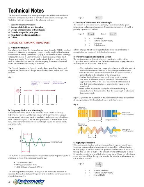
The Acoustic Spectrum in Figure (1) breaks down sound into 3 ranges of<br />
frequencies. The <strong>Ultrasonic</strong> Range is then broken down further into 3 sub<br />
sections.<br />
Fig.1<br />
b. Frequency, Period and Wavelength<br />
<strong>Ultrasonic</strong> vibrations travel in the form of a wave, similar to the way<br />
light travels. However, unlike light waves, which can travel in a vacuum<br />
(empty space), ultrasound requires an elastic medium such as a liquid or a<br />
solid. Shown in Figure (2) are the basic parameters of a continuous wave<br />
(cw). These parameters include the wavelength (l) and the period (T) of a<br />
complete cycle.<br />
Fig. 2<br />
The number of cycles completed in one second is called frequency (f) and is<br />
measured in Hertz (Hz), some examples follow;<br />
• 1 cycle/second= 1Hz<br />
• 1000 cycles/second= 1kHz<br />
• 1,000,000 cycles/second= 1MHz<br />
The time required to complete a full cycle is the period (T), measured in<br />
seconds. The relation between frequency and period in a continuous wave is<br />
given in Equation (1).<br />
40 www.olympusNDT.com<br />
T<br />
Eqn. 1<br />
c. Velocity of Ultrasound and Wavelength<br />
The velocity of ultrasound (c) in a perfectly elastic material at a given<br />
temperature and pressure is constant. The relation between c, f, l and T is<br />
given by Equations (2) and (3):<br />
Eqn. 2 Eqn. 3<br />
l = Wavelength<br />
c = Material Sound Velocity<br />
f = Frequency<br />
T = Period of time<br />
Table 1 on page 48 lists the longitudinal and shear wave velocities of<br />
materials that are commonly tested with ultrasonics.<br />
d. Wave Propagation and Particle Motion<br />
The most common methods of ultrasonic examination utilize either<br />
longitudinal waves or shear waves. Other forms of sound propagation exist,<br />
including surface waves and Lamb waves.<br />
• The longitudinal wave is a compressional wave in which the particle<br />
motion is in the same direction as the propagation of the wave.<br />
• The shear wave is a wave motion in which the particle motion is<br />
perpendicular to the direction of the propagation.<br />
• Surface (Rayleigh) waves have an elliptical particle motion<br />
and travel across the surface of a material. Their velocity is<br />
approximately 90% of the shear wave velocity of the material<br />
and their depth of penetration is approximately equal to one<br />
wavelength.<br />
• Plate (Lamb) waves have a complex vibration occurring in<br />
materials where thickness is less than the wavelength of ultrasound<br />
introduced into it.<br />
Figure (3) provides an illustration of the particle motion versus the direction<br />
of wave propagation for longitudinal waves and shear waves.<br />
Fig. 3<br />
Direction of<br />
Particle Motion<br />
Direction of<br />
Particle Motion<br />
e. Applying Ultrasound<br />
<strong>Ultrasonic</strong> nondestructive testing introduces high frequency sound waves<br />
into a test object to obtain information about the object without altering<br />
or damaging it in any way. Two basic quantities are measured in ultrasonic<br />
testing; they are time of flight or the amount of time for the sound to travel<br />
through the sample, and amplitude of received signal. Based on velocity and<br />
round trip time of flight through the material the material, thickness can be<br />
calculated as follows:<br />
Eqn. 4<br />
Longitudinal Wave<br />
Shear Wave<br />
T = Material Thickness<br />
c = Material Sound Velocity<br />
t = Time of Flight<br />
Direction of<br />
Wave Propagation<br />
Direction of<br />
Wave Propagation


