PUMP RECORD - Senate Judiciary Committee
PUMP RECORD - Senate Judiciary Committee
PUMP RECORD - Senate Judiciary Committee
You also want an ePaper? Increase the reach of your titles
YUMPU automatically turns print PDFs into web optimized ePapers that Google loves.
For<br />
Date<br />
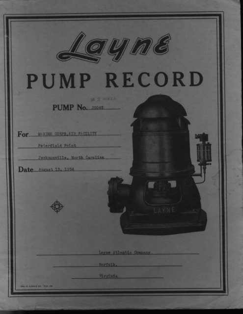
<strong>PUMP</strong> <strong>RECORD</strong><br />
<strong>PUMP</strong> No. 9o<br />
M,RINE CORPS,AIR FACILITY<br />
Peterfield Point<br />
Jacksonville. North Carolina<br />
August 13. 1954<br />
Nor"’olk,<br />
Vlrqnla
Wll Dllt,oa Zn Hm Cmolnm<br />
By-3735, Well #6 tMOHCAJJNA Driller: J. P. Prlne<br />
LOOFWLLFoz U. S. Marine Cor..s Air Facility.. a Peterfield Point, New River<br />
Located t .J..a..c...k.sgn.i.i..1..l in Onslow<br />
Cmty, te North Carolina<br />
Date Drl]Mm Started .J...n.......2._.1..__...7 19 Date Started .J....1...e..o..l..i.......7. 19<br />
m,ah,,a .J...e.._7,.....z...9....Z ,9 h,d ..J..u...Z.y.....)..,.....9...?. Z9<br />
AND Oi<br />
Clay, yellow, hard<br />
nd, _fine,_ graT,__s_of__t<br />
& shells, gray, soft<br />
Streaks of ro.ck & sand_,<br />
gray, soft<br />
Clay, blue, soft<br />
She l_!_roc k, gray_,._ ve_ry__ha_ _rd<br />
Shellrock _gry. hrd<br />
She ii r0c_k gray_s_oft<br />
Soft streaks o__f<br />
fragments from 122 to 200.<br />
’tOTAL<br />
LNN6’ri OW<br />
ALl,<br />
130<br />
135<br />
152<br />
162<br />
168<br />
80 bag:<br />
LI@2’ ole<br />
130<br />
17!<br />
i0[<br />
cem,<br />
4:lmmllll<br />
Sasing<br />
Screen<br />
laming<br />
]creen<br />
OI<br />
8<br />
8<br />
8<br />
Wroug]<br />
Bronm<br />
#rou<br />
Bronm<br />
t iron<br />
ht iron<br />
3asing<br />
-een<br />
8<br />
8<br />
Wroug] t<br />
-Bronx,<br />
iron<br />
]asing 8 Wroug t iron<br />
[ine<br />
1
Data Drg 81re,tad ..J..g....... A, 19.S.7<br />
TO’E.A<br />
O ILL<br />
28 22<br />
9 21<br />
102 53<br />
129 27<br />
i+0 ii<br />
160 6<br />
200 tO<br />
H WELL PANY<br />
8CU OFTlK OB OB<br />
P. Prine<br />
- Bronse’<br />
.o,..<br />
]y, yellow, soft 128 128 Casin8 8 Wrou Iron<br />
Fine ==nd, white, soft 138 IO iScree 8 Bronse<br />
Sh___e!l_ro__ok,_-_L_h_ite s_of _5 12 Casin@ 8 Wrou Iron<br />
nd and streaks of shell- 155 -<br />
S, ,-- -<br />
- s=..
Remarks:<br />
WELL DATA:<br />
19 Static Level<br />
GPM Pumping Level<br />
Permaaest Test<br />
19 7 Static Level 23 ’<br />
GP Active St. I.vd<br />
27’7"<br />
<strong>PUMP</strong> DATA:<br />
8hopNo. Type Lubr.<br />
(’BP to MB)<br />
Column Leith Suetl<br />
Bowl Lenzth Air<br />
Capy and Het Prmmtr,<br />
Hormpower<br />
MOTOR DATA:<br />
Make Frame No.
177’<br />
130’<br />
130 ’<br />
PrImlaa Tst<br />
19 Ltle.<br />
<strong>PUMP</strong> LTA:<br />
Shop No Type Lubr.<br />
DATA:<br />
Vola<br />
Type Cy<br />
Make Frarc, NO.
U<br />
I0’<br />
140’<br />
0’<br />
1o,<br />
!<br />
!<br />
i<br />
i
LAYNE ATLANTIC COMPANY<br />
LOG OF WELL For .M..(..._I..N..E.CQ.PS,<br />
Located at Pe..tsrfiid......PQin in<br />
Date Drilling Sta,ed fu..ly....<br />
Finished Drilling. .A...u...s..t... ?.6.,<br />
NORFOLK, VA.<br />
..I...R.......F:.A...I..:.!.T...y !..Cp L,=.J.:une) Driller: A, -, Imyne<br />
.........................................................<br />
J...a...okson.v.ille County, State ..N.o.r.1h..Caro.!ina<br />
19......5....4...Date Sta,ed .7].y ] ?, 19 5.#.<br />
]9...%4.._ Finished 19 .g<br />
FORMATIONS AND DEPTH OF WELL<br />
DIMENSD NS OF CASING AND ;CREEN<br />
TOTAL<br />
DEPTH<br />
OF ALL<br />
STRATA<br />
44<br />
64<br />
146<br />
15]<br />
154<br />
159<br />
187<br />
08<br />
Surf!<br />
DEPT<br />
OF EA<br />
STRATUM<br />
FT. IN.<br />
II<br />
20,<br />
01 5<br />
2O<br />
5evel<br />
40’ of<br />
PitlCa<br />
Grot<br />
Cement<br />
Depth<br />
4’<br />
FORMATION FOUND AT EACH STRATUM<br />
Their well |<br />
W ell No. I<br />
Fine sandy clay<br />
Fine sand & she].], trace ]mestone<br />
She]lrck, traces of limestone<br />
Shel]rock, fine sand<br />
Coarse she]], sns of clay<br />
Bluo clay<br />
Limestone,(tret)<br />
Soft clay<br />
Limestone, hard<br />
Fine white snd, hacked<br />
Limestone. some fne sand<br />
Limestone<br />
Fine white sand, stroks limestone<br />
TOTAL LENGTH OF[ SPECIFY<br />
LENGTH OF EACH SEC. SCREEN<br />
ALL SCREENS OF SCREEN! OR<br />
and CASINGS OR CASING CASING<br />
FT. IN. FT. IN.I<br />
4 40 Casin.<br />
" ca.|nm commgnces at<br />
134<br />
Casin<br />
1,50<br />
160<br />
169,<br />
184<br />
D-ate Tested<br />
Production<br />
Screen<br />
Casin<br />
Screen<br />
Casinc<br />
Screen<br />
Casin<br />
SIZE OF<br />
OR<br />
CASIN<br />
WELL DATA<br />
Preliminary Test<br />
19c Static Level<br />
GAUGE<br />
OF<br />
SCREEN<br />
;,rface level<br />
Date Tested 9/1<br />
GPM Pumping Level<br />
Permanent Test<br />
954 Static Level i0’<br />
Production 24 GPM Active St. Level<br />
Drawdown 14 Pumping Level 4<br />
Remarks: P4 Hour Test. 24’ Pressure<br />
<strong>PUMP</strong> DATA<br />
Shop No. .o048 Type Lubr.<br />
Type Head TIIS Size Suction<br />
Depth Setting 50’ (Bp to MB)<br />
Size Column 5" X 11/2" X 1" Length Suction<br />
Type Bowl 8"DRIft lngth Air Line<br />
No. Stages 5 Discharge-<br />
Cap’y and Head Pvure<br />
MOTOR DATA<br />
Homepower<br />
, Volt<br />
S!enoid<br />
4"<br />
] 5 Voltage "’,,," 416<br />
I00 Plume 3<br />
SCU Cycles 60<br />
1_._8_,__ Frame No. 3P6p<br />
Cemented in<br />
Opening<br />
verdur<br />
H6 0penin<br />
Evprdur<br />
20’<br />
77’6" of<br />
ra. s<br />
6"
LAYNE ATLANTIC COMPANY<br />
NORFOLK, VA.<br />
LOG OF WELL For .RINE C0P-PS. AIR .FACILITY niller..:..Eliood.Hundl.e<br />
Imcated at Peterfie!d. Point in J...a..ck.on...v...i..1..].e.., County, State..ll..%h...rl.].<br />
Date Drilling Started Jly 29, 19...5..4.....Date Started J.l],y ..1.9, 19....{)..4<br />
Finished Drilling September .4, ]9 54 Finished Q(b r" :19.....4<br />
TOTAL<br />
DEPTH<br />
OF ALL<br />
STRATA<br />
FT. fIN. FT.<br />
0<br />
43 19<br />
64 21<br />
74 10<br />
84<br />
105 21<br />
146 ]7<br />
178 32<br />
195 17<br />
200 5<br />
208 8<br />
Surf<br />
FOR.%IATIONS AND DEPTII OF WELL<br />
DEPTH<br />
OF<br />
STRATUM<br />
To ;al pth<br />
1 4’<br />
Bas’,<br />
Irlne<br />
FORMATION FOUND AT EACH STRATUM<br />
Their well No.<br />
Well No. 2<br />
Surface sand and yellow clay<br />
sand<br />
Mixed clay<br />
Shellrock<br />
Shellrock<br />
Shellrock<br />
Shellrock<br />
Blue clay<br />
BIu clay. some soft shell<br />
Iimeston, hard<br />
Limestone, soft<br />
Hard<br />
soft<br />
Llmesone and stre&ks of sand<br />
SeCt blue clay<br />
and streaks of sand<br />
and streaks of sand<br />
& treaks coarse sand<br />
120<br />
DIMENSIONS OF CASING AND<br />
TOTA<br />
LENGTH OF<br />
ALL SCREENS<br />
and CA811S<br />
FT. IN.<br />
e"asi<br />
136 6<br />
141 5<br />
152 5,<br />
167 15.<br />
l"? 5<br />
1",4 2<br />
LENGTH O| SPECIFY<br />
EACH 8EC. SCREEN<br />
OF SCREEN OR<br />
OR CASING CASING,<br />
FT. IN.<br />
31:<br />
asing<br />
Screen<br />
Screen<br />
Casin<br />
Screen<br />
Casn<br />
Screen<br />
Casin<br />
;CREEN<br />
size O1<br />
CAa<br />
GAUGE<br />
OF<br />
WELL DATA:<br />
Preliminary Test<br />
Date Tested I0.//3 19,54 Static Level 15’ 9"<br />
Production 75 GPM Pumping Level<br />
Permanent Test<br />
l 7<br />
Date Tested 10/4 19 .4 Static Level 16<br />
Production 178 GPM Active St. Level<br />
Drawdown<br />
Remarks:<br />
24 Hour test.<br />
,<br />
Pumping Level 19’<br />
6<br />
emented in<br />
:place<br />
60Fening<br />
Everdur<br />
/’6 Evrdur<br />
Opening<br />
.verdur<br />
80pen%n
0<br />
+IC’<br />
-15’<br />
-20,<br />
-25’<br />
-30’
0<br />
-I0,<br />
-15’<br />
-20,<br />
-25’<br />
TO !ET:GE GRAPH PAPER EUGENE DIETIGEN CO.
54’8"<br />
50’ 0"<br />
418
Derrick<br />
LAYNE VERTICAL CENTRIFUGAL <strong>PUMP</strong><br />
Installation of Layne Pump requires a derrick $e<br />
to 40 feet in height and hand winch or power hoist<br />
of sufficient size to handle the total weight.<br />
Foundation<br />
The concrete foundation for the pump base<br />
should be built in accordance with foundation<br />
plans furnished by the factory. Where e separate pmnp tmse<br />
plate is used it should be set in position in the concrete foundation<br />
before the pump bowls and column installed but not grouted<br />
Into position until the installation is completed.<br />
Dimensions<br />
Check the inside diameter of the well and the<br />
outside diameter of the pump bowls and colof<br />
Well amn flanges couplings to be sure that the<br />
pump and column will go in the well with<br />
ample clearance. The well casing mut be straight and without ohstructions<br />
that might bend the llne shall Measure the static level<br />
of the water in the well to determine if the pump has been furnlshed<br />
with the proper depth of setting. The pump bowls should<br />
be submerged when the pump is operating and do not recommend<br />
guarantee atisfactory operation with a suction flit.<br />
Check<br />
Material<br />
Check all parts of the pump against the packing<br />
llst to find out whether all parts have been rccelved.<br />
If any parts are miIng claim should be made<br />
at once to the raiircad company.<br />
Clean All<br />
All threads and flanged couplings of the discharge<br />
pipe and protective tubing should be carefully<br />
Joints cleaned and at the Ume of installation coeted with<br />
mixture of red lead and shellac. Care should be<br />
taken that there be absolutely sand grit between flanges or<br />
couplings when making up the Joints.<br />
Suction . basket suction is used it should be lowered<br />
into the well first and held by pipe clamps. The<br />
suction pipe ts picked up and screwed into the coupling at top of<br />
basket suction. The basket suction and suction pipe are then lowered<br />
Into the we{ until about 18 inches of sucUon pipe extend above<br />
the well casing. The suction pipe is clamped in this position with<br />
pipe clamps. When the suction pipe has only threads at the top<br />
end should be taken to place the clamps under the small lug<br />
welded the pipe.<br />
Pump Bowls<br />
the pump bowls should be carefully inspected<br />
before placing In the well. Rotate impeller<br />
shaft several times by hand to be sure that it does not bind at<br />
any point. The Impeller shaft should have about 4-tnch or more<br />
end play. DO NOT STRAIN SItAF’I" IN ANY WAY THAT MIGH’r<br />
BEND IT AND DO NOT LIFT <strong>PUMP</strong> BOWLS BY THE SHAFT. The<br />
pump bowls best be handled hy. pair of pipe clamps. The<br />
bowls should be lifted into position and screwed or bolted to the<br />
sucUon pipe. The clamps the suction pipe are then removed<br />
and the bowls and suction pipe lowered into the well until the tp<br />
of the discharge nozzle is about 18 inches above the well casing or<br />
top of foundation. The bowls are then supported at this point by<br />
pipe clamps.<br />
I4i h Check the enclosed chart to determine the<br />
...scxtare.. correct spacing of the spiders in the dis-<br />
Column t’lpe charge column, if the discharge pipe screws<br />
into the pump bowl be sure to have the coupling<br />
at the top end of the first section either with the spider<br />
without the spider as shown the chart. If the lower section of<br />
discharge pipe has a special flange to connect to the pump bowls<br />
be to arrange the pipe with this flange at the lower end.<br />
Protective e shaft ad protective tubing are shipped asembled<br />
in 20-ft. 10-ft. lengths and packed<br />
Tubing with sufficient lubricant to prevent rusting. A<br />
and Shaft<br />
.ft. length 10-ft. length of sha{t and tubing<br />
is required for each 20-ft. 10-ft. length of pipe.<br />
Remove the protecting cap only from the top end of the tubing,<br />
which Is the end fitted with the bronze shaft bearing and tubing<br />
coupling. Slide the assembled tubing and shafting into the discharge<br />
column pipe, making that the bronze bearing end of<br />
the ascenbly wfl.I be top.<br />
Installation of Pump Bowls and Column<br />
Butt Joint Column<br />
Enclosed Line Shaft<br />
Installing Dis- Pull the tubing about six Inches below the<br />
lower end of the discharge pipe and tie<br />
charger Column them together in this position with<br />
piece of rope by taking several half<br />
hitches around the pipe and then the tubing.<br />
Raise the assembled section of pipe, tubing and shafting until<br />
it is hanging vertically in the derrick with the lower end of the<br />
tubing about one inch above board placed the foundation. Remove<br />
the lower plug from the tubing to release the shaft. Raise the<br />
discharge pipe about six inches and take several half hitches<br />
around the shaft. This metimd avoids straining the shaft as the<br />
column is swung under the derrick. Swing the discharge pipe<br />
into position the pump bowls and screw the shaft into the<br />
shaft coupling until it butts aginst the impeller shaft.<br />
THE THREADS AND TIiE ENDS OF THE SHAFTING AND Tile<br />
SHAFT COUPLLNIGS MUST BE PERFECTLY CLEAN.<br />
Lower the discharge pipe and tubing and screw tile tubing onto<br />
the main bearing box about 3 4 threads. Then coat the threads<br />
on the bronze box with the mixture of red lead and shellac and<br />
screw the tubing the box until it butts. The discharge pipe is<br />
then bolted or screwed to the pump bowls.<br />
Remove the clamps from the pump bowls and lower the pump<br />
bowls with the section of discharge column until the column<br />
tends about 18 inches above the well casing or foundation. Clamp<br />
the discharge column in this position.<br />
Remove the bronze shaft bearing and inbing coupling and pour<br />
about one pint of oil into the tubing. The oil used should be<br />
goal grade of mineral oil free from grit and foreign metier, with<br />
viscosity raUng approximately SAE 10 and having relatively<br />
low cold pear point.<br />
When the next section of discharge column is in position in the<br />
derrick replace the bronze bearing, screwing it into the tubing<br />
about 3 or 4 threads. After the spider and spider bushing aIigning<br />
ring have been Installed (as described below) and the shaft<br />
connection is made, lower the discharge pipe and tubing and screw<br />
the tubing onto the bronze bearing about 3 4 threads. Then coat<br />
the threads of the bearing with the rIxture of red lead and shellac<br />
end screw the tubing on the bearing until the ends butt tightly together.<br />
IT IS VERY IMPORTANT THAT EVERY TUBING JOINT<br />
BE TIGHT AND to form seal the ends of the tubing mast be<br />
smooth and square. Wltlle handling and installing the tubing<br />
care to keep from scoring damaging the ends in any way.<br />
When flanged column is used, sllp bronze spider aligning<br />
ring over the top of the tubing and fit It into the recess in the<br />
flange. (Refer to spider spacing chart to determine whether<br />
flange aligning ring should be used at the Joint in qucstlon).<br />
When screw coupled column is used the spider is cast integral with<br />
the coupling. The rubber spider bushings are installed In the<br />
spiders before shipment from the factory.<br />
Each section of discharge column Is installed as described<br />
above. When screw couplings are used care should be taken in<br />
starting the pipe in the coupling. The pipe should start by had<br />
and screw by hand to wlth/n 5 6 threads of butting. If the thread<br />
appears tighter than this check carefully for damaged thread<br />
the pipe should not be forced into the coupling. "lte last 5 6<br />
thrcad should be made up with a chain tong, making sure thst the<br />
|oint /s tight with the pipe butting against the shoulder in the couo..<br />
piing or against the end of the pipe in the coupling as the case<br />
m/ght be.<br />
When the llne shaft connects to the motor drive shaft below the<br />
tension assembly, the motor drive shaft should be attached to the<br />
I/ne shaft in the top scciion of tubing before the top length of discharge<br />
column is installed.<br />
The top length of discharge pipe will usually have special<br />
flange or spectal threads to connect to the bottom of the discharge<br />
ell and the top length of shaft will be of special length.<br />
In case the discharge column doe not check out within reasonable<br />
I/mlts notify the factory to furnish the correct lengths.
INSTRUCTIONS FOR ASSEMBLYING AND DISMANTLING<br />
<strong>PUMP</strong> BOWLS WITH COLLETS<br />
LOCATING TOOL<br />
COLL[.T DRIVER<br />
BU3HING<br />
PELL,F.R<br />
WE,AR RING<br />
NOZZ,LF..<br />
LOCRTING TOOl-<br />
TO ASSEMBLE BOWL<br />
2. Screw locatinq tool into bottom<br />
end of suction nozzle hub.<br />
3. Insert impeller shaft into suction<br />
nozzle bearinq and turn handwheel<br />
of locatinq tool until impeller<br />
shaft is pulled down tight<br />
against the shoulder of the tool.<br />
Place the impeller over the shaft.<br />
Slip the collet over the shaft with<br />
the small end first. (A screw<br />
driver can be used to spread collet<br />
for ease in slipping over shaft).<br />
Hold the impeller firmly into the<br />
wear rinq recess and drive the<br />
collet into place with the male<br />
end of the collet driver.<br />
Remove collet driver and assemble<br />
first intermediate staqe.<br />
Place the next impeller over the<br />
shaft and continue to assemble<br />
as explained above.<br />
When the bowl is completely assembled<br />
remove locatinq tool and<br />
replace cap screw in suction<br />
nozzle.<br />
TO DISMANTLE BOWL<br />
Remove discharge nozzle. Place<br />
collet driver over shaft with the<br />
female end first and while holdinq<br />
the impeller out of the wear<br />
rinq recess, drive the impeller off<br />
of the collet. Remove the collet<br />
and impeller.<br />
Remove the intermediate shell<br />
and drive the impeller off of the<br />
next collet. Continue to dismantle<br />
in like manner,<br />
LMA 83
Screw Coupled Type<br />
8"DR 10"RK<br />
8"RK |0"SK<br />
8"PR<br />
8"SK<br />
BLFJrilNG<br />
BOX<br />
SHAFT<br />
NOZZLE<br />
TOP INTEIEDIATE<br />
BUSHING<br />
RING<br />
Layne Vertical Centrifugal Pump<br />
ENCLOSED LINE SHAFT
SCREW COUPLED DISCHARGE COLUMN<br />
WITH<br />
RUBBER SPIDER BUSHINGS<br />
Printed In U.LA.
Disassemble<br />
and Clean<br />
LAYNE VERTICAL CENTRIFUGAL <strong>PUMP</strong><br />
Installation of Pump Heads mith Butt Joint Stul]ing Box<br />
Hollom Sha/t, Motor lriven<br />
Befo installation, the pump head<br />
should be disassembled and all parts<br />
thoroughly cleaned with kerosene.<br />
move tile stuffing box from the discharge<br />
ell.<br />
Mount u,r;o- he top length of discharge pipe IS<br />
machined with an extra long outside<br />
charge Ell thread the top end and in meat<br />
Is fitted with spec/al adjustable<br />
flange and cast iron paeklng rlug to<br />
fit the ]ottom of the discharge ell. (When 3 casing is used<br />
there Is short piece of pipe with inside and outside threads<br />
which screws on the top length of easing). Screw the cast<br />
iron packing ring down the pteee of pipe far possible.<br />
Clean the face of the adjustable flange and the bottom<br />
flange of the discharge ell and coat with Layncote. Likewise<br />
clean the threads the lop pieee of pipe and the threads<br />
in the adjustable flange discharge ell and paint with<br />
Layneote. Bolt the flange to the discharge ell and/or screw<br />
the discharge ell down on the column pipe to the proper<br />
|ocation so that the packing box be installed and<br />
tightened .to butt Joint connection with the tubing before<br />
]mclung me eH up to ake tens/on. TAKE CARE NOT TO<br />
.PLA..CE .ANY STHAIN ON THE SHAFT as the danger of<br />
.nozng .s. gr.eat, and. any deformation, however slight, wtil<br />
glee trouble In operation.<br />
]lemove the split packing gland<br />
Packing B ox fore insta]llng the packing box.<br />
move the threaded brass bushing<br />
from the bottom of the packing box. Clean the threads on<br />
this bushing, the threads in the packing box, the threhds in<br />
the top end of the tubing and paint with Layneote. Screw<br />
the brass bushing into/he stuffing bo and lower the assembly<br />
Over the drive shaft and screw the bush/ng into the top<br />
end of the tubhag. Use the special wrench furnished and<br />
tighten the Imck/ng box much possible. (The protective<br />
tubing Is made wlth butt Joints throughout from the dicharge<br />
noszle of the bowls to the paeklng box.)<br />
Clean the flanged faees of the discharge eli<br />
and packing box and coat with Layncots.<br />
With the special wrench hold the packing<br />
hog while the dlscharge ell is raised by backing off on the<br />
d/scharge pipe. Paise the discharge ell In this manner until<br />
the packing box and discharge ell flanged faces make tight<br />
Joint and the cap screw holos in the paeklng box match up<br />
/th the tapped holes in the discharge ell. Be sure when the<br />
tightening is complete that the oll cup connection the<br />
Imcklng box is opposite door in the discharge ell. When<br />
automatic solenoid lubricator is used, the oil cup connection<br />
in the packing box should be opposite the side of the discharge<br />
ell having tapped hole to acconmlodate the lubrleatot<br />
bracket. When properly located bolt the packing box<br />
down tighly with the cap screws.<br />
The threaded portion of the discharge eli adjustable<br />
flange is chamfered to receive lamp wick packing. After tans/on<br />
has boeu applied to the assembly, generously fill the<br />
chamfer with lamp wick packing which has been co,tad<br />
with Layncote. Wind the pacldng around the pipe in the proper<br />
direction to tihtan when the packing ring ts screwed<br />
nto place. The packing rio& which is also chamfered, should<br />
then be tlgltened to make a metal to metal Joint with the<br />
discharge ell. The ftl]ing with iamp wick packing of the In-<br />
formed by the chamfers in ell and packing ring is<br />
--tersti..ce<br />
e.ssenu,ai .to inure water tight Joint. The entire pump should<br />
men De towered untLl the discharge eli rests the foundation<br />
built before starting the Installation of the pump.<br />
-lmltt The pump shaft US now be in t<br />
exact center of the pump head and<br />
actly perpendicular to the mahiued<br />
surface of the discharge eli. This can be checked with<br />
a.t.r.night edge, square, and pair of calipers. The discharge<br />
eu can be shifted slightly the concrete foundation or<br />
lted with sh/ma tmt/] the shaft is properly aligned.<br />
PRINTED IN U. 8. A.<br />
Use a good grade of packing and cut enough<br />
-ac.-ns riu, to fnl the packing box to within<br />
the top. Be sure to have each ring long<br />
enough to go around the shaft and butt solidly together.<br />
Each ring of packing should have its Joint placed on the<br />
opposite side of the shaft from the point in the pack/n<br />
underneath. Tamp down each ring of packing as it<br />
stalled and draw down the pack/ng gland Just enough to<br />
put little pressure the packing. After the pump IS<br />
started, draw down on the packing enough to prevent excessive<br />
leakage, but do not make final adjustment of pack-<br />
Ing pressure until the pump has been operated several hours.<br />
Then draw down the packing grand until the leakage is<br />
slight--Just enough to keep the packing moist. The matter<br />
packing is very important and should he watched carefully<br />
for the first few days operation.<br />
When the lubrication of the llne shaft Is by gravity, the<br />
tubing is relieved of pressure at the pump discharge nozzle<br />
and the packing gland should only he drawn sufficiently<br />
tight to prevent dirt from entering the tubing assenbly.<br />
Lower the hollow shaft motor Motor the drive<br />
shaft, talcing not to disturb the alignment.<br />
To insure proper operation of the pump it is<br />
Mount neeessary that the motor be centered exactly,<br />
great care should be taken in this operam.<br />
Bolt motor to discharge ell mot stand with cap screws.<br />
When hollow shaft motor is used the drive shaft<br />
is keyed to removable motor coupling. Screw and<br />
the drive shaft nut, lifting the shaft until the<br />
peuers .are d.rawn against the top of the pump bowl In<br />
pcaiuon me shaft cannot be rotated. The nut should<br />
then he loosened to turn or until the shaft turns freely.<br />
A glb kev is then inserted to prevent the drive shaft nut<br />
from working loose.<br />
rout the discharge eli in position,<br />
Grout Base being careful not to disturb the<br />
and Connect a.ent of the pump head. In case<br />
the discharge nipple is to be connected<br />
to waler main, ]’Car"e Dresser Coup-<br />
]lob should be used. The main should<br />
he placed as nearly possible in<br />
line with the discharge nipple. The Dresser Coupling prevents<br />
throwing any strain on thepump head ff the discharge<br />
nipple and main are not exactly in line.<br />
Connect the hand oil pump, drip<br />
--u---ca..n feed lubricator auto/natic solono/d_<br />
lubricator to the paeklng box.<br />
:o,-o’m<br />
When first connected allow about<br />
one cup full of oil to outer the tubfog.<br />
Then adjust the drip cup automatic lubricator to<br />
allow the following quantity of oll to enter the tub/rig.<br />
F.or sctU.,ng u .to 50 feet-- 5 dros pe.rm<br />
100 feet--lO<br />
150 feet--15 _"<br />
200 feet-l@<br />
300 feet.0<br />
When using a force feed oll pump inject about one cup fuU<br />
of oil for each 24 hours of operaUon.<br />
The oil should be good grade of mineral oil free from<br />
grit..or_foreign matter, with a viscosity rating of approx/mazeJy<br />
s.A.E. 10 and hay/rig relaUvely low cold<br />
Starting<br />
pVum"<br />
C.ECKO. OV .OTOE OTXO<br />
very carefully before applying power. The<br />
pump must operate In a left hand or counter<br />
clook-wise d/rection.<br />
Open pet.oock loci.ted adjacent to pack/rig<br />
box to release air from mscnarge coitunn, and eloec as<br />
as water discharges from pet cock.<br />
After the pump has been in operation a few hours, shut<br />
uowa and check the adjustment of thepump runners. The<br />
pump shaft. .may have been :screwed up fighter by the powe<br />
appUed ana znerey shortened.
PART LIST<br />
Part Name<br />
PaL<br />
. ....<br />
Combination Discharge Ell end<br />
Motor Stand<br />
Head Flange<br />
.._....Head Shaft<br />
Split Packing Gland<br />
Stuffing Box<br />
Stuffing Box Bush<br />
TYPE <strong>PUMP</strong> HEAD<br />
WITH STUFFING BOX<br />
Po.<br />
PART LIST<br />
_._ Packing Ring<br />
_...Discharge Pipe<br />
....].._Tubing<br />
.____ Shaft Coupling<br />
Line Sha[t<br />
Bae Plate<br />
Top Column Flange<br />
MA594B<br />
Part Name<br />
PRINTED IN U. $. A
SOLENOID
Make<br />
11 HP Illl nPM<br />
Frame No.-i<br />
Volts .Ill. Phase<br />
Cycles<br />
NOTICE<br />
To insure prompt service on repairs for<br />
motor B Sure to Furnish the Manufacturer<br />
with the motor Serial Number and Complete<br />
Name Plate Data.<br />
MOTOR<br />
Part No.<br />
MA630<br />
l+,)cking<br />
Atljt,xling<br />
PART LIST<br />
Drive Slmfl Kcy<br />
Part Name<br />
PRINTED


