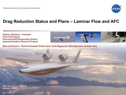
Drag Reduction Status and Plans – Laminar Flow and AFC - NASA
Drag Reduction Status and Plans – Laminar Flow and AFC - NASA
Drag Reduction Status and Plans – Laminar Flow and AFC - NASA

Create successful ePaper yourself
Turn your PDF publications into a flip-book with our unique Google optimized e-Paper software.
National Aeronautics <strong>and</strong> Space Administration<br />
<strong>Drag</strong> <strong>Reduction</strong> <strong>Status</strong> <strong>and</strong> <strong>Plans</strong> <strong>–</strong> <strong>Laminar</strong> <strong>Flow</strong> <strong>and</strong> <strong>AFC</strong><br />
Anthony Washburn - Presenter<br />
Chief Technologist<br />
Environmentally Responsible Aviation<br />
Integrated Systems Research Program<br />
Main Contributors <strong>–</strong> Richard Campbell, William Saric, Israel Wygnanski, Ethan Baumann, Rudolph King<br />
AIAA Aero Sciences Meeting<br />
January 4-7, 2011<br />
www.nasa.gov
Agenda<br />
• Comments on ERA Project <strong>and</strong> <strong>Drag</strong> <strong>Reduction</strong><br />
• Active <strong>Flow</strong> Control Activity<br />
<strong>–</strong> Active <strong>Flow</strong> Control Applied to Rudder<br />
• <strong>Laminar</strong> <strong>Flow</strong> Activities<br />
<strong>–</strong> <strong>Laminar</strong> <strong>Flow</strong> Ground Testing<br />
<strong>–</strong> <strong>Laminar</strong> <strong>Flow</strong> Design Tools<br />
<strong>–</strong> Demonstration of Discrete Roughness for Hybrid <strong>Laminar</strong><br />
<strong>Flow</strong> Control<br />
• Concluding Remarks<br />
2
ERA Technology Portfolio<br />
• Environmentally Responsible Aviation (ERA)<br />
o<br />
o<br />
o<br />
Focused on National Subsonic Transport System Level metrics for<br />
N + 2 timeframe<br />
System research bridging the gap between fundamental (TRL 1-4)<br />
<strong>and</strong> product prototyping (TRL 7) in relevant environments<br />
Innovative technologies for TRL 6 by 2020; critical technologies by<br />
2015<br />
• ERA is two phase project<br />
o<br />
o<br />
2010 <strong>–</strong> 2012 (Phase 1)<br />
•<br />
•<br />
•<br />
2013 <strong>–</strong> 2015 (Phase 2)<br />
•<br />
Investments in broadly applicable technology development<br />
Identify vehicle concepts with potential to meet national goals<br />
High fidelity systems analysis for concept <strong>and</strong> technology trades <strong>and</strong><br />
feasibility<br />
Investments in a few large-scale demonstrations with partners<br />
3
Potential Fuel Burn Improvements<br />
Typical Contributions to <strong>Drag</strong><br />
Merac (ONERA, 2000) <strong>and</strong> Bushnell & Hefner (AGARD 654)<br />
System Assessments<br />
325 Passenger, 4,000 nm<br />
Fuel<br />
Savings<br />
Airframe Wt (-10%) -7%<br />
SFC (-10%) -14%<br />
L/D Cruise (+10%) -13%<br />
Skin Friction (-10%) -9%<br />
Induced <strong>Drag</strong> (-10%) -6%<br />
4
Potential <strong>Drag</strong> <strong>Reduction</strong> Targets<br />
<strong>–</strong> Skin Friction <strong>Drag</strong> <strong>–</strong> <strong>Laminar</strong> <strong>Flow</strong> (LF)<br />
Technologies, Active <strong>Flow</strong> Control (<strong>AFC</strong>) for wetted<br />
area reduction, turbulent drag reduction<br />
<strong>–</strong> Induced <strong>Drag</strong> <strong>–</strong> configuration dominated, increased<br />
aspect ratio, wing tip devices, adaptive trailing edges,<br />
active load alleviation, enabled by lightweight/multifunctional<br />
structures<br />
<strong>–</strong> Interference <strong>Drag</strong> <strong>–</strong> configuration dominated,<br />
propulsion/airframe integration, trim characteristics<br />
<strong>–</strong> Wave <strong>Drag</strong> <strong>–</strong> configuration dominated,<br />
shock/boundary layer interactions, adaptive trailing<br />
edges/compliant structures<br />
<strong>–</strong> Roughness <strong>Drag</strong> <strong>–</strong> joints, fasteners, manufacturing,<br />
operations<br />
Active <strong>and</strong><br />
Passive Concepts<br />
Overcome practical barriers to 50% fuel burn goal through<br />
demonstration of cruise drag reduction by integrated technologies<br />
5
Active <strong>Flow</strong> Control (<strong>AFC</strong>) Applied to Rudder<br />
PI <strong>–</strong> Israel Wygnanski/Edward Whalen<br />
• Use <strong>AFC</strong> on vertical tail to increase on-dem<strong>and</strong><br />
rudder effectiveness<br />
• Most Critical Condition: Vertical tail sized for<br />
engine-out on takeoff<br />
• High thrust engines increase required tail size<br />
• Large tail increases weight <strong>and</strong> cruise drag<br />
• Target: Increase rudder effectiveness with <strong>AFC</strong><br />
• <strong>AFC</strong> used to increase circulation at rudder<br />
deflection angles with natural separation<br />
• More effective rudder yields smaller tail<br />
• <strong>AFC</strong> operates only during take-off <strong>and</strong> l<strong>and</strong>ing<br />
• Critical conditions - 100-150 knots, sideslip ±15°,<br />
rudder ±30°<br />
<strong>Flow</strong> Control Actuators<br />
Sensors<br />
Notional <strong>AFC</strong> Approach<br />
6
<strong>AFC</strong> Technology Maturation<br />
• <strong>AFC</strong> previously demonstrated to enhance<br />
circulation around lifting surfaces<br />
<strong>–</strong> Numerous lab/wind tunnel demonstrations<br />
<strong>–</strong> XV-15 Flight Demonstration<br />
• Use pulsed or periodic actuation to<br />
increase efficiency<br />
Sweeping Jet Actuator Concept<br />
Effect of <strong>AFC</strong> on Wing<br />
7
<strong>AFC</strong> Rudder System Integration Study<br />
Increasing TRL<br />
• <strong>AFC</strong> benefits applied to generic wide-body family<br />
• Conventional planform, chord ratio, single hinged rudder<br />
• Structural approach consistent with modern vertical tails<br />
• Performance requirements/cost benefits for two actuation approaches<br />
evaluated<br />
• Synthetic jets<br />
• Sweeping jets<br />
• Comparison of preventive or corrective use of actuation<br />
• Identify the most critical tail <strong>and</strong> rudder size constraints<br />
• Determine limits of vertical tail size reduction<br />
• <strong>AFC</strong> effectiveness limit<br />
• Other sizing criteria (e.g. cruise stability requirements)<br />
• Generate target size reductions based on known <strong>AFC</strong> effectiveness<br />
<strong>and</strong> sizing criteria<br />
8
<strong>Drag</strong> <strong>Reduction</strong> <strong>–</strong> Active <strong>Flow</strong> Control<br />
Increased On-Dem<strong>and</strong> Rudder Effectiveness with <strong>AFC</strong><br />
• <strong>AFC</strong> system development <strong>–</strong> near term<br />
• <strong>NASA</strong>/Boeing partnership (RPI, Caltech)<br />
• Screen 2 actuators at Caltech Lucas Tunnel <strong>–</strong><br />
Spring 2011<br />
• 1.2m span, 33% rudder, 50° rudder<br />
deflection<br />
• Modular model<br />
• Complimentary CFD/flow field measurements<br />
• <strong>AFC</strong> system development <strong>–</strong> mid term<br />
• Large tunnel test in 2012 with full-scale<br />
actuators<br />
• Testing, simulation, modeling, control<br />
• <strong>AFC</strong> system demonstration<br />
• Flight test in 2013<br />
Active <strong>Flow</strong> Control<br />
Rudder Model<br />
Sweeping<br />
Jets<br />
Synthetic<br />
Jets/Sweeping Jets<br />
Steady<br />
Jets<br />
9
ERA <strong>Laminar</strong> <strong>Flow</strong> Technology Maturation Objectives<br />
System studies require integration of<br />
laminar flow to meet fuel burn goals<br />
<strong>–</strong> Develop <strong>and</strong> demonstrate usable <strong>and</strong> robust<br />
aero design tools for Natural <strong>Laminar</strong> <strong>Flow</strong><br />
(NLF) <strong>and</strong> Hybrid <strong>Laminar</strong> <strong>Flow</strong> Control (HLFC)<br />
• Link transition prediction to high-fidelity aero design<br />
tools<br />
<strong>–</strong> Explore the limits of CF control through<br />
Discrete Roughness Elements (DRE)<br />
• Practical Mach, Re demonstration at relevant C L<br />
• Potential control to relax surface quality<br />
requirements<br />
<strong>–</strong> Seek opportunities for integration of NLF,<br />
HLFC, <strong>and</strong>/or DRE into flight weight systems<br />
• Underst<strong>and</strong> system trades through demonstration<br />
<strong>–</strong> Assess <strong>and</strong> develop high Reynolds number<br />
ground test capability<br />
Analysis compared<br />
to NTF data with<br />
NLF<br />
flow<br />
delay<br />
Re = 6.7M<br />
DRE effect, low M, low Rn<br />
1<br />
0
Design of <strong>Laminar</strong> <strong>Flow</strong> Wings<br />
• <strong>Laminar</strong> flow approach is dependent on system requirements <strong>and</strong><br />
trades<br />
<strong>–</strong> Mach/Sweep, Re, Cp distribution, high-lift system, stability <strong>and</strong> control<br />
<strong>–</strong> Aircraft components <strong>and</strong> laminar extent of each<br />
<strong>–</strong> Swept-wing laminar flow is design tradeoff between Tollmien<strong>–</strong>Schlichting <strong>and</strong><br />
Crossflow transition modes<br />
• Challenges<br />
<strong>–</strong> Required favorable pressure gradient <strong>and</strong> sweep limitations can increase<br />
wave drag for transonic design <strong>–</strong> counter with thinner airfoil<br />
<strong>–</strong> Multi-point design complicated by need to consider loss of NLF<br />
<strong>–</strong> Leading edge radius limit <strong>and</strong> restrictions on leading edge high-lift devices can<br />
impact low-speed performance<br />
<strong>–</strong> Manufacturing <strong>and</strong> maintenance tolerances tighter (surface finish, steps, gaps,<br />
design/operation affected by loss of NLF in flight (insects, ice)<br />
<strong>–</strong> Ground testing at flight Reynolds numbers currently not practical<br />
11
Ground Facility Capability for <strong>Laminar</strong> <strong>Flow</strong> Testing<br />
PI <strong>–</strong> Rudolph King<br />
• Boeing/<strong>NASA</strong> test in <strong>NASA</strong> National Transonic<br />
Facility (NTF) at High Re (AIAA 2010-1302)<br />
• M = 0.8, 25° leading edge sweep design for laminar<br />
flow with mix of TS <strong>and</strong> CF transition at Re between<br />
11 <strong>–</strong> 22 million<br />
<strong>–</strong> Designed with non-linear full potential equations with<br />
coupled integral boundary layer code<br />
<strong>–</strong> Instability growth <strong>and</strong> transition prediction calculations by<br />
compressible linear stability code<br />
• <strong>Laminar</strong> flow lost at higher Re numbers<br />
<strong>–</strong> Turbulent wedges emanating from leading edge of wing<br />
<strong>–</strong> Suspect attachment line contamination from particles,<br />
frost, <strong>and</strong>/or oil<br />
• Spring 2011 flow quality survey in cryo conditions<br />
Analysis compared to NTF transition<br />
measurements at Re = 22 M/ft<br />
Cp distribution for CF<br />
dominated region<br />
Cp distribution for TS<br />
dominated region<br />
NLF model in NTF<br />
12
Aero Design Tools for <strong>Laminar</strong> <strong>Flow</strong><br />
PI <strong>–</strong> Richard Campbell<br />
• Approach to NLF Design with CFD<br />
<strong>–</strong> Develop multi-fidelity boundary layer transition prediction<br />
capability <strong>and</strong> couple with an advanced CFD flow solver<br />
<strong>–</strong> Develop a robust multipoint NLF design strategy <strong>and</strong><br />
implement in the CDISC knowledge-based design method<br />
<strong>–</strong> Validate the design approach using wind tunnel test results<br />
<strong>and</strong>/or high-fidelity boundary layer stability analysis<br />
13
Multi-Fidelity Transition Prediction Capability<br />
• USM3D flow solver selected for 3-D method development<br />
<strong>–</strong> solves Navier-Stokes equations on unstructured grid using cell-centered, upwind<br />
method<br />
<strong>–</strong> Recent modifications allow specification of boundary layer transition location for<br />
Spalart-Allmaras <strong>and</strong> various 2-equation turbulence models, includes<br />
approximation to transition region to reduce abrupt changes in flow<br />
• C<strong>and</strong>idate transition prediction modules for various fidelity levels<br />
Low MOUSETRAP (<strong>NASA</strong>)<br />
Medium MATTC (<strong>NASA</strong>)<br />
Medium RATTraP (Lockheed/AFRL)<br />
High LASTRAC (<strong>NASA</strong>)<br />
• Currently, MOUSETRAP <strong>and</strong> MATTC have been linked with USM3D using<br />
a Linux script to provide an initial automated 3-D transition prediction<br />
capability<br />
14
US n25 airfoil<br />
MATTC Transition Prediction Method<br />
• Modal Amplitude Tracking <strong>and</strong> Transition Computation<br />
• Computes transition location based on empirical correlations<br />
<strong>–</strong> transition studies using 3 airfoils run in MSES <strong>and</strong> LASTRAC<br />
<strong>–</strong> TS: Re = 0.25 - 30 million<br />
<strong>–</strong> CF: Re = 10 - 30 million, sweep = 10 - 30 degrees<br />
• x tr = f(Re,dCp/dx,x), with sweep included for CF<br />
• No boundary layer information required, provides n-factor envelope<br />
15<br />
15
US n25 airfoil<br />
Comparison of MATTC/USM3D Results with Wind<br />
Tunnel <strong>and</strong> other CFD Results<br />
MATTC<br />
LST (WORST CASE)<br />
LST (BEST CASE)<br />
EXPERIMENT<br />
Experimental<br />
transition front<br />
16
“Knowledge-Based” NLF Airfoil Design with CDISC<br />
NLFCP Constraint<br />
•<br />
•<br />
•<br />
•<br />
Specified transition<br />
location (NF=9)<br />
Airfoil designs <strong>–</strong> note tight tolerance<br />
<strong>Laminar</strong> bucket<br />
New knowledge-based approach for design to a specified TS N-factor distribution<br />
<strong>Laminar</strong> “drag bucket” characteristics can be related to the N-factor family<br />
exponent (NFE)<br />
New approach compatible with other CDISC design method flow <strong>and</strong> geometry<br />
constraints for practical 3-D design<br />
Independent analysis by Streit at DLR using Schrauf’s LILO method confirmed TS<br />
results <strong>and</strong> indicated robust CF performance<br />
17
Hybrid <strong>Laminar</strong> <strong>Flow</strong> Control with Discrete Roughness<br />
PI <strong>–</strong> William Saric<br />
Crossflow transition delay possible on swept wing<br />
•<br />
•<br />
Judiciously designed Cp distribution<br />
Passive, spanwise periodic Discrete<br />
Roughness Elements (DRE) near attachment<br />
line (Saric et al. 1998)<br />
<strong>–</strong><br />
<strong>–</strong><br />
<strong>–</strong><br />
<strong>–</strong><br />
controls growth of spanwise periodic crossflow<br />
instability<br />
Introduces weakly growing wavelength at half<br />
most amplified wavelength through stability<br />
analysis<br />
modified mean flow is stable to all greater<br />
wavelengths<br />
Restricts TS waves due to more stable 3D wave<br />
18
Flight Demonstration of DRE<br />
• DRE technology previously demonstrated in flight (Saric et al.<br />
2010; Rhodes et al. 2010)<br />
<strong>–</strong> chord Re c = 7.5M<br />
<strong>–</strong> 30° swept wing<br />
• ERA Goal: Demonstrate DRE on <strong>NASA</strong> DFRC G-III SubsoniC<br />
Research AircrafT (SCRAT)<br />
<strong>–</strong> Re c characteristic of transport aircraft (up to 30 million)<br />
<strong>–</strong> Relevant wing loading (section C l ≥ 0.5)<br />
<strong>–</strong> Mach range from 0.66 to 0.76<br />
<strong>–</strong> Nominal cruise for host aircraft (around 3.5° - 4.0°)<br />
19
SARGE Wing Glove Layout <strong>and</strong> Objectives<br />
• SARGE is an instrumented wing glove designed to demonstrate hybrid<br />
laminar flow control on both the pressure <strong>and</strong> suction sides of the glove<br />
• Primary Goal:<br />
<strong>–</strong> At Rec up to 22 million, SARGE will demonstrate natural laminar flow (NLF) to<br />
60% x/c (glove chord) on the suction side <strong>and</strong> 50% x/c on the pressure side<br />
<strong>–</strong> At Rec ≥ 22 million, DREs will be used to increase laminar flow on the suction<br />
side by at least 50% (e.g. if natural transition occurs at 40% x/c, DREs will be<br />
used to delay transition to 60% x/c)<br />
• Secondary Goal: Demonstrate ability of DRE overcome surface quality<br />
on leading edge by textured paint finishes<br />
20
SARGE Glove Design Cycle<br />
Design philosophy<br />
<strong>–</strong> t/c <strong>and</strong> CL are design points<br />
<strong>–</strong> Design pressure minimum as far aft as possible<br />
• Subcritical to TS instability<br />
• Restrict leading edge radius to R θ
SARGE Glove Design <strong>Status</strong><br />
Pressure distribution near C l of 0.5, M = 0.75, H = 41300 ft, AoA = 3.3°<br />
<strong>Laminar</strong> <strong>Flow</strong> Glove<br />
Wing<br />
22
SARGE Flight Envelope<br />
• Experiment will demonstrate hybrid laminar flow control over a wide range of<br />
Mach <strong>and</strong> Re c<br />
<strong>–</strong> mid-span Re c = 17 <strong>–</strong> 22M for NLF, <strong>and</strong> Re c = 22 <strong>–</strong> 27.5M for DRE control<br />
23
Partners in ERA <strong>Drag</strong> <strong>Reduction</strong> Activities<br />
• Texas A&M University - William Saric, Helen Reed, Joseph Kuehl, Michael<br />
Belisle, Matthew Roberts, Aaron Tucker, Matthew Tufts, Thomas Williams<br />
• Boeing Research <strong>and</strong> Technology - Edward Whalen, Arvin Smilovich<br />
• Boeing Commercial Airplanes - Doug Lacy, Mary Sutanto, Jeffrey Crouch<br />
• Rensselaer Polytechnic Institute - Miki Amitay, Helen Mooney, Sarah Zaremski<br />
<strong>and</strong> Glenn Saunders<br />
• California Institute of Technology - Mory Gharib, Roman Seele<br />
• Iowa State - Richard Wlezien<br />
• Air Force Research Lab - Gary Dale<br />
• Relevant Papers at 2011 AIAA Applied Aero Conference<br />
• Progress Toward Efficient <strong>Laminar</strong> <strong>Flow</strong> Analysis <strong>and</strong> Design, R. L. Campbell, M. L.<br />
Campbell, T. Streit<br />
• Design of the Subsonic Aircraft Roughness Glove Experiment (SARGE), M.J.<br />
Belisle, M.W. Roberts, M.W. Tufts, A.A. Tucker, T. Williams, W.S. Saric, H.L. Reed<br />
• Computational Analysis of the G-III <strong>Laminar</strong> <strong>Flow</strong> Glove, M. Malik, W. Liao, E. Lee-<br />
Rausch, F. Li, M. Choudhari, C-L Chang<br />
24
Concluding Remarks<br />
• ERA Project <strong>Drag</strong> <strong>Reduction</strong> Investments<br />
<strong>–</strong> Phase 1 - broadly applicable viscous drag reduction technologies<br />
<strong>–</strong><br />
Phase 2 <strong>–</strong> Select a few large scale demonstrations including drag<br />
reduction technologies<br />
• Address critical barriers to practical laminar flow<br />
<strong>–</strong> Design <strong>and</strong> Integration<br />
<strong>–</strong> Surface tolerances, steps, <strong>and</strong> gaps<br />
<strong>–</strong> Maintenance <strong>and</strong> operations <strong>–</strong> ice, insects, etc.<br />
• Demonstrate feasibility of Discrete Roughness Elements<br />
(DRE) as form of hybrid laminar flow control for swept wings<br />
25