GlobalTop-Gmm-g3 Datasheet-V0C.pdf - FTP Directory Listing
GlobalTop-Gmm-g3 Datasheet-V0C.pdf - FTP Directory Listing
GlobalTop-Gmm-g3 Datasheet-V0C.pdf - FTP Directory Listing

You also want an ePaper? Increase the reach of your titles
YUMPU automatically turns print PDFs into web optimized ePapers that Google loves.
Data Sheet<br />
<strong>GlobalTop</strong> Technology Inc.<br />
<strong>Gmm</strong>-<strong>g3</strong><br />
GNSS Module<br />
Data Sheet<br />
Revision: <strong>V0C</strong><br />
The <strong>Gmm</strong>-<strong>g3</strong> is a 5 th generation stand-alone GPS module with lightning fast TTFF, ultra high sensitivity<br />
(-165dBm), and exceptional low power consumption in a small form factor (11.5*13*2.1mm)<br />
This document is the exclusive property of <strong>GlobalTop</strong> Tech Inc. and should not be distributed, reproduced, into any other format without prior<br />
permission of <strong>GlobalTop</strong> Tech Inc. Specifications subject to change without prior notice.<br />
Copyright © 2011 <strong>GlobalTop</strong> Technology Inc. All Rights Reserved.<br />
No.16 Nan-ke 9 th Rd, Science-Based Industrial Park, Tainan, 741, Taiwan, R.O.C.<br />
Tel: +886-6-5051268 / Fax: +886-6-5053381 / Email: sales@gtop-tech.com / Web: www.gtop-tech.com
<strong>GlobalTop</strong> Technology<br />
<strong>Gmm</strong>-<strong>g3</strong> Data Sheet<br />
Version History<br />
Title: <strong>GlobalTop</strong> <strong>Gmm</strong>-<strong>g3</strong> <strong>Datasheet</strong><br />
Subtitle: GPS Module<br />
Doc Type: <strong>Datasheet</strong><br />
Revision Date Author Description<br />
V0A 2012/5/10 Delano Preliminary<br />
V0B 2012/8/13 Delano<br />
Release<br />
Add power Consumption<br />
Remove Acceleration Accuracy<br />
Add GLONASS NMEA Protocol<br />
<strong>V0C</strong> 2012/9/5 Delano Update module photo<br />
Document #<br />
Ver. <strong>V0C</strong><br />
This document is the exclusive property of <strong>GlobalTop</strong> Tech Inc. and should not be distributed, reproduced, into any other format without<br />
prior permission of <strong>GlobalTop</strong> Tech Inc. Specifications subject to change without prior notice.<br />
Copyright © 2011 <strong>GlobalTop</strong> Technology Inc. All Rights Reserved.<br />
2
<strong>GlobalTop</strong> Technology<br />
<strong>Gmm</strong>-<strong>g3</strong> Data Sheet<br />
Table of Contents<br />
Document #<br />
Ver. <strong>V0C</strong><br />
1. Functional Description ........................................................................................................... 4<br />
1.1 Overview ....................................................................................................................... 4<br />
1.2 Highlights and Features ................................................................................................ 5<br />
1.3 System Block Diagram ................................................................................................... 6<br />
1.4 Multi-tone active interference canceller ...................................................................... 7<br />
1.5 1PPS .............................................................................................................................. 7<br />
1.6 AGPS Support for Fast TTFF (EPO) ............................................................................. 7<br />
1.7 EASY ........................................................................................................................... 7<br />
1.8 AlwaysLocate (Advance Power Periodic Mode) ......................................................... 9<br />
1.9 Embedded Logger function .......................................................................................... 9<br />
2. Specifications ....................................................................................................................... 10<br />
2.1 Mechanical Dimension ............................................................................................... 10<br />
2.2 Recommended PCB pad Layout .................................................................................. 11<br />
2.3 Pin Configuration ........................................................................................................ 12<br />
2.4 Pin Assignment ........................................................................................................... 12<br />
2.5 Description of I/O Pin ................................................................................................. 13<br />
2.6 Specification List ......................................................................................................... 15<br />
2.7 Absolute Maximum Ratings ........................................................................................ 16<br />
2.8 Operating Conditions .................................................................................................. 16<br />
2.9 GPS External Antenna Specification (Recommended) ............................................... 16<br />
3. Protocols .............................................................................................................................. 17<br />
3.1 NMEA Output Sentences ............................................................................................ 17<br />
3.2 MTK NMEA Command Protocols ................................................................................ 23<br />
3.3 Firmware Customization Services ............................................................................... 24<br />
4. Reference Design .................................................................................................................. 25<br />
4.1 Patch (Passive) Antenna .............................................................................................. 25<br />
4.2 Active Antenna ............................................................................................................ 26<br />
5. Packing and Handling ............................................................................................................ 27<br />
5.1 Moisture Sensitivity .................................................................................................... 27<br />
5.2 Packing ........................................................................................................................ 28<br />
5.3 Storage and Floor Life Guideline ................................................................................. 30<br />
5.4 Drying .......................................................................................................................... 30<br />
5.5 ESD Handling ............................................................................................................... 31<br />
6. Reflow Soldering Temperature Profile ................................................................................... 32<br />
6.1 SMT Reflow Soldering Temperature Profile ................................................................ 32<br />
6.2 Manual Soldering ........................................................................................................ 36<br />
7. Contact Information .............................................................................................................. 37<br />
This document is the exclusive property of <strong>GlobalTop</strong> Tech Inc. and should not be distributed, reproduced, into any other format without<br />
prior permission of <strong>GlobalTop</strong> Tech Inc. Specifications subject to change without prior notice.<br />
Copyright © 2011 <strong>GlobalTop</strong> Technology Inc. All Rights Reserved.<br />
3
<strong>GlobalTop</strong> Technology<br />
<strong>Gmm</strong>-<strong>g3</strong> Data Sheet<br />
1. Functional Description<br />
1.1 Overview<br />
Document #<br />
Ver. <strong>V0C</strong><br />
The <strong>GlobalTop</strong> <strong>Gmm</strong>-<strong>g3</strong> module utilizes the MediaTek new generation GNSS Chipset MT3333 that<br />
support various location and navigation applications, including autonomous GPS, GLONASS,<br />
GALILEO(on request), QZSS, SBAS(note) ranging (WAAS, EGNOS, GAGAN, MSAS),QZSS,DGPS(RTCM)<br />
and AGPS. It support up to 210 PRN channels with 99 search channels and 33 simultaneous<br />
tracking channels.<br />
It is the industry’s highest level of sensitivity (-165dBm) and instant Time-to-First Fix (TTFF).<br />
Precise GNSS signal processing give the ultra-precise positioning under low receptive, high velocity<br />
conditions. Up to 12 multi-tone active interference canceller (ISSCC2011 award), customer can<br />
have more flexibility in system design.<br />
Power management design makes <strong>Gmm</strong>-<strong>g3</strong> easily integrated into your system without extra<br />
voltage regulator. <strong>Gmm</strong>-<strong>g3</strong> allows direct battery connection, no need any external LDO and gives<br />
customers plenty of choices for their application circuit.<br />
The excellent low power consumption of <strong>Gmm</strong>-<strong>g3</strong> make it easier to applied to power sensitive<br />
devices, especially portable applications, need not worry about operating time anymore and user<br />
can get more fun.<br />
It also combined with many advanced features including AlwaysLocate, EASY, EPO, and<br />
logger function.<br />
Application:<br />
Handheld Device<br />
Tablet PC/PLB/MID<br />
M2M application<br />
Asset management<br />
Security industry<br />
Surveillance<br />
This document is the exclusive property of <strong>GlobalTop</strong> Tech Inc. and should not be distributed, reproduced, into any other format without<br />
prior permission of <strong>GlobalTop</strong> Tech Inc. Specifications subject to change without prior notice.<br />
Copyright © 2011 <strong>GlobalTop</strong> Technology Inc. All Rights Reserved.<br />
4
<strong>GlobalTop</strong> Technology<br />
<strong>Gmm</strong>-<strong>g3</strong> Data Sheet<br />
1.2 Highlights and Features<br />
33 tracking/ 99 acquisition-channel GPS/GLONASS/GALILEO receiver<br />
Supports QZSS, SBAS(WAAS, EGNOS, GAGAN, MSAS) ranging<br />
Ultra-High Sensitivity: -165dBm<br />
High Update Rate: up to 10Hz<br />
(note1)<br />
12 multi-tone active interference canceller<br />
(note2)<br />
[ISSCC 2011 Award -Section 26.5]<br />
(http://isscc.org/doc/2011/isscc2011.advanceprogrambooklet_abstracts.<strong>pdf</strong> )<br />
High accuracy 1-PPS timing support for Timing Applications (±10ns jitter)<br />
AGPS Support for Fast TTFF (EPO Enable 7 days/14 days )<br />
EASY (note2)<br />
: Self-Generated Orbit Prediction for instant positioning fix<br />
AlwaysLocate<br />
(note2)<br />
Logger function Embedded<br />
Document #<br />
Ver. <strong>V0C</strong><br />
Intelligent Algorithm (Advance Power Periodic Mode) for power saving<br />
(note2)<br />
Gtop Firmware Customization Services<br />
GPS+GLONASS Consumption current(@3.3V):<br />
• Acquisition: 35mA Typical<br />
• Tracking: 29mA Typical<br />
E911, RoHS, REACH compliant<br />
CE, FCC Certification<br />
Note 1: SBAS can only be enabled when update rate is less than or equal to 5Hz.<br />
Note2: Some features need special firmware or command programmed by customer, please<br />
refer to G-top documents “PMTK command List” and “Firmware check list_C39”.<br />
This document is the exclusive property of <strong>GlobalTop</strong> Tech Inc. and should not be distributed, reproduced, into any other format without<br />
prior permission of <strong>GlobalTop</strong> Tech Inc. Specifications subject to change without prior notice.<br />
Copyright © 2011 <strong>GlobalTop</strong> Technology Inc. All Rights Reserved.<br />
5
<strong>GlobalTop</strong> Technology<br />
<strong>Gmm</strong>-<strong>g3</strong> Data Sheet<br />
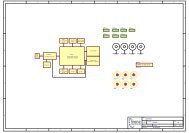
1.3 System Block Diagram<br />
VCC<br />
VBACKUP 14<br />
GPS Single Chipset<br />
Document #<br />
Ver. <strong>V0C</strong><br />
9<br />
1 1PPS<br />
Antenna_IN<br />
LNA SAW Filter<br />
13<br />
3D_FIX<br />
VANT<br />
NRESET<br />
3<br />
16<br />
7<br />
2,4,8,10,15<br />
32.768KHz<br />
Crystal<br />
16.368MHz<br />
TCXO<br />
11<br />
TXDA<br />
12<br />
RXDA<br />
This document is the exclusive property of <strong>GlobalTop</strong> Tech Inc. and should not be distributed, reproduced, into any other format without<br />
prior permission of <strong>GlobalTop</strong> Tech Inc. Specifications subject to change without prior notice.<br />
Copyright © 2011 <strong>GlobalTop</strong> Technology Inc. All Rights Reserved.<br />
5<br />
6<br />
TXDB<br />
RXDB<br />
6
<strong>GlobalTop</strong> Technology<br />
<strong>Gmm</strong>-<strong>g3</strong> Data Sheet<br />
1.4 Multi-tone active interference canceller<br />
Document #<br />
Ver. <strong>V0C</strong><br />
Because different application (Wi-Fi , GSM/GPRS,3G/4G,Bluetooth )are integrated into navigation<br />
system , the harmonic of RF signal will influence the GPS reception , The multi-tone active<br />
interference canceller (abbr: MTAIC ) can reject external RF interference which come from other<br />
active components on the main board , to improve the capacity of GPS reception without any<br />
needed HW change in the design .<strong>Gmm</strong>-<strong>g3</strong> can cancel up to 12 independent channel interference<br />
continuous wave (CW)<br />
1.5 1PPS<br />
A pulse per second (1 PPS) is an electrical signal that very precisely indicates the start of a second.<br />
Depending on the source, properly operating PPS signals have an accuracy ranging ±10ns.<br />
1 PPS signals are used for precise timekeeping and time measurement. One increasingly common<br />
use is in computer timekeeping, including the NTP protocol. A common use for the PPS signal is to<br />
connect it to a PC using a low-latency, low-jitter wire connection and allow a program to synchronize<br />
to it:<br />
<strong>Gmm</strong>-<strong>g3</strong> supplies the high accurate 1PPS timing to synchronize to GPS time after 3D-Fix.<br />
A power-on output 1pps is also available for customization firmware settings.<br />
1.6 AGPS Support for Fast TTFF (EPO)<br />
The AGPS (EPO) supply the predicated Extended Prediction Orbit data to speed TTFF ,users can<br />
download the EPO data to GPS engine from the <strong>FTP</strong> server by internet or wireless network ,the GPS<br />
engine will use the EPO data to assist position calculation when the navigation information of<br />
satellites are not enough or weak signal zone . About the detail, please link Gtop website .<br />
1.7 EASY<br />
The EASY is embedded assist system for quick positioning, the GPS engine will calculate and predict<br />
automatically the single emperies ( Max. up to 3 days )when power on ,and save the predict<br />
information into the memory , GPS engine will use these information for positioning if no enough<br />
information from satellites , so the function will be helpful for positioning and TTFF improvement<br />
under indoor or urban condition , the Backup power (VBACKUP) is necessary .<br />
This document is the exclusive property of <strong>GlobalTop</strong> Tech Inc. and should not be distributed, reproduced, into any other format without<br />
prior permission of <strong>GlobalTop</strong> Tech Inc. Specifications subject to change without prior notice.<br />
Copyright © 2011 <strong>GlobalTop</strong> Technology Inc. All Rights Reserved.<br />
7
<strong>GlobalTop</strong> Technology<br />
<strong>Gmm</strong>-<strong>g3</strong> Data Sheet<br />
Figure 1.12-1 EASY System operation<br />
Document #<br />
Ver. <strong>V0C</strong><br />
Please refer to the Fig 1.12-1, When GPS device great the satellite information from GPS satellites,<br />
the GPS engine automatically pre-calculate the predict orbit information for 3 days<br />
The GPS device still can quickly do the positioning with EASY function under weak GPS signal.<br />
This document is the exclusive property of <strong>GlobalTop</strong> Tech Inc. and should not be distributed, reproduced, into any other format without<br />
prior permission of <strong>GlobalTop</strong> Tech Inc. Specifications subject to change without prior notice.<br />
Copyright © 2011 <strong>GlobalTop</strong> Technology Inc. All Rights Reserved.<br />
8
<strong>GlobalTop</strong> Technology<br />
<strong>Gmm</strong>-<strong>g3</strong> Data Sheet<br />
1.8 AlwaysLocate (Advance Power Periodic Mode)<br />
Document #<br />
Ver. <strong>V0C</strong><br />
Embedded need to be executed full y all the time , the algorithm can be set by different necessary to<br />
decide the operation level of GPS function , reduce power consumption , it will suffer positing<br />
accuracy to get the target of power saving and extend the usage time of product . (The positioning<br />
accuracy of reporting location < 50m (CEP).)<br />
1.9 Embedded Logger function<br />
The Embedded Logger function don’t need host CPU (MCU ) and external flash to handle the<br />
operation , GPS Engine will use internal flash (embedded in GPS chipset ) to log the GPS data (Data<br />
format : UTC, Latitude , longitude, Valid ,Checksum ), the max log days can up to 2 days under<br />
Note<br />
AlwaysLocate condition .<br />
Note: Data size per log was shrunk from 24 bytes to 15 bytes.<br />
This document is the exclusive property of <strong>GlobalTop</strong> Tech Inc. and should not be distributed, reproduced, into any other format without<br />
prior permission of <strong>GlobalTop</strong> Tech Inc. Specifications subject to change without prior notice.<br />
Copyright © 2011 <strong>GlobalTop</strong> Technology Inc. All Rights Reserved.<br />
9
<strong>GlobalTop</strong> Technology<br />
<strong>Gmm</strong>-<strong>g3</strong> Data Sheet<br />
2. Specifications<br />
2.1 Mechanical Dimension<br />
Dimension: (Unit: mm, Tolerance: +/- 0.2mm)<br />
Document #<br />
Ver. <strong>V0C</strong><br />
This document is the exclusive property of <strong>GlobalTop</strong> Tech Inc. and should not be distributed, reproduced, into any other format without<br />
prior permission of <strong>GlobalTop</strong> Tech Inc. Specifications subject to change without prior notice.<br />
Copyright © 2011 <strong>GlobalTop</strong> Technology Inc. All Rights Reserved.<br />
10
<strong>GlobalTop</strong> Technology<br />
<strong>Gmm</strong>-<strong>g3</strong> Data Sheet<br />
2.2 Recommended PCB pad Layout<br />
(Unit: mm, Tolerance: 0.1mm)<br />
(Top view)<br />
Document #<br />
Ver. <strong>V0C</strong><br />
This document is the exclusive property of <strong>GlobalTop</strong> Tech Inc. and should not be distributed, reproduced, into any other format without<br />
prior permission of <strong>GlobalTop</strong> Tech Inc. Specifications subject to change without prior notice.<br />
Copyright © 2011 <strong>GlobalTop</strong> Technology Inc. All Rights Reserved.<br />
11
<strong>GlobalTop</strong> Technology<br />
<strong>Gmm</strong>-<strong>g3</strong> Data Sheet<br />
2.3 Pin Configuration<br />
2.4 Pin Assignment<br />
(Top view)<br />
Document #<br />
Ver. <strong>V0C</strong><br />
Pin Name I/O Description & Note<br />
1 Antenna_IN I Antenna Signal Input<br />
2 GND p Ground<br />
3 VANT PI External Antenna power input<br />
4 GND P Ground<br />
5 TXDB O Serial Data Output<br />
6 RXDB I Serial Data Input for DGPS RTCM data streaming<br />
7 NRESET I Reset Input, Low Active<br />
8 GND P Ground<br />
9 1PPS O 1PPS Time Mark Output 2.8V CMOS Level<br />
10 GND P Ground<br />
11 TXDA O Serial Data Output A for NMEA output (TTL)<br />
12 RXDA I Serial Data Input A for Firmware update (TTL)<br />
13 3D_FIX O 3D-Fix Indicator<br />
14 VBACKUP PI Backup power input for RTC & navigation data keep<br />
15 GND P Ground<br />
16 VCC PI Main DC power input<br />
This document is the exclusive property of <strong>GlobalTop</strong> Tech Inc. and should not be distributed, reproduced, into any other format without<br />
prior permission of <strong>GlobalTop</strong> Tech Inc. Specifications subject to change without prior notice.<br />
Copyright © 2011 <strong>GlobalTop</strong> Technology Inc. All Rights Reserved.<br />
12
<strong>GlobalTop</strong> Technology<br />
<strong>Gmm</strong>-<strong>g3</strong> Data Sheet<br />
2.5 Description of I/O Pin<br />
Antenna_IN, Pin1<br />
Document #<br />
Ver. <strong>V0C</strong><br />
This is the GNSS RF signal input pin, which can be connected to a passive antenna or an active<br />
antenna.<br />
GND, Pin2, Pin4, Pin8, Pin10, Pin15<br />
Ground<br />
VANT, Pin3<br />
The power supply input for external active antenna. The input voltage should be kept from 2.5V to<br />
5V.<br />
TXDB, Pin5<br />
This is the UART transmitter of the module. It is used for customization by firmware. If not used,<br />
keep floating.<br />
RXDB, Pin6<br />
This pin receive DGPS data of RTCM protocol (TTL level), if not used keep floating<br />
NRESET, Pin7<br />
Low active, it causes the module to reset. If not used, keep floating.<br />
1PPS, Pin9<br />
This pin provides one pulse-per-second output from the module and synchronizes to GPS time.<br />
Keep floating if not used.<br />
TXDA, Pin11<br />
This is the UART-A transmitter of the module. It outputs GPS information for application.<br />
This document is the exclusive property of <strong>GlobalTop</strong> Tech Inc. and should not be distributed, reproduced, into any other format without<br />
prior permission of <strong>GlobalTop</strong> Tech Inc. Specifications subject to change without prior notice.<br />
Copyright © 2011 <strong>GlobalTop</strong> Technology Inc. All Rights Reserved.<br />
13
<strong>GlobalTop</strong> Technology<br />
<strong>Gmm</strong>-<strong>g3</strong> Data Sheet<br />
RXDA, Pin12<br />
This is the UART-A receiver of the module. It is used to receive commands from system.<br />
3D_FIX, Pin13<br />
Document #<br />
Ver. <strong>V0C</strong><br />
The 3D_FIX is assigned as a fix flag output. The timing behavior of this pin can be configured by<br />
custom firmware for different applications (Example: waking up host MCU). If not used, keep<br />
floating.<br />
Before 2D Fix<br />
The pin should continuously output one-second high-level with one-second low-level signal<br />
1s<br />
After 2D or 3D Fix<br />
The pin should continuously output low-level signal<br />
Low<br />
VBACKUP, Pin14<br />
This connects to the backup power of the GPS module. Power source (such as battery) connected<br />
to this pin will help the GPS chipset in keeping its internal RTC running when the main power<br />
source is turned off. The voltage should be kept between 2.0V~4.3V, Typical 3.0V.<br />
IF VBACKUP power was not reserved, the GNSS module will perform a lengthy cold start every<br />
time it is powered-on because previous satellite information is not retained and needs to be retransmitted.<br />
If not used, keep open.<br />
VCC, Pin16<br />
1s<br />
The main DC power supply for the module. The voltage should be kept between from 3.0V to 4.3V.<br />
The ripple must be limited under 50mVpp (Typical: 3.3V).<br />
This document is the exclusive property of <strong>GlobalTop</strong> Tech Inc. and should not be distributed, reproduced, into any other format without<br />
prior permission of <strong>GlobalTop</strong> Tech Inc. Specifications subject to change without prior notice.<br />
Copyright © 2011 <strong>GlobalTop</strong> Technology Inc. All Rights Reserved.<br />
14
<strong>GlobalTop</strong> Technology<br />
<strong>Gmm</strong>-<strong>g3</strong> Data Sheet<br />
2.6 Specification List<br />
Description<br />
GNSS Solution MTK MT3333<br />
Frequency GPS L1, 1575.42MHz<br />
GLONASS L1, 1598.0625~1605.375MHz<br />
GALILEO E1, 1575.42MHz<br />
Sensitivity 1 Acquisition: -148dBm, cold start<br />
Reacquisition: -163dBm Hot start<br />
Tracking: -165dBm<br />
SV Number<br />
GPS<br />
GLONASS<br />
GALILEO<br />
TTFF<br />
(No. of SVs>4, C/N>40dB,<br />
PDop
<strong>GlobalTop</strong> Technology<br />
<strong>Gmm</strong>-<strong>g3</strong> Data Sheet<br />
2.7 Absolute Maximum Ratings<br />
The voltage applied for VCC should not exceed 4.3VDC.<br />
Document #<br />
Ver. <strong>V0C</strong><br />
Symbol Min. Typ. Max. Unit<br />
Power Supply Voltage VCC 3.0 3.3 4.3 V<br />
Backup battery Voltage VBACKUP 2.0 3.0 4.3 V<br />
2.8 Operating Conditions<br />
Condition Min. Typ. Max. Unit<br />
Operation supply Ripple Voltage - - - 50 mVpp<br />
RX0 TTL H Level - 2.0 - VCC V<br />
RX0 TTL L Level - 0 - 0.8 V<br />
TX0 TTL H Level - 2.4 - 2.8 V<br />
TX0 TTL L Level - 0 - 0.4 V<br />
2.9 GPS/GLONASS External Antenna Specification(Recommended)<br />
It is important that the antenna gets a clear view of the sky and is positioned on a surface level to<br />
the horizon for best results. The following specification has to meet for the use reference design.<br />
Characteristic Specification<br />
Polarization Right-hand circular polarized<br />
Frequency Received 1.575GHz~1.615GHz<br />
Power Supply 3.3V<br />
DC Current 3mA < IDC < 30mA at 3.3V<br />
Total Gain + 25dBi<br />
Output VSWR < 2.5<br />
Impedance 50ohm<br />
Noise Figure < 1.5dB<br />
This document is the exclusive property of <strong>GlobalTop</strong> Tech Inc. and should not be distributed, reproduced, into any other format without<br />
prior permission of <strong>GlobalTop</strong> Tech Inc. Specifications subject to change without prior notice.<br />
Copyright © 2011 <strong>GlobalTop</strong> Technology Inc. All Rights Reserved.<br />
16
<strong>GlobalTop</strong> Technology<br />
<strong>Gmm</strong>-<strong>g3</strong> Data Sheet<br />
3. Protocols<br />
3.1 NMEA Output Sentences<br />
Document #<br />
Ver. <strong>V0C</strong><br />
Table-1 lists each of the NMEA output sentences specifically developed and defined by MTK<br />
for use within MTK products<br />
Table-1: NMEA Output Sentence<br />
Option Description<br />
GGA Time, position and fix type data.<br />
GSA GNSS receiver operating mode, active satellites used in the<br />
position solution and DOP values.<br />
GSV The number of GNSS satellites in view satellite ID numbers,<br />
elevation, azimuth, and SNR values.<br />
RMC Time, date, position, course and speed data. Recommended<br />
Minimum Navigation Information.<br />
VTG Course and speed information relative to the ground.<br />
This document is the exclusive property of <strong>GlobalTop</strong> Tech Inc. and should not be distributed, reproduced, into any other format without<br />
prior permission of <strong>GlobalTop</strong> Tech Inc. Specifications subject to change without prior notice.<br />
Copyright © 2011 <strong>GlobalTop</strong> Technology Inc. All Rights Reserved.<br />
17
<strong>GlobalTop</strong> Technology<br />
<strong>Gmm</strong>-<strong>g3</strong> Data Sheet<br />
Document #<br />
Ver. <strong>V0C</strong><br />
GGA—Global Positioning System Fixed Data. Time, Position and fix related<br />
data<br />
Table-2 contains the values for the following example:<br />
$GPGGA,064951.000,2307.1256,N,12016.4438,E,1,8,0.95,39.9,M,17.8,M,,*65<br />
Table-2: GGA Data Format<br />
Name Example Units Description<br />
Message ID $GPGGA GGA protocol header<br />
UTC Time 064951.000 hhmmss.sss<br />
Latitude 2307.1256 ddmm.mmmm<br />
N/S Indicator N N=north or S=south<br />
Longitude 12016.4438 dddmm.mmmm<br />
E/W Indicator E E=east or W=west<br />
Position<br />
Indicator<br />
Fix 1 See Table-3<br />
Satellites Used 8 Range 0 to 14<br />
HDOP 0.95 Horizontal Dilution of Precision<br />
MSL Altitude 39.9 meters Antenna Altitude above/below mean-sea-level<br />
Units M meters Units of antenna altitude<br />
Geoidal Separation 17.8 meters<br />
Units M meters Units of geoids separation<br />
Age of Diff. Corr. second Null fields when DGPS is not used<br />
Checksum *65<br />
End of message termination<br />
Table-3: Position Fix Indicator<br />
Value Description<br />
0 Fix not available<br />
1 GPS fix<br />
2 Differential GPS fix<br />
This document is the exclusive property of <strong>GlobalTop</strong> Tech Inc. and should not be distributed, reproduced, into any other format without<br />
prior permission of <strong>GlobalTop</strong> Tech Inc. Specifications subject to change without prior notice.<br />
Copyright © 2011 <strong>GlobalTop</strong> Technology Inc. All Rights Reserved.<br />
18
<strong>GlobalTop</strong> Technology<br />
<strong>Gmm</strong>-<strong>g3</strong> Data Sheet<br />
GSA—GNSS DOP and Active Satellites<br />
Table-4 contains the values for the following example:<br />
$GNGSA,A,3,08,28,20,04,32,17,11,,,,,,1.00,0.63,0.77*1B<br />
$GNGSA,A,3,77,76,86,78,65,88,87,71,72,,,,1.00,0.63,0.77*17<br />
Table-4: GSA Data Format<br />
Name Example Units Description<br />
Message ID $GNGSA GSA protocol header<br />
Mode 1 A See Table-5<br />
Mode 2 3 See Table-6<br />
Satellite Used 29 SV on Channel 1<br />
Satellite Used 21 SV on Channel 2<br />
.... ….<br />
…. ....<br />
Satellite Used SV on Channel 12<br />
PDOP 2.32 Position Dilution of Precision<br />
HDOP 0.95 Horizontal Dilution of Precision<br />
VDOP 2.11 Vertical Dilution of Precision<br />
Checksum *00<br />
End of message termination<br />
Table-5: Mode 1<br />
Value Description<br />
M Manual—forced to operate in 2D or 3D mode<br />
A 2D Automatic—allowed to automatically switch 2D/3D<br />
Table-6: Mode 2<br />
Value Description<br />
1 Fix not available<br />
2 2D (
<strong>GlobalTop</strong> Technology<br />
<strong>Gmm</strong>-<strong>g3</strong> Data Sheet<br />
GSV— Satellites in View, includes GNSS(GPGSV) and GLONASS(GLGSV)<br />
Table-7 contains the values for the following example:<br />
$GPGSV,4,1,14,28,75,321,44,42,54,137,39,20,53,080,44,17,40,330,44*77<br />
$GPGSV,4,2,14,04,33,253,43,32,28,055,41,08,26,212,40,11,14,055,33*7F<br />
$GPGSV,4,3,14,10,12,198,,07,06,179,38,23,04,125,44,27,02,314,*7E<br />
$GPGSV,4,4,14,193,,,42,01,,,36*45<br />
Table-7: GPGSV Data Format<br />
Name Example Units Description<br />
Message ID $GPGSV GSV protocol header<br />
Number of<br />
Messages<br />
4 Range 1 to 4<br />
(Depending on the number of<br />
satellites tracked, multiple<br />
messages of GSV data may be<br />
required.)<br />
Message Number1 1 Range 1 to 4<br />
Satellites in View 14<br />
Satellite ID 28 Channel 1 (Range 1 to 32)<br />
Elevation 75 degrees Channel 1 (Maximum 90)<br />
Azimuth 321 degrees Channel 1 (True, Range 0 to 359)<br />
SNR (C/No) 44 dBHz Range 0 to 99,<br />
(null when not tracking)<br />
.... …. …. ....<br />
Satellite ID 17 Channel 4 (Range 1 to 32)<br />
Elevation 40 degrees Channel 4 (Maximum 90)<br />
Azimuth 330 degrees Channel 4 (True, Range 0 to 359)<br />
SNR (C/No) 44 dBHz Range 0 to 99,<br />
(null when not tracking)<br />
Checksum *7D<br />
End of message termination<br />
Document #<br />
Ver. <strong>V0C</strong><br />
This document is the exclusive property of <strong>GlobalTop</strong> Tech Inc. and should not be distributed, reproduced, into any other format without<br />
prior permission of <strong>GlobalTop</strong> Tech Inc. Specifications subject to change without prior notice.<br />
Copyright © 2011 <strong>GlobalTop</strong> Technology Inc. All Rights Reserved.<br />
20
<strong>GlobalTop</strong> Technology<br />
<strong>Gmm</strong>-<strong>g3</strong> Data Sheet<br />
Table-8 contains the values for the following example:<br />
$GLGSV,3,1,09,72,45,084,40,77,39,246,44,87,36,014,44,65,33,157,36*62<br />
$GLGSV,3,2,09,78,26,306,41,88,23,315,42,76,15,192,38,86,13,067,38*64<br />
$GLGSV,3,3,09,71,12,035,38*54<br />
Table-8: GLGSV Data Format<br />
Name Example Units Description<br />
Message ID $GLGSV GSV protocol header<br />
Number of<br />
Messages<br />
4 Range 1 to 4<br />
(Depending on the number of<br />
satellites tracked, multiple<br />
messages of GSV data may be<br />
required.)<br />
Message Number1 1 Range 1 to 4<br />
Satellites in View 09<br />
Satellite ID 78 Channel 1 (Range 1 to 32)<br />
Elevation 26 degrees Channel 1 (Maximum 90)<br />
Azimuth 306 degrees Channel 1 (True, Range 0 to 359)<br />
SNR (C/No) 41 dBHz Range 0 to 99,<br />
(null when not tracking)<br />
.... …. …. ....<br />
Satellite ID 88 Channel 4 (Range 1 to 32)<br />
Elevation 23 degrees Channel 4 (Maximum 90)<br />
Azimuth 315 degrees Channel 4 (True, Range 0 to 359)<br />
SNR (C/No) 42 dBHz Range 0 to 99,<br />
(null when not tracking)<br />
Checksum *7D<br />
End of message termination<br />
Document #<br />
Ver. <strong>V0C</strong><br />
This document is the exclusive property of <strong>GlobalTop</strong> Tech Inc. and should not be distributed, reproduced, into any other format without<br />
prior permission of <strong>GlobalTop</strong> Tech Inc. Specifications subject to change without prior notice.<br />
Copyright © 2011 <strong>GlobalTop</strong> Technology Inc. All Rights Reserved.<br />
21
<strong>GlobalTop</strong> Technology<br />
<strong>Gmm</strong>-<strong>g3</strong> Data Sheet<br />
RMC—Recommended Minimum Navigation Information<br />
Table-9 contains the values for the following example:<br />
$GPRMC,064951.000,A,2307.1256,N,12016.4438,E,0.03,165.48,260406,3.05,W,A*2C<br />
Table-9: RMC Data Format<br />
Name Example Units Description<br />
Message ID $GPRMC RMC protocol header<br />
UTC Time 064951.000 hhmmss.sss<br />
Status A A=data valid or V=data not valid<br />
Latitude 2307.1256 ddmm.mmmm<br />
N/S Indicator N N=north or S=south<br />
Longitude 12016.4438 dddmm.mmmm<br />
E/W Indicator E E=east or W=west<br />
Speed over<br />
Ground<br />
0.03 knots<br />
Course over<br />
Ground<br />
165.48 degrees True<br />
Date 260406 ddmmyy<br />
Magnetic<br />
Variation<br />
3.05, W degrees<br />
E=east or W=west<br />
(Need <strong>GlobalTop</strong> Customization<br />
Service)<br />
Mode A<br />
A= Autonomous mode<br />
D= Differential mode<br />
E= Estimated mode<br />
Checksum *2C<br />
End of message termination<br />
Document #<br />
Ver. <strong>V0C</strong><br />
This document is the exclusive property of <strong>GlobalTop</strong> Tech Inc. and should not be distributed, reproduced, into any other format without<br />
prior permission of <strong>GlobalTop</strong> Tech Inc. Specifications subject to change without prior notice.<br />
Copyright © 2011 <strong>GlobalTop</strong> Technology Inc. All Rights Reserved.<br />
22
<strong>GlobalTop</strong> Technology<br />
<strong>Gmm</strong>-<strong>g3</strong> Data Sheet<br />
VTG—Course and speed information relative to the ground<br />
Table-10 contains the values for the following example:<br />
$GPVTG,165.48,T,,M,0.03,N,0.06,K,A*37<br />
Table-10: VTG Data Format<br />
Name Example Units Description<br />
Message ID $GPVTG VTG protocol header<br />
Course 165.48 degrees Measured heading<br />
Reference T True<br />
Course degrees Measured heading<br />
Reference M Magnetic<br />
(Need <strong>GlobalTop</strong> Customization<br />
Service)<br />
Speed 0.03 knots Measured horizontal speed<br />
Units N Knots<br />
Speed 0.06 km/hr Measured horizontal speed<br />
Units K Kilometers per hour<br />
Mode A A= Autonomous mode<br />
D= Differential mode<br />
E= Estimated mode<br />
Checksum *06<br />
End of message termination<br />
3.2 MTK NMEA Command Protocols<br />
Packet Type:<br />
103 PMTK_CMD_COLD_START<br />
Packet Meaning:<br />
Cold Start:Don’t use Time, Position, Almanacs and Ephemeris data at re-start.<br />
Example:<br />
$PMTK103*30<br />
Document #<br />
Ver. <strong>V0C</strong><br />
This document is the exclusive property of <strong>GlobalTop</strong> Tech Inc. and should not be distributed, reproduced, into any other format without<br />
prior permission of <strong>GlobalTop</strong> Tech Inc. Specifications subject to change without prior notice.<br />
Copyright © 2011 <strong>GlobalTop</strong> Technology Inc. All Rights Reserved.<br />
23
<strong>GlobalTop</strong> Technology<br />
<strong>Gmm</strong>-<strong>g3</strong> Data Sheet<br />
3.3 Firmware Customization Services<br />
Document #<br />
Ver. <strong>V0C</strong><br />
<strong>GlobalTop</strong> also offers flexible, value-adding GPS firmware customization services that maximizes the<br />
over system efficiencies and power consumptions. Latest functions like Binary Mode, 1-Sentence<br />
Output, Geo-fencing and Last Position Retention, please see our website at www.gtop-tech.com<br />
under Products / GPS Modules / Software Services for more details.<br />
Note: Not all firmware customization services listed below are supported by FGPMMOSL3C. Please<br />
contact <strong>GlobalTop</strong> Sales or Technical Support for more details.<br />
This document is the exclusive property of <strong>GlobalTop</strong> Tech Inc. and should not be distributed, reproduced, into any other format without<br />
prior permission of <strong>GlobalTop</strong> Tech Inc. Specifications subject to change without prior notice.<br />
Copyright © 2011 <strong>GlobalTop</strong> Technology Inc. All Rights Reserved.<br />
24
<strong>GlobalTop</strong> Technology<br />
<strong>Gmm</strong>-<strong>g3</strong> Data Sheet<br />
4. Reference Design<br />
Document #<br />
Ver. <strong>V0C</strong><br />
This chapter introduces the reference schematic design for the best performance. Additional tips<br />
and cautions on design are well documented on Application Note, which is available upon request.<br />
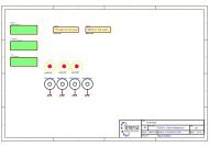
4.1 Patch (Passive) Antenna<br />
When using a passive antenna, please connect the antenna directly to Pin1, Antenna_IN.<br />
Note:<br />
1. Ferrite bead L1 is added for power noise reduction.<br />
2. C1 and C2 bypass capacitor should be put near the module.<br />
For C3, the value chosen depends on the amount of system noise, the range from 1uF to 100uF<br />
is reasonable.<br />
3. Damping resistors R3 and R4 could be modified based on system application for EMI.<br />
4. Resistor R2 is added for Pull-up to VCC.<br />
5. If you need more support and information on antenna implementation, please directly contact<br />
us at sales@gtop-tech.com for further services.<br />
This document is the exclusive property of <strong>GlobalTop</strong> Tech Inc. and should not be distributed, reproduced, into any other format without<br />
prior permission of <strong>GlobalTop</strong> Tech Inc. Specifications subject to change without prior notice.<br />
Copyright © 2011 <strong>GlobalTop</strong> Technology Inc. All Rights Reserved.<br />
25
<strong>GlobalTop</strong> Technology<br />
<strong>Gmm</strong>-<strong>g3</strong> Data Sheet<br />
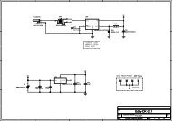
4.2 Active Antenna<br />
When using an active antenna, please connect the antenna directly to Pin1, Antenna_IN.<br />
Note:<br />
Document #<br />
Ver. <strong>V0C</strong><br />
1. Ferrite bead L1 is added for power noise reduction.<br />
2. C1 and C2 bypass capacitor should be put near the module.<br />
3. For C3, the value chosen depends on the amount of system noise, the range from 1uF to 100uF<br />
is reasonable.<br />
4. Damping resistors R3 and R4 could be modified based on system application for EMI.<br />
5. Resistor R2 is added for Pull-up to VCC.<br />
6. If you need more support and information on antenna implementation, please directly contact<br />
us at sales@gtop-tech.com for further services.<br />
This document is the exclusive property of <strong>GlobalTop</strong> Tech Inc. and should not be distributed, reproduced, into any other format without<br />
prior permission of <strong>GlobalTop</strong> Tech Inc. Specifications subject to change without prior notice.<br />
Copyright © 2011 <strong>GlobalTop</strong> Technology Inc. All Rights Reserved.<br />
26
<strong>GlobalTop</strong> Technology<br />
<strong>Gmm</strong>-<strong>g3</strong> Data Sheet<br />
5. Packing and Handling<br />
Document #<br />
Ver. <strong>V0C</strong><br />
GPS modules, like any other SMD devices, are sensitive to moisture, electrostatic discharge, and<br />
temperature. By following the standards outlined in this document for <strong>GlobalTop</strong> GPS module<br />
storage and handling, it is possible to reduce the chances of them being damaged during production<br />
set-up. This document will go through the basics on how <strong>GlobalTop</strong> packages its modules to ensure<br />
they arrive at their destination without any damages and deterioration to performance quality, as<br />
well as some cautionary notes before going through the surface mount process.<br />
Please read the sections II to V carefully to avoid damages permanent damages due to<br />
moisture intake<br />
GPS receiver modules contain highly sensitive electronic circuits and are electronic sensitive<br />
devices and improper handling without ESD protections may lead to permanent damages to<br />
the modules. Please read section VI for more details.<br />
5.1 Moisture Sensitivity<br />
<strong>GlobalTop</strong> GPS modules are moisture sensitive, and must be pre-baked before going through the<br />
solder reflow process. It is important to know that:<br />
<strong>GlobalTop</strong> GPS modules must complete solder reflow process in 72 hours after pre-baking.<br />
This maximum time is otherwise known as “Floor Life”<br />
If the waiting time has exceeded 72 hours, it is possible for the module to suffer damages during the<br />
solder reflow process such as cracks and delamination of the SMD pads due to excess moisture<br />
pressure.<br />
This document is the exclusive property of <strong>GlobalTop</strong> Tech Inc. and should not be distributed, reproduced, into any other format without<br />
prior permission of <strong>GlobalTop</strong> Tech Inc. Specifications subject to change without prior notice.<br />
Copyright © 2011 <strong>GlobalTop</strong> Technology Inc. All Rights Reserved.<br />
27
<strong>GlobalTop</strong> Technology<br />
<strong>Gmm</strong>-<strong>g3</strong> Data Sheet<br />
5.2 Packing<br />
Document #<br />
Ver. <strong>V0C</strong><br />
<strong>GlobalTop</strong> GPS modules are packed in such a way to ensure the product arrives to SMD factory floor<br />
without any damages.<br />
GPS modules are placed individually on to the packaging tray. The trays will then be stacked and<br />
packaged together.<br />
Included are:<br />
1. Two packs of desiccant for moisture absorption<br />
2. One moisture level color coded card for relative humidity percentage.<br />
Each package is then placed inside an antistatic bag (or PE bag) that prevents the modules from<br />
being damaged by electrostatic discharge.<br />
Figure 1: One pack of GPS modules<br />
Each bag is then carefully placed inside two levels of cardboard carton boxes for maximum<br />
protection.<br />
Figure 2: Box protection<br />
This document is the exclusive property of <strong>GlobalTop</strong> Tech Inc. and should not be distributed, reproduced, into any other format without<br />
prior permission of <strong>GlobalTop</strong> Tech Inc. Specifications subject to change without prior notice.<br />
Copyright © 2011 <strong>GlobalTop</strong> Technology Inc. All Rights Reserved.<br />
28
<strong>GlobalTop</strong> Technology<br />
<strong>Gmm</strong>-<strong>g3</strong> Data Sheet<br />
Document #<br />
Ver. <strong>V0C</strong><br />
The moisture color coded card provides an insight to the relative humidity percentage (RH). When<br />
the GPS modules are taken out, it should be around or lower than 30% RH level.<br />
Outside each electrostatic bag is a caution label for moisture sensitive device.<br />
Figure 3: Example of moisture color coded card and caution label<br />
This document is the exclusive property of <strong>GlobalTop</strong> Tech Inc. and should not be distributed, reproduced, into any other format without<br />
prior permission of <strong>GlobalTop</strong> Tech Inc. Specifications subject to change without prior notice.<br />
Copyright © 2011 <strong>GlobalTop</strong> Technology Inc. All Rights Reserved.<br />
29
<strong>GlobalTop</strong> Technology<br />
<strong>Gmm</strong>-<strong>g3</strong> Data Sheet<br />
5.3 Storage and Floor Life Guideline<br />
Document #<br />
Ver. <strong>V0C</strong><br />
Since <strong>GlobalTop</strong> modules must undergo solder-reflow process in 72 hours after it has gone through<br />
pre-baking procedure, therefore if it is not used by then, it is recommended to store the GPS<br />
modules in dry places such as dry cabinet.<br />
The approximate shelf life for <strong>GlobalTop</strong> GPS modules packages is 6 months from the bag seal date,<br />
when store in a non-condensing storage environment (
<strong>GlobalTop</strong> Technology<br />
<strong>Gmm</strong>-<strong>g3</strong> Data Sheet<br />
5.5 ESD Handling<br />
Document #<br />
Ver. <strong>V0C</strong><br />
Please carefully follow the following precautions to prevent severe damage to<br />
GPS modules.<br />
<strong>GlobalTop</strong> GPS modules are sensitive to electrostatic discharges, and thus are Electrostatic Sensitive<br />
Devices (ESD). Careful handling of the GPS modules and in particular to its patch antenna (if included)<br />
and RF_IN pin, must follow the standard ESD safety practices:<br />
Unless there is a galvanic coupling between the local GND and the PCB GND, then the first<br />
point of contact when handling the PCB shall always be between the local GND and PCB GND.<br />
Before working with RF_IN pin, please make sure the GND is connected<br />
When working with RF_IN pin, do not contact any charges capacitors or materials that can<br />
easily develop or store charges such as patch antenna, coax cable, soldering iron.<br />
Please do not touch the mounted patch antenna to prevent electrostatic discharge from the<br />
RF input<br />
When soldering RF_IN pin, please make sure to use an ESD safe soldering iron (tip).<br />
This document is the exclusive property of <strong>GlobalTop</strong> Tech Inc. and should not be distributed, reproduced, into any other format without<br />
prior permission of <strong>GlobalTop</strong> Tech Inc. Specifications subject to change without prior notice.<br />
Copyright © 2011 <strong>GlobalTop</strong> Technology Inc. All Rights Reserved.<br />
31
<strong>GlobalTop</strong> Technology<br />
<strong>Gmm</strong>-<strong>g3</strong> Data Sheet<br />
6. Reflow Soldering Temperature Profile<br />
Document #<br />
Ver. <strong>V0C</strong><br />
The following reflow temperature profile was evaluated by <strong>GlobalTop</strong> and has been proven to be<br />
reliable qualitatively. Please contact us beforehand if you plan to solder this component using a<br />
deviated temperature profile as it may cause significant damage to our module and your device.<br />
All the information in this sheet can only be used only for Pb-free manufacturing process.<br />
6.1 SMT Reflow Soldering Temperature Profile<br />
(Reference Only)<br />
Average ramp-up rate (25 ~ 150°C): 3°C/sec. max.<br />
Average ramp-up rate (270°C to peak): 3°C/sec. max.<br />
Preheat: 175 ± 25°C, 60 ~ 120 seconds<br />
Temperature maintained above 217°C: 60~150 seconds<br />
Peak temperature: 250 +0/-5°C, 20~40 seconds<br />
Ramp-down rate: 6°C/sec. max.<br />
Time 25°C to peak temperature: 8 minutes max.<br />
°C<br />
217°C<br />
25°C<br />
Slop:3°C /sec. max.<br />
Preheat: 175±5°C<br />
Slop:3°C /sec. max.<br />
(217°C to peak)<br />
Peak:250+0/-5°C<br />
20 ~ 40 sec.<br />
60 ~120 sec. 60 ~150 sec.<br />
Slop:6°C /sec. max.<br />
Time (sec)<br />
This document is the exclusive property of <strong>GlobalTop</strong> Tech Inc. and should not be distributed, reproduced, into any other format without<br />
prior permission of <strong>GlobalTop</strong> Tech Inc. Specifications subject to change without prior notice.<br />
Copyright © 2011 <strong>GlobalTop</strong> Technology Inc. All Rights Reserved.<br />
32
<strong>GlobalTop</strong> Technology<br />
<strong>Gmm</strong>-<strong>g3</strong> Data Sheet<br />
Details Suggestions Notes<br />
1 Before proceeding with the reflowsoldering<br />
process, the GPS module must<br />
be pre-baked.<br />
2 Because PCBA (along with the patch<br />
antenna) is highly endothermic during<br />
the reflow-soldering process, extra care<br />
must be paid to the GPS module's solder<br />
joint to see if there are any signs of cold<br />
weld(ing) or false welding.<br />
3 Special attentions are needed for PCBA<br />
board during reflow-soldering to see if<br />
there are any symptoms of bending or<br />
deformation to the PCBA board,<br />
possibility due to the weight of the<br />
module. If so, this will cause concerns at<br />
the latter half of the production process.<br />
4 Before the PCBA is going through the<br />
reflow-soldering process, the production<br />
operators must check by eyesight to see<br />
if there are positional offset to the<br />
module, because it will be difficult to<br />
readjust after the module has gone<br />
through reflow-soldering process.<br />
Pre-bake Time:<br />
6 Hours @ 60°±5°C or<br />
4 Hours @ 70°±5°C<br />
The parameters of the<br />
reflow temperature<br />
must be set accordingly<br />
to module’s reflowsoldering<br />
temperature<br />
profile.<br />
A loading carrier fixture<br />
must be used with PCBA<br />
if the reflow soldering<br />
process is using rail<br />
conveyors for the<br />
production.<br />
The operators must<br />
check by eyesight and<br />
readjust the position<br />
before reflow-soldering<br />
process.<br />
Document #<br />
Ver. <strong>V0C</strong><br />
The maximum tolerated<br />
temperature for the tray is<br />
100°C.<br />
After the pre-baking<br />
process, please make sure<br />
the temperature is<br />
sufficiently cooled down to<br />
35°C or below in order to<br />
prevent any tray<br />
deformation.<br />
Double check to see if the<br />
surrounding components<br />
around the GPS module are<br />
displaying symptoms of<br />
cold weld(ing) or false<br />
welding.<br />
If there is any bending or<br />
deformation to the PCBA<br />
board, this might causes<br />
the PCBA to collide into<br />
one another during the<br />
unloading process.<br />
If the operator is planning<br />
to readjust the module<br />
position, please do not<br />
touch the patch antenna<br />
while the module is hot in<br />
order to prevent rotational<br />
offset between the patch<br />
antenna and module<br />
Note: References to patch antenna is referred to GPS modules with integrated Patch-on-top<br />
antennas (PA/Gms Module Series), and may not be applicable to all GPS modules.<br />
This document is the exclusive property of <strong>GlobalTop</strong> Tech Inc. and should not be distributed, reproduced, into any other format without<br />
prior permission of <strong>GlobalTop</strong> Tech Inc. Specifications subject to change without prior notice.<br />
Copyright © 2011 <strong>GlobalTop</strong> Technology Inc. All Rights Reserved.<br />
33
<strong>GlobalTop</strong> Technology<br />
<strong>Gmm</strong>-<strong>g3</strong> Data Sheet<br />
Details Suggestions Notes<br />
5 Before handling the PCBA, they must be<br />
cooled to 35°C or below after they have<br />
gone through the reflow-soldering<br />
process, in order to prevent positional<br />
shift that might occur when the module is<br />
still hot.<br />
6 1. When separating the PCBA panel into<br />
individual pieces using the V-Cut process,<br />
special attentions are needed to ensure<br />
there are sufficient gap between patch<br />
antennas so the patch antennas are not<br />
in contact with one another.<br />
2. If V-Cut process is not available and the<br />
pieces must be separated manually,<br />
please make sure the operators are not<br />
using excess force which may cause<br />
rotational offset to the patch antennas.<br />
7 When separating panel into individual<br />
pieces during latter half of the production<br />
process, special attentions are needed to<br />
ensure the patch antennas do not come<br />
in contact with one another in order to<br />
prevent chipped corners or positional<br />
shifts.<br />
1. Can use electric fans<br />
behind the Reflow<br />
machine to cool them<br />
down.<br />
2. Cooling the PCBA can<br />
prevent the module<br />
from shifting due to<br />
fluid effect.<br />
1. The blade and the<br />
patch antenna must<br />
have a distance gap<br />
greater than 0.6mm.<br />
2. Do not use patch<br />
antenna as the leverage<br />
point when separating<br />
the panels by hand.<br />
Use tray to separate<br />
individual pieces.<br />
Document #<br />
Ver. <strong>V0C</strong><br />
It is very easy to cause<br />
positional offset to the<br />
module and its patch<br />
antenna when handling the<br />
PCBA under high<br />
temperature.<br />
1. Test must be performed<br />
first to determine if V-Cut<br />
process is going to be used.<br />
There must be enough space<br />
to ensure the blade and<br />
patch antenna do not touch<br />
one another.<br />
2. An uneven amount of<br />
manual force applied to the<br />
separation will likely to<br />
cause positional shift in<br />
patch antenna and module.<br />
It is possible to chip corner<br />
and/or cause a shift in<br />
position if patch antennas<br />
come in contact with each<br />
other.<br />
Note: References to patch antenna is referred to GPS modules with integrated Patch-on-top<br />
antennas (PA/Gms Module Series), and may not be applicable to all GPS modules.<br />
This document is the exclusive property of <strong>GlobalTop</strong> Tech Inc. and should not be distributed, reproduced, into any other format without<br />
prior permission of <strong>GlobalTop</strong> Tech Inc. Specifications subject to change without prior notice.<br />
Copyright © 2011 <strong>GlobalTop</strong> Technology Inc. All Rights Reserved.<br />
34
<strong>GlobalTop</strong> Technology<br />
<strong>Gmm</strong>-<strong>g3</strong> Data Sheet<br />
Other Cautionary Notes on Reflow-Soldering Process:<br />
1. Module must be pre-baked before going through SMT solder reflow process.<br />
Document #<br />
Ver. <strong>V0C</strong><br />
2. The usage of solder paste should follow “first in first out” principle. Opened solder paste<br />
needs to be monitored and recorded in a timely fashion (can refer to IPQC for related<br />
documentation and examples).<br />
3. Temperature and humidity must be controlled in SMT production line and storage area.<br />
Temperature of 23°C, 60±5% RH humidity is recommended. (please refer to IPQC for related<br />
documentation and examples)<br />
4. When performing solder paste printing, please notice if the amount of solder paste is in<br />
excess or insufficient, as both conditions may lead to defects such as electrical shortage,<br />
empty solder and etc.<br />
5. Make sure the vacuum mouthpiece is able to bear the weight of the GPS module to prevent<br />
positional shift during the loading process.<br />
6. Before the PCBA is going through the reflow-soldering process, the operators should check<br />
by eyesight to see if there are positional offset to the module.<br />
7. The reflow temperature and its profile data must be measured before the SMT process and<br />
match the levels and guidelines set by IPQC.<br />
8. If SMT protection line is running a double-sided process for PCBA, please process GPS<br />
module during the second pass only to avoid repeated reflow exposures of the GPS module.<br />
Please contact <strong>GlobalTop</strong> beforehand if you must process GPS module during the 1 st pass of<br />
double-side process.<br />
Figure 6.2: Place GPS module right-side up when running reflow-solder process, do not invert.<br />
This document is the exclusive property of <strong>GlobalTop</strong> Tech Inc. and should not be distributed, reproduced, into any other format without<br />
prior permission of <strong>GlobalTop</strong> Tech Inc. Specifications subject to change without prior notice.<br />
Copyright © 2011 <strong>GlobalTop</strong> Technology Inc. All Rights Reserved.<br />
35
<strong>GlobalTop</strong> Technology<br />
<strong>Gmm</strong>-<strong>g3</strong> Data Sheet<br />
9. Module must be pre-baked before going through SMT solder reflow process.<br />
Document #<br />
Ver. <strong>V0C</strong><br />
10. The usage of solder paste should follow “first in first out” principle. Opened solder paste<br />
needs to be monitored and recorded in a timely fashion (can refer to IPQC for related<br />
documentation and examples).<br />
11. Temperature and humidity must be controlled in SMT production line and storage area.<br />
Temperature of 23°C, 60±5% RH humidity is recommended. (please refer to IPQC for related<br />
documentation and examples)<br />
12. When performing solder paste printing, please notice if the amount of solder paste is in<br />
excess or insufficient, as both conditions may lead to defects such as electrical shortage,<br />
empty solder and etc.<br />
13. The reflow temperature and its profile data must be measured before the SMT process and<br />
match the levels and guidelines set by IPQC.<br />
6.2 Manual Soldering<br />
Soldering iron:<br />
Bit Temperature: Under 380°C Time: Under 3 sec.<br />
Notes:<br />
1. Please do not directly touch the soldering pads on the surface of the PCB board, in order to<br />
prevent further oxidation<br />
2. The solder paste must be defrosted to room temperature before use so it can return to its<br />
optimal working temperature. The time required for this procedure is unique and dependent<br />
on the properties of the solder paste used.<br />
3. The steel plate must be properly assessed before and after use, so its measurement stays<br />
strictly within the specification set by SOP.<br />
4. Please watch out for the spacing between soldering joint, as excess solder may cause<br />
electrical shortage<br />
5. Please exercise with caution and do not use extensive amount of flux due to possible siphon<br />
effects on neighboring components, which may lead to electrical shortage.<br />
6. Please do not use the heat gun for long periods of time when removing the shielding or<br />
inner components of the GPS module, as it is very likely to cause a shift to the inner<br />
components and will leads to electrical shortage.<br />
This document is the exclusive property of <strong>GlobalTop</strong> Tech Inc. and should not be distributed, reproduced, into any other format without<br />
prior permission of <strong>GlobalTop</strong> Tech Inc. Specifications subject to change without prior notice.<br />
Copyright © 2011 <strong>GlobalTop</strong> Technology Inc. All Rights Reserved.<br />
36
<strong>GlobalTop</strong> Technology<br />
<strong>Gmm</strong>-<strong>g3</strong> Data Sheet<br />
7. Contact Information<br />
<strong>GlobalTop</strong> Technology Inc.<br />
Address: No.16 Nan-ke 9rd Road Science-based Industrial Park, Tainan 741, Taiwan<br />
Tel: +886-6-5051268<br />
Fax: +886-6-5053381<br />
Website: www.gtop-tech.com<br />
Email: sales@gtop-tech.com<br />
Document #<br />
Ver. <strong>V0C</strong><br />
This document is the exclusive property of <strong>GlobalTop</strong> Tech Inc. and should not be distributed, reproduced, into any other format without<br />
prior permission of <strong>GlobalTop</strong> Tech Inc. Specifications subject to change without prior notice.<br />
Copyright © 2011 <strong>GlobalTop</strong> Technology Inc. All Rights Reserved.<br />
37