GaAs IC Reliability in Plastic Packages PDF - TriQuint Semiconductor
GaAs IC Reliability in Plastic Packages PDF - TriQuint Semiconductor
GaAs IC Reliability in Plastic Packages PDF - TriQuint Semiconductor

Create successful ePaper yourself
Turn your PDF publications into a flip-book with our unique Google optimized e-Paper software.
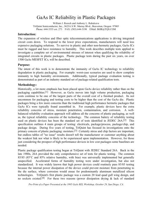
<strong>GaAs</strong> <strong>IC</strong> <strong>Reliability</strong> <strong>in</strong> <strong>Plastic</strong> <strong>Packages</strong><br />
William J. Roesch and Anthony L. Rubalcava<br />
TriQu<strong>in</strong>t <strong>Semiconductor</strong>, Inc., 3625A S.W. Murray Blvd., Beaverton, Oregon 97005<br />
Phone: 644-3535 ext. 273 FAX: (503) 644-3198 EMail: BillR@TQS.COM<br />
Introduction:<br />
The expansion of wireless and fiber optic telecommunications applications is driv<strong>in</strong>g <strong>in</strong>tegrated<br />
circuit costs down. To respond to the lower price expectations, manufacturers will need less<br />
expensive packag<strong>in</strong>g solutions. To survive <strong>in</strong> plastic and other non-hermetic packages, <strong>GaAs</strong> <strong>IC</strong>s<br />
must be rugged and have resistance to humidity. This work describes multiple tests applied to<br />
<strong>in</strong>vestigate a complete set of environmental stresses of <strong>in</strong>terest when qualify<strong>in</strong>g the reliability of<br />
<strong>in</strong>tegrated circuits <strong>in</strong> plastic packages. <strong>Plastic</strong> package tests dur<strong>in</strong>g the past six years, on over<br />
1500 <strong>GaAs</strong> MESFET <strong>IC</strong>s, will be described.<br />
Purpose:<br />
The <strong>in</strong>tent of this work is to demonstrate the immunity of <strong>GaAs</strong> <strong>IC</strong> technology to reliability<br />
degradation <strong>in</strong> plastic packag<strong>in</strong>g. For example: worst-case scenarios are used to show complete<br />
immunity to high humidity environments. Additionally, typical package evaluation test<strong>in</strong>g is<br />
demonstrated as part of an <strong>in</strong>dustry standard set of package-related qualification tests.<br />
Methodology:<br />
Historically, a lot more emphasis has been placed upon <strong>GaAs</strong> device reliability rather than on the<br />
packag<strong>in</strong>g capabilities. [1] However, as <strong>GaAs</strong> moves <strong>in</strong>to high volume production, packag<strong>in</strong>g<br />
costs cont<strong>in</strong>ue to be one of the largest parts of the overall cost of a f<strong>in</strong>ished product. Its not<br />
uncommon for packag<strong>in</strong>g and test<strong>in</strong>g costs to be higher than the cost of the <strong>GaAs</strong> die. <strong>Plastic</strong><br />
packages br<strong>in</strong>g a few more concerns than the traditional high performance hermetic packages that<br />
<strong>GaAs</strong> <strong>IC</strong>s were typically found assembled <strong>in</strong>. For example, plastic devices have the extra<br />
reliability concerns of stress, moisture penetration, contam<strong>in</strong>ation, and corrosion. A wellbalanced<br />
reliability evaluation approach will address all the concerns of plastic packag<strong>in</strong>g, as well<br />
as, the typical reliability concerns of the technology. The common battery of reliability test<strong>in</strong>g<br />
used on plastic devices has been the standard set of tests identified <strong>in</strong> JEDEC 26A. [2] This<br />
specification outl<strong>in</strong>es 4 ma<strong>in</strong> groups of test<strong>in</strong>g: electricals, package/process, package/chip, and<br />
package design. Dur<strong>in</strong>g five years of test<strong>in</strong>g, TriQu<strong>in</strong>t has focused its <strong>in</strong>vestigations onto the<br />
primary concern of plastic packag<strong>in</strong>g: moisture. [3] Certa<strong>in</strong>ly stress and chip factors are important,<br />
but endless tables of "no issue" results doesn't tell the manufacturer or customer anyth<strong>in</strong>g about<br />
the weakest l<strong>in</strong>k nor what is likely to be experienced upon implementation. However, for those<br />
just consider<strong>in</strong>g the prospect of high performance devices <strong>in</strong> low cost packages some basel<strong>in</strong>es are<br />
needed.<br />
<strong>Plastic</strong> package qualification test<strong>in</strong>g began at TriQu<strong>in</strong>t with JEDEC Standard 26A. Back <strong>in</strong> the<br />
late 1980s, 26A provided the only comprehensive set of tests for plastic test<strong>in</strong>g. The common<br />
85/85 (85°C and 85% relative humidity, with bias) was universally implemented but generally<br />
unspecified. Accelerated forms of humidity test<strong>in</strong>g were under <strong>in</strong>vestigation, but also not<br />
standardized. It was widely known that high power devices could rout<strong>in</strong>ely pass 85/85 test<strong>in</strong>g<br />
because the <strong>in</strong>ternal power dissipation of the device could prevent moisture from penetrat<strong>in</strong>g to<br />
the die surface, where corrosion would ensue for predom<strong>in</strong>antly alum<strong>in</strong>um metallized silicon<br />
technologies. TriQu<strong>in</strong>t's first plastic package was a custom 20 lead quad gull w<strong>in</strong>g design, and<br />
no sockets existed. [4] For these two reasons (power dissipation dry<strong>in</strong>g & lack of standard<br />
Pre-Pr<strong>in</strong>t of a Paper Presented at the 1995 <strong>GaAs</strong> REL Workshop, October 29, San Diego, CA.
<strong>GaAs</strong> <strong>IC</strong> <strong>Reliability</strong> <strong>in</strong> <strong>Plastic</strong> <strong>Packages</strong><br />
sockets) moisture test<strong>in</strong>g and lifetest<strong>in</strong>g was conducted <strong>in</strong> an unbiased mode. Otherwise, JEDEC<br />
26A was followed to the letter. [2]<br />
After success with the standard plastic qualification test<strong>in</strong>g, attempts to f<strong>in</strong>d more str<strong>in</strong>gent<br />
criteria were made. TriQu<strong>in</strong>t conducted the next set of tests us<strong>in</strong>g 85/85 (with m<strong>in</strong>imal bias) and<br />
HAST (highly accelerated stress test<strong>in</strong>g) <strong>in</strong> a side-by-side manner. [5] Although some failures<br />
could be generated on eng<strong>in</strong>eer<strong>in</strong>g samples, the production devices were capable of pass<strong>in</strong>g this<br />
test also. Complimentary thermal excursion tests were also performed to evaluate mechanical<br />
stress issues.<br />
Standard test flows were subsequently developed for device qualification, and three have been<br />
completed at the time of publication. [6],[7],[8] Special eng<strong>in</strong>eer<strong>in</strong>g tests have also been conducted<br />
to look specifically at the moisture resistance of <strong>GaAs</strong> devices.<br />
There are two special considerations for <strong>GaAs</strong> devices <strong>in</strong> plastic packages. First, the die coat<strong>in</strong>g<br />
material which is often used, and the second is high temperature lifetest<strong>in</strong>g. Die coat material is<br />
common for many circuits when encapsulated. It is used for <strong>GaAs</strong> devices for two primary<br />
reasons: coat<strong>in</strong>g ma<strong>in</strong>ta<strong>in</strong>s a more stable dielectric environment for the die surface and the coat<strong>in</strong>g<br />
also provides mechanical protection for airbridges dur<strong>in</strong>g mold<strong>in</strong>g and dur<strong>in</strong>g thermo-mechanical<br />
stresses. While the die coat is not necessarily needed to encapsulate <strong>GaAs</strong> die, it does tend to<br />
<strong>in</strong>crease the yield of packaged devices, and reduce the chance of a random reliability failure<br />
caused by mechanical damage. [5]<br />
High temperature lifetest<strong>in</strong>g is a concern s<strong>in</strong>ce <strong>GaAs</strong> devices are normally subjected to very highly<br />
accelerated lifetests. S<strong>in</strong>ce primary <strong>GaAs</strong> failure mechanisms can be easily accelerated by<br />
temperature, lifetests are sometimes conducted at temperatures up to 300°C. High temperature<br />
test<strong>in</strong>g is not normally conducted <strong>in</strong> plastic packages because the glass transition temperature of<br />
the plastic is usually between 160°C and 180°C. At temperatures significantly above the glass<br />
transition temperature, the plastic actually beg<strong>in</strong>s to "melt." Cont<strong>in</strong>ued cycles above the glass<br />
transition temperature can cause anomalous failures which would never be observed dur<strong>in</strong>g actual<br />
use. TriQu<strong>in</strong>t characterizes the effect of the glass transition temperature threshold by conduct<strong>in</strong>g<br />
temperature ramp tests and lifetests at multiple temperatures.<br />
Figure 1. Effect of <strong>Plastic</strong> on Lifetest Results<br />
Page 2
<strong>GaAs</strong> <strong>IC</strong> <strong>Reliability</strong> <strong>in</strong> <strong>Plastic</strong> <strong>Packages</strong><br />
Figure 1 shows the effect of a threshold triggered failure mechanism caused by the glass transition<br />
temperature of plastic mold<strong>in</strong>g compound. Once the threshold is crossed, the anomalous<br />
mechanism can significantly reduce the measured lifetimes, thus <strong>in</strong>dicat<strong>in</strong>g an artificially high<br />
activation energy and an unrealistic lifetime expectation. The anomalous results are revealed by<br />
additional results which are more typical at 200°C (not yet completed - no failures at 3,000<br />
hours), 225°C, and even at 250°C. These results <strong>in</strong>dicate the need for step stress or ramp stress<br />
tests to identify the threshold levels. [9] Note that plastic results are similar to all other <strong>IC</strong> results.<br />
Results:<br />
The central set of test<strong>in</strong>g performed <strong>in</strong> this study <strong>in</strong>volved the completion of all package-related<br />
tests outl<strong>in</strong>ed <strong>in</strong> JEDEC-STD-26A: General Specifications for <strong>Plastic</strong> Encapsulated<br />
Microcircuits for Use <strong>in</strong> Rugged Applications. The tests performed <strong>in</strong>clude: physical dimensions,<br />
mark<strong>in</strong>g permanency, solderability, autoclave, lifetest, humidity test, lead <strong>in</strong>tegrity, resistance to<br />
solder<strong>in</strong>g heat, thermal shock, and temperature cycl<strong>in</strong>g. Both biased and unbiased humidity and<br />
lifetest<strong>in</strong>g were performed. To counteract the thermal effect of test<strong>in</strong>g without bias, the lifetest<br />
was operated at 150°C ambient, which is 25°C hotter than 125°C ambient stated <strong>in</strong> the<br />
specification. Both the plastic package and the die were therefore exposed to greater<br />
temperatures <strong>in</strong> this unbiased version of the lifetest. This hotter condition is more str<strong>in</strong>gent than<br />
biased test<strong>in</strong>g at lower temperatures s<strong>in</strong>ce <strong>GaAs</strong> failure mechanisms are primarily accelerated by<br />
temperature. In an unbiased humidity test, the moisture is allowed to saturate the plastic and<br />
penetrate completely to the die surface. Whereas <strong>in</strong> a biased test, the heat that is generated on the<br />
circuit tends to drive the moisture away. Both life and humidity tests exceeded the m<strong>in</strong>imum<br />
specified 1,000 hours with no failures. All standard test<strong>in</strong>g was completed without experienc<strong>in</strong>g a<br />
failure. [2]<br />
Table 1. Typical <strong>Plastic</strong> Package Qualification Requirements<br />
Requirements def<strong>in</strong>ed by JEDEC Standard No. 26-A<br />
Specification for <strong>Plastic</strong> Encapsulated Microcircuits for Use <strong>in</strong> Rugged Applications.<br />
JEDEC-STD-22 (rejects allowed)<br />
Group Test Description Method Condition Samples<br />
1. Physical Dimensions B100 Per Data Sheet Package Draw<strong>in</strong>g 2 (0)<br />
2. Mark Permanency B107 Resistance To Solvents 4 (0)<br />
B 3. Solderability B102 25 Leads M<strong>in</strong>imum<br />
Accept Number = 1<br />
3<br />
A102 Unbiased 2 Atmospheres<br />
4. Autoclave<br />
Saturated Steam, +121°C<br />
96 Hours M<strong>in</strong>imum<br />
Ambient = 125°C or<br />
100 (1)<br />
1. Biased Lifetest A108 Tpeak
<strong>GaAs</strong> <strong>IC</strong> <strong>Reliability</strong> <strong>in</strong> <strong>Plastic</strong> <strong>Packages</strong><br />
Additional tests have been performed to validate good reliability performance <strong>in</strong> plastic.<br />
Accelerated temperatures between 135°C and 260°C have been employed, <strong>in</strong> plastic. Biased<br />
HAST tests at 85% RH and 135°C have also been performed. [5] By successfully complet<strong>in</strong>g this<br />
series of tests, six separate device/package types have been qualified start<strong>in</strong>g as early as 1990.<br />
Table 2. Device Qualification Requirements<br />
Test<br />
Sample<br />
Item Name Purpose Condition/Method Size<br />
1 Thermal Temperature Profile IR Thermal Imag<strong>in</strong>g 1<br />
Analysis Peak Temperature<br />
Liquid Crystal<br />
2 ESD Damage Threshold MIL-STD-883, m<strong>in</strong>.9<br />
Sensitivity<br />
Method 3015<br />
3 Voltage F<strong>in</strong>d Design Limit & Verify Voltage Step Stress <strong>in</strong> 0.5 Volt 3 to 5<br />
Ramp Absolute Maximum Rat<strong>in</strong>g Increments at Room Temperature<br />
4 Temperature F<strong>in</strong>d Design Limit & Verify Ramp Ambient Temperature to 3<br />
Ramp Absolute Maximum Rat<strong>in</strong>g Fixture Failure at Nom<strong>in</strong>al Bias.<br />
5 Lifetest Determ<strong>in</strong>e Median Nom<strong>in</strong>al Static Bias 30 to<br />
Lifetime<br />
Accelerated Temperature. 100<br />
6 Temperature Material Stress and 1000 Cycles, -40°C to +125°C 77<br />
Cycle Thermal Mismatch.<br />
7 Resistance to Test Immunity to Unbiased Test at 300°C 9<br />
Solder<strong>in</strong>g Heat Assembly Procedures<br />
for 5 m<strong>in</strong>utes<br />
Table 3. <strong>Plastic</strong> Device Qualification Summary<br />
Part Type Package Device Sample<br />
Item<br />
Qualification Qualification Size<br />
1 Multifunction AS<strong>IC</strong>, 20 p<strong>in</strong> quad gull w<strong>in</strong>g Yes 58<br />
2 SPST Switch, 20 p<strong>in</strong> quad gull w<strong>in</strong>g Yes Yes 486<br />
3 Amplifier/Switch AS<strong>IC</strong>, 24 p<strong>in</strong> SSOP Yes Yes 437<br />
4 800 MHz Amplifier, 8 p<strong>in</strong> SO<strong>IC</strong> Yes 203<br />
5 RF<strong>IC</strong> Downconverter, 14 p<strong>in</strong> SO<strong>IC</strong> Yes 185<br />
6 Transmit/Receive Amp, 24 p<strong>in</strong> SSOP Yes 134<br />
Specific reliability experiments have also been performed to focus on the most critical factor for<br />
silicon <strong>IC</strong>s <strong>in</strong> plastic, humidity. Two special experiments <strong>in</strong>volv<strong>in</strong>g humidity acceleration were<br />
performed <strong>in</strong> cavity packages to represent "worst case" scenarios. Comb<strong>in</strong>ations of extra water<br />
and extra epoxy (which can outgas water vapor under some conditions) were purposely<br />
<strong>in</strong>troduced <strong>in</strong>to package cavities prior to seal. The devices were first cooled to -20°C for about<br />
30 m<strong>in</strong>utes <strong>in</strong> an unbiased mode. This step was designed to condense all the moisture on the<br />
cavity and die surfaces <strong>in</strong>side the package. Then the devices were powered and forced to 80°C<br />
for a 15 m<strong>in</strong>ute dwell. The power was removed from the devices and they were frozen aga<strong>in</strong>.<br />
Twenty-one 132-p<strong>in</strong> devices were run <strong>in</strong> this test for 1000 cycles without any failures develop<strong>in</strong>g.<br />
The samples were measured at <strong>in</strong>terim po<strong>in</strong>ts of 100, 200, and 500 cycles us<strong>in</strong>g a product test<strong>in</strong>g<br />
sequence which conducts 129 functional and parametric evaluations. Even under conditions<br />
exceed<strong>in</strong>g 200,000 ppm moisture, no anomalous defects or changes were observed. [10],[11]<br />
Page 4
<strong>GaAs</strong> <strong>IC</strong> <strong>Reliability</strong> <strong>in</strong> <strong>Plastic</strong> <strong>Packages</strong><br />
An additional worst case test was designed to specifically evaluate the <strong>GaAs</strong> technology <strong>in</strong> humid<br />
environments with m<strong>in</strong>imal <strong>in</strong>teractions of any particular package style. A special Technology<br />
Characterization Vehicle (TCV) was selected to provide the maximum number of <strong>in</strong>dependent<br />
active devices, so that various bias conditions could be <strong>in</strong>vestigated <strong>in</strong> humidity. The TCV was<br />
packaged <strong>in</strong> an <strong>in</strong>dustry standard Dual In-l<strong>in</strong>e Package (DIP) without any lid. The packages were<br />
biased while <strong>in</strong> a test chamber provid<strong>in</strong>g an 85°C environment with 85% relative humidity. To<br />
reiterate, the die were completely exposed to the high humidity and temperature while biased for<br />
the duration of the test. The samples were measured at <strong>in</strong>terim po<strong>in</strong>ts of 168 and 500 hours<br />
us<strong>in</strong>g an automated electrical measurement system which conducts 5 key parametric tests. In all,<br />
294 FETs were tested for 1,000 hours. The devices survived, and exhibited less than 1% change<br />
<strong>in</strong> DC parameters. [3] This type of accelerated eng<strong>in</strong>eer<strong>in</strong>g test<strong>in</strong>g on unprotected dice would not<br />
be used on a silicon device because of the expected corrosion on the bond pads and alum<strong>in</strong>um<br />
<strong>in</strong>terconnect layers.<br />
A relatively new test for plastic devices is the "popcorn" test. The popcorn effect is caused when<br />
moisture <strong>in</strong>side a plastic package turns to steam and expands rapidly dur<strong>in</strong>g vapor phase or<br />
<strong>in</strong>frared solder reflow. Under certa<strong>in</strong> conditions, the force from the expand<strong>in</strong>g moisture can cause<br />
stresses <strong>in</strong>side the package. In the most severe cases, the stress can result <strong>in</strong> external package<br />
cracks. This is commonly referred to as the popcorn phenomenon because the <strong>in</strong>ternal stress<br />
causes the package to bulge and then crack with an audible "pop." Surface mount devices are<br />
more susceptible to this problem because of the solder<strong>in</strong>g methods used and because they have<br />
smaller m<strong>in</strong>imum plastic thickness. A group of 20 lead quad gull w<strong>in</strong>g devices were subjected to<br />
72 hours <strong>in</strong> a pressure cooker at 121°C, 100% humidity, and one atmosphere of overpressure.<br />
The group conta<strong>in</strong>ed samples molded <strong>in</strong> different molds and with different leadframe f<strong>in</strong>ishes. The<br />
devices were then run through an IR furnace that heats to a maximum setpo<strong>in</strong>t of 330°C. The<br />
devices were then <strong>in</strong>spected under high magnification, and no cracks were observed. [12] Results<br />
are summarized <strong>in</strong> Table 4.<br />
Sample<br />
Size<br />
Mold<br />
Type<br />
Table 4. Popcorn Test Details<br />
20 Lead <strong>Plastic</strong> Quad Gull W<strong>in</strong>g Package<br />
Lead<br />
Condition<br />
Hours <strong>in</strong><br />
Pressure Cooker<br />
Page 5<br />
IR Solder<strong>in</strong>g<br />
Cycles<br />
Failures<br />
10 Old Nickel Plated 72 2 0<br />
10 Old Bare Copper 72 2 0<br />
10 New Nickel Plated 72 2 0<br />
6 New Bare Copper 72 2 0<br />
Total Parts = 36 72 2 0<br />
Impact<br />
The results of this work clearly demonstrate acceptable reliability performance of <strong>GaAs</strong> <strong>IC</strong><br />
technology <strong>in</strong> plastic packag<strong>in</strong>g. This not only provides evidence that <strong>GaAs</strong> devices are ready for<br />
low-cost non-hermetic packages, but that <strong>GaAs</strong> <strong>IC</strong>s may have superior reliability performance<br />
compared to silicon devices, particularly under accelerated humidity conditions.
<strong>GaAs</strong> <strong>IC</strong> <strong>Reliability</strong> <strong>in</strong> <strong>Plastic</strong> <strong>Packages</strong><br />
Table 5. <strong>Plastic</strong> Package / Humidity Test Summary<br />
Test Description <strong>Plastic</strong> or Eng<strong>in</strong>eer<strong>in</strong>g Sample Size<br />
Standard Tests <strong>Plastic</strong> 1503<br />
Special Humidity Tests Eng<strong>in</strong>eer<strong>in</strong>g Mode 351<br />
Totals 1854<br />
Summary<br />
In conclusion, <strong>GaAs</strong> die have been found to be reliable <strong>in</strong> plastic package test<strong>in</strong>g. The follow<strong>in</strong>g<br />
po<strong>in</strong>ts have also been discussed:<br />
1) It is important to conduct various tests that stress the expected failure mechanisms for<br />
plastic packages <strong>in</strong> addition to stress<strong>in</strong>g the die itself.<br />
2) Historical test<strong>in</strong>g over the past five years has <strong>in</strong>dicated that the reliability of <strong>GaAs</strong><br />
devices <strong>in</strong> plastic packag<strong>in</strong>g has similar reliability to cavity packaged devices.<br />
3) It is important to characterize the threshold triggered failure mechanisms that affect<br />
plastic packages because of low glass transition temperatures.<br />
4) Highly accelerated moisture tests eng<strong>in</strong>eered for exam<strong>in</strong><strong>in</strong>g expected plastic failure<br />
mechanisms have <strong>in</strong>dicated that <strong>GaAs</strong> devices have a better immunity to corrosion<br />
exhibited by alum<strong>in</strong>um <strong>in</strong>terconnects used <strong>in</strong> typical silicon technologies.<br />
References:<br />
1. Predict<strong>in</strong>g <strong>GaAs</strong> <strong>Reliability</strong> With Accelerated Test<strong>in</strong>g. Invited Paper, Presented at the MANTECH<br />
Conference, Reno Nevada, Bill Roesch and Richard Allen, April 1990, 1 page Abstract.<br />
2. 20 Lead <strong>Plastic</strong> Package <strong>Reliability</strong> Qualification Report. REL. REPORT. 92-02, Tony Rubalcava,<br />
Dec. 1992, 6 pages.<br />
3. Humidity Resistance of <strong>GaAs</strong> <strong>IC</strong>s. Presented at the 1994 <strong>GaAs</strong> <strong>IC</strong> Symposium, Philadelphia, Penn.<br />
Bill Roesch, Ross W<strong>in</strong>ters, Tony Rubalcava, & Bharati Ingle, October 1994, 4 pages.<br />
4. <strong>Reliability</strong> Of <strong>Plastic</strong> Packag<strong>in</strong>g For <strong>GaAs</strong> <strong>IC</strong>s. Presented at the MANTECH Conference, Reno<br />
Nevada, Bill Roesch, Tony Rubalcava, and Bharati Ingle, April 1990, 4 pages<br />
5. SSOP24 <strong>Plastic</strong> Package <strong>Reliability</strong> Qualification Report. RELIABILITY REPORT 94-03,<br />
Tony Rubalcava, October 1994, 8 pages.<br />
6. TQ9132 <strong>Reliability</strong> Device Qualification Report. RELIABILITY REPORT 95-01, Tony Rubalcava,<br />
1995, 6 pages.<br />
7. TQ9203 <strong>Reliability</strong> Device Qualification Report. RELIABILITY REPORT 95-02, Tony Rubalcava,<br />
1995, 7 pages.<br />
8. TQ9205 <strong>Reliability</strong> Device Qualification Report. RELIABILITY REPORT 95-03, Tony Rubalcava,<br />
1995, 7 pages.<br />
9. F<strong>in</strong>d<strong>in</strong>g Low Activation Energy Failure Mechanisms. Presented at the Advanced Microelectronics<br />
Technology Qualification, <strong>Reliability</strong>, and Logistics Workshop, Seattle WA., Bill Roesch,<br />
Aug. 1991, 4 pages.<br />
10. Moisture Resistance of <strong>GaAs</strong> <strong>IC</strong>s: Break<strong>in</strong>g the 5,000 PPM Barrier. Presented at the 1993 GOMAC,<br />
New Orleans, Louisiana, Bill Roesch & Bharati Ingle, November 1993, 3 pages.<br />
11. Moisture Condensation Test Report. RELIABILITY REPORT 93-01, Bill Roesch, January 1993,<br />
6 pages.<br />
12. Popcorn Tests Completed. Quarterly <strong>Reliability</strong> Report, Third Quarter 1992, Bill Roesch, 4 pages.<br />
Page 6