High-Performance BiHEMT HBT / E-D pHEMT Integration - TriQuint ...
High-Performance BiHEMT HBT / E-D pHEMT Integration - TriQuint ...
High-Performance BiHEMT HBT / E-D pHEMT Integration - TriQuint ...

You also want an ePaper? Increase the reach of your titles
YUMPU automatically turns print PDFs into web optimized ePapers that Google loves.
structure is physically widest. Additionally, a large part of<br />
<strong>HBT</strong> self-heating is dissipated through a thermal shunt on<br />
top of the active emitter.<br />
DEVICE FABRICATION<br />
The <strong>BiHEMT</strong> process represents a modification of<br />
<strong>TriQuint</strong>’s <strong>HBT</strong> process, with <strong>pHEMT</strong> specific steps<br />
inserted between the <strong>HBT</strong> device-specific process steps<br />
and the passive/interconnects metallization formation.<br />
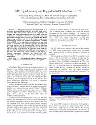
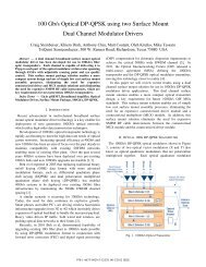
Fig. 1 shows a cross-sectional schematic of <strong>TriQuint</strong>’s<br />
<strong>HBT</strong> and E/D <strong>pHEMT</strong> technology. Device fabrication is<br />
relatively straightforward, with four types of process steps:<br />
<strong>HBT</strong>-specific metallization, such as at emitter and base;<br />
etches that uncover the different <strong>HBT</strong> and <strong>pHEMT</strong> epi<br />
layers; <strong>pHEMT</strong>-gate processing; and the fabrication of<br />
common structures, such as capacitors, resistors, and metal<br />
interconnects. In order to reduce process complexity,<br />
several device-specific process steps, such as <strong>HBT</strong><br />
collector and <strong>pHEMT</strong> source/drain ohmic metallization are<br />
combined. No degradation is seen in either <strong>pHEMT</strong> or<br />
<strong>HBT</strong> device characteristics as a result of this consolidation.<br />
Fabrication starts with standard <strong>HBT</strong> processing modules,<br />
including emitter metallization, emitter mesa formation,<br />
and base metallization.<br />
Then, the base mesa is formed by etching all the way<br />
down to an etch stop at the top of the subcollector. Once<br />
the subcollector is reached, an additional etch step is added<br />
that etches away the subcollector in the field, in order to<br />
uncover the <strong>pHEMT</strong> epitaxial structure. <strong>pHEMT</strong><br />
processing then begins with wide recess pattern<br />
lithography and etch, and a shallow implant is performed<br />
into the remaining <strong>pHEMT</strong> epi in the field in order to<br />
electrically isolate all devices.<br />
After the implant, a common <strong>HBT</strong>/<strong>pHEMT</strong> ohmic<br />
metallization is done, with the collector metallization<br />
sitting on top of the subcollector for the <strong>HBT</strong> and lower<br />
down in the epi, on top of the cap layer, for the <strong>pHEMT</strong>s.<br />
Following ohmic contact formation comes the proprietary<br />
D-mode and E-mode narrow recess formations and gate<br />
depositions; for both types of device, etch stops facilitate<br />
the recess and 0.7 um gates are formed. Here we note that<br />
our usual E/D process employs a 0.5 um gate. A 0.5 um<br />
gate <strong>BiHEMT</strong> process is currently under development, but<br />
narrow gate lithography is considerably complicated by the<br />
highly nonplanar <strong>BiHEMT</strong> structure.<br />
After <strong>HBT</strong> and <strong>pHEMT</strong> device formation, 50<br />
ohm/square NiCr resistors are formed, as well as MIM<br />
capacitors with 1200 pF/mm 2 capacitance. The bottom of<br />
the MIM layer is used as a local interconnect, and<br />
subsequent plated gold layers of 2 um and 4 um thickness<br />
are used for global interconnects. Finally, the entire<br />
Dielectric<br />
D-Mode<br />
<strong>pHEMT</strong><br />
Figure 1. Cross section of <strong>TriQuint</strong>’s <strong>BiHEMT</strong> process,<br />
showing GaAs/InGaP <strong>HBT</strong>, D-mode AlGaAs/InGaAs<br />
<strong>pHEMT</strong>, E-mode AlGaAs/InGaAs <strong>pHEMT</strong>, resistors,<br />
capacitors, and three levels of interconnect metal.<br />
structure is covered by a thick layer of nitride for<br />
passivation, and wafer thinning and through via formation<br />
follow.<br />
<strong>BiHEMT</strong> DEVICE CHARACTERIZATION<br />
As previously mentioned, <strong>HBT</strong>-specific epitaxy and<br />
process in the <strong>BiHEMT</strong> process are for the most part<br />
unchanged from the standard <strong>HBT</strong> process. As a result,<br />
most <strong>HBT</strong> device parameters – both DC and RF – are<br />
substantially the same as they are in the original <strong>TriQuint</strong><br />
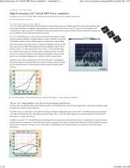
<strong>HBT</strong> power amplifier process. Fig. 2(a) and (b) shows<br />
representative Gummel plot and common-emitter I-V<br />
characteristics for a 3x(3x45) um 2 emitter <strong>HBT</strong>. Typical<br />
beta is 80 and BVcbo = 24 V, with Ft = 30 GHz and Fmax =<br />
55 GHz.<br />
There are only two significant differences in <strong>HBT</strong><br />
characteristics between the <strong>BiHEMT</strong> <strong>HBT</strong> and our<br />
dedicated <strong>HBT</strong> process. First, the <strong>BiHEMT</strong> <strong>HBT</strong> has a<br />
slightly higher collector resistance. This is because in the<br />
Ic (A)<br />
0.10<br />
0.08<br />
0.06<br />
0.04<br />
0.02<br />
0.00<br />
E-Mode<br />
<strong>pHEMT</strong><br />
Metal2 – 4 um<br />
Metal1 – 2 um<br />
Dielectric<br />
InGaP/GaAs<br />
<strong>HBT</strong><br />
Semi-Insulating GaAs Substrate<br />
0.0 1.0 2.0 3.0 4.0<br />
V ce (V)<br />
Fig. 2(a). Common-emitter I-V for a 3x(3x45) um 2 emitter<br />
<strong>HBT</strong> in the <strong>BiHEMT</strong> process.<br />
NiCr<br />
MIM<br />
Isolation Implant<br />
Metal0