ESD Sensitivity of TriQuint 100-mm Processes and Circuit ...
ESD Sensitivity of TriQuint 100-mm Processes and Circuit ...
ESD Sensitivity of TriQuint 100-mm Processes and Circuit ...

You also want an ePaper? Increase the reach of your titles
YUMPU automatically turns print PDFs into web optimized ePapers that Google loves.
Kathy Wood 3/23/2007<br />
Application Note<br />
<strong>ESD</strong> <strong>Sensitivity</strong> <strong>of</strong> <strong>TriQuint</strong> Texas <strong>Processes</strong> <strong>and</strong> <strong>Circuit</strong> Components<br />
GaAs semiconductor devices have a high sensitivity to Electrostatic Discharge (<strong>ESD</strong>) <strong>and</strong> care<br />
must be taken to prevent damage. This document provides typical Human Body Model (HBM)<br />
failure thresholds for individual circuit components. Based on the data below <strong>and</strong> careful<br />
examination <strong>of</strong> a circuit, its overall <strong>ESD</strong> sensitivity can be assessed by finding the least robust<br />
component <strong>of</strong> the circuit.<br />
The most <strong>ESD</strong> sensitive components in a typical GaAs MMIC are:<br />
a) small Field Effect Transistor (FET) devices,<br />
b) small Schottky diodes,<br />
c) small MIM (Metal-Insulator-Metal) capacitors,<br />
d) narrow gaps <strong>of</strong> isolated substrate between metal lines at a different potential.<br />
1 Field Effect Transistors<br />
In the typical co<strong>mm</strong>on source configuration, FET devices are most vulnerable to negative<br />
discharges to the gate. FET devices can h<strong>and</strong>le somewhat greater positive discharges to the<br />
gate, <strong>and</strong> positive or negative discharges to the drain. In all cases, <strong>ESD</strong> sensitivity is strongly<br />
dependent on gate width.<br />
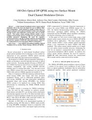
1.1 General Characteristics<br />
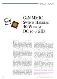
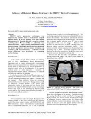
<strong>ESD</strong> sensitivities are described in the figure below for the typical co<strong>mm</strong>on-source FET<br />
configuration.<br />
• Positive discharges to the gate<br />
can be conducted through the<br />
Schottky gate junction if the<br />
gate width is sufficiently large.<br />
+<br />
-<br />
G<br />
• Greatest vulnerability is for<br />
negative discharges into<br />
the gate.<br />
1<br />
S<br />
• Positive or negative discharges<br />
to the drain can be conducted<br />
through the FET channel if the<br />
gate width is sufficiently large.<br />
D<br />
+/-<br />
• For any terminal <strong>and</strong> polarity,<br />
<strong>ESD</strong> sensitivity scales with<br />
gate width. Smaller devices<br />
are more vulnerable.
Kathy Wood 3/23/2007<br />
1.2 Typical Failure Thresholds: Discharge to the Gate<br />
The <strong>ESD</strong> test procedure is to perform HBM discharges at a given voltage <strong>and</strong> then check for<br />
damage. The test voltage is raised in 50V increments. Typical failure thresholds for positive <strong>and</strong><br />
negative discharges to the gate are listed below for 300 µm FETs.<br />
Process type Failure<br />
threshold,<br />
Positive G-S<br />
Application Note<br />
discharge, V<br />
Failure<br />
threshold,<br />
Positive G-D<br />
discharge, V<br />
2<br />
Failure<br />
threshold,<br />
Negative G-S<br />
discharge, V<br />
Failure<br />
threshold,<br />
Negative G-D<br />
discharge, V<br />
0.5 µm HFET 2MI 1200 1150 -230 -300<br />
0.35 µm PWR pHEMT 3MI 1020 970 -200 -200<br />
0.25 µm <strong>mm</strong>W pHEMT 3MI 950 1030 -150 -170<br />
0.15 µm PWR pHEMT 3MI 780 750 -130 -150<br />
0.15 µm LN mHEMT 3MI 700 1<strong>100</strong> * *<br />
* Failed after first 50 V step<br />
All processes are much more sensitive to negative discharges on the gate. The mHEMT process<br />
is particularly sensitive to negative discharges; mHEMT devices failed after the initial -50 V<br />
step. On the other h<strong>and</strong>, mHEMT devices can h<strong>and</strong>le positive discharges to the gate at levels<br />
similar to other technologies.<br />
Also note that wrist straps, co<strong>mm</strong>only used to minimize <strong>ESD</strong> when h<strong>and</strong>ling sensitive devices,<br />
are typically specified to limit <strong>ESD</strong> levels to 200 V or less. Clearly, 200 V is not adequate for<br />
300 µm pHEMT <strong>and</strong> mHEMT devices.<br />
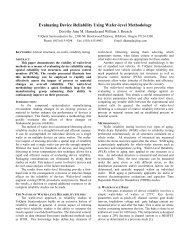
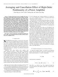
1.3 Scaling <strong>of</strong> <strong>ESD</strong> <strong>Sensitivity</strong> with FET Gate Width<br />
<strong>ESD</strong> sensitivity decreases as gate width is increased. HBM failure voltages are directly<br />
proportional to FET size. Very small devices, < 200 µm, are extremely sensitive. Data shown<br />
below is for positive <strong>and</strong> negative discharges, Gate-Source <strong>and</strong> Drain-Source. The HBM<br />
discharge is applied across two terminals, with the other terminal floating. Gate leakage is<br />
monitored to determine failure. Negative discharges to the gate typically result in an abrupt<br />
catastrophic failure. On the other h<strong>and</strong>, positive <strong>and</strong> negative Drain-Source <strong>and</strong> positive Gate-<br />
Source <strong>and</strong> Gate-Drain discharges can cause gradual increases in gate leakage without causing<br />
catastrophic failure. The data below are for voltage levels that resulted in less than 1 kΩ <strong>of</strong> gate<br />
resistance.
Kathy Wood 3/23/2007<br />
Average V fail (V)<br />
Average V fail (V)<br />
0<br />
-200<br />
-400<br />
-600<br />
-800<br />
-<strong>100</strong>0<br />
0 200 400 600 800 <strong>100</strong>0 1200 1400 1600<br />
4000<br />
3500<br />
3000<br />
2500<br />
2000<br />
1500<br />
<strong>100</strong>0<br />
500<br />
Application Note<br />
HBM failure voltages, - gate-source zaps<br />
FET size (µm)<br />
HBM failure voltages, + gate-source zaps<br />
0<br />
0 200 400 600 800 <strong>100</strong>0 1200 1400 1600<br />
FET size (µm)<br />
3<br />
0.25 µm <strong>mm</strong>W pHEMT 3MI<br />
Linear Fit to 0.25 µm <strong>mm</strong>W pHEMT 3MI<br />
(excluding 300 µm FETs)<br />
0.5 µm HFET 2MI<br />
Linear Fit to 0.5 µm HFET 2MI<br />
0.25 µm <strong>mm</strong>W pHEMT 3MI<br />
Linear Fit to 0.25 µm <strong>mm</strong>W pHEMT 3MI<br />
(excluding 1440 µm FETs)<br />
0.5 µm HFET 2MI<br />
Linear Fit to 0.5 µm HFET 2MI
Kathy Wood 3/23/2007<br />
Average V fail (V)<br />
3500<br />
3000<br />
2500<br />
2000<br />
1500<br />
<strong>100</strong>0<br />
500<br />
0<br />
0 250 500 750 <strong>100</strong>0 1250 1500 1750 2000 2250 2500<br />
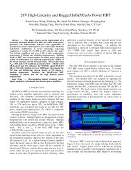
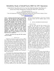
2 Diodes<br />
0.25 pHEMT HBM failure voltages, + drain-source zaps<br />
Application Note<br />
FET size (µm)<br />
4<br />
0.25 µm <strong>mm</strong>W pHEMT 3MI, + D-S zaps<br />
Linear Fit excluding 300 µm FETs<br />
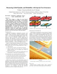
<strong>ESD</strong> sensitivity <strong>of</strong> diodes is similar to that <strong>of</strong> FETs. Typical data for 4 µm diodes fabricated in<br />
the 0.25 µm pHEMT process are shown below. Very small diodes are vulnerable to positive <strong>and</strong><br />
negative discharges to the anode. Larger periphery diodes can be used as protection devices for<br />
positive discharges to the anode.
Kathy Wood 3/23/2007<br />
Average Failure Voltage<br />
Application Note<br />
<strong>100</strong>0<br />
750<br />
500<br />
250<br />
0<br />
-250<br />
-500<br />
-750<br />
-<strong>100</strong>0<br />
3 TaN Resistors<br />
0 50 <strong>100</strong> 150 200 250 300<br />
Anode Periphery, um<br />
5<br />
Anode-Cathode Positive<br />
Anode-Cathode Negative<br />
Based on TLP (Transmission Line Pulse) data, TaN resistors can h<strong>and</strong>le for short time intervals<br />
(<strong>100</strong> ns) typical <strong>of</strong> HBM <strong>ESD</strong> transients significantly higher current densities than the DC<br />
current limits. TaN resistors remain fairly constant in value during high current transients with a<br />
very slight resistance drop just prior to failure. The transient failure current density <strong>of</strong> TaN<br />
resistors depends on the physical size <strong>of</strong> the resistor, with large resistors failing at lower current<br />
densities than small resistors.<br />
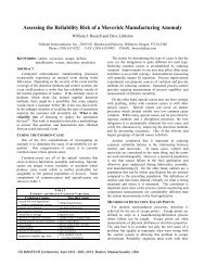
4 Capacitors<br />
<strong>ESD</strong> sensitivity <strong>of</strong> capacitors depends on dielectric thickness <strong>and</strong> is a linear function <strong>of</strong> capacitor<br />
size for a given capacitor type. The 3MI process includes three capacitor types: Type G (1200<br />
pF/<strong>mm</strong> 2 ), Type 7 (300 pF/<strong>mm</strong> 2 ), <strong>and</strong> Type 9 (240 pF/<strong>mm</strong> 2 ). The 2MI process includes one type<br />
<strong>of</strong> capacitor similar to the type 7 3MI capacitor. Note that for small sizes, Type G is the most<br />
sensitive, while for large sizes, it is the most robust type <strong>of</strong> capacitor. During the <strong>ESD</strong> event, a<br />
large area Type G capacitor has enough conductivity in the dielectric to dissipate the <strong>ESD</strong> charge,<br />
providing a measure <strong>of</strong> self-protection. The figure below illustrates the behavior <strong>of</strong> type G, 7,<br />
<strong>and</strong> 9 capacitors as a function <strong>of</strong> increasing capacitance (area), as well as the fact that using 2<br />
capacitors in series results in doubling the HBM failure voltage compared to a single capacitor<br />
with the same total capacitance.
Kathy Wood 3/23/2007<br />
HBM Failure Voltage (V)<br />
HBM Failure Voltage (V)<br />
3500<br />
3000<br />
2500<br />
2000<br />
1500<br />
<strong>100</strong>0<br />
500<br />
0<br />
-500<br />
-<strong>100</strong>0<br />
-1500<br />
-2000<br />
-2500<br />
-3000<br />
0 1 2 3 4 5 6 7 8 9 10 11 12<br />
5 Isolated Substrate Gaps<br />
Isolated substrate gaps between metal lines at a different potential are as sensitive to <strong>ESD</strong> as any<br />
other circuit component. Spacing between metallization on the circuit needs to be optimized for<br />
achieving the desired <strong>ESD</strong> robustness level. Our test results suggest that a safe scaling rule is<br />
30 V HBM voltage per micron <strong>of</strong> spacing.<br />
6 References<br />
1. J. M. Beall <strong>and</strong> G. I. Dr<strong>and</strong>ova, <strong>ESD</strong> Protection for pHEMT MMIC Amplifiers, 2005<br />
Compound Semiconductor Integrated <strong>Circuit</strong> Symposium Technical Digest, p. 276, 2005.<br />
2. G. I. Dr<strong>and</strong>ova, J. M. Beall, <strong>and</strong> K. D. Decker, SiN Capacitors <strong>and</strong> <strong>ESD</strong>, 2006 MANTECH<br />
Technical Digest, p. 83, 2006.<br />
Application Note<br />
Type 9<br />
Type 7<br />
Type G<br />
Two type G in series<br />
Type 9<br />
Type 7<br />
Type G<br />
Two type G in series<br />
Capacitance (pF)<br />
6